EP2635241B1 - Vorrichtung zur positionierung einer gefässprothese bzw. eines gefässprothesensystems - Google Patents
Vorrichtung zur positionierung einer gefässprothese bzw. eines gefässprothesensystems Download PDFInfo
- Publication number
- EP2635241B1 EP2635241B1 EP11781956.5A EP11781956A EP2635241B1 EP 2635241 B1 EP2635241 B1 EP 2635241B1 EP 11781956 A EP11781956 A EP 11781956A EP 2635241 B1 EP2635241 B1 EP 2635241B1
- Authority
- EP
- European Patent Office
- Prior art keywords
- graft
- prosthesis
- fenestration
- branch
- sheath
- Prior art date
- Legal status (The legal status is an assumption and is not a legal conclusion. Google has not performed a legal analysis and makes no representation as to the accuracy of the status listed.)
- Active
Links
- 239000000463 material Substances 0.000 description 59
- 210000005166 vasculature Anatomy 0.000 description 33
- 238000000034 method Methods 0.000 description 30
- 210000004204 blood vessel Anatomy 0.000 description 16
- 210000003484 anatomy Anatomy 0.000 description 12
- 210000000709 aorta Anatomy 0.000 description 11
- 210000001367 artery Anatomy 0.000 description 11
- 230000000452 restraining effect Effects 0.000 description 7
- 229920002614 Polyether block amide Polymers 0.000 description 6
- 239000008280 blood Substances 0.000 description 6
- 210000004369 blood Anatomy 0.000 description 6
- 210000002254 renal artery Anatomy 0.000 description 5
- 238000013461 design Methods 0.000 description 4
- 235000020637 scallop Nutrition 0.000 description 4
- 239000010935 stainless steel Substances 0.000 description 4
- 229910001220 stainless steel Inorganic materials 0.000 description 4
- 206010002329 Aneurysm Diseases 0.000 description 3
- 241000237503 Pectinidae Species 0.000 description 3
- 210000000702 aorta abdominal Anatomy 0.000 description 3
- 239000003550 marker Substances 0.000 description 3
- 210000001363 mesenteric artery superior Anatomy 0.000 description 3
- 239000007769 metal material Substances 0.000 description 3
- 229920001343 polytetrafluoroethylene Polymers 0.000 description 3
- 239000004810 polytetrafluoroethylene Substances 0.000 description 3
- FAPWRFPIFSIZLT-UHFFFAOYSA-M Sodium chloride Chemical compound [Na+].[Cl-] FAPWRFPIFSIZLT-UHFFFAOYSA-M 0.000 description 2
- 210000002376 aorta thoracic Anatomy 0.000 description 2
- 208000007474 aortic aneurysm Diseases 0.000 description 2
- 230000017531 blood circulation Effects 0.000 description 2
- 210000001715 carotid artery Anatomy 0.000 description 2
- 210000002434 celiac artery Anatomy 0.000 description 2
- 230000007423 decrease Effects 0.000 description 2
- 230000010339 dilation Effects 0.000 description 2
- 229920000295 expanded polytetrafluoroethylene Polymers 0.000 description 2
- 238000002594 fluoroscopy Methods 0.000 description 2
- 210000003090 iliac artery Anatomy 0.000 description 2
- 238000003780 insertion Methods 0.000 description 2
- 230000037431 insertion Effects 0.000 description 2
- 230000003447 ipsilateral effect Effects 0.000 description 2
- 238000012986 modification Methods 0.000 description 2
- 230000004048 modification Effects 0.000 description 2
- HLXZNVUGXRDIFK-UHFFFAOYSA-N nickel titanium Chemical compound [Ti].[Ti].[Ti].[Ti].[Ti].[Ti].[Ti].[Ti].[Ti].[Ti].[Ti].[Ni].[Ni].[Ni].[Ni].[Ni].[Ni].[Ni].[Ni].[Ni].[Ni].[Ni].[Ni].[Ni].[Ni] HLXZNVUGXRDIFK-UHFFFAOYSA-N 0.000 description 2
- 229910001000 nickel titanium Inorganic materials 0.000 description 2
- 210000000056 organ Anatomy 0.000 description 2
- BASFCYQUMIYNBI-UHFFFAOYSA-N platinum Chemical compound [Pt] BASFCYQUMIYNBI-UHFFFAOYSA-N 0.000 description 2
- 239000011780 sodium chloride Substances 0.000 description 2
- 210000003270 subclavian artery Anatomy 0.000 description 2
- 239000000126 substance Substances 0.000 description 2
- 230000002792 vascular Effects 0.000 description 2
- 208000002251 Dissecting Aneurysm Diseases 0.000 description 1
- 241001465754 Metazoa Species 0.000 description 1
- 241000237509 Patinopecten sp. Species 0.000 description 1
- 201000008982 Thoracic Aortic Aneurysm Diseases 0.000 description 1
- 210000001015 abdomen Anatomy 0.000 description 1
- 208000002223 abdominal aortic aneurysm Diseases 0.000 description 1
- 230000003187 abdominal effect Effects 0.000 description 1
- 230000002159 abnormal effect Effects 0.000 description 1
- 238000004026 adhesive bonding Methods 0.000 description 1
- 229910045601 alloy Inorganic materials 0.000 description 1
- 239000000956 alloy Substances 0.000 description 1
- 238000004873 anchoring Methods 0.000 description 1
- 230000001174 ascending effect Effects 0.000 description 1
- 239000000560 biocompatible material Substances 0.000 description 1
- 210000004556 brain Anatomy 0.000 description 1
- 238000004891 communication Methods 0.000 description 1
- 230000007547 defect Effects 0.000 description 1
- 230000001627 detrimental effect Effects 0.000 description 1
- 239000012530 fluid Substances 0.000 description 1
- PCHJSUWPFVWCPO-UHFFFAOYSA-N gold Chemical compound [Au] PCHJSUWPFVWCPO-UHFFFAOYSA-N 0.000 description 1
- 229910052737 gold Inorganic materials 0.000 description 1
- 239000010931 gold Substances 0.000 description 1
- 239000007943 implant Substances 0.000 description 1
- 210000003734 kidney Anatomy 0.000 description 1
- 230000003902 lesion Effects 0.000 description 1
- 239000002184 metal Substances 0.000 description 1
- 229910052751 metal Inorganic materials 0.000 description 1
- 210000000496 pancreas Anatomy 0.000 description 1
- 230000010412 perfusion Effects 0.000 description 1
- 230000002093 peripheral effect Effects 0.000 description 1
- 229910052697 platinum Inorganic materials 0.000 description 1
- 230000003014 reinforcing effect Effects 0.000 description 1
- 230000001850 reproductive effect Effects 0.000 description 1
- 238000011144 upstream manufacturing Methods 0.000 description 1
- 230000037303 wrinkles Effects 0.000 description 1
Images


Classifications
-
- A—HUMAN NECESSITIES
- A61—MEDICAL OR VETERINARY SCIENCE; HYGIENE
- A61F—FILTERS IMPLANTABLE INTO BLOOD VESSELS; PROSTHESES; DEVICES PROVIDING PATENCY TO, OR PREVENTING COLLAPSING OF, TUBULAR STRUCTURES OF THE BODY, e.g. STENTS; ORTHOPAEDIC, NURSING OR CONTRACEPTIVE DEVICES; FOMENTATION; TREATMENT OR PROTECTION OF EYES OR EARS; BANDAGES, DRESSINGS OR ABSORBENT PADS; FIRST-AID KITS
- A61F2/00—Filters implantable into blood vessels; Prostheses, i.e. artificial substitutes or replacements for parts of the body; Appliances for connecting them with the body; Devices providing patency to, or preventing collapsing of, tubular structures of the body, e.g. stents
- A61F2/95—Instruments specially adapted for placement or removal of stents or stent-grafts
- A61F2/954—Instruments specially adapted for placement or removal of stents or stent-grafts for placing stents or stent-grafts in a bifurcation
-
- A—HUMAN NECESSITIES
- A61—MEDICAL OR VETERINARY SCIENCE; HYGIENE
- A61F—FILTERS IMPLANTABLE INTO BLOOD VESSELS; PROSTHESES; DEVICES PROVIDING PATENCY TO, OR PREVENTING COLLAPSING OF, TUBULAR STRUCTURES OF THE BODY, e.g. STENTS; ORTHOPAEDIC, NURSING OR CONTRACEPTIVE DEVICES; FOMENTATION; TREATMENT OR PROTECTION OF EYES OR EARS; BANDAGES, DRESSINGS OR ABSORBENT PADS; FIRST-AID KITS
- A61F2/00—Filters implantable into blood vessels; Prostheses, i.e. artificial substitutes or replacements for parts of the body; Appliances for connecting them with the body; Devices providing patency to, or preventing collapsing of, tubular structures of the body, e.g. stents
- A61F2/02—Prostheses implantable into the body
- A61F2/04—Hollow or tubular parts of organs, e.g. bladders, tracheae, bronchi or bile ducts
- A61F2/06—Blood vessels
- A61F2/07—Stent-grafts
-
- A—HUMAN NECESSITIES
- A61—MEDICAL OR VETERINARY SCIENCE; HYGIENE
- A61F—FILTERS IMPLANTABLE INTO BLOOD VESSELS; PROSTHESES; DEVICES PROVIDING PATENCY TO, OR PREVENTING COLLAPSING OF, TUBULAR STRUCTURES OF THE BODY, e.g. STENTS; ORTHOPAEDIC, NURSING OR CONTRACEPTIVE DEVICES; FOMENTATION; TREATMENT OR PROTECTION OF EYES OR EARS; BANDAGES, DRESSINGS OR ABSORBENT PADS; FIRST-AID KITS
- A61F2/00—Filters implantable into blood vessels; Prostheses, i.e. artificial substitutes or replacements for parts of the body; Appliances for connecting them with the body; Devices providing patency to, or preventing collapsing of, tubular structures of the body, e.g. stents
- A61F2/95—Instruments specially adapted for placement or removal of stents or stent-grafts
- A61F2/962—Instruments specially adapted for placement or removal of stents or stent-grafts having an outer sleeve
- A61F2/97—Instruments specially adapted for placement or removal of stents or stent-grafts having an outer sleeve the outer sleeve being splittable
-
- A—HUMAN NECESSITIES
- A61—MEDICAL OR VETERINARY SCIENCE; HYGIENE
- A61F—FILTERS IMPLANTABLE INTO BLOOD VESSELS; PROSTHESES; DEVICES PROVIDING PATENCY TO, OR PREVENTING COLLAPSING OF, TUBULAR STRUCTURES OF THE BODY, e.g. STENTS; ORTHOPAEDIC, NURSING OR CONTRACEPTIVE DEVICES; FOMENTATION; TREATMENT OR PROTECTION OF EYES OR EARS; BANDAGES, DRESSINGS OR ABSORBENT PADS; FIRST-AID KITS
- A61F2/00—Filters implantable into blood vessels; Prostheses, i.e. artificial substitutes or replacements for parts of the body; Appliances for connecting them with the body; Devices providing patency to, or preventing collapsing of, tubular structures of the body, e.g. stents
- A61F2/82—Devices providing patency to, or preventing collapsing of, tubular structures of the body, e.g. stents
- A61F2/86—Stents in a form characterised by the wire-like elements; Stents in the form characterised by a net-like or mesh-like structure
- A61F2/89—Stents in a form characterised by the wire-like elements; Stents in the form characterised by a net-like or mesh-like structure the wire-like elements comprising two or more adjacent rings flexibly connected by separate members
-
- A—HUMAN NECESSITIES
- A61—MEDICAL OR VETERINARY SCIENCE; HYGIENE
- A61F—FILTERS IMPLANTABLE INTO BLOOD VESSELS; PROSTHESES; DEVICES PROVIDING PATENCY TO, OR PREVENTING COLLAPSING OF, TUBULAR STRUCTURES OF THE BODY, e.g. STENTS; ORTHOPAEDIC, NURSING OR CONTRACEPTIVE DEVICES; FOMENTATION; TREATMENT OR PROTECTION OF EYES OR EARS; BANDAGES, DRESSINGS OR ABSORBENT PADS; FIRST-AID KITS
- A61F2/00—Filters implantable into blood vessels; Prostheses, i.e. artificial substitutes or replacements for parts of the body; Appliances for connecting them with the body; Devices providing patency to, or preventing collapsing of, tubular structures of the body, e.g. stents
- A61F2/02—Prostheses implantable into the body
- A61F2/04—Hollow or tubular parts of organs, e.g. bladders, tracheae, bronchi or bile ducts
- A61F2/06—Blood vessels
- A61F2002/061—Blood vessels provided with means for allowing access to secondary lumens
-
- A—HUMAN NECESSITIES
- A61—MEDICAL OR VETERINARY SCIENCE; HYGIENE
- A61F—FILTERS IMPLANTABLE INTO BLOOD VESSELS; PROSTHESES; DEVICES PROVIDING PATENCY TO, OR PREVENTING COLLAPSING OF, TUBULAR STRUCTURES OF THE BODY, e.g. STENTS; ORTHOPAEDIC, NURSING OR CONTRACEPTIVE DEVICES; FOMENTATION; TREATMENT OR PROTECTION OF EYES OR EARS; BANDAGES, DRESSINGS OR ABSORBENT PADS; FIRST-AID KITS
- A61F2/00—Filters implantable into blood vessels; Prostheses, i.e. artificial substitutes or replacements for parts of the body; Appliances for connecting them with the body; Devices providing patency to, or preventing collapsing of, tubular structures of the body, e.g. stents
- A61F2/02—Prostheses implantable into the body
- A61F2/04—Hollow or tubular parts of organs, e.g. bladders, tracheae, bronchi or bile ducts
- A61F2/06—Blood vessels
- A61F2002/065—Y-shaped blood vessels
-
- A—HUMAN NECESSITIES
- A61—MEDICAL OR VETERINARY SCIENCE; HYGIENE
- A61F—FILTERS IMPLANTABLE INTO BLOOD VESSELS; PROSTHESES; DEVICES PROVIDING PATENCY TO, OR PREVENTING COLLAPSING OF, TUBULAR STRUCTURES OF THE BODY, e.g. STENTS; ORTHOPAEDIC, NURSING OR CONTRACEPTIVE DEVICES; FOMENTATION; TREATMENT OR PROTECTION OF EYES OR EARS; BANDAGES, DRESSINGS OR ABSORBENT PADS; FIRST-AID KITS
- A61F2/00—Filters implantable into blood vessels; Prostheses, i.e. artificial substitutes or replacements for parts of the body; Appliances for connecting them with the body; Devices providing patency to, or preventing collapsing of, tubular structures of the body, e.g. stents
- A61F2/02—Prostheses implantable into the body
- A61F2/04—Hollow or tubular parts of organs, e.g. bladders, tracheae, bronchi or bile ducts
- A61F2/06—Blood vessels
- A61F2/07—Stent-grafts
- A61F2002/075—Stent-grafts the stent being loosely attached to the graft material, e.g. by stitching
-
- A—HUMAN NECESSITIES
- A61—MEDICAL OR VETERINARY SCIENCE; HYGIENE
- A61F—FILTERS IMPLANTABLE INTO BLOOD VESSELS; PROSTHESES; DEVICES PROVIDING PATENCY TO, OR PREVENTING COLLAPSING OF, TUBULAR STRUCTURES OF THE BODY, e.g. STENTS; ORTHOPAEDIC, NURSING OR CONTRACEPTIVE DEVICES; FOMENTATION; TREATMENT OR PROTECTION OF EYES OR EARS; BANDAGES, DRESSINGS OR ABSORBENT PADS; FIRST-AID KITS
- A61F2/00—Filters implantable into blood vessels; Prostheses, i.e. artificial substitutes or replacements for parts of the body; Appliances for connecting them with the body; Devices providing patency to, or preventing collapsing of, tubular structures of the body, e.g. stents
- A61F2/82—Devices providing patency to, or preventing collapsing of, tubular structures of the body, e.g. stents
- A61F2002/821—Ostial stents
-
- A—HUMAN NECESSITIES
- A61—MEDICAL OR VETERINARY SCIENCE; HYGIENE
- A61F—FILTERS IMPLANTABLE INTO BLOOD VESSELS; PROSTHESES; DEVICES PROVIDING PATENCY TO, OR PREVENTING COLLAPSING OF, TUBULAR STRUCTURES OF THE BODY, e.g. STENTS; ORTHOPAEDIC, NURSING OR CONTRACEPTIVE DEVICES; FOMENTATION; TREATMENT OR PROTECTION OF EYES OR EARS; BANDAGES, DRESSINGS OR ABSORBENT PADS; FIRST-AID KITS
- A61F2220/00—Fixations or connections for prostheses classified in groups A61F2/00 - A61F2/26 or A61F2/82 or A61F9/00 or A61F11/00 or subgroups thereof
- A61F2220/0025—Connections or couplings between prosthetic parts, e.g. between modular parts; Connecting elements
- A61F2220/0075—Connections or couplings between prosthetic parts, e.g. between modular parts; Connecting elements sutured, ligatured or stitched, retained or tied with a rope, string, thread, wire or cable
-
- A—HUMAN NECESSITIES
- A61—MEDICAL OR VETERINARY SCIENCE; HYGIENE
- A61F—FILTERS IMPLANTABLE INTO BLOOD VESSELS; PROSTHESES; DEVICES PROVIDING PATENCY TO, OR PREVENTING COLLAPSING OF, TUBULAR STRUCTURES OF THE BODY, e.g. STENTS; ORTHOPAEDIC, NURSING OR CONTRACEPTIVE DEVICES; FOMENTATION; TREATMENT OR PROTECTION OF EYES OR EARS; BANDAGES, DRESSINGS OR ABSORBENT PADS; FIRST-AID KITS
- A61F2250/00—Special features of prostheses classified in groups A61F2/00 - A61F2/26 or A61F2/82 or A61F9/00 or A61F11/00 or subgroups thereof
- A61F2250/0004—Special features of prostheses classified in groups A61F2/00 - A61F2/26 or A61F2/82 or A61F9/00 or A61F11/00 or subgroups thereof adjustable
- A61F2250/0008—Special features of prostheses classified in groups A61F2/00 - A61F2/26 or A61F2/82 or A61F9/00 or A61F11/00 or subgroups thereof adjustable for adjusting a position by translation along an axis or two perpendicular axes
Definitions
- Endoluminal vascular prostheses delivery devices for use in the treatment of aneurysms at branches of arterial vessels, in particular the aorta, are described.
- An abdominal aortic aneurysm is a sac caused by an abnormal dilation of the wall of the aorta, a major artery of the body, as it passes through the abdomen.
- the diseased region of the blood vessels can extend across branch vessels.
- the blood flow into these branch vessels is critical for the perfusion of the peripheral regions of the body and vital organs.
- Many arteries branch off the aorta For example, the carotid arteries supply blood into the brain, the renal arteries supply blood into the kidneys, the superior mesenteric artery ("SMA") supplies the pancreas, the hypogastric arteries supply blood to the reproductive organs, and the subclavian arteries supply blood to the arms.
- SMA superior mesenteric artery
- the hypogastric arteries supply blood to the reproductive organs
- the subclavian arteries supply blood to the arms.
- the branch vessels may also be affected.
- Thoracic aortic aneurysms may involve the subclavian and carotid arteries, abdominal aneurysms may involve the SMA, renal and hypogastric arteries.
- Aortic dissections may involve all branch vessels mentioned above. When this occurs, it may be detrimental to implant a conventional tubular graft or stent graft in this location of the aorta or the blood vessel, since such a graft may obstruct the flow of blood from the aorta into the branches.
- Prior branch graft arrangements are complex and require many steps of insertion and removal to orient and align fenestrations in a main body to the surrounding anatomy and still more steps to insert, deploy, and seal a branch graft (covered stent) to the main stent graft body and to the wall of the branch vessel without unacceptable leakage.
- the main graft is positioned within the main blood vessel such as the aorta so that the lateral openings (also referred to herein as fenestrations) can be aligned with the branch blood vessels, to allow blood to flow through the openings in the main graft and into the branch vessels.
- the positions of the branch blood vessels can vary from one patient's anatomy to the next, the graft systems disclosed herein allow a surgeon to adjust the position of the fenestrations in the main body so as to align them with the branch vessels to improve the efficiency of branch graft deployment.
- the branch graft system can comprise a tubular expandable main body and at least one fenestration or at least one branch graft at any desired location.
- the main graft body and/or the branch graft can be made from an expandable material, such as but not limited to ePTFE.
- the main graft can have two fenestrations or branch grafts formed therein at generally diametrically opposed locations or at positions that are offset from the diametrically opposed positions.
- cutouts, scallops, or fenestrations such as but not limited to a fenestration for the superior mesenteric artery ("SMA"), can be formed in the main graft depending on the patient's anatomy and position of the graft.
- SMA superior mesenteric artery
- the main graft body can have a tubular shape and can have a diameter that can be significantly larger than the diameter of the target vessel into which the graft is intended to be deployed.
- the oversized diameter of a portion of the main graft can provide excess or slack graft material in the main graft to allow the fenestrations to each be moved in one or a combination of lateral, axial and angular directions so that the fenestrations can be aligned with the branch arteries.
- One or more branch grafts can be supported by the main graft body adjacent to the one or more fenestrations (openings) that can be formed in the main graft body.
- a compressed branch graft is small enough to allow it to be manipulated into the desired vascular position by moving the branch graft over a guidewire.
- the branch graft can be expanded to the diameter of the branch vessel by mechanical means, which can be a dilation balloon, or by the removal of a surrounding restraint in the case of a self-expanding device.
- Embodiments relate to a fenestrated graft deployment system, comprising a delivery catheter having a catheter body, a prosthesis having a main graft body, the main graft body having lumen therethrough and a first opening laterally through a wall of the main graft body, a first guidewire prepositioned within the delivery catheter extending through at least a portion of the catheter body into a main lumen of the endoluminal prosthesis and through the first opening in the wall of the prosthesis when the delivery catheter is in a predeployment state.
- Embodiments of the system have a first fenestration alignment device extending through at least a portion of the delivery catheter configured to be axially moveable relative to the first guidewire.
- the first fenestration alignment device can be configured such that a portion of the fenestration alignment device contacts the main graft body adjacent to the first opening to approximately align the first fenestration with an ostium of a target branch vessel when advanced relative to the fenestration.
- a fenestration push device for use in a fenestrated prostheses deployment catheter, comprising a body portion defining a lumen therethrough, the lumen having a first diameter or cross-sectional size or perimeter, and a protrusion supported at or adjacent to a distal end of the body portion, the protrusion projecting away from an outside surface of the body portion and defining a second cross-sectional or perimeter size.
- the second cross-sectional size of the fenestration push device at the location of the protrusion is greater than the first diameter or size of the body portion.
- the second cross-sectional size of the protrusion is greater than a cross-sectional size of a fenestration formed in a respective fenestrated graft.
- a method of deploying a fenestrated endoluminal prosthesis in a patient's vasculature comprising advancing a catheter supporting the endoluminal prosthesis therein through a patient's vasculature to a target vessel location, wherein the prosthesis has a main graft body comprising a first opening through a wall thereof, advancing a first guide sheath through the first opening and into a first branch vessel, and advancing a first fenestration alignment device into contact with the prosthesis adjacent to the first opening through the wall of the prosthesis so as to approximately align the first opening with an ostium of the first branch vessel.
- an endoluminal prosthesis comprising advancing a catheter supporting the endoluminal prosthesis therein through a patient's vasculature to a target vessel location, advancing one or more catheters through one or more fenestrations formed in the main graft body and into one or more branch vessels in the patient's vasculature, at least partially expanding at least the second portion of the main graft body, and substantially aligning the one or more fenestrations formed within the second portion of the main graft body with the one or more branch vessels by moving the one or more fenestrations in a circumferential and/or axial direction toward the ostium of the one or more branch vessels.
- the prosthesis can have a main graft body comprising a first portion, a second portion, and a third portion.
- the second portion of the main graft body has a cross-sectional size that is significantly larger than a cross-sectional size of the first portion and the third portion, and also significantly larger than a cross-sectional size of the target vessel.
- a fenestrated prosthesis in a patient's blood vessel having at least a first branch blood vessel, comprising advancing a delivery catheter into a blood vessel, exposing at least one guide sheath, the guide sheath being positioned within the delivery catheter so as to extend from a main lumen of the prosthesis through a first opening formed through a wall of the prosthesis, and advancing an angiographic catheter through the guide sheath and cannulating a first target branch vessel before completely removing the second restraint.
- the delivery catheter can support the fenestrated prosthesis having a main graft body and at least one fenestration extending through the main graft body, a first restraint restraining a proximal portion of the prosthesis, and a second restraint restraining a distal portion of the prosthesis, the distal portion of the prosthesis being closer to a proximal portion of the delivery catheter than the proximal portion of the prosthesis.
- a fenestrated prosthesis in a patient's blood vessel having at least a first branch blood vessel, comprising advancing a delivery catheter into a blood vessel, exposing at least one guide sheath, the guide sheath being positioned within the delivery catheter so as to extend from a main lumen of the prosthesis through a first opening formed through a wall of the prosthesis, and advancing the guide sheath into a first target branch vessel before completely removing the second restraint.
- the delivery catheter can support the fenestrated prosthesis, and the fenestrated prosthesis can have a main graft body and at least one fenestration therein, a first restraint restraining a proximal portion of the prosthesis, and a second restraint restraining a distal portion of the prosthesis, the distal portion of the prosthesis being closer to a proximal portion of the delivery catheter than the proximal portion of the prosthesis,
- Some embodiments or arrangements are directed to delivery systems for deploying an endoluminal prosthesis, comprising a first restraint configured to restrain a portion of the prosthesis, a second restraint configured to restrain a second portion of the prosthesis, a first opening through a wall of the prosthesis, a first guide sheath extending from a proximal end of the delivery system into a main lumen of the endoluminal prosthesis and through the first opening in the wall of the prosthesis, a first stent configured to support the first portion of the endoluminal prosthesis, and a second stent configured to support the second portion of the endoluminal prosthesis, wherein the guide sheath is moveable before removing the first and second restraints.
- the first opening can be positioned between the first and second portions.
- a main graft body defining a flow lumen therethrough, a first opening passing through a wall of the main graft body, and a first support member supported by the main graft body and overlapping an edge of the first opening, the first support member being configured to increase the tear resistance of the main graft body adjacent to the first opening.
- an endoluminal prosthesis having at least one reinforced fenestration in a main portion thereof comprising forming a graft body having a tubular main body portion, forming a first opening through a wall of the main body portion, the first opening having a first state in which the first opening is substantially unstretched and a second state in which the first opening is stretched so that a size of the first opening increases, advancing a tubular member partially through the first opening, and fastening a first end portion and a second end portion of the tubular member to the wall of the main body portion adjacent to the first opening so that the tubular member completely overlaps an edge of the first opening.
- an endoluminal prosthesis comprising advancing a catheter supporting the endoluminal prosthesis therein through a patient's vasculature to a target vessel location, advancing one or more catheters through one or more fenestrations formed in the main graft body and into one or more branch vessels in the patient's vasculature, at least partially expanding at least the second portion of the main graft body, and substantially aligning the one or more fenestrations formed within the second portion of the main graft body with the one or more branch vessels by moving the one or more fenestrations in a circumferential and/or axial direction toward an ostium of the one or more branch vessels by advancing one or more alignment devices relative to the one or more fenestrations, engaging such fenestrations with the one or more alignment devices, and aligning such fenestrations with the one or more branch vessels.
- the prosthesis has a main graft body which can have a first portion, a second portion, and a third portion, and the second portion of the main graft body can have a cross-sectional size that is significantly larger than a cross-sectional size of the first portion and the third portion, and also significantly larger than a cross-sectional size of the target vessel.
- a graft in a patient's blood vessel having at least a first branch blood vessel comprising advancing a delivery catheter into a blood vessel, the delivery catheter supporting a fenestrated prosthesis comprising a main graft body therein, exposing at least one branch sheath, the branch sheath being positioned within the delivery catheter so as to extend from a main lumen of the prosthesis through a first opening formed through a wall of the main graft body, advancing an angiographic catheter into the branch sheath and cannulating a first target branch vessel before expanding the main graft body of the prosthesis, engaging the main graft body adjacent to the first opening, and advancing the main graft body adjacent to the first opening into approximate alignment with an ostium of the target branch blood vessel.
- main graft body, branch grafts, or any other component of the endoluminal prostheses or deployment systems disclosed herein can have at least one radiopaque suture or marker attached thereto to assist with the placement of such components.
- a deployment device according to the preamble of claim 1 is already known from the document US-A-6 524 335 .
- Some embodiments and/or arrangements described herein are directed to systems, methods, and apparatuses to treat lesions, aneurysms, or other defects in the aorta, including, but not limited to, the thoracic, ascending, and abdominal aorta, to name a few.
- the systems, methods, and apparatuses may have application to other vessels or areas of the body, or to other fields, and such additional applications are intended to form a part of this disclosure.
- the systems, methods, and apparatuses may have application to the treatment of blood vessels in animals.
- any of the graft embodiments disclosed herein can be configured to have excess or slack graft material in at least a portion thereof relative to the stent or support member which supports the graft.
- the excess or slack material can result from either an enlarged diametric portion of the graft, excess length of the graft material relative to a stent or other support structure, or a combination of both the enlarged diametric portion of the graft and excess length of the graft material.
- the excess graft material can form a bulge or other enlargement in the graft in the approximate location of one or more fenestrations formed through the graft material.
- the excess or slack material along the circumference of the graft can allow for circumferential and/or axial movement of the graft material and, hence, can allow for circumferential and/or axial movement of the one or more fenestrations, relative to the stent and the ostium of the patient's branch vessels. Therefore, the diameter of the graft at and/or adjacent to the location of one or more fenestrations through the graft material can be larger than the local diameter of the target vessel. Similarly, the diameter of the graft at and/or adjacent to the location of one or more fenestrations can be larger than the diameter of the non-enlarged portion of the graft material.
- any of the embodiments disclosed herein can be configured such that the graft has an enlarged or excess slack portion at or adjacent to the location of the fenestrations, wherein such enlarged or excess slack portion is free of attachment points or has only a minimal number of attachment points to the stent or support structure radially adjacent to the enlarged or excess slack portion.
- this can result in both freedom of circumferential and axial movement of the fenestrations, thereby improving the positional adjustability of the fenestrations.
- any of the graft embodiments described herein can be configured to have excess circumferential or longitudinal material at any portion of the graft to increase the positional adjustability of one or more fenestrations formed in the graft.
- any of the graft embodiments disclosed herein, including those with diametrically enlarged portions, can have excess graft material in an axial direction.
- the excess or slack material along the length of the graft can increase the circumferential and/or axial movement of the graft material adjacent to the one or more fenestrations formed in the graft material.
- the length of the graft material between the proximal and distal attachment points to the stent can be longer than that of the stent between the proximal and distal attachment points.
- the graft material in a mid-portion of the graft, including on either side of the enlarged portion can have an increased length relative to the stent adjacent to such graft portion.
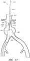
- Figure 1 is a partial cross sectional view of a patient's vasculature illustrating an endoluminal prosthesis deployed in the desired position within the patient's vasculature.
- Figure 1 shows an endoluminal prosthesis deployed in a patient's aorta 10.
- An aneurysmal sac 10A is also shown.
- Figure 2 is a side view of the endoluminal prosthesis 20 illustrated in Figure 1 .
- the endoluminal prosthesis 20 illustrated in Figures 1 and 2 has a main graft body 22, a first fenestration 24, and a second fenestration 26.
- the main graft is a bifurcated graft having a first bifurcated branch 28 and a second bifurcated branch 30 for placement in the ipsilateral and contralateral iliac arteries.
- the main graft body 22 has a generally cylindrical, tubular shape.
- the endoluminal prosthesis 20 can be formed from any suitable material, such as, but not limited to, ePTFE.
- the endoluminal prosthesis 20 is formed from an expandable material.
- the endoluminal prosthesis 20 is formed such that the main graft body 22 can be sized to be larger than the target vessel into which the main graft body 22 is to be deployed.
- the target vessel can be the aortic artery, and the endoluminal prosthesis can be deployed so as to span across an aneurysm in the abdominal aortic.
- the diameter of the graft body (such as without limitation the main graft body 22) or an enlarged portion of any embodiment of a graft body disclosed herein can be approximately 30% larger than the diameter of the target vessel or the diameter of the non-enlarged portion of the graft body.
- the diameter of the graft body (such as without limitation the main graft body 22) or an enlarged portion of any embodiment of a graft body disclosed herein can be less than approximately 20%, or from approximately 20% to approximately 50% or more, or from approximately 25% to approximately 40% larger than the target vessel or the diameter of the non-enlarged portion of the graft body, or to or from any values within these ranges.
- At least a portion of the graft material adjacent to the one or more fenestrations or openings can be free to translate in a circumferential or axial direction relative to the stent that the graft is supported by.
- particular portions such as the end portions of the graft material can be sutured or otherwise fastened to the stent, while a mid-portion of the graft having one or more fenestrations therethrough can be unattached to the stent so that such mid portion can be free to translate relative to the stent and, hence, permit the adjustability of the fenestrations relative to the stent.
- the fenestrations can be adjusted to align with the ostium of the patient's branch vessels.
- the diameter of the main graft body 22 configured for placement in an approximately 26 mm vessel can be approximately 34 mm in diameter. Therefore, the diameter of the main graft body 22 can be approximately 8 mm larger than the diameter of the target vessel.
- the diameter of the main graft body 22 can be between approximately 2 mm and approximately 14 mm, or between approximately 4 mm and approximately 12 mm, or between approximately 6 mm and approximately 10 mm larger than the diameter of the target vessel, or to or from any values within these ranges.
- the oversized diameter of the main graft body 22 can provide excess or slack graft material in the main graft body 22 such that the fenestrations 24, 26 can each be moved in an axial, rotational, or angular direction, or a combination thereof to align the fenestrations 24, 26 with the branch vessels arteries, as will be described in greater detail below.
- two or more fenestrations can be formed in the main graft body 22 at any desired location.
- the two fenestrations 24, 26 can be formed at generally diametrically opposed locations.
- any number of fenestrations can be formed in the main graft body 22 at any desired locations.
- scallops or cutouts can be formed in the distal end portion or at any suitable location in the main graft body 22, the scallops or cutouts being configured to prevent obstruction of other arteries branching off of the main vessel into which the main graft body 22 is to be deployed.
- an additional fenestration 32 can be formed in a distal portion of the main graft body 22. The fenestration 32 can be formed so as to align with a patient's SMA.
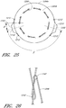
- Figure 3 is a cross-sectional view of the endoluminal prosthesis 20 deployed in the patient's anatomy, taken at 3-3 in Figure 1 , as it might appear before the fenestrations 24, 26 have become aligned with the respective branch vessels, for example renal arteries 12, 14.
- the main graft body 22 (which can be oversized) has been deployed in the target vessel.
- the main graft body 22 can have a larger diameter than the vessel diameter, folds, wrinkles, or other undulations (collectively referred to as folds) 34 can form in the main graft body 22 about the circumference of the main graft body 22.
- the folds 34 can form in the main graft body 22 as a result of the fact that there can be excess or slack material in the main graft body 22 after the main graft body 22 has been deployed in the target vessel.
- At least a portion of the main graft body 22 can have undulations, folds, bends, corrugations, or other similar features in the axial direction therein when the main graft body 22 is in a relaxed state (i.e., before the graft has been deployed).
- a middle portion of the graft can have undulations, folds, bends, corrugations or other similar features while the distal or upstream portion defines a smooth contour
- Figure 4 is a cross-sectional view of the endoluminal prosthesis 20 deployed in the patient's anatomy, taken at 3-3 in Figure 1 , after the fenestrations 24, 26 have become aligned with the respective branch vessels.
- the oversized main graft body 22 is aligned with the patient's anatomy by the fenestration 24 following a angiographic or guide catheter over which it is threaded to align with the respective branch vessel as the main body is deployed, but after the branch vessel guidewires are positioned in the branch vessels.
- the fenestration 24 as it moves closer to the fenestration 26, causes a gathering of slack material or folds 34 in a first portion 22a of the main graft body 22 and partially or fully removing the slack material or folds from a second portion 22b of the main graft body 22.
- a covered stent, a bare wire stent, or any other suitable stent or anchoring device can be deployed within the main graft to secure the graft in the desired location (not illustrated).
- a bare metal stent deployed within the main graft body 22 can compress the folds 34 that are formed in the main graft body 22, if any, against the wall of the vessel and secure the main graft body 22 and the fenestrations 24, 26 in the desired locations.
- a supra renal stent can be deployed at a distal or upper portion of the main graft body to secure the distal or upper portion of the main graft body in the desired location within the patient's vasculature, and one or more axial springs can be anchored to the main graft body to provide axial or column strength to the main graft body.
- the springs can have a helical shape, as illustrated, and can have any suitable size, length, pitch, or diameter. However, such helical shape is not required.
- the springs can have any suitable shape, including a straight, flat, round, or non-round shape.
- the springs can be formed from any suitable biocompatible material, such as without limitation stainless steel, Nitinol, or suitable metallic or polymeric materials.
- Provisional Application 61/409,504 entitled APPARATUS AND METHOD OF PLACEMENT OF A GRAFT OR GRAFT SYSTEM, filed November 2, 2010, can be used, with or without modification, in place of or in combination with any of the features or details of any of the grafts, stents, prostheses, or other components or apparatuses disclosed herein. Similarly, any of the features, components, or details of the delivery apparatuses and deployment methods disclosed in U.S. Patent Application Nos.
- 12/496,446 , 12/390,346 , and 12/101,863 can be used, with or without modification, to deploy any of grafts, stents, or other apparatuses disclosed herein, or in combination with any of the components or features of the deployment systems disclosed herein.
- Figure 5A is a side view of a catheter system 1000 comprising an introducer catheter 1002 (also referred to as an introducer) and a delivery catheter 1004.
- the delivery catheter 1004 can be configured for the delivery of an endoluminal prosthesis, including without limitation any endoluminal prosthesis embodiment or arrangement disclosed herein or any other suitable prosthesis, or for any other suitable use.
- Figure 5B is an oblique view of a catheter system 1000 illustrated in Figure 5A , showing an outer sheath 1006 of the delivery catheter 1004 in a partially retracted position.
- the outer sheath 1006 can be used to constrain at least a portion of a prosthesis 1010.
- the prosthesis 1010 can have any of the same features, components, or other details of any of the other prosthesis embodiments or arrangements disclosed herein, including without limitation the embodiments of the prosthesis 1200 described below.
- the prosthesis 1010 can have any number of stents or other support members, connectors, grafts, cuts, fenestrations, or other suitable components or features.
- distal refers to the end of the prosthesis that is further from the patient's heart
- proximal refers to the end of the prosthesis that is closer to the patient's heart.
- distal refers to the end of the catheter system that is further from the surgeon or medical practitioner using the catheter system
- proximal refers to the end of the catheter system that is closer to the surgeon or medical practitioner.
- a distal sheath 1012 (also referred to herein as a first restraint or first restraining means) can be used to constrain a proximal portion of the stent graft 1010.
- the distal sheath 1012 can be supported by (connected to) a distal tip 1014 of the catheter system 1000.
- the distal tip 1014 can comprise an atraumatic material and design.
- the distal tip 1014 and, hence, the distal sheath 1012 can be attached to an inner tube 1016 to control the position of the distal tip 1014 and the distal sheath 1012 relative to an inner core 1020 of the delivery catheter 1004.
- the inner core 1020 can be rotatable relative to the outer sheath 1006 so that a prosthesis supported by the delivery catheter 1004 can be rotated during deployment.
- the inner tube 1016 can be slidably positioned coaxially within a lumen in an outer tube 1018 that can connect a support member 1022 to the inner core 1020.
- the outer tube 1018 can be connected to an opening or partial lumen 1019 in the inner core 1020 so as to be axially and rotationally fixed to the inner core 1020.
- the catheter system 1000 can be configured such that advancing the inner tube 1016 relative to an inner core 1020 of the delivery catheter 1004 causes the distal sheath 1012 to advance relative to the prosthesis 1010, causing the proximal portion of the prosthesis 1010 to be deployed.
- the prosthesis 1010 (or any other prosthesis disclosed herein) can be at least partially self-expanding such that, as the tubular distal sheath 1012 is advanced relative to the prosthesis 1010, a proximal portion of the prosthesis 1010 expands against a vessel wall.
- only some segments or portions of the prosthesis 1010 such as, portions of the prosthesis axially adjacent to enlarged graft portions of the prosthesis, can be configured to be self-expanding.
- the inner core 1020 can be slidably received within the outer sheath 1006 of the delivery catheter 1004.
- the outer sheath 1006 of the delivery catheter 1004 can be longer than an introducer sheath 1008 of the introducer catheter 1002.
- a clip 1007 can be supported by the outer sheath 1006 to limit the range of axial movement of the outer sheath 1006 relative to the introducer catheter 1002.
- a core assembly 1021 can be connected to a proximal end portion of the inner core 1020, the core assembly 1021 having a reduced cross-sectional profile so as to permit one or more sheath members, fenestration alignment components (also referred to herein as fenestration alignment components), or other tubular or other components to pass through the main body of the delivery catheter 1004 and be advanced into one or more lumen within the inner core 1020.
- the inner core 1020 can be configured to accommodate the insertion of such sheath members, fenestration alignment components, or other tubular components into the lumen of the inner core 1020.
- a proximal end portion of the core assembly 1021 can comprise a handle member 1023 that is positioned outside a proximal end portion of the delivery catheter 1004 so as to be accessible by a user.
- the handle member 1023 can be configured to permit a user to axially or rotationally adjust the position of the inner core 1020 relative to the outer sheath 1006.
- the inner core 1020 can extend proximally past the proximal end portion 1004a of the delivery catheter system 1004 so that a user can adjust and/or change the axial and/or radial position of the inner core 1020 and, hence, the prosthesis 1010, relative to the outer sheath 1006.
- the inner tube 1016 can extend proximally past the proximal end portion 1004a of the delivery catheter 1004 and a proximal end portion 1021a of the core assembly 1021 so that a user can adjust and change the position of the inner tube 1016 relative to the inner core 1020.
- the prosthesis 1010 supported by the catheter system 1000 can be exposed and, potentially, deployed.
- a distal portion of the prosthesis 1010 can be exposed and deployed by retracting the outer sheath 1006 relative to the inner core 1020 or distally advancing the inner core 1020 relative to the outer sheath 1006, causing at least a portion of the distal portion of the prosthesis 1010 to self-expand.
- the prosthesis 1010 can be configured to have radially self-expanding support members therein along only a portion or portions of the prosthesis 1010.
- a graft of the prosthesis 1010 can be radially unsupported at or adjacent to fenestrations formed in the graft.
- at least the distal portion of the prosthesis 1010 can be constrained within a sheath, such as a peelable sheath. Embodiments of the sheath will be described in greater detail below.
- the delivery catheter 1004 can also have one or more branch or guide sheaths 1024 supported thereby.
- the delivery catheter 1004 can have three or more branch sheaths 1024.
- Such a configuration can be used for deploying branch stents into one or more branch vessels in the thoracic aorta.
- Each of the one or more branch sheaths 1024 can be configured to be slidably supported within one or more lumen 1025 formed in the inner core 1020 so that each of the one or more branch sheaths 1024 can be axially advanced or retracted relative to the inner core 1020.
- the delivery catheter 1004 can be configured such that the branch sheaths 1024 can be rotationally adjusted or twisted relative to the inner core 1020.
- each branch sheath 1024 can be positioned within the delivery catheter 1004 such that, in the loaded configuration wherein a prosthesis 1010 is supported (compressed) within the delivery catheter 1004, each branch sheath 1024 is pre-positioned so as to be advanced through a fenestration or branch graft of the prosthesis 1010.
- Each branch sheath 1024 can be positioned within the delivery catheter 1004 such that a distal end portion of each branch sheath 1024 projects past an end portion of the inner core 1020 and is constrained within the outer sheath 1006. As illustrated in Figures 5A-5B , in this configuration, the distal end portion of each branch sheath 1024 can be exposed by retracting the outer sheath 1006 relative to the inner core 1020 and/or the branch sheaths 1024.
- the delivery catheter 1004 can have one or more fenestration alignment components 1026 supported thereby.
- the one or more fenestration alignment components 1026 can be slidably received within one or more lumen 1027 formed in the inner core 1020.
- the one or more fenestration alignment components 1026 can each have an end portion 1026a that can be sized and configured to surround an outer surface of each of the branch sheaths 1024.
- the end portion 1026a of each fenestration alignment component 1026 can have, an open or closed annular or circular shape and can be of sufficient size and stiffness to permit a user to engage a fenestration or branch graft formed in or supported by a main body of the prosthesis 1010.
- a user can independently or collectively axially advance the fenestration alignment component 1026 over the branch sheaths 1024 such that the end portion 1026a of each fenestration alignment component 1026 contacts the edge or surface adjacent to and surrounding the fenestration or branch graft of the prosthesis 1010 and pushes the fenestration or branch graft toward an ostium of the target branch vessel of the patient's vasculature.
- each of the one or more fenestration alignment components 1026 is configured to be slidably supported within a lumen formed in the inner core 1020 so that each of the one or more fenestration alignment components 1026 can be axially advanced relative to the inner core 1020.
- the delivery catheter 1004 can be configured such that the fenestration alignment components 1026 can be axially or rotationally adjusted or twisted relative to the inner core 1020, for increased maneuverability of the fenestration alignment components 1026.
- each fenestration alignment component 1026 can be positioned within the delivery catheter 1004 such that, in the loaded configuration wherein a prosthesis 1010 is supported (compressed) within the delivery catheter 1004, each fenestration alignment component 1026 is pre-positioned so that the end portion 1026a of each fenestration alignment component 1026 is positioned distal to the end portion of the inner core 1020. In the loaded configuration, each fenestration alignment component 1026 can be positioned such that the end portion 1026a of each fenestration alignment component 1026 is located within the main lumen of the main body of the prosthesis 1010.
- the branch sheaths 1024 and fenestration alignment components 1026 can have any suitable size and can be made from any suitable material.
- the branch sheaths 1024 can have an approximately 6.5 French diameter, or from an approximately 5 Fr diameter or less to an approximately 8 Fr diameter or more, or to or from any values within this range.
- the fenestration alignment components 1026 can be formed from stainless steel, Nitinol, or any other suitable metallic or non-metallic material, and can have a thickness suitable to prevent the fenestration alignment components 1026 from buckling when axially advanced against a portion of the prosthesis 1010.
- the fenestration alignment components 1026 can have an approximately 1 Fr diameter, or between approximately a 1 Fr and approximately a 4 Fr diameter.
- the fenestration alignment component or catheters can be formed from a .035 in guidewire or otherwise have a .035 in diameter.
- the catheter system 1000 can be configured such that the distal sheath 1012 can be advanced relative to the inner core 1020 and the prosthesis 1010, to expose a proximal portion of the prosthesis 1010.
- advancing the distal sheath 1012 can be accomplished by advancing the inner tube 1016 connected to the distal tip 1014 and the distal sheath 1012, so that the distal sheath 1012 releases the proximal portion of the prosthesis 1010.
- Other details regarding the distal sheath 1012 or methods of using the distal sheath can be found in U.S. Patent No. 6,953,475 .
- Figures 6 and 7 are oblique and exploded views, respectively, of the introducer catheter 1002 shown in Figure 5A .
- the introducer catheter 1002 can have any of the features or components of any of the embodiments disclosed in U.S. Patent Application No. 12/496,446 .
- the introducer 1002 can have a main body 1030, a threadably engageable hub portion 1032, a threaded cap 1034 configured to threadably engage with a threaded distal end portion 1030a of the main body 1030 so as to secure the outer sheath 1006 to the main body 1030.
- the outer sheath 1006 can have a flanged end portion 1036 secured thereto or integrally formed therewith.
- the main body 1030 can support a seal assembly 1040 therein to seal around the inner core 1020 of the delivery catheter 1004 and/or other components of the catheter system 1000.
- a threaded end member 1042 having a threaded proximal end portion 1042a can be supported by the main body 1030.
- An annular seal member 1046 can be supported by the main body 1030 of the introducer catheter 1002.
- the introducer catheter 1002 can be configured such that the seal member 1046 can be adjusted to provide an additional seal around the inner core 1020 of the delivery catheter 1004 by threadably engaging the hub portion 1032.
- the seal assembly 1040 and seal member 1046 can have any of the details, features, or components of any of the embodiments of the introducer catheter described in U.S. Patent Application No. 12/496,446 .
- a tube assembly 1048 can be supported by the main body 1030 of the introducer catheter 1002 so as to provide an orifice or access port into the main body 1030.
- the tube assembly 1048 can be used to flush the introducer catheter 1002 with saline or other suitable substances at any stage, such as but not limited to prior to the advancement of an endoluminal prosthesis through the introducer catheter 1002 and/or delivery catheter 1004, or prior to other procedures for which another type of delivery catheter may be used.
- the tube assembly 1048 can support any suitable medical connector and/or valve on the distal end thereof.
- Figures 8 and 9 are oblique and exploded views, respectively of the delivery catheter 1004 shown in Figure 5A .
- Figure 10 is a sectional view of a portion 10-10 of the delivery catheter 1004 shown in Figure 5A .
- Figure 11A is a sectional view of the delivery catheter 1004 shown in Figure 5A , taken at 11A-11A shown in Figure 10.
- Figure 11B is a sectional view of the delivery catheter 1004 shown in Figure 5A , taken at 11B-11B shown in Figure 10 .
- the delivery catheter 1004 can have a main body 1050 that can support the inner core 1020 and/or core assembly 1021, one or more access ports 1052 for the one or more branch sheaths 1024, and one or more access ports 1054 for the one or more fenestration alignment components 1026.
- the access ports 1052, 1054 can be configured to sealingly tighten around the branch sheaths 1024 or the fenestration alignment components 1026, and to constrict around the branch sheaths 1024 or the fenestration alignment components 1026 so as to substantially axially secure the branch sheaths 1024 or the fenestration alignment components 1026.
- a sealable cap assembly 1051 can be threadably engaged with the main body 1050 of the delivery catheter 1004.
- the cap assembly 1051 can be configured such that, when a user tightens the cap assembly 1051 relative to the main body 1050 of the delivery catheter 1004, the core assembly 1021 and/or inner core 1020 will be axially and/or rotational secured to the main body 1050 of the delivery catheter 1004.
- a tube assembly 1059 can be supported by the main body 1050 of the delivery catheter 1004 so as to provide an orifice or access port into the main body 1050.
- the tube assembly 1059 can be used to flush the delivery catheter 1004 with saline or other suitable substances.
- the tube assembly 1059 can support any suitable medical connector and/or valve on the distal end thereof.
- the support member 1022 can be connected to a distal end portion of the outer tube 1018 so as to be axially engaged by the outer tube 1018.
- the support member 1022 can have a substantially cylindrical shape and can be sized to fit within the inner lumen of a main body of the prosthesis 1010 when the prosthesis 1010 is in a constrained configuration.
- the prosthesis 1010 in the loaded configuration, can be positioned over the support member 1022 so that a proximal portion of a main body of the prosthesis 1010 is positioned distally of the support member 1022 and so that a distal portion of a main body of the prosthesis 1010 is positioned proximally of the support member 1022.
- a proximal end portion 1012a of the distal sheath 1012 can be positioned over a distal portion 1022a of the support member 1022, and a distal end portion 1006a of the outer sheath 1006 over a proximal portion 1022b of the support member 1022.
- one or more tab members 1074 can be supported by the outer tube 1018.
- the one or more tab members 1074 can be configured to increase the rotational engagement of the constrained prosthesis 1010 relative to the outer tube 1018 so that the constrained prosthesis 1010 can be rotated with greater accuracy during deployment.
- the one or more tab members 1074 can have a generally flat, plate-like shape, such as is illustrated in Figure 8 .
- the one or more tab members 1074 can be formed from a suitable polymeric or metallic material.
- the one or more tab members 1074 can comprise one or more radiopaque features or be formed from a radiopaque material to improve the visibility and alignability of the delivery catheter 1004 under fluoroscopy during deployment of the prosthesis 1010.
- the one or more tab members 1074 can be similar to any of the embodiments of the torsion tab (such as the torsion tab 196) disclosed in U.S. Patent Application No. 12/101,863 ,.
- the one or more tab members 1074 can be integrally formed with the outer tube 1018, or secured thereto such as by thermal bonding, adhesive bonding, and/or any of a variety of other securing techniques known in the art.
- the main body portion of the prosthesis 1010 can be constrained by a peelable sheath or by the outer sheath 1006 such that the prosthesis 1010 is engaged with the one or more tab members 1074.
- the one or more tabs 1074 can engage a stent or other portion of an endoskeleton of the prosthesis 1010, or, can engage the material of the graft 1204 surrounding the tab member 1074 so that the prosthesis 1010 can substantially rotate with the inner core 1020 of the deployment catheter 1004.
- Figure 12 is a side view of the catheter system 1000 showing the outer sheath 1006 in a partially retracted position, similar to the configuration shown in Figure 5B .
- Figure 13 is an enlarged side view of the portion 13-13 of the catheter system shown in Figure 12 .
- the mid portion of the prosthesis 1010 adjacent to the one or more fenestrations 1011 and/or the distal portion 1010a of the prosthesis can be constrained within a peelable sheath 1060.
- the peelable sheath 1060 can have a release wire 1062 threadably advanced through a plurality of openings 1064 formed along at least a portion of the sheath 1060.
- the peelable sheath 1060, release wire 1062, and openings 1064 can have any of the same features, materials, or other details of the similar components disclosed in U.S. Patent Application No. 12/101,863 .
- the release wire 1062 can be slidably received within a lumen in the inner core 1020 so that a user can retract the release wire 1062 by grasping and retracting a proximal portion of the release wire 1062 positioned outside the patient's body.
- the mid portion of the prosthesis 1010 adjacent to the one or more fenestrations 1011 and/or the distal portion 1010a of the prosthesis can be constrained within one or more tubular sheaths, such as the outer sheath 1006 (also referred to herein as a second restraint or second restraining means) and/or distal sheath 1012 such that additional restraining means such as the sheath 1060 are not required (not illustrated). Therefore, any of the embodiments disclosed herein having the optional sheath 1060 should be understood to be configurable to not use the sheath 1060 to restrain one or more portions of the prosthesis 1010.
- the prosthesis 1010 can be configured such that the mid portion of the prosthesis 1010 adjacent to the one or more fenestrations 1011 is not radially supported by a stent, connectors, struts, or any other similar structure such that, when the outer sheath 1006 is partially retracted, the mid portion of the prosthesis does not self-expand.
- the prosthesis 1010 can have one or more openings 1011 formed therein.
- the fenestrations or openings 1011 can be formed in the prosthesis 1010 at diametrically opposing positions.
- one or more of the openings 1011 can be formed in the prosthesis 1010 at a position that is angularly offset from the diametrically opposing position.
- the sheath 1060 can have one or more openings 1061 formed therein, the openings 1061 being positioned adjacent to the similar number of openings 1011 formed in the prosthesis.
- the catheter system 1000 can be configured such that the sheaths 1024 are advanced through the openings 1011 formed in the prosthesis 1010 and the openings 1061 formed in the sheath 1060, when the prosthesis 1010 is loaded within the catheter system 1000.
- the prosthesis 1010 can be efficiently packed within the outer sheath 1006 so as to surround the sheaths 1024 and efficiently fill the space within the outer sheath 1006.
- the prosthesis 1010 can be loaded within the outer sheath 1006 so that the sheaths 1024 are advanced between many of the struts, bends, loops, and other features that the stent can comprise, thereby permitting the sheaths 1024 sufficient space to be loaded within the outer sheath 1006 so that the lumen of the sheaths 1024 are not compressed or collapsed in the loaded state.
- the graft can be formed from a bidirectionally expanded, layered PTFE material have thin walls to further increase the space efficiency of the prosthesis 1010.
- the peelable sheath 1060 can have one or more release wires 1062 (two being shown) advanced through openings or perforations 1064 formed in the sheath 1060 along two sides of the sheath 1060.
- the release wires 1062 can be configured to tear the sheath 1060 along two lines of perforations 1064 and/or scores formed along two sides of the sheath 1060, so that the sheath 1060 can be removed from the prosthesis 1010 while the sheaths 1024 are advanced through the fenestrations 1011, 1061, respectively, in the prosthesis 1010 and sheath 1060.
- each of the two release wires 1062 can be secured to a proximal end portion 1060a of the sheath 1060, so that both halves of the sheath 1060 can be retracted through the outer sheath 1006.
- the catheter system 1000 can be configured to only have one release wire 1062 threadably advanced through the sheath 1060.
- Figure 14 is an enlarged side view of the catheter system 1000 shown in Figure 5A , defined by curve 14-14 shown in Figure 12 , showing the outer sheath 1006 in a partially retracted position and the distal sheath 1012 in a partially advanced position.
- the perforations 1064 formed in the sheath 1060 can be arranged along an axial line along the length of the portion of the sheath 1060 from the fenestrations 1061 to the distal end of the sheath 1060, and also arranged to split the sheath 1060 between the two fenestrations 1061 formed in the sheath 1060. As illustrated in Figure 14 , the perforations 1064 formed in the sheath 1060 arranged along the length of the sheath 1060 can be positioned to tear the sheath 1060 from one of the fenestrations 1061 to the distal end 1060b of the sheath 1060, and also to circumferentially tear the sheath 1060 between the fenestrations 1061.
- the catheter system 1000 can be configured such that a proximal portion 1010b of the prosthesis 1010 can be deployed by axially advancing the inner tube 1016 relative to the inner core 1020 of the delivery catheter 1004 and, hence, the prosthesis 1010.
- the prosthesis 1010 can be self-expanding such that removing the radial constraint provided by the distal sheath 1012 can cause the portion of the prosthesis 1010 constrained by the inner tube 1016 to expand toward the vessel wall.
- the proximal portion 1010b of the prosthesis 1010 can be deployed in this manner before the distal portion 1010a of the prosthesis 1010 is deployed, or simultaneously with the deployment of the distal portion 1010a of the prosthesis 1010.
- the proximal portion 1010b of the prosthesis 1010 can be deployed in this manner after the distal portion 1010a of the prosthesis 1010 is deployed.
- Figure 15 is a side view of the catheter system 1000 shown in Figure 5A , showing the outer sheath 1006 in a partially retracted position and one branch sheath 1024' and one fenestration alignment component 1026' in a partially advanced position.
- the branch sheath 1024' can be advanced relative to the inner core 1020, the prosthesis, and the second branch sheath 1024" by advancing a proximal portion of the branch sheath 1024' in the direction of arrow A1 in Figure 15 through the access port 1052' at the proximal end of the delivery catheter 1004.
- the second branch sheath 1024" can be advanced relative to the inner core 1020, the prosthesis, and the first branch sheath 1024' by advancing a proximal portion of the branch sheath 1024" through the access port 1052" at the proximal end of the delivery catheter 1004.
- either of the fenestration alignment components 1026', 1026" can be advanced relative to the branch sheaths 1024', 1024" by advancing the respective fenestration alignment component 1026 through the respective access port 1054.
- the fenestration alignment component 1026' can be advanced by advancing the proximal portion of the fenestration alignment component 1026' in the direction of arrow A2 in Figure 15 .
- Figure 16 is a sectional view of a portion of a patient's vasculature, showing the delivery catheter 1000 being advanced through a patient's abdominal aorta over a guidewire 1070 positioned within a patient's vasculature.
- the delivery catheter 1000 can be advanced through a prosthesis 1080 (which can be a bifurcated prosthesis) deployed within the patient's vasculature.
- Figure 17 is a sectional view of a portion of a patient's vasculature, showing the delivery catheter 1000 and an angiographic catheter 1065 being advanced through a branch sheath 1024 of the delivery catheter toward a target branch vessel.
- an outer sheath 1006 of the catheter system 1000 has been retracted relative to the inner core (not shown) and the prosthesis 1010, exposing a middle portion of the prosthesis 1010 (i.e., a portion of the prosthesis 1010 radially adjacent to the one or more fenestrations 1011) and the branch sheaths 1024a, 1024b.
- a suitable angiographic catheter 1065 can be advanced through the lumen of either or both of the branch sheaths 1024a, 1024b and directed into the target branch vessel or vessels.
- a user can rotate the inner core 1020 to approximately rotationally align the fenestrations 1011 of the prosthesis 1010 or the branch sheaths 1024 with the branch vessels.
- the optional sheath 1060 can constrain the mid and distal portions of the prosthesis 1010 such that, when the outer sheath 1006 is retracted, the mid and distal portions of the prosthesis 1010 do not self-expand.
- the mid portion of the prosthesis 1010 radially adjacent to the one or more fenestrations 1011 can be unsupported by any stents 1254.
- the prosthesis 1010 can be configured such that there is no radial force or support provided to the mid portion of the prosthesis 1010, or such that the mid portion of the prosthesis 1010 will not be biased to self-expand when the outer sheath 1006 is retracted.
- some embodiments can be configured such that no additional restraint in addition to, for example, the outer sheath 1006, is required. Therefore, only the outer sheath 1006 and the distal sheath 1012 can be used to restrain the prosthesis 1010.
- the outer sheath 1006 can be partially retracted to release the sheaths 1024 so that one or more angiographic catheters 1065 can be advanced through the sheaths 1024 and into the target branch vessels before the proximal and distal portions of the prosthesis 1010 are released from the deployment catheter 1004.
- the angiographic catheter 1065 can be configured such that an end portion thereof is biased to have a curved disposition (shape), as is well known in the art.
- an angiographic catheter 1065 is being advanced relative to the branch sheath 1024a and into the target branch vessel, in this case a renal artery.
- the delivery catheter 1000 can be configured such that an angiographic catheter can be advanced through the desired branch sheath 1024 and into the target vessel without retracting the outer sheath 1006.
- either or both of the branch sheaths 1024 can be independently or simultaneously advanced over the angiographic catheters 1065 into the target branch vessels, as is illustrated in Figure 18 .
- the branch sheaths 1024, the fenestrations 1011, 1061 formed in either the prosthesis 1010 or the sheath 1060, respectively, and/or any other components or features of the delivery catheter 1000 can have radiopaque markers or other indicators to assist a medical practitioner in the deployment procedures described herein or other suitable deployment procedures.
- a proximal portion 1010b of the prosthesis 1010 can be deployed by axially advancing the distal sheath 1012 relative to the inner core 1020 and the prosthesis 1010.
- the prosthesis 1010 can be axially and rotationally secured to the outer tube 1018, which can be axially and rotationally secured to the inner core 1020, such that advancing the distal sheath 1012 relative to the inner core 1020 will advance the distal sheath 1012 relative to the prosthesis 1010.
- the distal sheath 1012 can be advanced relative to the inner core 1020 and the prosthesis 1010 by advancing the inner tube 1016 relative to the inner core 1020, the inner tube 1016 being axially engaged with the distal tip 1014 which can support the distal sheath 1012.
- Figure 20 is a sectional view of a portion of a patient's vasculature, showing a peelable sheath 1060 being removed from the distal portion 1010a of the prosthesis 1010 so as to deploy a distal portion 1010a of the prosthesis 1010.
- the sheath 1060 can be removed by axially retracting a release wire 1062, which can be looped or other otherwise threaded through openings or perforations 1064 formed in the sheath material.
- the release wire 1062 can be configured to tear through the sheath material between the perforations 1064, thereby permitting the self-expanding prosthesis 1010 to expand toward the vessel walls.
- the prosthesis 1010 can be configured to be restrained within the outer sheath 1006 and the distal sheath 1012 such that an additional restraint, such as the peelable sheath 1060, is not required.
- a distal portion 1060a of the sheath 1060 can be torn by the release wire 1062 before a proximal portion 1060b of the sheath 1060 is torn by the release wire so that a proximal portion 1010b of the prosthesis (i.e., adjacent to the proximal portion 1060a of the sheath 1060) can be deployed before a distal portion 1010a of the sheath 1010.
- a proximal portion 1060b or a middle portion of the sheath 1060 can be torn by the release wire 1062 before a distal portion 1060a of the sheath 1060 is torn by the release wire (not illustrated).
- the release wire 1062 can be secured to the proximal portion 1060b or other suitable portion of the sheath 1060 such that, after the sheath 1060 has been torn, the sheath 1060 can be removed through the delivery catheter 1000 by continuing to axially retract the release wire 1062 relative to the prosthesis 1010.
- a distal portion 1010a of the prosthesis 1010 (i.e., the downstream portion of the prosthesis 1010) can be deployed within an opening of an adjacent prosthesis, such as without limitation the bifurcated prosthesis 1080 illustrated in Figure 20 .
- the delivery catheter 1000 or any other delivery catheter described herein can be used to deploy any suitable prosthesis, including a bifurcated prosthesis or otherwise, in any portion of a patient's vasculature.
- the prosthesis 1010 can be a bifurcated prosthesis.
- Figure 21 is a sectional view of a portion of a patient's vasculature, showing a fenestration alignment component 1026 contacting and pushing an inner wall of the prosthesis 1010 adjacent to a fenestration 1011 toward an ostium of the target branch vessel.
- the fenestration alignment component 1026 can be advanced through a lumen in the inner core 1020 to push the fenestration 1011 of the prosthesis 1010 over the branch sheath 1024 and into approximate alignment with the ostium of the branch vessel.
- the catheter system 1000 can be configured to not have a fenestration alignment component 1026, and can accordingly be configured to deploy a fenestrated graft without the use of such a component.
- a covered or uncovered branch stent 1084 can be deployed in the branch vessel by advancing the branch stent 1084 through the branch sheath 1024 using a suitable catheter, such as a renal stent catheter, into the target vessel, after the angiographic catheter has been removed from the branch sheath 1024.
- the stent 1084 can be supported on an inflation balloon 1086, which can be supported by a guidewire 1088.
- the guidewire 1088 can be configured to have an inflation lumen therein, to inflate the balloon 1086 and expand the branch stent 1084 in the target location after the branch sheath 1024 has been at least partially retracted so as to not interfere with the expansion of the branch stent 1084, as illustrated in Figure 23 .
- the inflation balloon 1086 can be configured to expand and flare a portion of the stent 1084 within or to the inside of the fenestration 1011 formed in the prosthesis.
- the fenestration alignment component 1026 described above can be configured to be supported within a renal or branch stent delivery catheter.
- the fenestration alignment component 1026 can be configured to be supported within a modified renal stent catheter, such as the renal stent catheter illustrated in Figure 22 .
- the fenestration alignment component 1026 can be configured to only partially surround the branch sheath 1024 or the branch stent delivery catheter. In this configuration, the fenestration alignment component 1026 can be configured to be entirely positioned within and advanceable through a lumen of the branch sheath 1024 or the branch stent delivery catheter.
- the fenestration alignment component 1026 can have an expandable end portion that can automatically expand when the end portion is advanced past the end of the lumen, so as to enable the end portion to snare or engage the graft material surrounding the fenestration.
- the branch stent delivery catheter can be configured to have a snare, protrusion, or other object tethered to the balloon or stent, or to be projecting from an outside surface thereof to snare or engage the graft material adjacent to the fenestration, so as to cause the fenestration to be advanced toward the ostium as the branch stent delivery catheter is advanced through the fenestrations.
- the branch stent delivery catheter can have a biased wire member supported on an outside surface of the branch stent delivery catheter that is biased to expand when the wire member is advanced past the end of the branch sheath 1024.
- the wire member can expand to a size that is larger than the size of the fenestration.
- the wire member can be supported at a position that is offset from an end of the branch stent delivery catheter.
- the fenestration 1011 in the prosthesis 1010 can expand as the branch stent 1084 is being expanded, to improve the seal between the fenestration 1011 and the branch stent 1084.
- a second expansion balloon can be positioned in the portion of the stent 1084 within or to the inside of the fenestration 1011 to flare that portion of the stent 1084, either with or without removing the first balloon used to expand the main portion of the branch stent 1084.
- Some arrangements are directed to methods of deploying an endoluminal prosthesis, such as without limitation the prosthesis 1010 described above, comprising inserting a delivery catheter such as catheter system 1000 into an artery, exposing one or more branch sheaths 1024, advancing one or more angiographic catheters having one or more guidewires into the one or more branch sheaths 1024 and cannulating the target branch vessels, advancing the one or more branch sheaths 1024 over the angiographic catheters and into the target branch vessels, advancing the wall of the prosthesis adjacent to each of one or more fenestrations in the prosthesis toward the ostium of the target branch vessels, removing the one or more angiographic catheters and/or guidewires, inserting one or more branch stents into the branch vessels, retracting the branch sheaths, expanding the branch stents, and flaring a portion of the branch stents.
- the target branch vessels are the renal arteries.
- Some embodiments are directed to apparatuses for placing a prosthesis across at least one branch vessel, the prosthesis having a distal end, a proximal end, a midsection, and at least one lateral opening in the midsection of the prosthesis.
- the prosthesis can be constrained in a delivery system having a distal and a proximal end.
- the apparatus can comprise a catheter extending from the proximal end of the delivery system through the lateral opening in the prosthesis, wherein a guidewire can be passed from the proximal end of the delivery system through the catheter, into the branch vessel with at least the proximal and distal ends of the prosthesis remaining constrained in the delivery system.
- the prosthesis can be a stent graft.
- FIGs 24A and 24B are oblique views of a prosthesis 1200 comprising one or more fenestrations 1202 formed in the graft 1204, and a stent or support member 1206.
- the graft 1204 is shown in dashed lines in Figure 24B for clarity.
- the prosthesis 1200 can have any of the features, components, or other details of any other prosthesis embodiments disclosed herein such as, prosthesis 1010 described above. Further, any of the features of the prosthesis 1200 can be used in combination with any of the other prosthesis embodiments disclosed herein.
- the graft 1204 can be supported by the stent 1206 along at least a portion of the graft 1204. Further, the graft 1204 can be overlapped and can have stitching or sutures 1208 along one or more edges of the graft 1204, which can improve the tear resistance of the graft 1204 and can improve the connection between the graft 1204 and the stent 1206.
- the graft 1204 can be configured to have excess or slack graft material in at least a portion thereof relative to the stent which supports the graft.
- the excess graft material can form a bulge or other enlargement in the graft 1204 in the approximate location of one or more fenestrations 1202 formed through the graft material.
- the excess or slack material along the circumference of the graft 1204 can allow for circumferential and/or axial movement of the graft material and, hence, the one or more fenestrations 1202, relative to the stent 1206 and the ostium of the patient's branch vessels. Therefore, the diameter of the graft 1204 at and/or adjacent to the location of one or more fenestrations 1202 can be larger than the local diameter of the target vessel. Similarly, the diameter of the graft 1204 at and/or adjacent to the location of one or more fenestrations 1202 can be larger than the diameter of the non-enlarged portion of the graft material.
- the outside surface of the graft 1204 in the enlarged portion 1204a or otherwise can be free from any corrugations or other preformed folds, overlaps, or other similar pre-formed features.
- the graft 1204 can have excess graft material in an axial direction, in addition to or in the alternative of the diametrically enlarged portion.
- the excess or slack material along the length of the graft 1204 can increase the circumferential and/or axial adjustability or movement of the graft material adjacent to the one or more fenestrations 1202 formed in the graft 1204.
- the length of the graft material between the proximal and distal attachment points to the stent 1206 can be longer than that of the stent 1206 between the proximal and distal attachment points.
- the graft material in a mid-portion of the graft 1204, including on either side of the enlarged portion 1204a can have an increased length relative to the stent radially adjacent to such graft portion.
- the enlarged portion and/or excess length of the graft 1204 or any other graft embodiment disclosed herein can be free from any attachment points to the stent or support member which supports the graft 1204.
- the positional adjustability of the fenestrations can be increased because the graft material is free to move in an axial and/or circumferential direction relative to the stent and relative to the ostium of the target branch vessels.
- the enlarged portion and/or excess length of the graft 1204 or any other graft embodiment disclosed herein can be configured to have only a limited number of attachment points to the stent or support member which supports the graft 1204.
- the attachment points can be sufficiently away from the fenestration or opening so as to not substantially affect the adjustability of the fenestration.
- the prosthesis 1010 can be configured such that the enlarged or slack portion of the graft has only a limited number of attachments to a stent or connector (such as connector 1254) away from the fenestrations 1202 so that the adjustability of the enlarged or slack portion is not significantly affected.
- the attachment or attachments to the stent or other support member can be positioned on an opposite side of the graft as compared to the position of the fenestration. In these configurations, the positional adjustability of the fenestrations can be increased because the graft material is substantially free to move in an axial and/or circumferential direction relative to the stent and relative to the ostium of the target branch vessels.
- the graft 1204 can have one or more enlarged portions 1204a having an enlarged diameter relative to the target vessel or relative to one or more non-enlarged portions of the graft 1204, such as portions 1204b, 1204c that can improve the radial and/or axial adjustability of the fenestrations 1202 formed in the enlarged portions 1204a to better accommodate asymmetrically positioned branch vessel ostium.
- the graft 1204 can have an enlarged middle portion 1204a having one or more fenestrations 1202 formed therein, a non-enlarged proximal portion 1204b, and a non-enlarged distal portion 1204c.
- the enlarged portion 1204a of the graft 1204 can have a diameter that is approximately 30% larger than a diameter of the target vessel or the diameter of the non-enlarged portions 1204b, 1204c of the graft 1204.
- the diameter of the enlarged portion 1204a of the graft 1204 can be from approximately 20% or less to approximately 50% or more, or from approximately 25% to approximately 40% larger than the target vessel or the diameter of the non-enlarged portions 1204b, 1204c of the graft 1204, or to or from any values within these ranges.
- the enlarged portion 1204a or portion of the graft 1204 adjacent to the enlarged portion 1204a of the graft 1204 can be sized and configured to be substantially longer (i.e., in the axial direction) than the stent 1206, which can improve the radial and/or axial adjustability of the fenestrations 1202 formed in the enlarged portions 1204a to better accommodate the asymmetric and/or non-uniform positioning of branch vessel ostium.
- the graft 1204 can be longer than the stent 1206 in both the enlarged portion 1204a of the graft 1204 and/or in the portion of the non-enlarged distal portion 1204c of the graft adjacent to the enlarged portion 1204a of the graft 1204.
- the enlarged portion 1204a or portion of the graft 1204 adjacent to the enlarged portion 1204a of the graft 1204 can be sized and configured to be approximately 20% longer in the axial direction than the stent 1206.
- the enlarged portion 1204a or portion of the graft 1204 adjacent to the enlarged portion 1204a of the graft 1204 can be sized and configured to be from approximately 10% to approximately 40% or more longer in the axial direction than the stent 1206.
- FIG 25 is a top view of the prosthesis 1200 of Figure 24 .
- the prosthesis 1200 can have fenestrations 1202 formed in an enlarged portion 1204a of the graft 1204.
- the fenestrations 1202 can be formed at non-diametrically opposed positions. This can improve the alignment of the fenestrations 1202 with the ostium of the target branch vessels, which in general can be located at non-diametrically opposed positions.
- the fenestrations 1202 formed in either the enlarged portion or portions 1204a or non-enlarged portions 1204b, 1204c of the graft 1204, can be angled away from the diametrically opposed position (represented by angle X in Figure 25 ) such that the fenestrations 1202 are separated by an angle (represented by angle Y in Figure 25 ) that is less than 180 degrees.
- the graft 1204 can have two fenestrations 1202 formed at an angle away from the diametrically opposed position (represented by angle X in Figure 25 ) of approximately 15 degrees such that the fenestrations 1202 are separated by an angle (represented by angle Y in Figure 25 ) that is approximately 150 degrees.
- the graft 1204 can have two fenestrations 1202 formed at an angle away from the diametrically opposed position of between approximately 10 degrees or less and approximately 20 degrees or more, such that the fenestrations 1202 are separated by an angle (represented by angle Y in Figure 25 ) that is between approximately 160 degrees and approximately 140 degrees.
- the graft 1204 can have two fenestrations 1202 formed in an enlarged portion 1204a of the graft and wherein the fenestrations 1202 are separated by an angle that is less than 180 degrees, for example approximately 150 degrees.
- positioning the fenestrations 1202 to be separated by an angle that is less than 180 degrees can improve the alignment of the fenestrations 1202 with the ostium of the target branch vessels such that the enlarged portion 1204a of the graft 1204 can be from approximately 20% to approximately 60% greater than the non-enlarged portion 1204b, 1204c of the graft 1204.
- the enlarged portion 1204a of the graft 1204 can be from approximately 20% to approximately 40% greater than the non-enlarged portion 1204b, 1204c of the graft 1204.
- the graft 1204 which can be a bifurcated or other suitably configured graft, can have two fenestrations 1202 formed in an enlarged portion 1204a of the graft, wherein the fenestrations 1202 can be separated by an angle that is less than 180 degrees, and wherein the length of at least a portion of the graft 1204 can be substantially greater than the length of the stent 1206, for example approximately 10% greater than the length of the stent 1206.
- positioning the fenestrations 1202 to be separated by an angle that is less than 180 degrees (such as, for example, approximately 150 degrees) and increasing the length of the graft 1204 to be approximately 10% greater than the length of the stent 1206 can improve the alignment/alignability of the fenestrations 1202 with the ostium of the target branch vessels such that the enlarged portion 1204a of the graft 1204 can be from approximately 10% or less to approximately 20% greater than the non-enlarged portion 1204b, 1204c of the graft 1204.
- the prosthesis 1200 can have reinforced fenestrations 1202 comprising a tubular member 1210 inserted through the fenestration 1202 and stitched to the graft 1204 with one or more sutures 1212.
- the tubular member 1210 can improve the tear resistance of the fenestration 1202 and also improve the sealability between the fenestrations 1202 and the branch grafts and stents deployed within the fenestrations 1202 as well as the pull-out resistance of the branch grafts and stents within the fenestrations 1202.
- This configuration can reduce leakage between the fenestrations 1202 and the branch grafts and stents deployed within the fenestrations 1202. In some embodiments, this configuration can also increase the force required to pull the branch grafts and stents deployed within the fenestrations 1202 out of the fenestrations 1202, thereby reducing the inadvertent axial movement of the branch grafts and stents deployed within the fenestrations 1202.
- the graft 1204 can have a scallop or cut-away 1230 at a proximal end portion 1204b of the graft 1204.
- the cut-away 1230 can be sized and configured to permit unrestricted blood flow through a branch artery, such as the suprarenal and/or the celiac arteries.
- the size of the cut-away 1230 can be based on the anatomy of a patient, or can be sized to accommodate a wide range of vessel anatomies.
- the cut-away 1230 can have a length approximately equal to the length of two stent struts, such as stent strut 1246 described below.
- the graft 1204 can be overlapped and have stitching 1208 along an edge of the cut-away 1230.
- the prosthesis 1200 can have a flared proximal end portion to increase the sealability of such end portion of the prosthesis 1200.
- the prosthesis 1200 can have one or more radiopaque markers, such as but not limited to the annular radiopaque marker 1222 surrounding at least a portion of the fenestration 1202, for improved visibility under fluoroscopy during deployment.
- Any of the radiopaque markers can be formed from gold or platinum, or any suitable material.
- Any of the radiopaque markers can be formed from a suitable non-reinforcing metallic material.
- Figure 27 is a side view of the stent 1206 shown in Figure 24 , viewed along a line that is perpendicular to an axis projecting through a fenestration formed in the graft 1204 (not shown). For clarity, the location of a fenestration 1202 is shown dashed lines.
- Figure 28 is a side view of the stent 1206, viewed along an axis projecting through a fenestration. Again, for clarity, the location of a fenestration 1202 is shown dashed lines.
- the stent 1206 can be formed from one or more wires forming a plurality of loops 1240, which can be closed loops or eyelets, bends 1242, and struts 1246. Some of the bends 1242 can be configured to slide along a portion of the length of a respective strut 1246, to improve the flexibility and bendability of the stent 1206.
- the positioning of the plurality of loops 1240 and bends 1242 can be longitudinally offset or staggered to decrease the collapsed diameter of the prosthesis 1200.
- the stent 1206 can comprise a first stent segment 1250 formed from one or more lengths of wire, a second stent segment 1252 formed from one or more lengths of wire, and one or more connecting members 1254 formed from one or more lengths of wire.
- the first and second stent segments 1250, 1252 can be positioned proximally and distally relative to the location of the fenestration (shown in dashed lines) that can be formed in the graft (not illustrated) that can be supported by the stent 1206.
- the length of the first stent segment 1250 can be sufficient to result in an increased seal zone in the suprarenal portion of the aorta, such as a length that extends to a position adjacent to or overlapping the superior mesenteric artery and/or the celiac artery.
- two connecting members 1254 can be positioned between the first and second stent segments 1250, 1252, and can be sized and offset from one another to provide a significant gap around the position of the fenestrations 1202 to increase the accessibility and adjustability of the fenestrations 1202 during deployment of the prosthesis 1200.
- the connecting members 1254 can have four struts.
- the connecting members 1254 can have three or less struts, or can have five or more struts.
- the connecting members 1254 can have a first connecting member 1254 having fewer struts than a second connecting member 1254.
- Figures 29-31 are oblique, side, and end views, respectively, of a fenestration alignment component 2026 (also referred to as a push member or alignment device) that can be used in any of the delivery catheter embodiments disclosed herein.
- Figure 32 is an oblique view of a delivery catheter 2004 having the fenestration alignment component 2026 of Figure 29 .
- Figure 33 is an exploded view of the delivery catheter 2004 shown in Figure 32 .
- one or more fenestration alignment components 2026 are used in place of one or more fenestration alignment components 1026 described above in any of the delivery catheter embodiments disclosed herein.
- the fenestration alignment component 2026 can serve the same or similar function or be used for the same or similar procedural step or steps as with the embodiments of the fenestration alignment component 1026 described above. Therefore, in claimed embodiments, the fenestration alignment component 2026 is used in any of the procedures, steps, or methods as described above for the fenestration alignment component 1026.
- a user can independently or collectively axially advance the fenestration alignment component 2026 relative to the guide sheath 2024 (which can be the same as the guide sheath 1024 described above) supporting the fenestration alignment component 2026 such that a portion of the fenestration alignment component 2026 engages the fenestration or branch graft of the prosthesis 1010 and pushes the fenestration or branch graft toward an ostium of the target branch vessel of the patient's vasculature.
- the guide sheath 2024 which can be the same as the guide sheath 1024 described above
- a body portion 2027 of the fenestration alignment component 2026 can be slidably positioned around or over an outside surface of the guide sheath 2024. As illustrated in Figures 29 , 31 , and 32 , the body portion 2027 can be cylindrical or tubular. The body portion 2027 can have an inside diameter or size that is greater than an outside diameter or size of the guide sheath 1024 so that the fenestration alignment component 2026 can axially translate relative to the guide sheath 1024.
- the body portion 2027 can have in inner diameter or cross-sectional size of approximately 0.114 in, or from approximately 0.10 in or less to approximately 0.125 inches or more.
- the body portion 2027 can have in outer diameter or cross-sectional size of approximately 0.126 in, or from approximately 0.110 in or less to approximately 0.15 inches or more.
- the body portion 2027 can have a length of approximately 7.1 cm (2.80 in), or from approximately 5 cm (1.97 in) or less to approximately 10 cm (3.94 in), or between any values within the foregoing range.
- the body portion 2027 can be formed from a PEBAX covered alloy coil.
- the body portion 2027 can have a stainless steel coil with a PEBAX tube surrounding the coil.
- the PEBAX can have varying hardness.
- the body portion 2027 can have a PTFE liner surrounding all or a portion of the body portion 2027.
- the body portion 2027 can have a radiopaque marker or band supported thereon, or have portions or components thereof that are made from a radiopaque material.
- a radiopaque band having a length of approximately 0.020 in to approximately 0.060 in can be supported by the body portion 2037.
- the fenestration alignment component 2026 can have a snare, tab, protrusion, or other similar feature supported by the body portion to engage a portion of the prosthesis adjacent to the fenestration.
- the fenestration alignment component 2026 has a tab or protruding portion 2028 (also referred to as a protrusion or projection) projecting from the body portion 2027.
- the protruding portion 2028 can project away from the outside surface of the body portion 2027 by approximately 0.036 in, or from approximately 0.025 in to approximately 0.050 in, or from approximately 0.030 in to approximately 0.045 in, or between any values within any of the foregoing ranges.
- the protruding portion 2028 can define a cross-sectional size (in at least one direction) or diameter that is from approximately 20% or less to approximately 40% or more greater than a cross-sectional size or diameter of the body portion 2027 and/or the fenestration, or between any values within this range.
- the protruding portion or other component or element supported at an end of the body portion 2027 can be inflatable or otherwise moveable between a first position and a second position wherein, in the second position, such component or element projects away from the body portion 2027 more than in the first position.
- the component or element can be a small inflatable balloon positioned at an end of the body portion having a hollow wire in fluid communication with an inner volume thereof.
- the positioning wire 2030 could be made hollow to allow for inflation of the inflatable component or element.
- the protruding portion 2028 can be integrally formed with the body portion 2027, or can be formed separately and adhered to, supported by, or otherwise coupled with the body portion 2027.
- the protruding portion 2028 can have a length of approximately 7 mm (0.276 in) or from approximately 5 mm (0.197 in) or less to approximately 10 mm (0.394 in) or more, or between any values within the foregoing range.
- the protruding portion 2028 can be made from PEBAX.
- the protruding portion 2028 can be made from a PEBAX material having a higher hardness value than the PEBAX material used to form the body portion 2027.
- the fenestration alignment component 2026 can be configured to engage a fenestration of a prosthesis deployable by the delivery catheter 2004.
- the enlarged or protruding portion 2028 can have a size or profile that is greater than a size or profile of the guide sheath 2024 or of the body portion 2027 of the fenestration alignment component 2026 so that, while the guide sheath 2024 can be advanced through the fenestration, the protruding portion 2028 can be sized and configured to be larger than the size or diameter of the fenestration so that the protruding portion 2028 does not pass through the fenestration.
- the enlarged portion 2028 of the fenestration alignment component 2026 can have a circular cross-sectional shape or, as illustrated in Figures 29-31A , a non-circular cross-sectional shape.
- the enlarged portion 2028 can have an approximately triangular or pointed shape with a rounded upper surface or portion 2028a.
- the enlarged portion 2028 can have a circular cross-sectional shape or a pointed shape with more than one pointed or protruding portion, or any other suitable shape.
- the enlarged portion 2028 can have a tapered surface 2028b at the trailing end of the enlarged portion 2028.
- the tapered surface 2028b can facilitate the removability of the fenestration alignment component 2026 if the enlarged portion 2028 of the fenestration alignment component 2026 is inadvertently advanced through a fenestration.
- the fenestration alignment components 2026 can each be attached to positioning wires 2030 such that axially advancing or retracting the positioning wires 2030 will advance or retract the fenestration alignment components 2026.
- the positioning wires 2030 can each define a tapering cross-sectional size that decreases toward a distal end of the positioning wire 2030 such that a cross-sectional size of the positioning wire 2030 near the body portion 2027 is smaller than a cross-sectional size of the positioning wire 2030 near the catheter handle.
- the positioning wire 2030 can made from a PTFE coated stainless steel, such as 304, or from any other suitable material or combination of materials.
- the positioning wire 2030 can have a diameter or cross-sectional size as large as approximately 0.0345 in, tapering down to a diameter or cross-sectional size of approximately .0200 in.
- the positioning wire 2030 can have a uniform diameter or cross-sectional size along the length thereof.
- an end portion 2030a of the positioning wire 2030 can overlap and be affixed to the body portion 2037 of the fenestration alignment component 2026.
- the end portion 2030a can be bonded to the body portion 2037 using any suitable technique or process.
- the end portion 2030a can be thermally bonded to the body portion 2037 using one or more PET sleeves.
- a portion of the end portion 2030a can be coined or flattened.
- the end portion can have a greater surface area than a remainder of the end portion 2030a. For example, approximately half of the end portion 2030a can be coined or flattened.
- Figure 32 is an oblique view of a delivery catheter 2004 having the fenestration alignment component 2026 of Figure 29 .
- Figure 33 is an exploded view of the delivery catheter 2004 shown in Figure 32.
- Figure 32 illustrates a handle portion 2050 of the delivery catheter 2004, which can provide an entry point for the guide sheaths 2024 and the positioning wires 2030 so as to provide an orifice or access port for these components into the main body of the delivery catheter 2004.
- a surgeon or user can manipulate the guide sheaths 2024 and fenestration alignment components 2026 by manipulating the end portions of the guide sheaths 2024 and positioning wires 2030 that extend proximally from the end of the handle portion 2050 of the delivery catheter.
- the catheter 2004 can have two or more guide sheaths 2024 and two or more fenestration alignment components 2026, or the same number of guide sheaths 2024 and fenestration alignment components 2026 as the number of fenestrations in the prosthesis.
- the catheter 2004 having guide sheaths 2024 with fenestration alignment components 2026 as described herein can be configured such that the guide sheaths 2024, fenestration alignment components 2026, and/or positioning wires 2030 are advanceable within standard lumen formed in the delivery catheter 2004.
- the lumen of the delivery catheter 2004 may be enlarged or sized and configured to accommodate such guide sheaths 2024 with fenestration alignment components 2026.
- Figure 34 is a sectional view of a portion of a patient's vasculature, showing the fenestration alignment component 2026 illustrated in Figure 29 advancing an inner wall of the prosthesis adjacent to a fenestration toward an ostium of the target branch vessel.
- the fenestration alignment component 2026 of the catheter 2004 can be axially advanced relative to the guide sheath 2024 (which can be the same as any other guide sheath embodiments disclosed herein, including without limitation guide sheath 1024) by advancing the positioning wire 2030 distally to push the fenestration 1011 of the prosthesis 1010 over the branch sheath 2024 and into approximate alignment with the ostium of the branch vessel.
- catheter system 2004 can be configured to not have a fenestration alignment component 2026, and can accordingly be configured to deploy a fenestrated graft without the use of such a component.
- a fenestration alignment component 2026 can be configured to deploy a fenestrated graft without the use of such a component.
- snares, protrusions, tabs, or other features can be formed on the sheaths 1024 to push the fenestrations toward the branch vessel ostium.
- Figure 35 is a sectional view of a portion of a patient's vasculature, showing a branch stent being advanced into the target branch vessel while the fenestration alignment component 2026 can be used to maintain the inner wall of the prosthesis adjacent to a fenestration in the prosthesis in the desired position relative to the ostium of the target branch vessel.
- the fenestration alignment components 2026 have been advanced to a second position, the second position being defined as the position where the fenestrations 1011 are approximately aligned with the ostium of the target branch vessels.
- a covered or uncovered branch stent 1084 can be deployed in the branch vessel by advancing the branch stent 1084 through the branch sheath 2024 using a suitable catheter, such as a renal stent catheter, into the target vessel, after the angiographic catheter has been removed from the branch sheath 2024.
- a suitable catheter such as a renal stent catheter
- the stent 1084 can be supported on an inflation balloon 1086, which can be supported by a guidewire 1088.
- the guidewire 1088 can be configured to have an inflation lumen therein, to inflate the balloon 1086 and expand the branch stent 1084 in the target location after the branch sheath 2024 has been at least partially retracted so as to not interfere with the expansion of the branch stent 1084.
- the fenestration alignment components 2026 may need to be at least partially withdrawn before deploying the stents 1084, to enable the inflation balloon to expand the stents 1084.
- the inflation balloon 1086 can be configured to expand and flare a portion of the stent 1084 within or to the inside of the fenestration 1011 formed in the prosthesis. Thereafter, the components comprising the delivery catheter 2004 can be withdrawn, and/or additional prostheses can be deployed in the patient's vasculature, including without limitation a suprarenal stent graft, or other desired components.
- embodiments of the claimed delivery catheter 2004 can have any of the same features, materials, components, dimensions, or other details of any other catheter disclosed herein, including without limitation the embodiment(s) of the delivery catheter 1004 described above.
- Like numbered features shown in the illustrations of the delivery catheter 2004 can be the same or similar to the same numbered features of the delivery catheter 1004 embodiments described herein.
Claims (15)
- Fenestriertes Gefäßprotheseneinbringungssystem (1000), umfassend:einen Einführkatheter (1004, 2004) umfassend einen Katheterkörper (1006);eine endoluminale Prothese (1010, 1200) mit einem Gefäßprothesenhauptkörper, wobei der Gefäßprothesenhauptkörper ein hindurchgehendes Lumen und eine erste Öffnung (1011, 1202) lateral durch eine Wand des Gefäßprothesenhauptkörpers aufweist;einen ersten Führungsdraht (1024, 2024), der innerhalb des Einführkatheters (1004, 2004) vorpositioniert ist, der sich durch mindestens einen Abschnitt des Katheterkörpers (1006) in ein Hauptlumen der endoluminalen Prothese und durch die erste Öffnung (1011, 1202) in der Wand des Gefäßprothesenhauptkörpers erstreckt, wenn sich der Einführkatheter in einem der Einbringung vorausgehenden Zustand befindet; undeine erste Fenestrierungsausrichtvorrichtung (1026, 2026), die sich durch mindestens einen Abschnitt des Einführkatheters (1004, 2004) erstreckt, wobei die erste Fenestrierungsausrichtvorrichtung (1026, 2026) dafür konfiguriert ist, relativ zu dem ersten Führungsdraht (1024, 2024) zwischen einer ersten Position und einer zweiten Position axial bewegbar zu sein;dadurch gekennzeichnet, dass ein Abschnitt der Fenestrierungsausrichtvorrichtung (1026, 2026) in den Gefäßprothesenhauptkörper neben der ersten Öffnung (1011, 1202) eingreift, wenn die erste Fenestrierungsausrichtvorrichtung (1026, 2026) zur zweiten Position vorbewegt wird,und dadurch, dass die erste Fenestrierungsausrichtvorrichtung (1026, 2026) ein röhrenförmiges Element (2027) und einen Vorsprung (2028), der von einer Außenfläche eines distalen Abschnitts des röhrenförmigen Elements (2027) vorsteht, umfasst.
- Fenestriertes Gefäßprotheseneinbringungssystem (1000) nach Anspruch 1, worin mindestens ein Abschnitt der Fenestrierungsausrichtvorrichtung (1026, 2026) dafür konfiguriert ist, über eine Außenfläche des ersten Führungsdrahts (1024, 2024) zu gleiten.
- Fenestriertes Gefäßprotheseneinbringungssystem (1000) nach einem der vorhergehenden Ansprüche, worin die erste Fenestrierungsausrichtvorrichtung (1026, 2026) relativ zu dem ersten Führungsdraht (1024, 2024) zwischen mindestens der ersten und der zweiten Position unabhängig bewegbar ist.
- Fenestriertes Gefäßprotheseneinbringungssystem (1000) nach einem der vorhergehenden Ansprüche, worin das fenestrierte Gefäßprotheseneinbringungssystem (1000) so konfiguriert ist, dass ein Endabschnitt der ersten Fenestrierungsausrichtvorrichtung (1026, 2026) in den Gefäßprothesenhauptkörper neben der ersten Öffnung (1011, 1202) eingreift, wenn die erste Fenestrierungsausrichtvorrichtung (1026, 2026) zur zweiten Position vorbewegt wird.
- Fenestriertes Gefäßprotheseneinbringungssystem (1000) nach einem der vorhergehenden Ansprüche, worin die erste Fenestrierungsausrichtvorrichtung (1026, 2026) dafür konfiguriert ist, die erste Öffnung (1011, 1202) ungefähr mit einem Ostium eines ersten Zielzweiggefäßes auszurichten, wenn die erste Fenestrierungsausrichtvorrichtung (1026, 2026) zur zweiten Position vorbewegt wird.
- Fenestriertes Gefäßprotheseneinbringungssystem (1000) nach einem der vorhergehenden Ansprüche, worin mindestens ein Abschnitt der ersten Fenestrierungsausrichtvorrichtung (1026, 2026) größer als die erste Öffnung (1011, 1202) in mindestens einer Richtung ist, sodass ein Abschnitt der Fenestrierungsausrichtvorrichtung (1026, 2026) in den Gefäßprothesenhauptkörper neben der ersten Öffnung (1011, 1202) eingreift, wenn die erste Fenestrierungsausrichtvorrichtung (1026, 2026) zur zweiten Position vorbewegt wird.
- Fenestriertes Gefäßprotheseneinbringungssystem (1000) nach einem der vorhergehenden Ansprüche, worin ein distaler Endabschnitt der ersten Fenestrierungsausrichtvorrichtung (1026, 2026) einen Wandabschnitt aufweist, der mindestens einen Abschnitt des ersten Führungsdrahts (1024, 2024) umgibt.
- Fenestriertes Gefäßprotheseneinbringungssystem (1000) nach einem der vorhergehenden Ansprüche, worin der erste Führungsdraht (1024, 2024), der durch die erste Öffnung (1011, 1202) vorpositioniert ist, ein hohler Führungsdraht oder eine hohle Umhüllung ist.
- Fenestriertes Gefäßprotheseneinbringungssystem (1000) nach einem der vorhergehenden Ansprüche, worin ein distaler Endabschnitt der ersten Fenestrierungsausrichtvorrichtung (1026, 2026) eine gewickelte Komponente umfasst, die beim Vorbewegen über den ersten Führungsdraht (1024, 2024) flexibel genug ist zum Biegen.
- Fenestriertes Gefäßprotheseneinbringungssystem (1000) nach einem der vorhergehenden Ansprüche, worin eine Querschnittsgröße oder ein Durchmesser eines distalen Endabschnitts der ersten Fenestrierungsausrichtvorrichtung (1026, 2026) größer als eine Querschnittsgröße oder ein Durchmesser der ersten Öffnung (1011, 1202) ist.
- Fenestriertes Gefäßprotheseneinbringungssystem (1000) nach einem der vorhergehenden Ansprüche, worin der Vorsprung (2028) eine nicht-kreisförmige Querschnittsform aufweist.
- Fenestriertes Gefäßprotheseneinbringungssystem (1000) nach einem der vorhergehenden Ansprüche, worin eine Querschnittsgröße oder ein Durchmesser des distalen Endabschnitts der ersten Fenestrierungsausrichtvorrichtung (1026, 2026) mit dem Vorsprung (2028) größer als eine Querschnittsgröße oder ein Durchmesser der ersten Öffnung (1011, 1202) ist.
- Fenestriertes Gefäßprotheseneinbringungssystem (1000) nach Anspruch 5, ferner umfassend einen ersten Zweigstent (1084), der dafür konfiguriert ist, mindestens partiell innerhalb der ersten Öffnung (1011, 1202) eingebracht zu werden, nachdem die erste Öffnung (1011, 1202) ungefähr mit dem Ostium des ersten Zielgefäßes ausgerichtet wurde.
- Fenestriertes Gefäßprotheseneinbringungssystem (1000) nach einem der vorhergehenden Ansprüche, ferner umfassend einen zweiten Führungsdraht (1024, 2024) und eine zweite Fenestrierungsausrichtvorrichtung (1026, 2026).
- Fenestriertes Gefäßprotheseneinbringungssystem (1000) nach einem der vorhergehenden Ansprüche, ferner umfassend einen Stent (1206), der dafür konfiguriert ist, mindestens einen Abschnitt der endoluminalen Prothese (1010, 1200) abzustützen.
Applications Claiming Priority (2)
| Application Number | Priority Date | Filing Date | Title |
|---|---|---|---|
| US40950410P | 2010-11-02 | 2010-11-02 | |
| PCT/US2011/059012 WO2012061526A2 (en) | 2010-11-02 | 2011-11-02 | Apparatus and method of placement of a graft or graft system |
Publications (2)
| Publication Number | Publication Date |
|---|---|
| EP2635241A2 EP2635241A2 (de) | 2013-09-11 |
| EP2635241B1 true EP2635241B1 (de) | 2019-02-20 |
Family
ID=44936580
Family Applications (1)
| Application Number | Title | Priority Date | Filing Date |
|---|---|---|---|
| EP11781956.5A Active EP2635241B1 (de) | 2010-11-02 | 2011-11-02 | Vorrichtung zur positionierung einer gefässprothese bzw. eines gefässprothesensystems |
Country Status (4)
| Country | Link |
|---|---|
| US (3) | US20120109279A1 (de) |
| EP (1) | EP2635241B1 (de) |
| JP (1) | JP6261339B2 (de) |
| WO (1) | WO2012061526A2 (de) |
Families Citing this family (25)
| Publication number | Priority date | Publication date | Assignee | Title |
|---|---|---|---|---|
| US9770261B2 (en) | 2004-10-28 | 2017-09-26 | Nico Corporation | Surgical access assembly and method of using same |
| US9186175B2 (en) | 2004-10-28 | 2015-11-17 | Nico Corporation | Surgical access assembly and method of using same |
| US9387010B2 (en) * | 2004-10-28 | 2016-07-12 | Nico Corporation | Surgical access assembly and method of using same |
| US9265523B2 (en) | 2011-10-24 | 2016-02-23 | Nico Corporation | Surgical access system with navigation element and method of using same |
| US8273115B2 (en) | 2007-04-24 | 2012-09-25 | W. L. Gore & Associates, Inc. | Side branched endoluminal prostheses and methods of delivery thereof |
| US8221494B2 (en) | 2008-02-22 | 2012-07-17 | Endologix, Inc. | Apparatus and method of placement of a graft or graft system |
| JP5134729B2 (ja) | 2008-07-01 | 2013-01-30 | エンドロジックス、インク | カテーテルシステム |
| JP5629871B2 (ja) | 2009-04-28 | 2014-11-26 | エンドロジックス、インク | 移植片あるいは移植片システムを配置する装置および方法 |
| WO2012061526A2 (en) | 2010-11-02 | 2012-05-10 | Endologix, Inc. | Apparatus and method of placement of a graft or graft system |
| US20120130475A1 (en) | 2010-11-16 | 2012-05-24 | Shaw Edward E | Sleeves for expandable medical devices |
| US8808350B2 (en) | 2011-03-01 | 2014-08-19 | Endologix, Inc. | Catheter system and methods of using same |
| WO2013074921A2 (en) | 2011-11-17 | 2013-05-23 | Smouse Harry Robinson | Methods and apparatus for treating a type 2 endoleak from within an endoluminal stent graft |
| US9452069B2 (en) * | 2012-04-27 | 2016-09-27 | Medtronic Vascular, Inc. | Reconfigurable stent-graft delivery system and method of use |
| DE102012111223A1 (de) * | 2012-11-21 | 2014-05-22 | Jotec Gmbh | Gefäßimplantat mit asymmetrischen Stentfedern |
| FR3013209B1 (fr) * | 2013-11-18 | 2017-04-21 | Claude Mialhe | Prothese endovasculaire pour montage en cheminee |
| US10524944B1 (en) | 2014-01-29 | 2020-01-07 | W. L. Gore & Associates, Inc. | Delivery systems and methods of endoluminal delivery of branched vascular endoprosthetic devices |
| US10179057B2 (en) * | 2015-05-28 | 2019-01-15 | George Kramer | Tracheobronchial Y-stents, delivery catheters and delivery apparatus, and methods for delivering bronchial Y-stents |
| CN111529126A (zh) | 2015-06-30 | 2020-08-14 | 恩朵罗杰克斯股份有限公司 | 用于将第一细长构件固定至第二细长构件的系统及方法 |
| JP6730517B2 (ja) | 2016-09-15 | 2020-07-29 | ダブリュ.エル.ゴア アンド アソシエイツ,インコーポレイティドW.L. Gore & Associates, Incorporated | 拡張可能なインプラントの段階的な配置 |
| EP3369401A1 (de) | 2017-02-28 | 2018-09-05 | Cook Medical Technologies LLC | Ausgabesystem für eine vorgespannte perforierte vorrichtung mit einer ratschendrahtausgabe |
| US11382735B2 (en) | 2017-11-27 | 2022-07-12 | SB-Kawasumi Laboratories, Inc. | Stent graft and stent graft indwelling device |
| US11484423B2 (en) * | 2018-08-21 | 2022-11-01 | Cook Medical Technologies Llc | Apparatuses to facilitate prosthesis placement |
| CN109833112B (zh) * | 2019-01-02 | 2023-07-18 | 杭州创心医学科技有限公司 | 一种术中支架及其使用方法 |
| CN113853178A (zh) | 2019-03-20 | 2021-12-28 | Inqb8医疗科技有限责任公司 | 主动脉夹层植入物 |
| US20230190502A1 (en) * | 2021-12-20 | 2023-06-22 | Medtronic Vascular, Inc. | Delivery system for delivering a cardiovascular device |
Family Cites Families (685)
| Publication number | Priority date | Publication date | Assignee | Title |
|---|---|---|---|---|
| US2127903A (en) | 1936-05-05 | 1938-08-23 | Davis & Geck Inc | Tube for surgical purposes and method of preparing and using the same |
| US2437542A (en) | 1944-05-05 | 1948-03-09 | American Catheter Corp | Catheter-type instrument |
| US2845959A (en) | 1956-03-26 | 1958-08-05 | John B Sidebotham | Bifurcated textile tubes and method of weaving the same |
| US2990605A (en) | 1957-01-30 | 1961-07-04 | Demsyk Paul | Method of forming artificial vascular members |
| US3096560A (en) | 1958-11-21 | 1963-07-09 | William J Liebig | Process for synthetic vascular implants |
| US3029819A (en) | 1959-07-30 | 1962-04-17 | J L Mcatee | Artery graft and method of producing artery grafts |
| US3805301A (en) | 1972-07-28 | 1974-04-23 | Meadox Medicals Inc | Tubular grafts having indicia thereon |
| JPS5629871B2 (de) | 1974-05-22 | 1981-07-10 | ||
| SE395627B (sv) | 1974-06-07 | 1977-08-22 | Asea Ab | Press for hydrostatisk strengpressning av ror |
| US6436135B1 (en) | 1974-10-24 | 2002-08-20 | David Goldfarb | Prosthetic vascular graft |
| DE2760437C2 (de) | 1976-04-05 | 1990-03-22 | Agence Nationale De Valorisation De La Recherche (Anvar), Paris, Fr | |
| US4362156A (en) | 1979-04-18 | 1982-12-07 | Riverain Corporation | Intravenous infusion assembly |
| US4503568A (en) | 1981-11-25 | 1985-03-12 | New England Deaconess Hospital | Small diameter vascular bypass and method |
| US4501263A (en) | 1982-03-31 | 1985-02-26 | Harbuck Stanley C | Method for reducing hypertension of a liver |
| US4473067A (en) | 1982-04-28 | 1984-09-25 | Peter Schiff | Introducer assembly for intra-aortic balloons and the like incorporating a sliding, blood-tight seal |
| US4512338A (en) | 1983-01-25 | 1985-04-23 | Balko Alexander B | Process for restoring patency to body vessels |
| US4525157A (en) | 1983-07-28 | 1985-06-25 | Manresa, Inc. | Closed system catheter with guide wire |
| US4592754A (en) | 1983-09-09 | 1986-06-03 | Gupte Pradeep M | Surgical prosthetic vessel graft and catheter combination and method |
| US5275622A (en) | 1983-12-09 | 1994-01-04 | Harrison Medical Technologies, Inc. | Endovascular grafting apparatus, system and method and devices for use therewith |
| US5693083A (en) | 1983-12-09 | 1997-12-02 | Endovascular Technologies, Inc. | Thoracic graft and delivery catheter |
| US6221102B1 (en) | 1983-12-09 | 2001-04-24 | Endovascular Technologies, Inc. | Intraluminal grafting system |
| US5669936A (en) | 1983-12-09 | 1997-09-23 | Endovascular Technologies, Inc. | Endovascular grafting system and method for use therewith |
| US5104399A (en) | 1986-12-10 | 1992-04-14 | Endovascular Technologies, Inc. | Artificial graft and implantation method |
| US5108424A (en) | 1984-01-30 | 1992-04-28 | Meadox Medicals, Inc. | Collagen-impregnated dacron graft |
| US4562596A (en) | 1984-04-25 | 1986-01-07 | Elliot Kornberg | Aortic graft, device and method for performing an intraluminal abdominal aortic aneurysm repair |
| US4617932A (en) | 1984-04-25 | 1986-10-21 | Elliot Kornberg | Device and method for performing an intraluminal abdominal aortic aneurysm repair |
| US4580568A (en) | 1984-10-01 | 1986-04-08 | Cook, Incorporated | Percutaneous endovascular stent and method for insertion thereof |
| DE3640745A1 (de) | 1985-11-30 | 1987-06-04 | Ernst Peter Prof Dr M Strecker | Katheter zum herstellen oder erweitern von verbindungen zu oder zwischen koerperhohlraeumen |
| US4878906A (en) | 1986-03-25 | 1989-11-07 | Servetus Partnership | Endoprosthesis for repairing a damaged vessel |
| US4756307A (en) | 1987-02-09 | 1988-07-12 | Zimmer, Inc. | Nail device |
| US4800882A (en) | 1987-03-13 | 1989-01-31 | Cook Incorporated | Endovascular stent and delivery system |
| US4907336A (en) | 1987-03-13 | 1990-03-13 | Cook Incorporated | Method of making an endovascular stent and delivery system |
| IT1210722B (it) | 1987-05-11 | 1989-09-20 | Sorin Biomedica Spa | Dispositivi per il condizionamento di flussi di sangue |
| US4795465A (en) | 1987-05-14 | 1989-01-03 | Hood Laboratories | Tracheobronchial stent |
| US4816028A (en) | 1987-07-01 | 1989-03-28 | Indu Kapadia | Woven vascular graft |
| US5133732A (en) | 1987-10-19 | 1992-07-28 | Medtronic, Inc. | Intravascular stent |
| US4840940A (en) | 1987-10-21 | 1989-06-20 | Sottiurai Vikrom S | Method for reducing the occurrence of distal anastomotic intimal hyperplasia using fractionated heparin |
| JPH0784524B2 (ja) | 1987-12-24 | 1995-09-13 | 東ソー株式会社 | 芳香族スルフィドアミド重合体の製造法 |
| US5019090A (en) | 1988-09-01 | 1991-05-28 | Corvita Corporation | Radially expandable endoprosthesis and the like |
| US4981478A (en) | 1988-09-06 | 1991-01-01 | Advanced Cardiovascular Systems | Composite vascular catheter |
| US5071425A (en) * | 1988-09-12 | 1991-12-10 | Devices For Vascular Intervention, Inc. | Atherectomy catheter and method of forming the same |
| US4994069A (en) | 1988-11-02 | 1991-02-19 | Target Therapeutics | Vaso-occlusion coil and method |
| US4856516A (en) | 1989-01-09 | 1989-08-15 | Cordis Corporation | Endovascular stent apparatus and method |
| CH678393A5 (de) | 1989-01-26 | 1991-09-13 | Ulrich Prof Dr Med Sigwart | |
| US5078726A (en) | 1989-02-01 | 1992-01-07 | Kreamer Jeffry W | Graft stent and method of repairing blood vessels |
| US5178634A (en) | 1989-03-31 | 1993-01-12 | Wilson Ramos Martinez | Aortic valved tubes for human implants |
| US4994071A (en) | 1989-05-22 | 1991-02-19 | Cordis Corporation | Bifurcating stent apparatus and method |
| US5545118A (en) | 1989-08-02 | 1996-08-13 | Romanauskas; William A. | Tension band centrifuge rotor |
| US5571169A (en) | 1993-06-07 | 1996-11-05 | Endovascular Instruments, Inc. | Anti-stenotic method and product for occluded and partially occluded arteries |
| US5622188A (en) | 1989-08-18 | 1997-04-22 | Endovascular Instruments, Inc. | Method of restoring reduced or absent blood flow capacity in an artery |
| US5035706A (en) | 1989-10-17 | 1991-07-30 | Cook Incorporated | Percutaneous stent and method for retrieval thereof |
| US5123917A (en) | 1990-04-27 | 1992-06-23 | Lee Peter Y | Expandable intraluminal vascular graft |
| US5100424A (en) * | 1990-05-21 | 1992-03-31 | Cardiovascular Imaging Systems, Inc. | Intravascular catheter having combined imaging abrasion head |
| JPH0425755A (ja) | 1990-05-22 | 1992-01-29 | Japan Electron Control Syst Co Ltd | 酸素センサ |
| US5116349A (en) | 1990-05-23 | 1992-05-26 | United States Surgical Corporation | Surgical fastener apparatus |
| US5360443A (en) | 1990-06-11 | 1994-11-01 | Barone Hector D | Aortic graft for repairing an abdominal aortic aneurysm |
| US5578071A (en) | 1990-06-11 | 1996-11-26 | Parodi; Juan C. | Aortic graft |
| US5156619A (en) | 1990-06-15 | 1992-10-20 | Ehrenfeld William K | Flanged end-to-side vascular graft |
| US5064435A (en) | 1990-06-28 | 1991-11-12 | Schneider (Usa) Inc. | Self-expanding prosthesis having stable axial length |
| EP0480667B1 (de) | 1990-10-09 | 1996-03-20 | Cook Incorporated | Perkutane Stentanordnung |
| US5330500A (en) | 1990-10-18 | 1994-07-19 | Song Ho Y | Self-expanding endovascular stent with silicone coating |
| CA2060067A1 (en) | 1991-01-28 | 1992-07-29 | Lilip Lau | Stent delivery system |
| US5135536A (en) | 1991-02-05 | 1992-08-04 | Cordis Corporation | Endovascular stent and method |
| US5669934A (en) | 1991-02-13 | 1997-09-23 | Fusion Medical Technologies, Inc. | Methods for joining tissue by applying radiofrequency energy to performed collagen films and sheets |
| CA2065634C (en) | 1991-04-11 | 1997-06-03 | Alec A. Piplani | Endovascular graft having bifurcation and apparatus and method for deploying the same |
| US5628783A (en) | 1991-04-11 | 1997-05-13 | Endovascular Technologies, Inc. | Bifurcated multicapsule intraluminal grafting system and method |
| US5158545A (en) | 1991-05-02 | 1992-10-27 | Brigham And Women's Hospital | Diameter expansion cannula |
| US5304200A (en) | 1991-05-29 | 1994-04-19 | Cordis Corporation | Welded radially expandable endoprosthesis and the like |
| US5135535A (en) | 1991-06-11 | 1992-08-04 | Advanced Cardiovascular Systems, Inc. | Catheter system with catheter and guidewire exchange |
| US5314472A (en) | 1991-10-01 | 1994-05-24 | Cook Incorporated | Vascular stent |
| US5282478A (en) | 1991-08-21 | 1994-02-01 | Baxter International, Inc. | Guidewire extension system with coil connectors |
| US5415178A (en) | 1991-08-26 | 1995-05-16 | Target Therapeutics | Extendable guidewire assembly |
| US5197976A (en) | 1991-09-16 | 1993-03-30 | Atrium Medical Corporation | Manually separable multi-lumen vascular graft |
| US5443498A (en) | 1991-10-01 | 1995-08-22 | Cook Incorporated | Vascular stent and method of making and implanting a vacsular stent |
| US5464450A (en) | 1991-10-04 | 1995-11-07 | Scimed Lifesystems Inc. | Biodegradable drug delivery vascular stent |
| US5151105A (en) | 1991-10-07 | 1992-09-29 | Kwan Gett Clifford | Collapsible vessel sleeve implant |
| US5366504A (en) | 1992-05-20 | 1994-11-22 | Boston Scientific Corporation | Tubular medical prosthesis |
| US5282860A (en) | 1991-10-16 | 1994-02-01 | Olympus Optical Co., Ltd. | Stent tube for medical use |
| US5387235A (en) | 1991-10-25 | 1995-02-07 | Cook Incorporated | Expandable transluminal graft prosthesis for repair of aneurysm |
| US5693084A (en) | 1991-10-25 | 1997-12-02 | Cook Incorporated | Expandable transluminal graft prosthesis for repair of aneurysm |
| EP0539237A1 (de) | 1991-10-25 | 1993-04-28 | Cook Incorporated | Ausbreitbares intraluminales Gewebe zum Ausbessern eines Aneurysmas sowie Verfahren zum Implantieren |
| US5720776A (en) | 1991-10-25 | 1998-02-24 | Cook Incorporated | Barb and expandable transluminal graft prosthesis for repair of aneurysm |
| US5211658A (en) | 1991-11-05 | 1993-05-18 | New England Deaconess Hospital Corporation | Method and device for performing endovascular repair of aneurysms |
| US5316023A (en) | 1992-01-08 | 1994-05-31 | Expandable Grafts Partnership | Method for bilateral intra-aortic bypass |
| US5507767A (en) | 1992-01-15 | 1996-04-16 | Cook Incorporated | Spiral stent |
| US5405377A (en) | 1992-02-21 | 1995-04-11 | Endotech Ltd. | Intraluminal stent |
| US5683448A (en) | 1992-02-21 | 1997-11-04 | Boston Scientific Technology, Inc. | Intraluminal stent and graft |
| US5282823A (en) | 1992-03-19 | 1994-02-01 | Medtronic, Inc. | Intravascular radially expandable stent |
| US5370683A (en) | 1992-03-25 | 1994-12-06 | Cook Incorporated | Vascular stent |
| US5201757A (en) | 1992-04-03 | 1993-04-13 | Schneider (Usa) Inc. | Medial region deployment of radially self-expanding stents |
| US5263932A (en) | 1992-04-09 | 1993-11-23 | Jang G David | Bailout catheter for fixed wire angioplasty |
| US5246452A (en) | 1992-04-13 | 1993-09-21 | Impra, Inc. | Vascular graft with removable sheath |
| US5354308A (en) | 1992-05-01 | 1994-10-11 | Beth Israel Hospital Association | Metal wire stent |
| US5817102A (en) | 1992-05-08 | 1998-10-06 | Schneider (Usa) Inc. | Apparatus for delivering and deploying a stent |
| US5405378A (en) | 1992-05-20 | 1995-04-11 | Strecker; Ernst P. | Device with a prosthesis implantable in the body of a patient |
| US5507771A (en) | 1992-06-15 | 1996-04-16 | Cook Incorporated | Stent assembly |
| US5342387A (en) | 1992-06-18 | 1994-08-30 | American Biomed, Inc. | Artificial support for a blood vessel |
| US5496365A (en) | 1992-07-02 | 1996-03-05 | Sgro; Jean-Claude | Autoexpandable vascular endoprosthesis |
| US5643339A (en) | 1992-08-06 | 1997-07-01 | William Cook Europe A/S | Prosthetic device for sustaining a blood-vessel or hollow organ lumen |
| EP0596145B1 (de) | 1992-10-31 | 1996-05-08 | Schneider (Europe) Ag | Anordnung zum Implantieren von selbstexpandierenden Endoprothesen |
| BE1006440A3 (fr) | 1992-12-21 | 1994-08-30 | Dereume Jean Pierre Georges Em | Endoprothese luminale et son procede de preparation. |
| US5256141A (en) | 1992-12-22 | 1993-10-26 | Nelson Gencheff | Biological material deployment method and apparatus |
| EP0676936A1 (de) | 1992-12-30 | 1995-10-18 | Schneider (Usa) Inc. | Vorrichtungzur freigebung eines implantierbaren stents |
| US5523092A (en) | 1993-04-14 | 1996-06-04 | Emory University | Device for local drug delivery and methods for using the same |
| AU689094B2 (en) | 1993-04-22 | 1998-03-26 | C.R. Bard Inc. | Non-migrating vascular prosthesis and minimally invasive placement system therefor |
| US5843167A (en) | 1993-04-22 | 1998-12-01 | C. R. Bard, Inc. | Method and apparatus for recapture of hooked endoprosthesis |
| ES2114964T3 (es) | 1993-04-23 | 1998-06-16 | Schneider Europ Ag | Endoprotesis con una capa de recubrimiento de material elastico y metodo para aplicar la capa sobre la endoprotesis. |
| CA2158757C (en) | 1993-04-23 | 2000-01-04 | Joseph E. Laptewicz Jr. | Covered stent and stent delivery device |
| US5464650A (en) | 1993-04-26 | 1995-11-07 | Medtronic, Inc. | Intravascular stent and method |
| US5643171A (en) | 1993-05-04 | 1997-07-01 | Neocardia, Llc | Method and apparatus for uniform radiation treatment of vascular lumens |
| US5320602A (en) | 1993-05-14 | 1994-06-14 | Wilson-Cook Medical, Inc. | Peel-away endoscopic retrograde cholangio pancreatography catheter and a method for using the same |
| US5414664A (en) | 1993-05-28 | 1995-05-09 | Macronix International Co., Ltd. | Flash EPROM with block erase flags for over-erase protection |
| US5425765A (en) | 1993-06-25 | 1995-06-20 | Tiefenbrun; Jonathan | Surgical bypass method |
| US5458615A (en) | 1993-07-06 | 1995-10-17 | Advanced Cardiovascular Systems, Inc. | Stent delivery system |
| US5464449A (en) | 1993-07-08 | 1995-11-07 | Thomas J. Fogarty | Internal graft prosthesis and delivery system |
| CA2125258C (en) | 1993-08-05 | 1998-12-22 | Dinah B Quiachon | Multicapsule intraluminal grafting system and method |
| US6027779A (en) | 1993-08-18 | 2000-02-22 | W. L. Gore & Associates, Inc. | Thin-wall polytetrafluoroethylene tube |
| US6159565A (en) | 1993-08-18 | 2000-12-12 | W. L. Gore & Associates, Inc. | Thin-wall intraluminal graft |
| US5735892A (en) | 1993-08-18 | 1998-04-07 | W. L. Gore & Associates, Inc. | Intraluminal stent graft |
| JPH09501583A (ja) | 1993-08-18 | 1997-02-18 | ダブリュ.エル.ゴア アンド アソシエイツ,インコーポレイティド | チューブ状の管腔内移植片 |
| US5669880A (en) | 1993-08-24 | 1997-09-23 | Cordis Corporation | Stent delivery system |
| KR970004845Y1 (ko) | 1993-09-27 | 1997-05-21 | 주식회사 수호메디테크 | 내강확장용 의료용구 |
| ES2217270T3 (es) | 1993-09-30 | 2004-11-01 | Endogad Research Pty Limited | Injerto endoluminal. |
| ATE165231T1 (de) | 1993-10-20 | 1998-05-15 | Schneider Europ Ag | Endoprothese |
| US5639278A (en) | 1993-10-21 | 1997-06-17 | Corvita Corporation | Expandable supportive bifurcated endoluminal grafts |
| US5723004A (en) | 1993-10-21 | 1998-03-03 | Corvita Corporation | Expandable supportive endoluminal grafts |
| US5632772A (en) | 1993-10-21 | 1997-05-27 | Corvita Corporation | Expandable supportive branched endoluminal grafts |
| US5989280A (en) | 1993-10-22 | 1999-11-23 | Scimed Lifesystems, Inc | Stent delivery apparatus and method |
| EP0657147B1 (de) | 1993-11-04 | 1999-08-04 | C.R. Bard, Inc. | Ortsfeste Gefässprothese |
| WO1995013033A1 (en) | 1993-11-08 | 1995-05-18 | Lazarus Harrison M | Intraluminal vascular graft and method |
| DE9319267U1 (de) | 1993-12-15 | 1994-02-24 | Vorwerk Dierk Dr | Aortenendoprothese |
| JP2703510B2 (ja) | 1993-12-28 | 1998-01-26 | アドヴァンスド カーディオヴァスキュラー システムズ インコーポレーテッド | 拡大可能なステント及びその製造方法 |
| US5403341A (en) | 1994-01-24 | 1995-04-04 | Solar; Ronald J. | Parallel flow endovascular stent and deployment apparatus therefore |
| US5549635A (en) | 1994-01-24 | 1996-08-27 | Solar, Rita & Gaterud, Ltd. | Non-deformable self-expanding parallel flow endovascular stent and deployment apparatus therefore |
| KR100342025B1 (ko) | 1994-02-07 | 2003-03-15 | 가부시키가이샤 이가키 이료 세케이 | 스텐트장치및스텐트공급시스템 |
| US5609627A (en) | 1994-02-09 | 1997-03-11 | Boston Scientific Technology, Inc. | Method for delivering a bifurcated endoluminal prosthesis |
| US6051020A (en) | 1994-02-09 | 2000-04-18 | Boston Scientific Technology, Inc. | Bifurcated endoluminal prosthesis |
| US5507769A (en) | 1994-10-18 | 1996-04-16 | Stentco, Inc. | Method and apparatus for forming an endoluminal bifurcated graft |
| US5443477A (en) | 1994-02-10 | 1995-08-22 | Stentco, Inc. | Apparatus and method for deployment of radially expandable stents by a mechanical linkage |
| US6039749A (en) | 1994-02-10 | 2000-03-21 | Endovascular Systems, Inc. | Method and apparatus for deploying non-circular stents and graftstent complexes |
| US5453090A (en) | 1994-03-01 | 1995-09-26 | Cordis Corporation | Method of stent delivery through an elongate softenable sheath |
| US5653746A (en) | 1994-03-08 | 1997-08-05 | Meadox Medicals, Inc. | Radially expandable tubular prosthesis |
| US5415664A (en) | 1994-03-30 | 1995-05-16 | Corvita Corporation | Method and apparatus for introducing a stent or a stent-graft |
| US5554181A (en) | 1994-05-04 | 1996-09-10 | Regents Of The University Of Minnesota | Stent |
| US5824044A (en) | 1994-05-12 | 1998-10-20 | Endovascular Technologies, Inc. | Bifurcated multicapsule intraluminal grafting system |
| US5456694A (en) | 1994-05-13 | 1995-10-10 | Stentco, Inc. | Device for delivering and deploying intraluminal devices |
| DE4418336A1 (de) | 1994-05-26 | 1995-11-30 | Angiomed Ag | Stent |
| US5683451A (en) | 1994-06-08 | 1997-11-04 | Cardiovascular Concepts, Inc. | Apparatus and methods for deployment release of intraluminal prostheses |
| US5824041A (en) | 1994-06-08 | 1998-10-20 | Medtronic, Inc. | Apparatus and methods for placement and repositioning of intraluminal prostheses |
| DE69528216T2 (de) | 1994-06-17 | 2003-04-17 | Terumo Corp | Verfahren zur Herstellung eines Dauerstents |
| US5522881A (en) | 1994-06-28 | 1996-06-04 | Meadox Medicals, Inc. | Implantable tubular prosthesis having integral cuffs |
| CA2194671A1 (en) | 1994-07-08 | 1996-01-25 | Ev3 Inc. | Method of forming medical devices; intravascular occlusion devices |
| US5397355A (en) | 1994-07-19 | 1995-03-14 | Stentco, Inc. | Intraluminal stent |
| US5575816A (en) | 1994-08-12 | 1996-11-19 | Meadox Medicals, Inc. | High strength and high density intraluminal wire stent |
| US5571172A (en) | 1994-08-15 | 1996-11-05 | Origin Medsystems, Inc. | Method and apparatus for endoscopic grafting |
| US5591230A (en) | 1994-09-07 | 1997-01-07 | Global Therapeutics, Inc. | Radially expandable stent |
| US6015429A (en) | 1994-09-08 | 2000-01-18 | Gore Enterprise Holdings, Inc. | Procedures for introducing stents and stent-grafts |
| US5653743A (en) | 1994-09-09 | 1997-08-05 | Martin; Eric C. | Hypogastric artery bifurcation graft and method of implantation |
| US5765682A (en) | 1994-10-13 | 1998-06-16 | Menlo Care, Inc. | Restrictive package for expandable or shape memory medical devices and method of preventing premature change of same |
| CA2175720C (en) | 1996-05-03 | 2011-11-29 | Ian M. Penn | Bifurcated stent and method for the manufacture and delivery of same |
| CA2134997C (en) | 1994-11-03 | 2009-06-02 | Ian M. Penn | Stent |
| CA2204411C (en) | 1994-11-09 | 2008-05-13 | Peter S. Brown | Delivery catheter and graft for aneurysm repair |
| AU3783195A (en) | 1994-11-15 | 1996-05-23 | Advanced Cardiovascular Systems Inc. | Intraluminal stent for attaching a graft |
| US5616114A (en) | 1994-12-08 | 1997-04-01 | Neocardia, Llc. | Intravascular radiotherapy employing a liquid-suspended source |
| US5630829A (en) | 1994-12-09 | 1997-05-20 | Intervascular, Inc. | High hoop strength intraluminal stent |
| US5690671A (en) | 1994-12-13 | 1997-11-25 | Micro Interventional Systems, Inc. | Embolic elements and methods and apparatus for their delivery |
| US5879366A (en) | 1996-12-20 | 1999-03-09 | W.L. Gore & Associates, Inc. | Self-expanding defect closure device and method of making and using |
| NL9500094A (nl) | 1995-01-19 | 1996-09-02 | Industrial Res Bv | Y-vormige stent en werkwijze van het plaatsen daarvan. |
| US5591226A (en) | 1995-01-23 | 1997-01-07 | Schneider (Usa) Inc. | Percutaneous stent-graft and method for delivery thereof |
| US5755770A (en) | 1995-01-31 | 1998-05-26 | Boston Scientific Corporatiion | Endovascular aortic graft |
| US5575818A (en) | 1995-02-14 | 1996-11-19 | Corvita Corporation | Endovascular stent with locking ring |
| US5522883A (en) | 1995-02-17 | 1996-06-04 | Meadox Medicals, Inc. | Endoprosthesis stent/graft deployment system |
| WO1996025897A2 (en) | 1995-02-22 | 1996-08-29 | Menlo Care, Inc. | Covered expanding mesh stent |
| US5683449A (en) | 1995-02-24 | 1997-11-04 | Marcade; Jean Paul | Modular bifurcated intraluminal grafts and methods for delivering and assembling same |
| US5662675A (en) | 1995-02-24 | 1997-09-02 | Intervascular, Inc. | Delivery catheter assembly |
| US5681345A (en) | 1995-03-01 | 1997-10-28 | Scimed Life Systems, Inc. | Sleeve carrying stent |
| US6818014B2 (en) | 1995-03-01 | 2004-11-16 | Scimed Life Systems, Inc. | Longitudinally flexible expandable stent |
| US6039755A (en) | 1997-02-05 | 2000-03-21 | Impra, Inc., A Division Of C.R. Bard, Inc. | Radially expandable tubular polytetrafluoroethylene grafts and method of making same |
| EP0814729B1 (de) | 1995-03-10 | 2000-08-09 | Impra, Inc. | Endoluminal eingekapselter stent und herstellverfahren |
| WO1996028116A1 (en) | 1995-03-10 | 1996-09-19 | Cardiovascular Concepts, Inc. | Tubular endoluminar prosthesis having oblique ends |
| US6124523A (en) | 1995-03-10 | 2000-09-26 | Impra, Inc. | Encapsulated stent |
| US5591197A (en) | 1995-03-14 | 1997-01-07 | Advanced Cardiovascular Systems, Inc. | Expandable stent forming projecting barbs and method for deploying |
| US5647857A (en) | 1995-03-16 | 1997-07-15 | Endotex Interventional Systems, Inc. | Protective intraluminal sheath |
| US5666968A (en) | 1995-03-17 | 1997-09-16 | Intelliwire, Inc. | Flexible guide wire with extension capability and guide wire extension for use therewith |
| CA2171896C (en) | 1995-03-17 | 2007-05-15 | Scott C. Anderson | Multi-anchor stent |
| US5643278A (en) | 1995-04-06 | 1997-07-01 | Leocor, Inc. | Stent delivery system |
| EP0740928B1 (de) | 1995-04-12 | 2004-07-07 | Corvita Europe | Selbstexpandierender Stent zur Einführung einer medizinischen Vorrichtung in eine Körperhöhle und Herstellungsverfahren |
| AU4632196A (en) | 1995-04-14 | 1996-10-30 | Schneider (Usa) Inc. | Rolling membrane stent delivery device |
| US5641373A (en) | 1995-04-17 | 1997-06-24 | Baxter International Inc. | Method of manufacturing a radially-enlargeable PTFE tape-reinforced vascular graft |
| US5609628A (en) | 1995-04-20 | 1997-03-11 | Keranen; Victor J. | Intravascular graft and catheter |
| EP0738520B1 (de) | 1995-04-21 | 1999-01-27 | C.R. Bard, Inc. | Ineinandergreifende Kathetereinheit |
| US5591198A (en) | 1995-04-27 | 1997-01-07 | Medtronic, Inc. | Multiple sinusoidal wave configuration stent |
| FR2733682B1 (fr) | 1995-05-04 | 1997-10-31 | Dibie Alain | Endoprothese pour le traitement de stenose sur des bifurcations de vaisseaux sanguins et materiel de pose a cet effet |
| US5662614A (en) | 1995-05-09 | 1997-09-02 | Edoga; John K. | Balloon expandable universal access sheath |
| US5628786A (en) | 1995-05-12 | 1997-05-13 | Impra, Inc. | Radially expandable vascular graft with resistance to longitudinal compression and method of making same |
| WO1996036297A1 (fr) | 1995-05-19 | 1996-11-21 | Kanji Inoue | Instrument de transplantation, procede pour le courber et procede pour le transplanter |
| US6151404A (en) | 1995-06-01 | 2000-11-21 | Medical Media Systems | Anatomical visualization system |
| JP3390449B2 (ja) | 1995-06-01 | 2003-03-24 | ミードックス メディカルズ インコーポレイテッド | 移植可能な管腔内補綴具 |
| AU5950696A (en) | 1995-06-05 | 1996-12-24 | Creative Products Resource, Inc. | Dry-cleaning kit for in-dryer use |
| CA2223502A1 (en) | 1995-06-08 | 1996-12-27 | Bard Galway Limited | Bifurcated endovascular stent |
| RU2157146C2 (ru) | 1995-06-13 | 2000-10-10 | ВИЛЬЯМ КУК Европа, A/S | Устройство для имплантации в сосудах и полых органах (его варианты) |
| US5676685A (en) | 1995-06-22 | 1997-10-14 | Razavi; Ali | Temporary stent |
| WO1997001368A1 (en) | 1995-06-26 | 1997-01-16 | Trimedyne, Inc. | Therapeutic appliance releasing device |
| US5766203A (en) | 1995-07-20 | 1998-06-16 | Intelliwire, Inc. | Sheath with expandable distal extremity and balloon catheters and stents for use therewith and method |
| GB9518400D0 (en) | 1995-09-08 | 1995-11-08 | Anson Medical Ltd | A surgical graft/stent system |
| US5562697A (en) | 1995-09-18 | 1996-10-08 | William Cook, Europe A/S | Self-expanding stent assembly and methods for the manufacture thereof |
| WO1997010757A1 (en) | 1995-09-22 | 1997-03-27 | Autogenics | Sewing ring with integral retaining springs |
| US5824037A (en) | 1995-10-03 | 1998-10-20 | Medtronic, Inc. | Modular intraluminal prostheses construction and methods |
| US6193745B1 (en) | 1995-10-03 | 2001-02-27 | Medtronic, Inc. | Modular intraluminal prosteheses construction and methods |
| WO1997014375A1 (en) | 1995-10-20 | 1997-04-24 | Bandula Wijay | Vascular stent |
| US5669924A (en) | 1995-10-26 | 1997-09-23 | Shaknovich; Alexander | Y-shuttle stent assembly for bifurcating vessels and method of using the same |
| US6287315B1 (en) | 1995-10-30 | 2001-09-11 | World Medical Manufacturing Corporation | Apparatus for delivering an endoluminal prosthesis |
| US5591195A (en) | 1995-10-30 | 1997-01-07 | Taheri; Syde | Apparatus and method for engrafting a blood vessel |
| US5628788A (en) | 1995-11-07 | 1997-05-13 | Corvita Corporation | Self-expanding endoluminal stent-graft |
| US6348066B1 (en) | 1995-11-07 | 2002-02-19 | Corvita Corporation | Modular endoluminal stent-grafts and methods for their use |
| US6045557A (en) | 1995-11-10 | 2000-04-04 | Baxter International Inc. | Delivery catheter and method for positioning an intraluminal graft |
| EP0775470B1 (de) | 1995-11-14 | 1999-03-24 | Schneider (Europe) GmbH | Vorrichtung zur Stentimplantierung |
| US5665117A (en) | 1995-11-27 | 1997-09-09 | Rhodes; Valentine J. | Endovascular prosthesis with improved sealing means for aneurysmal arterial disease and method of use |
| US5593417A (en) | 1995-11-27 | 1997-01-14 | Rhodes; Valentine J. | Intravascular stent with secure mounting means |
| US6576009B2 (en) | 1995-12-01 | 2003-06-10 | Medtronic Ave, Inc. | Bifurcated intraluminal prostheses construction and methods |
| US5824040A (en) | 1995-12-01 | 1998-10-20 | Medtronic, Inc. | Endoluminal prostheses and therapies for highly variable body lumens |
| US6042605A (en) | 1995-12-14 | 2000-03-28 | Gore Enterprose Holdings, Inc. | Kink resistant stent-graft |
| EP0950385A3 (de) | 1995-12-14 | 1999-10-27 | Prograft Medical, Inc. | Entfaltungs-vorrichtung und -verfahren für ein Stent-Transplantat |
| US5693066A (en) | 1995-12-21 | 1997-12-02 | Medtronic, Inc. | Stent mounting and transfer device and method |
| US5604435A (en) | 1995-12-29 | 1997-02-18 | General Electric Company | Spiral scanning method for monitoring physiological changes |
| EP0955954B1 (de) | 1996-01-05 | 2005-03-16 | Medtronic, Inc. | Expandierbare endoluminale prothesen |
| US5690642A (en) | 1996-01-18 | 1997-11-25 | Cook Incorporated | Rapid exchange stent delivery balloon catheter |
| US5800512A (en) | 1996-01-22 | 1998-09-01 | Meadox Medicals, Inc. | PTFE vascular graft |
| AUPN775296A0 (en) | 1996-01-25 | 1996-02-22 | Endogad Research Pty Limited | Directional catheter |
| US6017363A (en) | 1997-09-22 | 2000-01-25 | Cordis Corporation | Bifurcated axially flexible stent |
| JP2000505316A (ja) | 1996-02-02 | 2000-05-09 | トランスバスキュラー インコーポレイテッド | 隣接する血管又は他の解剖学的構造内に形成される開口部を接合する方法及び装置 |
| US5871537A (en) | 1996-02-13 | 1999-02-16 | Scimed Life Systems, Inc. | Endovascular apparatus |
| US5690643A (en) | 1996-02-20 | 1997-11-25 | Leocor, Incorporated | Stent delivery system |
| US5695516A (en) | 1996-02-21 | 1997-12-09 | Iso Stent, Inc. | Longitudinally elongating balloon expandable stent |
| US5810836A (en) | 1996-03-04 | 1998-09-22 | Myocardial Stents, Inc. | Device and method for trans myocardial revascularization (TMR) |
| DE69702316T2 (de) | 1996-03-13 | 2001-02-22 | Medtronic Inc | Endoluminale prothesen für mehrfachabzweigungen aufweisende körperlumensysteme |
| US5843160A (en) | 1996-04-01 | 1998-12-01 | Rhodes; Valentine J. | Prostheses for aneurysmal and/or occlusive disease at a bifurcation in a vessel, duct, or lumen |
| US5630830A (en) | 1996-04-10 | 1997-05-20 | Medtronic, Inc. | Device and method for mounting stents on delivery systems |
| JP3410922B2 (ja) | 1996-04-23 | 2003-05-26 | 株式会社東芝 | クロック制御回路 |
| UA58485C2 (uk) | 1996-05-03 | 2003-08-15 | Медінол Лтд. | Спосіб виготовлення роздвоєного стента (варіанти) та роздвоєний стент (варіанти) |
| US6440165B1 (en) | 1996-05-03 | 2002-08-27 | Medinol, Ltd. | Bifurcated stent with improved side branch aperture and method of making same |
| FR2749160B1 (fr) | 1996-05-28 | 1999-05-21 | Patrice Bergeron | Prothese vasculaire bifurquee modulaire |
| US5697971A (en) | 1996-06-11 | 1997-12-16 | Fischell; Robert E. | Multi-cell stent with cells having differing characteristics |
| US5928279A (en) | 1996-07-03 | 1999-07-27 | Baxter International Inc. | Stented, radially expandable, tubular PTFE grafts |
| GB9614950D0 (en) | 1996-07-16 | 1996-09-04 | Anson Medical Ltd | A ductus stent and delivery catheter |
| US6905505B2 (en) | 1996-07-26 | 2005-06-14 | Kensey Nash Corporation | System and method of use for agent delivery and revascularizing of grafts and vessels |
| US5980514A (en) | 1996-07-26 | 1999-11-09 | Target Therapeutics, Inc. | Aneurysm closure device assembly |
| US5676697A (en) | 1996-07-29 | 1997-10-14 | Cardiovascular Dynamics, Inc. | Two-piece, bifurcated intraluminal graft for repair of aneurysm |
| US5823198A (en) | 1996-07-31 | 1998-10-20 | Micro Therapeutics, Inc. | Method and apparatus for intravasculer embolization |
| US6254628B1 (en) | 1996-12-09 | 2001-07-03 | Micro Therapeutics, Inc. | Intracranial stent |
| DE69726317T2 (de) | 1996-09-18 | 2004-09-16 | Micro Therapeutics, Inc., Irvine | Intrakranialer stent |
| WO1998011847A1 (en) | 1996-09-20 | 1998-03-26 | Houser Russell A | Radially expanding prostheses and systems for their deployment |
| US6027508A (en) | 1996-10-03 | 2000-02-22 | Scimed Life Systems, Inc. | Stent retrieval device |
| US7220275B2 (en) | 1996-11-04 | 2007-05-22 | Advanced Stent Technologies, Inc. | Stent with protruding branch portion for bifurcated vessels |
| US6692483B2 (en) * | 1996-11-04 | 2004-02-17 | Advanced Stent Technologies, Inc. | Catheter with attached flexible side sheath |
| US6596020B2 (en) * | 1996-11-04 | 2003-07-22 | Advanced Stent Technologies, Inc. | Method of delivering a stent with a side opening |
| US6835203B1 (en) | 1996-11-04 | 2004-12-28 | Advanced Stent Technologies, Inc. | Extendible stent apparatus |
| ES2273363T3 (es) * | 1996-11-04 | 2007-05-01 | Advanced Stent Technologies, Inc. | Doble stent extensible. |
| US7341598B2 (en) | 1999-01-13 | 2008-03-11 | Boston Scientific Scimed, Inc. | Stent with protruding branch portion for bifurcated vessels |
| US6325826B1 (en) | 1998-01-14 | 2001-12-04 | Advanced Stent Technologies, Inc. | Extendible stent apparatus |
| US6395017B1 (en) | 1996-11-15 | 2002-05-28 | C. R. Bard, Inc. | Endoprosthesis delivery catheter with sequential stage control |
| JP2001504017A (ja) | 1996-11-15 | 2001-03-27 | クック インコーポレーティッド. | 分離可能なスリーブ,ステント配備装置 |
| US5860998A (en) | 1996-11-25 | 1999-01-19 | C. R. Bard, Inc. | Deployment device for tubular expandable prosthesis |
| US6015431A (en) | 1996-12-23 | 2000-01-18 | Prograft Medical, Inc. | Endolumenal stent-graft with leak-resistant seal |
| US6352561B1 (en) | 1996-12-23 | 2002-03-05 | W. L. Gore & Associates | Implant deployment apparatus |
| US6551350B1 (en) | 1996-12-23 | 2003-04-22 | Gore Enterprise Holdings, Inc. | Kink resistant bifurcated prosthesis |
| US5879321A (en) | 1997-01-22 | 1999-03-09 | The University Of Kentucky Research Foundation | Portocaval-right atrial shunt |
| ATE275888T1 (de) | 1997-01-29 | 2004-10-15 | Endovascular Tech Inc | Modulares stent-gewebe mit glockenförmig erweitertem ende |
| US6203735B1 (en) | 1997-02-03 | 2001-03-20 | Impra, Inc. | Method of making expanded polytetrafluoroethylene products |
| US5827321A (en) | 1997-02-07 | 1998-10-27 | Cornerstone Devices, Inc. | Non-Foreshortening intraluminal prosthesis |
| US5720735A (en) | 1997-02-12 | 1998-02-24 | Dorros; Gerald | Bifurcated endovascular catheter |
| US5928248A (en) | 1997-02-14 | 1999-07-27 | Biosense, Inc. | Guided deployment of stents |
| US6951572B1 (en) | 1997-02-20 | 2005-10-04 | Endologix, Inc. | Bifurcated vascular graft and method and apparatus for deploying same |
| US6090128A (en) | 1997-02-20 | 2000-07-18 | Endologix, Inc. | Bifurcated vascular graft deployment device |
| US5893868A (en) | 1997-03-05 | 1999-04-13 | Scimed Life Systems, Inc. | Catheter with removable balloon protector and stent delivery system with removable stent protector |
| US6152944A (en) | 1997-03-05 | 2000-11-28 | Scimed Life Systems, Inc. | Catheter with removable balloon protector and stent delivery system with removable stent protector |
| US5824053A (en) | 1997-03-18 | 1998-10-20 | Endotex Interventional Systems, Inc. | Helical mesh endoprosthesis and methods of use |
| US6048360A (en) | 1997-03-18 | 2000-04-11 | Endotex Interventional Systems, Inc. | Methods of making and using coiled sheet graft for single and bifurcated lumens |
| US5868783A (en) | 1997-04-16 | 1999-02-09 | Numed, Inc. | Intravascular stent with limited axial shrinkage |
| US6143016A (en) | 1997-04-21 | 2000-11-07 | Advanced Cardiovascular Systems, Inc. | Sheath and method of use for a stent delivery system |
| US5957929A (en) | 1997-05-02 | 1999-09-28 | Micro Therapeutics, Inc. | Expandable stent apparatus and method |
| US5911734A (en) | 1997-05-08 | 1999-06-15 | Embol-X, Inc. | Percutaneous catheter and guidewire having filter and medical device deployment capabilities |
| AUPO700897A0 (en) | 1997-05-26 | 1997-06-19 | William A Cook Australia Pty Ltd | A method and means of deploying a graft |
| CA2235911C (en) | 1997-05-27 | 2003-07-29 | Schneider (Usa) Inc. | Stent and stent-graft for treating branched vessels |
| US5906641A (en) | 1997-05-27 | 1999-05-25 | Schneider (Usa) Inc | Bifurcated stent graft |
| CA2238117C (en) | 1997-05-30 | 2006-01-10 | United States Surgical Corporation | Method and instrumentation for implant insertion |
| EP0884029B1 (de) | 1997-06-13 | 2004-12-22 | Gary J. Becker | Expandierbare intraluminale Endoprothese |
| US6070589A (en) | 1997-08-01 | 2000-06-06 | Teramed, Inc. | Methods for deploying bypass graft stents |
| US5855600A (en) | 1997-08-01 | 1999-01-05 | Inflow Dynamics Inc. | Flexible implantable stent with composite design |
| US6221090B1 (en) | 1997-08-13 | 2001-04-24 | Advanced Cardiovascular Systems, Inc. | Stent delivery assembly |
| US6361544B1 (en) | 1997-08-13 | 2002-03-26 | Advanced Cardiovascular Systems, Inc. | Stent and catheter assembly and method for treating bifurcations |
| US6165195A (en) | 1997-08-13 | 2000-12-26 | Advanced Cardiovascylar Systems, Inc. | Stent and catheter assembly and method for treating bifurcations |
| US7955379B2 (en) | 1997-08-13 | 2011-06-07 | Abbott Cardiovascular Systems Inc. | Stent and catheter assembly and method for treating bifurcations |
| US5984929A (en) | 1997-08-29 | 1999-11-16 | Target Therapeutics, Inc. | Fast detaching electronically isolated implant |
| US5855599A (en) | 1997-09-02 | 1999-01-05 | Sitek, Inc. | Silicon micro machined occlusion implant |
| US6187033B1 (en) | 1997-09-04 | 2001-02-13 | Meadox Medicals, Inc. | Aortic arch prosthetic graft |
| US5984955A (en) | 1997-09-11 | 1999-11-16 | Wisselink; Willem | System and method for endoluminal grafting of bifurcated or branched vessels |
| US6592548B2 (en) | 1997-09-18 | 2003-07-15 | Iowa-India Investments Company Limited Of Douglas | Delivery mechanism for balloons, drugs, stents and other physical/mechanical agents and method of use |
| US6056722A (en) | 1997-09-18 | 2000-05-02 | Iowa-India Investments Company Limited Of Douglas | Delivery mechanism for balloons, drugs, stents and other physical/mechanical agents and methods of use |
| US6520988B1 (en) | 1997-09-24 | 2003-02-18 | Medtronic Ave, Inc. | Endolumenal prosthesis and method of use in bifurcation regions of body lumens |
| US6086611A (en) | 1997-09-25 | 2000-07-11 | Ave Connaught | Bifurcated stent |
| US5948017A (en) | 1997-10-12 | 1999-09-07 | Taheri; Syde A. | Modular graft assembly |
| US5893887A (en) | 1997-10-14 | 1999-04-13 | Iowa-India Investments Company Limited | Stent for positioning at junction of bifurcated blood vessel and method of making |
| ES1038606Y (es) | 1997-10-28 | 1999-01-01 | Costilla Garcia Serafin Marcos | Equipo transportador de protesis autoexpandibles bifurcadas. |
| US5961548A (en) | 1997-11-18 | 1999-10-05 | Shmulewitz; Ascher | Bifurcated two-part graft and methods of implantation |
| AUPP083597A0 (en) * | 1997-12-10 | 1998-01-08 | William A Cook Australia Pty Ltd | Endoluminal aortic stents |
| US6235051B1 (en) | 1997-12-16 | 2001-05-22 | Timothy P. Murphy | Method of stent-graft system delivery |
| US6068654A (en) | 1997-12-23 | 2000-05-30 | Vascular Science, Inc. | T-shaped medical graft connector |
| US6475170B1 (en) | 1997-12-30 | 2002-11-05 | Remon Medical Technologies Ltd | Acoustic biosensor for monitoring physiological conditions in a body implantation site |
| US6074398A (en) | 1998-01-13 | 2000-06-13 | Datascope Investment Corp. | Reduced diameter stent/graft deployment catheter |
| US7520890B2 (en) | 1998-01-26 | 2009-04-21 | Phillips Peter W | Reinforced graft and method of deployment |
| GB2349827B (en) | 1998-01-26 | 2003-03-19 | Anson Medical Ltd | Reinforced graft |
| US6148349A (en) | 1998-02-06 | 2000-11-14 | Ncr Corporation | Dynamic and consistent naming of fabric attached storage by a file system on a compute node storing information mapping API system I/O calls for data objects with a globally unique identification |
| US6395018B1 (en) | 1998-02-09 | 2002-05-28 | Wilfrido R. Castaneda | Endovascular graft and process for bridging a defect in a main vessel near one of more branch vessels |
| US6395019B2 (en) | 1998-02-09 | 2002-05-28 | Trivascular, Inc. | Endovascular graft |
| US6824550B1 (en) | 2000-04-06 | 2004-11-30 | Norbon Medical, Inc. | Guidewire for crossing occlusions or stenosis |
| US6280467B1 (en) | 1998-02-26 | 2001-08-28 | World Medical Manufacturing Corporation | Delivery system for deployment and endovascular assembly of a multi-stage stented graft |
| US6077296A (en) | 1998-03-04 | 2000-06-20 | Endologix, Inc. | Endoluminal vascular prosthesis |
| US7491232B2 (en) | 1998-09-18 | 2009-02-17 | Aptus Endosystems, Inc. | Catheter-based fastener implantation apparatus and methods with implantation force resolution |
| US6224609B1 (en) | 1998-03-16 | 2001-05-01 | Teramed Inc. | Bifurcated prosthetic graft |
| US6129756A (en) | 1998-03-16 | 2000-10-10 | Teramed, Inc. | Biluminal endovascular graft system |
| DE69924242T2 (de) | 1998-03-18 | 2006-01-26 | Boston Scientific Ltd., Barbados | Verbesserte vaskuläre ptfe-prothese und verfahren zu ihrer herstellung |
| ATE324835T1 (de) | 1998-03-27 | 2006-06-15 | Cook Urological Inc | Minimal-invasive vorrichtung zum einfangen von gegenständen in hohlorganen |
| US6063092A (en) | 1998-04-07 | 2000-05-16 | Medtronic Inc. | Heat set and crimping process to optimize stent retention |
| US6524336B1 (en) | 1998-04-09 | 2003-02-25 | Cook Incorporated | Endovascular graft |
| US6146389A (en) | 1998-04-23 | 2000-11-14 | Boston Scientific Corporation | Stent deployment device and method for deploying a stent |
| US6511325B1 (en) | 1998-05-04 | 2003-01-28 | Advanced Research & Technology Institute | Aortic stent-graft calibration and training model |
| US6352554B2 (en) | 1998-05-08 | 2002-03-05 | Sulzer Vascutek Limited | Prosthetic tubular aortic conduit and method for manufacturing the same |
| US6093203A (en) | 1998-05-13 | 2000-07-25 | Uflacker; Renan | Stent or graft support structure for treating bifurcated vessels having different diameter portions and methods of use and implantation |
| US6200336B1 (en) | 1998-06-02 | 2001-03-13 | Cook Incorporated | Multiple-sided intraluminal medical device |
| EP1005294A1 (de) | 1998-06-10 | 2000-06-07 | Advanced Bypass Technologies, Inc. | Nahtlose anastomosesysteme |
| US6224627B1 (en) | 1998-06-15 | 2001-05-01 | Gore Enterprise Holdings, Inc. | Remotely removable covering and support |
| CA2335333C (en) | 1998-06-19 | 2009-05-05 | Endologix, Inc. | Self expanding bifurcated endovascular prosthesis |
| US6143002A (en) | 1998-08-04 | 2000-11-07 | Scimed Life Systems, Inc. | System for delivering stents to bifurcation lesions |
| US6159239A (en) | 1998-08-14 | 2000-12-12 | Prodesco, Inc. | Woven stent/graft structure |
| US6296622B1 (en) | 1998-12-21 | 2001-10-02 | Micrus Corporation | Endoluminal device delivery system using axially recovering shape memory material |
| US6514281B1 (en) | 1998-09-04 | 2003-02-04 | Scimed Life Systems, Inc. | System for delivering bifurcation stents |
| US6196230B1 (en) * | 1998-09-10 | 2001-03-06 | Percardia, Inc. | Stent delivery system and method of use |
| US6093194A (en) | 1998-09-14 | 2000-07-25 | Endocare, Inc. | Insertion device for stents and methods for use |
| US6096027A (en) | 1998-09-30 | 2000-08-01 | Impra, Inc., A Subsidiary Of C.R. Bard, Inc. | Bag enclosed stent loading apparatus |
| US6273909B1 (en) | 1998-10-05 | 2001-08-14 | Teramed Inc. | Endovascular graft system |
| US6059813A (en) | 1998-11-06 | 2000-05-09 | Scimed Life Systems, Inc. | Rolling membrane stent delivery system |
| US6544278B1 (en) | 1998-11-06 | 2003-04-08 | Scimed Life Systems, Inc. | Rolling membrane stent delivery system |
| US6733523B2 (en) | 1998-12-11 | 2004-05-11 | Endologix, Inc. | Implantable vascular graft |
| US6197049B1 (en) | 1999-02-17 | 2001-03-06 | Endologix, Inc. | Articulating bifurcation graft |
| US6660030B2 (en) | 1998-12-11 | 2003-12-09 | Endologix, Inc. | Bifurcation graft deployment catheter |
| DE69927055T2 (de) | 1998-12-11 | 2006-06-29 | Endologix, Inc., Irvine | Endoluminale vaskuläre prothese |
| US6187036B1 (en) | 1998-12-11 | 2001-02-13 | Endologix, Inc. | Endoluminal vascular prosthesis |
| US6059824A (en) | 1998-12-23 | 2000-05-09 | Taheri; Syde A. | Mated main and collateral stent and method for treatment of arterial disease |
| US6254609B1 (en) | 1999-01-11 | 2001-07-03 | Scimed Life Systems, Inc. | Self-expanding stent delivery system with two sheaths |
| US6193726B1 (en) | 1999-01-15 | 2001-02-27 | Heartstent Corporation | Insertion tool for transmyocardial implant |
| DE60038474T2 (de) | 1999-01-22 | 2009-04-30 | Gore Enterprise Holdings, Inc., Newark | Kombination aus stent und transplantat mit niedrigem profil |
| WO2000044309A2 (en) | 1999-02-01 | 2000-08-03 | Board Of Regents, The University Of Texas System | Woven bifurcated and trifurcated stents and methods for making the same |
| US6361557B1 (en) | 1999-02-05 | 2002-03-26 | Medtronic Ave, Inc. | Staplebutton radiopaque marker |
| US6261316B1 (en) | 1999-03-11 | 2001-07-17 | Endologix, Inc. | Single puncture bifurcation graft deployment system |
| US8034100B2 (en) | 1999-03-11 | 2011-10-11 | Endologix, Inc. | Graft deployment system |
| NL1011779C2 (nl) | 1999-04-13 | 2000-10-16 | Elephant Dental Bv | Biomedisch hulpmiddel of implantaat. |
| US6425765B1 (en) | 1999-04-14 | 2002-07-30 | Irwin, Iii Albert J. | Training device for archers |
| US6162237A (en) | 1999-04-19 | 2000-12-19 | Chan; Winston Kam Yew | Temporary intravascular stent for use in retrohepatic IVC or hepatic vein injury |
| EP1095635A4 (de) | 1999-05-06 | 2007-06-20 | Kanji Inoue | Gerät zum falten eines instrumentes und anwendung des selben gerätes |
| US6146415A (en) | 1999-05-07 | 2000-11-14 | Advanced Cardiovascular Systems, Inc. | Stent delivery system |
| US6290673B1 (en) | 1999-05-20 | 2001-09-18 | Conor Medsystems, Inc. | Expandable medical device delivery system and method |
| US7387639B2 (en) * | 1999-06-04 | 2008-06-17 | Advanced Stent Technologies, Inc. | Short sleeve stent delivery catheter and methods |
| US6287329B1 (en) | 1999-06-28 | 2001-09-11 | Nitinol Development Corporation | Stent keeper for a self-expanding stent delivery system |
| US6440161B1 (en) | 1999-07-07 | 2002-08-27 | Endologix, Inc. | Dual wire placement catheter |
| ES2209929T3 (es) | 1999-07-16 | 2004-07-01 | Med Institute, Inc. | Stent destinado a desplegarse sin enredarse. |
| JP4683804B2 (ja) | 1999-08-23 | 2011-05-18 | コンセプタス インコーポレイテッド | 卵管内避妊のための挿入及び配備カテーテルシステム |
| US6409757B1 (en) | 1999-09-15 | 2002-06-25 | Eva Corporation | Method and apparatus for supporting a graft assembly |
| US6183481B1 (en) | 1999-09-22 | 2001-02-06 | Endomed Inc. | Delivery system for self-expanding stents and grafts |
| US6344056B1 (en) | 1999-12-29 | 2002-02-05 | Edwards Lifesciences Corp. | Vascular grafts for bridging a vessel side branch |
| US6514282B1 (en) | 1999-10-04 | 2003-02-04 | Kanji Inoue | Method of folding transplanting instrument and transplanting instrument |
| US20020198585A1 (en) | 1999-10-05 | 2002-12-26 | Willem Wisselink | System and method for edoluminal grafting of bifurcated or branched vessels |
| US6383213B2 (en) * | 1999-10-05 | 2002-05-07 | Advanced Cardiovascular Systems, Inc. | Stent and catheter assembly and method for treating bifurcations |
| CA2387514A1 (en) | 1999-10-08 | 2001-04-19 | The General Hospital Corporation | Percutaneous stent graft and method for vascular bypass |
| EP1225935A4 (de) | 1999-10-12 | 2009-07-29 | Allan R Will | Verfahren und vorrichtung zum schutz eines zugangs in den körper |
| US7074235B1 (en) | 1999-10-16 | 2006-07-11 | Sumit Roy | Low-profile, non-stented prosthesis for transluminal implantation |
| US6402764B1 (en) | 1999-11-15 | 2002-06-11 | Cardica, Inc. | Everter and threadthrough system for attaching graft vessel to anastomosis device |
| US6585758B1 (en) | 1999-11-16 | 2003-07-01 | Scimed Life Systems, Inc. | Multi-section filamentary endoluminal stent |
| WO2001035715A2 (en) | 1999-11-18 | 2001-05-25 | Petrus Besselink | Method for placing bifurcated stents |
| US6652567B1 (en) * | 1999-11-18 | 2003-11-25 | David H. Deaton | Fenestrated endovascular graft |
| US6936065B2 (en) | 1999-11-22 | 2005-08-30 | Cordis Corporation | Stent delivery system having a fixed guidewire |
| US6280466B1 (en) | 1999-12-03 | 2001-08-28 | Teramed Inc. | Endovascular graft system |
| US6387120B2 (en) | 1999-12-09 | 2002-05-14 | Advanced Cardiovascular Systems, Inc. | Stent and catheter assembly and method for treating bifurcations |
| US6331184B1 (en) | 1999-12-10 | 2001-12-18 | Scimed Life Systems, Inc. | Detachable covering for an implantable medical device |
| US6361555B1 (en) | 1999-12-15 | 2002-03-26 | Advanced Cardiovascular Systems, Inc. | Stent and stent delivery assembly and method of use |
| US6280465B1 (en) | 1999-12-30 | 2001-08-28 | Advanced Cardiovascular Systems, Inc. | Apparatus and method for delivering a self-expanding stent on a guide wire |
| US6334866B1 (en) | 2000-01-14 | 2002-01-01 | William H. Wall | Stent device for performing endovascular repair of aneurysms |
| US6622604B1 (en) | 2000-01-31 | 2003-09-23 | Scimed Life Systems, Inc. | Process for manufacturing a braided bifurcated stent |
| US6398807B1 (en) | 2000-01-31 | 2002-06-04 | Scimed Life Systems, Inc. | Braided branching stent, method for treating a lumen therewith, and process for manufacture therefor |
| US6814752B1 (en) | 2000-03-03 | 2004-11-09 | Endovascular Technologies, Inc. | Modular grafting system and method |
| ES2211791T3 (es) | 2000-03-03 | 2004-07-16 | Cook Incorporated | Dispositivo endovascular que tiene un stent. |
| US6416474B1 (en) | 2000-03-10 | 2002-07-09 | Ramon Medical Technologies Ltd. | Systems and methods for deploying a biosensor in conjunction with a prosthesis |
| KR20020082872A (ko) | 2000-03-14 | 2002-10-31 | 쿡 인코포레이티드 | 혈관내 스텐트 그라프트 |
| US7201770B2 (en) | 2000-03-21 | 2007-04-10 | Cordis Corporation | Everting balloon stent delivery system having tapered leading edge |
| US6468301B1 (en) | 2000-03-27 | 2002-10-22 | Aga Medical Corporation | Repositionable and recapturable vascular stent/graft |
| DE10017147C2 (de) | 2000-04-03 | 2003-06-12 | Wolfram Voelker | Einschwemmbarer Führungsdraht für einen Katheter |
| US6517573B1 (en) | 2000-04-11 | 2003-02-11 | Endovascular Technologies, Inc. | Hook for attaching to a corporeal lumen and method of manufacturing |
| US6702843B1 (en) | 2000-04-12 | 2004-03-09 | Scimed Life Systems, Inc. | Stent delivery means with balloon retraction means |
| US6432130B1 (en) | 2000-04-20 | 2002-08-13 | Scimed Life Systems, Inc. | Fully sheathed balloon expandable stent delivery system |
| US6942691B1 (en) | 2000-04-27 | 2005-09-13 | Timothy A. M. Chuter | Modular bifurcated graft for endovascular aneurysm repair |
| US7241300B2 (en) | 2000-04-29 | 2007-07-10 | Medtronic, Inc, | Components, systems and methods for forming anastomoses using magnetism or other coupling means |
| US7232449B2 (en) | 2000-04-29 | 2007-06-19 | Medtronic, Inc. | Components, systems and methods for forming anastomoses using magnetism or other coupling means |
| US7666221B2 (en) | 2000-05-01 | 2010-02-23 | Endovascular Technologies, Inc. | Lock modular graft component junctions |
| US6592612B1 (en) | 2000-05-04 | 2003-07-15 | Cardeon Corporation | Method and apparatus for providing heat exchange within a catheter body |
| SE522805C2 (sv) | 2000-06-22 | 2004-03-09 | Jan Otto Solem | Stentappliceringssystem |
| US6652579B1 (en) | 2000-06-22 | 2003-11-25 | Advanced Cardiovascular Systems, Inc. | Radiopaque stent |
| US6482211B1 (en) | 2000-07-31 | 2002-11-19 | Advanced Cardiovascular Systems, Inc. | Angulated stent delivery system and method of use |
| US6475166B1 (en) | 2000-08-18 | 2002-11-05 | Endovascular Technologies, Inc. | Guidewire placement system for delivery of an aneurysm graft limb |
| WO2002015951A2 (en) | 2000-08-23 | 2002-02-28 | Thoratec Corporation | Coated vascular grafts and methods of use |
| NO312223B1 (no) | 2000-09-05 | 2002-04-15 | Leiv Eiriksson Nyfotek As | Belagt ekspanderbar stent |
| US6607552B1 (en) | 2000-09-18 | 2003-08-19 | Scimed Life Systems, Inc. | Rolling socks |
| US6908477B2 (en) | 2000-10-13 | 2005-06-21 | Rex Medical, L.P. | Methods of implanting covered stents with side branch |
| US6582394B1 (en) | 2000-11-14 | 2003-06-24 | Advanced Cardiovascular Systems, Inc. | Stent and catheter assembly and method for treating bifurcated vessels |
| WO2002039888A2 (en) | 2000-11-15 | 2002-05-23 | Endologix, Inc. | Implantable vascular graft |
| US7314483B2 (en) | 2000-11-16 | 2008-01-01 | Cordis Corp. | Stent graft with branch leg |
| US7267685B2 (en) | 2000-11-16 | 2007-09-11 | Cordis Corporation | Bilateral extension prosthesis and method of delivery |
| US6942692B2 (en) | 2000-11-16 | 2005-09-13 | Cordis Corporation | Supra-renal prosthesis and renal artery bypass |
| US7229472B2 (en) | 2000-11-16 | 2007-06-12 | Cordis Corporation | Thoracic aneurysm repair prosthesis and system |
| US6582460B1 (en) | 2000-11-20 | 2003-06-24 | Advanced Cardiovascular Systems, Inc. | System and method for accurately deploying a stent |
| US20040106972A1 (en) | 2000-11-20 | 2004-06-03 | Deaton David H. | Fenestrated endovascular graft |
| US6579308B1 (en) | 2000-11-28 | 2003-06-17 | Scimed Life Systems, Inc. | Stent devices with detachable distal or proximal wires |
| US6645242B1 (en) | 2000-12-11 | 2003-11-11 | Stephen F. Quinn | Bifurcated side-access intravascular stent graft |
| IL140870A0 (en) * | 2001-01-11 | 2002-02-10 | Mind Guard Ltd | Deployment system for implantable self-expandable intraluminal devices |
| ATE387167T1 (de) | 2001-01-19 | 2008-03-15 | Boston Scient Ltd | Vorrichtung zum einbringen einer abzweigenden prothese |
| US6899727B2 (en) | 2001-01-22 | 2005-05-31 | Gore Enterprise Holdings, Inc. | Deployment system for intraluminal devices |
| US6840950B2 (en) | 2001-02-20 | 2005-01-11 | Scimed Life Systems, Inc. | Low profile emboli capture device |
| AU2002250189A1 (en) | 2001-02-26 | 2002-09-12 | Scimed Life Systems, Inc. | Bifurcated stent and delivery system |
| US20020123786A1 (en) | 2001-03-02 | 2002-09-05 | Ventrica, Inc. | Methods and devices for bypassing an obstructed target vessel by placing the vessel in communication with a heart chamber containing blood |
| WO2002076346A1 (en) * | 2001-03-23 | 2002-10-03 | Hassan Tehrani | Branched aortic arch stent graft |
| DE60104647T2 (de) | 2001-03-27 | 2005-08-11 | William Cook Europe Aps | Gefässtransplantat für die Aorta |
| ATE346568T1 (de) | 2001-03-28 | 2006-12-15 | Cook Inc | Modulare stentendoprothese |
| US20040073288A1 (en) | 2001-07-06 | 2004-04-15 | Andrew Kerr | Stent/graft assembly |
| US7175651B2 (en) | 2001-07-06 | 2007-02-13 | Andrew Kerr | Stent/graft assembly |
| US6761733B2 (en) | 2001-04-11 | 2004-07-13 | Trivascular, Inc. | Delivery system and method for bifurcated endovascular graft |
| US7105017B2 (en) | 2001-04-11 | 2006-09-12 | Andrew Kerr | Axially-connected stent/graft assembly |
| US20040138734A1 (en) | 2001-04-11 | 2004-07-15 | Trivascular, Inc. | Delivery system and method for bifurcated graft |
| US7201940B1 (en) | 2001-06-12 | 2007-04-10 | Advanced Cardiovascular Systems, Inc. | Method and apparatus for thermal spray processing of medical devices |
| WO2002102277A2 (en) | 2001-06-18 | 2002-12-27 | Eva Corporation | Prosthetic graft assembly and method of use |
| US6994722B2 (en) | 2001-07-03 | 2006-02-07 | Scimed Life Systems, Inc. | Implant having improved fixation to a body lumen and method for implanting the same |
| US6887251B1 (en) | 2001-07-12 | 2005-05-03 | William D. Suval | Method and apparatus for vessel harvesting |
| US6767359B2 (en) | 2001-09-28 | 2004-07-27 | Ethicon, Inc. | Prosthesis for the repair of thoracic or abdominal aortic aneurysms and method therefor |
| US6981977B2 (en) | 2001-10-26 | 2006-01-03 | Atrium Medical Corporation | Body fluid cartridge exchange platform device |
| AUPR847301A0 (en) | 2001-10-26 | 2001-11-15 | Cook Incorporated | Endoluminal prostheses for curved lumens |
| US7029496B2 (en) | 2001-11-07 | 2006-04-18 | Scimed Life Systems, Inc. | Interlocking endoluminal device |
| US6929661B2 (en) | 2001-11-28 | 2005-08-16 | Aptus Endosystems, Inc. | Multi-lumen prosthesis systems and methods |
| CN100479786C (zh) | 2001-11-28 | 2009-04-22 | 阿普特斯内系统公司 | 血管内动脉瘤修复系统 |
| US7637932B2 (en) | 2001-11-28 | 2009-12-29 | Aptus Endosystems, Inc. | Devices, systems, and methods for prosthesis delivery and implantation |
| US20030176914A1 (en) | 2003-01-21 | 2003-09-18 | Rabkin Dmitry J. | Multi-segment modular stent and methods for manufacturing stents |
| US7125464B2 (en) | 2001-12-20 | 2006-10-24 | Boston Scientific Santa Rosa Corp. | Method for manufacturing an endovascular graft section |
| US7014653B2 (en) | 2001-12-20 | 2006-03-21 | Cleveland Clinic Foundation | Furcated endovascular prosthesis |
| US6723116B2 (en) * | 2002-01-14 | 2004-04-20 | Syde A. Taheri | Exclusion of ascending/descending aorta and/or aortic arch aneurysm |
| US6939368B2 (en) | 2002-01-17 | 2005-09-06 | Scimed Life Systems, Inc. | Delivery system for self expanding stents for use in bifurcated vessels |
| US7162302B2 (en) | 2002-03-04 | 2007-01-09 | Nanoset Llc | Magnetically shielded assembly |
| AU2003239881A1 (en) | 2002-01-28 | 2003-09-02 | Orbus Medical Technologies Inc. | Flared ostial endoprosthesis and delivery system |
| US7785340B2 (en) | 2002-02-04 | 2010-08-31 | Boston Scientific Scimed, Inc. | Bonding sleeve for medical device |
| US6790224B2 (en) | 2002-02-04 | 2004-09-14 | Scimed Life Systems, Inc. | Medical devices |
| US7029494B2 (en) | 2002-02-08 | 2006-04-18 | Scimed Life Systems, Inc. | Braided modular stent with hourglass-shaped interfaces |
| US7235095B2 (en) | 2002-02-22 | 2007-06-26 | Scimed Life Systems, Inc. | Method and system for deploying multi-part endoluminal devices |
| US7004964B2 (en) | 2002-02-22 | 2006-02-28 | Scimed Life Systems, Inc. | Apparatus and method for deployment of an endoluminal device |
| US7708771B2 (en) | 2002-02-26 | 2010-05-04 | Endovascular Technologies, Inc. | Endovascular graft device and methods for attaching components thereof |
| US6989024B2 (en) | 2002-02-28 | 2006-01-24 | Counter Clockwise, Inc. | Guidewire loaded stent for delivery through a catheter |
| CA2474978C (en) * | 2002-03-25 | 2010-07-06 | Cook Incorporated | Bifurcated/branch vessel prosthesis |
| US6800065B2 (en) | 2002-04-04 | 2004-10-05 | Medtronic Ave, Inc. | Catheter and guide wire exchange system |
| US7131991B2 (en) | 2002-04-24 | 2006-11-07 | Medtronic Vascular, Inc. | Endoluminal prosthetic assembly and extension method |
| US7550002B2 (en) | 2002-04-30 | 2009-06-23 | Olympus Corporation | Stent delivery device |
| US7122048B2 (en) | 2002-05-03 | 2006-10-17 | Scimed Life Systems, Inc. | Hypotube endoluminal device |
| US7189256B2 (en) | 2002-05-10 | 2007-03-13 | Scimed Life Systems, Inc. | Endoluminal device and system and method for detecting a change in pressure differential across an endoluminal device |
| US7270675B2 (en) | 2002-05-10 | 2007-09-18 | Cordis Corporation | Method of forming a tubular membrane on a structural frame |
| US7485141B2 (en) | 2002-05-10 | 2009-02-03 | Cordis Corporation | Method of placing a tubular membrane on a structural frame |
| US6827706B2 (en) | 2002-05-14 | 2004-12-07 | Dennis R. Tollini | Winged catheter securing tape |
| US7195648B2 (en) | 2002-05-16 | 2007-03-27 | Cordis Neurovascular, Inc. | Intravascular stent device |
| DE10223232B4 (de) | 2002-05-24 | 2004-06-03 | OCé PRINTING SYSTEMS GMBH | Verfahren und Vorrichtung zum Fördern von Tonermaterial aus einem Vorratsbehälter sowie zugehöriger Tonervorratsbehälter |
| EP1513472B1 (de) | 2002-05-31 | 2015-12-09 | Cook Medical Technologies LLC | Gerät zur einführung eines stents |
| US7264632B2 (en) | 2002-06-07 | 2007-09-04 | Medtronic Vascular, Inc. | Controlled deployment delivery system |
| US7261733B1 (en) | 2002-06-07 | 2007-08-28 | Endovascular Technologies, Inc. | Endovascular graft with sensors design and attachment methods |
| US20030236565A1 (en) | 2002-06-21 | 2003-12-25 | Dimatteo Kristian | Implantable prosthesis |
| US6858038B2 (en) * | 2002-06-21 | 2005-02-22 | Richard R. Heuser | Stent system |
| US6833003B2 (en) | 2002-06-24 | 2004-12-21 | Cordis Neurovascular | Expandable stent and delivery system |
| AU2003248771B2 (en) | 2002-06-28 | 2008-02-07 | Cook Incorporated | Thoracic stent-graft introducer |
| US7122051B1 (en) | 2002-07-12 | 2006-10-17 | Endovascular Technologies, Inc. | Universal length sizing and dock for modular bifurcated endovascular graft |
| US6802859B1 (en) | 2002-07-12 | 2004-10-12 | Endovascular Technologies, Inc. | Endovascular stent-graft with flexible bifurcation |
| US6761734B2 (en) * | 2002-07-22 | 2004-07-13 | William S. Suhr | Segmented balloon catheter for stenting bifurcation lesions |
| US7175652B2 (en) | 2002-08-20 | 2007-02-13 | Cook Incorporated | Stent graft with improved proximal end |
| AU2003258337A1 (en) | 2002-08-23 | 2004-03-11 | Cook Incorporated | Asymmetric stent graft attachment |
| AU2002951147A0 (en) * | 2002-09-02 | 2002-09-19 | Cook Incorporated | Branch grafting device and method |
| US7264631B2 (en) | 2002-09-16 | 2007-09-04 | Scimed Life Systems, Inc. | Devices and methods for AAA management |
| US20040059406A1 (en) * | 2002-09-20 | 2004-03-25 | Cully Edward H. | Medical device amenable to fenestration |
| US7001422B2 (en) | 2002-09-23 | 2006-02-21 | Cordis Neurovascular, Inc | Expandable stent and delivery system |
| US6994721B2 (en) | 2002-10-21 | 2006-02-07 | Israel Henry M | Stent assembly |
| US20040098096A1 (en) | 2002-10-22 | 2004-05-20 | The University Of Miami | Endograft device to inhibit endoleak and migration |
| US7144422B1 (en) | 2002-11-13 | 2006-12-05 | Advanced Cardiovascular Systems, Inc. | Drug-eluting stent and methods of making the same |
| US7527636B2 (en) | 2002-11-14 | 2009-05-05 | Medtronic Vascular, Inc | Intraluminal guidewire with hydraulically collapsible self-expanding protection device |
| WO2004045452A2 (en) | 2002-11-15 | 2004-06-03 | Gmp/Cardiac Care, Inc. | Rail stent-graft for repairing abdominal aortic aneurysm |
| US6923829B2 (en) | 2002-11-25 | 2005-08-02 | Advanced Bio Prosthetic Surfaces, Ltd. | Implantable expandable medical devices having regions of differential mechanical properties and methods of making same |
| WO2004047885A2 (en) | 2002-11-26 | 2004-06-10 | Endologix, Inc. | Graft deployment system |
| DE60326000D1 (de) | 2002-12-04 | 2009-03-12 | Cook Inc | Verfahren und vorrichtung zur behandlung bei aortasektion |
| US6948017B2 (en) | 2002-12-18 | 2005-09-20 | International Business Machines Corporation | Method and apparatus having dynamically scalable clock domains for selectively interconnecting subsystems on a synchronous bus |
| US6849084B2 (en) | 2002-12-31 | 2005-02-01 | Intek Technology L.L.C. | Stent delivery system |
| US7300460B2 (en) | 2002-12-31 | 2007-11-27 | Counter Clockwise, Inc. | Bifurcated guidewire and methods of use |
| US9125733B2 (en) | 2003-01-14 | 2015-09-08 | The Cleveland Clinic Foundation | Branched vessel endoluminal device |
| WO2004064686A1 (en) | 2003-01-14 | 2004-08-05 | The Cleveland Clinic Foundation | Branched vessel endoluminal device |
| US7004926B2 (en) | 2003-02-25 | 2006-02-28 | Cleveland Clinic Foundation | Apparatus and method for auto-retroperfusion of a coronary vein |
| US7025779B2 (en) | 2003-02-26 | 2006-04-11 | Scimed Life Systems, Inc. | Endoluminal device having enhanced affixation characteristics |
| US7182735B2 (en) | 2003-02-26 | 2007-02-27 | Scimed Life Systems, Inc. | Elongated intracorporal medical device |
| ATE452601T1 (de) | 2003-03-12 | 2010-01-15 | Cook Inc | Herzklappenprothese, welche rückfluss zulässt |
| US7220274B1 (en) | 2003-03-21 | 2007-05-22 | Quinn Stephen F | Intravascular stent grafts and methods for deploying the same |
| US20050049672A1 (en) | 2003-03-24 | 2005-03-03 | Murphy Kieran P. | Stent delivery system and method using a balloon for a self-expandable stent |
| ES2346059T3 (es) | 2003-03-26 | 2010-10-08 | Biosensors International Group Ltd. | Cateter de suministro de implantes con juntas erosionables electroliticamente. |
| US6984244B2 (en) | 2003-03-27 | 2006-01-10 | Endovascular Technologies, Inc. | Delivery system for endoluminal implant |
| EP1608293B1 (de) * | 2003-04-03 | 2015-06-03 | Cook Medical Technologies LLC | Einführsystem für einen verzweigten stent-graft |
| US7972372B2 (en) | 2003-04-14 | 2011-07-05 | Tryton Medical, Inc. | Kit for treating vascular bifurcations |
| US8109987B2 (en) | 2003-04-14 | 2012-02-07 | Tryton Medical, Inc. | Method of treating a lumenal bifurcation |
| US7591832B2 (en) | 2003-04-24 | 2009-09-22 | Medtronic, Inc. | Expandable guide sheath and apparatus with distal protection and methods for use |
| US7438721B2 (en) | 2003-04-25 | 2008-10-21 | Medtronic Vascular, Inc. | Universal modular stent graft assembly to accommodate flow to collateral branches |
| JP2006526464A (ja) | 2003-06-05 | 2006-11-24 | フローメディカ,インコーポレイテッド | 分枝した身体管腔において両側介入または診断を行うためのシステムおよび方法 |
| US7105015B2 (en) | 2003-06-17 | 2006-09-12 | Medtronic Vascular, Inc. | Method and system for treating an ostium of a side-branch vessel |
| US20050159758A1 (en) * | 2003-07-25 | 2005-07-21 | Lawrence Laks | Ophthalmic irrigation-aspiration system |
| WO2005013855A2 (en) | 2003-08-01 | 2005-02-17 | Cook Urological, Incorporated | Implant delivery device |
| US8784472B2 (en) | 2003-08-15 | 2014-07-22 | Boston Scientific Scimed, Inc. | Clutch driven stent delivery system |
| US20050060025A1 (en) | 2003-09-12 | 2005-03-17 | Mackiewicz David A. | Radiopaque markers for medical devices |
| US7651519B2 (en) | 2003-09-16 | 2010-01-26 | Cook Incorporated | Prosthesis deployment system |
| US20050059994A1 (en) | 2003-09-17 | 2005-03-17 | Steven Walak | Fatigue resistant medical devices |
| US20050059923A1 (en) | 2003-09-17 | 2005-03-17 | Ricardo Gamboa | Fenestration with intrinsic means of selective closure incorporated to a tubular body and used in interventional cardiovascular procedures |
| US7559948B2 (en) | 2003-09-17 | 2009-07-14 | Ricardo Gamboa | Fenestrated asymmetric intracardiac device for the completion of total cavopulmonary anastomosis through cardiac catheterization |
| US7122052B2 (en) | 2003-09-29 | 2006-10-17 | Stout Medical Group Lp | Integral support stent graft assembly |
| US20050113693A1 (en) | 2003-10-03 | 2005-05-26 | Smith Stephen W. | Kits including 3-D ultrasound imaging catheters, connectable deployable tools, and deployment devices for use in deployment of such tools |
| US7967829B2 (en) | 2003-10-09 | 2011-06-28 | Boston Scientific Scimed, Inc. | Medical device delivery system |
| AU2004279442B8 (en) | 2003-10-10 | 2011-11-24 | The Cleveland Clinic Foundation | Endoluminal prosthesis with interconnectable modules |
| WO2005037133A2 (en) | 2003-10-10 | 2005-04-28 | Arshad Quadri | System and method for endoluminal grafting of bifurcated and branched vessels |
| EP1682042B1 (de) * | 2003-10-10 | 2015-09-02 | Cook Medical Technologies LLC | Komposit-stentimplantat |
| WO2005034809A1 (en) | 2003-10-10 | 2005-04-21 | William A. Cook Australia Pty. Ltd. | Stent graft fenestration |
| JP4970944B2 (ja) | 2003-10-10 | 2012-07-11 | ウィリアム・エイ・クック・オーストラリア・プロプライエタリー・リミテッド | 開口部のあるステントグラフト |
| US7553324B2 (en) | 2003-10-14 | 2009-06-30 | Xtent, Inc. | Fixed stent delivery devices and methods |
| EP3028681B1 (de) | 2003-10-14 | 2019-12-25 | Cook Medical Technologies LLC | Einführvorrichtung für eine iliakale seitenverzweigungsvorrichtung |
| US20070260302A1 (en) | 2003-10-15 | 2007-11-08 | Kabushikikaisha Igaki Iryo Sekkei | Device for delivery of stent for vessel |
| US7695508B2 (en) | 2003-10-16 | 2010-04-13 | Minvasys Sa | Catheter system for stenting bifurcated vessels |
| US7641684B2 (en) * | 2003-10-16 | 2010-01-05 | Minvasys, Sa | Catheter system for stenting bifurcated vessels |
| JP2007510491A (ja) * | 2003-11-03 | 2007-04-26 | ビー−バルーン リミティド | 血管分岐部の治療方法 |
| US7144421B2 (en) | 2003-11-06 | 2006-12-05 | Carpenter Judith T | Endovascular prosthesis, system and method |
| US20050149166A1 (en) | 2003-11-08 | 2005-07-07 | Schaeffer Darin G. | Branch vessel prosthesis with anchoring device and method |
| US20050131526A1 (en) | 2003-12-10 | 2005-06-16 | Shing-Chiu Wong | Stent and balloon system for bifurcated vessels and lesions |
| DE602005015186D1 (de) | 2004-01-20 | 2009-08-13 | Cook Inc | Endoluminaler stent-graft mit genähter befestigung |
| US7632299B2 (en) | 2004-01-22 | 2009-12-15 | Boston Scientific Scimed, Inc. | Medical devices |
| US20050165480A1 (en) | 2004-01-23 | 2005-07-28 | Maybelle Jordan | Endovascular treatment devices and methods |
| US20050240153A1 (en) | 2004-01-23 | 2005-10-27 | Opie John C | Vascular sheath |
| DE602005019029D1 (de) | 2004-01-27 | 2010-03-11 | Med Inst Inc | Widerhaken zur befestigung an einer medizinischen prothese |
| US20050177221A1 (en) | 2004-02-06 | 2005-08-11 | Mustapha Jihad A. | Ostial stent |
| US7294145B2 (en) | 2004-02-26 | 2007-11-13 | Boston Scientific Scimed, Inc. | Stent with differently coated inside and outside surfaces |
| US20060142838A1 (en) | 2004-12-29 | 2006-06-29 | Masoud Molaei | Medical devices including metallic films and methods for loading and deploying same |
| US7753951B2 (en) | 2004-03-04 | 2010-07-13 | Y Med, Inc. | Vessel treatment devices |
| US8007528B2 (en) | 2004-03-17 | 2011-08-30 | Boston Scientific Scimed, Inc. | Bifurcated stent |
| US7402106B2 (en) | 2004-03-24 | 2008-07-22 | Bay Tek Games, Inc. | Computer controlled car racing game |
| US20050216043A1 (en) | 2004-03-26 | 2005-09-29 | Blatter Duane D | Stented end graft vessel device for anastomosis and related methods for percutaneous placement |
| DE602005020754D1 (de) | 2004-03-31 | 2010-06-02 | Cook Inc | Transplantatmaterial und gefässprothese mit extrazellulärer kollagenmatrix und dessen herstellungsverfahren |
| US7674284B2 (en) | 2004-03-31 | 2010-03-09 | Cook Incorporated | Endoluminal graft |
| US20050273150A1 (en) | 2004-03-31 | 2005-12-08 | Howell Douglas D | Stent introducer system |
| US8377110B2 (en) | 2004-04-08 | 2013-02-19 | Endologix, Inc. | Endolumenal vascular prosthesis with neointima inhibiting polymeric sleeve |
| CA2562463C (en) | 2004-04-12 | 2014-03-25 | Cook Incorporated | Stent graft repair device |
| US7758633B2 (en) | 2004-04-12 | 2010-07-20 | Boston Scientific Scimed, Inc. | Varied diameter vascular graft |
| US7909873B2 (en) | 2006-12-15 | 2011-03-22 | Soteira, Inc. | Delivery apparatus and methods for vertebrostenting |
| US7285130B2 (en) | 2004-04-27 | 2007-10-23 | Boston Scientific Scimed, Inc. | Stent delivery system |
| CA2559540A1 (en) | 2004-06-08 | 2005-12-29 | Advanced Stent Technologies, Inc. | Stent with protruding branch portion for bifurcated vessels |
| US8394136B2 (en) | 2004-06-15 | 2013-03-12 | William A. Cook Australia Pty. Ltd. | Stent graft with internal tube |
| ATE448752T1 (de) | 2004-07-28 | 2009-12-15 | Cordis Corp | Bifurkationsprothese zur reparatur eines bauchaortenaneurysmas |
| EP1788977B1 (de) | 2004-09-02 | 2008-03-19 | Med Institute, Inc. | Modulare prothese und verfahren für verzweigte gefässe |
| EP1791498B1 (de) | 2004-09-22 | 2018-02-28 | Cook Medical Technologies, LLC | Endoprothese mit komplettem seitenarm |
| US7635383B2 (en) | 2004-09-28 | 2009-12-22 | Boston Scientific Scimed, Inc. | Rotating stent delivery system for side branch access and protection and method of using same |
| US20060089704A1 (en) | 2004-10-25 | 2006-04-27 | Myles Douglas | Vascular graft and deployment system |
| US7699883B2 (en) | 2004-10-25 | 2010-04-20 | Myles Douglas | Vascular graft and deployment system |
| US7347868B2 (en) | 2004-10-26 | 2008-03-25 | Baronova, Inc. | Medical device delivery catheter |
| CA2586018A1 (en) | 2004-11-03 | 2006-07-13 | Jacques Seguin | Vascular graft and deployment system |
| US7959660B2 (en) | 2004-12-15 | 2011-06-14 | Cook Medical Technologies Llc | Multifilar cable catheter |
| WO2006066150A2 (en) | 2004-12-16 | 2006-06-22 | Carlos Ruiz | Separable sheath and method of using |
| US20060155366A1 (en) | 2005-01-10 | 2006-07-13 | Laduca Robert | Apparatus and method for deploying an implantable device within the body |
| US20070150051A1 (en) | 2005-01-10 | 2007-06-28 | Duke Fiduciary, Llc | Vascular implants and methods of fabricating the same |
| US8287583B2 (en) | 2005-01-10 | 2012-10-16 | Taheri Laduca Llc | Apparatus and method for deploying an implantable device within the body |
| US8128680B2 (en) | 2005-01-10 | 2012-03-06 | Taheri Laduca Llc | Apparatus and method for deploying an implantable device within the body |
| US7306623B2 (en) | 2005-01-13 | 2007-12-11 | Medtronic Vascular, Inc. | Branch vessel graft design and deployment method |
| JP2008532573A (ja) | 2005-01-21 | 2008-08-21 | ジェン 4,リミティド ライアビリティー カンパニー | 二股グラフト及び脚部取付けステント要素を採用したモジュール式ステントグラフト |
| JP4959583B2 (ja) | 2005-01-25 | 2012-06-27 | タイコ ヘルスケア グループ リミテッド パートナーシップ | 中空解剖学的構造の永続的閉塞のための構造 |
| US20060173525A1 (en) | 2005-02-02 | 2006-08-03 | Percutaneous Systems, Inc. | Methods and systems for deploying luminal prostheses |
| US7828837B2 (en) | 2005-02-17 | 2010-11-09 | Khoury Medical Devices, LLC. | Vascular endograft |
| US20060224232A1 (en) | 2005-04-01 | 2006-10-05 | Trivascular, Inc. | Hybrid modular endovascular graft |
| US7402168B2 (en) | 2005-04-11 | 2008-07-22 | Xtent, Inc. | Custom-length stent delivery system with independently operable expansion elements |
| US20060229699A1 (en) | 2005-04-12 | 2006-10-12 | Tehrani Nasser S | Stent-stabilizing device |
| US20060233990A1 (en) | 2005-04-13 | 2006-10-19 | Trivascular, Inc. | PTFE layers and methods of manufacturing |
| WO2006113501A1 (en) | 2005-04-13 | 2006-10-26 | The Cleveland Clinic Foundation | Endoluminal prosthesis |
| US20060233991A1 (en) | 2005-04-13 | 2006-10-19 | Trivascular, Inc. | PTFE layers and methods of manufacturing |
| US20060259063A1 (en) | 2005-04-25 | 2006-11-16 | Bates Brian L | Wire guides having distal anchoring devices |
| US20060247760A1 (en) * | 2005-04-29 | 2006-11-02 | Medtronic Vascular, Inc. | Methods and apparatus for treatment of aneurysms adjacent branch arteries |
| CA2609427A1 (en) | 2005-05-23 | 2006-11-30 | Incept, Llc | Apparatus and methods for locating an ostium of a vessel |
| US20070027522A1 (en) | 2005-06-14 | 2007-02-01 | Chang Jean C | Stent delivery and guidewire systems |
| JP4940405B2 (ja) | 2005-06-20 | 2012-05-30 | クック メディカル テクノロジーズ エルエルシー | 単一剥離型ステント導入装置 |
| EP1901796B1 (de) * | 2005-07-08 | 2020-11-11 | C. R. Bard, Inc. | Vorrichtung zur Verabreichung einer implantierbaren medizinischen Einrichtung |
| US20070016280A1 (en) | 2005-07-14 | 2007-01-18 | Cappella, Inc. | Delivery System And Method Of Use For Deployment Of Self-Expandable Vascular Device |
| WO2007014088A2 (en) | 2005-07-25 | 2007-02-01 | Cook Incorporated | Intraluminal prosthesis and stent |
| US8202311B2 (en) | 2005-07-27 | 2012-06-19 | Cook Medical Technologies Llc | Stent/graft device and method for open surgical placement |
| CA2619587C (en) | 2005-08-18 | 2014-06-10 | William A. Cook Australia Pty. Ltd. | Assembly of stent grafts |
| JP5000656B2 (ja) | 2005-08-22 | 2012-08-15 | インセプト・リミテッド・ライアビリティ・カンパニー | フレア展開ステント、ならびにこれを製造・使用する装置および方法 |
| US20070050016A1 (en) | 2005-08-29 | 2007-03-01 | Boston Scientific Scimed, Inc. | Stent with expanding side branch geometry |
| WO2007027830A1 (en) | 2005-08-31 | 2007-03-08 | Vance Products Incorporated | Coaxial dilatation method for stent implantation |
| US8911491B2 (en) | 2005-09-02 | 2014-12-16 | Medtronic Vascular, Inc. | Methods and apparatus for treatment of aneurysms adjacent branch arteries including branch artery flow lumen alignment |
| US7955374B2 (en) | 2005-09-02 | 2011-06-07 | Medtronic Vascular, Inc. | Modular branch vessel stent-graft assembly |
| US8043366B2 (en) | 2005-09-08 | 2011-10-25 | Boston Scientific Scimed, Inc. | Overlapping stent |
| US8864808B2 (en) | 2005-09-21 | 2014-10-21 | The Cleveland Clinic Foundation | Endoluminal delivery assembly |
| US8231669B2 (en) | 2005-09-22 | 2012-07-31 | Boston Scientific Scimed, Inc. | Tether guided stent side branch |
| US20070067023A1 (en) | 2005-09-22 | 2007-03-22 | Boston Scientific Scimed, Inc. | Tether guided stent side branch |
| US7670369B2 (en) | 2005-10-13 | 2010-03-02 | Cook Incorporated | Endoluminal prosthesis |
| EP1945153A1 (de) | 2005-10-28 | 2008-07-23 | Incept, LLC | Glockenförmige stents sowie vorrichtung und verfahren zu ihrer einführung |
| WO2007053592A2 (en) | 2005-10-31 | 2007-05-10 | Cook Incorporated | Composite stent graft |
| US20070112420A1 (en) | 2005-11-14 | 2007-05-17 | Duke Fiduciary Llc | Detachable therapeutic tube |
| US8845708B2 (en) | 2005-11-16 | 2014-09-30 | The Cleveland Clinic Foundation | Stent graft introducer |
| US20070149166A1 (en) | 2005-12-23 | 2007-06-28 | Telefonaktiebolaget Lm Ericsson (Publ) | Voice call continuity for emergency calls |
| US8778008B2 (en) | 2006-01-13 | 2014-07-15 | Aga Medical Corporation | Intravascular deliverable stent for reinforcement of vascular abnormalities |
| BRPI0706904A2 (pt) | 2006-02-03 | 2011-04-12 | Desing & Performance Cyprus Ltd | conjunto de enxerto implantável e tratamento de aneurisma |
| US20070203563A1 (en) | 2006-02-13 | 2007-08-30 | Stephen Hebert | System for delivering a stent |
| EP1983933B1 (de) | 2006-02-13 | 2013-01-23 | William A. Cook Australia Pty. Ltd. | Endoluminalprothese mit seitenarm |
| GB0603685D0 (en) | 2006-02-23 | 2006-04-05 | Angiomed Ag | Vascular prosthesis for aneurysms, set of vascular prostheses, method for manufacturing a vascular prosthesis and method for inserting a vascular prosthesis |
| JP2007236472A (ja) * | 2006-03-06 | 2007-09-20 | Terumo Corp | カテーテル |
| US20070225798A1 (en) | 2006-03-23 | 2007-09-27 | Daniel Gregorich | Side branch stent |
| US20070225797A1 (en) | 2006-03-24 | 2007-09-27 | Medtronic Vascular, Inc. | Prosthesis With Adjustable Opening for Side Branch Access |
| US9757260B2 (en) | 2006-03-30 | 2017-09-12 | Medtronic Vascular, Inc. | Prosthesis with guide lumen |
| US9211206B2 (en) | 2006-04-13 | 2015-12-15 | Medtronic Vascular, Inc. | Short handle for a long stent |
| US20070244547A1 (en) | 2006-04-18 | 2007-10-18 | Medtronic Vascular, Inc., A Delaware Corporation | Device and Method for Controlling the Positioning of a Stent Graft Fenestration |
| US7678141B2 (en) | 2006-04-18 | 2010-03-16 | Medtronic Vascular, Inc. | Stent graft having a flexible, articulable, and axially compressible branch graft |
| US9017361B2 (en) | 2006-04-20 | 2015-04-28 | Covidien Lp | Occlusive implant and methods for hollow anatomical structure |
| US8828074B2 (en) | 2006-04-21 | 2014-09-09 | Medtronic Vascular, Inc. | Stent graft having short tube graft for branch vessel |
| US20070260304A1 (en) | 2006-05-02 | 2007-11-08 | Daniel Gregorich | Bifurcated stent with minimally circumferentially projected side branch |
| WO2007142962A2 (en) | 2006-06-02 | 2007-12-13 | William A. Cook Australia Pty. Ltd. | Multi-port delivery device |
| EP2591751B1 (de) | 2006-06-06 | 2018-11-28 | Cook Medical Technologies LLC | Stent mit stossfestem Bereich |
| US7771465B2 (en) | 2006-06-23 | 2010-08-10 | Gore Enterprise Holdings, Inc. | Branched stent delivery system |
| US7824438B2 (en) | 2006-07-06 | 2010-11-02 | Robert Kipperman | Method for placement of a stent assembly in a bifurcated vessel |
| US8029558B2 (en) | 2006-07-07 | 2011-10-04 | Abbott Cardiovascular Systems, Inc. | Stent and catheter assembly and method for treating bifurcations |
| EP2043566B1 (de) | 2006-07-24 | 2010-01-20 | William, a Cook Australia Pty. Ltd. | Einführhilfe für eine medizinische vorrichtung mit andockanordnung |
| US9044350B2 (en) | 2006-08-21 | 2015-06-02 | Boston Scientific Scimed, Inc. | Alignment sheath apparatus and method |
| US20080065197A1 (en) | 2006-09-12 | 2008-03-13 | Boston Scientific Scimed, Inc. | Bifurcated Stent |
| US20080071343A1 (en) | 2006-09-15 | 2008-03-20 | Kevin John Mayberry | Multi-segmented graft deployment system |
| WO2008042270A1 (en) | 2006-09-28 | 2008-04-10 | Med Institute, Inc. | Endovascular delivery device |
| US8608790B2 (en) | 2006-10-06 | 2013-12-17 | Boston Scientific Scimed, Inc. | Bifurcation catheter and method |
| US8414611B2 (en) * | 2006-11-03 | 2013-04-09 | Boston Scientific Scimed, Inc. | Main vessel constraining side-branch access balloon |
| WO2008057568A1 (en) | 2006-11-07 | 2008-05-15 | William A. Cook Australia Pty. Ltd | Fenestrations for stent graft arrangements and stent graft including the same |
| US20080114444A1 (en) | 2006-11-09 | 2008-05-15 | Chun Ho Yu | Modular stent graft and delivery system |
| US7615072B2 (en) | 2006-11-14 | 2009-11-10 | Medtronic Vascular, Inc. | Endoluminal prosthesis |
| US20080133000A1 (en) | 2006-12-01 | 2008-06-05 | Medtronic Vascular, Inc. | Bifurcated Stent With Variable Length Branches |
| DE102006062384A1 (de) | 2006-12-22 | 2008-06-26 | Aesculap Ag & Co. Kg | Schlauchförmige Gefäßprothese zum Ersatz der Aorta ascendens |
| DE102006062360A1 (de) | 2006-12-22 | 2008-06-26 | Aesculap Ag & Co. Kg | Gewebte Aortensinusprothese mit Bulbus |
| US8216298B2 (en) | 2007-01-05 | 2012-07-10 | Medtronic Vascular, Inc. | Branch vessel graft method and delivery system |
| US8523931B2 (en) | 2007-01-12 | 2013-09-03 | Endologix, Inc. | Dual concentric guidewire and methods of bifurcated graft deployment |
| US20080172119A1 (en) | 2007-01-12 | 2008-07-17 | Medtronic Vascular, Inc. | Prosthesis Deployment Apparatus and Methods |
| US20080188921A1 (en) | 2007-02-02 | 2008-08-07 | Medtronic Vascular, Inc. | Prosthesis Deployment Apparatus and Methods |
| US7815601B2 (en) | 2007-02-05 | 2010-10-19 | Boston Scientific Scimed, Inc. | Rapid exchange enteral stent delivery system |
| WO2008098252A2 (en) | 2007-02-09 | 2008-08-14 | Taheri Laduca Llc | Vascular implants and methods of fabricating the same |
| WO2008107885A2 (en) | 2007-03-05 | 2008-09-12 | Alon Shalev | Multi-component expandable supportive bifurcated endoluminal grafts and methods for using same |
| US20080294237A1 (en) | 2007-04-04 | 2008-11-27 | Jack Fa-De Chu | Inflatable devices and methods to protect aneurysmal wall |
| US8133266B2 (en) | 2007-04-12 | 2012-03-13 | Medtronic Vascular, Inc. | Expandable tip delivery system and method |
| US7806917B2 (en) | 2007-04-17 | 2010-10-05 | Medtronic Vascular, Inc. | Stent graft fixation system and method |
| US8715336B2 (en) | 2007-04-19 | 2014-05-06 | Medtronic Vascular, Inc. | Methods and apparatus for treatment of aneurysms adjacent to branch arteries |
| US9358142B2 (en) | 2007-04-24 | 2016-06-07 | W. L. Gore & Associates, Inc. | Catheter having guidewire channel |
| US8273115B2 (en) | 2007-04-24 | 2012-09-25 | W. L. Gore & Associates, Inc. | Side branched endoluminal prostheses and methods of delivery thereof |
| US8048147B2 (en) | 2007-06-27 | 2011-11-01 | Aga Medical Corporation | Branched stent/graft and method of fabrication |
| DE102007031148A1 (de) | 2007-06-27 | 2009-01-08 | Aesculap Ag | Aortensinusprothese |
| JP5264907B2 (ja) | 2007-08-08 | 2013-08-14 | ザ クリーブランド クリニック ファウンデイション | 血管内人工器官装置およびそれを用いた血管内人工器官システム |
| US20090088791A1 (en) | 2007-10-02 | 2009-04-02 | Boston Scientific Scimed, Inc. | Carotid System Simplification |
| WO2009046372A2 (en) | 2007-10-04 | 2009-04-09 | Trivascular2, Inc. | Modular vascular graft for low profile percutaneous delivery |
| FR2923008B1 (fr) | 2007-10-26 | 2010-01-08 | Thales Sa | Procede et dispositif d'affichage de previsions sur un plan de navigation |
| WO2009064806A1 (en) | 2007-11-12 | 2009-05-22 | Endologix, Inc. | Method and agent for in-situ stabilization of vascular tissue |
| US20090164001A1 (en) | 2007-12-21 | 2009-06-25 | Biggs David P | Socket For Fenestrated Tubular Prosthesis |
| US8221494B2 (en) | 2008-02-22 | 2012-07-17 | Endologix, Inc. | Apparatus and method of placement of a graft or graft system |
| US8100960B2 (en) | 2008-03-20 | 2012-01-24 | Medtronic Vascular, Inc. | Bloused stent-graft and fenestration method |
| US20090259296A1 (en) | 2008-04-10 | 2009-10-15 | Medtronic Vascular, Inc. | Gate Cannulation Apparatus and Methods |
| US8236040B2 (en) | 2008-04-11 | 2012-08-07 | Endologix, Inc. | Bifurcated graft deployment systems and methods |
| US20090259290A1 (en) | 2008-04-14 | 2009-10-15 | Medtronic Vascular, Inc. | Fenestration Segment Stent-Graft and Fenestration Method |
| US20090264985A1 (en) | 2008-04-17 | 2009-10-22 | Medtronic Vascular, Inc. | Branch Vessel Suture Stent System and Method |
| US8206430B2 (en) * | 2008-04-21 | 2012-06-26 | Medtronic Vascular, Inc. | Endolumenal sealant delivery apparatus and methods |
| US20090287145A1 (en) | 2008-05-15 | 2009-11-19 | Altura Interventional, Inc. | Devices and methods for treatment of abdominal aortic aneurysms |
| JP5134729B2 (ja) | 2008-07-01 | 2013-01-30 | エンドロジックス、インク | カテーテルシステム |
| EP2331011B1 (de) | 2008-08-29 | 2015-01-14 | Cook Medical Technologies LLC | Prothese mit beweglicher fensterung |
| US20100261662A1 (en) | 2009-04-09 | 2010-10-14 | Endologix, Inc. | Utilization of mural thrombus for local drug delivery into vascular tissue |
| JP5629871B2 (ja) | 2009-04-28 | 2014-11-26 | エンドロジックス、インク | 移植片あるいは移植片システムを配置する装置および方法 |
| US8491646B2 (en) | 2009-07-15 | 2013-07-23 | Endologix, Inc. | Stent graft |
| EP2459127B1 (de) | 2009-07-27 | 2015-09-23 | Endologix, Inc. | Stent-implantat |
| WO2012061526A2 (en) | 2010-11-02 | 2012-05-10 | Endologix, Inc. | Apparatus and method of placement of a graft or graft system |
| US8808350B2 (en) | 2011-03-01 | 2014-08-19 | Endologix, Inc. | Catheter system and methods of using same |
| US9597204B2 (en) | 2011-12-04 | 2017-03-21 | Endospan Ltd. | Branched stent-graft system |
| WO2014028248A1 (en) | 2012-08-13 | 2014-02-20 | The United States Of America As Represented By The Secretary Of The Army | Pelvic trauma device |
-
2011
- 2011-11-02 WO PCT/US2011/059012 patent/WO2012061526A2/en active Application Filing
- 2011-11-02 JP JP2013537796A patent/JP6261339B2/ja not_active Expired - Fee Related
- 2011-11-02 EP EP11781956.5A patent/EP2635241B1/de active Active
- 2011-11-02 US US13/287,907 patent/US20120109279A1/en not_active Abandoned
-
2017
- 2017-01-24 US US15/414,499 patent/US11406518B2/en active Active
-
2022
- 2022-08-05 US US17/882,378 patent/US20230218416A1/en not_active Abandoned
Non-Patent Citations (1)
| Title |
|---|
| None * |
Also Published As
| Publication number | Publication date |
|---|---|
| US11406518B2 (en) | 2022-08-09 |
| JP2014500056A (ja) | 2014-01-09 |
| WO2012061526A2 (en) | 2012-05-10 |
| WO2012061526A3 (en) | 2012-08-23 |
| US20230218416A1 (en) | 2023-07-13 |
| US20120109279A1 (en) | 2012-05-03 |
| JP6261339B2 (ja) | 2018-01-17 |
| EP2635241A2 (de) | 2013-09-11 |
| US20170128246A1 (en) | 2017-05-11 |
Similar Documents
| Publication | Publication Date | Title |
|---|---|---|
| US20230218416A1 (en) | Apparatus and method of placement of a graft or graft system | |
| EP2429452B1 (de) | Endoluminales prothesensystem | |
| US9925032B2 (en) | Stent graft and introducer assembly | |
| US8491646B2 (en) | Stent graft | |
| US9757263B2 (en) | Stent graft and introducer assembly | |
| EP2749251B1 (de) | Ausdehnbares stent-transplantatsystem mit durchmesserreduzierenden verbindern | |
| EP2268227B1 (de) | Systeme zur freisetzung einer bifurkationsprothese | |
| EP2563270B1 (de) | Mobile externe kopplung für gefässverzweigungsverbindung | |
| EP2358312B1 (de) | Vorrichtung zum biegen einer implantierbaren medizinischen vorrichtung in einem lumen | |
| EP3078354B1 (de) | Einführer für endoluminale prothese | |
| WO2007035895A2 (en) | Endoluminal stent graft delivery assembly | |
| JP2001501127A (ja) | 内腔内人工補綴物のための使い捨て送出装置 | |
| US20110125249A1 (en) | Stent Graft and Introducer Assembly | |
| TW202241364A (zh) | 人工血管及主動脈人工血管及其置放裝置 | |
| TWI836494B (zh) | 混合型移植物 |
Legal Events
| Date | Code | Title | Description |
|---|---|---|---|
| PUAI | Public reference made under article 153(3) epc to a published international application that has entered the european phase |
Free format text: ORIGINAL CODE: 0009012 |
|
| 17P | Request for examination filed |
Effective date: 20130513 |
|
| AK | Designated contracting states |
Kind code of ref document: A2 Designated state(s): AL AT BE BG CH CY CZ DE DK EE ES FI FR GB GR HR HU IE IS IT LI LT LU LV MC MK MT NL NO PL PT RO RS SE SI SK SM TR |
|
| DAX | Request for extension of the european patent (deleted) | ||
| 17Q | First examination report despatched |
Effective date: 20151028 |
|
| REG | Reference to a national code |
Ref country code: DE Ref legal event code: R079 Ref document number: 602011056368 Country of ref document: DE Free format text: PREVIOUS MAIN CLASS: A61F0002840000 Ipc: A61F0002950000 |
|
| GRAP | Despatch of communication of intention to grant a patent |
Free format text: ORIGINAL CODE: EPIDOSNIGR1 |
|
| RIC1 | Information provided on ipc code assigned before grant |
Ipc: A61F 2/95 20130101AFI20180802BHEP |
|
| STAA | Information on the status of an ep patent application or granted ep patent |
Free format text: STATUS: GRANT OF PATENT IS INTENDED |
|
| INTG | Intention to grant announced |
Effective date: 20180906 |
|
| GRAS | Grant fee paid |
Free format text: ORIGINAL CODE: EPIDOSNIGR3 |
|
| GRAA | (expected) grant |
Free format text: ORIGINAL CODE: 0009210 |
|
| STAA | Information on the status of an ep patent application or granted ep patent |
Free format text: STATUS: THE PATENT HAS BEEN GRANTED |
|
| AK | Designated contracting states |
Kind code of ref document: B1 Designated state(s): AL AT BE BG CH CY CZ DE DK EE ES FI FR GB GR HR HU IE IS IT LI LT LU LV MC MK MT NL NO PL PT RO RS SE SI SK SM TR |
|
| REG | Reference to a national code |
Ref country code: GB Ref legal event code: FG4D |
|
| REG | Reference to a national code |
Ref country code: CH Ref legal event code: EP |
|
| REG | Reference to a national code |
Ref country code: DE Ref legal event code: R096 Ref document number: 602011056368 Country of ref document: DE |
|
| REG | Reference to a national code |
Ref country code: AT Ref legal event code: REF Ref document number: 1097207 Country of ref document: AT Kind code of ref document: T Effective date: 20190315 |
|
| REG | Reference to a national code |
Ref country code: IE Ref legal event code: FG4D |
|
| REG | Reference to a national code |
Ref country code: NL Ref legal event code: MP Effective date: 20190220 |
|
| REG | Reference to a national code |
Ref country code: LT Ref legal event code: MG4D |
|
| PG25 | Lapsed in a contracting state [announced via postgrant information from national office to epo] |
Ref country code: SE Free format text: LAPSE BECAUSE OF FAILURE TO SUBMIT A TRANSLATION OF THE DESCRIPTION OR TO PAY THE FEE WITHIN THE PRESCRIBED TIME-LIMIT Effective date: 20190220 Ref country code: LT Free format text: LAPSE BECAUSE OF FAILURE TO SUBMIT A TRANSLATION OF THE DESCRIPTION OR TO PAY THE FEE WITHIN THE PRESCRIBED TIME-LIMIT Effective date: 20190220 Ref country code: FI Free format text: LAPSE BECAUSE OF FAILURE TO SUBMIT A TRANSLATION OF THE DESCRIPTION OR TO PAY THE FEE WITHIN THE PRESCRIBED TIME-LIMIT Effective date: 20190220 Ref country code: PT Free format text: LAPSE BECAUSE OF FAILURE TO SUBMIT A TRANSLATION OF THE DESCRIPTION OR TO PAY THE FEE WITHIN THE PRESCRIBED TIME-LIMIT Effective date: 20190620 Ref country code: NO Free format text: LAPSE BECAUSE OF FAILURE TO SUBMIT A TRANSLATION OF THE DESCRIPTION OR TO PAY THE FEE WITHIN THE PRESCRIBED TIME-LIMIT Effective date: 20190520 |
|
| PG25 | Lapsed in a contracting state [announced via postgrant information from national office to epo] |
Ref country code: IS Free format text: LAPSE BECAUSE OF FAILURE TO SUBMIT A TRANSLATION OF THE DESCRIPTION OR TO PAY THE FEE WITHIN THE PRESCRIBED TIME-LIMIT Effective date: 20190620 Ref country code: GR Free format text: LAPSE BECAUSE OF FAILURE TO SUBMIT A TRANSLATION OF THE DESCRIPTION OR TO PAY THE FEE WITHIN THE PRESCRIBED TIME-LIMIT Effective date: 20190521 Ref country code: HR Free format text: LAPSE BECAUSE OF FAILURE TO SUBMIT A TRANSLATION OF THE DESCRIPTION OR TO PAY THE FEE WITHIN THE PRESCRIBED TIME-LIMIT Effective date: 20190220 Ref country code: RS Free format text: LAPSE BECAUSE OF FAILURE TO SUBMIT A TRANSLATION OF THE DESCRIPTION OR TO PAY THE FEE WITHIN THE PRESCRIBED TIME-LIMIT Effective date: 20190220 Ref country code: LV Free format text: LAPSE BECAUSE OF FAILURE TO SUBMIT A TRANSLATION OF THE DESCRIPTION OR TO PAY THE FEE WITHIN THE PRESCRIBED TIME-LIMIT Effective date: 20190220 Ref country code: NL Free format text: LAPSE BECAUSE OF FAILURE TO SUBMIT A TRANSLATION OF THE DESCRIPTION OR TO PAY THE FEE WITHIN THE PRESCRIBED TIME-LIMIT Effective date: 20190220 Ref country code: BG Free format text: LAPSE BECAUSE OF FAILURE TO SUBMIT A TRANSLATION OF THE DESCRIPTION OR TO PAY THE FEE WITHIN THE PRESCRIBED TIME-LIMIT Effective date: 20190520 |
|
| REG | Reference to a national code |
Ref country code: AT Ref legal event code: MK05 Ref document number: 1097207 Country of ref document: AT Kind code of ref document: T Effective date: 20190220 |
|
| PG25 | Lapsed in a contracting state [announced via postgrant information from national office to epo] |
Ref country code: RO Free format text: LAPSE BECAUSE OF FAILURE TO SUBMIT A TRANSLATION OF THE DESCRIPTION OR TO PAY THE FEE WITHIN THE PRESCRIBED TIME-LIMIT Effective date: 20190220 Ref country code: CZ Free format text: LAPSE BECAUSE OF FAILURE TO SUBMIT A TRANSLATION OF THE DESCRIPTION OR TO PAY THE FEE WITHIN THE PRESCRIBED TIME-LIMIT Effective date: 20190220 Ref country code: ES Free format text: LAPSE BECAUSE OF FAILURE TO SUBMIT A TRANSLATION OF THE DESCRIPTION OR TO PAY THE FEE WITHIN THE PRESCRIBED TIME-LIMIT Effective date: 20190220 Ref country code: EE Free format text: LAPSE BECAUSE OF FAILURE TO SUBMIT A TRANSLATION OF THE DESCRIPTION OR TO PAY THE FEE WITHIN THE PRESCRIBED TIME-LIMIT Effective date: 20190220 Ref country code: DK Free format text: LAPSE BECAUSE OF FAILURE TO SUBMIT A TRANSLATION OF THE DESCRIPTION OR TO PAY THE FEE WITHIN THE PRESCRIBED TIME-LIMIT Effective date: 20190220 Ref country code: SK Free format text: LAPSE BECAUSE OF FAILURE TO SUBMIT A TRANSLATION OF THE DESCRIPTION OR TO PAY THE FEE WITHIN THE PRESCRIBED TIME-LIMIT Effective date: 20190220 Ref country code: AL Free format text: LAPSE BECAUSE OF FAILURE TO SUBMIT A TRANSLATION OF THE DESCRIPTION OR TO PAY THE FEE WITHIN THE PRESCRIBED TIME-LIMIT Effective date: 20190220 |
|
| REG | Reference to a national code |
Ref country code: DE Ref legal event code: R097 Ref document number: 602011056368 Country of ref document: DE |
|
| PG25 | Lapsed in a contracting state [announced via postgrant information from national office to epo] |
Ref country code: PL Free format text: LAPSE BECAUSE OF FAILURE TO SUBMIT A TRANSLATION OF THE DESCRIPTION OR TO PAY THE FEE WITHIN THE PRESCRIBED TIME-LIMIT Effective date: 20190220 Ref country code: SM Free format text: LAPSE BECAUSE OF FAILURE TO SUBMIT A TRANSLATION OF THE DESCRIPTION OR TO PAY THE FEE WITHIN THE PRESCRIBED TIME-LIMIT Effective date: 20190220 |
|
| PLBE | No opposition filed within time limit |
Free format text: ORIGINAL CODE: 0009261 |
|
| STAA | Information on the status of an ep patent application or granted ep patent |
Free format text: STATUS: NO OPPOSITION FILED WITHIN TIME LIMIT |
|
| PG25 | Lapsed in a contracting state [announced via postgrant information from national office to epo] |
Ref country code: AT Free format text: LAPSE BECAUSE OF FAILURE TO SUBMIT A TRANSLATION OF THE DESCRIPTION OR TO PAY THE FEE WITHIN THE PRESCRIBED TIME-LIMIT Effective date: 20190220 |
|
| 26N | No opposition filed |
Effective date: 20191121 |
|
| PG25 | Lapsed in a contracting state [announced via postgrant information from national office to epo] |
Ref country code: SI Free format text: LAPSE BECAUSE OF FAILURE TO SUBMIT A TRANSLATION OF THE DESCRIPTION OR TO PAY THE FEE WITHIN THE PRESCRIBED TIME-LIMIT Effective date: 20190220 |
|
| PG25 | Lapsed in a contracting state [announced via postgrant information from national office to epo] |
Ref country code: TR Free format text: LAPSE BECAUSE OF FAILURE TO SUBMIT A TRANSLATION OF THE DESCRIPTION OR TO PAY THE FEE WITHIN THE PRESCRIBED TIME-LIMIT Effective date: 20190220 |
|
| REG | Reference to a national code |
Ref country code: CH Ref legal event code: PL |
|
| PG25 | Lapsed in a contracting state [announced via postgrant information from national office to epo] |
Ref country code: LU Free format text: LAPSE BECAUSE OF NON-PAYMENT OF DUE FEES Effective date: 20191102 Ref country code: MC Free format text: LAPSE BECAUSE OF FAILURE TO SUBMIT A TRANSLATION OF THE DESCRIPTION OR TO PAY THE FEE WITHIN THE PRESCRIBED TIME-LIMIT Effective date: 20190220 Ref country code: CH Free format text: LAPSE BECAUSE OF NON-PAYMENT OF DUE FEES Effective date: 20191130 Ref country code: LI Free format text: LAPSE BECAUSE OF NON-PAYMENT OF DUE FEES Effective date: 20191130 |
|
| REG | Reference to a national code |
Ref country code: BE Ref legal event code: MM Effective date: 20191130 |
|
| PG25 | Lapsed in a contracting state [announced via postgrant information from national office to epo] |
Ref country code: IE Free format text: LAPSE BECAUSE OF NON-PAYMENT OF DUE FEES Effective date: 20191102 Ref country code: FR Free format text: LAPSE BECAUSE OF NON-PAYMENT OF DUE FEES Effective date: 20191130 |
|
| PG25 | Lapsed in a contracting state [announced via postgrant information from national office to epo] |
Ref country code: BE Free format text: LAPSE BECAUSE OF NON-PAYMENT OF DUE FEES Effective date: 20191130 |
|
| REG | Reference to a national code |
Ref country code: DE Ref legal event code: R082 Ref document number: 602011056368 Country of ref document: DE Representative=s name: BOEHMERT & BOEHMERT ANWALTSPARTNERSCHAFT MBB -, DE Ref country code: DE Ref legal event code: R081 Ref document number: 602011056368 Country of ref document: DE Owner name: ENDOLOGIX LLC, IRVINE, US Free format text: FORMER OWNER: ENDOLOGIX, INC., IRVINE, CALIF., US |
|
| PG25 | Lapsed in a contracting state [announced via postgrant information from national office to epo] |
Ref country code: CY Free format text: LAPSE BECAUSE OF FAILURE TO SUBMIT A TRANSLATION OF THE DESCRIPTION OR TO PAY THE FEE WITHIN THE PRESCRIBED TIME-LIMIT Effective date: 20190220 |
|
| PG25 | Lapsed in a contracting state [announced via postgrant information from national office to epo] |
Ref country code: HU Free format text: LAPSE BECAUSE OF FAILURE TO SUBMIT A TRANSLATION OF THE DESCRIPTION OR TO PAY THE FEE WITHIN THE PRESCRIBED TIME-LIMIT; INVALID AB INITIO Effective date: 20111102 Ref country code: MT Free format text: LAPSE BECAUSE OF FAILURE TO SUBMIT A TRANSLATION OF THE DESCRIPTION OR TO PAY THE FEE WITHIN THE PRESCRIBED TIME-LIMIT Effective date: 20190220 |
|
| PG25 | Lapsed in a contracting state [announced via postgrant information from national office to epo] |
Ref country code: MK Free format text: LAPSE BECAUSE OF FAILURE TO SUBMIT A TRANSLATION OF THE DESCRIPTION OR TO PAY THE FEE WITHIN THE PRESCRIBED TIME-LIMIT Effective date: 20190220 |
|
| P01 | Opt-out of the competence of the unified patent court (upc) registered |
Effective date: 20230605 |
|
| PGFP | Annual fee paid to national office [announced via postgrant information from national office to epo] |
Ref country code: GB Payment date: 20230914 Year of fee payment: 13 |
|
| PGFP | Annual fee paid to national office [announced via postgrant information from national office to epo] |
Ref country code: IT Payment date: 20231010 Year of fee payment: 13 Ref country code: DE Payment date: 20230906 Year of fee payment: 13 |