EP2429452B1 - Endoluminales prothesensystem - Google Patents
Endoluminales prothesensystem Download PDFInfo
- Publication number
- EP2429452B1 EP2429452B1 EP10717383.3A EP10717383A EP2429452B1 EP 2429452 B1 EP2429452 B1 EP 2429452B1 EP 10717383 A EP10717383 A EP 10717383A EP 2429452 B1 EP2429452 B1 EP 2429452B1
- Authority
- EP
- European Patent Office
- Prior art keywords
- examples
- branch
- prosthesis
- graft
- graft body
- Prior art date
- Legal status (The legal status is an assumption and is not a legal conclusion. Google has not performed a legal analysis and makes no representation as to the accuracy of the status listed.)
- Active
Links
- 239000000463 material Substances 0.000 claims description 106
- 238000000034 method Methods 0.000 claims description 58
- 239000000853 adhesive Substances 0.000 claims description 3
- 230000001070 adhesive effect Effects 0.000 claims description 3
- 210000005166 vasculature Anatomy 0.000 description 61
- 210000001367 artery Anatomy 0.000 description 31
- 210000002254 renal artery Anatomy 0.000 description 31
- 210000000709 aorta Anatomy 0.000 description 29
- 210000004204 blood vessel Anatomy 0.000 description 23
- 206010002329 Aneurysm Diseases 0.000 description 18
- 230000017531 blood circulation Effects 0.000 description 17
- 210000003484 anatomy Anatomy 0.000 description 13
- 238000001356 surgical procedure Methods 0.000 description 12
- 229910052751 metal Inorganic materials 0.000 description 10
- 239000002184 metal Substances 0.000 description 10
- 239000008280 blood Substances 0.000 description 9
- 210000004369 blood Anatomy 0.000 description 9
- 230000000452 restraining effect Effects 0.000 description 8
- JOYRKODLDBILNP-UHFFFAOYSA-N Ethyl urethane Chemical compound CCOC(N)=O JOYRKODLDBILNP-UHFFFAOYSA-N 0.000 description 7
- 208000002223 abdominal aortic aneurysm Diseases 0.000 description 7
- 229920000295 expanded polytetrafluoroethylene Polymers 0.000 description 7
- 210000002216 heart Anatomy 0.000 description 7
- HLXZNVUGXRDIFK-UHFFFAOYSA-N nickel titanium Chemical compound [Ti].[Ti].[Ti].[Ti].[Ti].[Ti].[Ti].[Ti].[Ti].[Ti].[Ti].[Ni].[Ni].[Ni].[Ni].[Ni].[Ni].[Ni].[Ni].[Ni].[Ni].[Ni].[Ni].[Ni].[Ni] HLXZNVUGXRDIFK-UHFFFAOYSA-N 0.000 description 7
- 229910001000 nickel titanium Inorganic materials 0.000 description 7
- 229920002635 polyurethane Polymers 0.000 description 7
- 239000004814 polyurethane Substances 0.000 description 7
- 235000020637 scallop Nutrition 0.000 description 7
- 210000000702 aorta abdominal Anatomy 0.000 description 6
- 238000013461 design Methods 0.000 description 6
- 210000003090 iliac artery Anatomy 0.000 description 6
- 230000036961 partial effect Effects 0.000 description 6
- 241000237503 Pectinidae Species 0.000 description 5
- 210000002376 aorta thoracic Anatomy 0.000 description 5
- 239000003550 marker Substances 0.000 description 5
- 208000007536 Thrombosis Diseases 0.000 description 4
- 210000001015 abdomen Anatomy 0.000 description 4
- 230000003187 abdominal effect Effects 0.000 description 4
- 238000004891 communication Methods 0.000 description 4
- 230000003447 ipsilateral effect Effects 0.000 description 4
- 230000000670 limiting effect Effects 0.000 description 4
- 210000001363 mesenteric artery superior Anatomy 0.000 description 4
- 239000007769 metal material Substances 0.000 description 4
- 229920001343 polytetrafluoroethylene Polymers 0.000 description 4
- 239000004810 polytetrafluoroethylene Substances 0.000 description 4
- 230000002792 vascular Effects 0.000 description 4
- 208000007474 aortic aneurysm Diseases 0.000 description 3
- 210000002434 celiac artery Anatomy 0.000 description 3
- 210000000038 chest Anatomy 0.000 description 3
- 238000003780 insertion Methods 0.000 description 3
- 230000037431 insertion Effects 0.000 description 3
- 239000004033 plastic Substances 0.000 description 3
- 229920003023 plastic Polymers 0.000 description 3
- 238000004904 shortening Methods 0.000 description 3
- 229910001220 stainless steel Inorganic materials 0.000 description 3
- 239000010935 stainless steel Substances 0.000 description 3
- 230000009278 visceral effect Effects 0.000 description 3
- 229920004934 Dacron® Polymers 0.000 description 2
- 241000237509 Patinopecten sp. Species 0.000 description 2
- FAPWRFPIFSIZLT-UHFFFAOYSA-M Sodium chloride Chemical compound [Na+].[Cl-] FAPWRFPIFSIZLT-UHFFFAOYSA-M 0.000 description 2
- 208000027418 Wounds and injury Diseases 0.000 description 2
- 230000001174 ascending effect Effects 0.000 description 2
- 210000001715 carotid artery Anatomy 0.000 description 2
- 230000008859 change Effects 0.000 description 2
- 230000006378 damage Effects 0.000 description 2
- 230000010339 dilation Effects 0.000 description 2
- 238000001125 extrusion Methods 0.000 description 2
- 238000002594 fluoroscopy Methods 0.000 description 2
- 208000014674 injury Diseases 0.000 description 2
- 210000003734 kidney Anatomy 0.000 description 2
- 208000017169 kidney disease Diseases 0.000 description 2
- 210000004185 liver Anatomy 0.000 description 2
- 210000004072 lung Anatomy 0.000 description 2
- 238000005259 measurement Methods 0.000 description 2
- 230000007246 mechanism Effects 0.000 description 2
- 230000004048 modification Effects 0.000 description 2
- 238000012986 modification Methods 0.000 description 2
- 210000000056 organ Anatomy 0.000 description 2
- RVTZCBVAJQQJTK-UHFFFAOYSA-N oxygen(2-);zirconium(4+) Chemical compound [O-2].[O-2].[Zr+4] RVTZCBVAJQQJTK-UHFFFAOYSA-N 0.000 description 2
- BASFCYQUMIYNBI-UHFFFAOYSA-N platinum Chemical compound [Pt] BASFCYQUMIYNBI-UHFFFAOYSA-N 0.000 description 2
- 239000005020 polyethylene terephthalate Substances 0.000 description 2
- 230000008569 process Effects 0.000 description 2
- 230000002829 reductive effect Effects 0.000 description 2
- 230000008439 repair process Effects 0.000 description 2
- 239000011780 sodium chloride Substances 0.000 description 2
- 210000003270 subclavian artery Anatomy 0.000 description 2
- 239000000126 substance Substances 0.000 description 2
- 210000001042 thoracic artery Anatomy 0.000 description 2
- 238000011282 treatment Methods 0.000 description 2
- 208000017667 Chronic Disease Diseases 0.000 description 1
- 208000034657 Convalescence Diseases 0.000 description 1
- 208000002251 Dissecting Aneurysm Diseases 0.000 description 1
- 238000012276 Endovascular treatment Methods 0.000 description 1
- 241001465754 Metazoa Species 0.000 description 1
- 239000004809 Teflon Substances 0.000 description 1
- 229920006362 Teflon® Polymers 0.000 description 1
- 201000008982 Thoracic Aortic Aneurysm Diseases 0.000 description 1
- 210000000683 abdominal cavity Anatomy 0.000 description 1
- 210000003815 abdominal wall Anatomy 0.000 description 1
- 230000002159 abnormal effect Effects 0.000 description 1
- 238000004026 adhesive bonding Methods 0.000 description 1
- 230000003872 anastomosis Effects 0.000 description 1
- 238000004873 anchoring Methods 0.000 description 1
- 238000013459 approach Methods 0.000 description 1
- 239000000560 biocompatible material Substances 0.000 description 1
- 210000004556 brain Anatomy 0.000 description 1
- 230000007547 defect Effects 0.000 description 1
- 238000002716 delivery method Methods 0.000 description 1
- 230000001627 detrimental effect Effects 0.000 description 1
- 230000000916 dilatatory effect Effects 0.000 description 1
- 239000012530 fluid Substances 0.000 description 1
- PCHJSUWPFVWCPO-UHFFFAOYSA-N gold Chemical compound [Au] PCHJSUWPFVWCPO-UHFFFAOYSA-N 0.000 description 1
- 229910052737 gold Inorganic materials 0.000 description 1
- 239000010931 gold Substances 0.000 description 1
- 238000009998 heat setting Methods 0.000 description 1
- 239000007943 implant Substances 0.000 description 1
- 238000002513 implantation Methods 0.000 description 1
- 210000000936 intestine Anatomy 0.000 description 1
- 210000005240 left ventricle Anatomy 0.000 description 1
- 230000003902 lesion Effects 0.000 description 1
- 238000004519 manufacturing process Methods 0.000 description 1
- 238000002355 open surgical procedure Methods 0.000 description 1
- 210000000496 pancreas Anatomy 0.000 description 1
- 210000004197 pelvis Anatomy 0.000 description 1
- 230000010412 perfusion Effects 0.000 description 1
- 230000002093 peripheral effect Effects 0.000 description 1
- 210000004303 peritoneum Anatomy 0.000 description 1
- 229910052697 platinum Inorganic materials 0.000 description 1
- HWLDNSXPUQTBOD-UHFFFAOYSA-N platinum-iridium alloy Chemical compound [Ir].[Pt] HWLDNSXPUQTBOD-UHFFFAOYSA-N 0.000 description 1
- 229920000728 polyester Polymers 0.000 description 1
- 210000003689 pubic bone Anatomy 0.000 description 1
- 238000011084 recovery Methods 0.000 description 1
- 230000003014 reinforcing effect Effects 0.000 description 1
- 230000001850 reproductive effect Effects 0.000 description 1
- 230000000717 retained effect Effects 0.000 description 1
- 238000007789 sealing Methods 0.000 description 1
- 210000002151 serous membrane Anatomy 0.000 description 1
- 238000009958 sewing Methods 0.000 description 1
- 239000012781 shape memory material Substances 0.000 description 1
- 239000007779 soft material Substances 0.000 description 1
- 230000003319 supportive effect Effects 0.000 description 1
- 238000011477 surgical intervention Methods 0.000 description 1
- 230000004083 survival effect Effects 0.000 description 1
- 230000009885 systemic effect Effects 0.000 description 1
- 238000002560 therapeutic procedure Methods 0.000 description 1
- 210000000115 thoracic cavity Anatomy 0.000 description 1
- 230000007704 transition Effects 0.000 description 1
- 238000009966 trimming Methods 0.000 description 1
- 238000011144 upstream manufacturing Methods 0.000 description 1
- 238000007631 vascular surgery Methods 0.000 description 1
- 230000037303 wrinkles Effects 0.000 description 1
Images


Classifications
-
- A—HUMAN NECESSITIES
- A61—MEDICAL OR VETERINARY SCIENCE; HYGIENE
- A61F—FILTERS IMPLANTABLE INTO BLOOD VESSELS; PROSTHESES; DEVICES PROVIDING PATENCY TO, OR PREVENTING COLLAPSING OF, TUBULAR STRUCTURES OF THE BODY, e.g. STENTS; ORTHOPAEDIC, NURSING OR CONTRACEPTIVE DEVICES; FOMENTATION; TREATMENT OR PROTECTION OF EYES OR EARS; BANDAGES, DRESSINGS OR ABSORBENT PADS; FIRST-AID KITS
- A61F2/00—Filters implantable into blood vessels; Prostheses, i.e. artificial substitutes or replacements for parts of the body; Appliances for connecting them with the body; Devices providing patency to, or preventing collapsing of, tubular structures of the body, e.g. stents
- A61F2/95—Instruments specially adapted for placement or removal of stents or stent-grafts
- A61F2/954—Instruments specially adapted for placement or removal of stents or stent-grafts for placing stents or stent-grafts in a bifurcation
-
- A—HUMAN NECESSITIES
- A61—MEDICAL OR VETERINARY SCIENCE; HYGIENE
- A61F—FILTERS IMPLANTABLE INTO BLOOD VESSELS; PROSTHESES; DEVICES PROVIDING PATENCY TO, OR PREVENTING COLLAPSING OF, TUBULAR STRUCTURES OF THE BODY, e.g. STENTS; ORTHOPAEDIC, NURSING OR CONTRACEPTIVE DEVICES; FOMENTATION; TREATMENT OR PROTECTION OF EYES OR EARS; BANDAGES, DRESSINGS OR ABSORBENT PADS; FIRST-AID KITS
- A61F2/00—Filters implantable into blood vessels; Prostheses, i.e. artificial substitutes or replacements for parts of the body; Appliances for connecting them with the body; Devices providing patency to, or preventing collapsing of, tubular structures of the body, e.g. stents
- A61F2/02—Prostheses implantable into the body
- A61F2/04—Hollow or tubular parts of organs, e.g. bladders, tracheae, bronchi or bile ducts
- A61F2/06—Blood vessels
- A61F2/07—Stent-grafts
-
- A—HUMAN NECESSITIES
- A61—MEDICAL OR VETERINARY SCIENCE; HYGIENE
- A61F—FILTERS IMPLANTABLE INTO BLOOD VESSELS; PROSTHESES; DEVICES PROVIDING PATENCY TO, OR PREVENTING COLLAPSING OF, TUBULAR STRUCTURES OF THE BODY, e.g. STENTS; ORTHOPAEDIC, NURSING OR CONTRACEPTIVE DEVICES; FOMENTATION; TREATMENT OR PROTECTION OF EYES OR EARS; BANDAGES, DRESSINGS OR ABSORBENT PADS; FIRST-AID KITS
- A61F2/00—Filters implantable into blood vessels; Prostheses, i.e. artificial substitutes or replacements for parts of the body; Appliances for connecting them with the body; Devices providing patency to, or preventing collapsing of, tubular structures of the body, e.g. stents
- A61F2/82—Devices providing patency to, or preventing collapsing of, tubular structures of the body, e.g. stents
- A61F2/856—Single tubular stent with a side portal passage
-
- A—HUMAN NECESSITIES
- A61—MEDICAL OR VETERINARY SCIENCE; HYGIENE
- A61F—FILTERS IMPLANTABLE INTO BLOOD VESSELS; PROSTHESES; DEVICES PROVIDING PATENCY TO, OR PREVENTING COLLAPSING OF, TUBULAR STRUCTURES OF THE BODY, e.g. STENTS; ORTHOPAEDIC, NURSING OR CONTRACEPTIVE DEVICES; FOMENTATION; TREATMENT OR PROTECTION OF EYES OR EARS; BANDAGES, DRESSINGS OR ABSORBENT PADS; FIRST-AID KITS
- A61F2/00—Filters implantable into blood vessels; Prostheses, i.e. artificial substitutes or replacements for parts of the body; Appliances for connecting them with the body; Devices providing patency to, or preventing collapsing of, tubular structures of the body, e.g. stents
- A61F2/82—Devices providing patency to, or preventing collapsing of, tubular structures of the body, e.g. stents
- A61F2/86—Stents in a form characterised by the wire-like elements; Stents in the form characterised by a net-like or mesh-like structure
- A61F2/89—Stents in a form characterised by the wire-like elements; Stents in the form characterised by a net-like or mesh-like structure the wire-like elements comprising two or more adjacent rings flexibly connected by separate members
-
- A—HUMAN NECESSITIES
- A61—MEDICAL OR VETERINARY SCIENCE; HYGIENE
- A61F—FILTERS IMPLANTABLE INTO BLOOD VESSELS; PROSTHESES; DEVICES PROVIDING PATENCY TO, OR PREVENTING COLLAPSING OF, TUBULAR STRUCTURES OF THE BODY, e.g. STENTS; ORTHOPAEDIC, NURSING OR CONTRACEPTIVE DEVICES; FOMENTATION; TREATMENT OR PROTECTION OF EYES OR EARS; BANDAGES, DRESSINGS OR ABSORBENT PADS; FIRST-AID KITS
- A61F2/00—Filters implantable into blood vessels; Prostheses, i.e. artificial substitutes or replacements for parts of the body; Appliances for connecting them with the body; Devices providing patency to, or preventing collapsing of, tubular structures of the body, e.g. stents
- A61F2/82—Devices providing patency to, or preventing collapsing of, tubular structures of the body, e.g. stents
- A61F2/86—Stents in a form characterised by the wire-like elements; Stents in the form characterised by a net-like or mesh-like structure
- A61F2/90—Stents in a form characterised by the wire-like elements; Stents in the form characterised by a net-like or mesh-like structure characterised by a net-like or mesh-like structure
-
- A—HUMAN NECESSITIES
- A61—MEDICAL OR VETERINARY SCIENCE; HYGIENE
- A61F—FILTERS IMPLANTABLE INTO BLOOD VESSELS; PROSTHESES; DEVICES PROVIDING PATENCY TO, OR PREVENTING COLLAPSING OF, TUBULAR STRUCTURES OF THE BODY, e.g. STENTS; ORTHOPAEDIC, NURSING OR CONTRACEPTIVE DEVICES; FOMENTATION; TREATMENT OR PROTECTION OF EYES OR EARS; BANDAGES, DRESSINGS OR ABSORBENT PADS; FIRST-AID KITS
- A61F2/00—Filters implantable into blood vessels; Prostheses, i.e. artificial substitutes or replacements for parts of the body; Appliances for connecting them with the body; Devices providing patency to, or preventing collapsing of, tubular structures of the body, e.g. stents
- A61F2/95—Instruments specially adapted for placement or removal of stents or stent-grafts
- A61F2/962—Instruments specially adapted for placement or removal of stents or stent-grafts having an outer sleeve
- A61F2/966—Instruments specially adapted for placement or removal of stents or stent-grafts having an outer sleeve with relative longitudinal movement between outer sleeve and prosthesis, e.g. using a push rod
-
- A—HUMAN NECESSITIES
- A61—MEDICAL OR VETERINARY SCIENCE; HYGIENE
- A61F—FILTERS IMPLANTABLE INTO BLOOD VESSELS; PROSTHESES; DEVICES PROVIDING PATENCY TO, OR PREVENTING COLLAPSING OF, TUBULAR STRUCTURES OF THE BODY, e.g. STENTS; ORTHOPAEDIC, NURSING OR CONTRACEPTIVE DEVICES; FOMENTATION; TREATMENT OR PROTECTION OF EYES OR EARS; BANDAGES, DRESSINGS OR ABSORBENT PADS; FIRST-AID KITS
- A61F2/00—Filters implantable into blood vessels; Prostheses, i.e. artificial substitutes or replacements for parts of the body; Appliances for connecting them with the body; Devices providing patency to, or preventing collapsing of, tubular structures of the body, e.g. stents
- A61F2/95—Instruments specially adapted for placement or removal of stents or stent-grafts
- A61F2/962—Instruments specially adapted for placement or removal of stents or stent-grafts having an outer sleeve
- A61F2/97—Instruments specially adapted for placement or removal of stents or stent-grafts having an outer sleeve the outer sleeve being splittable
-
- A—HUMAN NECESSITIES
- A61—MEDICAL OR VETERINARY SCIENCE; HYGIENE
- A61F—FILTERS IMPLANTABLE INTO BLOOD VESSELS; PROSTHESES; DEVICES PROVIDING PATENCY TO, OR PREVENTING COLLAPSING OF, TUBULAR STRUCTURES OF THE BODY, e.g. STENTS; ORTHOPAEDIC, NURSING OR CONTRACEPTIVE DEVICES; FOMENTATION; TREATMENT OR PROTECTION OF EYES OR EARS; BANDAGES, DRESSINGS OR ABSORBENT PADS; FIRST-AID KITS
- A61F2/00—Filters implantable into blood vessels; Prostheses, i.e. artificial substitutes or replacements for parts of the body; Appliances for connecting them with the body; Devices providing patency to, or preventing collapsing of, tubular structures of the body, e.g. stents
- A61F2/02—Prostheses implantable into the body
- A61F2/04—Hollow or tubular parts of organs, e.g. bladders, tracheae, bronchi or bile ducts
- A61F2/06—Blood vessels
- A61F2002/061—Blood vessels provided with means for allowing access to secondary lumens
-
- A—HUMAN NECESSITIES
- A61—MEDICAL OR VETERINARY SCIENCE; HYGIENE
- A61F—FILTERS IMPLANTABLE INTO BLOOD VESSELS; PROSTHESES; DEVICES PROVIDING PATENCY TO, OR PREVENTING COLLAPSING OF, TUBULAR STRUCTURES OF THE BODY, e.g. STENTS; ORTHOPAEDIC, NURSING OR CONTRACEPTIVE DEVICES; FOMENTATION; TREATMENT OR PROTECTION OF EYES OR EARS; BANDAGES, DRESSINGS OR ABSORBENT PADS; FIRST-AID KITS
- A61F2/00—Filters implantable into blood vessels; Prostheses, i.e. artificial substitutes or replacements for parts of the body; Appliances for connecting them with the body; Devices providing patency to, or preventing collapsing of, tubular structures of the body, e.g. stents
- A61F2/02—Prostheses implantable into the body
- A61F2/04—Hollow or tubular parts of organs, e.g. bladders, tracheae, bronchi or bile ducts
- A61F2/06—Blood vessels
- A61F2002/065—Y-shaped blood vessels
- A61F2002/067—Y-shaped blood vessels modular
-
- A—HUMAN NECESSITIES
- A61—MEDICAL OR VETERINARY SCIENCE; HYGIENE
- A61F—FILTERS IMPLANTABLE INTO BLOOD VESSELS; PROSTHESES; DEVICES PROVIDING PATENCY TO, OR PREVENTING COLLAPSING OF, TUBULAR STRUCTURES OF THE BODY, e.g. STENTS; ORTHOPAEDIC, NURSING OR CONTRACEPTIVE DEVICES; FOMENTATION; TREATMENT OR PROTECTION OF EYES OR EARS; BANDAGES, DRESSINGS OR ABSORBENT PADS; FIRST-AID KITS
- A61F2/00—Filters implantable into blood vessels; Prostheses, i.e. artificial substitutes or replacements for parts of the body; Appliances for connecting them with the body; Devices providing patency to, or preventing collapsing of, tubular structures of the body, e.g. stents
- A61F2/02—Prostheses implantable into the body
- A61F2/04—Hollow or tubular parts of organs, e.g. bladders, tracheae, bronchi or bile ducts
- A61F2/06—Blood vessels
- A61F2/07—Stent-grafts
- A61F2002/075—Stent-grafts the stent being loosely attached to the graft material, e.g. by stitching
-
- A—HUMAN NECESSITIES
- A61—MEDICAL OR VETERINARY SCIENCE; HYGIENE
- A61F—FILTERS IMPLANTABLE INTO BLOOD VESSELS; PROSTHESES; DEVICES PROVIDING PATENCY TO, OR PREVENTING COLLAPSING OF, TUBULAR STRUCTURES OF THE BODY, e.g. STENTS; ORTHOPAEDIC, NURSING OR CONTRACEPTIVE DEVICES; FOMENTATION; TREATMENT OR PROTECTION OF EYES OR EARS; BANDAGES, DRESSINGS OR ABSORBENT PADS; FIRST-AID KITS
- A61F2/00—Filters implantable into blood vessels; Prostheses, i.e. artificial substitutes or replacements for parts of the body; Appliances for connecting them with the body; Devices providing patency to, or preventing collapsing of, tubular structures of the body, e.g. stents
- A61F2/95—Instruments specially adapted for placement or removal of stents or stent-grafts
- A61F2002/9505—Instruments specially adapted for placement or removal of stents or stent-grafts having retaining means other than an outer sleeve, e.g. male-female connector between stent and instrument
- A61F2002/9511—Instruments specially adapted for placement or removal of stents or stent-grafts having retaining means other than an outer sleeve, e.g. male-female connector between stent and instrument the retaining means being filaments or wires
-
- A—HUMAN NECESSITIES
- A61—MEDICAL OR VETERINARY SCIENCE; HYGIENE
- A61F—FILTERS IMPLANTABLE INTO BLOOD VESSELS; PROSTHESES; DEVICES PROVIDING PATENCY TO, OR PREVENTING COLLAPSING OF, TUBULAR STRUCTURES OF THE BODY, e.g. STENTS; ORTHOPAEDIC, NURSING OR CONTRACEPTIVE DEVICES; FOMENTATION; TREATMENT OR PROTECTION OF EYES OR EARS; BANDAGES, DRESSINGS OR ABSORBENT PADS; FIRST-AID KITS
- A61F2250/00—Special features of prostheses classified in groups A61F2/00 - A61F2/26 or A61F2/82 or A61F9/00 or A61F11/00 or subgroups thereof
- A61F2250/0014—Special features of prostheses classified in groups A61F2/00 - A61F2/26 or A61F2/82 or A61F9/00 or A61F11/00 or subgroups thereof having different values of a given property or geometrical feature, e.g. mechanical property or material property, at different locations within the same prosthesis
- A61F2250/0039—Special features of prostheses classified in groups A61F2/00 - A61F2/26 or A61F2/82 or A61F9/00 or A61F11/00 or subgroups thereof having different values of a given property or geometrical feature, e.g. mechanical property or material property, at different locations within the same prosthesis differing in diameter
-
- Y—GENERAL TAGGING OF NEW TECHNOLOGICAL DEVELOPMENTS; GENERAL TAGGING OF CROSS-SECTIONAL TECHNOLOGIES SPANNING OVER SEVERAL SECTIONS OF THE IPC; TECHNICAL SUBJECTS COVERED BY FORMER USPC CROSS-REFERENCE ART COLLECTIONS [XRACs] AND DIGESTS
- Y10—TECHNICAL SUBJECTS COVERED BY FORMER USPC
- Y10T—TECHNICAL SUBJECTS COVERED BY FORMER US CLASSIFICATION
- Y10T29/00—Metal working
- Y10T29/49—Method of mechanical manufacture
- Y10T29/49826—Assembling or joining
- Y10T29/49863—Assembling or joining with prestressing of part
Definitions
- the present invention relates to endoluminal vascular prosthesis.
- An abdominal aortic aneurysm is a sac caused by an abnormal dilation of the wall of the aorta, a major artery of the body, as it passes through the abdomen.
- the abdomen is that portion of the body that lies between the thorax and the pelvis. It contains a cavity, known as the abdominal cavity, separated by the diaphragm from the thoracic cavity and lined with a serous membrane, the peritoneum.
- the aorta is the main trunk, or artery, from which the systemic arterial system proceeds. It arises from the left ventricle of the heart, passes upward, bends over and passes down through the thorax and through the abdomen to about the level of the fourth lumbar vertebra, where it divides into the two common iliac arteries.
- the aneurysm usually arises in the infrarenal portion of the diseased aorta, for example, below the kidneys. When left untreated, the aneurysm may eventually cause rupture of the sac with ensuing fatal hemorrhaging in a very short time. High mortality associated with the rupture led initially to transabdominal surgical repair of abdominal aortic aneurysms. Surgery involving the abdominal wall, however, is a major undertaking with associated high risks.
- a prosthetic device typically is a synthetic tube, or graft, usually fabricated of polyester, urethane, Dacron.RTM., Teflon.RTM., or other suitable material.
- aorta To perform the surgical procedure requires exposure of the aorta through an abdominal incision which can extend from the rib cage to the pubis.
- the aorta must typically be closed both above and below the aneurysm, so that the aneurysm can then be opened and the thrombus, or blood clot, and arteriosclerotic debris removed.
- Small arterial branches from the back wall of the aorta are tied off.
- the Dacron.RTM. tube, or graft of approximately the same size of the normal aorta is sutured in place, thereby replacing the aneurysm. Blood flow is then reestablished through the graft. It is necessary to move the intestines in order to get to the back wall of the abdomen prior to clamping off the aorta.
- the survival rate of treated patients is markedly higher than if the surgery is performed after the aneurysm ruptures, although the mortality rate is still quite high. If the surgery is performed prior to the aneurysm rupturing, the mortality rate is typically slightly less than 10%. Conventional surgery performed after the rupture of the aneurysm is significantly higher, one study reporting a mortality rate of 66.5%. Although abdominal aortic aneurysms can be detected from routine examinations, the patient does not experience any pain from the condition. Thus, if the patient is not receiving routine examinations, it is possible that the aneurysm will progress to the rupture stage, wherein the mortality rates are significantly higher.
- Stents can permit fixation of a graft to the internal surface of an arterial wall without sewing or an open surgical procedure. Expansion of radially expandable stents is conventionally accomplished by dilating a balloon at the distal end of a balloon catheter.
- Palmaz describes a balloon-expandable stent for endovascular treatments.
- self-expanding stents such as described in U.S. Pat. No. 4,655,771 to Wallsten .
- US20020198585 discloses a system and method for endoluminal grafting of a main anatomical conduit and various branch conduits which emanate from the main anatomical conduit.
- the disclosed grafting system generally comprises a primary graft having at least one opening therein and at least one branch graft which is passable through the opening of the primary graft and into the branch conduit(s) such that the proximal end of each branch graft is in substantially fluid-tight sealing contact with the primary graft.
- Some embodiments of the endoluminal prostheses disclosed herein pertain to designs and some examples pertain to methods of placement of a branch graft or branch graft system having lateral openings in the main graft.
- the main graft can be positioned within the main blood vessel such as the aorta so that the lateral openings (also referred to herein as fenestrations) can be aligned with the branch blood vessels, to allow blood to flow through the openings in the main graft and into the branch vessels.
- the branch graft system can comprise a tubular expandable main body and at least one fenestration or at least one branch graft at any desired location.
- the main graft body and/or the branch graft can be made from an expandable material, such as but not limited to ePTFE.
- the main graft can have two fenestrations or branch grafts formed therein at generally diametrically opposed locations or at positions that are offset from the diametrically opposed positions.
- cutouts, scallops, or fenestrations such as but not limited to a fenestration for the superior mesenteric artery ("SMA"), can be formed in the main graft depending on the patient's anatomy and position of the graft.
- SMA superior mesenteric artery
- main graft body can have a tubular shape and can have a diameter that can be significantly larger than the diameter of the target vessel into which the graft is intended to be deployed.
- the oversized diameter of the main graft can provide excess or slack graft material in the main graft to allow the fenestrations to each be moved in a plurality of axial and/or angular directions so that the fenestrations can be aligned with the branch arteries.
- one or more branch grafts can be supported by the main graft body adjacent to the one or more openings that can be formed in the main graft body.
- the diameter of each branch graft can be sufficiently small so as to allow each branch graft to be manipulated into the desired vascular position by moving the branch graft over a guidewire.
- the branch graft can be expanded to the diameter of the branch vessel by mechanical means, which can be a dilation balloon.
- Some embodiments are directed to endoluminal prostheses, comprising a first stent portion and a second stent portion, a main graft body comprising a first portion, a second portion, and a third portion, the second portion having a cross-sectional size that is significantly larger than a cross-sectional size of the first portion or the third portion, and also significantly larger than a cross-sectional size of the target vessel, and one or more openings formed in the second portion of the main graft body.
- the first portion of the main graft body can be attached to the first stent portion and the third portion of the main graft body can be attached to the second stent portion.
- prosthesis can be configured such that the second portion of the main graft body is not directly attached to the first stent portion, the second stent portion, or any other internal support structure, or so that the second portion has a minimal number of attachment points thereto.
- Some embodiments are directed to endoluminal prostheses, comprising a main graft body comprising a first portion, a second portion, and a third portion, a support member positioned within the main graft body, the support member having a first support portion, a second support portion, and a third support portion, and one or more openings formed in the second portion of the main graft body.
- the first portion of the main graft body can be attached to the first support portion of the support member at a first number of attachment points
- the second portion of the main graft body can be attached to the second support portion of the support member at a second number of attachment points
- the third portion of the main graft body can be attached to the third support portion of the support member at a third number of attachment points.
- the third number of attachment points can be less than the first number of attachment points and the third number of attachment points.
- the entirety of the second portion can have a cross-sectional size that is significantly larger than a cross-sectional size of the first portion or the third portion, and also significantly larger than a cross-sectional size of the target vessel.
- Also disclosed are methods for deploying an endoluminal prosthesis comprising advancing a catheter supporting the endoluminal prosthesis therein through a patient's vasculature to a target vessel location, advancing one or more catheters through one or more fenestrations formed in the main graft body and into one or more branch vessels in the patient's vasculature, at least partially expanding at least the second portion of the main graft body, and substantially aligning the one or more fenestrations formed within the second portion of the main graft body with the one or more branch vessels by moving the one or more fenestrations in a circumferential and/or axial direction toward the ostium of the one or more branch vessels.
- the prosthesis can have a main graft body comprising a first portion, a second portion, and a third portion.
- the second portion of the main graft body can have a cross-sectional size that is significantly larger than a cross-sectional size of the first portion and the third portion, and also significantly larger than a cross-sectional size of the target vessel.
- the branch sheath can be positioned within the delivery catheter so as to extend from a main lumen of the prosthesis through a first opening formed through a wall of the prosthesis.
- Some disclosed methods can further comprise advancing an angiographic catheter into the branch sheath and cannulating a first target branch vessel before expanding the main graft body of the prosthesis.
- the delivery catheter can support the fenestrated prosthesis having a main graft body and at least one fenestration extending through the main graft body, a first restraint restraining a proximal portion of the prosthesis, and a second restraint restraining a distal portion of the prosthesis, the distal portion of the prosthesis being closer to a proximal portion of the delivery catheter than the proximal portion of the prosthesis.
- Also disclosed are methods for deploying a fenestrated prosthesis in a patient's blood vessel having at least a first branch blood vessel comprising advancing a delivery catheter into a blood vessel, exposing at least one guide sheath, the guide sheath being positioned within the delivery catheter so as to extend from a main lumen of the prosthesis through a first opening formed through a wall of the prosthesis, and advancing the guide sheath into a first target branch vessel before completely removing the second restraint.
- the delivery catheter can support the fenestrated prosthesis, and the fenestrated prosthesis can have a main graft body and at least one fenestration therein, a first restraint restraining a proximal portion of the prosthesis, and a second restraint restraining a distal portion of the prosthesis, the distal portion of the prosthesis being closer to a proximal portion of the delivery catheter than the proximal portion of the prosthesis,
- Some embodiments or arrangements are directed to delivery systems for deploying an endoluminal prosthesis, comprising a first restraint configured to restrain a portion of the prosthesis, a second restraint configured to restrain a second portion of the prosthesis, a first opening through a wall of the prosthesis, a first guide sheath extending from a proximal end of the delivery system into a main lumen of the endoluminal prosthesis and through the first opening in the wall of the prosthesis, a first stent configured to support the first portion of the endoluminal prosthesis, and a second stent configured to support the second portion of the endoluminal prosthesis, wherein the guide sheath is moveable before removing the first and second restraints.
- the first opening can be positioned between the first and second portions.
- Embodiments are directed to methods for forming an endoluminal prosthesis having at least one reinforced fenestration in a main portion thereof, comprising forming a graft body having a tubular main body portion, forming a first opening through a wall of the main body portion, the first opening having a first state in which the first opening is substantially unstretched and a second state in which the first opening is stretched so that a size of the first opening increases, advancing a tubular member partially through the first opening, and fastening a first end portion and a second end portion of the tubular member to the wall of the main body portion adjacent to the first opening so that the tubular member completely overlaps an edge of the first opening.
- main graft body, branch grafts, or any other component of the endoluminal prostheses or deployment systems disclosed herein can have at least one radiopaque suture or marker attached thereto to assist with the placement of such components.
- Some embodiments and examples described herein are directed to systems, methods, and apparatuses to treat lesions, aneurysms, or other defects in the aorta, including, but not limited to, the thoracic, ascending, and abdominal aorta, to name a few.
- the systems, methods, and apparatuses may have application to other vessels or areas of the body, or to other fields, and such additional applications are intended to form a part of this disclosure.
- the systems, methods, and apparatuses may have application to the treatment of blood vessels in animals.
- the embodiments, examples and/or aspects of the endoluminal prosthesis systems, methods, and apparatuses described herein can be applied to other parts of the body or may have other applications apart from the treatment of the thoracic, ascending, and abdominal aorta.
- specific embodiments and examples may be described herein with regard to particular portions of the aorta, it is to be understood that the embodiments and examples described can be adapted for use in other portions of the aorta or other portions of the body and are not limited to the aortic portions described.
- any of the graft embodiments and examples disclosed herein can be configured to have excess or slack graft material in at least a portion thereof relative to the stent or support member which supports the graft.
- the excess or slack material can result from either an enlarged diametric portion of the graft, excess length of the graft material relative to a stent or other support structure, or a combination of both the enlarged diametric portion of the graft and excess length of the graft material.
- the excess graft material can form a bulge or other enlargement in the graft in the approximate location of one or more fenestrations formed through the graft material.
- the excess or slack material along the circumference of the graft can allow for circumferential and/or axial movement of the graft material and, hence, can allow for circumferential and/or axial movement of the one or more fenestrations, relative to the stent and the ostium of the patient's branch vessels. Therefore, in some embodiments and examples, the diameter of the graft at and/or adjacent to the location of one or more fenestrations through the graft material can be larger than the local diameter of the target vessel. Similarly, in some embodiments and examples, the diameter of the graft at and/or adjacent to the location of one or more fenestrations can be larger than the diameter of the non-enlarged portion of the graft material.
- any of the embodiments and examples disclosed herein can be configured such that the graft has an enlarged or excess slack portion at or adjacent to the location of the fenestrations, wherein such enlarged or excess slack portion is free of attachment points or has only a minimal number of attachment points to the stent or support structure radially adjacent to the enlarged or excess slack portion.
- this can result in both freedom of circumferential and axial movement of the fenestrations, thereby improving the positional adjustability of the fenestrations.
- the enlarged or excess slack portions of the graft can be radially unsupported by the stent or support member, or can be supported by a stent or support member or by connectors connecting support members positioned axially adjacent to the enlarged or excess slack portion. Accordingly, any of the graft embodiments and examples described herein can be configured to have excess circumferential or longitudinal material at any portion of the graft to increase the positional adjustability of one or more fenestrations formed in the graft.
- any of the graft embodiments and examples disclosed herein, including those with diametrically enlarged portions, can have excess graft material in an axial direction.
- the excess or slack material along the length of the graft can increase the circumferential and/or axial movement of the graft material adjacent to the one or more fenestrations formed in the graft material.
- the length of the graft material between the proximal and distal attachment points to the stent can be longer than that of the stent between the proximal and distal attachment points.
- the graft material in a mid portion of the graft, including on either side of the enlarged portion can have an increased length relative to the stent adjacent to such graft portion.
- the relative position of a patient's left and right renal arteries, a patient's superior mesenteric artery ("SMA"), and a patient's celiac artery can vary widely.
- the adjustability of one or more fenestrations within the graft material can greatly improve the positional ease and accuracy of the fenestrations relative to the patient's branch arteries during deployment of the graft.
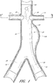
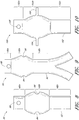
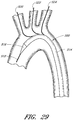
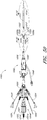
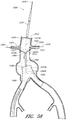
- FIG. 1 an example of an endoluminal prosthesis is shown deployed in a patient's aorta 10.
- An anuerysmic sac 10A is also shown.
- Figure 2 is a side view of the endoluminal prosthesis 20 illustrated in Figure 1 .
- the example of the endoluminal prosthesis 20 illustrated in Figures 1 and 2 can have a main graft body 22, a first fenestration 24, and a second fenestration 26.
- At least a portion of the graft material adjacent to the one or more fenestrations or openings can be free to translate in a circumferential or axial direction relative to the stent that the graft is supported by.
- particular portions such as the end portions of the graft material can be sutured or otherwise fastened to the stent, while a mid portion of the graft having one or more fenestrations therethrough can be unattached to the stent so that such mid portion can be free to translate relative to the stent and, hence, permit the adjustability of the fenestrations relative to the stent.
- the fenestrations can be adjusted to align with the ostium of the patient's branch vessels.
- the diameter of the main graft body 22 configured for placement in an approximately 26 mm vessel can be approximately 34 mm. Therefore, in some embodiments, the diameter of the main graft body 22 can be approximately 8 mm larger than the diameter of the target vessel. In some embodiments and examples, the diameter of the main graft body 22 can be between approximately 2 mm and approximately 14 mm, or between approximately 4 mm and approximately 12 mm, or between approximately 6 mm and approximately 10 mm larger than the diameter of the target vessel, or to or from any values within these ranges.
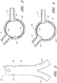
- Figure 3 is a cross-sectional view of the example of the endoluminal prosthesis 20 deployed in the patient's anatomy, taken through line 3-3 in Figure 1 , before the fenestrations 24, 26 have been aligned with the respective branch vessels, for example renal arteries 12, 14.
- the main graft body 22 (which can be oversized) has been deployed in the target vessel.
- folds 34 can form in the main graft body 22 about the circumference of the main graft body 22.
- the folds 34 can form in the main graft body 22 as a result of the fact that there can be excess or slack material in the main graft body 22 after the main graft body 22 has been deployed in the target vessel.
- the fenestration 24 can be drawn closer to the fenestration 26, thereby gathering slack material or folds 34 in a first portion 22a of the main graft body 22 and partially or fully removing the slack material or folds from a second portion 22b of the main graft body 22.
- a covered stent, a bare wire stent, or any other suitable stent or anchoring device can be deployed within the main graft to secure the graft in the desired location (not illustrated).
- a bare metal stent deployed within the main graft body 22 can compress the folds 34 that are formed in the main graft body 22, if any, against the wall of the vessel and secure the main graft body 22 and the fenestrations 24, 26 in the desired locations.
- a supra renal stent can be deployed at a distal or upper portion of the main graft body to secure the distal or upper portion of the main graft body in the desired location within the patient's vasculature, and one or more axial springs 40 can be anchored to the main graft body to provide axial or column strength to the main graft body.
- the springs 40 can have a helical shape, as illustrated, and can have any suitable size, length, pitch, or diameter. However, such helical shape is not required. In some embodiments and examples, the springs 40 can have any suitable shape, including a straight, flat, round, or non-round shape.
- the springs 40 can be formed from any suitable biocompatible material, such as without limitation stainless steel, Nitinol, or suitable metalic or polymeric materials.
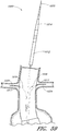
- Figure 5 is a partial section view of a patient's vasculature illustrating another example of an endoluminal prosthesis 20' deployed in the desired position within the patient's vasculature wherein the main graft body 22' can have a supra renal stent 38 deployed within the upper or distal end portion of the main graft body 22' and one or more axial springs 40 secured to the main graft body 22'.
- the springs 40 can be secured to the main graft body 22' using any suitable fasteners or method, such as without limitation, sutures or adhesive.
- any of the embodiments and exampless of the endoluminal prostheses disclosed herein can be formed such that one or more portions of the main graft body have an enlarged diameter, while one or more other portions of the main graft body can have a reduced diameter as compared to the enlarged diameter.
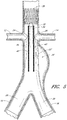
- the endoluminal prosthesis 60 can have a main graft body 62 and fenestrations 64, 66 formed therein.
- an additional fenestration 68 can be formed in the main graft body 62 to accommodate blood flow to the SMA or otherwise.
- a first or upper portion 62a of the main graft body 62 can have a first diameter while a second or lower portion 62b can have a second diameter.
- the first portion 62a can have a smaller diameter than the second portion 62b of the main graft body 62. Accordingly, to accommodate adjustability of the fenestrations 64, 66, the fenestrations 64, 66 can be formed in the second or enlarged portion 62b of the main graft body 62.
- the first portion 62a can have any diameter suitable for the size of the target vessel.
- the second portion 62b can have an enlarged diameter within any of the ranges described above with respect to the main graft body 22.
- the endoluminal prosthesis 60 can be configured for deployment in a 26 mm target vessel, wherein the first portion 62a can have an approximately 28 mm or any other suitable diameter, and the second portion 62b can have an approximately 34 mm or any other suitable enlarged diameter so as to allow for the adjustability of the fenestrations 64, 66.
- the diameter of the main graft body 62 in the second portion 62b can transition from the diameter of the first portion 62a to the diameter of the remainder of the second portion 62b.
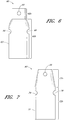
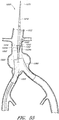
- Figure 7 is a side view of another example of an endoluminal prosthesis 70 having a main graft body 72 and fenestrations 74, 76 formed therein.
- an additional fenestration or cutout 78 can be formed in the main graft body 72 to accommodate blood flow to the SMA or otherwise.
- a first or upper portion 72a of the main graft body 72 can be tapered from a first to a second diameter, while a second or lower portion 72b can have a second diameter.
- the first portion 72a can have a smaller diameter than the second portion 72b of the main graft body 72. Accordingly, to accommodate adjustability of the fenestrations 74, 76, the fenestrations 74, 76 can be formed in the second or enlarged portion 72b of the main graft body 72.
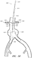
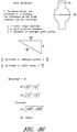
- Figure 8 is a side view of another example of an endoluminal prosthesis 80 having a main graft body 82 and fenestrations 84, 86 formed therein.
- an additional fenestration 88 can be formed in the main graft body 82 to accommodate blood flow to the SMA or otherwise.
- a first or upper portion 82a of the main graft body 82 can have a first diameter
- a second or middle portion 82b can have a second diameter
- a third or lower portion 82c can have a third diameter.
- the first portion 82a can have a smaller diameter than the second portion 82b of the main graft body 82.
- the third portion 82c can have a smaller diameter than the second portion 82b of the main graft body 82. In some embodiments and examples, the third portion 82c can have the same diameter as compared to the first portion 82a. Accordingly, to accommodate adjustability of the fenestrations 84, 86, the fenestrations 84, 86 can be formed in the second or enlarged portion 82b of the main graft body 82.
- the second portion 82b can have a generally curved surface, or can define a generally cylindrical surface that conically or curvedly tapers to the diameter of the first and third portions 82a, 82c.
- the first portion 82a can have any suitable first diameter for the size of the target vessel. Additionally, as mentioned, the second portion 82b can have an enlarged diameter within any of the ranges described above.
- the endoluminal prosthesis 80 can be configured for deployment in a 26 mm target vessel, wherein the first portion 82a can have an approximately 28 mm diameter, the second portion 82b can have an approximately 34 mm diameter so as to allow for the adjustability of the fenestrations 84, 86, and the third portion 82c can have an approximately 28 mm diameter.
- any of the endoluminal prostheses disclosed or described herein can be bifurcated or non-bifurcated, and can be formed from any suitable material, such as but not limited to ePTFE.
- any of the deployment procedures described herein or any other suitable deployment procedures currently known or later developed that are suitable for such endoluminal prostheses can be used to deploy any of the endoluminal prostheses described herein.
- any of the endoluminal prostheses can be secured to the target vessel wall using covered stents, bare metal stents, supra renal stents, springs, anchors, or any other suitable medical device or fasteners.
- the endoluminal prosthesis 90 can be a bifurcated prosthesis.
- the main graft body 92 can have three portions 92a, 92b, 92c of varying diameters.
- At least a portion of the graft material adjacent to the one or more fenestrations or openings can be free to translate in a circumferential or axial direction relative to the stent that the graft is supported by.
- particular portions of the graft material such as the end portions of the graft material, can be sutured or otherwise fastened to the stent, while a mid or enlarged portion of the graft having one or more fenestrations therethrough can be unattached to the stent so that such portion can be free to translate relative to the stent.
- This configuration can improve the adjustability of the graft material and, hence, the fenestrations, relative to the stent, permitting the fenestrations to be adjusted to align with the ostium of the patient's branch vessels.
- any of the embodiments and examples of the endoluminal prostheses disclosed herein can be formed with a branch graft adjacent to one or more of the openings or fenestrations formed in the main graft body.
- the endoluminal prosthesis 100 can have a main graft body 102 and branch grafts 104, 106 supported by the main graft body 102.
- an additional fenestration 108 can be formed in the main graft body 102 to accommodate blood flow to the SMA or otherwise.
- an additional branch graft (not illustrated) can be supported by the main graft body 102 to accommodate the blood flow to the SMA
- a first or upper portion 102a of the main graft body 102 can have a first diameter
- a second or middle portion 102b can have a second diameter
- a third or lower portion 102c can have a third diameter.
- the main graft body 102 can have any suitable shape, including any of the shapes disclosed elsewhere herein.
- the first portion 102a can have a smaller diameter than the second portion 102b of the main graft body 102.
- the third portion 102c can have a smaller diameter than the second portion 102b of the main graft body 102.
- the third portion 102c can have the same diameter as compared to the first portion 102a. Accordingly, to accommodate adjustability of the branch grafts 104, 106, the branch grafts 104, 106 can be supported by the second or enlarged portion 102b of the main graft body 102.
- the first portion 102a can have any suitable first diameter for the size of the target vessel. Additionally, as mentioned, the second portion 102b can have an enlarged diameter within any of the ranges described above.
- the endoluminal prosthesis 100 can be configured for deployment in a 26 mm target vessel, wherein the first portion 102a can have an approximately 28 mm diameter, the second portion 102b can have an approximately 34 mm diameter so as to allow for the adjustability of the fenestrations 104, 106, and the third portion 102c can have an approximately 28 mm diameter.
- the branch grafts 104, 106 can be integrally formed with the main graft body 12.
- the branch graft portions 104, 106 can be formed separately and later attached, adhered, sutured, or otherwise fastened or supported by the main graft body 102.
- the main graft body 102 can have fenestrations or openings in place of the branch grafts 104, 106.
- any of the embodiments and examples of the endoluminal prostheses disclosed herein can be formed with a branch graft adjacent to one or more of the openings or fenestrations formed in the main graft body.
- Figure 10 which is a side view of another embodiment of an endoluminal prosthesis 100
- an additional fenestration 108 can be formed in the main graft body 102 to accommodate blood flow to the SMA or otherwise.
- an additional branch graft (not illustrated) can be supported by the main graft body 102 to accommodate the blood flow to the SMA
- a first or upper portion 102a of the main graft body 102 can have a first diameter
- a second or middle portion 102b can have a second diameter
- a third or lower portion 102c can have a third diameter.
- the main graft body 102 can have any suitable shape, including any of the shapes disclosed elsewhere herein.
- the first portion 102a can have a smaller diameter than the second portion 102b of the main graft body 102.
- the third portion 102c can have a smaller diameter than the second portion 102b of the main graft body 102.
- the third portion 102c can have the same diameter as compared to the first portion 102a. Accordingly, to accommodate adjustability of the branch grafts 104, 106, the branch grafts 104, 106 can be supported by the second or enlarged portion 102b of the main graft body 102.
- the first portion 102a can have any suitable first diameter for the size of the target vessel. Additionally, as mentioned, the second portion 102b can have an enlarged diameter within any of the ranges described above.
- the endoluminal prosthesis 100 can be configured for deployment in a 26 mm target vessel, wherein the first portion 102a can have an approximately 28 mm diameter, the second portion 102b can have an approximately 34 mm diameter so as to allow for the adjustability of the fenestrations 104, 106, and the third portion 102c can have an approximately 28 mm diameter.
- the branch grafts 104, 106 can be integrally formed with the main graft body 12.
- the branch graft portions 104, 106 can be formed separately and later attached, adhered, sutured, or otherwise fastened or supported by the main graft body 102.
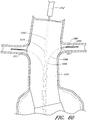
- the endoluminal prosthesis 110 can have a main graft body 112, fenestrations 114, 116 formed in the main graft body 112, and an opening or cutout 118 formed in the distal end portion of the main graft body 112 to accommodate blood flow to the SMA or otherwise.
- branch grafts can be positioned within the fenestrations 114, 116, or can be sewn, adhered, or otherwise attached to the main graft body 112 adjacent to the fenestrations 114, 116.
- the main graft body 112 can have three portions 112a, 112b, 112c of varying diameters.
- the diameter of the three portions 112a, 112b, 112c of the main graft body 112 can be approximately the same.
- the first portion 112a can have any diameter suitable for the size of the target vessel.
- the second portion 112b can have an enlarged diameter within any of the ranges described above with respect to the main graft body 22.
- the endoluminal prosthesis 110 can be configured for deployment in a 26 mm target vessel, wherein the first portion 112a can have an approximately 28 mm or any other suitable diameter, and the second portion 112b can have an approximately 34 mm or any other suitable enlarged diameter so as to allow for the adjustability of the fenestrations 114, 116.
- the diameter of the third portion 112c can be similar to the diameter of the first portion 112a, or can be any suitable diameter.
- the main graft body 112 be sized and configured so as to have excess length or material 120 in the graft material.
- the main graft body 112 can be sized and configured so as to have excess material 120 below the enlarged second portion 112b.
- the main graft body 112 can be configured so that the excess material 120 is positioned above the enlarged second portion 112b, or so that excess material 120 is positioned both above and below the enlarged second portion 112b to allow for greater axial and/or radial adjustability of the fenestrations 114, 116.
- the excess material positioned above and/or below the enlarged portion or, if no enlarged portion, above and/or below the fenestrated portion, can permit a greater amount of adjustability of the fenestrations or branch grafts.
- Any of the embodiments and examples of grafts disclosed herein can have excess material positioned above and/or below the enlarged or fenestrated portion of the graft, or at any suitable position on the graft to increase the adjustability of the fenestrations or branch grafts.
- the excess material 120 can be approximately 20% of the unstretched length of the main graft body 112. In some embodiments and examples, the excess material 120 can be from approximately 10% or less to approximately 30% or more of the unstretched length of the main graft body 112. For example, in some embodiments and examples, the total excess length of the graft can be approximately 2 cm. In some embodiments and examples, the total excess length of the graft can be between approximately 1 cm and approximately 3 cm such that a main graft body 112 having an unstretched length of approximately 10 cm can have from approximately 11 cm or less to approximately 13 cm or more of graft material positioned thereon.
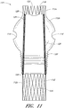
- the endoluminal prosthesis 110 can have a supra visceral stent or stent segment 122 deployed within the first or distal end portion 112a of the main graft body 112, a stent segment 124 deployed within the third or proximal end portion 112c of the main graft body 112, and one or more axial springs 126 extending between the supra renal stent segment 122 and the stent segment 124.
- the springs 126 can be substantially rigid so as to axially position the stent segment 122 at a fixed position relative to the stent segment 124.
- the springs 126 can be attached to the stent segments 124, 126 at connection points 128.
- the endoluminal prosthesis 110 can be configured such that the main graft body 112 is secured to the stent segments 122, 124 only at the end portions of the main graft body 112. In some embodiments and examples, the endoluminal prosthesis 110 can be configured such that the main graft body 112 is secured to the stent segments 122, 124 at the end portions of the main graft body 112 and also at one or more intermediate positions, such as at positions adjacent to one or more of the connection points 128.
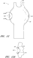
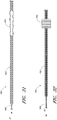
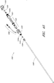
- Figure 12 is a side view of another example of an endoluminal prosthesis 140.
- Figure 12A is an enlarged side view of the embodiment of the endoluminal prosthesis 140 defined by curve 12A-12A in Figure 12 .
- any of the features of the endoluminal prosthesis 140 can be combined with any of the features of any other embodiment, example or combination of embodiments and/or examples of the endoluminal prostheses disclosed herein.
- endoluminal prosthesis 140 can have any of the features, components, or other details of any of the other embodiments and examples of the endoluminal prostheses disclosed herein.
- the endoluminal prosthesis 140 can have a main graft body 142, fenestrations 144, 146 formed in the main graft body 142, and an opening or cutout 148 formed in the distal end portion of the main graft body 142 to accommodate blood flow to the SMA or otherwise.
- branch grafts can be positioned within the fenestrations 144, 146, or can be sewn, adhered, or otherwise attached to the main graft body 112 adjacent to the fenestrations 144, 146.
- the diameter of the fenestrations 144, 146 or any other fenestrations disclosed herein can be from approximately 1 mm to approximately 10 mm or more, or from approximately 3 mm to approximately 8 mm, or from approximately 4 mm to approximately 6 mm.
- the fenestrations 144, 146 can be positioned at any desired or suitable axial or radial position in the main graft body 142 based on a patient's anatomy.
- the fenestration border 150 can be a generally cylindrically shaped tube of graft material such as PTFE, ePTFE, or any other suitable material that is formed around the fenestration.
- the tube of graft material can be slit longitudinally along the length thereof and positioned over the edge of the fenestrations 144, 146.
- the fenestration border 150 can be bonded, sutured, or otherwise attached to or supported by the main graft body 142 adjacent to the fenestrations 144, 146.
- the fenestration border 150 can be a ring of polyurethane or urethane that can be bonded, sutured, or otherwise attached to or supported by the main graft body 142 adjacent to the fenestrations 144, 146.
- the polyurethane or urethane can allow for radial expansion of the fenestration by a balloon expander or other suitable expander.
- the polyurethane or urethane rings (or rings made from any other suitable material) can be positioned between two or more sheets or layers of graft material (such as, but not limited to, ePTFE) having the polyurethane or urethane bonded thereto.
- the sheets or layers can be positioned relative to one another with the polyurethane or urethane surfaces facing each other so that the polyurethane or urethane is sandwiched between the sheets or layers of the graft material.
- a radiopaque material (that can be non-rigid or spring-like) can be embedded in or supported within the fenestration border 150.
- the radiopaque marker can be formed from platinum iridium, which can be in the form of a spring, or any other suitable metallic material known to the industry.
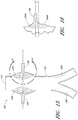
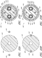
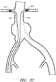
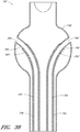
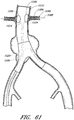
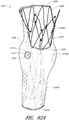
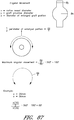
- Figure 13 is a side view of another example of an endoluminal prosthesis 170.
- Figure 14 is a top view of the example of the endoluminal prosthesis 170 shown in Figure 13 .
- the example of the endoluminal prosthesis 170 illustrated in Figures 13 and 14 can have a main graft body 172, a first fenestration 174, and a second fenestration 176.
- the main graft body 172 can be bifurcated, having a first bifurcated branch 178 and a second bifurcated branch 180 for placement in the ipsilateral and contralateral iliac arteries and a lumen 182 through the main graft body 172 in communication with the openings in the first and second bifurcated branches 178, 180.
- the endoluminal prosthesis 170 can have any of the components, features, dimensions, materials, or other details of any of the other embodiments and examples of endoluminal prostheses disclosed herein, or any other suitable features of endoluminal prostheses known in the field.
- the endoluminal prosthesis 170 can be formed from any suitable material, such as, but not limited to, ePTFE. In some embodiments and examples, the endoluminal prosthesis 170 can be formed from an expandable material. The endoluminal prosthesis 170 can be formed such that at least a portion of the main graft body 172 can be significantly larger than the target vessel into which the main graft body 172 is to be deployed. With reference to Figure 13 , the endoluminal prosthesis 170 can be bifurcated and can be deployed so as to span across an aneurysm in the abdominal aortic. In some embodiments and examples, at least a portion of the main graft body 172 can have a diameter that can be approximately 30% larger than the diameter of the target vessel.
- At least a portion of the main graft body 172 can have a diameter that can be from approximately 20% or less to approximately 50% or more, or from approximately 25% to approximately 40% larger than the target vessel, or to or from any values within these ranges.
- the main graft body 172 configured for placement in an approximately 28 mm vessel can have at least a portion thereof that has a diameter of approximately 34 mm. Therefore, in some embodiments and examples, the diameter of at least a portion of the main graft body 172 can be approximately 8 mm larger than the diameter of the target vessel. In some embodiments and examples, the diameter of at least a portion of the main graft body 172 can be between approximately 2 mm and approximately 14 mm, or between approximately 4 mm and approximately 12 mm, or between approximately 6 mm and approximately 10 mm larger than the diameter of the target vessel, or to or from any values within these ranges.
- the main graft body 172 can have a first portion 172a, a second or middle portion 172b, and a third or lower portion 172c.
- the first portion 172a can have a generally cylindrical shape defined by a first diameter.
- the second portion 172b can have a generally spherical shape defined by a second, enlarged diameter.
- the third portion 172c can have a generally cylindrical shape defined by a third diameter. The third diameter can be approximately the same as the first diameter, or can be larger or smaller than the first diameter.
- the second portion 172b can have approximately the same cross-sectional diameter as compared to the first portion 172a, the second portion 172b having corrugations 184 formed therein, as described below, to allow for the adjustability of the fenestrations 174, 176 or branch grafts (not illustrated).
- the oversized diameter of the main graft body 172 can provide excess or slack graft material in the main graft body 172 such that the fenestrations 174, 176 can each be moved in an axial or angular direction to align the fenestrations 174, 176 with the branch vessels arteries.
- branch grafts (not illustrated) can be integrally formed with the main graft body 172, or can be formed separately and later attached, adhered, sutured, or otherwise fastened or supported by the main graft body 172.
- two or more fenestrations 174, 176 can be formed in the main graft body 172 at any desired location.
- the two fenestrations 174, 176 can be formed at generally diametrically opposed locations.
- any number of fenestrations can be formed in the main graft body 172 at any desired locations.
- scallops or cutouts can be formed in the distal end portion or at any suitable location in the main graft body 172, the scallops or cutouts being configured to prevent obstruction of other arteries branching off of the main vessel into which the main graft body 172 is to be deployed.
- an additional fenestration can be formed in a distal portion of the main graft body 172 so as to align with a patient's SMA.
- the fenestrations 174, 176 can be formed in the second portion 172b of the main graft body 172.
- the surface of the second portion 172b of the main graft body 172 can have waves, undulations, folds, corrugations, or other similar features 184 (collectively referred to as corrugations) pre-formed therein.
- the corrugations 184 can be formed in an axial direction, as illustrated in Figures 13 and 14 , or can be formed in a lateral direction or at any other suitable angular orientation. Additionally, the corrugations 184 can have a linear shape, as illustrated, or can have a curved or any other suitable shape, such as is illustrated in Figures 15 and 16 .
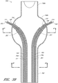
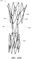
- Figure 15 is a side view of another example of an endoluminal prosthesis 190
- Figure 16 is an enlargement of a portion of the example of an endoluminal prosthesis 190 shown in Figure 15 , defined by curve 16-16, illustrating the adjustability of a branch graft.
- the example of the endoluminal prosthesis 190 illustrated therein can have a main graft body 192, a first branch graft 194, and a second branch graft 196.
- the main graft body 192 can be bifurcated, having a first bifurcated branch 198 and a second bifurcated branch 200 for placement in the ipsilateral and contralateral iliac arteries and a lumen 202 through the main graft body 192 in communication with the openings in the first and second bifurcated branches 198, 180.
- the endoluminal prosthesis 190 can have any of the components, features, dimensions, materials, or other details of any of the other embodiments and examples of endoluminal prostheses disclosed herein, or any other suitable features of endoluminal prostheses known in the field.
- the main graft body 192 can be formed without the branch grafts 194, 196 so that fenestrations are to be aligned with the branch vessels. Further, any suitable number of branch grafts or fenestrations can be formed on the main graft body 192.
- the corrugations 204 formed in the main graft body 192 can be curved.
- the corrugations 204 can be generally curved in shape and can be formed about the axial centerline of each of the branch grafts 194, 196.
- line L1 represents the axial centerline of each of the branch grafts 194, 196 when the branch grafts 194, 196 are in a relaxed state.
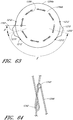
- the corrugations 204 can define a generally circular shape.
- the corrugations 204 can be configured to allow the branch grafts 194, 196 to move in an axial or angular direction to align the branch grafts 194, 196 with the branch vessels arteries.
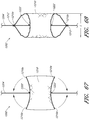
- Figure 16 is an enlargement of a portion of the endoluminal prosthesis 190 shown in Figure 15 , illustrating the adjustability of a branch graft 196.
- the branch graft 196 can be adjusted from the position defined by line L1 (which represents the axial centerline of the branch graft 196 in the relaxed state) to the position defined by line L2 (which represents the axial centerline of the branch graft 196 in the adjusted state).
- Lines L1 and L2 are meant to describe the adjustment of the branch grafts 194, 196 in any suitable axial or angular direction and are not meant to be limited by the example or examples provided herein. Further, lines L1 and L2 need not be parallel lines, since angular orientation of the branch grafts 194, 196 relative to the main graft body 192 can be adjustable also.
- the branch grafts 194, 196 can be approximately aligned so that the axial centerline of the branch graft 194 is approximately collinear with the axial centerline of the branch graft 196.
- the branch grafts 194, 196 can be positioned on the main graft body 192 so that the axial centerline of the branch graft 194 is not aligned or collinear with the axial centerline of the branch graft 196.
- one or more stents can be pre-positioned within the branch grafts before the endoluminal prosthesis has been deployed in the target location.
- the one or more stents can be balloon expandable, self-expandable, or other suitable stents that can be positioned within the branch grafts before the endoluminal prosthesis is loaded into a delivery catheter.
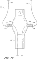
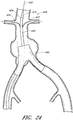
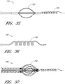
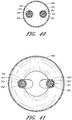
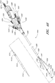
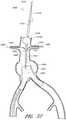
- the endoluminal prosthesis 300 can have a main graft body 302 and branch grafts 304, 306 supported by the main graft body 302.
- an additional fenestration can be formed in the main graft body 302 to accommodate blood flow to the SMA or otherwise.
- a branch graft (not illustrated) can be supported by the main graft body 302 to accommodate the blood flow to the SMA
- the endoluminal prosthesis 300 illustrated in Figure 17 can have any of the same features as compared to the example of the endoluminal prosthesis 100 illustrated in Figure 10 and described above or any of the embodiments and examples of the endoluminal prostheses disclosed herein.
- the branch grafts 304, 306 can be supported by the second or enlarged portion 302b of the main graft body 302.
- the branch grafts 304, 306 can be integrally formed with the main graft body 302.
- the branch graft portions 304, 306 can be formed separately and later attached, adhered, sutured, or otherwise fastened or supported by the main graft body 302.
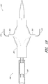
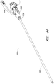
- first and second guidewires 310, 312 can be advanced through the branch grafts 304, 306, respectively.
- the guidewires 310, 312 can be hollow so that they can be passed or advanced over guidewires that are pre-wired in the patient's vasculature to guide the endoluminal prostheses 300 to the target location. Advancing the guidewires 310, 312 over the pre-wired guidewires can also facilitate the alignment of each of the branch grafts 304, 306 with each of the branch vessels in the patient's vasculature.
- the guidewires 310, 312 can be made from a plastic extrusion or metal braids.
- the hollow guidewires 310, 312 can be made from braided Nitinol wire.
- the outer diameter of the guidewires 310, 312 can be approximately 0.89 mm (0.035 in) and the lumen of the guidewire can be approximately 0.41 mm (0.016 in) to accommodate a second 0.36 mm (0.014 in) guidewire.
- the guidewires 310, 312 can be configured to pass over a 0.46 mm (0.018 in) or any other suitable guidewire.
- the guidewires 310, 312 can support balloons on the distal ends of the guidewires 310, 312.
- the balloons can be inflated in the branch vessel to deploy expandable stents within the branch grafts 304, 306.
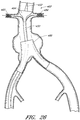
- stents 314, 316 can be positioned within each of the branch grafts 304, 306, respectively, before the endoluminal prosthesis 300 is loaded into the delivery catheter.
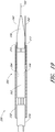
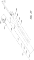
- each of the stents 314, 316 can be a bare metal stent or a covered stent (i.e., covered with a tubular shaped graft material).
- the stents 314, 316 can be self expanding or can be balloon expandable.
- each of the stents 314, 316 can be supported by an expansion balloon 318, 320, respectively, positioned within each of the branch grafts 304, 306.
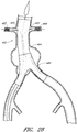
- each of the guidewires 310, 312 can be configured to allow for the inflation and expansion of the expansion balloons 318, 320.
- the guidewires 310, 312 can have a first lumen that can be advanced over a pre-wired guidewire and a second inflation lumen configured to communicate a positive pressure to each of the expansion balloons 318, 320.
- the endoluminal prostheses 300 can be loaded into a delivery catheter so that each of the guidewires 310, 312 protrudes out from the inside of an outer sleeve of the delivery catheter so that each of the guidewires 310, 312 can be advanced over the pre-wired guidewires positioned within the patient's vasculature.
- each of the stents 314, 316 can be expanded and hence deployed within each of the branch grafts 304, 306 after each of the branch grafts 304, 306 has been aligned and positioned within the respective branch vessels.
- each of the stents 314, 316 can be expanded and hence deployed within each of the branch grafts 304, 306 before the main graft body 302 has been secured in the main target vessel.
- the stents 314, 316 and the expansion balloons 318, 320 can be supported within the branch grafts 304, 306, respectively, so that the stents 314, 316 and the expansion balloons 318, 320 are axially secured to each of the branch grafts 304, 306.
- advancing the guidewires 310, 312 and, accordingly, the stents 314, 316 and the expansion balloons 318, 320, into the respective branch vessels after the endoluminal prosthesis 300 has been at least partially released from the deployment catheter can allow the branch grafts 304, 306 to be aligned with and advanced into the target branch vessels.
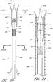
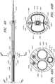
- covered or uncovered stents can be pre-positioned in the main graft body of a fenestrated endoluminal prosthesis so as to be partially advanced through each of the fenestrations before the endoluminal prosthesis is loaded into the delivery catheter.
- the stents can be secured to or otherwise configured to engage each of the fenestrations such that, as the stents are advanced along the pre-wired guidewires into the respective branch vessels, the fenestrations can be aligned with the respective branch vessels.
- the stents can have flanged portions or be partially expanded so as to engage the fenestrations such that advancing the stents into the respective branch vessels can align the fenestrations with the respective branch vessels.
- the guidewires themselves can be configured to engage each of the fenestrations such that, as the deployment guidewires are advanced along the pre-wired guidewires into the respective branch vessels, the fenestrations can be aligned with the respective branch vessels without the use of stents for alignment.
- one or more stents can be advanced through the patient's vasculature and into the branch grafts 304, 306 after the endoluminal prostheses 300 has been positioned within the target vessel in the patient's vasculature.
- one or more stents can be advanced through the patient's vasculature into the branch grafts 304, 306 after the branch grafts 304, 306 have been positioned within the target branch vessels and after the main graft body 302 has been secured within the main target vessel.
- 12/496,446 , 12/390,346 , and 12/101,863 can be used, with or without modification, to deploy any of grafts, stents, or other apparatuses disclosed herein, or in combination with any of the components or features of the deployment systems disclosed herein.
- Figure 18 is a side view of the endoluminal prosthesis 300 with guidewires 310, 312 advanced through each of the branch grafts 304, 306, showing the endoluminal prostheses 300 being loaded within a delivery catheter 330.
- the outer sheath 332 illustrated in Figure 18 is sectioned for clarity.
- the collapsed endoluminal prosthesis 300 can be supported within the outer sheath 332 of the delivery catheter 330 in the space between the catheter shaft 334 and the catheter tip 336.
- the hollow guidewires 310, 312 can slide through openings or lumens in the catheter shaft 86.
- the hollow guidewires 310, 312 can be fixed to the catheter shaft 334.
- Figure 19 is a side view of the endoluminal prostheses 300 with guidewires 310, 312 advanced through each of the branch grafts 304, 306, showing the endoluminal prostheses 300 fully loaded within a delivery catheter 330 and being advanced along guidewires pre-wired in the patient's vasculature.
- the outer sheath 332 illustrated in Figure 19 is sectioned for clarity.
- the hollow guidewires 310, 312 can be advanced through the branch grafts 304, 306, respectively, of the endoluminal prosthesis 300.
- the endoluminal prosthesis 300 can then be compressed and loaded within the delivery catheter 330, as is illustrated in Figure 19 .
- the endoluminal prosthesis 300 can be retained in the delivery catheter 330 by the outer sheath 332. Retraction of the outer sheath 332 can deploy the endoluminal prosthesis 300. With the outer sheath 332 retracted, the endoluminal prosthesis 300 can expand either by self-expansion, balloon expansion, or by any other suitable method or mechanism.
- the hollow guidewires 310, 312 can pass through the outer sheath 332 from the proximal end of the delivery catheter 330 (i.e., the end of the delivery catheter 330 located outside of the patient) to the distal end of the delivery catheter 330.
- Each of the hollow guidewires 310, 312 can be configured to receive or allow the insertion of a 0.36 MM (0.014 in) guidewire, a 0.46 MM (0.018 in) guidewire, a 0.89 MM (0.035 in) guidewire, or any diameter guidewire therethrough deemed suitable for the design.
- the hollow guidewires 310, 312 can pass over guidewires 340, 342 that can be pre-wired in the target vessels.
- the catheter 330 can have at least three lumens through at least a portion of the catheter 330.
- Each of the three lumens can be configured to receive a guidewire. Having three lumens through at least a portion of the catheter 330 can prevent twisting of the guidewires so as to ensure proper deployment of the endoluminal prostheses 300 or any other endoluminal prostheses disclosed herein.
- the catheter 330 can be configured to receive the pre-wired guidewire 344 through a lumen formed in the approximate center of the catheter. The lumen can pass through the catheter tip 336 and the catheter shaft 334.
- the guidewires 340, 342 can each be pre-wired through the patient's vasculature to pass into each of the target branch vessels branching from the target main vessel.
- the guidewire 344 can be passed through the target main vessel.
- each of the stents 304, 306 can be expanded in the branch vessels to secure the branch grafts 304, 306 in the branch vessels.
- a stent or other suitable device can be deployed within the main graft body 302 to secure the main graft body 302 within the main vessel.
- one or more of the pre-wired guidewires 340, 342 described above can be configured to be insertable into a branch vessel and to be biased such that an end portion of the guidewire 340, 342 remains in the branch vessel.
- Biasing the end portion of the guidewire 340, 342 to remain in the branch vessel can thus improve any of the deployment procedures described herein. Additional details regarding such guidewires is set forth below.
- Figure 20 is a side view of another embodiment of a delivery catheter 400 that can be used to deploy at least some of the embodiments and examples of the endoluminal prostheses disclosed herein, showing an example of an endoluminal prosthesis 402 being loaded within a delivery catheter 400.
- Figure 21 is an enlarged partial section view of a portion of the example of a delivery catheter 400 illustrated in Figure 20 , showing the endoluminal prostheses 402 loaded within a delivery catheter 400.
- the endoluminal prosthesis 402 can be similar to the endoluminal prosthesis 80 described above, can be a bifurcated endoluminal prosthesis such as endoluminal prosthesis 90 described above, or can have any of the features, components, or other details of any of the other endoluminal prostheses disclosed herein.
- the main graft body 404 can be configured to accommodate positional adjustability of the fenestrations 406, 408.
- fenestrations 406, 408 can be formed within an enlarged portion of the main graft body 404.
- the endoluminal prosthesis 302 can have a main graft body 404 having fenestrations 406, 408 formed therein, and one or more stent segments 410, 412 deployed within the main graft body 404.
- the stents 410, 412 can be bare metal, covered, self-expandable, balloon expandable, or any other suitable stents either disclosed herein or otherwise known in the art or later developed.
- first and second guidewire sheaths 420, 422 can be advanced through the fenestrations 406, 408, respectively, before the endoluminal prosthesis 402 is loaded into a delivery catheter 400 or otherwise such that the first and second guidewire sheaths 420, 422 are advanced through the fenestrations 406, 408, respectively, when the endoluminal prostheses 402 is in the loaded state in the delivery catheter 400.
- the guidewire sheaths 420, 422 can be hollow so that they can be passed or advanced over pre-positioned guidewires that are pre-wired in the patient's vasculature to guide the endoluminal prostheses 402 to the target location. Advancing the guidewire sheaths 420, 422 over the pre-wired guidewires can also facilitate the alignment of each of the fenestrations 406, 408 with each of the branch vessels in the patient's vasculature.
- each of the guidewire sheaths 420, 422 can be made from the same material and have the same features, sizes, or other details of any other guidewire disclosed herein, including without limitation guidewires 310, 312 described above. Additionally, as with guidewires 310, 312, in some embodiments and examples, the guidewire sheaths 420, 422 can support balloons on the distal ends of the guidewire sheaths 420, 422. The balloons can be inflated in the branch vessel to deploy expandable stents within or adjacent to the fenestrations 406, 408.
- flared, flareable, bare metal, covered, self-expandable, balloon expandable, or any other suitable stents disclosed herein, known in the field, or later developed can be positioned within each of the fenestrations 406, 408, respectively, before the endoluminal prosthesis 402 is loaded into the delivery catheter 400.
- the stents can be deployed following any suitable procedure, including without limitation the procedure described above with respect to the stents 314, 316.
- the branch stents (not illustrated) can be secured to or otherwise configured to engage each of the fenestrations 406, 408 such that, as the stents are advanced along the pre-wired guidewires into the respective branch vessels, the fenestrations 406, 408 can be aligned with the respective branch vessels.
- the stents can have flanged or flared portions or be partially expanded so as to engage the fenestrations 406, 408 such that advancing the stents into the respective branch vessels can align the fenestrations 406, 408 with the respective branch vessels.
- the guidewires themselves can be configured to engage each of the fenestrations 406, 408 such that, as the deployment guidewire sheaths 420, 422 are advanced along the pre-wired guidewires into the respective branch vessels, the fenestrations 406, 408 can be aligned with the respective branch vessels without the use of stents for alignment.
- one or more stents can be advanced through the patient's vasculature and into the fenestrations 406, 408 after the endoluminal prostheses 402 has been positioned within the target vessel in the patient's vasculature.
- one or more stents can be advanced through the patient's vasculature into the fenestrations 406, 408 after the main graft body 404 has been positioned within the main target vessel or after the fenestrations 406, 408 have been positioned adjacent to the target branch vessels.
- the delivery catheter 400 can have an outer sheath 430, a distal tip 432 having a lumen or opening 434 therethrough, and a central tube 436 that can secure the distal tip 432 to the delivery catheter 400.
- the opening 434 in the distal tip 432 can extend through the central tube 436 so that the delivery catheter 400 can be advanced over a pre-positioned guidewire.
- the outer sheath 430 can be axially moveable relative to the central tube 436 and the distal tip 432, so that the endoluminal prosthesis 402 can be exposed and deployed from the delivery catheter 400 by retracting the outer sheath 430 relative to the central tube 436 and the distal tip 432.
- the distal tip 432 can be made from a soft material and/or otherwise be configured to be atraumatic to the patient's vasculature so as to minimize injury to the patient's vasculature during advancement of the delivery catheter 400 through the patient's vasculature.
- the distal tip 432 can have a substantially circular cross-section along the length thereof, as illustrated in Figure 22A , which is a section view of an embodiment of a distal tip 432, taken through line 22A-22A in Figure 20 . As illustrated, the distal tip 432 can be tapered along a portion of the length thereof.
- the distal tip 432 can have a cross-section that is generally circular, as illustrated in Figure 22A .
- the distal tip 432' can have a non-circular cross-section.
- Figure 22B is a section view of another embodiment of a distal tip 432' that can be used with the example of the delivery catheter 400 that is illustrated in Figure 20 , taken through line 22B-22B in Figure 20 .
- the distal tip 432' can have one or more channels 438 formed along a portion of the length of the distal tip 432'.
- the one or more channels 438 (two being shown) can each be configured to receive a guidewire sheath 420, 422 therein.
- the two channels 438 can be configured to releasably receive each of the guidewire sheaths 420, 422 therein so as to reduce the cross-sectional profile of the delivery catheter 400 and to permit the outer sheath 430 to be advanced over the distal tip 432 with the guidewires positioned adjacent to the distal tip 432 and advancing beyond the distal tip 432 without obstruction from the guidewire sheaths 420, 422.
- the channels 438 can be configured so that the outer sheath 430 can be advanced over and fit closely around the distal tip 432.
- Figure 23A is a section view of the example of the delivery catheter 400 shown in Figure 20 , taken through line 23A-23A in Figure 20 .
- Figure 23B is a section view of the example of the delivery catheter 400 shown in Figure 20 , taken through line 23B-23B in Figure 20 .
- Figures 23A and 23B represent different examples of the delivery catheter 400.
- some embodiments and examples of the delivery catheter 400 can have an outer sheath 430 that can be advanced through an introducer sheath 444 and an inner core 446 that can be axially advanced relative to the outer sheath 430.
- the delivery catheter 400 can be configured so that the inner core 446 can be rotated relative to the outer sheath 430, or can be configured so that the inner core 446 can be rotationally linked to the outer sheath 430. Additionally, the inner core 446 can be configured to axially support the central tube 436 and, hence, the distal tip 432 so that, as the inner core 446 is advanced relative to the outer sheath 430, the central tube 436 and the distal tip 432 can be simultaneously advanced relative to the outer sheath 430.
- a lumen 450 can be formed axially through at least a portion of the inner core 446, the lumen 450 being configured to slideably receive a guidewire 452 therein.
- the lumen 450 can be in communication with the opening 434 that can be formed through the distal tip 432 and the central tube 436 such that the opening 434 and the lumen 450 can slidingly receive a pre-positioned guidewire as the delivery catheter 400 is advanced over the guidewire.
- a lumen 454 can be formed through at least a portion of the inner core 446 as illustrated in Figure 23A , the lumen 454 being configured to slideably receive a guidewire, release wire, or other wire 456 therein.
- the endoluminal prosthesis 402 can be similar to or have any of the features of the endoluminal prostheses disclosed in U.S. Patent Application No. 12/101,863 ( US20090259298), filed on April 11, 2008 (entitled “BIFURCATED GRAFT DEPLOYMENT SYSTEMS AND METHODS").
- the release wire 456 can be or can be connected to the sheath release wire 166 used to deploy the main branch sheath 186 in U.S. Patent Application No. 12/101,863 ( US20090259298 ).
- a lumen 460 having one or more lobes can be formed axially through at least a portion of the inner core 446.
- the lumen 460 can be configured to receive one or more guidewires or guidewire sheaths therein.
- the lumen 460 can be configured to receive two guidewire sheaths therein, such as without limitation guidewire sheaths 420, 422.
- the guidewire sheaths 420, 422 each can be configured to receive a guidewire catheter therein, such as without limitation guidewire catheters 464, 466, respectively, having guidewires 468, 470 therein.
- the guidewire sheaths 420, 422 can each be sized and configured to axially receive a renal, covered or bare metal stent therein so that a renal stent can be advanced through the guidewire sheaths 420, 422 and deployed in the renal branch arteries as described herein.
- the renal stents (not illustrated) can be advanced over the guidewire catheters 464, 466 within the guidewire sheaths 420, 422.
- the hollow guidewire sheaths 420, 422 can slide within the lumen 460.
- the hollow guidewire sheaths 420, 422 can be fixed to the inner core 446.
- the guidewire catheters 464, 466 can each be configured to receive a pre-positioned guidewire therein, so that the guidewire catheters 464, 466 can be advanced over pre-positioned guidewires routed into the renal arteries as the delivery catheter 400 is advanced over the pre-positioned guidewire 452.
- the delivery catheter 400 can have an outer sheath 430 that can be advanced through an introducer sheath 444 and an inner core 446' that can be axially advanced relative to the outer sheath 430.
- the delivery catheter 400 can be configured so that the inner core 446' can be rotated relative to the outer sheath 430, or can be configured so that the inner core 446' can be rotationally linked to the outer sheath 430.
- the inner core 446' can be configured to axially support the central tube 436 and, hence, the distal tip 432 so that, as the inner core 446' is advanced relative to the outer sheath 430, the central tube 436 and the distal tip 432 can be simultaneously advanced relative to the outer sheath 430.
- a lumen 450 can be formed axially through at least a portion of the inner core 446', the lumen 450 being configured to slideably receive a guidewire 452 therein.
- the lumen 450 can be in communication with the opening 434 that can be formed through the distal tip 432 and the central tube 436 such that the opening 434 and the lumen 450 can slidingly receive a pre-positioned guidewire as the delivery catheter 400 is advanced over the guidewire.
- a lumen 454 can be formed through at least a portion of the inner core 446' as illustrated in Figure 23B , the lumen 454 being configured to slideably receive a guidewire, release wire, or other wire 456 therein.
- one or more channels 460' can be formed axially on at least a portion of the inner core 446'.
- the channels 460' can each be configured to receive one or more guidewires or guidewire sheaths therein.
- the channels 460' can be configured to receive two guidewire sheaths therein, such as without limitation guidewire sheaths 420, 422, configured as described above.
- the guidewire catheters 464, 466 can each be configured to receive a pre-positioned guidewire therein, so that the guidewire catheters 464, 466 can be advanced over pre-positioned guidewires routed into the renal arteries as the delivery catheter 400 is advanced over the pre-positioned guidewire 452.
- Figure 24 is a side view of an exmaple of a delivery catheter, such as without limitation delivery catheter 400 described above, showing a delivery catheter 400 being advanced distally past a bifurcated prosthesis 480 and showing guidewire sheaths 420, 422 being advanced into the renal arteries.
- the delivery catheter 400 can then be advanced through the main body of the bifurcated prosthesis 480 into the abdominal aorta and renal artery region.
- the guidewire sheaths 420, 422 can be advanced along pre-positioned guidewires into the renal arteries.
- the outer sheath 430 can be partially retracted so that the guidewire sheaths 420, 422 can be advanced into the renal arteries as the distal tip 432 of the delivery catheter 400 is advanced past the renal arteries along guidewire 452. Thereafter, the pre-placement guidewires (if any) positioned within the guidewire sheaths 420, 422 and already advanced into the renal arteries can be removed.
- biased guidewires 482, 484 can be advanced through the guidewire sheaths 420, 422 and into the renal arteries.
- the coiled distal end portions 482a, 484a of each of the biased guidewires 482, 484 can be configured to be insertable into a branch vessel and can be biased to remain in the branch vessel.
- Figure 26 is a side view of the example of the delivery catheter 400 shown in Figure 24 , showing the embodiment of the endoluminal prosthesis 402 being deployed within the target vessel region.
- the endoluminal prosthesis 402 can be a fenestrated cuff.
- the endoluminal prosthesis 402 can be deployed by any suitable method, such as without limitation removing a restraining sheath or by any of the methods disclosed in U.S. Patent Application No. 12/390,346 or U.S. Patent Application No. 12/101,863 ( US20090216315 or US20090259298 ).
- the endoluminal prosthesis 402 can be deployed by removing a perforated sheath using a sheath release wire threaded through perforations in the sheath, such as is set forth in some embodiments of U.S. Patent Application No. 12/101,863 ( US20090259298 ).
- the proximal end portion of the endoluminal prosthesis 402 can be deployed by distally advancing a sheath or other restraint so as to deploy the proximal end of the endoluminal prosthesis 402 (i.e., the end of the endoluminal prosthesis 402 that is furthest advanced into the vasculature or closest to the heart).
- the proximal end of the endoluminal prosthesis 402 can be deployed proximal to the desired visceral vessel (such as, without limitation, the SMA) and then axially retracted until the proximal portion of the endoluminal prosthesis 402 is positioned just below the target visceral vessel (e.g., without limitation, the SMA).
- the adjustable fenestrations 406, 408 can then be adjusted to be positioned adjacent to the respective renal arteries.
- the distal portion of the endoluminal prosthesis 402 i.e., the portion of the endoluminal prosthesis 402 furthest away from the heart
- Figure 27 is a side view of the example of the delivery catheter 400 shown in Figure 24 , showing the endoluminal prosthesis 402 after the distal portion of the endoluminal prosthesis 402 has been deployed within the bifurcated prosthesis 480.
- the inner core 446, distal tip 432, and central tube 436 can be axially retracted through the outer sheath 430 and removed from the target vessel region, leaving the guidewire sheaths 420, 422 positioned within the patient's renal arteries.
- the delivery catheter 400 illustrated in Figure 23B can be configured such that the inner core 446, distal tip 432, and central tube 436 can be axially retracted through the outer sheath 430 while leaving the guidewire sheaths 420, 422 positioned within the renal arteries.
- any suitable renal stents can be advanced through the guidewire sheaths 420, 422 and deployed within the renal arteries over the biased guidewires 482, 484 or other guidewires in the renal arteries.
- renal stents (such as without limitation stents 314, 316) can be advanced through the guidewire sheaths 420, 422 and deployed within the renal arteries over the biased guidewires 482, 484 or any other guidewires without removing the inner core 446, distal tip 432, and central tube 436.
- Figure 29 is a side view of another embodiment of a delivery catheter 500 showing a delivery catheter 500 being advanced distally past branch arteries in the thoracic aorta region of a patient's vasculature.
- Figure 30 is a side view of an endoluminal prosthesis 502 that can be deployed using the example of the delivery catheter 500 shown in Figure 29 .
- the endoluminal prosthesis 502 can have a main graft body 504 having multiple fenestrations 506, 508, 510 formed therein.
- the delivery catheter 500 can have an outer sheath 514 and a distal tip 516 configured to be advanced over a guidewire 518, as with the other embodiments and examples of the delivery catheters disclosed herein.
- the endoluminal prosthesis 502 and delivery catheter 500 can have any of the components, features, or other details of any of the other endoluminal prostheses or delivery catheters disclosed herein.
- the endoluminal prosthesis 502 can have stents or stent segments deployed within the main graft body 504, springs, or other suitable structures deployed or supported within the main graft body 504.
- the main graft body 504 can have an enlarged diameter along at least a portion of the main graft body 504 and/or an additional graft material or length along at least a portion of the main graft body 504 to improve the adjustability of the fenestrations 506, 508, 510.
- the delivery catheter 500 and the endoluminal prosthesis 502 can be configured such that a guidewire sheath (such as without limitation guidewire sheaths 420) can be pre-positioned within the delivery catheter 500 and the endoluminal prosthesis 502, the guidewire sheaths (not illustrated in Figures 29 , 30 ) advancing through each of the fenestrations 506, 508, 510.
- the distal tip 516 of the delivery catheter can be configured to have channels formed therein configured to receive the guidewire sheaths, similar to the distal tip 432' disclosed herein.
- the branch arteries can be pre-wired with guidewires 520, 522, 524 (which can be biased guidewires), similar to any of the pre-wiring techniques for the renal arteries disclosed herein, so that the delivery catheter 500 and the endoluminal prosthesis 502 having guidewire sheaths positioned therein can be advanced over the guidewires 520, 522, 524 to approximately align the fenestrations 506, 508, 510 as the endoluminal prosthesis 502 is being advanced into the target vessel region.
- the guidewire sheaths can be advanced into the branch arteries as the endoluminal prosthesis 502 is being deployed, similar to the deployment of the aortic grafts disclosed herein. Thereafter, any suitable branch stents (such as without limitation stents 314, 316) can be advanced through the guidewire sheaths (not illustrated) and deployed within the branch arteries over the guidewires 520, 522, 524.
- Figure 31 is a section view of an embodiment of a guidewire 700, showing the guidewire 700 in the open or collapsed configuration.
- Figure 32 is a section view of the embodiment of the guidewire 700 shown in Figure 31 , showing the guidewire 700 in the closed or expanded configuration.
- the guidewire 700 can be used in place of either of the guidewires 340, 342 shown in Figure 19 and described above.
- Any of the guidewires disclosed herein can comprise a shape memory material, such as without limitation Nitinol.
- the guidewire 700 can have an outer guidewire sheath 702 having an expandable portion 704. Additionally, the guidewire 700 can have an inner guidewire core 706 slidably received within a lumen formed within the outer guidewire sheath 702. In some embodiments and examples, the outer guidewire sheath 702 can be sized and configured such that the guidewires 310, 312 described above or any other guidewires or lumens can be advanced over the outside of the outer guidewire sheath 702, as described above.
- the expandable portion 704 can be configured such that, when the expandable portion 704 is axially collapsed, the diameter of the expandable portion 704 can increase and be configured such that, when the expandable portion 704 is axially extended, the diameter of the expandable portion 704 can decrease.
- the expandable portion 704 can be axially extended, thus reducing the diameter of the expandable portion 704.
- the collapsible portion can be axially compressed, thus increasing the diameter of the expandable portion 704.
- the expandable portion 704 can have a bellows type, undulating, or corrugated outer surface.
- the guidewire 700 can be advanced through the patient's vasculature to the target branch vessel while the guidewire 700 is in the collapsed configuration (i.e., the configuration shown in Figure 31 ).
- the inner guidewire core 706 can then be retracted relative to the outer guidewire sheath 702 (i.e., retracted in direction A2 relative to the outer guidewire sheath 702) so that the diameter of the expandable portion 704 can be increased and expand radially against the inner surface of the branch vessel wall.
- the expandable portion 704 can secure the distal end portion of the guidewire 700 in the desired branch vessel.
- the expandable portion 704 can be formed from a soft, atraumatic material to minimize the risk of any injury to the vessel wall.
- Figures 33 and 34 each illustrate a pair of guidewires 700 positioned within the patient's vasculature such that the distal end portions of the guidewires 700 can be secured at least partially within the patient's branch vessels.
- the guidewires 700 can be positioned within the patient's vasculature such that a portion of the expandable portion 704 protrudes into the lumen of the main vessel, which a portion of the expandable portion 704 protrudes into the branch vessel.
- the distal end portion of the guidewires 700 have been advanced further as compared to the guidewires 700 shown in Figure 33 , to allow additional space for the deployment of branch grafts within the branch vessels.
- the expandable portion 704 can be formed from metal, plastic, or any other suitable material, and can have an expandable bellows configuration or can be formed from one or more braids of wire. Additionally, in some embodiments and examples, the expandable portion 704 can be used to align the fenestrations or branch grafts with the branch vessels.
- any of the deployment catheters described above can then be advanced over the guidewires 700.
- the guidewire core 706 can then be retracted relative to the outer sheath 702 of the guidewires 700 so that the guidewires 700 can be removed from the patient's vasculature.
- other securing mechanisms can be attached to the distal end portion of the guidewire, such as, without limitation, hooks, barbs, or other similar features, to removably secure one or more of the guidewires 700 within the vessel.
- one of more of the guidewires disclosed herein can have a coiled distal end portion.
- the coiled distal end portion can be configured to be insertable into a branch vessel and can be biased to remain in the branch vessel.
- the size or diameter of the coils can be greater than the inside diameter of the branch vessel so as to bias the coiled portion to remain within the branch vessel when the proximal end of the guidewire is retracted.
- proximal retraction of the guidewire can cause a proximal end of the coil to unravel, allowing a portion of the coiled portion of the guidewire to be unraveled and retracted while the remaining portion of the coiled portion can remain within the branch vessel.
- This configuration can inhibit the distal end portion of the guidewire from being inadvertently removed from the branch vessel.
- the guidewire can be retracted until the entire coiled portion is unraveled and retracted.
- the inner guidewire core 706 of the guidewire 700 can be configured such that, when the distal end of the inner guidewire core 706 is advanced beyond the distal end of the outer guidewire sheath 702, the distal end of the inner guidewire core 706 forms coils that expand against the inner vessel wall and secure the guidewire 700 to the branch vessel.
- Figure 35 is a side view of another example of an expandable guidewire 720, showing the guidewire 720 in an expanded configuration.
- the guidewire 720 can have expansion struts 722 that can expand when deployed in the renal or other branch arteries.
- the guidewire 720 can be formed from a tube of Nitinol that can be perforated or cut so as to form a plurality of axial members or struts 722, and heat set so that the expansion struts 722 form a size that is larger than the desired vessel diameter.
- the guidewire can have four or less, or six, or eight or more struts 722.
- the guidewire 720 can be advanced through a tubular guidewire sheath that terminates in the desired branch vessel location. As the expansion struts 722 exit the distal end of the tubular guidewire sheath, the expansion struts 722 can self-expand against the walls of the target vessel so as to bias the guidewire 720 in the desired location.
- a two-way guidewire i.e., one having sufficient compressive and tensile strength
- the guidewire 722 can have a coiled end portion 724 to be more atraumatic.
- Figure 36 is a side view of another example of a guidewire 730, showing the guidewire 730 in an expanded configuration.
- the guidewire 730 can have a coiled expansion portion 732 that can expand when deployed in the renal or other branch arteries.
- the guidewire 730 can be formed from a tube of Nitinol that can be formed so as to define a coiled expansion portion, and heat set so that the coiled expansion portion 732 defines a diameter that is larger than the desired vessel diameter.
- the force from the coiled expansion portion 732 expanding against the vessel wall can provide a frictional force that inhibits the guidewire from being inadvertently removed from the target branch vessel.
- the coiled expansion portion 732 can have two or more, or four or more coils.
- the guidewire 730 can be advanced through a tubular guidewire sheath that terminates in the desired branch vessel location. As the coiled expansion portion 732 exits the distal end of the tubular guidewire sheath, the coiled expansion portion 732 can self-expand against the walls of the target vessel so as to bias the guidewire 730 in the desired location.
- a two-way guidewire i.e., one having sufficient compressive and tensile strength
- Figure 37 is a section view of another example of a guidewire 740, showing the guidewire 740 in an expanded configuration.
- the guidewire 740 can have a braided or wire expansion portion 742 that can expand when deployed in the renal or other branch arteries.
- the guidewire 740 can be formed from a tube of Nitinol that can be formed so as to define a coiled expansion portion, and heat set so that the braided or wire expansion portion 742 defines a diameter that is larger than the desired vessel diameter.
- the expansion portion 742 can be formed from between approximately five and ten or more wires each having a diameter between approximately 0.076 mm (0.003 in) or less and approximately 0.13 mm (0.005 in) or more.
- the expansion portion 742 can be formed from between approximately three and twelve or more wires.
- the force from the expansion portion 742 expanding against the vessel wall can provide a frictional force that inhibits the guidewire from being inadvertently removed from the target branch vessel.
- the guidewire 740 can be advanced through a tubular guidewire sheath that terminates in the desired branch vessel location. As the expansion portion 742 exits the distal end of the tubular guidewire sheath, the expansion portion 742 can self-expand against the walls of the target vessel so as to bias the guidewire 740 in the desired location.
- a two-way guidewire i.e., one having sufficient compressive and tensile strength
- Figure 38 is a side view of another example of an endoluminal prosthesis 745, showing the branch grafts 750 in an inverted position inside the main body 748 of the prosthesis 745.
- Figure 39 is a side view of the example of the prosthesis 745 shown in Figure 38 , showing the branch grafts 750 in an inverted position inside the main body 748 of the prosthesis 745 and showing an example of an angiographic catheter 751 being advanced through each of the inverted branch grafts 750 and the fenestrations 749.
- Some embodiments and examples of the angiographic catheter 751 can be configured such that an end portion thereof is biased to have a curved disposition. In some embodiments and examples, this can be accomplished by shortening the length of the wall of one side of the end portion of the angiographic catheter 751 as compared to the length of the wall of the other side of the angiographic catheter 751.
- Some embodiments and examples of the endoluminal prosthesis 745 can have a main graft body 748 having fenestrations or openings 749 therein and branch grafts 750 supported by the main graft body 748. Though not required, an additional fenestration can be formed in a first portion 748a of the main graft body 748 to accommodate blood flow to the SMA or otherwise. Alternatively, a branch graft (not illustrated) can be supported by the main graft body 748 to accommodate the blood flow to the SMA.
- the endoluminal prosthesis 745 illustrated in Figure 38 can have any of the same features, components, or other details as compared to any of the embodiments and examples of the endoluminal prostheses disclosed herein, including without limitation the example of the endoluminal prosthesis 100 illustrated in Figure 10 and described above.
- the branch grafts 750 can be supported by the second or enlarged portion 748b of the main graft body 748.
- the branch grafts 750 can be integrally formed with the main graft body 748.
- the branch graft portions 750 can be formed separately and later attached, adhered, sutured, or otherwise fastened or supported by the main graft body 748.
- angiographic catheters 751 or hollow guidewires can be advanced through the branch grafts 750 and fenestrations 749.
- the angiographic catheters 751 can define a lumen therethrough so that they can be passed or advanced over guidewires 752 that are pre-wired in the patient's vasculature to guide the endoluminal prostheses 745 to the target location. Advancing the angiographic catheters 751 over the pre-wired guidewires 752 can also facilitate the alignment of each of the branch grafts 750 with each of the branch vessels in the patient's vasculature.
- the branch grafts 750 can be inverted and positioned within the main body 748 of the prosthesis 745 during the initial steps of deployment of the prosthesis 745.
- the prosthesis 745 may be easier to advance to and deploy at the target vessel location when the branch grafts 750 are inverted and positioned within the main body 748 of the prosthesis 745.
- the prosthesis may be configured such that the branch grafts 750 can be advanced through the fenestrations 749 in the main body 748 of the prosthesis 745 and into the desired branch vessels after the main body 748 of the prosthesis 745 has been positioned in the target vessel location.
- one or more stents 757 can be deployed or expanded within the branch grafts 750 after the branch grafts have been advanced into the branch vessels.
- the stents 757, or any other stents disclosed herein, can be balloon expandable, self-expandable, flared, flareable, or be of any other suitable configuration or material, and can be carried or supported within a guidewire catheter sheath 754.
- the prosthesis 745 can be configured such that the stents 757 are affixed to an end portion of the branch grafts 750 such that the branch grafts 750 can be inverted and advanced through the fenestrations 749 formed in the main graft body 748 and into the branch vessels by advancing the stents 757 distally through the guidewire catheter sheath 754.
- the stents 757 can be advanced distally through the guidewire catheter sheath 754 by advancing a pusher catheter 755 that is radially supported but axially unrestrained within the guidewire catheter sheath 754.
- Figure 40 is a section view of the example of the prosthesis 745 shown in Figure 38 , taken through line 40-40 in Figure 39 .
- the angiographic catheters 751 can be configured to be axially advanceable over the guidewires 752.
- a pusher catheter 755 can be housed within each guidewire catheter sheath 754 so as to be axially advanceable over each angiographic catheter 751 and within the guidewire catheter sheath 754.
- Figure 41 is a section view of the example of the prosthesis 745 shown in Figure 40 , taken through line 41-41 in Figure 39 .
- the angiographic catheter 751 can be configured to be axially advanceable over a guidewire 752.
- the stents 757 can be housed within the guidewire catheter sheath 754 so as to be axially advanceable over the angiographic catheter 751 and within the guidewire catheter sheath 754.
- Figure 42 is a section view of the embodiment of the prosthesis 745 shown in Figure 38 , after the branch grafts 750 have been advanced through the fenestrations 749 in the main body 748 of the embodiment of the prosthesis 745 shown in Figure 38 .
- the angiographic catheters 751 can be made from a plastic extrusion or metal braids.
- the hollow angiographic catheters 751 can be made from braided Nitinol wire.
- the outer diameter of the angiographic catheters 751 can be approximately 0.89 mm (0.035 in) and the lumen of the guidewire can be approximately 0.41 mm (0.016 in) to accommodate a second 0.36 mm (0.014 in) guidewire.
- the angiographic catheters 751 can be configured to pass over a 0.46 mm (0.018 in) or any other suitable guidewire.
- the outer diameter of the angiographic catheters 751 can be approximately 1.67 mm (5Fr) and the lumen of the guidewire can be approximately 1.0 mm (0.040 in) to accommodate a second 0.89 mm (0.035 in) or 0.97 mm (.038 in) guidewire.
- the angiographic catheters 751 can be configured to pass over a 0.46 mm (0.018 in) or any other suitable guidewire.
- the angiographic catheters 751 can be configured to support balloons on the distal ends of the angiographic catheters 751. The balloons can be inflated in the branch vessel to deploy expandable stents such as stents 757 within the branch grafts 750.
- each of the stents 757 can be a bare metal stent or a covered stent (i.e., covered with a tubular shaped graft material). Additionally, in some embodiments and examples, the stents 757 can be self expanding or can be balloon expandable. Although not required, each branch graft 750 can be fixed at an end portion thereof to an end portion of each stent 757. In some embodiments and examples, each of the stents 757 can be supported by or positioned over an expansion balloon positioned within each of the guidewire catheter sheaths 754. The balloons can be slideable within the guidewire catheter sheaths 754 so that the balloons can be advanced distally simultaneously with the stents 757.
- the balloons can be slideable over the angiographic catheters 751 so that the balloons can be advanced over the angiographic catheters 751 as the stents 757 are advanced over the angiographic catheters 751.
- the balloons can be expanded to deploy the stents 757 once the stents 757 are positioned in the target location within the branch vessels.
- the angiographic catheters 751 can be retracted after the stents 757 are positioned in the target location within the branch vessels. Thereafter, one or more balloons supported by a guidewire catheter, balloon catheter, or other suitable catheter can be advanced over the guidewires 752 and into the branch vessels to expand or otherwise deploy the stents 757.
- the angiographic catheters 751 can be configured to allow for the inflation and expansion of expansion balloons so as to expand or deploy the branch stents 757.
- the angiographic catheters 751 can have a first lumen that can be advanced over a pre-wired guidewire and a second inflation lumen configured to communicate a positive pressure to the expansion balloon or balloons.
- the endoluminal prostheses 745 can be loaded into a delivery catheter so that each of the angiographic catheters 751 protrudes out from the inside of the guidewire catheter sheath 754 so that each of the angiographic catheters 751 can be advanced over the pre-wired guidewires 752 positioned within the patient's vasculature.
- each of the stents 757 can be expanded and, hence, deployed within each of the branch grafts 750 after each of the branch grafts 750 has been advanced into the respective branch vessels.
- each of the stents 757 can be expanded and, hence, deployed within each of the branch grafts 750 before the main graft body 748 has been secured in the main target vessel.
- one or more stents can be advanced through the patient's vasculature and into the branch grafts 750 after the endoluminal prostheses 745 has been positioned within the target vessel in the patient's vasculature.
- one or more stents can be advanced through the patient's vasculature into the branch grafts 750 after the branch grafts 750 have been inverted and advanced into the target branch vessels and after the main graft body 748 has been secured within the main target vessel.
- the hollow angiographic catheters 751 can pass through a distal end opening of an outer sheath of a deployment catheter, just as with the delivery catheter 330 described above.
- each of the hollow angiographic catheters 751 can be configured to receive or allow the insertion of a 0.36 mm (0.014 in) guidewire, a 0.46 mm (0.018 in) guidewire, a 0.89 mm (0.035 in) guidewire, or any diameter guidewire therethrough deemed suitable for the design.
- the outer diameter of the angiographic catheters 751 can be approximately 1.67 mm (5 Fr) and the lumen of the guidewire can be approximately 1.0 mm (0.040 in) to accommodate a second 0.89 mm (0.035 in) or 0.97 mm (.038 in) guidewire.
- the angiographic catheters 751 can be configured to pass over a 0.46 mm (0.018 in) or any other suitable guidewire.
- the hollow angiographic catheters 751 can pass over guidewires 752 that can be pre-wired in the target vessels so that the deployment catheter housing the prosthesis 745 can be advanced along the guidewires 752 pre-wired in the patient's vasculature, similar to any of the other embodiments and examples of the deployment catheters disclosed herein or any other suitable catheter configurations known in the field.
- the guidewire catheter sheaths 755 and the pusher catheters 755 can be advanced through each of the fenestrations 749 in the main body 748 of the prosthesis 745.
- Advancing the guidewire catheter sheaths 755 and the pusher catheters 755 through each of the fenestrations 749 in the main body 748 of the prosthesis 745 can cause each branch graft 750 to be advanced through the fenestrations 749 and to invert and slide over an end portion of each guidewire catheter sheath 755 and slide around an outside surface of each guidewire catheter sheath 755, so that each branch graft 750 can extend in the appropriate orientation in each of the branch vessels.
- an end portion of the guidewire catheter sheath 755 can be positioned within the branch graft 750 after the branch graft 750 has been advanced into the branch vessel as described above. Thereafter, in some embodiments and examples, the pusher catheter 755 can be used to hold the stent 757 in the target location while the guidewire catheter sheath 755 is retracted. If the stent 757 is self-expandable, retracting the guidewire catheter sheath 755 will permit the stent 757 to self-expand radially outwardly, thereby securing the branch graft 750 in the target location.
- the angiographic catheter 751, a balloon catheter, or other suitable instrument can be used to expand and deploy the stent 757 in the target location.
- Each of the branch grafts 750 can be deployed sequentially or simultaneously in this arrangement.
- a stent or other suitable device can be deployed within the main graft body 748 to secure the main graft body 748 within the main vessel.
- each branch graft 750 can be fixed at an end portion thereof to an end portion of each stent 757.
- an end portion of the branch graft 750 can be affixed to at least a proximal end portion of the respective stent 757 so that the branch graft 250 can substantially completely cover an inside and an outside surface of the stent 757 after the branch graft 750 has been inverted and advanced into the branch vessel.
- one or more of the pre-wired guidewires 752 described above can be configured to be insertable into a branch vessel and to be biased such that an end portion of the guidewires 752 remains in the branch vessel, such as with any of the guidewires.
- one or more of the guidewires 752 can be configured to have the same features as, without limitation, any of guidewires 700, 720, 730, or 740 disclosed herein.
- Figure 43A is a side view of another example of a catheter system 1000 comprising an example of an introducer catheter 1002 (also referred to as an introducer) and an example of a delivery catheter 1004.
- the delivery catheter 1004 can be configured for the delivery of an endoluminal prosthesis, including without limitation any endoluminal prosthesis embodiment or example disclosed herein or any other suitable prosthesis, or for any other suitable use. Therefore, the embodiments and examples of the catheters and introducers disclosed herein can be configured for any suitable purpose, including deployment of a stent graft system as described herein.
- Figure 43B is a perspective view of the example of a catheter system 1000 illustrated in Figure 43A , showing an outer sheath 1006 of the delivery catheter 1004 in a partially retracted position.
- some embodiments and examples of the outer sheath 1006 can be used to constrain at least a portion of a prosthesis 1010.
- the prosthesis 1010 can have any of the same features, components, or other details of any of the other prosthesis embodiments and examples disclosed herein, including without limitation the embodiments and examples of the prosthesis 1200 described below.
- the prosthesis 1010 can have any number of stents or other support members, connectors, grafts, cuts, fenestrations, or other suitable components or features.
- distal refers to the end of the prosthesis that is further from the patient's heart
- proximal refers to the end of the prosthesis that is closer to the patient's heart.
- distal refers to the end of the catheter system that is further from the surgeon or medical practitioner using the catheter system
- proximal refers to the end of the catheter system that is closer to the surgeon or medical practitioner.
- a distal sheath 1012 (also referred to herein as a first restraint or first restraining means) can be used to constrain a proximal portion of the stent graft 1010.
- the distal sheath 1012 can be supported by a distal tip 1014 of the catheter system 1000.
- the distal tip 1014 can comprise an atraumatic material and design.
- the distal tip 1014 and, hence, the distal sheath 1012 can be attached to an inner tube 1016 to control the position of the distal tip 1014 and the distal sheath 1012 relative to an inner core 1020 of the delivery catheter 1004.
- the inner core 1020 can be rotatable relative to the outer sheath 1006 so that a prosthesis supported by the delivery catheter 1004 can be rotated during deployment.
- the inner tube 1016 can be slidably positioned coaxially within a lumen in an outer tube 1018 that can connect a support member 1022 to the inner core 1020.
- the outer tube 1018 can be connected to an opening or partial lumen 1019 in the inner core 1020 so as to be axially and rotationally fixed to the inner core 1020.
- the catheter system 1000 can be configured such that advancing the inner tube 1016 relative to an inner core 1020 of the delivery catheter 1004 can cause the distal sheath 1012 to be advanced relative to the prosthesis 1010, causing the proximal portion of the prosthesis 1010 to be deployed.
- the prosthesis 1010 (or any other prosthesis disclosed herein) can be at least partially self-expanding such that, as the tubular distal sheath 1012 is advanced relative to the prosthesis 1010, a proximal portion of the prosthesis 1010 expands against a vessel wall.
- only some segments or portions of the prosthesis 1010 such as, without limitation, portions of the prosthesis axially adjacent to englarged graft portions of the prosthesis, can be configured to be self-expanding.
- the inner core 1020 can be slideably received within the outer sheath 1006 of the delivery catheter 1004.
- the outer sheath 1006 of the delivery catheter 1004 can be longer than an introducer sheath 1008 of the introducer catheter 1002.
- a clip 1007 can be supported by the outer sheath 1006 to limit the range of axial movement of the outer sheath 1006 relative to the introducer catheter 1002.
- a core assembly 1021 can be connected to a proximal end portion of the inner core 1020, the core assembly 1021 having a reduced cross-sectional profile so as to permit one or more sheath members, push catheters, or other tubular or other components to pass through the main body of the delivery catheter 1004 and be advanced into one or more lumen within the inner core 1020.
- the inner core 1020 can be configured to accommodate the insertion of such sheath members, push catheters, or other tubular components into the lumen of the inner core 1020.
- a proximal end portion of the core assembly 1021 can comprise a handle member 1023 that is positioned outside a proximal end portion of the delivery catheter 1004 so as to be accessible by a user.
- the handle member 1023 can be configured to permit a user to axially or rotationally adjust the position of the inner core 1020 relative to the outer sheath 1006.
- the inner core 1020 can extend proximally past the proximal end portion 1004a of the delivery catheter system 1004 so that a user can adjust and/or change the axial and/or radial position of the inner core 1020 and, hence, the prosthesis 1010, relative to the outer sheath 1006.
- the inner tube 1016 can extend proximally past the proximal end portion 1004a of the delivery catheter 1004 and a proximal end portion 1021a of the core assembly 1021 so that a user can adjust and change the position of the inner tube 1016 relative to the inner core 1020.
- At least a portion of the prosthesis 1010 supported by the catheter system 1000 can be exposed and, potentially, deployed.
- a distal portion of the prosthesis 1010 can be exposed and deployed by retracting the outer sheath 1006 relative to the inner core 1020 or distally advancing the inner core 1020 relative to the outer sheath 1006, causing at least a portion of the distal portion of the prosthesis 1010 to self-expand.
- some embodiments and examples of the prosthesis 1010 can be configured to have radially self-expanding support members therein along only a portion or portions of the prosthesis 1010.
- a graft of the prosthesis 1010 can be radially unsupported at or adjacent to fenestrations formed in the graft.
- at least the distal portion of the prosthesis 1010 can be constrained within a sheath, such as a peelable sheath. Embodiments and examples of the sheath will be described in greater detail below.
- the delivery catheter 1004 can also have one or more branch or guide sheaths 1024 supported thereby. In some embodiments and examples, the delivery catheter 1004 can have three or more branch sheaths 1024. Such a configuration can be used for deploying branch stents into one or more branch vessels in the thoracic aorta. Each of the one or more branch sheaths 1024 can be configured to be slideably supported within one or more lumen 1025 formed in the inner core 1020 so that each of the one or more branch sheaths 1024 can be axially advanced or retracted relative to the inner core 1020.
- each branch sheath 1024 can be positioned within the delivery catheter 1004 such that, in the loaded configuration wherein a prosthesis 1010 is supported within the delivery catheter 1004, each branch sheath 1024 is pre-positioned so as to be advanced through a fenestration or branch graft of the prosthesis 1010.
- Each branch sheath 1024 can be positioned within the delivery catheter 1004 such that a distal end portion of each branch sheath 1024 projects past an end portion of the inner core 1020 and is constrained within the outer sheath 1006. As illustrated in Figures 43A-43B , in this configuration, the distal end portion of each branch sheath 1024 can be exposed by retracting the outer sheath 1006 relative to the inner core 1020 and/or the branch sheaths 1024.
- the delivery catheter 1004 can have one or more push catheters 1026 supported thereby.
- the one or more push catheters 1026 can be slideably received within one or more lumen 1027 formed in the inner core 1020.
- the one or more push catheters 1026 can each have an end portion 1026a that can be sized and configured to surround an outer surface of each of the branch sheaths 1024.
- each push catheter 1026 can have, without limitation, an open or closed annular or circular shape and can be of sufficient size and stiffness to permit a user to engage a fenestration or branch graft formed in or supported by a main body of the prosthesis 1010.
- a user can independently or collectively axially advance the push catheter 1026 over the branch sheaths 1024 such that the end portion 1026a of each push catheter 1026 engages the fenestration or branch graft of the prosthesis 1010 and pushes the fenestration or branch graft toward an ostium of the target branch vessel of the patient's vasculature.
- each of the one or more push catheters 1026 can be configured to be slideably supported within a lumen formed in the inner core 1020 so that each of the one or more push catheters 1026 can be axially advanced relative to the inner core 1020.
- some embodiments and examples of the delivery catheter 1004 can be configured such that the push catheters 1026 can be axially or rotationally adjusted or twisted relative to the inner core 1020, for increased maneuverability of the push catheters 1026.
- each push catheter 1026 can be positioned within the delivery catheter 1004 such that, in the loaded configuration wherein a prosthesis 1010 is supported within the delivery catheter 1004, each push catheter 1026 is pre-positioned so that the end portion 1026a of each push catheter 1026 is positioned distal to the end portion of the inner core 1020. In some embodiments and examples, in the loaded configuration, each push catheter 1026 can be positioned such that the end portion 1026a of each push catheter 1026 is located within the main lumen of the main body of the prosthesis 1010.
- one or more of the branch sheaths 1024 can have a loop, protrusion, snare, or other similar feature supported thereby, or otherwise be configured to enable the sheath 1024 to engage a fenestration or branch graft to advance the fenestration or branch graft toward the ostium of the target branch vessel by advancing the branch sheath 1024.
- the branch sheaths 1024 and push catheters 1026 can have any suitable size and can be made from any suitable material.
- the branch sheaths 1024 can have an approximately 2.2 mm (6.5 French) diameter, or from an approximately 1.7 mm (5 Fr) diameter or less to an approximately 2.7 mm (8 Fr) diameter or more, or to or from any values within this range.
- the push catheters 1026 can be formed from stainless steel, Nitinol, or any other suitable metallic or non-metallic material, and can have a thickness suitable to prevent the push catheters 1026 from buckling when axially advanced against a portion of the prosthesis 1010.
- the push catheters 1026 can have an approximately 0.33 mm (1 Fr) diameter, or between approximately a 0.33 mm (1 Fr) and approximately a 1.3 mm (4 Fr) diameter. Further, some embodiments of the push catheter or catheters can be formed from a 0.89 mm (.035 in) guidewire or otherwise have a 0.89 mm (.035 in) diameter.
- the catheter system 1000 can be configured such that the distal sheath 1012 can be advanced relative to the inner core 1020 and the prosthesis 1010, to expose a proximal portion of the prosthesis 1010.
- advancing the distal sheath 1012 can be accomplished by advancing the inner tube 1016 connected to the distal tip 1014 and the distal sheath 1012, so that the distal sheath 1012 releases the proximal portion of the prosthesis 1010.
- Other details regarding the distal sheath 1012 or methods of using the distal sheath can be found in U.S. Patent No. 6,953,475 .
- Figures 44 and 45 are a perspective view and an exploded view, respectively, of the example of the introducer catheter 1002 shown in Figure 43 .
- the introducer catheter 1002 can have any of the features or components of any of the embodiments disclosed in U.S. Patent Application No. 12/496,446 ( US201000004730 ).
- the introducer 1002 can have a main body 1030, a threadably engageable hub portion 1032, a threaded cap 1034 configured to threadably engage with a threaded distal end portion 1030a of the main body 1030 so as to secure the outer sheath 1006 to the main body 1030.
- the outer sheath 1006 can have a flanged end portion 1036 secured thereto or integrally formed therewith.
- the main body 1030 can support a seal assembly 1040 therein to seal around the inner core 1020 of the delivery catheter 1004 and/or other components of the catheter system 1000.
- a threaded end member 1042 having a threaded proximal end portion 1042a can be supported by the main body 1030.
- An annular seal member 1046 can be supported by the main body 1030 of the introducer catheter 1002.
- the introducer catheter 1002 can be configured such that the seal member 1046 can be adjusted to provide an additional seal around the inner core 1020 of the delivery catheter 1004 by threadedly engaging the hub portion 1032.
- the seal assembly 1040 and seal member 1046 can have any of the details, features, or components of any of the embodiments of the introducer catheter described in U.S. Patent Application No. 12/496,446 ( US201000004730 ).
- a tube assembly 1048 can be supported by the main body 1030 of the introducer catheter 1002 so as to provide an orifice or access port into the main body 1030.
- the tube assembly 1048 can be used to flush the introducer catheter 1002 with saline or other suitable substances at any stage, such as but not limited to prior to the advancement of an endoluminal prosthesis through the introducer catheter 1002 and/or delivery catheter 1004, or prior to other procedures for which another type of delivery catheter may be used.
- the tube assembly 1048 can support any suitable medical connector and/or valve on the distal end thereof.
- Figures 46 and 47 are a perspective view and an exploded view, respectively of the example of the delivery catheter 1004 shown in Figure 43 .
- Figure 48 is a section view of a portion of the example of the delivery catheter 1004 shown in Figure 43 , defined by curve 48-48 shown in Figure 43A .
- Figure 49A is a section view of the example of the delivery catheter 1004 shown in Figure 43 , defined by the line 49A-49A shown in Figure 48.
- Figure 49B is a section view of the example of the delivery catheter 1004 shown in Figure 43 , defined by the line 49B-49B shown in Figure 48 .
- some embodiments and examples of the delivery catheter 1004 can have a main body 1050 that can support the inner core 1020 and/or core assembly 1021, one or more access ports 1052 for the one or more branch sheaths 1024, and one or more access ports 1054 for the one or more push catheters 1026.
- the access ports 1052, 1054 can be configured to sealingly tighten around the branch sheaths 1024 or the push catheters 1026, and to constrict around the branch sheaths 1024 or the push catheters 1026 so as to substantially axially secure the branch sheaths 1024 or the push catheters 1026.
- a sealable cap assembly 1051 can be threadingly engaged with the main body 1050 of the delivery catheter 1004.
- the cap assembly 1051 can be configured such that, when a user tightens the cap assembly 1051 relative to the main body 1050 of the delivery catheter 1004, the core assembly 1021 and/or inner core 1020 will be axially and/or rotational secured to the main body 1050 of the delivery catheter 1004.
- a tube assembly 1059 can be supported by the main body 1050 of the delivery catheter 1004 so as to provide an orifice or access port into the main body 1050.
- the tube assembly 1059 can be used to flush the delivery catheter 1004 with saline or other suitable substances.
- the tube assembly 1059 can support any suitable medical connector and/or valve on the distal end thereof.
- the support member 1022 can be connected to a distal end portion of the outer tube 1018 so as to be axially engaged by the outer tube 1018.
- Some embodiments and examples of the support member 1022 can have a substantially cylindrical shape and can be sized to fit within the inner lumen of a main body of the prosthesis 1010 when the prosthesis 1010 is in a constrained configuration.
- the prosthesis 1010 in the loaded configuration, can be positioned over the support member 1022 so that a proximal portion of a main body of the prosthesis 1010 is positioned distally of the support member 1022 and so that a distal portion of a main body of the prosthesis 1010 is positioned proximally of the support member 1022.
- a proximal end portion 1012a of the distal sheath 1012 can be positioned over a distal portion 1022a of the support member 1022, and a distal end portion 1006a of the outer sheath 1006 over a proximal portion 1022b of the support member 1022.
- one or more tab members 1074 can be supported by the outer tube 1018.
- the one or more tab members 1074 can be configured to increase the rotational engagement of the constrained prosthesis 1010 relative to the outer tube 1018 so that the constrained prosthesis 1010 can be rotated with greater accuracy during deployment.
- Some embodiments of the one or more tab members 1074 can have a generally flat, plate-like shape, such as is illustrated in Figure 46 .
- the one or more tab members 1074 can be formed from a suitable polymeric or metallic material.
- Some embodiments and examples of the one or more tab members 1074 can comprise one or more radiopaque features or be formed from a radiopaque material to improve the visibility and alignability of the delivery catheter 1004 under fluoroscopy during deployment of the prosthesis 1010.
- the one or more tab members 1074 can be similar to any of the embodiments of the torsion tab (such as without limitation, the embodiment of the torsion tab 196) disclosed in U.S. Patent Application No. 12/101,863 ( US20090259298 ). In some embodiments and examples, the one or more tab members 1074 can be integrally formed with the outer tube 1018, or secured thereto such as by thermal bonding, adhesive bonding, and/or any of a variety of other securing techniques known in the art.
- the main body portion of the prosthesis 1010 can be constrained by a peelable sheath or by the outer sheath 1006 such that the prosthesis 1010 is engaged with the one or more tab members 1074.
- the one or more tabs 1074 can engage a stent or other portion of an endoskeleton of the prosthesis 1010, or, in some embodiments and examples, can engage the material of the graft 1204 surrounding the tab member 1074 so that the prosthesis 1010 can substantially rotate with the inner core 1020 of the deployment catheter 1004.
- Figure 50 is a side view of the example of the catheter system 1000 shown in Figure 43 , showing the outer sheath 1006 in a partially retracted position, similar to the configuration shown in Figure 43B .
- Figure 51 is an enlarged side view of the example of the catheter system shown in Figure 43 , defined by curve 51-51 of Figure 50 , showing the outer sheath 1006 in a partially retracted position.
- the mid portion of the prosthesis 1010 adjacent to the one or more fenestrations 1011 and/or the distal portion 1010a of the prosthesis can be constrained within a peelable sheath 1060.
- the peelable sheath 1060 can have a release wire 1062 threadably advanced through a plurality of openings 1064 formed along at least a portion of the sheath 1060.
- the peelable sheath 1060, release wire 1062, and openings 1064 can have any of the same features, materials, or other details of the similar components disclosed in U.S. Patent Application No. 12/101,863 ( US20090259298 ).
- the release wire 1062 can be slideably received within a lumen in the inner core 1020 so that a user can retract the release wire 1062 by grasping and retracting a proximal portion of the release wire 1062 positioned outside the patient's body.
- the mid portion of the prosthesis 1010 adjacent to the one or more fenestrations 1011 and/or the distal portion 1010a of the prosthesis can be constrained within one or more tubular sheaths, such as the outer sheath 1006 (also referred to herein as a second restraint or second restraining means) and/or distal sheath 1012 such that additional restraining means such as the sheath 1060 are not required. Therefore, any of the embodiments and examples disclosed herein having the optional sheath 1060 should be understood to be configurable to not use the sheath 1060 to restrain one or more portions of the prosthesis 1010.
- the prosthesis 1010 can be configured such that the mid portion of the prosthesis 1010 adjacent to the one or more fenestrations 1011 is not radially supported by a stent, connectors, struts, or any other similar structure such that, when the outer sheath 1006 is partially retracted, the mid portion of the prosthesis does not self-expand.
- the prosthesis 1010 can have one or more openings 1011 formed therein.
- the fenestrations or openings 1011 can be formed in the prosthesis 1010 at diametrically opposing positions.
- one or more of the openings 1011 can be formed in the prosthesis 1010 at a position that is angularly offset from the diametrically opposing position.
- the sheath 1060 can have one or more openings 1061 formed therein, the openings 1061 being positioned adjacent to the similar number of openings 1011 formed in the prosthesis.
- catheter system 1000 can be configured such that the sheaths 1024 are advanced through the openings 1011 formed in the prosthesis 1010 and the openings 1061 formed in the sheath 1060, when the prosthesis 1010 is loaded within the catheter system 1000.
- the prosthesis 1010 can be efficiently packed within the outer sheath 1006 so as to surround the sheaths 1024 and efficiently fill the space within the outer sheath 1006.
- the prosthesis 1010 can be loaded within the outer sheath 1006 so that the sheaths 1024 are advanced between many of the struts, bends, loops, and other features that the stent can comprise, thereby permitting the sheaths 1024 sufficient space to be loaded within the outer sheath 1006 so that the lumen of the sheaths 1024 are not compressed or collapsed in the loaded state.
- the graft can be formed from a bi-directionally expanded, layered PTFE material have thin walls to further increase the space efficiency of the prosthesis 1010.
- the peelable sheath 1060 can have one or more release wires 1062 (two being shown) advanced through openings or perforations 1064 formed in the sheath 1060 along two sides of the sheath 1060.
- the release wires 1062 can be configured to tear the sheath 1060 along two lines of perforations 1064 and/or scores formed along two sides of the sheath 1060, so that the sheath 1060 can be removed from the prosthesis 1010 while the sheaths 1024 are advanced through the fenestrations 1011, 1061, respectively, in the prosthesis 1010 and sheath 1060.
- each of the two release wires 1062 can be secured to a proximal end portion 1060a of the sheath 1060, so that both halves of the sheath 1060 can be retracted through the outer sheath 1006.
- FIG 52 is an enlarged side view of the example of the catheter system 1000 shown in Figure 43 , defined by curve 52-52 shown in Figure 50 , showing the outer sheath 1006 in a partially retracted position and the distal sheath 1012 in a partially advanced position.
- the perforations 1064 formed in the sheath 1060 can be arranged along an axial line along the length of the portion of the sheath 1060 from the fenestrations 1061 to the distal end of the sheath 1060, and also arranged to split the sheath 1060 between the two fenestrations 1061 formed in the sheath 1060.
- the perforations 1064 formed in the sheath 1060 arranged along the length of the sheath 1060 can be positioned to tear the sheath 1060 from one of the fenestrations 1061 to the distal end 1060b of the sheath 1060, and also to circumferentially tear the sheath 1060 between the fenestrations 1061.
- some embodiments and examples of the catheter system 1000 can be configured such that a proximal portion 1010b of the prosthesis 1010 can be deployed by axially advancing the inner tube 1016 relative to the inner core 1020 of the delivery catheter 1004 and, hence, the prosthesis 1010.
- Some embodiments and examples of the prosthesis 1010 can be self-expanding such that removing the radial constraint provided by the distal sheath 1012 can cause the portion of the prosthesis 1010 constrained by the inner tube 1016 to expand toward the vessel wall.
- the proximal portion 1010b of the prosthesis 1010 can be deployed in this manner before the distal portion 1010a of the prosthesis 1010 is deployed, or simultaneously with the deployment of the distal portion 1010a of the prosthesis 1010. In some embodiments and examples, the proximal portion 1010b of the prosthesis 1010 can be deployed in this manner after the distal portion 1010a of the prosthesis 1010 is deployed.
- Figure 53 is a side view of the example of the catheter system 1000 shown in Figure 43 , showing the outer sheath 1006 in a partially retracted position and the embodiment of one branch sheath 1024' and one push catheter 1026' in a partially advanced position.
- the branch sheath 1024' can be advanced relative to the inner core 1020, the prosthesis, and the second branch sheath 1024" by advancing a proximal portion of the branch sheath 1024' in the direction of arrow A1 in Figure 53 through the access port 1052' at the proximal end of the delivery catheter 1004.
- the second branch sheath 1024" can be advanced relative to the inner core 1020, the prosthesis, and the first branch sheath 1024' by advancing a proximal portion of the branch sheath 1024" through the access port 1052" at the proximal end of the delivery catheter 1004.
- either of the push catheters 1026', 1026" can be advanced relative to the branch sheaths 1024', 1024" by advancing the respective push catheter 1026 through the respective access port 1054.
- the push catheter 1026' can be advanced by advancing the proximal portion of the push catheter 1026' in the direction of arrow A2 in Figure 53 .
- Figure 54 is a section view of a portion of a patient's vasculature, showing the delivery catheter 1000 being advanced through a patient's abdominal aorta over a guidewire 1070 positioned within a patient's vasculature.
- the delivery catheter 1000 can be advanced through a prosthesis 1080 (which can be a bifurcated prosthesis) deployed within the patient's vasculature.
- Figure 55 is a section view of a portion of a patient's vasculature, showing the delivery catheter 1000 and an angiographic catheter 1065 being advanced through a branch sheath 1024 of the delivery catheter toward a target branch vessel.
- an outer sheath 1006 of the catheter system 1000 has been retracted relative to the inner core (not shown) and the prosthesis 1010, exposing a middle portion of the prosthesis 1010 (i.e., a portion of the prosthesis 1010 radially adjacent to the one or more fenestrations 1011) and the branch sheaths 1024a, 1024b.
- a suitable angiographic catheter 1065 can be advanced through the lumen of either or both of the branch sheaths 1024a, 1024b and directed into the target branch vessel or vessels.
- a user can rotate the inner core 1020 to approximately rotationally align the fenestrations 1011 of the prosthesis 1010 or the branch sheaths 1024 with the branch vessels.
- the optional sheath 1060 can constrain the mid and distal portions of the prosthesis 1010 such that, when the outer sheath 1006 is retracted, the mid and distal portions of the prosthesis 1010 do not self-expand.
- the mid portion of the prosthesis 1010 radially adjacent to the one or more fenestrations 1011 can be unsupported by any stents, struts, connectors or can be minimally supported by stents or connectors 1254 (also referred to herein as connecting members).
- the prosthesis 1010 can be configured such that there is no radial force or support provided to the mid portion of the prosthesis 1010, or such that the mid portion of the prosthesis 1010 will not be biased to self-expand when the outer sheath 1006 is retracted. Accordingly, some embodiments and examples can be configured such that no additional restraint in addition to, for example, the outer sheath 1006, is required. Therefore, in some embodiments and examples, only the outer sheath 1006 and the distal sheath 1012 can be used to restrain the prosthesis 1010.
- the outer sheath 1006 can be partially retracted to release the sheaths 1024 so that one or more angiographic catheters 1065 can be advanced through the sheaths 1024 and into the target branch vessels before the proximal and distal portions of the prosthesis 1010 are released from the deployment catheter 1004.
- Some embodiments and examples of the angiographic catheter 1065 can be configured such that an end portion thereof is biased to have a curved disposition. In some embodiments and examples, this can be accomplished by shortening the length of the wall of one side of the end portion of the angiographic catheter 1065 as compared to the length of the wall of the other side of the angiographic catheter 162. In some embodiments and examples, an end portion of the sheaths 1024 can be also be formed so as to be biased to have a curved end portion.
- sheaths 1024 can be formed in this configuration by heat setting an end portion of the sheath in a curved disposition, or by otherwise shortening the wall of one side of the end portion of the catheter as compared to the other side of the end portion of the catheter.
- the branch sheaths 1024 can have a curved end portion so that such sheaths 1024 can be directed into the branch arteries or vessels without the use of an angiographic catheter.
- an angiographic catheter 1065 is being advanced relative to the branch sheath 1024a and into the target branch vessel, in this case a renal artery.
- the delivery catheter 1000 can be configured such that an angiographic catheter can be advanced through the desired branch sheath 1024 and into the target vessel without retracting the outer sheath 1006.
- the branch sheaths 1024 can be independently or simultaneously advanced over the angiographic catheters 1065 into the target branch vessels, as is illustrated in Figure 56 .
- the branch sheaths 1024, the fenestrations 1011, 1061 formed in either the prosthesis 1010 or the sheath 1060, respectively, and/or any other components or features of the delivery catheter 1000 can have radiopaque markers or other indicators to assist a medical practitioner in the deployment procedures described herein or other suitable deployment procedures.
- a proximal portion 1010b of the prosthesis 1010 can be deployed by axially advancing the distal sheath 1012 relative to the inner core 1020 and the prosthesis 1010.
- the prosthesis 1010 can be axially and rotationally secured to the outer tube 1018, which can be axially and rotationally secured to the inner core 1020, such that advancing the distal sheath 1012 relative to the inner core 1020 will advance the distal sheath 1012 relative to the prosthesis 1010.
- the distal sheath 1012 can be advanced relative to the inner core 1020 and the prosthesis 1010 by advancing the inner tube 1016 relative to the inner core 1020, the inner tube 1016 being axially engaged with the distal tip 1014 which can support the distal sheath 1012.
- Figure 58 is a section view of a portion of a patient's vasculature, showing an example of a peelable sheath 1060 being removed from the distal portion 1010a of the prosthesis 1010 so as to deploy a distal portion 1010a of the prosthesis 1010.
- Some embodiments and examples of the sheath 1060 can be removed by axially retracting a release wire 1062, which can be looped or other otherwise threaded through openings or perforations 1064 formed in the sheath material.
- the release wire 1062 can be configured to tear through the sheath material between the perforations 1064, thereby permitting the self-expanding prosthesis 1010 to expand toward the vessel walls.
- some embodiments and examples of the prosthesis 1010 can be configured to be restrained within the outer sheath 1006 and the distal sheath 1012 such that an additional restraint, such as the peelable sheath 1060, is not required.
- a distal portion 1060a of the sheath 1060 can be torn by the release wire 1062 before a proximal portion 1060b of the sheath 1060 is torn by the release wire so that a proximal portion 1010a of the prosthesis (i.e., adjacent to the proximal portion 1060a of the sheath 1060) can be deployed before a distal portion 1010b of the sheath 1010.
- a proximal portion 1060b or a middle portion of the sheath 1060 can be torn by the release wire 1062 before a distal portion 1060a of the sheath 1060 is torn by the release wire.
- the release wire 1062 can be secured to the proximal portion 1060b or other suitable portion of the sheath 1060 such that, after the sheath 1060 has been torn, the sheath 1060 can be removed through the delivery catheter 1000 by continuing to axially retract the release wire 1062 relative to the prosthesis 1010.
- a distal portion 1010b of the prosthesis 1010 (i.e., the downstream portion of the prosthesis 1010) can be deployed within an opening of an adjacent prosthesis, such as without limitation the bifurcated prosthesis 1080 illustrated in Figure 58 .
- the delivery catheter 1000 or any other delivery catheter described herein can be used to deploy any suitable prosthesis, including a bifurcated prosthesis or otherwise, in any portion of a patient's vasculature.
- the prosthesis 1000 can be a bifurcated prosthesis.
- Figure 59 is a section view of a portion of a patient's vasculature, showing an example of a push catheter 1026 advancing an inner wall of the prosthesis 1010 adjacent to a fenestration 1011 toward an ostium of the target branch vessel.
- the push catheter 1026 can be advanced through a lumen in the inner core 1020 to push the fenestration 1011 of the prosthesis 1010 over the branch sheath 1024 and into approximate alignment with the ostium of the branch vessel.
- the catheter system 1000 can be configured to not have a push catheter 1026, and can accordingly be configured to deploy a fenestrated graft without the use of such a component.
- snares, protrusions, tabs, or other features can be formed on the sheaths 1024 to push the fenestrations toward the branch vessel ostium.
- a covered or uncovered branch stent 1084 can be deployed in the branch vessel by advancing the branch stent 1084 through the branch sheath 1024 using a suitable catheter, such as a renal stent catheter, into the target vessel, after the angiographic catheter has been removed from the branch sheath 1024.
- the stent 1084 can be supported on an inflation balloon 1086, which can be supported by a guidewire 1088.
- the guidewire 1088 can be configured to have an inflation lumen therein, to inflate the balloon 1086 and expand the branch stent 1084 in the target location after the branch sheath 1024 has been at least partially retracted so as to not interfere with the expansion of the branch stent 1084, as illustrated in Figure 61 .
- the inflation balloon 1086 can be configured to expand and flare a portion of the stent 1084 within or to the inside of the fenestration 1011 formed in the prosthesis.
- the push catheter 1026 described above can be configured to be supported within a renal or branch stent delivery catheter.
- the push catheter 1026 can be configured to be supported within a modified embodiment of a renal stent catheter, such as the renal stent catheter illustrated in Figure 60 .
- the push catheter 1026 can be configured to only partially surround the branch sheath 1024 or the branch stent delivery catheter.
- the push catheter 1026 can be configured to be entirely positioned within and advanceable through a lumen of the branch sheath 1024 or the branch stent delivery catheter.
- the push catheter 1026 can have an expandable end portion that can automatically expand when the end portion is advanced past the end of the lumen, so as to enable the end portion to snare or engage the graft material surrounding the fenestration.
- the branch stent delivery catheter can be configured to have a snare, protrusion, or other object tethered to the balloon or stent, or to be projecting from an outside surface thereof to snare or engage the graft material adjacent to the fenestration, so as to cause the fenestration to be advanced toward the ostium as the branch stent delivery catheter is advanced through the fenestrations.
- the branch stent delivery catheter can have a biased wire member supported on an outside surface of the branch stent delivery catheter that is biased to expand when the wire member is advanced past the end of the branch sheath 1024.
- the wire member can expand to a size that is larger than the size of the fenestration.
- the wire member can be supported at a position that is offset from an end of the branch stent delivery catheter.
- the fenestration 1011 in the prosthesis 1010 can be expanded as the branch stent 1084 is being expanded, to improve the seal between the fenestration 1011 and the branch stent 1084.
- a second expansion balloon can be positioned in the portion of the stent 1084 within or to the inside of the fenestration 1011 to flare that portion of the stent 1084, either with or without removing the first balloon used to expand the main portion of the branch stent 1084.
- Some arrangements are directed to methods of deploying an endoluminal prosthesis, such as without limitation the prosthesis 1010 described above, comprising inserting a delivery catheter such as catheter system 1000 into an artery, exposing one or more branch sheaths 1024, advancing one or more angiographic catheters with one or more guidewires into the one or more branch sheaths 1024 and cannulating the target branch vessels, advancing the one or more branch sheaths 1024 over the angiographic catheters and into the target branch vessels, deploying a proximal portion of the prosthesis, deploying a distal portion of the prosthesis, removing the one or more angiographic catheters and/or the guidewires, inserting one or more branch stents into the branch vessels, retracting the branch sheaths, expanding the branch stents, and flaring a portion of the branch stents.
- the steps of the foregoing procedure can be performed in the sequence described, or can be performed in any suitable sequence.
- the target branch vessels are the renal arteries.
- the step of deploying a distal portion of the prosthesis can be performed in some arrangements by tearing and retracting a peelable sheath member, or by retracting a tubular sheath such as an outer sheath. Deploying a proximal portion of the prosthesis can be performed in some arrangements by distally advancing a tubular sheath.
- Some arrangements are directed to methods of deploying an endoluminal prosthesis, such as without limitation the prosthesis 1010 described above, comprising inserting a delivery catheter such as catheter system 1000 into an artery, exposing one or more branch sheaths 1024, advancing one or more angiographic catheters having one or more guidewires into the one or more branch sheaths 1024 and cannulating the target branch vessels, advancing the one or more branch sheaths 1024 over the angiographic catheters and into the target branch vessels, removing the one or more angiographic catheters and/or guidewires, inserting one or more branch stents into the branch vessels, retracting the branch sheaths, expanding the branch stents, and flaring a portion of the branch stents.
- the target branch vessels can be the renal arteries.
- Some arrangements are directed to methods of deploying an endoluminal prosthesis, such as without limitation the prosthesis 1010 described above, comprising inserting a delivery catheter such as catheter system 1000 into an artery, exposing one or more branch sheaths 1024, advancing one or more angiographic catheters having one or more guidewires into the one or more branch sheaths 1024 and cannulating the target branch vessels, advancing the one or more branch sheaths 1024 over the angiographic catheters and into the target branch vessels, deploying a prosthesis, removing the one or more angiographic catheters and/or guidewires, inserting one or more branch stents into the branch vessels, retracting the branch sheaths, expanding the branch stents, and flaring a portion of the branch stents.
- the target branch vessels are the renal arteries.
- Some arrangements are directed to methods of deploying an endoluminal prosthesis, such as without limitation the prosthesis 1010 described above, comprising inserting a delivery catheter such as catheter system 1000 into an artery, exposing one or more branch sheaths 1024, advancing one or more angiographic catheters having one or more guidewires into the one or more branch sheaths 1024 and cannulating the target branch vessels, advancing the one or more branch sheaths 1024 over the angiographic catheters and into the target branch vessels, advancing the wall of the prosthesis adjacent to each of one or more fenestrations in the prosthesis toward the ostium of the target branch vessels, removing the one or more angiographic catheters and/or guidewires, inserting one or more branch stents into the branch vessels, retracting the branch sheaths, expanding the branch stents, and flaring a portion of the branch stents.
- the target branch vessels are the renal arteries.
- Some arrangements are directed to methods of deploying an endoluminal prosthesis, such as without limitation the prosthesis 1010 described above, comprising inserting a delivery catheter such as catheter system 1000 into an artery, exposing one or more branch sheaths 1024, advancing one or more angiographic catheters having one or more guidewires into the one or more branch sheaths 1024 and cannulating the target branch vessels, advancing the one or more branch sheaths 1024 over the angiographic catheters and into the target branch vessels, deploying a proximal portion of the prosthesis, advancing the wall of the prosthesis adjacent to each of one or more fenestrations in the prosthesis toward the ostium of the target branch vessels, removing the one or more angiographic catheters and/or guidewires, inserting one or more branch stents into the branch vessels, retracting the branch sheaths, expanding the branch stents, and flaring a portion of the branch stents.
- the target branch vessels are the renal a
- Some arrangements are directed to methods of deploying an endoluminal prosthesis, such as without limitation the prosthesis 1010 described above, comprising advancing a delivery catheter such as catheter system 1000 into a blood vessel or artery, exposing one or more branch sheaths 1024, advancing one or more angiographic catheters into the one or more branch sheaths 1024 and cannulating the target branch vessels, and advancing the one or more branch sheaths 1024 over the angiographic catheters and into the target branch vessels.
- the steps of the foregoing procedure can be performed in the sequence described, or can be performed in any suitable sequence.
- the step of advancing the one or more angiographic catheters into the one or more branch sheaths 1024 and cannulating the target branch vessels can be completed before expanding a main body portion of the prosthesis.
- the one or more angiographic catheters can have one or more guidewires therein.
- Some arrangements are directed to methods of deploying a stent graft across at least one branch vessel, the stent graft having at least one lateral opening or fenestration formed therein and the stent graft being constrained within a delivery system having a distal and a proximal end, wherein a catheter extends from the proximal end of the delivery system through the fenestration formed in the stent graft.
- a guidewire can be passed from the proximal end of the delivery system through the catheter and into the target branch vessel with the proximal and distal end of the stent graft remaining constrained in the delivery system.
- Some embodiments and examples are directed to apparatuses for placing a prosthesis across at least one branch vessel, the prosthesis having a distal end, a proximal end, a midsection, and at least one lateral opening in the midsection of the prosthesis.
- the prosthesis can be constrained in a delivery system having a distal and a proximal end.
- the apparatus can comprise a catheter extending from the proximal end of the delivery system through the lateral opening in the prosthesis, wherein a guidewire can be passed from the proximal end of the delivery system through the catheter, into the branch vessel with at least the proximal and distal ends of the prosthesis remaining constrained in the delivery system.
- the prosthesis can be a stent graft.
- Figures 62A and 62B are perspective views of an embodiment of a prosthesis 1200 comprising one or more fenestrations 1202 formed in the graft 1204, and a stent or support member 1206.
- the embodiment of the graft 1204 is shown in dashed lines in Figure 62B for clarity.
- the prosthesis 1200 can have any of the features, components, or other details of any other prosthesis embodiments and examples disclosed herein such as, without limitation, prosthesis 1010 described above. Further, any of the features of the embodiment of the prosthesis 1200 can be used in combination with any of the other prosthesis embodiments disclosed herein.
- the graft 1204 can be supported by the stent 1206 along at least a portion of the graft 1204. Further, the graft 1204 can be overlapped and can have stitching or sutures 1208 along one or more edges of the graft 1204, which can improve the tear resistance of the graft 1204 and can improve the connection between the graft 1204 and the stent 1206.
- some embodiments and examples of the graft 1204 can be configured to have excess or slack graft material in at least a portion thereof relative to the stent which supports the graft.
- the excess graft material can form a bulge or other enlargement in the graft 1204 in the approximate location of one or more fenestrations 1202 formed through the graft material.
- the excess or slack material along the circumference of the graft 1204 (for example, without limitation, in the enlarged portion 1204a of the graft 1204) can allow for circumferential and/or axial movement of the graft material and, hence, the one or more fenestrations 1202, relative to the stent 1206 and the ostium of the patient's branch vessels. Therefore, in some embodiments and examples, the diameter of the graft 1204 at and/or adjacent to the location of one or more fenestrations 1202 can be larger than the local diameter of the target vessel.
- the diameter of the graft 1204 at and/or adjacent to the location of one or more fenestrations 1202 can be larger than the diameter of the non-enlarged portion of the graft material.
- the outside surface of the graft 1204 in the enlarged portion 1204a or otherwise can be free from any corrugations or other preformed folds, overlaps, or other similar pre-formed features.
- the graft 1204 can have excess graft material in an axial direction, in addition to or in the alternative of the diametrically enlarged portion.
- the excess or slack material along the length of the graft 1204 can increase the circumferential and/or axial adjustability or movement of the graft material adjacent to the one or more fenestrations 1202 formed in the graft 1204.
- the length of the graft material between the proximal and distal attachment points to the stent 1206 can be longer than that of the stent 1206 between the proximal and distal attachment points.
- the graft material in a mid portion of the graft 1204, including on either side of the enlarged portion 1204a can have an increased length relative to the stent radially adjacent to such graft portion.
- the enlarged portion and/or excess length of the graft 1204 or any other graft embodiment or example disclosed herein can be free from any attachment points to the stent or support member which supports the graft 1204. In these configurations, the positional adjustability of the fenestrations can be increased because the graft material is free to move in an axial and/or circumferential direction relative to the stent and relative to the ostium of the target branch vessels. In some embodiments and examples, the enlarged portion and/or excess length of the graft 1204 or any other graft embodiment or example disclosed herein can be configured to have only a limited number of attachment points to the stent or support member which supports the graft 1204.
- the attachment points can be sufficiently away from the fenestration or opening so as to not substantially affect the adjustability of the fenestration.
- some embodiments and examples of the prosthesis 1010 can be configured such that the enlarged or slack portion of the graft has only a limited number of attachments to a stent or connector (such as connector 1254) away from the fenestrations 1202 so that the adjustability of the enlarged or slack portion is not significantly affected.
- the attachment or attachments to the stent or other support member can be positioned on an opposite side of the graft as compared to the position of the fenestration. In these configurations, the positional adjustability of the fenestrations can be increased because the graft material is substantially free to move in an axial and/or circumferential direction relative to the stent and relative to the ostium of the target branch vessels.
- some embodiments of the graft 1204 can have one or more enlarged portions 1204a having an enlarged diameter relative to the target vessel or relative to one or more non-enlarged portions of the graft 1204, such as portions 1204b, 1204c that can improve the radial and/or axial adjustability of the fenestrations 1202 formed in the enlarged portions 1204a to better accommodate asymmetrically positioned branch vessel ostium.
- the graft 1204 can have an enlarged middle portion 1204a having one or more fenestrations 1202 formed therein, a non-enlarged proximal portion 1204b, and a non-enlarged distal portion 1204c.
- the enlarged portion 1204a of the graft 1204 can have a diameter that is approximately 30% larger than a diameter of the target vessel or the diameter of the non-enlarged portions 1204b, 1204c of the graft 1204.
- the diameter of the enlarged portion 1204a of the graft 1204 can be from approximately 20% or less to approximately 50% or more, or from approximately 25% to approximately 40% larger than the target vessel or the diameter of the non-enlarged portions 1204b, 1204c of the graft 1204, or to or from any values within these ranges.
- the enlarged portion 1204a or portion of the graft 1204 adjacent to the enlarged portion 1204a of the graft 1204 can be sized and configured to be substantially longer (i.e., in the axial direction) than the stent 1206, which can improve the radial and/or axial adjustability of the fenestrations 1202 formed in the enlarged portions 1204a to better accommodate the asymmetric and/or non-uniform positioning of branch vessel ostium.
- Some embodiments and examples of the graft 1204 can be longer than the stent 1206 in both the enlarged portion 1204a of the graft 1204 and/or in the portion of the non-enlarged distal portion 1204c of the graft adjacent to the enlarged portion 1204a of the graft 1204.
- the enlarged portion 1204a or portion of the graft 1204 adjacent to the enlarged portion 1204a of the graft 1204 can be sized and configured to be approximately 20% longer in the axial direction than the stent 1206.
- the enlarged portion 1204a or portion of the graft 1204 adjacent to the enlarged portion 1204a of the graft 1204 can be sized and configured to be from approximately 10% to approximately 40% or more longer in the axial direction than the stent 1206.
- Figure 63 is a top view of the embodiment of the prosthesis 1200 of Figure 62 .
- some embodiments and examples of the prosthesis 1200 can have fenestrations 1202 formed in an enlarged portion 1204a of the graft 1204.
- the fenestrations 1202 can be formed at non-diametrically opposed positions. This can improve the alignment of the fenestrations 1202 with the ostium of the target branch vessels, which in general can be located at non-diametrically opposed positions.
- the fenestrations 1202 formed in either the enlarged portion or portions 1204a or non-enlarged portions 1204b, 1204c of the graft 1204, can be angled away from the diametrically opposed position (represented by angle X in Figure 63 ) such that the fenestrations 1202 are separated by an angle (represented by angle Y in Figure 63 ) that is less than 180 degrees.
- some embodiments and examples of the graft 1204 can have two fenestrations 1202 formed at an angle away from the diametrically opposed position (represented by angle X in Figure 63 ) of approximately 15 degrees such that the fenestrations 1202 are separated by an angle (represented by angle Y in Figure 63 ) that is approximately 150 degrees.
- Some embodiments and examples of the graft 1204 can have two fenestrations 1202 formed at an angle away from the diametrically opposed position of between approximately 10 degrees or less and approximately 20 degrees or more, such that the fenestrations 1202 are separated by an angle (represented by angle Y in Figure 63 ) that is between approximately 160 degrees and approximately 140 degrees.
- the graft 1204 can have two fenestrations 1202 formed in an enlarged portion 1204a of the graft and wherein the fenestrations 1202 are separated by an angle that is less than 180 degrees, for example approximately 150 degrees.
- positioning the fenestrations 1202 to be separated by an angle that is less than 180 degrees can improve the alignment of the fenestrations 1202 with the ostium of the target branch vessels such that the enlarged portion 1204a of the graft 1204 can be from approximately 20% to approximately 60% greater than the non-enlarged portion 1204b, 1204c of the graft 1204.
- the enlarged portion 1204a of the graft 1204 can be from approximately 20% to approximately 40% greater than the non-enlarged portion 1204b, 1204c of the graft 1204.
- the graft 1204 which can be a bifurcated or other suitably configured graft, can have two fenestrations 1202 formed in an enlarged portion 1204a of the graft, wherein the fenestrations 1202 can be separated by an angle that is less than 180 degrees, and wherein the length of at least a portion of the graft 1204 can be substantially greater than the length of the stent 1206, for example approximately 10% greater than the length of the stent 1206.
- positioning the fenestrations 1202 to be separated by an angle that is less than 180 degrees (such as, for example, approximately 150 degrees) and increasing the length of the graft 1204 to be approximately 10% greater than the length of the stent 1206 can improve the alignment/alignability of the fenestrations 1202 with the ostium of the target branch vessels such that the enlarged portion 1204a of the graft 1204 can be from approximately 10% or less to approximately 20% greater than the non-enlarged portion 1204b, 1204c of the graft 1204.
- some embodiments and examples of the prosthesis 1200 can have reinforced fenestrations 1202 comprising a tubular member 1210 inserted through the fenestration 1202 and stitched to the graft 1204 with one or more sutures 1212.
- the tubular member 1210 can improve the tear resistance of the fenestration 1202 and also improve the sealability between the fenestrations 1202 and the branch grafts and stents deployed within the fenestrations 1202 as well as the pull-out resistance of the branch grafts and stents within the fenestrations 1202.
- This configuration can reduce leakage between the fenestrations 1202 and the branch grafts and stents deployed within the fenestrations 1202. In some embodiments and examples, this configuration can also increase the force required to pull the branch grafts and stents deployed within the fenestrations 1202 out of the fenestrations 1202, thereby reducing the inadvertent axial movement of the branch grafts and stents deployed within the fenestrations 1202.
- Figure 65 is a partially exploded schematic representation of the prosthesis 1200 shown in Figure 62
- Figure 66 is an enlargement of the fenestration 1202 shown in Figure 65 , defined by curve 66-66 of Figure 65 .
- the tubular member 1210 can be contracted and advanced into the openings 1220 formed in the graft 1204.
- the diameter of the tubular member 1210 can be significantly greater than the diameter of the opening 1220.
- the diameter of the tubular member 1210 is from approximately 200 percent to approximately 800 percent of the diameter of the opening 1220. In some embodiments and examples, the diameter of the tubular member 1210 can be approximately 10 mm, and the diameter of the opening 1220 can be approximately 2 mm.
- the length of the tubular member 1210 can be greater than the diameter of the tubular member 1210 or the diameter of the fenestration 1202. In some embodiments, the length of the tubular member 1210 can be from approximately 5 mm or less to approximately 25 mm or more, or from approximately 10 mm to approximately 15 mm, or to or from any values within these ranges.
- Figure 67 is an enlarged section view of the fenestration 1202 illustrated in Figure 65 , showing the end portions 1210a of the tubular member 1210 being pulled back against the wall of the graft 1204 surrounding the opening 1220.
- an annular radiopaque marker 1222 can be positioned around the outside surface of the tubular member 1210, so that such marker 1222 is secured within the annular space created by folding or stretching the end portions 1210a of the tubular member 1210 against the wall of the graft 1204.
- the end portions 1210a of the tubular member 1210 can thereafter be fixed to the wall of the graft 1204 using adhesive, sutures, or any other suitable fasteners, material, or technique.
- the length of the seal zone or contact length of the fenestration 1202 in the relaxed state (represented by length L in Figure 68 ), before a branch stent or graft is deployed within the fenestration 1202, can be significantly greater than a contact length of a conventional fenestration not having a tubular member therein.
- the contact length L of the fenestration 1202 in the relaxed state can be approximately the same as the diameter of the fenestration 1202 in the unstretched state.
- the contact length L of the fenestration 1202 in the relaxed state can be from approximately 50 percent or less to approximately 150 percent of the diameter of the fenestration 1202 in the unstretched state, or from approximately 80 percent or less to approximately 120 percent of the diameter of the fenestration 1202 in the unstretched state.
- some embodiments and examples of the graft 1204 can have a scallop or cut-away 1230 at a proximal end portion 1204b of the graft 1204.
- the cut-away 1230 can be sized and configured to permit unrestricted blood flow through a branch artery, such as the suprarenal and/or the celiac arteries.
- the size of the cut-away 1230 can be based on the anatomy of a patient, or can be sized to accommodate a wide range of vessel anatomies.
- the cut-away 1230 can have a length approximately equal to the length of two stent struts, such as stent strut 1246 described below.
- the graft 1204 can be overlapped and have stitching 1208 along an edge of the cut-away 1230.
- the prosthesis 1200 can have a flared proximal end portion to increase the sealability of such end portion of the prosthesis 1200.
- the prosthesis 1200 can have one or more radiopaque markers, such as but not limited to the annular radiopaque marker 1222 surrounding at least a portion of the fenestration 1202, for improved visibility under fluoroscopy during deployment.
- any of the radiopaque markers can be formed from gold or platinum, or any suitable material.
- any of the radiopaque markers can be formed from a suitable non-reinforcing metallic material.
- Figure 69 is a side view of the embodiment of the stent 1206 shown in Figure 62 , viewed along a line that is perpendicular to an axis projecting through a fenestration formed in the graft 1204 (not shown). For clarity, the location of a fenestration 1202 is shown dashed lines.
- Figure 70 is a side view of the stent 1206, viewed along an axis projecting through a fenestration. Again, for clarity, the location of a fenestration 1202 is shown dashed lines.
- the stent 1206 can be formed from one or more wires forming a plurality of loops 1240, which can be closed loops or eyelets, bends 1242, and struts 1246. Some of the bends 1242 can be configured to slide along a portion of the length of a respective strut 1246, to improve the flexibility and bendability of the stent 1206. In some embodiments and examples, the positioning of the plurality of loops 1240 and bends 1242 can be longitudinally offset or staggered to decrease the collapsed diameter of the prosthesis 1200.
- the stent 1206 can comprise a first stent segment 1250 formed from one or more lengths of wire, a second stent segment 1252 formed from one or more lengths of wire, and one or more connecting members 1254 formed from one or more lengths of wire.
- the first and second stent segments 1250, 1252 can be positioned proximally and distally relative to the location of the fenestration (shown in dashed lines) that can be formed in the graft (not illustrated) that can be supported by the stent 1206.
- the length of the first stent segment 1250 can be sufficient to result in an increased seal zone in the suprarenal portion of the aorta, such as a length that extends to a position adjacent to or overlapping the superior mesenteric artery and/or the celiac artery.
- two connecting members 1254 can be positioned between the first and second stent segments 1250, 1252, and can be sized and offset from one another to provide a significant gap around the position of the fenestrations 1202 to increase the accessibility and adjustability of the fenestrations 1202 during deployment of the prosthesis 1200.
- some embodiments and examples of the connecting members 1254 can have four struts.
- Some embodiments and examples of the connecting members 1254 can have three or less struts, or can have five or more struts.
- Some embodiments and examples of the connecting members 1254 can have a first connecting member 1254 having fewer struts than a second connecting member 1254.
- Figures 71-83 are side views of additional examples of prostheses 1200 having one or more enlarged portions 1204b in the grafts 1204 thereof, and one or more fenestrations 1202 formed in the enlarged portions 1204b.
- the graft 1204 can have one or more enlarged portions 1204b having any of the shapes or combination of shapes illustrated in Figures 71-83 .
- any of the graft embodiments and examples shown in Figures 71-83 can also have excess length or slack relative to the stent 1206 along any suitable portion of the graft 1204, such as without limitation in, above, and/or below the enlarged portions 1204b.
- the embodiments and examples of the graft 1204 can define a curved or arcuately shaped enlarged portion 1204b, having a pair of diametrically opposed fenestrations 1202 formed therein.
- the example of the graft 1204 shown in Figure 72 can define an enlarged portion 1204b having a generally flat outer surface 1204d between two generally horizontally oriented surfaces 1204e.
- One or more fenestrations 1202 can be formed through the wall of the graft 1204 in the enlarged portion 1204b.
- the example of the graft 1204 shown in Figure 73 can define an enlarged portion 1204b having a generally flat outer surface 1204d between two angled or tapered surfaces 1204e.
- One or more fenestrations 1202 can be formed through the wall of the graft 1204 in the enlarged portion 1204b.
- the example of the graft 1204 shown in Figure 74 can define an enlarged portion 1204b having two angled or tapered surfaces 1204e and one or more fenestrations 1202 formed at the approximate juncture of the angled surfaces 1204e.
- the juncture of the angled surfaces 1204e can otherwise form a pointed or smoothly curved surface.
- Any of the embodiments and examples of the prostheses 1200 illustrated in Figures 71-74 can, but are not required to, have a scallop or cut-away 1230 at a proximal end portion 1204b of the graft 1204.
- Figures 75-85 illustrate some non-limiting examples of stent configurations suitable for any of the embodiments and examples of the prostheses disclosed herein.
- a first stent 1206a can be supported within a proximal portion 1204b of the graft 1204, i.e., above the enlarged portion 1204b.
- a second stent 1206b can be supported within a distal portion 1204c of some embodiments and examples of the graft 1204, i.e., below the enlarged portion 1204b.
- the first and second stents 1206a, 1206b can be fixed to the graft 1204 without having any stents, connectors, struts, or other support structures therebetween.
- the enlarged portion 1204a can be free of any attachments points to the stent 1206.
- a first stent 1206a and a second stent 1206b can be supported within a proximal portion 1204b of the graft 1204, i.e., above the enlarged portion 1204b.
- a third stent 1206c and a fourth stent 1206d can be supported within a distal portion 1204c of some embodiments and examples of the graft 1204, i.e., below the enlarged portion 1204b.
- the first and second stents 1206a, 1206b can be fixed to the graft 1204 without having any stents, connectors, struts, or other support structures therebetween.
- the first and second stents 1206a, 1206b can have one or more connectors 1254 therebetween.
- the third and fourth stents 1206c, 1206d can be fixed to a distal portion 1204c of the graft 1204 without having any stents, connectors, struts, or other support structures therebetween.
- the third and fourth stents 1206c, 1206d can have one or more connectors 1254 therebetween. Similar to the prosthesis example illustrated in Figure 76 , the enlarged portion 1204a of the graft 1204 can be free from any attachment points to the stent 1206.
- the example of the prosthesis 1200 illustrated in Figure 78 can have one or more struts or connectors 1254 attached to one or more apices of the first and second struts 1206a, 1206b.
- the connectors 1254 can be straight struts spanning the enlarged portion 1204a.
- the prosthesis 1200 illustrated in Figure 78 can have four total struts 1254 interconnecting the first and second stents 1206a, 1206b, as illustrated.
- Some embodiments and examples of the prosthesis 1200 can have eight total struts 1254 interconnecting the first and second stents 1206a, 1206b, as illustrated, or any suitable number of struts 1254.
- the prostheses 1200 illustrated in Figures 78 and 79 can be configured such that the graft material in the enlarged portion 1204a is free from any attachment to the stents 1206 or the connectors 1254.
- the connectors or struts 1254 can be generally straight, as illustrated in Figures 78-79 .
- the struts 1254 can have one or more bends 1256 therein. The bends 1256 can decrease the stiffness of the struts 1254 so that the struts 1254 are more flexible in both the axial direction and also when the prosthesis 1200 is bent.
- the end portions of the connectors 1254 can be fixed to the apices of adjacent stents 1206, or can be slidingly supported by the struts of the stents 1206. Further, in some embodiments and examples, the end portions of the connectors 1254 can be supported at offset apex positions, as illustrated in Figure 80 . Additionally, as mentioned, any of the embodiments and examples disclosed herein can be configured such that the enlarged portion 1204a can be free of any attachments points to the stent 1206, or such that the enlarged portion 1204a has a minimal number of attachments points to the stent 1206.
- one or more of the prostheses 1200 can have asymmetrically positioned enlarged portions 1204a' formed in the grafts 1204 thereof.
- Such configurations may be suitable for, for example and without limitation, the thoracic artery.
- the example of the prosthesis 1200 illustrated therein can have a first asymmetric enlarged portion 1204a' and a second asymmetric enlarged portion 1204a" formed therein.
- Some embodiments and examples of the prostheses disclosed herein can have a third asymmetric enlarged portion 1204a'" formed therein (not illustrated), or any number or combination of symmetrical and asymmetric enlarged portions formed therein.
- the prosthesis 1200 illustrated in Figure 81 can have a first stent 1206a positioned at a first end portion of the graft 1204, a second stent 1206b positioned at a second end portion of the graft 1204, and a third stent 1206c positioned between the asymmetric enlarged portions 1204a', 1204a".
- the graft material can be radially unsupported between the first and second asymmetric enlarged portions 1204a', 1204a", and also in the asymmetric enlarged portions 1204a', 1204a".
- first and second asymmetric enlarged portions 1204a', 1204a" can be formed at any desired axial and/or circumferential position on the graft 1204.
- Any of the embodiments and examples disclosed herein can have one or more connectors 1254 between any of the stents or stent segments.
- some embodiments and examples of the prostheses 1200 or any prostheses disclosed herein can have end portions configured for anastomotic connection with one or more blood vessels of a patient's body.
- the examples of the prostheses 1200 illustrated in Figures 84 and 85 can have any number and/or combination of symmetric or asymmetric enlarged regions 1204a, and any suitable number or configuration of stents 1206 within the grafts 1204.
- the anastomotic end portions 1260 can be supported by the graft 1204 and can have any suitable size or shape for the desired anastomosis.
- the anastomotic end portion 1260 can be made from ePTFE graft material or woven or knitted graft material.
- the length of the anastomtoic end portions 1260 can be more than 2cm long and as long as 20cm to allow trimming of the end portions by the physician to accommodate the specific anatomy of the patient.
- the prostheses 1200 can be suitable for hybrid procedures in which one end of the prosthesis (for example, the anastomotic end portion 1260) is sewn surgically to the blood vessel and the other end is secured by a stent inside the lumen of the blood vessel.
- Some embodiments and examples of the graft 1204 and/or the tubular members 1210, or any other graft embodiments disclosed herein, can be formed from a bi-directionally expanded, layered PTFE material that can have improved tear resistance.
- the graft 1204 can be formed from at least two layers of a bi-directionally expanded PTFE material, wherein the preferred or likely tear direction in a first layer of the material is different than the preferred or likely tear direction in a second layer of the material.
- Some embodiments and examples of the graft 1204 and/or the tubular members 1210, or any other graft embodiments disclosed herein, can be formed from polyurethane or any other suitable material, polymeric or otherwise.
- any of the stent embodiments and examples disclosed herein can be self-expanding, balloon expandable, or otherwise, and can be formed by any suitable process.
- some embodiments and examples of the stents disclosed herein can be laser cut from a tube of suitable material, such as Nitinol, stainless steel, or otherwise.
- any of the stent embodiments disclosed herein can be formed as described in U.S. Patent No. 6,077,296 or U.S. Patent No. 7,520,895 .
- Figure 86 illustrates calculations regarding the theoretical axial adjustability of at least some embodiments and examples of the grafts disclosed herein.
- Figure 87 illustrates calculations regarding the theoretical angular or radial adjustability of at least some embodiments and examples of the grafts disclosed herein.
Claims (14)
- Endoluminales Prothesensystem, umfassend:einen Transplantathauptkörper (1204), der ein hindurchgehendes Flusslumen definiert;eine erste Öffnung (1202) durch eine Wand des Transplantathauptkörpers (1204); undein erstes rohrförmiges Stützelement (1210), das von dem Transplantathauptkörper (1204) abgestützt ist und eine Kante der ersten Öffnung (1202) überlappt,dadurch gekennzeichnet, dass:das erste rohrförmige Stützelement (1210) dafür konfiguriert ist, die Reißfestigkeit des Transplantathauptkörpers (1204) neben der ersten Öffnung (1202) zu erhöhen,und dadurch, dass sich das erste rohrförmige Stützelement (1210) durch die erste Öffnung (1202) erstreckt, das erste rohrförmige Stützelement (1210) Endabschnitte (1210a) aufweist, die zurückgezogen und an dem Transplantathauptkörper (1204) an der Innenseite und Außenseite der Wand des Transplantathauptkörpers (1204), der die erste Öffnung (1220) umgibt, anliegend befestigt sind und das erste rohrförmige Stützelement (1210) einen Durchmesser von ungefähr 200 Prozent bis ungefähr 800 Prozent eines ungedehnten Durchmessers der ersten Öffnung (1202) aufweist.
- Endoluminales Prothesensystem nach Anspruch 1, wobei die Endabschnitte (1210a) durch Verwendung von Klebstoff, Nähten oder Befestigungselementen an der Innenseite und Außenseite der Wand des Transplantathauptkörpers (1204) anliegend befestigt sind.
- Endoluminales Prothesensystem nach einem der vorhergehenden Ansprüche, wobei:der Transplantathauptkörper (1204) einen vergrößerten Abschnitt (1204a), einen nicht vergrößerten proximalen Abschnitt (1204b) und einen nicht vergrößerten distalen Abschnitt (1204c) umfasst;der vergrößerte Abschnitt (1204a) des Transplantathauptkörpers (1204) eine Querschnittsgröße aufweist, die erheblich größer als eine Querschnittsgröße des nicht vergrößerten proximalen Abschnitts (1204b) und des nicht vergrößerten distalen Abschnitts (1204c) und auch erheblich größer als eine Querschnittsgröße des Zielgefäßes ist;der vergrößerte Abschnitt (1204a) des Transplantathauptkörpers (1204) frei von radialer Abstützung durch einen Stent oder sonstige Stützstruktur ist;die erste Öffnung (1202) in dem vergrößerten Abschnitt (1204a) des Transplantathauptkörpers (1204) gebildet ist; undder Transplantathauptkörper (1202) aus einem Transplantatmaterial gebildet ist und so konfiguriert ist, dass mindestens ein Abschnitt des Transplantatmaterials in dem vergrößerten Abschnitt (1204a) neben der ersten Öffnung (1202) und die erste Öffnung (1202) in eine Umfangs- oder Axialrichtung translatieren können.
- Endoluminales Prothesensystem nach Anspruch 3, wobei:der nicht vergrößerte proximale Abschnitt (1204b) des Transplantathauptkörpers (1204) durch einen ersten Stentabschnitt (1206) radial abgestützt ist;der nicht vergrößerte distale Abschnitt (1204c) des Transplantathauptkörpers (1204) durch einen zweiten Stentabschnitt (1206) radial abgestützt ist; undder vergrößerte Abschnitt (1204a) des Transplantathauptkörpers (1204) nicht direkt an dem ersten Stentabschnitt (1206), dem zweiten Stentabschnitt (1206) oder irgendeiner anderen internen Stützstruktur angebracht ist.
- Endoluminales Prothesensystem nach einem der vorhergehenden Ansprüche, wobei die Querschnittsgröße des vergrößerten Abschnitts (1204a) von ungefähr 20 % bis ungefähr 40 % größer als die Querschnittsgröße des Zielgefäßes ist.
- Endoluminales Prothesensystem nach einem der vorhergehenden Ansprüche, ferner umfassend eine zweite Öffnung, die durch eine Wand des vergrößerten Abschnitts (1204a) des Transplantathauptkörpers (1204) verläuft.
- Endoluminale Prothese nach einem der vorhergehenden Ansprüche, wobei der Transplantathauptkörper (1204) gegabelt ist.
- Endoluminales Prothesensystem nach einem der vorhergehenden Ansprüche, wobei sich der vergrößerte Abschnitt (1204a) zwischen dem nicht vergrößerten proximalen Abschnitt (1204b) und nicht vergrößerten distalen Abschnitt (1204c) befindet.
- Endoluminales Prothesensystem nach einem der vorhergehenden Ansprüche, ferner umfassend ein zweites rohrförmiges Stützelement (1210), das sich durch eine zweite Öffnung (1202) erstreckt, wobei das zweite rohrförmige Stützelement (1210) Endabschnitte (1210a) aufweist, die zurückgezogen und an dem Transplantathauptkörper (1204) an der Innenseite und Außenseite der Wand des Transplantathauptkörpers (1204), der die zweite Öffnung (1220) umgibt, anliegend befestigt sind;
wobei das zweite Stützelement einen Durchmesser von ungefähr 200 Prozent bis ungefähr 800 Prozent eines ungedehnten Durchmessers der zweiten Öffnung aufweist. - Endoluminales Prothesensystem nach einem der vorhergehenden Ansprüche, umfassend:einen Zuführungskatheter mit einem flexiblen Katheterkörper, einem proximalen Ende und einem distalen Ende, wobei der Transplantathauptkörper (1204) in einer komprimierten Konfiguration darin zurückgehalten wird;einen vorgespannten Führungsdraht, der für ein Erstrecken konfiguriert ist und von einem proximalen Ende des Katheterkörpers durch mindestens einen Abschnitt des Katheterkörpers, durch mindestens einen Abschnitt des Flusslumens des Transplantathauptkörpers (1204) und durch die erste Öffnung (1202) durch die Wand des vergrößerten Abschnitts (1204a) des Transplantathauptkörpers (1204) geführt wird, wenn der Transplantathauptkörper (1204) in einem komprimiert konfigurierten, der Zuführung vorausgehenden Zustand innerhalb des Katheterkörpers zurückgehalten wird.
- Endoluminales Prothesensystem nach Anspruch 10, wobei der Führungsdraht ein hohler Führungsdraht ist.
- Endoluminales Prothesensystem nach Anspruch 10, ferner umfassend eine hohle Hülse, die den vorgespannten Führungsdraht durch mindestens einen Abschnitt des Flusslumens des Transplantathauptkörpers (1204) und durch die erste Öffnung (1202) in dem Wandabschnitt des vergrößerten Abschnitts (1204a) des Transplantathauptkörpers (1204) umgibt und sich diesen entlang erstreckt.
- Verfahren zum Herstellen einer endoluminalen Prothese mit mindestens einer verstärkten Fenestrierung in einem Hauptabschnitt davon, umfassend:Herstellen eines Transplantatkörpers mit einem rohrförmigen Körperhauptabschnitt (1204);Herstellen einer ersten Öffnung (1202) durch eine Wand des Körperhauptabschnitts (1204), wobei die erste Öffnung (1202) einen ersten Zustand aufweist, in dem die erste Öffnung (1202) im Wesentlichen ungedehnt ist, und einen zweiten Zustand, in dem die erste Öffnung (1202) gedehnt ist, sodass eine Größe der ersten Öffnung (1202) zunimmt;Vorwärtsführen eines rohrförmigen Elements (1210), das einen Durchmesser von ungefähr 200 Prozent bis ungefähr 800 Prozent des ungedehnten Durchmessers der ersten Öffnung (1202) aufweist, teilweise durch die erste Öffnung (1202);dadurch gekennzeichnet, dass das Verfahren ferner das Befestigen eines ersten Endabschnitts des rohrförmigen Elements (1210) an einer Innenfläche der Wand des Körperhauptabschnitts (1204) neben der und umgebend die erste(n) Öffnung (1202) und das Befestigen eines zweiten Endabschnitts des rohrförmigen Elements (1210) an einer Außenfläche der Wand des Körperhauptabschnitts (1204) neben der und umgebend die erste(n) Öffnung (1202) umfasst, sodass das rohrförmige Element (1210) eine Kante der ersten Öffnung (1202) vollständig überlappt.
- Verfahren zum Herstellen einer endoluminalen Prothese nach Anspruch 13, wobei der Transplantatkörper einen Durchmesser aufweist, der mindestens zweimal so groß wie ein Durchmesser der ersten Öffnung (1202) in dem ersten Zustand ist.
Applications Claiming Priority (4)
| Application Number | Priority Date | Filing Date | Title |
|---|---|---|---|
| US17348509P | 2009-04-28 | 2009-04-28 | |
| US22804809P | 2009-07-23 | 2009-07-23 | |
| US23189809P | 2009-08-06 | 2009-08-06 | |
| PCT/US2010/032843 WO2010127040A1 (en) | 2009-04-28 | 2010-04-28 | Apparatus and method of placement of a graft or graft system |
Publications (2)
| Publication Number | Publication Date |
|---|---|
| EP2429452A1 EP2429452A1 (de) | 2012-03-21 |
| EP2429452B1 true EP2429452B1 (de) | 2020-01-15 |
Family
ID=42321183
Family Applications (1)
| Application Number | Title | Priority Date | Filing Date |
|---|---|---|---|
| EP10717383.3A Active EP2429452B1 (de) | 2009-04-28 | 2010-04-28 | Endoluminales prothesensystem |
Country Status (4)
| Country | Link |
|---|---|
| US (4) | US20110054587A1 (de) |
| EP (1) | EP2429452B1 (de) |
| JP (1) | JP5629871B2 (de) |
| WO (1) | WO2010127040A1 (de) |
Families Citing this family (124)
| Publication number | Priority date | Publication date | Assignee | Title |
|---|---|---|---|---|
| US8034100B2 (en) | 1999-03-11 | 2011-10-11 | Endologix, Inc. | Graft deployment system |
| US7147661B2 (en) | 2001-12-20 | 2006-12-12 | Boston Scientific Santa Rosa Corp. | Radially expandable stent |
| US6866679B2 (en) | 2002-03-12 | 2005-03-15 | Ev3 Inc. | Everting stent and stent delivery system |
| US8523931B2 (en) | 2007-01-12 | 2013-09-03 | Endologix, Inc. | Dual concentric guidewire and methods of bifurcated graft deployment |
| US8066755B2 (en) | 2007-09-26 | 2011-11-29 | Trivascular, Inc. | System and method of pivoted stent deployment |
| WO2009105699A1 (en) | 2008-02-22 | 2009-08-27 | Endologix, Inc. | Design and method of placement of a graft or graft system |
| US8236040B2 (en) | 2008-04-11 | 2012-08-07 | Endologix, Inc. | Bifurcated graft deployment systems and methods |
| EP2293838B1 (de) | 2008-07-01 | 2012-08-08 | Endologix, Inc. | Kathetersystem |
| EP2429452B1 (de) | 2009-04-28 | 2020-01-15 | Endologix, Inc. | Endoluminales prothesensystem |
| US10772717B2 (en) | 2009-05-01 | 2020-09-15 | Endologix, Inc. | Percutaneous method and device to treat dissections |
| EP2424447A2 (de) | 2009-05-01 | 2012-03-07 | Endologix, Inc. | Perkutanes verfahren und vorrichtung zur behandlung von dissektionen |
| US8491646B2 (en) | 2009-07-15 | 2013-07-23 | Endologix, Inc. | Stent graft |
| JP5588511B2 (ja) | 2009-07-27 | 2014-09-10 | エンドロジックス、インク | ステントグラフト |
| AU2010306961B2 (en) | 2009-10-13 | 2013-10-10 | Cook Medical Technologies Llc | Paraplegia prevention stent graft |
| US9095456B2 (en) | 2009-10-13 | 2015-08-04 | Cook Medical Technologies Llc | Paraplegia prevention stent graft |
| US9358099B2 (en) * | 2009-11-30 | 2016-06-07 | Biflow Medical Ltd. | Method of implanting a stent graft and creating a fenestration therein |
| EP2533721B1 (de) | 2010-02-09 | 2016-03-30 | Cook Medical Technologies LLC | Stentgraft für die aorta thoracica |
| EP2547293B1 (de) | 2010-03-19 | 2021-12-08 | Cook Medical Technologies LLC | Einführhilfe mit erweiterung |
| AU2015202398B2 (en) * | 2010-08-13 | 2017-01-19 | Cook Medical Technologies Llc | Precannulated fenestration |
| US9101455B2 (en) | 2010-08-13 | 2015-08-11 | Cook Medical Technologies Llc | Preloaded wire for endoluminal device |
| CA2747610C (en) | 2010-08-13 | 2014-09-16 | Cook Medical Technologies Llc | Precannulated fenestration |
| CA2748206C (en) | 2010-08-21 | 2015-06-23 | Blayne A. Roeder | Prosthesis having pivoting fenestration |
| US8870939B2 (en) | 2010-08-21 | 2014-10-28 | Cook Medical Technologies Llc | Prosthesis having pivoting fenestration |
| US8702786B2 (en) | 2010-08-21 | 2014-04-22 | Cook Medical Technologies Llc | Prosthesis having pivoting fenestration |
| US8771336B2 (en) | 2010-08-21 | 2014-07-08 | Cook Medical Technologies Llc | Endoluminal prosthesis comprising a valve replacement and at least one fenestration |
| EP2635241B1 (de) | 2010-11-02 | 2019-02-20 | Endologix, Inc. | Vorrichtung zur positionierung einer gefässprothese bzw. eines gefässprothesensystems |
| WO2012065625A1 (en) | 2010-11-15 | 2012-05-24 | Endovascular Development AB | An assembly with a guide wire and a fixator for attaching to a blood vessel |
| US9545323B2 (en) * | 2010-11-16 | 2017-01-17 | W. L. Gore & Associates, Inc. | Fenestration devices, systems, and methods |
| WO2012118901A1 (en) | 2011-03-01 | 2012-09-07 | Endologix, Inc. | Catheter system and methods of using same |
| US20120271410A1 (en) | 2011-04-19 | 2012-10-25 | Myles Douglas | Branch endograft delivery |
| EP2517671B1 (de) * | 2011-04-28 | 2016-05-11 | Cook Medical Technologies LLC | Vorrichtung zur Ermöglichung des Einsetzens einer endoluminalen Prothese |
| EP2706926B1 (de) * | 2011-05-11 | 2016-11-30 | Covidien LP | Vorrichtung für vaskuläre remodellierung |
| US9486604B2 (en) * | 2011-05-12 | 2016-11-08 | Medtronic, Inc. | Packaging and preparation tray for a delivery system |
| US8551158B2 (en) | 2011-05-13 | 2013-10-08 | Cook Medical Technologies Llc | Steerable iliac branch device |
| US9314328B2 (en) * | 2011-08-16 | 2016-04-19 | W. L. Gore & Associates, Inc. | Branched stent graft device and deployment |
| US9662196B2 (en) | 2011-09-27 | 2017-05-30 | Cook Medical Technologies Llc | Endoluminal prosthesis with steerable branch |
| US9017393B2 (en) * | 2011-10-31 | 2015-04-28 | Cook Medical Technologies Llc | Releasable top cap assembly |
| US8728148B2 (en) | 2011-11-09 | 2014-05-20 | Cook Medical Technologies Llc | Diameter reducing tie arrangement for endoluminal prosthesis |
| EP2775958B1 (de) | 2011-11-11 | 2017-01-04 | Bolton Medical, Inc. | Universelle endovaskuläre implantate |
| CN106420107B (zh) | 2011-11-16 | 2019-02-05 | 波顿医疗公司 | 用于主动脉分支血管的修复的装置和方法 |
| AU2012200735C1 (en) | 2012-02-08 | 2013-01-24 | Cook Medical Technologies Llc | Orientation markers for endovascular delivery system |
| US20130226278A1 (en) | 2012-02-23 | 2013-08-29 | Tyco Healthcare Group Lp | Methods and apparatus for luminal stenting |
| US9072624B2 (en) | 2012-02-23 | 2015-07-07 | Covidien Lp | Luminal stenting |
| US9498363B2 (en) | 2012-04-06 | 2016-11-22 | Trivascular, Inc. | Delivery catheter for endovascular device |
| US9078659B2 (en) | 2012-04-23 | 2015-07-14 | Covidien Lp | Delivery system with hooks for resheathability |
| US9393140B2 (en) * | 2012-04-27 | 2016-07-19 | Medtronic Vascular, Inc. | Reconfigurable stent-graft delivery system and method of use |
| US20130289692A1 (en) * | 2012-04-27 | 2013-10-31 | Medtronic Vascular, Inc. | Reconfigurable stent-graft delivery system and method of use |
| US9811613B2 (en) | 2012-05-01 | 2017-11-07 | University Of Washington Through Its Center For Commercialization | Fenestration template for endovascular repair of aortic aneurysms |
| US9233015B2 (en) | 2012-06-15 | 2016-01-12 | Trivascular, Inc. | Endovascular delivery system with an improved radiopaque marker scheme |
| US9724222B2 (en) * | 2012-07-20 | 2017-08-08 | Covidien Lp | Resheathable stent delivery system |
| WO2014026173A1 (en) | 2012-08-10 | 2014-02-13 | Cragg Andrew H | Stent delivery systems and associated methods |
| US9308107B2 (en) * | 2012-08-27 | 2016-04-12 | Cook Medical Technologies Llc | Endoluminal prosthesis and delivery device |
| EP2745813A1 (de) * | 2012-12-18 | 2014-06-25 | Cook Medical Technologies LLC | Vorgespannter Draht für eine endoluminale Vorrichtung |
| AU2013273849B2 (en) | 2012-12-26 | 2015-02-12 | Cleveland Clinic Foundation | Endoluminal prosthesis having modular branches and methods of deployment |
| CN103908356A (zh) * | 2012-12-28 | 2014-07-09 | 库克医学技术有限责任公司 | 具有枢转开窗部的假体 |
| WO2014110231A2 (en) * | 2013-01-10 | 2014-07-17 | Trivascular, Inc. | Sac liner for aneurysm repair |
| US9439793B2 (en) | 2013-03-12 | 2016-09-13 | Cook Medical Technologies Llc | Extension for iliac branch delivery device and methods of using the same |
| US10130501B2 (en) | 2013-03-12 | 2018-11-20 | Cook Medical Technologies Llc | Delivery device with an extension sheath and methods of using the same |
| US10265202B2 (en) | 2013-03-14 | 2019-04-23 | Cook Medical Technologies Llc | Prosthesis having an everting pivoting fenestration |
| WO2014144809A1 (en) * | 2013-03-15 | 2014-09-18 | Altura Medical, Inc. | Endograft device delivery systems and associated methods |
| US9763816B2 (en) | 2013-03-15 | 2017-09-19 | Cook Medical Technologies Llc | Endoluminal prosthesis delivery system and method |
| CN105407836B (zh) * | 2013-05-23 | 2018-10-02 | 恩都思潘有限公司 | 升主动脉支架植体系统 |
| US10130500B2 (en) | 2013-07-25 | 2018-11-20 | Covidien Lp | Methods and apparatus for luminal stenting |
| US9782186B2 (en) | 2013-08-27 | 2017-10-10 | Covidien Lp | Vascular intervention system |
| US8968383B1 (en) | 2013-08-27 | 2015-03-03 | Covidien Lp | Delivery of medical devices |
| US9814560B2 (en) | 2013-12-05 | 2017-11-14 | W. L. Gore & Associates, Inc. | Tapered implantable device and methods for making such devices |
| US9662232B2 (en) | 2014-04-11 | 2017-05-30 | Red Vascular Technologies, LLC | Alignment system for multiple branch endografts |
| DE102014110013A1 (de) * | 2014-07-16 | 2016-01-21 | Jotec Gmbh | Gefäßprothesensystem, Herstellungsverfahren und Verfahren zur Einbringung der Gefäßprothese des Gefäßprothesensystems in ein Blutgefäß |
| EP3539507B1 (de) | 2014-09-23 | 2023-11-22 | Bolton Medical, Inc. | Gefässreparaturvorrichtungen |
| US10231858B2 (en) * | 2014-12-22 | 2019-03-19 | Cook Medical Technologies Llc | Delivery system for preloaded fenestrated device |
| US10179057B2 (en) * | 2015-05-28 | 2019-01-15 | George Kramer | Tracheobronchial Y-stents, delivery catheters and delivery apparatus, and methods for delivering bronchial Y-stents |
| JP6673942B2 (ja) | 2015-06-05 | 2020-04-01 | ダブリュ.エル.ゴア アンド アソシエイツ,インコーポレイティドW.L. Gore & Associates, Incorporated | テーパ付き低出血性植え込み型人工器官 |
| WO2017004265A1 (en) | 2015-06-30 | 2017-01-05 | Endologix, Inc. | Locking assembly for coupling guidewire to delivery system |
| US11071620B2 (en) | 2015-07-22 | 2021-07-27 | Confluent Medical Technologies, Inc. | Graft dimpling to improve crimp profile and reduce delivery forces |
| US10034785B1 (en) | 2015-10-13 | 2018-07-31 | W. L. Gore & Associates, Inc. | Single site access aortic aneurysm repair method |
| US20190008631A1 (en) * | 2015-12-31 | 2019-01-10 | Endologix, Inc. | Systems and methods with fenestrated graft and filling structure |
| US10512533B1 (en) | 2016-02-23 | 2019-12-24 | W. L. Gore & Associates, Inc. | Branched graft assembly method in vivo |
| EP3439583B1 (de) | 2016-04-05 | 2020-09-09 | Bolton Medical, Inc. | Stentimplantat mit internen tunneln und fenstern |
| ES2905193T3 (es) | 2016-05-25 | 2022-04-07 | Bolton Medical Inc | Injertos de endoprótesis para el tratamiento de aneurismas |
| EP3468505B1 (de) | 2016-06-13 | 2021-02-24 | Aortica Corporation | Systeme und vorrichtungen zur markierung und/oder verstärkung von fenstern im prothetischen implantaten |
| EP3493766B1 (de) | 2016-08-02 | 2024-03-06 | Bolton Medical, Inc. | Anordnung zur kopplung eines prothetischen implantats an einem fenestrierten körper |
| US10772751B2 (en) | 2016-09-09 | 2020-09-15 | Cook Medical Technologies Llc | Fenestrated endoluminal prosthesis and system and method of deployment thereof |
| US10376396B2 (en) | 2017-01-19 | 2019-08-13 | Covidien Lp | Coupling units for medical device delivery systems |
| ES2935516T3 (es) | 2017-02-24 | 2023-03-07 | Bolton Medical Inc | Sistema de suministro para constreñir radialmente un injerto de stent |
| WO2018156851A1 (en) | 2017-02-24 | 2018-08-30 | Bolton Medical, Inc. | Vascular prosthesis with moveable fenestration |
| WO2018156848A1 (en) | 2017-02-24 | 2018-08-30 | Bolton Medical, Inc. | Vascular prosthesis with crimped adapter and methods of use |
| WO2018156847A1 (en) | 2017-02-24 | 2018-08-30 | Bolton Medical, Inc. | Delivery system and method to radially constrict a stent graft |
| JP7065091B2 (ja) | 2017-02-24 | 2022-05-11 | ボルトン メディカル インコーポレイテッド | 半径方向に調整可能なステントグラフト送達システム |
| JP7112393B2 (ja) | 2017-02-24 | 2022-08-03 | ボルトン メディカル インコーポレイテッド | シースが収縮されたステントグラフト送達システムおよび使用方法 |
| WO2018156850A1 (en) | 2017-02-24 | 2018-08-30 | Bolton Medical, Inc. | Stent graft with fenestration lock |
| EP3534837A1 (de) | 2017-02-24 | 2019-09-11 | Bolton Medical, Inc. | Begrenzbares stentgraft, einführungssystem und verfahren zur verwendung |
| WO2018156849A1 (en) | 2017-02-24 | 2018-08-30 | Bolton Medical, Inc. | Vascular prosthesis with fenestration ring and methods of use |
| EP3838220A1 (de) | 2017-02-24 | 2021-06-23 | Bolton Medical, Inc. | System zur radialen verengung eines stenttransplantats |
| EP3369401A1 (de) * | 2017-02-28 | 2018-09-05 | Cook Medical Technologies LLC | Ausgabesystem für eine vorgespannte perforierte vorrichtung mit einer ratschendrahtausgabe |
| US10842624B2 (en) * | 2017-03-10 | 2020-11-24 | St. Jude Medical, Cardiology Division, Inc. | Transseptal mitral valve delivery system |
| US10350395B2 (en) * | 2017-06-23 | 2019-07-16 | Cook Medical Technologies Llc | Introducer for lumen support or dilation |
| US10660770B2 (en) | 2017-07-18 | 2020-05-26 | Cook Medical Technologies Llc | Method of making an internal bidirectional branch |
| US11051870B2 (en) * | 2017-07-20 | 2021-07-06 | William Joseph Drasler | Compression stent with electrodes |
| DE102017120819A1 (de) * | 2017-09-08 | 2019-03-14 | Jotec Gmbh | Intraluminales Gefäßprothesensystem |
| CN111148484B (zh) | 2017-09-25 | 2022-12-30 | 波尔顿医疗公司 | 用于将假体植入物联接到开窗体的系统、装置和方法 |
| JP7258765B2 (ja) * | 2017-10-20 | 2023-04-17 | Sbカワスミ株式会社 | 管状治療具、管状治療具セット及び管状治療具留置装置 |
| WO2019089071A1 (en) | 2017-10-31 | 2019-05-09 | Bolton Medical, Inc. | Distal torque component, delivery system and method of using same |
| US11096810B2 (en) | 2017-11-29 | 2021-08-24 | Cook Medical Technologies Llc | Preloaded pusher tip for endografts |
| WO2019139898A1 (en) * | 2018-01-09 | 2019-07-18 | Univeristy Of Pittsburgh - Of The Commonwealth System Of Higher Education | Electromagetic system for rapid cannulation of fenestrated endovascular grafts |
| AU2018405499B2 (en) * | 2018-02-02 | 2021-08-05 | W.L.Gore & Associates, Inc. | Delivery system aid and associated systems and methods |
| US10925711B2 (en) | 2018-04-11 | 2021-02-23 | Cook Medical Technologies Llc | Branch graft system with adjustable openings |
| US11413176B2 (en) | 2018-04-12 | 2022-08-16 | Covidien Lp | Medical device delivery |
| US10786377B2 (en) | 2018-04-12 | 2020-09-29 | Covidien Lp | Medical device delivery |
| US11071637B2 (en) | 2018-04-12 | 2021-07-27 | Covidien Lp | Medical device delivery |
| US11123209B2 (en) | 2018-04-12 | 2021-09-21 | Covidien Lp | Medical device delivery |
| IT201800006821A1 (it) * | 2018-06-29 | 2019-12-29 | Felice Pecoraro | Strumento medico per inserimenti intraluminali |
| US11484423B2 (en) | 2018-08-21 | 2022-11-01 | Cook Medical Technologies Llc | Apparatuses to facilitate prosthesis placement |
| JP7434683B2 (ja) | 2018-09-27 | 2024-02-21 | Sbカワスミ株式会社 | ステントグラフト |
| US11376144B2 (en) | 2018-11-12 | 2022-07-05 | Cook Medical Technologies Llc | Systems and methods to position a prosthesis |
| WO2020191203A1 (en) | 2019-03-20 | 2020-09-24 | inQB8 Medical Technologies, LLC | Aortic dissection implant |
| US11471308B2 (en) | 2019-05-20 | 2022-10-18 | Wei Cheong Steven KUM | Extravascular bypass systems and methods |
| US11413174B2 (en) | 2019-06-26 | 2022-08-16 | Covidien Lp | Core assembly for medical device delivery systems |
| WO2021219074A1 (zh) * | 2020-04-30 | 2021-11-04 | 杭州唯强医疗科技有限公司 | 覆膜支架 |
| WO2022053809A1 (en) * | 2020-09-09 | 2022-03-17 | Vascutek Limited | Vascular prostheses, delivery systems, and methods to treat aortic aneurysms and dissections |
| WO2022150669A1 (en) * | 2021-01-09 | 2022-07-14 | Cohn Michael C | Systems and methods for intravascular procedures |
| US20220226096A1 (en) * | 2021-01-15 | 2022-07-21 | Boston Scientific Scimed, Inc. | Covered Endoprosthesis with Improved Branch Drainage |
| US11324583B1 (en) | 2021-07-06 | 2022-05-10 | Archo Medical LTDA | Multi-lumen stent-graft and related surgical methods |
| US11944558B2 (en) | 2021-08-05 | 2024-04-02 | Covidien Lp | Medical device delivery devices, systems, and methods |
| USD1016289S1 (en) * | 2022-01-18 | 2024-02-27 | Sutherland Cardiovascular Ltd. | Aortic root replacement graft |
Family Cites Families (682)
| Publication number | Priority date | Publication date | Assignee | Title |
|---|---|---|---|---|
| US2127903A (en) * | 1936-05-05 | 1938-08-23 | Davis & Geck Inc | Tube for surgical purposes and method of preparing and using the same |
| US2437542A (en) | 1944-05-05 | 1948-03-09 | American Catheter Corp | Catheter-type instrument |
| US2845959A (en) * | 1956-03-26 | 1958-08-05 | John B Sidebotham | Bifurcated textile tubes and method of weaving the same |
| US2990605A (en) | 1957-01-30 | 1961-07-04 | Demsyk Paul | Method of forming artificial vascular members |
| US3096560A (en) | 1958-11-21 | 1963-07-09 | William J Liebig | Process for synthetic vascular implants |
| US3029819A (en) | 1959-07-30 | 1962-04-17 | J L Mcatee | Artery graft and method of producing artery grafts |
| US3805301A (en) | 1972-07-28 | 1974-04-23 | Meadox Medicals Inc | Tubular grafts having indicia thereon |
| JPS5629871B2 (de) | 1974-05-22 | 1981-07-10 | ||
| US6436135B1 (en) | 1974-10-24 | 2002-08-20 | David Goldfarb | Prosthetic vascular graft |
| DE2760437C2 (de) * | 1976-04-05 | 1990-03-22 | Agence Nationale De Valorisation De La Recherche (Anvar), Paris, Fr | |
| US4362156A (en) | 1979-04-18 | 1982-12-07 | Riverain Corporation | Intravenous infusion assembly |
| US4503568A (en) | 1981-11-25 | 1985-03-12 | New England Deaconess Hospital | Small diameter vascular bypass and method |
| US4501263A (en) * | 1982-03-31 | 1985-02-26 | Harbuck Stanley C | Method for reducing hypertension of a liver |
| US4473067A (en) | 1982-04-28 | 1984-09-25 | Peter Schiff | Introducer assembly for intra-aortic balloons and the like incorporating a sliding, blood-tight seal |
| NL8202415A (nl) | 1982-06-15 | 1984-01-02 | Philips Nv | Werkwijze en inrichting voor verschilbeeldbepaling. |
| US4512338A (en) | 1983-01-25 | 1985-04-23 | Balko Alexander B | Process for restoring patency to body vessels |
| US4525157A (en) | 1983-07-28 | 1985-06-25 | Manresa, Inc. | Closed system catheter with guide wire |
| US4592754A (en) | 1983-09-09 | 1986-06-03 | Gupte Pradeep M | Surgical prosthetic vessel graft and catheter combination and method |
| US5669936A (en) | 1983-12-09 | 1997-09-23 | Endovascular Technologies, Inc. | Endovascular grafting system and method for use therewith |
| US5275622A (en) | 1983-12-09 | 1994-01-04 | Harrison Medical Technologies, Inc. | Endovascular grafting apparatus, system and method and devices for use therewith |
| US6221102B1 (en) | 1983-12-09 | 2001-04-24 | Endovascular Technologies, Inc. | Intraluminal grafting system |
| US5693083A (en) * | 1983-12-09 | 1997-12-02 | Endovascular Technologies, Inc. | Thoracic graft and delivery catheter |
| US5104399A (en) | 1986-12-10 | 1992-04-14 | Endovascular Technologies, Inc. | Artificial graft and implantation method |
| US5108424A (en) | 1984-01-30 | 1992-04-28 | Meadox Medicals, Inc. | Collagen-impregnated dacron graft |
| US4617932A (en) | 1984-04-25 | 1986-10-21 | Elliot Kornberg | Device and method for performing an intraluminal abdominal aortic aneurysm repair |
| US4562596A (en) * | 1984-04-25 | 1986-01-07 | Elliot Kornberg | Aortic graft, device and method for performing an intraluminal abdominal aortic aneurysm repair |
| US4580568A (en) | 1984-10-01 | 1986-04-08 | Cook, Incorporated | Percutaneous endovascular stent and method for insertion thereof |
| DE3640745A1 (de) | 1985-11-30 | 1987-06-04 | Ernst Peter Prof Dr M Strecker | Katheter zum herstellen oder erweitern von verbindungen zu oder zwischen koerperhohlraeumen |
| US4878906A (en) | 1986-03-25 | 1989-11-07 | Servetus Partnership | Endoprosthesis for repairing a damaged vessel |
| US4756307A (en) | 1987-02-09 | 1988-07-12 | Zimmer, Inc. | Nail device |
| US4907336A (en) | 1987-03-13 | 1990-03-13 | Cook Incorporated | Method of making an endovascular stent and delivery system |
| US4800882A (en) | 1987-03-13 | 1989-01-31 | Cook Incorporated | Endovascular stent and delivery system |
| IT1210722B (it) | 1987-05-11 | 1989-09-20 | Sorin Biomedica Spa | Dispositivi per il condizionamento di flussi di sangue |
| US4795465A (en) | 1987-05-14 | 1989-01-03 | Hood Laboratories | Tracheobronchial stent |
| US4816028A (en) | 1987-07-01 | 1989-03-28 | Indu Kapadia | Woven vascular graft |
| US5133732A (en) | 1987-10-19 | 1992-07-28 | Medtronic, Inc. | Intravascular stent |
| US4840940A (en) | 1987-10-21 | 1989-06-20 | Sottiurai Vikrom S | Method for reducing the occurrence of distal anastomotic intimal hyperplasia using fractionated heparin |
| JPH0784524B2 (ja) | 1987-12-24 | 1995-09-13 | 東ソー株式会社 | 芳香族スルフィドアミド重合体の製造法 |
| US5268870A (en) | 1988-06-08 | 1993-12-07 | Eliyahou Harari | Flash EEPROM system and intelligent programming and erasing methods therefor |
| US5019090A (en) | 1988-09-01 | 1991-05-28 | Corvita Corporation | Radially expandable endoprosthesis and the like |
| US4981478A (en) | 1988-09-06 | 1991-01-01 | Advanced Cardiovascular Systems | Composite vascular catheter |
| US4994069A (en) * | 1988-11-02 | 1991-02-19 | Target Therapeutics | Vaso-occlusion coil and method |
| US4856516A (en) | 1989-01-09 | 1989-08-15 | Cordis Corporation | Endovascular stent apparatus and method |
| CH678393A5 (de) | 1989-01-26 | 1991-09-13 | Ulrich Prof Dr Med Sigwart | |
| US5078726A (en) | 1989-02-01 | 1992-01-07 | Kreamer Jeffry W | Graft stent and method of repairing blood vessels |
| US5178634A (en) * | 1989-03-31 | 1993-01-12 | Wilson Ramos Martinez | Aortic valved tubes for human implants |
| US4994071A (en) * | 1989-05-22 | 1991-02-19 | Cordis Corporation | Bifurcating stent apparatus and method |
| US5545118A (en) | 1989-08-02 | 1996-08-13 | Romanauskas; William A. | Tension band centrifuge rotor |
| US5571169A (en) | 1993-06-07 | 1996-11-05 | Endovascular Instruments, Inc. | Anti-stenotic method and product for occluded and partially occluded arteries |
| US5934284A (en) | 1989-08-18 | 1999-08-10 | Endovascular Instruments, Inc | Method for increasing blood flow in vessels |
| US5035706A (en) | 1989-10-17 | 1991-07-30 | Cook Incorporated | Percutaneous stent and method for retrieval thereof |
| US5123917A (en) | 1990-04-27 | 1992-06-23 | Lee Peter Y | Expandable intraluminal vascular graft |
| JPH0425755A (ja) | 1990-05-22 | 1992-01-29 | Japan Electron Control Syst Co Ltd | 酸素センサ |
| US5116349A (en) | 1990-05-23 | 1992-05-26 | United States Surgical Corporation | Surgical fastener apparatus |
| US5578071A (en) | 1990-06-11 | 1996-11-26 | Parodi; Juan C. | Aortic graft |
| US5360443A (en) | 1990-06-11 | 1994-11-01 | Barone Hector D | Aortic graft for repairing an abdominal aortic aneurysm |
| US5156619A (en) | 1990-06-15 | 1992-10-20 | Ehrenfeld William K | Flanged end-to-side vascular graft |
| US5064435A (en) | 1990-06-28 | 1991-11-12 | Schneider (Usa) Inc. | Self-expanding prosthesis having stable axial length |
| DE9117152U1 (de) * | 1990-10-09 | 1996-07-11 | Cook Inc | Stent |
| AU8850391A (en) | 1990-10-18 | 1992-05-20 | Ho Young Song | Self-expanding endovascular stent |
| CA2060067A1 (en) | 1991-01-28 | 1992-07-29 | Lilip Lau | Stent delivery system |
| US5135536A (en) | 1991-02-05 | 1992-08-04 | Cordis Corporation | Endovascular stent and method |
| US5669934A (en) | 1991-02-13 | 1997-09-23 | Fusion Medical Technologies, Inc. | Methods for joining tissue by applying radiofrequency energy to performed collagen films and sheets |
| CA2202800A1 (en) | 1991-04-11 | 1992-10-12 | Alec A. Piplani | Endovascular graft having bifurcation and apparatus and method for deploying the same |
| US5628783A (en) | 1991-04-11 | 1997-05-13 | Endovascular Technologies, Inc. | Bifurcated multicapsule intraluminal grafting system and method |
| US5158545A (en) * | 1991-05-02 | 1992-10-27 | Brigham And Women's Hospital | Diameter expansion cannula |
| US5304200A (en) | 1991-05-29 | 1994-04-19 | Cordis Corporation | Welded radially expandable endoprosthesis and the like |
| US5135535A (en) | 1991-06-11 | 1992-08-04 | Advanced Cardiovascular Systems, Inc. | Catheter system with catheter and guidewire exchange |
| US5314472A (en) | 1991-10-01 | 1994-05-24 | Cook Incorporated | Vascular stent |
| US5282478A (en) | 1991-08-21 | 1994-02-01 | Baxter International, Inc. | Guidewire extension system with coil connectors |
| US5415178A (en) | 1991-08-26 | 1995-05-16 | Target Therapeutics | Extendable guidewire assembly |
| US5197976A (en) | 1991-09-16 | 1993-03-30 | Atrium Medical Corporation | Manually separable multi-lumen vascular graft |
| US5443498A (en) | 1991-10-01 | 1995-08-22 | Cook Incorporated | Vascular stent and method of making and implanting a vacsular stent |
| US5464450A (en) | 1991-10-04 | 1995-11-07 | Scimed Lifesystems Inc. | Biodegradable drug delivery vascular stent |
| US5151105A (en) | 1991-10-07 | 1992-09-29 | Kwan Gett Clifford | Collapsible vessel sleeve implant |
| US5366504A (en) | 1992-05-20 | 1994-11-22 | Boston Scientific Corporation | Tubular medical prosthesis |
| US5282860A (en) | 1991-10-16 | 1994-02-01 | Olympus Optical Co., Ltd. | Stent tube for medical use |
| AU669338B2 (en) | 1991-10-25 | 1996-06-06 | Cook Incorporated | Expandable transluminal graft prosthesis for repair of aneurysm and method for implanting |
| US5693084A (en) | 1991-10-25 | 1997-12-02 | Cook Incorporated | Expandable transluminal graft prosthesis for repair of aneurysm |
| US5720776A (en) * | 1991-10-25 | 1998-02-24 | Cook Incorporated | Barb and expandable transluminal graft prosthesis for repair of aneurysm |
| US5387235A (en) * | 1991-10-25 | 1995-02-07 | Cook Incorporated | Expandable transluminal graft prosthesis for repair of aneurysm |
| US5211658A (en) | 1991-11-05 | 1993-05-18 | New England Deaconess Hospital Corporation | Method and device for performing endovascular repair of aneurysms |
| US5316023A (en) | 1992-01-08 | 1994-05-31 | Expandable Grafts Partnership | Method for bilateral intra-aortic bypass |
| US5507767A (en) | 1992-01-15 | 1996-04-16 | Cook Incorporated | Spiral stent |
| US5405377A (en) | 1992-02-21 | 1995-04-11 | Endotech Ltd. | Intraluminal stent |
| US5683448A (en) | 1992-02-21 | 1997-11-04 | Boston Scientific Technology, Inc. | Intraluminal stent and graft |
| US5282823A (en) | 1992-03-19 | 1994-02-01 | Medtronic, Inc. | Intravascular radially expandable stent |
| US5370683A (en) | 1992-03-25 | 1994-12-06 | Cook Incorporated | Vascular stent |
| US5201757A (en) | 1992-04-03 | 1993-04-13 | Schneider (Usa) Inc. | Medial region deployment of radially self-expanding stents |
| US5263932A (en) | 1992-04-09 | 1993-11-23 | Jang G David | Bailout catheter for fixed wire angioplasty |
| US5246452A (en) | 1992-04-13 | 1993-09-21 | Impra, Inc. | Vascular graft with removable sheath |
| US5354308A (en) | 1992-05-01 | 1994-10-11 | Beth Israel Hospital Association | Metal wire stent |
| US5817102A (en) | 1992-05-08 | 1998-10-06 | Schneider (Usa) Inc. | Apparatus for delivering and deploying a stent |
| US5405378A (en) | 1992-05-20 | 1995-04-11 | Strecker; Ernst P. | Device with a prosthesis implantable in the body of a patient |
| US5507771A (en) | 1992-06-15 | 1996-04-16 | Cook Incorporated | Stent assembly |
| US5342387A (en) | 1992-06-18 | 1994-08-30 | American Biomed, Inc. | Artificial support for a blood vessel |
| US5496365A (en) | 1992-07-02 | 1996-03-05 | Sgro; Jean-Claude | Autoexpandable vascular endoprosthesis |
| WO1994003127A1 (en) | 1992-08-06 | 1994-02-17 | William Cook Europe A/S | A prosthetic device for sustaining a blood-vessel or hollow organ lumen |
| ES2089342T3 (es) | 1992-10-31 | 1996-10-01 | Schneider Europ Ag | Disposicion de introduccion de una endoprotesis autoexpansible. |
| BE1006440A3 (fr) | 1992-12-21 | 1994-08-30 | Dereume Jean Pierre Georges Em | Endoprothese luminale et son procede de preparation. |
| US5256141A (en) | 1992-12-22 | 1993-10-26 | Nelson Gencheff | Biological material deployment method and apparatus |
| CA2149887A1 (en) | 1992-12-30 | 1994-07-21 | Steven J. Healy | Apparatus for deploying body implantable stents |
| US5523092A (en) | 1993-04-14 | 1996-06-04 | Emory University | Device for local drug delivery and methods for using the same |
| US5843167A (en) | 1993-04-22 | 1998-12-01 | C. R. Bard, Inc. | Method and apparatus for recapture of hooked endoprosthesis |
| AU689094B2 (en) | 1993-04-22 | 1998-03-26 | C.R. Bard Inc. | Non-migrating vascular prosthesis and minimally invasive placement system therefor |
| DK0621015T3 (da) | 1993-04-23 | 1998-12-21 | Schneider Europ Gmbh | Stent men et dæklag af et elastisk materiale samt en fremgangsmåde til anbringelse af dette lag på stenten |
| WO1994024961A1 (en) | 1993-04-23 | 1994-11-10 | Schneider (Usa) Inc. | Covered stent and stent delivery device |
| US5464650A (en) | 1993-04-26 | 1995-11-07 | Medtronic, Inc. | Intravascular stent and method |
| US5643171A (en) | 1993-05-04 | 1997-07-01 | Neocardia, Llc | Method and apparatus for uniform radiation treatment of vascular lumens |
| US5320602A (en) | 1993-05-14 | 1994-06-14 | Wilson-Cook Medical, Inc. | Peel-away endoscopic retrograde cholangio pancreatography catheter and a method for using the same |
| US5414664A (en) | 1993-05-28 | 1995-05-09 | Macronix International Co., Ltd. | Flash EPROM with block erase flags for over-erase protection |
| US5425765A (en) | 1993-06-25 | 1995-06-20 | Tiefenbrun; Jonathan | Surgical bypass method |
| US5458615A (en) | 1993-07-06 | 1995-10-17 | Advanced Cardiovascular Systems, Inc. | Stent delivery system |
| US5464449A (en) | 1993-07-08 | 1995-11-07 | Thomas J. Fogarty | Internal graft prosthesis and delivery system |
| CA2125258C (en) | 1993-08-05 | 1998-12-22 | Dinah B Quiachon | Multicapsule intraluminal grafting system and method |
| US5735892A (en) | 1993-08-18 | 1998-04-07 | W. L. Gore & Associates, Inc. | Intraluminal stent graft |
| CA2169549C (en) | 1993-08-18 | 2000-07-11 | James D. Lewis | A tubular intraluminal graft |
| US6027779A (en) * | 1993-08-18 | 2000-02-22 | W. L. Gore & Associates, Inc. | Thin-wall polytetrafluoroethylene tube |
| US6159565A (en) | 1993-08-18 | 2000-12-12 | W. L. Gore & Associates, Inc. | Thin-wall intraluminal graft |
| US5669880A (en) | 1993-08-24 | 1997-09-23 | Cordis Corporation | Stent delivery system |
| KR970004845Y1 (ko) | 1993-09-27 | 1997-05-21 | 주식회사 수호메디테크 | 내강확장용 의료용구 |
| DE69433617T2 (de) | 1993-09-30 | 2005-03-03 | Endogad Research Pty Ltd. | Intraluminales transplantat |
| EP0659389B1 (de) | 1993-10-20 | 1998-04-22 | Schneider (Europe) Ag | Endoprothese |
| US5639278A (en) | 1993-10-21 | 1997-06-17 | Corvita Corporation | Expandable supportive bifurcated endoluminal grafts |
| US5632772A (en) | 1993-10-21 | 1997-05-27 | Corvita Corporation | Expandable supportive branched endoluminal grafts |
| US5723004A (en) | 1993-10-21 | 1998-03-03 | Corvita Corporation | Expandable supportive endoluminal grafts |
| US5989280A (en) | 1993-10-22 | 1999-11-23 | Scimed Lifesystems, Inc | Stent delivery apparatus and method |
| EP0657147B1 (de) | 1993-11-04 | 1999-08-04 | C.R. Bard, Inc. | Ortsfeste Gefässprothese |
| AU1091095A (en) * | 1993-11-08 | 1995-05-29 | Harrison M. Lazarus | Intraluminal vascular graft and method |
| DE9319267U1 (de) * | 1993-12-15 | 1994-02-24 | Vorwerk Dierk Dr | Aortenendoprothese |
| JP2703510B2 (ja) | 1993-12-28 | 1998-01-26 | アドヴァンスド カーディオヴァスキュラー システムズ インコーポレーテッド | 拡大可能なステント及びその製造方法 |
| US5403341A (en) | 1994-01-24 | 1995-04-04 | Solar; Ronald J. | Parallel flow endovascular stent and deployment apparatus therefore |
| US5549635A (en) | 1994-01-24 | 1996-08-27 | Solar, Rita & Gaterud, Ltd. | Non-deformable self-expanding parallel flow endovascular stent and deployment apparatus therefore |
| CA2160022C (en) | 1994-02-07 | 2005-01-18 | Keiji Igaki | Stent device and stent supplying system |
| US5609627A (en) | 1994-02-09 | 1997-03-11 | Boston Scientific Technology, Inc. | Method for delivering a bifurcated endoluminal prosthesis |
| US6051020A (en) | 1994-02-09 | 2000-04-18 | Boston Scientific Technology, Inc. | Bifurcated endoluminal prosthesis |
| US5443477A (en) | 1994-02-10 | 1995-08-22 | Stentco, Inc. | Apparatus and method for deployment of radially expandable stents by a mechanical linkage |
| US5507769A (en) | 1994-10-18 | 1996-04-16 | Stentco, Inc. | Method and apparatus for forming an endoluminal bifurcated graft |
| US6039749A (en) | 1994-02-10 | 2000-03-21 | Endovascular Systems, Inc. | Method and apparatus for deploying non-circular stents and graftstent complexes |
| US5453090A (en) | 1994-03-01 | 1995-09-26 | Cordis Corporation | Method of stent delivery through an elongate softenable sheath |
| US5653746A (en) | 1994-03-08 | 1997-08-05 | Meadox Medicals, Inc. | Radially expandable tubular prosthesis |
| US5415664A (en) | 1994-03-30 | 1995-05-16 | Corvita Corporation | Method and apparatus for introducing a stent or a stent-graft |
| US5554181A (en) | 1994-05-04 | 1996-09-10 | Regents Of The University Of Minnesota | Stent |
| US5824044A (en) | 1994-05-12 | 1998-10-20 | Endovascular Technologies, Inc. | Bifurcated multicapsule intraluminal grafting system |
| US5456694A (en) | 1994-05-13 | 1995-10-10 | Stentco, Inc. | Device for delivering and deploying intraluminal devices |
| DE4418336A1 (de) | 1994-05-26 | 1995-11-30 | Angiomed Ag | Stent |
| US5824041A (en) | 1994-06-08 | 1998-10-20 | Medtronic, Inc. | Apparatus and methods for placement and repositioning of intraluminal prostheses |
| US5683451A (en) | 1994-06-08 | 1997-11-04 | Cardiovascular Concepts, Inc. | Apparatus and methods for deployment release of intraluminal prostheses |
| EP0688545B1 (de) | 1994-06-17 | 2002-09-18 | Terumo Kabushiki Kaisha | Verfahren zur Herstellung eines Dauerstents |
| US5522881A (en) | 1994-06-28 | 1996-06-04 | Meadox Medicals, Inc. | Implantable tubular prosthesis having integral cuffs |
| ES2340142T3 (es) | 1994-07-08 | 2010-05-31 | Ev3 Inc. | Sistema para llevar a cabo un procedimiento intravascular. |
| US5397355A (en) | 1994-07-19 | 1995-03-14 | Stentco, Inc. | Intraluminal stent |
| US5575816A (en) | 1994-08-12 | 1996-11-19 | Meadox Medicals, Inc. | High strength and high density intraluminal wire stent |
| US5571172A (en) | 1994-08-15 | 1996-11-05 | Origin Medsystems, Inc. | Method and apparatus for endoscopic grafting |
| US5591230A (en) | 1994-09-07 | 1997-01-07 | Global Therapeutics, Inc. | Radially expandable stent |
| US6015429A (en) | 1994-09-08 | 2000-01-18 | Gore Enterprise Holdings, Inc. | Procedures for introducing stents and stent-grafts |
| US5653743A (en) | 1994-09-09 | 1997-08-05 | Martin; Eric C. | Hypogastric artery bifurcation graft and method of implantation |
| US5765682A (en) | 1994-10-13 | 1998-06-16 | Menlo Care, Inc. | Restrictive package for expandable or shape memory medical devices and method of preventing premature change of same |
| CA2175720C (en) | 1996-05-03 | 2011-11-29 | Ian M. Penn | Bifurcated stent and method for the manufacture and delivery of same |
| CA2134997C (en) | 1994-11-03 | 2009-06-02 | Ian M. Penn | Stent |
| EP0790810B1 (de) | 1994-11-09 | 2004-04-28 | Endotex Interventional Systems, Inc. | Kombination aus abgabekatheter und implantat für ein aneurysma |
| AU3783195A (en) | 1994-11-15 | 1996-05-23 | Advanced Cardiovascular Systems Inc. | Intraluminal stent for attaching a graft |
| US5616114A (en) | 1994-12-08 | 1997-04-01 | Neocardia, Llc. | Intravascular radiotherapy employing a liquid-suspended source |
| US5630829A (en) | 1994-12-09 | 1997-05-20 | Intervascular, Inc. | High hoop strength intraluminal stent |
| US5690671A (en) | 1994-12-13 | 1997-11-25 | Micro Interventional Systems, Inc. | Embolic elements and methods and apparatus for their delivery |
| US5879366A (en) | 1996-12-20 | 1999-03-09 | W.L. Gore & Associates, Inc. | Self-expanding defect closure device and method of making and using |
| NL9500094A (nl) | 1995-01-19 | 1996-09-02 | Industrial Res Bv | Y-vormige stent en werkwijze van het plaatsen daarvan. |
| US5591226A (en) * | 1995-01-23 | 1997-01-07 | Schneider (Usa) Inc. | Percutaneous stent-graft and method for delivery thereof |
| US5755770A (en) | 1995-01-31 | 1998-05-26 | Boston Scientific Corporatiion | Endovascular aortic graft |
| US5575818A (en) | 1995-02-14 | 1996-11-19 | Corvita Corporation | Endovascular stent with locking ring |
| US5522883A (en) | 1995-02-17 | 1996-06-04 | Meadox Medicals, Inc. | Endoprosthesis stent/graft deployment system |
| WO1996025897A2 (en) | 1995-02-22 | 1996-08-29 | Menlo Care, Inc. | Covered expanding mesh stent |
| US5662675A (en) | 1995-02-24 | 1997-09-02 | Intervascular, Inc. | Delivery catheter assembly |
| US5683449A (en) | 1995-02-24 | 1997-11-04 | Marcade; Jean Paul | Modular bifurcated intraluminal grafts and methods for delivering and assembling same |
| US5681345A (en) | 1995-03-01 | 1997-10-28 | Scimed Life Systems, Inc. | Sleeve carrying stent |
| US6818014B2 (en) | 1995-03-01 | 2004-11-16 | Scimed Life Systems, Inc. | Longitudinally flexible expandable stent |
| EP0813397A4 (de) | 1995-03-10 | 1999-10-06 | Cardiovascular Concepts Inc | Rohrförmige endoluminare prothese mit abgeschrägten enden |
| US6039755A (en) | 1997-02-05 | 2000-03-21 | Impra, Inc., A Division Of C.R. Bard, Inc. | Radially expandable tubular polytetrafluoroethylene grafts and method of making same |
| DE69518337T2 (de) | 1995-03-10 | 2001-02-01 | Impra Inc | Endoluminal eingekapselter stent und herstellverfahren |
| US6124523A (en) | 1995-03-10 | 2000-09-26 | Impra, Inc. | Encapsulated stent |
| US5591197A (en) | 1995-03-14 | 1997-01-07 | Advanced Cardiovascular Systems, Inc. | Expandable stent forming projecting barbs and method for deploying |
| US5647857A (en) | 1995-03-16 | 1997-07-15 | Endotex Interventional Systems, Inc. | Protective intraluminal sheath |
| CA2171896C (en) | 1995-03-17 | 2007-05-15 | Scott C. Anderson | Multi-anchor stent |
| US5666968A (en) | 1995-03-17 | 1997-09-16 | Intelliwire, Inc. | Flexible guide wire with extension capability and guide wire extension for use therewith |
| US5643278A (en) | 1995-04-06 | 1997-07-01 | Leocor, Inc. | Stent delivery system |
| EP0740928B1 (de) | 1995-04-12 | 2004-07-07 | Corvita Europe | Selbstexpandierender Stent zur Einführung einer medizinischen Vorrichtung in eine Körperhöhle und Herstellungsverfahren |
| WO1996032078A1 (en) | 1995-04-14 | 1996-10-17 | Schneider (Usa) Inc. | Rolling membrane stent delivery device |
| US5641373A (en) | 1995-04-17 | 1997-06-24 | Baxter International Inc. | Method of manufacturing a radially-enlargeable PTFE tape-reinforced vascular graft |
| US5609628A (en) | 1995-04-20 | 1997-03-11 | Keranen; Victor J. | Intravascular graft and catheter |
| EP0738520B1 (de) * | 1995-04-21 | 1999-01-27 | C.R. Bard, Inc. | Ineinandergreifende Kathetereinheit |
| US5591198A (en) * | 1995-04-27 | 1997-01-07 | Medtronic, Inc. | Multiple sinusoidal wave configuration stent |
| FR2733682B1 (fr) | 1995-05-04 | 1997-10-31 | Dibie Alain | Endoprothese pour le traitement de stenose sur des bifurcations de vaisseaux sanguins et materiel de pose a cet effet |
| US5662614A (en) | 1995-05-09 | 1997-09-02 | Edoga; John K. | Balloon expandable universal access sheath |
| US5628786A (en) | 1995-05-12 | 1997-05-13 | Impra, Inc. | Radially expandable vascular graft with resistance to longitudinal compression and method of making same |
| WO1996036297A1 (fr) | 1995-05-19 | 1996-11-21 | Kanji Inoue | Instrument de transplantation, procede pour le courber et procede pour le transplanter |
| DE69635659T2 (de) | 1995-06-01 | 2006-07-06 | Meadox Medicals, Inc. | Implantierbare intraluminale prothese |
| US6151404A (en) | 1995-06-01 | 2000-11-21 | Medical Media Systems | Anatomical visualization system |
| CA2221635A1 (en) | 1995-06-05 | 1996-12-12 | Creative Products Resource, Inc. | Dry-cleaning kit for in-dryer use |
| AU5776696A (en) | 1995-06-08 | 1997-01-09 | Bard Galway Limited | Bifurcated endovascular stent |
| RU2157146C2 (ru) | 1995-06-13 | 2000-10-10 | ВИЛЬЯМ КУК Европа, A/S | Устройство для имплантации в сосудах и полых органах (его варианты) |
| US5676685A (en) | 1995-06-22 | 1997-10-14 | Razavi; Ali | Temporary stent |
| WO1997001368A1 (en) | 1995-06-26 | 1997-01-16 | Trimedyne, Inc. | Therapeutic appliance releasing device |
| US5766203A (en) | 1995-07-20 | 1998-06-16 | Intelliwire, Inc. | Sheath with expandable distal extremity and balloon catheters and stents for use therewith and method |
| GB9518400D0 (en) * | 1995-09-08 | 1995-11-08 | Anson Medical Ltd | A surgical graft/stent system |
| WO1999037242A1 (en) | 1998-01-26 | 1999-07-29 | Anson Medical Limited | Reinforced graft |
| US5562697A (en) | 1995-09-18 | 1996-10-08 | William Cook, Europe A/S | Self-expanding stent assembly and methods for the manufacture thereof |
| WO1997010757A1 (en) | 1995-09-22 | 1997-03-27 | Autogenics | Sewing ring with integral retaining springs |
| US6193745B1 (en) | 1995-10-03 | 2001-02-27 | Medtronic, Inc. | Modular intraluminal prosteheses construction and methods |
| US5824037A (en) | 1995-10-03 | 1998-10-20 | Medtronic, Inc. | Modular intraluminal prostheses construction and methods |
| US6099558A (en) | 1995-10-10 | 2000-08-08 | Edwards Lifesciences Corp. | Intraluminal grafting of a bifuricated artery |
| US6616675B1 (en) | 1996-02-02 | 2003-09-09 | Transvascular, Inc. | Methods and apparatus for connecting openings formed in adjacent blood vessels or other anatomical structures |
| AU7458596A (en) | 1995-10-20 | 1997-05-07 | Bandula Wijay | Vascular stent |
| US5669924A (en) | 1995-10-26 | 1997-09-23 | Shaknovich; Alexander | Y-shuttle stent assembly for bifurcating vessels and method of using the same |
| US5591195A (en) * | 1995-10-30 | 1997-01-07 | Taheri; Syde | Apparatus and method for engrafting a blood vessel |
| US6287315B1 (en) | 1995-10-30 | 2001-09-11 | World Medical Manufacturing Corporation | Apparatus for delivering an endoluminal prosthesis |
| US6348066B1 (en) * | 1995-11-07 | 2002-02-19 | Corvita Corporation | Modular endoluminal stent-grafts and methods for their use |
| US5628788A (en) | 1995-11-07 | 1997-05-13 | Corvita Corporation | Self-expanding endoluminal stent-graft |
| DE69508592T2 (de) * | 1995-11-14 | 1999-09-16 | Schneider Europ Gmbh | Vorrichtung zur Stentimplantierung |
| US5593417A (en) | 1995-11-27 | 1997-01-14 | Rhodes; Valentine J. | Intravascular stent with secure mounting means |
| US5665117A (en) | 1995-11-27 | 1997-09-09 | Rhodes; Valentine J. | Endovascular prosthesis with improved sealing means for aneurysmal arterial disease and method of use |
| US6576009B2 (en) | 1995-12-01 | 2003-06-10 | Medtronic Ave, Inc. | Bifurcated intraluminal prostheses construction and methods |
| US5824040A (en) | 1995-12-01 | 1998-10-20 | Medtronic, Inc. | Endoluminal prostheses and therapies for highly variable body lumens |
| EP0866677A4 (de) | 1995-12-14 | 1999-10-27 | Prograft Medical Inc | Entfaltungsvorrichtung und verfahren für ein stent-transplantat |
| US6042605A (en) | 1995-12-14 | 2000-03-28 | Gore Enterprose Holdings, Inc. | Kink resistant stent-graft |
| US5693066A (en) | 1995-12-21 | 1997-12-02 | Medtronic, Inc. | Stent mounting and transfer device and method |
| US5604435A (en) * | 1995-12-29 | 1997-02-18 | General Electric Company | Spiral scanning method for monitoring physiological changes |
| ATE290832T1 (de) | 1996-01-05 | 2005-04-15 | Medtronic Inc | Expandierbare endoluminale prothesen |
| US5690642A (en) | 1996-01-18 | 1997-11-25 | Cook Incorporated | Rapid exchange stent delivery balloon catheter |
| US5800512A (en) | 1996-01-22 | 1998-09-01 | Meadox Medicals, Inc. | PTFE vascular graft |
| AUPN775296A0 (en) | 1996-01-25 | 1996-02-22 | Endogad Research Pty Limited | Directional catheter |
| US6017363A (en) | 1997-09-22 | 2000-01-25 | Cordis Corporation | Bifurcated axially flexible stent |
| US5871537A (en) | 1996-02-13 | 1999-02-16 | Scimed Life Systems, Inc. | Endovascular apparatus |
| US5690643A (en) | 1996-02-20 | 1997-11-25 | Leocor, Incorporated | Stent delivery system |
| US5695516A (en) | 1996-02-21 | 1997-12-09 | Iso Stent, Inc. | Longitudinally elongating balloon expandable stent |
| US5810836A (en) | 1996-03-04 | 1998-09-22 | Myocardial Stents, Inc. | Device and method for trans myocardial revascularization (TMR) |
| ATE193820T1 (de) | 1996-03-13 | 2000-06-15 | Medtronic Inc | Endoluminale prothesen für mehrfachabzweigungen aufweisende körperlumensysteme |
| US5843160A (en) | 1996-04-01 | 1998-12-01 | Rhodes; Valentine J. | Prostheses for aneurysmal and/or occlusive disease at a bifurcation in a vessel, duct, or lumen |
| US5630830A (en) | 1996-04-10 | 1997-05-20 | Medtronic, Inc. | Device and method for mounting stents on delivery systems |
| JP3410922B2 (ja) * | 1996-04-23 | 2003-05-26 | 株式会社東芝 | クロック制御回路 |
| UA58485C2 (uk) | 1996-05-03 | 2003-08-15 | Медінол Лтд. | Спосіб виготовлення роздвоєного стента (варіанти) та роздвоєний стент (варіанти) |
| US6440165B1 (en) * | 1996-05-03 | 2002-08-27 | Medinol, Ltd. | Bifurcated stent with improved side branch aperture and method of making same |
| US5800514A (en) * | 1996-05-24 | 1998-09-01 | Meadox Medicals, Inc. | Shaped woven tubular soft-tissue prostheses and methods of manufacturing |
| FR2749160B1 (fr) | 1996-05-28 | 1999-05-21 | Patrice Bergeron | Prothese vasculaire bifurquee modulaire |
| US5697971A (en) | 1996-06-11 | 1997-12-16 | Fischell; Robert E. | Multi-cell stent with cells having differing characteristics |
| US5928279A (en) | 1996-07-03 | 1999-07-27 | Baxter International Inc. | Stented, radially expandable, tubular PTFE grafts |
| GB9614950D0 (en) | 1996-07-16 | 1996-09-04 | Anson Medical Ltd | A ductus stent and delivery catheter |
| US5980514A (en) | 1996-07-26 | 1999-11-09 | Target Therapeutics, Inc. | Aneurysm closure device assembly |
| US6905505B2 (en) | 1996-07-26 | 2005-06-14 | Kensey Nash Corporation | System and method of use for agent delivery and revascularizing of grafts and vessels |
| US5676697A (en) | 1996-07-29 | 1997-10-14 | Cardiovascular Dynamics, Inc. | Two-piece, bifurcated intraluminal graft for repair of aneurysm |
| US5823198A (en) | 1996-07-31 | 1998-10-20 | Micro Therapeutics, Inc. | Method and apparatus for intravasculer embolization |
| US6254628B1 (en) | 1996-12-09 | 2001-07-03 | Micro Therapeutics, Inc. | Intracranial stent |
| EP1011520B1 (de) | 1996-09-18 | 2003-11-19 | Micro Therapeutics, Inc. | Intrakranialer stent |
| AU4489197A (en) | 1996-09-20 | 1998-04-14 | Sid D. Fleischman | Radially expanding prostheses and systems for their deployment |
| US6027508A (en) | 1996-10-03 | 2000-02-22 | Scimed Life Systems, Inc. | Stent retrieval device |
| US6596020B2 (en) | 1996-11-04 | 2003-07-22 | Advanced Stent Technologies, Inc. | Method of delivering a stent with a side opening |
| US6325826B1 (en) | 1998-01-14 | 2001-12-04 | Advanced Stent Technologies, Inc. | Extendible stent apparatus |
| EP1723931B1 (de) | 1996-11-04 | 2012-01-04 | Advanced Stent Technologies, Inc. | Vorrichtung zum Ausdehnnen eines Stents und Verfahren zu seiner Entfaltung |
| US6692483B2 (en) | 1996-11-04 | 2004-02-17 | Advanced Stent Technologies, Inc. | Catheter with attached flexible side sheath |
| US7341598B2 (en) | 1999-01-13 | 2008-03-11 | Boston Scientific Scimed, Inc. | Stent with protruding branch portion for bifurcated vessels |
| US6835203B1 (en) | 1996-11-04 | 2004-12-28 | Advanced Stent Technologies, Inc. | Extendible stent apparatus |
| US7220275B2 (en) | 1996-11-04 | 2007-05-22 | Advanced Stent Technologies, Inc. | Stent with protruding branch portion for bifurcated vessels |
| DE69737208T2 (de) | 1996-11-15 | 2007-11-08 | Cook Inc., Bloomington | Stentanbringungsvorrichtung mit einer auftrennbaren hülle |
| US6395017B1 (en) | 1996-11-15 | 2002-05-28 | C. R. Bard, Inc. | Endoprosthesis delivery catheter with sequential stage control |
| US5860998A (en) | 1996-11-25 | 1999-01-19 | C. R. Bard, Inc. | Deployment device for tubular expandable prosthesis |
| US6015431A (en) | 1996-12-23 | 2000-01-18 | Prograft Medical, Inc. | Endolumenal stent-graft with leak-resistant seal |
| US6352561B1 (en) | 1996-12-23 | 2002-03-05 | W. L. Gore & Associates | Implant deployment apparatus |
| US6551350B1 (en) | 1996-12-23 | 2003-04-22 | Gore Enterprise Holdings, Inc. | Kink resistant bifurcated prosthesis |
| US5879321A (en) | 1997-01-22 | 1999-03-09 | The University Of Kentucky Research Foundation | Portocaval-right atrial shunt |
| JP4042998B2 (ja) | 1997-01-29 | 2008-02-06 | クック インコーポレイテッド | ベルボトムのモジュラーステント移植片 |
| US6203735B1 (en) | 1997-02-03 | 2001-03-20 | Impra, Inc. | Method of making expanded polytetrafluoroethylene products |
| US5827321A (en) | 1997-02-07 | 1998-10-27 | Cornerstone Devices, Inc. | Non-Foreshortening intraluminal prosthesis |
| US5720735A (en) | 1997-02-12 | 1998-02-24 | Dorros; Gerald | Bifurcated endovascular catheter |
| US5928248A (en) | 1997-02-14 | 1999-07-27 | Biosense, Inc. | Guided deployment of stents |
| US6951572B1 (en) | 1997-02-20 | 2005-10-04 | Endologix, Inc. | Bifurcated vascular graft and method and apparatus for deploying same |
| US6090128A (en) | 1997-02-20 | 2000-07-18 | Endologix, Inc. | Bifurcated vascular graft deployment device |
| US6152944A (en) | 1997-03-05 | 2000-11-28 | Scimed Life Systems, Inc. | Catheter with removable balloon protector and stent delivery system with removable stent protector |
| US5893868A (en) | 1997-03-05 | 1999-04-13 | Scimed Life Systems, Inc. | Catheter with removable balloon protector and stent delivery system with removable stent protector |
| US6048360A (en) | 1997-03-18 | 2000-04-11 | Endotex Interventional Systems, Inc. | Methods of making and using coiled sheet graft for single and bifurcated lumens |
| US5824053A (en) | 1997-03-18 | 1998-10-20 | Endotex Interventional Systems, Inc. | Helical mesh endoprosthesis and methods of use |
| US5868783A (en) | 1997-04-16 | 1999-02-09 | Numed, Inc. | Intravascular stent with limited axial shrinkage |
| US6143016A (en) | 1997-04-21 | 2000-11-07 | Advanced Cardiovascular Systems, Inc. | Sheath and method of use for a stent delivery system |
| US5957929A (en) | 1997-05-02 | 1999-09-28 | Micro Therapeutics, Inc. | Expandable stent apparatus and method |
| US5911734A (en) * | 1997-05-08 | 1999-06-15 | Embol-X, Inc. | Percutaneous catheter and guidewire having filter and medical device deployment capabilities |
| US6185195B1 (en) * | 1997-05-16 | 2001-02-06 | Qualcomm Incorporated | Methods for preventing and detecting message collisions in a half-duplex communication system |
| AUPO700897A0 (en) | 1997-05-26 | 1997-06-19 | William A Cook Australia Pty Ltd | A method and means of deploying a graft |
| CA2235911C (en) | 1997-05-27 | 2003-07-29 | Schneider (Usa) Inc. | Stent and stent-graft for treating branched vessels |
| US5906641A (en) | 1997-05-27 | 1999-05-25 | Schneider (Usa) Inc | Bifurcated stent graft |
| CA2238117C (en) | 1997-05-30 | 2006-01-10 | United States Surgical Corporation | Method and instrumentation for implant insertion |
| EP0884029B1 (de) | 1997-06-13 | 2004-12-22 | Gary J. Becker | Expandierbare intraluminale Endoprothese |
| US6070589A (en) | 1997-08-01 | 2000-06-06 | Teramed, Inc. | Methods for deploying bypass graft stents |
| US5855600A (en) | 1997-08-01 | 1999-01-05 | Inflow Dynamics Inc. | Flexible implantable stent with composite design |
| US6165195A (en) | 1997-08-13 | 2000-12-26 | Advanced Cardiovascylar Systems, Inc. | Stent and catheter assembly and method for treating bifurcations |
| US6361544B1 (en) | 1997-08-13 | 2002-03-26 | Advanced Cardiovascular Systems, Inc. | Stent and catheter assembly and method for treating bifurcations |
| US7753950B2 (en) | 1997-08-13 | 2010-07-13 | Advanced Cardiovascular Systems, Inc. | Stent and catheter assembly and method for treating bifurcations |
| US6221090B1 (en) | 1997-08-13 | 2001-04-24 | Advanced Cardiovascular Systems, Inc. | Stent delivery assembly |
| US5984929A (en) | 1997-08-29 | 1999-11-16 | Target Therapeutics, Inc. | Fast detaching electronically isolated implant |
| US5855599A (en) | 1997-09-02 | 1999-01-05 | Sitek, Inc. | Silicon micro machined occlusion implant |
| US6187033B1 (en) * | 1997-09-04 | 2001-02-13 | Meadox Medicals, Inc. | Aortic arch prosthetic graft |
| US5984955A (en) | 1997-09-11 | 1999-11-16 | Wisselink; Willem | System and method for endoluminal grafting of bifurcated or branched vessels |
| US6056722A (en) | 1997-09-18 | 2000-05-02 | Iowa-India Investments Company Limited Of Douglas | Delivery mechanism for balloons, drugs, stents and other physical/mechanical agents and methods of use |
| US6592548B2 (en) | 1997-09-18 | 2003-07-15 | Iowa-India Investments Company Limited Of Douglas | Delivery mechanism for balloons, drugs, stents and other physical/mechanical agents and method of use |
| US6520988B1 (en) | 1997-09-24 | 2003-02-18 | Medtronic Ave, Inc. | Endolumenal prosthesis and method of use in bifurcation regions of body lumens |
| US6086611A (en) | 1997-09-25 | 2000-07-11 | Ave Connaught | Bifurcated stent |
| US5948017A (en) | 1997-10-12 | 1999-09-07 | Taheri; Syde A. | Modular graft assembly |
| US5893887A (en) | 1997-10-14 | 1999-04-13 | Iowa-India Investments Company Limited | Stent for positioning at junction of bifurcated blood vessel and method of making |
| ES1038606Y (es) | 1997-10-28 | 1999-01-01 | Costilla Garcia Serafin Marcos | Equipo transportador de protesis autoexpandibles bifurcadas. |
| US5961548A (en) * | 1997-11-18 | 1999-10-05 | Shmulewitz; Ascher | Bifurcated two-part graft and methods of implantation |
| AUPP083597A0 (en) | 1997-12-10 | 1998-01-08 | William A Cook Australia Pty Ltd | Endoluminal aortic stents |
| US6235051B1 (en) | 1997-12-16 | 2001-05-22 | Timothy P. Murphy | Method of stent-graft system delivery |
| US6068654A (en) | 1997-12-23 | 2000-05-30 | Vascular Science, Inc. | T-shaped medical graft connector |
| US6475170B1 (en) | 1997-12-30 | 2002-11-05 | Remon Medical Technologies Ltd | Acoustic biosensor for monitoring physiological conditions in a body implantation site |
| US6074398A (en) | 1998-01-13 | 2000-06-13 | Datascope Investment Corp. | Reduced diameter stent/graft deployment catheter |
| US7520890B2 (en) | 1998-01-26 | 2009-04-21 | Phillips Peter W | Reinforced graft and method of deployment |
| US6148349A (en) | 1998-02-06 | 2000-11-14 | Ncr Corporation | Dynamic and consistent naming of fabric attached storage by a file system on a compute node storing information mapping API system I/O calls for data objects with a globally unique identification |
| US6395019B2 (en) | 1998-02-09 | 2002-05-28 | Trivascular, Inc. | Endovascular graft |
| US6395018B1 (en) * | 1998-02-09 | 2002-05-28 | Wilfrido R. Castaneda | Endovascular graft and process for bridging a defect in a main vessel near one of more branch vessels |
| US6824550B1 (en) | 2000-04-06 | 2004-11-30 | Norbon Medical, Inc. | Guidewire for crossing occlusions or stenosis |
| US6280467B1 (en) | 1998-02-26 | 2001-08-28 | World Medical Manufacturing Corporation | Delivery system for deployment and endovascular assembly of a multi-stage stented graft |
| US6077296A (en) * | 1998-03-04 | 2000-06-20 | Endologix, Inc. | Endoluminal vascular prosthesis |
| US6960217B2 (en) | 2001-11-28 | 2005-11-01 | Aptus Endosystems, Inc. | Endovascular aneurysm repair system |
| US7491232B2 (en) | 1998-09-18 | 2009-02-17 | Aptus Endosystems, Inc. | Catheter-based fastener implantation apparatus and methods with implantation force resolution |
| US6129756A (en) | 1998-03-16 | 2000-10-10 | Teramed, Inc. | Biluminal endovascular graft system |
| US6224609B1 (en) | 1998-03-16 | 2001-05-01 | Teramed Inc. | Bifurcated prosthetic graft |
| EP1063943B1 (de) | 1998-03-18 | 2005-03-16 | Boston Scientific Limited | Verbesserte vaskuläre ptfe-prothese und verfahren zu ihrer herstellung |
| EP1063926B1 (de) | 1998-03-27 | 2006-05-03 | Cook Urological Inc. | Minimal-invasive vorrichtung zum einfangen von gegenständen in hohlorganen |
| US6063092A (en) | 1998-04-07 | 2000-05-16 | Medtronic Inc. | Heat set and crimping process to optimize stent retention |
| US6524336B1 (en) * | 1998-04-09 | 2003-02-25 | Cook Incorporated | Endovascular graft |
| US6146389A (en) | 1998-04-23 | 2000-11-14 | Boston Scientific Corporation | Stent deployment device and method for deploying a stent |
| US6511325B1 (en) | 1998-05-04 | 2003-01-28 | Advanced Research & Technology Institute | Aortic stent-graft calibration and training model |
| US6352554B2 (en) | 1998-05-08 | 2002-03-05 | Sulzer Vascutek Limited | Prosthetic tubular aortic conduit and method for manufacturing the same |
| US6093203A (en) | 1998-05-13 | 2000-07-25 | Uflacker; Renan | Stent or graft support structure for treating bifurcated vessels having different diameter portions and methods of use and implantation |
| JP4399585B2 (ja) * | 1998-06-02 | 2010-01-20 | クック インコーポレイティド | 多辺管内医療器具 |
| AU761192B2 (en) | 1998-06-10 | 2003-05-29 | Converge Medical, Inc. | Sutureless anastomosis systems |
| US6224627B1 (en) | 1998-06-15 | 2001-05-01 | Gore Enterprise Holdings, Inc. | Remotely removable covering and support |
| WO1999065419A1 (en) | 1998-06-19 | 1999-12-23 | Endologix, Inc. | Self expanding bifurcated endovascular prosthesis |
| US6143002A (en) | 1998-08-04 | 2000-11-07 | Scimed Life Systems, Inc. | System for delivering stents to bifurcation lesions |
| US6159239A (en) * | 1998-08-14 | 2000-12-12 | Prodesco, Inc. | Woven stent/graft structure |
| US6296622B1 (en) | 1998-12-21 | 2001-10-02 | Micrus Corporation | Endoluminal device delivery system using axially recovering shape memory material |
| US6514281B1 (en) * | 1998-09-04 | 2003-02-04 | Scimed Life Systems, Inc. | System for delivering bifurcation stents |
| US6196230B1 (en) | 1998-09-10 | 2001-03-06 | Percardia, Inc. | Stent delivery system and method of use |
| US6093194A (en) | 1998-09-14 | 2000-07-25 | Endocare, Inc. | Insertion device for stents and methods for use |
| US6096027A (en) | 1998-09-30 | 2000-08-01 | Impra, Inc., A Subsidiary Of C.R. Bard, Inc. | Bag enclosed stent loading apparatus |
| US6273909B1 (en) | 1998-10-05 | 2001-08-14 | Teramed Inc. | Endovascular graft system |
| US6059813A (en) | 1998-11-06 | 2000-05-09 | Scimed Life Systems, Inc. | Rolling membrane stent delivery system |
| US6544278B1 (en) | 1998-11-06 | 2003-04-08 | Scimed Life Systems, Inc. | Rolling membrane stent delivery system |
| US6660030B2 (en) * | 1998-12-11 | 2003-12-09 | Endologix, Inc. | Bifurcation graft deployment catheter |
| AU1474700A (en) | 1998-12-11 | 2000-06-26 | Endologix, Inc. | Endoluminal vascular prosthesis |
| US6197049B1 (en) | 1999-02-17 | 2001-03-06 | Endologix, Inc. | Articulating bifurcation graft |
| US6187036B1 (en) | 1998-12-11 | 2001-02-13 | Endologix, Inc. | Endoluminal vascular prosthesis |
| US6733523B2 (en) | 1998-12-11 | 2004-05-11 | Endologix, Inc. | Implantable vascular graft |
| US6059824A (en) | 1998-12-23 | 2000-05-09 | Taheri; Syde A. | Mated main and collateral stent and method for treatment of arterial disease |
| US6254609B1 (en) | 1999-01-11 | 2001-07-03 | Scimed Life Systems, Inc. | Self-expanding stent delivery system with two sheaths |
| US6193726B1 (en) | 1999-01-15 | 2001-02-27 | Heartstent Corporation | Insertion tool for transmyocardial implant |
| ATE382310T1 (de) * | 1999-01-22 | 2008-01-15 | Gore Enterprise Holdings Inc | Verfahren zum zusammendrücken einer endoprothese |
| JP4332658B2 (ja) | 1999-02-01 | 2009-09-16 | ボード オブ リージェンツ, ザ ユニバーシティ オブ テキサス システム | 編込二又および三又ステントおよびその製造方法 |
| US6361557B1 (en) | 1999-02-05 | 2002-03-26 | Medtronic Ave, Inc. | Staplebutton radiopaque marker |
| US8034100B2 (en) | 1999-03-11 | 2011-10-11 | Endologix, Inc. | Graft deployment system |
| US6261316B1 (en) | 1999-03-11 | 2001-07-17 | Endologix, Inc. | Single puncture bifurcation graft deployment system |
| NL1011779C2 (nl) | 1999-04-13 | 2000-10-16 | Elephant Dental Bv | Biomedisch hulpmiddel of implantaat. |
| US6425765B1 (en) | 1999-04-14 | 2002-07-30 | Irwin, Iii Albert J. | Training device for archers |
| US6162237A (en) | 1999-04-19 | 2000-12-19 | Chan; Winston Kam Yew | Temporary intravascular stent for use in retrohepatic IVC or hepatic vein injury |
| US6558396B1 (en) | 1999-05-06 | 2003-05-06 | Kanji Inoue | Apparatus for folding instrument and use of the same apparatus |
| US6146415A (en) | 1999-05-07 | 2000-11-14 | Advanced Cardiovascular Systems, Inc. | Stent delivery system |
| US6290673B1 (en) | 1999-05-20 | 2001-09-18 | Conor Medsystems, Inc. | Expandable medical device delivery system and method |
| US7387639B2 (en) | 1999-06-04 | 2008-06-17 | Advanced Stent Technologies, Inc. | Short sleeve stent delivery catheter and methods |
| US6287329B1 (en) | 1999-06-28 | 2001-09-11 | Nitinol Development Corporation | Stent keeper for a self-expanding stent delivery system |
| US6440161B1 (en) | 1999-07-07 | 2002-08-27 | Endologix, Inc. | Dual wire placement catheter |
| ES2209929T3 (es) | 1999-07-16 | 2004-07-01 | Med Institute, Inc. | Stent destinado a desplegarse sin enredarse. |
| US6763833B1 (en) | 1999-08-23 | 2004-07-20 | Conceptus, Inc. | Insertion/deployment catheter system for intrafallopian contraception |
| US6409757B1 (en) | 1999-09-15 | 2002-06-25 | Eva Corporation | Method and apparatus for supporting a graft assembly |
| US6183481B1 (en) | 1999-09-22 | 2001-02-06 | Endomed Inc. | Delivery system for self-expanding stents and grafts |
| US6344056B1 (en) | 1999-12-29 | 2002-02-05 | Edwards Lifesciences Corp. | Vascular grafts for bridging a vessel side branch |
| US6514282B1 (en) * | 1999-10-04 | 2003-02-04 | Kanji Inoue | Method of folding transplanting instrument and transplanting instrument |
| US20020198585A1 (en) * | 1999-10-05 | 2002-12-26 | Willem Wisselink | System and method for edoluminal grafting of bifurcated or branched vessels |
| US6383213B2 (en) | 1999-10-05 | 2002-05-07 | Advanced Cardiovascular Systems, Inc. | Stent and catheter assembly and method for treating bifurcations |
| ATE301426T1 (de) | 1999-10-08 | 2005-08-15 | Gen Hospital Corp | Perkutane stentprothese |
| AU1083101A (en) | 1999-10-12 | 2001-04-23 | Allan R. Will | Methods and devices for protecting a passageway in a body |
| US7074235B1 (en) | 1999-10-16 | 2006-07-11 | Sumit Roy | Low-profile, non-stented prosthesis for transluminal implantation |
| US6402764B1 (en) | 1999-11-15 | 2002-06-11 | Cardica, Inc. | Everter and threadthrough system for attaching graft vessel to anastomosis device |
| US6585758B1 (en) | 1999-11-16 | 2003-07-01 | Scimed Life Systems, Inc. | Multi-section filamentary endoluminal stent |
| WO2001035715A2 (en) | 1999-11-18 | 2001-05-25 | Petrus Besselink | Method for placing bifurcated stents |
| US6652567B1 (en) * | 1999-11-18 | 2003-11-25 | David H. Deaton | Fenestrated endovascular graft |
| US6936065B2 (en) | 1999-11-22 | 2005-08-30 | Cordis Corporation | Stent delivery system having a fixed guidewire |
| US6280466B1 (en) | 1999-12-03 | 2001-08-28 | Teramed Inc. | Endovascular graft system |
| US6387120B2 (en) | 1999-12-09 | 2002-05-14 | Advanced Cardiovascular Systems, Inc. | Stent and catheter assembly and method for treating bifurcations |
| US6331184B1 (en) | 1999-12-10 | 2001-12-18 | Scimed Life Systems, Inc. | Detachable covering for an implantable medical device |
| US6361555B1 (en) | 1999-12-15 | 2002-03-26 | Advanced Cardiovascular Systems, Inc. | Stent and stent delivery assembly and method of use |
| US6280465B1 (en) | 1999-12-30 | 2001-08-28 | Advanced Cardiovascular Systems, Inc. | Apparatus and method for delivering a self-expanding stent on a guide wire |
| US6334866B1 (en) | 2000-01-14 | 2002-01-01 | William H. Wall | Stent device for performing endovascular repair of aneurysms |
| US6398807B1 (en) | 2000-01-31 | 2002-06-04 | Scimed Life Systems, Inc. | Braided branching stent, method for treating a lumen therewith, and process for manufacture therefor |
| US6622604B1 (en) * | 2000-01-31 | 2003-09-23 | Scimed Life Systems, Inc. | Process for manufacturing a braided bifurcated stent |
| US6814752B1 (en) | 2000-03-03 | 2004-11-09 | Endovascular Technologies, Inc. | Modular grafting system and method |
| ES2211791T3 (es) | 2000-03-03 | 2004-07-16 | Cook Incorporated | Dispositivo endovascular que tiene un stent. |
| US6416474B1 (en) | 2000-03-10 | 2002-07-09 | Ramon Medical Technologies Ltd. | Systems and methods for deploying a biosensor in conjunction with a prosthesis |
| DK1263349T3 (da) | 2000-03-14 | 2009-10-19 | Cook Inc | Endovaskulær stentgraft |
| US7201770B2 (en) | 2000-03-21 | 2007-04-10 | Cordis Corporation | Everting balloon stent delivery system having tapered leading edge |
| US6468301B1 (en) | 2000-03-27 | 2002-10-22 | Aga Medical Corporation | Repositionable and recapturable vascular stent/graft |
| DE10017147C2 (de) | 2000-04-03 | 2003-06-12 | Wolfram Voelker | Einschwemmbarer Führungsdraht für einen Katheter |
| US6517573B1 (en) * | 2000-04-11 | 2003-02-11 | Endovascular Technologies, Inc. | Hook for attaching to a corporeal lumen and method of manufacturing |
| US6702843B1 (en) | 2000-04-12 | 2004-03-09 | Scimed Life Systems, Inc. | Stent delivery means with balloon retraction means |
| US6432130B1 (en) | 2000-04-20 | 2002-08-13 | Scimed Life Systems, Inc. | Fully sheathed balloon expandable stent delivery system |
| US6942691B1 (en) | 2000-04-27 | 2005-09-13 | Timothy A. M. Chuter | Modular bifurcated graft for endovascular aneurysm repair |
| US7241300B2 (en) * | 2000-04-29 | 2007-07-10 | Medtronic, Inc, | Components, systems and methods for forming anastomoses using magnetism or other coupling means |
| US7232449B2 (en) | 2000-04-29 | 2007-06-19 | Medtronic, Inc. | Components, systems and methods for forming anastomoses using magnetism or other coupling means |
| US7666221B2 (en) | 2000-05-01 | 2010-02-23 | Endovascular Technologies, Inc. | Lock modular graft component junctions |
| US6592612B1 (en) | 2000-05-04 | 2003-07-15 | Cardeon Corporation | Method and apparatus for providing heat exchange within a catheter body |
| SE522805C2 (sv) | 2000-06-22 | 2004-03-09 | Jan Otto Solem | Stentappliceringssystem |
| US6652579B1 (en) | 2000-06-22 | 2003-11-25 | Advanced Cardiovascular Systems, Inc. | Radiopaque stent |
| US6482211B1 (en) | 2000-07-31 | 2002-11-19 | Advanced Cardiovascular Systems, Inc. | Angulated stent delivery system and method of use |
| US6475166B1 (en) | 2000-08-18 | 2002-11-05 | Endovascular Technologies, Inc. | Guidewire placement system for delivery of an aneurysm graft limb |
| WO2002015951A2 (en) | 2000-08-23 | 2002-02-28 | Thoratec Corporation | Coated vascular grafts and methods of use |
| NO312223B1 (no) | 2000-09-05 | 2002-04-15 | Leiv Eiriksson Nyfotek As | Belagt ekspanderbar stent |
| US6607552B1 (en) | 2000-09-18 | 2003-08-19 | Scimed Life Systems, Inc. | Rolling socks |
| US6908477B2 (en) | 2000-10-13 | 2005-06-21 | Rex Medical, L.P. | Methods of implanting covered stents with side branch |
| US6582394B1 (en) | 2000-11-14 | 2003-06-24 | Advanced Cardiovascular Systems, Inc. | Stent and catheter assembly and method for treating bifurcated vessels |
| JP4196673B2 (ja) * | 2000-11-15 | 2008-12-17 | エンドロジックス、インク | チューブ状ワイヤー・サポート |
| US7229472B2 (en) | 2000-11-16 | 2007-06-12 | Cordis Corporation | Thoracic aneurysm repair prosthesis and system |
| US7267685B2 (en) | 2000-11-16 | 2007-09-11 | Cordis Corporation | Bilateral extension prosthesis and method of delivery |
| US6942692B2 (en) | 2000-11-16 | 2005-09-13 | Cordis Corporation | Supra-renal prosthesis and renal artery bypass |
| US7314483B2 (en) * | 2000-11-16 | 2008-01-01 | Cordis Corp. | Stent graft with branch leg |
| US6582460B1 (en) | 2000-11-20 | 2003-06-24 | Advanced Cardiovascular Systems, Inc. | System and method for accurately deploying a stent |
| US20040106972A1 (en) | 2000-11-20 | 2004-06-03 | Deaton David H. | Fenestrated endovascular graft |
| US6579308B1 (en) | 2000-11-28 | 2003-06-17 | Scimed Life Systems, Inc. | Stent devices with detachable distal or proximal wires |
| US6645242B1 (en) | 2000-12-11 | 2003-11-11 | Stephen F. Quinn | Bifurcated side-access intravascular stent graft |
| IL140870A0 (en) | 2001-01-11 | 2002-02-10 | Mind Guard Ltd | Deployment system for implantable self-expandable intraluminal devices |
| CA2435304C (en) | 2001-01-19 | 2010-01-05 | Boston Scientific Limited | Introducer for deployment of branched prosthesis |
| US6899727B2 (en) | 2001-01-22 | 2005-05-31 | Gore Enterprise Holdings, Inc. | Deployment system for intraluminal devices |
| US6840950B2 (en) * | 2001-02-20 | 2005-01-11 | Scimed Life Systems, Inc. | Low profile emboli capture device |
| WO2002067653A2 (en) | 2001-02-26 | 2002-09-06 | Scimed Life Systems, Inc. | Bifurcated stent and delivery system |
| US20020123786A1 (en) | 2001-03-02 | 2002-09-05 | Ventrica, Inc. | Methods and devices for bypassing an obstructed target vessel by placing the vessel in communication with a heart chamber containing blood |
| WO2002076346A1 (en) | 2001-03-23 | 2002-10-03 | Hassan Tehrani | Branched aortic arch stent graft |
| EP1245202B1 (de) | 2001-03-27 | 2004-08-04 | William Cook Europe ApS | Gefässtransplantat für die Aorta |
| AU2002248765B2 (en) * | 2001-03-28 | 2006-11-30 | Cook Medical Technologies Llc | Modular stent graft assembly and use thereof |
| US7175651B2 (en) | 2001-07-06 | 2007-02-13 | Andrew Kerr | Stent/graft assembly |
| US20040073288A1 (en) | 2001-07-06 | 2004-04-15 | Andrew Kerr | Stent/graft assembly |
| US7105017B2 (en) | 2001-04-11 | 2006-09-12 | Andrew Kerr | Axially-connected stent/graft assembly |
| US6761733B2 (en) * | 2001-04-11 | 2004-07-13 | Trivascular, Inc. | Delivery system and method for bifurcated endovascular graft |
| US20040138734A1 (en) | 2001-04-11 | 2004-07-15 | Trivascular, Inc. | Delivery system and method for bifurcated graft |
| US7201940B1 (en) * | 2001-06-12 | 2007-04-10 | Advanced Cardiovascular Systems, Inc. | Method and apparatus for thermal spray processing of medical devices |
| US20020193872A1 (en) * | 2001-06-18 | 2002-12-19 | Trout Hugh H. | Prosthetic graft assembly and method of use |
| US6994722B2 (en) | 2001-07-03 | 2006-02-07 | Scimed Life Systems, Inc. | Implant having improved fixation to a body lumen and method for implanting the same |
| US6887251B1 (en) | 2001-07-12 | 2005-05-03 | William D. Suval | Method and apparatus for vessel harvesting |
| US6767359B2 (en) | 2001-09-28 | 2004-07-27 | Ethicon, Inc. | Prosthesis for the repair of thoracic or abdominal aortic aneurysms and method therefor |
| US6981977B2 (en) | 2001-10-26 | 2006-01-03 | Atrium Medical Corporation | Body fluid cartridge exchange platform device |
| AUPR847301A0 (en) | 2001-10-26 | 2001-11-15 | Cook Incorporated | Endoluminal prostheses for curved lumens |
| US7029496B2 (en) | 2001-11-07 | 2006-04-18 | Scimed Life Systems, Inc. | Interlocking endoluminal device |
| US7637932B2 (en) | 2001-11-28 | 2009-12-29 | Aptus Endosystems, Inc. | Devices, systems, and methods for prosthesis delivery and implantation |
| US6929661B2 (en) | 2001-11-28 | 2005-08-16 | Aptus Endosystems, Inc. | Multi-lumen prosthesis systems and methods |
| US20030176914A1 (en) | 2003-01-21 | 2003-09-18 | Rabkin Dmitry J. | Multi-segment modular stent and methods for manufacturing stents |
| US7014653B2 (en) | 2001-12-20 | 2006-03-21 | Cleveland Clinic Foundation | Furcated endovascular prosthesis |
| US7125464B2 (en) | 2001-12-20 | 2006-10-24 | Boston Scientific Santa Rosa Corp. | Method for manufacturing an endovascular graft section |
| US6723116B2 (en) | 2002-01-14 | 2004-04-20 | Syde A. Taheri | Exclusion of ascending/descending aorta and/or aortic arch aneurysm |
| US6939368B2 (en) | 2002-01-17 | 2005-09-06 | Scimed Life Systems, Inc. | Delivery system for self expanding stents for use in bifurcated vessels |
| US7162302B2 (en) * | 2002-03-04 | 2007-01-09 | Nanoset Llc | Magnetically shielded assembly |
| WO2003063729A2 (en) | 2002-01-28 | 2003-08-07 | Orbus Medical Technologies Inc. | Flared ostial endoprosthesis and delivery system |
| US6790224B2 (en) | 2002-02-04 | 2004-09-14 | Scimed Life Systems, Inc. | Medical devices |
| US7785340B2 (en) | 2002-02-04 | 2010-08-31 | Boston Scientific Scimed, Inc. | Bonding sleeve for medical device |
| US7029494B2 (en) | 2002-02-08 | 2006-04-18 | Scimed Life Systems, Inc. | Braided modular stent with hourglass-shaped interfaces |
| US7004964B2 (en) * | 2002-02-22 | 2006-02-28 | Scimed Life Systems, Inc. | Apparatus and method for deployment of an endoluminal device |
| US7235095B2 (en) | 2002-02-22 | 2007-06-26 | Scimed Life Systems, Inc. | Method and system for deploying multi-part endoluminal devices |
| US7708771B2 (en) | 2002-02-26 | 2010-05-04 | Endovascular Technologies, Inc. | Endovascular graft device and methods for attaching components thereof |
| US6989024B2 (en) | 2002-02-28 | 2006-01-24 | Counter Clockwise, Inc. | Guidewire loaded stent for delivery through a catheter |
| US6800065B2 (en) | 2002-04-04 | 2004-10-05 | Medtronic Ave, Inc. | Catheter and guide wire exchange system |
| US7131991B2 (en) | 2002-04-24 | 2006-11-07 | Medtronic Vascular, Inc. | Endoluminal prosthetic assembly and extension method |
| US7550002B2 (en) | 2002-04-30 | 2009-06-23 | Olympus Corporation | Stent delivery device |
| US7122048B2 (en) | 2002-05-03 | 2006-10-17 | Scimed Life Systems, Inc. | Hypotube endoluminal device |
| US7189256B2 (en) | 2002-05-10 | 2007-03-13 | Scimed Life Systems, Inc. | Endoluminal device and system and method for detecting a change in pressure differential across an endoluminal device |
| US7270675B2 (en) | 2002-05-10 | 2007-09-18 | Cordis Corporation | Method of forming a tubular membrane on a structural frame |
| US7485141B2 (en) | 2002-05-10 | 2009-02-03 | Cordis Corporation | Method of placing a tubular membrane on a structural frame |
| US6827706B2 (en) | 2002-05-14 | 2004-12-07 | Dennis R. Tollini | Winged catheter securing tape |
| US7195648B2 (en) | 2002-05-16 | 2007-03-27 | Cordis Neurovascular, Inc. | Intravascular stent device |
| DE10223232B4 (de) | 2002-05-24 | 2004-06-03 | OCé PRINTING SYSTEMS GMBH | Verfahren und Vorrichtung zum Fördern von Tonermaterial aus einem Vorratsbehälter sowie zugehöriger Tonervorratsbehälter |
| WO2003101347A1 (en) | 2002-05-31 | 2003-12-11 | Wilson-Cook Medical Inc. | Stent introducer apparatus |
| US7264632B2 (en) | 2002-06-07 | 2007-09-04 | Medtronic Vascular, Inc. | Controlled deployment delivery system |
| US7261733B1 (en) | 2002-06-07 | 2007-08-28 | Endovascular Technologies, Inc. | Endovascular graft with sensors design and attachment methods |
| US20030236565A1 (en) | 2002-06-21 | 2003-12-25 | Dimatteo Kristian | Implantable prosthesis |
| US6858038B2 (en) * | 2002-06-21 | 2005-02-22 | Richard R. Heuser | Stent system |
| US6833003B2 (en) | 2002-06-24 | 2004-12-21 | Cordis Neurovascular | Expandable stent and delivery system |
| DK1517652T3 (da) | 2002-06-28 | 2012-03-19 | Cook Medical Technologies Llc | Thorax-indfører |
| US7122051B1 (en) | 2002-07-12 | 2006-10-17 | Endovascular Technologies, Inc. | Universal length sizing and dock for modular bifurcated endovascular graft |
| US6802859B1 (en) | 2002-07-12 | 2004-10-12 | Endovascular Technologies, Inc. | Endovascular stent-graft with flexible bifurcation |
| US7175652B2 (en) | 2002-08-20 | 2007-02-13 | Cook Incorporated | Stent graft with improved proximal end |
| WO2004017868A1 (en) | 2002-08-23 | 2004-03-04 | William A. Cook Australia Pty. Ltd. | Asymmetric stent graft attachment |
| AU2002951147A0 (en) | 2002-09-02 | 2002-09-19 | Cook Incorporated | Branch grafting device and method |
| US7264631B2 (en) | 2002-09-16 | 2007-09-04 | Scimed Life Systems, Inc. | Devices and methods for AAA management |
| US7001422B2 (en) | 2002-09-23 | 2006-02-21 | Cordis Neurovascular, Inc | Expandable stent and delivery system |
| US6994721B2 (en) | 2002-10-21 | 2006-02-07 | Israel Henry M | Stent assembly |
| US20040098096A1 (en) | 2002-10-22 | 2004-05-20 | The University Of Miami | Endograft device to inhibit endoleak and migration |
| US7144422B1 (en) | 2002-11-13 | 2006-12-05 | Advanced Cardiovascular Systems, Inc. | Drug-eluting stent and methods of making the same |
| US7527636B2 (en) | 2002-11-14 | 2009-05-05 | Medtronic Vascular, Inc | Intraluminal guidewire with hydraulically collapsible self-expanding protection device |
| AU2003297273A1 (en) | 2002-11-15 | 2004-06-15 | Gmp/Cardiac Care, Inc. | Rail stent-graft for repairing abdominal aortic aneurysm |
| US6923829B2 (en) | 2002-11-25 | 2005-08-02 | Advanced Bio Prosthetic Surfaces, Ltd. | Implantable expandable medical devices having regions of differential mechanical properties and methods of making same |
| ES2562024T3 (es) | 2002-11-26 | 2016-03-02 | Endologix, Inc. | Sistema de despliegue de injerto |
| WO2004049978A1 (en) | 2002-12-04 | 2004-06-17 | Cook Incorporated | Method and device for treating aortic dissection |
| US6948017B2 (en) | 2002-12-18 | 2005-09-20 | International Business Machines Corporation | Method and apparatus having dynamically scalable clock domains for selectively interconnecting subsystems on a synchronous bus |
| US6849084B2 (en) | 2002-12-31 | 2005-02-01 | Intek Technology L.L.C. | Stent delivery system |
| US7300460B2 (en) | 2002-12-31 | 2007-11-27 | Counter Clockwise, Inc. | Bifurcated guidewire and methods of use |
| US9125733B2 (en) | 2003-01-14 | 2015-09-08 | The Cleveland Clinic Foundation | Branched vessel endoluminal device |
| CA2512610C (en) | 2003-01-14 | 2008-12-23 | The Cleveland Clinic Foundation | Branched vessel endoluminal device |
| US7407509B2 (en) | 2003-01-14 | 2008-08-05 | The Cleveland Clinic Foundation | Branched vessel endoluminal device with fenestration |
| US7004926B2 (en) * | 2003-02-25 | 2006-02-28 | Cleveland Clinic Foundation | Apparatus and method for auto-retroperfusion of a coronary vein |
| US7182735B2 (en) | 2003-02-26 | 2007-02-27 | Scimed Life Systems, Inc. | Elongated intracorporal medical device |
| US7025779B2 (en) | 2003-02-26 | 2006-04-11 | Scimed Life Systems, Inc. | Endoluminal device having enhanced affixation characteristics |
| EP2168536B1 (de) * | 2003-03-12 | 2016-04-27 | Cook Medical Technologies LLC | Klappenprothese, welche Rückfluss zulässt |
| US7220274B1 (en) | 2003-03-21 | 2007-05-22 | Quinn Stephen F | Intravascular stent grafts and methods for deploying the same |
| US20050049672A1 (en) | 2003-03-24 | 2005-03-03 | Murphy Kieran P. | Stent delivery system and method using a balloon for a self-expandable stent |
| JP2006521161A (ja) | 2003-03-26 | 2006-09-21 | カーディオマインド インコーポレイティッド | インプラント送達技術 |
| US6984244B2 (en) * | 2003-03-27 | 2006-01-10 | Endovascular Technologies, Inc. | Delivery system for endoluminal implant |
| EP1608293B1 (de) | 2003-04-03 | 2015-06-03 | Cook Medical Technologies LLC | Einführsystem für einen verzweigten stent-graft |
| US8109987B2 (en) | 2003-04-14 | 2012-02-07 | Tryton Medical, Inc. | Method of treating a lumenal bifurcation |
| US7972372B2 (en) | 2003-04-14 | 2011-07-05 | Tryton Medical, Inc. | Kit for treating vascular bifurcations |
| US7591832B2 (en) | 2003-04-24 | 2009-09-22 | Medtronic, Inc. | Expandable guide sheath and apparatus with distal protection and methods for use |
| US7438721B2 (en) | 2003-04-25 | 2008-10-21 | Medtronic Vascular, Inc. | Universal modular stent graft assembly to accommodate flow to collateral branches |
| JP2006526464A (ja) | 2003-06-05 | 2006-11-24 | フローメディカ,インコーポレイテッド | 分枝した身体管腔において両側介入または診断を行うためのシステムおよび方法 |
| US7105015B2 (en) | 2003-06-17 | 2006-09-12 | Medtronic Vascular, Inc. | Method and system for treating an ostium of a side-branch vessel |
| WO2005013855A2 (en) * | 2003-08-01 | 2005-02-17 | Cook Urological, Incorporated | Implant delivery device |
| US8784472B2 (en) * | 2003-08-15 | 2014-07-22 | Boston Scientific Scimed, Inc. | Clutch driven stent delivery system |
| US20050060025A1 (en) | 2003-09-12 | 2005-03-17 | Mackiewicz David A. | Radiopaque markers for medical devices |
| US7651519B2 (en) | 2003-09-16 | 2010-01-26 | Cook Incorporated | Prosthesis deployment system |
| US7559948B2 (en) | 2003-09-17 | 2009-07-14 | Ricardo Gamboa | Fenestrated asymmetric intracardiac device for the completion of total cavopulmonary anastomosis through cardiac catheterization |
| US20050059923A1 (en) | 2003-09-17 | 2005-03-17 | Ricardo Gamboa | Fenestration with intrinsic means of selective closure incorporated to a tubular body and used in interventional cardiovascular procedures |
| US20050059994A1 (en) | 2003-09-17 | 2005-03-17 | Steven Walak | Fatigue resistant medical devices |
| US7122052B2 (en) | 2003-09-29 | 2006-10-17 | Stout Medical Group Lp | Integral support stent graft assembly |
| US20050113693A1 (en) | 2003-10-03 | 2005-05-26 | Smith Stephen W. | Kits including 3-D ultrasound imaging catheters, connectable deployable tools, and deployment devices for use in deployment of such tools |
| US7967829B2 (en) | 2003-10-09 | 2011-06-28 | Boston Scientific Scimed, Inc. | Medical device delivery system |
| EP1682041A2 (de) | 2003-10-10 | 2006-07-26 | QUADRI, Arshad | System und verfahren für endoluminales grafting von gegabelten und verzweigten gefässen |
| JP4406649B2 (ja) | 2003-10-10 | 2010-02-03 | ザ クリーブランド クリニック ファウンデイション | 相互接続モジュール関連適用の管腔内プロテーゼ |
| US7413573B2 (en) | 2003-10-10 | 2008-08-19 | William A. Cook Australia Pty. Ltd. | Fenestrated stent grafts |
| EP1673039B1 (de) * | 2003-10-10 | 2008-12-03 | William A. Cook Australia Pty. Ltd. | Stent-fenster |
| US8734501B2 (en) | 2003-10-10 | 2014-05-27 | Cook Medical Technologies Llc | Composite stent graft |
| US7553324B2 (en) | 2003-10-14 | 2009-06-30 | Xtent, Inc. | Fixed stent delivery devices and methods |
| US8012193B2 (en) | 2003-10-14 | 2011-09-06 | William A. Cook Australia Pty, Ltd | Introducer for an iliac side branch device |
| CA2542368A1 (en) | 2003-10-15 | 2005-04-28 | Kabushikikaisha Igaki Iryo Sekkei | Device for delivery of stent for vessel |
| US7641684B2 (en) * | 2003-10-16 | 2010-01-05 | Minvasys, Sa | Catheter system for stenting bifurcated vessels |
| US7695508B2 (en) | 2003-10-16 | 2010-04-13 | Minvasys Sa | Catheter system for stenting bifurcated vessels |
| CA2544416A1 (en) | 2003-11-03 | 2005-05-12 | B-Balloon Ltd. | Treatment of vascular bifurcations |
| US7144421B2 (en) * | 2003-11-06 | 2006-12-05 | Carpenter Judith T | Endovascular prosthesis, system and method |
| US9078780B2 (en) | 2003-11-08 | 2015-07-14 | Cook Medical Technologies Llc | Balloon flareable branch vessel prosthesis and method |
| US20050131526A1 (en) | 2003-12-10 | 2005-06-16 | Shing-Chiu Wong | Stent and balloon system for bifurcated vessels and lesions |
| AU2005206193B2 (en) | 2004-01-20 | 2010-04-22 | Cook Medical Technologies Llc | Endoluminal stent graft with sutured attachment |
| US7632299B2 (en) | 2004-01-22 | 2009-12-15 | Boston Scientific Scimed, Inc. | Medical devices |
| US20050240153A1 (en) | 2004-01-23 | 2005-10-27 | Opie John C | Vascular sheath |
| US20050165480A1 (en) | 2004-01-23 | 2005-07-28 | Maybelle Jordan | Endovascular treatment devices and methods |
| AU2005209274B2 (en) | 2004-01-27 | 2010-08-12 | Cook Medical Technologies Llc | Anchoring barb for attachment to a medical prosthesis |
| US20050177221A1 (en) | 2004-02-06 | 2005-08-11 | Mustapha Jihad A. | Ostial stent |
| US7294145B2 (en) | 2004-02-26 | 2007-11-13 | Boston Scientific Scimed, Inc. | Stent with differently coated inside and outside surfaces |
| US20060142838A1 (en) | 2004-12-29 | 2006-06-29 | Masoud Molaei | Medical devices including metallic films and methods for loading and deploying same |
| US7753951B2 (en) | 2004-03-04 | 2010-07-13 | Y Med, Inc. | Vessel treatment devices |
| US8007528B2 (en) | 2004-03-17 | 2011-08-30 | Boston Scientific Scimed, Inc. | Bifurcated stent |
| US7402106B2 (en) | 2004-03-24 | 2008-07-22 | Bay Tek Games, Inc. | Computer controlled car racing game |
| US20050216043A1 (en) | 2004-03-26 | 2005-09-29 | Blatter Duane D | Stented end graft vessel device for anastomosis and related methods for percutaneous placement |
| US20050273150A1 (en) | 2004-03-31 | 2005-12-08 | Howell Douglas D | Stent introducer system |
| US7674284B2 (en) | 2004-03-31 | 2010-03-09 | Cook Incorporated | Endoluminal graft |
| DE602005020754D1 (de) | 2004-03-31 | 2010-06-02 | Cook Inc | Transplantatmaterial und gefässprothese mit extrazellulärer kollagenmatrix und dessen herstellungsverfahren |
| US8377110B2 (en) | 2004-04-08 | 2013-02-19 | Endologix, Inc. | Endolumenal vascular prosthesis with neointima inhibiting polymeric sleeve |
| US9770320B2 (en) | 2004-04-12 | 2017-09-26 | Cook Medical Technologies Llc | Stent graft repair device |
| US7758633B2 (en) * | 2004-04-12 | 2010-07-20 | Boston Scientific Scimed, Inc. | Varied diameter vascular graft |
| US7909873B2 (en) | 2006-12-15 | 2011-03-22 | Soteira, Inc. | Delivery apparatus and methods for vertebrostenting |
| US7285130B2 (en) | 2004-04-27 | 2007-10-23 | Boston Scientific Scimed, Inc. | Stent delivery system |
| WO2005122959A2 (en) | 2004-06-08 | 2005-12-29 | Advanced Stent Technologies, Inc. | Stent with protruding branch portion for bifurcated vessels |
| CA2573922C (en) | 2004-06-15 | 2012-12-11 | Cook Incorporated | Stent graft with internal tube |
| AU2005262541B2 (en) * | 2004-06-16 | 2011-04-21 | Cook Incorporated | Thoracic deployment device and stent graft |
| DE602005017708D1 (de) | 2004-07-28 | 2009-12-31 | Cordis Corp | Bifurkationsprothese zur Reparatur eines Bauchaortenaneurysmas |
| WO2006028925A1 (en) | 2004-09-02 | 2006-03-16 | Med Institute, Inc. | Modular prosthesis and method for branch vessels |
| WO2006036690A1 (en) | 2004-09-22 | 2006-04-06 | William A. Cook Australia Pty. Ltd | Endoprothese avec bras lateral integral |
| US7635383B2 (en) | 2004-09-28 | 2009-12-22 | Boston Scientific Scimed, Inc. | Rotating stent delivery system for side branch access and protection and method of using same |
| US20060089704A1 (en) | 2004-10-25 | 2006-04-27 | Myles Douglas | Vascular graft and deployment system |
| US7699883B2 (en) | 2004-10-25 | 2010-04-20 | Myles Douglas | Vascular graft and deployment system |
| US7347868B2 (en) | 2004-10-26 | 2008-03-25 | Baronova, Inc. | Medical device delivery catheter |
| CA2586018A1 (en) | 2004-11-03 | 2006-07-13 | Jacques Seguin | Vascular graft and deployment system |
| EP1824548B1 (de) | 2004-12-15 | 2017-03-08 | Cook Medical Technologies LLC | Katheter mit mehradrigen kabeln |
| WO2006066150A2 (en) | 2004-12-16 | 2006-06-22 | Carlos Ruiz | Separable sheath and method of using |
| US8287583B2 (en) | 2005-01-10 | 2012-10-16 | Taheri Laduca Llc | Apparatus and method for deploying an implantable device within the body |
| US8128680B2 (en) | 2005-01-10 | 2012-03-06 | Taheri Laduca Llc | Apparatus and method for deploying an implantable device within the body |
| US20070150051A1 (en) | 2005-01-10 | 2007-06-28 | Duke Fiduciary, Llc | Vascular implants and methods of fabricating the same |
| US20060155366A1 (en) * | 2005-01-10 | 2006-07-13 | Laduca Robert | Apparatus and method for deploying an implantable device within the body |
| US7306623B2 (en) | 2005-01-13 | 2007-12-11 | Medtronic Vascular, Inc. | Branch vessel graft design and deployment method |
| US20060161241A1 (en) * | 2005-01-14 | 2006-07-20 | Denise Barbut | Methods and devices for treating aortic atheroma |
| US7972354B2 (en) | 2005-01-25 | 2011-07-05 | Tyco Healthcare Group Lp | Method and apparatus for impeding migration of an implanted occlusive structure |
| US20060173525A1 (en) | 2005-02-02 | 2006-08-03 | Percutaneous Systems, Inc. | Methods and systems for deploying luminal prostheses |
| US7828837B2 (en) | 2005-02-17 | 2010-11-09 | Khoury Medical Devices, LLC. | Vascular endograft |
| US20060224232A1 (en) | 2005-04-01 | 2006-10-05 | Trivascular, Inc. | Hybrid modular endovascular graft |
| US7402168B2 (en) | 2005-04-11 | 2008-07-22 | Xtent, Inc. | Custom-length stent delivery system with independently operable expansion elements |
| US20060229699A1 (en) | 2005-04-12 | 2006-10-12 | Tehrani Nasser S | Stent-stabilizing device |
| US20060233991A1 (en) | 2005-04-13 | 2006-10-19 | Trivascular, Inc. | PTFE layers and methods of manufacturing |
| US20060233990A1 (en) | 2005-04-13 | 2006-10-19 | Trivascular, Inc. | PTFE layers and methods of manufacturing |
| US20060259063A1 (en) | 2005-04-25 | 2006-11-16 | Bates Brian L | Wire guides having distal anchoring devices |
| US20060247760A1 (en) * | 2005-04-29 | 2006-11-02 | Medtronic Vascular, Inc. | Methods and apparatus for treatment of aneurysms adjacent branch arteries |
| US10092429B2 (en) | 2005-08-22 | 2018-10-09 | Incept, Llc | Flared stents and apparatus and methods for delivering them |
| US20070021819A1 (en) | 2005-05-23 | 2007-01-25 | Jeff Krolik | Apparatus and Methods for Locating an Ostium of a Vessel |
| US20070027522A1 (en) | 2005-06-14 | 2007-02-01 | Chang Jean C | Stent delivery and guidewire systems |
| EP1893125B1 (de) * | 2005-06-20 | 2018-09-26 | Cook Medical Technologies LLC | Einzelablösungseinführvorrichtung für stent |
| EP1909709A1 (de) | 2005-07-14 | 2008-04-16 | Cappella Inc. | Abgabesystem und anwendungsverfahren zur verwendung einer selbstexpandierbaren vaskulären vorrichtung |
| US7833259B2 (en) | 2005-07-25 | 2010-11-16 | Cook Incorporated | Fenestrated endoluminal stent system |
| US8202311B2 (en) | 2005-07-27 | 2012-06-19 | Cook Medical Technologies Llc | Stent/graft device and method for open surgical placement |
| WO2007022495A1 (en) | 2005-08-18 | 2007-02-22 | William A. Cook Australia Pty. Ltd. | Design and assembly of fenestrated stent grafts |
| US20070050016A1 (en) | 2005-08-29 | 2007-03-01 | Boston Scientific Scimed, Inc. | Stent with expanding side branch geometry |
| EP1942971B1 (de) | 2005-08-31 | 2011-06-29 | Cook Medical Technologies LLC | Katheter für Implantation von Stents |
| DE602006019753D1 (de) * | 2005-09-01 | 2011-03-03 | Medtronic Vascular Inc | Verfahren und gerät zur behandlung von aneurysmen der a. thoracica |
| US8911491B2 (en) | 2005-09-02 | 2014-12-16 | Medtronic Vascular, Inc. | Methods and apparatus for treatment of aneurysms adjacent branch arteries including branch artery flow lumen alignment |
| US7955374B2 (en) | 2005-09-02 | 2011-06-07 | Medtronic Vascular, Inc. | Modular branch vessel stent-graft assembly |
| US8043366B2 (en) | 2005-09-08 | 2011-10-25 | Boston Scientific Scimed, Inc. | Overlapping stent |
| US8864808B2 (en) | 2005-09-21 | 2014-10-21 | The Cleveland Clinic Foundation | Endoluminal delivery assembly |
| US8231669B2 (en) | 2005-09-22 | 2012-07-31 | Boston Scientific Scimed, Inc. | Tether guided stent side branch |
| US20070067023A1 (en) | 2005-09-22 | 2007-03-22 | Boston Scientific Scimed, Inc. | Tether guided stent side branch |
| US7670369B2 (en) | 2005-10-13 | 2010-03-02 | Cook Incorporated | Endoluminal prosthesis |
| CA2627400A1 (en) | 2005-10-28 | 2007-05-03 | Incept, Llc | Flared stents and apparatus and methods for delivering them |
| WO2007053592A2 (en) | 2005-10-31 | 2007-05-10 | Cook Incorporated | Composite stent graft |
| US20070112420A1 (en) | 2005-11-14 | 2007-05-17 | Duke Fiduciary Llc | Detachable therapeutic tube |
| US8845708B2 (en) * | 2005-11-16 | 2014-09-30 | The Cleveland Clinic Foundation | Stent graft introducer |
| US20070149166A1 (en) | 2005-12-23 | 2007-06-28 | Telefonaktiebolaget Lm Ericsson (Publ) | Voice call continuity for emergency calls |
| US8778008B2 (en) | 2006-01-13 | 2014-07-15 | Aga Medical Corporation | Intravascular deliverable stent for reinforcement of vascular abnormalities |
| BRPI0706904A2 (pt) | 2006-02-03 | 2011-04-12 | Desing & Performance Cyprus Ltd | conjunto de enxerto implantável e tratamento de aneurisma |
| US20070203563A1 (en) | 2006-02-13 | 2007-08-30 | Stephen Hebert | System for delivering a stent |
| WO2007095283A2 (en) | 2006-02-13 | 2007-08-23 | Willam A. Cook Australia Pty. Ltd. | Side branch stent graft construction |
| GB0603685D0 (en) | 2006-02-23 | 2006-04-05 | Angiomed Ag | Vascular prosthesis for aneurysms, set of vascular prostheses, method for manufacturing a vascular prosthesis and method for inserting a vascular prosthesis |
| JP2007236472A (ja) | 2006-03-06 | 2007-09-20 | Terumo Corp | カテーテル |
| US9155641B2 (en) | 2006-03-09 | 2015-10-13 | Cook Medical Technologies Llc | Expandable stent grafts |
| US20070225798A1 (en) | 2006-03-23 | 2007-09-27 | Daniel Gregorich | Side branch stent |
| US20070225797A1 (en) | 2006-03-24 | 2007-09-27 | Medtronic Vascular, Inc. | Prosthesis With Adjustable Opening for Side Branch Access |
| US9757260B2 (en) * | 2006-03-30 | 2017-09-12 | Medtronic Vascular, Inc. | Prosthesis with guide lumen |
| US9211206B2 (en) | 2006-04-13 | 2015-12-15 | Medtronic Vascular, Inc. | Short handle for a long stent |
| US7678141B2 (en) | 2006-04-18 | 2010-03-16 | Medtronic Vascular, Inc. | Stent graft having a flexible, articulable, and axially compressible branch graft |
| US20070244547A1 (en) | 2006-04-18 | 2007-10-18 | Medtronic Vascular, Inc., A Delaware Corporation | Device and Method for Controlling the Positioning of a Stent Graft Fenestration |
| US9017361B2 (en) | 2006-04-20 | 2015-04-28 | Covidien Lp | Occlusive implant and methods for hollow anatomical structure |
| US8828074B2 (en) * | 2006-04-21 | 2014-09-09 | Medtronic Vascular, Inc. | Stent graft having short tube graft for branch vessel |
| US20070260304A1 (en) | 2006-05-02 | 2007-11-08 | Daniel Gregorich | Bifurcated stent with minimally circumferentially projected side branch |
| EP2029062B1 (de) | 2006-06-02 | 2012-05-30 | William A. Cook Australia Pty. Ltd. | Freisetzungsvorrichtung mit mehreren anschlüssen |
| AU2007258592B2 (en) | 2006-06-06 | 2012-10-25 | Cook Incorporated | Stent with a crush-resistant zone |
| US7771465B2 (en) | 2006-06-23 | 2010-08-10 | Gore Enterprise Holdings, Inc. | Branched stent delivery system |
| US7824438B2 (en) | 2006-07-06 | 2010-11-02 | Robert Kipperman | Method for placement of a stent assembly in a bifurcated vessel |
| US8029558B2 (en) | 2006-07-07 | 2011-10-04 | Abbott Cardiovascular Systems, Inc. | Stent and catheter assembly and method for treating bifurcations |
| EP2043566B1 (de) | 2006-07-24 | 2010-01-20 | William, a Cook Australia Pty. Ltd. | Einführhilfe für eine medizinische vorrichtung mit andockanordnung |
| US9044350B2 (en) * | 2006-08-21 | 2015-06-02 | Boston Scientific Scimed, Inc. | Alignment sheath apparatus and method |
| US20080065197A1 (en) | 2006-09-12 | 2008-03-13 | Boston Scientific Scimed, Inc. | Bifurcated Stent |
| US20080071343A1 (en) | 2006-09-15 | 2008-03-20 | Kevin John Mayberry | Multi-segmented graft deployment system |
| EP2066270B1 (de) | 2006-09-28 | 2011-09-07 | Med Institute, Inc. | Endovaskuläre abgabevorrichtung |
| US8608790B2 (en) | 2006-10-06 | 2013-12-17 | Boston Scientific Scimed, Inc. | Bifurcation catheter and method |
| JP5109194B2 (ja) | 2006-11-07 | 2012-12-26 | ウィリアム・エイ・クック・オーストラリア・プロプライエタリー・リミテッド | ステントグラフト |
| US20080114444A1 (en) | 2006-11-09 | 2008-05-15 | Chun Ho Yu | Modular stent graft and delivery system |
| US7615072B2 (en) | 2006-11-14 | 2009-11-10 | Medtronic Vascular, Inc. | Endoluminal prosthesis |
| US20080133000A1 (en) | 2006-12-01 | 2008-06-05 | Medtronic Vascular, Inc. | Bifurcated Stent With Variable Length Branches |
| DE102006062360A1 (de) * | 2006-12-22 | 2008-06-26 | Aesculap Ag & Co. Kg | Gewebte Aortensinusprothese mit Bulbus |
| DE102006062384A1 (de) * | 2006-12-22 | 2008-06-26 | Aesculap Ag & Co. Kg | Schlauchförmige Gefäßprothese zum Ersatz der Aorta ascendens |
| US8216298B2 (en) | 2007-01-05 | 2012-07-10 | Medtronic Vascular, Inc. | Branch vessel graft method and delivery system |
| US20080172119A1 (en) | 2007-01-12 | 2008-07-17 | Medtronic Vascular, Inc. | Prosthesis Deployment Apparatus and Methods |
| US8523931B2 (en) | 2007-01-12 | 2013-09-03 | Endologix, Inc. | Dual concentric guidewire and methods of bifurcated graft deployment |
| US20080188921A1 (en) | 2007-02-02 | 2008-08-07 | Medtronic Vascular, Inc. | Prosthesis Deployment Apparatus and Methods |
| US7815601B2 (en) | 2007-02-05 | 2010-10-19 | Boston Scientific Scimed, Inc. | Rapid exchange enteral stent delivery system |
| BRPI0807260A2 (pt) | 2007-02-09 | 2014-06-10 | Taheri Laduca Llc | "stent implantável e método de fabricação de um enxerto tubular" |
| CA2679898C (en) * | 2007-03-05 | 2014-11-18 | Alon Shalev | Multi-component expandable supportive bifurcated endoluminal grafts and methods for using same |
| US20080294237A1 (en) * | 2007-04-04 | 2008-11-27 | Jack Fa-De Chu | Inflatable devices and methods to protect aneurysmal wall |
| US8133266B2 (en) | 2007-04-12 | 2012-03-13 | Medtronic Vascular, Inc. | Expandable tip delivery system and method |
| US7806917B2 (en) | 2007-04-17 | 2010-10-05 | Medtronic Vascular, Inc. | Stent graft fixation system and method |
| US8715336B2 (en) | 2007-04-19 | 2014-05-06 | Medtronic Vascular, Inc. | Methods and apparatus for treatment of aneurysms adjacent to branch arteries |
| US8273115B2 (en) | 2007-04-24 | 2012-09-25 | W. L. Gore & Associates, Inc. | Side branched endoluminal prostheses and methods of delivery thereof |
| US9358142B2 (en) | 2007-04-24 | 2016-06-07 | W. L. Gore & Associates, Inc. | Catheter having guidewire channel |
| DE102007031148A1 (de) * | 2007-06-27 | 2009-01-08 | Aesculap Ag | Aortensinusprothese |
| US8048147B2 (en) * | 2007-06-27 | 2011-11-01 | Aga Medical Corporation | Branched stent/graft and method of fabrication |
| CA2695679C (en) * | 2007-08-08 | 2015-12-01 | Cleveland Clinic Foundation | Branched stent graft system |
| US20090088791A1 (en) * | 2007-10-02 | 2009-04-02 | Boston Scientific Scimed, Inc. | Carotid System Simplification |
| JP2010540190A (ja) | 2007-10-04 | 2010-12-24 | トリバスキュラー・インコーポレイテッド | 低プロファイル経皮的送達のためのモジュラー式血管グラフト |
| FR2923008B1 (fr) | 2007-10-26 | 2010-01-08 | Thales Sa | Procede et dispositif d'affichage de previsions sur un plan de navigation |
| US20090155337A1 (en) | 2007-11-12 | 2009-06-18 | Endologix, Inc. | Method and agent for in-situ stabilization of vascular tissue |
| US20090164001A1 (en) | 2007-12-21 | 2009-06-25 | Biggs David P | Socket For Fenestrated Tubular Prosthesis |
| WO2009105699A1 (en) | 2008-02-22 | 2009-08-27 | Endologix, Inc. | Design and method of placement of a graft or graft system |
| US8100960B2 (en) * | 2008-03-20 | 2012-01-24 | Medtronic Vascular, Inc. | Bloused stent-graft and fenestration method |
| US20090259296A1 (en) | 2008-04-10 | 2009-10-15 | Medtronic Vascular, Inc. | Gate Cannulation Apparatus and Methods |
| US8236040B2 (en) | 2008-04-11 | 2012-08-07 | Endologix, Inc. | Bifurcated graft deployment systems and methods |
| US20090259290A1 (en) | 2008-04-14 | 2009-10-15 | Medtronic Vascular, Inc. | Fenestration Segment Stent-Graft and Fenestration Method |
| US20090264985A1 (en) | 2008-04-17 | 2009-10-22 | Medtronic Vascular, Inc. | Branch Vessel Suture Stent System and Method |
| US20090287145A1 (en) | 2008-05-15 | 2009-11-19 | Altura Interventional, Inc. | Devices and methods for treatment of abdominal aortic aneurysms |
| EP2293838B1 (de) | 2008-07-01 | 2012-08-08 | Endologix, Inc. | Kathetersystem |
| ATE547072T1 (de) * | 2008-08-26 | 2012-03-15 | Cook William A Australia | Thorax-einführvorrichtung |
| EP2331011B1 (de) | 2008-08-29 | 2015-01-14 | Cook Medical Technologies LLC | Prothese mit beweglicher fensterung |
| US20100261662A1 (en) | 2009-04-09 | 2010-10-14 | Endologix, Inc. | Utilization of mural thrombus for local drug delivery into vascular tissue |
| EP2429452B1 (de) | 2009-04-28 | 2020-01-15 | Endologix, Inc. | Endoluminales prothesensystem |
| US8491646B2 (en) * | 2009-07-15 | 2013-07-23 | Endologix, Inc. | Stent graft |
| JP5588511B2 (ja) * | 2009-07-27 | 2014-09-10 | エンドロジックス、インク | ステントグラフト |
| EP2635241B1 (de) | 2010-11-02 | 2019-02-20 | Endologix, Inc. | Vorrichtung zur positionierung einer gefässprothese bzw. eines gefässprothesensystems |
| WO2012118901A1 (en) | 2011-03-01 | 2012-09-07 | Endologix, Inc. | Catheter system and methods of using same |
| EP2785277B1 (de) | 2011-12-04 | 2017-04-05 | Endospan Ltd. | Verzweigtes stentprothesensystem |
-
2010
- 2010-04-28 EP EP10717383.3A patent/EP2429452B1/de active Active
- 2010-04-28 JP JP2012508661A patent/JP5629871B2/ja active Active
- 2010-04-28 US US12/769,546 patent/US20110054587A1/en not_active Abandoned
- 2010-04-28 WO PCT/US2010/032843 patent/WO2010127040A1/en active Application Filing
- 2010-04-28 US US12/769,506 patent/US20110054586A1/en not_active Abandoned
- 2010-04-28 US US12/769,581 patent/US8945202B2/en active Active
-
2014
- 2014-12-23 US US14/581,675 patent/US10603196B2/en active Active
Non-Patent Citations (1)
| Title |
|---|
| None * |
Also Published As
| Publication number | Publication date |
|---|---|
| US20110054587A1 (en) | 2011-03-03 |
| US20110054586A1 (en) | 2011-03-03 |
| WO2010127040A1 (en) | 2010-11-04 |
| EP2429452A1 (de) | 2012-03-21 |
| JP2012525227A (ja) | 2012-10-22 |
| US20110054594A1 (en) | 2011-03-03 |
| US10603196B2 (en) | 2020-03-31 |
| US20150173923A1 (en) | 2015-06-25 |
| US8945202B2 (en) | 2015-02-03 |
| JP5629871B2 (ja) | 2014-11-26 |
Similar Documents
| Publication | Publication Date | Title |
|---|---|---|
| EP2429452B1 (de) | Endoluminales prothesensystem | |
| US20210196491A1 (en) | Apparatus and method of placement of a graft or graft system | |
| US20230218416A1 (en) | Apparatus and method of placement of a graft or graft system | |
| US8764812B2 (en) | Bifurcated graft deployment systems and methods | |
| US6440161B1 (en) | Dual wire placement catheter | |
| JP4282932B2 (ja) | 分枝状の移植片および配給方法 | |
| US20070168013A1 (en) | Vascular graft and deployment system | |
| US20080071343A1 (en) | Multi-segmented graft deployment system | |
| KR20210027450A (ko) | 혈관과 대동맥 이식편 및 전개 도구 | |
| TWI836494B (zh) | 混合型移植物 |
Legal Events
| Date | Code | Title | Description |
|---|---|---|---|
| PUAI | Public reference made under article 153(3) epc to a published international application that has entered the european phase |
Free format text: ORIGINAL CODE: 0009012 |
|
| 17P | Request for examination filed |
Effective date: 20111122 |
|
| AK | Designated contracting states |
Kind code of ref document: A1 Designated state(s): AT BE BG CH CY CZ DE DK EE ES FI FR GB GR HR HU IE IS IT LI LT LU LV MC MK MT NL NO PL PT RO SE SI SK SM TR |
|
| RIN1 | Information on inventor provided before grant (corrected) |
Inventor name: WELK, CRAIG Inventor name: MAYBERRY, KEVIN Inventor name: CLAIR, DANIEL Inventor name: SCHRECK, STEFAN, G. |
|
| DAX | Request for extension of the european patent (deleted) | ||
| STAA | Information on the status of an ep patent application or granted ep patent |
Free format text: STATUS: EXAMINATION IS IN PROGRESS |
|
| 17Q | First examination report despatched |
Effective date: 20170614 |
|
| GRAP | Despatch of communication of intention to grant a patent |
Free format text: ORIGINAL CODE: EPIDOSNIGR1 |
|
| STAA | Information on the status of an ep patent application or granted ep patent |
Free format text: STATUS: GRANT OF PATENT IS INTENDED |
|
| INTG | Intention to grant announced |
Effective date: 20190816 |
|
| RIN1 | Information on inventor provided before grant (corrected) |
Inventor name: WELK, CRAIG Inventor name: MAYBERRY, KEVIN Inventor name: CLAIR, DANIEL Inventor name: SCHRECK, STEFAN, G. |
|
| GRAS | Grant fee paid |
Free format text: ORIGINAL CODE: EPIDOSNIGR3 |
|
| GRAA | (expected) grant |
Free format text: ORIGINAL CODE: 0009210 |
|
| STAA | Information on the status of an ep patent application or granted ep patent |
Free format text: STATUS: THE PATENT HAS BEEN GRANTED |
|
| AK | Designated contracting states |
Kind code of ref document: B1 Designated state(s): AT BE BG CH CY CZ DE DK EE ES FI FR GB GR HR HU IE IS IT LI LT LU LV MC MK MT NL NO PL PT RO SE SI SK SM TR |
|
| REG | Reference to a national code |
Ref country code: CH Ref legal event code: EP Ref country code: GB Ref legal event code: FG4D |
|
| REG | Reference to a national code |
Ref country code: IE Ref legal event code: FG4D |
|
| REG | Reference to a national code |
Ref country code: DE Ref legal event code: R096 Ref document number: 602010062800 Country of ref document: DE |
|
| REG | Reference to a national code |
Ref country code: AT Ref legal event code: REF Ref document number: 1224497 Country of ref document: AT Kind code of ref document: T Effective date: 20200215 |
|
| REG | Reference to a national code |
Ref country code: NL Ref legal event code: MP Effective date: 20200115 |
|
| REG | Reference to a national code |
Ref country code: LT Ref legal event code: MG4D |
|
| PG25 | Lapsed in a contracting state [announced via postgrant information from national office to epo] |
Ref country code: NL Free format text: LAPSE BECAUSE OF FAILURE TO SUBMIT A TRANSLATION OF THE DESCRIPTION OR TO PAY THE FEE WITHIN THE PRESCRIBED TIME-LIMIT Effective date: 20200115 Ref country code: PT Free format text: LAPSE BECAUSE OF FAILURE TO SUBMIT A TRANSLATION OF THE DESCRIPTION OR TO PAY THE FEE WITHIN THE PRESCRIBED TIME-LIMIT Effective date: 20200607 Ref country code: NO Free format text: LAPSE BECAUSE OF FAILURE TO SUBMIT A TRANSLATION OF THE DESCRIPTION OR TO PAY THE FEE WITHIN THE PRESCRIBED TIME-LIMIT Effective date: 20200415 Ref country code: FI Free format text: LAPSE BECAUSE OF FAILURE TO SUBMIT A TRANSLATION OF THE DESCRIPTION OR TO PAY THE FEE WITHIN THE PRESCRIBED TIME-LIMIT Effective date: 20200115 |
|
| PG25 | Lapsed in a contracting state [announced via postgrant information from national office to epo] |
Ref country code: LV Free format text: LAPSE BECAUSE OF FAILURE TO SUBMIT A TRANSLATION OF THE DESCRIPTION OR TO PAY THE FEE WITHIN THE PRESCRIBED TIME-LIMIT Effective date: 20200115 Ref country code: SE Free format text: LAPSE BECAUSE OF FAILURE TO SUBMIT A TRANSLATION OF THE DESCRIPTION OR TO PAY THE FEE WITHIN THE PRESCRIBED TIME-LIMIT Effective date: 20200115 Ref country code: HR Free format text: LAPSE BECAUSE OF FAILURE TO SUBMIT A TRANSLATION OF THE DESCRIPTION OR TO PAY THE FEE WITHIN THE PRESCRIBED TIME-LIMIT Effective date: 20200115 Ref country code: BG Free format text: LAPSE BECAUSE OF FAILURE TO SUBMIT A TRANSLATION OF THE DESCRIPTION OR TO PAY THE FEE WITHIN THE PRESCRIBED TIME-LIMIT Effective date: 20200415 Ref country code: IS Free format text: LAPSE BECAUSE OF FAILURE TO SUBMIT A TRANSLATION OF THE DESCRIPTION OR TO PAY THE FEE WITHIN THE PRESCRIBED TIME-LIMIT Effective date: 20200515 Ref country code: GR Free format text: LAPSE BECAUSE OF FAILURE TO SUBMIT A TRANSLATION OF THE DESCRIPTION OR TO PAY THE FEE WITHIN THE PRESCRIBED TIME-LIMIT Effective date: 20200416 |
|
| REG | Reference to a national code |
Ref country code: DE Ref legal event code: R097 Ref document number: 602010062800 Country of ref document: DE |
|
| PG25 | Lapsed in a contracting state [announced via postgrant information from national office to epo] |
Ref country code: SM Free format text: LAPSE BECAUSE OF FAILURE TO SUBMIT A TRANSLATION OF THE DESCRIPTION OR TO PAY THE FEE WITHIN THE PRESCRIBED TIME-LIMIT Effective date: 20200115 Ref country code: LT Free format text: LAPSE BECAUSE OF FAILURE TO SUBMIT A TRANSLATION OF THE DESCRIPTION OR TO PAY THE FEE WITHIN THE PRESCRIBED TIME-LIMIT Effective date: 20200115 Ref country code: EE Free format text: LAPSE BECAUSE OF FAILURE TO SUBMIT A TRANSLATION OF THE DESCRIPTION OR TO PAY THE FEE WITHIN THE PRESCRIBED TIME-LIMIT Effective date: 20200115 Ref country code: CZ Free format text: LAPSE BECAUSE OF FAILURE TO SUBMIT A TRANSLATION OF THE DESCRIPTION OR TO PAY THE FEE WITHIN THE PRESCRIBED TIME-LIMIT Effective date: 20200115 Ref country code: RO Free format text: LAPSE BECAUSE OF FAILURE TO SUBMIT A TRANSLATION OF THE DESCRIPTION OR TO PAY THE FEE WITHIN THE PRESCRIBED TIME-LIMIT Effective date: 20200115 Ref country code: ES Free format text: LAPSE BECAUSE OF FAILURE TO SUBMIT A TRANSLATION OF THE DESCRIPTION OR TO PAY THE FEE WITHIN THE PRESCRIBED TIME-LIMIT Effective date: 20200115 Ref country code: DK Free format text: LAPSE BECAUSE OF FAILURE TO SUBMIT A TRANSLATION OF THE DESCRIPTION OR TO PAY THE FEE WITHIN THE PRESCRIBED TIME-LIMIT Effective date: 20200115 Ref country code: SK Free format text: LAPSE BECAUSE OF FAILURE TO SUBMIT A TRANSLATION OF THE DESCRIPTION OR TO PAY THE FEE WITHIN THE PRESCRIBED TIME-LIMIT Effective date: 20200115 |
|
| REG | Reference to a national code |
Ref country code: AT Ref legal event code: MK05 Ref document number: 1224497 Country of ref document: AT Kind code of ref document: T Effective date: 20200115 |
|
| PLBE | No opposition filed within time limit |
Free format text: ORIGINAL CODE: 0009261 |
|
| STAA | Information on the status of an ep patent application or granted ep patent |
Free format text: STATUS: NO OPPOSITION FILED WITHIN TIME LIMIT |
|
| PG25 | Lapsed in a contracting state [announced via postgrant information from national office to epo] |
Ref country code: MC Free format text: LAPSE BECAUSE OF FAILURE TO SUBMIT A TRANSLATION OF THE DESCRIPTION OR TO PAY THE FEE WITHIN THE PRESCRIBED TIME-LIMIT Effective date: 20200115 |
|
| REG | Reference to a national code |
Ref country code: CH Ref legal event code: PL |
|
| 26N | No opposition filed |
Effective date: 20201016 |
|
| PG25 | Lapsed in a contracting state [announced via postgrant information from national office to epo] |
Ref country code: LI Free format text: LAPSE BECAUSE OF NON-PAYMENT OF DUE FEES Effective date: 20200430 Ref country code: AT Free format text: LAPSE BECAUSE OF FAILURE TO SUBMIT A TRANSLATION OF THE DESCRIPTION OR TO PAY THE FEE WITHIN THE PRESCRIBED TIME-LIMIT Effective date: 20200115 Ref country code: LU Free format text: LAPSE BECAUSE OF NON-PAYMENT OF DUE FEES Effective date: 20200428 Ref country code: FR Free format text: LAPSE BECAUSE OF NON-PAYMENT OF DUE FEES Effective date: 20200430 Ref country code: CH Free format text: LAPSE BECAUSE OF NON-PAYMENT OF DUE FEES Effective date: 20200430 |
|
| REG | Reference to a national code |
Ref country code: BE Ref legal event code: MM Effective date: 20200430 |
|
| REG | Reference to a national code |
Ref country code: DE Ref legal event code: R082 Ref document number: 602010062800 Country of ref document: DE Representative=s name: BOEHMERT & BOEHMERT ANWALTSPARTNERSCHAFT MBB -, DE Ref country code: DE Ref legal event code: R081 Ref document number: 602010062800 Country of ref document: DE Owner name: ENDOLOGIX LLC, IRVINE, US Free format text: FORMER OWNER: ENDOLOGIX, INC., IRVINE, CALIF., US |
|
| PG25 | Lapsed in a contracting state [announced via postgrant information from national office to epo] |
Ref country code: BE Free format text: LAPSE BECAUSE OF NON-PAYMENT OF DUE FEES Effective date: 20200430 Ref country code: PL Free format text: LAPSE BECAUSE OF FAILURE TO SUBMIT A TRANSLATION OF THE DESCRIPTION OR TO PAY THE FEE WITHIN THE PRESCRIBED TIME-LIMIT Effective date: 20200115 Ref country code: SI Free format text: LAPSE BECAUSE OF FAILURE TO SUBMIT A TRANSLATION OF THE DESCRIPTION OR TO PAY THE FEE WITHIN THE PRESCRIBED TIME-LIMIT Effective date: 20200115 |
|
| PG25 | Lapsed in a contracting state [announced via postgrant information from national office to epo] |
Ref country code: IE Free format text: LAPSE BECAUSE OF NON-PAYMENT OF DUE FEES Effective date: 20200428 |
|
| PGFP | Annual fee paid to national office [announced via postgrant information from national office to epo] |
Ref country code: GB Payment date: 20220310 Year of fee payment: 13 |
|
| PG25 | Lapsed in a contracting state [announced via postgrant information from national office to epo] |
Ref country code: TR Free format text: LAPSE BECAUSE OF FAILURE TO SUBMIT A TRANSLATION OF THE DESCRIPTION OR TO PAY THE FEE WITHIN THE PRESCRIBED TIME-LIMIT Effective date: 20200115 Ref country code: MT Free format text: LAPSE BECAUSE OF FAILURE TO SUBMIT A TRANSLATION OF THE DESCRIPTION OR TO PAY THE FEE WITHIN THE PRESCRIBED TIME-LIMIT Effective date: 20200115 Ref country code: CY Free format text: LAPSE BECAUSE OF FAILURE TO SUBMIT A TRANSLATION OF THE DESCRIPTION OR TO PAY THE FEE WITHIN THE PRESCRIBED TIME-LIMIT Effective date: 20200115 |
|
| PGFP | Annual fee paid to national office [announced via postgrant information from national office to epo] |
Ref country code: IT Payment date: 20220310 Year of fee payment: 13 |
|
| PG25 | Lapsed in a contracting state [announced via postgrant information from national office to epo] |
Ref country code: MK Free format text: LAPSE BECAUSE OF FAILURE TO SUBMIT A TRANSLATION OF THE DESCRIPTION OR TO PAY THE FEE WITHIN THE PRESCRIBED TIME-LIMIT Effective date: 20200115 |
|
| PGFP | Annual fee paid to national office [announced via postgrant information from national office to epo] |
Ref country code: DE Payment date: 20220302 Year of fee payment: 13 |
|
| P01 | Opt-out of the competence of the unified patent court (upc) registered |
Effective date: 20230605 |
|
| REG | Reference to a national code |
Ref country code: DE Ref legal event code: R119 Ref document number: 602010062800 Country of ref document: DE |
|
| GBPC | Gb: european patent ceased through non-payment of renewal fee |
Effective date: 20230428 |
|
| PG25 | Lapsed in a contracting state [announced via postgrant information from national office to epo] |
Ref country code: GB Free format text: LAPSE BECAUSE OF NON-PAYMENT OF DUE FEES Effective date: 20230428 |
|
| PG25 | Lapsed in a contracting state [announced via postgrant information from national office to epo] |
Ref country code: GB Free format text: LAPSE BECAUSE OF NON-PAYMENT OF DUE FEES Effective date: 20230428 Ref country code: DE Free format text: LAPSE BECAUSE OF NON-PAYMENT OF DUE FEES Effective date: 20231103 |