EP1513472B1 - Gerät zur einführung eines stents - Google Patents
Gerät zur einführung eines stents Download PDFInfo
- Publication number
- EP1513472B1 EP1513472B1 EP03756378.0A EP03756378A EP1513472B1 EP 1513472 B1 EP1513472 B1 EP 1513472B1 EP 03756378 A EP03756378 A EP 03756378A EP 1513472 B1 EP1513472 B1 EP 1513472B1
- Authority
- EP
- European Patent Office
- Prior art keywords
- stent
- catheter
- guide wire
- end portion
- proximal end
- Prior art date
- Legal status (The legal status is an assumption and is not a legal conclusion. Google has not performed a legal analysis and makes no representation as to the accuracy of the status listed.)
- Expired - Lifetime
Links
- 239000000463 material Substances 0.000 description 11
- 239000004642 Polyimide Substances 0.000 description 3
- 229920001721 polyimide Polymers 0.000 description 3
- 229920001343 polytetrafluoroethylene Polymers 0.000 description 3
- 239000004810 polytetrafluoroethylene Substances 0.000 description 3
- 239000004677 Nylon Substances 0.000 description 2
- TZCXTZWJZNENPQ-UHFFFAOYSA-L barium sulfate Chemical compound [Ba+2].[O-]S([O-])(=O)=O TZCXTZWJZNENPQ-UHFFFAOYSA-L 0.000 description 2
- 238000010276 construction Methods 0.000 description 2
- 239000002184 metal Substances 0.000 description 2
- 229910052751 metal Inorganic materials 0.000 description 2
- 238000000034 method Methods 0.000 description 2
- 238000012986 modification Methods 0.000 description 2
- 230000004048 modification Effects 0.000 description 2
- 229920001778 nylon Polymers 0.000 description 2
- 229920000642 polymer Polymers 0.000 description 2
- -1 polytetrafluoroethylene Polymers 0.000 description 2
- 230000001902 propagating effect Effects 0.000 description 2
- 229910001220 stainless steel Inorganic materials 0.000 description 2
- 239000010935 stainless steel Substances 0.000 description 2
- 238000004026 adhesive bonding Methods 0.000 description 1
- 210000003445 biliary tract Anatomy 0.000 description 1
- 230000015572 biosynthetic process Effects 0.000 description 1
- 239000003795 chemical substances by application Substances 0.000 description 1
- 238000004519 manufacturing process Methods 0.000 description 1
- 239000003550 marker Substances 0.000 description 1
- HLXZNVUGXRDIFK-UHFFFAOYSA-N nickel titanium Chemical compound [Ti].[Ti].[Ti].[Ti].[Ti].[Ti].[Ti].[Ti].[Ti].[Ti].[Ti].[Ni].[Ni].[Ni].[Ni].[Ni].[Ni].[Ni].[Ni].[Ni].[Ni].[Ni].[Ni].[Ni].[Ni] HLXZNVUGXRDIFK-UHFFFAOYSA-N 0.000 description 1
- 229910001000 nickel titanium Inorganic materials 0.000 description 1
- 238000011017 operating method Methods 0.000 description 1
- 239000004033 plastic Substances 0.000 description 1
- 229920003023 plastic Polymers 0.000 description 1
- 229920002635 polyurethane Polymers 0.000 description 1
- 239000004814 polyurethane Substances 0.000 description 1
- 239000004800 polyvinyl chloride Substances 0.000 description 1
- 238000000926 separation method Methods 0.000 description 1
- 239000007779 soft material Substances 0.000 description 1
- 230000003313 weakening effect Effects 0.000 description 1
Images

Classifications
-
- A—HUMAN NECESSITIES
- A61—MEDICAL OR VETERINARY SCIENCE; HYGIENE
- A61F—FILTERS IMPLANTABLE INTO BLOOD VESSELS; PROSTHESES; DEVICES PROVIDING PATENCY TO, OR PREVENTING COLLAPSING OF, TUBULAR STRUCTURES OF THE BODY, e.g. STENTS; ORTHOPAEDIC, NURSING OR CONTRACEPTIVE DEVICES; FOMENTATION; TREATMENT OR PROTECTION OF EYES OR EARS; BANDAGES, DRESSINGS OR ABSORBENT PADS; FIRST-AID KITS
- A61F2/00—Filters implantable into blood vessels; Prostheses, i.e. artificial substitutes or replacements for parts of the body; Appliances for connecting them with the body; Devices providing patency to, or preventing collapsing of, tubular structures of the body, e.g. stents
- A61F2/95—Instruments specially adapted for placement or removal of stents or stent-grafts
- A61F2/9517—Instruments specially adapted for placement or removal of stents or stent-grafts handle assemblies therefor
-
- A—HUMAN NECESSITIES
- A61—MEDICAL OR VETERINARY SCIENCE; HYGIENE
- A61F—FILTERS IMPLANTABLE INTO BLOOD VESSELS; PROSTHESES; DEVICES PROVIDING PATENCY TO, OR PREVENTING COLLAPSING OF, TUBULAR STRUCTURES OF THE BODY, e.g. STENTS; ORTHOPAEDIC, NURSING OR CONTRACEPTIVE DEVICES; FOMENTATION; TREATMENT OR PROTECTION OF EYES OR EARS; BANDAGES, DRESSINGS OR ABSORBENT PADS; FIRST-AID KITS
- A61F2/00—Filters implantable into blood vessels; Prostheses, i.e. artificial substitutes or replacements for parts of the body; Appliances for connecting them with the body; Devices providing patency to, or preventing collapsing of, tubular structures of the body, e.g. stents
- A61F2/95—Instruments specially adapted for placement or removal of stents or stent-grafts
- A61F2/962—Instruments specially adapted for placement or removal of stents or stent-grafts having an outer sleeve
- A61F2/97—Instruments specially adapted for placement or removal of stents or stent-grafts having an outer sleeve the outer sleeve being splittable
Definitions
- the present invention relates to an apparatus for delivering an implantable prosthesis and, in particular, to an apparatus for introducing a stent to a desired location.
- Stents are used for a variety of applications.
- stents are used within the biliary tree.
- Current biliary and pancreatic stent delivery systems generally include an introducer catheter with the stent loaded at the distal end thereof.
- a pusher catheter is used to deploy the stent from the distal end of the introducer catheter.
- US 5 766 203 discloses a stent delivery system in which a sleeve is retracted to permit the stent to expand.
- the sleeve is removed proximally.
- a splittable sleeve is provided with separate finger handles proximal extremity enabling it to be pulled apart by the fingers of the hand to cause the sleeve to be split longitudinally
- the present invention meets that need by providing an apparatus that ensures that the stent does not jump forward during deployment, and also provides enhanced accuracy of the stent deployment location.
- a stent introducer apparatus having an introducer catheter with a proximal end and a distal end, the distal end providing a self-expanding stent.
- the proximal end of the introducer catheter has a pair of open-ended slits that have a closed end between the catheter proximal end and the distal end.
- the pair of open-ended slits define a first tab on a first side of the introducer catheter and a second tab on a second side of the introducer catheter.
- a guide wire is disposed within the catheter and has a proximal end and a distal end, the distal end including a stent-carrying section. When the first and second tabs are moved toward the proximal end of the guide wire, the distal end of the guide wire is exposed to deploy the stent.
- the slits will propagate in a direction toward the distal end of the introducer catheter.
- the stent introducer apparatus is provided with an adapter.
- the adapter comprises a tubular section that surrounds the guide wire and has one end that contacts the slits.
- the stent introducer apparatus may have a handle with a proximal end, a distal end and a slidable portion.
- the stent introducer apparatus also has an introducer catheter with a proximal end with tabs extending from the proximal end and attached to the slidable portion of the handle.
- the introducer catheter also has a distal end from which a preloaded self-expanding stent can be deployed when the slidable handle is moved coaxially (i.e., from the distal end to the proximal end).
- a guide wire is disposed within the catheter.
- the guide wire has a proximal end and a distal end, the distal end including a stent-carrying section.
- the handle preferably has.an outer portion and an inner portion such that the outer portion is slidably received on the inner portion along a coaxial direction. Accordingly, the outer portion can move coaxially from the distal end of the handle to the proximal end of the handle.
- the inner portion of the handle is in contact with the guide wire so that when the outer portion of the handle is moved from the distal end to the proximal end of the handle, the catheter likewise moves toward the proximal end of the handle and, as a result, exposes the distal end of the guide wire to thereby deploy the stent.
- the distal end of the handle may be provided with an adapter that facilitates the travel of the catheter in the proximal direction.
- the adapter may have a nose that is tapered at its distal end to provide a surface for parting the catheter and to provide a surface that better engages the proximal end of the guide wire.
- the adapter may also be provided with a push rod that engages the proximal end of the guide wire.
- the proximal end of the catheter has a pair of tabs that are defined by a pair of slits provided on opposite sides of the catheter. Each slit has a closed end.
- the tabs are connected to the slidable portion of the handle and, preferably, are connected to the outer portion of the handle.
- the tabs may be connected to the inside or the outside of the outer portion of the handle depending on manufacturing and aesthetic requirements.
- it may be useful to provide guide slots in the adapter through which a portion of the tabs pass. By providing such a structure, the movement of the catheter relative to the guide wire may be enhanced by propagating the longitudinal slits.
- the catheter In operation, as the outer portion of the handle is retracted or moved from the distal end to the proximal end (i.e., in a proximal direction), the catheter travels toward the proximal end of the handle while each slit tears longitudinally at the closed ends toward the distal end of the catheter.
- the distal end of the guide wire is exposed as a result of the proximal movement of the catheter so as to deploy the stent.
- the tear in the catheter will propagate the distance that the handle is retracted, which will in turn correspond to the distance that the distal end of the guide wire is exposed. This distance is preferably about the length of a stent.
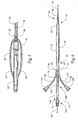
- the stent introducer apparatus 10 includes a handle 20, an introducer catheter 50, a guide wire 70 and a stent 90.
- the handle has a portion that is slidable such that when the slidable portion of the handle slides from a distal end 24 to a proximal end 22 (i.e., in a distal direction), the catheter proximal end 52 also travels toward the handle proximal end 22, thereby causing a stent 90 that is preloaded onto the guide wire 70 (disposed within the catheter 50) to be exposed and deployed.
- preferred stents are the self-expanding biliary stent sold as SPIRAL ZTM and ZA-STENTTM sold by Wilson-Cook Medical, Inc.
- the handle 20 has a proximal end 22 and a distal end 24.
- the handle 20 also has a slidable portion that can slide coaxially from the distal end 24 to the proximal end 22 and vice versa.
- the handle comprises an outer portion 26 and an inner portion 28, with the outer portion 26 slidable over the inner portion 28.
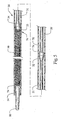
- the catheter 50 has a proximal end 52 and a distal end 54. As best seen in FIG. 2 , the catheter proximal end 52 is slit longitudinally to produce a first slit 60 and a second slit 62 to respectively define a first tab 64 and a second tab 66. The first tab 64 is located on one side of the catheter 50 while the second tab 66 is located on the other or opposite side of the catheter. Each slit 60, 62 extends to a respective closed end 61, 63 that is located between the proximal end 52 and the distal end 54 of the catheter 50.
- first 64 and second 66 tabs are each attached to the slidable portion of the handle 20 and, in particular to the handle outer portion 26.
- the tabs 64, 66 may be attached to the inside of the outer portion 26 or, as best seen in FIG. 3 , to the outside of the outer portion 26.
- the catheter 50 may be made from any suitable material and is preferably made from a clear material such as a substantially clear polymer. Suitable materials include, but are not limited to, polytetrafluoroethylene (PTFE) and polyeretherketone (PEEK).
- the catheter 50 can comprise a thin-walled tube of a longitudinally molecularly oriented, anisotropic material such as PTFE whose molecular properties permit it to be torn longitudinally along a predetermined split line.
- a method for molecularly orienting is disclosed in U.S. Pat. No. 4,306,562 , the relevant contents of which are incorporated herein by reference.
- longitudinal tearing can be accomplished by pre-weakening the sheath by the formation of one or more grooves or the like in the wall of the sheath so that the sheath tears along the grooves.
- a guide wire 70 is preferably provided within the catheter 50.
- the guide wire 70 has a proximal end 72 and a distal end 74.
- the distal end 74 is provided with a stent-carrying section 76.
- the stent-carrying section 76 has an outside diameter smaller than the outside diameter of the adjacent or other portions of the guide wire 70 so that when the stent 90 is loaded onto the stent-carrying section 76, the resulting thickness or diameter of the stent 90 and stent-carrying section 76 is not greater than the diameter of the adjacent portion of the guide wire 70.
- the guide wire 70 may be made of any suitable material such as PEEK, polyvinyl chloride (PVC), polyimide, polyimide reinforced with a stainless steel braid, polyurethane, nylon, metal tubing such as nitinol or stainless steel, and the like.
- the guide wire 70 may also be formed as a coil or a solid-core wire guide. In one embodiment, a substantial portion of the guide wire 70 is formed from nylon tubing while the distal portion, and especially the stent-carrying section, is formed from polyimide.
- the guide wire 70 could comprise an inner sheath or catheter, often referred to as a pusher member, with a lumen extending longitudinally through the interior thereof.
- the inner catheter would be movably disposed within the catheter 50, and the inner catheter would comprise a stent-carrying section on the distal end portion thereof.
- a separate guide wire 78 would extend through the inner catheter.
- the separate guide wire 78 which extends through the entire length of the introducer apparatus 10, may be employed by the user to navigate the internal body lumen of the patient.
- guide wire 78 could be made of any suitable material or comprise any of the features described above in connection with wire guide 70.
- a tip 80 formed of a soft material such as a soft polymer with good bonding properties is provided so that it can be bonded or attached to the catheter distal end 74 of the guide wire 54.
- the tip 80 and the catheter distal end 74 are tapered and/or rounded to facilitate an atraumatic entry into a body lumen.
- the tip 80 may include barium sulfate or some other agent or marker to provide radiopacity.
- the handle distal end 24 is provided with an adapter 40 that contacts the guide wire proximal end 72 and also provides a surface over which a portion of the tabs 64,66 of the catheter 50 will pass to more easily propagate the slits 60,62 in the catheter 50 in a longitudinal direction.
- the adapter 40 has a nose 42 that may further be provided with a push rod 44.
- the push rod 44 has approximately the same diameter as the guide wire 70 so that substantial contact will be made between the ends of the push rod 44 and the guide wire 70.
- the adapter 40 has a pair of guide slots 46 that receive a respective portion of the tabs 64, 66.
- the tabs 64,66 are less likely to become tangled or obstructed as the tabs 64,66 are pulled in the proximal direction relative to the guide wire 70.
- the guide slots 46 likewise reduce the likelihood that the tabs 64, 66 will interfere with a user's ability to grasp the adapter 40.
- the propagation of the slits 60, 62 is enhanced by maintaining the separation of the tabs.
- the catheter distal end 54 is delivered to the desired location. Once the catheter distal end 54 is in the correct position for deployment of the stent 90, the slidable portion of the handle 20 is retracted in a proximal axial direction (i.e., pulled from the distal end toward the proximal end). This action pulls the proximal end of the catheter 52 toward the proximal end of the handle 22, which thereby causes the distal end of the handle 24 to contact and propagate the slits 60, 62 in the direction toward the distal end 54 of the catheter 50.
- the catheter 50 is traveling toward the proximal end of the handle 22, and because the guide wire 70 is prevented from traveling by contact with the distal end of the handle 24, the distal end of the guide wire 74 becomes exposed. In turn, the stent 90 becomes exposed and obtains a deployed position. Thereafter, the catheter 50 and guide wire 70 can be retracted from the desired location, leaving the deployed stent 90 behind.
- a handle 120 is provided at the proximal end of the guide wire 72.
- the handle 120 may be formed of any suitable material and its construction is not critical.
- the handle 120 is provided so that the user will be able to securely hold the guide wire 70 when it is desired to deploy the stent 90.
- the tabs 64, 66 are provided with knobs 164,166 respectively.
- the knobs 164,166 are known in the art and may simply be a knob that screws into a socket. The force between the screw and the socket maintains the end of the tab in position.
- the knobs 164,166 are provided to allow the user to firmly grasp the tabs 64, 66 when it is desired to deploy the stent 90.
- An adapter 140 is provided to aid in propagating the slits 60, 62 in the longitudinal direction toward the distal end of the catheter 54.
- the adapter 140 has a distal end 142 and a proximal end 144, with the proximal end 144 being adjacent the proximal end of the guide wire 72.
- the adapter 140 surrounds a portion of the guide wire 70 near the proximal end of the guide wire 72.
- the adapter 140 is immovable with respect to the guide wire 70 and is preferably a material that is compatible with the other materials used in the construction of the apparatus of the present invention.
- the distal end of the catheter 54 is delivered to the desired location.
- one person grasps the handle 120 while another person grasps each of the knobs 164,166 and pulls the knobs toward the proximal end of the guide wire 72.
- This action pulls the proximal end of the catheter 52 toward the handle 20 and contact with the distal end of the handle 124, which in turn causes the slits 60, 62 to propagate in the direction toward the distal end of the catheter 54.
- the catheter 50 is traveling toward the proximal end of the handle 122, and because the guide wire 70 is prevented from traveling, the distal end of the guide wire 74 becomes exposed.
- the stent 90 becomes exposed and obtains a deployed position. Thereafter, the catheter 50 and guide wire 70 can be retracted from the desired location, leaving the stent 90 behind.
- FIG. 5 a partial section view of the distal end of one embodiment of the apparatus of the present invention is shown.
- the pusher assembly 30 includes a tubular portion 31 that has one end connected to the distal end 74 of the guide wire 70 preferably through a tapered portion 32.
- the other end of the tubular portion 31 includes a pusher head 34 that contacts the stent 90 to push the stent 90 from the introducer catheter 50.
- the pusher head 34 and the tapered portion may be formed of a separate material or may be integral with the tubular portion 31. Where it is formed of a separate material, it may be made of metal or plastic and may be secured to the tubular portion by gluing or other well known securing methods.
- the pusher head has a broad face 35 to contact one end of the stent 90 to urge the stent 90 forward until the stent 90 is deployed. It should be understood that the pusher assembly 30 can be incorporated into any of the above-described embodiments of the stent introducer apparatus.
Landscapes
- Health & Medical Sciences (AREA)
- Engineering & Computer Science (AREA)
- Biomedical Technology (AREA)
- Cardiology (AREA)
- Oral & Maxillofacial Surgery (AREA)
- Transplantation (AREA)
- Heart & Thoracic Surgery (AREA)
- Vascular Medicine (AREA)
- Life Sciences & Earth Sciences (AREA)
- Animal Behavior & Ethology (AREA)
- General Health & Medical Sciences (AREA)
- Public Health (AREA)
- Veterinary Medicine (AREA)
- Media Introduction/Drainage Providing Device (AREA)
Claims (13)
- Stent-Einführungsvorrichtung (10), umfassend:einen Katheter (50) mit einem proximalen Endteil (52) und einem distalen Endteil (54);einen Führungsdraht (70), der innerhalb des Katheters (50) beweglich angeordnet ist, wobei der Führungsdraht (70) einen proximalen Endteil (72) und einen distalen Endteil (74) aufweist;einen einsetzbaren Stent (90), wobei der Stent (90) innerhalb des distalen Endteils des Katheters (54) angeordnet ist und von dem distalen Endteil des Führungsdrahts (74) gefasst wird; undeinen Handgriff (20), der fest mit dem proximalen Endteil des Führungsdrahts (72) verbunden ist,wobei der Stent (90) durch Bewegen des Katheters (50) in eine proximale Richtung relativ zu dem Führungsdraht (70) eingesetzt wird, dadurch gekennzeichnet, dass der proximale Endteil des Katheters (52) von dem Handgriff (20) geteilt wird, wenn der Katheter (50) in die proximale Richtung bewegt wird, undwobei der Handgriff (20) einen ersten Teil (26) und einen zweiten Teil (28) umfasst, wobei der erste Teil (26) relativ zu dem zweiten Teil (28) axial beweglich ist, wobei ferner der proximale Endteil des Katheters (52) mit dem ersten Teil (26) verbunden ist und der proximale Endteil des Führungsdrahts (72) mit dem zweiten Teil (28) verbunden ist, wodurch Bewegung des ersten Teils (26) relativ zu dem zweiten Teil (28) bewirkt, dass der proximale Endteil des Katheters (52) von dem zweiten Teil des Handgriffs (28) geteilt wird.
- Stent-Einführungsvorrichtung (10) gemäß Anspruch 1, wobei der proximale Endteil des Katheters (52) einen oder mehrere Streifen (64, 66) umfasst, die mit dem ersten Teil des Handgriffs (26) verbunden sind.
- Stent-Einführungsvorrichtung (10) gemäß Anspruch 2, wobei jeder der Streifen (64, 66) durch eine Öffnung (46) in dem zweiten Teil des Handgriffs (28) hindurchtritt.
- Stent-Einführungsvorrichtung (10) gemäß Ansprüchen 1, 2 oder 3, wobei der zweite Teil (28) einen Adapter (40) umfasst, der dafür gestaltet ist, den proximalen Endteil des Katheters (52) zu fassen und zu teilen.
- Stent-Einführungsvorrichtung (10) gemäß Anspruch 4, wobei der Adapter (40) eine Nase (42) umfasst, die dafür gestaltet ist, den proximalen Endteil des Katheters (52) von dem Führungsdraht (70) zu trennen.
- Stent-Einführungsvorrichtung (10) gemäß Anspruch 5, wobei die Nase (42) eine abgeschrägte Oberfläche aufweist, die dafür ausgelegt ist, den proximalen Endteil des Katheters (52) in eine Vielzahl von Streifenteilen (64, 66) zu teilen, wenn der Katheter (50) in die proximale Richtung bewegt wird.
- Stent-Einführungsvorrichtung (10) gemäß einem der vorstehenden Ansprüche, wobei der proximale Endteil des Katheters (52) einen longitudinal angeordneten geschwächten Bereich aufweist, um das Teilen des Katheters (50) durch den Handgriff (20), wenn der Katheter (50) in die proximale Richtung bewegt wird, zu erleichtern.
- Stent-Einführungsvorrichtung (10) gemäß einem der vorstehenden Ansprüche, wobei der distale Endteil des Führungsdrahts (74) eine Schieberbaugruppe (30) umfasst, die dafür ausgelegt ist, den Stent (90) zu fassen, wobei die Schieberbaugruppe (30) einen Schieberkopf (34) umfasst, der dafür ausgelegt ist, ein proximales Ende des Stents (90) zu fassen.
- Stent-Einführungsvorrichtung (10) gemäß Anspruch 8, wobei der distale Endteil des Führungsdrahts (74) ferner eine Endkappe (80) umfasst, wobei die Endkappe (80) benachbart zu einem distalen Ende des Stents (90) angeordnet ist.
- Stent-Einführungsvorrichtung (10) gemäß Anspruch 9, wobei die Endkappe (80) durch einen Stent-tragenden Abschnitt (76) mit der Schieberbaugruppe (30) verbunden ist, wobei der Stent-tragende Abschnitt (76) zum Aufnehmen des Stents (90) darauf ausgelegt ist.
- Stent-Einführungsvorrichtung (10) gemäß einem der vorstehenden Ansprüche, wobei der Stent (90) einen selbstexpandierenden Stent umfasst, der eine komprimierte Konfiguration und eine expandierte eingesetzte Konfiguration aufweist, wobei der Stent (90) die komprimierte Konfiguration annimmt, wenn er in dem distalen Endteil des Katheters (54) angeordnet ist.
- Stent-Einführungsvorrichtung (10) gemäß einem der vorstehenden Ansprüche, wobei der Führungsdraht (70) einen inneren Katheter (30) mit einem longitudinal hindurch verlaufenden Lumen (31) umfasst.
- Stent-Einführungsvorrichtung (10) gemäß Anspruch 12, ferner umfassend einen inneren Führungsdraht (78), der beweglich durch das Lumen (31) des inneren Katheters (30) verläuft.
Applications Claiming Priority (3)
| Application Number | Priority Date | Filing Date | Title |
|---|---|---|---|
| US38494302P | 2002-05-31 | 2002-05-31 | |
| US384943P | 2002-05-31 | ||
| PCT/US2003/017439 WO2003101347A1 (en) | 2002-05-31 | 2003-05-30 | Stent introducer apparatus |
Publications (2)
| Publication Number | Publication Date |
|---|---|
| EP1513472A1 EP1513472A1 (de) | 2005-03-16 |
| EP1513472B1 true EP1513472B1 (de) | 2015-12-09 |
Family
ID=29712108
Family Applications (1)
| Application Number | Title | Priority Date | Filing Date |
|---|---|---|---|
| EP03756378.0A Expired - Lifetime EP1513472B1 (de) | 2002-05-31 | 2003-05-30 | Gerät zur einführung eines stents |
Country Status (4)
| Country | Link |
|---|---|
| US (1) | US7314481B2 (de) |
| EP (1) | EP1513472B1 (de) |
| AU (1) | AU2003247474A1 (de) |
| WO (1) | WO2003101347A1 (de) |
Families Citing this family (73)
| Publication number | Priority date | Publication date | Assignee | Title |
|---|---|---|---|---|
| US7018401B1 (en) | 1999-02-01 | 2006-03-28 | Board Of Regents, The University Of Texas System | Woven intravascular devices and methods for making the same and apparatus for delivery of the same |
| US6261316B1 (en) | 1999-03-11 | 2001-07-17 | Endologix, Inc. | Single puncture bifurcation graft deployment system |
| US8034100B2 (en) * | 1999-03-11 | 2011-10-11 | Endologix, Inc. | Graft deployment system |
| US7219799B2 (en) * | 2002-12-31 | 2007-05-22 | Possis Medical, Inc. | Packaging system with oxygen sensor |
| US6989024B2 (en) | 2002-02-28 | 2006-01-24 | Counter Clockwise, Inc. | Guidewire loaded stent for delivery through a catheter |
| US20050209672A1 (en) * | 2004-03-02 | 2005-09-22 | Cardiomind, Inc. | Sliding restraint stent delivery systems |
| US20040193178A1 (en) * | 2003-03-26 | 2004-09-30 | Cardiomind, Inc. | Multiple joint implant delivery systems for sequentially-controlled implant deployment |
| US7771463B2 (en) * | 2003-03-26 | 2010-08-10 | Ton Dai T | Twist-down implant delivery technologies |
| EP1608299B1 (de) * | 2003-03-26 | 2010-05-12 | Cardiomind, Inc. | Implantatablage-katheter mit elektrolytisch abbaubaren verbindungen |
| US7967829B2 (en) * | 2003-10-09 | 2011-06-28 | Boston Scientific Scimed, Inc. | Medical device delivery system |
| JP4721276B2 (ja) * | 2003-10-15 | 2011-07-13 | 株式会社 京都医療設計 | 脈管用ステント供給装置 |
| US7876738B2 (en) * | 2004-03-02 | 2011-01-25 | Nokia Corporation | Preventing an incorrect synchronization between a received code-modulated signal and a replica code |
| US20050209670A1 (en) * | 2004-03-02 | 2005-09-22 | Cardiomind, Inc. | Stent delivery system with diameter adaptive restraint |
| US7651521B2 (en) * | 2004-03-02 | 2010-01-26 | Cardiomind, Inc. | Corewire actuated delivery system with fixed distal stent-carrying extension |
| US20050209671A1 (en) * | 2004-03-02 | 2005-09-22 | Cardiomind, Inc. | Corewire actuated delivery system with fixed distal stent-carrying extension |
| US20060085057A1 (en) * | 2004-10-14 | 2006-04-20 | Cardiomind | Delivery guide member based stent anti-jumping technologies |
| US7921874B2 (en) * | 2004-11-12 | 2011-04-12 | Cook Medical Technologies Llc | Flow variation valve assembly |
| US20070073379A1 (en) * | 2005-09-29 | 2007-03-29 | Chang Jean C | Stent delivery system |
| WO2007013902A2 (en) * | 2005-06-20 | 2007-02-01 | Wilson-Cook Medical Inc. | Single peel stent introducer apparatus |
| US8118852B2 (en) * | 2005-07-13 | 2012-02-21 | Cook Medical Technologies Llc | Introducer for self-expandable medical device |
| BRPI0615567A2 (pt) * | 2005-09-19 | 2012-12-11 | Minvasys | aparelho e métodos para angioplastia e aplicação de stent protegida em uma bifurcação da carótida |
| US20070100414A1 (en) * | 2005-11-02 | 2007-05-03 | Cardiomind, Inc. | Indirect-release electrolytic implant delivery systems |
| AU2006330816B2 (en) | 2005-12-23 | 2012-05-24 | Cook Medical Technologies Llc | Prosthesis deployment system |
| US20070185524A1 (en) * | 2006-02-03 | 2007-08-09 | Pedro Diaz | Rapid exchange emboli capture guidewire system and methods of use |
| US20070198076A1 (en) * | 2006-02-13 | 2007-08-23 | Stephen Hebert | System for delivering a stent |
| US20080071343A1 (en) * | 2006-09-15 | 2008-03-20 | Kevin John Mayberry | Multi-segmented graft deployment system |
| CA2934202A1 (en) | 2006-10-22 | 2008-05-02 | Idev Technologies, Inc. | Methods for securing strand ends and the resulting devices |
| MX344492B (es) | 2006-10-22 | 2016-12-16 | Idev Tech Inc * | Dispositivos y métodos para el avance de stent. |
| US20080221666A1 (en) * | 2006-12-15 | 2008-09-11 | Cardiomind, Inc. | Stent systems |
| US9149379B2 (en) * | 2007-07-16 | 2015-10-06 | Cook Medical Technologies Llc | Delivery device |
| US9144508B2 (en) | 2007-07-19 | 2015-09-29 | Back Bay Medical Inc. | Radially expandable stent |
| EP2227185B1 (de) * | 2007-11-07 | 2013-05-01 | Cook Medical Technologies LLC | Gerät zur einführung von expandierbaren intraluminalen prothesen |
| US20090171279A1 (en) * | 2007-12-26 | 2009-07-02 | Cook Incorporated | Balloon catheter assembly and controller therefor |
| WO2009086512A2 (en) * | 2007-12-28 | 2009-07-09 | Boston Endoscopic Engineering Corp. | Exchangeable guide-wire with balloon for foreign body extraction |
| US8221494B2 (en) | 2008-02-22 | 2012-07-17 | Endologix, Inc. | Apparatus and method of placement of a graft or graft system |
| US8236040B2 (en) * | 2008-04-11 | 2012-08-07 | Endologix, Inc. | Bifurcated graft deployment systems and methods |
| US8882821B2 (en) * | 2008-05-02 | 2014-11-11 | Cook Medical Technologies Llc | Cartridge delivery system for delivery of medical devices |
| US20090306760A1 (en) * | 2008-06-06 | 2009-12-10 | Bay Street Medical | Prosthesis and delivery system |
| EP2520320B1 (de) | 2008-07-01 | 2016-11-02 | Endologix, Inc. | Kathetersystem |
| US9782565B2 (en) | 2008-10-01 | 2017-10-10 | Covidien Lp | Endoscopic ultrasound-guided biliary access system |
| US9332973B2 (en) | 2008-10-01 | 2016-05-10 | Covidien Lp | Needle biopsy device with exchangeable needle and integrated needle protection |
| US9186128B2 (en) | 2008-10-01 | 2015-11-17 | Covidien Lp | Needle biopsy device |
| US8968210B2 (en) | 2008-10-01 | 2015-03-03 | Covidien LLP | Device for needle biopsy with integrated needle protection |
| US11298113B2 (en) | 2008-10-01 | 2022-04-12 | Covidien Lp | Device for needle biopsy with integrated needle protection |
| WO2010078352A1 (en) * | 2008-12-30 | 2010-07-08 | Wilson-Cook Medical Inc. | Delivery device |
| JP5629871B2 (ja) | 2009-04-28 | 2014-11-26 | エンドロジックス、インク | 移植片あるいは移植片システムを配置する装置および方法 |
| US8657870B2 (en) * | 2009-06-26 | 2014-02-25 | Biosensors International Group, Ltd. | Implant delivery apparatus and methods with electrolytic release |
| WO2011094527A1 (en) * | 2010-01-29 | 2011-08-04 | Cook Medical Technologies Llc | Mechanically expandable delivery and dilation systems |
| US9023095B2 (en) | 2010-05-27 | 2015-05-05 | Idev Technologies, Inc. | Stent delivery system with pusher assembly |
| US20110301684A1 (en) * | 2010-06-08 | 2011-12-08 | Svelte Medical Systems, Inc. | System and method for performing angiography and stenting |
| CA2806234C (en) | 2010-07-30 | 2015-03-24 | Cook Medical Technologies Llc | Controlled release and recapture prosthetic deployment device |
| US10111767B2 (en) | 2010-10-29 | 2018-10-30 | Abbott Cardiovascular Systems Inc. | Sheaths used in polymer scaffold delivery systems |
| EP2635241B1 (de) | 2010-11-02 | 2019-02-20 | Endologix, Inc. | Vorrichtung zur positionierung einer gefässprothese bzw. eines gefässprothesensystems |
| US8657866B2 (en) * | 2010-12-22 | 2014-02-25 | Cook Medical Technologies Llc | Emergency vascular repair prosthesis deployment system |
| CN103561807B (zh) | 2011-03-01 | 2015-11-25 | 恩朵罗杰克斯股份有限公司 | 导管系统及其使用方法 |
| US8414528B2 (en) | 2011-05-27 | 2013-04-09 | Abbott Cardiovascular Systems Inc. | Polymer scaffold sheaths |
| US8852257B2 (en) | 2011-06-21 | 2014-10-07 | Abbott Cardiovascular Systems Inc. | Sheaths used with polymer scaffold |
| US9072590B2 (en) | 2012-12-07 | 2015-07-07 | Abbott Cardiovascular Systems Inc. | Sheaths reducing recoil and loss of retention for polymer scaffolds crimped to balloons |
| US9849015B2 (en) * | 2012-12-28 | 2017-12-26 | Cook Medical Technologies Llc | Endoluminal prosthesis introducer |
| US9308108B2 (en) | 2013-03-13 | 2016-04-12 | Cook Medical Technologies Llc | Controlled release and recapture stent-deployment device |
| US10206747B2 (en) * | 2013-05-15 | 2019-02-19 | Intuitive Surgical Operations, Inc. | Guide apparatus for delivery of a flexible instrument and methods of use |
| US9788983B2 (en) | 2013-06-21 | 2017-10-17 | Abbott Cardiovascular Systems Inc. | Removable sheath assembly for a polymer scaffold |
| US9675483B2 (en) | 2013-06-21 | 2017-06-13 | Abbott Cardiovascular Systems Inc. | Protective sheath assembly for a polymer scaffold |
| US10098771B2 (en) | 2013-09-25 | 2018-10-16 | Abbott Cardiovascular Systems Inc. | Clip sheath for a polymer scaffold |
| US9913958B2 (en) | 2014-02-28 | 2018-03-13 | Abbott Cardiovascular Systems Inc. | Protective sheaths for medical devices |
| US9364361B2 (en) | 2014-03-13 | 2016-06-14 | Abbott Cardiovascular Systems Inc. | Striped sheaths for medical devices |
| US10137020B2 (en) | 2014-12-09 | 2018-11-27 | Cook Medical Technologies Llc | Two pronged handle |
| CN111529126A (zh) | 2015-06-30 | 2020-08-14 | 恩朵罗杰克斯股份有限公司 | 用于将第一细长构件固定至第二细长构件的系统及方法 |
| AU2015215913B1 (en) * | 2015-08-20 | 2016-02-25 | Cook Medical Technologies Llc | An endograft delivery device assembly |
| US20220000601A1 (en) * | 2018-11-15 | 2022-01-06 | Baleen Medical Llc | Methods, systems, and devices for embolic protection |
| CN211856471U (zh) | 2019-08-22 | 2020-11-03 | 贝克顿·迪金森公司 | 回声医疗器械回声反射性量化测试系统 |
| CN211884905U (zh) | 2019-08-22 | 2020-11-10 | 贝克顿·迪金森公司 | 球囊扩张导管及其球囊 |
| CN112401971B (zh) | 2019-08-23 | 2025-09-09 | 贝克顿·迪金森公司 | 为经皮肾镜取石术外科手术设计的套件 |
Family Cites Families (31)
| Publication number | Priority date | Publication date | Assignee | Title |
|---|---|---|---|---|
| USRE31855F1 (en) | 1978-12-01 | 1986-08-19 | Tear apart cannula | |
| US4306562A (en) | 1978-12-01 | 1981-12-22 | Cook, Inc. | Tear apart cannula |
| US4581026A (en) * | 1981-06-05 | 1986-04-08 | Hollister Incorporated | Male urinary collection system and external catheter therefor |
| US4581025A (en) | 1983-11-14 | 1986-04-08 | Cook Incorporated | Sheath |
| US4772266A (en) | 1987-05-04 | 1988-09-20 | Catheter Technology Corp. | Catheter dilator/sheath assembly and method |
| US5120299A (en) | 1987-05-22 | 1992-06-09 | Kontron Instruments, Inc. | Intra-aortic balloon assembly with hemostasis device |
| US4997424A (en) * | 1989-04-05 | 1991-03-05 | Medamicus, Inc. | Catheter introducer and introducer slitter |
| US5158545A (en) | 1991-05-02 | 1992-10-27 | Brigham And Women's Hospital | Diameter expansion cannula |
| US5167634A (en) | 1991-08-22 | 1992-12-01 | Datascope Investment Corp. | Peelable sheath with hub connector |
| US5222970A (en) | 1991-09-06 | 1993-06-29 | William A. Cook Australia Pty. Ltd. | Method of and system for mounting a vascular occlusion balloon on a delivery catheter |
| US5201757A (en) * | 1992-04-03 | 1993-04-13 | Schneider (Usa) Inc. | Medial region deployment of radially self-expanding stents |
| CA2102617C (en) | 1992-04-09 | 1996-06-11 | Peter J. Pohndorf | Lead introducer with mechanical opening valve |
| US5221263A (en) | 1992-07-30 | 1993-06-22 | Gesco International, Inc. | Catheter emplacement apparatus |
| US5250033A (en) | 1992-10-28 | 1993-10-05 | Interventional Thermodynamics, Inc. | Peel-away introducer sheath having proximal fitting |
| US5415639A (en) | 1993-04-08 | 1995-05-16 | Scimed Life Systems, Inc. | Sheath and method for intravascular treatment |
| US5425717A (en) | 1993-05-07 | 1995-06-20 | The Kendall Company | Epidural catheter system utilizing splittable needle |
| US5320602A (en) | 1993-05-14 | 1994-06-14 | Wilson-Cook Medical, Inc. | Peel-away endoscopic retrograde cholangio pancreatography catheter and a method for using the same |
| US5536255A (en) | 1994-10-03 | 1996-07-16 | Moss; Gerald | Dilator/introducer apparatus for percutaneous gastrostomy |
| US5489273A (en) | 1994-10-07 | 1996-02-06 | Tfx Medical, Incorporated | Introducer device and methods of use thereof |
| US5591226A (en) | 1995-01-23 | 1997-01-07 | Schneider (Usa) Inc. | Percutaneous stent-graft and method for delivery thereof |
| US5534007A (en) * | 1995-05-18 | 1996-07-09 | Scimed Life Systems, Inc. | Stent deployment catheter with collapsible sheath |
| US5766203A (en) * | 1995-07-20 | 1998-06-16 | Intelliwire, Inc. | Sheath with expandable distal extremity and balloon catheters and stents for use therewith and method |
| US5630830A (en) | 1996-04-10 | 1997-05-20 | Medtronic, Inc. | Device and method for mounting stents on delivery systems |
| US5735819A (en) | 1996-08-02 | 1998-04-07 | Cook Incorporated | Tear-apart member for positioning a grommet carried thereon |
| US5919160A (en) | 1996-10-10 | 1999-07-06 | Sanfilippo, Ii; Dominic Joseph | Vascular access device and method of installing same |
| FR2754718B1 (fr) | 1996-10-18 | 1998-11-13 | Synthelabo | Catheter a corps souple allonge |
| DE69737208T2 (de) | 1996-11-15 | 2007-11-08 | Cook Inc., Bloomington | Stentanbringungsvorrichtung mit einer auftrennbaren hülle |
| US5951518A (en) | 1997-10-31 | 1999-09-14 | Teleflex, Incorporated | Introducing device with flared sheath end |
| US6093194A (en) | 1998-09-14 | 2000-07-25 | Endocare, Inc. | Insertion device for stents and methods for use |
| DE19936980C1 (de) | 1999-08-05 | 2001-04-26 | Aesculap Ag & Co Kg | Einführkatheter für Gefäßprothesen |
| USD450839S1 (en) | 2000-02-07 | 2001-11-20 | Larry G. Junker | Handle for introducer sheath |
-
2003
- 2003-05-30 EP EP03756378.0A patent/EP1513472B1/de not_active Expired - Lifetime
- 2003-05-30 US US10/449,730 patent/US7314481B2/en not_active Expired - Lifetime
- 2003-05-30 WO PCT/US2003/017439 patent/WO2003101347A1/en not_active Ceased
- 2003-05-30 AU AU2003247474A patent/AU2003247474A1/en not_active Abandoned
Also Published As
| Publication number | Publication date |
|---|---|
| US20040010265A1 (en) | 2004-01-15 |
| WO2003101347A1 (en) | 2003-12-11 |
| AU2003247474A1 (en) | 2003-12-19 |
| EP1513472A1 (de) | 2005-03-16 |
| US7314481B2 (en) | 2008-01-01 |
Similar Documents
| Publication | Publication Date | Title |
|---|---|---|
| EP1513472B1 (de) | Gerät zur einführung eines stents | |
| US8025691B2 (en) | Single peel stent introducer apparatus | |
| EP2227185B1 (de) | Gerät zur einführung von expandierbaren intraluminalen prothesen | |
| EP1408873B1 (de) | Katheter | |
| US7780693B2 (en) | Catheter | |
| EP3072479B1 (de) | Katheter | |
| EP1202676B1 (de) | Medizinische fassvorrichtung | |
| US8506615B2 (en) | Implantable medical endoprosthesis delivery system | |
| EP1399085B1 (de) | Katheter | |
| US20070203563A1 (en) | System for delivering a stent | |
| JP2007518518A (ja) | ステントデリバリカテーテル | |
| CN110913777B (zh) | 可塌缩扩张器 | |
| US20250032290A1 (en) | Delivery systems for endoluminal prostheses and methods of use | |
| US20090112253A1 (en) | Guidewire for embolic device | |
| US20070043390A1 (en) | Delivery catheter | |
| IE20020529A1 (en) | A Catheter | |
| IE20060620A1 (en) | A delivery catheter | |
| AU2002345312A1 (en) | A catheter | |
| AU2002345311A1 (en) | A catheter |
Legal Events
| Date | Code | Title | Description |
|---|---|---|---|
| PUAI | Public reference made under article 153(3) epc to a published international application that has entered the european phase |
Free format text: ORIGINAL CODE: 0009012 |
|
| 17P | Request for examination filed |
Effective date: 20041215 |
|
| AK | Designated contracting states |
Kind code of ref document: A1 Designated state(s): AT BE BG CH CY CZ DE DK EE ES FI FR GB GR HU IE IT LI LU MC NL PT RO SE SI SK TR |
|
| AX | Request for extension of the european patent |
Extension state: AL LT LV MK |
|
| DAX | Request for extension of the european patent (deleted) | ||
| RBV | Designated contracting states (corrected) |
Designated state(s): DE GB IE |
|
| 17Q | First examination report despatched |
Effective date: 20081001 |
|
| RAP1 | Party data changed (applicant data changed or rights of an application transferred) |
Owner name: COOK MEDICAL TECHNOLOGIES LLC |
|
| RAP1 | Party data changed (applicant data changed or rights of an application transferred) |
Owner name: COOK MEDICAL TECHNOLOGIES LLC |
|
| GRAP | Despatch of communication of intention to grant a patent |
Free format text: ORIGINAL CODE: EPIDOSNIGR1 |
|
| INTG | Intention to grant announced |
Effective date: 20150424 |
|
| GRAP | Despatch of communication of intention to grant a patent |
Free format text: ORIGINAL CODE: EPIDOSNIGR1 |
|
| INTG | Intention to grant announced |
Effective date: 20150911 |
|
| GRAS | Grant fee paid |
Free format text: ORIGINAL CODE: EPIDOSNIGR3 |
|
| GRAA | (expected) grant |
Free format text: ORIGINAL CODE: 0009210 |
|
| AK | Designated contracting states |
Kind code of ref document: B1 Designated state(s): DE GB IE |
|
| REG | Reference to a national code |
Ref country code: GB Ref legal event code: FG4D |
|
| REG | Reference to a national code |
Ref country code: IE Ref legal event code: FG4D |
|
| REG | Reference to a national code |
Ref country code: DE Ref legal event code: R096 Ref document number: 60348328 Country of ref document: DE |
|
| REG | Reference to a national code |
Ref country code: DE Ref legal event code: R097 Ref document number: 60348328 Country of ref document: DE |
|
| PLBE | No opposition filed within time limit |
Free format text: ORIGINAL CODE: 0009261 |
|
| STAA | Information on the status of an ep patent application or granted ep patent |
Free format text: STATUS: NO OPPOSITION FILED WITHIN TIME LIMIT |
|
| 26N | No opposition filed |
Effective date: 20160912 |
|
| PGFP | Annual fee paid to national office [announced via postgrant information from national office to epo] |
Ref country code: IE Payment date: 20220425 Year of fee payment: 20 Ref country code: GB Payment date: 20220421 Year of fee payment: 20 Ref country code: DE Payment date: 20220411 Year of fee payment: 20 |
|
| REG | Reference to a national code |
Ref country code: DE Ref legal event code: R071 Ref document number: 60348328 Country of ref document: DE |
|
| REG | Reference to a national code |
Ref country code: GB Ref legal event code: PE20 Expiry date: 20230529 |
|
| P01 | Opt-out of the competence of the unified patent court (upc) registered |
Effective date: 20230602 |
|
| PG25 | Lapsed in a contracting state [announced via postgrant information from national office to epo] |
Ref country code: IE Free format text: LAPSE BECAUSE OF EXPIRATION OF PROTECTION Effective date: 20230530 |
|
| PG25 | Lapsed in a contracting state [announced via postgrant information from national office to epo] |
Ref country code: GB Free format text: LAPSE BECAUSE OF EXPIRATION OF PROTECTION Effective date: 20230529 |