EP2598086B1 - Protheseneinsetzungssystem mit gesteuerter freisetzung und retraktion - Google Patents
Protheseneinsetzungssystem mit gesteuerter freisetzung und retraktion Download PDFInfo
- Publication number
- EP2598086B1 EP2598086B1 EP11738926.2A EP11738926A EP2598086B1 EP 2598086 B1 EP2598086 B1 EP 2598086B1 EP 11738926 A EP11738926 A EP 11738926A EP 2598086 B1 EP2598086 B1 EP 2598086B1
- Authority
- EP
- European Patent Office
- Prior art keywords
- pusher
- keeper
- pusher member
- trigger
- sheath
- Prior art date
- Legal status (The legal status is an assumption and is not a legal conclusion. Google has not performed a legal analysis and makes no representation as to the accuracy of the status listed.)
- Active
Links
Images


Classifications
-
- A—HUMAN NECESSITIES
- A61—MEDICAL OR VETERINARY SCIENCE; HYGIENE
- A61F—FILTERS IMPLANTABLE INTO BLOOD VESSELS; PROSTHESES; DEVICES PROVIDING PATENCY TO, OR PREVENTING COLLAPSING OF, TUBULAR STRUCTURES OF THE BODY, e.g. STENTS; ORTHOPAEDIC, NURSING OR CONTRACEPTIVE DEVICES; FOMENTATION; TREATMENT OR PROTECTION OF EYES OR EARS; BANDAGES, DRESSINGS OR ABSORBENT PADS; FIRST-AID KITS
- A61F2/00—Filters implantable into blood vessels; Prostheses, i.e. artificial substitutes or replacements for parts of the body; Appliances for connecting them with the body; Devices providing patency to, or preventing collapsing of, tubular structures of the body, e.g. stents
- A61F2/95—Instruments specially adapted for placement or removal of stents or stent-grafts
- A61F2/9517—Instruments specially adapted for placement or removal of stents or stent-grafts handle assemblies therefor
-
- A—HUMAN NECESSITIES
- A61—MEDICAL OR VETERINARY SCIENCE; HYGIENE
- A61F—FILTERS IMPLANTABLE INTO BLOOD VESSELS; PROSTHESES; DEVICES PROVIDING PATENCY TO, OR PREVENTING COLLAPSING OF, TUBULAR STRUCTURES OF THE BODY, e.g. STENTS; ORTHOPAEDIC, NURSING OR CONTRACEPTIVE DEVICES; FOMENTATION; TREATMENT OR PROTECTION OF EYES OR EARS; BANDAGES, DRESSINGS OR ABSORBENT PADS; FIRST-AID KITS
- A61F2/00—Filters implantable into blood vessels; Prostheses, i.e. artificial substitutes or replacements for parts of the body; Appliances for connecting them with the body; Devices providing patency to, or preventing collapsing of, tubular structures of the body, e.g. stents
- A61F2/95—Instruments specially adapted for placement or removal of stents or stent-grafts
- A61F2/962—Instruments specially adapted for placement or removal of stents or stent-grafts having an outer sleeve
- A61F2/966—Instruments specially adapted for placement or removal of stents or stent-grafts having an outer sleeve with relative longitudinal movement between outer sleeve and prosthesis, e.g. using a push rod
-
- A—HUMAN NECESSITIES
- A61—MEDICAL OR VETERINARY SCIENCE; HYGIENE
- A61F—FILTERS IMPLANTABLE INTO BLOOD VESSELS; PROSTHESES; DEVICES PROVIDING PATENCY TO, OR PREVENTING COLLAPSING OF, TUBULAR STRUCTURES OF THE BODY, e.g. STENTS; ORTHOPAEDIC, NURSING OR CONTRACEPTIVE DEVICES; FOMENTATION; TREATMENT OR PROTECTION OF EYES OR EARS; BANDAGES, DRESSINGS OR ABSORBENT PADS; FIRST-AID KITS
- A61F2/00—Filters implantable into blood vessels; Prostheses, i.e. artificial substitutes or replacements for parts of the body; Appliances for connecting them with the body; Devices providing patency to, or preventing collapsing of, tubular structures of the body, e.g. stents
- A61F2/95—Instruments specially adapted for placement or removal of stents or stent-grafts
- A61F2002/9534—Instruments specially adapted for placement or removal of stents or stent-grafts for repositioning of stents
Definitions
- This invention relates to a medical device and, in particular to a delivery device for a self-expanding prosthesis and a method of delivering and deploying the prosthesis into a body lumen.
- a self-expanding prosthesis such as a stent may be introduced into a patient's body using a delivery device that includes a push-pull mechanism with an outer catheter coaxially slidably disposed over an inner catheter.
- the prosthesis is disposed in a circumferentially-restrained configuration at the distal end of the device between the inner catheter and the outer catheter.
- the prosthesis may be deployed by proximally pulling back the outer catheter relative to the inner catheter, exposing the prosthesis and allowing it to deploy/ circumferentially expand.
- the push-pull delivery device described above may have several shortcomings. For example, when using this conventional push-pull delivery device, a physician may inadvertently retract the outer catheter too far and prematurely deploy the prosthesis in an incorrect position within a body lumen. In that circumstance, repositioning the prosthesis may be difficult, if not impossible, because the prosthesis already will have radially self-expanded and engaged the body lumen.
- US 6254628 which is the prior art on which the two-part form of Claim 1 is based.
- a delivery device including a fixed outer catheter sheath and a longitudinally-movable pusher member that is configured to retract/advance in proximal/distal directions for deploying and recapturing/ resheathing an intraluminal prosthesis.
- distal and distal shall denote a position, direction, or orientation that is generally away from the physician (including any other person holding/ operating a device) and/or toward a treatment zone/patient. Accordingly, the terms “proximal” and “proximally” shall denote a position, direction, or orientation that is generally towards the physician. In FIGS. 1A-1C, 3A-3C, and 4A-4C , “distal” is generally to the right, and “proximal” is generally to the left.
- proximal is generally to the left.
- FIGS. 1A-4C embodiments of a delivery device for deploying a self-expanding prosthesis are shown.
- the delivery device is configured with the ability to resheath and reposition the prosthesis, thereby substantially increasing the control and accuracy of a deployment process as compared with conventional delivery devices.
- FIGS. 1A-1C show one embodiment of a delivery device 100, with reference to a method of use.
- the delivery device 100 includes a handle 102 with a handle body 104 and an elongate tubular sheath 106 fixedly attached to and extending distally from the handle body 104.
- An elongate pusher member 108 extends slidably through a longitudinal lumen 107 of the sheath 106.
- the handle body 104 is shown in a longitudinal cutaway view revealing the internal components of the handle 102.
- the interior of the handle 102 includes an advancement plate member 112 that is biased toward the proximal end of the pusher member 108.
- the advancement member 112 is shown as being biased by a coil spring 115, but other biasing means known in the art may be used.
- the advancement member 112 includes an advancement member aperture 114 through its thickness, through which the pusher member 108 extends.
- a trigger member 116 is pivotably mounted to the handle body 104 and is connected to or otherwise disposed in operative contact with the advancement member 112. When the pivot axis 117 is configured as shown, pivoting the lower portion of the trigger member 116 proximally toward the handle body 104 will pivot the upper portion of the trigger member 116 distally, pushing the advancement member 112 distally. When advanced distally by motivation from the trigger member 116, the advancement member 112 engages (in the manner described below with reference to FIGS. 2A-2B ) and pushes distally the pusher member 108.
- a keeper plate member 122 is also mounted to the handle body 104 and biased toward its proximal end against a keeper stop 123.
- the keeper member 122 is shown as being biased by a coil spring 125, but other biasing means known in the art may be used.
- the keeper member 122 includes a keeper member aperture 124 through its thickness, through which the pusher member 108 extends.
- the keeper member functions as a "parking brake" or retaining means that will prevent proximal movement of the pusher member 108 when engaged thereto.
- the sheath 106 may stretch distally and then - when attempting to relax and return to its original length - it may introduce backlash that would drive the pusher 108 proximally if it did't held in place.
- the proximal end of the pusher member 108 may include a handle or other grasping portion such as a ring 138 that will facilitate a user grasping the pusher member 108 and moving it proximally and/or distally (albeit in a generally less controlled fashion than by employing the advancement and keeper/retractor members 112, 122).
- a distal portion of the pusher member 108 is attached to an expandable prosthesis such as, for example, an intraluminal device embodied as a self-expanding stent 145 (which, because it is sheathed in lumen 107 is not clearly visible in FIG. 1A ).
- the stent 145 may be constrained by this attachment and/or by the sheath 106.
- the sheath and pusher member will be sufficiently flexible and elongate to introduce a prosthetic device into a patient's alimentary canal.
- the device 100 may be used to introduce a stent into a patient's esophagus (e.g., via the patient's mouth) or along an intestinal lumen.
- Device embodiments may be used through natural and/or surgically-created orifices, and may be practiced on a scale suitable for vascular stenting.
- FIGS. 2A-2B illustrate the principle of operation of the attachment member 112 and the keeper member 122 with pusher member 108 (as well as analogous components of the other embodiments herein). The operation is described with reference to an apertured locking/gripping plate 282 (analogous to those members 112, 122, which function in the same manner) and a through-rod 288 (analogous to the pusher member 108, which functions in the same manner).
- the locking plate 282 includes an aperture 284 through its thickness.
- the inner diameter of the aperture 284 is preferably about the same or somewhat greater than an outer diameter of the through-rod 288.
- the through-rod 288 when the long axis of the through-rod 288 is fully or nearly parallel or coaxial with the long axis of the aperture 284, the through-rod 288 can pass freely along its longitudinal axis through the aperture 284 (as indicated by linear motion arrows B), and/or the plate 282 may move freely along a length of the rod 288 (as indicated by linear motion arrows A).
- the through-rod 288 can pass freely along its longitudinal axis through the aperture 284 (as indicated by linear motion arrows B), and/or the plate 282 may move freely along a length of the rod 288 (as indicated by linear motion arrows A).
- FIG. 2A when the long axis of the through-rod 288 is fully or nearly parallel or coaxial with the long axis of the aperture 284, the through-rod 288 can pass freely along its longitudinal axis through the aperture 284 (as indicated by linear motion arrows B), and/or the plate 282 may move freely along a length of the rod 2
- the border of the aperture grips, captures, binds, and/or otherwise engages an exterior surface of the through-rod 288 (e.g., in the regions indicated by designator arrows X), preferably with sufficient force to substantially or completely prevent the through-rod 288 from moving longitudinally relative to the locking plate 282.
- the through-rod 288 can move freely therethrough when it is perpendicular to the locking plate 282, but will be engaged by the aperture when it is at a non-perpendicular angle relative to the locking plate.
- the relative angle of a locking plate/ keeper member to a through-rod/ pusher member is also controlled by a spring-biased angle of the locking plate/ keeper member.
- the external geometry of the through-rod 288 and the aperture 284 do not need to be the same (e.g., the aperture may be - for example - hexagonal, square, or circular, while the cross-sectional geometry of the through-rod may be - for example - elliptical, triangular, or pentagonal).
- This type of securement is well-known in the art and those of skill in the art will appreciate that various shapes of apertures and/or through-rods may be used within the scope of the present invention, including that the through-rod may be notched or otherwise frictionally-enhanced.
- FIG. 1A shows the device 100 in an unactuated state, with the stent 145 being sheathed. Actuation of the device 100 with stent deployment is described with reference to FIG. 1 B .
- a user will pivot the lower portion of the trigger 116 toward the handle body 104. This action inclines the advancement member 112 to a first angle where its aperture captures/ engages the pusher member 108 and pushes it forward/ distally.
- the keeper member 122 is disposed at an angle wherein its aperture 124 allows freely sliding distal-ward passage of the pusher member 108 therethrough.
- the proximal bias of the advancement member 112 moves it back to the default position shown in FIG. 1A .
- the proximal bias of the keeper member 122 generally retains it in the default position shown in FIG. 1A .
- Serial actuation of the trigger 116 will advance the pusher member 108 and overlying stent 145 distally out of the distal end of the sheath 106 as shown in FIG. 1B .
- a stent 145 e.g., into a patient's esophagus
- the stent 145 has been partially deployed such that it has expanded sufficiently to engage patient tissue, it may be difficult or impossible to move the stent longitudinally and/or rotationally without injuring the patient and/or damaging the stent if it remains expanded.
- the present device 100 provides for a resheathing function, described with reference to FIG. 1C .
- the stent 145 and deployment device 100 may be visualized during a stent-placement procedure by ultrasound and/or fluoroscopy (e.g., based upon the construction of the stent and/or inclusion of specific markers such as echogenic and/or radio-opaque markers included in/on the stent, the device, or any combination thereof).
- ultrasound and/or fluoroscopy e.g., based upon the construction of the stent and/or inclusion of specific markers such as echogenic and/or radio-opaque markers included in/on the stent, the device, or any combination thereof.
- Such visualization which may also be done using a camera-type device (e.g., optical or electronic endoscope), will enable a physician to monitor and carefully control deployment and - if needed - resheathing/recapture of an expandable prosthesis such as a stent, stent-graft, or other prosthetic device.
- a user may actuate (i.e., disengage the brake function of) the keeper member 122 by moving it to an angle generally perpendicular to the pusher member 108, which will release the pusher 108 and allow it to be moved proximally by the user pulling proximally on the loop 138.
- the keeper 122 may function as a resheathing trigger.
- a user will pivot the lower portion of the keeper 122 toward the handle body 104 sufficiently to release its engagement with the pusher 108 and then slide the keeper member 122 distally along the pusher 108.
- the user may then allow the keeper 122 to incline back to a first angle where its aperture captures/ engages the pusher member 108 and pulls it (pusher 108) back/ proximally (or, more accurately, is pushed back proximally by the bias of the spring 125).
- the keeper 122 is released, its proximal bias moves it back to the default position shown in FIG. 1A .
- the proximal bias of the advancement member 112 by spring 115 generally retains it in the default position shown in FIG. 1A , disposed at an angle wherein its aperture 114 allows freely sliding distal-ward passage of the pusher member 108 therethrough.
- the device may be constructed such that serial actuation of the keeper 122 will retract the pusher member 108 and overlying stent 145 proximally back into the distal end of the sheath 106 as shown in FIG. 1 C , which shows the stent 145 having been partially resheathed. Thereafter, the longitudinal position of the device 100 (with the sheathed stent 145) may be adjusted as desired, and the stent deployed as desired, in the manner described above with reference to FIGS. 1A-1 B .
- FIGS. 3A-3B show another embodiment of a delivery device 300, with reference to a method of use.
- the delivery device 300 includes a handle 302 with a handle body 304 and an elongate tubular sheath 306 fixedly attached to and extending distally from the handle body 304.
- the flexible joint regions 309 are configured to allow a proximal portion of the pusher member 308 to coil/fold up within the handle body 304.
- the handle body 304 is shown in a longitudinal section view revealing the internal components of the handle 302.
- the interior of the handle 302 includes an advancement member 312 that is biased toward the proximal end of the pusher member 308.
- the advancement member 312 is shown as being biased proximally by a coil spring 315, but other biasing means known in the art may be used.
- the advancement member 312 includes an advancement member aperture 314 through its thickness, through which the pusher member 308 extends.
- a deployment/advancement trigger member 316 is pivotably mounted to the handle body 304 and is connected to or otherwise disposed in mechanical communication (e.g., operative contact) with the advancement member 312.
- pivoting the lower portion of the trigger member 316 proximally toward the handle body 304 will pivot the upper portion of the trigger member 316 distally, pushing the advancement member 312 distally.
- the advancement member 312 engages the pusher member 312 (in the manner described above with reference to FIGS. 2A-2B ) and pushes it distally.
- a keeper member 322 is mounted within an upper portion of the handle body 304 and biased toward its proximal end against a keeper stop.
- the keeper member 322 is shown as being biased by a distally/pulling-tensioned coil spring 325, but other biasing means known in the art may be used.
- the keeper member 322 includes an advancement member aperture 324 through its thickness, through which the pusher member 308 extends. The keeper member 322 thus is also in mechanical communication with the pusher member 308.
- a distal portion of the pusher member 308 is attached to an expandable prosthesis such as, for example, a self-expanding stent 345.
- the stent 345 may be constrained by this attachment and/or by the sheath 306.
- a variety of methods and constructions are known and are being developed in the art for providing stent attachment and deployment from a central pusher member whether or not it is accompanied by an outer sheath. Many of these constructions and methods may be practiced in a useful manner within the scope of the present invention, one advantage of which is generally a more compact construction than other devices configured to perform the same or similar functions.
- FIG. 3A shows the device 300 in an unactuated state, with the stent 345 being sheathed (and therefore not clearly visible in FIG. 3A ).
- Actuation is described with reference to FIG. 3B .
- a user will pivot the lower portion of the deployment trigger 316 toward the handle body 304. This action inclines the advancement member 312 to a first angle where its aperture captures/ engages the pusher member 308 and also pushes it forward/ distally.
- the keeper member 322 is disposed at an angle wherein its aperture 324 allows freely sliding distal-ward passage of the pusher member 308 therethrough.
- the proximal bias of the advancement member 312 moves it back to the default position shown in FIG. 3A .
- the proximal bias of the keeper member 322 generally retains it in the default position shown in FIG. 3A without retracting the pusher member 308. In this manner, it functions as a "parking brake" preventing undesired motion due to backlash in system components.
- Serial actuation of the deployment trigger 316 will advance the pusher member 308 and overlying stent 345 distally out of the distal end of the sheath 306 as shown in FIG. 3B .
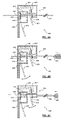
- FIGS. 4A-4C show another embodiment of a delivery device 400 that includes a resheathing/ brake-release trigger 476, with reference to a method of use.
- the delivery device 400 includes a handle 402 with a handle body 404 and an elongate tubular sheath 406 fixedly attached to and extending distally from the handle body 404.
- a pusher member 408 extends slidably through a longitudinal lumen of the sheath 406.
- the handle body 404 is shown in a longitudinal section view that reveals the internal components of the handle 402.
- a first interior portion of the handle 402 includes an advancement member 412 that is biased toward the proximal end of the pusher member 408.
- the advancement member 412 is shown as being biased by a coil spring 415, but other biasing means known in the art may be used.
- the advancement member 412 includes an advancement member aperture 414 through its thickness, through which the pusher member 408 extends.
- a trigger member 416 is pivotably mounted to the handle body 404 and is connected to or otherwise disposed in mechanical communication with the advancement member 412. When the pivot axis 417 is configured as shown, pivoting the lower portion of the trigger member 416 proximally toward the handle body 404 will pivot the upper portion of the trigger member 416 distally, pushing the advancement member 412 distally. When advanced distally by motivation from the trigger member 416, the advancement member 412 engages (in the manner described above with reference to FIGS. 2A-2B ) and pushes distally the pusher member 412.
- a keeper member 422 is mounted to and disposed within a second portion of the handle body 404 and is biased toward its proximal end.
- the keeper member 422 is shown as being proximally biased by a coil spring 425, but other biasing means known in the art may be used.
- the keeper member 422 includes a keeper member aperture 424 through its thickness, through which the pusher member 408 extends.
- a distal portion of the pusher member 408 is attached to an expandable prosthesis such as, for example, a self-expanding stent 445.
- the stent 445 may be constrained by this attachment and/or by the sheath 406.
- the keeper member functions as a "parking brake” or retaining means that will prevent backlash movement due to the pusher member 408 and/or sheath member. This may be needed because, as a stent is deployed distally, the sheath 406 may stretch distally and/ or the pusher 408 may compress, then - when attempting to relax and return to its original length - it may introduce backlash that would drive the pusher 408 proximally if it did't held in place.
- the brake function of the keeper 408 (and of the keeper 108 of FIGS. 1A-1C ) will help to mitigate any such backlash.
- the trigger 476 and components contacting it are not limited in function to braking/ anti-backlash. As will be appreciated with reference to FIGS. 4A-4C , a small degree/distance of actuation will release the braking aspect. In addition, greater actuation (i.e., longer stroke) will move the keeper 422 slidingly along the pusher 408. This will, in turn, build up force in the spring 425, which will - when released - cause the pusher 408 to be moved back proximally in a re-sheathing action (provided that the force provided by the spring is configured to be greater than resistance provided by the stent).
- FIG. 4A shows the device 400 in an unactuated state. Actuation is described with reference to FIG. 4B .
- a user will pivot the lower portion of the trigger 416 toward the handle body 404. This action inclines the advancement member 412 to a first angle where its aperture 414 captures/ engages the pusher member 408 and pushes it forward/ distally.
- the keeper member 422 is disposed at an angle wherein its aperture 424 allows freely sliding distal-ward passage of the pusher member 408 therethrough.
- a stent 445 e.g., into a patient's esophagus
- the stent 445 has been partially deployed such that it has expanded sufficiently to engage patient tissue, it may be difficult or impossible to move the stent longitudinally without injuring the patient and/or damaging the stent if it remains expanded.
- the present device 400 provides for a resheathing function, described with reference to FIG. 4C .
- a user may actuate the keeper member 422 by manually pulling the pusher 408 while operating the second trigger 476 to release the braking function of the keeper 422.
- a user will pivot the resheathing trigger 476 to angle the keeper 422 (e.g., toward vertical) such that it will allow the pusher 408 to move proximally.
- FIG. 4C shows the trigger 476 and keeper 422 back in their default/ 'braking' position with motion arrows indicating the "release motion" of each).
- the longitudinal position of the device 400 (with the sheathed stent 445) may be adjusted as desired, and the stent deployed as described above with reference to FIGS. 4A-4B .
Landscapes
- Health & Medical Sciences (AREA)
- Engineering & Computer Science (AREA)
- Biomedical Technology (AREA)
- Cardiology (AREA)
- Oral & Maxillofacial Surgery (AREA)
- Transplantation (AREA)
- Heart & Thoracic Surgery (AREA)
- Vascular Medicine (AREA)
- Life Sciences & Earth Sciences (AREA)
- Animal Behavior & Ethology (AREA)
- General Health & Medical Sciences (AREA)
- Public Health (AREA)
- Veterinary Medicine (AREA)
- Media Introduction/Drainage Providing Device (AREA)
- Prostheses (AREA)
- Surgical Instruments (AREA)
Claims (12)
- Protheseneinsetzvorrichtung (100) mit gesteuerter Freigabe und Retraktion, umfassend:einen Griff (102),eine rohrförmige Hülse (106), die fest an dem Griff angebracht und sich distal davon erstreckt, undein längliches Schieberglied (108), das sich durch den Griff und durch ein längliches Lumen der Hülse erstreckt,wobei der Griff Folgendes umfasst:einen Griffkörper (104),ein Vorschubglied (112) im Griffkörper undein Auslöserglied (116),das bezüglich des Griffkörpers schwenkbar und in mechanischer Kommunikation mit dem Vorschubglied angeordnet ist,wobei das Vorschubglied eine Vorschubgliedöffnung (114) umfasst, durch die sich das Schieberglied erstreckt, wobei die Vorschubgliedöffnungdazu konfiguriert ist, das Schieberglied in Fangeingriff zu nehmen, wenn das Vorschubglied in einem ersten Winkel bezüglich des Schieberglieds angeordnet ist, was der Schwenkbewegung des Auslösers in der ersten Richtung entspricht, unddazu konfiguriert ist, dass das Schieberglied frei dort hindurchgleiten kann, wenn das Vorschubglied in einem zweiten Winkel bezüglich des Schieberglieds angeordnet ist,dadurch gekennzeichnet, dassdas Vorschubglied zu einem proximalen Vorrichtungsende hin vorgespannt ist,das Auslöserglied dazu konfiguriert ist, das Vorschubglied distal zu bewegen, wenn das Auslöserglied in eine erste Richtung geschwenkt wird,der Griff ferner ein an dem Griffkörper angebrachtes Halteglied (122) umfasst, wobei der Haltegliedkörper ebenfalls zu einem proximalen Vorrichtungsende hin vorgespannt ist, und wobei das Halteglied eine Haltegliedöffnung (124) umfasst, durch die sich das Schieberglied erstreckt, wobei die Haltegliedöffnung dazu konfiguriert ist, das Schieberglied hinreichend in Fangeingriff zu nehmen, um seine Bewegung in einer proximalen Richtung zu verhindern, wenn das Halteglied in einem ersten Winkel bezüglich des Schieberglieds angeordnet ist, und dazu konfiguriert ist, dass das Schieberglied frei proximal dort hindurchgleiten kann, wenn das Halteglied in einem zweiten Winkel bezüglich des Schieberglieds angeordnet ist.
- Vorrichtung nach Anspruch 1, ferner umfassend eine selbstexpandierende Prothese, die entfernbar in einem distalen Abschnitt der Hülse angeordnet und am Schieberglied angebracht ist.
- Vorrichtung nach Anspruch 1, wobei die Hülse und das Schieberglied hinreichend flexibel und länglich sind, um eine Prothesenvorrichtung in den Ernährungskanal eines Patienten einzuführen.
- Vorrichtung nach Anspruch 3, wobei die Hülse und das Schieberglied hinreichend flexibel und länglich sind, um eine Prothesenvorrichtung durch den Mund eines Patienten in die Speiseröhre des Patienten einzuführen.
- Vorrichtung nach Anspruch 1, wobei das längliche Schieberglied mindestens einen proximalen Bereich mit mindestens einem flexiblen Gelenk aufweist.
- Vorrichtung nach Anspruch 5, wobei das mindestens eine flexible Gelenk dazu konfiguriert ist zu gestatten, dass sich der mindestens eine proximale Bereich mit dem mindestens einen flexiblen Gelenk im Griffkörper zusammenrollt.
- Vorrichtung nach Anspruch 5, ferner umfassend ein zweites Auslöserglied, das am Griffkörper angebracht und in mechanischer Kommunikation mit dem Halteglied und dem Schieberglied angeordnet ist.
- Vorrichtung nach Anspruch 7, wobei die mechanische Kommunikation des zweiten Auslöserglieds mit dem Halteglied und dem Schieberglied so konfiguriert ist, dass durch Betätigung des zweiten Auslöserglieds das Halteglied mit dem Schieberglied in Eingriff kommt, um das Schieberglied proximal zu bewegen.
- Vorrichtung nach Anspruch 8, ferner umfassend eine selbstexpandierende Prothese, die entfernbar in einem distalen Abschnitt der Hülse angeordnet und so konfiguriert ist, dass sich die Prothese durch Betätigung des zweiten Auslöserglieds proximal bezüglich der Hülse bewegt.
- Vorrichtung nach Anspruch 1, ferner umfassend ein zweites Auslöserglied, das am Griffkörper angebracht und in mechanischer Kommunikation mit dem Halteglied und dem Schieberglied angeordnet ist.
- Vorrichtung nach Anspruch 10, wobei die mechanische Kommunikation des zweiten Auslöserglieds mit dem Halteglied und dem Schieberglied so konfiguriert ist, dass durch Betätigung des zweiten Auslöserglieds das Halteglied mit dem Schieberglied in Eingriff kommt, um das Schieberglied proximal zu bewegen.
- Vorrichtung nach Anspruch 11, ferner umfassend eine selbstexpandierende Prothese, die entfernbar in einem distalen Abschnitt der Hülse angeordnet und so konfiguriert ist, dass sich die Prothese durch Betätigung des zweiten Auslöserglieds proximal bezüglich der Hülse bewegt.
Applications Claiming Priority (2)
| Application Number | Priority Date | Filing Date | Title |
|---|---|---|---|
| US36918310P | 2010-07-30 | 2010-07-30 | |
| PCT/US2011/045282 WO2012015782A1 (en) | 2010-07-30 | 2011-07-26 | Controlled release and recapture prosthetic deployment device |
Publications (2)
| Publication Number | Publication Date |
|---|---|
| EP2598086A1 EP2598086A1 (de) | 2013-06-05 |
| EP2598086B1 true EP2598086B1 (de) | 2016-09-21 |
Family
ID=44629393
Family Applications (1)
| Application Number | Title | Priority Date | Filing Date |
|---|---|---|---|
| EP11738926.2A Active EP2598086B1 (de) | 2010-07-30 | 2011-07-26 | Protheseneinsetzungssystem mit gesteuerter freisetzung und retraktion |
Country Status (8)
| Country | Link |
|---|---|
| US (1) | US8932342B2 (de) |
| EP (1) | EP2598086B1 (de) |
| JP (1) | JP5597309B2 (de) |
| CN (1) | CN103052365B (de) |
| AU (1) | AU2011282909B2 (de) |
| CA (1) | CA2806234C (de) |
| PL (1) | PL2598086T3 (de) |
| WO (1) | WO2012015782A1 (de) |
Families Citing this family (75)
| Publication number | Priority date | Publication date | Assignee | Title |
|---|---|---|---|---|
| US6866679B2 (en) | 2002-03-12 | 2005-03-15 | Ev3 Inc. | Everting stent and stent delivery system |
| DE102007043830A1 (de) | 2007-09-13 | 2009-04-02 | Lozonschi, Lucian, Madison | Herzklappenstent |
| ES2870080T3 (es) | 2009-12-08 | 2021-10-26 | Avalon Medical Ltd | Dispositivo y sistema para reemplazo de válvula mitral transcatéter |
| GB2488107B (en) * | 2011-02-11 | 2013-03-06 | Cook Medical Technologies Llc | Drive assembly for facilitating deployment of an implantable medical device |
| CA3091387C (en) | 2011-08-11 | 2023-01-03 | Tendyne Holdings, Inc. | Improvements for prosthetic valves and related inventions |
| US9827092B2 (en) | 2011-12-16 | 2017-11-28 | Tendyne Holdings, Inc. | Tethers for prosthetic mitral valve |
| US20130226278A1 (en) | 2012-02-23 | 2013-08-29 | Tyco Healthcare Group Lp | Methods and apparatus for luminal stenting |
| US9072624B2 (en) | 2012-02-23 | 2015-07-07 | Covidien Lp | Luminal stenting |
| US9078659B2 (en) | 2012-04-23 | 2015-07-14 | Covidien Lp | Delivery system with hooks for resheathability |
| US9724222B2 (en) | 2012-07-20 | 2017-08-08 | Covidien Lp | Resheathable stent delivery system |
| WO2014022124A1 (en) | 2012-07-28 | 2014-02-06 | Tendyne Holdings, Inc. | Improved multi-component designs for heart valve retrieval device, sealing structures and stent assembly |
| WO2014021905A1 (en) | 2012-07-30 | 2014-02-06 | Tendyne Holdings, Inc. | Improved delivery systems and methods for transcatheter prosthetic valves |
| EP2769680A1 (de) * | 2013-02-22 | 2014-08-27 | Biotronik AG | Freigabevorrichtung zum Lösen eines medizinischen Implantats von einer Einführvorrichtung sowie Einführvorrichtung mit einer Freigabevorrichtung |
| EP2769681B1 (de) * | 2013-02-22 | 2019-08-21 | Biotronik AG | Freigabevorrichtung zum Lösen eines medizinisches Implantats von einer Einführvorrichtung sowie Einführvorrichtung mit einer Freigabevorrichtung |
| EP2777646B1 (de) | 2013-03-13 | 2017-04-26 | Cook Medical Technologies LLC | Stent-Einführungsvorrichtung mit gesteuerter Freisetzung und Rückgewinnung |
| US9308108B2 (en) * | 2013-03-13 | 2016-04-12 | Cook Medical Technologies Llc | Controlled release and recapture stent-deployment device |
| US10463489B2 (en) | 2013-04-02 | 2019-11-05 | Tendyne Holdings, Inc. | Prosthetic heart valve and systems and methods for delivering the same |
| US11224510B2 (en) | 2013-04-02 | 2022-01-18 | Tendyne Holdings, Inc. | Prosthetic heart valve and systems and methods for delivering the same |
| US10478293B2 (en) | 2013-04-04 | 2019-11-19 | Tendyne Holdings, Inc. | Retrieval and repositioning system for prosthetic heart valve |
| US9610159B2 (en) | 2013-05-30 | 2017-04-04 | Tendyne Holdings, Inc. | Structural members for prosthetic mitral valves |
| EP3666227B1 (de) | 2013-06-14 | 2026-03-18 | Avantec Vascular Corporation | Filter- und wiedergewinnungssysteme für untere hohlvene |
| AU2014302505B2 (en) | 2013-06-25 | 2019-11-28 | Tendyne Holdings, Inc. | Thrombus management and structural compliance features for prosthetic heart valves |
| US10130500B2 (en) | 2013-07-25 | 2018-11-20 | Covidien Lp | Methods and apparatus for luminal stenting |
| JP6465883B2 (ja) | 2013-08-01 | 2019-02-06 | テンダイン ホールディングス,インコーポレイテッド | 心外膜アンカーデバイス及び方法 |
| US9782186B2 (en) | 2013-08-27 | 2017-10-10 | Covidien Lp | Vascular intervention system |
| US9827126B2 (en) | 2013-08-27 | 2017-11-28 | Covidien Lp | Delivery of medical devices |
| WO2015058039A1 (en) | 2013-10-17 | 2015-04-23 | Robert Vidlund | Apparatus and methods for alignment and deployment of intracardiac devices |
| ES2773255T3 (es) | 2013-10-28 | 2020-07-10 | Tendyne Holdings Inc | Válvula cardiaca protésica y sistemas para suministrar la misma |
| US9526611B2 (en) | 2013-10-29 | 2016-12-27 | Tendyne Holdings, Inc. | Apparatus and methods for delivery of transcatheter prosthetic valves |
| WO2015120122A2 (en) | 2014-02-05 | 2015-08-13 | Robert Vidlund | Apparatus and methods for transfemoral delivery of prosthetic mitral valve |
| WO2016112085A2 (en) | 2015-01-07 | 2016-07-14 | Mark Christianson | Prosthetic mitral valves and apparatus and methods for delivery of same |
| WO2016126942A2 (en) | 2015-02-05 | 2016-08-11 | Vidlund Robert M | Expandable epicardial pads and devices and methods for delivery of same |
| US9986993B2 (en) | 2014-02-11 | 2018-06-05 | Tendyne Holdings, Inc. | Adjustable tether and epicardial pad system for prosthetic heart valve |
| GB201402758D0 (en) | 2014-02-17 | 2014-04-02 | Isis Innovation | Stent placement device |
| CN110338911B (zh) | 2014-03-10 | 2022-12-23 | 坦迪尼控股股份有限公司 | 用于定位和监测假体二尖瓣的系绳负荷的装置和方法 |
| US10154920B2 (en) | 2014-11-04 | 2018-12-18 | Abbott Cardiovascular Systems Inc. | Methods and systems for delivering an implant using a planetary gear actuation assembly |
| US10639181B2 (en) | 2014-11-04 | 2020-05-05 | Abbott Cardiovascular Systems Inc. | Methods and systems for delivering an implant |
| WO2016094676A1 (en) | 2014-12-12 | 2016-06-16 | Avantec Vascular Corporation | Ivc filter retrieval systems with interposed support members |
| US10278804B2 (en) * | 2014-12-12 | 2019-05-07 | Avantec Vascular Corporation | IVC filter retrieval systems with releasable capture feature |
| US9192500B1 (en) * | 2015-01-29 | 2015-11-24 | Intact Vascular, Inc. | Delivery device and method of delivery |
| EP3283010B1 (de) | 2015-04-16 | 2020-06-17 | Tendyne Holdings, Inc. | Vorrichtung zur freisetzung und neupositionierung von transkatheter-klappenprothesen |
| CN105147425B (zh) * | 2015-07-31 | 2017-07-11 | 哈尔滨医科大学 | 一种短外鞘管上消化道支架推送系统 |
| US10327894B2 (en) | 2015-09-18 | 2019-06-25 | Tendyne Holdings, Inc. | Methods for delivery of prosthetic mitral valves |
| WO2017096157A1 (en) | 2015-12-03 | 2017-06-08 | Tendyne Holdings, Inc. | Frame features for prosthetic mitral valves |
| CA3006010C (en) | 2015-12-28 | 2023-09-26 | Tendyne Holdings, Inc. | Atrial pocket closures for prosthetic heart valves |
| US10470877B2 (en) | 2016-05-03 | 2019-11-12 | Tendyne Holdings, Inc. | Apparatus and methods for anterior valve leaflet management |
| US11039921B2 (en) | 2016-06-13 | 2021-06-22 | Tendyne Holdings, Inc. | Sequential delivery of two-part prosthetic mitral valve |
| WO2018005779A1 (en) | 2016-06-30 | 2018-01-04 | Tegels Zachary J | Prosthetic heart valves and apparatus and methods for delivery of same |
| US11065116B2 (en) | 2016-07-12 | 2021-07-20 | Tendyne Holdings, Inc. | Apparatus and methods for trans-septal retrieval of prosthetic heart valves |
| CN110167482A (zh) | 2016-12-22 | 2019-08-23 | 阿万泰血管公司 | 具有系绳的用于取回系统的系统、装置和方法 |
| US10376396B2 (en) | 2017-01-19 | 2019-08-13 | Covidien Lp | Coupling units for medical device delivery systems |
| JP7216066B2 (ja) | 2017-07-13 | 2023-01-31 | テンダイン ホールディングス,インコーポレイテッド | 人工心臓弁とその送達のための装置および方法 |
| US11191639B2 (en) | 2017-08-28 | 2021-12-07 | Tendyne Holdings, Inc. | Prosthetic heart valves with tether coupling features |
| US11413176B2 (en) | 2018-04-12 | 2022-08-16 | Covidien Lp | Medical device delivery |
| US11071637B2 (en) | 2018-04-12 | 2021-07-27 | Covidien Lp | Medical device delivery |
| US10786377B2 (en) | 2018-04-12 | 2020-09-29 | Covidien Lp | Medical device delivery |
| US11123209B2 (en) | 2018-04-12 | 2021-09-21 | Covidien Lp | Medical device delivery |
| US10441449B1 (en) | 2018-05-30 | 2019-10-15 | Vesper Medical, Inc. | Rotary handle stent delivery system and method |
| CN112584799A (zh) | 2018-06-29 | 2021-03-30 | 阿万泰血管公司 | 用于移植物和部署装置的系统和方法 |
| US10813780B2 (en) * | 2018-08-08 | 2020-10-27 | DePuy Synthes Products, Inc. | Intraluminal implant delivery system and method |
| US10449073B1 (en) | 2018-09-18 | 2019-10-22 | Vesper Medical, Inc. | Rotary handle stent delivery system and method |
| US11273285B2 (en) * | 2019-02-07 | 2022-03-15 | DePuy Synthes Products, Inc. | Ancillary device for detaching implants |
| USD959659S1 (en) | 2019-05-10 | 2022-08-02 | DePuy Synthes Products, Inc. | Implant release handle |
| US11413174B2 (en) | 2019-06-26 | 2022-08-16 | Covidien Lp | Core assembly for medical device delivery systems |
| US11648110B2 (en) | 2019-12-05 | 2023-05-16 | Tendyne Holdings, Inc. | Braided anchor for mitral valve |
| US11648114B2 (en) | 2019-12-20 | 2023-05-16 | Tendyne Holdings, Inc. | Distally loaded sheath and loading funnel |
| US11951002B2 (en) | 2020-03-30 | 2024-04-09 | Tendyne Holdings, Inc. | Apparatus and methods for valve and tether fixation |
| US11219541B2 (en) | 2020-05-21 | 2022-01-11 | Vesper Medical, Inc. | Wheel lock for thumbwheel actuated device |
| US11678980B2 (en) | 2020-08-19 | 2023-06-20 | Tendyne Holdings, Inc. | Fully-transseptal apical pad with pulley for tensioning |
| CN111811721B (zh) * | 2020-09-01 | 2021-01-12 | 上海介入医疗器械有限公司 | 一种柔性杆推送阻力检测系统以及方法 |
| US12458518B2 (en) | 2021-02-17 | 2025-11-04 | Covidien Lp | Medical device delivery devices, systems, and methods |
| US12042413B2 (en) | 2021-04-07 | 2024-07-23 | Covidien Lp | Delivery of medical devices |
| US12109137B2 (en) | 2021-07-30 | 2024-10-08 | Covidien Lp | Medical device delivery |
| US11944558B2 (en) | 2021-08-05 | 2024-04-02 | Covidien Lp | Medical device delivery devices, systems, and methods |
| JP7749135B2 (ja) * | 2022-07-28 | 2025-10-03 | オリンパスメディカルシステムズ株式会社 | デリバリーデバイス |
Family Cites Families (99)
| Publication number | Priority date | Publication date | Assignee | Title |
|---|---|---|---|---|
| US1724983A (en) | 1927-03-31 | 1929-08-20 | Carl W Weiss | Roller-clutch bearing |
| US3132549A (en) | 1961-08-29 | 1964-05-12 | Alvin W Lee | Hand wrench |
| US3897786A (en) | 1971-02-05 | 1975-08-05 | Richards Mfg Co | Disposable myringotomy apparatus |
| US3888258A (en) | 1972-11-07 | 1975-06-10 | Taichiro Akiyama | Drain for the eardrum and apparatus for introducing the same |
| US5693083A (en) | 1983-12-09 | 1997-12-02 | Endovascular Technologies, Inc. | Thoracic graft and delivery catheter |
| US4559041A (en) | 1984-06-25 | 1985-12-17 | Razi M Dean | Cannula introducers |
| US4921484A (en) | 1988-07-25 | 1990-05-01 | Cordis Corporation | Mesh balloon catheter device |
| US5591172A (en) | 1991-06-14 | 1997-01-07 | Ams Medinvent S.A. | Transluminal implantation device |
| EP0536610B1 (de) | 1991-10-11 | 1997-09-03 | Angiomed GmbH & Co. Medizintechnik KG | Vorrichtung zum Aufweiten einer Stenose |
| US5275151A (en) | 1991-12-11 | 1994-01-04 | Clarus Medical Systems, Inc. | Handle for deflectable catheter |
| US5707376A (en) | 1992-08-06 | 1998-01-13 | William Cook Europe A/S | Stent introducer and method of use |
| EP0676936A1 (de) | 1992-12-30 | 1995-10-18 | Schneider (Usa) Inc. | Vorrichtungzur freigebung eines implantierbaren stents |
| US5458615A (en) | 1993-07-06 | 1995-10-17 | Advanced Cardiovascular Systems, Inc. | Stent delivery system |
| ES2135520T3 (es) | 1993-11-04 | 1999-11-01 | Bard Inc C R | Protesis vascular no migrante. |
| US5443477A (en) | 1994-02-10 | 1995-08-22 | Stentco, Inc. | Apparatus and method for deployment of radially expandable stents by a mechanical linkage |
| US6039749A (en) | 1994-02-10 | 2000-03-21 | Endovascular Systems, Inc. | Method and apparatus for deploying non-circular stents and graftstent complexes |
| WO1995023008A1 (en) * | 1994-02-28 | 1995-08-31 | Querals & Fine, Inc. | Insertion tool for an intraluminal graft procedure having locking features |
| US5415664A (en) * | 1994-03-30 | 1995-05-16 | Corvita Corporation | Method and apparatus for introducing a stent or a stent-graft |
| US5683451A (en) | 1994-06-08 | 1997-11-04 | Cardiovascular Concepts, Inc. | Apparatus and methods for deployment release of intraluminal prostheses |
| JPH10503411A (ja) | 1995-05-25 | 1998-03-31 | メドトロニック・インコーポレーテッド | ステントアッセンブリ及びその使用方法 |
| US5700269A (en) | 1995-06-06 | 1997-12-23 | Corvita Corporation | Endoluminal prosthesis deployment device for use with prostheses of variable length and having retraction ability |
| US5702418A (en) | 1995-09-12 | 1997-12-30 | Boston Scientific Corporation | Stent delivery system |
| DK0775470T3 (da) | 1995-11-14 | 1999-10-18 | Schneider Europ Gmbh | Stenindsætningsapparat |
| US6629981B2 (en) | 2000-07-06 | 2003-10-07 | Endocare, Inc. | Stent delivery system |
| US6413269B1 (en) | 2000-07-06 | 2002-07-02 | Endocare, Inc. | Stent delivery system |
| US5681323A (en) | 1996-07-15 | 1997-10-28 | Arick; Daniel S. | Emergency cricothyrotomy tube insertion |
| US6254628B1 (en) | 1996-12-09 | 2001-07-03 | Micro Therapeutics, Inc. | Intracranial stent |
| DE69726317T2 (de) * | 1996-09-18 | 2004-09-16 | Micro Therapeutics, Inc., Irvine | Intrakranialer stent |
| US5968052A (en) | 1996-11-27 | 1999-10-19 | Scimed Life Systems Inc. | Pull back stent delivery system with pistol grip retraction handle |
| US5776142A (en) | 1996-12-19 | 1998-07-07 | Medtronic, Inc. | Controllable stent delivery system and method |
| US5906619A (en) | 1997-07-24 | 1999-05-25 | Medtronic, Inc. | Disposable delivery device for endoluminal prostheses |
| US8075570B2 (en) | 2001-11-28 | 2011-12-13 | Aptus Endosystems, Inc. | Intraluminal prosthesis attachment systems and methods |
| US5993460A (en) | 1998-03-27 | 1999-11-30 | Advanced Cardiovascular Systems, Inc. | Rapid exchange delivery system for stenting a body lumen |
| US6520983B1 (en) | 1998-03-31 | 2003-02-18 | Scimed Life Systems, Inc. | Stent delivery system |
| US6143021A (en) | 1998-07-10 | 2000-11-07 | American Medical Systems, Inc. | Stent placement instrument and method of assembly |
| US5944727A (en) * | 1998-09-02 | 1999-08-31 | Datascope Investment Corp. | Stent/graft catheter handle |
| US6162231A (en) | 1998-09-14 | 2000-12-19 | Endocare, Inc. | Stent insertion device |
| US6093194A (en) | 1998-09-14 | 2000-07-25 | Endocare, Inc. | Insertion device for stents and methods for use |
| CA2345686C (en) | 1998-09-30 | 2008-08-12 | Bard Peripheral Vascular, Inc. | Delivery mechanism for implantable stent |
| US7578828B2 (en) * | 1999-01-15 | 2009-08-25 | Medtronic, Inc. | Methods and devices for placing a conduit in fluid communication with a target vessel |
| US6146415A (en) | 1999-05-07 | 2000-11-14 | Advanced Cardiovascular Systems, Inc. | Stent delivery system |
| US6375676B1 (en) | 1999-05-17 | 2002-04-23 | Advanced Cardiovascular Systems, Inc. | Self-expanding stent with enhanced delivery precision and stent delivery system |
| US6858034B1 (en) | 1999-05-20 | 2005-02-22 | Scimed Life Systems, Inc. | Stent delivery system for prevention of kinking, and method of loading and using same |
| FR2797761B1 (fr) | 1999-08-24 | 2002-03-22 | Novatech Inc | Dispositif pour provoquer le largage dans un conduit humain ou animal d'un objet, en particulier une prothese, et systeme d'implantation comportant un catheter et un tel dispositif |
| US7169187B2 (en) | 1999-12-22 | 2007-01-30 | Ethicon, Inc. | Biodegradable stent |
| US6344044B1 (en) | 2000-02-11 | 2002-02-05 | Edwards Lifesciences Corp. | Apparatus and methods for delivery of intraluminal prosthesis |
| US6942688B2 (en) | 2000-02-29 | 2005-09-13 | Cordis Corporation | Stent delivery system having delivery catheter member with a clear transition zone |
| US6391050B1 (en) | 2000-02-29 | 2002-05-21 | Scimed Life Systems, Inc. | Self-expanding stent delivery system |
| JP4940390B2 (ja) | 2000-07-14 | 2012-05-30 | クック メディカル テクノロジーズ エルエルシー | 編構造体およびコイルを有する医療装置 |
| US6786918B1 (en) | 2000-10-17 | 2004-09-07 | Medtronic Vascular, Inc. | Stent delivery system |
| US6428566B1 (en) | 2000-10-31 | 2002-08-06 | Advanced Cardiovascular Systems, Inc. | Flexible hoop and link sheath for a stent delivery system |
| US20020095203A1 (en) | 2001-01-18 | 2002-07-18 | Intra Therapeutics, Inc. | Catheter system with spacer member |
| US6749627B2 (en) | 2001-01-18 | 2004-06-15 | Ev3 Peripheral, Inc. | Grip for stent delivery system |
| US6592549B2 (en) | 2001-03-14 | 2003-07-15 | Scimed Life Systems, Inc. | Rapid exchange stent delivery system and associated components |
| US20050021123A1 (en) | 2001-04-30 | 2005-01-27 | Jurgen Dorn | Variable speed self-expanding stent delivery system and luer locking connector |
| GB0110551D0 (en) * | 2001-04-30 | 2001-06-20 | Angiomed Ag | Self-expanding stent delivery service |
| GB0114939D0 (en) | 2001-06-19 | 2001-08-08 | Angiomed Ag | Luer connector portion |
| US6926732B2 (en) | 2001-06-01 | 2005-08-09 | Ams Research Corporation | Stent delivery device and method |
| US6599296B1 (en) | 2001-07-27 | 2003-07-29 | Advanced Cardiovascular Systems, Inc. | Ratcheting handle for intraluminal catheter systems |
| US6755854B2 (en) | 2001-07-31 | 2004-06-29 | Advanced Cardiovascular Systems, Inc. | Control device and mechanism for deploying a self-expanding medical device |
| US6866669B2 (en) | 2001-10-12 | 2005-03-15 | Cordis Corporation | Locking handle deployment mechanism for medical device and method |
| US6939352B2 (en) | 2001-10-12 | 2005-09-06 | Cordis Corporation | Handle deployment mechanism for medical device and method |
| US20030093084A1 (en) | 2001-11-13 | 2003-05-15 | Optonol Ltd. | Delivery devices for flow regulating implants |
| US7147657B2 (en) | 2003-10-23 | 2006-12-12 | Aptus Endosystems, Inc. | Prosthesis delivery systems and methods |
| US6991646B2 (en) | 2001-12-18 | 2006-01-31 | Linvatec Biomaterials, Inc. | Method and apparatus for delivering a stent into a body lumen |
| US6911039B2 (en) | 2002-04-23 | 2005-06-28 | Medtronic Vascular, Inc. | Integrated mechanical handle with quick slide mechanism |
| US20030225445A1 (en) | 2002-05-14 | 2003-12-04 | Derus Patricia M. | Surgical stent delivery devices and methods |
| EP1513472B1 (de) | 2002-05-31 | 2015-12-09 | Cook Medical Technologies LLC | Gerät zur einführung eines stents |
| US20040006380A1 (en) | 2002-07-05 | 2004-01-08 | Buck Jerrick C. | Stent delivery system |
| US9655753B2 (en) | 2002-09-30 | 2017-05-23 | Board Of Regents, The University Of Texas System | Stent delivery system and method of use |
| US6673101B1 (en) | 2002-10-09 | 2004-01-06 | Endovascular Technologies, Inc. | Apparatus and method for deploying self-expanding stents |
| US7753945B2 (en) | 2003-01-17 | 2010-07-13 | Gore Enterprise Holdings, Inc. | Deployment system for an endoluminal device |
| US20040215229A1 (en) | 2003-04-22 | 2004-10-28 | Medtronic Ave, Inc. | Stent delivery system and method |
| US7604660B2 (en) | 2003-05-01 | 2009-10-20 | Merit Medical Systems, Inc. | Bifurcated medical appliance delivery apparatus and method |
| RU2238043C1 (ru) | 2003-06-30 | 2004-10-20 | Шкарубо Алексей Николаевич | Устройство для установки медицинских инструментов |
| WO2005013855A2 (en) | 2003-08-01 | 2005-02-17 | Cook Urological, Incorporated | Implant delivery device |
| DE602004018665D1 (de) | 2003-09-02 | 2009-02-05 | Abbott Lab | Einführsystem für ein medizinisches Gerät |
| US7993384B2 (en) | 2003-09-12 | 2011-08-09 | Abbott Cardiovascular Systems Inc. | Delivery system for medical devices |
| US7758625B2 (en) | 2003-09-12 | 2010-07-20 | Abbott Vascular Solutions Inc. | Delivery system for medical devices |
| US7967829B2 (en) | 2003-10-09 | 2011-06-28 | Boston Scientific Scimed, Inc. | Medical device delivery system |
| US7867271B2 (en) | 2003-11-20 | 2011-01-11 | Advanced Cardiovascular Systems, Inc. | Rapid-exchange delivery systems for self-expanding stents |
| US7326236B2 (en) | 2003-12-23 | 2008-02-05 | Xtent, Inc. | Devices and methods for controlling and indicating the length of an interventional element |
| US20050209670A1 (en) | 2004-03-02 | 2005-09-22 | Cardiomind, Inc. | Stent delivery system with diameter adaptive restraint |
| US20050209685A1 (en) | 2004-03-17 | 2005-09-22 | Shifrin Edward G | Graft delivery and anchoring system |
| US7285130B2 (en) | 2004-04-27 | 2007-10-23 | Boston Scientific Scimed, Inc. | Stent delivery system |
| US20050256562A1 (en) | 2004-05-14 | 2005-11-17 | Boston Scientific Scimed, Inc. | Stent delivery handle and assembly formed therewith |
| EP1746940A2 (de) * | 2004-05-17 | 2007-01-31 | Datascope Investment Corp. | Chirurgisches klammersystem |
| US20050273151A1 (en) | 2004-06-04 | 2005-12-08 | John Fulkerson | Stent delivery system |
| US20050288766A1 (en) | 2004-06-28 | 2005-12-29 | Xtent, Inc. | Devices and methods for controlling expandable prostheses during deployment |
| EP1768618B1 (de) * | 2004-07-09 | 2011-04-20 | GI Dynamics, Inc. | Vorrichtungen für die platzierung einer gastrotintestinalen hülse |
| WO2007005799A1 (en) | 2005-06-30 | 2007-01-11 | Abbott Laboratories | Delivery system for a medical device |
| CN1911188B (zh) * | 2005-08-09 | 2010-10-13 | 微创医疗器械(上海)有限公司 | 术中支架假体以及输送器 |
| US7935141B2 (en) | 2005-08-17 | 2011-05-03 | C. R. Bard, Inc. | Variable speed stent delivery system |
| IL170698A (en) * | 2005-09-06 | 2011-11-30 | Allium Ltd | System for delivering a medical device to a body location |
| US20080082158A1 (en) | 2006-09-28 | 2008-04-03 | Cook Incorporated | Method for Deployment of a Stent Graft |
| US9149379B2 (en) | 2007-07-16 | 2015-10-06 | Cook Medical Technologies Llc | Delivery device |
| FR2924917B1 (fr) * | 2007-12-13 | 2011-02-11 | Microval | Appareil de pose de spires de suture resultant d'un fil metallique a memoire de forme. |
| BRPI0916100A2 (pt) * | 2008-11-18 | 2015-11-03 | Robert Laduca | "aparelho para assentar um segundo dispositivo intraluminal para fixação a um primeiro dispositivo intraluminal dentro de uma vasculatura, método de utilização do aparelho, aparelho para assentar um segundo dispositivo intraluminal para ser fixado a um primeiro dispositivo intraluminal dentro de uma vasculatura utilizando o controle de deflexão composto e método de uso do aparelho" |
| EP2391309B1 (de) | 2008-12-30 | 2018-04-04 | Cook Medical Technologies LLC | Abgabevorrichtung |
-
2011
- 2011-07-26 EP EP11738926.2A patent/EP2598086B1/de active Active
- 2011-07-26 JP JP2013523193A patent/JP5597309B2/ja active Active
- 2011-07-26 PL PL11738926T patent/PL2598086T3/pl unknown
- 2011-07-26 AU AU2011282909A patent/AU2011282909B2/en active Active
- 2011-07-26 WO PCT/US2011/045282 patent/WO2012015782A1/en not_active Ceased
- 2011-07-26 CA CA2806234A patent/CA2806234C/en active Active
- 2011-07-26 CN CN201180037152.3A patent/CN103052365B/zh active Active
- 2011-07-27 US US13/192,130 patent/US8932342B2/en active Active
Also Published As
| Publication number | Publication date |
|---|---|
| WO2012015782A1 (en) | 2012-02-02 |
| CN103052365A (zh) | 2013-04-17 |
| US20120029607A1 (en) | 2012-02-02 |
| PL2598086T3 (pl) | 2017-06-30 |
| CN103052365B (zh) | 2015-12-02 |
| JP5597309B2 (ja) | 2014-10-01 |
| US8932342B2 (en) | 2015-01-13 |
| JP2013535286A (ja) | 2013-09-12 |
| AU2011282909B2 (en) | 2013-09-12 |
| CA2806234C (en) | 2015-03-24 |
| AU2011282909A1 (en) | 2013-02-14 |
| CA2806234A1 (en) | 2012-02-02 |
| EP2598086A1 (de) | 2013-06-05 |
Similar Documents
| Publication | Publication Date | Title |
|---|---|---|
| EP2598086B1 (de) | Protheseneinsetzungssystem mit gesteuerter freisetzung und retraktion | |
| US9308108B2 (en) | Controlled release and recapture stent-deployment device | |
| CN205729576U (zh) | 具有近侧限位器和在近侧限位器远侧的环状锁的可再约束支架输送系统 | |
| EP1380271B1 (de) | Einführbesteck mit Sperrgriff für medizinisches Gerät | |
| US5702418A (en) | Stent delivery system | |
| AU2011293898B2 (en) | Staged deployment devices and methods for transcatheter heart valve delivery systems | |
| EP3028680B1 (de) | Griffanordnung einer ausgabevorrichtung zum sequentiellen einsetzen einer prothese | |
| EP2490629B1 (de) | Rotationsgesteuerte expansionsvorrichtung | |
| US20130035636A1 (en) | Delivery and Deployment Catheter for an Implantable Medical Device | |
| EP1701675B1 (de) | Griff für ein implantatablagesystem und anwendungsverfahren | |
| US20120172963A1 (en) | Delivery device | |
| JP2017510308A (ja) | 送入装置および送入方法 | |
| WO2011017189A1 (en) | Roll sleeve mechanism for proximal release stent delivery device | |
| IL170698A (en) | System for delivering a medical device to a body location | |
| CN105392452A (zh) | 用于部分不受约束的内假体的传送装置 | |
| CN111526803B (zh) | 用于部署血管植入装置的互锁环联接/脱离系统 | |
| EP2777646B1 (de) | Stent-Einführungsvorrichtung mit gesteuerter Freisetzung und Rückgewinnung | |
| CN121358439A (zh) | 用于部署可扩张植入物的器械和方法 | |
| EP3179964B1 (de) | Griff für den einsatz einer medizinischen vorrichtung | |
| CN115607238A (zh) | 多用途手柄及包括其的医疗圈套器或其他装置 |
Legal Events
| Date | Code | Title | Description |
|---|---|---|---|
| PUAI | Public reference made under article 153(3) epc to a published international application that has entered the european phase |
Free format text: ORIGINAL CODE: 0009012 |
|
| 17P | Request for examination filed |
Effective date: 20130131 |
|
| AK | Designated contracting states |
Kind code of ref document: A1 Designated state(s): AL AT BE BG CH CY CZ DE DK EE ES FI FR GB GR HR HU IE IS IT LI LT LU LV MC MK MT NL NO PL PT RO RS SE SI SK SM TR |
|
| DAX | Request for extension of the european patent (deleted) | ||
| REG | Reference to a national code |
Ref country code: DE Ref legal event code: R079 Ref document number: 602011030557 Country of ref document: DE Free format text: PREVIOUS MAIN CLASS: A61F0002840000 Ipc: A61F0002966000 |
|
| GRAP | Despatch of communication of intention to grant a patent |
Free format text: ORIGINAL CODE: EPIDOSNIGR1 |
|
| RIC1 | Information provided on ipc code assigned before grant |
Ipc: A61F 2/966 20130101AFI20160609BHEP |
|
| INTG | Intention to grant announced |
Effective date: 20160701 |
|
| RAP1 | Party data changed (applicant data changed or rights of an application transferred) |
Owner name: COOK MEDICAL TECHNOLOGIES LLC |
|
| GRAS | Grant fee paid |
Free format text: ORIGINAL CODE: EPIDOSNIGR3 |
|
| GRAA | (expected) grant |
Free format text: ORIGINAL CODE: 0009210 |
|
| AK | Designated contracting states |
Kind code of ref document: B1 Designated state(s): AL AT BE BG CH CY CZ DE DK EE ES FI FR GB GR HR HU IE IS IT LI LT LU LV MC MK MT NL NO PL PT RO RS SE SI SK SM TR |
|
| REG | Reference to a national code |
Ref country code: GB Ref legal event code: FG4D |
|
| REG | Reference to a national code |
Ref country code: CH Ref legal event code: EP |
|
| REG | Reference to a national code |
Ref country code: AT Ref legal event code: REF Ref document number: 830431 Country of ref document: AT Kind code of ref document: T Effective date: 20161015 |
|
| REG | Reference to a national code |
Ref country code: IE Ref legal event code: FG4D |
|
| REG | Reference to a national code |
Ref country code: DE Ref legal event code: R096 Ref document number: 602011030557 Country of ref document: DE |
|
| REG | Reference to a national code |
Ref country code: LT Ref legal event code: MG4D Ref country code: NL Ref legal event code: MP Effective date: 20160921 |
|
| PG25 | Lapsed in a contracting state [announced via postgrant information from national office to epo] |
Ref country code: RS Free format text: LAPSE BECAUSE OF FAILURE TO SUBMIT A TRANSLATION OF THE DESCRIPTION OR TO PAY THE FEE WITHIN THE PRESCRIBED TIME-LIMIT Effective date: 20160921 Ref country code: NO Free format text: LAPSE BECAUSE OF FAILURE TO SUBMIT A TRANSLATION OF THE DESCRIPTION OR TO PAY THE FEE WITHIN THE PRESCRIBED TIME-LIMIT Effective date: 20161221 Ref country code: LT Free format text: LAPSE BECAUSE OF FAILURE TO SUBMIT A TRANSLATION OF THE DESCRIPTION OR TO PAY THE FEE WITHIN THE PRESCRIBED TIME-LIMIT Effective date: 20160921 Ref country code: FI Free format text: LAPSE BECAUSE OF FAILURE TO SUBMIT A TRANSLATION OF THE DESCRIPTION OR TO PAY THE FEE WITHIN THE PRESCRIBED TIME-LIMIT Effective date: 20160921 |
|
| REG | Reference to a national code |
Ref country code: AT Ref legal event code: MK05 Ref document number: 830431 Country of ref document: AT Kind code of ref document: T Effective date: 20160921 |
|
| PG25 | Lapsed in a contracting state [announced via postgrant information from national office to epo] |
Ref country code: LV Free format text: LAPSE BECAUSE OF FAILURE TO SUBMIT A TRANSLATION OF THE DESCRIPTION OR TO PAY THE FEE WITHIN THE PRESCRIBED TIME-LIMIT Effective date: 20160921 Ref country code: SE Free format text: LAPSE BECAUSE OF FAILURE TO SUBMIT A TRANSLATION OF THE DESCRIPTION OR TO PAY THE FEE WITHIN THE PRESCRIBED TIME-LIMIT Effective date: 20160921 Ref country code: GR Free format text: LAPSE BECAUSE OF FAILURE TO SUBMIT A TRANSLATION OF THE DESCRIPTION OR TO PAY THE FEE WITHIN THE PRESCRIBED TIME-LIMIT Effective date: 20161222 Ref country code: NL Free format text: LAPSE BECAUSE OF FAILURE TO SUBMIT A TRANSLATION OF THE DESCRIPTION OR TO PAY THE FEE WITHIN THE PRESCRIBED TIME-LIMIT Effective date: 20160921 |
|
| PG25 | Lapsed in a contracting state [announced via postgrant information from national office to epo] |
Ref country code: EE Free format text: LAPSE BECAUSE OF FAILURE TO SUBMIT A TRANSLATION OF THE DESCRIPTION OR TO PAY THE FEE WITHIN THE PRESCRIBED TIME-LIMIT Effective date: 20160921 Ref country code: RO Free format text: LAPSE BECAUSE OF FAILURE TO SUBMIT A TRANSLATION OF THE DESCRIPTION OR TO PAY THE FEE WITHIN THE PRESCRIBED TIME-LIMIT Effective date: 20160921 |
|
| PG25 | Lapsed in a contracting state [announced via postgrant information from national office to epo] |
Ref country code: PT Free format text: LAPSE BECAUSE OF FAILURE TO SUBMIT A TRANSLATION OF THE DESCRIPTION OR TO PAY THE FEE WITHIN THE PRESCRIBED TIME-LIMIT Effective date: 20170123 Ref country code: ES Free format text: LAPSE BECAUSE OF FAILURE TO SUBMIT A TRANSLATION OF THE DESCRIPTION OR TO PAY THE FEE WITHIN THE PRESCRIBED TIME-LIMIT Effective date: 20160921 Ref country code: BE Free format text: LAPSE BECAUSE OF FAILURE TO SUBMIT A TRANSLATION OF THE DESCRIPTION OR TO PAY THE FEE WITHIN THE PRESCRIBED TIME-LIMIT Effective date: 20160921 Ref country code: BG Free format text: LAPSE BECAUSE OF FAILURE TO SUBMIT A TRANSLATION OF THE DESCRIPTION OR TO PAY THE FEE WITHIN THE PRESCRIBED TIME-LIMIT Effective date: 20161221 Ref country code: SK Free format text: LAPSE BECAUSE OF FAILURE TO SUBMIT A TRANSLATION OF THE DESCRIPTION OR TO PAY THE FEE WITHIN THE PRESCRIBED TIME-LIMIT Effective date: 20160921 Ref country code: SM Free format text: LAPSE BECAUSE OF FAILURE TO SUBMIT A TRANSLATION OF THE DESCRIPTION OR TO PAY THE FEE WITHIN THE PRESCRIBED TIME-LIMIT Effective date: 20160921 Ref country code: AT Free format text: LAPSE BECAUSE OF FAILURE TO SUBMIT A TRANSLATION OF THE DESCRIPTION OR TO PAY THE FEE WITHIN THE PRESCRIBED TIME-LIMIT Effective date: 20160921 Ref country code: CZ Free format text: LAPSE BECAUSE OF FAILURE TO SUBMIT A TRANSLATION OF THE DESCRIPTION OR TO PAY THE FEE WITHIN THE PRESCRIBED TIME-LIMIT Effective date: 20160921 Ref country code: IS Free format text: LAPSE BECAUSE OF FAILURE TO SUBMIT A TRANSLATION OF THE DESCRIPTION OR TO PAY THE FEE WITHIN THE PRESCRIBED TIME-LIMIT Effective date: 20170121 |
|
| REG | Reference to a national code |
Ref country code: DE Ref legal event code: R097 Ref document number: 602011030557 Country of ref document: DE |
|
| PG25 | Lapsed in a contracting state [announced via postgrant information from national office to epo] |
Ref country code: IT Free format text: LAPSE BECAUSE OF FAILURE TO SUBMIT A TRANSLATION OF THE DESCRIPTION OR TO PAY THE FEE WITHIN THE PRESCRIBED TIME-LIMIT Effective date: 20160921 |
|
| PLBE | No opposition filed within time limit |
Free format text: ORIGINAL CODE: 0009261 |
|
| STAA | Information on the status of an ep patent application or granted ep patent |
Free format text: STATUS: NO OPPOSITION FILED WITHIN TIME LIMIT |
|
| PG25 | Lapsed in a contracting state [announced via postgrant information from national office to epo] |
Ref country code: DK Free format text: LAPSE BECAUSE OF FAILURE TO SUBMIT A TRANSLATION OF THE DESCRIPTION OR TO PAY THE FEE WITHIN THE PRESCRIBED TIME-LIMIT Effective date: 20160921 |
|
| 26N | No opposition filed |
Effective date: 20170622 |
|
| PG25 | Lapsed in a contracting state [announced via postgrant information from national office to epo] |
Ref country code: SI Free format text: LAPSE BECAUSE OF FAILURE TO SUBMIT A TRANSLATION OF THE DESCRIPTION OR TO PAY THE FEE WITHIN THE PRESCRIBED TIME-LIMIT Effective date: 20160921 |
|
| REG | Reference to a national code |
Ref country code: CH Ref legal event code: PL |
|
| REG | Reference to a national code |
Ref country code: FR Ref legal event code: ST Effective date: 20180330 |
|
| PG25 | Lapsed in a contracting state [announced via postgrant information from national office to epo] |
Ref country code: CH Free format text: LAPSE BECAUSE OF NON-PAYMENT OF DUE FEES Effective date: 20170731 Ref country code: LI Free format text: LAPSE BECAUSE OF NON-PAYMENT OF DUE FEES Effective date: 20170731 |
|
| PG25 | Lapsed in a contracting state [announced via postgrant information from national office to epo] |
Ref country code: FR Free format text: LAPSE BECAUSE OF NON-PAYMENT OF DUE FEES Effective date: 20170731 |
|
| PG25 | Lapsed in a contracting state [announced via postgrant information from national office to epo] |
Ref country code: LU Free format text: LAPSE BECAUSE OF NON-PAYMENT OF DUE FEES Effective date: 20170726 |
|
| PG25 | Lapsed in a contracting state [announced via postgrant information from national office to epo] |
Ref country code: MT Free format text: LAPSE BECAUSE OF NON-PAYMENT OF DUE FEES Effective date: 20170726 |
|
| PG25 | Lapsed in a contracting state [announced via postgrant information from national office to epo] |
Ref country code: AL Free format text: LAPSE BECAUSE OF FAILURE TO SUBMIT A TRANSLATION OF THE DESCRIPTION OR TO PAY THE FEE WITHIN THE PRESCRIBED TIME-LIMIT Effective date: 20160921 |
|
| PG25 | Lapsed in a contracting state [announced via postgrant information from national office to epo] |
Ref country code: HU Free format text: LAPSE BECAUSE OF FAILURE TO SUBMIT A TRANSLATION OF THE DESCRIPTION OR TO PAY THE FEE WITHIN THE PRESCRIBED TIME-LIMIT; INVALID AB INITIO Effective date: 20110726 Ref country code: MC Free format text: LAPSE BECAUSE OF FAILURE TO SUBMIT A TRANSLATION OF THE DESCRIPTION OR TO PAY THE FEE WITHIN THE PRESCRIBED TIME-LIMIT Effective date: 20160921 |
|
| PG25 | Lapsed in a contracting state [announced via postgrant information from national office to epo] |
Ref country code: CY Free format text: LAPSE BECAUSE OF NON-PAYMENT OF DUE FEES Effective date: 20160921 |
|
| PG25 | Lapsed in a contracting state [announced via postgrant information from national office to epo] |
Ref country code: MK Free format text: LAPSE BECAUSE OF FAILURE TO SUBMIT A TRANSLATION OF THE DESCRIPTION OR TO PAY THE FEE WITHIN THE PRESCRIBED TIME-LIMIT Effective date: 20160921 |
|
| PG25 | Lapsed in a contracting state [announced via postgrant information from national office to epo] |
Ref country code: TR Free format text: LAPSE BECAUSE OF FAILURE TO SUBMIT A TRANSLATION OF THE DESCRIPTION OR TO PAY THE FEE WITHIN THE PRESCRIBED TIME-LIMIT Effective date: 20160921 |
|
| PG25 | Lapsed in a contracting state [announced via postgrant information from national office to epo] |
Ref country code: HR Free format text: LAPSE BECAUSE OF FAILURE TO SUBMIT A TRANSLATION OF THE DESCRIPTION OR TO PAY THE FEE WITHIN THE PRESCRIBED TIME-LIMIT Effective date: 20160921 |
|
| P01 | Opt-out of the competence of the unified patent court (upc) registered |
Effective date: 20230602 |
|
| PGFP | Annual fee paid to national office [announced via postgrant information from national office to epo] |
Ref country code: DE Payment date: 20250728 Year of fee payment: 15 |
|
| PGFP | Annual fee paid to national office [announced via postgrant information from national office to epo] |
Ref country code: GB Payment date: 20250722 Year of fee payment: 15 |
|
| PGFP | Annual fee paid to national office [announced via postgrant information from national office to epo] |
Ref country code: IE Payment date: 20250718 Year of fee payment: 15 |
|
| PGFP | Annual fee paid to national office [announced via postgrant information from national office to epo] |
Ref country code: PL Payment date: 20250711 Year of fee payment: 15 |