EP2268227B1 - Systeme zur freisetzung einer bifurkationsprothese - Google Patents
Systeme zur freisetzung einer bifurkationsprothese Download PDFInfo
- Publication number
- EP2268227B1 EP2268227B1 EP09730087.5A EP09730087A EP2268227B1 EP 2268227 B1 EP2268227 B1 EP 2268227B1 EP 09730087 A EP09730087 A EP 09730087A EP 2268227 B1 EP2268227 B1 EP 2268227B1
- Authority
- EP
- European Patent Office
- Prior art keywords
- sheath
- branch
- guidewire
- graft
- main branch
- Prior art date
- Legal status (The legal status is an assumption and is not a legal conclusion. Google has not performed a legal analysis and makes no representation as to the accuracy of the status listed.)
- Active
Links
- 230000002792 vascular Effects 0.000 claims description 29
- 230000007246 mechanism Effects 0.000 claims description 9
- RVTZCBVAJQQJTK-UHFFFAOYSA-N oxygen(2-);zirconium(4+) Chemical compound [O-2].[O-2].[Zr+4] RVTZCBVAJQQJTK-UHFFFAOYSA-N 0.000 claims 1
- 230000003447 ipsilateral effect Effects 0.000 description 85
- 210000000709 aorta Anatomy 0.000 description 61
- 238000000034 method Methods 0.000 description 38
- 210000003090 iliac artery Anatomy 0.000 description 34
- 239000000463 material Substances 0.000 description 24
- 206010002329 Aneurysm Diseases 0.000 description 22
- 210000001367 artery Anatomy 0.000 description 17
- 238000001356 surgical procedure Methods 0.000 description 13
- 208000002223 abdominal aortic aneurysm Diseases 0.000 description 12
- 239000002184 metal Substances 0.000 description 10
- 229910052751 metal Inorganic materials 0.000 description 10
- 208000007474 aortic aneurysm Diseases 0.000 description 8
- 210000003484 anatomy Anatomy 0.000 description 7
- 210000002376 aorta thoracic Anatomy 0.000 description 6
- 230000004323 axial length Effects 0.000 description 6
- 230000009977 dual effect Effects 0.000 description 6
- 238000002513 implantation Methods 0.000 description 6
- 239000004810 polytetrafluoroethylene Substances 0.000 description 6
- 229920001343 polytetrafluoroethylene Polymers 0.000 description 6
- 239000007787 solid Substances 0.000 description 6
- 210000005166 vasculature Anatomy 0.000 description 6
- 229920002614 Polyether block amide Polymers 0.000 description 5
- 238000004026 adhesive bonding Methods 0.000 description 5
- 210000000702 aorta abdominal Anatomy 0.000 description 5
- 210000000115 thoracic cavity Anatomy 0.000 description 5
- 208000007536 Thrombosis Diseases 0.000 description 4
- 210000001015 abdomen Anatomy 0.000 description 4
- 230000003466 anti-cipated effect Effects 0.000 description 4
- 210000002216 heart Anatomy 0.000 description 4
- HLXZNVUGXRDIFK-UHFFFAOYSA-N nickel titanium Chemical compound [Ti].[Ti].[Ti].[Ti].[Ti].[Ti].[Ti].[Ti].[Ti].[Ti].[Ti].[Ni].[Ni].[Ni].[Ni].[Ni].[Ni].[Ni].[Ni].[Ni].[Ni].[Ni].[Ni].[Ni].[Ni] HLXZNVUGXRDIFK-UHFFFAOYSA-N 0.000 description 4
- 229910001000 nickel titanium Inorganic materials 0.000 description 4
- 230000002829 reductive effect Effects 0.000 description 4
- 229910001220 stainless steel Inorganic materials 0.000 description 4
- 239000010935 stainless steel Substances 0.000 description 4
- 239000004677 Nylon Substances 0.000 description 3
- 230000003187 abdominal effect Effects 0.000 description 3
- 230000009286 beneficial effect Effects 0.000 description 3
- 210000004204 blood vessel Anatomy 0.000 description 3
- 210000000038 chest Anatomy 0.000 description 3
- 230000000295 complement effect Effects 0.000 description 3
- 230000007547 defect Effects 0.000 description 3
- 230000010339 dilation Effects 0.000 description 3
- 238000001125 extrusion Methods 0.000 description 3
- 210000001105 femoral artery Anatomy 0.000 description 3
- 238000004519 manufacturing process Methods 0.000 description 3
- 229920001778 nylon Polymers 0.000 description 3
- 239000004033 plastic Substances 0.000 description 3
- 229920003023 plastic Polymers 0.000 description 3
- -1 polyethylene Polymers 0.000 description 3
- 230000008569 process Effects 0.000 description 3
- 238000012545 processing Methods 0.000 description 3
- 230000008439 repair process Effects 0.000 description 3
- 208000031481 Pathologic Constriction Diseases 0.000 description 2
- 239000004698 Polyethylene Substances 0.000 description 2
- 201000008982 Thoracic Aortic Aneurysm Diseases 0.000 description 2
- 238000004873 anchoring Methods 0.000 description 2
- 230000008901 benefit Effects 0.000 description 2
- 230000000694 effects Effects 0.000 description 2
- 230000007717 exclusion Effects 0.000 description 2
- 208000017169 kidney disease Diseases 0.000 description 2
- 230000000670 limiting effect Effects 0.000 description 2
- 210000004185 liver Anatomy 0.000 description 2
- 210000004072 lung Anatomy 0.000 description 2
- 230000036961 partial effect Effects 0.000 description 2
- 229920000573 polyethylene Polymers 0.000 description 2
- 239000005020 polyethylene terephthalate Substances 0.000 description 2
- 230000001902 propagating effect Effects 0.000 description 2
- 238000011084 recovery Methods 0.000 description 2
- 210000002254 renal artery Anatomy 0.000 description 2
- 230000036262 stenosis Effects 0.000 description 2
- 208000037804 stenosis Diseases 0.000 description 2
- 238000011477 surgical intervention Methods 0.000 description 2
- 230000001225 therapeutic effect Effects 0.000 description 2
- 238000002560 therapeutic procedure Methods 0.000 description 2
- 238000013519 translation Methods 0.000 description 2
- 208000017667 Chronic Disease Diseases 0.000 description 1
- 208000034657 Convalescence Diseases 0.000 description 1
- 229920004934 Dacron® Polymers 0.000 description 1
- JOYRKODLDBILNP-UHFFFAOYSA-N Ethyl urethane Chemical compound CCOC(N)=O JOYRKODLDBILNP-UHFFFAOYSA-N 0.000 description 1
- 239000004642 Polyimide Substances 0.000 description 1
- 210000000683 abdominal cavity Anatomy 0.000 description 1
- 210000003815 abdominal wall Anatomy 0.000 description 1
- 230000002159 abnormal effect Effects 0.000 description 1
- 238000013459 approach Methods 0.000 description 1
- 230000001174 ascending effect Effects 0.000 description 1
- 230000017531 blood circulation Effects 0.000 description 1
- 238000009954 braiding Methods 0.000 description 1
- 230000000747 cardiac effect Effects 0.000 description 1
- 238000004891 communication Methods 0.000 description 1
- 239000002131 composite material Substances 0.000 description 1
- 230000006835 compression Effects 0.000 description 1
- 238000007906 compression Methods 0.000 description 1
- 238000010276 construction Methods 0.000 description 1
- 229940039231 contrast media Drugs 0.000 description 1
- 239000002872 contrast media Substances 0.000 description 1
- 238000005520 cutting process Methods 0.000 description 1
- 230000003247 decreasing effect Effects 0.000 description 1
- 238000002405 diagnostic procedure Methods 0.000 description 1
- 229910003460 diamond Inorganic materials 0.000 description 1
- 239000010432 diamond Substances 0.000 description 1
- 201000010099 disease Diseases 0.000 description 1
- 208000037265 diseases, disorders, signs and symptoms Diseases 0.000 description 1
- 238000005553 drilling Methods 0.000 description 1
- 229940079593 drug Drugs 0.000 description 1
- 239000003814 drug Substances 0.000 description 1
- 238000005530 etching Methods 0.000 description 1
- 210000003414 extremity Anatomy 0.000 description 1
- 239000000835 fiber Substances 0.000 description 1
- PCHJSUWPFVWCPO-UHFFFAOYSA-N gold Chemical compound [Au] PCHJSUWPFVWCPO-UHFFFAOYSA-N 0.000 description 1
- 239000010931 gold Substances 0.000 description 1
- 229910052737 gold Inorganic materials 0.000 description 1
- 230000002439 hemostatic effect Effects 0.000 description 1
- 229920001903 high density polyethylene Polymers 0.000 description 1
- 239000004700 high-density polyethylene Substances 0.000 description 1
- 239000007943 implant Substances 0.000 description 1
- 238000001802 infusion Methods 0.000 description 1
- 210000000936 intestine Anatomy 0.000 description 1
- 210000003734 kidney Anatomy 0.000 description 1
- 238000003698 laser cutting Methods 0.000 description 1
- 238000010329 laser etching Methods 0.000 description 1
- 210000005240 left ventricle Anatomy 0.000 description 1
- 238000012423 maintenance Methods 0.000 description 1
- 239000003550 marker Substances 0.000 description 1
- 239000011159 matrix material Substances 0.000 description 1
- 229920001179 medium density polyethylene Polymers 0.000 description 1
- 239000004701 medium-density polyethylene Substances 0.000 description 1
- 239000007769 metal material Substances 0.000 description 1
- 238000013508 migration Methods 0.000 description 1
- 230000005012 migration Effects 0.000 description 1
- 239000000203 mixture Substances 0.000 description 1
- 210000004197 pelvis Anatomy 0.000 description 1
- 210000004303 peritoneum Anatomy 0.000 description 1
- 229920000728 polyester Polymers 0.000 description 1
- 229920000139 polyethylene terephthalate Polymers 0.000 description 1
- 229920001721 polyimide Polymers 0.000 description 1
- 230000000644 propagated effect Effects 0.000 description 1
- 210000003689 pubic bone Anatomy 0.000 description 1
- 210000002321 radial artery Anatomy 0.000 description 1
- 230000003014 reinforcing effect Effects 0.000 description 1
- 230000000452 restraining effect Effects 0.000 description 1
- 210000002151 serous membrane Anatomy 0.000 description 1
- 239000012781 shape memory material Substances 0.000 description 1
- 210000003270 subclavian artery Anatomy 0.000 description 1
- 238000006467 substitution reaction Methods 0.000 description 1
- 230000004083 survival effect Effects 0.000 description 1
- 230000009885 systemic effect Effects 0.000 description 1
- 230000002381 testicular Effects 0.000 description 1
- 238000011144 upstream manufacturing Methods 0.000 description 1
- 238000007631 vascular surgery Methods 0.000 description 1
- 238000012800 visualization Methods 0.000 description 1
Images


Classifications
-
- A—HUMAN NECESSITIES
- A61—MEDICAL OR VETERINARY SCIENCE; HYGIENE
- A61F—FILTERS IMPLANTABLE INTO BLOOD VESSELS; PROSTHESES; DEVICES PROVIDING PATENCY TO, OR PREVENTING COLLAPSING OF, TUBULAR STRUCTURES OF THE BODY, e.g. STENTS; ORTHOPAEDIC, NURSING OR CONTRACEPTIVE DEVICES; FOMENTATION; TREATMENT OR PROTECTION OF EYES OR EARS; BANDAGES, DRESSINGS OR ABSORBENT PADS; FIRST-AID KITS
- A61F2/00—Filters implantable into blood vessels; Prostheses, i.e. artificial substitutes or replacements for parts of the body; Appliances for connecting them with the body; Devices providing patency to, or preventing collapsing of, tubular structures of the body, e.g. stents
- A61F2/95—Instruments specially adapted for placement or removal of stents or stent-grafts
- A61F2/954—Instruments specially adapted for placement or removal of stents or stent-grafts for placing stents or stent-grafts in a bifurcation
-
- A—HUMAN NECESSITIES
- A61—MEDICAL OR VETERINARY SCIENCE; HYGIENE
- A61F—FILTERS IMPLANTABLE INTO BLOOD VESSELS; PROSTHESES; DEVICES PROVIDING PATENCY TO, OR PREVENTING COLLAPSING OF, TUBULAR STRUCTURES OF THE BODY, e.g. STENTS; ORTHOPAEDIC, NURSING OR CONTRACEPTIVE DEVICES; FOMENTATION; TREATMENT OR PROTECTION OF EYES OR EARS; BANDAGES, DRESSINGS OR ABSORBENT PADS; FIRST-AID KITS
- A61F2/00—Filters implantable into blood vessels; Prostheses, i.e. artificial substitutes or replacements for parts of the body; Appliances for connecting them with the body; Devices providing patency to, or preventing collapsing of, tubular structures of the body, e.g. stents
- A61F2/02—Prostheses implantable into the body
- A61F2/04—Hollow or tubular parts of organs, e.g. bladders, tracheae, bronchi or bile ducts
- A61F2/06—Blood vessels
- A61F2/07—Stent-grafts
-
- A—HUMAN NECESSITIES
- A61—MEDICAL OR VETERINARY SCIENCE; HYGIENE
- A61F—FILTERS IMPLANTABLE INTO BLOOD VESSELS; PROSTHESES; DEVICES PROVIDING PATENCY TO, OR PREVENTING COLLAPSING OF, TUBULAR STRUCTURES OF THE BODY, e.g. STENTS; ORTHOPAEDIC, NURSING OR CONTRACEPTIVE DEVICES; FOMENTATION; TREATMENT OR PROTECTION OF EYES OR EARS; BANDAGES, DRESSINGS OR ABSORBENT PADS; FIRST-AID KITS
- A61F2/00—Filters implantable into blood vessels; Prostheses, i.e. artificial substitutes or replacements for parts of the body; Appliances for connecting them with the body; Devices providing patency to, or preventing collapsing of, tubular structures of the body, e.g. stents
- A61F2/95—Instruments specially adapted for placement or removal of stents or stent-grafts
- A61F2/962—Instruments specially adapted for placement or removal of stents or stent-grafts having an outer sleeve
- A61F2/97—Instruments specially adapted for placement or removal of stents or stent-grafts having an outer sleeve the outer sleeve being splittable
-
- A—HUMAN NECESSITIES
- A61—MEDICAL OR VETERINARY SCIENCE; HYGIENE
- A61F—FILTERS IMPLANTABLE INTO BLOOD VESSELS; PROSTHESES; DEVICES PROVIDING PATENCY TO, OR PREVENTING COLLAPSING OF, TUBULAR STRUCTURES OF THE BODY, e.g. STENTS; ORTHOPAEDIC, NURSING OR CONTRACEPTIVE DEVICES; FOMENTATION; TREATMENT OR PROTECTION OF EYES OR EARS; BANDAGES, DRESSINGS OR ABSORBENT PADS; FIRST-AID KITS
- A61F2/00—Filters implantable into blood vessels; Prostheses, i.e. artificial substitutes or replacements for parts of the body; Appliances for connecting them with the body; Devices providing patency to, or preventing collapsing of, tubular structures of the body, e.g. stents
- A61F2/82—Devices providing patency to, or preventing collapsing of, tubular structures of the body, e.g. stents
- A61F2/856—Single tubular stent with a side portal passage
-
- A—HUMAN NECESSITIES
- A61—MEDICAL OR VETERINARY SCIENCE; HYGIENE
- A61F—FILTERS IMPLANTABLE INTO BLOOD VESSELS; PROSTHESES; DEVICES PROVIDING PATENCY TO, OR PREVENTING COLLAPSING OF, TUBULAR STRUCTURES OF THE BODY, e.g. STENTS; ORTHOPAEDIC, NURSING OR CONTRACEPTIVE DEVICES; FOMENTATION; TREATMENT OR PROTECTION OF EYES OR EARS; BANDAGES, DRESSINGS OR ABSORBENT PADS; FIRST-AID KITS
- A61F2/00—Filters implantable into blood vessels; Prostheses, i.e. artificial substitutes or replacements for parts of the body; Appliances for connecting them with the body; Devices providing patency to, or preventing collapsing of, tubular structures of the body, e.g. stents
- A61F2/82—Devices providing patency to, or preventing collapsing of, tubular structures of the body, e.g. stents
- A61F2/86—Stents in a form characterised by the wire-like elements; Stents in the form characterised by a net-like or mesh-like structure
- A61F2/90—Stents in a form characterised by the wire-like elements; Stents in the form characterised by a net-like or mesh-like structure characterised by a net-like or mesh-like structure
-
- A—HUMAN NECESSITIES
- A61—MEDICAL OR VETERINARY SCIENCE; HYGIENE
- A61F—FILTERS IMPLANTABLE INTO BLOOD VESSELS; PROSTHESES; DEVICES PROVIDING PATENCY TO, OR PREVENTING COLLAPSING OF, TUBULAR STRUCTURES OF THE BODY, e.g. STENTS; ORTHOPAEDIC, NURSING OR CONTRACEPTIVE DEVICES; FOMENTATION; TREATMENT OR PROTECTION OF EYES OR EARS; BANDAGES, DRESSINGS OR ABSORBENT PADS; FIRST-AID KITS
- A61F2/00—Filters implantable into blood vessels; Prostheses, i.e. artificial substitutes or replacements for parts of the body; Appliances for connecting them with the body; Devices providing patency to, or preventing collapsing of, tubular structures of the body, e.g. stents
- A61F2/02—Prostheses implantable into the body
- A61F2/04—Hollow or tubular parts of organs, e.g. bladders, tracheae, bronchi or bile ducts
- A61F2/06—Blood vessels
- A61F2002/065—Y-shaped blood vessels
-
- A—HUMAN NECESSITIES
- A61—MEDICAL OR VETERINARY SCIENCE; HYGIENE
- A61F—FILTERS IMPLANTABLE INTO BLOOD VESSELS; PROSTHESES; DEVICES PROVIDING PATENCY TO, OR PREVENTING COLLAPSING OF, TUBULAR STRUCTURES OF THE BODY, e.g. STENTS; ORTHOPAEDIC, NURSING OR CONTRACEPTIVE DEVICES; FOMENTATION; TREATMENT OR PROTECTION OF EYES OR EARS; BANDAGES, DRESSINGS OR ABSORBENT PADS; FIRST-AID KITS
- A61F2/00—Filters implantable into blood vessels; Prostheses, i.e. artificial substitutes or replacements for parts of the body; Appliances for connecting them with the body; Devices providing patency to, or preventing collapsing of, tubular structures of the body, e.g. stents
- A61F2/02—Prostheses implantable into the body
- A61F2/04—Hollow or tubular parts of organs, e.g. bladders, tracheae, bronchi or bile ducts
- A61F2/06—Blood vessels
- A61F2/07—Stent-grafts
- A61F2002/072—Encapsulated stents, e.g. wire or whole stent embedded in lining
-
- A—HUMAN NECESSITIES
- A61—MEDICAL OR VETERINARY SCIENCE; HYGIENE
- A61F—FILTERS IMPLANTABLE INTO BLOOD VESSELS; PROSTHESES; DEVICES PROVIDING PATENCY TO, OR PREVENTING COLLAPSING OF, TUBULAR STRUCTURES OF THE BODY, e.g. STENTS; ORTHOPAEDIC, NURSING OR CONTRACEPTIVE DEVICES; FOMENTATION; TREATMENT OR PROTECTION OF EYES OR EARS; BANDAGES, DRESSINGS OR ABSORBENT PADS; FIRST-AID KITS
- A61F2/00—Filters implantable into blood vessels; Prostheses, i.e. artificial substitutes or replacements for parts of the body; Appliances for connecting them with the body; Devices providing patency to, or preventing collapsing of, tubular structures of the body, e.g. stents
- A61F2/95—Instruments specially adapted for placement or removal of stents or stent-grafts
- A61F2002/9505—Instruments specially adapted for placement or removal of stents or stent-grafts having retaining means other than an outer sleeve, e.g. male-female connector between stent and instrument
- A61F2002/9511—Instruments specially adapted for placement or removal of stents or stent-grafts having retaining means other than an outer sleeve, e.g. male-female connector between stent and instrument the retaining means being filaments or wires
Definitions
- the present invention relates to endoluminal vascular prosthesis deployment, and in particular, to a deployment system for a bifurcated graft having at least one peelable sheath.
- An abdominal aortic aneurysm is a sac caused by an abnormal dilation of the wall of the aorta, a major artery of the body, as it passes through the abdomen.
- the abdomen is that portion of the body which lies between the thorax and the pelvis. It contains a cavity, known as the abdominal cavity, separated by the diaphragm from the thoracic cavity and lined with a serous membrane, the peritoneum.
- the aorta is the main trunk, or artery, from which the systemic arterial system proceeds. It arises from the left ventricle of the heart, passes upward, bends over and passes down through the thorax and through the abdomen to about the level of the fourth lumbar vertebra, where it divides into the two common iliac arteries.
- the aneurysm usually arises in the infrarenal portion of the diseased aorta, for example, below the kidneys. When left untreated, the aneurysm may eventually cause rupture of the sac with ensuing fatal hemorrhaging in a very short time. High mortality associated with the rupture led initially to transabdominal surgical repair of abdominal aortic aneurysms. Surgery involving the abdominal wall, however, is a major undertaking with associated high risks.
- a prosthetic device which typically is a synthetic tube, or graft, usually fabricated of Polyester, Urethane, DACRONTM, TEFLONTM, or other suitable material.
- aorta To perform the surgical procedure requires exposure of the aorta through an abdominal incision which can extend from the rib cage to the pubis.
- the aorta must be closed both above and below the aneurysm, so that the aneurysm can then be opened and the thrombus, or blood clot, and arteriosclerotic debris removed.
- Small arterial branches from the back wall of the aorta are tied off.
- the DACRONTM tube, or graft, of approximately the same size of the normal aorta is sutured in place, thereby replacing the aneurysm. Blood flow is then reestablished through the graft. It is necessary to move the intestines in order to get to the back wall of the abdomen prior to clamping off the aorta.
- the survival rate of treated patients is markedly higher than if the surgery is performed after the aneurysm ruptures, although the mortality rate is still quite high. If the surgery is performed prior to the aneurysm rupturing, the mortality rate is typically slightly less than 10%. Conventional surgery performed after the rupture of the aneurysm is significantly higher, one study reporting a mortality rate of 66.5%. Although abdominal aortic aneurysms can be detected from routine examinations, the patient may experience any pain from the condition. Thus, if the patient is not receiving routine examinations, it is possible that the aneurysm will progress to the rupture stage, wherein the mortality rates are significantly higher.
- Disadvantages associated with the conventional, prior art surgery, in addition to the high mortality rate include the extended recovery period associated with such surgery; difficulties in suturing the graft, or tube, to the aorta; the loss of the existing aorta wall and thrombosis to support and reinforce the graft; the unsuitability of the surgery for many patients having abdominal aortic aneurysms; and the problems associated with performing the surgery on an emergency basis after the aneurysm has ruptured.
- a patient can expect to spend from one to two weeks in the hospital after the surgery, a major portion of which is spent in the intensive care unit, and a convalescence period at home from two to three months, particularly if the patient has other illnesses such as heart, lung, liver, and/or kidney disease, in which case the hospital stay is also lengthened.
- the graft must be secured, or sutured, to the remaining portion of the aorta, which may be difficult to perform because of the thrombosis present on the remaining portion of the aorta.
- the remaining portion of the aorta wall is frequently friable, or easily crumbled.
- Parodi, et al. provide one of the first clinical descriptions of this therapy. Parodi, J. C., et al., "Transfemoral Intraluminal Graft Implantation for Abdominal Aortic Aneurysms," 5 Annals of Vascular Surgery 491 (1991 ). Endovascular grafting involves the transluminal placement of a prosthetic arterial graft within the lumen of the artery.
- Embodiments and examples disclosed herein relate to the methods and apparatuses for deploying bifurcated and non-bifurcated grafts within the lumen or lumens of the blood vessels of the body.
- WO 2008/034106 discloses a draft deployment system for deploying an endoluminal vascular prosthesis including an elongate flexible catheter body comprising an outer sheath and inner core which extends through the outer sheath and which is axially moveable with respect to the outer sheath, there being a distal cap mounted on the distal end of the inner core.
- the system further includes a main graft restraint which comprises a tubular member which is configured to restrain a main portion and a first branch graft restraint that comprises a tubular member configured to restrain a first branch vessel portion of the graft.
- the main graft restraint comprises a flexible tubular member having semicircular side walls which are attached, or continuous along one adjacent longitudinal edge, and remain disconnected along the opposite adjacent longitudinal edge, such that the tubular member has a longitudinal slit extending along the entire length thereof.
- a suture may be threaded through both the longitudinal edges of the side walls along the entire length of the tubular member to attach the longitudinal edges and compress a graft portion positioned in the tubular member. The end of the suture may be pulled to release the stitches and therefore open the longitudinal slit in the tubular member and release the main graft portion.
- This document also discloses using a plurality of loops wrapped around the compressed main graft portion, to compress the graft portion, the graft portion being released by the retraction of a release wire to release the loops.
- Certain embodiments and examples described herein are directed to systems, methods and apparatuses for treating endovascular aneurysms or other endovascular defects.
- the systems, methods and apparatuses may have application to other fields.
- the defects being treated may include, but are not limited to, abdominal aortic aneurysms, subclavian aneurysms, and thoracic aortic aneurysms, to name a few.
- aneurysms are treated using an endoluminal vascular prosthesis deployment system for deploying an endoluminal vascular prosthesis having at least a main branch and a first branch, comprising a flexible catheter body that can comprise an outer sheath with a proximal and distal end, an inner core that extends through the outer sheath and can be axially moveable with respect to the outer sheath, and a distal tip that can be positioned adjacent the distal end of the outer sheath and can be coupled to the inner core.
- an endoluminal vascular prosthesis deployment system for deploying an endoluminal vascular prosthesis having at least a main branch and a first branch, comprising a flexible catheter body that can comprise an outer sheath with a proximal and distal end, an inner core that extends through the outer sheath and can be axially moveable with respect to the outer sheath, and a distal tip that can be positioned adjacent the distal end of the outer sheath and can be coupled to the
- the deployment system further comprises a main branch restraint that comprises a tubular member that surrounds and/or constrains at least the main branch portion, the tubular member having a first portion adjacent a first end of the tubular member, a second portion adjacent a second end of the tubular member, and an intermediate portion positioned between the first and second portions.
- the tubular member also comprises a plurality of perforations.
- the deployment system also comprises a release wire extending through the plurality of perforations and configured to tear portions of the tubular member of the main branch restraint between the perforations to deploy the main branch portion when the release wire is proximally retracted by releasing at least one of the proximal portion or intermediate portion before the distal portion.
- the deployment system comprises a first branch restraint that comprises a tubular member configured to releasably constrain the first branch portion, the first branch restraint being coupled to a first branch release mechanism.
- such aneurysms are treated using a method of deploying a bifurcated endoluminal vascular prosthesis comprising a main branch segment, a first branch segment, and a second branch segment in a patient's artery, the method comprising the following steps.
- a method of deploying a bifurcated endoluminal vascular prosthesis comprising a main branch segment, a first branch segment, and a second branch segment in a patient's artery, the method comprising the following steps.
- the prosthesis could be deployed by positioning a hollow guidewire sheath or solid guidewire (collectively referred to herein as a guidewire such that any reference herein to a hollow guidewire or a hollow guidewire sheath is also meant to refer to a solid guidewire, and vice versa) across a bifurcation in a patient's artery and in a contralateral branch of the patient's artery, advancing the deployment catheter over through an iliac branch of the patient's artery, the deployment catheter comprising an outer sheath and an inner core that can be axially moveable with respect to the outer sheath and configured to support the prosthesis within the outer sheath of the deployment catheter such that, when the inner core is distally advanced relative to the outer sheath, the prosthesis is caused to be exposed, axially positioning the inner core relative to the outer sheath such that the main branch segment, first branch segment, and second branch segment of the prosthesis is caused to be exposed, positioning the prosthesis in the bifurcation in the patient's artery by
- the hollow guidewire sheath can comprise distal and proximal ends and a lumen extending therethrough. In some embodiments, the proximal end of the hollow guidewire assembly can extend from the contralateral branch outside the patient. In some embodiments, the hollow guidewire sheath can be positioned within the main branch segment and the second branch segment and can be configured to withdraw a second branch restraint removably positioned over the second branch segment after a predetermined length of the hollow guidewire has been axially withdrawn from the deployment catheter.
- such aneurysms are treated using a deployment system configured to deploy a bifurcated endoluminal prosthesis at a bifurcated vascular region defined by a junction of a main vessel and first and second branch vessels.
- the deployment system can comprise a prosthesis comprising a main branch configured to be in a radially compressed state within the deployment system and to be radially expandable within at least a portion of the main vessel, a first branch configured to be deployed in at least a portion of the first branch vessel, and a second branch configured to be deployed in at least a portion of the second branch vessel; a deployment catheter configured to selectively support the prosthesis; a main branch restraint configured to releasably constrain at least a portion of the main branch; and a second branch restraint configured to releasably constrain at least a portion of the second branch.
- the deployment system can configured to introduce the prosthesis into the bifurcated vascular region through a first access site in the first branch vessel and can be configured such that the main branch restraint is withdrawn from the bifurcated vascular region through a second access site in the second branch vessel after at least a portion of the main branch has been released from the main branch restraint.
- the main branch restraint comprises a tubular member that is configured to constrain at least the main branch, the tubular member comprising a plurality of perforations formed therein.
- the deployment system further comprises a release wire that extends through the plurality of perforations and is configured to tear portions of the tubular member between the perforations to deploy the main branch when the release wire is proximally retracted.
- the tubular member has a first portion adjacent a first end of the tubular member, a second portion adjacent a second end of the tubular member, and an intermediate portion positioned between the first and second portions, and the release wire is configured to release at least one of the proximal portion and the intermediate portion before the distal portion.
- the main branch restraint can define a first end portion and a second end portion, and the release wire can be routed through the perforations such that an end of release wire can be positioned between the first end portion and the second end portion of the main branch restraint.
- the second branch restraint can have a second branch release mechanism comprising a solid of hollow guidewire slidably positioned within the deployment catheter and the second branch restraint, the guidewire being configured to withdraw the second branch restraint after a predetermined length of the guidewire has been axially withdrawn from the deployment catheter.
- a guidewire can be slidably positioned within the main branch restraint, and the guidewire can be configured to withdraw the main branch restraint after a predetermined length of the guidewire has been axially withdrawn from the deployment catheter.
- the second branch restraint can comprise a second branch release mechanism in communication with the guidewire, and the guidewire can be configured to withdraw the second branch restraint after a predetermined length of the guidewire has been axially withdrawn from the deployment catheter.
- the deployment system can further comprise a first branch restraint configured to releasably constrain a first branch of the prosthesis.
- the first branch restraint can comprise a first branch release mechanism.
- the prosthesis can be supported within the outer sheath so that an axial centerline through the first branch portion is offset from an axial centerline of the outer sheath.
- a delivery system for deploying a vascular graft including a deployment catheter and a hollow guidewire assembly which can be used to maintain access through an implanted vascular graft for subsequent catheterizations.
- a solid guidewire can be used in place of the hollow guidewire described, or a hollow guidewire can be used in place of the solid guidewire described.
- transluminally implantable prostheses adapted for use in the abdominal aorta comprise a tubular wire cage surrounded by a tubular PTFE or Dacron sleeve. Both balloon expandable and self-expandable support structures can be used to support the tubular sleeve.
- the deployment system disclosed herein can be used to deliver both straight and bifurcated endovascular prostheses adapted to treat both straight segment and bifurcated segment aneurysms.
- Endoluminal implantation is an increasingly accepted technique for implanting vascular grafts.
- this procedure involves percutaneously inserting a vascular graft or prosthesis by using a delivery catheter. This process eliminates the need for major surgical intervention, thereby decreasing the risks associated with vascular and arterial surgery.
- catheter delivery systems for prosthetic devices are described herein.
- Certain current delivery systems for a bifurcated stent graft system or a graft having at least one branch portion can use two sheaths moving in opposing directions to deploy the distal segment of the graft before the proximal segment.
- the outer sheath can be first retracted to deploy a portion of the mid-body and the contralateral limb. Then, the front sheath can be advanced distally to deploy the distal end of the graft. See e.g., U.S. patent No. 6,660,030 .
- 11/522,292 titled “A MULTI-SEGMENTED GRAFT DEPLOYMENT SYSTEM” and filed on September 15, 2006 can use a plurality of axially spaced releasable restraint members temporarily connected by a pull wire to allow the distal main branch portion to be deployed before a proximal graft portion.
- these delivery systems are delivered to the aneurysm location over a guidewire.
- the guidewire can be further used to release a branch graft portion of the prosthesis, for example, by operably connecting a branch graft restraint mechanism to the guidewire and proximally withdrawing the guidewire from the vasculature.
- a variety of procedures may desirably be accomplished. For example, it can be advantageous to implant a cuff on the proximal end of the main branch portion to secure the graft and thereby prevent movement or slippage of the main branch portion. Alternatively, it can be necessary to dilate the stenosis or touch up or re-establish the expansion of the graft. These procedures require advancing another catheter to the graft location along a guidewire. However, the positioning of a guidewire through the graft after the graft has been deployed can be difficult since the tip of the guidewire will snag on the wire support cage of the graft.
- a guidewire assembly configured to remain placed through a graft once the graft has been deployed and to allow access through the expanded graft for subsequent catheterizations. Additionally, it can be advantageous to improve the configuration of the deployment catheter and/or the graft restraining members so as to improve the methods of deploying and positioning bifurcated and non-bifurcated grafts, as will be described herein.
- proximal and distal shall be defined from the perspective of the delivery system.
- proximal refers to the direction of the control end of the delivery system and distal refers to the direction of the distal tip.
- the deployment catheter can be configured to deliver a graft that includes a main or distal graft portion and at least one branch or proximal graft portion.
- the solid or hollow guidewire assembly can be associated with a restraint member for the branch segment, such that the branch segment can be deployed by the guidewire assembly.
- the guidewire assembly can be further configured such that it can be used to remove the restraint member from the branch segment while permitting placement and maintenance of a guidewire through the expanded branch segment and main body graft for subsequent catheterizations.
- Other embodiments and examples of a graft deployment system and guidewire assembly will also be described below.
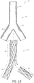
- FIG. 1A is a schematic representation of an example of a bifurcated vascular prosthesis 50 that can be used with any embodiment and/or example of the deployment catheter disclosed herein, positioned at the bifurcation between the abdominal aorta and the right and left common iliac arteries.
- FIG 1A there is illustrated a schematic representation of the abdominal part of the aorta and its principal branches.
- the abdominal aorta 30 is characterized by a right renal artery 2 and left renal artery 4.
- the large terminal branches of the aorta 30 are the right and left common iliac arteries 37 and 38.
- FIG. 1A One embodiment of an expanded bifurcated endoluminal vascular prosthesis is shown spanning aneurysms 103, 104 and 105.
- the expanded bifurcated endoluminal vascular prosthesis 50 can comprise a main branch portion 52 (also referred to herein as a main branch segment) for traversing the aorta, a first branch portion 54 (also referred to herein as a first branch segment or an ipsilateral branch portion) for spanning an ipsilateral iliac artery 37, and a second branch portion 56 (also referred to herein as a second branch segment or a contralateral branch portion) for spanning a contralateral iliac artery 38.
- a main branch portion 52 also referred to herein as a main branch segment
- first branch portion 54 also referred to herein as a first branch segment or an ipsilateral branch portion
- a second branch portion 56 also referred to herein as a second branch segment or a contralateral branch portion
- first and second branch portion can be used interchangeably and to refer to any branch vessel in the body, including but not limited to the ipsilateral vessel, the contralateral vessel, radial vessels, and subclavian vessels. Accordingly, in some embodiments, the "first” branch portion can refer to any branch portion including but not limited to the vessels set forth above. Similarly, the “second” branch portion can refer to any branch portion including but not limited to the vessels set forth above. In one embodiment, the first branch portion can refer to a downstream or upstream portion of a main branch vessel.
- the main branch portion and the first branch portion are configured to lie within at least a portion aortic arch (including, for example, the ascending and/or descending aorta) with main branch portion positioned closer to the heart while the second branch portion can be configured to extend into one of the branch vessels (left subclavian, right subclavian or carotid) that extend from the aortic arch.
- aortic arch including, for example, the ascending and/or descending aorta
- the second branch portion can be configured to extend into one of the branch vessels (left subclavian, right subclavian or carotid) that extend from the aortic arch.
- Figure 1B is an exploded view of the bifurcated prosthesis 50 of Figure 1A , which can include a preferably self-expanding wire support cage 60 and an outer polymeric sleeve 68.
- the wire support 60 is shown separated from an outer polymeric sleeve 68.
- the polymeric sleeve 68 can be situated concentrically outside of the tubular wire support 60.
- other examples can include a sleeve positioned instead concentrically inside the wire support or positioned on both the inside and the outside of the wire support.
- the wire support can be embedded within a polymeric matrix or layer which makes up the sleeve.
- the sleeve 68 can be attached to the wire support 60 by any of a variety of suitable manners known to those skilled in the art.
- the tubular wire support 60 can comprise a main branch portion 62 for traversing the aorta, a first branch portion 64 (also referred to herein as an ipsilateral branch portion) for spanning an ipsilateral iliac and a second branch portion 66 (also referred to herein as a contralateral branch portion) for spanning a contralateral iliac.
- the main branch portion 62 and first ipsilateral branch portion 64 can be formed from a continuous single length of wire having a proximal end, a distal end and a central lumen extending therebetween.
- the first ipsilateral branch portion 64 can be formed of one or more lengths of wire pivotably connected to the proximal end of the main branch portion 62.
- a second, contralateral branch component 66 can be formed of one or more lengths of wire pivotably connected to the proximal end of the main branch portion 62.
- Each of the iliac branch components has a proximal end, a distal end and a central lumen extending therethrough. Construction of the graft from a three part cage conveniently facilitates the use of different gauge wire in the different components (e.g. 0.356 mm (0.014 in.) diameter main trunk and 0.305 mm (0.012 in.) diameter branch components).
- each of the components of the bifurcated endoluminal vascular prosthesis 50 can vary considerably in diameter, length, expansion coefficient, and other parameters or characteristics, depending upon the intended application.
- the main branch portion 52 will have a length within the range of from approximately 50.1 mm (2 in.) or less to approximately 127 mm (5 in.) or more, and, typically within the range of from approximately 88.9 mm (3.5 in.) to approximately 102 mm (4 in.).
- the unconstrained outside expanded diameter of the main branch portion 52 will typically be within the range of from approximately 19.1 mm (.75 in.) to approximately 38.1 mm (1.5 in.).
- the unconstrained expanded outside diameter of the main branch portion 52 can be constant or substantially constant throughout the length, or can be tapered from a relatively larger diameter at the distal end to a relatively smaller diameter at the bifurcation.
- the diameter of the proximal end of the main branch portion can be on the order of no more than approximately 95% and, preferably, no more than approximately 85% of the diameter of the distal end of the main branch portion.
- the iliac branch portions 54 and 56 will typically be bilaterally symmetrical, having a length within the range of from approximately 10.2 mm (0.4 in.) to approximately 66 mm (2.6 in.), and a diameter within the range of from approximately 1.02 mm (0.04 in.) to approximately 20.1 mm (0.79 in.).
- the collapsed prosthesis for use in accordance with the present disclosure has a diameter in the range of approximately 2.03 mm (.08 in.) to approximately 9.91 mm (0.39 in.).
- the maximum diameter of the collapsed prosthesis can be in the range of approximately 3.05 mm (0.12 in.) to approximately 6.10 mm (0.24 in.) (4 mm to 6 mm (12 to 18 French)).
- Some embodiments of the deployment catheter, including the prosthesis can have a diameter in the range of from approximately 6 mm (18 French) to approximately 6.67 mm (20 French) or approximately 7 mm (21 French).
- Other embodiments can have a diameter as low as approximately 6.33 mm (19 French), approximately 5.33 mm (16 French), approximately 4.66 mm (14 French), or smaller.
- the expanded endoluminal vascular prosthesis can radially self-expand to a diameter anywhere in the range of approximately 20.3 mm (0.8 in.) to approximately 40.6 mm (1.6 in.).
- prostheses which are deployable using the embodiments and/or examples of a deployment catheter and guidewire assembly described herein.
- the delivery system described below can be used to deliver and deploy other types of self-expandable bifurcated or multi-segmented prosthesis having a main branch portion and at least one branch graft portion, as will be apparent to those of skill in the art in view of the disclosure herein.
- certain features and aspects of the deployment catheter and guidewire assembly can be used to deploy a graft without a branch graft portion, a graft with only one branch portion and/or a graft with more than one graft portions. Further details and additional embodiments and/or examples of the prosthesis described above can be found in U.S. Patent Nos. 6,007,296 , 6,187,036 , and 6,197,049 .
- the deployment catheter 120 can be configured to treat defects that may include, but are not limited to, abdominal aortic aneurysms, subclavian aneurysms, and thoracic aortic aneurysms, to name a few. It is also anticipated that certain features and aspects of the system described herein can be adapted to deliver a single straight graft segment to the thoracic aorta or other vessels or arteries within the body.
- the self-expandable bifurcation graft can be deployed at a treatment site with any of a variety of deployment catheters, as will be apparent to those of skill in the art.
- Any of the embodiments and/or examples of the deployment catheters disclosed herein can comprise any of the materials, features, or other details of any deployment catheters suitable for deploying a self-expanding bifurcation graft known in the field, or in any of the embodiments and/or examples disclosed in U.S. Patent No. 6,090,128 , U.S. Patent No. 6,500,202 , U.S. Patent No. 6,660,030 , U.S. Patent Application Serial No.
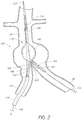
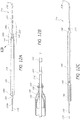
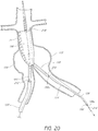
- FIG. 2 is a schematic representation of an embodiment of a deployment catheter 120 for delivering a bifurcated prosthesis or graft 178, showing a proximal portion of the main branch portion 180 of the graft 178 at least partially deployed within the aorta for illustration purposes.
- the deployment catheter 120 has preferably been introduced into a patient's vasculature through a puncture site in the patient's ipsilateral artery.
- the deployment catheter 120 is not limited to treatment of an abdominal aortic aneurysm, it can be configured to treat other aneurysms as discussed more fully herein. Additionally, depending on the clinical requirements, the deployment catheter 120 can be introduced into the patient's vasculature through puncture sites other than the ipsilateral artery. For example, without limitation, the deployment catheter 120 can be introduced into the patient's vasculature through the contralateral artery, through the radial artery, or through the subclavian artery.
- the deployment catheter 120 has preferably been advanced over a guidewire 226 to the desired location within the patient's aorta.
- the graft 178 illustrated in Figure 2 can comprise a main branch portion 180 constrained within a main branch sheath or member 186, an ipsilateral branch portion 182 constrained within and ipsilateral branch sheath or member 188, and a contralateral branch portion 184 constrained within a contralateral branch sheath or member 190.
- the entire graft was preferably constrained within an outer sheath 128 of the deployment catheter 120.
- the graft 178 was exposed by retracting the outer sheath 128, and the deployment catheter 120 was manipulated so as to position the contralateral branch portion 184 in the contralateral artery 38.
- the main branch portion 180 of the graft 178 was deployed by retracting a sheath release wire 166, which caused the perforated main branch sheath 186 to tear along a side thereof.
- the remaining portion of the main branch portion 180 can be deployed by further withdrawing the sheath release wire 166.
- the contralateral branch portion 184 of the graft 178 can be deployed by withdrawing the guidewire sheath 216 through a puncture site in the contralateral iliac artery 38, causing the contralateral branch sheath 190 to be withdrawn.
- the main branch sheath 186 can also be connected to the contralateral guidewire sheath 216 and can be withdrawn with the contralateral branch sheath 190.
- the ipsilateral branch portion 182 of the graft 178 can be deployed by withdrawing the deployment catheter 120 through a puncture site in the ipsilateral iliac artery 37, causing the ipsilateral branch sheath 188 to be withdrawn.
- the deployment method described with reference to Figure 2 is not intended to limit the applicability of the deployment catheter 120.
- the deployment catheter described herein can be configured to deploy a straight, bifurcated, or any other graft configuration into any portion of an artery or other blood vessel in the body.
- the deployment catheter 120 can be used to deploy grafts having anchoring elements that help secure the graft to the vessel wall as well as grafts that do not have anchoring elements.
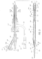
- FIG 3 is a cross-sectional view of an embodiment of a deployment catheter 120 for delivering a bifurcated vascular prosthesis, such as but not limited to the prosthesis 50 described above.
- the deployment catheter 120 can comprise an elongate flexible, multi-component tubular body 122 having a proximal end 124 and a distal end 126.
- the tubular body 122 and other components of this system can be manufactured in accordance with any of a variety of techniques well known in the catheter manufacturing field. Suitable materials and dimensions can be readily selected taking into account the natural anatomical dimensions in the iliacs and aorta, together with the dimensions of the desired percutaneous access site.
- the elongate flexible tubular body 122 can comprise an outer sheath 128 that can be supported by a valve member 130.
- the outer sheath 128 can be axially and radially supported by the valve member 130 so that the outer sheath 128 and valve member 130 translate and rotate in unison so that the rotation or translation of the valve member 130 can cause commensurate rotation or translation of the outer sheath 128.
- the tubular body 122 can also comprise a central inner core 132 that can be supported within the outer sheath 128 so as to be axially moveable within the outer sheath 128.
- a support sleeve 136 can be positioned adjacent to the valve member 130 and adhered or otherwise attached to the outside of the outer sheath 128 to provide additional stiffness or support to the outer sheath 128 adjacent to the valve member 130.
- the outer sheath 128 can comprise a valve member 130 at the proximal end of the outer sheath 128.
- the valve member 130 can have a hemostatic valve 134 that can provide an access port for the infusion of drugs or contrast media as will be understood by those of skill in the art.
- the outer tubular sheath 128 can comprise extruded PTFE, having an outside diameter of approximately 6.35 mm (0.250 in.) and an inside diameter of approximately 5.84 mm (0.230 in.) In some embodiments, the outer sheath 128 can have an outside diameter of between approximately 6 mm (18 French) and approximately 7.33 mm (22 French).
- the outer sheath 128 can be formed from PEBAX, nylon, polyethylene, or any other material that is suitable for endovascular delivery systems.
- the outer sheath 128 can be a thin-walled, collapsible sheath.
- the outer sheath 128 can comprise an inner liner, an outer layer, and an embedded metal braid or metal wire coil.
- the inner liner can be comprised from PTFE or any other suitable material that can provide a low friction surface for passage of the inner core 132.
- the outer layer can be formed from a soft, thin-walled plastic such as PEBAX, but can be made from any other suitable material.
- the outer layer can be formed from a material that is soft enough to permit the lumen of the outer sheath 128 to reopen after a kink or constriction has been formed in the outer sheath 128.
- the outer sheath 128 can be reinforced with a metal coil instead of the metal braid.
- the metal braid or coil can be formed from stainless steel, nitinol, or any other suitable material including, but not limited to, shape memory materials.
- the sheath 128 can have sufficient memory to recoil from a collapsed position into a patent position such that any kinks in the outer sheath 128 are easily opened when the inner core 132, or other diagnostic or therapeutic catheter based devices known to the art, can be passed through the outer sheath 128. As such, only a small force can be required to pass the inner core 132 through any portions of the outer sheath 128 that have become kinked or collapsed.
- the outer sheath 128 can provide a patent lumen suitable for highly tortuous anatomies where traditional outer sheath materials can kink or collapse.
- the liner can have a wall thickness less than or equal to approximately 0.0508 mm (0.002 in.). However, in some embodiments, the liner can have a wall thickness from approximately 0.0254 mm (0.001 in.) or less to approximately 0.0762 mm (0.003 in.), or from approximately 0.0762 mm (0.003 in.) to approximately 0.127 mm (0.005 in.) or more. In some embodiments, the metal braid or coil can have a thickness of less than or equal to approximately 0.0508 mm (0.002 in.).
- the metal braid or coil can have a wall thickness from approximately 0.0254 mm (0.001 in.) or less to approximately 0.0762 mm (0.003 in.), or from approximately 0.0762 mm (0.003 in.) to approximately 0.127 mm (0.005 in.) or more.
- the outer layer can have a wall thickness less than or equal to approximately 0.254 mm (0.01 in.) and a Durometer hardness value less than or equal to approximately 72D.
- the outer layer can have a wall thickness from approximately 0.127 mm (0.005 in.) to approximately 0.203 mm (0.008 in.), or from approximately 0.203 mm (0.008 in.) to approximately 0.279 mm (0.011 in.) or more, and a Durometer hardness value from approximately 55D or less to approximately 65D, or from approximately 65D to approximately 75D or more.
- the thickness, dimension, shape, hardness, and other aspects of the configurations of each of the materials comprising the outer sheath 128 are not limited to those described herein, but can be of any thickness, dimension, shape, or hardness suitable for endovascular delivery systems.
- the outer tubular sheath 128 can have an axial length within the range of from approximately 381 mm (15 in.) or less to approximately 559 mm (22 in.) or more. In one embodiment of the deployment catheter 120 having an overall length of 838 mm (33 in.), the axial length of the outer tubular sheath 128 can be approximately 381 mm (15 in.) and the outside diameter can be less than or equal to approximately 7.11 mm (0.28 in.). In some embodiments, the distal end 128a of the tubular sheath 128 can be located at least approximately 50.8 mm (2 in.) from the distal end of the distal tip 174 of the deployment catheter 120, in a prosthesis loaded configuration.
- the central inner core 132 can be axially and rotatably movable within the outer sheath 128.
- the central inner core 132 can be rotationally fixed relative to the outer sheath 128. Rotational engagement can be accomplished in any of a variety of ways, normally involving complementary surface structures such as keys or splines on the associated components.
- the central inner core 132 can be provided with a radially outwardly extending projection along a portion or all of its axial length. This projection can be slidably received within a radially outwardly extending slot on the interior surface of the outer sheath 128.
- a radially inwardly extending projection on the outer sheath 128 or associated component can be received with an axially extending recess on the outer surface of the central inner core 132.
- any of a variety of non-round configurations for the central inner core 132 such as elliptical, ovular, triangular, square, polygonal, circular with flat sides, and the like, can be slidably received within a complementary-shaped aperture on or connected to the outer sheath 128.
- the inner core 132 and the valve member 130 can define complementary flat surfaces or other features such as, but not limited to, those described above that prevent the inner core 132 from rotating relative to the valve member 130, while the inner lumen of the outer sheath 128 can be circular. Additionally, in some embodiments, the valve member 130 can be tightened around the outer surface of the inner core 132 so as to substantially prevent the inner core 132 from translating and/or rotating relative to the valve member 130.
- Figure 3A is cross-sectional view of the illustrated embodiment of the deployment catheter 120 taken along line 3A-3A of Figure 3 .
- the cross-section of the central inner core 132 can be circular.
- the cross-section of the central inner core 132 can deviate from a circular cross-section by the provision of one or two opposing flat sides extending axially along the length of the inner core 132.
- an aperture with a corresponding cross-section can be provided in the outer sheath 128 and/or the valve member 130 such that the rotation of the outer sheath 128 or the valve member 130 can cause a similar rotation of the central inner core 132.
- the inner core can comprise a guidewire lumen 154 and a sheath release lumen 156 extending longitudinally therethrough.
- the guidewire lumen 154 can extend throughout the entire length of the tubular central core 132, having a distal exit port 158 and a proximal access port 160, as will be understood by those of skill in the art.
- the deployment catheter 120 can be advanced into position in the aorta over a guidewire extending through the guidewire lumen 154, as will be understood by those of skill in the art.
- a sheath release wire 166 (also referred to herein as a suture), which will be described in greater detail below, can be routed through the sheath release lumen 156.
- the sheath release lumen 156 can extend through the entire length of the tubular central core 132, having a distal exit port 162 (shown most clearly in Figure 4 ) and a proximal access port 164 (shown most clearly in Figure 3 ), as will be understood by those of skill in the art.
- the guidewire lumen 154 can be co-planar with the centerline axis of the inner core 132 and the sheath release lumen 156.
- this arrangement is not required.
- the guidewire lumen 154 can be non-coplanar with the centerline axis of the inner core 132 and the sheath release lumen 156. Therefore, as illustrated in Figure 3B , the inner core 132 can be configured so that the guidewire lumen 154 and the sheath release lumen 156 are formed at any desired position in the cross-section of the inner core 132.
- the sheath release wire 166 can be attached to a tabbed handle 167 that can be supported by a "Y" connector 169.
- the handle 167 can be configured to enable the user or medical practitioner to manipulate the sheath release wire 166.
- the handle 167 can be removable from the "Y" connector 169 so that the medical practitioner or user can manipulate the handle 167 and, hence, the sheath release wire 166, independent of the "Y" connector 169.
- the handle 167 can be threadedly and, hence, removably supported by the "Y" connector 169.
- the handle 167 can be attached to, but configured to break away from, the "Y" connector 169 when the user or medical practitioner exerts a threshold force or to work on the handle 167 relative to the "Y” connector 169.
- the handle 167 can be press fit into a complementary opening in the "Y” connector 169 so that the medical practitioner or user can remove the handle 167 from the "Y” connector 169 by pulling and/or turning the handle 167 relative to the "Y” connector 169.
- the sheath release wire 166 can pass through a first port 169a in the "Y" connector 169 and so on through the sheath release lumen 156 as described above.
- the guidewire discussed above that can extend through the central guidewire lumen 154 can pass through a second port 169b in the "Y" connector 169.
- the "Y" connector 169 can be secured to the proximal end of the inner core 132 such as by thermal bonding, adhesive bonding, and/or any of a variety of other securing techniques known in the art.
- An interface member 168 can be secured to the distal end of the inner core 132 such as by thermal bonding, adhesive bonding, and/or any of a variety of other securing techniques known in the art.
- the interface member 168 can be axially and rotationally secured to the inner core 132.
- the interface member 168 can be configured to axially and rotationally support a central tube 170 so that the central tube 170 cannot substantially rotate or translate axially relative to the inner core 132.
- the central tube 170 can define a lumen axially therethrough that can be axially aligned with the guidewire lumen 154 so that a guidewire that can be advanced through the guidewire lumen 154 can also be advanced through the lumen of the central tube 170.
- a wire support 172 can be attached to the outside of the central tube 170 and supported by the interface member 168 to provide additional support to the central tube 170.
- the tubing 170 can be formed from any suitable plastic or metal material, such as but not limited to stainless steel or nitinol, or any other material that is suitable for endovascular delivery systems.
- the tubing 170 can be formed of braided metal so as to provide flexibility, tensile strength, and torsional strength.
- the tubing 170 can be formed from multiple materials, including but not limited to being formed of a braided metal outer sheath that is lined with a plastic or other suitable material for support and/or to reduce frictional forces from a guidewire advanced therethrough.
- a distal segment of the deployment catheter 120 can comprise an elongate, flexible tapered distal tip 174.
- the distal tip 174 can be supported by the central tube 170.
- the distal tip 174 can over molded onto an anchor 176 that can be secured to the outside surface of the central tube 170.
- the distal tip 174 can be axially and rotationally supported on the central tube 170 so that the distal tip 174 can be substantially prevented from any axial movement or rotation relative to the central tube 170.
- the central tube 170 can be configured to define a longitudinal opening therethrough, the longitudinal opening or lumen can be axially aligned with the guidewire lumen 154 such that a guidewire extending through the guidewire lumen 154 can also extend through the lumen in the central tube 170.
- the central tube 170 can protrude into the distal tip 174 to a short distance beyond the location of the anchor 176. In some embodiments, however, at least a portion of the anchor 176 can extend all the way to the end of the distal tip 174, or beyond.
- an aperture or opening 177 in the distal tip 174 can be axially aligned with the opening in the central tube 170, such that a guidewire passing through the opening in the central tube 170 can also pass through the opening 177 in the distal tip 174.
- the distal tip 174 can be substantially axially and rotationally fixed to the inner core 132 such that the axial and rotational positioning of the distal tip 174 can be controlled by the axial and rotational positioning of the inner core 132.
- the distal tip 174 can taper from an outside diameter of approximately 5.72 mm (0.225 in.) at its proximal end to an outside diameter of approximately 1.78 mm (0.070 in.) at the distal end thereof.
- the overall length of the distal tip 174 can be approximately 63.5 mm (2.5 in.).
- the length and rate of taper of the distal tip 174 can be varied depending upon the desired trackability and flexibility characteristics, as well as other factors.
- Figure 4 is an enlargement of the portion delineated by the curve 4 in Figure 3 .
- Figures 5 and 6 are a cross-sectional view of the embodiment of the deployment catheter shown in Figure 3 taken along line 5-5 and line 6-6, respectively, of Figure 4 .
- a bifurcated endoluminal graft 178 is illustrated in a compressed configuration within the deployment catheter 120, prior to the advancement of the inner core 132 relative to the other sheath 128.
- the graft 178 can comprise a distal aortic trunk or main branch portion 180, a proximal ipsilateral branch portion 182, and a proximal contralateral iliac portion 156.
- the aortic main branch portion 180 of the graft 178 can be constrained within a main branch sheath 186. While the embodiment of main branch sheath 186 is shown with reference to compressing a main branch graft portion 180, it is envisioned that the sheath 186 could alternatively be used to compress and deliver other portions of a multi-segmented vascular graft, such as a branch graft portion, the entire multi-segmented graft, or a single-segment, straight vascular graft.
- the ipsilateral branch portion 182 can be constrained with a preferably tubular ipsilateral branch sheath 188 (also referred to herein as the first branch sheath), and the contralateral branch portion 184 (also referred to herein as the second branch sheath) can be constrained within a preferably generally tubular contralateral branch sheath 190.
- the ipsilateral branch sheath 188 and the contralateral branch sheath 190 can be open-ended tubular sheaths.
- the ipsilateral branch sheath 188 can constrain substantially the entire length of the ipsilateral branch portion 182 of the bifurcated graft 178.
- the contralateral branch sheath 190 can constrain substantially the entire length of the contralateral branch portion 184 and of the bifurcated graft 178.
- the ipsilateral branch sheath 188 and/or the contralateral branch sheath 190 can constrain substantially more or less than the entire length of the ipsilateral branch portion 182 or the contralateral branch portion 184, respectively, of the bifurcated graft 178.
- the main branch sheath 186 can be sized and configured to cover the entire length of the bifurcated graft 178. However, in some examples, the main branch sheath 186 can be configured to constrain only the length of the main branch portion 180 of the bifurcated graft 178. Thus, even though the main branch sheath 186 can extend to the distal end of the contralateral branch portion 184 of the graft 178, in some embodiments, the main branch sheath 186 can be configured so as to define a notch 192 along the portion of the length of the main branch sheath 186 that covers the contralateral branch portion 184.
- the notch 192 can be a slit along a portion of the length of the main branch sheath 186. In some embodiments, as in the illustrated embodiment, the notch 192 can remove a portion of the main branch sheath 186 along a portion of the length of the main branch sheath 186 that can be less than or equal to approximately half of the perimeter of the main branch sheath 186. In some embodiments, the main branch sheath 186 can be skived to remove a suitable amount of the material comprising the main branch sheath 186 to allow the ipsilateral or contralateral branch portion 182, 184 of the graft 178 to deploy upon retraction of the outer sheath 128. Thus, in some embodiments, the main branch sheath 186 preferably does not constrain the ipsilateral or contralateral branch portion 182, 184 of the bifurcated endoluminal graft 178.
- a torsion tab 196 can be integrally formed with the central tube 170, or secured thereto such as by thermal bonding, adhesive bonding, and/or any of a variety of other securing techniques known in the art.
- the main branch portion 180 of the bifurcated endoluminal graft 178 can be constrained by the main branch sheath 186 around the torsion tab 196.
- the torsion tab 196 can engage with the endoskeleton or, with reference to Figure 1B , the wire support cage 60 of the bifurcated graft 178 and ensures that the bifurcated graft 178 substantially rotates with the inner core 132 of the deployment catheter 120.
- the torsion tab 196 can prevent the central tube 170 from rotating relative to the bifurcated graft 178. This can enhance the ability of the medical practitioner or user to rotate and, hence, maneuver, the graft 178 and the ipsilateral and/or contralateral branch portions 182, 184 within the patient's aorta by rotating the proximal end of the deployment catheter 120, in particular, by rotating the proximal end of the inner core 132 or the "Y" connector 169. As such, the torsion tab 196 can cause of the bifurcated endoluminal graft 178 to rotate substantially in unison with the central tube 170.
- the main branch sheath 186 can be retracted through the contralateral iliac artery using a contralateral guidewire 194 after the main branch portion 180 of the bifurcated endoluminal graft 178 has been deployed.
- the contralateral guidewire 194 can define a lumen longitudinally therethrough, so that a smaller diameter guidewire can be advanced therethrough.
- the contralateral branch sheath 190 can be deployed using the contralateral guidewire 194.
- the contralateral guidewire 194 and the constricted end portion 186a of the main branch sheath 186 can be configured so that the contralateral guidewire 194 can be substantially permitted to slide through the opening in the constricted end portion 186a of the main branch sheath 186 while stops or tabs positioned on the guidewire 194 are prevented from sliding through constricted portion 186a.
- a tab 198 can be attached to the outside surface of the contralateral guidewire 194 such as by thermal bonding, adhesive bonding, and/or any of a variety of other securing techniques known in the art.
- the tab 198 can be positioned and configured such that, as the contralateral guidewire 194 slides through the end portion 186a of the main branch sheath 186, the tab 198 can be prevented from sliding through the constricted opening in the end portion 186a of the main branch sheath 186.
- a contralateral graft tab 200 can be positioned near to, or approximately adjacent to, the first end 194a of the contralateral guidewire 194 to engage and retract the contralateral branch sheath 190, as described in more detail below.
- the contralateral guidewire 194 can be approximately 160 cm. (63 in.) in length. In some embodiments, the contralateral guidewire 194 can be approximately 170 cm. (67 in.), or approximately 180 cm. (71 in.). Because the contralateral guidewire 194 can be positioned within or integrated into the deployment catheter 120 in the pre-deployment state, the contralateral guidewire 194 can be shorter than the conventional guidewires (e.g., the typical 300 cm. exchange length guidewires) that were typically inserted by the medical practitioner into a catheter for gaining access to, for example, the thoracic aortic region.
- conventional guidewires e.g., the typical 300 cm. exchange length guidewires
- a 0.356 mm (0.014 in.) guidewire can be advanced through the contralateral guidewire 194 and into the deep thoracic aortic region before (or after) the main branch portion 180 of the graft 178 is deployed.
- the contralateral guidewire 194 can be configured so that a 0.457 mm (0.018 in.), or a 0.889 mm (0.035 in.), or any other suitable guidewire can be advanced therethrough.
- the length of the contralateral guidewire 194 of this configuration can be short as 160 cm.
- the 0.356 mm (0.014 in.) guidewire that can be advanced through the contralateral guidewire 194 can similarly have a shorter length than the conventional guidewires that were used for this purpose.
- a 0.356 mm (0.014 in.) guidewire having a length of approximately 180 cm. (71 in.) or 190 cm. (75 in.) can be used.
- the contralateral guidewire 194 and other guidewires disclosed herein can be formed in any suitable lengths and are not restricted to the dimensions disclosed herein.
- the contralateral guidewire 194 can define a first end (or also referred to as a distal end) 194a, as shown most clearly in Figure 8 , and a second end (or also referred to as a proximal end) 194b.
- the second and 194b can be advanced through a puncture site in the patient's vasculature so that, when the delivery device 120 is positioned within the patient's vasculature, the second end 194b of the contralateral guidewire 194 can be located outside of the patient's body and, hence, directly accessible by the medical practitioner or user.
- the guidewire 194 can be looped back around within the outer sheath 128 so as to be routed back toward the distal tip 174.
- the majority of the length of the guidewire 194 can be positioned outside of the deployment catheter 120, having exited the deployment catheter 120 between the distal end 128a of the tubular sheath 128 and the distal tip 174.
- linear grooves or depressions 175 can be formed in the distal tip 174 so that the contralateral guidewire 194 can pass between the distal tip 174 and the outer sheath 128 without substantially binding or obstructing the free axial movement of the distal tip 174 relative to the outer sheath 128.
- both ends of the contralateral guidewire 194 can be arranged so as to pass between the distal tip 174 and the outer sheath 128 and can be positioned within the grooves or depressions 175 can be formed in the distal tip 174.
- the contralateral guidewire 194 and the constricted end portion 190a of the contralateral branch sheath 190 can be configured so that the contralateral guidewire 194 can be substantially permitted to slide through the opening in the constricted end portion 190a of the contralateral branch sheath 190.
- the tab 200 can be attached to the outside surface of the contralateral guidewire 194 such as by thermal bonding, adhesive bonding, and/or any of a variety of other securing techniques known in the art.
- the tab 200 can be positioned and configured such that, as the guidewire 194 slides through the end portion 190a of the contralateral branch sheath 190, the tab 200 can be prevented from sliding through the constricted opening in the end portion 190a of the contralateral branch sheath 190.
- the contralateral graft tab 200 abutted against the constricted end portion 190a of the contralateral branch sheath 190, as the contralateral guidewire 194 is further retracted through the contralateral iliac artery, the contralateral graft tab 200 will cause the contralateral branch sheath 190 to also be retracted through the contralateral iliac artery. This can cause the contralateral branch portion 184 of the graft 178 to be deployed.
- the central tube 170, the ipsilateral branch portion 182 of the bifurcated graft 178, and the ipsilateral branch sheath 188 can be offset within the outer sheath 128 from the centerline throughout a portion of the length deployment catheter 120.
- the guidewire lumen 154 through which the central tube 170 can pass can also be offset within the inner cone 132 to accommodate the offset of the central tube 170, the ipsilateral branch portion 182, and the ipsilateral branch sheath 188 from the centerline of that portion of the deployment catheter.
- Offsetting the central tube 170, the ipsilateral branch portion 182, and the ipsilateral branch sheath 188 provides more space within the outer sheath 128 for the contralateral guidewire 194, contralateral branch portion 184 of the bifurcated graft 178, the contralateral branch sheath 190, and the main branch sheath 186.
- the radial forces exerted on the inside surface of the outer sheath 128 from the ipsilateral and contralateral iliac portions of the grafts and sheaths can be reduced.
- extending the inner core 132 relative to the outer sheath 128 will require less force than if not offset, and the compression forces on each of the branches and respective sheaths in the pre-deployment state will be reduced.
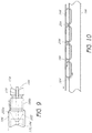
- Figures 7 and 8 are a side view and top view, respectively, of the main branch sheath 186 (also referred to herein as a restraint member) of the embodiment of the deployment catheter 120 shown in Figure 3 , before the deployment of the main branch portion 180 of the graft 178.
- Figure 9 is an enlarged detail view of Figure 7 taken along the curve 9 in Figure 7 .
- the distal end 186b of the main branch sheath 186 can be tapered or constricted so as to define a smaller cross-sectional diameter or size as compared to the main body portion of the main branch sheath 186.
- the smaller diameter of the distal end 186b can ensure that the main branch sheath 186 will be secured around the distal anchor member 202 in a manner that can prevent the main branch sheath 186 from moving or sliding relative to the distal anchor member 202.
- the distal anchor member 202 can define an annular protruding portion 202a that can substantially prevent the main branch sheath 186 from slipping relative to the distal tip 174.
- the distal anchor member 202 can comprise a linear groove or depression to accommodate the passage of the contralateral guidewire 194 (or, as explained below, one end of the guidewire sheath 216) that can pass between the distal anchor member 202 and the distal end portion 186b of the main branch sheath 186 in the pre-deployment state.
- any of the main branch sheath 186, the ipsilateral branch sheath 188, and the contralateral branch sheath 190 can be formed from balloon blown pebax, nylon, PET, PTFE, or any other suitable material.
- the sheath material can be selected so as to increase the tensile strength of the sheath.
- the material selected to form any of the sheaths can be at least partially opaque or colored. This can be beneficial for any of the processing that the sheaths may undergo, such as, but not limited to, laser cutting, laser etching, perforating, drilling, threading with sutures, or any of the other processing steps disclosed herein. For example, many lasers that are commonly used for etching, cutting, perforating, or other procedures require the sheath material to be partially opaque for such laser processing.
- Figure 10 is an enlarged section view through the axial centerline of the main branch sheath 186 shown in Figure 7 taken along the curve 10 in Figure 7 .
- Figure 11A is a cross-sectional view of the main branch sheath 186 shown in Figure 7 taken along line 11A-11A of Figure 7
- Figure 11B is an enlarged detail view of Figure 11A taken along the curve 11B in Figure 11A .
- the main branch sheath 186 preferably partially or fully covers the entire length of the bifurcated graft 178, although the main branch sheath 186 can not cover the entire circumference of the graft 178 along the entire length of the graft 178.
- the notch 192 can be formed along the portion of the main branch sheath 186 that can be approximately adjacent to the ipsilateral branch sheath 188.
- the notch 192 can allow the ipsilateral branch portion 182 of the bifurcated graft 178 to be manipulated away from the contralateral branch portion 184 of the bifurcated graft 178 before the main branch sheath 186 has been removed.
- the portion of the main branch sheath 186 that can constrain the main branch portion 180 of the draft 178 can be generally tubular shaped, as shown most clearly in Figures 7, 8 , and 11A .
- Perforations or openings 204 can be formed along one side of the main branch sheath 186. In some embodiments, as in the illustrated embodiment, the openings 204 can be linearly aligned.
- the main branch portion 180 of the bifurcated graft 178 can be deployed from the main branch sheath 186 by retracting sheath release wire 166 that can be threaded through each of the openings 204 as illustrated in Figure 10 , propagating a tear along the side of the main branch sheath 186 that has been perforated with the openings 204.
- the openings 204 can be spaced apart approximately 3.81 mm (0.15 in.). In some examples, the openings 204 can be spaced apart less than approximately 3.81 mm (0.15 in.), or from approximately 3.81 mm (0.15 in.) to approximately 5.08 mm (0.2 in.), or from approximately 5.08 mm (0.2 in.) to approximately 6.35 mm (0.25 in.) or more. In the illustrated embodiment, each of the openings 204 can have a circular shape and defines a diameter that can be slightly larger than twice the diameter of the sheath release wire 166 passing therethrough.
- each of the openings 204 can define a cutout or notch 208 formed in a portion of the periphery of each of the openings 204.
- the notches 208 are configured to assist the propagation of a tear at each opening 204 when the sheath release wire 166 is withdrawn, as will be understood by one of ordinary skill in the art.
- the openings 204 can be formed without any notches or cut-outs.
- each of the notches 208 can define a generally triangular shape. However, the shape of each notch 208 is not so limited, and can define any suitable shape.
- each opening 204 can define any shape that is desired or configured to cause the main branch sheath 186 to tear along the perforated side (i.e., along the openings 204) of the main branch sheath 186.
- each opening can have a triangular, square, or diamond shape and can be larger or smaller than the sizes disclosed above.
- one or more score lines or depressions 206 can be formed on the inside or the outside surface of the main branch sheath 186 along the tear line (i.e., between each of the openings 204) to help propagate or progress a tear along the main branch sheath 186.
- one or more of the openings 204 define a notch 208 formed in a portion of the opening 204, and a depression 206 has preferably been formed between one or more of the openings 204.
- the sheath release wire 166 can be routed through the openings 204 in any of a number of suitable ways. As shown most clearly in Figure 10 , the sheath release wire 166 can be routed through the openings 204 in the illustrated embodiment of the main branch sheath 186 as described below. As most clearly shown in Figure 3 , the proximal end 166a of the sheath release wire 166 can be routed through the deployment catheter 120 so as to be accessible to the medical practitioner. In the illustrated embodiment, with reference to Figure 3 , the proximal end 166a of the sheath release wire 166 can be secured to the tabbed handle 167 so that the sheath release wire 166 can be manipulated by manipulating the preferably removable tabbed handle 167.
- the sheath release wire 166 can be pulled or retracted by the medical practitioner to begin propagating tears in the main branch sheath 186, so as to begin deploying the main branch portion 180 of the graft 178. Further, portions of the main branch sheath 186 can define slits in the segments of the sheath 186 between one or more of the openings 204, such that the sheath 186 need not be torn at that portion.
- Figure 11D is an enlarged detail view of Figure 8 taken along the curve 11D in Figure 8 .
- a slit 210 has preferably been formed near the distal end 186b of the main branch sheath 186, connecting three of the openings 204 formed near the distal end 186b of the sheath 186.
- the sheath release wire 166 of the illustrated embodiment of the deployment catheter 120 can be routed through the openings 204 of the main branch sheath 186 as illustrated in Figures 7 and 8 such that the distal end 166b of the sheath release wire 166 is secured in a knot 212 positioned as shown in the referenced figures.
- one suitable routing of the sheath release wire 166 through the openings 204 is illustrated.
- the sheath release wire 166 can be looped around the each segment of the sheath 186 between each of the holes 204 so as to pass through most openings 204 in the sheath 186 at least two times.
- each of the segments of the main branch sheath 186 between each of the openings 204 will be sequentially torn by the wire 166 such that the main branch portion 180 of the graft 178 adjacent thereto will be deployed.
- the sheath release wire 166 can also be routed as disclosed in U.S. Patent Application Serial No. 11/522,292 referenced above.
- the main branch sheath 186 can be configured such that the main branch portion 180 of the bifurcated graft 178 can be deployed in a number of different ways.
- the main branch sheath 186 can be configured so that the main branch portion 180 can be deployed first at the distal end of the main branch portion 180 and then sequentially deployed toward the proximal end of the main branch portion 180.
- the main branch sheath 186 can be configured so that the main branch portion 180 can be deployed first at the proximal end of the main branch portion 180 and then sequentially deployed toward the distal end of the main branch portion 180.
- the main branch sheath 186 can be configured such that the main branch portion 180 of the graft 178 can be deployed in any combination of deployment directions or sequences described herein or in any other suitable sequences for the deployment of the main branch portion 180.
- the illustrated main branch sheath 186 can be configured so that, as the sheath release wire 186 is retracted, the deployment of the main branch portion 180 of the graft 178 begins at the proximal end of the main branch portion 180 and moves toward the distal end of the main branch portion 180.
- the tear along the openings 204 in the main branch sheath 186 can be propagated by pulling on the sheath release wire 166 until the tear reaches the opening 204a (illustrated in Figures 7 and 8 ).
- the sheath release wire 166 can be routed to the distal end 186b of the sheath 186 so as to bypass the openings 204 between the opening 204a and the distal end 186b of the sheath 186.
- the sheath release wire 166 can be looped back through the opening 204b (illustrated in Figures 7 and 8 ) so as to form a loop around the segment of the sheath 186 between the distal end 186b of the sheath 186 and the opening 204b.
- the main branch portion sheath 186 and the sheath release wire 166 can be configured so that the knot 212 formed at the distal end 166b of the sheath release wire 166 is not positioned adjacent to or aft of the distal end 186b of the main branch sheath 186. Positioning the knot 212 fore of the distal end 186b can prevent the knot 212 from getting caught or snagged on the distal end of the main branch portion 180 of the graft 178 after the distal end of the main branch portion 180 of the graft 178 has been deployed.
- the knot 212 can be positioned adjacent to or aft of the aft end 186b of the main branch sheath 186, or in any other desired or suitable location.
- knot 212 can be positioned adjacent to the distal end of the notch 192 formed in the main branch sheath 186, or at any location between the distal end of the notch 192 and the aft end 186b of the main branch sheath 186.
- the sheath release wire 166 and inner core 132 can be configured and routed as will be understood by one of ordinary skill in the art so that, after the release wire 166 has caused the sheath 186 to be split and the main branch portion 180 of the graft 178 deployed, further retraction of the release wire 166 will withdraw the main branch sheath 186 partially or fully toward or into the ipsilateral iliac artery.
- a slit 210 has preferably been formed between the openings 204b and 204c, after the segment of the sheath 186 between the distal end 186b of the sheath 186 and the opening 204b has been torn, the distal end of the main branch portion 180 of the graft 178 (i.e., the portion of the main branch portion 180 of the graft 178 adjacent to and aft of the opening 204c) can be substantially deployed. Further retraction of the sheath release wire 166 can propagate a tear in the section of main branch sheath 186 between the opening 204c and the proximal end 186a of the sheath 186.
- the final segment of the sheath 186 that will be torn can be the segment of the sheath 186 between the openings 204d and 204a. Note that, as the segment of the sheath 186 between the openings 204d and 204a is torn by further retraction of the wire 166, the main branch portion 180 of the graft 178 will be substantially fully deployed, and the knot 212 formed near the distal end 166b of the branch release wire 166 can be retracted by the medical practitioner away from the main branch portion 180 of the bifurcated graft 178.
- proximal retraction of the outer sheath 128 relative to the inner core 132 distal interface of the inner core 132 relative to the outer sheath 188 can release the compressed iliac branches 182 and 184 of the graft 178 so that they are no longer constrained within the outer sheath 128.
- the iliac branches 182 and 184 can remain compressed and constrained within the ipsilateral and contralateral branch portion sheaths 188, 190, respectively, until the sheaths 188, 190 are removed.
- the ipsilateral branch sheath 188 can be configured to constrain the ipsilateral branch portion 182 of the graft 178 in the constrained configuration, for implantation at the treatment site.
- the ipsilateral branch sheath 188 can be connected to the inner core 132 or the interface member 168 and can be adapted to be axially proximally withdrawn from the ipsilateral branch portion 182 of the graft 178, thereby permitting the ipsilateral branch portion 182 to expand to its implanted configuration.
- the ipsilateral branch sheath 188 can comprise a thin walled PTFE extrusion having an outside diameter of approximately 5.46 mm (0.215 in.) and an axial length of approximately 50.8 mm (2 in.) to approximately 76.2 mm (3 in.).
- a proximal end of the ipsilateral branch sheath 188 can be necked down such as by heat shrinking to secure the ipsilateral branch sheath 188 to the interface member 168.
- a distal portion of the interface member 168 can flare outwardly to provide a better securement for the ipsilateral branch sheath 188.
- proximal withdrawal of the inner core 132 preferably after the main branch portion 180 of the bifurcated graft 178 has been deployed
- the ipsilateral branch sheath 188 can be a tubular sheath with an open end, the ipsilateral branch portion 182 of the graft 178 can be deployed in a top-down direction (i.e., the portion of the ipsilateral branch portion 182 closest to the main branch portion 180 can be the first portion to deploy).
- the main branch sheath 186 and the contralateral branch sheath 190 can be connected to the contralateral guidewire 194, as described above.
- the contralateral branch sheath 190 can be adapted to restrain the contralateral branch portion 184 of the graft 178 in the reduced or constrained state.
- the contralateral branch sheath 190 can have an outside diameter of approximately 5.46 mm (0.215 in.) and an axial length of approximately 50.8 mm (2 in.) to approximately 76.2 mm (3 in.).
- the contralateral branch sheath 190 can have a smaller cross-section than the ipsilateral branch sheath 188, due to the smaller diameter of the contralateral guidewire 194 positioned on the inside of the constrained contralateral branch portion 184 of the graft 178 as compared to the diameter of the central tube 170 positioned on the inside of the constrained ipsilateral branch portion 182 of the graft 178.
- Proximal retraction of the contralateral guidewire 194 through the contralateral iliac artery can proximally withdraw the contralateral branch sheath 190 from the contralateral graft portion 184, thereby deploying the contralateral graft portion 184.
- Figure 12A is a schematic representation of the dual concentric guidewire assembly of the embodiment of the deployment catheter 120 shown in Figure 3 , showing the position of the main branch sheath 186 and the contralateral branch sheath 190 before deployment of the main branch portion 180 of the graft 178.
- Figure 12B is an enlarged detail view of Figure 12A taken along the curve 12B in Figure 12A .
- the contralateral guidewire 194 can be a dual concentric guidewire assembly 214 comprising a hollow guidewire sheath 216 and an inner core wire 218 that can be axially advanced through a lumen 220 in the guidewire sheath 216.
- the length of the hollow guidewire sheath 216 can be the same as is disclosed for the contralateral guidewire 194 described above, or any other suitable length. Any reference herein the guidewire assembly 214 can be interpreted as a reference to the guidewire 194, since both can be used interchangeably
- the preferably annular tab 198 can be attached to the outside surface of the hollow guidewire sheath 216 such that, in use, proximal retraction of the hollow guidewire sheath 216 can cause the tab 198 to engage the main graft sheath 186 so that the main graft sheath 186 can be retracted through the contralateral iliac artery after deployment of the main branch portion 180 of the graft 178.
- the main branch sheath 186 can be formed around an annular ring 222 through which the guidewire sheath 216 can pass. The ring 222 can help prevent the tab 198 from passing through the proximal end 186a of the main branch sheath 186 so that the main branch sheath 186 can be engaged when the guidewire sheath 216 is retracted.
- the preferably annular tab 200 can be attached to the outside surface of the hollow guidewire sheath 216 such that, in use, further proximal retraction of the hollow guidewire sheath 216 can cause the tab 200 to engage the contralateral branch sheath 190 so that the contralateral branch portion 184 of the graft 178 can be deployed, and so that the contralateral branch sheath 190 can be retracted through the contralateral iliac artery.
- the contralateral branch sheath 190 can be formed around a ring similar to ring 222 described above to preferably further prevent the tab 200 from passing through the proximal end 190a of the contralateral branch sheath 190 so that the contralateral branch sheath 190 can be engaged when the guidewire sheath 216 is retracted. Because the contralateral branch sheath 190 can be a tubular sheath with an open end, the contralateral branch portion 184 of the graft 178 can be deployed in a top-down direction (i.e., the portion of the contralateral branch portion 184 closest to the main branch portion 180 can be the first portion to deploy).
- the main branch sheath 186 can be configured so as to at least partially surround the contralateral branch sheath 190.
- the tab 198 can be positioned on the guidewire sheath 216 approximately adjacent to, but between the distal end 186a of the main branch sheath 186 and the distal end 190a of the contralateral branch sheath 190. In this configuration, any retraction of the guidewire sheath 216 can cause retraction of the main branch sheath 186 before the contralateral branch sheath 190 is retracted.
- the guidewire sheath 216 can be positioned within the main branch portion 180 of the graft 178 such that the distal end 216a of the guidewire sheath 216 extends beyond the distal end of the main branch portion 180 of the graft 178.
- the distal end 216a of the guidewire sheath 216 can pass between the distal tip 174 and the outer sheath 128 within a depression 175 can be formed in the distal tip 174.
- a 0.356 mm (0.014 in.) guidewire can be advanced through the guidewire sheath 216 and into deep thoracic aortic region before (or after) the main branch portion 180 of the graft 178 has been deployed.
- the contralateral branch tab 200 can be positioned near the distal end 216a of the guidewire sheath 216 at a distance away from the main branch tab 198 that is approximately greater than the overall length of the main branch sheath 186.
- the main branch sheath 186 can be substantially completely retracted so that the distal end 186b of the main branch sheath 186 can be approximately adjacent to or below (i.e., closer to the contralateral artery puncture site) relative to the proximal end 190a of the contralateral branch sheath 190.
- This configuration can prevent the main branch sheath 186 from becoming caught or snagged by the contralateral branch portion 184 of the graft 178 when the contralateral branch portion 184 is deployed. This configuration can also reduce the forces that can be induced on the contralateral iliac artery and other portions of the anatomy during the retraction of the main branch sheath 186 or during the deployment of the contralateral branch portion 184.
- the main graft tab 198 can be spaced apart from the contralateral graft tab 200 by a distance that can be approximately equal to or greater than the length of the main branch sheath 186. In some embodiments, the main graft tab 198 can be spaced apart from the contralateral graft tab 200 by more than approximately 12.7 mm (0.5 in.) or, alternatively, 19.1 mm (0.75 in.), less than the approximate length of the main branch sheath 186. In the illustrated embodiment, where the main branch restraint can be approximately 184 mm (7.25 in.) in length, the main graft tab 198 can be spaced apart from the contralateral graft tab 200 by at least approximately 171 mm (6.75 in.).
- the contralateral graft tab 200 can be spaced apart from the distal end 216a of the guidewire sheath 216 by approximately 19.1 mm (0.75 in.).
- the main graft tab 198 can be spaced apart from the contralateral graft tab 200 by approximately 171 mm (6.75 in.) to approximately 191 mm (7.5 in.) or more.
- the contralateral graft tab 200 can be spaced apart from the distal end 216a of the guidewire sheath 216 by approximately 25.4 mm (1 in.) or more.
- Figure 12C is a schematic representation of the dual concentric guidewire assembly 214 of the embodiment of the deployment catheter 120 of Figure 3 , showing the position of the main branch restraint member 186 and the contralateral branch restraint member 190 after the main branch portion 180 of the graft 178 has been deployed.
- Figure 12C illustrates a desired position of the main graft tab 198 relative to the contralateral graft tab 200 for the illustrated embodiment of the deployment catheter 120.
- Figure 12C illustrates a desired position of the main branch sheath 186 relative to the contralateral branch sheath 190 as both sheaths 186, 190 are being retracted by the guidewire sheath 216 and the main and contralateral graft tabs 198, 200.
- the contralateral guidewire assembly 214 can be configured to retract or withdraw the main branch sheath 186 after the main branch portion 180 of the graft 178 has been deployed by retraction of the sheath release wire 166. In some embodiments, however, the contralateral guidewire assembly 214 can be used in place of the sheath release wire 166 to deploy the main branch sheath 186.
- the contralateral guidewire assembly 214 can be configured to exert a sufficient axial force on the main branch sheath 186 to cause the main branch sheath 186 to tear along a perforated or scored edge of the main branch sheath 186, whether or not the sheath release wire 166 has been routed through the openings 204 in the main branch sheath 186.
- the contralateral guidewire assembly 214 can provide a parallel or redundant means for tearing the main branch sheath 186 and deploying the main branch portion 180 of the graft 178 where the sheath release wire 166 has either not been provided or has become damaged or failed.
- the length of the hollow guidewire sheath 216 can be from approximately 787 mm (31 in.) to approximately 1650 mm (65 in.), or alternatively between approximately 889 (35 in.) to approximately 1400 mm (55 in.). In some embodiments, the length of the hollow guidewire sheath 216 can be approximately 1570 mm (62 in.), or alternatively approximately 1370 mm (54 in.). In some embodiments, the axial length of the hollow guidewire sheath 216 can be sufficient to extend from a point outside of the body through an ipsilateral iliac puncture across the bifurcation between the contralateral and ipsilateral iliacs to a second point outside the body through a contralateral access site.
- the length of the hollow guidewire sheath 216 can vary depending upon the intended access site location along the femoral artery and the desired length of the guidewire sheath 216, which can be sized and configured to extend outside of the body, as illustrated most clearly in Figure 13 discussed below.
- the hollow guidewire sheath 216 can be formed in any of a variety of manners which are well known in the art of catheter body manufacturing, such as by braiding and/or extrusion.
- the hollow guidewire sheath 216 can be made of a multi-filar wire Nitinol, although any other suitable flexible material can be used and is anticipated herein.
- Other suitable extrudable materials can include high density polyethylene, medium density polyethylene and other polyethylene blends, nylon, PEBAX, and others well known in the art.
- Reinforced tubular bodies can be produced by including a braided layer in or on the wall.
- the braided wall can comprise any of a variety of materials such as stainless steel, Nitinol, composite fibers and others known in the art.
- the hollow guidewire sheath 216, tabs 198, 200, ring 222, or other components or features on or adjacent to the hollow guidewire sheath 216 or other components of the deployment catheter 120 can further be provided with one or more radiopaque markers 224, such as a gold marker, to facilitate visualization during placement.
- one or more radiopaque markers 224 such as a gold marker
- the hollow guidewire sheath 216 can comprise a PEBAX extrusion, having a braided wire for reinforcing the lumen.
- the braid filament can comprise a round wire having a cross section of approximately 0.508 (0.002 in.)
- the hollow guidewire sheath 216 can comprise a stainless steel coil covered by a polyimide tubing that can be covered by PTFE heatshrink.
- the outer diameter of the hollow guidewire sheath 216 can be between approximately 0.635 mm (0.025 in.) and approximately 1.14 mm (0.045 in.), alternatively between approximately 0.508 mm (0.020 in.) and approximately 0.040 in.
- the outer diameter of the hollow guidewire sheath 216 can be approximately 0.889 mm (0.035 in.).
- the hollow guidewire sheath 216 can comprise a central lumen 220 extending from the distal end to the proximal end such that the inner core wire 218 can be axially advanced through the central lumen 220.
- the central lumen 220 can have an inner diameter of between approximately 0.508 mm (0.020 in.) and approximately 0.406 mm (0.016 in.), alternatively between approximately 0.483 mm (0.019 in.) and approximately 0.432 mm (0.017 in.), in one implementation approximately 0.457 mm (0.018 in.) such that an inner core wire 218 can have a diameter of no more than approximately 0.406 mm (0.016 in.) can be axially advanced therethrough.
- the inner core wire 218 can, in the illustrated embodiment be a 0.356 mm (0.014 in.) guidewire. In other embodiments, the inner core wire 218 can be a 0.457 mm (0.018 in.) or a 1.24 mm (0.035 in.) guidewire, or any other suitable guidewire. In some embodiments, the inner core wire 218 can comprise any of a variety of structures, including polymeric monofilament materials, braided or woven materials, metal ribbon or wire, or conventional guidewires as are well known in the art.
- the inner core wire can have a length of between approximately 59 in. (150 cm.) or less to approximately 142 in. (360 cm.), alternatively between approximately 71 in. (180 cm.) to approximately 134 in. (340 cm.), alternatively between approximately 86 in. (220 cm.) to approximately 118 in. (300 cm.).
- the inner core wire 218 can be approximately 75 in. (190 cm.), approximately 95 in. (242 cm.), or approximately 118 in. (300 cm.).
- the length of the inner core wire 218 can be between approximately 1.5 to approximately 3 times the length of the hollow guidewire sheath such that in use, positive contact can be maintained with the inner wire 218 while the hollow guidewire sheath 216 is being withdrawn from a patient over the inner core wire 218. Positive contact with the inner core wire 218 will prevent friction between the inner core wire 218 and the hollow guidewire sheath 216 from inadvertently withdrawing the inner core wire 218 while refracting the as the hollow guidewire.
- Any of the dimensions, materials, or configurations disclosed herein can be varied widely as will be appreciated by those of skill in the art in view of the desired performance characteristics and manufacturing techniques.
- FIG. 13 is a schematic representation of an embodiment of the deployment catheter 120 with the guidewire sheath 216 positioned across the bifurcation and within the contralateral iliac artery.
- the hollow guidewire sheath 216 can be introduced into the ipsilateral iliac artery through an ipsilateral access site in the femoral artery, advanced superiorly towards the aorta, and using cross-over techniques known to those skilled in the arts, subsequently advanced inferiorly down the contralateral iliac artery and out a contralateral access site in the contralateral femoral artery.
- the distal end 216a of the guidewire sheath 216 can be positioned within a groove or depression 175 formed in the distal tip 174 of the deployment catheter 120.
- the distal end portion 216a of the hollow guidewire sheath 216 can be effectively attached to the deployment catheter 120 while the proximal end 216b of the hollow guidewire sheath extends from the contralateral access site.
- Figure 14 is a schematic representation, as in Figure 13 , with the deployment catheter positioned in the aorta.
- the deployment catheter 120 can be then advanced over a second guidewire 226, such as but not limited to a standard 0.035 in. guidewire, from the ipsilateral access site into the aorta using techniques known to those skilled in the arts. Traction can be applied to the hollow guidewire sheath 216 from the contralateral access site to take up the slack in the hollow guidewire sheath 216 as the deployment catheter 120 is advanced into the aorta.
- a second guidewire 226, such as but not limited to a standard 0.035 in. guidewire can be applied to the hollow guidewire sheath 216 from the contralateral access site to take up the slack in the hollow guidewire sheath 216 as the deployment catheter 120 is advanced into the aorta.
- an inner core wire 218 (not shown) can be advanced through the hollow guidewire sheath 216, depending on the desires of the medical practitioner.
- the hollow guidewire sheath 216 has preferably been positioned across the bifurcation and the deployment catheter 120 has been advanced into the aorta over a second guidewire 226 without the inner core wire being positioned in the hollow guidewire sheath 216.
- an inner core wire 270 can be advanced superiorly from the contralateral access site through the central lumen 220 of the hollow guidewire sheath 216.
- the inner core wire 270 can be advanced beyond the distal end 216a of the guidewire sheath 216 such that the inner core wire 270 can extend beyond the outer sheath 128 of the deployment catheter 120.
- Figure 15 is a schematic representation, as in Figure 14 , with the compressed ipsilateral and contralateral branch portions 182, 184 of the bifurcated endoluminal graft 178 positioned partly within the ipsilateral and contralateral iliac arteries, respectively.
- the ipsilateral and contralateral branch portions 182, 184 of the bifurcated graft 178 can be exposed as is illustrated in Figure 15 by proximally retracting the outer sheath 128 of the deployment catheter 120 while holding the inner core 132 and, hence, the distal tip 174, in the same approximate axial location.
- the bifurcated graft 178 in the compressed state, can be compressed around the torsion tab 196 that can be rigidly attached to the central tube 170.
- the bifurcated graft 178 can be rotated so that the contralateral branch portion 184 is correctly positioned in the patient's anatomy by rotating the proximal end of the inner core 132 or the "Y" connector 169 which, in turn, rotates the central tube 170 and torsion tab 196.
- the guidewire sheath 216 can form a half loop within the outer sheath 128 so as to protrude out of the distal end of the outer sheath 128, as the outer sheath 128 is being proximally retracted relative to the inner core 132, traction can be applied to the guidewire sheath 216 from the contralateral access site to take up the slack in the guidewire sheath 216 as the outer sheath 128 is being proximally retracted relative to the inner core 132.
- Slightly proximally retracting the deployment catheter 120 and, if desired, the guidewire sheath 216 can position the bifurcated graft 178 as illustrated in Figure 15 .
- the bifurcated graft 178 can be configured so that the contralateral branch portion 184 separates or rotates away from the ipsilateral branch portion 182, as shown in Figure 15 , as the outer sheath 128 is proximally retracted.
- the ipsilateral and contralateral branch portions 182, 184 of the bifurcated graft 178 can be exposed and positioned as is illustrated in Figure 15 by advancing the deployment catheter 120 (i.e., advancing the inner core 132 and outer sheath 128 together) up the ipsilateral iliac artery toward the aorta.
- the medical practitioner can then axially advance the inner core 132 relative to the outer sheath 128 (i.e., by holding the outer sheath 128 stationary) until the ipsilateral and contralateral branch portions 182, 184 of the bifurcated graft 178 have been fully exposed or deployed. Because the distal end of the outer sheath 128 has preferably been held in position slightly beyond the bifurcation of the aorta 228, the ipsilateral and contralateral branch portions 182, 184 of the graft 178 can be substantially completely above the bifurcation of the aorta 228. Slightly proximally retracting the deployment catheter 120 and, if desired, the guidewire sheath 216, can position the bifurcated graft 178 as illustrated in Figure 15 .
- Figure 16 is a schematic representation, as in Figure 14 , with the compressed ipsilateral and contralateral branch portions 182, 184 of the graft 178 positioned substantially fully within the respective ipsilateral and contralateral iliac arteries.
- the bifurcated graft 178 can be configured so as to abut against the bifurcation of the aorta 228 or be positioned in the vicinity of the bifurcation of the aorta 228 by retracting the deployment catheter 120 and, if desired, the guidewire sheath 216 until the bifurcated graft 178 abuts or is in the vicinity of bifurcation of the aorta 228.
- Figure 17 is a schematic representation, as in Figure 16 , with a proximal portion of the main branch portion 180 of the graft 178 or at least partially deployed within the aorta.
- the proximal portion of the main branch portion 180 of the graft 178 can be partially deployed within the aorta as illustrated by proximally retracting the sheath release wire 166, as described above, while preferably holding the inner core 132 in a fixed position relative to the aorta so as to prevent exerting undue force on the bifurcation of the aorta 228 or other portions of the anatomy.
- Deploying the graft 178 in a bottom up sequence can help mitigate the "wind socking" effect that can cause proximal migration of the graft 178. Additionally, deploying the graft 178 and a bottom up sequence can allow for either axially or rotationally repositioning of a partially deployed graft 178 without causing significant or any damage to the arterial wall. In some embodiments, this can partly be due to the fact that the deployed middle portion of the graft 178 can move against the arterial wall more easily than a deployed end portion of the graft 178.
- Figure 18 is a schematic representation, as in Figure 17 , with a proximal portion and a distal portion of the main branch portion 180 of the graft 178 partially deployed within the aorta.
- the distal portion of the main branch portion 180 of the graft 178 can be partially deployed within the aorta as illustrated by further proximally retracting the sheath release wire 166, as described above, while still preferably holding the inner core 132 in a fixed position relative to the aorta so as to prevent exerting undue force on the bifurcation of the aorta 228 or other portions of the anatomy.
- Figure 19 is a schematic representation, as in Figure 18 , following deployment of substantially the entire length of the main branch portion 180 of the graft 178 within the aorta.
- the remaining constrained portion of the main branch portion 180 of the graft 178 can be deployed within the aorta as illustrated by further proximally retracting the sheath release wire 166, as described above, while still preferably holding the inner core 132 in a fixed position relative to the aorta so as to prevent exerting undue force on the bifurcation of the aorta 228 or other portions of the anatomy.
- an inner core wire 218 can now be advanced through the guidewire sheath 216 so that the tip of the inner core wire 218 will not catch on the endoskeleton or wireframe of the expanded main branch portion 180 as the inner core wire 218 as it is advanced distally through the lumen of the main branch portion 180.
- the inner core wire 218 can be advanced through the distal end of the hollow guidewire sheath 216 such that, when the hollow guidewire sheath 216 is withdrawn, the inner core wire 218 can remain positioned through the central lumen of the expanded main branch portion 180 of the bifurcated graft 178 to provide subsequent access to the main graft 178 as well as superiorly within the patient's aorta.
- the inner core wire 218 can have a length at least twice as long as that of the guidewire sheath 216, such that physical contact can be maintained with the inner core wire 218 while the hollow guidewire sheath 216 is being withdrawn over the inner core wire 218.
- Figures 17-19 illustrate an embodiment of the main branch sheath 186 in which the main branch portion 180 of the graft 178 can be initially deployed in a bottom-up sequence and then in a top-down sequence.
- the embodiments of the main branch sheath 186 and the deployment catheter 120 are not so limited.
- the main branch sheath 186 and the deployment catheter 120 can be configured to deploy the main branch portion 180 of the bifurcated graft 178 in any desired or suitable sequence to address different clinical situations or needs, such as, but not limited to, a top down sequence.
- a top down sequence For example, for a thoracic aneurysm, it can be beneficial to configure the main branch sheath 186 so that the main branch portion 180 deploys in a bottom-up sequence.
- deploying the main branch portion 180 of the graft 178 as described above can be beneficial because it can mitigate a "wind socking" or “sailing” effect and can also prevent the knot 212 from becoming caught on the distal edge or distal portion of the main branch portion 180 of the bifurcated graft 178 or between the distal portion of the main branch portion 180 and the wall of the aorta after the main branch portion 180 of the bifurcated graft 178 has been deployed.
- Figure 20 is a schematic representation, as in Figure 19 , following the partial retraction of the guidewire sheath 216 and the main graft sheath 186 through the contralateral iliac artery. Note that, as illustrated in Figure 20 , the main graft sheath 186 has preferably been split apart as described above so that a tear has been propataged along substantially the entire length of one side the main graft sheath 186.
- the guidewire sheath 216 can be proximally retracted through the contralateral artery, once the main branch tab 198 abuts the proximal end 186a of the main branch sheath 186, further proximal retraction of the guidewire sheath 216 can also retract the main graft sheath 186. Withdrawing the main graft sheath 186 through the contralateral iliac artery, when the deployment catheter 120 has been routed through the ipsilateral iliac artery as shown prevents any interference between the main graft sheath 186 and the outer sheath 128 or other components of the deployment catheter 120 as the main graft sheath 186 is being withdrawn.
- the main graft tab 198 can be positioned on the guidewire sheath at a sufficient axial distance away from the contralateral branch tab 200 such that the main branch sheath 186 can be substantially retracted past the contralateral branch sheath 190 before the contralateral branch portion 184 is deployed.
- the guidewire sheath 216 has preferably been proximally retracted to the point where the contralateral branch tab 200 has first abutted the proximal end 190a of the contralateral branch sheath 190.
- Figure 21 is a schematic representation, as in Figure 20 , following the further proximal retraction of the guidewire sheath 216 and, consequently, the contralateral branch sheath 190, through the contralateral iliac artery.
- the contralateral branch sheath 190 has been retracted so as to completely deploy the contralateral branch portion 184 of the bifurcated graft 178.
- the inner core wire 218 can be manipulated as described above so as to remain in the position illustrated in Figure 21 .
- the main branch sheath 186 and the contralateral branch sheath 190 can be then withdrawn from the patient through the contralateral access site.
- the main branch sheath 186 and the contralateral branch sheath 190 are introduced into the patient through the ipsilateral access site and then removed from the patient through the contralateral access site.
- the main branch sheath 186 and the contralateral branch sheath 190 are introduced through a first vessel and then removed from the patient though a second vessel.
- Figure 22 is a schematic representation, as in Figure 21 , following the proximal retraction of the ipsilateral branch sheath 188 and deployment of the ipsilateral branch portion 182 of the graft 178.
- the ipsilateral branch portion 182 of the graft 178 can be deployed by proximally retracting the inner core 132 which, as described above, can be directly or indirectly rigidly attached to the ipsilateral branch sheath 188. Because the ipsilateral branch sheath 28 can be an open-ended tubular sheath, the ipsilateral branch portion 182 of the graft 178 can be deployed in a top down sequence.
- the ipsilateral branch sheath 188 (and the contralateral branch sheath 190) can be configured to accommodate any other desired or suitable sequence.
- the ipsilateral branch sheath 188 (and the contralateral branch sheath 190) can be configured to be a perforated sheath similar to the main branch sheath 186 described above, wherein a sheath release wire could be routed through the perforations to deploy each of the branch sheaths 188, 190 in either a top-down, a bottom-up, or in any other desired direction or combination thereof.
- the guidewire 226 can be retracted simultaneously with the deployment catheter 120, or can be retracted at any time preferably after the deployment catheter 120 has been positioned in the desired location within the aorta.
- Figure 23 is a schematic representation, as in Figure 22 , of the deployed bifurcated graft 178 with the inner core wire 218 positioned within the main branch portion of the deployed graft.
- the inner core wire 218 can remain positioned in the patient's aorta, providing continued access to the graft and the aorta through the contralateral iliac artery.
- any variety of diagnostic and/or therapeutic procedures can be accomplished following the implantation of the bifurcated graft and that require guidance can use the inner core wire 218.
- the inner core wire 218 can be used to guide a balloon dilation catheter to the graft site to dilate a stenosis, re-expand a portion of the graft or perform other touch up procedures.
- the inner core wire can be used to guide a subsequent catheter to the graft location for deploying a cuff either in the aorta, for example at the distal end of the main graft segment, or alternatively in the iliac artery at the proximal end of one of the branch graft portions.
- those of skill in the art will recognize that a variety of other therapeutic and/or diagnostic catheters or instruments that require guidance can also utilize the inner core wire 218.
- the catheters such as the dilation catheter or cuff deployment catheter described above, can be configured to be advanced over a smaller diameter, more flexible wire such as the inner core wire 218.
- the smaller diameter of the inner core wire may not provide enough strength or stability to guide the catheter to the treatment site.
- many catheters are currently designed to be delivered over a 0.889 mm (0.035 in.) guidewire, and thus an inner core wire which has a diameter of approximately 0.356 mm (0.014 in.) may not provide enough stability over which to guide the catheter.
- an exchange catheter having an inner diameter greater than the diameter of the desired guidewire can be advanced through the contralateral access site over the inner core wire 218.
- the inner core wire 218 can be proximally retracted through the contralateral access site.
- a larger guidewire, such as a 0.889 mm (0.035 in.) guidewire can then be advanced through the exchange catheter to the main branch portion.
- the exchange catheter can be proximally withdrawn from the contralateral access site, leaving the larger diameter guidewire in position in the patient's contralateral iliac and extending through the main branch portion.
- the smaller diameter inner core wire can be exchanged for a larger diameter guidewire more suitable for use with larger instrument catheters without encountering any of the complications associated with trying to advance a guidewire having a curved distal tip through a deployed graft portion.
- the exchange catheter can comprise an elongate flexible tubular body having a single lumen with an inside diameter of at least approximately 0.0762 mm (0.003 in.) greater than the outer diameter of the desired procedure guidewire.
- the body can include a helical coil, braid, or weave within the tubular wall, to resist kinking, as is understood in the art.
- a proximal hub can be provided on the tubular body, to facilitate grasping and removal of the exchange catheter following placement of the desired procedure guidewire.
- the delivery system is described with respect to deploying a bifurcated stent in the abdominal aortic and leaving a guidewire positioned through the expanded stent, it is further envisioned that the delivery system could be used to deliver a prosthesis having a main portion and at least one branch portion, or alternatively a prosthesis having only a straight, main branch portion, to other branched intravascular vessels (e.g., the thoracic aorta and a cardiac artery) and leave a guidewire positioned through the expanded prosthesis.
- branched intravascular vessels e.g., the thoracic aorta and a cardiac artery
Claims (19)
- Einsetzsystem (120) für eine endoluminale Gefäßprothese zum Einsetzen einer endoluminalen Gefäßprothese (178), die wenigstens einen Hauptzweig (180), einen ersten Zweig (182) und einen zweiten Zweig (184) hat, das Folgendes umfasst:einen flexiblen Katheterkörper, der eine Außenhülle (128) mit einem proximalen und distalen Ende, einen inneren Kern (132), der sich durch die Außenhülle (128) erstreckt und mit Bezug auf die Außenhülle (128) axial beweglich ist, und eine distale Spitze (174) umfasst, die neben dem distalen Ende der Außenhülle (128) positioniert und mit dem inneren Kern (132) gekoppelt ist;eine Hauptzweigbeschränkung (186), die ein röhrenförmiges Element umfasst, das so konfiguriert ist, dass es wenigstens den Hauptzweig (180) beschränkt, wobei das röhrenförmige Element einen ersten Abschnitt neben einem ersten Ende des röhrenförmigen Elements, einen zweiten Abschnitt neben einem zweiten Ende des röhrenförmigen Elements und einen Zwischenabschnitt hat, der zwischen dem ersten und dem zweiten Abschnitt positioniert ist; wobei das röhrenförmige Element eine Mehrzahl von Perforationen (204) umfasst; undeine Beschränkung (188) für den ersten Zweig, die ein röhrenförmiges Element umfasst, das so konfiguriert ist, dass es den ersten Zweig (182) freigebbar beschränkt, wobei die Beschränkung (188) für den ersten Zweig mit einem Freigabemechanismus für den ersten Zweig gekoppelt ist,eine Beschränkung (190) für den zweiten Zweig, die so konfiguriert ist, dass sie den Abschnitt des zweites Zweig (184) der endoluminalen Gefäßprothese (178) freigebbar beschränkt, wobei die Beschränkung (190) für den zweiten Zweig einen Freigabemechanismus für den zweiten Zweig umfasst;dadurch gekennzeichnet, dass das System ferner einen Freigabedraht (166) beinhaltet, der sich durch die Mehrzahl von Perforationen (204) erstreckt und so konfiguriert ist, dass er Abschnitte des röhrenförmigen Elements zwischen den Perforationen aufreißt, um den Hauptzweig (180) einzusetzen, wenn der Freigabedraht (166) proximal zurückgezogen wird, indem der proximale Abschnitte und/oder der Zwischenabschnitt vor dem distalen Abschnitt freigegeben wird/werden;und einen inneren Kerndraht (218), der so konfiguriert ist, dass er durch das zentrale Lumen des expandierten Hauptzweigabschnitts (180) hindurch positioniert bleibt.
- Einsetzsystem (120) nach Anspruch 1, wobei der Freigabedraht (166) so konfiguriert ist, dass er den proximalen Abschnitt vor dem distalen Abschnitt freigibt.
- Einsetzsystem (120) nach einem der vorherigen Ansprüche, wobei der Freigabedraht (166) so konfiguriert ist, dass er den distalen Abschnitt vor dem Zwischenabschnitt freigibt.
- Einsetzsystem (120) nach einem der Ansprüche 1-2, wobei der Freigabedraht (166) so konfiguriert ist, dass er den Zwischenabschnitt vor dem distalen Abschnitt freigibt.
- Einsetzsystem (120) nach einem der vorherigen Ansprüche, das ferner ein Führungsdrahtlumen umfasst, das sich durch den inneren Kern (132) erstreckt.
- Einsetzsystem (120) nach einem der vorherigen Ansprüche, wobei die Hauptzweigbeschränkung (186) einen ersten Endabschnitt und einen zweiten Endabschnitt definiert und der Freigabedraht (166) so durch die Perforationen (204) geführt wird, dass ein Ende des Freigabedrahtes (166) zwischen dem ersten Endabschnitt und dem zweiten Endabschnitt der Hauptzweigbeschränkung (186) positioniert ist.
- Einsetzsystem (120) nach einem der vorherigen Ansprüche, wobei die Hauptzweigbeschränkung (186) eine Kerblinie zwischen wenigstens einigen der Perforationen (204) umfasst.
- Einsetzsystem (120) nach einem der vorherigen Ansprüche, wobei die Hauptzweigbeschränkung (186) einen Schlitz zwischen wenigstens einigen der Perforationen (204) umfasst.
- Einsetzsystem (120) nach einem der vorherigen Ansprüche, wobei das Einsetzsystem ferner einen Führungsdraht (194, 226) umfasst, der verschiebbar innerhalb des flexiblen Katheterkörpers positioniert ist.
- Einsetzsystem (120) nach einem der vorherigen Ansprüche, wobei ein Führungsdraht (194) verschiebbar innerhalb der Hauptzweigbeschränkung (186) positioniert ist, wobei der Führungsdraht (194) so konfiguriert ist, dass er die Hauptzweigbeschränkung (186) herauszieht, nachdem eine vorbestimmte Länge des Führungsdrahtes (194) axial aus dem Einsetzkatheter gezogen wurde.
- Einsetzsystem (120) nach Anspruch 9 oder 10, wobei der Führungsdraht (194, 226), der innerhalb des Einsetzkatheters positioniert ist, und/oder der Führungsdraht, der innerhalb der Hauptzweigbeschränkung (186) positioniert ist, hohl ist/sind.
- Einsetzsystem (120) nach Anspruch 11, wobei der innere Kerndraht (218) innerhalb des hohlen Führungsdrahtes (194, 226), der innerhalb des flexiblen Katheterkörpers positioniert ist, verschiebbar positionierbar ist.
- Einsetzsystem (120) nach Anspruch 11, wobei der innere Kerndraht (218) innerhalb des hohlen Führungsdrahtes (194, 226), der innerhalb des Einsetzkatheters positioniert ist, verschiebbar positionierbar ist, bevor die Hauptzweigbeschränkung entfernt wurde.
- Einsetzsystem (120) nach einem der Ansprüche 9-13, wobei der Führungsdraht (194, 226) einen multifilaren Nitinoldraht umfasst.
- Einsetzsystem (120) nach Anspruch 1, wobei der Freigabemechanismus für den zweiten Zweig einen hohlen Führungsdraht (216) umfasst, der innerhalb des flexiblen Katheterkörpers und der Beschränkung (188, 190) für den zweiten Zweig verschiebbar positioniert ist, wobei der hohle Führungsdraht (216) so konfiguriert ist, dass er die Beschränkung (188, 190) für den zweiten Zweig herauszieht, nachdem eine vorbestimmte Länge des hohlen Führungsdrahtes (216) axial aus dem flexiblen Katheterkörper gezogen wurde.
- Einsetzsystem (120) nach einem der vorherigen Ansprüche, wobei die Hauptzweigbeschränkung (186) an einem ersten Ende durch eine distale Spitze (174) des Einsetzsystems freigebbar getragen wird.
- Einsetzsystem (120) nach einem der vorherigen Ansprüche, wobei die Prothese (178) innerhalb der Außenhülle (128) so getragen wird, dass eine axiale Mittellinie durch den ersten Zweig (182, 184) von einer axialen Mittellinie der Außenhülle (128) versetzt ist.
- Einsetzsystem (120) nach einem der vorherigen Ansprüche, wobei der flexible Katheterkörper (128) so konfiguriert ist, dass die Prothese (178) in einer im Wesentlichen festen Rotationsausrichtung mit dem inneren Kern (132) gehalten wird.
- Einsetzsystem (120) nach einem der vorherigen Ansprüche, wobei das Einsetzsystem so konfiguriert ist, dass die Prothese (178) durch eine erste Zugangsstelle im ersten Zweiggefäß in die gabelförmige Gefäßregion eingeführt wird, und so konfiguriert ist, dass die Hauptzweigbeschränkung (186) aus der gabelförmigen Gefäßregion durch eine zweite Zugangsstelle im zweiten Zweiggefäß herausziehbar ist, nachdem wenigstens ein Abschnitt des Hauptzweigs (180) von der Hauptzweigbeschränkung (186) freigegeben wurde.
Applications Claiming Priority (2)
| Application Number | Priority Date | Filing Date | Title |
|---|---|---|---|
| US12/101,863 US8236040B2 (en) | 2008-04-11 | 2008-04-11 | Bifurcated graft deployment systems and methods |
| PCT/US2009/040239 WO2009126906A2 (en) | 2008-04-11 | 2009-04-10 | Bifurcated graft deployment systems and methods |
Publications (3)
| Publication Number | Publication Date |
|---|---|
| EP2268227A2 EP2268227A2 (de) | 2011-01-05 |
| EP2268227A4 EP2268227A4 (de) | 2015-04-22 |
| EP2268227B1 true EP2268227B1 (de) | 2019-11-13 |
Family
ID=41162654
Family Applications (1)
| Application Number | Title | Priority Date | Filing Date |
|---|---|---|---|
| EP09730087.5A Active EP2268227B1 (de) | 2008-04-11 | 2009-04-10 | Systeme zur freisetzung einer bifurkationsprothese |
Country Status (4)
| Country | Link |
|---|---|
| US (3) | US8236040B2 (de) |
| EP (1) | EP2268227B1 (de) |
| JP (1) | JP5722764B2 (de) |
| WO (1) | WO2009126906A2 (de) |
Families Citing this family (96)
| Publication number | Priority date | Publication date | Assignee | Title |
|---|---|---|---|---|
| US8034100B2 (en) | 1999-03-11 | 2011-10-11 | Endologix, Inc. | Graft deployment system |
| US6261316B1 (en) | 1999-03-11 | 2001-07-17 | Endologix, Inc. | Single puncture bifurcation graft deployment system |
| US7147661B2 (en) | 2001-12-20 | 2006-12-12 | Boston Scientific Santa Rosa Corp. | Radially expandable stent |
| US7393181B2 (en) | 2004-09-17 | 2008-07-01 | The Penn State Research Foundation | Expandable impeller pump |
| JP2009530041A (ja) | 2006-03-23 | 2009-08-27 | ザ・ペン・ステート・リサーチ・ファンデーション | 拡張可能なインペラポンプを有する心臓補助装置 |
| CA2679898C (en) | 2007-03-05 | 2014-11-18 | Alon Shalev | Multi-component expandable supportive bifurcated endoluminal grafts and methods for using same |
| WO2009105699A1 (en) | 2008-02-22 | 2009-08-27 | Endologix, Inc. | Design and method of placement of a graft or graft system |
| US8236040B2 (en) | 2008-04-11 | 2012-08-07 | Endologix, Inc. | Bifurcated graft deployment systems and methods |
| EP2293838B1 (de) | 2008-07-01 | 2012-08-08 | Endologix, Inc. | Kathetersystem |
| EP2429452B1 (de) | 2009-04-28 | 2020-01-15 | Endologix, Inc. | Endoluminales prothesensystem |
| EP2424447A2 (de) | 2009-05-01 | 2012-03-07 | Endologix, Inc. | Perkutanes verfahren und vorrichtung zur behandlung von dissektionen |
| US10772717B2 (en) | 2009-05-01 | 2020-09-15 | Endologix, Inc. | Percutaneous method and device to treat dissections |
| GB2481357B (en) * | 2009-05-26 | 2016-12-14 | Microport Endovascular (Shanghai) Co Ltd | Delivery system for branched stent graft |
| CN101897629B (zh) * | 2009-05-26 | 2013-08-07 | 上海微创医疗器械(集团)有限公司 | 分支型覆膜支架输送系统及其输送方法 |
| CA3009244C (en) | 2009-06-23 | 2020-04-28 | Endospan Ltd. | Vascular prostheses for treating aneurysms |
| US8491646B2 (en) | 2009-07-15 | 2013-07-23 | Endologix, Inc. | Stent graft |
| JP5588511B2 (ja) | 2009-07-27 | 2014-09-10 | エンドロジックス、インク | ステントグラフト |
| US8475513B2 (en) | 2009-12-02 | 2013-07-02 | Nedunchezian Sithian | Stent graft apparatus and method |
| US9387077B2 (en) | 2010-05-27 | 2016-07-12 | Medtronic Vascular Galway | Catheter assembly with prosthesis crimping and prosthesis retaining accessories |
| US9931232B2 (en) * | 2010-10-21 | 2018-04-03 | Boston Scientific Scimed, Inc. | Stent delivery system |
| EP2635241B1 (de) | 2010-11-02 | 2019-02-20 | Endologix, Inc. | Vorrichtung zur positionierung einer gefässprothese bzw. eines gefässprothesensystems |
| WO2012094641A2 (en) | 2011-01-06 | 2012-07-12 | Thoratec Corporation | Percutaneous heart pump |
| CA2826022A1 (en) | 2011-02-03 | 2012-08-09 | Endospan Ltd. | Implantable medical devices constructed of shape memory material |
| WO2012118901A1 (en) | 2011-03-01 | 2012-09-07 | Endologix, Inc. | Catheter system and methods of using same |
| US10058442B2 (en) * | 2011-04-08 | 2018-08-28 | W. L. Gore & Associates, Inc. | Endoprosthesis delivery system |
| EP2729095B1 (de) | 2011-07-07 | 2016-10-26 | Endospan Ltd. | Stentfixierung mit reduzierter plastischer verformung |
| WO2013030818A2 (en) | 2011-08-28 | 2013-03-07 | Endospan Ltd. | Stent-grafts with post-deployment variable axial and radial displacement |
| US9427339B2 (en) | 2011-10-30 | 2016-08-30 | Endospan Ltd. | Triple-collar stent-graft |
| US8945200B1 (en) * | 2011-11-16 | 2015-02-03 | W. L. Gore & Associates, Inc. | Iliac bifurcated endoprosthesis medical apparatus and method of deploying same |
| EP2785277B1 (de) | 2011-12-04 | 2017-04-05 | Endospan Ltd. | Verzweigtes stentprothesensystem |
| US20130158640A1 (en) * | 2011-12-19 | 2013-06-20 | Brian D. Soltis | Lead anchoring system with limited movement of anchoring device along lead |
| US9687371B2 (en) * | 2012-02-14 | 2017-06-27 | W. L. Gore & Associates, Inc. | Endoprosthesis having aligned legs for ease of cannulation |
| US9402755B2 (en) | 2012-03-13 | 2016-08-02 | W. L. Gore & Associates, Inc. | Sleeve retraction system |
| US9446179B2 (en) | 2012-05-14 | 2016-09-20 | Thoratec Corporation | Distal bearing support |
| US8721517B2 (en) | 2012-05-14 | 2014-05-13 | Thoratec Corporation | Impeller for catheter pump |
| US9872947B2 (en) | 2012-05-14 | 2018-01-23 | Tc1 Llc | Sheath system for catheter pump |
| GB2504176A (en) | 2012-05-14 | 2014-01-22 | Thoratec Corp | Collapsible impeller for catheter pump |
| US9770350B2 (en) | 2012-05-15 | 2017-09-26 | Endospan Ltd. | Stent-graft with fixation elements that are radially confined for delivery |
| US9421311B2 (en) | 2012-07-03 | 2016-08-23 | Thoratec Corporation | Motor assembly for catheter pump |
| EP4186557A1 (de) | 2012-07-03 | 2023-05-31 | Tc1 Llc | Motoranordnung für katheterpumpe |
| US9358329B2 (en) | 2012-07-03 | 2016-06-07 | Thoratec Corporation | Catheter pump |
| US9486349B2 (en) | 2012-08-10 | 2016-11-08 | W. L. Gore & Associates, Inc. | Systems and methods of deployment of endoluminal devices |
| JP6085682B2 (ja) | 2012-10-29 | 2017-02-22 | カーディアック ペースメイカーズ, インコーポレイテッド | 耐破断性を備える外側表面を有する縫合糸スリーブ |
| US9486622B2 (en) | 2012-11-08 | 2016-11-08 | Cardiac Pacemakers, Inc. | Fixation and strain relief element for temporary therapy delivery device |
| US10039898B2 (en) * | 2013-01-08 | 2018-08-07 | Biosense Webster (Israel) Ltd. | Catheter sheath introducer with directional retention damper |
| WO2014108895A2 (en) | 2013-01-08 | 2014-07-17 | Endospan Ltd. | Minimization of stent-graft migration during implantation |
| US11033728B2 (en) | 2013-03-13 | 2021-06-15 | Tc1 Llc | Fluid handling system |
| US11077294B2 (en) | 2013-03-13 | 2021-08-03 | Tc1 Llc | Sheath assembly for catheter pump |
| EP2968718B1 (de) | 2013-03-13 | 2021-04-21 | Tc1 Llc | Flüssigkeitsbehandlungssystem |
| US9763816B2 (en) | 2013-03-15 | 2017-09-19 | Cook Medical Technologies Llc | Endoluminal prosthesis delivery system and method |
| US9308302B2 (en) | 2013-03-15 | 2016-04-12 | Thoratec Corporation | Catheter pump assembly including a stator |
| WO2014143593A1 (en) | 2013-03-15 | 2014-09-18 | Thoratec Corporation | Catheter pump assembly including a stator |
| CN108814768B (zh) * | 2013-07-22 | 2020-08-07 | 阿特利姆医疗公司 | 具有可扩张区域的移植物及其制造和使用方法 |
| WO2015075708A1 (en) | 2013-11-19 | 2015-05-28 | Endospan Ltd. | Stent system with radial-expansion locking |
| US10524944B1 (en) * | 2014-01-29 | 2020-01-07 | W. L. Gore & Associates, Inc. | Delivery systems and methods of endoluminal delivery of branched vascular endoprosthetic devices |
| US9974675B2 (en) * | 2014-04-04 | 2018-05-22 | W. L. Gore & Associates, Inc. | Delivery and deployment systems for bifurcated stent grafts |
| US9687239B2 (en) * | 2014-04-15 | 2017-06-27 | Abbott Cardiovascular Systems Inc. | Intravascular devices supporting an arteriovenous fistula |
| WO2015160979A1 (en) | 2014-04-15 | 2015-10-22 | Thoratec Corporation | Catheter pump with access ports |
| WO2015160943A1 (en) | 2014-04-15 | 2015-10-22 | Thoratec Corporation | Sensors for catheter pumps |
| WO2015160990A1 (en) | 2014-04-15 | 2015-10-22 | Thoratec Corporation | Catheter pump introducer systems and methods |
| WO2015160942A1 (en) | 2014-04-15 | 2015-10-22 | Thoratec Corporation | Catheter pump with off-set motor position |
| US10449279B2 (en) | 2014-08-18 | 2019-10-22 | Tc1 Llc | Guide features for percutaneous catheter pump |
| WO2016098113A1 (en) | 2014-12-18 | 2016-06-23 | Endospan Ltd. | Endovascular stent-graft with fatigue-resistant lateral tube |
| US10512460B2 (en) * | 2014-12-19 | 2019-12-24 | Renzo Cecere | Surgical method and system for performing the same |
| WO2016118777A1 (en) | 2015-01-22 | 2016-07-28 | Thoratec Corporation | Reduced rotational mass motor assembly for catheter pump |
| EP3598986B1 (de) | 2015-01-22 | 2021-02-17 | Tc1 Llc | Motoranordnung mit wärmetauscher für katheterpumpe |
| WO2016118784A1 (en) | 2015-01-22 | 2016-07-28 | Thoratec Corporation | Attachment mechanisms for motor of catheter pump |
| EP3285687A4 (de) * | 2015-04-22 | 2019-07-10 | AneuMed, Inc. | Personalisierte prothese und einsetzverfahren |
| US10286208B2 (en) | 2015-05-20 | 2019-05-14 | Cardiac Pacemakers, Inc. | Fully integrated lead stabilizer for medical electrical leads and methods of attachment |
| US9775723B2 (en) | 2015-06-16 | 2017-10-03 | Spine Wave, Inc. | Instrument and system for placing graft, implant and graft material for minimally invasive posterolateral fusion |
| WO2017004265A1 (en) | 2015-06-30 | 2017-01-05 | Endologix, Inc. | Locking assembly for coupling guidewire to delivery system |
| US11071620B2 (en) | 2015-07-22 | 2021-07-27 | Confluent Medical Technologies, Inc. | Graft dimpling to improve crimp profile and reduce delivery forces |
| US20190008631A1 (en) | 2015-12-31 | 2019-01-10 | Endologix, Inc. | Systems and methods with fenestrated graft and filling structure |
| US10512533B1 (en) | 2016-02-23 | 2019-12-24 | W. L. Gore & Associates, Inc. | Branched graft assembly method in vivo |
| EP3468505B1 (de) | 2016-06-13 | 2021-02-24 | Aortica Corporation | Systeme und vorrichtungen zur markierung und/oder verstärkung von fenstern im prothetischen implantaten |
| ES2647628B1 (es) * | 2016-06-22 | 2018-09-28 | Fundación Instituto De Investigacion Sanitaria Fundacion Jimenez Diaz | Dispositivo de implantación de prótesis para el tratamiento de aneurisma de aorta abdominal |
| US11160970B2 (en) | 2016-07-21 | 2021-11-02 | Tc1 Llc | Fluid seals for catheter pump motor assembly |
| EP3808401A1 (de) | 2016-07-21 | 2021-04-21 | Tc1 Llc | Gasgefüllte kammer für eine katheterpumpenmotoranordnung |
| EP3493766B1 (de) | 2016-08-02 | 2024-03-06 | Bolton Medical, Inc. | Anordnung zur kopplung eines prothetischen implantats an einem fenestrierten körper |
| EP3838220A1 (de) | 2017-02-24 | 2021-06-23 | Bolton Medical, Inc. | System zur radialen verengung eines stenttransplantats |
| WO2018156848A1 (en) | 2017-02-24 | 2018-08-30 | Bolton Medical, Inc. | Vascular prosthesis with crimped adapter and methods of use |
| WO2018156849A1 (en) | 2017-02-24 | 2018-08-30 | Bolton Medical, Inc. | Vascular prosthesis with fenestration ring and methods of use |
| WO2018156851A1 (en) | 2017-02-24 | 2018-08-30 | Bolton Medical, Inc. | Vascular prosthesis with moveable fenestration |
| WO2018156850A1 (en) | 2017-02-24 | 2018-08-30 | Bolton Medical, Inc. | Stent graft with fenestration lock |
| WO2018156847A1 (en) | 2017-02-24 | 2018-08-30 | Bolton Medical, Inc. | Delivery system and method to radially constrict a stent graft |
| JP7112393B2 (ja) | 2017-02-24 | 2022-08-03 | ボルトン メディカル インコーポレイテッド | シースが収縮されたステントグラフト送達システムおよび使用方法 |
| JP7065091B2 (ja) | 2017-02-24 | 2022-05-11 | ボルトン メディカル インコーポレイテッド | 半径方向に調整可能なステントグラフト送達システム |
| EP3534837A1 (de) | 2017-02-24 | 2019-09-11 | Bolton Medical, Inc. | Begrenzbares stentgraft, einführungssystem und verfahren zur verwendung |
| ES2935516T3 (es) | 2017-02-24 | 2023-03-07 | Bolton Medical Inc | Sistema de suministro para constreñir radialmente un injerto de stent |
| US10660770B2 (en) | 2017-07-18 | 2020-05-26 | Cook Medical Technologies Llc | Method of making an internal bidirectional branch |
| CN111148484B (zh) | 2017-09-25 | 2022-12-30 | 波尔顿医疗公司 | 用于将假体植入物联接到开窗体的系统、装置和方法 |
| WO2019089071A1 (en) | 2017-10-31 | 2019-05-09 | Bolton Medical, Inc. | Distal torque component, delivery system and method of using same |
| WO2020191203A1 (en) | 2019-03-20 | 2020-09-24 | inQB8 Medical Technologies, LLC | Aortic dissection implant |
| WO2020236834A1 (en) | 2019-05-20 | 2020-11-26 | Seshadri Raju | Modified z stents for iliac vein stenting |
| US20210321995A1 (en) * | 2020-04-17 | 2021-10-21 | Boston Scientific Scimed, Inc. | Devices, systems, and methods for accessing a body lumen |
| WO2023220215A1 (en) * | 2022-05-12 | 2023-11-16 | Edwards Lifesciences Corporation | Expandable medical access sheaths |
Citations (1)
| Publication number | Priority date | Publication date | Assignee | Title |
|---|---|---|---|---|
| US6447540B1 (en) * | 1996-11-15 | 2002-09-10 | Cook Incorporated | Stent deployment device including splittable sleeve containing the stent |
Family Cites Families (459)
| Publication number | Priority date | Publication date | Assignee | Title |
|---|---|---|---|---|
| US519928A (en) | 1894-05-15 | Wire fence | ||
| US1065935A (en) | 1911-03-09 | 1913-07-01 | Simmons Mfg Co | Wire bed-bottom fabric. |
| US2127903A (en) | 1936-05-05 | 1938-08-23 | Davis & Geck Inc | Tube for surgical purposes and method of preparing and using the same |
| US2335333A (en) | 1939-07-14 | 1943-11-30 | Wysong Plastic Coating Corp | Coating and process for applying same |
| US2437542A (en) | 1944-05-05 | 1948-03-09 | American Catheter Corp | Catheter-type instrument |
| US2845959A (en) | 1956-03-26 | 1958-08-05 | John B Sidebotham | Bifurcated textile tubes and method of weaving the same |
| US2990605A (en) | 1957-01-30 | 1961-07-04 | Demsyk Paul | Method of forming artificial vascular members |
| US3096560A (en) | 1958-11-21 | 1963-07-09 | William J Liebig | Process for synthetic vascular implants |
| US3029819A (en) | 1959-07-30 | 1962-04-17 | J L Mcatee | Artery graft and method of producing artery grafts |
| US3805301A (en) | 1972-07-28 | 1974-04-23 | Meadox Medicals Inc | Tubular grafts having indicia thereon |
| SE395627B (sv) | 1974-06-07 | 1977-08-22 | Asea Ab | Press for hydrostatisk strengpressning av ror |
| DE2760437C2 (de) | 1976-04-05 | 1990-03-22 | Agence Nationale De Valorisation De La Recherche (Anvar), Paris, Fr | |
| US4362156A (en) | 1979-04-18 | 1982-12-07 | Riverain Corporation | Intravenous infusion assembly |
| US4503568A (en) | 1981-11-25 | 1985-03-12 | New England Deaconess Hospital | Small diameter vascular bypass and method |
| US4501263A (en) | 1982-03-31 | 1985-02-26 | Harbuck Stanley C | Method for reducing hypertension of a liver |
| US4473067A (en) | 1982-04-28 | 1984-09-25 | Peter Schiff | Introducer assembly for intra-aortic balloons and the like incorporating a sliding, blood-tight seal |
| US4525157A (en) | 1983-07-28 | 1985-06-25 | Manresa, Inc. | Closed system catheter with guide wire |
| US4592754A (en) | 1983-09-09 | 1986-06-03 | Gupte Pradeep M | Surgical prosthetic vessel graft and catheter combination and method |
| US5104399A (en) | 1986-12-10 | 1992-04-14 | Endovascular Technologies, Inc. | Artificial graft and implantation method |
| US5669936A (en) | 1983-12-09 | 1997-09-23 | Endovascular Technologies, Inc. | Endovascular grafting system and method for use therewith |
| US6221102B1 (en) | 1983-12-09 | 2001-04-24 | Endovascular Technologies, Inc. | Intraluminal grafting system |
| US5275622A (en) | 1983-12-09 | 1994-01-04 | Harrison Medical Technologies, Inc. | Endovascular grafting apparatus, system and method and devices for use therewith |
| US5108424A (en) | 1984-01-30 | 1992-04-28 | Meadox Medicals, Inc. | Collagen-impregnated dacron graft |
| US4562596A (en) | 1984-04-25 | 1986-01-07 | Elliot Kornberg | Aortic graft, device and method for performing an intraluminal abdominal aortic aneurysm repair |
| US4617932A (en) | 1984-04-25 | 1986-10-21 | Elliot Kornberg | Device and method for performing an intraluminal abdominal aortic aneurysm repair |
| US4580568A (en) | 1984-10-01 | 1986-04-08 | Cook, Incorporated | Percutaneous endovascular stent and method for insertion thereof |
| DE3640745A1 (de) | 1985-11-30 | 1987-06-04 | Ernst Peter Prof Dr M Strecker | Katheter zum herstellen oder erweitern von verbindungen zu oder zwischen koerperhohlraeumen |
| US4878906A (en) | 1986-03-25 | 1989-11-07 | Servetus Partnership | Endoprosthesis for repairing a damaged vessel |
| US4756307A (en) | 1987-02-09 | 1988-07-12 | Zimmer, Inc. | Nail device |
| US4800882A (en) | 1987-03-13 | 1989-01-31 | Cook Incorporated | Endovascular stent and delivery system |
| US4907336A (en) | 1987-03-13 | 1990-03-13 | Cook Incorporated | Method of making an endovascular stent and delivery system |
| IT1210722B (it) | 1987-05-11 | 1989-09-20 | Sorin Biomedica Spa | Dispositivi per il condizionamento di flussi di sangue |
| US4816028A (en) | 1987-07-01 | 1989-03-28 | Indu Kapadia | Woven vascular graft |
| US5133732A (en) | 1987-10-19 | 1992-07-28 | Medtronic, Inc. | Intravascular stent |
| US4840940A (en) | 1987-10-21 | 1989-06-20 | Sottiurai Vikrom S | Method for reducing the occurrence of distal anastomotic intimal hyperplasia using fractionated heparin |
| CA1330285C (en) | 1987-12-22 | 1994-06-21 | Geoffrey S. Martin | Triple lumen catheter |
| JPH0784524B2 (ja) | 1987-12-24 | 1995-09-13 | 東ソー株式会社 | 芳香族スルフィドアミド重合体の製造法 |
| US5019090A (en) | 1988-09-01 | 1991-05-28 | Corvita Corporation | Radially expandable endoprosthesis and the like |
| US4981478A (en) | 1988-09-06 | 1991-01-01 | Advanced Cardiovascular Systems | Composite vascular catheter |
| US4994069A (en) | 1988-11-02 | 1991-02-19 | Target Therapeutics | Vaso-occlusion coil and method |
| US4856516A (en) | 1989-01-09 | 1989-08-15 | Cordis Corporation | Endovascular stent apparatus and method |
| CH678393A5 (de) | 1989-01-26 | 1991-09-13 | Ulrich Prof Dr Med Sigwart | |
| US5078726A (en) | 1989-02-01 | 1992-01-07 | Kreamer Jeffry W | Graft stent and method of repairing blood vessels |
| US5178634A (en) | 1989-03-31 | 1993-01-12 | Wilson Ramos Martinez | Aortic valved tubes for human implants |
| US4994071A (en) | 1989-05-22 | 1991-02-19 | Cordis Corporation | Bifurcating stent apparatus and method |
| EP0408245B1 (de) | 1989-07-13 | 1994-03-02 | American Medical Systems, Inc. | Vorrichtung zur Einführung eines Erweiterungsgerätes |
| US5571169A (en) | 1993-06-07 | 1996-11-05 | Endovascular Instruments, Inc. | Anti-stenotic method and product for occluded and partially occluded arteries |
| US5934284A (en) | 1989-08-18 | 1999-08-10 | Endovascular Instruments, Inc | Method for increasing blood flow in vessels |
| US5035706A (en) | 1989-10-17 | 1991-07-30 | Cook Incorporated | Percutaneous stent and method for retrieval thereof |
| US5516336A (en) | 1990-02-07 | 1996-05-14 | Advanced Cardiovascular Systems, Inc. | Readily exchangeable perfusion dilatation catheter |
| US5123917A (en) | 1990-04-27 | 1992-06-23 | Lee Peter Y | Expandable intraluminal vascular graft |
| US5116349A (en) | 1990-05-23 | 1992-05-26 | United States Surgical Corporation | Surgical fastener apparatus |
| US5578071A (en) | 1990-06-11 | 1996-11-26 | Parodi; Juan C. | Aortic graft |
| US5360443A (en) | 1990-06-11 | 1994-11-01 | Barone Hector D | Aortic graft for repairing an abdominal aortic aneurysm |
| US5156619A (en) | 1990-06-15 | 1992-10-20 | Ehrenfeld William K | Flanged end-to-side vascular graft |
| US5064435A (en) | 1990-06-28 | 1991-11-12 | Schneider (Usa) Inc. | Self-expanding prosthesis having stable axial length |
| DE9117152U1 (de) | 1990-10-09 | 1996-07-11 | Cook Inc | Stent |
| AU8850391A (en) | 1990-10-18 | 1992-05-20 | Ho Young Song | Self-expanding endovascular stent |
| CA2060067A1 (en) | 1991-01-28 | 1992-07-29 | Lilip Lau | Stent delivery system |
| US5135536A (en) | 1991-02-05 | 1992-08-04 | Cordis Corporation | Endovascular stent and method |
| US5669934A (en) | 1991-02-13 | 1997-09-23 | Fusion Medical Technologies, Inc. | Methods for joining tissue by applying radiofrequency energy to performed collagen films and sheets |
| CA2202800A1 (en) | 1991-04-11 | 1992-10-12 | Alec A. Piplani | Endovascular graft having bifurcation and apparatus and method for deploying the same |
| US5628783A (en) | 1991-04-11 | 1997-05-13 | Endovascular Technologies, Inc. | Bifurcated multicapsule intraluminal grafting system and method |
| US5158545A (en) | 1991-05-02 | 1992-10-27 | Brigham And Women's Hospital | Diameter expansion cannula |
| US5554118A (en) | 1991-05-24 | 1996-09-10 | Jang; G. David | Universal mode vascular catheter system |
| US5304200A (en) | 1991-05-29 | 1994-04-19 | Cordis Corporation | Welded radially expandable endoprosthesis and the like |
| US5135535A (en) | 1991-06-11 | 1992-08-04 | Advanced Cardiovascular Systems, Inc. | Catheter system with catheter and guidewire exchange |
| US5314472A (en) | 1991-10-01 | 1994-05-24 | Cook Incorporated | Vascular stent |
| US5197976A (en) | 1991-09-16 | 1993-03-30 | Atrium Medical Corporation | Manually separable multi-lumen vascular graft |
| US5389087A (en) | 1991-09-19 | 1995-02-14 | Baxter International Inc. | Fully exchangeable over-the-wire catheter with rip seam and gated side port |
| US5443498A (en) | 1991-10-01 | 1995-08-22 | Cook Incorporated | Vascular stent and method of making and implanting a vacsular stent |
| US5464450A (en) | 1991-10-04 | 1995-11-07 | Scimed Lifesystems Inc. | Biodegradable drug delivery vascular stent |
| US5366504A (en) | 1992-05-20 | 1994-11-22 | Boston Scientific Corporation | Tubular medical prosthesis |
| US5282860A (en) | 1991-10-16 | 1994-02-01 | Olympus Optical Co., Ltd. | Stent tube for medical use |
| US5693084A (en) | 1991-10-25 | 1997-12-02 | Cook Incorporated | Expandable transluminal graft prosthesis for repair of aneurysm |
| US5387235A (en) | 1991-10-25 | 1995-02-07 | Cook Incorporated | Expandable transluminal graft prosthesis for repair of aneurysm |
| US5720776A (en) | 1991-10-25 | 1998-02-24 | Cook Incorporated | Barb and expandable transluminal graft prosthesis for repair of aneurysm |
| AU669338B2 (en) | 1991-10-25 | 1996-06-06 | Cook Incorporated | Expandable transluminal graft prosthesis for repair of aneurysm and method for implanting |
| US5456713A (en) | 1991-10-25 | 1995-10-10 | Cook Incorporated | Expandable transluminal graft prosthesis for repairs of aneurysm and method for implanting |
| US5211658A (en) | 1991-11-05 | 1993-05-18 | New England Deaconess Hospital Corporation | Method and device for performing endovascular repair of aneurysms |
| FR2683449A1 (fr) | 1991-11-08 | 1993-05-14 | Cardon Alain | Endoprothese pour implantation transluminale. |
| US5195978A (en) | 1991-12-11 | 1993-03-23 | Baxter International Inc. | Rapid exchange over-the-wire catheter with breakaway feature |
| US5316023A (en) | 1992-01-08 | 1994-05-31 | Expandable Grafts Partnership | Method for bilateral intra-aortic bypass |
| US5507767A (en) | 1992-01-15 | 1996-04-16 | Cook Incorporated | Spiral stent |
| US5405377A (en) | 1992-02-21 | 1995-04-11 | Endotech Ltd. | Intraluminal stent |
| US5683448A (en) | 1992-02-21 | 1997-11-04 | Boston Scientific Technology, Inc. | Intraluminal stent and graft |
| US5282823A (en) | 1992-03-19 | 1994-02-01 | Medtronic, Inc. | Intravascular radially expandable stent |
| US5370683A (en) | 1992-03-25 | 1994-12-06 | Cook Incorporated | Vascular stent |
| US5201757A (en) | 1992-04-03 | 1993-04-13 | Schneider (Usa) Inc. | Medial region deployment of radially self-expanding stents |
| US5263932A (en) | 1992-04-09 | 1993-11-23 | Jang G David | Bailout catheter for fixed wire angioplasty |
| US5246452A (en) | 1992-04-13 | 1993-09-21 | Impra, Inc. | Vascular graft with removable sheath |
| US5354308A (en) | 1992-05-01 | 1994-10-11 | Beth Israel Hospital Association | Metal wire stent |
| US5405378A (en) | 1992-05-20 | 1995-04-11 | Strecker; Ernst P. | Device with a prosthesis implantable in the body of a patient |
| US5507771A (en) | 1992-06-15 | 1996-04-16 | Cook Incorporated | Stent assembly |
| US5342387A (en) | 1992-06-18 | 1994-08-30 | American Biomed, Inc. | Artificial support for a blood vessel |
| US5496365A (en) | 1992-07-02 | 1996-03-05 | Sgro; Jean-Claude | Autoexpandable vascular endoprosthesis |
| WO1994003127A1 (en) | 1992-08-06 | 1994-02-17 | William Cook Europe A/S | A prosthetic device for sustaining a blood-vessel or hollow organ lumen |
| ES2089342T3 (es) | 1992-10-31 | 1996-10-01 | Schneider Europ Ag | Disposicion de introduccion de una endoprotesis autoexpansible. |
| BE1006440A3 (fr) | 1992-12-21 | 1994-08-30 | Dereume Jean Pierre Georges Em | Endoprothese luminale et son procede de preparation. |
| US5256141A (en) | 1992-12-22 | 1993-10-26 | Nelson Gencheff | Biological material deployment method and apparatus |
| CA2149887A1 (en) | 1992-12-30 | 1994-07-21 | Steven J. Healy | Apparatus for deploying body implantable stents |
| US5843167A (en) | 1993-04-22 | 1998-12-01 | C. R. Bard, Inc. | Method and apparatus for recapture of hooked endoprosthesis |
| AU689094B2 (en) | 1993-04-22 | 1998-03-26 | C.R. Bard Inc. | Non-migrating vascular prosthesis and minimally invasive placement system therefor |
| DK0621015T3 (da) | 1993-04-23 | 1998-12-21 | Schneider Europ Gmbh | Stent men et dæklag af et elastisk materiale samt en fremgangsmåde til anbringelse af dette lag på stenten |
| US5464650A (en) | 1993-04-26 | 1995-11-07 | Medtronic, Inc. | Intravascular stent and method |
| US5643171A (en) | 1993-05-04 | 1997-07-01 | Neocardia, Llc | Method and apparatus for uniform radiation treatment of vascular lumens |
| US5320602A (en) | 1993-05-14 | 1994-06-14 | Wilson-Cook Medical, Inc. | Peel-away endoscopic retrograde cholangio pancreatography catheter and a method for using the same |
| US5425765A (en) | 1993-06-25 | 1995-06-20 | Tiefenbrun; Jonathan | Surgical bypass method |
| US5458615A (en) | 1993-07-06 | 1995-10-17 | Advanced Cardiovascular Systems, Inc. | Stent delivery system |
| US5464449A (en) | 1993-07-08 | 1995-11-07 | Thomas J. Fogarty | Internal graft prosthesis and delivery system |
| CA2125258C (en) | 1993-08-05 | 1998-12-22 | Dinah B Quiachon | Multicapsule intraluminal grafting system and method |
| US6027779A (en) | 1993-08-18 | 2000-02-22 | W. L. Gore & Associates, Inc. | Thin-wall polytetrafluoroethylene tube |
| CA2169549C (en) | 1993-08-18 | 2000-07-11 | James D. Lewis | A tubular intraluminal graft |
| US5735892A (en) | 1993-08-18 | 1998-04-07 | W. L. Gore & Associates, Inc. | Intraluminal stent graft |
| US6159565A (en) | 1993-08-18 | 2000-12-12 | W. L. Gore & Associates, Inc. | Thin-wall intraluminal graft |
| US5669880A (en) | 1993-08-24 | 1997-09-23 | Cordis Corporation | Stent delivery system |
| KR970004845Y1 (ko) | 1993-09-27 | 1997-05-21 | 주식회사 수호메디테크 | 내강확장용 의료용구 |
| DE69433617T2 (de) | 1993-09-30 | 2005-03-03 | Endogad Research Pty Ltd. | Intraluminales transplantat |
| EP0659389B1 (de) | 1993-10-20 | 1998-04-22 | Schneider (Europe) Ag | Endoprothese |
| US5639278A (en) | 1993-10-21 | 1997-06-17 | Corvita Corporation | Expandable supportive bifurcated endoluminal grafts |
| US5632772A (en) | 1993-10-21 | 1997-05-27 | Corvita Corporation | Expandable supportive branched endoluminal grafts |
| US5723004A (en) | 1993-10-21 | 1998-03-03 | Corvita Corporation | Expandable supportive endoluminal grafts |
| US5989280A (en) | 1993-10-22 | 1999-11-23 | Scimed Lifesystems, Inc | Stent delivery apparatus and method |
| EP0657147B1 (de) | 1993-11-04 | 1999-08-04 | C.R. Bard, Inc. | Ortsfeste Gefässprothese |
| AU1091095A (en) | 1993-11-08 | 1995-05-29 | Harrison M. Lazarus | Intraluminal vascular graft and method |
| JP2703510B2 (ja) | 1993-12-28 | 1998-01-26 | アドヴァンスド カーディオヴァスキュラー システムズ インコーポレーテッド | 拡大可能なステント及びその製造方法 |
| US5549635A (en) | 1994-01-24 | 1996-08-27 | Solar, Rita & Gaterud, Ltd. | Non-deformable self-expanding parallel flow endovascular stent and deployment apparatus therefore |
| US5403341A (en) | 1994-01-24 | 1995-04-04 | Solar; Ronald J. | Parallel flow endovascular stent and deployment apparatus therefore |
| CA2160022C (en) | 1994-02-07 | 2005-01-18 | Keiji Igaki | Stent device and stent supplying system |
| US5609627A (en) | 1994-02-09 | 1997-03-11 | Boston Scientific Technology, Inc. | Method for delivering a bifurcated endoluminal prosthesis |
| US6051020A (en) | 1994-02-09 | 2000-04-18 | Boston Scientific Technology, Inc. | Bifurcated endoluminal prosthesis |
| US5443477A (en) | 1994-02-10 | 1995-08-22 | Stentco, Inc. | Apparatus and method for deployment of radially expandable stents by a mechanical linkage |
| US6039749A (en) | 1994-02-10 | 2000-03-21 | Endovascular Systems, Inc. | Method and apparatus for deploying non-circular stents and graftstent complexes |
| US5507769A (en) | 1994-10-18 | 1996-04-16 | Stentco, Inc. | Method and apparatus for forming an endoluminal bifurcated graft |
| US5453090A (en) | 1994-03-01 | 1995-09-26 | Cordis Corporation | Method of stent delivery through an elongate softenable sheath |
| US5653746A (en) | 1994-03-08 | 1997-08-05 | Meadox Medicals, Inc. | Radially expandable tubular prosthesis |
| US5415664A (en) | 1994-03-30 | 1995-05-16 | Corvita Corporation | Method and apparatus for introducing a stent or a stent-graft |
| US6165210A (en) | 1994-04-01 | 2000-12-26 | Gore Enterprise Holdings, Inc. | Self-expandable helical intravascular stent and stent-graft |
| US5554181A (en) | 1994-05-04 | 1996-09-10 | Regents Of The University Of Minnesota | Stent |
| US5824044A (en) | 1994-05-12 | 1998-10-20 | Endovascular Technologies, Inc. | Bifurcated multicapsule intraluminal grafting system |
| US5456694A (en) | 1994-05-13 | 1995-10-10 | Stentco, Inc. | Device for delivering and deploying intraluminal devices |
| DE4418336A1 (de) | 1994-05-26 | 1995-11-30 | Angiomed Ag | Stent |
| US5824041A (en) | 1994-06-08 | 1998-10-20 | Medtronic, Inc. | Apparatus and methods for placement and repositioning of intraluminal prostheses |
| US5683451A (en) | 1994-06-08 | 1997-11-04 | Cardiovascular Concepts, Inc. | Apparatus and methods for deployment release of intraluminal prostheses |
| EP0688545B1 (de) | 1994-06-17 | 2002-09-18 | Terumo Kabushiki Kaisha | Verfahren zur Herstellung eines Dauerstents |
| US5522881A (en) | 1994-06-28 | 1996-06-04 | Meadox Medicals, Inc. | Implantable tubular prosthesis having integral cuffs |
| US5397355A (en) | 1994-07-19 | 1995-03-14 | Stentco, Inc. | Intraluminal stent |
| US5575816A (en) | 1994-08-12 | 1996-11-19 | Meadox Medicals, Inc. | High strength and high density intraluminal wire stent |
| US5571172A (en) | 1994-08-15 | 1996-11-05 | Origin Medsystems, Inc. | Method and apparatus for endoscopic grafting |
| US5591230A (en) | 1994-09-07 | 1997-01-07 | Global Therapeutics, Inc. | Radially expandable stent |
| US6015429A (en) | 1994-09-08 | 2000-01-18 | Gore Enterprise Holdings, Inc. | Procedures for introducing stents and stent-grafts |
| US5653743A (en) | 1994-09-09 | 1997-08-05 | Martin; Eric C. | Hypogastric artery bifurcation graft and method of implantation |
| US5765682A (en) | 1994-10-13 | 1998-06-16 | Menlo Care, Inc. | Restrictive package for expandable or shape memory medical devices and method of preventing premature change of same |
| US5599305A (en) | 1994-10-24 | 1997-02-04 | Cardiovascular Concepts, Inc. | Large-diameter introducer sheath having hemostasis valve and removable steering mechanism |
| CA2175720C (en) | 1996-05-03 | 2011-11-29 | Ian M. Penn | Bifurcated stent and method for the manufacture and delivery of same |
| CA2134997C (en) | 1994-11-03 | 2009-06-02 | Ian M. Penn | Stent |
| EP0790810B1 (de) | 1994-11-09 | 2004-04-28 | Endotex Interventional Systems, Inc. | Kombination aus abgabekatheter und implantat für ein aneurysma |
| AU3783195A (en) | 1994-11-15 | 1996-05-23 | Advanced Cardiovascular Systems Inc. | Intraluminal stent for attaching a graft |
| US5616114A (en) | 1994-12-08 | 1997-04-01 | Neocardia, Llc. | Intravascular radiotherapy employing a liquid-suspended source |
| US5630829A (en) | 1994-12-09 | 1997-05-20 | Intervascular, Inc. | High hoop strength intraluminal stent |
| US5879366A (en) | 1996-12-20 | 1999-03-09 | W.L. Gore & Associates, Inc. | Self-expanding defect closure device and method of making and using |
| NL9500094A (nl) | 1995-01-19 | 1996-09-02 | Industrial Res Bv | Y-vormige stent en werkwijze van het plaatsen daarvan. |
| US5591226A (en) | 1995-01-23 | 1997-01-07 | Schneider (Usa) Inc. | Percutaneous stent-graft and method for delivery thereof |
| US5755770A (en) | 1995-01-31 | 1998-05-26 | Boston Scientific Corporatiion | Endovascular aortic graft |
| US5575818A (en) | 1995-02-14 | 1996-11-19 | Corvita Corporation | Endovascular stent with locking ring |
| US5522883A (en) | 1995-02-17 | 1996-06-04 | Meadox Medicals, Inc. | Endoprosthesis stent/graft deployment system |
| WO1996025897A2 (en) | 1995-02-22 | 1996-08-29 | Menlo Care, Inc. | Covered expanding mesh stent |
| US5683449A (en) | 1995-02-24 | 1997-11-04 | Marcade; Jean Paul | Modular bifurcated intraluminal grafts and methods for delivering and assembling same |
| US5681345A (en) | 1995-03-01 | 1997-10-28 | Scimed Life Systems, Inc. | Sleeve carrying stent |
| US6818014B2 (en) | 1995-03-01 | 2004-11-16 | Scimed Life Systems, Inc. | Longitudinally flexible expandable stent |
| DE69518337T2 (de) | 1995-03-10 | 2001-02-01 | Impra Inc | Endoluminal eingekapselter stent und herstellverfahren |
| US6124523A (en) | 1995-03-10 | 2000-09-26 | Impra, Inc. | Encapsulated stent |
| US6039755A (en) | 1997-02-05 | 2000-03-21 | Impra, Inc., A Division Of C.R. Bard, Inc. | Radially expandable tubular polytetrafluoroethylene grafts and method of making same |
| EP0813397A4 (de) | 1995-03-10 | 1999-10-06 | Cardiovascular Concepts Inc | Rohrförmige endoluminare prothese mit abgeschrägten enden |
| US5591197A (en) | 1995-03-14 | 1997-01-07 | Advanced Cardiovascular Systems, Inc. | Expandable stent forming projecting barbs and method for deploying |
| US5647857A (en) | 1995-03-16 | 1997-07-15 | Endotex Interventional Systems, Inc. | Protective intraluminal sheath |
| CA2171896C (en) | 1995-03-17 | 2007-05-15 | Scott C. Anderson | Multi-anchor stent |
| US5571168A (en) | 1995-04-05 | 1996-11-05 | Scimed Lifesystems Inc | Pull back stent delivery system |
| US5643278A (en) | 1995-04-06 | 1997-07-01 | Leocor, Inc. | Stent delivery system |
| EP0740928B1 (de) | 1995-04-12 | 2004-07-07 | Corvita Europe | Selbstexpandierender Stent zur Einführung einer medizinischen Vorrichtung in eine Körperhöhle und Herstellungsverfahren |
| WO1996032078A1 (en) | 1995-04-14 | 1996-10-17 | Schneider (Usa) Inc. | Rolling membrane stent delivery device |
| US5641373A (en) | 1995-04-17 | 1997-06-24 | Baxter International Inc. | Method of manufacturing a radially-enlargeable PTFE tape-reinforced vascular graft |
| US5609628A (en) | 1995-04-20 | 1997-03-11 | Keranen; Victor J. | Intravascular graft and catheter |
| EP0738520B1 (de) | 1995-04-21 | 1999-01-27 | C.R. Bard, Inc. | Ineinandergreifende Kathetereinheit |
| US5591198A (en) | 1995-04-27 | 1997-01-07 | Medtronic, Inc. | Multiple sinusoidal wave configuration stent |
| FR2733682B1 (fr) | 1995-05-04 | 1997-10-31 | Dibie Alain | Endoprothese pour le traitement de stenose sur des bifurcations de vaisseaux sanguins et materiel de pose a cet effet |
| US5662614A (en) | 1995-05-09 | 1997-09-02 | Edoga; John K. | Balloon expandable universal access sheath |
| US5746766A (en) | 1995-05-09 | 1998-05-05 | Edoga; John K. | Surgical stent |
| US5591228A (en) | 1995-05-09 | 1997-01-07 | Edoga; John K. | Methods for treating abdominal aortic aneurysms |
| US5628786A (en) | 1995-05-12 | 1997-05-13 | Impra, Inc. | Radially expandable vascular graft with resistance to longitudinal compression and method of making same |
| WO1996036297A1 (fr) | 1995-05-19 | 1996-11-21 | Kanji Inoue | Instrument de transplantation, procede pour le courber et procede pour le transplanter |
| US6151404A (en) | 1995-06-01 | 2000-11-21 | Medical Media Systems | Anatomical visualization system |
| DE69635659T2 (de) | 1995-06-01 | 2006-07-06 | Meadox Medicals, Inc. | Implantierbare intraluminale prothese |
| CA2221635A1 (en) | 1995-06-05 | 1996-12-12 | Creative Products Resource, Inc. | Dry-cleaning kit for in-dryer use |
| RU2157146C2 (ru) | 1995-06-13 | 2000-10-10 | ВИЛЬЯМ КУК Европа, A/S | Устройство для имплантации в сосудах и полых органах (его варианты) |
| US5676685A (en) | 1995-06-22 | 1997-10-14 | Razavi; Ali | Temporary stent |
| US5766203A (en) | 1995-07-20 | 1998-06-16 | Intelliwire, Inc. | Sheath with expandable distal extremity and balloon catheters and stents for use therewith and method |
| WO1999037242A1 (en) | 1998-01-26 | 1999-07-29 | Anson Medical Limited | Reinforced graft |
| US5562697A (en) | 1995-09-18 | 1996-10-08 | William Cook, Europe A/S | Self-expanding stent assembly and methods for the manufacture thereof |
| US6193745B1 (en) | 1995-10-03 | 2001-02-27 | Medtronic, Inc. | Modular intraluminal prosteheses construction and methods |
| US5824037A (en) | 1995-10-03 | 1998-10-20 | Medtronic, Inc. | Modular intraluminal prostheses construction and methods |
| US6099558A (en) | 1995-10-10 | 2000-08-08 | Edwards Lifesciences Corp. | Intraluminal grafting of a bifuricated artery |
| US6616675B1 (en) | 1996-02-02 | 2003-09-09 | Transvascular, Inc. | Methods and apparatus for connecting openings formed in adjacent blood vessels or other anatomical structures |
| AU7458596A (en) | 1995-10-20 | 1997-05-07 | Bandula Wijay | Vascular stent |
| US5669924A (en) | 1995-10-26 | 1997-09-23 | Shaknovich; Alexander | Y-shuttle stent assembly for bifurcating vessels and method of using the same |
| US5591195A (en) | 1995-10-30 | 1997-01-07 | Taheri; Syde | Apparatus and method for engrafting a blood vessel |
| US5628788A (en) | 1995-11-07 | 1997-05-13 | Corvita Corporation | Self-expanding endoluminal stent-graft |
| US6348066B1 (en) | 1995-11-07 | 2002-02-19 | Corvita Corporation | Modular endoluminal stent-grafts and methods for their use |
| DE69508592T2 (de) | 1995-11-14 | 1999-09-16 | Schneider Europ Gmbh | Vorrichtung zur Stentimplantierung |
| US5593417A (en) | 1995-11-27 | 1997-01-14 | Rhodes; Valentine J. | Intravascular stent with secure mounting means |
| US5665117A (en) | 1995-11-27 | 1997-09-09 | Rhodes; Valentine J. | Endovascular prosthesis with improved sealing means for aneurysmal arterial disease and method of use |
| US6576009B2 (en) | 1995-12-01 | 2003-06-10 | Medtronic Ave, Inc. | Bifurcated intraluminal prostheses construction and methods |
| US5824040A (en) | 1995-12-01 | 1998-10-20 | Medtronic, Inc. | Endoluminal prostheses and therapies for highly variable body lumens |
| EP0866677A4 (de) | 1995-12-14 | 1999-10-27 | Prograft Medical Inc | Entfaltungsvorrichtung und verfahren für ein stent-transplantat |
| US6042605A (en) | 1995-12-14 | 2000-03-28 | Gore Enterprose Holdings, Inc. | Kink resistant stent-graft |
| US5693066A (en) | 1995-12-21 | 1997-12-02 | Medtronic, Inc. | Stent mounting and transfer device and method |
| US5604435A (en) | 1995-12-29 | 1997-02-18 | General Electric Company | Spiral scanning method for monitoring physiological changes |
| ATE290832T1 (de) | 1996-01-05 | 2005-04-15 | Medtronic Inc | Expandierbare endoluminale prothesen |
| US5690642A (en) | 1996-01-18 | 1997-11-25 | Cook Incorporated | Rapid exchange stent delivery balloon catheter |
| US5800512A (en) | 1996-01-22 | 1998-09-01 | Meadox Medicals, Inc. | PTFE vascular graft |
| AUPN775296A0 (en) | 1996-01-25 | 1996-02-22 | Endogad Research Pty Limited | Directional catheter |
| US6017363A (en) | 1997-09-22 | 2000-01-25 | Cordis Corporation | Bifurcated axially flexible stent |
| US5871537A (en) | 1996-02-13 | 1999-02-16 | Scimed Life Systems, Inc. | Endovascular apparatus |
| US5690643A (en) | 1996-02-20 | 1997-11-25 | Leocor, Incorporated | Stent delivery system |
| US5695516A (en) | 1996-02-21 | 1997-12-09 | Iso Stent, Inc. | Longitudinally elongating balloon expandable stent |
| US5810836A (en) | 1996-03-04 | 1998-09-22 | Myocardial Stents, Inc. | Device and method for trans myocardial revascularization (TMR) |
| US5843160A (en) | 1996-04-01 | 1998-12-01 | Rhodes; Valentine J. | Prostheses for aneurysmal and/or occlusive disease at a bifurcation in a vessel, duct, or lumen |
| US5630830A (en) | 1996-04-10 | 1997-05-20 | Medtronic, Inc. | Device and method for mounting stents on delivery systems |
| JP3410922B2 (ja) | 1996-04-23 | 2003-05-26 | 株式会社東芝 | クロック制御回路 |
| FR2749160B1 (fr) | 1996-05-28 | 1999-05-21 | Patrice Bergeron | Prothese vasculaire bifurquee modulaire |
| US5928279A (en) | 1996-07-03 | 1999-07-27 | Baxter International Inc. | Stented, radially expandable, tubular PTFE grafts |
| GB9614950D0 (en) | 1996-07-16 | 1996-09-04 | Anson Medical Ltd | A ductus stent and delivery catheter |
| US5676697A (en) | 1996-07-29 | 1997-10-14 | Cardiovascular Dynamics, Inc. | Two-piece, bifurcated intraluminal graft for repair of aneurysm |
| US6254628B1 (en) | 1996-12-09 | 2001-07-03 | Micro Therapeutics, Inc. | Intracranial stent |
| EP1011520B1 (de) * | 1996-09-18 | 2003-11-19 | Micro Therapeutics, Inc. | Intrakranialer stent |
| US6027508A (en) | 1996-10-03 | 2000-02-22 | Scimed Life Systems, Inc. | Stent retrieval device |
| EP1723931B1 (de) | 1996-11-04 | 2012-01-04 | Advanced Stent Technologies, Inc. | Vorrichtung zum Ausdehnnen eines Stents und Verfahren zu seiner Entfaltung |
| US6395017B1 (en) | 1996-11-15 | 2002-05-28 | C. R. Bard, Inc. | Endoprosthesis delivery catheter with sequential stage control |
| KR100236270B1 (ko) | 1996-11-18 | 1999-12-15 | 윤종용 | 감광제 분사 체크기능을 갖는 웨이퍼 스핀코팅 시스템 |
| US5860998A (en) | 1996-11-25 | 1999-01-19 | C. R. Bard, Inc. | Deployment device for tubular expandable prosthesis |
| US6015431A (en) * | 1996-12-23 | 2000-01-18 | Prograft Medical, Inc. | Endolumenal stent-graft with leak-resistant seal |
| US6352561B1 (en) | 1996-12-23 | 2002-03-05 | W. L. Gore & Associates | Implant deployment apparatus |
| US6551350B1 (en) | 1996-12-23 | 2003-04-22 | Gore Enterprise Holdings, Inc. | Kink resistant bifurcated prosthesis |
| US5879321A (en) | 1997-01-22 | 1999-03-09 | The University Of Kentucky Research Foundation | Portocaval-right atrial shunt |
| JP4042998B2 (ja) | 1997-01-29 | 2008-02-06 | クック インコーポレイテッド | ベルボトムのモジュラーステント移植片 |
| US6203735B1 (en) | 1997-02-03 | 2001-03-20 | Impra, Inc. | Method of making expanded polytetrafluoroethylene products |
| US5827321A (en) | 1997-02-07 | 1998-10-27 | Cornerstone Devices, Inc. | Non-Foreshortening intraluminal prosthesis |
| US5720735A (en) | 1997-02-12 | 1998-02-24 | Dorros; Gerald | Bifurcated endovascular catheter |
| US6090128A (en) | 1997-02-20 | 2000-07-18 | Endologix, Inc. | Bifurcated vascular graft deployment device |
| US6951572B1 (en) | 1997-02-20 | 2005-10-04 | Endologix, Inc. | Bifurcated vascular graft and method and apparatus for deploying same |
| US6152944A (en) | 1997-03-05 | 2000-11-28 | Scimed Life Systems, Inc. | Catheter with removable balloon protector and stent delivery system with removable stent protector |
| US5893868A (en) | 1997-03-05 | 1999-04-13 | Scimed Life Systems, Inc. | Catheter with removable balloon protector and stent delivery system with removable stent protector |
| US5824053A (en) | 1997-03-18 | 1998-10-20 | Endotex Interventional Systems, Inc. | Helical mesh endoprosthesis and methods of use |
| US5868783A (en) | 1997-04-16 | 1999-02-09 | Numed, Inc. | Intravascular stent with limited axial shrinkage |
| US6019777A (en) | 1997-04-21 | 2000-02-01 | Advanced Cardiovascular Systems, Inc. | Catheter and method for a stent delivery system |
| US6143016A (en) | 1997-04-21 | 2000-11-07 | Advanced Cardiovascular Systems, Inc. | Sheath and method of use for a stent delivery system |
| AUPO700897A0 (en) | 1997-05-26 | 1997-06-19 | William A Cook Australia Pty Ltd | A method and means of deploying a graft |
| CA2235911C (en) | 1997-05-27 | 2003-07-29 | Schneider (Usa) Inc. | Stent and stent-graft for treating branched vessels |
| US5906641A (en) | 1997-05-27 | 1999-05-25 | Schneider (Usa) Inc | Bifurcated stent graft |
| CA2238117C (en) | 1997-05-30 | 2006-01-10 | United States Surgical Corporation | Method and instrumentation for implant insertion |
| EP0884029B1 (de) | 1997-06-13 | 2004-12-22 | Gary J. Becker | Expandierbare intraluminale Endoprothese |
| US6070589A (en) | 1997-08-01 | 2000-06-06 | Teramed, Inc. | Methods for deploying bypass graft stents |
| US6221090B1 (en) | 1997-08-13 | 2001-04-24 | Advanced Cardiovascular Systems, Inc. | Stent delivery assembly |
| US6361544B1 (en) | 1997-08-13 | 2002-03-26 | Advanced Cardiovascular Systems, Inc. | Stent and catheter assembly and method for treating bifurcations |
| US6165195A (en) | 1997-08-13 | 2000-12-26 | Advanced Cardiovascylar Systems, Inc. | Stent and catheter assembly and method for treating bifurcations |
| US7753950B2 (en) | 1997-08-13 | 2010-07-13 | Advanced Cardiovascular Systems, Inc. | Stent and catheter assembly and method for treating bifurcations |
| US5855599A (en) | 1997-09-02 | 1999-01-05 | Sitek, Inc. | Silicon micro machined occlusion implant |
| US6592548B2 (en) | 1997-09-18 | 2003-07-15 | Iowa-India Investments Company Limited Of Douglas | Delivery mechanism for balloons, drugs, stents and other physical/mechanical agents and method of use |
| US6056722A (en) | 1997-09-18 | 2000-05-02 | Iowa-India Investments Company Limited Of Douglas | Delivery mechanism for balloons, drugs, stents and other physical/mechanical agents and methods of use |
| US6520988B1 (en) | 1997-09-24 | 2003-02-18 | Medtronic Ave, Inc. | Endolumenal prosthesis and method of use in bifurcation regions of body lumens |
| US6086611A (en) | 1997-09-25 | 2000-07-11 | Ave Connaught | Bifurcated stent |
| US5893887A (en) | 1997-10-14 | 1999-04-13 | Iowa-India Investments Company Limited | Stent for positioning at junction of bifurcated blood vessel and method of making |
| ES1038606Y (es) | 1997-10-28 | 1999-01-01 | Costilla Garcia Serafin Marcos | Equipo transportador de protesis autoexpandibles bifurcadas. |
| US6030414A (en) | 1997-11-13 | 2000-02-29 | Taheri; Syde A. | Variable stent and method for treatment of arterial disease |
| US5961548A (en) | 1997-11-18 | 1999-10-05 | Shmulewitz; Ascher | Bifurcated two-part graft and methods of implantation |
| AUPP083597A0 (en) | 1997-12-10 | 1998-01-08 | William A Cook Australia Pty Ltd | Endoluminal aortic stents |
| US6589213B2 (en) | 1997-12-12 | 2003-07-08 | Wilson-Cook Medical Incorporated | Body canal intrusion instrumentation having bi-directional coefficient of surface friction with body tissue |
| US6475170B1 (en) | 1997-12-30 | 2002-11-05 | Remon Medical Technologies Ltd | Acoustic biosensor for monitoring physiological conditions in a body implantation site |
| US6074398A (en) | 1998-01-13 | 2000-06-13 | Datascope Investment Corp. | Reduced diameter stent/graft deployment catheter |
| US6395019B2 (en) | 1998-02-09 | 2002-05-28 | Trivascular, Inc. | Endovascular graft |
| US6395018B1 (en) | 1998-02-09 | 2002-05-28 | Wilfrido R. Castaneda | Endovascular graft and process for bridging a defect in a main vessel near one of more branch vessels |
| US6159195A (en) | 1998-02-19 | 2000-12-12 | Percusurge, Inc. | Exchange catheter and method of use |
| US6280467B1 (en) | 1998-02-26 | 2001-08-28 | World Medical Manufacturing Corporation | Delivery system for deployment and endovascular assembly of a multi-stage stented graft |
| US6077296A (en) | 1998-03-04 | 2000-06-20 | Endologix, Inc. | Endoluminal vascular prosthesis |
| US6187037B1 (en) | 1998-03-11 | 2001-02-13 | Stanley Satz | Metal stent containing radioactivatable isotope and method of making same |
| US6960217B2 (en) | 2001-11-28 | 2005-11-01 | Aptus Endosystems, Inc. | Endovascular aneurysm repair system |
| US6129756A (en) | 1998-03-16 | 2000-10-10 | Teramed, Inc. | Biluminal endovascular graft system |
| US6063092A (en) | 1998-04-07 | 2000-05-16 | Medtronic Inc. | Heat set and crimping process to optimize stent retention |
| US6146389A (en) | 1998-04-23 | 2000-11-14 | Boston Scientific Corporation | Stent deployment device and method for deploying a stent |
| US6511325B1 (en) | 1998-05-04 | 2003-01-28 | Advanced Research & Technology Institute | Aortic stent-graft calibration and training model |
| US6093203A (en) | 1998-05-13 | 2000-07-25 | Uflacker; Renan | Stent or graft support structure for treating bifurcated vessels having different diameter portions and methods of use and implantation |
| JP4399585B2 (ja) | 1998-06-02 | 2010-01-20 | クック インコーポレイティド | 多辺管内医療器具 |
| AU761192B2 (en) | 1998-06-10 | 2003-05-29 | Converge Medical, Inc. | Sutureless anastomosis systems |
| US6224627B1 (en) | 1998-06-15 | 2001-05-01 | Gore Enterprise Holdings, Inc. | Remotely removable covering and support |
| WO1999065419A1 (en) | 1998-06-19 | 1999-12-23 | Endologix, Inc. | Self expanding bifurcated endovascular prosthesis |
| US6159239A (en) | 1998-08-14 | 2000-12-12 | Prodesco, Inc. | Woven stent/graft structure |
| US6514281B1 (en) | 1998-09-04 | 2003-02-04 | Scimed Life Systems, Inc. | System for delivering bifurcation stents |
| US6093194A (en) | 1998-09-14 | 2000-07-25 | Endocare, Inc. | Insertion device for stents and methods for use |
| US6096027A (en) | 1998-09-30 | 2000-08-01 | Impra, Inc., A Subsidiary Of C.R. Bard, Inc. | Bag enclosed stent loading apparatus |
| US6273909B1 (en) | 1998-10-05 | 2001-08-14 | Teramed Inc. | Endovascular graft system |
| US6544278B1 (en) | 1998-11-06 | 2003-04-08 | Scimed Life Systems, Inc. | Rolling membrane stent delivery system |
| US6059813A (en) | 1998-11-06 | 2000-05-09 | Scimed Life Systems, Inc. | Rolling membrane stent delivery system |
| AU1474700A (en) | 1998-12-11 | 2000-06-26 | Endologix, Inc. | Endoluminal vascular prosthesis |
| US6187036B1 (en) | 1998-12-11 | 2001-02-13 | Endologix, Inc. | Endoluminal vascular prosthesis |
| US6197049B1 (en) | 1999-02-17 | 2001-03-06 | Endologix, Inc. | Articulating bifurcation graft |
| US6660030B2 (en) | 1998-12-11 | 2003-12-09 | Endologix, Inc. | Bifurcation graft deployment catheter |
| US6733523B2 (en) | 1998-12-11 | 2004-05-11 | Endologix, Inc. | Implantable vascular graft |
| US6254609B1 (en) | 1999-01-11 | 2001-07-03 | Scimed Life Systems, Inc. | Self-expanding stent delivery system with two sheaths |
| US6193726B1 (en) * | 1999-01-15 | 2001-02-27 | Heartstent Corporation | Insertion tool for transmyocardial implant |
| ATE382310T1 (de) | 1999-01-22 | 2008-01-15 | Gore Enterprise Holdings Inc | Verfahren zum zusammendrücken einer endoprothese |
| JP4332658B2 (ja) | 1999-02-01 | 2009-09-16 | ボード オブ リージェンツ, ザ ユニバーシティ オブ テキサス システム | 編込二又および三又ステントおよびその製造方法 |
| US6361557B1 (en) | 1999-02-05 | 2002-03-26 | Medtronic Ave, Inc. | Staplebutton radiopaque marker |
| US8034100B2 (en) | 1999-03-11 | 2011-10-11 | Endologix, Inc. | Graft deployment system |
| US6261316B1 (en) | 1999-03-11 | 2001-07-17 | Endologix, Inc. | Single puncture bifurcation graft deployment system |
| NL1011779C2 (nl) | 1999-04-13 | 2000-10-16 | Elephant Dental Bv | Biomedisch hulpmiddel of implantaat. |
| US6162237A (en) | 1999-04-19 | 2000-12-19 | Chan; Winston Kam Yew | Temporary intravascular stent for use in retrohepatic IVC or hepatic vein injury |
| US6558396B1 (en) | 1999-05-06 | 2003-05-06 | Kanji Inoue | Apparatus for folding instrument and use of the same apparatus |
| US6287329B1 (en) | 1999-06-28 | 2001-09-11 | Nitinol Development Corporation | Stent keeper for a self-expanding stent delivery system |
| US6440161B1 (en) | 1999-07-07 | 2002-08-27 | Endologix, Inc. | Dual wire placement catheter |
| ES2209929T3 (es) | 1999-07-16 | 2004-07-01 | Med Institute, Inc. | Stent destinado a desplegarse sin enredarse. |
| US6409757B1 (en) | 1999-09-15 | 2002-06-25 | Eva Corporation | Method and apparatus for supporting a graft assembly |
| US6183481B1 (en) | 1999-09-22 | 2001-02-06 | Endomed Inc. | Delivery system for self-expanding stents and grafts |
| US6383213B2 (en) | 1999-10-05 | 2002-05-07 | Advanced Cardiovascular Systems, Inc. | Stent and catheter assembly and method for treating bifurcations |
| ATE301426T1 (de) | 1999-10-08 | 2005-08-15 | Gen Hospital Corp | Perkutane stentprothese |
| AU1083101A (en) * | 1999-10-12 | 2001-04-23 | Allan R. Will | Methods and devices for protecting a passageway in a body |
| US6402764B1 (en) | 1999-11-15 | 2002-06-11 | Cardica, Inc. | Everter and threadthrough system for attaching graft vessel to anastomosis device |
| US6585758B1 (en) | 1999-11-16 | 2003-07-01 | Scimed Life Systems, Inc. | Multi-section filamentary endoluminal stent |
| WO2001035715A2 (en) | 1999-11-18 | 2001-05-25 | Petrus Besselink | Method for placing bifurcated stents |
| US6280466B1 (en) | 1999-12-03 | 2001-08-28 | Teramed Inc. | Endovascular graft system |
| US6387120B2 (en) | 1999-12-09 | 2002-05-14 | Advanced Cardiovascular Systems, Inc. | Stent and catheter assembly and method for treating bifurcations |
| US6331184B1 (en) | 1999-12-10 | 2001-12-18 | Scimed Life Systems, Inc. | Detachable covering for an implantable medical device |
| US6361555B1 (en) | 1999-12-15 | 2002-03-26 | Advanced Cardiovascular Systems, Inc. | Stent and stent delivery assembly and method of use |
| US6622604B1 (en) | 2000-01-31 | 2003-09-23 | Scimed Life Systems, Inc. | Process for manufacturing a braided bifurcated stent |
| US6398807B1 (en) | 2000-01-31 | 2002-06-04 | Scimed Life Systems, Inc. | Braided branching stent, method for treating a lumen therewith, and process for manufacture therefor |
| US6814752B1 (en) | 2000-03-03 | 2004-11-09 | Endovascular Technologies, Inc. | Modular grafting system and method |
| US6416474B1 (en) | 2000-03-10 | 2002-07-09 | Ramon Medical Technologies Ltd. | Systems and methods for deploying a biosensor in conjunction with a prosthesis |
| US7201770B2 (en) | 2000-03-21 | 2007-04-10 | Cordis Corporation | Everting balloon stent delivery system having tapered leading edge |
| US6468301B1 (en) | 2000-03-27 | 2002-10-22 | Aga Medical Corporation | Repositionable and recapturable vascular stent/graft |
| DE10017147C2 (de) | 2000-04-03 | 2003-06-12 | Wolfram Voelker | Einschwemmbarer Führungsdraht für einen Katheter |
| US6517573B1 (en) | 2000-04-11 | 2003-02-11 | Endovascular Technologies, Inc. | Hook for attaching to a corporeal lumen and method of manufacturing |
| US6702843B1 (en) | 2000-04-12 | 2004-03-09 | Scimed Life Systems, Inc. | Stent delivery means with balloon retraction means |
| US6432130B1 (en) | 2000-04-20 | 2002-08-13 | Scimed Life Systems, Inc. | Fully sheathed balloon expandable stent delivery system |
| SE522805C2 (sv) | 2000-06-22 | 2004-03-09 | Jan Otto Solem | Stentappliceringssystem |
| US6652579B1 (en) | 2000-06-22 | 2003-11-25 | Advanced Cardiovascular Systems, Inc. | Radiopaque stent |
| US6482211B1 (en) | 2000-07-31 | 2002-11-19 | Advanced Cardiovascular Systems, Inc. | Angulated stent delivery system and method of use |
| US6475166B1 (en) | 2000-08-18 | 2002-11-05 | Endovascular Technologies, Inc. | Guidewire placement system for delivery of an aneurysm graft limb |
| WO2002015951A2 (en) | 2000-08-23 | 2002-02-28 | Thoratec Corporation | Coated vascular grafts and methods of use |
| US6607552B1 (en) | 2000-09-18 | 2003-08-19 | Scimed Life Systems, Inc. | Rolling socks |
| US6908477B2 (en) | 2000-10-13 | 2005-06-21 | Rex Medical, L.P. | Methods of implanting covered stents with side branch |
| US6582390B1 (en) | 2000-11-08 | 2003-06-24 | Endovascular Technologies, Inc. | Dual lumen peel-away sheath introducer |
| JP4196673B2 (ja) * | 2000-11-15 | 2008-12-17 | エンドロジックス、インク | チューブ状ワイヤー・サポート |
| US7314483B2 (en) | 2000-11-16 | 2008-01-01 | Cordis Corp. | Stent graft with branch leg |
| US7267685B2 (en) | 2000-11-16 | 2007-09-11 | Cordis Corporation | Bilateral extension prosthesis and method of delivery |
| US6942692B2 (en) | 2000-11-16 | 2005-09-13 | Cordis Corporation | Supra-renal prosthesis and renal artery bypass |
| US6582460B1 (en) | 2000-11-20 | 2003-06-24 | Advanced Cardiovascular Systems, Inc. | System and method for accurately deploying a stent |
| CA2435304C (en) | 2001-01-19 | 2010-01-05 | Boston Scientific Limited | Introducer for deployment of branched prosthesis |
| US6899727B2 (en) | 2001-01-22 | 2005-05-31 | Gore Enterprise Holdings, Inc. | Deployment system for intraluminal devices |
| US6840950B2 (en) | 2001-02-20 | 2005-01-11 | Scimed Life Systems, Inc. | Low profile emboli capture device |
| WO2002067653A2 (en) | 2001-02-26 | 2002-09-06 | Scimed Life Systems, Inc. | Bifurcated stent and delivery system |
| US20020123786A1 (en) | 2001-03-02 | 2002-09-05 | Ventrica, Inc. | Methods and devices for bypassing an obstructed target vessel by placing the vessel in communication with a heart chamber containing blood |
| AU2002248765B2 (en) | 2001-03-28 | 2006-11-30 | Cook Medical Technologies Llc | Modular stent graft assembly and use thereof |
| US20040138734A1 (en) | 2001-04-11 | 2004-07-15 | Trivascular, Inc. | Delivery system and method for bifurcated graft |
| US6761733B2 (en) | 2001-04-11 | 2004-07-13 | Trivascular, Inc. | Delivery system and method for bifurcated endovascular graft |
| US7201940B1 (en) | 2001-06-12 | 2007-04-10 | Advanced Cardiovascular Systems, Inc. | Method and apparatus for thermal spray processing of medical devices |
| US6994722B2 (en) | 2001-07-03 | 2006-02-07 | Scimed Life Systems, Inc. | Implant having improved fixation to a body lumen and method for implanting the same |
| US6887251B1 (en) | 2001-07-12 | 2005-05-03 | William D. Suval | Method and apparatus for vessel harvesting |
| US6767359B2 (en) | 2001-09-28 | 2004-07-27 | Ethicon, Inc. | Prosthesis for the repair of thoracic or abdominal aortic aneurysms and method therefor |
| US7029496B2 (en) | 2001-11-07 | 2006-04-18 | Scimed Life Systems, Inc. | Interlocking endoluminal device |
| US6929661B2 (en) | 2001-11-28 | 2005-08-16 | Aptus Endosystems, Inc. | Multi-lumen prosthesis systems and methods |
| US7637932B2 (en) | 2001-11-28 | 2009-12-29 | Aptus Endosystems, Inc. | Devices, systems, and methods for prosthesis delivery and implantation |
| US7125464B2 (en) | 2001-12-20 | 2006-10-24 | Boston Scientific Santa Rosa Corp. | Method for manufacturing an endovascular graft section |
| US7014653B2 (en) | 2001-12-20 | 2006-03-21 | Cleveland Clinic Foundation | Furcated endovascular prosthesis |
| US6939368B2 (en) | 2002-01-17 | 2005-09-06 | Scimed Life Systems, Inc. | Delivery system for self expanding stents for use in bifurcated vessels |
| US7162302B2 (en) | 2002-03-04 | 2007-01-09 | Nanoset Llc | Magnetically shielded assembly |
| US6790224B2 (en) | 2002-02-04 | 2004-09-14 | Scimed Life Systems, Inc. | Medical devices |
| US7785340B2 (en) | 2002-02-04 | 2010-08-31 | Boston Scientific Scimed, Inc. | Bonding sleeve for medical device |
| US7004964B2 (en) | 2002-02-22 | 2006-02-28 | Scimed Life Systems, Inc. | Apparatus and method for deployment of an endoluminal device |
| US7235095B2 (en) | 2002-02-22 | 2007-06-26 | Scimed Life Systems, Inc. | Method and system for deploying multi-part endoluminal devices |
| US6800065B2 (en) | 2002-04-04 | 2004-10-05 | Medtronic Ave, Inc. | Catheter and guide wire exchange system |
| US6722705B2 (en) | 2002-04-25 | 2004-04-20 | Ab Korkor Medical, Inc. | Medical tubing connector |
| US7122048B2 (en) | 2002-05-03 | 2006-10-17 | Scimed Life Systems, Inc. | Hypotube endoluminal device |
| US7270675B2 (en) | 2002-05-10 | 2007-09-18 | Cordis Corporation | Method of forming a tubular membrane on a structural frame |
| US7189256B2 (en) | 2002-05-10 | 2007-03-13 | Scimed Life Systems, Inc. | Endoluminal device and system and method for detecting a change in pressure differential across an endoluminal device |
| WO2003101347A1 (en) | 2002-05-31 | 2003-12-11 | Wilson-Cook Medical Inc. | Stent introducer apparatus |
| US7264632B2 (en) | 2002-06-07 | 2007-09-04 | Medtronic Vascular, Inc. | Controlled deployment delivery system |
| US7261733B1 (en) | 2002-06-07 | 2007-08-28 | Endovascular Technologies, Inc. | Endovascular graft with sensors design and attachment methods |
| US6858038B2 (en) | 2002-06-21 | 2005-02-22 | Richard R. Heuser | Stent system |
| US20030236565A1 (en) | 2002-06-21 | 2003-12-25 | Dimatteo Kristian | Implantable prosthesis |
| US7122051B1 (en) | 2002-07-12 | 2006-10-17 | Endovascular Technologies, Inc. | Universal length sizing and dock for modular bifurcated endovascular graft |
| US7175652B2 (en) | 2002-08-20 | 2007-02-13 | Cook Incorporated | Stent graft with improved proximal end |
| WO2004017868A1 (en) | 2002-08-23 | 2004-03-04 | William A. Cook Australia Pty. Ltd. | Asymmetric stent graft attachment |
| US7264631B2 (en) | 2002-09-16 | 2007-09-04 | Scimed Life Systems, Inc. | Devices and methods for AAA management |
| US7144422B1 (en) | 2002-11-13 | 2006-12-05 | Advanced Cardiovascular Systems, Inc. | Drug-eluting stent and methods of making the same |
| US6923829B2 (en) | 2002-11-25 | 2005-08-02 | Advanced Bio Prosthetic Surfaces, Ltd. | Implantable expandable medical devices having regions of differential mechanical properties and methods of making same |
| ES2562024T3 (es) * | 2002-11-26 | 2016-03-02 | Endologix, Inc. | Sistema de despliegue de injerto |
| WO2004049978A1 (en) | 2002-12-04 | 2004-06-17 | Cook Incorporated | Method and device for treating aortic dissection |
| US6849084B2 (en) | 2002-12-31 | 2005-02-01 | Intek Technology L.L.C. | Stent delivery system |
| US7004926B2 (en) | 2003-02-25 | 2006-02-28 | Cleveland Clinic Foundation | Apparatus and method for auto-retroperfusion of a coronary vein |
| US7025779B2 (en) | 2003-02-26 | 2006-04-11 | Scimed Life Systems, Inc. | Endoluminal device having enhanced affixation characteristics |
| US20050049672A1 (en) | 2003-03-24 | 2005-03-03 | Murphy Kieran P. | Stent delivery system and method using a balloon for a self-expandable stent |
| US6984244B2 (en) | 2003-03-27 | 2006-01-10 | Endovascular Technologies, Inc. | Delivery system for endoluminal implant |
| EP1608293B1 (de) | 2003-04-03 | 2015-06-03 | Cook Medical Technologies LLC | Einführsystem für einen verzweigten stent-graft |
| US8109987B2 (en) | 2003-04-14 | 2012-02-07 | Tryton Medical, Inc. | Method of treating a lumenal bifurcation |
| US7591832B2 (en) | 2003-04-24 | 2009-09-22 | Medtronic, Inc. | Expandable guide sheath and apparatus with distal protection and methods for use |
| WO2005013855A2 (en) | 2003-08-01 | 2005-02-17 | Cook Urological, Incorporated | Implant delivery device |
| US8784472B2 (en) | 2003-08-15 | 2014-07-22 | Boston Scientific Scimed, Inc. | Clutch driven stent delivery system |
| US20050060025A1 (en) | 2003-09-12 | 2005-03-17 | Mackiewicz David A. | Radiopaque markers for medical devices |
| US7651519B2 (en) | 2003-09-16 | 2010-01-26 | Cook Incorporated | Prosthesis deployment system |
| US20050059994A1 (en) | 2003-09-17 | 2005-03-17 | Steven Walak | Fatigue resistant medical devices |
| US7122052B2 (en) | 2003-09-29 | 2006-10-17 | Stout Medical Group Lp | Integral support stent graft assembly |
| US20050113693A1 (en) | 2003-10-03 | 2005-05-26 | Smith Stephen W. | Kits including 3-D ultrasound imaging catheters, connectable deployable tools, and deployment devices for use in deployment of such tools |
| EP1682041A2 (de) | 2003-10-10 | 2006-07-26 | QUADRI, Arshad | System und verfahren für endoluminales grafting von gegabelten und verzweigten gefässen |
| JP4406649B2 (ja) | 2003-10-10 | 2010-02-03 | ザ クリーブランド クリニック ファウンデイション | 相互接続モジュール関連適用の管腔内プロテーゼ |
| US7553324B2 (en) | 2003-10-14 | 2009-06-30 | Xtent, Inc. | Fixed stent delivery devices and methods |
| US8012193B2 (en) | 2003-10-14 | 2011-09-06 | William A. Cook Australia Pty, Ltd | Introducer for an iliac side branch device |
| CA2542368A1 (en) | 2003-10-15 | 2005-04-28 | Kabushikikaisha Igaki Iryo Sekkei | Device for delivery of stent for vessel |
| US7641684B2 (en) | 2003-10-16 | 2010-01-05 | Minvasys, Sa | Catheter system for stenting bifurcated vessels |
| US7695508B2 (en) | 2003-10-16 | 2010-04-13 | Minvasys Sa | Catheter system for stenting bifurcated vessels |
| US9078780B2 (en) | 2003-11-08 | 2015-07-14 | Cook Medical Technologies Llc | Balloon flareable branch vessel prosthesis and method |
| US20050113631A1 (en) | 2003-11-12 | 2005-05-26 | Bolling Steven F. | Cannulae having a redirecting tip |
| AU2005206193B2 (en) | 2004-01-20 | 2010-04-22 | Cook Medical Technologies Llc | Endoluminal stent graft with sutured attachment |
| US20050165480A1 (en) | 2004-01-23 | 2005-07-28 | Maybelle Jordan | Endovascular treatment devices and methods |
| US20050240153A1 (en) | 2004-01-23 | 2005-10-27 | Opie John C | Vascular sheath |
| AU2005209274B2 (en) | 2004-01-27 | 2010-08-12 | Cook Medical Technologies Llc | Anchoring barb for attachment to a medical prosthesis |
| US20060142838A1 (en) | 2004-12-29 | 2006-06-29 | Masoud Molaei | Medical devices including metallic films and methods for loading and deploying same |
| US20050216043A1 (en) | 2004-03-26 | 2005-09-29 | Blatter Duane D | Stented end graft vessel device for anastomosis and related methods for percutaneous placement |
| US20050273150A1 (en) | 2004-03-31 | 2005-12-08 | Howell Douglas D | Stent introducer system |
| US7674284B2 (en) | 2004-03-31 | 2010-03-09 | Cook Incorporated | Endoluminal graft |
| DE602005020754D1 (de) | 2004-03-31 | 2010-06-02 | Cook Inc | Transplantatmaterial und gefässprothese mit extrazellulärer kollagenmatrix und dessen herstellungsverfahren |
| US7285130B2 (en) | 2004-04-27 | 2007-10-23 | Boston Scientific Scimed, Inc. | Stent delivery system |
| DE602005017708D1 (de) | 2004-07-28 | 2009-12-31 | Cordis Corp | Bifurkationsprothese zur Reparatur eines Bauchaortenaneurysmas |
| US7635383B2 (en) | 2004-09-28 | 2009-12-22 | Boston Scientific Scimed, Inc. | Rotating stent delivery system for side branch access and protection and method of using same |
| US7347868B2 (en) * | 2004-10-26 | 2008-03-25 | Baronova, Inc. | Medical device delivery catheter |
| CA2586018A1 (en) | 2004-11-03 | 2006-07-13 | Jacques Seguin | Vascular graft and deployment system |
| WO2006066150A2 (en) | 2004-12-16 | 2006-06-22 | Carlos Ruiz | Separable sheath and method of using |
| US7402168B2 (en) * | 2005-04-11 | 2008-07-22 | Xtent, Inc. | Custom-length stent delivery system with independently operable expansion elements |
| US20060233991A1 (en) | 2005-04-13 | 2006-10-19 | Trivascular, Inc. | PTFE layers and methods of manufacturing |
| US20060233990A1 (en) | 2005-04-13 | 2006-10-19 | Trivascular, Inc. | PTFE layers and methods of manufacturing |
| US20070027522A1 (en) | 2005-06-14 | 2007-02-01 | Chang Jean C | Stent delivery and guidewire systems |
| EP1893125B1 (de) | 2005-06-20 | 2018-09-26 | Cook Medical Technologies LLC | Einzelablösungseinführvorrichtung für stent |
| US7833259B2 (en) | 2005-07-25 | 2010-11-16 | Cook Incorporated | Fenestrated endoluminal stent system |
| US8202311B2 (en) | 2005-07-27 | 2012-06-19 | Cook Medical Technologies Llc | Stent/graft device and method for open surgical placement |
| US20070112420A1 (en) | 2005-11-14 | 2007-05-17 | Duke Fiduciary Llc | Detachable therapeutic tube |
| US9155641B2 (en) | 2006-03-09 | 2015-10-13 | Cook Medical Technologies Llc | Expandable stent grafts |
| US9211206B2 (en) | 2006-04-13 | 2015-12-15 | Medtronic Vascular, Inc. | Short handle for a long stent |
| EP2029062B1 (de) | 2006-06-02 | 2012-05-30 | William A. Cook Australia Pty. Ltd. | Freisetzungsvorrichtung mit mehreren anschlüssen |
| US20080071343A1 (en) | 2006-09-15 | 2008-03-20 | Kevin John Mayberry | Multi-segmented graft deployment system |
| EP2066270B1 (de) | 2006-09-28 | 2011-09-07 | Med Institute, Inc. | Endovaskuläre abgabevorrichtung |
| US8608790B2 (en) | 2006-10-06 | 2013-12-17 | Boston Scientific Scimed, Inc. | Bifurcation catheter and method |
| US8523931B2 (en) | 2007-01-12 | 2013-09-03 | Endologix, Inc. | Dual concentric guidewire and methods of bifurcated graft deployment |
| US9358142B2 (en) | 2007-04-24 | 2016-06-07 | W. L. Gore & Associates, Inc. | Catheter having guidewire channel |
| WO2009055615A1 (en) | 2007-10-23 | 2009-04-30 | Endologix, Inc. | Stent |
| WO2009105699A1 (en) | 2008-02-22 | 2009-08-27 | Endologix, Inc. | Design and method of placement of a graft or graft system |
| US8236040B2 (en) | 2008-04-11 | 2012-08-07 | Endologix, Inc. | Bifurcated graft deployment systems and methods |
| EP2293838B1 (de) | 2008-07-01 | 2012-08-08 | Endologix, Inc. | Kathetersystem |
| EP2429452B1 (de) | 2009-04-28 | 2020-01-15 | Endologix, Inc. | Endoluminales prothesensystem |
| US8491646B2 (en) | 2009-07-15 | 2013-07-23 | Endologix, Inc. | Stent graft |
| JP5588511B2 (ja) | 2009-07-27 | 2014-09-10 | エンドロジックス、インク | ステントグラフト |
| WO2012118901A1 (en) | 2011-03-01 | 2012-09-07 | Endologix, Inc. | Catheter system and methods of using same |
-
2008
- 2008-04-11 US US12/101,863 patent/US8236040B2/en active Active
-
2009
- 2009-04-10 JP JP2011504207A patent/JP5722764B2/ja active Active
- 2009-04-10 WO PCT/US2009/040239 patent/WO2009126906A2/en active Application Filing
- 2009-04-10 EP EP09730087.5A patent/EP2268227B1/de active Active
-
2011
- 2011-03-11 US US13/046,541 patent/US8357192B2/en active Active
-
2013
- 2013-01-18 US US13/745,682 patent/US8764812B2/en active Active
Patent Citations (1)
| Publication number | Priority date | Publication date | Assignee | Title |
|---|---|---|---|---|
| US6447540B1 (en) * | 1996-11-15 | 2002-09-10 | Cook Incorporated | Stent deployment device including splittable sleeve containing the stent |
Also Published As
| Publication number | Publication date |
|---|---|
| US8764812B2 (en) | 2014-07-01 |
| WO2009126906A3 (en) | 2010-01-07 |
| EP2268227A2 (de) | 2011-01-05 |
| JP2011516215A (ja) | 2011-05-26 |
| US8357192B2 (en) | 2013-01-22 |
| US20090259298A1 (en) | 2009-10-15 |
| EP2268227A4 (de) | 2015-04-22 |
| US20110224772A1 (en) | 2011-09-15 |
| US8236040B2 (en) | 2012-08-07 |
| WO2009126906A8 (en) | 2010-02-25 |
| US20130138200A1 (en) | 2013-05-30 |
| JP5722764B2 (ja) | 2015-05-27 |
| WO2009126906A2 (en) | 2009-10-15 |
Similar Documents
| Publication | Publication Date | Title |
|---|---|---|
| EP2268227B1 (de) | Systeme zur freisetzung einer bifurkationsprothese | |
| EP2117631B1 (de) | Doppelter konzentrischer führungsdraht und verfahren zum einsatz eines verzweigten implantats | |
| US10603196B2 (en) | Fenestrated prosthesis | |
| US6440161B1 (en) | Dual wire placement catheter | |
| US8568466B2 (en) | Graft deployment system | |
| US20100179636A1 (en) | Graft deployment system | |
| US8147535B2 (en) | Bifurcation graft deployment catheter | |
| EP1572034B1 (de) | Implantat-ablagesystem |
Legal Events
| Date | Code | Title | Description |
|---|---|---|---|
| PUAI | Public reference made under article 153(3) epc to a published international application that has entered the european phase |
Free format text: ORIGINAL CODE: 0009012 |
|
| 17P | Request for examination filed |
Effective date: 20101013 |
|
| AK | Designated contracting states |
Kind code of ref document: A2 Designated state(s): AT BE BG CH CY CZ DE DK EE ES FI FR GB GR HR HU IE IS IT LI LT LU LV MC MK MT NL NO PL PT RO SE SI SK TR |
|
| AX | Request for extension of the european patent |
Extension state: AL BA RS |
|
| DAX | Request for extension of the european patent (deleted) | ||
| A4 | Supplementary search report drawn up and despatched |
Effective date: 20150325 |
|
| RIC1 | Information provided on ipc code assigned before grant |
Ipc: A61F 2/07 20130101AFI20150319BHEP Ipc: A61F 2/954 20130101ALI20150319BHEP |
|
| STAA | Information on the status of an ep patent application or granted ep patent |
Free format text: STATUS: EXAMINATION IS IN PROGRESS |
|
| 17Q | First examination report despatched |
Effective date: 20170403 |
|
| REG | Reference to a national code |
Ref country code: DE Ref legal event code: R079 Ref document number: 602009060432 Country of ref document: DE Free format text: PREVIOUS MAIN CLASS: A61F0002060000 Ipc: A61F0002970000 |
|
| GRAP | Despatch of communication of intention to grant a patent |
Free format text: ORIGINAL CODE: EPIDOSNIGR1 |
|
| STAA | Information on the status of an ep patent application or granted ep patent |
Free format text: STATUS: GRANT OF PATENT IS INTENDED |
|
| RIC1 | Information provided on ipc code assigned before grant |
Ipc: A61F 2/954 20130101ALI20190510BHEP Ipc: A61F 2/97 20130101AFI20190510BHEP Ipc: A61F 2/07 20130101ALI20190510BHEP |
|
| INTG | Intention to grant announced |
Effective date: 20190606 |
|
| GRAS | Grant fee paid |
Free format text: ORIGINAL CODE: EPIDOSNIGR3 |
|
| GRAA | (expected) grant |
Free format text: ORIGINAL CODE: 0009210 |
|
| STAA | Information on the status of an ep patent application or granted ep patent |
Free format text: STATUS: THE PATENT HAS BEEN GRANTED |
|
| AK | Designated contracting states |
Kind code of ref document: B1 Designated state(s): AT BE BG CH CY CZ DE DK EE ES FI FR GB GR HR HU IE IS IT LI LT LU LV MC MK MT NL NO PL PT RO SE SI SK TR |
|
| REG | Reference to a national code |
Ref country code: GB Ref legal event code: FG4D |
|
| REG | Reference to a national code |
Ref country code: CH Ref legal event code: EP Ref country code: AT Ref legal event code: REF Ref document number: 1200904 Country of ref document: AT Kind code of ref document: T Effective date: 20191115 |
|
| REG | Reference to a national code |
Ref country code: DE Ref legal event code: R096 Ref document number: 602009060432 Country of ref document: DE |
|
| REG | Reference to a national code |
Ref country code: IE Ref legal event code: FG4D |
|
| REG | Reference to a national code |
Ref country code: NL Ref legal event code: MP Effective date: 20191113 |
|
| REG | Reference to a national code |
Ref country code: LT Ref legal event code: MG4D |
|
| PG25 | Lapsed in a contracting state [announced via postgrant information from national office to epo] |
Ref country code: ES Free format text: LAPSE BECAUSE OF FAILURE TO SUBMIT A TRANSLATION OF THE DESCRIPTION OR TO PAY THE FEE WITHIN THE PRESCRIBED TIME-LIMIT Effective date: 20191113 Ref country code: SE Free format text: LAPSE BECAUSE OF FAILURE TO SUBMIT A TRANSLATION OF THE DESCRIPTION OR TO PAY THE FEE WITHIN THE PRESCRIBED TIME-LIMIT Effective date: 20191113 Ref country code: LV Free format text: LAPSE BECAUSE OF FAILURE TO SUBMIT A TRANSLATION OF THE DESCRIPTION OR TO PAY THE FEE WITHIN THE PRESCRIBED TIME-LIMIT Effective date: 20191113 Ref country code: PT Free format text: LAPSE BECAUSE OF FAILURE TO SUBMIT A TRANSLATION OF THE DESCRIPTION OR TO PAY THE FEE WITHIN THE PRESCRIBED TIME-LIMIT Effective date: 20200313 Ref country code: NL Free format text: LAPSE BECAUSE OF FAILURE TO SUBMIT A TRANSLATION OF THE DESCRIPTION OR TO PAY THE FEE WITHIN THE PRESCRIBED TIME-LIMIT Effective date: 20191113 Ref country code: PL Free format text: LAPSE BECAUSE OF FAILURE TO SUBMIT A TRANSLATION OF THE DESCRIPTION OR TO PAY THE FEE WITHIN THE PRESCRIBED TIME-LIMIT Effective date: 20191113 Ref country code: LT Free format text: LAPSE BECAUSE OF FAILURE TO SUBMIT A TRANSLATION OF THE DESCRIPTION OR TO PAY THE FEE WITHIN THE PRESCRIBED TIME-LIMIT Effective date: 20191113 Ref country code: FI Free format text: LAPSE BECAUSE OF FAILURE TO SUBMIT A TRANSLATION OF THE DESCRIPTION OR TO PAY THE FEE WITHIN THE PRESCRIBED TIME-LIMIT Effective date: 20191113 Ref country code: NO Free format text: LAPSE BECAUSE OF FAILURE TO SUBMIT A TRANSLATION OF THE DESCRIPTION OR TO PAY THE FEE WITHIN THE PRESCRIBED TIME-LIMIT Effective date: 20200213 Ref country code: GR Free format text: LAPSE BECAUSE OF FAILURE TO SUBMIT A TRANSLATION OF THE DESCRIPTION OR TO PAY THE FEE WITHIN THE PRESCRIBED TIME-LIMIT Effective date: 20200214 Ref country code: BG Free format text: LAPSE BECAUSE OF FAILURE TO SUBMIT A TRANSLATION OF THE DESCRIPTION OR TO PAY THE FEE WITHIN THE PRESCRIBED TIME-LIMIT Effective date: 20200213 |
|
| PG25 | Lapsed in a contracting state [announced via postgrant information from national office to epo] |
Ref country code: IS Free format text: LAPSE BECAUSE OF FAILURE TO SUBMIT A TRANSLATION OF THE DESCRIPTION OR TO PAY THE FEE WITHIN THE PRESCRIBED TIME-LIMIT Effective date: 20200313 Ref country code: HR Free format text: LAPSE BECAUSE OF FAILURE TO SUBMIT A TRANSLATION OF THE DESCRIPTION OR TO PAY THE FEE WITHIN THE PRESCRIBED TIME-LIMIT Effective date: 20191113 |
|
| PG25 | Lapsed in a contracting state [announced via postgrant information from national office to epo] |
Ref country code: DK Free format text: LAPSE BECAUSE OF FAILURE TO SUBMIT A TRANSLATION OF THE DESCRIPTION OR TO PAY THE FEE WITHIN THE PRESCRIBED TIME-LIMIT Effective date: 20191113 Ref country code: EE Free format text: LAPSE BECAUSE OF FAILURE TO SUBMIT A TRANSLATION OF THE DESCRIPTION OR TO PAY THE FEE WITHIN THE PRESCRIBED TIME-LIMIT Effective date: 20191113 Ref country code: CZ Free format text: LAPSE BECAUSE OF FAILURE TO SUBMIT A TRANSLATION OF THE DESCRIPTION OR TO PAY THE FEE WITHIN THE PRESCRIBED TIME-LIMIT Effective date: 20191113 Ref country code: RO Free format text: LAPSE BECAUSE OF FAILURE TO SUBMIT A TRANSLATION OF THE DESCRIPTION OR TO PAY THE FEE WITHIN THE PRESCRIBED TIME-LIMIT Effective date: 20191113 |
|
| REG | Reference to a national code |
Ref country code: DE Ref legal event code: R097 Ref document number: 602009060432 Country of ref document: DE |
|
| REG | Reference to a national code |
Ref country code: AT Ref legal event code: MK05 Ref document number: 1200904 Country of ref document: AT Kind code of ref document: T Effective date: 20191113 |
|
| PG25 | Lapsed in a contracting state [announced via postgrant information from national office to epo] |
Ref country code: SK Free format text: LAPSE BECAUSE OF FAILURE TO SUBMIT A TRANSLATION OF THE DESCRIPTION OR TO PAY THE FEE WITHIN THE PRESCRIBED TIME-LIMIT Effective date: 20191113 |
|
| PLBE | No opposition filed within time limit |
Free format text: ORIGINAL CODE: 0009261 |
|
| STAA | Information on the status of an ep patent application or granted ep patent |
Free format text: STATUS: NO OPPOSITION FILED WITHIN TIME LIMIT |
|
| 26N | No opposition filed |
Effective date: 20200814 |
|
| PG25 | Lapsed in a contracting state [announced via postgrant information from national office to epo] |
Ref country code: SI Free format text: LAPSE BECAUSE OF FAILURE TO SUBMIT A TRANSLATION OF THE DESCRIPTION OR TO PAY THE FEE WITHIN THE PRESCRIBED TIME-LIMIT Effective date: 20191113 Ref country code: MC Free format text: LAPSE BECAUSE OF FAILURE TO SUBMIT A TRANSLATION OF THE DESCRIPTION OR TO PAY THE FEE WITHIN THE PRESCRIBED TIME-LIMIT Effective date: 20191113 Ref country code: AT Free format text: LAPSE BECAUSE OF FAILURE TO SUBMIT A TRANSLATION OF THE DESCRIPTION OR TO PAY THE FEE WITHIN THE PRESCRIBED TIME-LIMIT Effective date: 20191113 |
|
| REG | Reference to a national code |
Ref country code: CH Ref legal event code: PL |
|
| PG25 | Lapsed in a contracting state [announced via postgrant information from national office to epo] |
Ref country code: LU Free format text: LAPSE BECAUSE OF NON-PAYMENT OF DUE FEES Effective date: 20200410 Ref country code: LI Free format text: LAPSE BECAUSE OF NON-PAYMENT OF DUE FEES Effective date: 20200430 Ref country code: CH Free format text: LAPSE BECAUSE OF NON-PAYMENT OF DUE FEES Effective date: 20200430 |
|
| REG | Reference to a national code |
Ref country code: BE Ref legal event code: MM Effective date: 20200430 |
|
| REG | Reference to a national code |
Ref country code: DE Ref legal event code: R082 Ref document number: 602009060432 Country of ref document: DE Representative=s name: BOEHMERT & BOEHMERT ANWALTSPARTNERSCHAFT MBB -, DE Ref country code: DE Ref legal event code: R081 Ref document number: 602009060432 Country of ref document: DE Owner name: ENDOLOGIX LLC, IRVINE, US Free format text: FORMER OWNER: ENDOLOGIX, INC., IRVINE, CALIF., US |
|
| PG25 | Lapsed in a contracting state [announced via postgrant information from national office to epo] |
Ref country code: BE Free format text: LAPSE BECAUSE OF NON-PAYMENT OF DUE FEES Effective date: 20200430 |
|
| PG25 | Lapsed in a contracting state [announced via postgrant information from national office to epo] |
Ref country code: IE Free format text: LAPSE BECAUSE OF NON-PAYMENT OF DUE FEES Effective date: 20200410 |
|
| PGFP | Annual fee paid to national office [announced via postgrant information from national office to epo] |
Ref country code: GB Payment date: 20220303 Year of fee payment: 14 |
|
| PG25 | Lapsed in a contracting state [announced via postgrant information from national office to epo] |
Ref country code: TR Free format text: LAPSE BECAUSE OF FAILURE TO SUBMIT A TRANSLATION OF THE DESCRIPTION OR TO PAY THE FEE WITHIN THE PRESCRIBED TIME-LIMIT Effective date: 20191113 Ref country code: MT Free format text: LAPSE BECAUSE OF FAILURE TO SUBMIT A TRANSLATION OF THE DESCRIPTION OR TO PAY THE FEE WITHIN THE PRESCRIBED TIME-LIMIT Effective date: 20191113 Ref country code: CY Free format text: LAPSE BECAUSE OF FAILURE TO SUBMIT A TRANSLATION OF THE DESCRIPTION OR TO PAY THE FEE WITHIN THE PRESCRIBED TIME-LIMIT Effective date: 20191113 |
|
| PGFP | Annual fee paid to national office [announced via postgrant information from national office to epo] |
Ref country code: IT Payment date: 20220310 Year of fee payment: 14 |
|
| PG25 | Lapsed in a contracting state [announced via postgrant information from national office to epo] |
Ref country code: MK Free format text: LAPSE BECAUSE OF FAILURE TO SUBMIT A TRANSLATION OF THE DESCRIPTION OR TO PAY THE FEE WITHIN THE PRESCRIBED TIME-LIMIT Effective date: 20191113 |
|
| PG25 | Lapsed in a contracting state [announced via postgrant information from national office to epo] |
Ref country code: FR Free format text: LAPSE BECAUSE OF NON-PAYMENT OF DUE FEES Effective date: 20200430 |
|
| PGFP | Annual fee paid to national office [announced via postgrant information from national office to epo] |
Ref country code: DE Payment date: 20220302 Year of fee payment: 14 |
|
| P01 | Opt-out of the competence of the unified patent court (upc) registered |
Effective date: 20230605 |
|
| REG | Reference to a national code |
Ref country code: DE Ref legal event code: R119 Ref document number: 602009060432 Country of ref document: DE |
|
| GBPC | Gb: european patent ceased through non-payment of renewal fee |
Effective date: 20230410 |
|
| PG25 | Lapsed in a contracting state [announced via postgrant information from national office to epo] |
Ref country code: GB Free format text: LAPSE BECAUSE OF NON-PAYMENT OF DUE FEES Effective date: 20230410 |
|
| PG25 | Lapsed in a contracting state [announced via postgrant information from national office to epo] |
Ref country code: GB Free format text: LAPSE BECAUSE OF NON-PAYMENT OF DUE FEES Effective date: 20230410 Ref country code: DE Free format text: LAPSE BECAUSE OF NON-PAYMENT OF DUE FEES Effective date: 20231103 |