EP2617606B1 - Verankerungsstruktur eines hinteren seitenairbags eines fahrzeuges - Google Patents
Verankerungsstruktur eines hinteren seitenairbags eines fahrzeuges Download PDFInfo
- Publication number
- EP2617606B1 EP2617606B1 EP10857253.8A EP10857253A EP2617606B1 EP 2617606 B1 EP2617606 B1 EP 2617606B1 EP 10857253 A EP10857253 A EP 10857253A EP 2617606 B1 EP2617606 B1 EP 2617606B1
- Authority
- EP
- European Patent Office
- Prior art keywords
- vehicle
- fixed
- airbag
- seat
- airbag module
- Prior art date
- Legal status (The legal status is an assumption and is not a legal conclusion. Google has not performed a legal analysis and makes no representation as to the accuracy of the status listed.)
- Not-in-force
Links
Images

Classifications
-
- B—PERFORMING OPERATIONS; TRANSPORTING
- B60—VEHICLES IN GENERAL
- B60R—VEHICLES, VEHICLE FITTINGS, OR VEHICLE PARTS, NOT OTHERWISE PROVIDED FOR
- B60R21/00—Arrangements or fittings on vehicles for protecting or preventing injuries to occupants or pedestrians in case of accidents or other traffic risks
- B60R21/02—Occupant safety arrangements or fittings, e.g. crash pads
- B60R21/16—Inflatable occupant restraints or confinements designed to inflate upon impact or impending impact, e.g. air bags
- B60R21/20—Arrangements for storing inflatable members in their non-use or deflated condition; Arrangement or mounting of air bag modules or components
- B60R21/207—Arrangements for storing inflatable members in their non-use or deflated condition; Arrangement or mounting of air bag modules or components in vehicle seats
-
- B—PERFORMING OPERATIONS; TRANSPORTING
- B60—VEHICLES IN GENERAL
- B60N—SEATS SPECIALLY ADAPTED FOR VEHICLES; VEHICLE PASSENGER ACCOMMODATION NOT OTHERWISE PROVIDED FOR
- B60N2/00—Seats specially adapted for vehicles; Arrangement or mounting of seats in vehicles
- B60N2/24—Seats specially adapted for vehicles; Arrangement or mounting of seats in vehicles for particular purposes or particular vehicles
- B60N2/26—Seats specially adapted for vehicles; Arrangement or mounting of seats in vehicles for particular purposes or particular vehicles for children
- B60N2/28—Seats readily mountable on, and dismountable from, existing seats or other parts of the vehicle
- B60N2/2887—Fixation to a transversal anchorage bar, e.g. isofix
- B60N2/289—Fixation to a transversal anchorage bar, e.g. isofix coupled to the vehicle frame
-
- B—PERFORMING OPERATIONS; TRANSPORTING
- B60—VEHICLES IN GENERAL
- B60N—SEATS SPECIALLY ADAPTED FOR VEHICLES; VEHICLE PASSENGER ACCOMMODATION NOT OTHERWISE PROVIDED FOR
- B60N2/00—Seats specially adapted for vehicles; Arrangement or mounting of seats in vehicles
- B60N2/58—Seat coverings
- B60N2/5816—Seat coverings attachments thereof
- B60N2/5825—Seat coverings attachments thereof by hooks, staples, clips, snap fasteners or the like
-
- B—PERFORMING OPERATIONS; TRANSPORTING
- B60—VEHICLES IN GENERAL
- B60N—SEATS SPECIALLY ADAPTED FOR VEHICLES; VEHICLE PASSENGER ACCOMMODATION NOT OTHERWISE PROVIDED FOR
- B60N2/00—Seats specially adapted for vehicles; Arrangement or mounting of seats in vehicles
- B60N2/90—Details or parts not otherwise provided for
- B60N2/986—Side-rests
-
- B—PERFORMING OPERATIONS; TRANSPORTING
- B60—VEHICLES IN GENERAL
- B60N—SEATS SPECIALLY ADAPTED FOR VEHICLES; VEHICLE PASSENGER ACCOMMODATION NOT OTHERWISE PROVIDED FOR
- B60N2/00—Seats specially adapted for vehicles; Arrangement or mounting of seats in vehicles
- B60N2/58—Seat coverings
- B60N2002/5808—Seat coverings comprising opening zones for airbags
-
- B—PERFORMING OPERATIONS; TRANSPORTING
- B60—VEHICLES IN GENERAL
- B60R—VEHICLES, VEHICLE FITTINGS, OR VEHICLE PARTS, NOT OTHERWISE PROVIDED FOR
- B60R21/00—Arrangements or fittings on vehicles for protecting or preventing injuries to occupants or pedestrians in case of accidents or other traffic risks
- B60R21/02—Occupant safety arrangements or fittings, e.g. crash pads
- B60R21/16—Inflatable occupant restraints or confinements designed to inflate upon impact or impending impact, e.g. air bags
- B60R21/20—Arrangements for storing inflatable members in their non-use or deflated condition; Arrangement or mounting of air bag modules or components
- B60R21/207—Arrangements for storing inflatable members in their non-use or deflated condition; Arrangement or mounting of air bag modules or components in vehicle seats
- B60R2021/2078—Arrangements for storing inflatable members in their non-use or deflated condition; Arrangement or mounting of air bag modules or components in vehicle seats in rear seats
Definitions
- the present invention relates to a fixing structure for fixing a rear side airbag device for a vehicle to the vehicle body side.
- Patent Document 1 a module case structuring an airbag module is fixed to an inner panel of a rear wheel housing via a mounting bracket.
- Patent Document 2 discloses a child seat fixing member, wherein brackets are used for fixing inner reclining devices, which are supported by a free hinge.
- a mounting portion (fixing portion) of the airbag module may be deformed by the impact and there may be a change in attitude of the airbag module. Therefore, the side airbag must be deployed before the attitude of the airbag module changes.
- the fixing portion is likely to deform in an initial period of the collision. Therefore, there is only a small margin of time for the side airbag to be deployed.
- an object of the present invention is to provide a fixing structure of a rear side airbag device for a vehicle that may assure a margin of time for the side airbag to be deployed in.
- a vehicle rear side airbag device fixing structure includes: a rear seatback of a rear seat of a vehicle; a child seat fixing member having an elongated shape that is disposed at a downward side of the rear seatback, the length direction of the child seat fixing member being in a vehicle width direction, the child seat fixing member being fixed to a vehicle body or a seat frame, and the child seat fixing member being provided with a fixing portion for child seat fixing; and a vehicle rear side airbag device including an airbag module that is fixed to the child seat fixing member directly or via a rigid member that is a separate body from the seat frame, a side airbag that is provided in the airbag module being inflated and deployed to sideward of an occupant sitting on the rear seat in the event of a side collision of the vehicle.
- the airbag module is fixed to the elongated, child seat fixing member directly or via the rigid member (a member made of metal or the like).
- This child seat fixing member is disposed at the downward side of the rear seatback, which is close to the pelvis area of an occupant, and is fixed to the vehicle body or seat frame. Therefore, in comparison with a structure in which an airbag module is fixed to a rear wheel housing via a bracket, the airbag module may be disposed to a side closer to the occupant (the vehicle width direction inner side).
- this child seat fixing member exhibits a high rigidness with respect to a side collision of the vehicle, the fixing portion of the airbag module is resistant to being deformed when there is a side collision of the vehicle. Therefore, the attitude of the airbag module does not change in the event of a side collision, or a duration from when a side collision occurs until the attitude of the airbag module changes may be assured of being long. Consequently, a margin of time for the side airbag to be deployed may be assured.
- the rear seatback in the vehicle rear side airbag device fixing structure according to the first aspect, includes a main body portion that is tiltable about a lower end portion thereof relative to the vehicle body, and a side seat portion that is disposed at a vehicle width direction outer side relative to the main body portion and is fixed to the vehicle body, and the airbag module is disposed in the side seat portion.
- the rear seatback is a collapsible-type seatback in which a main body portion is tiltable about a lower end portion thereof relative to the vehicle body.
- the side seat portion of the rear seatback is disposed at the vehicle width direction outer side relative to the main body portion of the rear seatback, and the airbag module is disposed inside this side seat portion. Because the side seat portion is fixed to the vehicle body side, the airbag module is not displaced relative to the vehicle body when the main body portion of the rear seatback is tilted relative to the vehicle body. Thus, because the airbag module may be maintained in a static state (a fixed state) relative to the vehicle body, damage to the airbag module, a wire harness connected thereto or the like may be prevented.
- a lower end portion of the airbag module is fixed to the child seat fixing member directly or via the rigid member.
- the lower end portion of the airbag module is fixed to the child seat fixing member directly or via the rigid member. Therefore, a support rigidness of the lower end portion of the airbag module that is disposed close to the pelvis area of an occupant may be excellently assured. Consequently, a reaction force when a lower portion side of the side airbag is inflating and deploying to sideward of the pelvis area of the occupant may be excellently supported.
- the side seat portion includes a seat frame made of resin
- the airbag module includes an inflator that inflates and deploys the side airbag by producing gas inside the side airbag, and the airbag module is fixed by being fastened to the seat frame in a height region at which the inflator is disposed.
- the airbag module is fixed by being fastened to the seat frame made of resin that is provided at the side seat portion, at the height range in which the inflator is disposed. Therefore, a reaction force from the side airbag being inflated and deployed by gas produced by the inflator may be excellently supported by the seat frame made of resin.
- the rigid member is superposed with the seat frame, the airbag module is fixed by being fastened both to the rigid member and to the seat frame, and a lower end side of the rigid member is fixed to the child seat fixing member.
- the airbag module is fixed both to the rigid member (a metal plate or the like) superposed with the seat frame made of resin and to the seat frame.
- the seat frame made of resin may be reinforced by the rigid member.
- the lower end side of the rigid member is fixed to the child seat fixing member, a support rigidness of the airbag module that is fixed by fastening to the rigid member and the seat frame made of resin may be improved.
- the airbag module is fixed to the child seat fixing member via the rigid member
- the vehicle rear side airbag device includes a webbing, of which one end side is joined to the rigid member and another end side is sewn to a seam portion of a cover of the rear seatback, and an opening for allowing the side airbag to inflate and deploy can be formed in the rear seatback by the seam portion being ruptured by inflation pressure of the side airbag acting on the seam portion via the webbing.
- the one end side of the webbing that transfers the inflation pressure of the side airbag to the seam portion of the cover of the rear seatback is joined to the rigid member fixed to the child seat fixing member. Therefore, the inflation pressure of the side airbag acting on the webbing may be excellently supported by the rigid member.
- the one end side of the webbing is anchored at an anchoring fixture that is fixed by fastening both to the rigid member and to the airbag module.
- the anchoring fixture at which the one end side of the webbing is anchored is fixed by fastening both to the rigid member and to the airbag module. Therefore, a rigidness of this fastening-fixing portion may be improved.
- a projection portion of the rigid member is projected to the downward side from the airbag module side, the projection portion is fixed to the child seat fixing member, and the projection portion is formed in an open cross-section shape of which one side in a vehicle front-and-rear direction is open.
- the projection portion of the rigid member fixed to the child seat fixing member which is projected to the downward side from the airbag module side, is formed with an open cross-section shape of which one side in the vehicle front-and-rear direction is open. Therefore, the weight of the rigid member may be reduced while the rigidness of the projection portion (the rigid member) with respect to a load in the vehicle front-and-rear direction is assured.
- the child seat fixing member is formed of a pipe member, and the rigid member is fixed by fastening to a fastening fixture that is fixed to the pipe member.
- the fastening fixture for fixing by fastening the rigid member is attached at the pipe member that constitutes the child seat fixing member, fixing by fastening of the rigid member to the child seat fixing member may be made easier.
- a reaction force when the lower portion side of the side airbag inflates and deploys to sideward of the pelvis area of an occupant may be excellently supported.
- a reaction force from the side airbag may be excellently supported by the seat frame made of resin.
- support rigidness of the airbag module may be improved.
- the inflation pressure of the side airbag acting on the webbing may be excellently supported by the rigid member.
- rigidness of the fastening-fixing portion between the airbag module and the rigid member may be improved.
- the weight of the rigid member may be reduced while assuring the rigidness of the rigid member with respect to a load in the vehicle front-and-rear direction
- fixing by fastening of the rigid member to the child seat fixing member may be made easier.
- a vehicle rear side airbag device fixing structure 10 according to an exemplary embodiment of the present invention is described in association with Fig. 1 to Fig. 7 .
- the arrow UP in the drawings represents a vehicle upward direction
- the arrow FR in the drawings represents a vehicle forward direction
- the arrow IN in the drawings represents a vehicle width inner side direction.
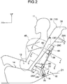
- a rear seat 12 at which the vehicle rear side airbag device fixing structure 10 according to the present exemplary embodiment is employed is provided with a rear seat cushion 14 that supports the buttock area and thigh area of an occupant 11 and a rear seatback 16 that supports the pelvis area and back area of the occupant 11.
- a headrest is provided at an upper end portion of the rear seatback 16.
- a child seat fixing member 18 is provided at the lower side of a lower end portion of the rear seatback 16.
- the child seat fixing member 18 conforms to the ISOFix standards (standards on sizes and attachment methods of fixing devices which have been unified by the International Organisation of Standardisation).
- the child seat fixing member 18 is formed of a high-strength pipe member, and is disposed in a state in which a length direction thereof runs along the vehicle width direction.
- Mounting brackets 20 are fixed by welding or the like at each of two length direction end portions and a length direction middle portion of the child seat fixing member 18.
- the mounting brackets 20 are fixed by fastening with nuts and bolts to a rear floor 21 of the vehicle body (see Fig. 2 ).
- strikers 22 which serve as fixing portions for compliance with the ISOFix standards, are attached in advance, by welding or the like, at predetermined positions in the length direction of the child seat fixing member 18 (sets of two locations between neighboring mounting brackets 20).
- the strikers 22 are formed in substantial "U" shapes of which opening portions open toward the vehicle rearward side in plan view.
- the strikers 22 are engaged with long, narrow fixing devices that are provided at lower end portions of child seats, which are not shown in the drawings.
- the child seat fixing member 18 supports the load toward the vehicle forward side and blocks movement of the child seat to the vehicle forward side.
- the aforementioned rear seatback 16 is a rear seatback of a divided collapsible type, including a pair of left and right main body portions 24 and a pair of left and right side seat portions 26.
- the main body portions 24 are tiltable relative to the rear floor 21, and the side seat portions 26 are disposed at vehicle width direction outer sides (vehicle door sides) relative to the main body portions 24.
- the pair of left and right main body portions 24 are each provided with a seat frame made of metal, which is not shown in the drawings. Lower end portions of these frames are joined, to be turnable about an axis along the vehicle width direction, to upper end portions of the mounting brackets 20. Thus, the rear seatback 16 is tiltable to the rear seat cushion 14 side thereof.
- the main body portions 24 are detachably joined to vehicle body side structural members by locking mechanisms (not shown in the drawings) provided at the rear side of each of two side portions of the main body portions 24.
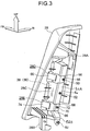
- the pair of left and right side seat portions 26 are each provided with a seat frame 28 made of resin (see Fig. 3 ).
- a hook portion 28A provided at an upper portion side of each seat frame 28 is hooked on a vehicle body side structural member, and a fastening portion 28B provided at the lower end side of the seat frame 28 is fixed by fastening to a vehicle body side structural member.
- the seat frame 28 is fixed to the vehicle body.
- a pad 30 formed of a foam body of urethane foam or the like is mounted at the vehicle forward side of the seat frame 28, and a surface of the pad 30 is covered with a cover 32.
- a seam portion 34 extending in the up-and-down direction is provided at the cover 32.
- An airbag module mounting portion 28C is provided at the above-described seat frame 28.
- the airbag module mounting portion 28C is formed in a substantially box-like shape, of which the vehicle forward side is open.
- An airbag module 38 that constitutes principal portions of a vehicle rear side airbag device 36 is mounted at the airbag module mounting portion 28C.
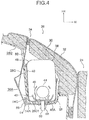
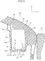
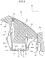
- the airbag module 38 is provided with a module case 40, a side airbag 42 (only a portion of which is shown in Fig. 4 to Fig. 6 ), a cylindrical inflator 44, and a diffuser 46.
- the module case 40 is fitted into the airbag module mounting portion 28C.
- the side airbag 42 is stowed in the module case 40 in a folded state.
- the inflator 44 is a gas generator that produces gas in the side airbag 42 when there is a side collision.
- the diffuser 46 is a flow regulator that encloses the inflator 44. For convenience of description, hatching is not shown in the cross-sections of some members in Fig. 4 to Fig. 6 .
- the module case 40 is formed in a substantial box-like shape that is vertically long, of which the vehicle forward side is open.
- a bottom wall portion 40A of the module case 40 is disposed in a state of abutting against a bottom wall 28C1 of the airbag module mounting portion 28C.
- the side airbag 42 is folded up by a predetermined folding method (bellows folding in the present exemplary embodiment), and a shape thereof is maintained by being covered with a wrapping material 48.
- the wrapping material 48 ruptures easily at a time of inflation and deployment of the side airbag 42.
- Common folding methods of an airbag are roll folding and bellows folding.
- the airbag is folded up by bellows folding, which is easy to unfold.
- the airbag may be folded by roll folding, and may be folded by a combination of roll folding and bellows folding.
- the inflator 44 and the diffuser 46 are disposed inside the folded side airbag 42. As shown in Fig. 2 , the inflator 44 is disposed with a length direction thereof along the up-and-down direction of the side seat portion 26, and plural gas emission holes are formed in one length direction end portion of the inflator 44 (in this case, the lower end portion). A squib, which is an ignition device, and an ignition agent are disposed in the other length direction end portion of the inflator 44 (in this case, the upper end portion).
- the squib is electrically connected to an airbag electronic control unit (ECU) that is disposed at the lower side of a console box or the like, and the airbag ECU is electrically connected to a side collision sensor disposed at a side portion of the vehicle body.
- ECU airbag electronic control unit
- the side collision sensor detects a side collision condition of the vehicle
- the side collision sensor outputs a detection signal to the airbag ECU.
- the airbag ECU makes a determination as to whether or not to activate the side airbag 42, and if a determination to activate the side airbag is made, a predetermined electric current is passed through the squib and the ignition agent is ignited. As a result, gas is emitted from the plural gas emission holes provided in the inflator 44.
- An inflator of a high-pressure gas enclosing type may be used instead of the inflator 44 of a gas-producing agent enclosing type.
- the above-described inflator 44 is covered by the diffuser 46, and is fixed to the diffuser 46 at locations which are not shown in the drawings.
- the diffuser 46 regulates flows of gas emitted from the inflator 44, and supplies the gas to the interior of the side airbag 42.
- a pair of upper and lower stud bolts 50 and 52 are provided at the diffuser 46.
- the upper side stud bolt 50 penetrates through the side airbag 42, the bottom wall portion 40A of the module case 40 and the bottom wall portion 28C 1 of the airbag module mounting portion 28C.
- the stud bolt 50 also penetrates through a metal plate 54 (a rigid member) superposed with a rear face of the bottom wall 28C1 and an anchoring fixture 56 superposed with a rear face of the metal plate 54.
- a distal end side of the stud bolt 50 is threaded into a nut 58.
- the upper portion side of the diffuser 46 is fixed by fastening to the module case 40, the metal plate 54 and the anchoring fixture 56, and to the seat frame 28.
- the side airbag 42 is sandwiched between the diffuser 46 and the bottom wall portion 40A of the module case 40.
- the airbag module 38 is fixed by fastening to the seat frame 28 at a height range in which the inflator 44 is disposed.
- the above-mentioned metal plate 54 is formed in a long, narrow shape along the up-and-down direction of the side seat portion 26.
- the metal plate 54 includes a frame reinforcement portion 54A and a bracket portion 54B (a projection portion).
- the frame reinforcement portion 54A has a linear shape in side view, substantially the whole of which, apart from a lower end portion thereof, is superposed with the bottom wall 28C1 of the airbag module mounting portion 28C.
- the bracket portion 54B is projected to the downward side of the frame reinforcement portion 54A.
- An upper portion side and an up-and-down direction middle portion of the frame reinforcement portion 54A are formed in "L" shapes in cross-section, being provided with a flanged portion 54C that is projected to the vehicle forward side from a vehicle width direction outer side end portion of the frame reinforcement portion 54A.
- the flanged portion 54C improves bending rigidness of the frame reinforcement portion 54A (the metal plate 54), and the airbag module mounting portion 28C is reinforced by the frame reinforcement portion 54A.
- the aforementioned anchoring fixture 56 is formed by a process of bending a plate made of metal into an "L" shape.
- a proximal end side of the anchoring fixture 56 is superposed with the frame reinforcement portion 54A and is fixed by fastening to the seat frame 28.
- a distal end side of the anchoring fixture 56 is projected to the vehicle forward side from the vehicle width direction outer side of the airbag module mounting portion 28C.
- the upper side webbing 60 is formed in a belt shape.
- the upper side webbing 60 is formed of a fabric that is more resistant to stretching than the cover 32.
- Portions of the upper side webbing 60 preceding and succeeding the insertion through the insertion hole 56A are superposed and sewn together.
- the one end side of the upper side webbing 60 is anchored at the anchoring fixture 56 and, via the anchoring fixture 56, is joined to (anchored at) the frame reinforcement portion 54A and the seat frame 28.
- the other end side of the upper side webbing 60 is inserted through an aperture 28D formed in the seat frame 28, and is sewn to the seam portion 34 provided at the cover 32. Therefore, when the side airbag 42 is inflating and deploying, the upper side webbing 60 is stretched by inflation pressure of the side airbag 42.
- the other end side of the upper side webbing 60 concentrates the inflation pressure of the side airbag 42 on the region of the seam portion 34 to which the other end side of the upper side webbing 60 is sewn, and the seam portion 34 is ruptured starting from this region.
- the lower side stud bolt 52 provided at the diffuser 46 penetrates through the side airbag 42 and the bottom wall portion 40A of the module case 40, and a distal end side of the stud bolt 52 is threaded into a nut 62.
- the lower portion side of the diffuser 46 is fixed by fastening to the module case 40, and the side airbag 42 is sandwiched between the diffuser 46 and the bottom wall portion 40A of the module case 40.
- Penetration holes with larger diameters than the nut 62 are formed in the bottom wall 28C1 of the airbag module mounting portion 28C and the frame reinforcement portion 54A.
- the nut 62 and the stud bolt 52 are disposed in a state of not being in contact with the bottom wall 28C1 and the frame reinforcement portion 54A.
- a nut 72 is threaded onto a distal end side of a bolt 70.
- the bolt 70 penetrates through the bottom wall portion 40A of the module case 40, the bottom wall 28C1 of the airbag module mounting portion 28C, the frame reinforcement portion 54A, and anchoring fixtures 66 and 68.
- the module case 40 is fixed by fastening to the upper end portion of the frame reinforcement portion 54A and the anchoring fixtures 66 and 68, and to the seat frame 28.
- the lower portion side of the frame reinforcement portion 54A is formed in an open cross-section shape (a substantial "U" shape in cross section) of which the vehicle forward side is open.
- the lower portion side of the frame reinforcement portion 54A is provided with a flanged portion 54D that is projected to the vehicle forward side from the vehicle width direction inner side of the frame reinforcement portion 54A. Rigidness of the frame reinforcement portion 54A with respect to loads in the vehicle front-and-rear direction is improved by the flanged portion 54D and the flanged portion 54C.
- the above-mentioned anchoring fixtures 66 and 68 are formed by processes of bending plates made of metal into "L" shapes. A proximal end side of the anchoring fixture 66 is superposed with the frame reinforcement portion 54A. In a state in which a proximal end side of the anchoring fixture 68 is superposed with the proximal end side of the anchoring fixture 66, the proximal end sides of the anchoring fixtures 66 and 68 are fixed by fastening to the frame reinforcement portion 54A and the seat frame 28.
- the distal end side of the anchoring fixture 66 is projected to the vehicle forward side from the vehicle width direction outer side of the airbag module mounting portion 28C
- the distal end side of the anchoring fixture 68 is projected to the vehicle forward side from the vehicle width direction inner side of the airbag module mounting portion 28C.
- Insertion holes 66A and 68A are formed in the distal end sides of the anchoring fixtures 66 and 68.
- One end sides of lower side webbings 74 and 76 which are formed in belt shapes, are inserted through the insertion holes 66A and 68A.
- the lower side webbings 74 and 76 are formed of the fabric that is more resistant to stretching than the cover 32.
- Portions of the lower side webbings 74 and 76 preceding and succeeding the insertions through the insertion holes 66A and 68A are superposed and sewn together.
- the one end sides of the lower side webbings 74 and 76 are anchored at the anchoring fixtures 66 and 68 and, via the anchoring fixtures 66 and 68, are joined to (anchored at) the frame reinforcement portion 54A and the seat frame 28.
- the other end side of the anchoring fixture 66 is inserted through an aperture 28E formed in the seat frame 28, and is sewn to the seam portion 34 provided at the cover 32.
- the other end side of the anchoring fixture 68 is projected between the pad 30 and the cover 32 to the seam portion 34 side, and is sewn to the seam portion 34.
- the lower side webbings 74 and 76 are stretched by inflation pressure of the side airbag 42.
- the other end sides of the lower side webbings 74 and 76 concentrate the inflation pressure of the side airbag 42 on the region of the seam portion 34 to which the other end sides of the lower side webbings 74 and 76 are sewn, and the seam portion 34 is ruptured starting from this region.
- bracket portion 54B is projected integrally from the lower end of the frame reinforcement portion 54A diagonally to the vehicle rearward side and downward side.
- the bracket portion 54B is formed in an open cross-section shape (a substantial "U" shape in cross section) of which the vehicle forward side is open, and rigidness of the bracket portion 54B with respect to loads in the vehicle front-and-rear direction is improved by the flanged portions 54C and 54D.
- a constitution is possible in which the bracket portion 54B and frame reinforcement portion 54A are formed as separate bodies and joined together by welding or the like.
- the lower portion side of the bracket portion 54B is inflected to the vehicle forward side relative to the upper portion side thereof.
- a lower end portion of the bracket portion 54B is disposed at the vehicle forward side relative to a length direction end portion (the vehicle width direction outer side end portion) of the child seat fixing member 18.
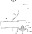
- a fastening fixture 78 formed in an open cross-section shape (a substantial "U" shape in cross-section), of which the vehicle rearward side is open, is attached by welding or the like to each of two length direction end portions of the pipe member structuring the child seat fixing member 18. As shown in Fig.
- a welded nut 80 is attached to the fastening fixture 78, and the lower end portion of the bracket portion 54B is fixed by fastening to the fastening fixture 78, by a bolt 82 threaded onto the welded nut 80.
- the lower end portion of the airbag module 38 is fixed by fastening to the child seat fixing member 18 via the metal plate 54.
- the side collision sensor if the vehicle has a side collision, the side collision sensor outputs a detection signal to the airbag ECU, and the airbag ECU activates the inflator 44.
- the inflator 44 activates, gas is produced inside the side airbag 42, and the side airbag 42 inflates.
- the inflation pressure of the side airbag 42 acts on the seam portion 34 of the cover 32 of the side seat portion 26, via the upper side webbing 60 and the lower side webbings 74 and 76, and the seam portion 34 ruptures.
- an opening is formed in the front face side of the side seat portion 26, and the side airbag 42 inflates and deploys through this opening to sideward of the occupant 11 (between the occupant 11 and a door, which is not shown in the drawings).
- the side airbag 42 protects the occupant 11 from from an impact during the side collision.
- the airbag module 38 is fixed by fastening, via the metal plate 54, to the child seat fixing member 18 conforming to the ISOFix standards. Because the child seat fixing member 18 is fixed to the rear floor 21 of the vehicle body at the downward side of the rear seatback 16 that is close to the pelvis area of the occupant 11, the airbag module 38 may be disposed to the occupant 11 side (vehicle width direction inner side) in comparison with a structure in which an airbag module is fixed to a rear wheel housing via a bracket. Moreover, because the child seat fixing member 18 exhibits a high rigidness with respect to a side collision of the vehicle, fixing portions of the airbag module 38 are resistant to being deformed during a side collision of the vehicle. Therefore, a long duration from when the side collision occurs until the attitude of the airbag module 38 changes may be assured, and consequently a margin of time for the side airbag 42 to be deployed in may be assured.
- the rear seatback 16 includes the main body portions 24, which are tiltable relative to the vehicle body, and the side seat portions 26 that are disposed at the vehicle width direction outer sides relative to the main body portions 24, and the airbag module 38 is disposed inside each side seat portion 26. Because each side seat portion 26 is fixed to the vehicle body, when the main body portions 24 of the rear seatback 16 are tilted relative to the vehicle body, the airbag module 38 is not displaced relative to the vehicle body. Thus, the airbag module 38 may be retained in a static state (a fixed state) relative to the vehicle body. Therefore, damage to the airbag module 38, a wire harness connected thereto or the like may be prevented.
- the lower end portion of the airbag module 38 is fixed by fastening to the child seat fixing member 18 via the metal plate 54.
- the support rigidness of the lower end portion of the airbag module 38 that is disposed close to the pelvis area of the occupant 11 may be excellently assured. Therefore, a reaction force when the lower portion side of the side airbag 42 is inflating and deploying to sideward of the pelvis area of the occupant 11 may be excellently supported.
- the airbag module 38 is fixed by fastening to the seat frame 28 made of resin that is provided at the side seat portion 26 at a height range in which the inflator 44 is disposed.
- a reaction force from the side airbag 42 being inflated and deployed by the gas produced by the inflator 44 may be excellently supported by the seat frame 28 made of resin.
- the airbag module 38 is fixed by fastening both to the frame reinforcement portion 54A of the metal plate 54 that is superposed with the seat frame 28 made of resin and to the seat frame 28.
- the seat frame 28 made of resin may be reinforced by the metal plate 54.
- the bracket portion 54B provided at the metal plate 54 is fixed by fastening to the child seat fixing member 18, the seat frame 28 may be excellently supported, and therefore a support rigidness of the airbag module 38 that is fixed by fastening to the metal plate 54 and the seat frame 28 made of resin may be improved.
- the one end sides of the upper side webbing 60 and the lower side webbings 74 and 76 which transfer the inflation pressure of the side airbag 42 to the seam portion 34 of the cover 32 of the side seat portion 26, are joined to the metal plate 54 that is fixed by fastening to the child seat fixing member 18. Therefore, the inflation pressure of the side airbag 42 acting on the upper side webbing 60 and the lower side webbings 74 and 76 may be excellently supported by the metal plate 54.
- the anchoring fixtures 66 and 68 at which the one end sides of the lower side webbings 74 and 76 are anchored are fixed by fastening both to the metal plate 54 and to the airbag module 38, and the anchoring fixture 56 at which the one end side of the upper side webbing 60 is anchored is fixed by fastening both to the metal plate 54 and to the airbag module 38. Therefore, the rigidness of these fastening-fixing portions may be improved.
- the bracket portion 54B that is projected to the downward side from the metal plate 54 and is fixed by fastening to the child seat fixing member 18 is formed in an open cross-section shape of which the vehicle forward side is open. Therefore, the metal plate 54 may be reduced in weight while the rigidness of the bracket portion 54B (and the metal plate 54) with respect to loads in the vehicle front-and-rear direction is assured.
- the fastening fixture 78 for fastening-fixing the bracket portion 54B is attached to the pipe member structuring the child seat fixing member 18. Therefore, the metal plate 54 may be fixed by fastening to the child seat fixing member 18 easily.
- the exemplary embodiment described above has a constitution in which the child seat fixing member 18 is equipped with the fastening fixture 78.
- the inventions according to claims 1 to 8 are not limited thus.
- a structure for fixing the metal plate 54 to the child seat fixing member 18 may be suitably modified.
- the exemplary embodiment described above has a constitution in which a fastening portion of the metal plate 54 to the child seat fixing member 18 is disposed at the vehicle width direction outer side relative to the mounting brackets 20.
- this is not limiting and a constitution is possible in which a fastening portion is disposed at a vehicle width direction inner side relative to the mounting brackets 20.
- the exemplary embodiment described above has a constitution in which the bracket portion 54B of the metal plate 54 is projected to the downward side from the airbag module 38 side.
- the inventions according to claims 1 to 7 are not limited thus.
- the position and shape of the bracket portion 54B may be suitably modified.
- the exemplary embodiment described above has a constitution in which the anchoring fixtures 56, 66 and 68, at which the one end sides of the upper side webbing 60 and the lower side webbings 74 and 76 are anchored, are fixed by fastening both to the metal plate 54 and to the airbag module 38 and the like.
- the inventions according to claims 1 to 6 are not limited thus.
- a constitution is possible in which the anchoring fixtures 56, 66 and 68 are fixed by fastening to the airbag module 38 and the like separately from the metal plate 54.
- the exemplary embodiment described above has a constitution in which the lower side webbings 74 and 76 and the upper side webbing 60 are provided.
- the inventions according to claims 1 to 5 are not limited thus. A constitution is possible in which these webbings are omitted.
- the exemplary embodiment described above has a constitution in which the metal plate 54 is integrally provided with the frame reinforcement portion 54A and the bracket portion 54B.
- the inventions according to claims 1 to 4 are not limited thus.
- a constitution is possible in which the bracket portion 54B or the whole of the metal plate 54 is omitted, and the module case 40 of the airbag module 38 is extended to the downward side and fixed to the child seat fixing member 18.
- a constitution is also possible in which a portion of the metal plate 54 at the upward side relative to the portion of fastening-fixing to the airbag module 38 by the bolt 70 and nut 72 (the upper portion side and the up-and-down direction middle portion of the frame reinforcement portion 54A) is omitted from the metal plate 54.
- a further constitution is possible in which the frame reinforcement portion 54A and the bracket portion 54B are divided and separately fixed to the airbag module 38. Further, the airbag module 38 may be fixed to a metal plate (rigid member) that is welded to the child seat fixing member 18.
- the exemplary embodiment described above has a constitution in which the metal plate 54 serves as the rigid member.
- the inventions according to claims 1 to 9 are not limited thus.
- a constitution is possible in which the rigid member is formed of a non-metal material that exhibits a high rigidness with respect to a side collision of the vehicle.
- the exemplary embodiment described above has a constitution in which the airbag module 38 is fixed by fastening to the seat frame 28 at the height region in which the inflator 44 is disposed.
- the inventions according to claims 1 to 3 are not limited thus.
- the position of a fastening portion of the airbag module 38 to the seat frame 28 may be suitably modified.
- the exemplary embodiment described above has a constitution in which the side seat portion 26 is provided with the seat frame 28 made of resin.
- the inventions according to claims 1 to 3 are not limited thus.
- a constitution is possible in which the seat frame of the side seat portion is made of metal.
- the exemplary embodiment described above has a constitution in which the lower end portion of the airbag module 38 is fixed by fastening to the child seat fixing member 18 via the metal plate 54 (the rigid member).
- the inventions according to claim 1 and claim 2 are not limited thus.
- a constitution is possible in which a portion other than a lower end portion of an airbag module is fixed by fastening to the child seat fixing member via the rigid member.
- a method of fixing the rigid member to the child seat fixing member is not limited to fixing by fastening and may be welding and the like.
- the exemplary embodiment described above has a constitution in which the rear seatback 16 is collapsible and the airbag modules 38 are disposed in the side seat portions 26.
- the invention according to claim 1 is not limited thus.
- the structure of the rear seat and the positions of airbag modules may be suitably modified.
- the exemplary embodiment described above has a constitution in which the child seat fixing member 18 is fixed to the rear floor 21 of the vehicle body.
- the invention according to claim 1 is not limited thus.
- a constitution is possible in which, if the rear seat is movable in the vehicle front-and-rear direction, the child seat fixing member is fixed to the seat frame of a rear seat cushion.
Landscapes
- Engineering & Computer Science (AREA)
- Mechanical Engineering (AREA)
- Aviation & Aerospace Engineering (AREA)
- Transportation (AREA)
- Health & Medical Sciences (AREA)
- Child & Adolescent Psychology (AREA)
- General Health & Medical Sciences (AREA)
- Air Bags (AREA)
- Seats For Vehicles (AREA)
Claims (9)
- Befestigungsstruktur (10) einer Fahrzeugrückseiten-Airbageinrichtung mit:einer Rücksitzlehne (16) eines Rücksitzes (12) eines Fahrzeugs;einem Kindersitzbefestigungsbauteil (18) mit einer gestreckten Form, das an einer nach unten gerichteten Seite der Rücksitzlehne (16) angeordnet ist, wobei eine Längsrichtung des Kindersitzbefestigungsbauteils (18) in einer Fahrzeugquerrichtung ist, wobei das Kindersitzbefestigungsbauteil (18) an einer Fahrzeugkarosserie oder an einem Sitzrahmen (28) befestigt ist, und wobei das Kindersitzbefestigungsbauteil (18) mit einem Befestigungsabschnitt (22) für eine Kindersitzbefestigung versehen ist; undeiner Fahrzeugrückseiten-Airbageinrichtung (36), die ein Airbag-Modul (38) umfasst, das an dem Kindersitzbefestigungsbauteil (18) direkt oder durch ein starres Bauteil (54) befestigt ist, das ein von dem Sitzrahmen (28) separates Teil ist, wobei im Fall einer Seitenkollision des Fahrzeugs ein in dem Airbag-Modul (38) vorgesehener Seitenairbag (42) aufgeblasen und seitwärts eines auf dem Rücksitz (12) sitzenden Insassen entfaltet wird.
- Befestigungsstruktur (10) einer Fahrzeugrückseiten-Airbageinrichtung nach Anspruch 1, wobei die Rücksitzlehne (16) folgendes umfasst:einen Hauptkörperabschnitt (24), der relativ zu der Fahrzeugkarosserie um seinen unteren Endabschnitt kippbar ist; undeinen Seitensitzabschnitt (26), der relativ zu dem Hauptkörperabschnitt (24) an einer in der Fahrzeugquerrichtung äußeren Seite angeordnet und an der Fahrzeugkarosserie befestigt ist,und wobei das Airbag-Modul (38) in dem Seitensitzabschnitt (26) angeordnet ist.
- Befestigungsstruktur (10) einer Fahrzeugrückseiten-Airbageinrichtung nach Anspruch 2, wobei der Seitensitzabschnitt (26) einen aus Harz gefertigten Sitzrahmen (28) umfasst, wobei das Airbag-Modul (38) einen Gasgenerator (44) umfasst, der den Seitenairbag (42) durch das Erzeugen von Gas innerhalb des Seitenairbags (42) aufbläst und entfaltet, und wobei das Airbag-Modul (38) durch das Festmachen an dem Sitzrahmen (28) in einem Höhenbereich befestigt ist, in dem der Gasgenerator (44) angeordnet ist.
- Befestigungsstruktur (10) einer Fahrzeugrückseiten-Airbageinrichtung nach einem der Ansprüche 1 bis 3, wobei ein unterer Endabschnitt des Airbag-Moduls (38) direkt oder durch das starre Bauteil (54) an dem Kindersitzbefestigungsbauteil (18) befestigt ist.
- Befestigungsstruktur (10) einer Fahrzeugrückseiten-Airbageinrichtung nach Anspruch 4, wobei das starre Bauteil (54) mit dem Sitzrahmen (28) übereinanderliegend ist, wobei das Airbag-Modul (38) durch das Festmachen sowohl an dem starren Bauteil (54) als auch an dem Sitzrahmen (28) befestigt ist, und wobei eine untere Endseite des starren Bauteils (54) an dem Kindersitzbefestigungsbauteil (18) befestigt ist.
- Befestigungsstruktur (10) einer Fahrzeugrückseiten-Airbageinrichtung nach einem der Ansprüche 1 bis 5, wobei:das Airbag-Modul (38) an dem Kindersitzbefestigungsbauteil (18) durch das starre Bauteil (54) befestigt ist;die Fahrzeugrückseiten-Airbageinrichtung (36) ein Gewebeband (60, 74, 76) umfasst, von dem eine Endseite mit dem starren Bauteil (54) verbunden ist und eine andere Endseite an einem Nahtabschnitt (34) eines Bezugs (32) der Rücksitzlehne (16) angeheftet ist; undeine Öffnung für das Gestatten des Aufblasens und Entfaltens des Seitenairbags (42) in der Rücksitzlehne (16) durch den Nahtabschnitt (34) ausgebildet ist, die durch einen über das Gewebeband (60, 74, 76) auf den Nahtabschnitt (34) wirkenden Aufblasdruck des Seitenairbags (42) aufgerissen wird.
- Befestigungsstruktur (10) einer Fahrzeugrückseiten-Airbageinrichtung nach Anspruch 6, wobei die eine Endseite des Gewebebands (60, 74, 76) an einer Verankerungshalterung (66, 68) verankert ist, die durch das Festmachen sowohl an dem starren Bauteil (54) als auch an dem Airbag-Modul (38) befestigt ist.
- Befestigungsstruktur (10) einer Fahrzeugrückseiten-Airbageinrichtung nach einem der Ansprüche 1 bis 7, wobei ein Vorsprungabschnitt (54B) des starren Bauteils (54) zu der nach unten gerichteten Seite von der Seite des Airbag-Moduls (38) vorsteht, wobei der Vorsprungabschnitt (54B) an dem Kindersitzbefestigungsbauteil (18) befestigt ist, und wobei der Vorsprungabschnitt (54B) in einer offenen Querschnittsform ausgebildet ist, deren eine Seite in einer Vorwärts-und- Rückwärts-Richtung des Fahrzeugs offen ist.
- Befestigungsstruktur (10) einer Fahrzeugrückseiten-Airbageinrichtung nach einem der Ansprüche 1 bis 8, wobei das Kindersitzbefestigungsbauteil (18) aus einem Rohrbauteil ausgebildet ist, und wobei das starre Bauteil (54) durch das Festmachen an einer an dem Rohrbauteil befestigten Halterung zum Festmachen befestigt ist.
Applications Claiming Priority (1)
| Application Number | Priority Date | Filing Date | Title |
|---|---|---|---|
| PCT/JP2010/065868 WO2012035619A1 (ja) | 2010-09-14 | 2010-09-14 | 車両用リヤサイドエアバッグ装置の固定構造 |
Publications (3)
| Publication Number | Publication Date |
|---|---|
| EP2617606A1 EP2617606A1 (de) | 2013-07-24 |
| EP2617606A4 EP2617606A4 (de) | 2014-12-31 |
| EP2617606B1 true EP2617606B1 (de) | 2016-04-27 |
Family
ID=45831121
Family Applications (1)
| Application Number | Title | Priority Date | Filing Date |
|---|---|---|---|
| EP10857253.8A Not-in-force EP2617606B1 (de) | 2010-09-14 | 2010-09-14 | Verankerungsstruktur eines hinteren seitenairbags eines fahrzeuges |
Country Status (5)
| Country | Link |
|---|---|
| US (1) | US8752861B2 (de) |
| EP (1) | EP2617606B1 (de) |
| JP (1) | JP5408360B2 (de) |
| CN (1) | CN103108781B (de) |
| WO (1) | WO2012035619A1 (de) |
Families Citing this family (51)
| Publication number | Priority date | Publication date | Assignee | Title |
|---|---|---|---|---|
| US9085279B2 (en) * | 2010-11-17 | 2015-07-21 | Toyota Jidosha Kabushiki Kaisha | Side airbag device for vehicle |
| JP5859351B2 (ja) * | 2012-03-19 | 2016-02-10 | テイ・エス テック株式会社 | モジュールホルダ |
| JP6235202B2 (ja) * | 2012-09-28 | 2017-11-22 | テイ・エス テック株式会社 | 車両用のシート及びエアバッグケース |
| JP5798146B2 (ja) * | 2013-04-19 | 2015-10-21 | テイ・エス テック株式会社 | サイドエアバッグ装置 |
| EP2987683B1 (de) * | 2013-04-19 | 2017-07-26 | TS Tech Co., Ltd. | Seitenairbagvorrichtung |
| JP6141672B2 (ja) * | 2013-04-19 | 2017-06-07 | テイ・エス テック株式会社 | サイドエアバッグ装置 |
| DE102013225053A1 (de) * | 2013-12-05 | 2015-06-11 | Autoliv Development Ab | Airbagmodul |
| JP6272179B2 (ja) * | 2014-08-06 | 2018-01-31 | テイ・エス テック株式会社 | サイドエアバッグ装置 |
| JP6388802B2 (ja) * | 2014-07-14 | 2018-09-12 | テイ・エス テック株式会社 | サイドエアバッグ装置 |
| JP6495588B2 (ja) * | 2014-07-14 | 2019-04-03 | テイ・エス テック株式会社 | サイドエアバッグ装置 |
| JP6155232B2 (ja) * | 2014-07-14 | 2017-06-28 | 本田技研工業株式会社 | エアバッグ装置の車体取付構造 |
| JP6348593B2 (ja) * | 2014-07-14 | 2018-06-27 | テイ・エス テック株式会社 | サイドエアバッグ装置 |
| US10059297B2 (en) | 2014-07-14 | 2018-08-28 | Ts Tech Co., Ltd. | Side air bag device |
| WO2016010010A1 (ja) * | 2014-07-14 | 2016-01-21 | テイ・エス テック株式会社 | サイドエアバッグ装置 |
| JP6396101B2 (ja) * | 2014-07-14 | 2018-09-26 | テイ・エス テック株式会社 | サイドエアバッグ装置 |
| JP6272180B2 (ja) * | 2014-08-06 | 2018-01-31 | テイ・エス テック株式会社 | サイドエアバッグ装置 |
| US10449926B2 (en) | 2014-08-06 | 2019-10-22 | Ts Tech Co., Ltd. | Seatbelt assist device and vehicle seat |
| WO2016021622A1 (ja) | 2014-08-06 | 2016-02-11 | テイ・エス テック株式会社 | シートベルトアシスト装置及び乗り物用シート |
| JP6292103B2 (ja) * | 2014-11-14 | 2018-03-14 | トヨタ紡織株式会社 | 乗物用シート |
| JP6417932B2 (ja) * | 2014-12-25 | 2018-11-07 | 豊田合成株式会社 | サイドエアバッグ装置 |
| JP6462515B2 (ja) * | 2015-07-21 | 2019-01-30 | 株式会社イノアックコーポレーション | シートバックサイド及びシートバックサイド用基材 |
| WO2017022678A1 (ja) * | 2015-08-06 | 2017-02-09 | テイ・エス テック株式会社 | サイドエアバッグ装置 |
| JP6219347B2 (ja) * | 2015-08-20 | 2017-10-25 | テイ・エス テック株式会社 | サイドエアバッグ装置 |
| JP6571459B2 (ja) | 2015-09-04 | 2019-09-04 | トヨタ自動車株式会社 | 後席用サイドエアバッグ装置 |
| JP6299710B2 (ja) * | 2015-09-04 | 2018-03-28 | トヨタ自動車株式会社 | 後席用サイドエアバッグ装置 |
| DE202016105511U1 (de) * | 2016-10-05 | 2017-01-30 | Lear Corporation | Airbagsystem für ein Fahrzeug |
| FR3045536B1 (fr) * | 2015-12-17 | 2019-05-24 | Psa Automobiles Sa. | Dispositif de garnissage a airbag integre, pour un vehicule |
| JP6646146B2 (ja) * | 2016-06-01 | 2020-02-14 | オートリブ ディベロップメント エービー | 乗員保護装置 |
| CN107640073B (zh) * | 2016-07-14 | 2019-10-01 | 本田技研工业(中国)投资有限公司 | 车辆用座椅结构 |
| JP6328820B2 (ja) * | 2017-05-08 | 2018-05-23 | テイ・エス テック株式会社 | サイドエアバッグ装置 |
| JP6438535B1 (ja) | 2017-06-28 | 2018-12-12 | 日本発條株式会社 | 車両用シート、及び力布の縫製方法 |
| JP6993566B2 (ja) * | 2017-08-04 | 2022-02-15 | テイ・エス テック株式会社 | 車両用シート |
| JP6866826B2 (ja) * | 2017-11-09 | 2021-04-28 | トヨタ自動車株式会社 | 後席サイドエアバッグ装置 |
| EP3708422B1 (de) * | 2017-11-09 | 2022-02-09 | TS Tech Co., Ltd. | Seitenairbagvorrichtung und verfahren zu ihrer herstellung |
| CN111315618B (zh) | 2017-11-09 | 2022-07-12 | 提爱思科技股份有限公司 | 侧安全气囊装置 |
| EP3584122B1 (de) * | 2018-01-26 | 2021-11-17 | Autoliv Development AB | Seitenairbagvorrichtung |
| JP6569756B2 (ja) * | 2018-03-08 | 2019-09-04 | テイ・エス テック株式会社 | 車両用シート |
| JP7203501B2 (ja) * | 2018-03-13 | 2023-01-13 | テイ・エス テック株式会社 | サイドエアバッグ装置 |
| JP7032187B2 (ja) * | 2018-03-13 | 2022-03-08 | テイ・エス テック株式会社 | サイドエアバッグ装置 |
| CN116176480B (zh) | 2018-03-13 | 2025-08-05 | 提爱思科技股份有限公司 | 侧边安全气囊装置 |
| WO2019194197A1 (ja) * | 2018-04-05 | 2019-10-10 | テイ・エス テック株式会社 | 乗物用シート |
| FR3089174B1 (fr) * | 2018-11-29 | 2022-08-05 | Psa Automobiles Sa | Système de fixation de module de coussin gonflable de sécurité anti-rotation |
| FR3089173B1 (fr) * | 2018-11-29 | 2020-11-13 | Psa Automobiles Sa | Système de fixation de module de coussin gonflable de sécurité avec une patte anti-rotation |
| JP7115411B2 (ja) * | 2019-04-23 | 2022-08-09 | 豊田合成株式会社 | 膝保護用エアバッグ装置 |
| JP7311753B2 (ja) * | 2019-05-20 | 2023-07-20 | テイ・エス テック株式会社 | サイドエアバッグ装置 |
| JP7249888B2 (ja) * | 2019-06-12 | 2023-03-31 | 株式会社タチエス | 乗物用シートのサイドサポートブロック |
| JP7124810B2 (ja) * | 2019-08-26 | 2022-08-24 | 豊田合成株式会社 | サイドエアバッグ装置 |
| EP4119402A4 (de) * | 2020-03-12 | 2024-04-24 | Autoliv Development AB | Seitenairbagvorrichtung |
| JP7469618B2 (ja) | 2020-03-19 | 2024-04-17 | テイ・エス テック株式会社 | 乗り物用シート |
| FR3129334B1 (fr) * | 2021-11-19 | 2026-04-24 | Faurecia Sieges Dautomobile | Dossier de siège de véhicule muni d’un dispositif de coussin gonflable de sécurité et procédé d’assemblage d’un tel dossier |
| JP7903328B2 (ja) * | 2022-10-18 | 2026-08-12 | トヨタ紡織株式会社 | シートバック |
Family Cites Families (34)
| Publication number | Priority date | Publication date | Assignee | Title |
|---|---|---|---|---|
| DE19515851C2 (de) | 1994-05-21 | 2003-03-06 | Volkswagen Ag | Sicherheitseinrichtung für ein Fahrzeug |
| US5601332A (en) * | 1995-01-30 | 1997-02-11 | Hoover Universal, Inc. | Replaceable seat booster with an inflatable air cushion module |
| JP3141747B2 (ja) * | 1995-09-18 | 2001-03-05 | トヨタ自動車株式会社 | 側突用エアバッグ装置を備えたシート構造 |
| US5947630A (en) * | 1996-11-08 | 1999-09-07 | Breed Automotive Technology, Inc. | Side air bag module attachment |
| DE19650087C1 (de) * | 1996-12-03 | 1997-12-04 | Faure Bertrand Sitztech Gmbh | Vorrichtung zur lösbaren Befestigung von Gegenständen, insbesondere von Kindersitzen, an einem Fahrzeugsitz mit klappbarer Rückenlehne |
| JP3548756B2 (ja) | 1997-09-19 | 2004-07-28 | 日産自動車株式会社 | 自動車の側突用エアバッグ装置 |
| WO2000005101A1 (en) * | 1998-07-21 | 2000-02-03 | Johnson Controls Technology Company | Cargo retention system |
| US6030046A (en) * | 1998-10-20 | 2000-02-29 | Chrysler Corporation | Apparatus for anchoring a child seat within a motor vehicle |
| US7040696B2 (en) * | 1998-10-30 | 2006-05-09 | Indiana Mills & Manufacturing, Inc. | System of seats for a vehicle |
| JP3478981B2 (ja) | 1998-12-25 | 2003-12-15 | 日本プラスト株式会社 | 自動車用サイドエアバッグ装置 |
| US6126192A (en) * | 1999-03-10 | 2000-10-03 | Autoliv Asp, Inc. | No fasteners side air bag module |
| JP2000343994A (ja) | 1999-06-02 | 2000-12-12 | Takashimaya Nippatsu Kogyo Co Ltd | 自動車用リヤシート |
| JP3909636B2 (ja) * | 1999-09-07 | 2007-04-25 | スズキ株式会社 | チャイルドシート固定構造 |
| US6279798B1 (en) * | 1999-11-10 | 2001-08-28 | Ford Global Tech., Inc. | Storage assembly |
| DE10018170B4 (de) * | 2000-04-12 | 2012-10-31 | Audi Ag | Luftsackanordnung |
| US6276754B1 (en) * | 2000-04-21 | 2001-08-21 | Lear Corporation | Child seat attachment assembly |
| JP2002036997A (ja) | 2000-07-21 | 2002-02-06 | Honda Motor Co Ltd | 側面衝突用エアバッグ装置 |
| JP4000439B2 (ja) | 2001-01-15 | 2007-10-31 | スズキ株式会社 | 子供用シートの固定構造 |
| DE10137824C2 (de) | 2001-08-02 | 2003-05-28 | Daimler Chrysler Ag | Insassenrückhaltesystem im Fondbereich eines Kraftfahrzeugs |
| US6634710B1 (en) * | 2001-09-28 | 2003-10-21 | Lear Corporation | Vehicle seat assembly having child seat attachments |
| EP1511659B1 (de) * | 2002-06-07 | 2005-10-26 | Autoliv Development Ab | Elektrisch isolierte befestigungsanordnung für ein airbagmodul |
| US6767057B2 (en) * | 2002-09-17 | 2004-07-27 | General Motors Corporation | Vehicle anchorage system for child seat |
| JP4248980B2 (ja) | 2003-09-18 | 2009-04-02 | 西川ゴム工業株式会社 | ベルトラインウェザーストリップ |
| JP4452598B2 (ja) * | 2004-10-08 | 2010-04-21 | 日本発條株式会社 | サイドエアバッグを備えたシート |
| JP4463700B2 (ja) * | 2005-01-25 | 2010-05-19 | 本田技研工業株式会社 | 車両用シート |
| JP4523881B2 (ja) * | 2005-06-28 | 2010-08-11 | 本田技研工業株式会社 | シートの組立方法 |
| US7296854B2 (en) * | 2005-11-17 | 2007-11-20 | Illinois Tool Works Inc | Safety seat restraint system |
| US7510227B2 (en) * | 2007-03-30 | 2009-03-31 | Toyota Motor Engineering & Manufacturing North America, Inc. | Vehicle rear seat |
| US7798519B2 (en) * | 2007-08-10 | 2010-09-21 | Toyoda Gosei Co., Ltd. | Side airbag device |
| JP2009040328A (ja) * | 2007-08-10 | 2009-02-26 | Toyoda Gosei Co Ltd | サイドエアバッグ装置 |
| JP2009113594A (ja) * | 2007-11-05 | 2009-05-28 | Toyota Motor Corp | 後席用サイドエアバッグ装置 |
| JP2010070080A (ja) * | 2008-09-19 | 2010-04-02 | Toyota Motor Corp | サイドエアバッグ装置 |
| JP2010100229A (ja) * | 2008-10-25 | 2010-05-06 | Tachi S Co Ltd | 自動車のリア・シートに用いるリア・シート・バック |
| JP5169864B2 (ja) * | 2009-01-22 | 2013-03-27 | トヨタ紡織株式会社 | 車両用シート |
-
2010
- 2010-09-14 EP EP10857253.8A patent/EP2617606B1/de not_active Not-in-force
- 2010-09-14 WO PCT/JP2010/065868 patent/WO2012035619A1/ja not_active Ceased
- 2010-09-14 JP JP2012533777A patent/JP5408360B2/ja active Active
- 2010-09-14 CN CN201080069073.6A patent/CN103108781B/zh not_active Expired - Fee Related
- 2010-09-14 US US13/821,680 patent/US8752861B2/en not_active Expired - Fee Related
Non-Patent Citations (1)
| Title |
|---|
| None * |
Also Published As
| Publication number | Publication date |
|---|---|
| WO2012035619A1 (ja) | 2012-03-22 |
| JP5408360B2 (ja) | 2014-02-05 |
| CN103108781A (zh) | 2013-05-15 |
| US8752861B2 (en) | 2014-06-17 |
| CN103108781B (zh) | 2015-06-03 |
| EP2617606A1 (de) | 2013-07-24 |
| US20130175792A1 (en) | 2013-07-11 |
| JPWO2012035619A1 (ja) | 2014-01-20 |
| EP2617606A4 (de) | 2014-12-31 |
Similar Documents
| Publication | Publication Date | Title |
|---|---|---|
| US8752861B2 (en) | Vehicle rear side airbag device fixing structure | |
| EP2631126B1 (de) | Seitenairbagvorrichtung für rücksitze | |
| US11077815B2 (en) | Vehicle seat equipped with side airbag device, and side airbag device | |
| JP5382199B2 (ja) | 車両用サイドエアバッグ装置 | |
| JP6455483B2 (ja) | 乗員保護装置 | |
| JP6565771B2 (ja) | 乗員保護装置 | |
| KR101738555B1 (ko) | 사이드 에어백 장치 | |
| EP3900985B1 (de) | Seitenairbagvorrichtung, damit ausgestatteter fahrzeugsitz und verfahren zur herstellung einer seitenairbagvorrichtung | |
| CN107531206A (zh) | 乘员保护装置 | |
| CN110053526B (zh) | 车辆用座椅 | |
| US11267433B2 (en) | Side airbag device and vehicle seat provided with same | |
| JP2024058412A (ja) | エアバッグ装置及び乗員保護装置 | |
| JP7696454B2 (ja) | 車両用サイドエアバッグ装置 | |
| US11358555B2 (en) | Vehicle seat | |
| JP7605083B2 (ja) | サイドエアバッグ装置を搭載した車両用シート | |
| JP7678280B2 (ja) | 車両用安全装置 | |
| KR20250099343A (ko) | 차량용 사이드 에어백 장치 | |
| CN114454842B (zh) | 车辆用侧面碰撞安全气囊系统 | |
| WO2024095697A1 (ja) | 乗員拘束装置 | |
| JP7780920B2 (ja) | ファーサイドエアバッグ装置 | |
| JP7605082B2 (ja) | サイドエアバッグ装置を搭載した車両用シート | |
| JP7348571B2 (ja) | サイドエアバッグ装置 | |
| CN114454843B (zh) | 车辆用侧面气囊 | |
| JP6032157B2 (ja) | 乗員拘束装置 | |
| WO2026070547A1 (ja) | 乗員保護装置と車両シート |
Legal Events
| Date | Code | Title | Description |
|---|---|---|---|
| PUAI | Public reference made under article 153(3) epc to a published international application that has entered the european phase |
Free format text: ORIGINAL CODE: 0009012 |
|
| 17P | Request for examination filed |
Effective date: 20130318 |
|
| AK | Designated contracting states |
Kind code of ref document: A1 Designated state(s): AL AT BE BG CH CY CZ DE DK EE ES FI FR GB GR HR HU IE IS IT LI LT LU LV MC MK MT NL NO PL PT RO SE SI SK SM TR |
|
| DAX | Request for extension of the european patent (deleted) | ||
| A4 | Supplementary search report drawn up and despatched |
Effective date: 20141201 |
|
| RIC1 | Information provided on ipc code assigned before grant |
Ipc: B60R 21/207 20060101AFI20141125BHEP Ipc: B60N 2/44 20060101ALI20141125BHEP Ipc: B60N 2/28 20060101ALI20141125BHEP Ipc: B60N 2/58 20060101ALI20141125BHEP |
|
| GRAP | Despatch of communication of intention to grant a patent |
Free format text: ORIGINAL CODE: EPIDOSNIGR1 |
|
| RIC1 | Information provided on ipc code assigned before grant |
Ipc: B60N 2/58 20060101ALI20150929BHEP Ipc: B60N 2/28 20060101ALI20150929BHEP Ipc: B60R 21/207 20060101AFI20150929BHEP Ipc: B60N 2/44 20060101ALI20150929BHEP |
|
| INTG | Intention to grant announced |
Effective date: 20151026 |
|
| GRAS | Grant fee paid |
Free format text: ORIGINAL CODE: EPIDOSNIGR3 |
|
| GRAR | Information related to intention to grant a patent recorded |
Free format text: ORIGINAL CODE: EPIDOSNIGR71 |
|
| GRAA | (expected) grant |
Free format text: ORIGINAL CODE: 0009210 |
|
| INTG | Intention to grant announced |
Effective date: 20160311 |
|
| AK | Designated contracting states |
Kind code of ref document: B1 Designated state(s): AL AT BE BG CH CY CZ DE DK EE ES FI FR GB GR HR HU IE IS IT LI LT LU LV MC MK MT NL NO PL PT RO SE SI SK SM TR |
|
| REG | Reference to a national code |
Ref country code: GB Ref legal event code: FG4D |
|
| REG | Reference to a national code |
Ref country code: CH Ref legal event code: EP |
|
| REG | Reference to a national code |
Ref country code: AT Ref legal event code: REF Ref document number: 794379 Country of ref document: AT Kind code of ref document: T Effective date: 20160515 |
|
| REG | Reference to a national code |
Ref country code: IE Ref legal event code: FG4D |
|
| REG | Reference to a national code |
Ref country code: DE Ref legal event code: R096 Ref document number: 602010032953 Country of ref document: DE |
|
| REG | Reference to a national code |
Ref country code: DE Ref legal event code: R084 Ref document number: 602010032953 Country of ref document: DE |
|
| REG | Reference to a national code |
Ref country code: LT Ref legal event code: MG4D |
|
| REG | Reference to a national code |
Ref country code: NL Ref legal event code: MP Effective date: 20160427 |
|
| REG | Reference to a national code |
Ref country code: AT Ref legal event code: MK05 Ref document number: 794379 Country of ref document: AT Kind code of ref document: T Effective date: 20160427 |
|
| PG25 | Lapsed in a contracting state [announced via postgrant information from national office to epo] |
Ref country code: NL Free format text: LAPSE BECAUSE OF FAILURE TO SUBMIT A TRANSLATION OF THE DESCRIPTION OR TO PAY THE FEE WITHIN THE PRESCRIBED TIME-LIMIT Effective date: 20160427 |
|
| PG25 | Lapsed in a contracting state [announced via postgrant information from national office to epo] |
Ref country code: PL Free format text: LAPSE BECAUSE OF FAILURE TO SUBMIT A TRANSLATION OF THE DESCRIPTION OR TO PAY THE FEE WITHIN THE PRESCRIBED TIME-LIMIT Effective date: 20160427 Ref country code: NO Free format text: LAPSE BECAUSE OF FAILURE TO SUBMIT A TRANSLATION OF THE DESCRIPTION OR TO PAY THE FEE WITHIN THE PRESCRIBED TIME-LIMIT Effective date: 20160727 Ref country code: LT Free format text: LAPSE BECAUSE OF FAILURE TO SUBMIT A TRANSLATION OF THE DESCRIPTION OR TO PAY THE FEE WITHIN THE PRESCRIBED TIME-LIMIT Effective date: 20160427 Ref country code: FI Free format text: LAPSE BECAUSE OF FAILURE TO SUBMIT A TRANSLATION OF THE DESCRIPTION OR TO PAY THE FEE WITHIN THE PRESCRIBED TIME-LIMIT Effective date: 20160427 |
|
| PG25 | Lapsed in a contracting state [announced via postgrant information from national office to epo] |
Ref country code: LV Free format text: LAPSE BECAUSE OF FAILURE TO SUBMIT A TRANSLATION OF THE DESCRIPTION OR TO PAY THE FEE WITHIN THE PRESCRIBED TIME-LIMIT Effective date: 20160427 Ref country code: GR Free format text: LAPSE BECAUSE OF FAILURE TO SUBMIT A TRANSLATION OF THE DESCRIPTION OR TO PAY THE FEE WITHIN THE PRESCRIBED TIME-LIMIT Effective date: 20160728 Ref country code: ES Free format text: LAPSE BECAUSE OF FAILURE TO SUBMIT A TRANSLATION OF THE DESCRIPTION OR TO PAY THE FEE WITHIN THE PRESCRIBED TIME-LIMIT Effective date: 20160427 Ref country code: HR Free format text: LAPSE BECAUSE OF FAILURE TO SUBMIT A TRANSLATION OF THE DESCRIPTION OR TO PAY THE FEE WITHIN THE PRESCRIBED TIME-LIMIT Effective date: 20160427 Ref country code: PT Free format text: LAPSE BECAUSE OF FAILURE TO SUBMIT A TRANSLATION OF THE DESCRIPTION OR TO PAY THE FEE WITHIN THE PRESCRIBED TIME-LIMIT Effective date: 20160829 Ref country code: AT Free format text: LAPSE BECAUSE OF FAILURE TO SUBMIT A TRANSLATION OF THE DESCRIPTION OR TO PAY THE FEE WITHIN THE PRESCRIBED TIME-LIMIT Effective date: 20160427 Ref country code: SE Free format text: LAPSE BECAUSE OF FAILURE TO SUBMIT A TRANSLATION OF THE DESCRIPTION OR TO PAY THE FEE WITHIN THE PRESCRIBED TIME-LIMIT Effective date: 20160427 |
|
| PG25 | Lapsed in a contracting state [announced via postgrant information from national office to epo] |
Ref country code: IT Free format text: LAPSE BECAUSE OF FAILURE TO SUBMIT A TRANSLATION OF THE DESCRIPTION OR TO PAY THE FEE WITHIN THE PRESCRIBED TIME-LIMIT Effective date: 20160427 Ref country code: BE Free format text: LAPSE BECAUSE OF FAILURE TO SUBMIT A TRANSLATION OF THE DESCRIPTION OR TO PAY THE FEE WITHIN THE PRESCRIBED TIME-LIMIT Effective date: 20160427 |
|
| REG | Reference to a national code |
Ref country code: DE Ref legal event code: R097 Ref document number: 602010032953 Country of ref document: DE |
|
| PG25 | Lapsed in a contracting state [announced via postgrant information from national office to epo] |
Ref country code: EE Free format text: LAPSE BECAUSE OF FAILURE TO SUBMIT A TRANSLATION OF THE DESCRIPTION OR TO PAY THE FEE WITHIN THE PRESCRIBED TIME-LIMIT Effective date: 20160427 Ref country code: RO Free format text: LAPSE BECAUSE OF FAILURE TO SUBMIT A TRANSLATION OF THE DESCRIPTION OR TO PAY THE FEE WITHIN THE PRESCRIBED TIME-LIMIT Effective date: 20160427 Ref country code: CZ Free format text: LAPSE BECAUSE OF FAILURE TO SUBMIT A TRANSLATION OF THE DESCRIPTION OR TO PAY THE FEE WITHIN THE PRESCRIBED TIME-LIMIT Effective date: 20160427 Ref country code: DK Free format text: LAPSE BECAUSE OF FAILURE TO SUBMIT A TRANSLATION OF THE DESCRIPTION OR TO PAY THE FEE WITHIN THE PRESCRIBED TIME-LIMIT Effective date: 20160427 Ref country code: SK Free format text: LAPSE BECAUSE OF FAILURE TO SUBMIT A TRANSLATION OF THE DESCRIPTION OR TO PAY THE FEE WITHIN THE PRESCRIBED TIME-LIMIT Effective date: 20160427 |
|
| PG25 | Lapsed in a contracting state [announced via postgrant information from national office to epo] |
Ref country code: SM Free format text: LAPSE BECAUSE OF FAILURE TO SUBMIT A TRANSLATION OF THE DESCRIPTION OR TO PAY THE FEE WITHIN THE PRESCRIBED TIME-LIMIT Effective date: 20160427 |
|
| PLBE | No opposition filed within time limit |
Free format text: ORIGINAL CODE: 0009261 |
|
| STAA | Information on the status of an ep patent application or granted ep patent |
Free format text: STATUS: NO OPPOSITION FILED WITHIN TIME LIMIT |
|
| 26N | No opposition filed |
Effective date: 20170130 |
|
| PG25 | Lapsed in a contracting state [announced via postgrant information from national office to epo] |
Ref country code: MC Free format text: LAPSE BECAUSE OF FAILURE TO SUBMIT A TRANSLATION OF THE DESCRIPTION OR TO PAY THE FEE WITHIN THE PRESCRIBED TIME-LIMIT Effective date: 20160427 |
|
| REG | Reference to a national code |
Ref country code: CH Ref legal event code: PL |
|
| GBPC | Gb: european patent ceased through non-payment of renewal fee |
Effective date: 20160914 |
|
| PG25 | Lapsed in a contracting state [announced via postgrant information from national office to epo] |
Ref country code: SI Free format text: LAPSE BECAUSE OF FAILURE TO SUBMIT A TRANSLATION OF THE DESCRIPTION OR TO PAY THE FEE WITHIN THE PRESCRIBED TIME-LIMIT Effective date: 20160427 |
|
| REG | Reference to a national code |
Ref country code: IE Ref legal event code: MM4A |
|
| REG | Reference to a national code |
Ref country code: FR Ref legal event code: ST Effective date: 20170531 |
|
| PG25 | Lapsed in a contracting state [announced via postgrant information from national office to epo] |
Ref country code: GB Free format text: LAPSE BECAUSE OF NON-PAYMENT OF DUE FEES Effective date: 20160914 Ref country code: FR Free format text: LAPSE BECAUSE OF NON-PAYMENT OF DUE FEES Effective date: 20160930 Ref country code: CH Free format text: LAPSE BECAUSE OF NON-PAYMENT OF DUE FEES Effective date: 20160930 Ref country code: LI Free format text: LAPSE BECAUSE OF NON-PAYMENT OF DUE FEES Effective date: 20160930 Ref country code: IE Free format text: LAPSE BECAUSE OF NON-PAYMENT OF DUE FEES Effective date: 20160914 |
|
| PG25 | Lapsed in a contracting state [announced via postgrant information from national office to epo] |
Ref country code: LU Free format text: LAPSE BECAUSE OF NON-PAYMENT OF DUE FEES Effective date: 20160914 |
|
| PG25 | Lapsed in a contracting state [announced via postgrant information from national office to epo] |
Ref country code: CY Free format text: LAPSE BECAUSE OF FAILURE TO SUBMIT A TRANSLATION OF THE DESCRIPTION OR TO PAY THE FEE WITHIN THE PRESCRIBED TIME-LIMIT Effective date: 20160427 Ref country code: HU Free format text: LAPSE BECAUSE OF FAILURE TO SUBMIT A TRANSLATION OF THE DESCRIPTION OR TO PAY THE FEE WITHIN THE PRESCRIBED TIME-LIMIT; INVALID AB INITIO Effective date: 20100914 |
|
| PG25 | Lapsed in a contracting state [announced via postgrant information from national office to epo] |
Ref country code: IS Free format text: LAPSE BECAUSE OF FAILURE TO SUBMIT A TRANSLATION OF THE DESCRIPTION OR TO PAY THE FEE WITHIN THE PRESCRIBED TIME-LIMIT Effective date: 20160427 Ref country code: TR Free format text: LAPSE BECAUSE OF FAILURE TO SUBMIT A TRANSLATION OF THE DESCRIPTION OR TO PAY THE FEE WITHIN THE PRESCRIBED TIME-LIMIT Effective date: 20160427 Ref country code: MK Free format text: LAPSE BECAUSE OF FAILURE TO SUBMIT A TRANSLATION OF THE DESCRIPTION OR TO PAY THE FEE WITHIN THE PRESCRIBED TIME-LIMIT Effective date: 20160427 Ref country code: MT Free format text: LAPSE BECAUSE OF NON-PAYMENT OF DUE FEES Effective date: 20160930 |
|
| PG25 | Lapsed in a contracting state [announced via postgrant information from national office to epo] |
Ref country code: BG Free format text: LAPSE BECAUSE OF FAILURE TO SUBMIT A TRANSLATION OF THE DESCRIPTION OR TO PAY THE FEE WITHIN THE PRESCRIBED TIME-LIMIT Effective date: 20160427 |
|
| PG25 | Lapsed in a contracting state [announced via postgrant information from national office to epo] |
Ref country code: AL Free format text: LAPSE BECAUSE OF FAILURE TO SUBMIT A TRANSLATION OF THE DESCRIPTION OR TO PAY THE FEE WITHIN THE PRESCRIBED TIME-LIMIT Effective date: 20160427 |
|
| PGFP | Annual fee paid to national office [announced via postgrant information from national office to epo] |
Ref country code: DE Payment date: 20210803 Year of fee payment: 12 |
|
| REG | Reference to a national code |
Ref country code: DE Ref legal event code: R119 Ref document number: 602010032953 Country of ref document: DE |
|
| PG25 | Lapsed in a contracting state [announced via postgrant information from national office to epo] |
Ref country code: DE Free format text: LAPSE BECAUSE OF NON-PAYMENT OF DUE FEES Effective date: 20230401 |