EP3900985B1 - Seitenairbagvorrichtung, damit ausgestatteter fahrzeugsitz und verfahren zur herstellung einer seitenairbagvorrichtung - Google Patents
Seitenairbagvorrichtung, damit ausgestatteter fahrzeugsitz und verfahren zur herstellung einer seitenairbagvorrichtung Download PDFInfo
- Publication number
- EP3900985B1 EP3900985B1 EP19899024.4A EP19899024A EP3900985B1 EP 3900985 B1 EP3900985 B1 EP 3900985B1 EP 19899024 A EP19899024 A EP 19899024A EP 3900985 B1 EP3900985 B1 EP 3900985B1
- Authority
- EP
- European Patent Office
- Prior art keywords
- airbag
- line
- chamber
- folded
- end part
- Prior art date
- Legal status (The legal status is an assumption and is not a legal conclusion. Google has not performed a legal analysis and makes no representation as to the accuracy of the status listed.)
- Active
Links
Images


Classifications
-
- B—PERFORMING OPERATIONS; TRANSPORTING
- B60—VEHICLES IN GENERAL
- B60R—VEHICLES, VEHICLE FITTINGS, OR VEHICLE PARTS, NOT OTHERWISE PROVIDED FOR
- B60R21/00—Arrangements or fittings on vehicles for protecting or preventing injuries to occupants or pedestrians in case of accidents or other traffic risks
- B60R21/02—Occupant safety arrangements or fittings, e.g. crash pads
- B60R21/16—Inflatable occupant restraints or confinements designed to inflate upon impact or impending impact, e.g. air bags
- B60R21/23—Inflatable members
- B60R21/231—Inflatable members characterised by their shape, construction or spatial configuration
- B60R21/23138—Inflatable members characterised by their shape, construction or spatial configuration specially adapted for side protection
-
- B—PERFORMING OPERATIONS; TRANSPORTING
- B60—VEHICLES IN GENERAL
- B60R—VEHICLES, VEHICLE FITTINGS, OR VEHICLE PARTS, NOT OTHERWISE PROVIDED FOR
- B60R21/00—Arrangements or fittings on vehicles for protecting or preventing injuries to occupants or pedestrians in case of accidents or other traffic risks
- B60R21/02—Occupant safety arrangements or fittings, e.g. crash pads
- B60R21/16—Inflatable occupant restraints or confinements designed to inflate upon impact or impending impact, e.g. air bags
- B60R21/20—Arrangements for storing inflatable members in their non-use or deflated condition; Arrangement or mounting of air bag modules or components
- B60R21/207—Arrangements for storing inflatable members in their non-use or deflated condition; Arrangement or mounting of air bag modules or components in vehicle seats
-
- B—PERFORMING OPERATIONS; TRANSPORTING
- B60—VEHICLES IN GENERAL
- B60R—VEHICLES, VEHICLE FITTINGS, OR VEHICLE PARTS, NOT OTHERWISE PROVIDED FOR
- B60R21/00—Arrangements or fittings on vehicles for protecting or preventing injuries to occupants or pedestrians in case of accidents or other traffic risks
- B60R21/02—Occupant safety arrangements or fittings, e.g. crash pads
- B60R21/16—Inflatable occupant restraints or confinements designed to inflate upon impact or impending impact, e.g. air bags
- B60R21/20—Arrangements for storing inflatable members in their non-use or deflated condition; Arrangement or mounting of air bag modules or components
- B60R21/215—Arrangements for storing inflatable members in their non-use or deflated condition; Arrangement or mounting of air bag modules or components characterised by the covers for the inflatable member
-
- B—PERFORMING OPERATIONS; TRANSPORTING
- B60—VEHICLES IN GENERAL
- B60R—VEHICLES, VEHICLE FITTINGS, OR VEHICLE PARTS, NOT OTHERWISE PROVIDED FOR
- B60R21/00—Arrangements or fittings on vehicles for protecting or preventing injuries to occupants or pedestrians in case of accidents or other traffic risks
- B60R21/02—Occupant safety arrangements or fittings, e.g. crash pads
- B60R21/16—Inflatable occupant restraints or confinements designed to inflate upon impact or impending impact, e.g. air bags
- B60R21/20—Arrangements for storing inflatable members in their non-use or deflated condition; Arrangement or mounting of air bag modules or components
- B60R21/217—Inflation fluid source retainers, e.g. reaction canisters; Connection of bags, covers, diffusers or inflation fluid sources therewith or together
- B60R21/2171—Inflation fluid source retainers, e.g. reaction canisters; Connection of bags, covers, diffusers or inflation fluid sources therewith or together specially adapted for elongated cylindrical or bottle-like inflators with a symmetry axis perpendicular to the main direction of bag deployment, e.g. extruded reaction canisters
-
- B—PERFORMING OPERATIONS; TRANSPORTING
- B60—VEHICLES IN GENERAL
- B60R—VEHICLES, VEHICLE FITTINGS, OR VEHICLE PARTS, NOT OTHERWISE PROVIDED FOR
- B60R21/00—Arrangements or fittings on vehicles for protecting or preventing injuries to occupants or pedestrians in case of accidents or other traffic risks
- B60R21/02—Occupant safety arrangements or fittings, e.g. crash pads
- B60R21/16—Inflatable occupant restraints or confinements designed to inflate upon impact or impending impact, e.g. air bags
- B60R21/23—Inflatable members
- B60R21/231—Inflatable members characterised by their shape, construction or spatial configuration
- B60R21/233—Inflatable members characterised by their shape, construction or spatial configuration comprising a plurality of individual compartments; comprising two or more bag-like members, one within the other
-
- B—PERFORMING OPERATIONS; TRANSPORTING
- B60—VEHICLES IN GENERAL
- B60R—VEHICLES, VEHICLE FITTINGS, OR VEHICLE PARTS, NOT OTHERWISE PROVIDED FOR
- B60R21/00—Arrangements or fittings on vehicles for protecting or preventing injuries to occupants or pedestrians in case of accidents or other traffic risks
- B60R21/02—Occupant safety arrangements or fittings, e.g. crash pads
- B60R21/16—Inflatable occupant restraints or confinements designed to inflate upon impact or impending impact, e.g. air bags
- B60R21/23—Inflatable members
- B60R21/237—Inflatable members characterised by the way they are folded
-
- B—PERFORMING OPERATIONS; TRANSPORTING
- B60—VEHICLES IN GENERAL
- B60R—VEHICLES, VEHICLE FITTINGS, OR VEHICLE PARTS, NOT OTHERWISE PROVIDED FOR
- B60R21/00—Arrangements or fittings on vehicles for protecting or preventing injuries to occupants or pedestrians in case of accidents or other traffic risks
- B60R21/02—Occupant safety arrangements or fittings, e.g. crash pads
- B60R21/16—Inflatable occupant restraints or confinements designed to inflate upon impact or impending impact, e.g. air bags
- B60R21/23—Inflatable members
- B60R21/231—Inflatable members characterised by their shape, construction or spatial configuration
- B60R21/23138—Inflatable members characterised by their shape, construction or spatial configuration specially adapted for side protection
- B60R2021/23146—Inflatable members characterised by their shape, construction or spatial configuration specially adapted for side protection seat mounted
-
- B—PERFORMING OPERATIONS; TRANSPORTING
- B60—VEHICLES IN GENERAL
- B60R—VEHICLES, VEHICLE FITTINGS, OR VEHICLE PARTS, NOT OTHERWISE PROVIDED FOR
- B60R21/00—Arrangements or fittings on vehicles for protecting or preventing injuries to occupants or pedestrians in case of accidents or other traffic risks
- B60R21/02—Occupant safety arrangements or fittings, e.g. crash pads
- B60R21/16—Inflatable occupant restraints or confinements designed to inflate upon impact or impending impact, e.g. air bags
- B60R21/23—Inflatable members
- B60R21/231—Inflatable members characterised by their shape, construction or spatial configuration
- B60R21/233—Inflatable members characterised by their shape, construction or spatial configuration comprising a plurality of individual compartments; comprising two or more bag-like members, one within the other
- B60R2021/23324—Inner walls crating separate compartments, e.g. communicating with vents
Definitions
- the present invention relates to a vehicle seat comprising a side airbag device.
- airbags include, for example, various forms such as: a so-called driver airbag which expands from near the center of the steering wheel of an automobile so as to protect a driver; a curtain airbag which deploys downward along an inner side of a window of the automobile so as to protect passengers during collisions in a transverse direction of the vehicle, as well as when overturning and during rollover accidents; and a side airbag which is deployed between the passenger and a side panel so as to protect the passenger upon impact in the transverse direction of the vehicle.
- the present invention relates to a side airbag device and a vehicle seat provided with same.
- the side airbag device described in Patent Document 1 below has a main airbag and an auxiliary airbag, and is configured to restrain an occupant as quickly as possible by expanding and deploying the auxiliary airbag prior to the main airbag. Note that there are other inventions apart from the invention described in Patent Document 1 of a side airbag device provided with an auxiliary airbag in addition to a main airbag. From the Patent Document 2 it is known a vehicle seat with a side airbag device comprising all features of the preamble of claim 1.
- Patent Document 3 it is known a side airbag device including a pre-push chamber with the inflator stowed inside and deploying primarily on the occupant side of the side frame, and a main chamber that is connected to the pre-push chamber and deploys primarily to toward the fromnt side of the side frame.
- Patent Document 4 it is known another vehicle seat with a side airbag device comprising all features of the preamble of claim 1.
- the side airbag device is stowed in a side supporting part of a seat. Therefore, there are many restrictions on the shape and size, and thus the airbag device packaging must be compact. However, by making the airbag compact, a problem occurs where the deployment behavior of the airbag is adversely affected.
- an object of the present invention is to provide: a vehicle seat comprising a side airbag device capable of properly and quickly deploying the airbag, as in claim 1.
- Another object of the present invention is to provide a method of manufacturing a vehicle seat that contributes to reliable and rapid deployment of an airbag, as in claim 12. Means for Solving the Problem
- the present invention is vehicle seat comprising a side airbag device secured to a side frame, including an airbag that restrains an occupant by expanding and deploying, an inflator that supplies expansion gas to the airbag, and a bracket that holds the airbag and the inflator which is connected to the side frame.
- the airbag includes a pre-push chamber with the inflator stowed inside and deploys primarily on the occupant side (inner side) of the side frame, and a main chamber that is connected to the pre-push chamber and deploys primarily toward the front of the side frame.
- the bracket includes a first surface that faces the direction of travel of the vehicle (forward) and a second surface that faces the center side of the seat (inner side) in the width direction of the vehicle.
- the main chamber is arranged on top of the first surface of the bracket when the airbag is in a folded and/or rolled stowed state.
- the pre-push chamber of the airbag can be arranged on the second surface of the bracket.
- the pre-push chamber of the airbag is then preferably configured to deploy toward the occupant side with the second surface of the bracket as a reaction surface.
- the pre-push chamber is supported from behind in the deployment direction, which ensures that the airbag deploys in the desired deployment direction (inner side) quickly and reliably.
- the main chamber is partitioned into a forward chamber and a rear chamber.
- a reference line L0 can be set along the rear edge of the rear chamber when viewed from the side in the vehicle width direction.
- the rearward chamber can be configured such that at least one of the shoulder protecting region protecting the shoulder area and the waist protecting region protecting the waist area of the occupant seated in the seat reaches near the front end of the forward chamber.
- the reference line L0 is set, for example, to correspond to an inclination angle (D0) at the upper region of the first surface of the bracket when viewed from the side of the vehicle.
- side frame refers to a frame positioned inside the bulging portions (side support) on both the left and right sides of the frame that makes up the framework of the vehicle seat.
- the main chamber of the airbag preferably deploys forward with the first surface of the bracket forward as a reaction force surface. This ensures that the main chamber is supported from the rear in the deployment direction and the airbag will be deployed reliably and quickly in the desired deployment direction (forward).
- the setting of the rear edge of the rear chamber along the reference line L0 is not limited to the case where the sewing that demarcates the rear edge coincides with the reference line L0 over the entire area, but also includes the case where the reference line L0 and the rear edge of the rear chamber coincide within a certain range.
- the area where the reference line L0 and the rear edge of the rear chamber preferably overlap on at least 50% or more of the entire vertical area (height) of the airbag.
- the bracket can include a plate-shaped first plate with a first surface and a plate-shaped second plate with a second surface.
- the inflator can then be secured to the second plate.
- the bracket can be arranged such that the first plate and second plate are generally orthogonal when viewed in a cross section perpendicular to the longitudinal direction.
- the rear chamber is configured such that the shoulder protecting region, which protects the shoulder area of the occupant seated in the seat, reaches near the front end part of the forward chamber.
- the shoulder protecting region of the airbag is tucked in or folded toward the center of the main chamber using a first line (L1) as a crease, which is orthogonal to the reference line (L0) and extends from near the front end part of the shoulder protecting region to near the rear end of the rear chamber.
- the airbag is folded or rolled from the front end side to the rear end side in the direction of the first line (L1). Then when the airbag is retained by the bracket, the reference line (L0) is arranged along the first surface of the first plate.
- ucked in refers to a state in which the edge of the airbag is pushed, folded, or inserted into the interior of said airbag.
- the first aspect as described above can have a structure such that the folded or rolled lower end part of the airbag is further folded upwardly into a Z-shaped cross section with a second line (L2) and a third line (L3) that are parallel to the first line (L1) as creases.
- the rear chamber is configured such that the waist protecting region, which protects the waist area of the occupant seated in the seat, reaches near the front end part of the forward chamber.
- the lower end part of the waist protecting region of the airbag is tucked in or folded toward the center of the main chamber using a fourth line (L4) as a crease, which extends from near the front end part of the waist protecting region to near the rear end of the rear chamber.
- the tucked in or folded lower end part of the airbag is folded upwardly in a cross-sectional Z shape so that a fifth line (L5), which is orthogonal to the reference line (L0), becomes the fold of the bottom edge.
- the airbag is folded or rolled along the fifth line (L5) from the front end side to the rear end side. Then when the airbag is retained by the bracket, the reference line (L0) is arranged along the first surface of the first plate.
- the second aspect as described above can have a structure such that the airbag is folded with the upper end part towards the center of the main chamber using a sixth line (L6) that is parallel to the fifth line (L5) as a crease, before being folded or rolled.
- the rear chamber is configured such that the waist protecting region, which protects the waist area of the occupant seated in the seat, reaches near the front end part of the forward chamber.
- the lower end part of the waist protecting region of the airbag is tucked in or folded toward the center of the main chamber using a fourth line (L4) as a crease, which extends from near the front end part of the waist protecting region to near the rear end of the rear chamber.
- the airbag is folded or rolled along the fourth line (L4) from the front end side to the rear end side. Then when the airbag is retained by the bracket, the reference line (L0) is arranged along the first surface of the first plate.
- the third aspect as descried above can have a structure such that the upper end part of the airbag is folded towards the center of the main chamber using a seventh line (L7) that extends in the front-rear direction as a crease, before being folded or rolled.
- L7 seventh line
- a region forward of the reference line (L0) is folded rearward using an eighth line (L8), which passes through the point (P0) and is orthogonal to the seventh line (L7), as a foremost crease.
- the side airbag device of the present invention can be further provided with a flexible cover member covering the folded airbag.
- the cover member can have a first through-hole to be engaged with a stud bolt of the inflator and a second through-hole to be circled around the folded airbag and again engaged with said stud bolt.
- the cover member preferably has slits that into which the upper and lower portions of the first plate are inserted, respectively.
- the manufacturing method of the vehicle seat according to the present invention includes: a step of preparing an airbag that includes a pre-push chamber with the inflator stowed inside and deploys primarily on the occupant side (inner side) of the side frame, and a main chamber that is connected to the pre-push chamber and deploys primarily toward the front of the side frame; a step of preparing a bracket which, when connected to the side frame, has a first surface that faces toward the direction of travel of the vehicle (forward) and a second surface facing the center of the seat in the width direction of the vehicle; a step of folding and/or rolling the airbag into a stowed state; and a step of retaining the airbag with respect to the bracket such that at least the main chamber of the airbag in a stowed state is positioned on the first surface of the bracket .
- the bracket can include a plate-shaped first plate with a first surface and a plate-shaped second plate with a second surface.
- the inflator can then be secured to the second plate.
- the shoulder protecting region of the rear chamber which protects the shoulder area of the occupant seated in the seat, reaches near the front end part of the forward chamber.
- the manufacturing method further includes: a step where the shoulder protecting region of the airbag is tucked in or folded toward the center of the main chamber using a first line (L1) as a crease, which is orthogonal to the reference line (L0) and extends from near the front end part of the shoulder protecting region to near the rear end of the rear chamber; a step where the airbag is folded from the front edge towards the rear edge in a direction nearly orthogonal to the first line (L1) as a longitudinal direction; and a step where the airbag is retained on the bracket such that the reference line (L0) is positioned along the first surface of the first plate.
- a step where the folded or rolled lower end part of the airbag is further folded upwardly into a Z-shaped cross section with a second line (L2) and a third line (L3) that are parallel to the first line (L1) as creases can be further included.
- the waist protecting region of the rear chamber which protects the waist area of the occupant seated in the seat, reaches near the front end part of the forward chamber.
- the manufacturing method further includes: a step where the lower end part of the waist protecting region of the airbag are tucked in or folded toward the center of the main chamber using a fourth line (L4) as a crease, which extends from near the front end part of the waist and shoulder protecting regions to near the rear end of the rear chamber; a step where the tucked in or folded lower end part of the airbag is folded upwardly into a Z-shaped cross section so that a fifth line (L5), which is orthogonal to the reference line (L0), becomes the fold of the bottom edge; a step where the airbag is folded or rolled from the front edge towards the rear edge in a direction orthogonal to the fifth line (L5) as a longitudinal direction; and a step where the airbag is retained on the bracket such that the reference line (L0) is positioned along the first surface of the first plate.
- the upper end part Before folding or rolling the airbag, the upper end part can be folded towards the center of the main chamber using a sixth line (L6), which is parallel to the fifth line (L5), as a crease.
- the waist protecting region of the rear chamber which protects the waist area of the occupant seated in the seat, reaches near the front end part of the forward chamber.
- the manufacturing method further includes: a step where the lower end part of the waist protecting region of the airbag is tucked in or folded toward the center of the main chamber using a fourth line (L4) as a crease, which extends from near the front end part of the waist protecting region to near the rear end of the rear chamber; a step where the airbag is folded or rolled along the fourth line (L4) from the front end side to the rear end side; and a step where the airbag is retained by the bracket such that the reference line (L0) is positioned along the first surface of the first plate.
- a fourth line (L4) as a crease
- a step can be further included where before folding or rolling, the upper end part of the airbag is folded towards the center of the main chamber using a seventh line (L7), which extends in the front-rear direction, as a crease.
- L7 seventh line
- a region forward of the reference line (L0) is folded rearward using an eighth line (L8), which passes through the point (P0) and is orthogonal to the seventh line (L7), as a foremost crease.
- a step using a cover member can be added.
- a step can be further included where the folded airbag is covered by a flexible cover member.
- the manufacturing method can further include: a step where a first through-hole of the cover member engages with a stud bolt of the inflator; and a step where a second through-hole circles around the folded airbag and engages with said stud bolt.
- a step can be further included where the upper and lower portions of the first plate are inserted into the pair of slits formed on the upper and lower portions of the cover member, respectively.
- the direction in which the occupant is facing (the direction of vehicle travel) when the occupant is seated in the seat in a normal posture is referred to as “forward” and the opposite direction is referred to as “rear”, and the axis of the coordinate is referred to as the "front-rear direction”.
- the right of the passenger is referred to as the "right direction”
- the left of the passenger is referred to as the "left direction”
- the direction indicating the coordinate axis is referred to as the "left and right direction.”
- a region on an occupant side from a side frame of the seat shall be referred to as “inside”
- a region opposite from the occupant as viewed from the side frame shall be referred to as "outside”.
- the head direction of the passenger is referred to as "up”
- the waist direction of the passenger is referred to as "down”
- the direction indicating the coordinate axis is referred to as the "vertical direction.”
- the side airbag apparatus includes a type which is deployed on the door side of (outside) the seat, along with a type which is deployed on the vehicle center side of the seat.
- a side airbag device of a type which is deployed on the vehicle center side of the seat, for example, is referred to as a far side airbag, front center airbag, rear center airbag, and the like.
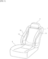
- FIG. 1 is a perspective view primarily illustrating an external shape of a vehicle seat used as the vehicle seat according to the present invention, with an illustration of an airbag device (airbag module) 20 omitted.
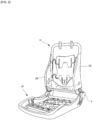
- FIG. 2 is a perspective view illustrating an internal structure (seat frame) functioning as a framework of the vehicle seat illustrated in FIG. 1 , with an illustration of the airbag device (airbag module) 20 omitted herein as well.
- FIG. 3 is a schematic side surface view of the vehicle seat according to the present invention, illustrating a condition where the airbag device (airbag module) 20 is stowed on a side surface (near side) near a left side seat door as observed from the outside in the vehicle width direction.
- the vehicle seat As illustrated in FIGS. 1 and 2 , seen as the location, the vehicle seat according to the present example is configured by: a seat cushion 2 of a part on which an occupant is seated; a seat back 1 forming a backrest; and a headrest 3 connected to the upper end of the seat back 1.
- a seat back frame 1f forming a skeleton of the seat is provided inside the seat back 1, a pad 16 (refer to FIG. 4 ) made of a urethane foam material or the like is provided on a surface and periphery thereof, and a surface of the pad 16 is covered with a skin 14 such as leather, fabric, or the like.
- a seating frame 2f is provided on a bottom side of the seat cushion 2. Similar to the seat back 1, a pad made of a urethane foam material or the like is provided on an upper surface and periphery thereof, and a surface of the pad is covered by the skin 14 ( FIG. 4 ) such as leather, fabric, or the like.
- the seating frame 2f and the seat back frame 1f are connected via a reclining mechanism 4.
- the seat back frame 1f is configured in a frame shape by: a side frame 10 arranged so as to be separated into the left and right and extending in a vertical direction; an upper frame connected to an upper end part of the side frame 10; and a lower frame connected to a lower end part thereof.
- a cushion member is provided outside a headrest frame to configure the headrest 3.
- FIG. 4 is a cross sectional view illustrating the structure of the vehicle seat according to the present invention, corresponding to a part of a cross section in an A1-A1 direction of FIG. 3 .
- the side frame 10 can be molded of resin or metal and, as illustrated in FIG. 4 , can be formed into an L-shaped cross sectional shape or a U-shaped cross sectional shape.
- An airbag module (side airbag device) 20 is secured to the inside (seat center side) and front side of the side frame 10.
- the seat back 1 includes a side supporting part 12 which swells in the vehicle traveling direction (vehicle front) on a vehicle width direction side part (end part).
- a urethane pad 16 is arranged inside the side supporting part 12, and the side airbag device 20 is stored in a gap of the urethane pad 16.
- the side airbag device 20 includes: an airbag 33 that restrains an occupant when expanded and deployed; and an inflator 30 that supplies an expansion gas to the airbag 33.
- a start region 26 is formed in the side supporting part 12 as a starting point when the side supporting part 12 bends towards the occupant side due to the expansion of a second chamber 36 (refer to FIG. 24 ).
- the start region 26 can be any one of a notch, recess, or thin region, or combinations thereof.
- the start region 26 may be formed at only a urethane 16 part inside the side supporting part 12. Furthermore, the start region 26 can be omitted.
- the compressed airbag 33 is secured to the side frame 10 via the brackets 52 and 54. Details of the brackets 52 and 54 are described below.
- the airbag 33 may be covered by a soft cover made of fabric (see FIG. 20 to FIG. 23 ).
- the airbag 33 can appropriately use an appropriate compressing method other than folding into a bellows shape, or rolling ("folding" includes rolling). Details are described below. Note that in FIG. 4 , reference code 25 indicates a door trim.
- FIG. 5 is a schematic side view of the vehicle seat according to the present invention, illustrating a condition where the airbag is deployed as observed from the outside in the vehicle width direction.
- the airbag 33 is provided with a main chamber 34 that deploys toward the front of the side support part 12 and a pre-push chamber 36 that deploys to the inside of the main chamber 34 in the width direction of the vehicle.
- FIG. 6 is a schematic diagram of the structure of the side airbag device according to the present invention, illustrating the deployed state of the airbag 33 corresponding to the cross section in the A2-A2 direction of FIG. 5 .
- the airbag 33 comprises the main chamber 34 that deploys toward the front of the side support part 12 of the seat, and the pre-push chamber 36 that houses the inflator 30 and begins to deploy prior to the main chamber 34 to the inside of the main chamber 34 in the vehicle width direction.
- An internal vent hole (not shown) is provided in the partitioning part (boundary portion) between the main chamber 34 and the pre-push chamber 36, through which expansion gas flows from the pre-push chamber 36 to the main chamber 34.
- An exhaust vent V (not shown) is formed on the front end part of the main chamber 34 for exhausting the gas to the outside. Note that at least one exhaust vent for exhausting the gas to the outside can be formed on a front end part of the pre-push chamber 36, similar to the main chamber 34.
- the main chamber 34 is partitioned into a forward chamber 34F and a rear chamber 34R by a partition panel 134c.
- An internal vent V34d is formed in the partition panel 134c for the expansion gas to flow from the rear chamber 34R to the forward chamber 34F.
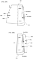
- FIG. 7 is a rear view (A) and a side view (B) of the structure of the brackets 52 and 54 employed in the airbag device according to the present invention.
- the rear view (A) illustrates a view observed from the rear of the vehicle
- the side view (B) illustrates a view observed from the outer side of the vehicle seat (opposite side of the occupant).
- the airbag 33 is omitted and only the inflator 30 is shown.
- the brackets (52, 54) are provided with a first plate 54 extending in a vertical direction and a second plate 52 through which two stud bolts 32a, 32b that are connected to the inflator 30 are inserted through, such that the second plate 52 is directly secured to the side frame 10.
- These types of brackets are generally arranged such that the first plate 54 and second plate 52 are orthogonal when viewed in a cross section perpendicular to the longitudinal direction (see FIG. 4 and FIG. 6 ), and the first plate 54 and the second plate 52 are connected to each other by welding or the like.
- the first plate 54 of the bracket has a first surface 54a that faces the vehicle traveling direction, and a main fold portion (main chamber 34) of the airbag 33 in a stowed state is arranged along the first surface 54a.
- the first surface 54a of the first plate 54 is a reaction force surface, and thus the airbag 33 reliably and quickly deploys in a forward direction.
- the second plate 52 of the bracket has a second surface 52a facing the occupant side, and mainly the pre-push chamber 36 of the airbag 33 is arranged on said second surface 52a.
- the pre-push chamber 36 When the pre-push chamber 36 is deployed, the second surface 52a of the second plate 52 becomes a reaction force surface, causing the pre-push chamber 36 to deploy reliably and quickly in the direction of the occupant (inner side).
- the reference sign "D0" indicates a direction in which a majority of the upper portion of the first plate 54 extends.
- the airbag 33 is arranged and stowed so that the reference line L0 (such as in FIG. 5 ) set on the airbag 33 coincides with this direction D0.
- the line H0 in FIG. 4 and FIG. 6 corresponds to the reference line L0 when observed from the vertical direction.
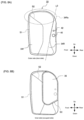
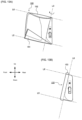
- FIGS. 8(A) and 8(B) are plan views (side views) illustrating the structure of the airbag 33 employed in the side airbag device of embodiment 1 of the present invention when viewed from the occupant side.
- the airbag 33 has a pre-push chamber 36 where the inflator 30 is stowed inside and deploys primarily on the occupant side (inner side) of the side frame 10, and a main chamber 34 that is connected to the pre-push chamber 36 and deploys primarily toward the front of the side frame 10.
- Each chamber 34 (34F, 34R) and 36 are compartmentally formed by stitches S1, S2, S3.
- the main chamber 34 is partitioned into a forward chamber 34F and a rear chamber 34R. Furthermore, the reference line L0 is set along the rear edge of the rear chamber 34R when viewed from the side in the vehicle width direction. Note, a non-expanding region is formed further behind the rear edge (L0) of the rear chamber 34R. The non-expanding region has an opening 40 into which the inflator 30 is inserted and an opening 42 through which the upper stud bolt 32a of the inflator 30 passes.
- the rear chamber 34R of the main chamber 34 is configured such that the shoulder protecting region 34Ra protecting the shoulder area of the occupant seated in the seat reaches near the front end part of the forward chamber 34F.
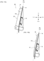
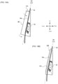
- FIGS. 9(A), 9(B), 10(A), and 10(B) are plan views (side views) illustrating the steps in folding the airbag 33 employed in the side airbag device according to embodiment 1 of the present invention.
- FIGS. 11(A) and (B) are plan views (side views) illustrating the steps in which the brackets (52, 54) are attached to the airbag 33 according to embodiment 1 of the present invention.
- the airbag 33 is folded or rolled from the front end side toward the rear end side along the direction of the first line L1, to form rolled part 53. Then, the lower end of the airbag 33 is further folded upwardly into a Z-shaped cross section using the second line L2 and the third line L3 as creases, which are substantially parallel to the first line L1, to form a Z-fold portion 55 ( FIG. 10(B) ).
- the brackets 52, 54 are attached with respect to the compressed airbag 33. Specifically, the stud bolts 32a, 32b of the inflator 30 are inserted into the second plate 52. Thereafter, the airbag is folded so that the reference line L0 on the airbag 33 side contacts the first surface 54a of the first plate 54 ( FIG. 11(B) ).
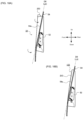
- FIGS. 12(A), 12(B), 12(C) , and FIGS. 13(A), 13(B) are plan views (side views) illustrating the steps in folding the airbag 133 employed in the side airbag device according to embodiment 2 of the present invention.
- FIGS. 14(A), 14(B) are plan views (side views) illustrating the steps in which the brackets 52, 54 are attached to the airbag 133 according to embodiment 2 of the present invention.
- the airbag 133 has a pre-push chamber (not shown) that stows the inflator 30 inside and deploys primarily on the occupant side (inner side) of the side frame 10, and a main chamber 134 that is connected to the pre-push chamber 36 and deploys primarily toward the front of the side frame 10.
- Each chamber 134 (134F, 314R) are compartmentally formed by stitches S1, S2.
- the configuration of the pre-push chamber is the same as that of the pre-push chamber 36 of embodiment 1 described above, and a duplicate description is omitted.
- the main chamber 134 is partitioned into a forward chamber 134F and a rear chamber 134R. Furthermore, the reference line L0 is set along the rear edge of the rear chamber 134R when viewed from the side in the vehicle width direction. A non-expanding region is formed further behind the rear edge L0 of the rear chamber 134R. The non-expanding region has an opening 40 into which the inflator 30 is inserted and an opening 42 through which the upper stud bolt 32a of the inflator 30 passes.
- the rear chamber 134R of the main chamber 134 is formed such that the waist protecting region 34Ra protecting the waist area of the occupant seated in the seat reaches near the front end of the forward chamber 134F.
- the lower end part 150 of the airbag 133 is folded upwardly into a Z-shaped cross section so that the fifth line L5, which is orthogonal to the reference line L0, becomes a fold of the lower edge, thereby forming a Z-fold 151 ( FIG. 13(A) ).
- the airbag may be simply folded back (upwards) towards the center of the main chamber so that the fifth line L5 becomes the fold of the lower edge.
- the sixth line L6 parallel to the fifth line L5 as a crease the upper end of the airbag 133 is folded (folded back) toward the center of the main chamber 134.
- the airbag 133 is then folded or rolled along the fifth line L5 (sixth line L6) (in a perpendicular direction) from the front end side to the rear end side to form a rolled part 153 ( FIG. 13(B) ).
- the brackets 52, 54 are attached with respect to the compressed airbag 133. Specifically, the stud bolts 32a, 32b of the inflator 30 are inserted into the second plate 52. Thereafter, the airbag is folded so that the reference line L0 on the airbag 133 side contacts the first surface 54a of the first plate 54 ( FIG. 14(B) ).
- FIGS. 15(A), 15(B) , and 16(A) , 16(B) , and 17(A), 17(B) are plan views (side views) illustrating the steps in folding the airbag 133 employed for the side airbag device according to embodiment 3 of the present invention.
- FIGS. 18(A), 18(B) are plan views (side views) illustrating the steps in which the brackets 52, 54 are attached to the airbag 133 according to embodiment 3 of the present invention.
- the airbag 133 used in embodiment 3 is structurally identical to the airbag 133 used in embodiment 2.
- the airbag 133 has a pre-push chamber (not shown) that stows the inflator 30 inside and deploys primarily on the occupant side (inner side) of the side frame 10, and a main chamber 134 that is connected to the pre-push chamber 36 and deploys primarily toward the front of the side frame 10.
- Each chamber 134 (134F, 314R) are compartmentally formed by stitches S1, S2.
- the main chamber 134 is partitioned into a forward chamber 134F and a rear chamber 134R. Furthermore, the reference line L0 is set along the rear edge of the rear chamber 134R when viewed from the side in the vehicle width direction. A non-expanding region is formed further behind the rear edge L0 of the rear chamber 134R. The non-expanding region has an opening 40 into which the inflator 30 is inserted and an opening 42 through which the upper stud bolt 32a of the inflator 30 passes.
- the rear chamber 134R of the main chamber 134 is formed such that the waist protecting region 34Ra protecting the waist area of the occupant seated in the seat reaches near the front end of the forward chamber 134F.
- the inflator 30 When folding the airbag 133, the inflator 30 is first inserted through the opening 40 and set inside the pre-push chamber as illustrated in FIG. 15(B) .
- a lower end part 250 is formed by tucking in or folding the lower end part of the waist protecting region 134Ra toward the center of the main chamber 134, using the fourth line L4 as a crease, which extends from near the front end of the waist protecting region 134Ra to near the rear end of the rear chamber 134R ( FIG. 16(A) ).
- the fourth line L4 of the main chamber 134 is substantially parallel to the line D2 extending in the front-rear direction of the stitch line S2 that serves as a partition between the forward chamber 134F and the rear chamber 134R.
- the upper end part of the airbag 133 is folded (folded back) toward the center of the main chamber 134 using the seventh line L7 extending in the front-back direction as a crease to form a folded part 252.
- the airbag 133 is folded or rolled from the front end side to the rear end side along the fourth line L4 to form a rolled part 253 ( FIG. 17(A) ).
- the region forward of the reference line L0 is folded toward the rear so that the eighth line L8 orthogonal to the seventh line L7 passing through the point P0 where the reference line L0 and the front edge of the rolled part 253 intersect becomes the foremost fold.
- a Z-fold part may be formed by folding the region forward of the reference line L0 in a Z-shaped cross section so that the eighth line L8 becomes the foremost fold.
- the brackets 52, 54 are attached relative to the compressed airbag 133. Specifically, the stud bolts 32a, 32b of the inflator 30 are inserted into the second plate 52. Thereafter, the airbag is folded so that the reference line L0 on the airbag 133 side touches the first surface 54a of the first plate 54 ( FIG. 18(B) ).
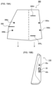
- cover member 300 that surrounds the airbag module configured as described above will be described below, taking the airbag 133 of embodiment 2 as an example. Note that the cover member 300 can also be applied to the airbag 33 in embodiment 1 and the airbag 133 in embodiment 3.
- FIG. 19 is a plan view (A) of a structure of a soft cover 300 that can be employed in the side airbag device of the present invention, and airbag (B) in a stowed state (compressed state).
- the soft cover 300 encloses the airbag module containing the airbags (34 and 36), the inflator 30, and the brackets 52, 54. Unlike the airbags 33, 133, the soft cover 300 is configured to not require a large amount of strength, in order to tear easily when the airbags (34, 36) deploy, and to not inhibit deployment of the airbags (34, 36).
- the soft cover 300 is provided with a pair of first through holes 302a, 302b that engage with the stud bolts 32a, 32b of the inflator 30, and a pair of second through holes 306a, 306b that encircle the folded airbag 133 and are then again engaged with said stud bolts 32a, 32b.
- a slit 308 is formed between the two second through holes 306a, 306b so that the distance between the second through holes 306a, 306b can be widened.
- the soft cover 300 has slits 304U, 304L into which the upper and lower portions of the first plate 54 are respectively inserted.
- FIGS. 20(A), 20(B) , and FIGS. 21(A), 21(B) are explanatory diagrams illustrating the steps of encircling the airbag module with the soft cover 300 according to the present invention.
- FIG. 22 is an explanatory diagram illustrating the state in which the airbag module is enclosed by the soft cover 300 according to the present invention.
- FIG. 23 is a cross-sectional view (A) in the B1-B1 direction of FIG. 22 , and a cross-sectional view (B) in the B2-B2 direction of FIG. 22 .
- the stud bolts 32a, 32b of the inflator 30 are first passed through (engaged with) the first through-holes 302a and 302b of the soft cover 300, as illustrated in FIG. 20(A) .
- the airbag module (133, 30) is encircled by the soft cover 300, and then the stud bolts 32a, 32b of the inflator 30 are passed through (engaged with) the second through holes 306a. 306b of the soft cover 300, as illustrated in FIG. 21(A) .
- the upper end and lower ends of the first plate 54 of the bracket are passed through the slits 304U, 304L. Then, the pre-push chamber side in which the inflator 30 is stowed is pulled toward the second plate 52 and the stud bolts 32a, 32b of the inflator 30 are inserted into the openings formed in the second plate 52 ( FIG. 22 ).
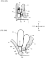
- FIG. 24 is a cross-sectional view illustrating the airbag according to the present invention in a deployed state, where (A) illustrates the state of deployment in the initial stages, and (B) illustrates deployment in later stages. Note that in FIG. 24 , illustration of the seat frame 10 is omitted for convenience of explanation.
- the pre-push chamber 36 deploys inside the side supporting part 12 in an initial activation stage of the airbag device 20, deforms such that a tip end side of the side supporting part 12 bends or protrudes on the vehicle side starting from the region 26 while the seat skin 14 tears from the sewn part 18, and restrains so as to push the occupant inward in the vehicle width direction.
- the surface 52a of the second plate 52 of the bracket acts as a reaction surface.
- Deployment of the pre-push chamber 36 causes the front side part of the side support part 12 to protrude toward the occupant side, thereby avoiding or minimizing the generation of forces that would push the occupant diagonally forward from the direction of the back of their body, thereby avoiding movement of the occupant in the direction that the seatbelt is pulled out. In other words, injury to the occupant can be suppressed, and restraining performance can be maximized.
- the main chamber 34 fully deploys toward the front of the vehicle to protect the occupants in the event of a collision.
- the surface 54a of the first plate of the bracket acts as a reaction force surface.
- the present invention has been described with reference to embodiments, the present invention is not limited in any way to these embodiments, and can be changed as appropriate within the scope of the technical idea of the present invention.
- a side airbag on the near side has been predominantly mentioned in the embodiments described above, use is also possible with a far side airbag (surface on the far side from a vehicle door of a vehicle seat), in very small vehicles such as a single seat vehicle (irrespective of the presence of a door, a vehicle including parts with only one seat in a single row), and the like.
Landscapes
- Engineering & Computer Science (AREA)
- Mechanical Engineering (AREA)
- Air Bags (AREA)
Claims (20)
- Fahrzeugsitz mit einer Seitenairbagvorrichtung (20), die in ihm verstaut und an einem Sitzseitenrahmen (10) befestigt ist, umfassend:einen Airbag (33,133), der einen Insassen zurückhält, wenn er sich ausdehnt und entfaltet;einen Gasgenerator (30), der dem Airbag (33,133) Expansionsgas zuführt;und eine Halterung (52,54), die den Airbag (33,133) und den Gasgenerator (30) zurückhält und mit dem Seitenrahmen (10) verbunden ist, wobeider Airbag (33,133) eine Vorschubkammer (36) mit dem darin verstauten Gasgenerator (30) und die sich hauptsächlich auf der Insassenseite (Innenseite) des Seitenrahmens (10) entfaltet, und eine Hauptkammer (34,134) einschließt, die mit der Vorschubkammer (36) verbunden ist und sich primär zu dem vorderen Teil des Seitenrahmens (10) hin entfaltet,die Halterung (52,54) eine erste Oberfläche (54a), die der Fahrtrichtung des Fahrzeugs (nach vorne) zugewandt ist, und eine zweite Oberfläche (52a) einschließt, die der Mittelseite des Sitzes (Innenseite) in der Breitenrichtung des Fahrzeugs zugewandt ist,und mindestens die Hauptkammer (34,134) oben auf der ersten Oberfläche (54a) der Halterung (52,54) angeordnet ist, wenn sich der Airbag (33,133) in einem gefalteten und/oder gerollten verstauten Zustand befindet, wobei in einem verstauten Zustand die Vorschubkammer (36) des Airbags (33,133) oben auf der zweiten Oberfläche (52a) der Halterung (52,54) angeordnet ist, wobei sich die Vorschubkammer (36) des Airbags (33,133) mit der zweiten Oberfläche (52a) der Halterung (52,54) als eine Reaktionsoberfläche zu der Insassenseite hin entfaltet, dadurch gekennzeichnet, dass die Hauptkammer (34,134) in eine Vorderkammer (34F,134F) und eine hintere Kammer (34R,134R) unterteilt ist;eine Referenzlinie (L0), von der Seite in der Fahrzeugbreitenrichtung betrachtet, entlang der hinteren Kante der hinteren Kammer (34R,134R) gesetzt wird; unddie hintere Kammer (34R,134R) derart konfiguriert ist, dass mindestens eine von einer schulterschützenden Region (34Ra,134Ra), die den Schulterbereich schützt, und einer taillenschützenden Region (34Ra,134Ra), die den Taillenbereich schützt, jeweils von einem in dem Sitz sitzenden Insassen, bis nahe dem vorderen Ende der Vorderkammer (34F,134F) reicht.
- Fahrzeugsitz nach Anspruch 1, wobei sich die Hauptkammer des Airbags (33,133) mit der ersten Oberfläche (54a) der Halterung (52,54) als eine Reaktionsoberfläche nach vorne entfaltet.
- Fahrzeugsitz nach Anspruch 1 oder 2, wobei die Halterung (52,54) eine plattenförmige erste Platte (54) mit einer ersten Oberfläche (54a) und eine plattenförmige zweite Platte (52) mit einer zweiten Oberfläche (52a) einschließt; und der Gasgenerator (30) an der zweiten Platte (52) befestigt ist.
- Fahrzeugsitz nach Anspruch 3, wobei die Halterung (52,54)
dadurch gekennzeichnet ist, dass die erste Platte (54) und die zweite Platte (52), in einem Querschnitt senkrecht zu der Längsrichtung betrachtet, nahezu orthogonal sind. - Fahrzeugsitz nach Anspruch 3 oder 4, wobei die hintere Kammer (34R,134R) derart konfiguriert ist, dass die schulterschützende Region (34Ra,134Ra), die den Schulterbereich des in dem Sitz sitzenden Insassen schützt, bis nahe dem vorderen Endabschnitt der Vorderkammer (34F,134F) reicht;die schulterschützende Region (34Ra,134Ra) des Airbags (33,133) unter Verwendung einer ersten Linie (L1) als eine Falte, die orthogonal zu der Referenzlinie (L0) ist und sich von nahe dem vorderen Endabschnitt der schulterschützenden Region (34Ra,134Ra) bis nahe dem hinteren Ende der hinteren Kammer (34R,134R) erstreckt, zu der Mitte der Hauptkammer (34,134) hin eingesteckt oder gefaltet wird;der Airbag (33,133) von der vorderen Endseite zu der hinteren Endseite in der Richtung der ersten Linie (L1) gefaltet oder gerollt wird;und die Referenzlinie (L0) entlang der ersten Oberfläche (54a) der ersten Platte (54) angeordnet ist, wenn der Airbag (33,133) an der Halterung (52,54) zurückgehalten wird.
- Fahrzeugsitz nach Anspruch 5, wobei der gefaltete oder gerollte untere Endabschnitt des Airbags (33,133) weiter nach oben in einen Z-förmigen Querschnitt mit einer zweiten Linie (L2) und einer dritten Linie (L3) gefaltet wird, die als Falten parallel zu der ersten Linie (L1) sind.
- Fahrzeugsitz nach Anspruch 3 oder 4, wobei die hintere Kammer (34R,134R) derart konfiguriert ist, dass die taillenschützende Region (34Ra,134Ra), die den Taillenbereich des in dem Sitz sitzenden Insassen schützt, bis nahe dem vorderen Endabschnitt der Vorderkammer (34F,134F) reicht;der untere Endabschnitt der taillenschützenden Region (34Ra,134Ra) des Airbags (33,133) unter Verwendung einer vierten Linie (L4) als eine Falte, die sich von nahe dem vorderen Endabschnitt der taillenschützenden Region (34Ra,134Ra) bis nahe des hinteren Endes der hinteren Kammer (34R,134R) ersteckt, zu der Mitte der Hauptkammer (34, 134) hin eingesteckt oder gefaltet wird;der eingesteckte oder gefaltete untere Endabschnitt des Airbags (33,133) nach oben in einen Z-förmigen Querschnitt gefaltet wird, sodass eine fünfte Linie (L5), die orthogonal zu der Referenzlinie (L0) ist, die Falte der Unterkante wird;der Airbag (33,133) entlang der fünften Linie (L5) von der vorderen Endseite zu der hinteren Endseite gefaltet oder gerollt wird; undund die Referenzlinie (L0) entlang der ersten Oberfläche (54a) der ersten Platte (54) angeordnet ist, wenn der Airbag (33,133) an der Halterung (52,54) zurückgehalten wird.
- Fahrzeugsitz nach Anspruch 7, wobei der Airbag (33,133) unter Verwendung einer sechsten Linie (L6), die parallel zu der fünften Linie (L5) ist, als eine Falte zu der Mitte der Hauptkammer (34,134) hin gefaltet wird, bevor er gefaltet oder gerollt wird.
- Fahrzeugsitz nach Anspruch 3 oder 4, wobei die hintere Kammer (34R,134R) derart konfiguriert ist, dass die taillenschützende Region (34Ra,134Ra), die den Taillenbereich des in dem Sitz sitzenden Insassen schützt, bis nahe dem vorderen Endabschnitt der Vorderkammer (34F,134F) reicht;der untere Endabschnitt der taillenschützenden Region (34Ra,134Ra) des Airbags (33,133) unter Verwendung einer vierten Linie (L4) als eine Falte, die sich von nahe dem vorderen Endabschnitt der taillenschützenden Region (34Ra,134Ra) bis nahe dem hinteren Ende der hinteren Kammer (34R,134R) erstreckt, zu der Mitte der Hauptkammer (34,134) hin eingesteckt oder gefaltet wird;der Airbag (33,133) entlang der vierten Linie (L4) von der vorderen Endseite zu der hinteren Endseite gefaltet oder gerollt wird;und die Referenzlinie (L0) entlang der ersten Oberfläche (54a) der ersten Platte (54) angeordnet ist, wenn der Airbag (33,133) an der Halterung (52,54) zurückgehalten wird.
- Fahrzeugsitz nach Anspruch 9, wobei der obere Endabschnitt des Airbags (33,133) unter Verwendung einer siebten Linie (L7), die sich in der Vorne-Hinten-Richtung erstreckt, als eine Falte zu der Mitte der Hauptkammer (34,134) hin gefaltet wird, bevor er gefaltet oder gerollt wird.
- Fahrzeugsitz nach Anspruch 10, wobei, wenn ein Punkt P0 der Punkt ist, wo sich die Referenzlinie (L0) und die vordere Kante der gefalteten oder gerollten Region schneiden, eine Region vor der Referenzlinie (L0) unter Verwendung einer achten Linie (L8), die orthogonal zu der siebten Linie (L7) ist, als eine Falte nach hinten gefaltet wird.
- Herstellungsverfahren eines Fahrzeugsitzes nach einem der Ansprüche 1 bis 11, umfassend:einen Schritt eines Anfertigens eines Airbags (33,133), der eine Vorschubkammer (36) mit dem darin verstauten Gasgenerator (30), der sich primär auf der Insassenseite (Innenseite) des Seitenrahmens (10) entfaltet, und eine Hauptkammer (34,134) einschließt, die mit der Vorschubkammer (36) verbunden ist und sich primär zu dem vorderen Teil des Seitenrahmens (10) hin entfaltet;einen Schritt des Anfertigens einer Halterung (52,54), die, wenn sie mit dem Seitenrahmen (10) verbunden ist, eine erste Oberfläche (54a), die zu der Fahrtrichtung des Fahrzeugs (nach vorne) hin gewandt ist, und eine zweite Oberfläche (52a) aufweist, die der Mitte des Sitzes in der Breitenrichtung des Fahrzeugs zugewandt ist;einen Schritt eines Faltens und/oder Rollens des Airbags (33,133) in einen verstauten Zustand; undeinen Schritt eines derartigen Zurückhaltens des Airbags (33,133) in Bezug auf die Halterung (52,54), dass mindestens die Hauptkammer (34,134) des Airbags (33,133) in einem verstauten Zustand an der ersten Oberfläche (54a) der Halterung (52,54) positioniert ist.
- Herstellungsverfahren eines Fahrzeugsitzes nach Anspruch 12, wobei die Halterung (52,54) eine plattenförmige erste Platte (54) mit einer ersten Oberfläche (54a) und eine plattenförmige zweite Platte (52) mit einer zweiten Oberfläche (52a) einschließt; und der Gasgenerator (30) an der zweiten Platte (52) befestigt ist.
- Herstellungsverfahren eines Fahrzeugsitzes nach Anspruch 13, wobei die schulterschützende Region (34Ra,134Ra) der hinteren Kammer (34R,134R), die den Schulterbereich des in dem Sitz sitzenden Insassen schützt, bis nahe dem vorderen Endabschnitt der Vorderkammer (34F,134F) reicht; ferner umfassend:einen Schritt, wo die schulterschützende Region (34Ra,134Ra) des Airbags (33,133) unter Verwendung einer ersten Linie (L1) als eine Falte, die orthogonal zu der Referenzlinie (L0) ist und sich von nahe dem vorderen Endabschnitt der schulterschützenden Region (34Ra,134Ra) bis nahe dem hinteren Ende der hinteren Kammer (34R,134R) erstreckt, zu der Mitte der Hauptkammer (34,134) hin eingesteckt oder gefaltet wird;einen Schritt, wo der Airbag (33,133) von der vorderen Kante zu der hinteren Kante hin in einer Richtung, die nahezu orthogonal zu der ersten Linie (L1) ist, als eine Längsrichtung gefaltet oder gerollt wird; undeinen Schritt, wo der Airbag (33,133) in der Halterung (52,54) derart zurückgehalten wird, dass die Referenzlinie (L0) entlang der ersten Oberfläche (54a) der ersten Platte (54) positioniert ist.
- Herstellungsverfahren eines Fahrzeugsitzes nach Anspruch 14, ferner umfassend einen Schritt, wo der gefaltete oder gerollte untere Endabschnitt des Airbags (33,133) weiter nach oben in einen Z-förmigen Querschnitt mit einer zweiten Linie (L2) und einer dritten Linie (L3), die parallel zu der ersten Linie (L1) sind, als Falten gefaltet wird.
- Herstellungsverfahren eines Fahrzeugsitz nach Anspruch 13, wobei die taillenschützende Region (34Ra,134Ra) der hinteren Kammer (34R,134R), die den Taillenbereich des in dem Sitz sitzenden Insassen schützt, bis nahe dem vorderen Endabschnitt der Vorderkammer (34F,134F) reicht; ferner umfassend:einen Schritt, wo der untere Endabschnitt der taillen- und der schulterschützenden (34Ra,134Ra) Region des Airbags (33,133) unter Verwendung einer vierten Linie (L4) als eine Falte, die sich von nahe dem vorderen Endabschnitt der taillenschützenden Region (34Ra,134Ra) bis nahe dem hinteren Ende der hinteren Kammer (34R,134R) erstreckt, zu der Mitte der Hauptkammer (34,134) hin eingesteckt oder gefaltet wird;einen Schritt, wo der eingesteckte oder gefaltete untere Endabschnitt des Airbags (33,133) nach oben in einen Z-förmigen Querschnitt gefaltet wird, sodass eine fünfte Linie (L5), die nahezu orthogonal zu der Referenzlinie (L0) ist, die Falte der Unterkante wird;einen Schritt, wo der Airbag (33,133) von der vorderen Kante zu der hinteren Kante hin in eine Richtung, die orthogonal zu der fünften Linie (L5) ist, als eine Längsrichtung gefaltet oder gerollt wird; undeinen Schritt, wo der Airbag (33,133) in der Halterung (52,54) derart zurückgehalten wird, dass die Referenzlinie (L0) entlang der ersten Oberfläche (54a) der ersten Platte (54) positioniert ist.
- Herstellungsverfahren eines Fahrzeugsitzes nach Anspruch 16, wobei der Airbag (33,133) unter Verwendung einer sechsten Linie (L6), die parallel zu der fünften Linie (L5) ist, als eine Falte mit dem oberen Endabschnitt zu der Mitte der Hauptkammer (34,134) hin gefaltet wird, bevor er gefaltet oder gerollt wird.
- Herstellungsverfahren eines Fahrzeugsitzes nach Anspruch 13, wobei die Referenzlinie (L0) angeordnet ist, um im Wesentlichen parallel zu der Längsrichtung der ersten Oberfläche (54a) der ersten Platte (54) zu sein, wenn der Airbag (33,133) in der Halterung (52,54) zurückgehalten wird,wobei die taillenschützende Region (34Ra,134Ra) der hinteren Kammer (34R,134R), die den Taillenbereich des in dem Sitz sitzenden Insassen schützt, bis nahe dem vorderen Endabschnitt der Vorderkammer (34F,134F) reicht.einen Schritt, wo der untere Endabschnitt der taillenschützenden Region (34Ra,134Ra) des Airbags (33,133) unter Verwendung einer vierten Linie (L4) als eine Falte, die sich von nahe dem vorderen Endabschnitt der taillenschützenden Region (34Ra,134Ra) bis nahe dem hinteren Ende der hinteren Kammer (34R,134R) erstreckt, zu der Mitte der Hauptkammer (34, 134) hin eingesteckt oder gefaltet wird;einen Schritt, wo der Airbag (33,133) entlang der vierten Linie (L4) von der vorderen Endseite zu der hinteren Endseite gefaltet oder gerollt wird; undeinen Schritt, wo der Airbag (33,133) in der Halterung (52,54) derart zurückgehalten wird, dass die Referenzlinie (L0) entlang der ersten Oberfläche (54a) der ersten Platte (54) positioniert ist.
- Herstellungsverfahren eines Fahrzeugsitzes nach Anspruch 18, ferner umfassend einen Schritt, wo der obere Endabschnitt des Airbags (33,133) unter Verwendung einer siebten Linie (L7), die sich in der Vorne-Hinten-Richtung erstreckt, als eine Falte zu der Mitte der Hauptkammer (34,134) hin gefaltet wird, bevor er gefaltet oder gerollt wird.
- Herstellungsverfahren eines Fahrzeugsitzes nach Anspruch 19, wobei, wenn ein Punkt P0 der Punkt ist, wo sich die Referenzlinie (L0) und die vordere Kante der gefalteten oder gerollten Region schneiden, eine Region vor der Referenzlinie (L0) unter Verwendung einer achten Linie (L8), die den Punkt (P0) durchläuft und orthogonal zu der siebten Linie (L7) ist, als eine vorderste Falte nach hinten gefaltet wird.
Applications Claiming Priority (2)
| Application Number | Priority Date | Filing Date | Title |
|---|---|---|---|
| JP2018240381 | 2018-12-21 | ||
| PCT/JP2019/041061 WO2020129386A1 (ja) | 2018-12-21 | 2019-10-18 | サイドエアバッグ装置、これを備えた車両用シート、及びサイドエアバッグ装置の製造方法 |
Publications (3)
| Publication Number | Publication Date |
|---|---|
| EP3900985A1 EP3900985A1 (de) | 2021-10-27 |
| EP3900985A4 EP3900985A4 (de) | 2022-08-17 |
| EP3900985B1 true EP3900985B1 (de) | 2025-05-07 |
Family
ID=71100819
Family Applications (1)
| Application Number | Title | Priority Date | Filing Date |
|---|---|---|---|
| EP19899024.4A Active EP3900985B1 (de) | 2018-12-21 | 2019-10-18 | Seitenairbagvorrichtung, damit ausgestatteter fahrzeugsitz und verfahren zur herstellung einer seitenairbagvorrichtung |
Country Status (6)
| Country | Link |
|---|---|
| US (1) | US11833990B2 (de) |
| EP (1) | EP3900985B1 (de) |
| JP (1) | JP7073534B2 (de) |
| KR (1) | KR102656870B1 (de) |
| CN (1) | CN113423617B (de) |
| WO (1) | WO2020129386A1 (de) |
Families Citing this family (11)
| Publication number | Priority date | Publication date | Assignee | Title |
|---|---|---|---|---|
| JP7008816B2 (ja) * | 2018-06-19 | 2022-01-25 | オートリブ ディベロップメント エービー | サイドエアバッグ装置及び、これを備えた車両用シート |
| EP3978322A4 (de) * | 2019-05-31 | 2023-07-05 | Autoliv Development AB | Seitenairbagvorrichtung und verfahren zur herstellung einer seitenairbagvorrichtung |
| WO2021206051A1 (ja) * | 2020-04-09 | 2021-10-14 | オートリブ ディベロップメント エービー | サイドエアバッグ装置 |
| JP7381771B2 (ja) * | 2020-10-13 | 2023-11-16 | オートリブ ディベロップメント エービー | サイドエアバッグ装置 |
| JP7564735B2 (ja) * | 2021-03-02 | 2024-10-09 | 本田技研工業株式会社 | サイドエアバッグ装置 |
| JP7564734B2 (ja) * | 2021-03-02 | 2024-10-09 | 本田技研工業株式会社 | サイドエアバッグ装置 |
| JP7554345B2 (ja) * | 2021-03-31 | 2024-09-19 | オートリブ ディベロップメント エービー | サイドエアバッグ装置、及びその製造方法 |
| KR102626944B1 (ko) * | 2021-08-11 | 2024-01-19 | 아우토리브 디벨롭먼트 아베 | 자동차의 파 사이드 에어백 장치 및 그의 폴딩 방법 |
| JP7591485B2 (ja) * | 2021-10-23 | 2024-11-28 | オートリブ ディベロップメント エービー | エアバッグ装置及び製造方法 |
| JP7672571B2 (ja) * | 2022-02-16 | 2025-05-07 | オートリブ ディベロップメント エービー | サイドエアバッグ装置、及びその製造方法 |
| JP7544094B2 (ja) * | 2022-04-26 | 2024-09-03 | トヨタ自動車株式会社 | シート搭載型エアバッグ装置 |
Citations (1)
| Publication number | Priority date | Publication date | Assignee | Title |
|---|---|---|---|---|
| EP3357764A1 (de) * | 2017-02-03 | 2018-08-08 | Toyota Jidosha Kabushiki Kaisha | Fahrzeugsitz mit seitenairbagvorrichtung |
Family Cites Families (25)
| Publication number | Priority date | Publication date | Assignee | Title |
|---|---|---|---|---|
| GB2397048A (en) * | 2003-01-10 | 2004-07-14 | Autoliv Dev | Vehicle seat comprising airbag |
| GB2397047B (en) * | 2003-01-10 | 2006-02-22 | Autoliv Development Ab | Improvements in or relating to vehicle air-seats and air-bag units |
| EP1810891B1 (de) * | 2006-01-20 | 2012-10-31 | Delphi Technologies, Inc. | Luftsackmodul für Kraftfahrzeuge |
| JP4760533B2 (ja) * | 2006-05-26 | 2011-08-31 | 豊田合成株式会社 | エアバッグ装置 |
| JP4816387B2 (ja) * | 2006-10-02 | 2011-11-16 | 豊田合成株式会社 | サイドエアバッグ装置 |
| JP2008201172A (ja) * | 2007-02-16 | 2008-09-04 | Toyota Motor Corp | サイドエアバッグ装置。 |
| JP4962185B2 (ja) * | 2007-07-19 | 2012-06-27 | 豊田合成株式会社 | サイドエアバッグ装置 |
| JP4952422B2 (ja) | 2007-07-19 | 2012-06-13 | 豊田合成株式会社 | サイドエアバッグ装置 |
| JP4986910B2 (ja) * | 2008-03-31 | 2012-07-25 | オートリブ ディベロップメント エービー | エアバッグ装置 |
| JP5534708B2 (ja) * | 2009-04-22 | 2014-07-02 | マツダ株式会社 | サイドエアバッグ装置およびそのバッグ部の折畳み方法 |
| DE102011086471A1 (de) | 2011-11-16 | 2013-05-16 | Lear Corporation | Fahrzeugsitzanordnung mit Airbag an innenliegender Seite |
| KR101355594B1 (ko) * | 2011-12-07 | 2014-01-29 | 현대자동차주식회사 | 차량용 듀얼 챔버 사이드에어백 장치 |
| JP5692178B2 (ja) * | 2012-07-23 | 2015-04-01 | トヨタ自動車株式会社 | 車両用サイドエアバッグ装置 |
| WO2014017211A1 (ja) * | 2012-07-25 | 2014-01-30 | トヨタ自動車株式会社 | サイドエアバッグの展開方向規制構造 |
| JP5942772B2 (ja) * | 2012-10-18 | 2016-06-29 | トヨタ自動車株式会社 | サイドエアバッグ装置を搭載した車両用シート |
| JP6067489B2 (ja) * | 2013-06-10 | 2017-01-25 | 豊田合成株式会社 | サイドエアバッグ装置 |
| JP6179469B2 (ja) * | 2014-06-23 | 2017-08-16 | トヨタ自動車株式会社 | ファーサイドエアバッグ装置 |
| KR102004535B1 (ko) * | 2015-07-11 | 2019-10-01 | 오토리브 디벨로프먼트 에이비 | 승차인 보호 장치 |
| KR102095578B1 (ko) * | 2016-06-01 | 2020-03-31 | 오토리브 디벨로프먼트 에이비 | 승차인 보호 장치 |
| JP6561942B2 (ja) * | 2016-08-22 | 2019-08-21 | トヨタ自動車株式会社 | サイドエアバッグ装置を搭載した車両用シート |
| WO2018105324A1 (ja) * | 2016-12-05 | 2018-06-14 | オートリブ ディベロップメント エービー | サイドエアバッグ装置 |
| JP6748294B2 (ja) * | 2017-03-30 | 2020-08-26 | オートリブ ディベロップメント エービー | 乗員保護装置 |
| JP6856482B2 (ja) | 2017-09-20 | 2021-04-07 | トヨタ自動車株式会社 | サイドエアバッグ装置を搭載した車両用シート及びサイドエアバッグ装置 |
| US11214223B2 (en) * | 2017-11-02 | 2022-01-04 | Autoliv Development Ab | Side airbag device |
| JP7180456B2 (ja) * | 2019-03-06 | 2022-11-30 | トヨタ自動車株式会社 | ファーサイドエアバッグ装置を備えたシート構造 |
-
2019
- 2019-10-18 JP JP2020561181A patent/JP7073534B2/ja active Active
- 2019-10-18 CN CN201980077228.1A patent/CN113423617B/zh active Active
- 2019-10-18 WO PCT/JP2019/041061 patent/WO2020129386A1/ja not_active Ceased
- 2019-10-18 US US17/309,762 patent/US11833990B2/en active Active
- 2019-10-18 KR KR1020217018878A patent/KR102656870B1/ko active Active
- 2019-10-18 EP EP19899024.4A patent/EP3900985B1/de active Active
Patent Citations (1)
| Publication number | Priority date | Publication date | Assignee | Title |
|---|---|---|---|---|
| EP3357764A1 (de) * | 2017-02-03 | 2018-08-08 | Toyota Jidosha Kabushiki Kaisha | Fahrzeugsitz mit seitenairbagvorrichtung |
Also Published As
| Publication number | Publication date |
|---|---|
| CN113423617B (zh) | 2023-05-02 |
| EP3900985A4 (de) | 2022-08-17 |
| JPWO2020129386A1 (ja) | 2021-09-27 |
| JP7073534B2 (ja) | 2022-05-23 |
| KR20210089775A (ko) | 2021-07-16 |
| EP3900985A1 (de) | 2021-10-27 |
| US20220055570A1 (en) | 2022-02-24 |
| US11833990B2 (en) | 2023-12-05 |
| KR102656870B1 (ko) | 2024-04-16 |
| WO2020129386A1 (ja) | 2020-06-25 |
| CN113423617A (zh) | 2021-09-21 |
Similar Documents
| Publication | Publication Date | Title |
|---|---|---|
| EP3900985B1 (de) | Seitenairbagvorrichtung, damit ausgestatteter fahrzeugsitz und verfahren zur herstellung einer seitenairbagvorrichtung | |
| EP3663140B1 (de) | Insassenschutzvorrichtung | |
| US11752965B2 (en) | Side airbag device and method for manufacturing side airbag device | |
| EP3604047B1 (de) | Passagierschutzvorrichtung | |
| EP3778311B1 (de) | Seitenairbagvorrichtung und fahrzeugsitz | |
| US11351947B2 (en) | Passenger protection apparatus | |
| US11267433B2 (en) | Side airbag device and vehicle seat provided with same | |
| JP2018012476A (ja) | 車両用乗員拘束装置 | |
| US11358555B2 (en) | Vehicle seat | |
| US20200346604A1 (en) | Side airbag apparatus and vehicle seat including the same | |
| JP7554345B2 (ja) | サイドエアバッグ装置、及びその製造方法 | |
| KR20250116659A (ko) | 승차인 구속 장치 |
Legal Events
| Date | Code | Title | Description |
|---|---|---|---|
| STAA | Information on the status of an ep patent application or granted ep patent |
Free format text: STATUS: THE INTERNATIONAL PUBLICATION HAS BEEN MADE |
|
| PUAI | Public reference made under article 153(3) epc to a published international application that has entered the european phase |
Free format text: ORIGINAL CODE: 0009012 |
|
| STAA | Information on the status of an ep patent application or granted ep patent |
Free format text: STATUS: REQUEST FOR EXAMINATION WAS MADE |
|
| 17P | Request for examination filed |
Effective date: 20210607 |
|
| AK | Designated contracting states |
Kind code of ref document: A1 Designated state(s): AL AT BE BG CH CY CZ DE DK EE ES FI FR GB GR HR HU IE IS IT LI LT LU LV MC MK MT NL NO PL PT RO RS SE SI SK SM TR |
|
| DAV | Request for validation of the european patent (deleted) | ||
| DAX | Request for extension of the european patent (deleted) | ||
| A4 | Supplementary search report drawn up and despatched |
Effective date: 20220720 |
|
| RIC1 | Information provided on ipc code assigned before grant |
Ipc: B60R 21/237 20060101ALI20220714BHEP Ipc: B60R 21/233 20060101ALI20220714BHEP Ipc: B60R 21/207 20060101AFI20220714BHEP |
|
| STAA | Information on the status of an ep patent application or granted ep patent |
Free format text: STATUS: EXAMINATION IS IN PROGRESS |
|
| 17Q | First examination report despatched |
Effective date: 20240319 |
|
| GRAP | Despatch of communication of intention to grant a patent |
Free format text: ORIGINAL CODE: EPIDOSNIGR1 |
|
| STAA | Information on the status of an ep patent application or granted ep patent |
Free format text: STATUS: GRANT OF PATENT IS INTENDED |
|
| INTG | Intention to grant announced |
Effective date: 20241217 |
|
| GRAS | Grant fee paid |
Free format text: ORIGINAL CODE: EPIDOSNIGR3 |
|
| GRAA | (expected) grant |
Free format text: ORIGINAL CODE: 0009210 |
|
| STAA | Information on the status of an ep patent application or granted ep patent |
Free format text: STATUS: THE PATENT HAS BEEN GRANTED |
|
| AK | Designated contracting states |
Kind code of ref document: B1 Designated state(s): AL AT BE BG CH CY CZ DE DK EE ES FI FR GB GR HR HU IE IS IT LI LT LU LV MC MK MT NL NO PL PT RO RS SE SI SK SM TR |
|
| REG | Reference to a national code |
Ref country code: GB Ref legal event code: FG4D |
|
| REG | Reference to a national code |
Ref country code: CH Ref legal event code: EP |
|
| REG | Reference to a national code |
Ref country code: DE Ref legal event code: R096 Ref document number: 602019069798 Country of ref document: DE |
|
| REG | Reference to a national code |
Ref country code: IE Ref legal event code: FG4D |
|
| REG | Reference to a national code |
Ref country code: NL Ref legal event code: MP Effective date: 20250507 |
|
| PG25 | Lapsed in a contracting state [announced via postgrant information from national office to epo] |
Ref country code: PT Free format text: LAPSE BECAUSE OF FAILURE TO SUBMIT A TRANSLATION OF THE DESCRIPTION OR TO PAY THE FEE WITHIN THE PRESCRIBED TIME-LIMIT Effective date: 20250908 Ref country code: FI Free format text: LAPSE BECAUSE OF FAILURE TO SUBMIT A TRANSLATION OF THE DESCRIPTION OR TO PAY THE FEE WITHIN THE PRESCRIBED TIME-LIMIT Effective date: 20250507 Ref country code: ES Free format text: LAPSE BECAUSE OF FAILURE TO SUBMIT A TRANSLATION OF THE DESCRIPTION OR TO PAY THE FEE WITHIN THE PRESCRIBED TIME-LIMIT Effective date: 20250507 |
|
| REG | Reference to a national code |
Ref country code: LT Ref legal event code: MG9D |
|
| PG25 | Lapsed in a contracting state [announced via postgrant information from national office to epo] |
Ref country code: NO Free format text: LAPSE BECAUSE OF FAILURE TO SUBMIT A TRANSLATION OF THE DESCRIPTION OR TO PAY THE FEE WITHIN THE PRESCRIBED TIME-LIMIT Effective date: 20250807 Ref country code: GR Free format text: LAPSE BECAUSE OF FAILURE TO SUBMIT A TRANSLATION OF THE DESCRIPTION OR TO PAY THE FEE WITHIN THE PRESCRIBED TIME-LIMIT Effective date: 20250808 |
|
| PG25 | Lapsed in a contracting state [announced via postgrant information from national office to epo] |
Ref country code: NL Free format text: LAPSE BECAUSE OF FAILURE TO SUBMIT A TRANSLATION OF THE DESCRIPTION OR TO PAY THE FEE WITHIN THE PRESCRIBED TIME-LIMIT Effective date: 20250507 Ref country code: PL Free format text: LAPSE BECAUSE OF FAILURE TO SUBMIT A TRANSLATION OF THE DESCRIPTION OR TO PAY THE FEE WITHIN THE PRESCRIBED TIME-LIMIT Effective date: 20250507 |
|
| REG | Reference to a national code |
Ref country code: AT Ref legal event code: MK05 Ref document number: 1792155 Country of ref document: AT Kind code of ref document: T Effective date: 20250507 |
|
| PG25 | Lapsed in a contracting state [announced via postgrant information from national office to epo] |
Ref country code: BG Free format text: LAPSE BECAUSE OF FAILURE TO SUBMIT A TRANSLATION OF THE DESCRIPTION OR TO PAY THE FEE WITHIN THE PRESCRIBED TIME-LIMIT Effective date: 20250507 |
|
| PG25 | Lapsed in a contracting state [announced via postgrant information from national office to epo] |
Ref country code: HR Free format text: LAPSE BECAUSE OF FAILURE TO SUBMIT A TRANSLATION OF THE DESCRIPTION OR TO PAY THE FEE WITHIN THE PRESCRIBED TIME-LIMIT Effective date: 20250507 |
|
| PG25 | Lapsed in a contracting state [announced via postgrant information from national office to epo] |
Ref country code: AT Free format text: LAPSE BECAUSE OF FAILURE TO SUBMIT A TRANSLATION OF THE DESCRIPTION OR TO PAY THE FEE WITHIN THE PRESCRIBED TIME-LIMIT Effective date: 20250507 |
|
| PG25 | Lapsed in a contracting state [announced via postgrant information from national office to epo] |
Ref country code: RS Free format text: LAPSE BECAUSE OF FAILURE TO SUBMIT A TRANSLATION OF THE DESCRIPTION OR TO PAY THE FEE WITHIN THE PRESCRIBED TIME-LIMIT Effective date: 20250807 |
|
| PG25 | Lapsed in a contracting state [announced via postgrant information from national office to epo] |
Ref country code: IS Free format text: LAPSE BECAUSE OF FAILURE TO SUBMIT A TRANSLATION OF THE DESCRIPTION OR TO PAY THE FEE WITHIN THE PRESCRIBED TIME-LIMIT Effective date: 20250907 |
|
| PG25 | Lapsed in a contracting state [announced via postgrant information from national office to epo] |
Ref country code: LV Free format text: LAPSE BECAUSE OF FAILURE TO SUBMIT A TRANSLATION OF THE DESCRIPTION OR TO PAY THE FEE WITHIN THE PRESCRIBED TIME-LIMIT Effective date: 20250507 |
|
| PGFP | Annual fee paid to national office [announced via postgrant information from national office to epo] |
Ref country code: DE Payment date: 20251028 Year of fee payment: 7 |
|
| PGFP | Annual fee paid to national office [announced via postgrant information from national office to epo] |
Ref country code: GB Payment date: 20251023 Year of fee payment: 7 |
|
| PG25 | Lapsed in a contracting state [announced via postgrant information from national office to epo] |
Ref country code: DK Free format text: LAPSE BECAUSE OF FAILURE TO SUBMIT A TRANSLATION OF THE DESCRIPTION OR TO PAY THE FEE WITHIN THE PRESCRIBED TIME-LIMIT Effective date: 20250507 Ref country code: SM Free format text: LAPSE BECAUSE OF FAILURE TO SUBMIT A TRANSLATION OF THE DESCRIPTION OR TO PAY THE FEE WITHIN THE PRESCRIBED TIME-LIMIT Effective date: 20250507 |
|
| PGFP | Annual fee paid to national office [announced via postgrant information from national office to epo] |
Ref country code: FR Payment date: 20251027 Year of fee payment: 7 |
|
| PG25 | Lapsed in a contracting state [announced via postgrant information from national office to epo] |
Ref country code: CZ Free format text: LAPSE BECAUSE OF FAILURE TO SUBMIT A TRANSLATION OF THE DESCRIPTION OR TO PAY THE FEE WITHIN THE PRESCRIBED TIME-LIMIT Effective date: 20250507 |
|
| PG25 | Lapsed in a contracting state [announced via postgrant information from national office to epo] |
Ref country code: EE Free format text: LAPSE BECAUSE OF FAILURE TO SUBMIT A TRANSLATION OF THE DESCRIPTION OR TO PAY THE FEE WITHIN THE PRESCRIBED TIME-LIMIT Effective date: 20250507 |
|
| PG25 | Lapsed in a contracting state [announced via postgrant information from national office to epo] |
Ref country code: SK Free format text: LAPSE BECAUSE OF FAILURE TO SUBMIT A TRANSLATION OF THE DESCRIPTION OR TO PAY THE FEE WITHIN THE PRESCRIBED TIME-LIMIT Effective date: 20250507 Ref country code: RO Free format text: LAPSE BECAUSE OF FAILURE TO SUBMIT A TRANSLATION OF THE DESCRIPTION OR TO PAY THE FEE WITHIN THE PRESCRIBED TIME-LIMIT Effective date: 20250507 |
|
| PG25 | Lapsed in a contracting state [announced via postgrant information from national office to epo] |
Ref country code: IT Free format text: LAPSE BECAUSE OF FAILURE TO SUBMIT A TRANSLATION OF THE DESCRIPTION OR TO PAY THE FEE WITHIN THE PRESCRIBED TIME-LIMIT Effective date: 20250507 |