EP2481642A1 - Seitenairbag - Google Patents
Seitenairbag Download PDFInfo
- Publication number
- EP2481642A1 EP2481642A1 EP11732896A EP11732896A EP2481642A1 EP 2481642 A1 EP2481642 A1 EP 2481642A1 EP 11732896 A EP11732896 A EP 11732896A EP 11732896 A EP11732896 A EP 11732896A EP 2481642 A1 EP2481642 A1 EP 2481642A1
- Authority
- EP
- European Patent Office
- Prior art keywords
- side airbag
- arm
- occupant
- base fabric
- deployed
- Prior art date
- Legal status (The legal status is an assumption and is not a legal conclusion. Google has not performed a legal analysis and makes no representation as to the accuracy of the status listed.)
- Granted
Links
Images


Classifications
-
- B—PERFORMING OPERATIONS; TRANSPORTING
- B60—VEHICLES IN GENERAL
- B60R—VEHICLES, VEHICLE FITTINGS, OR VEHICLE PARTS, NOT OTHERWISE PROVIDED FOR
- B60R21/00—Arrangements or fittings on vehicles for protecting or preventing injuries to occupants or pedestrians in case of accidents or other traffic risks
- B60R21/02—Occupant safety arrangements or fittings, e.g. crash pads
- B60R21/16—Inflatable occupant restraints or confinements designed to inflate upon impact or impending impact, e.g. air bags
- B60R21/23—Inflatable members
- B60R21/231—Inflatable members characterised by their shape, construction or spatial configuration
- B60R21/23138—Inflatable members characterised by their shape, construction or spatial configuration specially adapted for side protection
-
- B—PERFORMING OPERATIONS; TRANSPORTING
- B60—VEHICLES IN GENERAL
- B60R—VEHICLES, VEHICLE FITTINGS, OR VEHICLE PARTS, NOT OTHERWISE PROVIDED FOR
- B60R21/00—Arrangements or fittings on vehicles for protecting or preventing injuries to occupants or pedestrians in case of accidents or other traffic risks
- B60R21/02—Occupant safety arrangements or fittings, e.g. crash pads
- B60R21/16—Inflatable occupant restraints or confinements designed to inflate upon impact or impending impact, e.g. air bags
- B60R21/23—Inflatable members
- B60R21/231—Inflatable members characterised by their shape, construction or spatial configuration
- B60R21/233—Inflatable members characterised by their shape, construction or spatial configuration comprising a plurality of individual compartments; comprising two or more bag-like members, one within the other
-
- B—PERFORMING OPERATIONS; TRANSPORTING
- B60—VEHICLES IN GENERAL
- B60R—VEHICLES, VEHICLE FITTINGS, OR VEHICLE PARTS, NOT OTHERWISE PROVIDED FOR
- B60R21/00—Arrangements or fittings on vehicles for protecting or preventing injuries to occupants or pedestrians in case of accidents or other traffic risks
- B60R21/02—Occupant safety arrangements or fittings, e.g. crash pads
- B60R21/16—Inflatable occupant restraints or confinements designed to inflate upon impact or impending impact, e.g. air bags
- B60R21/23—Inflatable members
- B60R21/231—Inflatable members characterised by their shape, construction or spatial configuration
- B60R21/2334—Expansion control features
- B60R21/2338—Tethers
-
- B—PERFORMING OPERATIONS; TRANSPORTING
- B60—VEHICLES IN GENERAL
- B60R—VEHICLES, VEHICLE FITTINGS, OR VEHICLE PARTS, NOT OTHERWISE PROVIDED FOR
- B60R21/00—Arrangements or fittings on vehicles for protecting or preventing injuries to occupants or pedestrians in case of accidents or other traffic risks
- B60R2021/003—Arrangements or fittings on vehicles for protecting or preventing injuries to occupants or pedestrians in case of accidents or other traffic risks characterised by occupant or pedestian
- B60R2021/0039—Body parts of the occupant or pedestrian affected by the accident
- B60R2021/0041—Arms
-
- B—PERFORMING OPERATIONS; TRANSPORTING
- B60—VEHICLES IN GENERAL
- B60R—VEHICLES, VEHICLE FITTINGS, OR VEHICLE PARTS, NOT OTHERWISE PROVIDED FOR
- B60R21/00—Arrangements or fittings on vehicles for protecting or preventing injuries to occupants or pedestrians in case of accidents or other traffic risks
- B60R2021/003—Arrangements or fittings on vehicles for protecting or preventing injuries to occupants or pedestrians in case of accidents or other traffic risks characterised by occupant or pedestian
- B60R2021/0039—Body parts of the occupant or pedestrian affected by the accident
- B60R2021/0044—Chest
-
- B—PERFORMING OPERATIONS; TRANSPORTING
- B60—VEHICLES IN GENERAL
- B60R—VEHICLES, VEHICLE FITTINGS, OR VEHICLE PARTS, NOT OTHERWISE PROVIDED FOR
- B60R21/00—Arrangements or fittings on vehicles for protecting or preventing injuries to occupants or pedestrians in case of accidents or other traffic risks
- B60R21/02—Occupant safety arrangements or fittings, e.g. crash pads
- B60R21/16—Inflatable occupant restraints or confinements designed to inflate upon impact or impending impact, e.g. air bags
- B60R21/23—Inflatable members
- B60R21/231—Inflatable members characterised by their shape, construction or spatial configuration
- B60R21/23138—Inflatable members characterised by their shape, construction or spatial configuration specially adapted for side protection
- B60R2021/23146—Inflatable members characterised by their shape, construction or spatial configuration specially adapted for side protection seat mounted
-
- B—PERFORMING OPERATIONS; TRANSPORTING
- B60—VEHICLES IN GENERAL
- B60R—VEHICLES, VEHICLE FITTINGS, OR VEHICLE PARTS, NOT OTHERWISE PROVIDED FOR
- B60R21/00—Arrangements or fittings on vehicles for protecting or preventing injuries to occupants or pedestrians in case of accidents or other traffic risks
- B60R21/02—Occupant safety arrangements or fittings, e.g. crash pads
- B60R21/16—Inflatable occupant restraints or confinements designed to inflate upon impact or impending impact, e.g. air bags
- B60R21/23—Inflatable members
- B60R21/231—Inflatable members characterised by their shape, construction or spatial configuration
- B60R21/2334—Expansion control features
- B60R21/2338—Tethers
- B60R2021/23382—Internal tether means
Definitions
- the present invention relates to a side airbag configured to absorb impact applied laterally to, for example, a vehicle seat.
- a front seat e.g., the driver's seat or passenger seat
- a side airbag device for protecting an occupant from impact applied laterally relative to the body of the vehicle.
- the side airbag device comprises an igniter, inflator, side airbag, impact detection sensor, etc., and is secured to, for example, the frame of a seatback.
- the impact detection sensor detects this impact. Then, the igniter is actuated so that gas is emitted from the inflator.
- the side airbag is inflated by a pressure of the gas emitted from the inflator.
- the inflated side airbag projects outward from the seatback to be located between the occupant and door member.
- the side airbag is large enough to cover that region of the occupant which is oriented in the vehicle width direction.
- the region of the occupant which is oriented outward in the vehicle width direction mainly covers the range from the chest region to the lumbar region.
- the side airbag is thus located between the occupant and the lateral portion of the vehicle body, impact applied laterally relative to the vehicle body can be absorbed by the inflated side airbag.
- an arm of the occupant in the seat is normally located beside the chest region.
- the arm and chest region of the occupant are arranged side by side in the vehicle width direction. If the side airbag is inflated in this state, the arm of the occupant will be located between the inflated side airbag and the chest region of the occupant.
- the side airbag subjected to the impact moves inward in the vehicle width direction.
- the arm of the occupant is pressed against the chest region. If the arm is pressed against the chest region as the side airbag moves inward in the vehicle width direction, impact applied to the chest region of the occupant may sometimes increase.
- An object of the present invention is to provide a side airbag capable of fully absorbing impact while keeping an arm from being pressed against the chest region due to inflation. Further, another object of the present invention is to provide a side airbag device comprising the side airbag.
- a side airbag according to the invention written in claim 1 is capable of being inflated to be deployed laterally relative to a seat in which an occupant is seated.
- the side airbag includes an arm facing section.
- the arm facing section which faces an arm of the occupant in an inflated state has a dented shape and serves to push up the arm to a position where the arm does not overlap a chest region of the occupant.
- a side airbag according to the invention written in claim 3 depending on claim 2 includes a base fabric, which forms the arm facing section, and a cord member which is provided at the base fabric and pulls the base fabric inward, thereby bringing the base fabric into the dented shape, in the inflated state.
- the cord member comprises one end secured to the base fabric and the other end secured to the inside of the side airbag on the side opposite to the base fabric.
- a side airbag according to the invention written in claim 6 depending on claim 1 or 5 includes a partition cloth which halves a space inside the airbag into at least an upper compartment and a lower compartment, wherein the cord member is secured to the inside of the airbag as the other end is secured to the partition cloth.
- a side airbag according to the invention written in claim 8 is capable of being inflated to be deployed between an occupant and a lateral portion of a vehicle body.
- the side airbag includes an arm facing section which faces an arm of the occupant in an inflated state, has a dented shape, and serves to push up the arm to a position where the arm does not overlap a chest region of the occupant.
- the arm facing section being located around a joint which connects an occupant-side base fabric located on the occupant side and a vehicle-body-side base fabric located on the side of the lateral portion of the vehicle body.
- a side airbag according to the invention written in claim 9 depending on claim 8 includes a cord member having one end secured to the joint and the other end secured to at least one of the inside of the occupant-side base fabric and the inside of the vehicle-body-side base fabric.
- a space for the absorption of impact directed to the chest region of an occupant can be secured while keeping an arm from being pressed against the chest region due to deployment of a side airbag.
- FIG. 1 is a side view schematically showing an automobile 10 furnished with a side airbag device 20.
- the side airbag device 20 comprises a side airbag 30 as an example of the present invention.
- the automobile 10 is an example of a vehicle furnished with the side airbag device 20.
- FIG. 1 shows a vehicle interior 11 of the automobile 10. Front seats 12 and a rear seat 13 are disposed in the vehicle interior 11. The front seats 12 comprise a driver's seat (not shown) and passenger seat 14. FIG. 1 shows the a passenger seat 14.
- the passenger seat 14 comprises a seat cushion 15, a seatback 16, and the side airbag device 20.
- the seat cushion 15 is supported on a floor panel 18 by a slide mechanism (not shown) for sliding motion in a vehicle-body longitudinal direction A.
- the seatback 16 is located behind the seat cushion 15.
- the seatback 16 comprises a framework member 16a (part of which is indicated by a dotted line in FIG. 1 ) and a cushion material that covers the framework member.
- the driver's seat is constructed in substantially the same manner as the passenger seat 14.
- the following is a definition of the longitudinal, transverse, and vertical directions of a vehicle body 17.
- the direction in which the automobile 10 advances with its accelerator pedal depressed when a steering unit operated by the driver is in its initial position is parallel to the vehicle-body longitudinal direction A when the automobile 10 is placed on a flat surface perpendicular to the direction of the gravitational force and when the reverse gear is not engaged as a traveling gear of the automobile 10.
- the direction of the advance is defined as a forward direction along the vehicle-body longitudinal direction, and the opposite direction as a reverse direction along the vehicle-body longitudinal direction.
- a front-side part of the vehicle body 17 with respect to the vehicle-body longitudinal direction A is defined as a front portion 17a, and an opposite side of the vehicle body 17 as a rear portion 17b.
- a steering wheel is an example of the steering unit.
- the initial position of the steering unit is a position where the steering unit is not operated by the driver.
- the steering wheel is not rotating in this position.
- the vehicle-body longitudinal direction A is perpendicular to a vehicle width direction B.
- the vehicle-body width direction is the vehicle width direction, and the left-right direction is defined with respect to the longitudinal direction A.
- a vehicle-body vertical direction C is a direction perpendicular to the vehicle-body longitudinal direction A and vehicle width direction B, and an upper portion 17c and lower portion 17d are arranged based on the longitudinal and width directions.
- the vehicle-body vertical direction C is a direction parallel to the direction in which the gravitational force acts when the automobile 10 is placed on a flat surface perpendicular to the direction of the gravitational force.
- the direction of the gravitational force is defined as a downward direction, and the direction opposite to the direction of the gravitational force as an upward direction.
- the side airbag device 20 is provided at each of the driver seat (not shown) and passenger seat 14.
- the side airbag device 20 provided at the driver seat and the side airbag device 20 provided at the passenger seat 14 may be constructed in the same manner. Therefore, the side airbag device 20 provided at the passenger seat 14 will be representatively described below.
- the passenger seat 14 is an example of a seat according to the present invention.
- FIG. 2 is a sectional view of the automobile 10 taken along line F2-F2 shown in FIG. 1 .
- FIG. 2 in which the vicinity of the upper wire guide 12 of the automobile 10 is cross-sectioned in the vehicle width direction B, shows the vicinity of the passenger seat 14.
- the vehicle body 17 is formed with a door opening 5 outside the passenger seat 14 with respect to the vehicle width direction.
- the opening 5 is covered with the door member in such a manner that it can be opened and shut.
- the passenger seat 14 is located inside a door member 6 with respect to the vehicle width direction.
- a door opening and a door member that closes this opening are disposed in the vicinity of the driver seat, which is constructed in the same manner as the vicinity of the passenger seat 14.
- the side airbag device 20 is provided at the seatback 16. Specifically, the side airbag device 20 is disposed in that part of the framework member 16a of the seatback 16 which faces the door member 6.
- the side airbag device 20 comprises the side airbag 30, a case 40, an inflator 50, an igniter 60, an impact detection sensor 70, etc.
- the case 40 is secured to the framework member 16a.
- the side airbag 30 is accommodated in the case 40.
- the side airbag 30 will be described in detail later.
- the inflator 50 can inject gas into the side airbag 30.
- the igniter 60 actuates the inflator 50.
- the impact detection sensor 70 detects impact applied to the automobile 10 and actuates the igniter 60 based on the impact. Although the impact detection sensor 70 is shown to be located outside the vehicle body 17 in FIG. 1 , it is actually disposed somewhere within the vehicle body 17.
- the side airbag 30 is inflated and deployed. Therefore, the case 40 is configured to be broken so that the side airbag 30 can be externally deployed when the side airbag 30 is inflated.
- a notch or the like is formed in that part of the seatback 16 which faces the door member 6 or a region near that part in order to allow the inflated and deployed side airbag 30 to be deployed outside the seat. The deployed side airbag 30 is deployed outside the seat through the notch.
- FIG. 3 is a schematic view of the side airbag 30 in a deployed state taken from the front side of the vehicle body.
- FIG. 4 is a sectional view of the vehicle body 17 taken along line F4-F4 shown in FIG. 3 .
- FIG. 4 shows the deployed state of the side airbag 30 cross-sectioned in the vehicle-body longitudinal direction A.
- FIG. 4 shows the vicinity of the passenger seat 14.
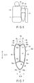
- FIG. 5 shows the deployed side airbag 30 cross-sectioned along line F5-F5 shown in FIG. 4.
- FIG. 5 illustrates only the side airbag 30 and illustrates neither the passenger seat 14 nor an occupant H seated in the passenger seat 14.
- a longitudinal direction A1, width direction B1, and vertical direction C1 of the side airbag 30 are defined.
- the various directions of the side airbag 30 are defined based on such an attitude that the side airbag 30 is inflated and deployed laterally relative to the seat.
- the various directions of the side airbag 30 described above are coincident with directions set for the passenger seat 14 (seat to which the side airbag device 20 is attached).
- a longitudinal direction, width direction, and vertical direction set for the passenger seat 14 are coincident with the vehicle-body longitudinal direction A, vehicle width direction B, and vehicle-body vertical direction C, respectively, defined for the vehicle body 17.
- the longitudinal direction A1, width direction B1, and vertical direction C1 of the side airbag 30 are coincident with A, B and C, respectively.
- the directions A1, B1 and C1 are perpendicular to one another.
- the various directions of the side airbag 30 are set based on a state where the seatback 16 is not reclined. In FIGS. 2 to 4 , the seatback 16 is not reclined.
- the side airbag 30 comprises a first base fabric 31 for use as a vehicle-body-side base fabric, second base fabric 32 as an occupant-side base fabric, third base fabric 33 as a top base fabric, partition cloth 34, and tether 35.
- the first and second base fabrics 31 and 32 are located opposite each other in the width direction B and have substantially the same shape and size. All areas of the first and second base fabrics 31 and 32 except the upper ends of their respective peripheral edges 31a and 32a are connected to one another. As an example of this connection structure, those areas are sewn together.
- the side airbag body 36 is in the form of an open-top bag.
- the side airbag body 36 is in the form of an open-top bag.
- the third base fabric 33 is disposed so as to close the top opening of the side airbag body 36.
- the whole area of a peripheral edge 33a of the third base fabric 33 is connected to the opening edge of the side airbag body 36.
- reference number 37 denotes a seam (joint) along which the side airbag body 36 and third base fabric 33 are sewn together.
- the seam 37 extends a predetermined length in the longitudinal direction A1.
- the predetermined length stated here is a sufficient length to enable an arm facing section 38 (described later) to support an arm H2.
- the partition cloth 34 divides the interior of the side airbag 30 into an upper compartment 45 and a lower compartment 46.
- the lower compartment 46 faces a lumbar region H1 of the occupant H.
- an entire peripheral edge 34a of the partition cloth 34 is sewn on the inner surfaces of the first and second base fabrics 31 and 32 throughout the circumference, whereby the interior of the side airbag 30 is divided into the upper and lower compartments 45 and 46.
- the tether 35 is in the form of a cord, one end 35a of which is secured to the center of the third base fabric 33 with respect to the longitudinal direction A1 as well as to the width direction B1.
- the one end 35a and third base fabric 33 are sewn together, for example.
- the other end 35b of the tether 35 is secured to the center of the partition cloth 34 with respect to the width direction B1 in a position behind the one end 35a with respect to the longitudinal direction A1.
- the other end 35b and partition cloth 34 are sewn together.
- the length of the tether 35 is set so that the tether 35 pulls down the center of the third base fabric 33 with respect to its width direction to cause the third base fabric 33 to be dented downward, as shown in FIG. 5 , when the side airbag 30 is inflated and deployed.
- the length of the tether 35 can be reduced so that the arm facing section 38 (described later) can be formed earlier.
- the tether is an example of a cord member according to the present invention.
- the occupant H is assumed to have the physique of the average Japanese adult, by way of example.
- the side airbag 30, which is inflated and deployed, as shown in FIG. 3 , is located outside the passenger seat 14 with respect to the vehicle width direction.
- the side airbag 30 When the occupant H is seated in the passenger seat 14, the side airbag 30 is disposed just beside the occupant H in a space between the occupant H and door member 6 (vehicle body 11). Further, the inflated and deployed side airbag 30 projects outward from that part of the seatback 16 which faces the arm H2 of the occupant H.
- the side airbag 30 When the side airbag 30 is fully deployed, the side airbag 30 pushes up the arm H2 of the occupant H from below, and the third base fabric 33 that constitutes a top portion faces the arm H2 from below.
- the arm facing section 38 is an example of an arm facing section according to the present invention.
- the third base fabric 33 is an example of a base fabric that forms the arm facing section according to the present invention.
- the one end 35a of the tether 35 is connected to that part of the third base fabric 33 which faces the center of the arm H2 with respect to its width direction.
- the width direction of the arm H2 is a direction of the arm H2 parallel to the width direction B1 of the side airbag device 20.
- the position of the center of the third base fabric 33 with respect to its width direction faces the center of the arm H2 with respect to its width direction.
- the one end 35a of the tether 35 is connected to the center of the third base fabric 33 with respect to the width direction B1.
- the inflated and deployed side airbag 30 has a size that covers the lumbar region H1 and the entire area of a chest region H3 of the occupant H. Further, the inflated and deployed side airbag 30 has such a size that the arm H2 that is pushed up by the dented arm facing section 38 is parallel or substantially parallel to the longitudinal direction A1, as shown in FIG. 4 .
- the arm H2 is set to be parallel or substantially parallel to the longitudinal direction in the present embodiment, it is not limited to this.
- the size of the side airbag 30 should only be such that the arm H2 is not located between the chest region H3 and side airbag 30 when the side airbag is inflated and deployed.
- the arm H2 may be pushed up above a position where it is parallel to the longitudinal direction. This is an example of a position where the arm does not overlap a chest region according to the present invention.
- the position of the bottom of the hollow is designated by P.
- P is in the center of the third base fabric with respect to the width direction B1.
- the bottom position P is indicated by a dotted line. The bottom position P extends in the longitudinal direction A1.
- the dent shape of the arm facing section 38 is kept in the longitudinal direction A1.
- the arm H2 of the occupant H is accommodated in this dent.
- the width of the third base fabric 33 is set so that the arm H2 can be accommodated.
- the other end 35b is located behind the one end 35a, the dent of the arm facing section 38 is formed mainly on the front side. This is because the arm H2 is located ahead of a shoulder H4. In other words, the positions of the ends 35a and 35b are set so that the dent shape is formed ahead of the shoulder H4 of the occupant H at the least.
- the inflated and deployed side airbag 30 has a width W that increases from bottom to top. Specifically, the width of that part of the side airbag 30 which faces the chest region H3 can be made larger, so that allowance for the absorption of impact applied to the chest region H3 can be made generous.
- the width W is set to be larger by virtue of the absence of the arm H2.
- the impact detection sensor 70 detects this impact.
- the impact detection sensor 70 is set such that it can detect, for example, impact of a preset magnitude or greater. If the impact detection sensor 70 detects impact, the igniter 60 is actuated. When the igniter 60 is actuated, the inflator 50 discharges gas. Consequently, the side airbag 30 is inflated and deployed.
- FIG. 6 is a diagram more schematically showing a state where the side airbag 30 is inflated and deployed.
- FIG. 6 shows an example in which the passenger seat is viewed from the front.
- the inflated and deployed side airbag 30 is located beside the chest region H3 of the occupant H. Since the side airbag 30 pushes up the arm H2, the arm H2 is not accommodated between the chest region H3 and side airbag 30.
- FIG. 6 shows a state after the door member 6 is moved so that it strikes the side airbag 30.
- the door member 6 is caused to project inward relative to the vehicle width by lateral impact, as shown in FIG. 3 , the impact is absorbed by the side airbag 30.
- the side airbag 30 pushes up the arm H2 of the occupant H so that the arm H2 is not accommodated between the chest region H3 and side airbag 30. Consequently, the width W of the side airbag 30, which is allowance for the absorption of impact, can be fully secured, so that the impact applied to the occupant H can be further reduced. Since the arm H2 is pushed up, moreover, the arm H2 cannot be pressed against the chest region H3, so that the impact cannot be applied to the chest region H3 through the arm H2.
- the arm facing section 38 is dented, furthermore, the arm H2 is accommodated into the dent in the process of inflation and deployment, so that the arm H2 can be smoothly pushed up without being disengaged from the side airbag 30.
- the side airbag device 20 has been described as being provided at the passenger seat 14, for example.
- the side airbag device 20 may alternatively be used for the driver seat or rear seat 13. Also in this case, the same effect as that of the present embodiment can be obtained.
- a side airbag according to a second embodiment of the present invention will now be described with reference to FIGS. 7 and 8 .
- Like reference numbers used in the first embodiment are used to designate configurations having the same functions as those of the first embodiment, and a description thereof is omitted.
- the present embodiment differs from the first embodiment in the structure of a side airbag 30.
- Other structures are the same as those of the first embodiment. The following is a specific description of the different structure.
- the structures of a side airbag device 20 of the present embodiment other than the side airbag 30 are the same as those of the first embodiment.
- FIG. 7 is a sectional view showing the side airbag 30 of the present embodiment in an inflated and deployed state, cross-sectioned in the width direction B1.
- the side airbag 30 comprises fourth and fifth base fabrics 80 and 81 in place of the first to third base fabrics 31 to 33.
- the fourth and fifth base fabrics 80 and 81 are located opposite each other in the width direction B1, and their respective peripheral edges 80a and 81a are entirely connected to each other. As an example of the mutual connection structure, those edges are sewn together.
- the fourth and fifth base fabrics 80 and 81 are an example of two base fabrics according to the present invention.
- a joint that is formed by connecting the peripheral edges 80a and 81a of the fourth and fifth base fabrics 80 and 81 is located, for example, on an imaginary plane that is defined by the longitudinal direction A1 and vertical direction C1.
- a seam that connects the fourth and fifth base fabrics 80 and 81 is located on the imaginary plane defined by the longitudinal direction A1 and vertical direction C1.
- FIG. 8 is a side view showing the side airbag 30 of the present embodiment in the inflated and deployed state, taken from the outside with respect to the width direction B1.
- a seam 82 as a joint along which the respective upper edges of the fourth and fifth base fabrics 80 and 81 are sewn together is designed to extend in the longitudinal direction A1 and face the center of the arm H2 when the side airbag 30 is inflated and deployed.
- the seam 82 like that of the first embodiment, is long enough to support the arm H2.
- One end 35a of a tether 35 is connected to the seam 82.
- the one end 35a and seam 82 are sewn together.
- a partition cloth 34 is connected to those parts of the fourth and fifth base fabrics 80 and 81 near the lumbar region H1 of the occupant H so as to divide a lower compartment 46 and upper compartment 45 in the inflated and deployed state.
- the connection structure and position of the partition cloth 34 are the same as those of the first embodiment.
- the other end 35a of the tether 34 like that of the first embodiment, is connected to the partition cloth 34.
- the positional relationship between the one end 35a and the other end 35b is the same as that of the first embodiment. Specifically, the other end 35b is located behind the one end 35a.
- a dent of an arm facing section 38 is formed mainly on the front side.
- the one end 35a and the other end 35b are set so that the dent shape of the arm facing section 38 is formed ahead of the shoulder H4 of the occupant H at the least.
- a top portion 83 of the fourth and fifth base fabrics 80 and 81 forms the arm facing section 38.
- the length of the tether 35 is set so that the arm facing section 38 is dented.
- Seams 84 and 85 that extend in the longitudinal direction A1 are formed near the seam 82 on the top of fourth and fifth base fabrics 80 and 81.
- the seams 84 and 85 stated here do not connect different base fabrics but sew threads on them.
- the seams 84 and 85 face an outer edge 86 of the arm H2 of the occupant H with respect to the width direction B1 (B).
- the seams 84 and 85 are set so as to face the outer edge 86.
- the seams 84 and 85 are an example of bending portions that are formed so that the fourth and fifth base fabrics 80 and 81 are turned back when the side airbag 30 is inflated and deployed.
- the seams 84 and 85 are an example of the bending portions. Alternatively, they may be formed so that their outside parts are turned back in positions where the fourth and fifth base fabrics 80 and 81 face the outer edge of the arm, or near positions opposite the outer edges of the arm, or near positions opposite the outer edges of the arm. Based on this structure, as in the first embodiment, the arm H2 can be accommodated at the arm facing section 38.
- the size and shape of the inflated and deployed side airbag 30 are the same as those of the side airbag 30 that are constructed using the first to third base fabrics 31 and 33 of the first embodiment.
- the side airbag device 20 is constructed in the same manner as the first embodiment except for the side airbag 30 described above.
- the side airbag 30 is deployed in the same manner as in the first embodiment.
- the deployed side airbag 30 of the present embodiment like that of the first embodiment, pushes up the arm H2 of the occupant H to an up position where it does not overlap the chest region H3 in the width direction B1.
- a side airbag according to a third embodiment of the present invention will now be described with reference to FIG. 9 .
- Like reference numbers used in the first embodiment are used to designate configurations having the same functions as those of the first embodiment, and a description thereof is omitted.
- the present embodiment differs from the first embodiment in the structure of a side airbag 30.
- Other structures are the same as those of the first embodiment. The following is a specific description of the different structure.
- the structures of a side airbag device 20 of the present embodiment other than the side airbag 30 are the same as those of the first embodiment.
- FIG. 9 is a sectional view showing the side airbag 30 of the present embodiment in an inflated and deployed state, cross-sectioned in the width direction B1.
- the side airbag 30 comprises sixth to ninth base fabrics 90, 91, 92 and 93, in place of the first to third base fabrics 31 to 33, and tether 35.
- the sixth and seventh base fabrics 90 and 91 are located opposite each other in the width direction B1.
- the respective front and rear edges of the sixth and seventh are connected to one another.
- those edges are sewn together.
- the entire peripheral edge of the eighth base fabric 92 is connected to upper edges 90a and 91a of the sixth and seventh base fabrics 90 and 91.
- those edges are sewn together.
- the entire peripheral edge of the ninth base fabric 93 is connected to lower edges 90b and 91b of the sixth and seventh base fabrics 90 and 91.
- those edges are sewn together.
- a seam 100 between the sixth and eighth base fabrics 90 and 92 extends in the longitudinal direction A1.
- a seam 101 between the seventh and eighth base fabrics 90 and 92 extends in the longitudinal direction A1.
- the seams 100 and 101 are long enough to support the arm H2.
- the side airbag 30 is formed as a bag as the sixth to ninth base fabrics 90 to 93 are sewn together in the above-described manner.
- the eighth base fabric 92 forms an arm facing section 38.
- One end 35a of the tether 35 is connected to that part (e.g., the center with respect to the width direction B1 of the arm according to the present embodiment) of the eighth base fabric 92 which faces the center of the arm H2 of the occupant H.
- the other end 35b of the tether 35 is connected to the ninth base fabric 93.
- the length of the tether 35 is set so that the arm facing section 38 is dented so as to accommodate the arm H2 when the side airbag 30 is inflated and deployed.
- a bottom position P extends in the longitudinal direction A1.
- the eighth base fabric 92 is large enough to accommodate the arm H2.
- the side airbag 30 When the side airbag 30 is inflated and deployed, it is pulled by the tether 35, and the seams 100 and 101 between the ninth base fabric 93 and the sixth and seventh base fabrics 90 and 91 project outward, so that the arm facing section 38, like that of the first embodiment, is dented.
- the dent shape is maintained in the longitudinal direction A1.
- the interior of the side airbag 30 is not divided into upper and lower compartments 45 and 46. Further, lower edges 90b and 91b of the sixth and seventh base fabrics 90 and 91 and the ninth base fabric 93 are connected.
- a width w of that part of it which faces the lumbar region H1 of the occupant H can be fully secured. In other words, allowance for the absorption of impact applied to the lumbar region H1 can be made generous.
- the side airbag device 20 is constructed in the same manner as the first embodiment except for the side airbag 30 described above.
- the side airbag 30 is deployed in the same manner as in the first embodiment.
- the deployed side airbag 30 of the present embodiment like that of the first embodiment, pushes up the arm H2 of the occupant H to an up position where it does not overlap the chest region H3 in the width direction B1.
- the longitudinal positional relationship between the one end 35a and the other end 35b of the tether 35 is the same as that of the first embodiment.
- the other end 35b is located behind the one end 35a.
- a dent of the arm facing section 38 is formed mainly on the front side.
- the one end 35a and the other end 35b are set so that the dent shape of the arm facing section 38 is formed ahead of the shoulder H4 of the occupant H at the least.
- impact applied to the lumbar region H1 of the occupant H can be further absorbed, in addition to the same effect as that of the first embodiment.
- a side airbag according to a fourth embodiment of the present invention will now be described with reference to FIG. 10 .
- Like reference numbers used in the second embodiment are used to designate configurations having the same functions as those of the second embodiment, and a description thereof is omitted.
- the present embodiment differs from the second embodiment in the structure of a side airbag 30.
- the structures of a side airbag device 20 other than the side airbag 30 are the same as those of the second embodiment. The following is a specific description of the different structure.
- the side airbag 30 of the present embodiment differs from the side airbag 30 described in connection with the second embodiment in that it does not comprise a partition cloth 34 and in the region to which the other end 35b of a tether 35 is secured.
- the structures of the side airbag 30 of the present embodiment other than the above-described structures are the same as those of the side airbag 30 of the second embodiment.
- FIG. 10 shows the side airbag 30 of the present embodiment, cross-sectioned in the same manner as in FIG. 5 showing the first embodiment.
- the side airbag 30 of the present embodiment does not comprise the partition cloth 34.
- One end 35a of the tether 35 like that of the second embodiment, is connected to a seam 82 along which the respective upper ends of peripheral edges 80a and 81 of fourth and fifth base fabrics 80 and 81 are connected to each other. As an example of this connection structure, those edges are sewn together.
- the other end 35b of the tether 35 is connected to a seam 82a along which the respective lower ends of the peripheral edges 80a and 81a of the fourth and fifth base fabrics 80 and 81 are sewn together at the seam as the joint that connect the peripheral edges 80a and 81a.
- the other end 35b is connected to both the fourth and fifth base fabrics 80 and 81.
- those edges are sewn together.
- the positional relationship between the one end 35a and the other end 35b in the longitudinal direction A1 is the same as in the first and second embodiments. Specifically, the other end 35b is located behind the one end 35a.
- a dent of an arm facing section 38 is formed mainly on the front side. The one end 35a and the other end 35b are set so that the dent shape of the arm facing section 38 is formed ahead of the shoulder H4 of the occupant H at the least.
- the deployed side airbag 30 of the present embodiment pushes up the arm H2 of the occupant H to an up position where it does not overlap the chest region H3 in the width direction B1.
- the other end 35b of the tether 35 is connected to the seam 82a as a joint between the fourth and fifth base fabrics 80 and 81, whereby it is connected to both the fourth and fifth base fabrics 80 and 81.
- the other end 35b may be secured to the fourth base fabric 80 only. In this case, the other end 35b should only be secured to that part of the fourth base fabric 80 which is located below the one end 35a.
- the other end 35b may be connected to the fifth base fabric 81 only. In this case, the other end 35b should only be secured to that part of the fifth base fabric 81 which is located below the one end 35a.
- the other end 35b may be connected to both the fourth and fifth base fabrics 80 and 81 by the partition cloth 34.
- the other end 35b should only be connected to the fourth base fabric 80, as an example of the vehicle-body-side base fabric according to the present invention, and/or a fifth base fabric 81, as an example of the occupant-side base fabric according to the present invention. Even in the case that the other end 35b is secured to at least one of the fourth and fifth base fabrics 80 and 81, the one end 35a and the other end 35b should preferably be set so that the dent shape of the arm facing section 38 is formed ahead of the shoulder H4 of the occupant H at the least.
- the occupant H is assumed to have the physique of the average Japanese adult.
- the side airbag 30 is formed adaptively to the occupant H.
- the occupant H is not bound to be formed adaptively to the physique of the average Japanese adult.
- the side airbag 30 may be shaped to fit the body of an occupant of a country where an apparatus (vehicle or automobile) mounted with the side airbag device 20 is used. Also in this case, the deployed side airbag 30 pushes up the arm H2 of the occupant H to a position where it does not overlap the chest region H3 in the width direction B1.
- the single partition cloth 34 is used to divide the interior of the side airbag 30 into two parts, an upper compartment 45 and lower compartment 46.
- the partition cloth should only be able to divide the interior of the side airbag 30 into at least upper and lower compartments.
- the partition cloth may be designed to divide the interior of the side airbag into, for example, the upper and lower compartments and one or more additional compartments.
- the interior of the side airbag 30 is divided into the upper compartment 45, lower compartment 46, and one or more additional compartments.
- the other end 35b of the tether 35 should only be secured to the partition cloth.
- a plurality of partition cloths may be used to divide the interior of the side airbag 30 into three or more compartments as described above.
- the other end 35b of the tether 35 is secured to at least one of the plurality of partition cloths.
- the positional relationship between the one end 35a and the other end 35 of the tether 35 in the longitudinal direction A1 is the same as in the first and second embodiments, so that the same effect as those of the first and second embodiments can be obtained.
- the side airbag device 20 is provided at the passenger seat, by way of example. However, this is not limitative.
- the side airbag device 20 may be provided at the vehicle body 17.
- the side airbag devices 20 described in connection with the first to fourth embodiments may be provided at the door member 6.
- the position and attitude of the deployed side airbag 30 relative to the seat are the same as in the first to fourth embodiments.
- the longitudinal, vertical, and width directions of the side airbag 30 are coincident with the longitudinal, transverse, and vertical directions, respectively, of the seat that faces the deployed side airbag 30.
- the longitudinal, vertical, and width directions of the side airbag 30 are coincident with the longitudinal, transverse, and vertical directions, respectively, of the passenger seat 14, that is, the vehicle-body longitudinal direction, vehicle width direction, and vehicle-body vertical direction, respectively.
- the airbag body 36 and third base fabric 33 form an airbag unit 200.
- the side airbag 30 is configured to comprise the airbag unit 200, tether 35, and partition cloth 34.
- the side airbag 30 comprises an airbag unit 200 and the tether 35.
- the fourth and fifth base fabrics 80 and 81 form an airbag unit 200.
- the side airbag 30 comprises the airbag unit 200, partition cloth 34, and tether 35.
- the six, seventh, eighth, and ninth base fabrics 90 to 93 form an airbag unit 200.
- the side airbag 30 comprises the airbag unit and tether 35.
- the airbag unit 200 described above defines the outline of the side airbag 30.
- the side airbag 30 is deployed as gas is injected into the airbag unit 200.
- the airbag and the airbag unit are equivalent in the case that the side airbag 30 comprises neither the tether 35 nor the partition cloth 34 and is formed only of a member such as a base fabric that defines the outline of the side airbag 30.
Landscapes
- Engineering & Computer Science (AREA)
- Mechanical Engineering (AREA)
- Air Bags (AREA)
Applications Claiming Priority (2)
| Application Number | Priority Date | Filing Date | Title |
|---|---|---|---|
| JP2010004388 | 2010-01-12 | ||
| PCT/JP2011/050379 WO2011087026A1 (ja) | 2010-01-12 | 2011-01-12 | サイドエアバッグ |
Publications (3)
| Publication Number | Publication Date |
|---|---|
| EP2481642A1 true EP2481642A1 (de) | 2012-08-01 |
| EP2481642A4 EP2481642A4 (de) | 2013-03-27 |
| EP2481642B1 EP2481642B1 (de) | 2014-11-12 |
Family
ID=44304299
Family Applications (1)
| Application Number | Title | Priority Date | Filing Date |
|---|---|---|---|
| EP11732896.3A Not-in-force EP2481642B1 (de) | 2010-01-12 | 2011-01-12 | Seitenairbag |
Country Status (4)
| Country | Link |
|---|---|
| US (1) | US8616579B2 (de) |
| EP (1) | EP2481642B1 (de) |
| JP (1) | JP5445595B2 (de) |
| WO (1) | WO2011087026A1 (de) |
Cited By (1)
| Publication number | Priority date | Publication date | Assignee | Title |
|---|---|---|---|---|
| WO2015124299A1 (en) * | 2014-02-20 | 2015-08-27 | Dalphi Metal Espana, S.A. | Thorax occupant protection device and method of protecting the thorax of a vehicle occupant in side impacts |
Families Citing this family (24)
| Publication number | Priority date | Publication date | Assignee | Title |
|---|---|---|---|---|
| DE102009019766A1 (de) * | 2009-04-28 | 2010-01-28 | Takata-Petri Ag | Gassack für ein Fahrzeuginsassen-Rückhaltesystem und Verfahren zum Herstellen eines Fahrzeuginsassen-Rückhaltesystems |
| JP5807567B2 (ja) * | 2012-01-30 | 2015-11-10 | トヨタ自動車株式会社 | 車両用サイドエアバッグ装置 |
| RU2584325C1 (ru) | 2012-04-17 | 2016-05-20 | Тойота Дзидося Кабусики Кайся | Устройство боковой подушки безопасности для транспортного средства |
| JP5831634B2 (ja) * | 2012-06-06 | 2015-12-09 | トヨタ自動車株式会社 | 車両用サイドエアバッグ装置 |
| WO2014033820A1 (ja) * | 2012-08-27 | 2014-03-06 | トヨタ自動車株式会社 | 車両用サイドエアバッグ装置 |
| JP5895872B2 (ja) * | 2013-02-26 | 2016-03-30 | トヨタ自動車株式会社 | 車両用サイドエアバッグ装置 |
| US9598043B2 (en) * | 2013-08-06 | 2017-03-21 | Autoliv Development Ab | Side airbag device for vehicles |
| DE102013015141B4 (de) * | 2013-09-13 | 2017-08-10 | Trw Automotive Gmbh | Verfahren zum Schützen eines Fahrzeuginsassen sowie Gassack |
| JP5949712B2 (ja) * | 2013-09-18 | 2016-07-13 | トヨタ自動車株式会社 | 車両用サイドエアバッグ装置及び車両用シート |
| JP6217330B2 (ja) * | 2013-11-12 | 2017-10-25 | 三菱自動車工業株式会社 | サイドエアバッグ装置 |
| US8967665B1 (en) * | 2014-01-23 | 2015-03-03 | GM Global Technology Operations LLC | Inflatable cushion for a side-impact airbag |
| US9505369B2 (en) * | 2014-09-12 | 2016-11-29 | Toyoda Gosei Co., Ltd. | Side airbag apparatus |
| JP6428141B2 (ja) * | 2014-10-17 | 2018-11-28 | 三菱自動車工業株式会社 | サイドエアバッグ装置 |
| US9592788B2 (en) * | 2015-01-14 | 2017-03-14 | GM Global Technology Operations LLC | Front center airbag lower chamber and panel |
| WO2016158022A1 (ja) | 2015-03-30 | 2016-10-06 | オートリブ ディベロップメント エービー | 車両用サイドエアバッグ装置 |
| JP6372041B2 (ja) * | 2015-09-24 | 2018-08-15 | オートリブ ディベロップメント エービー | サイドエアバッグ装置 |
| JP6631957B2 (ja) * | 2016-03-31 | 2020-01-15 | 株式会社Subaru | 車両の乗員保護装置 |
| JP6631958B2 (ja) * | 2016-03-31 | 2020-01-15 | 株式会社Subaru | 車両の乗員保護装置 |
| JP6626763B2 (ja) * | 2016-03-31 | 2019-12-25 | 株式会社Subaru | 車両の乗員保護装置 |
| JP6631956B2 (ja) * | 2016-03-31 | 2020-01-15 | 株式会社Subaru | 車両の乗員保護装置 |
| JP6626764B2 (ja) * | 2016-03-31 | 2019-12-25 | 株式会社Subaru | 車両の乗員保護装置 |
| JP6738646B2 (ja) * | 2016-04-27 | 2020-08-12 | マツダ株式会社 | サイドエアバッグ装置 |
| JP6543650B2 (ja) * | 2017-03-31 | 2019-07-10 | 株式会社Subaru | 車両の乗員保護装置 |
| US11208070B1 (en) | 2020-10-15 | 2021-12-28 | Ford Global Technologies, Llc | Airbag system and method(s) of use thereof |
Citations (5)
| Publication number | Priority date | Publication date | Assignee | Title |
|---|---|---|---|---|
| US20070216142A1 (en) * | 2006-03-15 | 2007-09-20 | Honda Motor Co., Ltd. | Airbag device for vehicle |
| US20080252054A1 (en) * | 2007-04-16 | 2008-10-16 | Hyundai Mobis Co., Ltd. | Air bag cushion |
| DE102008048398A1 (de) * | 2008-09-19 | 2009-02-19 | Takata-Petri Ag | Gassack für ein Kraftfahrzeug |
| DE102009007179A1 (de) * | 2008-12-18 | 2009-07-09 | Takata-Petri Ag | Gassackanordnung für ein Fahrzeuginsassen-Rückhaltesystem und Verfahren zum Schützen eines Fahrzeuginsassen |
| WO2012009049A1 (en) * | 2010-07-14 | 2012-01-19 | Autoliv Asp, Inc. | Inflatable airbag assemblies with arm-manipulating side airbags |
Family Cites Families (19)
| Publication number | Priority date | Publication date | Assignee | Title |
|---|---|---|---|---|
| JP3353565B2 (ja) | 1995-09-25 | 2002-12-03 | トヨタ自動車株式会社 | シート組込み式の側突用エアバッグ装置 |
| JP2962225B2 (ja) * | 1996-04-08 | 1999-10-12 | 三菱自動車工業株式会社 | 側面衝突用エアバッグ |
| JP2000280853A (ja) * | 1999-03-30 | 2000-10-10 | Toyota Central Res & Dev Lab Inc | 側突用エアバッグ装置 |
| JP4168283B2 (ja) * | 2003-01-20 | 2008-10-22 | トヨタ自動車株式会社 | 乗員保護装置 |
| JP4313641B2 (ja) | 2003-10-17 | 2009-08-12 | 本田技研工業株式会社 | サイドエアバッグ装置 |
| JP4552840B2 (ja) * | 2005-04-01 | 2010-09-29 | 豊田合成株式会社 | サイドエアバッグ装置 |
| DE102005025553A1 (de) * | 2005-06-01 | 2006-12-07 | Autoliv Development Ab | Airbaganordnung |
| US7448645B2 (en) * | 2006-03-31 | 2008-11-11 | Ford Global Technologies, Llc | Contoured side impact airbag |
| JP5120599B2 (ja) * | 2006-06-20 | 2013-01-16 | マツダ株式会社 | サイドエアバッグ装置 |
| JP4793123B2 (ja) | 2006-06-21 | 2011-10-12 | 豊田合成株式会社 | サイドエアバッグ装置 |
| JP2008189132A (ja) * | 2007-02-05 | 2008-08-21 | Toyoda Gosei Co Ltd | サイドエアバッグ装置 |
| US7766379B2 (en) * | 2007-09-24 | 2010-08-03 | Nissan Technical Center North America, Inc. | Side airbag apparatus and method |
| JP5035004B2 (ja) * | 2008-02-18 | 2012-09-26 | 豊田合成株式会社 | 側突用エアバッグ装置 |
| JP2010132072A (ja) * | 2008-12-03 | 2010-06-17 | Toyota Motor Corp | 車両用サイドエアバッグ装置 |
| US7837226B2 (en) * | 2008-12-09 | 2010-11-23 | Toyoda Gosei Co., Ltd. | Airbag apparatus |
| JP4892572B2 (ja) * | 2009-02-12 | 2012-03-07 | トヨタ自動車株式会社 | サイドエアバッグ装置及びサイドエアバッグの製造方法 |
| JP2011057143A (ja) * | 2009-09-11 | 2011-03-24 | Fuji Heavy Ind Ltd | サイドエアバッグ装置 |
| JP5401495B2 (ja) * | 2011-03-17 | 2014-01-29 | 富士重工業株式会社 | サイドエアバッグ装置、乗員保護装置及び乗員保護方法 |
| JP5598393B2 (ja) * | 2011-03-22 | 2014-10-01 | 豊田合成株式会社 | サイドエアバッグ装置 |
-
2011
- 2011-01-12 WO PCT/JP2011/050379 patent/WO2011087026A1/ja active Application Filing
- 2011-01-12 US US13/496,450 patent/US8616579B2/en not_active Expired - Fee Related
- 2011-01-12 EP EP11732896.3A patent/EP2481642B1/de not_active Not-in-force
- 2011-01-12 JP JP2011549991A patent/JP5445595B2/ja not_active Expired - Fee Related
Patent Citations (5)
| Publication number | Priority date | Publication date | Assignee | Title |
|---|---|---|---|---|
| US20070216142A1 (en) * | 2006-03-15 | 2007-09-20 | Honda Motor Co., Ltd. | Airbag device for vehicle |
| US20080252054A1 (en) * | 2007-04-16 | 2008-10-16 | Hyundai Mobis Co., Ltd. | Air bag cushion |
| DE102008048398A1 (de) * | 2008-09-19 | 2009-02-19 | Takata-Petri Ag | Gassack für ein Kraftfahrzeug |
| DE102009007179A1 (de) * | 2008-12-18 | 2009-07-09 | Takata-Petri Ag | Gassackanordnung für ein Fahrzeuginsassen-Rückhaltesystem und Verfahren zum Schützen eines Fahrzeuginsassen |
| WO2012009049A1 (en) * | 2010-07-14 | 2012-01-19 | Autoliv Asp, Inc. | Inflatable airbag assemblies with arm-manipulating side airbags |
Non-Patent Citations (1)
| Title |
|---|
| See also references of WO2011087026A1 * |
Cited By (2)
| Publication number | Priority date | Publication date | Assignee | Title |
|---|---|---|---|---|
| WO2015124299A1 (en) * | 2014-02-20 | 2015-08-27 | Dalphi Metal Espana, S.A. | Thorax occupant protection device and method of protecting the thorax of a vehicle occupant in side impacts |
| US10173631B2 (en) | 2014-02-20 | 2019-01-08 | Dalphi Metal Espana S.A. | Thorax occupant protection device and method of protecting the thorax of a vehicle occupant in side impacts |
Also Published As
| Publication number | Publication date |
|---|---|
| JPWO2011087026A1 (ja) | 2013-05-20 |
| EP2481642A4 (de) | 2013-03-27 |
| CN102574497A (zh) | 2012-07-11 |
| JP5445595B2 (ja) | 2014-03-19 |
| US8616579B2 (en) | 2013-12-31 |
| EP2481642B1 (de) | 2014-11-12 |
| US20120175925A1 (en) | 2012-07-12 |
| WO2011087026A1 (ja) | 2011-07-21 |
Similar Documents
| Publication | Publication Date | Title |
|---|---|---|
| EP2481642B1 (de) | Seitenairbag | |
| CN108068745B (zh) | 包括安全气囊的车辆座椅总成 | |
| JP6561942B2 (ja) | サイドエアバッグ装置を搭載した車両用シート | |
| CN108944772B (zh) | 具有磁性元件的车辆安全气囊系统和方法 | |
| JP6428929B2 (ja) | 乗員保護装置 | |
| JP5754436B2 (ja) | 車両用乗員拘束システム | |
| KR102004535B1 (ko) | 승차인 보호 장치 | |
| JP5817933B2 (ja) | 車両用サイドエアバッグ装置 | |
| US7695012B2 (en) | Airbag systems with a split pocket | |
| JP5776733B2 (ja) | 車両用サイドエアバッグ装置 | |
| JP5534708B2 (ja) | サイドエアバッグ装置およびそのバッグ部の折畳み方法 | |
| CN105073510B (zh) | 内置侧气囊的车辆用座椅 | |
| US20140008902A1 (en) | Airbag with low-volume structure | |
| JP5408092B2 (ja) | サイドエアバッグ装置 | |
| KR20220002684A (ko) | 사이드 에어백 장치 및 사이드 에어백 장치의 제조 방법 | |
| JP2010052619A (ja) | エアバッグ装置 | |
| JP6036450B2 (ja) | ファーサイド乗員拘束装置及び車両用シート | |
| JP2015020509A (ja) | 車両用センターエアバッグ装置及び車両用乗員保護装置 | |
| JP2017149178A (ja) | サイドエアバッグ装置 | |
| JP6737165B2 (ja) | 車両用乗員拘束装置 | |
| JP7098546B2 (ja) | エアバッグシステム | |
| CN109795440B (zh) | 车辆用侧气囊装置 | |
| JP2017185953A (ja) | 乗員保護装置 | |
| JP6748293B2 (ja) | サイドエアバッグ装置 | |
| JP2011168128A (ja) | エアバッグ装置 |
Legal Events
| Date | Code | Title | Description |
|---|---|---|---|
| PUAI | Public reference made under article 153(3) epc to a published international application that has entered the european phase |
Free format text: ORIGINAL CODE: 0009012 |
|
| 17P | Request for examination filed |
Effective date: 20120322 |
|
| AK | Designated contracting states |
Kind code of ref document: A1 Designated state(s): AL AT BE BG CH CY CZ DE DK EE ES FI FR GB GR HR HU IE IS IT LI LT LU LV MC MK MT NL NO PL PT RO RS SE SI SK SM TR |
|
| RIN1 | Information on inventor provided before grant (corrected) |
Inventor name: FUJISAWA, NAOKI Inventor name: SUZUKI, HIROYUKI |
|
| A4 | Supplementary search report drawn up and despatched |
Effective date: 20130221 |
|
| RIC1 | Information provided on ipc code assigned before grant |
Ipc: B60R 21/2338 20110101AFI20130215BHEP Ipc: B60R 21/233 20060101ALI20130215BHEP Ipc: B60R 21/231 20110101ALI20130215BHEP Ipc: B60R 21/207 20060101ALI20130215BHEP |
|
| DAX | Request for extension of the european patent (deleted) | ||
| 17Q | First examination report despatched |
Effective date: 20130930 |
|
| GRAP | Despatch of communication of intention to grant a patent |
Free format text: ORIGINAL CODE: EPIDOSNIGR1 |
|
| INTG | Intention to grant announced |
Effective date: 20140528 |
|
| GRAS | Grant fee paid |
Free format text: ORIGINAL CODE: EPIDOSNIGR3 |
|
| GRAA | (expected) grant |
Free format text: ORIGINAL CODE: 0009210 |
|
| AK | Designated contracting states |
Kind code of ref document: B1 Designated state(s): AL AT BE BG CH CY CZ DE DK EE ES FI FR GB GR HR HU IE IS IT LI LT LU LV MC MK MT NL NO PL PT RO RS SE SI SK SM TR |
|
| REG | Reference to a national code |
Ref country code: GB Ref legal event code: FG4D |
|
| REG | Reference to a national code |
Ref country code: CH Ref legal event code: EP |
|
| REG | Reference to a national code |
Ref country code: AT Ref legal event code: REF Ref document number: 695535 Country of ref document: AT Kind code of ref document: T Effective date: 20141115 |
|
| REG | Reference to a national code |
Ref country code: IE Ref legal event code: FG4D |
|
| REG | Reference to a national code |
Ref country code: DE Ref legal event code: R096 Ref document number: 602011011321 Country of ref document: DE Effective date: 20141224 |
|
| REG | Reference to a national code |
Ref country code: NL Ref legal event code: VDEP Effective date: 20141112 |
|
| REG | Reference to a national code |
Ref country code: AT Ref legal event code: MK05 Ref document number: 695535 Country of ref document: AT Kind code of ref document: T Effective date: 20141112 |
|
| PG25 | Lapsed in a contracting state [announced via postgrant information from national office to epo] |
Ref country code: NO Free format text: LAPSE BECAUSE OF FAILURE TO SUBMIT A TRANSLATION OF THE DESCRIPTION OR TO PAY THE FEE WITHIN THE PRESCRIBED TIME-LIMIT Effective date: 20150212 Ref country code: FI Free format text: LAPSE BECAUSE OF FAILURE TO SUBMIT A TRANSLATION OF THE DESCRIPTION OR TO PAY THE FEE WITHIN THE PRESCRIBED TIME-LIMIT Effective date: 20141112 Ref country code: IS Free format text: LAPSE BECAUSE OF FAILURE TO SUBMIT A TRANSLATION OF THE DESCRIPTION OR TO PAY THE FEE WITHIN THE PRESCRIBED TIME-LIMIT Effective date: 20150312 Ref country code: LT Free format text: LAPSE BECAUSE OF FAILURE TO SUBMIT A TRANSLATION OF THE DESCRIPTION OR TO PAY THE FEE WITHIN THE PRESCRIBED TIME-LIMIT Effective date: 20141112 Ref country code: NL Free format text: LAPSE BECAUSE OF FAILURE TO SUBMIT A TRANSLATION OF THE DESCRIPTION OR TO PAY THE FEE WITHIN THE PRESCRIBED TIME-LIMIT Effective date: 20141112 Ref country code: PT Free format text: LAPSE BECAUSE OF FAILURE TO SUBMIT A TRANSLATION OF THE DESCRIPTION OR TO PAY THE FEE WITHIN THE PRESCRIBED TIME-LIMIT Effective date: 20150312 Ref country code: ES Free format text: LAPSE BECAUSE OF FAILURE TO SUBMIT A TRANSLATION OF THE DESCRIPTION OR TO PAY THE FEE WITHIN THE PRESCRIBED TIME-LIMIT Effective date: 20141112 |
|
| PG25 | Lapsed in a contracting state [announced via postgrant information from national office to epo] |
Ref country code: CY Free format text: LAPSE BECAUSE OF FAILURE TO SUBMIT A TRANSLATION OF THE DESCRIPTION OR TO PAY THE FEE WITHIN THE PRESCRIBED TIME-LIMIT Effective date: 20141112 Ref country code: AT Free format text: LAPSE BECAUSE OF FAILURE TO SUBMIT A TRANSLATION OF THE DESCRIPTION OR TO PAY THE FEE WITHIN THE PRESCRIBED TIME-LIMIT Effective date: 20141112 Ref country code: RS Free format text: LAPSE BECAUSE OF FAILURE TO SUBMIT A TRANSLATION OF THE DESCRIPTION OR TO PAY THE FEE WITHIN THE PRESCRIBED TIME-LIMIT Effective date: 20141112 Ref country code: GR Free format text: LAPSE BECAUSE OF FAILURE TO SUBMIT A TRANSLATION OF THE DESCRIPTION OR TO PAY THE FEE WITHIN THE PRESCRIBED TIME-LIMIT Effective date: 20150213 Ref country code: LV Free format text: LAPSE BECAUSE OF FAILURE TO SUBMIT A TRANSLATION OF THE DESCRIPTION OR TO PAY THE FEE WITHIN THE PRESCRIBED TIME-LIMIT Effective date: 20141112 Ref country code: PL Free format text: LAPSE BECAUSE OF FAILURE TO SUBMIT A TRANSLATION OF THE DESCRIPTION OR TO PAY THE FEE WITHIN THE PRESCRIBED TIME-LIMIT Effective date: 20141112 Ref country code: SE Free format text: LAPSE BECAUSE OF FAILURE TO SUBMIT A TRANSLATION OF THE DESCRIPTION OR TO PAY THE FEE WITHIN THE PRESCRIBED TIME-LIMIT Effective date: 20141112 Ref country code: HR Free format text: LAPSE BECAUSE OF FAILURE TO SUBMIT A TRANSLATION OF THE DESCRIPTION OR TO PAY THE FEE WITHIN THE PRESCRIBED TIME-LIMIT Effective date: 20141112 |
|
| PG25 | Lapsed in a contracting state [announced via postgrant information from national office to epo] |
Ref country code: CZ Free format text: LAPSE BECAUSE OF FAILURE TO SUBMIT A TRANSLATION OF THE DESCRIPTION OR TO PAY THE FEE WITHIN THE PRESCRIBED TIME-LIMIT Effective date: 20141112 Ref country code: SK Free format text: LAPSE BECAUSE OF FAILURE TO SUBMIT A TRANSLATION OF THE DESCRIPTION OR TO PAY THE FEE WITHIN THE PRESCRIBED TIME-LIMIT Effective date: 20141112 Ref country code: RO Free format text: LAPSE BECAUSE OF FAILURE TO SUBMIT A TRANSLATION OF THE DESCRIPTION OR TO PAY THE FEE WITHIN THE PRESCRIBED TIME-LIMIT Effective date: 20141112 Ref country code: EE Free format text: LAPSE BECAUSE OF FAILURE TO SUBMIT A TRANSLATION OF THE DESCRIPTION OR TO PAY THE FEE WITHIN THE PRESCRIBED TIME-LIMIT Effective date: 20141112 Ref country code: DK Free format text: LAPSE BECAUSE OF FAILURE TO SUBMIT A TRANSLATION OF THE DESCRIPTION OR TO PAY THE FEE WITHIN THE PRESCRIBED TIME-LIMIT Effective date: 20141112 |
|
| REG | Reference to a national code |
Ref country code: DE Ref legal event code: R097 Ref document number: 602011011321 Country of ref document: DE |
|
| REG | Reference to a national code |
Ref country code: CH Ref legal event code: PL |
|
| PG25 | Lapsed in a contracting state [announced via postgrant information from national office to epo] |
Ref country code: LU Free format text: LAPSE BECAUSE OF FAILURE TO SUBMIT A TRANSLATION OF THE DESCRIPTION OR TO PAY THE FEE WITHIN THE PRESCRIBED TIME-LIMIT Effective date: 20150112 |
|
| PLBE | No opposition filed within time limit |
Free format text: ORIGINAL CODE: 0009261 |
|
| STAA | Information on the status of an ep patent application or granted ep patent |
Free format text: STATUS: NO OPPOSITION FILED WITHIN TIME LIMIT |
|
| PG25 | Lapsed in a contracting state [announced via postgrant information from national office to epo] |
Ref country code: MC Free format text: LAPSE BECAUSE OF FAILURE TO SUBMIT A TRANSLATION OF THE DESCRIPTION OR TO PAY THE FEE WITHIN THE PRESCRIBED TIME-LIMIT Effective date: 20141112 |
|
| 26N | No opposition filed |
Effective date: 20150813 |
|
| GBPC | Gb: european patent ceased through non-payment of renewal fee |
Effective date: 20150212 |
|
| PG25 | Lapsed in a contracting state [announced via postgrant information from national office to epo] |
Ref country code: LI Free format text: LAPSE BECAUSE OF NON-PAYMENT OF DUE FEES Effective date: 20150131 Ref country code: CH Free format text: LAPSE BECAUSE OF NON-PAYMENT OF DUE FEES Effective date: 20150131 |
|
| REG | Reference to a national code |
Ref country code: IE Ref legal event code: MM4A |
|
| PG25 | Lapsed in a contracting state [announced via postgrant information from national office to epo] |
Ref country code: IT Free format text: LAPSE BECAUSE OF FAILURE TO SUBMIT A TRANSLATION OF THE DESCRIPTION OR TO PAY THE FEE WITHIN THE PRESCRIBED TIME-LIMIT Effective date: 20141112 |
|
| REG | Reference to a national code |
Ref country code: FR Ref legal event code: PLFP Year of fee payment: 6 |
|
| PG25 | Lapsed in a contracting state [announced via postgrant information from national office to epo] |
Ref country code: IE Free format text: LAPSE BECAUSE OF NON-PAYMENT OF DUE FEES Effective date: 20150112 Ref country code: GB Free format text: LAPSE BECAUSE OF NON-PAYMENT OF DUE FEES Effective date: 20150212 |
|
| PG25 | Lapsed in a contracting state [announced via postgrant information from national office to epo] |
Ref country code: SI Free format text: LAPSE BECAUSE OF FAILURE TO SUBMIT A TRANSLATION OF THE DESCRIPTION OR TO PAY THE FEE WITHIN THE PRESCRIBED TIME-LIMIT Effective date: 20141112 |
|
| REG | Reference to a national code |
Ref country code: FR Ref legal event code: PLFP Year of fee payment: 7 |
|
| PG25 | Lapsed in a contracting state [announced via postgrant information from national office to epo] |
Ref country code: MT Free format text: LAPSE BECAUSE OF FAILURE TO SUBMIT A TRANSLATION OF THE DESCRIPTION OR TO PAY THE FEE WITHIN THE PRESCRIBED TIME-LIMIT Effective date: 20141112 |
|
| PG25 | Lapsed in a contracting state [announced via postgrant information from national office to epo] |
Ref country code: SM Free format text: LAPSE BECAUSE OF FAILURE TO SUBMIT A TRANSLATION OF THE DESCRIPTION OR TO PAY THE FEE WITHIN THE PRESCRIBED TIME-LIMIT Effective date: 20141112 Ref country code: BG Free format text: LAPSE BECAUSE OF FAILURE TO SUBMIT A TRANSLATION OF THE DESCRIPTION OR TO PAY THE FEE WITHIN THE PRESCRIBED TIME-LIMIT Effective date: 20141112 Ref country code: HU Free format text: LAPSE BECAUSE OF FAILURE TO SUBMIT A TRANSLATION OF THE DESCRIPTION OR TO PAY THE FEE WITHIN THE PRESCRIBED TIME-LIMIT; INVALID AB INITIO Effective date: 20110112 |
|
| PG25 | Lapsed in a contracting state [announced via postgrant information from national office to epo] |
Ref country code: BE Free format text: LAPSE BECAUSE OF NON-PAYMENT OF DUE FEES Effective date: 20150131 |
|
| PG25 | Lapsed in a contracting state [announced via postgrant information from national office to epo] |
Ref country code: TR Free format text: LAPSE BECAUSE OF FAILURE TO SUBMIT A TRANSLATION OF THE DESCRIPTION OR TO PAY THE FEE WITHIN THE PRESCRIBED TIME-LIMIT Effective date: 20141112 |
|
| REG | Reference to a national code |
Ref country code: FR Ref legal event code: PLFP Year of fee payment: 8 |
|
| PG25 | Lapsed in a contracting state [announced via postgrant information from national office to epo] |
Ref country code: MK Free format text: LAPSE BECAUSE OF FAILURE TO SUBMIT A TRANSLATION OF THE DESCRIPTION OR TO PAY THE FEE WITHIN THE PRESCRIBED TIME-LIMIT Effective date: 20141112 |
|
| PG25 | Lapsed in a contracting state [announced via postgrant information from national office to epo] |
Ref country code: AL Free format text: LAPSE BECAUSE OF FAILURE TO SUBMIT A TRANSLATION OF THE DESCRIPTION OR TO PAY THE FEE WITHIN THE PRESCRIBED TIME-LIMIT Effective date: 20141112 |
|
| PGFP | Annual fee paid to national office [announced via postgrant information from national office to epo] |
Ref country code: FR Payment date: 20181213 Year of fee payment: 9 |
|
| PGFP | Annual fee paid to national office [announced via postgrant information from national office to epo] |
Ref country code: DE Payment date: 20190102 Year of fee payment: 9 |
|
| REG | Reference to a national code |
Ref country code: DE Ref legal event code: R119 Ref document number: 602011011321 Country of ref document: DE |
|
| PG25 | Lapsed in a contracting state [announced via postgrant information from national office to epo] |
Ref country code: FR Free format text: LAPSE BECAUSE OF NON-PAYMENT OF DUE FEES Effective date: 20200131 Ref country code: DE Free format text: LAPSE BECAUSE OF NON-PAYMENT OF DUE FEES Effective date: 20200801 |