EP2479412A2 - Appareil et procédé de contrôle/diagnostic de la combustion d'un moteur à combustion interne - Google Patents
Appareil et procédé de contrôle/diagnostic de la combustion d'un moteur à combustion interne Download PDFInfo
- Publication number
- EP2479412A2 EP2479412A2 EP12164738A EP12164738A EP2479412A2 EP 2479412 A2 EP2479412 A2 EP 2479412A2 EP 12164738 A EP12164738 A EP 12164738A EP 12164738 A EP12164738 A EP 12164738A EP 2479412 A2 EP2479412 A2 EP 2479412A2
- Authority
- EP
- European Patent Office
- Prior art keywords
- pressure
- combustion
- crank angle
- cylinder
- diagnosis
- Prior art date
- Legal status (The legal status is an assumption and is not a legal conclusion. Google has not performed a legal analysis and makes no representation as to the accuracy of the status listed.)
- Withdrawn
Links
Images


Classifications
-
- F—MECHANICAL ENGINEERING; LIGHTING; HEATING; WEAPONS; BLASTING
- F02—COMBUSTION ENGINES; HOT-GAS OR COMBUSTION-PRODUCT ENGINE PLANTS
- F02D—CONTROLLING COMBUSTION ENGINES
- F02D45/00—Electrical control not provided for in groups F02D41/00 - F02D43/00
-
- F—MECHANICAL ENGINEERING; LIGHTING; HEATING; WEAPONS; BLASTING
- F02—COMBUSTION ENGINES; HOT-GAS OR COMBUSTION-PRODUCT ENGINE PLANTS
- F02D—CONTROLLING COMBUSTION ENGINES
- F02D41/00—Electrical control of supply of combustible mixture or its constituents
- F02D41/22—Safety or indicating devices for abnormal conditions
-
- F—MECHANICAL ENGINEERING; LIGHTING; HEATING; WEAPONS; BLASTING
- F02—COMBUSTION ENGINES; HOT-GAS OR COMBUSTION-PRODUCT ENGINE PLANTS
- F02D—CONTROLLING COMBUSTION ENGINES
- F02D19/00—Controlling engines characterised by their use of non-liquid fuels, pluralities of fuels, or non-fuel substances added to the combustible mixtures
- F02D19/02—Controlling engines characterised by their use of non-liquid fuels, pluralities of fuels, or non-fuel substances added to the combustible mixtures peculiar to engines working with gaseous fuels
- F02D19/025—Failure diagnosis or prevention; Safety measures; Testing
-
- F—MECHANICAL ENGINEERING; LIGHTING; HEATING; WEAPONS; BLASTING
- F02—COMBUSTION ENGINES; HOT-GAS OR COMBUSTION-PRODUCT ENGINE PLANTS
- F02D—CONTROLLING COMBUSTION ENGINES
- F02D19/00—Controlling engines characterised by their use of non-liquid fuels, pluralities of fuels, or non-fuel substances added to the combustible mixtures
- F02D19/06—Controlling engines characterised by their use of non-liquid fuels, pluralities of fuels, or non-fuel substances added to the combustible mixtures peculiar to engines working with pluralities of fuels, e.g. alternatively with light and heavy fuel oil, other than engines indifferent to the fuel consumed
- F02D19/0623—Failure diagnosis or prevention; Safety measures; Testing
-
- F—MECHANICAL ENGINEERING; LIGHTING; HEATING; WEAPONS; BLASTING
- F02—COMBUSTION ENGINES; HOT-GAS OR COMBUSTION-PRODUCT ENGINE PLANTS
- F02D—CONTROLLING COMBUSTION ENGINES
- F02D19/00—Controlling engines characterised by their use of non-liquid fuels, pluralities of fuels, or non-fuel substances added to the combustible mixtures
- F02D19/06—Controlling engines characterised by their use of non-liquid fuels, pluralities of fuels, or non-fuel substances added to the combustible mixtures peculiar to engines working with pluralities of fuels, e.g. alternatively with light and heavy fuel oil, other than engines indifferent to the fuel consumed
- F02D19/08—Controlling engines characterised by their use of non-liquid fuels, pluralities of fuels, or non-fuel substances added to the combustible mixtures peculiar to engines working with pluralities of fuels, e.g. alternatively with light and heavy fuel oil, other than engines indifferent to the fuel consumed simultaneously using pluralities of fuels
- F02D19/10—Controlling engines characterised by their use of non-liquid fuels, pluralities of fuels, or non-fuel substances added to the combustible mixtures peculiar to engines working with pluralities of fuels, e.g. alternatively with light and heavy fuel oil, other than engines indifferent to the fuel consumed simultaneously using pluralities of fuels peculiar to compression-ignition engines in which the main fuel is gaseous
-
- F—MECHANICAL ENGINEERING; LIGHTING; HEATING; WEAPONS; BLASTING
- F02—COMBUSTION ENGINES; HOT-GAS OR COMBUSTION-PRODUCT ENGINE PLANTS
- F02D—CONTROLLING COMBUSTION ENGINES
- F02D35/00—Controlling engines, dependent on conditions exterior or interior to engines, not otherwise provided for
- F02D35/02—Controlling engines, dependent on conditions exterior or interior to engines, not otherwise provided for on interior conditions
- F02D35/023—Controlling engines, dependent on conditions exterior or interior to engines, not otherwise provided for on interior conditions by determining the cylinder pressure
-
- F—MECHANICAL ENGINEERING; LIGHTING; HEATING; WEAPONS; BLASTING
- F02—COMBUSTION ENGINES; HOT-GAS OR COMBUSTION-PRODUCT ENGINE PLANTS
- F02D—CONTROLLING COMBUSTION ENGINES
- F02D35/00—Controlling engines, dependent on conditions exterior or interior to engines, not otherwise provided for
- F02D35/02—Controlling engines, dependent on conditions exterior or interior to engines, not otherwise provided for on interior conditions
- F02D35/027—Controlling engines, dependent on conditions exterior or interior to engines, not otherwise provided for on interior conditions using knock sensors
-
- F—MECHANICAL ENGINEERING; LIGHTING; HEATING; WEAPONS; BLASTING
- F02—COMBUSTION ENGINES; HOT-GAS OR COMBUSTION-PRODUCT ENGINE PLANTS
- F02D—CONTROLLING COMBUSTION ENGINES
- F02D41/00—Electrical control of supply of combustible mixture or its constituents
- F02D41/0025—Controlling engines characterised by use of non-liquid fuels, pluralities of fuels, or non-fuel substances added to the combustible mixtures
- F02D41/0027—Controlling engines characterised by use of non-liquid fuels, pluralities of fuels, or non-fuel substances added to the combustible mixtures the fuel being gaseous
-
- F—MECHANICAL ENGINEERING; LIGHTING; HEATING; WEAPONS; BLASTING
- F02—COMBUSTION ENGINES; HOT-GAS OR COMBUSTION-PRODUCT ENGINE PLANTS
- F02D—CONTROLLING COMBUSTION ENGINES
- F02D41/00—Electrical control of supply of combustible mixture or its constituents
- F02D41/008—Controlling each cylinder individually
-
- F—MECHANICAL ENGINEERING; LIGHTING; HEATING; WEAPONS; BLASTING
- F02—COMBUSTION ENGINES; HOT-GAS OR COMBUSTION-PRODUCT ENGINE PLANTS
- F02D—CONTROLLING COMBUSTION ENGINES
- F02D41/00—Electrical control of supply of combustible mixture or its constituents
- F02D41/02—Circuit arrangements for generating control signals
- F02D41/14—Introducing closed-loop corrections
- F02D41/1497—With detection of the mechanical response of the engine
- F02D41/1498—With detection of the mechanical response of the engine measuring engine roughness
-
- F—MECHANICAL ENGINEERING; LIGHTING; HEATING; WEAPONS; BLASTING
- F02—COMBUSTION ENGINES; HOT-GAS OR COMBUSTION-PRODUCT ENGINE PLANTS
- F02P—IGNITION, OTHER THAN COMPRESSION IGNITION, FOR INTERNAL-COMBUSTION ENGINES; TESTING OF IGNITION TIMING IN COMPRESSION-IGNITION ENGINES
- F02P5/00—Advancing or retarding ignition; Control therefor
- F02P5/04—Advancing or retarding ignition; Control therefor automatically, as a function of the working conditions of the engine or vehicle or of the atmospheric conditions
- F02P5/145—Advancing or retarding ignition; Control therefor automatically, as a function of the working conditions of the engine or vehicle or of the atmospheric conditions using electrical means
- F02P5/15—Digital data processing
- F02P5/152—Digital data processing dependent on pinking
-
- F—MECHANICAL ENGINEERING; LIGHTING; HEATING; WEAPONS; BLASTING
- F02—COMBUSTION ENGINES; HOT-GAS OR COMBUSTION-PRODUCT ENGINE PLANTS
- F02P—IGNITION, OTHER THAN COMPRESSION IGNITION, FOR INTERNAL-COMBUSTION ENGINES; TESTING OF IGNITION TIMING IN COMPRESSION-IGNITION ENGINES
- F02P5/00—Advancing or retarding ignition; Control therefor
- F02P5/04—Advancing or retarding ignition; Control therefor automatically, as a function of the working conditions of the engine or vehicle or of the atmospheric conditions
- F02P5/145—Advancing or retarding ignition; Control therefor automatically, as a function of the working conditions of the engine or vehicle or of the atmospheric conditions using electrical means
- F02P5/15—Digital data processing
- F02P5/153—Digital data processing dependent on combustion pressure
-
- F—MECHANICAL ENGINEERING; LIGHTING; HEATING; WEAPONS; BLASTING
- F02—COMBUSTION ENGINES; HOT-GAS OR COMBUSTION-PRODUCT ENGINE PLANTS
- F02D—CONTROLLING COMBUSTION ENGINES
- F02D2200/00—Input parameters for engine control
- F02D2200/02—Input parameters for engine control the parameters being related to the engine
- F02D2200/04—Engine intake system parameters
- F02D2200/0414—Air temperature
-
- F—MECHANICAL ENGINEERING; LIGHTING; HEATING; WEAPONS; BLASTING
- F02—COMBUSTION ENGINES; HOT-GAS OR COMBUSTION-PRODUCT ENGINE PLANTS
- F02D—CONTROLLING COMBUSTION ENGINES
- F02D2200/00—Input parameters for engine control
- F02D2200/02—Input parameters for engine control the parameters being related to the engine
- F02D2200/10—Parameters related to the engine output, e.g. engine torque or engine speed
- F02D2200/1015—Engines misfires
-
- F—MECHANICAL ENGINEERING; LIGHTING; HEATING; WEAPONS; BLASTING
- F02—COMBUSTION ENGINES; HOT-GAS OR COMBUSTION-PRODUCT ENGINE PLANTS
- F02D—CONTROLLING COMBUSTION ENGINES
- F02D41/00—Electrical control of supply of combustible mixture or its constituents
- F02D41/22—Safety or indicating devices for abnormal conditions
- F02D41/222—Safety or indicating devices for abnormal conditions relating to the failure of sensors or parameter detection devices
-
- F—MECHANICAL ENGINEERING; LIGHTING; HEATING; WEAPONS; BLASTING
- F02—COMBUSTION ENGINES; HOT-GAS OR COMBUSTION-PRODUCT ENGINE PLANTS
- F02D—CONTROLLING COMBUSTION ENGINES
- F02D41/00—Electrical control of supply of combustible mixture or its constituents
- F02D41/30—Controlling fuel injection
- F02D41/38—Controlling fuel injection of the high pressure type
- F02D41/40—Controlling fuel injection of the high pressure type with means for controlling injection timing or duration
- F02D41/402—Multiple injections
- F02D41/403—Multiple injections with pilot injections
-
- F—MECHANICAL ENGINEERING; LIGHTING; HEATING; WEAPONS; BLASTING
- F02—COMBUSTION ENGINES; HOT-GAS OR COMBUSTION-PRODUCT ENGINE PLANTS
- F02P—IGNITION, OTHER THAN COMPRESSION IGNITION, FOR INTERNAL-COMBUSTION ENGINES; TESTING OF IGNITION TIMING IN COMPRESSION-IGNITION ENGINES
- F02P5/00—Advancing or retarding ignition; Control therefor
- F02P5/04—Advancing or retarding ignition; Control therefor automatically, as a function of the working conditions of the engine or vehicle or of the atmospheric conditions
- F02P5/045—Advancing or retarding ignition; Control therefor automatically, as a function of the working conditions of the engine or vehicle or of the atmospheric conditions combined with electronic control of other engine functions, e.g. fuel injection
-
- Y—GENERAL TAGGING OF NEW TECHNOLOGICAL DEVELOPMENTS; GENERAL TAGGING OF CROSS-SECTIONAL TECHNOLOGIES SPANNING OVER SEVERAL SECTIONS OF THE IPC; TECHNICAL SUBJECTS COVERED BY FORMER USPC CROSS-REFERENCE ART COLLECTIONS [XRACs] AND DIGESTS
- Y02—TECHNOLOGIES OR APPLICATIONS FOR MITIGATION OR ADAPTATION AGAINST CLIMATE CHANGE
- Y02T—CLIMATE CHANGE MITIGATION TECHNOLOGIES RELATED TO TRANSPORTATION
- Y02T10/00—Road transport of goods or passengers
- Y02T10/10—Internal combustion engine [ICE] based vehicles
- Y02T10/30—Use of alternative fuels, e.g. biofuels
-
- Y—GENERAL TAGGING OF NEW TECHNOLOGICAL DEVELOPMENTS; GENERAL TAGGING OF CROSS-SECTIONAL TECHNOLOGIES SPANNING OVER SEVERAL SECTIONS OF THE IPC; TECHNICAL SUBJECTS COVERED BY FORMER USPC CROSS-REFERENCE ART COLLECTIONS [XRACs] AND DIGESTS
- Y02—TECHNOLOGIES OR APPLICATIONS FOR MITIGATION OR ADAPTATION AGAINST CLIMATE CHANGE
- Y02T—CLIMATE CHANGE MITIGATION TECHNOLOGIES RELATED TO TRANSPORTATION
- Y02T10/00—Road transport of goods or passengers
- Y02T10/10—Internal combustion engine [ICE] based vehicles
- Y02T10/40—Engine management systems
Definitions
- the present invention relates to an apparatus and method for diagnosing and controlling combustion in an internal combustion engine including a gas engine which is constituted so that fuel gas is mixed with air and burned in the combustion chamber thereof.
- Combustion diagnosis systems for detecting and diagnosing the condition of combustion in the combustion chamber of internal combustion engines are disclosed in Japanese Patent Application Publication No. 2000-110652 , No. 11-183330 , and Japanese Patent No. 2712332 , etc.
- frequency band is determined according to the now-operating parameter of the internal combustion engine, the signal component of frequencies belonging to said extraction frequency band is extracted from said detected signal of cylinder pressure by means of a filter, and knock is judged to be occurring when the extracted component exceeds a threshold value.
- misfire is judged to be present when the crank angle when the value of the pressure in the detected signal from the cylinder pressure detector is maximum, i.e. the crank angle at the maximum' cylinder pressure is in the range of predetermined crank angle and at the same time the mean effective pressure calculated from the detected cylinder pressure signal is below the predetermined value.
- the signal component of frequencies belonging to the extraction frequency band is extracted by a filter means, so complicated computation processing such as changing of pass band accompanying the treatment by the filter means is necessary. Therefore, the judgement of the occurrence of knock and control thereof are complicated. Further, as the absolute value of the cylinder pressure is necessary, the accuracy of the detected cylinder pressure decreases and correct diagnosis of combustion is impossible when the output level of the cylinder pressure sensor reduces totally due to the deterioration, temperature drift, failed calibration, etc. of the cylinder pressure sensor.
- the absolute value of the cylinder pressure is necessary for the judgement of misfire, so, in an analogous fashion as mentioned above, the accuracy of the detected cylinder pressure decreases and correct diagnosis of combustion is impossible when the output level of the cylinder pressure sensor reduces totally due to the deterioration, temperature drift, failed calibration, etc. of the cylinder pressure sensor.
- an apparatus carries out combustion diagnosis only on one item, that is knock or misfire, therefore the cost of apparatuses becomes expensive to provide for a plurality of diagnosis functions.
- combustion efficiency increases and engine performance improves by advancing the fuel ignition timing, however, knock becomes easy to occur due to the earlier spontaneous ignition of unburned fuel. Therefore, it is required to operate with the fuel ignition timing with which knock is evaded and the maximum engine performance is maintained.
- the recovery of the function of the cylinder pressure detecting means is carried out while adjusting the fuel ignition timing and fuel injection quantity of the cylinder in which said abnormality in the pressure detecting means has occurred to conditions safe against abnormal combustion, and after the recovery of the function of the pressure detecting means the normal combustion control is recovered automatically, thus the occurrence of abnormality in any of the cylinder pressure detectingmeans canbe dealt with without stopping the operation of the engine.
- the standard values (thresholds) of diagnosis items such as maximum cylinder pressure, maximum limit pressure of knock, permissible pressure concerning occurrence of flame quenching are adjustable to match the operation condition of the engine and the high accuracy of diagnosis of the condition of combustion is maintained.
- the occurrence of abnormality in any of the cylinder pressure detecting means can be detected at an early stage and automatically, swift recovery of the function of the cylinder pressure detecting means from the abnormal state is possible, and the combustion diagnosis is carried out smoothly.
- the method of sending the information of a plurality of cylinders digitally through a serial wire is not desirable, for the influence of a break in the wire and noise affects the control of all of the cylinders.
- An object of the invention is to provide a combustion diagnosis system of an internal combustion engine, with which combustion diagnosis such as knock, misfire, flame quenching, and excessively high cylinder pressure is possible by single apparatus; computation processing is simple; and highly accurate result of diagnosis is obtainable without influenced by the changes in performance of the cylinder pressure detecting means due to the deterioration of cylinder pressure sensor, temperature drift, calibration deficiency, etc.
- Another object of the invention is to provide a method and apparatus for diagnosing and controlling the combustion in an internal combustion engine, with which the accuracy of diagnosis using detected cylinder pressure is improved; stable operation of the engine is possible with the fuel ignition timing with which the occurrence of knock is evaded and maximum engine performance can be maintained; smooth operation of the engine is possible without exposed to the influence by the combustion in the cylinder in which misfire or flame quenching is occurring by adjusting the combustion condition in the concerned cylinder to eliminate such abnormality; and further the occurrence of abnormality in any of the cylinder pressure detecting means is detected without delay and adjustment of combustion condition in the cylinder of which the cylinder pressure detecting means has become abnormal is made so that the function of the cylinder pressure detecting means can be recovered without stopping the engine.
- a further object of the invention is to provide a combustion diagnosis system, with which the control of all cylinders can be performed smoothly without influenced by data transmitting wire break, noise, etc., when the diagnosis information such as misfire, flame quenching is sent from the combustion diagnosis apparatus to the combustion control apparatus and display.
- a further obj ect of the invention is to provide a combustion diagnosis system with which the number of wires corresponding to the number of cylinders suffices for the transmission of several kinds of information of combustion diagnosis of each of a plurality of cylinders between the combustion diagnosis apparatus and combustion control apparatus and the expense in time and effort for the connection of wires is largely saved.
- a still further object of the invention is to provide a combustion diagnosis system for a multi-cylinder engine, with which always changing combustion conditions of all of the cylinders can be displayed in a manner easily understandable to an operator.
- a yet further object of the invention is to provide a combustion diagnosis system for amulti-cylinder engine, with which the waveform of cylinder pressure of each cylinder for the detailed investigation of abnormality in combustion in each cylinder can be effectively displayed without using oscilloscopes for all of the cylinders.
- a further object of the invention is to provide a combustion diagnosis system, with which the result of each category of diagnosis can be displayed in a manner easily understandable to the operator even when the result of diagnosis judged by a combustion diagnosis apparatus for a multi-cylinder engine is changing rapidly.
- an apparatus for diagnosing and controlling combustion of an internal combustion engine comprises; a cylinder pressure detector for detecting the pressure in said combustion chamber; a means (step) for calculating the ratio of the maximum cylinder pressure P p to the compression pressure or pressures P 0 at one or a plurality of predetermined crank angles in the compression stroke (P p /P 0 ) which is the maximum pressure ratio, the pressures being determined based on the pressures detected by said cylinder pressure detector; a means(step) for comparing the maximum pressure ratio (P p /P 0 ) with the pressure ratios predetermined stepwise for each category of diagnosis (hereafter referred to as threshold pressure ratio) ; and a means (step) for diagnosing the condition of combustion such as the cylinder pressure condition in said combustion chamber by judging from the result of said comparison; and each of said threshold pressure ratios are changed as a function of the engine operating conditions including engine load, engine rotation speed, and inlet air temperature as necessary.
- said means is suitable to be constructed in hardware or in software.
- a term "step" is added in parenthesis, for said means is constructed in soft ware in the embodiment described later.
- the apparatus comprises following means(steps):
- a means (step) which judges thecompressionpressure P 0 is abnormal when said compression pressure P 0 at a predetermined crank angle in the compression stroke is equal to or lower than the predetermined permissible compression pressure P c0, (i.e., when P 0 ⁇ P c0 ),
- combustion diagnosis of detecting the occurrences of knock, misfire, excessively high maximum cylinder pressure, or flame quenching is performed by single combustion diagnosis apparatus 100 by carrying out diagnosis using pressure ratios based on the compression pressure at a predetermined crank angle in the compression stroke, so all of necessary combustion diagnoses can be performed with an apparatus of simple construction and low-cost.
- combustion diagnosis is done using pressure ratios based on a compression pressure as described above, absolute values of cylinder pressures is unnecessary and normal diagnosis is maintained without reduction in accuracy even when the output level from the cylinder pressure detector totally decreases due to the deterioration, temperature drift, failed calibration, etc. of the cylinder pressure detector. Accordingly, the operation life of combustion diagnosis apparatus can be extended.
- combustion diagnosis with high accuracy is possible by using for combustion diagnosis the cylinder pressure signals of which filtration of only noise is done through a simple low-pass filter by removing triggers. Therefore, complicated processing such as the change of pass-band of the filter is unnecessary as has been with one of said prior arts, and the efficiency of operation of combustion diagnosis is enhanced.
- combustion diagnosis with high accuracy is possible by simple means (steps), as the combustion diagnosis is carried out directly by using only cylinder pressures detected.
- the present invention is characterized in that the engine is stopped when said standardized cylinder pressure ratio ⁇ P/ ⁇ P 0 at the maximum cylinder pressure P p , that is the standardized maximum pressure ratio ⁇ P/ ⁇ P 0 , is equal to or exceeds the predetermined maximum permissible pressure ratio P p0 (i.e., when ⁇ P p / ⁇ P 0 ⁇ P p0 ), and for example, it is suitable to stop the engine when the pressure difference ⁇ P 0 at one or a plurality of predetermined crank angle is equal to or lower than a predetermined permissible compression pressure difference P c0 (i.e, when ⁇ P 0 ⁇ P c0 ).
- fuel(including the pilot fuel injected into the sub-chamber of a gas engine) ignition timing is retarded by a certain crank angle when said standardized maximum cylinder pressure ratio ⁇ P p / ⁇ P 0 is equal to or exceeds the predetermined maximum reference pressure ratio P sh (i.e., when ⁇ P p / ⁇ P 0 ⁇ P sh ), and fuel ignition timing is advanced by a certain crank angle when said standardized maximum cylinder pressure ratio ⁇ P p / ⁇ P 0 is equal to or below the predetermined minimum reference pressure ratio P s1 (i.e., when ⁇ P p / ⁇ P 0 ⁇ P s1 ).
- said combustion diagnosis apparatus is provided with a means (step) for comparing the standardized maximum cylinder pressure ratio ⁇ P p / ⁇ P 0 with predètermined maximum permissible pressure ratio P p0
- said combustion control apparatus is provided with a stopping means (step) for activate an engine stopper to halt the operation of the engine when the result of comparison in the combustion diagnosis apparatus is ⁇ P p / ⁇ P 0 ⁇ P p0 .
- said combustion diagnosis apparatus is provided with a means(step) for comparing said standardized maximum pressure ratio ⁇ P p / ⁇ P 0 with the maximum value P sh of maximum reference pressure ratio and with the minimum value P s1 of maximum reference pressure ratio
- said combustion control apparatus is provided with a means (step) for retarding the fuel ignition timing by a certain crank angle when the result of said comparison is ⁇ P p / ⁇ P 0 > P sh and for advancing the ignition timing by a certain crank angle when the result of said comparison is ⁇ P p / ⁇ P 0 ⁇ P s1 .
- the combustion control apparatus by stopping the engine by allowing the combustion control apparatus to activate the engine operation stopper when a diagnosis result has been outputted from the combustion diagnosis apparatus that the standardized maximum pressure ratio ⁇ P p / ⁇ P 0 is equal to or exceeds the predetermined permissible maximum pressure ratio P p0 , the detection of the excessive high maximum cylinder pressure and the action to deal with that can be taken exactly without delay. Therefore, engine breakage or reduction of engine durability due to the excessive high cylinder pressure can be prevented with reliability.
- the fuel ignition timing when 'the standardized maximum pressure ratio ⁇ P p / ⁇ P 0 is judged to be equal to or exceeds the maximum reference pressure ratio P sh, the fuel ignition timing by a certain crank angle by the combustion control apparatus and when the standardized maximum pressure ratio ⁇ P p / ⁇ P 0 is judged to be smaller than the maximum reference pressure ratio P sh , the fuel ignition timing is advanced by a certain crank angle by the combustion control apparatus. Therefore, the cylinder pressure is maintained below the maximum reference pressure and the expected engine performance is maintained resulting in suppress ion of increased generation of NOx due to excessively high combustion temperature.
- the method of diagnosing and controlling combustion according to the present invention is characterized in that the fuel ignition timing is retarded by a certain crank angle when said standardized maximum pressure ratio ⁇ P p / ⁇ P 0 is equal to or exceeds the predetermined permissible pressure ratio P h2 of knock (i.e., when ⁇ P p / ⁇ P 0 ⁇ P h2 ).
- the apparatus is composed such that said combustion diagnosis apparatus is provided with a means(step) for comparing said standardized maximum pressure ratio ⁇ P p / ⁇ P 0 with the predetermined permissible pressure ratio P h2 of knock and judging that knock has occurred when said standardized maximum pressure ratio ⁇ P p / ⁇ P 0 is equal to or exceeds said permissible pressure ratio P h2 of knock, and said combustion control apparatus is provided with a means (step) for retarding the fuel ignition timing by a certain crank angle upon receipt of judgement signal of the occurrence of knock.
- the fuel ignition timing is retarded through the combustion control apparatus.
- the engine performance is controlled optimally to operate with high performance in the condition just before the occurrence of knock.
- misfire is judged to have occurred in the combustion chamber and the fuel injection for the cylinder in which misfire is judged to have occurred is shut off when said standardized maximum pressure ratio ⁇ P p / ⁇ P 0 is equal to or below the predetermined minimum permissible pressure ratio P n of misfire ( i.e., when ⁇ P p / ⁇ P 0 ⁇ P n ).
- said combustion diagnosis apparatus is provided with a means (step) for comparing said standardized maximum pressure ratio ⁇ P p / ⁇ P 0 with the predetermined permissible pressure ratio of misfire and judging that misfire has occurred in the combustion chamber when said standardized maximum pressure ratio ⁇ P p / ⁇ P 0 is equal to or smaller than the minimum permissible pressure ratio P n of misfire, and said combustion control apparatus is provided with a means (step) for cutting off the fuel injection to the cylinder in which misfire has occurred upon receipt of judgement signal of the occurrence of misfire.
- the fuel injection to the concerned cylinder in which misfire has occurred is cut off.
- the occurrence of misfire is detected with reliability without delay and measures can be taken to deal with the situation, that is, to stop the fuel injection to the concerned cylinder, through which the operation of the other cylinders can be continued without influenced by the concerned cylinder.
- the method of diagnosing and controlling combustion according to the present invention is characterized in that flame quenching is judged to have occurred and the fuel injection quantity for the cylinder in which flame quenching is judged to have occurred is increased when said standardized maximum pressure ratio ⁇ P p / ⁇ P 0 and a standardized combustion pressure ratio ⁇ P 1 / ⁇ P 0 in the combustion stroke are equal to or smaller than the minimum permissible pressure ratio P n and permissible pressure ratio P m of misfire respectively (i . e.
- the apparatus is composed such that said combustion diagnosis apparatus is provided with a means (step) for outputting a judgement signal of the occurrence of flame quenching in the combustion chamber when said standardized maximum pressure ratio ⁇ P p / ⁇ P 0 and a standardized combustion pressure ratio ⁇ P 1 / ⁇ P 0 in the combustion stroke are smaller than the permissible minimum pressure ratio P n and permissible pressure ratio P m of flame quenching and at the same time combustion pressure ratio ⁇ P 2 / ⁇ P 0 is equal to or exceeds the permissible pressure ratio P m1, and said combustion control apparatus is provided with a means (step) for increasing the fuel quantity injected to the cylinder in which flame quenching has occurred upon receipt of the occurrence of flame quenching.
- the occurrence of flame quenching is detected with reliability without delay and measures can be taken to deal with the situation, that is, to increase the quantity of fuel injection to the concerned cylinder, through which the continuation of misfire can be prevented and the operation of the other cylinders can be continued without influenced by the concerned cylinder.
- threshold pressure ratios for diagnosis categories such as permissible maximum cylinder pressure ratio, permissible compression pressure ratio, permissible pressure ratio of knock, misfire, flame quenching can be changed according to detected engine load, engine rotation speed, inlet air temperature, etc.
- the threshold values can be adjusted to match the engine operating conditions, and accurate combustion diagnosis can be effectuated.
- the fuel ignition timing of the concerned cylinder of which the cylinder pressure detector is abnormal is retarded by a certain crank angle to a safety position for combustion through a combustion control apparatus which performs combustion control including the controllingof ignition timing and fuel injection quantity, and after said pressure detector is recovered by replacement or repair thereof, said combustion control apparatus is allowed to return to normal operation to restore the fuel ignition timing of the concerned cylinder to normal timing.
- the combustion diagnosis apparatus when a diagnosis result has been outputted from the combustion diagnosis apparatus that the cylinder pressure detector is abnormal, the fuel injection timing of the concerned cylinder of which the pressure detector is abnormal is retarded by a certain crank angle to a safety range for combustion while leaving the abnormal state of the pressure detector as it is.
- the combustion diagnosis apparatus recovers automatically normal operation and allows the combustion control apparatus to operate normally to restore the normal injection timing of the concerned cylinder.
- the pressure detector when abnormality occurs in a cylinder pressure detector, the pressure detector is repaired or recovered while the injection timing of the concerned cylinder is adjusted to a safe timing for combustion, and after the recovery of the pressure detector, the normal combustion control is recovered, so the abnormal pressure detector can be dealt with without halting the operation of the engine.
- the method of diagnosing and controlling combustion of the present invention is characterized in that a plurality of kinds of abnormality are judged in a predetermined crank angle range in section ⁇ combustion stroke, and when the condition not sufficing any one of the kinds of abnormality continues for a predetermined plurality of number of cycles i, the concerned cylinder pressure detector is judged to be abnormal.
- said steps comprises;
- step (a) by judging in step (a) whether the detected pressure is within the range PTa - PTb or not during the whole crank angle of one cycle, the presence or absence of fundamental abnormality in the pressure detector can be judged.
- step (b) is judged whether the cylinder pressure in the suction stroke is between the maximum permissible value PSb and minimum permissible value PSa, so the occurrence of drift due to the change-over-time of the detector can be detected in the condition of nearly constant suction pressure.
- step (c) as whether the crank angle Ppang at the maximum cylinder pressure is within the crank angle range Aa - Ab corresponding to the combustion range or not is judged, it can be ascertained if the cylinder pressure is detected without deviation in relation to crank angle or not.
- step (d) since whether the standard deviation of reference pressure at or before the beginning of compression for a plurality of cycles, the reference pressure being by its nature substantially constant, is within permissible value ⁇ or not, misdiagnosis due to stationary noise can be evaded.
- abnormality in the pressure detector is judged through a plurality of detecting methods from various facets and moreover the detector is determined to be abnormal only after dubious phenomenon is detected for a plurality of times, so the abnormality can be judged with high accuracy without mis judging owing to trigger pulse, etc. irrelevant to the abnormality of the pressure detector, resulting in smooth combustion diagnosis by the elimination of misjudgment.
- the combustion is diagnosed on the basis of each threshold value determined for each diagnosis category information using said cylinder pressure ratio ⁇ P/ ⁇ P 0 in said predetermined combustion crank angle range.
- said threshold values determined for every diagnosis category information are determined so that the level of each threshold decreases stepwise, and information of different diagnosis category can be judged in different threshold level, for example, that a pressure detection range is determined near the crank angle of maximum combustion pressure, the threshold for each diagnosis category information is P p0 and P h1 for abnormal Pmax, P h2 for knock, P n for misfire and flame quenching, and the level of each threshold value being decreased in orderly sequence of P n ⁇ P s1 ⁇ P sh ⁇ P h2 ⁇ P h1 ⁇ P po .
- Signals of the result of diagnosis transmitted from the combustion diagnosis apparatus to the combustion control apparatus are composed of analog levels, and each analog level for each diagnosis category is determined to decrease stepwise so that the information of different category is able to be discriminated by the analog level on the combustion control apparatus side.
- Said analog levels for each of the diagnosis categories are determined so that the level for transmitting the information of diagnosis category of normal combustion state is positioned in the middle of the levels, the levels for transmitting the information of abnormal maximum cylinder pressure or compression pressure, etc., which are generally related to engine conditions as a whole, are set to values in higher level range, and the levels for transmitting the information of misfire, flame quenching, abnormal sensor, a break in wire and so on, which are generally experienced in an individual cylinder, are set to values in lower level range.
- each of said analog levels that is, Cp: the analog level for transmitting abnormal Pmax judgement, Ce; analog level for compression pressure judgement, Ck: analog level for knock judgement, Cq: analog level for flame judgement quenching, Cm: analog level for misfire judgement, Cx; analog level for abnormal sensor judgement, is determined to decrease stepwise in the orderly sequence of Cp > Ce > Ck > Cq > Cm > Cx.
- a knocking state which has been difficult to detect hitherto can be grasped indirectly by the ratio of pressure differences as a measure, and'engine operation near knock limit is always possible, resulting in increased engine efficiency.
- the combustion diagnosis is not influenced by the change in temperature of the pressure sensor and abnormal combustion and abnormal pressure sensor such as a broken sensor or a break in wire can be detected without influenced by the drift due to the change over time of the pressure sensor.
- the number of signal transmission wires between the combustion diagnosis apparatus and combustion control apparatus is reduced compared with the conventional method of connection, and if a break in wire occurs, the influence thereof is limited only to the concerned cylinder; besides, the broken wire is able to be identified, which has been impossible with conventional digital signal transmission wires, because the analog value on the wire becomes zero level which belongs to no category of diagnosis.
- a stepless analog level is determined for normal combustion range in FTG.23 (A) and FIG.23 (B) .
- the data of the result of diagnosis (P h2 ⁇ P n ) is converted to analog information ⁇ Ck ⁇ Cq ⁇ to be transmitted as a substitute for the diagnosis result, and it is reconverted to ⁇ P h2 ⁇ P n ⁇ .
- the present invention is characterized in having a displaying apparatus for representing detected cylinder pressure-crank angle curve inputted to the combustion diagnosis apparatus, the displaying apparatus comprising a first ring memory provided on the diagnosis apparatus side for memorizing the cam top crank angle of a reference cam and the cylinder pressure-crank angle curve, and a second ring memory provided on the displaying apparatus side for memorizing the cylinder pressure-crank angle curve in a certain crank angle range of each cylinder and a display; and the first ring memory on the diagnosis side has a means (step) to start the program by an interrupt of the signal from the crank angle detector after the detection of the cam top crank angle of the reference cam and write in the cylinder pressure wave form, which indicates combustion condition, at a certain interval of crank angle to the ring memory in the determined area corresponding to each cylinder, and the pressure-crank angle curves of all cylinder are read out from the determined area of the second ring memory and these pressure curves are displayed on the display with the pressure curves shifted so that each curve does not overlaps.
- the cylinder pressure-crank angle curves of all cylinders are written into the first ring memory on the diagnosis apparatus side in synchronization with the crank angle at the moment-to-moment detection of the pressure with the cylinder pressure detector (sensor), on the other hand, said cylinder pressure-crank angle curves of all cylinders are written in the second ring memory after the cam top crank angle of the next cycle after the previous cycle(720°) is completed, is detected, and the memorized pressure curves are represented on the display.
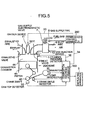
- reference number 20 is the main body of a gas engine, 45 is a piston, 46 is a crankshaft, 44 is a combustion chamber, 41 is an inlet valve, 42 is an exhaust valve, and 43 is an exhaust pipe.
- a gas injection device 10 is provided midway along an inlet pipe 9 for injecting fuel gas into the inlet air flowing in the inlet pipe 9 to be charged into the cylinder through said inlet valve 41.
- Reference number 8 is a gas supply pipe for connecting a fuel gas tank (not shown) accommodating fuel gas and said gas injection device 10.
- Reference number 7 is a gas supply electromagnetic valve provided at the entrance of said gas into said gas injection device 10. The opening of said valve is controlled under the control signal from an electromagnetic valve control device not shown in the drawing to adjust the flow of the gas fuel. The valve is also controlled under the control signal from a combustion control apparatus 200 mentioned later to be shut-off or adjusted of the opening.
- Reference number 11 is an ignition device for torch-igniting the pilot fuel injected into a sub-chamber not shown in the drawing from a pilot fuel injection valve 0011 to promote the combustion of lean fuel gas/air mixture in the main combustion chamber.
- crank angle detector 1 The gas pressure in the combustion chamber, i.e. cylinder pressure is detected with a cylinder pressure detector 1, and crank angle is detected with a crank angle detector 2.
- Reference number 100 is a combustion diagnosis apparatus composed of a noise filter 3, an amplifier 4 for amplifying the cylinder pressure signal passed through the noise filter, and a combustion diagnosis section 5.
- Said noise filter is composed of a low-pass filter for filtering out the noise on the signal inputted from said cylinder pressure detector.
- Said combustion diagnosis section 5 diagnoses the combustion condition in said combustion chamber 44 on the basis of the cylinder pressure signal amplified by said amplifier 4 with the assistance of the crank angle signal from said crank angle detector.
- Reference number 200 is a combustion control apparatus to which is inputted the signal of the result of diagnosis at said combustion diagnosis section 5, and which shuts off or controls the opening of said gas supply electromagnetic valve 7 and also controls the action of said ignition device 11.
- the result of diagnosis by the combustion diagnosis section 5 is displayed on a displaying apparatus 6. It is suitable that an alarm which generates an alarm based on the result of diagnosis is connected to the combustion diagnosis apparatus 100.
- a gas valve (not shown) is unclosed and the fuel in a fuel gas tank (not shown) is supplied to said gas injection device 10, the fuel being adjusted in pressure by a gas pressure adjusting device (not shown).
- the fuel is injected into the air flowing through the gas injection device 10 provided midway along said inlet pipe 9 to be mixed with the flowing air.
- the mixture is introduced into the combustion chamber 44 through the inlet valve 41 and ignited by the flame spouting from said ignition device 11 to be burned in the combustion chamber 44.
- the gas pressure in the combustion chamber 44 detected by said cylinder pressure detector 1 is inputted to the noise filter 3 composed of a super low-pass filter in the combustion diagnosis apparatus 100, high frequency noises are filtered at the noise filter 3, and the cylinder pressure signal smoothed through the filtration is amplified by the amplifier 4 to be inputted to said combustion diagnosis section 5.
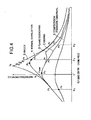
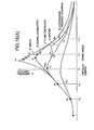
- the cylinder pressure-crank angle curve as shown in FIG.4 is obtained in the combustion diagnosis section 5 from the cylinder pressure inputted from the cylinder pressure detector 1 and the crank angle inputted from the crank angle detector 2.
- Curve A in FIG.4 is a cylinder pressure curve when the combustion is normal.
- the compression pressure P 0 at a predetermined crank angle in the compression stroke shown in FIG.4 is compared in a compression pressure judging means(step) with the predetermined permissible compression pressure P c0 which is the minimum permissible pressure in the compression stroke, and it is judged that the compression pressure P 0 is abnormally low compared to the normal value due to troubles such as gas leakage or mechanical troubles when the pressure P 0 is equal to or lower than the permissible compression pressure P c0 , i.e. when P 0 ⁇ P c0 (E1).
- Curve E in FIG.4 is a cylinder pressure curve when the compression pressure is abnormally low.
- the ratio of the maximum cylinder pressure P p to said compression pressure P 0 at a predetermined crank angle in the compression stroke P p /P 0 is calculated and the calculated maximum pressure ratio P p /P 0 is compared in a maximum cylinder pressure judging means (step) with the predetermined permissible maximum pressure ratio P p0 which is the maximum permissible maximum pressure ratio, and it is judged that the maximum cylinder pressure is abnormally high compared to the design value(normal value) when said calculated maximum pressure ratio P p /P 0 is equal to or exceeds said permissible maximum pressure ratio P p0 , i.e.
- a knock judgung means (step) that knock is occurring in the combustion chamber 44 when the number of cycles S n in which said maximum pressure ratio P p /P 0 is equal to or exceeds the predetermined permissible pressure ratio of knock P h2 , i.e. when P p /P 0 ⁇ P h2 (E5) in a plurality of past cycles before the time point of judgement is equal to or exceeds the permissible number S n0 , i.e. when S n ⁇ S n0 (E6).
- Curve B in FIG.4 is a cylinder pressure curve when knock has occurred.
- the misfire judging means when said maximum pressure ratio P p /P 0 is equal to or smaller than the predetermined minimum permissible pressure ratio P n , i.e. when P p /P 0 ⁇ P n (E7), the combustion pressure ratio P 1 /P 0, which is the ratio of the pressure P 1 at a predetermined crank angle in the combustion stroke to the pressure P 0 at a predetermined crank angle in the compression stroke shown in FIG.4 , is calculated, and when the pressure ratio P 1 /P 0 is equal to or smaller than the predetermined permissible pressure ratio P m of misfire, i.e. when P 1 /P 0 ⁇ P m (E8), misfire is judged to be occurring.
- a predetermined crank angle ⁇ 1 at which pressure P 1 is detected is determined at the position of crank angle symmetrical with regard to the top dead center to the position of a predetermined crank angle ⁇ 0 at which pressure P 0 is detected, as shown in FIG.4 .
- Curve C in FIG.4 is a cylinder pressure curve when misfire has occurred.
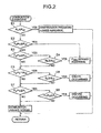
- the second example of combustion diagnosis is the one added to the first example shown in FIG.2 with a process of judging the occurrence of flame quenching.
- the flame quenching judging means(step) of the second example when the maximum cylinder pressure ratio P p /P 0 is equal to or smaller than the minimum permissible pressure ratio P n , i.e. when P p /P 0 ⁇ P n (F7) and at the same time the combustion pressure ratio P 1 /P 0 is equal to or smaller than the predetermined permissible pressure ratio P m of misfire, i.e.
- misfire can be discriminated from flame quenching by calculating combustion pressure ratios P 1 /P 0 and P 2 /P 0 using higher pressure side pressure P 1 and lower pressure side pressure P 2 at two crank angles respectively, and comparing each combustion pressure with the permissible pressure ratio P m of misfire and permissible pressure ratio P m1 of flame quenching respectively.
- the signal of the result of diagnosis is sent to the combustion control apparatus 200.
- the control apparatus 200 shuts off or controls the opening of the gas supply electromagnetic valve 7 and controls the ignition device 11.
- the contents of the result of diagnosis are displayed on the displaying apparatus 6.
- combustion diagnosis of detecting the occurrences of knock, misfire, excessively high maximum cylinder pressure, or flame quenching is performed by a single combustion diagnosis apparatus 100 by carrying out diagnosis using pressure ratios based on the compression pressure at a predetermined crank angle in the compression stroke, so all of necessary combustion diagnoses can be performed with an apparatus of simple construction and low-cost.
- combustion diagnosis is done using pressure ratios based on a compression pressure as described above, absolute values of cylinder pressures is unnecessary and normal diagnosis is maintained without reduction in accuracy even when the output level from the cylinder pressure detector 1 totally decreases due to the deterioration, temperature drift, failed calibration, etc. of the cylinder pressure detector 1. Accordingly, the operation life of combustion diagnosis apparatus can be extended.
- combustion diagnosis with high accuracy is possible by using for combustion diagnosis cylinder pressure signals of which only the filtration of noise is done through a simple low-pass filter. Therefore, complicated processing such as the change of pass-band of the filter is unnecessary as has been with one of the prior arts, and the efficiency of operation of combustion diagnosis is enhanced.
- combustion diagnosis with high accuracy is possible by simple means (steps), as the combustion diagnosis is carried out directly by using only cylinder pressures detected.
- reference number 20 is the main body of a gas engine
- 45 is a piston
- 46 is a crankshaft
- 44 is a combustion chamber
- 41 is an inlet valve
- 42 is an exhaust valve
- 43 is an exhaust pipe.
- a gas injection device 10 is provided midway along an inlet pipe 9 for injecting fuel gas into the inlet air flowing in the inlet pipe 9 to be charged into the cylinder through said inlet valve 41.
- Reference number 8 is a gas supply pipe for connecting a fuel gas tank (not shown) accommodating fuel gas and said gas injection device 10.
- Reference number 7 is a gas supply electromagnetic valve provided at the entrance of said gas into said gas injection device 10. The opening of said valve is controlled under the control signal from an electromagnetic valve control device not shown in the drawing to adjust the flow of the gas fuel. The valve is also controlled under the control signal from a combustion control apparatus 200 mentioned later to be shut-off or adjusted of the opening.
- Reference number 11 is an ignition device for torch-igniting the pilot fuel injected into a sub-chamber not shown in the drawing from a pilot fuel injection valve 0011 to promote the combustion of lean fuel gas/air mixture in the main combustion chamber.
- crank angle detector 1 The gas pressure in the combustion chamber, i.e. cylinder pressure is detected with a cylinder pressure detector 1, and crank angle is detected with a crank angle detector 2.
- Reference number 100 is a combustion diagnosis apparatus.
- the signal of cylinder pressure detected by the cylinder pressure detector 1 and the signal of crank angle detected by the crank angle detector are inputted to the combustion diagnosis apparatus 100, which carries out the diagnosis of the combustion condition in the combustion chamber 44 on the basis of the cylinder pressure signal with the assistance of the crank angle signal.
- Reference number 30 is a generator driven by the gas engine 20
- 36 is a load detector for detecting the load of the gas engine 20 ( load of the generator 30)
- 32 is a cam top detector for detecting the crank angle at which the cam is at top position for a selected cylinder of the gas engine 20 (the cam may be inlet or exhaust cam) .
- the signal of the load of the gas engine from the load detector 32 and the signal of the cam top crank angle from the cam top detector are inputted to the combustion diagnosis apparatus 100.
- Reference number 200 is a combustion control apparatus which controls the fuel injection quantity to be injected from the gas injection device 10 by shutting off or adjusting the openings of the gas supply electromagnetic valve 7 according to a signal 34 of diagnosis result and at the same time controls the injection timing and quantity of the pilot fuel injected from the pilot fuel injection valve 0011 into the ignition device 11 according to a control signal 33, and thus the fuel injection timing and quantity (the fuel injected from the gas injection device and that injected from the pilot fuel injection vale are together referred to as fuel hereafter).
- the result of diagnosis by the combustion diagnosis apparatus 100 is displayed on a displaying apparatus 6. It is suitable that an alarm which generates an alarm based on the result of diagnosis is connected to the combustion diagnosis apparatus 100.
- combustion diagnosis apparatus 100 and combustion control apparatus 200 The working of the combustion diagnosis apparatus 100 and combustion control apparatus 200 will be explained below.
- the gas pressure in the combustion chamber 44 i.e. the pressure signal is inputted to the combustion diagnosis apparatus 100 and the high frequency component is removed by the noise removing filter (not shown in the drawing) to be reduced to an averaged pressure signal without fluctuation in voltage.
- the combustion diagnosis apparatus 100 has been inputted the engine crank angle signal from the crank angle detector 2, the engine load signal from the load detector 36, and cam top signal from the cam top detector 32.
- the cylinder pressure signals of a plurality of cylinders, crank angle signal, cam top crank angle signal, and load signal are inputted continuously to the combustion diagnosis apparatus 100, the combustion is diagnosed in the apparatus 100 based on the input signals, and the result of the diagnosis is inputted moment-to-moment to the combustion control device 200.
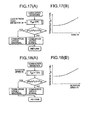
- the combustion control device 200 outputs the fuel ignition time control signal to the engine 20 as shown in FIG.6 or the fuel ignition time control signal and fuel injection quantity control signal to the engine 20 as shown FIG.7 so as the engine to be controlled to be operated in the combustion condition judged to be changed to according to the result of the result of the diagnosis or to be halted as necessary.
- the combustion diagnosis apparatus 100 comprises a single CPU and the combustion control apparatus 200 comprises a double CPU so that, even when the combustion diagnosis apparatus 100 does not work due to run away or so, the control of ignition timing and fuel injection quantity of each cylinder is performed by independent operation of the CPU in the combustion control apparatus 200, while ceasing the function of the combustion diagnosis apparatus 100.
- the detected data of the pressure in the cylinder sent from the cylinder pressure detector 1 is processed in the combustion diagnosis apparatus 100 as follows.
- a standardized cylinder pressure ratio ⁇ P/ ⁇ P 0 where ⁇ P 0 is the difference of the cylinder pressure at a predetermined crank angle in the compression stroke and said reference pressure P b , is calculated, and combustion diagnosis is done using said standardized pressure ratio ⁇ P/ ⁇ P 0 .
- the cylinder pressure signal shown in FIG.8(A) and (B) may be drifted upward or down ward as shown by line Z 1 or Z 2 in the drawings due to the difference in thermal expansion of the component of the pressure detector 1 by the change in the ambient temperature, deterioration with time of the detector 1, etc.
- the combustion diagnosis using said standardized cylinder pressure ratio makes it possible to diagnose maintaining desired accuracy without decreasing the accuracy even when the output level of the cylinder pressure detector decreases totally due to the deterioration of the pressure detector, temperature drift, calibration failure, and so on, or the level increases totally due to other reasons.
- FIG.16 (A) The data of cylinder pressure-crank angle diagram as shown in FIG.16 (A) is inputted in the combustion diagnosis apparatus 100 from the cylinder pressure detector 1 and crank angle detector 2.
- Curve A in FIG.16(A) is a cylinder pressure curve when the combustion in the cylinder is normal.
- whether the sensor is abnormal or not (S01) is determined according to the flowchart of FIG.34 in which whether the sensor is normal or abnormal is judged. If the sensor is abnormal, an action of changing the detector or other appropriate action must be taken. If the sensor is normal, the flow proceeds to cylinder pressure diagnosis steps.
- Curve E in FIG. 16 (A) is a cylinder pressure diagram when compression pressure P 0 is abnormally low.
- standardized maximum pressure ratio ⁇ P p / ⁇ P 0 is compared with the maximum permissible pressure ratio P p0 , and when ⁇ P p / ⁇ P 0 ⁇ P p0 (S2), or when the number N h of cycles operated under the condition of ⁇ P p / ⁇ P 0 ⁇ P h1 , where P h1 is a predetermined pressure ratio lower than a predetermined pressure ratio P p0 , is equal to or exceeds the permissible number No , that is, when N h ⁇ No (S4), the maximum pressure is judged to be abnormally high.
- the knock judging means it is judged that knock is occurring in the combustion chamber 44 when the number of cycles S n in which said standardized maximum pressure ratio ⁇ P p / ⁇ P 0 is equal to or exceeds the predetermined permissible pressure ratio of knock P h2 , i.e. when ⁇ P p / ⁇ P 0 ⁇ P h2 (S5) in a plurality of past cycles before the time point of judgement is equal to or exceeds the permissible number S n0 , i.e. when S n ⁇ S n0 (S6).
- Curve B in FIG.16(A) is a cylinder pressure curve when knock has occurred.
- misfire judging means(step) when said standardized maximum pressure ratio ⁇ P p / ⁇ P 0 is equal to or smaller than the predetermined minimum permissible pressure ratio P n , i.e. when ⁇ P p / ⁇ P 0 ⁇ P n (S7), a standardized combustion pressure ratio ⁇ P 1 / ⁇ P 0 , which is the ratio of the pressure difference ⁇ P 1 at a predetermined crank angle in the combustion stroke to the pressure difference ⁇ P 0 at a predetermined crank angle in the compression stroke shown in FIG.16(A) , is calculated, and when the pressure ratio ⁇ P 1 / ⁇ P 0 is equal to or smaller than permissible pressure ratio P m of misfire, i.e.
- the predetermined crank angle ⁇ 1 at which pressure P 1 is detected is determined at the position of crank angle symmetrical with regard to the top dead center to the position of the predetermined crank angle ⁇ 0 at which pressure P 0 is detected, as shown in FIG.16(A) .
- the predetermined crank angle ⁇ 2 at which pressure P 2 is detected is determined at the position of crank'angle symmetrical with regard to the top dead center to the position of the predetermined crank angle ⁇ b at which reference pressure P b is detected, as shown in FIG.16(A) .
- Curve C in FIG.16(A) is a cylinder pressure curve when misfire has occurred.
- the flame quenching judging means when the standardized maximum pressure ratio ⁇ P p / ⁇ P 0 is equal to or smaller than the minimum permissible pressure ratio P n , i.e. when P p /P 0 ⁇ P n (S7) and at the same time the standardized combustion pressure ratio ⁇ P 1 / ⁇ P 0 is equal to or smaller than the predetermined permissible pressure ratio P m of misfire, i.e. when ⁇ P 1 / ⁇ P 0 ⁇ P m (S8) and further the lower pressure side standardized combustion pressure ratio ⁇ P 2 / ⁇ P 0 is equal to or larger than the permissible pressure ratio P m1 of flame quenching, i.e. when ⁇ P 2 / ⁇ P 0 ⁇ P m1 (S9), flame quenching is judged to be occurring.
- Curve D in FIG.16(A) is a cylinder pressure curve when flame quenching has occurred.
- misfire can be discriminated from flame quenching by calculating standardized combustion pressure ratios ⁇ P 1 / ⁇ P 0 and ⁇ P 2 / ⁇ P 0 using higher pressure side pressure P 1 and lower pressure side pressure P 2 at two crank angles respectively, and comparing each combustion pressure with the permissible pressure ratio P m of misfire and permissible pressure ratio P m1 of flame quenching respectively.
- the threshold value P p0 , P h1 for the maximum pressure, threshold value P h2 for knock, threshold value P n for misfire and flame quenching are such that P n ⁇ P s1 P sh ⁇ P h2 ⁇ P h1 ⁇ P p0 .
- Each of these threshold values may be changed as a function of engine load or engine rotation speed or engine operating conditions including inlet air temperature.
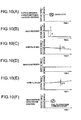
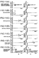
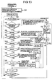
- the combustion control apparatus 200 causes the activation of the engine stopper to shut down the engine 20 ( FIG.10(A) , FIG.11(A) , step D1 and D2 of FIG.12 ⁇ FIG.13 ).
- the combustion control apparatus 200 allows the fuel injection timing to be retarded by a certain crank angle ⁇ ( FIG.10(B) , FIG.11(B) , step D5 and D11 off FIG.12 ⁇ 13 ).
- the occurrence or continuation of knock can be prevented positively without delay and fluctuations in combustion condition is suppressed.
- the engine can be controlled to operate in the high performance range just before knock occurs.
- the combustion control apparatus 200 allows the fuel supply to the concerned cylinder to be shut off or retard the ignition timing to be retarded to that with which the engine can be operated safely ( FIG.10(F) , FIG.11(G) , step D4 and D10 of F IG.12 ⁇ FIG.13 ).
- the combustion control apparatus 200 allows the fuel ignition timing to be retarded with a rate of a certain crank angle ( ⁇ T h ) per unit time ( FIG.10(C) , FIG.11(C) , step D6 and D12 of FIG.12 - FIG.13 ).
- the combustion control apparatus allows the fuel injection timing to be advanced with a rate of a certain crank angle ( ⁇ T1) per unit time ( FIG.10 (E) , FIG.11 (E) , step D7 and D13 of FIG.12 ⁇ FIG.13 ).
- the maximum pressure is always maintained in the range of the reference maximum pressure, the engine performance is maintained at desired one, and at the same time the increase of generation of NOx due to excess elevation of combustion temperature is suppressed.
- the combustion control apparatus 200 allows to shut off the fuel injection of the concerned cylinder in which misfiring is occurring ( FIG.10 (F) , FIG.11 (G) , step D3 and D10 of FIG.12 - FIG.13 ).
- the combustion control apparatus 200 allows the fuel injection to the concerned cylinder in which flame quenching has occurred to be increased ( FIG.11(F) , step D04 and D011 of FIG.13 ).
- combustion diagnosis by the combustion diagnosis apparatus 100 and control of combustion by the combustion control apparatus 200 in response to the result of the diagnosis can always be done during the operation of the engine.
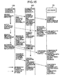
- FIG.14A ) ⁇ FIG.14 (D) are shown the changes of the fuel injection timing and fuel injection quantity with time when the combustion is controlled by the combustion control apparatus 200 on the basis of the result of the diagnosis by the combustion diagnosis apparatus 100.
- FIG.15 shows the working state of the combustion diagnosis apparatus 100, combustion control apparatus 200 and gas engine 20.
- a diagnosis result is outputted from the combustion diagnosis apparatus 100 showing abnormality of a cylinder pressure sensor 1
- this sensor is stopped to diagnose the combustion by the combustion control apparatus 200, and the apparatus 200 allows the ignition timing to be retarded by a certain crank angle to bring it to a safety range while leaving the abnormal state of the cylinder pressure sensor as it is.
- the combustion diagnosis apparatus 100 and combustion control apparatus 200 restore normal operation and the ignition timing of the concerned cylinder is recovered to the normal timing.
- Permissible maximum pressure ratios P p0 are determined as' a function of engine operating conditions including inlet air temperature, and the combustion is judged similarly as mentioned above.
- the maximum value P sh and minimum value P s1 for reference maximum pressure ratio, permissible compression pressure difference P c0 , permissible pressure ratio for knock P h2 , permissible minimum pressure ratio for misfire P n , permissible pressure ratio for misfire P m , and permissible pressure ratio for flame quenching P m1 , etc. may be determined as a function of engine load W, engine rotation speed N, and engine operating conditions including inlet air temperature respectively.
- threshold values such as permissible maximumpressure ratios P p0 (threshold values), the maximum value P sh and minimum value P s1 for reference maximum pressure ratio, permissible compression pressure difference P c0 , permissible pressure ratio for knock P h2 , permissible minimum pressure ratio for misfire P n , permissible pressure ratio for misfire P m , and permissible pressure ratio for flame quenching P m1 are not constant in diagnosing the combustion but they are changed according to changes in engine operating conditions and the combustion is controlled per cylinder.
- reference numeral 100a is an ON-OFF switch for allowing-or-not the actuation of the combustion diagnosis apparatus.
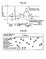
- FIG.24 the judging of abnormality of cylinder pressure sensor 1 will be explained with reference to FIG.24 , FIG.33(A) , FIG.33(B) , and FIG.34 .
- P b is the reference pressure at or before the beginning of compression
- P 3 is the pressure at a crank angle advanced by a certain crank angle from that of P 0 (i.e. P3 is measured earlier in time than P 0 )
- P 1 is the pressure at a crank angle in retard of a certain crank angle from that of P 0 (i.e. P 1 is measured later in time than P 0 )
- P 2 is the pressure at a crank angle in retard of a certain crank angle from that of P 1 .
- the crank angle range between RWA and RWB is the abnormality judging range
- the cylinder pressure range between PTb and PTa is the pressure detecting range including the high pressure for detecting knock
- PSb is the maximum permissible inlet air pressure
- Psa is theminimumpermissible inlet airpressure.
- the range between Aa and Ab is the range of combustion in which the maximum cylinder pressure P p occurs.
- the detected cylinder pressure includes almost no noise as shown in FIG.33 (A) . If the detected pressure includes noise as shown in FIG.33 (B) , the presence or absence of abnormality of the sensor is judged by calculating the standard deviation of Pb as shown in FIG.34 .
- the sensor is judgedtobe normal. If the standard deviation is not smaller than the permissible standard deviation ⁇ , the pressure detector (sensor) 1 is judged to be abnormal (E8) when the states which do not suffice any one of the conditions (a) - (d) described above continues to occur for predetermined i times (E6), since the case may occur in which the pressure exceeds instantaneously said range of PTa - PTb owing to trigger pulses due to noise.
- k is set to 1 and again the diagnosis of all cylinders is performed.
- step (a) as the sensor 1 is judged to be abnormal by step (a) when there occurs a plurality of the cases in which the detected pressure signal exceed the pressure range of PTb - PTa, the occurrence of spark noise, a break in wire, poor electric contact, etc. can be detected with high accuracy even when there occurs instantaneous overshoot in pressure beyond said pressure range due to trigger pulses, etc.
- step (b) The occurrence of drift due to the change with time is detected by step (b). Further, whether the pressure is detected or not with correct relation between the pressure and crank angle is confirmed by step (c).
- abnormalities in the cylinder pressure detector 1 and crank angle detection are detected from many faces automatically, runaway of diagnosis can be prevented without fail when the cylinder pressure detector 1 is abnormal.
- the engine can be operated by controlling only by the combustion control apparatus 200 with diagnosing suspended or the engine can be halted to repair the detector 1 as shown in FIG.6 , 7 , 20 .
- the combustion controller actuates to retard the ignition timing to a safety range to preserve the abnormality thereof as it is.
- the combustion diagnosis apparatus diagnoses normally after the sensor is replaced, but in this state the apparatus judges misfire.
- the combustion in the cylinder begins with the ignition timing set to a value in the safety range.
- Combustion control of the cylinder is restarted by manually resetting the sensor of the concerned cylinder, and the combustion recovers to a normal state from a state of rather weak combustion.
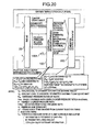
- FIG. 20 is a total block diagram of the combustion diagnosis system of gas engine of the embodiment according to the present invention in the case stepless control is done only in normal range and corresponds to FIG.7 .
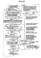
- FIG.21 is a total control flowchart of the combustion diagnosis system of gas engine of the embodiment according to the present invention and corresponds to FIG.9 except that stepless control is done only in normal range.
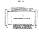
- FIG.22 is an illustration explaining the method of transmission of combustion diagnosis signals in analog form applied to the invention of FIG.20 and FIG.21 .
- FIG.23 (A) is a graph showing totally the change of the value of analog-form signal for each of the categories of the result of combustion diagnosis
- FIG.23(B) is a graph a part of FIG.23(a) partially enlarged.
- FIG.24 is a pressure curve for explaining the detection of cylinder pressure for combustion diagnosis.
- threshold values are provided for detected pressure in the combustion range of crank angle of the range Aa ⁇ Ab shown in FIG.24 so that stepwise representation of analogue value is possible in a serial data transmission wire.
- Each level of threshold values P p0 and P h1 for detecting the abnormal Pmax, P h2 for detecting knock, P n for detecting misfire and flame quenching, etc. are determined to be P p0 ⁇ P h1 ⁇ P h2 ⁇ P sh ⁇ P s1 ⁇ P n , the level decreasing stepwise.
- step S'01 if the sensor is judged to be normal in step S'01, then compression pressure difference ⁇ P 0 is abnormally low or not is judged (S'1).
- Said reference pressure difference ⁇ P 0 detected in the compression stroke range is compared with the permissible pressure difference P c0 (threshold value) for ⁇ P 0 , and when ⁇ P 0 ⁇ P c0 , the compression pressure Pc is judged to be abnormally low due to mechanical trouble such as gas leakage (S'1).
- step S'2 When the condition of step S'2 holds or the number N h of operated cycles in S' 3 is equal to or exceeds the permissible number N h0 (S' 4), the maximum cylinder pressure P p is judged to be abnormally elevated over the design value (normal value) .
- Knock judging step S' 5 ⁇ S' 6, and misfire and flame quenching judging step S'7 ⁇ S'9 are the same as FIG.9 .
- combustion diagnosis is performed by comparing standardized cylinder pressure ratio ⁇ P/ ⁇ P 0 in said combustion range with threshold values determined for every diagnosis category information, each level of said threshold values being decreased stepwise so that the information of different category can be judged based on the corresponding level of threshold value, detection range being set to be in the crank angle near the maximum pressure, said threshold values being P p0 and P h1 for detecting abnormal Pmax, P h2 for detecting knock, P n for detecting misfire and flame quenching, etc., the level of each threshold value being decreased in orderly sequence of P p0 ⁇ P h1 ⁇ P h2 ⁇ P sh ⁇ P s1 ⁇ P n .
- FIG.20 is a block diagram showing total configuration of the embodiment of a gas engine combustion diagnosis system, in which diagnosis is done by determining threshold values shown in FIG.23 (A) and FIG.23 (B) for the maximum pressure P p detected in the range of crank angle Aa - Ab corresponding to combustion range.
- reference numeral 20 is the multi-cylinder engine
- 100 is the combustion diagnosis apparatus which diagnoses the combustion by detected cam top crank angle and cylinder pressure-crank angle data through following the flow shown in FIG.21 .
- Cp the analog level for transmitting abnormal Pmax judgement
- Ce analog level for compression pressure judgement
- Ck analog level for knock judgement
- Cq analog level for flame judgement quenching
- Cm analog level for misfire judgement
- Cx analog level for abnormal sensor judgement, each analog level being determined to decrease stepwise in the orderly sequence of Cp > Ce > Ck > Cq > Cm > Cx.
- the signal of the result of diagnosis transmitted from the combustion diagnosis apparatus 100 to the combustion control apparatus 200 is composed of analog levels, each analog level being determined for each diagnosis category. Therefore, the combustion control apparatus 200 is able to judge each information of different category in each pertinent analog level.
- the analog level for transmitting the information of diagnosis category of normal combustion state is positioned in the center part of the levels, the level for transmitting the information of abnormal maximum cylinder pressure or compression pressure which generally related to engine conditions as a whole is set to a value in higher level range, and the levels for transmitting the information of misfire, flame quenching, abnormal sensor, and break in wire, that are generally experienced in an individual cylinder are set to a value in lower level range.
- the pressure or pressure ratio converted in stepless analog level signal corresponding with the pressure or pressure ratio can be transmitted to the combustion control apparatus 200.
- the combustion diagnosis/control apparatus of an internal combustion engine the number of analog signal transmission wire corresponding with the number of cylinders is connected between the combustion diagnosis apparatus 100 and combustion control apparatus 200, and the diagnosed result of each diagnosis category is transmitted in serial order on each of analog signals which are set in stepwise decreasing sequence.
- the combustion control apparatus judges the diagnosis category or can determine the combustion pressure or pressure ratio corresponding with the analog signal.
- the analog information of K category of diagnosis result can be transmitted on one analog signal transmission wire 101 per cylinder, which means that m wires suffice for m cylinders.
- one of signal transmission wires 101 corresponds to the information of one of cylinders, only the combustion in the cylinder of which the wire is broken becomes uncontrollable and the combustion in other cylinders are not influenced. Furthermore, as the information is of analog, malfunctions do not occur due to noises in the signals.
- P ⁇ P p / ⁇ P 0
- analog information thereof is calculated by the following equation;
- C Cq - Ck ⁇ P n - P h ⁇ 2 / P n - P h ⁇ 2 + Ck .
- the combustion control apparatus 200 receives stepless pressure level information in the normal combustion range.
- the combustion control apparatus 200 always controls the combustion condition according to the result of moment-to-moment diagnosis obtained by the combustion diagnosis apparatus through changing the fuel ignition timing of pilot fuel or gas fuel, or fuel injection quantity.
- the display connected to the combustion diagnosis apparatus of the present invention can display two kinds of data, combustion diagnosis data and pressure waves.
- FIG.25 shows an example of displayed combustion diagnosis result.
- cylinder numbers #1 ⁇ #18 are arranged in columns, diagnosis categories are arranged in rows, and the result of each diagnosis category for each cylinder transmitted from the combustion diagnosis apparatus is displayed by pertinent mark such as abnormal sensor(X), abnormal maximum pressure Pp (E), knock(K), high maximum pressure P p (H), adequate maximum pressure P p (N), low maximum pressure P p (L), flame quenching (Q), misfire (M), and reduced compression pressure (C).
- abnormal sensor(X) abnormal maximum pressure Pp (E), knock(K), high maximum pressure P p (H), adequate maximum pressure P p (N), low maximum pressure P p (L), flame quenching (Q), misfire (M), and reduced compression pressure (C).
- Each mark of the diagnosis category is shown in blank letter in a black rectangle so as to be easily recognized, as the number of cylinders is large in this case.
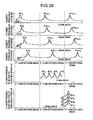
- FIG.26 shows the representation of the cylinder pressure waves of each cylinder of a 4-cylinder engine in the display and the process of transmitting the pressure waves from the combustion diagnosis apparatus to the display, as an example of a multi-cylinder engine.
- the pressure wave-forms in the top to 4 th stage in the drawing are the detected cylinder pressure wave-forms of the four cylinders in which the pressure waves are shown for every cycle, the crank angle of cam top (of the inlet cam) being indicated as 0°, the pressures being measured at equal interval of crank angle.
- the pressure waves of four cylinders are shown in the display 124 as shown in the last but one stage.
- the data is transmitted from the combustion diagnosis apparatus 100 to the displaying apparatus 6 in serial order, as there is no relation between displaying and controlling of combustion.
- each pressure-crank angle curve of four cylinders is written to the first ring memory of the combustion diagnosis side every time the pressure is detected by the cylinder pressure detector(sensor).
- These pressure-crank angle curves are transmitted on the signal transmission wire 101 to the displaying apparatus 6 in such a way that the pressure of each cylinder is retarded in phase from that of the cylinder of next cylinder number by crank angle ⁇ a1 ⁇ , ⁇ a2 ⁇ , ⁇ a3 ⁇ , ⁇ a4 ⁇ respectively. They are transmitted in serial order in the crank angle range of 720° of one cycle, thus the small number of transmission wire 101 is effectively utilized. If the transmission range is set to 60 - 80 crank angle for example, the pressure waves are possible to be sent on the signal transmission wire 101 in serial order within 720 of one cycle.
- the representation in the last stage in the drawing shows the cylinder pressure curves displayed on the oscillogragh 124 of the displaying apparatus 6. As shown in the representation, each of the curves is shown on the oscillogragh 124 of the displaying apparatus 6 at a spacing of pressure value ⁇ for easy recognition of all of the pressure curves, as the cylinder pressure curves are very similar to each other.
- the curves sent from the combustion diagnosis side by retarding in phase by crank angles of ⁇ a1 ⁇ , ⁇ a2 ⁇ , ⁇ a3 ⁇ , ⁇ a4 ⁇ respectively are advanced by the same crank angles respectively and displayed with reference to the cam top crank angle of reference cam (for example, the inlet cam of #1 cylinder) with a spacing of pressure value ⁇ .
- FIG.27 shows an example of data configuration on the combustion diagnosis apparatus side and displaying apparatus side to perform said displaying.
- a ring buffer memory 110 (rbuf1) of the combustion diagnosis apparatus side has a memory part for memorizing the cam top crank angle of the reference cam and ring memory parts for memorizing the pressure curves of #1 ⁇ #4 cylinders during at least 720 of one cycle or above, concretively, during several cycles.
- a write-in pointer 113 determines the position for writing the detected data from the cylinder pressure detector 1 and crank angle detector 2.
- Reference numeral 112 is a memory for memorizing the relative angle information that are crank angles ⁇ a1 ⁇ a4 ⁇ from the cam top crank angle of the reference cam to the start crank angle of each pressure curve.
- Reference numeral 111 is a readout pointer for reading from the ring memory parts each pressure curve with the timing determined based on said memorized angle information of ⁇ a1 ⁇ a4 ⁇ in order to read out the data with crank angle phase retarded by angle ⁇ a1 ⁇ , ⁇ a2 ⁇ , ⁇ a3 ⁇ , ⁇ a4 ⁇ respectively.
- a ring buffer memory 120 (rbuf2) of the displaying apparatus side has four ring memory parts for memorizing pressure curves, in which the pressure data of #1 ⁇ #4 cylinders sent from the combustion diagnosis 100 side with crank angle phase retarded by angle ⁇ a1 ⁇ , ⁇ a2 ⁇ , ⁇ a3 ⁇ , ⁇ a4 ⁇ respectively are memorized in a certain area (wlen) in sequence with crank angle phase advanced this time by angle ⁇ a1 ⁇ , ⁇ a2 ⁇ , ⁇ a3 ⁇ , ⁇ a4 ⁇ respectively.
- Reference numeral 121 is a write-in pointer for determining write-in timing to write in the pressure data transmitted on the serial signal transmission wire 101 with crank angle phase advanced by angle ⁇ a1 ⁇ , ⁇ a2 ⁇ , ⁇ a3 ⁇ , ⁇ a4 ⁇ respectively to the ring memory parts corresponding to #1 ⁇ #4 cylinders.
- Reference numeral 122 is a readout pointer for determining the timing to read out the data from the ring memory parts corresponding to #1 ⁇ #4 cylinders, giving pressure spacing value ⁇ between each pressure data.
- FIG.28 ⁇ FIG.31 are flowcharts for processing the pressure data for displaying.
- FIG. 28 is a crank angle interrupt handling flowchart on the combustion diagnosis apparatus side(data sending-out side)
- FIG.29 is a main processing flowchart on the combustion diagnosis side(data sending-out side)
- FIG.30 is a data reception interrupt handling flowchart on the displaying apparatus side(data receiving side)
- FIG.31 is a a crank angle interrupt handling flowchart on the displaying apparatus side(data receiving side).
- Similar operation is effected in the succeeding cycles until the write-in pointer runs over the size of the ring buffer memory rbuf1.
- the write-in pointer 113 overrun the size of the ring buffer memory rbuf1 (S23)
- the write-in pointer is initialized to 0 (S24) to overwrite from the initial part of the ring memory.
- FIG.29 is a main processing flowchart of the combustion diagnosis apparatus side(data sending-out side).
- the write-in pointer and readout pointer is set to 0 (S30), after the cam top crank angle of the reference cam is detected(S32), if memory area for more than 1 cycle of crank angle (720°) is remaining in the write-in memory area of the ring buffer rbuf1 (33), k is set to 1 for #1 cylinder(34), crank angle a1 is read out from the timing memory, and the pressure data of #1 cylinder in the crank angle range corresponding to the diagnosis range is transmitted on the signal transmission wire 101 to the displaying apparatus 6.
- crank angle a2, a3, a4, ... is read out every time k is increased by 1 to transmit successively the pressure data of each cylinder to the displaying apparatus with the crank angle phase thereof retarded by the value of said corresponding crank angle (S36).
- next write-in area iptr is set to iptr++ (S39), if the write-in area is equal to or larger than rdptr+ wlen (area corresponding to the diagnosis range) (S40), similar operation is repeated to write the data successively into the still-unwritten area in the ring buffer rbuf1.
- write-in area itpr is smaller than rdptr+ wlen (area corresponding to the diagnosis range)
- iptr is set to rdptr++ to proceed to overwriting to the ring buffer rbuf1 (s41).
- the pressure-crank angle data of each cylinder and cam top crank angle of the reference cam detected by the cylinder pressure detector 1 and crank angle detector 2 are memorized to the ring buffer rbuf1 in the combustion diagnosis apparatus 100.
- data interrupt is started every time data is received from the signal transmission wire 101 (S50A), write-in pointer is set to iptr(S50) to write each data of #1 ⁇ #4 cylinders to the corresponding ring memory part of the ring buffer rbuf2(S50).
- the write-in pointer 122 is again set to iptr to effect the writing-in of the next cycle(S54).
- the readout pointer is matched with the cam top crank angle (S62), and the data of #1 ⁇ #4 cylinders are read out from the corresponding ring memory part in the ring buffer rbuf2(S63).
- each data being the pressure-crank angle curve in a certain crank angle range wlen from the pressure wave data beginning point which is at a crank angle of relative crank angle informational, a2, ⁇ respectively from the cam top crank angle of the reference cam, are received, for example when the cam top crank angle for the next cycle is detected, the pressure curves are displayed on the oscilloscope 124 of the displaying apparatus with the pressure curve of each cylinder spaced by a pressure value ⁇ .
- the readout pointer is advanced by wlen to be returned to S61 to readout the data of the next cycle.
- the combustion diagnosis can be done which detects the occurrence of knock, misfire, excessive elevation of the maximum cylinder pressure, and flame quenching, with a combustion diagnosis system by diagnosing combustion using the pressure ratio based on the detected cylinder pressure. Therefore, all categories necessary for combustion diagnosis of an internal combustion engine can be performed by an apparatus of simple constitution and low cost.
- the combustion diagnosis is effected by using the pressure ratio based on the cylinder pressure as mentioned above, the absolute value of the cylinder pressure is not required. So, even when the output level from the cylinder pressure detector totally decreases, normal combustion diagnosing function can be maintained without reduction in accuracy. Accordingly, life expectancy of usage of the combustion diagnosis system can be extended.
- combustion diagnosis can be performed directly by using only the detected cylinder pressure, so highly accurate combustion diagnosis is possible with simple means (step) .
- the present invention by stopping the engine by allowing the combustion control apparatus to activate the engine operation stopper when a diagnosis result has been outputted from the combustion diagnosis apparatus that the standardized maximum pressure ratio ⁇ P p / ⁇ P 0 is equal to or exceeds the predetermined permissible maximum pressure ratio P p0 , the detection of excessively high maximum cylinder pressure and the action to deal with that can be taken exactly without delay. Therefore, engine breakage or reduction of engine durability due to the excessive high cylinder pressure can be prevented with reliability.
- the fuel ignition timing is retarded by a certain crank angle by the combustion control apparatus.
- the fuel ignition timing is advanced by a certain crank angle by the combustion control apparatus. Therefore, the cylinder pressure is maintained below the maximum reference pressure and the expected engine performance is maintained resulting in suppression of increased generation of NOx due to excessively high combustion temperature.
- the knock when a diagnosis result has been outputted from the combustion diagnosis apparatus that knock has occurred by comparing the standardized maximum pressure ratio ⁇ P p / ⁇ P 0 with knock threshold, the knock is prevented without delay and with reliability by retarding the fuel ignition timing by a certain crank angle through the combustion control apparatus, and the engine can always be operated in the high performance range just before knock occurs.
- the fuel injection to the concerned cylinder in which misfire has occurred is cut off.
- the occurrence of misfire is detected with reliability without delay and measures can be taken to deal with the situation, that is, to stop the fuel injection to the concerned cylinder, through which the operation of the other cylinders can be continued without influenced by the concerned cylinder.
- the occurrence of flame quenching is detected with reliability without delay and measures can be taken to deal with the situation, that is, to increase the quantity of fuel injection to the concerned cylinder, through which the continuation of misfire is prevented and the operation of the other cylinders can be continued without influenced by the concerned cylinder.
- each of threshold values for combustion diagnosis such as permissible maximum cylinder pressure, permissible minimum compression pressure, permissible pressure of knock, misfire, flame quenching can be determined as a function of engine operating conditions such as engine load, engine rotation speed, inlet air temperature. Therefore, the threshold values can be adjusted according to engine operating conditions so that the engine is operated always near knocking limit, resulting in highly accurate combustion diagnosis.
- the combustion diagnosis apparatus when a diagnosis result has been outputted from the combustion diagnosis apparatus that a cylinder pressure detector is abnormal, the fuel injection timing of the concerned cylinder of which the pressure detector is abnormal is retarded by a certain crank angle to a safety range. After the pressure detector is recovered, the combustion diagnosis apparatus recovers automatically normal operation and allows the combustion control apparatus to operate normally to recover the normal injection timing of the concerned cylinder.
- the pressure detector of the concerned cylinder is repaired or recovered while the injection timing of the concerned cylinder is adjusted to a safe timing for combustion, and after the recovery of the pressure detector, the normal combustion control is recovered, so the abnormal pressure detector can be dealt with without halting the operation of the engine.
- the occurrence of spark noise, a break in wire, poor electric contact, etc. can be detected by detecting the pressure signal overshooting or undershooting the ordinary maximum or minimum value of cylinder pressure, the occurrence of drift due to the change over time of the pressure detector can be detected, and whether the pressure is detected without deviation in relation to crank angle or not can be confirmed.
- the abnormality of cylinder pressure detector can be detected automatically from various facets, and fast recovery of the pressure detector from abnormal state is possible resulting in smooth combustion diagnosis.
- the drift due to the change in the temperature of the pressure sensor and change over time of the pressure sensor does not influence the result of diagnosis, and abnormalities such as abnormal combustion, failure in the cylinder pressure sensor, and a break in wire can be detected.
- the detection of knocking state which has been difficult can be grasped indirectly by the ratio of pressure differences as a measure, and engine operation near knock limit is always possible, resulting in increased engine efficiency.
- the apparatus can be recovered without stopping the engine, since in such a case the fuel ignition timing is retarded to a position safe for combustion through the combustion control apparatus.
- the number of signal transmission wires between the combustion diagnosis apparatus and combustion control apparatus is reduced compared with the conventional method of connection, and if a break in wire occurs, the influence thereof is limited only to the concerned cylinder; besides, the broken wire is able to be identified because the analog value on the wire becomes zero level which belongs to no category of diagnosis. On the contrary, with conventional digital signal transmission wires, the identification of broken wire is impossible.
- the failed sensor when any of the cylinder pressure sensors fails during engine operation, the failed sensor can be replaced without stopping the engine operation.
- stepless control to effect feedback of the deviation in pressure from the target value of cylinder pressure, and more carefully thought out control is possible, resulting in further increased engine efficiency.
- the present invention is applicable not only to the gas engine ignited by torch ignition of pilot fuel explained in the embodiments but also to all types of reciprocating internal combustion engine such as other type of gas engines and diesel engines.
Applications Claiming Priority (2)
| Application Number | Priority Date | Filing Date | Title |
|---|---|---|---|
| JP2001098635 | 2001-03-30 | ||
| EP02708733A EP1375890A4 (fr) | 2001-03-30 | 2002-03-29 | Procede et dispositif de diagnostic et de controle de la combustion d'un moteur a combustion interne |
Related Parent Applications (2)
| Application Number | Title | Priority Date | Filing Date |
|---|---|---|---|
| EP02708733.7 Division | 2002-03-29 | ||
| EP02708733A Division EP1375890A4 (fr) | 2001-03-30 | 2002-03-29 | Procede et dispositif de diagnostic et de controle de la combustion d'un moteur a combustion interne |
Publications (2)
| Publication Number | Publication Date |
|---|---|
| EP2479412A2 true EP2479412A2 (fr) | 2012-07-25 |
| EP2479412A3 EP2479412A3 (fr) | 2014-08-13 |
Family
ID=29717417
Family Applications (2)
| Application Number | Title | Priority Date | Filing Date |
|---|---|---|---|
| EP02708733A Withdrawn EP1375890A4 (fr) | 2001-03-30 | 2002-03-29 | Procede et dispositif de diagnostic et de controle de la combustion d'un moteur a combustion interne |
| EP12164738.2A Withdrawn EP2479412A3 (fr) | 2001-03-30 | 2002-03-29 | Appareil et procédé de contrôle/diagnostic de la combustion d'un moteur à combustion interne |
Family Applications Before (1)
| Application Number | Title | Priority Date | Filing Date |
|---|---|---|---|
| EP02708733A Withdrawn EP1375890A4 (fr) | 2001-03-30 | 2002-03-29 | Procede et dispositif de diagnostic et de controle de la combustion d'un moteur a combustion interne |
Country Status (7)
| Country | Link |
|---|---|
| US (1) | US6810320B2 (fr) |
| EP (2) | EP1375890A4 (fr) |
| JP (1) | JP4138491B2 (fr) |
| KR (1) | KR20030036206A (fr) |
| CN (2) | CN1308586C (fr) |
| CA (1) | CA2411976A1 (fr) |
| WO (1) | WO2002079629A1 (fr) |
Families Citing this family (103)
| Publication number | Priority date | Publication date | Assignee | Title |
|---|---|---|---|---|
| JP3912500B2 (ja) * | 2002-03-29 | 2007-05-09 | 三菱自動車工業株式会社 | 内燃機関 |
| JP4155807B2 (ja) * | 2002-12-03 | 2008-09-24 | 富士通テン株式会社 | ノッキング検出装置 |
| JP4096835B2 (ja) | 2003-08-06 | 2008-06-04 | トヨタ自動車株式会社 | 内燃機関の制御装置および内燃機関の失火判定方法 |
| US7000596B2 (en) * | 2003-10-03 | 2006-02-21 | Cummins Westport Inc. | Method and apparatus for controlling an internal combustion engine using combustion chamber pressure sensing |
| US7055506B2 (en) * | 2004-02-03 | 2006-06-06 | Cssm Holdings Pty Ltd | Fuel control system for a dual fuel internal combustion engine |
| US7363883B2 (en) * | 2004-03-19 | 2008-04-29 | Mitsubishi Heavy Industries, Ltd. | Gas engine electric power generating system effectively utilizing greenhouse gas emission credit |
| GB0410135D0 (en) * | 2004-05-06 | 2004-06-09 | Ricardo Uk Ltd | Cylinder pressure sensor |
| JP4354334B2 (ja) * | 2004-05-20 | 2009-10-28 | 本田技研工業株式会社 | 筒内圧センサの故障を判定する装置 |
| JP4333536B2 (ja) * | 2004-09-14 | 2009-09-16 | 株式会社デンソー | ディーゼルエンジン制御システム |
| CA2525020C (fr) * | 2004-11-09 | 2011-12-20 | Honda Motor Co., Ltd. | Capteur d'etat de combustion pour moteur |
| FR2879665B1 (fr) * | 2004-12-17 | 2009-12-18 | Inst Francais Du Petrole | Methode de detection de combustion anormale pour moteurs a combustion interne |
| EP1696218B9 (fr) * | 2005-02-25 | 2010-09-15 | STMicroelectronics Srl | Application à la détection du cliquetis dans un moteur à combustion interne, identification du cliquetis et système de contrôle et méthode correspondante de traitement de signal. |
| KR100679567B1 (ko) * | 2005-03-03 | 2007-02-06 | 홍경순 | 고기구이판 및 그 제조방법 |
| EP2275946A1 (fr) * | 2005-03-04 | 2011-01-19 | STMicroelectronics S.r.l. | Réseau neural probabilistique et procède d'apprentissage associé |
| US7251990B2 (en) | 2005-03-04 | 2007-08-07 | Stmicroelectronics S.R.L. | Method and a relative device for diagnosing misfire or partial combustion conditions in an internal combustion engine |
| US8484968B2 (en) * | 2005-03-31 | 2013-07-16 | General Electric Company | System and method for operating a compression-ignition engine |
| DE102005030535A1 (de) * | 2005-06-30 | 2007-01-04 | Robert Bosch Gmbh | Verfahren zur Diagnose von Sensoren |
| FR2906315B1 (fr) * | 2006-09-22 | 2008-12-26 | Dalkia France Soc En Commandit | Dispositif de protection pour un moteur a gaz. |
| DE102007027709A1 (de) * | 2006-12-27 | 2008-07-03 | Robert Bosch Gmbh | Verfahren zum Start einer Brennkraftmaschine |
| US7440841B2 (en) * | 2007-01-12 | 2008-10-21 | Delphi Technologies, Inc. | Method of efficiently determining pressure-based combustion parameters for an IC engine |
| US7529637B2 (en) * | 2007-01-31 | 2009-05-05 | Gm Global Technology Operations, Inc. | Method and apparatus to determine pressure in an unfired cylinder |
| AT9242U3 (de) * | 2007-02-15 | 2008-03-15 | Avl List Gmbh | Indizieranordnung und verfahren zur bestimmung eines motorkennwertes |
| DE102007042577B3 (de) * | 2007-09-07 | 2009-04-02 | Continental Automotive Gmbh | Verfahren zum Regeln eines Verbrennungsvorganges und Steuergerät |
| FR2923294A1 (fr) * | 2007-11-05 | 2009-05-08 | Renault Sas | Procede de detection de combustion anormale |
| DE102007053406B3 (de) * | 2007-11-09 | 2009-06-04 | Continental Automotive Gmbh | Verfahren und Vorrichtung zur Durchführung sowohl einer Adaption wie einer Diagnose bei emissionsrelevanten Steuereinrichtungen in einem Fahrzeug |
| DE102007053403B4 (de) * | 2007-11-09 | 2016-06-09 | Continental Automotive Gmbh | Verfahren und Vorrichtung zum Bestimmen einer schwingungsoptimierten Einstellung einer Einspritzvorrichtung |
| JP2009127574A (ja) * | 2007-11-27 | 2009-06-11 | Denso Corp | 内燃機関の制御装置 |
| JP4599390B2 (ja) * | 2007-12-14 | 2010-12-15 | 三菱重工業株式会社 | マイクロパイロット噴射式ガスエンジン |
| WO2009096056A1 (fr) * | 2008-01-30 | 2009-08-06 | Ngk Spark Plug Co., Ltd. | Compensateur de sortie pour capteur de pression intérieure de cylindre, et capteur de pression intérieure de cylindre équipé dudit compensateur |
| FI121031B (fi) * | 2008-03-31 | 2010-06-15 | Waertsilae Finland Oy | Säätöjärjestelmä ja menetelmä kaasua käyttävän polttomoottorin sylinterien tasapainottamiseksi |
| DE102008002261A1 (de) * | 2008-06-06 | 2009-12-10 | Robert Bosch Gmbh | Verfahren und Vorrichtung zur Ermittlung eines oder mehrerer Brennbeginne in einem Zylinder eines Verbrennungsmotors aus einem bereitgestellten Zylinderdruckverlauf |
| US8055432B2 (en) * | 2008-08-07 | 2011-11-08 | The United States Of America As Represented By The Administrator Of The U.S. Environmental Protection Agency | Method and system of transient control for homogeneous charge compression ignition (HCCI) engines |
| DE102008060260B4 (de) * | 2008-08-19 | 2015-10-08 | GM Global Technology Operations LLC (n. d. Ges. d. Staates Delaware) | Diagnosemodul und -verfahren für die Hochdruckseite von Kraftstoffsystemen bei Maschinen mit gemeinsamem Kraftstoffverteilerrohr |
| JP5047142B2 (ja) * | 2008-12-17 | 2012-10-10 | 三菱重工業株式会社 | 内燃機関の燃焼診断信号異常時の制御方法 |
| DE102009001351A1 (de) * | 2009-03-05 | 2010-09-09 | Robert Bosch Gmbh | Verfahren und Vorrichtung zur Erkennung einer Unterbrechung in einer elektrischen Zuleitung |
| JP4793488B2 (ja) * | 2009-03-11 | 2011-10-12 | トヨタ自動車株式会社 | 内燃機関の制御装置 |
| JP5314464B2 (ja) * | 2009-03-12 | 2013-10-16 | 川崎重工業株式会社 | エンジン失火判定システム及び方法 |
| JP2010285870A (ja) | 2009-06-09 | 2010-12-24 | Denso Corp | 筒内圧センサの瞬断検出装置、内燃機関の制御装置 |
| WO2011111164A1 (fr) * | 2010-03-09 | 2011-09-15 | トヨタ自動車株式会社 | Dispositif de commande pour moteur à combustion interne |
| EP2375038B1 (fr) * | 2010-04-08 | 2015-03-04 | Delphi International Operations Luxembourg S.à r.l. | Dispositif et procédé de diagnostic utilisant un capteur de pression dans un cylindre pour moteur à combustion interne |
| US20130073189A1 (en) * | 2010-06-11 | 2013-03-21 | Toyota Jidosha Kabushiki Kaisha | Control apparatus for internal combustion engine |
| FR2962767B1 (fr) * | 2010-07-13 | 2012-07-13 | Inst Francais Du Petrole | Procede de controle de la phase de combustion d'un melange carbure d'un moteur a combustion interne suralimente a allumage commande, notamment de type essence. |
| CN103328793B (zh) * | 2011-01-20 | 2017-09-01 | 丰田自动车株式会社 | 内燃机的控制装置 |
| KR101039461B1 (ko) * | 2011-02-18 | 2011-06-07 | 전만호 | 유도가열 전기레인지용 구이판 |
| WO2012147193A1 (fr) * | 2011-04-28 | 2012-11-01 | トヨタ自動車株式会社 | Dispositif de commande pour moteur à combustion interne |
| CN102817761A (zh) * | 2011-06-10 | 2012-12-12 | 镇江润欣科技信息有限公司 | 一种抑制发动机爆震的方法 |
| US9458774B2 (en) | 2011-07-11 | 2016-10-04 | Toyota Jidosha Kabushiki Kaisha | Abnormal combustion suppression control apparatus for internal combustion engine |
| US10436676B2 (en) | 2011-08-10 | 2019-10-08 | Thompson Automotive Labs Llc | Method and apparatus for engine analysis and remote engine analysis |
| GB2496207B (en) * | 2011-11-07 | 2018-08-22 | Ec Power As | Engine generator |
| WO2013080585A1 (fr) * | 2011-11-28 | 2013-06-06 | 学校法人明治大学 | Dispositif de détection et procédé de détection |
| CN104093960B (zh) * | 2012-02-06 | 2016-08-24 | 丰田自动车株式会社 | 内燃机的控制装置 |
| DE102012008125B4 (de) * | 2012-04-25 | 2019-07-25 | Mtu Friedrichshafen Gmbh | Verfahren zur Steuerung und Regelung einer Brennkraftmaschine nach dem HCCI-Brennverfahren |
| JP5929613B2 (ja) * | 2012-08-09 | 2016-06-08 | トヨタ自動車株式会社 | 内燃機関の制御装置 |
| DE102012221245B4 (de) * | 2012-11-21 | 2014-07-17 | Continental Automotive Gmbh | Verfahren und Vorrichtung zum Erkennen von Glühzündungen bei einer Verbrennungskraftmaschine |
| CN103032190B (zh) * | 2012-12-24 | 2015-06-17 | 潍柴动力股份有限公司 | 一种基于轨压信号的检测柴油发动机失火的方法及设备 |
| JP5881627B2 (ja) * | 2013-01-28 | 2016-03-09 | 三菱重工業株式会社 | 内燃機関の異常燃焼検出システム |
| JP6136341B2 (ja) * | 2013-02-19 | 2017-05-31 | トヨタ自動車株式会社 | 内燃機関の異常燃焼検出装置 |
| RU2532825C2 (ru) * | 2013-03-01 | 2014-11-10 | Михаил Григорьевич Рыбаков | Способ диагностирования поршневого уплотнения двигателя внутреннего сгорания по индикаторной диаграмме |
| KR101938013B1 (ko) * | 2013-04-24 | 2019-04-10 | 현대중공업 주식회사 | 이중연료엔진의 연소중앙시기 제어를 통한 실린더 밸런싱 장치 및 방법 |
| KR101938014B1 (ko) * | 2013-05-07 | 2019-04-10 | 현대중공업 주식회사 | 이중연료엔진의 노킹 제어 장치 및 방법 |
| KR20140132826A (ko) * | 2013-05-07 | 2014-11-19 | 현대중공업 주식회사 | 이중연료엔진의 연소시작시기 제어를 통한 실린더 밸런싱 장치 및 방법 |
| EP2843220A1 (fr) * | 2013-08-27 | 2015-03-04 | ETH Zurich | Moteur à combustion à double combustible avec commande de rétroaction de combustion et procédé correspondant |
| KR101466503B1 (ko) | 2013-09-05 | 2014-11-28 | 한밭대학교 산학협력단 | 연소불안정 제어장치 및 그 제어방법 |
| JP2015129442A (ja) * | 2014-01-06 | 2015-07-16 | ヤマハ発動機株式会社 | 鞍乗型車両 |
| JP5949787B2 (ja) * | 2014-01-09 | 2016-07-13 | トヨタ自動車株式会社 | 内燃機関の燃焼状態検出装置 |
| DE102014007009B4 (de) * | 2014-05-13 | 2018-01-18 | Mtu Friedrichshafen Gmbh | Motorüberwachung mittels zylinderindividueller Drucksensoren vorzüglich bei Magergasmotoren mit gespülter Vorkammer |
| KR20160041523A (ko) * | 2014-10-08 | 2016-04-18 | 현대중공업 주식회사 | 이중연료엔진의 노킹 강도 제어를 이용한 실린더 밸런싱 장치 및 방법 |
| KR20160041522A (ko) * | 2014-10-08 | 2016-04-18 | 현대중공업 주식회사 | 이중 연료 엔진의 파일럿 오일 분사량 제어를 통한 연소시작시기 밸런싱 장치 및 방법 |
| US20160160779A1 (en) * | 2014-12-08 | 2016-06-09 | Caterpillar Inc. | Prognostic Engine System and Method |
| US20160160776A1 (en) * | 2014-12-08 | 2016-06-09 | Caterpillar Inc. | Engine System and Method |
| DE102014226757B3 (de) * | 2014-12-22 | 2016-03-31 | Continental Automotive Gmbh | Verfahren und Vorrichtung zum Erkennen von Glühzündungen bei einer fremdgezündeten Brennkraftmaschine |
| RU2583176C1 (ru) * | 2015-03-18 | 2016-05-10 | Михаил Григорьевич Рыбаков | Способ диагностирования поршневого уплотнения двигателя внутреннего сгорания по индикаторной диаграмме |
| WO2016168516A1 (fr) | 2015-04-14 | 2016-10-20 | Woodward, Inc. | Commande de moteur reposant sur une rétroaction de pression de combustion avec fenêtres d'échantillonnage à résolution variable |
| CA2889605C (fr) | 2015-04-23 | 2017-08-22 | Westport Power Inc. | Detection et attenuation des caracteristiques de combustion anormales |
| JP6225950B2 (ja) * | 2015-06-23 | 2017-11-08 | トヨタ自動車株式会社 | 内燃機関の冷却装置 |
| US10393609B2 (en) * | 2015-07-02 | 2019-08-27 | Ai Alpine Us Bidco Inc. | System and method for detection of changes to compression ratio and peak firing pressure of an engine |
| WO2017013939A1 (fr) | 2015-07-23 | 2017-01-26 | ヤンマー株式会社 | Dispositif de moteur |
| JP6178825B2 (ja) * | 2015-10-27 | 2017-08-09 | 川崎重工業株式会社 | 舶用推進システム |
| US9631566B1 (en) * | 2015-10-27 | 2017-04-25 | Caterpillar Inc. | Pre-chamber fuel admission valve diagnostics |
| JP5990316B1 (ja) * | 2015-10-30 | 2016-09-14 | 川崎重工業株式会社 | ガスエンジンの制御方法 |
| US20170175661A1 (en) * | 2015-12-21 | 2017-06-22 | General Electric Company | Real time detection and diagnosis of change in peak firing pressure |
| FR3047072B1 (fr) * | 2016-01-21 | 2018-01-26 | Continental Automotive France | Procede et dispositif de traitement d'un signal fourni par un capteur de mesure de la pression regnant dans un cylindre |
| CN106197481B (zh) * | 2016-06-29 | 2018-10-26 | 北京动力机械研究所 | 一种用于在线震荡燃烧检测保护的系统 |
| WO2018084711A2 (fr) * | 2016-11-07 | 2018-05-11 | Paul Johan Willem Maria Nooijen | Capteur de pression de combustion et son assemblage dans un composant de moteur d'un moteur à combustion interne |
| FR3064235B1 (fr) * | 2017-03-24 | 2019-03-22 | Continental Automotive France | Procede de detection d'irregularites de combustion d'une unite de type moteur a combustion interne couplee a une unite de propulsion electrique, d'un vehicule automobile hybride |
| DE102017108285B4 (de) * | 2017-04-19 | 2019-03-14 | Mtu Friedrichshafen Gmbh | Brennkraftmaschine und Verfahren zum Überwachen einer Brennkraftmaschine |
| US10208699B2 (en) * | 2017-07-05 | 2019-02-19 | GM Global Technology Operations LLC | Method and apparatus for controlling an internal combustion engine |
| US20190040805A1 (en) * | 2017-08-01 | 2019-02-07 | Woodward, Inc. | Pressure-Based Detection of Poor Fire and Misfire |
| EP3680477A4 (fr) * | 2017-09-06 | 2021-06-23 | IHI Corporation | Système de commande de moteur |
| FR3075884B1 (fr) | 2017-12-21 | 2021-02-19 | Continental Automotive France | Procede de detection d'arret physique de moteur |
| CN111868366B (zh) * | 2018-03-16 | 2022-07-22 | 沃尔沃卡车集团 | 用于估算气缸压力的方法 |
| FR3083269B1 (fr) * | 2018-06-29 | 2020-06-05 | Continental Automotive France | Procede de diagnostic d'une baisse d'etancheite d'un cylindre de moteur a combustion interne |
| JP6988746B2 (ja) * | 2018-09-03 | 2022-01-05 | マツダ株式会社 | 筒内圧センサの故障診断装置 |
| CN109459245A (zh) * | 2018-10-24 | 2019-03-12 | 华电电力科学研究院有限公司 | 一种便携式燃机在线燃烧检测分析调整平台系统及其诊断分析方法 |
| US10823131B2 (en) * | 2019-02-28 | 2020-11-03 | Caterpillar Inc. | Dual fuel combustion control based on covaried spark production and pilot shot delivery |
| US10934965B2 (en) | 2019-04-05 | 2021-03-02 | Woodward, Inc. | Auto-ignition control in a combustion engine |
| JP2021076029A (ja) * | 2019-11-05 | 2021-05-20 | 三菱重工エンジン&ターボチャージャ株式会社 | ガスエンジンの再着火処理装置、再着火方法およびプログラム |
| US11168627B2 (en) * | 2019-11-18 | 2021-11-09 | GM Global Technology Operations LLC | Cylinder imbalance correction system and method |
| CN112649125A (zh) * | 2020-01-02 | 2021-04-13 | 青雀(苏州)信息技术有限公司 | 一种负压传感器系统及其负压控制方法 |
| KR102246466B1 (ko) * | 2020-04-16 | 2021-04-30 | 서울대학교산학협력단 | 엔진 노킹 발생 예측 방법 |
| JP7314854B2 (ja) * | 2020-04-20 | 2023-07-26 | 株式会社デンソー | エンジン制御装置 |
| CN112963250B (zh) * | 2021-03-22 | 2022-07-15 | 潍柴动力股份有限公司 | 一种气体发动机的启动控制方法、装置及设备 |
| JP2024024921A (ja) * | 2022-08-10 | 2024-02-26 | 株式会社日立製作所 | 内燃機関の診断装置及び診断方法 |
Citations (4)
| Publication number | Priority date | Publication date | Assignee | Title |
|---|---|---|---|---|
| JPH01183330A (ja) | 1988-01-18 | 1989-07-21 | Fuji Elelctrochem Co Ltd | モータの軸端にギヤを圧入する装置 |
| JP2712332B2 (ja) | 1988-05-24 | 1998-02-10 | トヨタ自動車株式会社 | 内燃機関の気筒異常検出装置 |
| JPH11183330A (ja) | 1997-12-19 | 1999-07-09 | Honda Motor Co Ltd | 内燃エンジンの失火判別方法 |
| JP2000110652A (ja) | 1998-10-09 | 2000-04-18 | Honda Motor Co Ltd | 内燃エンジンのノッキング検出装置 |
Family Cites Families (21)
| Publication number | Priority date | Publication date | Assignee | Title |
|---|---|---|---|---|
| JPS57113344A (en) * | 1981-01-06 | 1982-07-14 | Nippon Soken Inc | Ignition limit detector for internal combustion engine |
| US4621603A (en) * | 1985-10-29 | 1986-11-11 | General Motors Corporation | Engine combustion control with fuel balancing by pressure ratio management |
| US4718382A (en) * | 1986-02-19 | 1988-01-12 | Honda Giken Kogyo Kabushiki Kaisha | Device for controlling ignition timing in internal combustion engine |
| JPS62192627A (ja) * | 1986-02-19 | 1987-08-24 | Honda Motor Co Ltd | 内燃機関の気筒内圧力の補正方法 |
| JPS63182536A (ja) | 1987-01-23 | 1988-07-27 | Nissan Motor Co Ltd | 筒内圧最大位置検出装置 |
| JPH01262348A (ja) * | 1988-04-13 | 1989-10-19 | Mitsubishi Electric Corp | 内燃機関の制御装置 |
| US4971009A (en) * | 1989-03-10 | 1990-11-20 | Mitsubishi Denki Kabushiki Kaisha | Fuel control apparatus for internal combustion engine |
| KR940002066B1 (ko) * | 1990-08-24 | 1994-03-16 | 미쯔비시 덴끼 가부시기가이샤 | 압력센서의 페일검출방법 |
| JP2715732B2 (ja) | 1991-09-10 | 1998-02-18 | 日産自動車株式会社 | エンジンの空燃比制御装置 |
| JPH05149179A (ja) | 1991-11-26 | 1993-06-15 | Mitsubishi Electric Corp | エンジン制御装置 |
| JP2864975B2 (ja) | 1993-12-22 | 1999-03-08 | 三菱自動車工業株式会社 | 内燃機関の制御装置 |
| CN1204003A (zh) * | 1996-12-09 | 1999-01-06 | 通用汽车公司 | 内燃机的控制 |
| US5765532A (en) * | 1996-12-27 | 1998-06-16 | Cummins Engine Company, Inc. | Cylinder pressure based air-fuel ratio and engine control |
| US5758307A (en) * | 1997-01-27 | 1998-05-26 | Eaton Corporation | Normalized misfire detection method |
| US6354268B1 (en) * | 1997-12-16 | 2002-03-12 | Servojet Products International | Cylinder pressure based optimization control for compression ignition engines |
| JPH11257149A (ja) | 1998-03-10 | 1999-09-21 | Honda Motor Co Ltd | 筒内圧信号を用いた内燃エンジン制御装置 |
| JP4117588B2 (ja) * | 1999-02-12 | 2008-07-16 | 株式会社デンソー | 内燃機関の着火時期検出装置 |
| JP4026103B2 (ja) * | 1999-02-19 | 2007-12-26 | 株式会社デンソー | 内燃機関の燃料噴射量検出装置 |
| US6178949B1 (en) * | 1999-10-04 | 2001-01-30 | General Motors Corporation | Engine control having fuel volatility compensation |
| US6560526B1 (en) * | 2000-03-03 | 2003-05-06 | General Motors Corporation | Onboard misfire, partial-burn detection and spark-retard control using cylinder pressure sensing |
| JP2002097979A (ja) | 2000-09-25 | 2002-04-05 | Honda Motor Co Ltd | 内燃機関の制御装置 |
-
2002
- 2002-03-29 US US10/297,085 patent/US6810320B2/en not_active Expired - Lifetime
- 2002-03-29 CN CNB028014847A patent/CN1308586C/zh not_active Expired - Lifetime
- 2002-03-29 KR KR1020027016380A patent/KR20030036206A/ko not_active Application Discontinuation
- 2002-03-29 JP JP2002578014A patent/JP4138491B2/ja not_active Expired - Lifetime
- 2002-03-29 WO PCT/JP2002/003197 patent/WO2002079629A1/fr not_active Application Discontinuation
- 2002-03-29 EP EP02708733A patent/EP1375890A4/fr not_active Withdrawn
- 2002-03-29 CA CA002411976A patent/CA2411976A1/fr not_active Abandoned
- 2002-03-29 EP EP12164738.2A patent/EP2479412A3/fr not_active Withdrawn
- 2002-03-29 CN CN2006100743264A patent/CN101025124B/zh not_active Expired - Lifetime
Patent Citations (4)
| Publication number | Priority date | Publication date | Assignee | Title |
|---|---|---|---|---|
| JPH01183330A (ja) | 1988-01-18 | 1989-07-21 | Fuji Elelctrochem Co Ltd | モータの軸端にギヤを圧入する装置 |
| JP2712332B2 (ja) | 1988-05-24 | 1998-02-10 | トヨタ自動車株式会社 | 内燃機関の気筒異常検出装置 |
| JPH11183330A (ja) | 1997-12-19 | 1999-07-09 | Honda Motor Co Ltd | 内燃エンジンの失火判別方法 |
| JP2000110652A (ja) | 1998-10-09 | 2000-04-18 | Honda Motor Co Ltd | 内燃エンジンのノッキング検出装置 |
Also Published As
| Publication number | Publication date |
|---|---|
| CN1462335A (zh) | 2003-12-17 |
| US20030188714A1 (en) | 2003-10-09 |
| CN1308586C (zh) | 2007-04-04 |
| CN101025124A (zh) | 2007-08-29 |
| US6810320B2 (en) | 2004-10-26 |
| EP1375890A4 (fr) | 2011-04-27 |
| EP2479412A3 (fr) | 2014-08-13 |
| KR20030036206A (ko) | 2003-05-09 |
| CN101025124B (zh) | 2010-08-18 |
| JP4138491B2 (ja) | 2008-08-27 |
| JPWO2002079629A1 (ja) | 2004-07-22 |
| EP1375890A1 (fr) | 2004-01-02 |
| CA2411976A1 (fr) | 2002-12-05 |
| WO2002079629A1 (fr) | 2002-10-10 |
Similar Documents
| Publication | Publication Date | Title |
|---|---|---|
| EP2479412A2 (fr) | Appareil et procédé de contrôle/diagnostic de la combustion d'un moteur à combustion interne | |
| JP4370338B2 (ja) | 内燃機関の燃焼診断・制御装置及び燃焼診断・制御方法 | |
| US7844390B2 (en) | Method of operating an engine upon occurrence of abnormal combustion and operation control apparatus therefor | |
| US7489997B2 (en) | Diagnostic apparatus for internal combustion engine | |
| JP3884577B2 (ja) | 内燃機関の制御装置 | |
| EP1591297A2 (fr) | Dispositif de commande d'alimentation en carburant de moteur automobile et procédé correspondant | |
| EP0170256B1 (fr) | Système pour la détection des anomalies dans des moteurs à gaz | |
| EP2693029B1 (fr) | Procédé et dispositif permettant de contrôler le calage de l'injection pilote lorsque le signal de diagnostic de la combustion du moteur est anormal | |
| US10598040B2 (en) | Method, system and computer program for monitoring a turbomachine start-up sequence by monitoring the speed of the high-pressure spool | |
| US5864055A (en) | Method and unit for diagnosing malfunctioning of the injectors of an internal combustion engine high-pressure injection system | |
| EP0727652A2 (fr) | Unité de commande de moteur pour un moteur à combustion interne | |
| CN106609708B (zh) | 预燃室燃料进入阀诊断法 | |
| KR101656128B1 (ko) | 내연 기관의 제어 | |
| JPH07310585A (ja) | 筒内圧センサの診断装置 | |
| JPH02245444A (ja) | 内燃機関の故障診断装置 | |
| JP2002364442A (ja) | 筒内直噴式内燃機関の燃料系診断装置 | |
| US11808229B2 (en) | Reignition processing device, reignition method, and program for gas engine | |
| EP0956439B1 (fr) | Appareil et procede de diagnostic pour un systeme asservi de detection de combustion | |
| EP2915984B1 (fr) | Supervision d'un injecteur de carburant gazeux d'un moteur à combustibles au cours d'une opération de combustible liquide | |
| JPH0627824Y2 (ja) | ガス焚き内燃機関のパイロツト燃料噴射弁作動不良検出装置 |
Legal Events
| Date | Code | Title | Description |
|---|---|---|---|
| PUAI | Public reference made under article 153(3) epc to a published international application that has entered the european phase |
Free format text: ORIGINAL CODE: 0009012 |
|
| 17P | Request for examination filed |
Effective date: 20120524 |
|
| AC | Divisional application: reference to earlier application |
Ref document number: 1375890 Country of ref document: EP Kind code of ref document: P |
|
| AK | Designated contracting states |
Kind code of ref document: A2 Designated state(s): AT BE CH CY DE DK ES FI FR GB GR IE IT LI LU MC NL PT SE TR |
|
| PUAL | Search report despatched |
Free format text: ORIGINAL CODE: 0009013 |
|
| AK | Designated contracting states |
Kind code of ref document: A3 Designated state(s): AT BE CH CY DE DK ES FI FR GB GR IE IT LI LU MC NL PT SE TR |
|
| RIC1 | Information provided on ipc code assigned before grant |
Ipc: F02D 41/12 20060101ALI20140709BHEP Ipc: F02P 5/153 20060101ALI20140709BHEP Ipc: F02P 5/15 20060101ALI20140709BHEP Ipc: F02D 45/00 20060101AFI20140709BHEP |
|
| RBV | Designated contracting states (corrected) |
Designated state(s): AT BE CH CY DE DK ES FI FR GB GR IE IT LI LU MC NL PT SE TR |
|
| STAA | Information on the status of an ep patent application or granted ep patent |
Free format text: STATUS: THE APPLICATION HAS BEEN WITHDRAWN |
|
| 18W | Application withdrawn |
Effective date: 20190402 |