EP2693029B1 - Procédé et dispositif permettant de contrôler le calage de l'injection pilote lorsque le signal de diagnostic de la combustion du moteur est anormal - Google Patents
Procédé et dispositif permettant de contrôler le calage de l'injection pilote lorsque le signal de diagnostic de la combustion du moteur est anormal Download PDFInfo
- Publication number
- EP2693029B1 EP2693029B1 EP12764757.6A EP12764757A EP2693029B1 EP 2693029 B1 EP2693029 B1 EP 2693029B1 EP 12764757 A EP12764757 A EP 12764757A EP 2693029 B1 EP2693029 B1 EP 2693029B1
- Authority
- EP
- European Patent Office
- Prior art keywords
- fuel injection
- injection timing
- combustion
- engine
- allowable range
- Prior art date
- Legal status (The legal status is an assumption and is not a legal conclusion. Google has not performed a legal analysis and makes no representation as to the accuracy of the status listed.)
- Not-in-force
Links
Images


Classifications
-
- F—MECHANICAL ENGINEERING; LIGHTING; HEATING; WEAPONS; BLASTING
- F02—COMBUSTION ENGINES; HOT-GAS OR COMBUSTION-PRODUCT ENGINE PLANTS
- F02D—CONTROLLING COMBUSTION ENGINES
- F02D41/00—Electrical control of supply of combustible mixture or its constituents
- F02D41/30—Controlling fuel injection
-
- F—MECHANICAL ENGINEERING; LIGHTING; HEATING; WEAPONS; BLASTING
- F02—COMBUSTION ENGINES; HOT-GAS OR COMBUSTION-PRODUCT ENGINE PLANTS
- F02D—CONTROLLING COMBUSTION ENGINES
- F02D41/00—Electrical control of supply of combustible mixture or its constituents
- F02D41/30—Controlling fuel injection
- F02D41/38—Controlling fuel injection of the high pressure type
- F02D41/40—Controlling fuel injection of the high pressure type with means for controlling injection timing or duration
-
- F—MECHANICAL ENGINEERING; LIGHTING; HEATING; WEAPONS; BLASTING
- F02—COMBUSTION ENGINES; HOT-GAS OR COMBUSTION-PRODUCT ENGINE PLANTS
- F02D—CONTROLLING COMBUSTION ENGINES
- F02D41/00—Electrical control of supply of combustible mixture or its constituents
- F02D41/008—Controlling each cylinder individually
-
- F—MECHANICAL ENGINEERING; LIGHTING; HEATING; WEAPONS; BLASTING
- F02—COMBUSTION ENGINES; HOT-GAS OR COMBUSTION-PRODUCT ENGINE PLANTS
- F02D—CONTROLLING COMBUSTION ENGINES
- F02D41/00—Electrical control of supply of combustible mixture or its constituents
- F02D41/22—Safety or indicating devices for abnormal conditions
- F02D41/222—Safety or indicating devices for abnormal conditions relating to the failure of sensors or parameter detection devices
-
- F—MECHANICAL ENGINEERING; LIGHTING; HEATING; WEAPONS; BLASTING
- F02—COMBUSTION ENGINES; HOT-GAS OR COMBUSTION-PRODUCT ENGINE PLANTS
- F02D—CONTROLLING COMBUSTION ENGINES
- F02D41/00—Electrical control of supply of combustible mixture or its constituents
- F02D41/30—Controlling fuel injection
- F02D41/3011—Controlling fuel injection according to or using specific or several modes of combustion
- F02D41/3017—Controlling fuel injection according to or using specific or several modes of combustion characterised by the mode(s) being used
- F02D41/3035—Controlling fuel injection according to or using specific or several modes of combustion characterised by the mode(s) being used a mode being the premixed charge compression-ignition mode
- F02D41/3041—Controlling fuel injection according to or using specific or several modes of combustion characterised by the mode(s) being used a mode being the premixed charge compression-ignition mode with means for triggering compression ignition, e.g. spark plug
- F02D41/3047—Controlling fuel injection according to or using specific or several modes of combustion characterised by the mode(s) being used a mode being the premixed charge compression-ignition mode with means for triggering compression ignition, e.g. spark plug said means being a secondary injection of fuel
-
- F—MECHANICAL ENGINEERING; LIGHTING; HEATING; WEAPONS; BLASTING
- F02—COMBUSTION ENGINES; HOT-GAS OR COMBUSTION-PRODUCT ENGINE PLANTS
- F02D—CONTROLLING COMBUSTION ENGINES
- F02D41/00—Electrical control of supply of combustible mixture or its constituents
- F02D41/30—Controlling fuel injection
- F02D41/38—Controlling fuel injection of the high pressure type
- F02D41/40—Controlling fuel injection of the high pressure type with means for controlling injection timing or duration
- F02D41/401—Controlling injection timing
-
- F—MECHANICAL ENGINEERING; LIGHTING; HEATING; WEAPONS; BLASTING
- F02—COMBUSTION ENGINES; HOT-GAS OR COMBUSTION-PRODUCT ENGINE PLANTS
- F02D—CONTROLLING COMBUSTION ENGINES
- F02D41/00—Electrical control of supply of combustible mixture or its constituents
- F02D41/30—Controlling fuel injection
- F02D41/38—Controlling fuel injection of the high pressure type
- F02D41/40—Controlling fuel injection of the high pressure type with means for controlling injection timing or duration
- F02D41/402—Multiple injections
- F02D41/403—Multiple injections with pilot injections
-
- F—MECHANICAL ENGINEERING; LIGHTING; HEATING; WEAPONS; BLASTING
- F02—COMBUSTION ENGINES; HOT-GAS OR COMBUSTION-PRODUCT ENGINE PLANTS
- F02D—CONTROLLING COMBUSTION ENGINES
- F02D35/00—Controlling engines, dependent on conditions exterior or interior to engines, not otherwise provided for
- F02D35/02—Controlling engines, dependent on conditions exterior or interior to engines, not otherwise provided for on interior conditions
- F02D35/023—Controlling engines, dependent on conditions exterior or interior to engines, not otherwise provided for on interior conditions by determining the cylinder pressure
-
- F—MECHANICAL ENGINEERING; LIGHTING; HEATING; WEAPONS; BLASTING
- F02—COMBUSTION ENGINES; HOT-GAS OR COMBUSTION-PRODUCT ENGINE PLANTS
- F02D—CONTROLLING COMBUSTION ENGINES
- F02D41/00—Electrical control of supply of combustible mixture or its constituents
- F02D41/24—Electrical control of supply of combustible mixture or its constituents characterised by the use of digital means
- F02D41/2406—Electrical control of supply of combustible mixture or its constituents characterised by the use of digital means using essentially read only memories
- F02D41/2425—Particular ways of programming the data
- F02D41/2429—Methods of calibrating or learning
- F02D41/2477—Methods of calibrating or learning characterised by the method used for learning
- F02D41/2483—Methods of calibrating or learning characterised by the method used for learning restricting learned values
-
- Y—GENERAL TAGGING OF NEW TECHNOLOGICAL DEVELOPMENTS; GENERAL TAGGING OF CROSS-SECTIONAL TECHNOLOGIES SPANNING OVER SEVERAL SECTIONS OF THE IPC; TECHNICAL SUBJECTS COVERED BY FORMER USPC CROSS-REFERENCE ART COLLECTIONS [XRACs] AND DIGESTS
- Y02—TECHNOLOGIES OR APPLICATIONS FOR MITIGATION OR ADAPTATION AGAINST CLIMATE CHANGE
- Y02T—CLIMATE CHANGE MITIGATION TECHNOLOGIES RELATED TO TRANSPORTATION
- Y02T10/00—Road transport of goods or passengers
- Y02T10/10—Internal combustion engine [ICE] based vehicles
- Y02T10/40—Engine management systems
Definitions
- the present invention is applied to a multiple cylinder gas engine, a diesel engine, or the like having a combustion diagnosis device, and relates to a control method and device used when an abnormality occurs in a combustion diagnosis signal, or more particularly to a method and a device for controlling a pilot injection timing when an abnormality occurs in a combustion diagnosis signal following a diagnosis of less than optimal combustion.
- EP 1 760 300 A1 discloses a system having a determination unit for determining a magnitude relative to phasing of combustion of fuel in a cylinder, based on acquired pressure and crankshaft angle.
- a correction unit corrects an injection law based on the determined magnitude in order to maintain, at nominal level, combustion noise in a diesel engine and emission of pollutants by the engine.
- the determination unit is connected to acquisition units that respectively acquire pressure in cylinders of the engine and the crankshaft angle.
- US 2004/118557 A1 discloses a method and an apparatus for introducing pilot fuel into a piston cylinder of an operating gaseous fueled internal combustion engine monitoring a set of engine parameters, determining engine load and engine speed from the set of engine parameters, introducing a first portion of the gaseous fuel into the cylinder where the first portion of gaseous fuel forms a substantially homogeneous mixture comprising gaseous fuel and air prior to combustion, and introducing a pilot fuel to avoid an excessive knocking range for the engine.
- US 5 887 566 A discloses a gas engine with electronically controlled and/or regulated injection of relatively small quantities of injection oil in such a way as to improve the metering accuracy of the injection oil quantity, the flexibility with which the required ignition oil quantity is provided and the ability to freely preset the timing of ignition oil injection.
- US 2005/274352 A1 describes a closed-loop electronic control system for controlling combustion in a diesel engine operating with highly premixed combustion (PCCI).
- PCCI highly premixed combustion
- a combustion diagnosis device is provided in a multiple cylinder gas engine or a diesel engine to diagnose a combustion condition of each cylinder.
- abnormal combustion known as knocking or misfiring occurs in one or a plurality of the cylinders
- the combustion diagnosis device diagnoses abnormal combustion, and either adjusts an output or stops the engine by controlling a fuel injection amount and a fuel injection timing.
- Patent Document 1 Japanese Patent Application Publication No. 2005-69042 discloses an operation control device for use when abnormal combustion occurs in a gas engine.
- the operation control device includes: an in-cylinder pressure detector that detects an in-cylinder pressure of the gas engine; and an abnormal combustion diagnosis device that determines whether or not abnormal combustion such as knocking or misfiring has occurred in a cylinder of the engine on the basis of an in-cylinder pressure detection value from the in-cylinder pressure detector.
- an injection timing at which gas is injected into the cylinder and a torch ignition timing (a precombustion chamber ignition timing) are adjusted.
- Patent Document 1 discloses a pilot fuel injection device as a torch ignition device. A structure thereof will now be described with reference to Fig. 4 , which illustrates an embodiment of the present invention.
- a pilot fuel injection device 3 is constituted by a main body 5, and a precombustion chamber cap 9 including a precombustion chamber 7.
- the precombustion chamber cap 9 is fixed to a cylinder head 11 by fastening the main body 5 to the cylinder head 11.
- a plurality of precombustion chamber discharge ports 17 connecting the precombustion chamber 7, which is formed in an interior of the precombustion chamber cap 9, to a main combustion chamber 15 are formed in a circumferential direction of the precombustion chamber cap 9, and a pilot fuel injection valve 19 is provided in an interior of the main body 5.
- a liquid fuel such as light oil is injected into the precombustion chamber 7 through a liquid fuel passage 21.
- the liquid fuel (pilot fuel) is injected into the precombustion chamber 7 through the pilot fuel injection valve 19, thereby igniting and burning an air-fuel mixture that flows back into the precombustion chamber 7 from the main combustion chamber 15, and as a result, a torch flame 23 is generated.
- the torch flame 23 is discharged into the main combustion chamber 15 through the precombustion chamber discharge ports 17.
- a relationship between a pilot fuel injection timing t at which the pilot fuel is injected into the precombustion chamber 7 and an in-cylinder pressure p in the main combustion chamber 15 is such that the in-cylinder pressure p tends to increase when the pilot fuel injection timing t is advanced and decrease when the pilot fuel injection timing t is retarded.
- the pilot fuel injection timing t is advanced excessively, abnormal combustion known as knocking results, and when the pilot fuel injection timing t is retarded excessively, misfiring results.
- the pilot fuel injection timing is corrected by a predetermined amount to a retardation side when the in-cylinder pressure p is higher than an optimal range and conversely corrected by a predetermined amount to an advancement side when the in-cylinder pressure p is lower than the optimal range, and this correction is performed repeatedly until the pilot fuel injection timing is returned to the optimal range.
- a diagnosis result indicating that combustion is less than optimal may continue to be input into a pilot fuel injection control device (an injection timing control device) even though the combustion condition has been returned to an optimal condition such that combustion is performed at an appropriate in-cylinder pressure in a case where a fault occurs in the combustion diagnosis device (for example, when a signal is not output correctly due to an abnormality in a D/A converter or the like) or a case where the signal indicating the combustion diagnosis result is not input correctly into the pilot fuel injection control device (the injection timing control device) from the combustion diagnosis device (for example, when the signal is not input correctly due to an abnormality in an A/D converter or the like).
- the pilot fuel injection timing may continue to be corrected to the advancement side or the retard
- Patent Document 2 Japanese Patent Application Publication No. 2006-299832 .
- Patent Document 2 is a method of setting upper limit information in relation to an injection timing in advance using a map. Determining values to be set on the map is both time-consuming and laborious, and moreover, a capacity of a storage device must be increased, leading to an increase in a size of a control device.
- Patent Document 2 is a technique of controlling a pilot injection in a diesel engine and a pilot injection start timing in association with each other, and does not disclose pilot injection timing control in a case where an abnormality occurs in a combustion diagnosis signal following a diagnosis of less than optimal combustion.
- an object of the present invention is therefore to provide a method and a device for controlling a pilot injection timing when an abnormality occurs in a combustion diagnosis signal relating to an engine, with which, even in a case where a signal indicating a combustion diagnosis result transmitted to a fuel injection control device (an injection timing control device) from a combustion diagnosis device that determines whether or not combustion is optimal, including whether or not knocking or misfiring has occurred in the engine, is output or input while indicating an incorrect diagnosis result, correction of a fuel injection timing on the basis of the combustion diagnosis result can be maintained within an allowable range so that a corrected operation based on the signal from the combustion diagnosis device can be improved in safety and reliability.
- a first example is a method of controlling a pilot injection timing when an abnormality occurs in a combustion diagnosis signal relating to an engine having a combustion diagnosis device that determines whether or not combustion is optimal, and a fuel injection control device that controls a fuel injection device upon reception of a diagnosis result from the combustion diagnosis device, the method including the steps of: diagnosing a combustion condition of respective cylinders using the combustion diagnosis device; repeatedly correcting a fuel injection timing set in advance on the basis of an engine rotation speed and an engine load in relation to a cylinder in which combustion is determined to be less than optimal such that a correction amount accumulates until combustion is determined to be optimal; setting an allowable correction range of the fuel injection timing on the basis of data indicating past fuel injection timings of a plurality of cylinders; determining whether or not a newly corrected injection timing is within the allowable correction range; and operating the fuel injection device at the newly corrected injection timing when a result of the determination is within the allowable correction range.
- the allowable correction range of the fuel injection timing is set on the basis of the data indicating the past fuel injection timings of the plurality of cylinders, a determination is made as to whether or not the newly corrected fuel injection timing is within the allowable correction range of the fuel injection timing, and when the determination result is within the allowable correction range, the fuel injection device is operated at the newly corrected injection timing.
- the danger of correcting the fuel injection timing excessively to an advancement side in relation to the cylinder in which combustion is determined by the combustion diagnosis device to be less than optimal such that an in-cylinder pressure becomes too high or correcting the fuel injection timing excessively to a retardation side such that misfiring results can be avoided, and therefore correction of the fuel injection timing based on the diagnosis result from the combustion diagnosis device can be maintained within an appropriate range.
- the fuel injection control device when the result of the determination is outside the allowable correction range, the fuel injection control device is preferably operated at a previous injection timing.
- the fuel injection timing can be maintained within an allowable range, and as a result, combustion outside the allowable range can be prevented.
- the allowable correction range is preferably set in the step of setting the allowable correction range by calculating an average value of immediately preceding fuel injection timings of the plurality of cylinders, and attaching an upper/lower limit allowable range to the calculated average value.
- an average fuel injection timing of all of the cylinders of the multiple cylinder engine is calculated.
- an arithmetic mean value is calculated in relation to cylinders including the cylinder in which combustion is diagnosed as being less than optimal by the combustion diagnosis device and all of the cylinders diagnosed as being optimal. Further, using the data indicating the immediately preceding injection timings as past data, an upper/lower limit value allowable range is attached to the average value.
- An upper limit value of the upper/lower limit allowable range is set on the basis of experiments or simulation calculations as a value at which high pressure causes a mechanical abnormality such as wear deterioration, cracking, or other damage to occur in the cylinder, leading to a problem in terms of durability.
- a lower limit value is set on the basis of experiments or simulation calculations as a value at which misfiring results.
- the allowable correction range is set on the basis of the immediately preceding fuel injection data for the plurality of cylinders, the allowable correction range does not have to be stored in advance as a map, and therefore a capacity of a storage unit can be reduced and a control device can be simplified.
- the allowable correction range is preferably set in the step of setting the allowable correction range by calculating an average value of the fuel injection timings of the plurality of cylinders over a fixed past time period, and attaching an upper/lower limit allowable range to the average value obtained as a calculation result.
- the allowable correction range is preferably set on the basis of fuel injection data from a fixed past time period of one hour, one day, or the like, for example. In so doing, the allowable correction range can be set to reflect a history of past operating conditions, and therefore a more appropriate allowable correction range can be set.
- the engine is a multiple cylinder gas engine including a precombustion chamber
- the fuel injection timing is a timing at which pilot fuel is injected into the precombustion chamber.
- a relationship between a pilot fuel injection timing t and an in-cylinder pressure p is such that the in-cylinder pressure p tends to increase when the pilot fuel injection timing t is advanced and decrease when the pilot fuel injection timing t is retarded.
- the pilot fuel injection timing t is advanced excessively, abnormal combustion known as knocking results, and when the pilot fuel injection timing t is retarded excessively, misfiring results.
- the pilot fuel injection timing is corrected by a predetermined amount to the retardation side of a current timing when the in-cylinder pressure p is higher than the optimal range and conversely corrected by a predetermined amount to the advancement side of the current timing when the in-cylinder pressure p is lower than the optimal range, and this correction is performed repeatedly until an optimal combustion condition is restored.
- the pilot fuel injection timing can be maintained within the allowable correction range, and therefore the danger of continuing an operation at an offset injection timing can be avoided.
- a second example is a device for controlling a pilot injection timing when an abnormality occurs in a combustion diagnosis signal relating to an engine having a combustion diagnosis device that determines whether or not combustion is optimal, and a fuel injection control device that controls a fuel injection device upon reception of a diagnosis result from the combustion diagnosis device, the device including: an injection timing calculation unit which calculates a preset fuel injection timing on the basis of an engine rotation speed and an engine load; an injection timing correction unit which repeatedly corrects the fuel injection timing calculated by the injection timing calculation unit in relation to a cylinder in which combustion is determined by the combustion diagnosis device to be less than optimal such that a correction amount accumulates until combustion is determined to be optimal; an allowable correction range setting unit which sets an allowable correction range of the fuel injection timing on the basis of data indicating past fuel injection timings of a plurality of cylinders; an injection timing determination unit which determines whether or not a current fuel injection timing corrected by the injection timing correction unit is within the allowable correction range set by the allowable correction range setting unit; and a command control unit which outputs
- the allowable correction range of the fuel injection timing is set by the allowable correction range setting unit on the basis of the data indicating the past fuel injection timings of the plurality of cylinders, a determination is made by the injection timing determination unit as to whether or not the current fuel injection timing corrected by the injection timing correction unit is within the allowable correction range set by the allowable correction range setting unit, and when the determination result is within the allowable correction range, injection is performed at the newly corrected fuel injection timing by the command control means.
- the allowable correction range of the fuel injection timing is set by the allowable correction range setting unit on the basis of the data indicating the past fuel injection timings of the plurality of cylinders, a determination is made by the injection timing determination unit as to whether or not the current fuel injection timing corrected by the injection timing correction unit is within the allowable correction range set by the allowable correction range setting unit, and when the determination result is within the allowable correction range, injection is performed at the newly corrected fuel injection timing by the command control means.
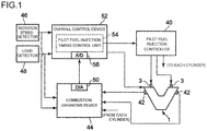
- Fig. 1 is a view showing an overall configuration of an embodiment of the present invention applied to a pilot fuel injection device 3 that injects pilot fuel into a precombustion chamber 7 of a V type multiple cylinder gas engine 1.
- Fig. 4 shows a structure of the pilot fuel injection device 3.
- the pilot fuel injection device 3 is constituted by a main body 5 and a precombustion chamber cap 9 including a precombustion chamber 7.
- the precombustion chamber cap 9 is fixed to a cylinder head 11 by fastening the main body 5 to the cylinder head 11.
- a plurality of precombustion chamber discharge ports 17 connecting the precombustion chamber 7, which is formed in an interior of the precombustion chamber cap 9, to a main combustion chamber 15 are formed in a circumferential direction of the precombustion chamber cap 9.
- the main combustion chamber 15 is formed by a piston 30, the cylinder head 11, and a cylinder block 32, and a piston cavity 34 is formed in an upper surface of the piston 30.
- a pilot fuel injection valve 19 is provided in an interior of the main body 5, and a liquid fuel such as light oil is injected into the precombustion chamber 7 through a liquid fuel passage 21.
- a pilot injection timing and a pilot injection amount are controlled in accordance with a command from a pilot fuel injection controller 40, whereby the pilot fuel injection valve 19 opens and closes such that the liquid fuel (the pilot fuel) is injected into the precombustion chamber 7 through the precombustion chamber discharge ports 17.
- the pilot fuel injection valve 19 opens and closes such that the liquid fuel (the pilot fuel) is injected into the precombustion chamber 7 through the precombustion chamber discharge ports 17.
- the lean air-fuel mixture charged into the precombustion chamber 7 from the main combustion chamber 15 through the precombustion chamber discharge ports 17 is ignited and burned so as to form a torch flame 23, and the torch flame 23 is discharged into the main combustion chamber 15 through the precombustion chamber discharge ports 17.
- an in-cylinder pressure detector 42 (see Fig. 4 ) is provided in each cylinder to detect an in-cylinder pressure in the main combustion chamber 15, and a detected value of variation in the in-cylinder pressure of each cylinder is input into a combustion diagnosis device 44. Signals from an engine rotation speed detector 46 and an engine load detector 48 are also input, and on the basis of these input signals, a combustion condition of the engine 1 is diagnosed in relation to each cylinder.
- the combustion diagnosis device 44 diagnoses whether or not an in-cylinder pressure p is in an H (high) range or an L (low) range relative to an N (optimal) range, and outputs a corresponding diagnosis result.
- the output diagnosis result is converted from a digital signal (D) into an analog signal (A) by a D/A converter 50, whereupon, as shown in Fig. 6 , for example, the analog signal is output as a current value of 11 to 12 in the case of L (low), a current value of n1 to n2 in the case of N (optimal), and a current value of h1 to h2 in the case of H (high).
- the in-cylinder pressure is slightly lower than the optimal in-cylinder pressure when the output current value is between 11 and 12, and that the in-cylinder pressure is slightly higher than the optimal in-cylinder pressure when the output current value is between h1 and h2.
- the D/A-converted output signal from the combustion diagnosis device 44 is input into an overall control device 52.
- the overall control device 52 controls an overall operating condition of the engine 1, including controlling an engine rotation speed by controlling a fuel gas supply solenoid valve, not shown in the drawings, in order to adjust an amount of gas fuel supplied to the intake passage 38 (see Fig. 4 ), controlling an air-fuel ratio by controlling a rotation speed of a turbo charger, not shown in the drawings, provided in the intake passage 38, and so on.
- the signal output from the combustion diagnosis device 44 is input into a pilot fuel injection timing control unit (a pilot fuel injection timing control device) 54 included in the overall control device 52 in order to control a pilot fuel injection timing.
- a result of this control is output to a pilot fuel injection controller 40, whereupon the pilot fuel injection controller 40 operates a pilot fuel injection device 3 provided in each cylinder.
- pilot fuel injection controller 40 and the pilot fuel injection timing control unit 54 together constitute a fuel injection control device for the pilot fuel.
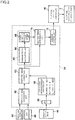
- an analog signal from the combustion diagnosis device 44 is converted into a digital signal by an A/D converter 58 and then input into a combustion diagnosis result analysis unit 59.
- the combustion diagnosis result analysis unit 59 sets correction amounts on the basis of the diagnosis result such that when the in-cylinder pressure p is at the high H level, the pilot fuel injection timing is set at - ⁇ 1 (retardation by ⁇ 1), and when the in-cylinder pressure p is at the low L level, the pilot fuel injection timing is set at + ⁇ 2 (advancement by ⁇ 2).
- An output from the combustion diagnosis result analysis unit 59 is input into an injection timing correction unit 62.
- the correction amounts may be set at fixed values or varied in accordance with the operating condition of the engine 1.
- the correction amounts are set to be variable, data corresponding to operating conditions are stored on a map in advance.
- An injection timing calculation unit 60 then calculates a preset standard pilot fuel injection timing corresponding to the operating condition on the basis of detection signals indicating the rotation speed and the load of the engine 1, detected by the rotation speed detector 46 and the load detector 48, using a map or the like.
- the injection timing correction unit 62 calculates a corrected pilot fuel injection timing by adding the correction amount timing (- ⁇ 1, + ⁇ 2) input from the combustion diagnosis result analysis unit 59 to the standard pilot fuel injection timing.
- the injection timing correction unit 62 adds the corrected timing to the standard pilot fuel injection timing. During all other corrections, for example a second or third correction, however, the corrected timing is added to an immediately preceding injection timing such that the correction amount timing (- ⁇ 1, + ⁇ 2) increases cumulatively until a signal indicating the N (optimal) determination level is output by the combustion diagnosis result analysis unit 59.
- An allowable correction range setting unit 64 sets an allowable range of the corrected fuel injection timing calculated by the injection timing correction unit 62.
- the allowable correction range setting unit 64 is constituted by an average timing calculation unit 66 and an upper/lower limit allowable value setting unit 68.
- the average timing calculation unit 66 determines an arithmetic mean of data indicating past fuel injection timings of all of the cylinders of the engine 1 in relation to cylinders including the cylinder diagnosed by the combustion diagnosis device 44 as having less than optimal combustion and all of the cylinders diagnosed as being optimal.
- the arithmetic mean value is determined using the previous (immediately preceding) injection timings as the past data. Since the allowable correction range is set on the basis of immediately preceding fuel injection data for a plurality of cylinders, the allowable correction range does not have to be stored in advance as a map, and therefore a capacity of a storage unit can be reduced and a control device can be simplified.
- the upper/lower limit allowable value setting unit 68 applies an upper/lower limit value allowable range to the average value calculated by the average timing calculation unit 66.
- An upper limit value of the upper/lower limit allowable range is set on the basis of experiments or simulation calculations as a value at which high pressure causes a mechanical abnormality such as damage to occur in the cylinder.
- a lower limit value is set on the basis of experiments or simulation calculations as a value at which misfiring results.
- + ⁇ (advancement by ⁇ , - ⁇ (retardation by ⁇ ) is set as the upper/lower limit allowable range relative to an average timing M.
- an average value of the fuel injection timings of all of the cylinders over a fixed past time period may be calculated, whereupon an upper/lower limit allowable range is attached to the average value obtained as a calculation result.
- the average value is calculated on the basis of pilot fuel injection data from a fixed past time period of one hour, one day, one month, or the like, for example.
- the allowable correction range can be set to reflect a history of past operating conditions, and as a result, a more appropriate allowable correction range can be set.
- An injection timing determination unit 70 determines whether or not the newly corrected pilot fuel injection timing calculated by the injection timing correction unit 62 is within the allowable correction range set by the allowable correction range setting unit 64.
- a command control unit 72 When the injection timing determination unit 70 determines that the newly corrected pilot fuel injection timing corrected by the injection timing correction unit 62 is within the allowable correction range, a command control unit 72 outputs a signal indicating the newly corrected pilot fuel injection timing to the pilot fuel injection controller 40, whereupon the pilot fuel injection controller 40 operates the pilot fuel injection devices 3.
- the command control unit 72 When the injection timing determination unit 70 determines that the newly corrected pilot fuel injection timing calculated by the injection timing correction unit 62 is not within the allowable correction range, on the other hand, the command control unit 72 outputs a signal indicating the previously implemented (immediately preceding) pilot fuel injection timing to the pilot fuel injection controller 40, whereupon the pilot fuel injection controller 40 operates the pilot fuel injection devices 3 such that a current operation is maintained.
- the pilot fuel injection controller 40 When the determination result obtained by the injection timing determination unit 70 is within the allowable correction range, the pilot fuel injection controller 40 is operated at the corrected pilot fuel injection timing obtained during the current correction, and when the determination result obtained by the injection timing determination unit 70 is outside the allowable correction range, the pilot fuel injection controller 40 is operated at the previously executed (immediately preceding) pilot fuel injection timing. In so doing, correction of the fuel injection timing based on the diagnosis result from the combustion diagnosis device 44 can be maintained within an appropriate range.
- a part F1 indicating the diagnosis control executed by the combustion diagnosis device 44 is integrated with a part F2 indicating the pilot fuel injection timing control executed by the pilot fuel injection timing control unit 54 of the overall control device 52.
- step S1 input signals from the in-cylinder pressure detector 42 and the rotation speed detector 46 and load detector 48 of the engine 1 are read.
- step S2 a determination is made as to whether or not the detected in-cylinder pressure exceeds the optimal range. When the determination is affirmative, this means that the in-cylinder pressure exceeds the optimal range, and therefore a signal indicating the H (high) range of Fig. 6 is output.
- step S5 a further determination is made in step S5 as to whether or not the in-cylinder pressure is lower than the optimal range. When the determination is affirmative, this means that the in-cylinder pressure is lower than the optimal range, and therefore a signal indicating the L (low) range of Fig. 6 is output.
- step S5 when the determination of step S5 is negative, this means that the in-cylinder pressure is in the optimal range, and therefore a signal indicating the N (optimal) range of Fig. 6 is output.
- N (optimal) range signal When the N (optimal) range signal is output, this means that combustion is within the optimal range, and therefore the control is terminated in step S9 without either advancing or retarding the pilot fuel injection timing.
- step S2 When it is determined in step S2 that the in-cylinder pressure exceeds the optimal range, the control advances to step S3, where a determination is made as to whether or not the newly corrected pilot fuel injection timing is within the allowable correction range.
- step S3 a determination is made in step S3 as to whether or not the newly corrected pilot fuel injection timing deviates from the average timing M by less than the retardation value ⁇ .
- step S4 a command to retard the pilot fuel injection timing to the newly corrected pilot fuel injection timing is issued.
- step S9 a command to retard the pilot fuel injection timing to the newly corrected pilot fuel injection timing is issued.
- step S9 the determination of step S3 is negative, on the other hand, this means that the newly corrected pilot fuel injection timing is far removed from the average timing M, and therefore injection is performed at the previous (immediately preceding) pilot fuel injection timing without correcting the pilot fuel injection timing to the retardation side.
- step S5 When it is determined in step S5 that the in-cylinder pressure is lower than the optimal range, the control advances to step S6, where a determination is made as to whether or not the newly corrected pilot fuel injection timing is within the allowable correction range. More specifically, using the average timing M and the upper limit allowable advancement value ⁇ , a determination is made in step S6 as to whether or not the newly corrected pilot fuel injection timing deviates from the average timing M by less than the advancement value ⁇ .
- step S7 a command to advance the pilot fuel injection timing to the newly corrected pilot fuel injection timing is issued.
- step S9 a command to advance the pilot fuel injection timing to the newly corrected pilot fuel injection timing is issued.
- step S9 a command to advance the pilot fuel injection timing to the newly corrected pilot fuel injection timing is issued.
- step S9 a command to advance the pilot fuel injection timing to the newly corrected pilot fuel injection timing is issued.
- step S9 the determination of step S6 is negative, on the other hand, this means that the newly corrected pilot fuel injection timing is far removed from the average timing M, and therefore injection is performed at the previous (immediately preceding) pilot fuel injection timing without correcting the pilot fuel injection timing to the advancement side.
- the gas engine 1 to which the pilot fuel injection device 3 for injecting pilot fuel into the precombustion chamber 7 is attached was described as an example, but the present invention may be applied to any engine that corrects a fuel injection timing cumulatively until optimal combustion is restored on the basis of a diagnosis result from a combustion diagnosis device, and therefore a corrected operation based on a signal from the combustion diagnosis device can be improved in safety and reliability likewise when the present invention is applied to an ignition system of a gas engine that generates a torch flame when gas fuel is injected into a precombustion chamber and ignited by a spark plug.
- the present invention even when a signal indicating a combustion diagnosis result transmitted to a fuel injection control device (an injection timing control device) from a combustion diagnosis device that determines whether or not combustion is optimal, including whether or not knocking or misfiring has occurred in an engine, is output or input while indicating an incorrect diagnosis result, correction of a fuel injection timing on the basis of the combustion diagnosis result can be maintained within an allowable range, and as a result, a corrected operation based on the signal from the combustion diagnosis device can be improved in safety and reliability.
- the present invention can therefore be applied to a multiple cylinder engine that includes a combustion diagnosis device and corrects a combustion condition cumulatively on the basis of a signal from the combustion diagnosis device.
Landscapes
- Engineering & Computer Science (AREA)
- Chemical & Material Sciences (AREA)
- Combustion & Propulsion (AREA)
- Mechanical Engineering (AREA)
- General Engineering & Computer Science (AREA)
- Electrical Control Of Air Or Fuel Supplied To Internal-Combustion Engine (AREA)
- Combined Controls Of Internal Combustion Engines (AREA)
Claims (4)
- Procédé de commande d'un calage de l'injection pilote lorsqu'une anomalie se produit dans un signal de diagnostic de combustion concernant un moteur (1) possédant un dispositif de diagnostic de combustion (44) qui détermine si la combustion est optimale ou non, et un dispositif de commande d'injection de carburant (40) qui commande un dispositif d'injection de carburant (3) lors de la réception d'un résultat de diagnostic provenant du dispositif de diagnostic de combustion, dans lequel le moteur (1) est un moteur à gaz du type à plusieurs cylindres incluant une chambre de précombustion (7), une flamme torche étant déchargée dans une chambre de combustion principale (15) à travers des orifices de décharge de chambre de précombustion (17), et un calage de l'injection de carburant est un calage auquel du carburant pilote est injecté dans la chambre de précombustion, et le procédé comprenant les étapes consistant à :diagnostiquer un état de combustion des cylindres respectifs en utilisant le dispositif de diagnostic de combustion (44) sur une base d'une pression régnant dans les cylindres, d'une vitesse de rotation du moteur et d'une charge sur le moteur ;corriger de manière répétée un calage de l'injection de carburant standard réglé à l'avance sur la base de la vitesse de rotation du moteur et de la charge sur le moteur, en ce qui concerne un cylindre dans lequel la combustion est déterminée comme étant moins qu'optimale, d'une manière telle qu'une quantité de correction s'accumule jusqu'à ce que la combustion soit déterminée comme étant optimale ;le procédé étant caractérisé par le fait de :régler une plage admissible d'un calage de l'injection de carburant sur la base de données indiquant des calages passés de l'injection de carburant de la totalité de la pluralité de cylindres en appliquant une plage admissible de valeurs limites supérieure/inférieure à une valeur moyenne arithmétique des données indiquant les calages passés de l'injection de carburant de la totalité d'une pluralité de cylindres du moteur;déterminer si un calage de l'injection nouvellement corrigé est ou non à l'intérieur de la plage admissible ; etmettre en oeuvre le dispositif d'injection de carburant (3) au calage de l'injection nouvellement corrigé lorsqu'un résultat de la détermination est à l'intérieur de la plage admissible ; etlorsque le résultat de la détermination est à l'extérieur de la plage admissible, le dispositif de commande de l'injection de carburant (40) est mis en oeuvre à un calage de l'injection précédent.
- Procédé de commande d'un calage de l'injection pilote lorsqu'une anomalie se produit dans un signal de diagnostic de combustion concernant un moteur selon la revendication 1, caractérisé en ce que, dans l'étape de réglage de la plage admissible, la plage admissible est réglée en calculant une valeur moyenne de calages de l'injection de carburant immédiatement précédents de tous les cyclindres, et en attachant une plage admissible de limites supérieure/inférieure à la valeur moyenne calculée.
- Procédé de commande d'un calage de l'injection pilote lorsqu'une anomalie se produit dans un signal de diagnostic de combustion concernant un moteur selon la revendication 1, caractérisé en ce que, dans l'étape de réglage de la plage admissible, la plage admissible est réglée en calculant une valeur moyenne des calages de l'injection de carburant de la totalité des cylindres sur un laps de temps passé fixé, et en attachant une plage admissible de limites supérieure/inférieure à la valeur moyenne obtenue comme résultat du calcul.
- Dispositif (54) pour la commande d'un calage de l'injection pilote lorsqu'une anomalie se produit dans un signal de diagnostic de combustion concernant un moteur (1) possédant un dispositif de diagnostic de combustion (44) qui détermine si la combustion est optimale ou non, et un dispositif de commande d'injection de carburant (40) qui commande un dispositif d'injection de carburant (3) lors de la réception d'un résultat de diagnostic provenant du dispositif de diagnostic de combustion,
dans lequel
le moteur (1) est un moteur à gaz du type à plusieurs cylindres incluant une chambre de précombustion (7), une flamme torche étant déchargée dans une chambre de combustion principale (15) à travers des orifices de décharge de chambre de précombustion (17), et un calage de l'injection de carburant est un calage auquel du carburant pilote est injecté dans la chambre de précombustion, et le dispositif comprenant :une unité de calcul de calage de l'injection (60) qui calcule un calage de l'injection de carburant standard préréglé sur la base d'une vitesse de rotation du moteur et d'une charge sur le moteur;une unité de correction de calage de l'injection (62) qui corrige de manière répétée le calage de l'injection de carburant standard calculé par l'unité de calcul de calage de l'injection (60) en ce qui concerne un cylindre dans lequel la combustion est déterminée par le dispositif de diagnostic de combustion (44) sur une base d'une pression régnant dans les cylindres, d'une vitesse de rotation de moteur et d'une charge sur le moteur,comme étant moins qu'optimale, d'une manière telle qu'une quantité de correction s'accumule jusqu'à ce que la combustion soit déterminée comme étant optimale ;le dispositif étant caractérisé par :une unité de réglage de plage admissible (64) qui est constituée par une unité de calcul de calage moyen (66) et par une unité de réglage de valeurs limites supérieure/inférieure admissibles (68), et qui règle une plage admissible du calage de l'injection de carburant sur la base de données indiquant des calages passés de l'injection de carburant de la totalité d'une pluralité de cylindres ;une unité de détermination de calage de l'injection (70) qui détermine si un calage en vigueur de l'injection de carburant corrigé par l'unité de correction de calage de l'injection (62) est ou non à l'intérieur de la plage admissible réglée par l'unité de réglage de plage admissible (64) ; etune unité de commande d'ordres (72) qui envoie un ordre au dispositif de commande de d'injection de carburant (40) pour exécuter l'injection au calage de l'injection de carburant nouvellement corrigé lorsque l'unité de détermination détermine que le calage de l'injection de carburant nouvellement corrigé est à l'intérieur de la plage admissible ; etlorsque le résultat de détermination obtenu par l'unité de détermination de calage de l'injection est à l'extérieur de la plage admissible, l'unité de commande d'ordres sort un ordre vers le dispositif de commande d'injection de carburant pour exécuter l'injection à un calage précédent de l'injection de carburant.
Applications Claiming Priority (2)
| Application Number | Priority Date | Filing Date | Title |
|---|---|---|---|
| JP2011079791A JP5675466B2 (ja) | 2011-03-31 | 2011-03-31 | エンジンの燃焼診断信号異常時のパイロット噴射タイミング制御方法および装置 |
| PCT/JP2012/054020 WO2012132629A1 (fr) | 2011-03-31 | 2012-02-20 | Procédé et dispositif permettant de contrôler le calage de l'injection pilote lorsque le signal de diagnostic de la combustion du moteur est anormal |
Publications (3)
| Publication Number | Publication Date |
|---|---|
| EP2693029A1 EP2693029A1 (fr) | 2014-02-05 |
| EP2693029A4 EP2693029A4 (fr) | 2015-12-16 |
| EP2693029B1 true EP2693029B1 (fr) | 2017-06-28 |
Family
ID=46930390
Family Applications (1)
| Application Number | Title | Priority Date | Filing Date |
|---|---|---|---|
| EP12764757.6A Not-in-force EP2693029B1 (fr) | 2011-03-31 | 2012-02-20 | Procédé et dispositif permettant de contrôler le calage de l'injection pilote lorsque le signal de diagnostic de la combustion du moteur est anormal |
Country Status (6)
| Country | Link |
|---|---|
| US (1) | US20140048046A1 (fr) |
| EP (1) | EP2693029B1 (fr) |
| JP (1) | JP5675466B2 (fr) |
| KR (1) | KR101481931B1 (fr) |
| CN (1) | CN103443430B (fr) |
| WO (1) | WO2012132629A1 (fr) |
Families Citing this family (8)
| Publication number | Priority date | Publication date | Assignee | Title |
|---|---|---|---|---|
| JP5700790B2 (ja) * | 2011-01-14 | 2015-04-15 | ヤンマー株式会社 | ガス圧力検知機構の異常発生の検知機能を有するガスエンジンシステム |
| JP5951537B2 (ja) * | 2013-03-19 | 2016-07-13 | 三菱重工業株式会社 | ガスエンジンの燃焼制御装置 |
| DE102014007009B4 (de) * | 2014-05-13 | 2018-01-18 | Mtu Friedrichshafen Gmbh | Motorüberwachung mittels zylinderindividueller Drucksensoren vorzüglich bei Magergasmotoren mit gespülter Vorkammer |
| US9556832B1 (en) * | 2015-09-01 | 2017-01-31 | Combustion Engine Technologies, LLC | Adiabatic fuel injection-ignition method and device |
| US9441573B1 (en) | 2015-12-09 | 2016-09-13 | Combustion Engine Technologies, LLC | Two-stroke reciprocating piston injection-ignition or compression-ignition engine |
| DE102017216121A1 (de) * | 2017-09-13 | 2019-03-14 | Volkswagen Aktiengesellschaft | Verfahren zum Betreiben eines Verbrennungsmotors sowie Verbrennungsmotor |
| JP2021161974A (ja) * | 2020-03-31 | 2021-10-11 | 本田技研工業株式会社 | 燃料噴射制御装置 |
| CN113153553B (zh) * | 2021-03-23 | 2022-08-26 | 长沙理工大学 | 电控喷油器喷油量线性特性优化方法 |
Family Cites Families (21)
| Publication number | Priority date | Publication date | Assignee | Title |
|---|---|---|---|---|
| JPS5843584B2 (ja) * | 1979-02-08 | 1983-09-28 | 日産自動車株式会社 | 点火時期制御装置 |
| DE19621297C1 (de) * | 1996-05-28 | 1997-12-04 | Man B & W Diesel Ag | Einrichtung zur Steuerung/Regelung der Zündöl-Einspritzung eines Gasmotors |
| US5983630A (en) * | 1997-07-01 | 1999-11-16 | Toyota Jidosha Kabushiki Kaisha | Fuel injecting device for an engine |
| JP3760583B2 (ja) * | 1997-07-31 | 2006-03-29 | トヨタ自動車株式会社 | 燃料噴射装置 |
| US6912992B2 (en) * | 2000-12-26 | 2005-07-05 | Cummins Westport Inc. | Method and apparatus for pilot fuel introduction and controlling combustion in gaseous-fuelled internal combustion engine |
| CN1288335C (zh) * | 2001-12-25 | 2006-12-06 | 新泻原动机株式会社 | 双燃料发动机 |
| JP4248178B2 (ja) | 2001-12-25 | 2009-04-02 | トヨタ自動車株式会社 | 内燃機関 |
| JP4089244B2 (ja) * | 2002-03-01 | 2008-05-28 | 株式会社デンソー | 内燃機関用噴射量制御装置 |
| JP3886949B2 (ja) * | 2003-08-20 | 2007-02-28 | 三菱重工業株式会社 | ガスエンジンの燃料制御装置及び燃料制御方法 |
| US7007661B2 (en) * | 2004-01-27 | 2006-03-07 | Woodward Governor Company | Method and apparatus for controlling micro pilot fuel injection to minimize NOx and UHC emissions |
| EP1607609B1 (fr) * | 2004-06-15 | 2009-03-25 | C.R.F. Società Consortile per Azioni | Système de régulation pour contrôler la combustion dans un moteur diesel fonctionnant avec combustion prémélangée |
| JP2006183548A (ja) * | 2004-12-27 | 2006-07-13 | Nippon Soken Inc | 内燃機関の制御装置 |
| JP2006299832A (ja) * | 2005-04-15 | 2006-11-02 | Toyota Industries Corp | ディーゼルエンジンにおける燃料噴射制御装置 |
| FR2890117B1 (fr) * | 2005-08-30 | 2009-07-10 | Peugeot Citroen Automobiles Sa | Procede et systeme de controle du fonctionnement d'un moteur diesel de vehicule automobile |
| JP4743030B2 (ja) * | 2006-07-07 | 2011-08-10 | 株式会社デンソー | ディーゼル機関用燃料噴射制御装置 |
| JP4779975B2 (ja) * | 2007-01-10 | 2011-09-28 | 株式会社デンソー | エンジン制御装置 |
| JP4851978B2 (ja) * | 2007-03-29 | 2012-01-11 | 新潟原動機株式会社 | ガスエンジンにおける燃焼制御方法およびその装置 |
| JP4946900B2 (ja) * | 2007-04-02 | 2012-06-06 | 株式会社デンソー | 圧縮着火式筒内噴射エンジンの燃焼制御装置及びエンジン制御システム |
| DE102007053406B3 (de) * | 2007-11-09 | 2009-06-04 | Continental Automotive Gmbh | Verfahren und Vorrichtung zur Durchführung sowohl einer Adaption wie einer Diagnose bei emissionsrelevanten Steuereinrichtungen in einem Fahrzeug |
| US7899601B2 (en) * | 2009-03-02 | 2011-03-01 | GM Global Technology Operations LLC | Methodology for extending the high load limit of HCCI operation by adjusting injection timing and spark timing |
| JP5195530B2 (ja) | 2009-03-04 | 2013-05-08 | 日産自動車株式会社 | ディーゼルエンジンの制御装置 |
-
2011
- 2011-03-31 JP JP2011079791A patent/JP5675466B2/ja not_active Expired - Fee Related
-
2012
- 2012-02-20 EP EP12764757.6A patent/EP2693029B1/fr not_active Not-in-force
- 2012-02-20 US US14/008,188 patent/US20140048046A1/en not_active Abandoned
- 2012-02-20 WO PCT/JP2012/054020 patent/WO2012132629A1/fr active Application Filing
- 2012-02-20 CN CN201280014236.XA patent/CN103443430B/zh not_active Expired - Fee Related
- 2012-02-20 KR KR1020137024917A patent/KR101481931B1/ko active IP Right Grant
Non-Patent Citations (1)
| Title |
|---|
| None * |
Also Published As
| Publication number | Publication date |
|---|---|
| CN103443430B (zh) | 2016-01-20 |
| WO2012132629A1 (fr) | 2012-10-04 |
| EP2693029A1 (fr) | 2014-02-05 |
| US20140048046A1 (en) | 2014-02-20 |
| JP5675466B2 (ja) | 2015-02-25 |
| KR20130127516A (ko) | 2013-11-22 |
| EP2693029A4 (fr) | 2015-12-16 |
| JP2012215087A (ja) | 2012-11-08 |
| CN103443430A (zh) | 2013-12-11 |
| KR101481931B1 (ko) | 2015-01-12 |
Similar Documents
| Publication | Publication Date | Title |
|---|---|---|
| EP2693029B1 (fr) | Procédé et dispositif permettant de contrôler le calage de l'injection pilote lorsque le signal de diagnostic de la combustion du moteur est anormal | |
| EP1979607B1 (fr) | Capteur de qualité de combustible virtuel | |
| EP3286541B1 (fr) | Détection et atténuation de caractéristiques de combustion anormales | |
| EP1538325B1 (fr) | Dispositif de commande de moteur a combustion interne | |
| EP1835160B1 (fr) | Appareil de contrôle d'injection de carburant pour moteur à combustion interne | |
| EP2031232B1 (fr) | Moyen de détection d'indice de cétane et moteur associé | |
| US5983714A (en) | System for detecting failure of fuel pressure sensor | |
| US6694960B2 (en) | Method and arrangement for determining cylinder-individual differences of a control variable in a multi-cylinder internal combustion engine | |
| EP2000655B1 (fr) | Procédé de fonctionnement d'un moteur en cas de combustion anormale et dispositif de commande de fonctionnement | |
| EP0851107A2 (fr) | Commande de rapport air/carburant et de moteur à combustion basée sur la pression dans les cylindres | |
| JP6213532B2 (ja) | 内燃機関の制御装置 | |
| US20150159569A1 (en) | Method and apparatus for detecting combustion phase of engine by angular acceleration signal and combustion data of single cylinder | |
| JP2010127172A (ja) | 筒内圧センサ特性検出装置 | |
| US20210324814A1 (en) | Control Device and Diagnostic Method for Internal Combustion Engine | |
| JPWO2017073340A1 (ja) | 内燃機関制御装置 | |
| KR102250296B1 (ko) | 다기통 내연기관의 기통 편차 모니터링장치 및 그 방법 | |
| JP5737196B2 (ja) | 内燃機関の制御装置 | |
| US20110320107A1 (en) | Fuel Injection Control Device for Engine | |
| US11098671B2 (en) | Combustion control device | |
| JP6485129B2 (ja) | 天然ガスエンジン及びその運転方法 | |
| JPH05113147A (ja) | 内燃機関の制御装置 | |
| JPS62258150A (ja) | 空燃比制御装置 |
Legal Events
| Date | Code | Title | Description |
|---|---|---|---|
| PUAI | Public reference made under article 153(3) epc to a published international application that has entered the european phase |
Free format text: ORIGINAL CODE: 0009012 |
|
| 17P | Request for examination filed |
Effective date: 20130926 |
|
| AK | Designated contracting states |
Kind code of ref document: A1 Designated state(s): AL AT BE BG CH CY CZ DE DK EE ES FI FR GB GR HR HU IE IS IT LI LT LU LV MC MK MT NL NO PL PT RO RS SE SI SK SM TR |
|
| DAX | Request for extension of the european patent (deleted) | ||
| RA4 | Supplementary search report drawn up and despatched (corrected) |
Effective date: 20151118 |
|
| RIC1 | Information provided on ipc code assigned before grant |
Ipc: F02D 41/30 20060101ALI20151112BHEP Ipc: F02D 41/38 20060101ALI20151112BHEP Ipc: F02D 41/22 20060101ALI20151112BHEP Ipc: F02D 35/02 20060101ALI20151112BHEP Ipc: F02D 41/00 20060101ALI20151112BHEP Ipc: F02D 41/24 20060101ALI20151112BHEP Ipc: F02D 41/40 20060101AFI20151112BHEP |
|
| 17Q | First examination report despatched |
Effective date: 20160905 |
|
| GRAP | Despatch of communication of intention to grant a patent |
Free format text: ORIGINAL CODE: EPIDOSNIGR1 |
|
| INTG | Intention to grant announced |
Effective date: 20161223 |
|
| GRAS | Grant fee paid |
Free format text: ORIGINAL CODE: EPIDOSNIGR3 |
|
| GRAJ | Information related to disapproval of communication of intention to grant by the applicant or resumption of examination proceedings by the epo deleted |
Free format text: ORIGINAL CODE: EPIDOSDIGR1 |
|
| GRAL | Information related to payment of fee for publishing/printing deleted |
Free format text: ORIGINAL CODE: EPIDOSDIGR3 |
|
| GRAR | Information related to intention to grant a patent recorded |
Free format text: ORIGINAL CODE: EPIDOSNIGR71 |
|
| GRAA | (expected) grant |
Free format text: ORIGINAL CODE: 0009210 |
|
| INTC | Intention to grant announced (deleted) | ||
| AK | Designated contracting states |
Kind code of ref document: B1 Designated state(s): AL AT BE BG CH CY CZ DE DK EE ES FI FR GB GR HR HU IE IS IT LI LT LU LV MC MK MT NL NO PL PT RO RS SE SI SK SM TR |
|
| INTG | Intention to grant announced |
Effective date: 20170523 |
|
| REG | Reference to a national code |
Ref country code: GB Ref legal event code: FG4D |
|
| REG | Reference to a national code |
Ref country code: CH Ref legal event code: EP |
|
| REG | Reference to a national code |
Ref country code: AT Ref legal event code: REF Ref document number: 905071 Country of ref document: AT Kind code of ref document: T Effective date: 20170715 |
|
| REG | Reference to a national code |
Ref country code: IE Ref legal event code: FG4D |
|
| REG | Reference to a national code |
Ref country code: DE Ref legal event code: R096 Ref document number: 602012033984 Country of ref document: DE |
|
| GRAT | Correction requested after decision to grant or after decision to maintain patent in amended form |
Free format text: ORIGINAL CODE: EPIDOSNCDEC |
|
| PG25 | Lapsed in a contracting state [announced via postgrant information from national office to epo] |
Ref country code: GR Free format text: LAPSE BECAUSE OF FAILURE TO SUBMIT A TRANSLATION OF THE DESCRIPTION OR TO PAY THE FEE WITHIN THE PRESCRIBED TIME-LIMIT Effective date: 20170929 Ref country code: LT Free format text: LAPSE BECAUSE OF FAILURE TO SUBMIT A TRANSLATION OF THE DESCRIPTION OR TO PAY THE FEE WITHIN THE PRESCRIBED TIME-LIMIT Effective date: 20170628 Ref country code: NO Free format text: LAPSE BECAUSE OF FAILURE TO SUBMIT A TRANSLATION OF THE DESCRIPTION OR TO PAY THE FEE WITHIN THE PRESCRIBED TIME-LIMIT Effective date: 20170928 Ref country code: HR Free format text: LAPSE BECAUSE OF FAILURE TO SUBMIT A TRANSLATION OF THE DESCRIPTION OR TO PAY THE FEE WITHIN THE PRESCRIBED TIME-LIMIT Effective date: 20170628 |
|
| REG | Reference to a national code |
Ref country code: NL Ref legal event code: MP Effective date: 20170628 |
|
| REG | Reference to a national code |
Ref country code: LT Ref legal event code: MG4D |
|
| PG25 | Lapsed in a contracting state [announced via postgrant information from national office to epo] |
Ref country code: SE Free format text: LAPSE BECAUSE OF FAILURE TO SUBMIT A TRANSLATION OF THE DESCRIPTION OR TO PAY THE FEE WITHIN THE PRESCRIBED TIME-LIMIT Effective date: 20170628 Ref country code: BG Free format text: LAPSE BECAUSE OF FAILURE TO SUBMIT A TRANSLATION OF THE DESCRIPTION OR TO PAY THE FEE WITHIN THE PRESCRIBED TIME-LIMIT Effective date: 20170928 Ref country code: NL Free format text: LAPSE BECAUSE OF FAILURE TO SUBMIT A TRANSLATION OF THE DESCRIPTION OR TO PAY THE FEE WITHIN THE PRESCRIBED TIME-LIMIT Effective date: 20170628 Ref country code: LV Free format text: LAPSE BECAUSE OF FAILURE TO SUBMIT A TRANSLATION OF THE DESCRIPTION OR TO PAY THE FEE WITHIN THE PRESCRIBED TIME-LIMIT Effective date: 20170628 Ref country code: RS Free format text: LAPSE BECAUSE OF FAILURE TO SUBMIT A TRANSLATION OF THE DESCRIPTION OR TO PAY THE FEE WITHIN THE PRESCRIBED TIME-LIMIT Effective date: 20170628 |
|
| PG25 | Lapsed in a contracting state [announced via postgrant information from national office to epo] |
Ref country code: EE Free format text: LAPSE BECAUSE OF FAILURE TO SUBMIT A TRANSLATION OF THE DESCRIPTION OR TO PAY THE FEE WITHIN THE PRESCRIBED TIME-LIMIT Effective date: 20170628 Ref country code: CZ Free format text: LAPSE BECAUSE OF FAILURE TO SUBMIT A TRANSLATION OF THE DESCRIPTION OR TO PAY THE FEE WITHIN THE PRESCRIBED TIME-LIMIT Effective date: 20170628 Ref country code: SK Free format text: LAPSE BECAUSE OF FAILURE TO SUBMIT A TRANSLATION OF THE DESCRIPTION OR TO PAY THE FEE WITHIN THE PRESCRIBED TIME-LIMIT Effective date: 20170628 Ref country code: RO Free format text: LAPSE BECAUSE OF FAILURE TO SUBMIT A TRANSLATION OF THE DESCRIPTION OR TO PAY THE FEE WITHIN THE PRESCRIBED TIME-LIMIT Effective date: 20170628 |
|
| PG25 | Lapsed in a contracting state [announced via postgrant information from national office to epo] |
Ref country code: SM Free format text: LAPSE BECAUSE OF FAILURE TO SUBMIT A TRANSLATION OF THE DESCRIPTION OR TO PAY THE FEE WITHIN THE PRESCRIBED TIME-LIMIT Effective date: 20170628 Ref country code: IS Free format text: LAPSE BECAUSE OF FAILURE TO SUBMIT A TRANSLATION OF THE DESCRIPTION OR TO PAY THE FEE WITHIN THE PRESCRIBED TIME-LIMIT Effective date: 20171028 Ref country code: IT Free format text: LAPSE BECAUSE OF FAILURE TO SUBMIT A TRANSLATION OF THE DESCRIPTION OR TO PAY THE FEE WITHIN THE PRESCRIBED TIME-LIMIT Effective date: 20170628 Ref country code: ES Free format text: LAPSE BECAUSE OF FAILURE TO SUBMIT A TRANSLATION OF THE DESCRIPTION OR TO PAY THE FEE WITHIN THE PRESCRIBED TIME-LIMIT Effective date: 20170628 Ref country code: PL Free format text: LAPSE BECAUSE OF FAILURE TO SUBMIT A TRANSLATION OF THE DESCRIPTION OR TO PAY THE FEE WITHIN THE PRESCRIBED TIME-LIMIT Effective date: 20170628 |
|
| REG | Reference to a national code |
Ref country code: DE Ref legal event code: R097 Ref document number: 602012033984 Country of ref document: DE |
|
| PG25 | Lapsed in a contracting state [announced via postgrant information from national office to epo] |
Ref country code: DK Free format text: LAPSE BECAUSE OF FAILURE TO SUBMIT A TRANSLATION OF THE DESCRIPTION OR TO PAY THE FEE WITHIN THE PRESCRIBED TIME-LIMIT Effective date: 20170628 |
|
| PLBE | No opposition filed within time limit |
Free format text: ORIGINAL CODE: 0009261 |
|
| STAA | Information on the status of an ep patent application or granted ep patent |
Free format text: STATUS: NO OPPOSITION FILED WITHIN TIME LIMIT |
|
| 26N | No opposition filed |
Effective date: 20180329 |
|
| REG | Reference to a national code |
Ref country code: DE Ref legal event code: R081 Ref document number: 602012033984 Country of ref document: DE Owner name: MITSUBISHI HEAVY INDUSTRIES ENGINE TURBOCHAR, JP Free format text: FORMER OWNER: MITSUBISHI HEAVY INDUSTRIES, LTD., TOKYO, JP Ref country code: DE Ref legal event code: R082 Ref document number: 602012033984 Country of ref document: DE Representative=s name: HOFFMANN - EITLE PATENT- UND RECHTSANWAELTE PA, DE Ref country code: DE Ref legal event code: R081 Ref document number: 602012033984 Country of ref document: DE Owner name: MITSUBISHI HEAVY INDUSTRIES ENGINE & TURBOCHAR, JP Free format text: FORMER OWNER: MITSUBISHI HEAVY INDUSTRIES, LTD., TOKYO, JP |
|
| PG25 | Lapsed in a contracting state [announced via postgrant information from national office to epo] |
Ref country code: SI Free format text: LAPSE BECAUSE OF FAILURE TO SUBMIT A TRANSLATION OF THE DESCRIPTION OR TO PAY THE FEE WITHIN THE PRESCRIBED TIME-LIMIT Effective date: 20170628 |
|
| REG | Reference to a national code |
Ref country code: CH Ref legal event code: PL |
|
| PG25 | Lapsed in a contracting state [announced via postgrant information from national office to epo] |
Ref country code: MC Free format text: LAPSE BECAUSE OF FAILURE TO SUBMIT A TRANSLATION OF THE DESCRIPTION OR TO PAY THE FEE WITHIN THE PRESCRIBED TIME-LIMIT Effective date: 20170628 |
|
| GBPC | Gb: european patent ceased through non-payment of renewal fee |
Effective date: 20180220 |
|
| REG | Reference to a national code |
Ref country code: IE Ref legal event code: MM4A |
|
| REG | Reference to a national code |
Ref country code: BE Ref legal event code: MM Effective date: 20180228 |
|
| PG25 | Lapsed in a contracting state [announced via postgrant information from national office to epo] |
Ref country code: CH Free format text: LAPSE BECAUSE OF NON-PAYMENT OF DUE FEES Effective date: 20180228 Ref country code: LI Free format text: LAPSE BECAUSE OF NON-PAYMENT OF DUE FEES Effective date: 20180228 Ref country code: LU Free format text: LAPSE BECAUSE OF NON-PAYMENT OF DUE FEES Effective date: 20180220 |
|
| REG | Reference to a national code |
Ref country code: FR Ref legal event code: ST Effective date: 20181031 |
|
| REG | Reference to a national code |
Ref country code: AT Ref legal event code: PC Ref document number: 905071 Country of ref document: AT Kind code of ref document: T Owner name: MITSUBISHI HEAVY INDUSTRIES ENGINE & TURBOCHAR, JP Effective date: 20181019 |
|
| PG25 | Lapsed in a contracting state [announced via postgrant information from national office to epo] |
Ref country code: IE Free format text: LAPSE BECAUSE OF NON-PAYMENT OF DUE FEES Effective date: 20180220 |
|
| PG25 | Lapsed in a contracting state [announced via postgrant information from national office to epo] |
Ref country code: FR Free format text: LAPSE BECAUSE OF NON-PAYMENT OF DUE FEES Effective date: 20180228 Ref country code: BE Free format text: LAPSE BECAUSE OF NON-PAYMENT OF DUE FEES Effective date: 20180228 Ref country code: GB Free format text: LAPSE BECAUSE OF NON-PAYMENT OF DUE FEES Effective date: 20180220 |
|
| PG25 | Lapsed in a contracting state [announced via postgrant information from national office to epo] |
Ref country code: MT Free format text: LAPSE BECAUSE OF NON-PAYMENT OF DUE FEES Effective date: 20180220 |
|
| PG25 | Lapsed in a contracting state [announced via postgrant information from national office to epo] |
Ref country code: TR Free format text: LAPSE BECAUSE OF FAILURE TO SUBMIT A TRANSLATION OF THE DESCRIPTION OR TO PAY THE FEE WITHIN THE PRESCRIBED TIME-LIMIT Effective date: 20170628 |
|
| PG25 | Lapsed in a contracting state [announced via postgrant information from national office to epo] |
Ref country code: HU Free format text: LAPSE BECAUSE OF FAILURE TO SUBMIT A TRANSLATION OF THE DESCRIPTION OR TO PAY THE FEE WITHIN THE PRESCRIBED TIME-LIMIT; INVALID AB INITIO Effective date: 20120220 Ref country code: PT Free format text: LAPSE BECAUSE OF FAILURE TO SUBMIT A TRANSLATION OF THE DESCRIPTION OR TO PAY THE FEE WITHIN THE PRESCRIBED TIME-LIMIT Effective date: 20170628 |
|
| PG25 | Lapsed in a contracting state [announced via postgrant information from national office to epo] |
Ref country code: CY Free format text: LAPSE BECAUSE OF FAILURE TO SUBMIT A TRANSLATION OF THE DESCRIPTION OR TO PAY THE FEE WITHIN THE PRESCRIBED TIME-LIMIT Effective date: 20170628 Ref country code: MK Free format text: LAPSE BECAUSE OF NON-PAYMENT OF DUE FEES Effective date: 20170628 |
|
| PG25 | Lapsed in a contracting state [announced via postgrant information from national office to epo] |
Ref country code: AL Free format text: LAPSE BECAUSE OF FAILURE TO SUBMIT A TRANSLATION OF THE DESCRIPTION OR TO PAY THE FEE WITHIN THE PRESCRIBED TIME-LIMIT Effective date: 20170628 |
|
| PGFP | Annual fee paid to national office [announced via postgrant information from national office to epo] |
Ref country code: FI Payment date: 20210209 Year of fee payment: 10 |
|
| PGFP | Annual fee paid to national office [announced via postgrant information from national office to epo] |
Ref country code: DE Payment date: 20210209 Year of fee payment: 10 Ref country code: AT Payment date: 20210125 Year of fee payment: 10 |
|
| REG | Reference to a national code |
Ref country code: AT Ref legal event code: UEP Ref document number: 905071 Country of ref document: AT Kind code of ref document: T Effective date: 20170628 |
|
| REG | Reference to a national code |
Ref country code: DE Ref legal event code: R119 Ref document number: 602012033984 Country of ref document: DE |
|
| REG | Reference to a national code |
Ref country code: FI Ref legal event code: MAE |
|
| REG | Reference to a national code |
Ref country code: AT Ref legal event code: MM01 Ref document number: 905071 Country of ref document: AT Kind code of ref document: T Effective date: 20220220 |
|
| PG25 | Lapsed in a contracting state [announced via postgrant information from national office to epo] |
Ref country code: FI Free format text: LAPSE BECAUSE OF NON-PAYMENT OF DUE FEES Effective date: 20220220 Ref country code: AT Free format text: LAPSE BECAUSE OF NON-PAYMENT OF DUE FEES Effective date: 20220220 |
|
| PG25 | Lapsed in a contracting state [announced via postgrant information from national office to epo] |
Ref country code: DE Free format text: LAPSE BECAUSE OF NON-PAYMENT OF DUE FEES Effective date: 20220901 |