EP2451659B1 - Tire air pressure detecting device, tire air pressure monitoring system, and tire air pressure notification method with adaptive transmission frequency - Google Patents
Tire air pressure detecting device, tire air pressure monitoring system, and tire air pressure notification method with adaptive transmission frequency Download PDFInfo
- Publication number
- EP2451659B1 EP2451659B1 EP10737099.1A EP10737099A EP2451659B1 EP 2451659 B1 EP2451659 B1 EP 2451659B1 EP 10737099 A EP10737099 A EP 10737099A EP 2451659 B1 EP2451659 B1 EP 2451659B1
- Authority
- EP
- European Patent Office
- Prior art keywords
- air pressure
- change rate
- tire
- tire air
- frequency
- Prior art date
- Legal status (The legal status is an assumption and is not a legal conclusion. Google has not performed a legal analysis and makes no representation as to the accuracy of the status listed.)
- Active
Links
Images


Classifications
-
- B—PERFORMING OPERATIONS; TRANSPORTING
- B60—VEHICLES IN GENERAL
- B60C—VEHICLE TYRES; TYRE INFLATION; TYRE CHANGING; CONNECTING VALVES TO INFLATABLE ELASTIC BODIES IN GENERAL; DEVICES OR ARRANGEMENTS RELATED TO TYRES
- B60C23/00—Devices for measuring, signalling, controlling, or distributing tyre pressure or temperature, specially adapted for mounting on vehicles; Arrangement of tyre inflating devices on vehicles, e.g. of pumps or of tanks; Tyre cooling arrangements
- B60C23/02—Signalling devices actuated by tyre pressure
- B60C23/04—Signalling devices actuated by tyre pressure mounted on the wheel or tyre
- B60C23/0401—Signalling devices actuated by tyre pressure mounted on the wheel or tyre characterised by the type of alarm
- B60C23/0406—Alarms noticeable from outside the vehicle, e.g. indication in side mirror, front light or audible alarms
-
- B—PERFORMING OPERATIONS; TRANSPORTING
- B60—VEHICLES IN GENERAL
- B60C—VEHICLE TYRES; TYRE INFLATION; TYRE CHANGING; CONNECTING VALVES TO INFLATABLE ELASTIC BODIES IN GENERAL; DEVICES OR ARRANGEMENTS RELATED TO TYRES
- B60C23/00—Devices for measuring, signalling, controlling, or distributing tyre pressure or temperature, specially adapted for mounting on vehicles; Arrangement of tyre inflating devices on vehicles, e.g. of pumps or of tanks; Tyre cooling arrangements
- B60C23/02—Signalling devices actuated by tyre pressure
- B60C23/04—Signalling devices actuated by tyre pressure mounted on the wheel or tyre
- B60C23/0408—Signalling devices actuated by tyre pressure mounted on the wheel or tyre transmitting the signals by non-mechanical means from the wheel or tyre to a vehicle body mounted receiver
- B60C23/0422—Signalling devices actuated by tyre pressure mounted on the wheel or tyre transmitting the signals by non-mechanical means from the wheel or tyre to a vehicle body mounted receiver characterised by the type of signal transmission means
- B60C23/0433—Radio signals
- B60C23/0447—Wheel or tyre mounted circuits
- B60C23/0455—Transmission control of wireless signals
- B60C23/0459—Transmission control of wireless signals self triggered by motion sensor
-
- B—PERFORMING OPERATIONS; TRANSPORTING
- B60—VEHICLES IN GENERAL
- B60C—VEHICLE TYRES; TYRE INFLATION; TYRE CHANGING; CONNECTING VALVES TO INFLATABLE ELASTIC BODIES IN GENERAL; DEVICES OR ARRANGEMENTS RELATED TO TYRES
- B60C23/00—Devices for measuring, signalling, controlling, or distributing tyre pressure or temperature, specially adapted for mounting on vehicles; Arrangement of tyre inflating devices on vehicles, e.g. of pumps or of tanks; Tyre cooling arrangements
- B60C23/02—Signalling devices actuated by tyre pressure
- B60C23/04—Signalling devices actuated by tyre pressure mounted on the wheel or tyre
- B60C23/0408—Signalling devices actuated by tyre pressure mounted on the wheel or tyre transmitting the signals by non-mechanical means from the wheel or tyre to a vehicle body mounted receiver
- B60C23/0484—Detecting an ongoing tyre inflation
-
- G—PHYSICS
- G01—MEASURING; TESTING
- G01L—MEASURING FORCE, STRESS, TORQUE, WORK, MECHANICAL POWER, MECHANICAL EFFICIENCY, OR FLUID PRESSURE
- G01L17/00—Devices or apparatus for measuring tyre pressure or the pressure in other inflated bodies
Definitions
- the present invention relates to a tire air pressure detecting device according to the preamble of independent claim 1 or the preamble of independent claim 19, a tire air pressure monitoring system, and a tire air pressure transmission method according to the preamble of independent claim 20.
- Such a tire air pressure detecting device, a tire air pressure monitoring system or a tire air pressure notification method can be taken from the prior art document US 2005/0110623 A1 .
- transmitting frequency is uniquely determined by a single threshold value of vehicle speed or a single threshold value of pressure fluctuation.
- transmitting frequency in order to increase the transmitting frequency when, for example, the tires are being inflated with the vehicle at a stop, it is necessary to set both of these two threshold values to fairly low values. If both threshold values have been set to low values however, transmitting frequency will he consistently high during travel. making reduced energy consumption unlikely.
- transmitting frequency in order to increase the transmitting frequency when a tire puncture or blowout occurs during travel, it is necessary to set both of these two threshold values to fairly high values. However, if both threshold values have been set to high values, transmitting frequency will not increase when the tires are being inflated, so that air pressure cannot be ascertained properly when the tires are being inflated.
- said object is solved by a tire air pressure detecting device having the features of independent claims 1 or 19. Moreover, said object is also solved by a tire air pressure monitoring system having the features of claim 17. According to the method aspect said object is solved by a tire air pressure notification method having the features of independent claim 20.
- the threshold value for switching transmitting frequency from a prescribed low frequency to a prescribed high frequency is set variably according to a vehicle running state and change in air pressure of the tires.
- a tire air pressure detecting device includes an air pressure detecting unit; a transmitting unit, a running state detecting unit, an air pressure change rate detecting section, and a frequency adjustment section.
- the air pressure detecting unit is configured and arranged to detect a tire air pressure of a tire mounted to a vehicle.
- the transmitting unit is configured and arranged to transmit a detected value of the tire air pressure detected by the air pressure detecting unit.
- the running state detecting unit is configured and arranged to detect a running state of the vehicle.
- the air pressure change rate detecting section is configured to detect an air pressure change rate at which the tire air pressure changes.
- the frequency adjustment section is configured to adjust a transmitting frequency at which the detected value of the tire air pressure detected by the air pressure detecting unit is externally transmitted by the transmitting unit according to the running state detected by the running state detecting unit and the air pressure change rate detected by the air pressure change rate detecting section.
- the frequency adjustment section is further configured to variably set a threshold value for switching the transmitting frequency from low frequency to high frequency according to the running state and the air pressure change rate.
- optimal transmitting frequency can be stained according to the vehicle running state and the air pressure change rate, while obtaining information at the minimum necessary transmitting frequency.
- a tire air pressure monitoring system including a tire air pressure detecting device is illustrated in accordance with a first embodiment.
- FIG. 1 is a schematic diagram showing an overall configuration of a vehicle in which the tire air pressure monitoring system of the first embodiment is implemented.
- the vehicle of the first embodiment includes a plurality of tires 1FL, 1FR, 1RL and 1RR respectively coupled to a plurality of wheels; a plurality of tire air pressure detecting devices 2FL, 2FR, 2RL and 2RR; a plurality of antenna-equipped tuners (receivers) 3FL, 3FR, 3RL and 3RR; a tire air pressure warning controller 4; a display 5; a warning lamp (indicating unit) 6, a horn (alerting unit) 7, and a plurality of turn signals (alerting unit) 8FL, 8FR, 8RL and 8RR.
- FL denotes the front left wheel
- FR donates the front right wheel
- RL donates the rear left wheel
- RR donates the rear right wheel.
- the tire air pressure detecting devices 2FL, 2FR, 2RL and 2RR would be collectively donated as the tire air pressure detecting devices 2
- any of the tire air pressure detecting devices 2FL, 2FR, 2RL and 2RR would be denoted as the tire air pressure detecting device 2 to represent all of the tire air pressure detecting devices 2FL, 2FR, 2RL and 2RR).
- the tire air pressure detecting devices 2 are respectively attached to the wheels (preferably at a rim of the wheel) of the corresponding tires 1, and configured and arranged to detect the air pressure of each individual tire, as well as to transmit wireless signals that indicate individual tire ID (tire identification codes), sensed air pressure information, and so on to the corresponding antenna-equipped tuners 3.
- a single transmission from one of the tire air pressure detecting devices 2 contains a plurality of items of outgoing data transmitted at irregular transmission intervals, for example. More specifically, a single transmission might include as transmitted information a start bit, a function code, an ID, air pressure information, and a checksum transmitted within a period of 15.3 msec, for example.
- the antenna-equipped tuners 3 are configured and arranged to receive the information transmitted from the tire air pressure detecting devices 2 and to input it to the tire air pressure warning controller 4.
- the tire air pressure warning controller 4 is configured to register the individual ID of each tire and to display on the display 5 the air pressure information for the front and rear wheel tires 1FL, 1FR, 1RL and 1RR that are identified through registration of their IDs.
- the tire air pressure warning controller 4 is configured to output a lamp light-up command to the low pressure warning lamp 6.
- Abnormal air pressure refers to a situation in which air pressure lies outside the predetermined correct range. The lamp light-up command continues until air pressure is brought into the predetermined correct range. Registration of individual tire IDs preferably takes place only when a tire or tires are replaced.
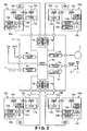
- FIG. 2 is a schematic diagram showing a detailed configuration of the tire air pressure monitoring system of the first embodiment.
- Each of the tire air pressure detecting devices 2 has a pressure sensor 10a (an example of the air pressure detecting unit), a centrifugal switch 10b (an example of the running state detecting unit), an application-specific integrated circuit (ASIC) 10c, a transmitter element 10d, and a transmitting antenna 10e (an example of the transmitting unit).
- ASIC application-specific integrated circuit
- the pressure sensor 10a is configured and arranged to detect the pressure of a corresponding one of the tires 1 and to output it to the ASIC 10c.
- the centrifugal switch 10b is a switch that is open (OFF) when centrifugal force acting upon it is weak, and closed (ON) when centrifugal force acting upon it is strong.
- the centrifugal switch 10b is designed to output an open signal when the vehicle is at a stop (including times of travel at very low speed, e.g. speeds of 5 km/h or less) and to output a closed signal during travel (e.g., in excess of 5 km/h).
- the centrifugal switch 10b is configured and arranged to detect a travel speed (running state) of the vehicle by determining whether the vehicle is traveling in excess of speeds of 5 km/h or not, and from the open/closed signal thereof it can be determined whether the vehicle is traveling (in a high-speed travel state) or at a stop (in a low-speed travel state).
- the centrifugal switch 10b is configured and arranged to output its open/closed signal to the corresponding ASIC 10c.
- the ASIC 10c is an application-specific integrated circuit that is configured to, based on air pressure detected by the pressure sensor 10a and the open/closed signal from the centrifugal switch 10b, generate outgoing data that includes tire air pressure information, to establish a transmitting frequency for the outgoing data, and to output this outgoing data and transmitting frequency to the transmitter element 10d.
- the ASIC 10c will be described in detail later.
- the transmitter element 10d is configured and arranged to transmit the outgoing data from the transmitting antenna 10e according to the transmitting frequency established by the ASIC 10c.
- Each of the antenna-equipped tuners 3 has a receiving antenna 11a for receiving the outgoing data from the tire air pressure detecting device 2, and a tuner 11b constituting the reception circuit.
- the tire air pressure warning controller 4 has a 5V power circuit 4a; a microcomputer 4b that inputs received data from the tuners 11b and that carries out various kinds of data processing thereof; an EEPROM 4c which is a memory from which saved information is electrically erasable, and which is used for ID registration; a display driver circuit 4d for outputting to the display 5 a display driving command to display air pressure information for the tires 1FL, 1FR, 1RL and 1RR based on the received data; a warning lamp output circuit 4e for determining from the received data the pressure values of the installed tires, and outputting a tire air pressure warning command to the low pressure warning lamp 6 in the event of low pressure; an output circuit 4f for outputting to the horn 7 an audible alarm command according to the air pressure during tire inflation; and a display driver circuit 4g for outputting to the turn signals 8 a blinking command according to the air pressure during tire inflation.
- FIG. 3 is a control block diagram of the ASIC 10c in the first embodiment.
- the ASIC 10c preferably includes a microcomputer and other conventional components such as an input interface circuit, an output interface circuit, and memory blocks such as a ROM (Read Only Memory) device and a RAM (Random Access Memory) device.
- the ASIC 10c has an air pressure change rate detecting module (air pressure change rate detecting section) 21 and a frequency adjustment module (frequency adjustment section) 22.
- the air pressure change rate detecting module 21 is configured to detect change per unit time of the air pressure measured by the pressure sensors 10a, i.e., the air pressure change rate.
- the frequency adjustment module 22 is configured to repeatedly execute in a prescribed cycle the control program shown in FIG.
- FIG. 4 is a flowchart depicting the control algorithm for the air pressure transmission control process executed by each of the tire air pressure detecting devices 2 of the tire air pressure monitoring system according to the first embodiment.
- the flowchart of FIG. 4 is initiated by reception of an external trigger signal when the vehicle is shipped from the factory, and is repeated until battery life of a battery provided in the tire air pressure detecting device 2 is exhausted.
- Step S1 the pressure sensor 10a is configured and arranged to measure the air pressure of the corresponding tire 1, and the ASIC 10c is configured to set the measured air pressure as the pressure P1 and to store the pressure P1 in memory. Then, the routine advances to Step S2.
- Step S2 the ASIC 10c is configured to set the pressure P1 stored in memory as the baseline pressure P0, and store the baseline pressure P0 in memory. Then, the routine advances to Step S3.
- Step S3 the ASIC 10c is configured to wait for a prescribed time interval to elapse. After the prescribed time interval has elapsed, the routine proceeds to Step S4.
- the prescribed time interval in step S3 is preferably set to 30 seconds.
- Step S4 the ASIC 10c is configured to monitor the air pressure value. More specifically, in this step, the pressure sensor 10a is configured and arranged to measure the pressure of the corresponding tire 1 again, and the ASIC 10c is configured to set the measured pressure as the pressure P1 and to store the pressure P1 in memory. Then, the routine advances to Step S5.
- Step S5 according to whether the centrifugal switch 10b is ON, the ASIC 10c is configured to determine whether the vehicle has started traveling. If the determination in step S5 is YES, the routine advances to Step S6. If the determination in step S5 is NO, the routine advances to Step S11.
- the ASIC 10c is configured to determine whether an air pressure change rate ⁇ P exceeds a change rate threshold value A.
- the air pressure change rate ⁇ P is obtained as an absolute value of the difference
- the air pressure change rate ⁇ P is obtained by the equation
- the change rate threshold value A is a value that falls within a prescribed pressure fluctuation range during travel, but greater than the change in air pressure predicted to occur during rough road travel.
- the change rate threshold value A is set to 40/30 ⁇ 1.33 kPa/s.
- step S6 determines whether the routine has completed the operation of step S6 or not. If the determination in step S6 is YES, then the routine advances to Step S 12. If the determination in step S6 is NO, the routine advances to Step S7.
- Step S7 the transmission counter is incremented (+1), and the routine advances to Step S8.
- Step S8 the ASIC 10c is configured to determine whether the value of the transmission counter equals a predetermined value N_Drive. If the determination in step S8 is YES, then the routine advances to Step S9. If the determination in step S8 is NO, then the routine returns to Step S2.
- the predetermined value N_Drive is a positive natural number equal to 2 or greater. In the first embodiment, the predetermined value N_Drive is set to 2.
- Step S9 the ASIC 10c is configured to transmit the value of the pressure P1 to the tire air pressure warning controller 4 via the corresponding antenna-equipped tuner 3. Then, the routine proceeds to Step S10.
- eight identical transmission data are preferably transmitted. Given transmission data are transmitted in multiple numbers so that the data will be more reliably received by the antenna-equipped tuner 3.
- Step S10 the ASIC 10c is configured to reset the transmission counter to 0, and then the routine returns to Step S2.
- Step S11 the ASIC 10c is configured to determine whether the air pressure change rate ⁇ P exceeds a change threshold value B.
- the change rate threshold value B is a value that falls within a predetermined pressure fluctuation range when the vehicle is stopped, but is less than the maximum change in air pressure predicted to occur when the user increases the air pressure (when the user inflates the tire). Accordingly, the change rate threshold value B is a smaller value than the change threshold value A.
- the change rate threshold value B is set to 10/30 ⁇ 0.33 kPa/s.
- step S 11 determines whether the determination in step S 11 is YES or not. If the determination in step S 11 is YES, then the routine advances to Step S 12. If the determination in step S11 is NO, then the routine returns to Step S2.
- Step S12 the ASIC 10c is configured to save the current time in memory as the time T0, and then the routine advances to Step S 13.
- Step S 13 the ASIC 10c is configured to transmit the value of pressure P1 to the tire air pressure warning controller 4 via the corresponding antenna-equipped tuner 3. Then, the routine proceeds to Step S 14.
- three identical transmission data are preferably transmitted. Given transmission data are transmitted in multiple numbers so that the data will be more reliably received by the antenna-equipped tuner 3.
- the transmission data is transmitted in step S9 as described above, the tire air pressure is considered to be in a normal state since it has been determined that the air pressure change rate ⁇ P is not greater than the change rate threshold value A in step S6.
- the tire air pressure is considered to be in an abnormal state since it has been determined that the air pressure change rate ⁇ P is greater than the change rate threshold value A in step S6 or that the air pressure change rate ⁇ P is greater than the change rate threshold value B in step S6. Therefore, it is desirable to transmit the tire air pressure data in a real-time manner with a shorter transmitting frequency. Since the transmitting frequency is increased, the number of the identical data transmitted at the same transmission timing in step S13 can be smaller (e.g., 3).
- the actual numbers of the transmitted data in steps S9, S 13 and the corresponding steps in the following embodiments are not limited to the numbers disclosed herein.
- step S6 When the determination in step S6 is YES, it means that the tire pressure might be abnormal.
- step S11 When the determination in step S11 is YES, it means the tire pressure might be abnormal or the tire is being inflated by the user. Therefore, after the transmission data is transmitted to the tire air pressure warning controller 4 in step S 13, the tire air pressure warning controller 4 is configured to illuminate the warning lamp 6 to alert the user that a problem has occurred if the warning lamp 6 has not already been illuminated. If the warning lamp 6 has already been illuminated, that means the tire might be being inflated. Therefore, in such a case, the tire air pressure warning controller 4 is configured to turn off the warning lamp 6 at an appropriate timing (e.g., when the tire air pressure reaches the prescribed correct range of pressure).
- Step S14 the ASIC 10c is configured to wait for a prescribed time interval to elapse. After the prescribed time interval has elapsed, the routine proceeds to Step S 15.
- the prescribed time interval is preferably set to 10 seconds.
- Step S 15 the ASIC 10c is configured to monitor the air pressure value. More specifically, the pressure sensor 10a is configured to measure the air pressure of the tire 1, and the ASIC 10c is configured to set the measured pressure as the pressure P1 and to store the pressure P1 in memory, whereupon the routine then advances to Step S16.
- Step S 16 the ASIC 10c is configured to save the current time in memory as the time T1, and then, the routine advances to Step S17.
- Step S17 the ASIC 10c is configured to determine as to whether the difference between the time T1 that was saved in Step S16 and the time T0 that was saved in Step S12 exceeds a predetermined time period C. If the determination in step S 17 is YES, then the routine advances to RETURN, and the control flow shown in FIG. 4 is repeated. If the determination in step S 17 is NO, then the routine returns to Step S 13.
- the predetermined time period C is preferably set to 30 minutes.
- situations necessitating increased frequency of detecting and transmitting the air pressure include: 1) when the user is increasing the air pressure (when the user is inflating the tire); 2) when a tire puncture or blowout has occurred; and 3) when there has been an appreciable drop in tire air pressure.
- the air pressure change rate observed during inflation of the tire by the user is smaller than the air pressure change rate when a tire puncture or blowout has occurred. That is, because the magnitude of change in air pressure of which the user must be alerted will differ during travel versus when the vehicle is stopped, if a constant non-variable change rate threshold value for switching the transmitting frequency (transmission rate) from low to high with reference to the air pressure change rate is employed, the following trade-offs will occur.
- the change rate threshold value has been set to within the pressure fluctuation range observed with the vehicle stopped in order to increase transmitting frequency during tire inflation, as indicated by the dash-dot line in FIG. 6 , it will frequently occur that the transmitting frequency switches from low to high when the vehicle is traveling due to air pressure fluctuations associated with rough road travel or the like, resulting in unnecessary power consumption by the transmitter.
- the change rate threshold value has been set to within the pressure fluctuation range observed during travel in order to limit unnecessary switching of transmitting frequency, as shown by the solid line in FIG.
- the change rate threshold value A (1.33 kPa/s) during travel is set to be greater than the change rate threshold value B (0.33 kPa/s) with the vehicle stopped.
- the threshold value is variable to be one of the change rate threshold value A and the change rate threshold value B depending on the vehicle running state and the air pressure change rate.
- Step S5 if in Step S5 it is determined that the vehicle is travelling, the system advances to Step S6, whereupon the air pressure change rate ⁇ P and the change rate threshold value A are compared. If ⁇ P ⁇ A, the transmitting frequency remains unchanged at the low frequency of 60-second (30 x 2) intervals (1/60 Hz) (i.e., the prescribed time interval of 30 seconds elapses in step S3 and the routine is repeated twice by the transmission counter in steps S7 and 8).
- the transmitting frequency is switched from the low frequency of 60-second intervals to a high frequency of 10-second intervals (0.1 Hz) (i.e., the prescribed time interval of 10 seconds elapses in step S 14).
- Step S5 it is determined that the vehicle is stopped, the system advances to Step S 11, whereupon the air pressure change rate ⁇ P and the change rate threshold value B ( ⁇ A) are compared. If ⁇ P > B, the transmitting frequency is switched from the low frequency of 60-second intervals to the high frequency of 10-second intervals. On the other hand, if ⁇ P ⁇ B, transmission is suspended.
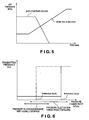
- FIG. 7 is a diagram showing the relationship between air pressure change rate (pressure change) and transmitting frequency in the first embodiment.
- the threshold value for switching the transmitting frequency is set to the change rate threshold value A, and thus, unnecessarily high transmitting frequency due to air pressure fluctuations associated with rough road travel can be avoided.
- the threshold value is set to the change rate threshold value B, and thus, the air pressure detecting accuracy can be increased when the user increases the air pressure (when the user inflates the tire). That is, optimized transmitting frequency according to the vehicle running state (traveling or being stopped) and the air pressure change rate ⁇ P can be achieved, and the required information can be obtained at the lowest transmitting frequency necessary.
- Step S5 if it is determined in Step S5 that the vehicle is stopped, and it is further determined in Step S 11 that ⁇ P ⁇ B, wireless signal transmission is suspended. Specifically, since tire punctures or appreciable drops in air pressure do not normally occur when the vehicle is stopped, if the air pressure change rate ⁇ P is equal to or less than the change rate threshold value B, i.e. if inflation by the user is not detected, transmission of wireless signals can be suspended in order to reduce energy loss with the vehicle at a stop.
- Step S 17 when the predetermined time period C (e.g., 30 minutes) have elapsed in Step S 17 after switching the transmitting frequency from 60-second intervals to 10-second intervals due to a sudden change in air pressure detected in step S6 or S11, transmitting frequency then returns to 60-second intervals. If transmitting frequency were to be maintained at 10-second intervals indefinitely subsequent to a sudden change in the air pressure, the energy loss would be considerable.
- the predetermined time period C e.g. 30 minutes
- the transmitting frequency is switched based on the outcome of comparison of the air pressure change rate ⁇ P with the change rate threshold value A or B. If, for example, the fluctuation range of air pressure (air pressure variation) were to be used instead of the air pressure change rate, if the pressure fluctuation ranges of changes in air pressure due to an increase in the air pressure (or a decrease in the air pressure by a tire puncture) and of changes in air pressure associated with travel or temperature changes happen to be about the same as depicted in FIG. 8 , it will not be possible to distinguish between the two. Consequently, transmitting frequency will frequently become elevated due to travel and temperature changes, resulting in considerable energy losses.
- the fluctuation range of air pressure air pressure variation
- the transmitting frequency is switched based on the air pressure change rate ⁇ P, changes in air pressure due to inflation or a puncture can be distinguished from changes in air pressure associated with travel or temperature changes, so energy losses can be limited.
- the change rate threshold value A is set to a value (1.33 kPa/s) that is greater than the maximum air pressure change rate predicted to occur during rough road travel; and when the vehicle is stopped the change rate threshold value B is set to a value (0.33 kPa/s) that is smaller than the predicted air pressure change rate when the user increases the air pressure.
- the air pressure change rate during rough road travel is sometimes higher than the air pressure change rate during tire inflation.
- the transmitting frequency can be increased while inflation is taking place, so that the user may be frequently notified of the air pressure.
- the air pressure detecting frequency (30-second intervals as counted in step S3) is shorter than the transmitting frequency (60-second intervals). This is because if the detecting frequency were matched with the transmitting frequency (60-second intervals), performance would be degraded due to delayed timing of detecting the air pressure; whereas if, conversely, the transmitting frequency were matched with the detecting frequency (30-second intervals), there would be considerable energy loss. That is, by making the detecting frequency shorter than the transmitting frequency, it is possible to both minimize energy losses and ensure good performance.
- the detecting frequency and the transmitting frequency are both brought into synchronization at 10-second intervals, thus avoiding energy losses resulting from mismatched timing of the detecting frequency and the transmitting frequency.
- the tire air pressure monitoring system of the first embodiment affords the following exemplary effects.
- the actual values (intervals) of the transmitting frequency and detecting frequency in the first embodiment and the following embodiments are not limited to the values disclosed herein.
- the transmitting frequency and detecting frequency can be changed by appropriately setting the prescribed intervals used in steps S3 and S14, and the predetermined value N-Drive (counter) used in step S8.
- FIGS. 10 to 12 a tire air pressure detecting device, a tire air pressure monitoring system, and a tire air pressure notification method in accordance with a second embodiment will now be explained.
- the parts of the second embodiment that are identical to the parts of the first embodiment will be given the same reference numerals as the parts of the first embodiment.
- the descriptions of the parts of the second embodiment that are identical to the parts of the first embodiment may be omitted for the sake of brevity.
- the tire air pressure monitoring system of the second embodiment differs from the tire air pressure monitoring system of the first embodiment in that the detecting frequency and the transmitting frequency of the tire air pressure when the vehicle is at a stop can be set to shorter (higher) frequencies than the detecting frequency and the transmitting frequency when the vehicle is traveling.
- the physical structures of the tire air pressure monitoring system of the second embodiment is identical to the physical structures of the tire air pressure monitoring system of the first embodiment as illustrated in FIGS. 1 to 3 , and thus, the description thereof is omitted for the sake of brevity.
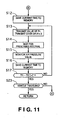
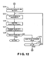
- FIGS. 10 , 11 , and 12 depict the control algorithm executed by each of the tire air pressure detecting devices 2 in the second embodiment. Steps for carrying out processes identical to those of the first embodiment depicted in FIG. 4 have been assigned like step symbols and are not described.
- Step S21 shown in FIG. 10 according to whether the centrifugal switch 10b is OFF, the ASIC 10c is configured to determine whether the vehicle is stopped. If the determination in step S21 is YES, then the routine advances to Step S24 shown in FIG. 12 . If the determination in step S21 is NO, the routine advances to Step S22.
- Step S22 the pressure sensor 10a is configured and arranged to measure the air pressure of the tire 1, and the ASIC 10c is configured to set the measured pressure as the pressure P1 and to store the pressure P1 in memory. Then, the routine advances to Step S6.
- Step S23 shown in FIG. 11 according to whether the centrifugal switch 10b is ON, the ASIC 10c is configured to determine whether the vehicle is being driven. If the determination in step S23 is YES, then the routine advances to RETURN and the control flow depicted in FIGS. 10 to 12 is repeated. If the determination in step S23 is NO, then the routine advances to Step S24 shown in FIG. 12 .
- Step S24 the pressure sensor 10a is configured and arranged to measure the air pressure of the tire 1, and the ASIC 10c is configured to set the measured pressure as the pressure P1 and to store the pressure P1 in memory. Then, the routine advances to Step S25.
- Step S25 the ASIC 10c is configured to set the pressure P1 in memory as the baseline pressure P0, and to store the baseline pressure P0 in memory. Then, the routine advances to Step S26.
- Step S26 the ASIC 10c is configured to wait for a prescribed time interval to elapse. After the prescribed time interval has elapsed, the routine proceeds to Step S27.
- the prescribed time interval is preferably set to 15 seconds.
- Step S27 the ASIC 10c is configured to transmit the value of pressure P1 to the tire air pressure warning controller 4 via the corresponding antenna-equipped tuner 3. Then, the routine proceeds to Step S28.
- three identical transmission data are preferably transmitted.
- Step S28 according to whether the centrifugal switch 10b is ON, the ASIC 10c is configured to determine whether the vehicle has started to travel (i.e., whether the vehicle is traveling). If the determination in step S28 is YES, then the routine advances to RETURN and the control flow depicted in FIGS. 10 to 12 is repeated. If the determination in step S28 is NO, then the routine advances to Step S29.
- Step S29 the pressure sensor 10a is configured and arranged to measure the air pressure of the tire 1, and the ASIC 10c is configured to set the measured pressure as the pressure P1 and to store the pressure P1 in memory. Then, the routine advances to Step S30.
- Step S30 a determination is made as to whether the air pressure change rate ⁇ P is greater than the change rate threshold value B.
- the air pressure change rate ⁇ P is obtained as an absolute value of the difference
- the change rate threshold value B used in step S30 is the same as the change rate threshold value B used in step S11 of the first embodiment. If the determination in step S30 is YES, then the routine advances to Step S12 shown in FIG. 11 . If the determination in step S30 is NO, then the routine returns to Step S25.
- step S30 When the determination in step S30 is YES, it means the tire pressure might be abnormal or the tire might be being inflated by the user. Therefore, after the transmission data is transmitted to the tire air pressure warning controller 4 in step S 13, the tire air pressure warning controller 4 is configured to illuminate the warning lamp 6 to alert the user that a problem has occurred if the warning lamp 6 has not already been illuminated. If the warning lamp 6 has already been illuminated, that means the tire might be being inflated. Therefore, in such a case, the tire air pressure warning controller 4 is configured to turn off the warning lamp 6 at an appropriate timing (e.g., when the tire air pressure reaches the prescribed correct range of pressure).
- Step S2 during travel, when the air pressure change rate ⁇ P is equal to or less than the change rate threshold value A, the flow repeatedly advances through Step S2 ⁇ Step S3 ⁇ Step S21 ⁇ Step S22 ⁇ Step S6 ⁇ Step S7 ⁇ Step S8 ⁇ Step S9 ⁇ Step S10, and the air pressure detecting frequency is set to 30 seconds (in step S3) while the transmitting frequency is set to 60-seconds (30 x 2) as in the first embodiment.
- Step S12 During travel, when the air pressure change rate ⁇ P exceeds the change rate threshold value A, the flow repeatedly advances through Step S12 ⁇ Step S13 ⁇ Step S14 ⁇ Step 15 ⁇ Step S16 ⁇ Step S 17, and the tire air pressure detecting frequency and the transmitting frequency are both set to 10-second intervals until the predetermined time period C (e.g., 30 minutes) has passed as in the first embodiment.
- the predetermined time period C e.g. 30 minutes
- Step S25 when the air pressure change rate ⁇ P is equal to or less than the change rate threshold value B, the flow repeatedly advances through Step S25 ⁇ Step S26 ⁇ Step S27 ⁇ Step S28 ⁇ Step S29 ⁇ Step S30, and the tire air pressure detecting frequency and the transmitting frequency are both set to 15-second intervals (1/15 Hz).
- the tire air pressure detecting frequency and the transmitting frequency are both set to 10-second intervals until the predetermined time period C (e.g., 30 minutes) has passed, in the same manner as during travel.
- Steps S22, S6 to S10 and Steps S12 to S23 a process taking place with the vehicle stopped
- Steps S24 to S29 a process taking place with the vehicle stopped
- a 30-second interval for detecting frequency and a 60-second interval for transmitting frequency are established during travel when the air pressure change rate ⁇ P is equal to or less than the change rate threshold value A
- a 15-second interval for both detecting frequency and transmitting frequency is established with the vehicle stopped when the air pressure change rate ⁇ P is equal to or less than the change rate threshold value B.
- the purpose of detecting the air pressure change rate differs during travel versus when the vehicle is at a stop.
- the aim is to notify the user if a puncture occurs, whereas with the vehicle at a stop it is to notify the user of changing air pressure occurring with inflation.
- inflation it is preferable for the user to be presented more promptly with the outcome of the inflation.
- the tire air pressure monitoring system of the second embodiment affords the following effect in addition to effects (1) to (5) and (7) to (9) of the first embodiment.
- the frequency adjustment modules 22 set the transmitting frequency (15-second intervals) when the air pressure change rate ⁇ P is equal to or less than the change rate threshold value B when the vehicle is stopped to a higher frequency than the transmitting frequency (60-second intervals) when the air pressure change rate ⁇ P is equal to or less than the change rate threshold value A during travel, the user can be more promptly notified of air pressure when carrying out inflation with the vehicle stopped.
- Step S27 in FIG. 12 may be omitted so that transmission is suspended when the vehicle is stopped and when the air pressure change rate ⁇ P is equal to or less than the change rate threshold value B as in the first embodiment. In such a case, energy loss while the vehicle is stopped can be reduced by suspending transmission of the transmission data.
- FIGS. 10 and 13-17 a tire air pressure detecting device, a tire air pressure monitoring system, and a tire air pressure notification method in accordance with a third embodiment will now be explained.
- the parts of the third embodiment that are identical to the parts of the first or second embodiment will be given the same reference numerals as the parts of the first or second embodiment.
- the descriptions of the parts of the third embodiment that are identical to the parts of the first or second embodiment may be omitted for the sake of brevity.
- the third embodiment differs from the second embodiment in that the period of time, over which the higher transmitting frequency is maintained after a sudden pressure change has occurred, differs during travel versus when the vehicle is stopped in the third embodiment.
- the physical structures of the tire air pressure monitoring system of the third embodiment is identical to the physical structures of the tire air pressure monitoring system of the first embodiment as illustrated in FIGS. 1 to 3 , and thus, the description thereof is omitted for the sake of brevity.
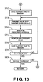
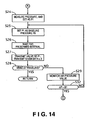
- FIGS. 10 , 13 , 14 , and 15 depict the control algorithm executed by each of the tire air pressure detecting devices 2 in the third embodiment. Only those portions that differ from the second embodiment are described.
- Step S31 shown in FIG. 13 the ASIC 10c is configured to determine whether the difference between the time T1 that was saved in Step S16 and the time T0 that was saved in Step S12 exceeds a predetermined time period C1 (e.g., 5 minutes). If the determination in step S31 is YES, then the routine advances to Step S23. If the determination in step S31 is NO, then the routine returns to Step S13.
- a predetermined time period C1 e.g., 5 minutes
- Step S32 shown in FIG. 14 the ASIC 10c is configured to determine whether the air pressure change rate ⁇ P exceeds the change rate threshold value B.
- the air pressure change rate ⁇ P is obtained as an absolute value of the difference
- the air pressure change rate ⁇ P is obtained by the equation
- the change rate threshold value B used in step S32 is the same as the change rate threshold value B used in step S11 of the first embodiment. If the determination in step S32 is YES, then the routine advances to Step S33 shown in FIG. 15 . If the determination in step S32 is NO, the routine returns to Step S25.
- step S32 When the determination in step S32 is YES, it means the tire air pressure might be abnormal or the tire might be being inflated by the user. Therefore, after the transmission data is transmitted to the tire air pressure warning controller 4 in step S34 (described later), the tire air pressure warning controller 4 is configured to illuminate the warning lamp 6 to alert the user that a problem has occurred if the warning lamp 6 has not already been illuminated. If the warning lamp 6 has already been illuminated, that means the tire might be being inflated. Therefore, in such a case, the tire air pressure warning controller 4 is configured to turn off the warning lamp 6 at an appropriate timing (e.g., when the tire air pressure reaches the prescribed correct range of pressure).
- the warning lamp 6 will be extinguished when air pressure that is acquired after the next time that the ignition switch is turned ON has exceeded a threshold value for extinguishing the warning lamp 6.
- Step S33 shown in FIG. 15 the ASIC 10c is configured to save the current time in memory as T0, and then, the routine advances to Step S34.
- Step S34 the ASIC 10c is configured to transmit the value of pressure P1 to the tire air pressure warning controller 4 via the corresponding antenna-equipped tuner 3. Then, the routine proceeds to Step S35.
- three identical transmission data are preferably transmitted. Given transmission data are transmitted in multiple numbers so that the data will be more reliably received by the antenna-equipped tuner 3.
- Step S35 the ASIC 10c is configured to wait for a prescribed time interval to elapse. After the prescribed time interval has elapsed, the routine proceeds to Step S36.
- the prescribed time interval is preferably set to 10 seconds.
- Step S36 the ASIC 10c is configured to monitor the air pressure value. More specifically, the pressure sensor 10a is configured to measure the air pressure of the tire 1, and the ASIC 10c is configured to set the measured pressure as the pressure P1 and to store the pressure P1 in memory, whereupon the routine then advances to Step S37.
- Step S37 the ASIC 10c is configured to save the current time in memory as the time T1, and then, the routine advances to Step S38.
- Step S38 the ASIC 10c is configured to determine as to whether the difference between the time T1 that was saved in Step S37 and the time T0 that was saved in Step S33 exceeds a predetermined time period C2 (30 min). If the determination in step S38 is YES, then the routine advances to Step S39. If the determination in step S38 is NO, then the routine advances to Step S34.
- Step S39 according to whether the centrifugal switch 10b is ON, the ASIC 10c is configured to determine whether the vehicle is being driven. If the determination in step S39 is YES, then the routine advances to RETURN and the control flow depicted in FIGS. 10 , 13 , 14 and 15 is repeated. If the determination in step S39 is NO, then the routine advances to Step S24 shown in FIG. 14 .
- the transmitting frequency switches from 60-second (30 x 2) intervals to 10-second intervals. Subsequently after the prescribed time period C1 (e.g., 5 minutes) have passed, the transmitting frequency returns from 10-second intervals to 60-second intervals.
- the prescribed time period C1 e.g., 5 minutes
- FIG. 16 is a timing chart showing air pressure and transmitting frequency when a tire puncture occurs.
- the warning lamp 6 can be illuminated immediately to warn the user of that a tire puncture has occurred, regardless of whether the user has brought the vehicle to a stop as shown in FIG. 16 or continues to drive after the tire puncture. That is, when a puncture occurs, it is not necessary for high transmitting frequency to be maintained for an extended period.
- a shorter time period C1 e.g., 5 minutes
- the transmitting frequency with the vehicle stopped is shorter, i.e. 15-second intervals, than the transmitting frequency of 60-second interval during travel.
- the transmitting frequency when with vehicle stopped switches from 15-second interval to 10-second intervals.
- the transmitting frequency returns from 10-second intervals to 15-second interval.
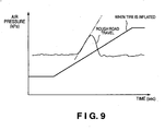
- FIG. 17 (a) is a timing chart illustrating air pressure and transmitting frequency during tire inflation and a command signal transmitted to a warning lamp when the user inflates the tire while the ignition switch is ON.
- the warning lamp Prior to this time chart shown in FIG. 17 (a) takes place, the warning lamp is turned on by detecting a drop in a tire air pressure during travel due to a tire puncture or the like as shown in FIG. 16 . Then, according to the third embodiment, if the ignition switch is maintained ON while the user subsequently inflates the tire, the warning lamp 6 is extinguished when it is detected that the air pressure exceeds a turn-off threshold value for extinguishing the warning lamp 6 as shown in FIG. 17 (a) .
- the tire air pressure warning controller 4 cannot notify the user of the air pressure transmitted by the tire air pressure detecting devices 2. More specifically, if the ignition switch is turned OFF after the warning lamp is turned on by detecting a drop in tire air pressure during travel due to a tire puncture or the like, the functioning of the tire air pressure warning controller 4 will be interrupted in a condition in which it is still outputting a lamp light-up command. Thus, if the user has carried out tire inflation with the ignition switch being turned OFF as shown in FIG.
- the warning lamp 6 will remain illuminated in response to the lamp light-up command when the ignition switch is next turned ON, despite the air pressure being in the proper range.
- the air pressure acquired by the air pressure warning controller 4 immediately after the ignition switch is turned ON will have a value above the turn-off threshold value. Therefore, according to the third embodiment, by maintaining the increased transmitting frequency (e.g., 10-second interval) for an extended period of time (e.g., 30 minutes) when the sudden pressure change is detected while the vehicle is stopped, the warning lamp 6 can be extinguished relatively quickly after the ignition switch is turned ON as shown in FIG. 17 (b) , if the ignition switch is turned ON within the extended period of time (e.g., 30 minutes).
- the time needed for the user to carry out the inflation procedure is uncertain, by establishing an extended period (e.g., 30 minutes) for increased transmitting frequency, even if the user has carried out tire inflation with the ignition switch OFF, the user can be promptly notified of the air pressure the next time that the ignition switch is turned ON.
- an extended period e.g., 30 minutes
- the tire air pressure monitoring system of the third embodiment affords the following effect in addition to effects (1) to (5) and (7) to (9) of the first embodiment and effect (10) of the second embodiment.
- Step S27 in FIG. 14 may be omitted so that transmission is suspended when the vehicle is stopped and when the air pressure change rate ⁇ P is equal to or less than the change rate threshold value B or D as in the first embodiment. In such a case, energy loss while the vehicle is stopped can be reduced by suspending transmission of the transmission data.
- FIGS. 10 and 18 to 21 a tire air pressure detecting device, a tire air pressure monitoring system, and a tire air pressure notification method in accordance with a fourth embodiment will now be explained.
- the parts of the fourth embodiment that are identical to the parts of the previous embodiments will be given the same reference numerals as the parts of the previous embodiments.
- the descriptions of the parts of the fourth embodiment that are identical to the parts of the previous embodiments may be omitted for the sake of brevity.
- the forth embodiment differs from the third embodiment in that the change rate threshold value used before a prescribed time period has elapsed after stopping the vehicle is different from the change rate threshold value used after the prescribed time period has elapsed after stopping the vehicle.
- the physical structures of the tire air pressure monitoring system of the fourth embodiment is identical to the physical structures of the tire air pressure monitoring system of the first embodiment as illustrated in FIGS. 1 to 3 , and thus, the description thereof is omitted for the sake of brevity.
- FIGS. 10 , 15 , 18 , 19 , and 20 depict the control algorithm executed by each of the tire air pressure detecting devices 2 in the fourth embodiment. Only those portions that differ from the third embodiment are described.
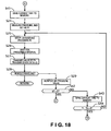
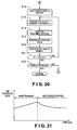
- Step S41 shown in FIG. 18 the ASIC 10c is configured to save the current time in memory as the time T0, and then the routine advances to Step S24.
- Step S42 shown in FIG. 18 the ASIC 10c is configured to determine whether the air pressure change rate ⁇ P exceeds a predetermined change rate threshold value D.
- the change rate threshold value D is a value greater than the change rate threshold value B.
- the change rate threshold value D is 14/15 ⁇ 0.93 kPa/s.
- the air pressure change rate ⁇ P is obtained as an absolute value of the difference
- Step S43 the ASIC 10c is configured to save the current time in memory as the time T1, and then the routine advances to Step S44.
- Step S44 the ASIC 10c is configured to determine whether the difference between the time T1 that was saved in Step S43 and the time T0 that was saved in Step S41 exceeds a predetermined time period E. If the determination in step S44 is YES, then the routine advances to Step S45 shown in FIG. 19 . If the determination in step S44 is NO, then the routine returns to Step S25.
- the predetermined time period E is preferably set to 60 minutes.
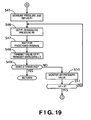
- Step S45 shown in FIG. 10 the pressure sensor 10a is configured and arranged to measure the air pressure of the corresponding tire 1, and the ASIC 10c is configured to set the measured air pressure as the pressure P1 and to store the pressure P1 in memory. Then, the routine advances to Step S46.
- Step S46 the ASIC 10c is configured to set the pressure P1 stored in memory as the baseline pressure P0, and store the baseline pressure P0 in memory. Then, the routine advances to Step S47.
- Step S47 the ASIC 10c is configured to wait for a prescribed time interval to elapse. After the prescribed time interval has elapsed, the routine proceeds to Step S48.
- the prescribed time interval in step S47 is preferably set to 15 seconds.
- step S48 the ASIC 10c is configured to transmit the value of pressure P1 to the tire air pressure warning controller 4 via the corresponding antenna-equipped tuner 3. Then, the routine proceeds to Step S49.
- three identical transmission data are preferably transmitted.
- Step S49 according to whether the centrifugal switch 10b is ON, the ASIC 10c is configured to determine whether the vehicle is traveling. If the determination in step S49 is YES, then the routine advances to RETURN, and the control flow depicted in FIGS. 10 , 15 , 18 , 19 and 20 is repeated. If the determination in step S49 is NO, then the routine advances to Step S50.
- Step S50 the ASIC 10c is configured to monitor the air pressure value. More specifically, in this step, the pressure sensor 10a is configured and arranged to measure the pressure of the corresponding tire 1 again, and the ASIC 10c is configured to set the measured pressure as the pressure P1 and to store the pressure P1 in memory. Then, the routine advances to Step S51.
- Step S51 the ASIC 10c is configured to determine whether the air pressure change rate ⁇ P exceeds the change rate threshold value B.
- the air pressure change rate ⁇ P is obtained as an absolute value of the difference
- the change rate threshold value B used in step S51 is the same as the change rate threshold value B used in step S 11 of the first embodiment. If the determination in step S51 is YES, then the routine advances to Step S33 shown in FIG. 15 . If the determination in step S51 is NO, then the routine returns to Step S46.
- Step S51 the tire air pressure warning controller 4 illuminates the warning lamp 6 to alert the user that a problem has occurred.
- the tire air pressure warning controller 4 is configured to illuminate the warning lamp 6 to alert the user that a problem has occurred if the warning lamp 6 has not already been illuminated. If the warning lamp 6 has already been illuminated, that means the tire might be being inflated. Therefore, in such a case, the tire air pressure warning controller 4 is configured to turn off the warning lamp 6 at an appropriate timing (e.g., when the tire air pressure reaches the prescribed correct range of pressure).
- the change rate threshold value for comparison with the air pressure change rate ⁇ P is D (0.93 kPa/s) (Step S42). Thereafter, once the predetermined time period E has elapsed, the change rate threshold value switches from D to B (0.33 kPa/s) (Step S51).
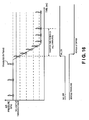
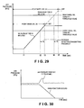
- FIG. 21 is a timing chart showing change in air pressure after the vehicle has stopped. For some time after the vehicle is stopped, tire air pressure changes in such a way that the air pressure drops by the equivalent of the increase due to temperature change during travel, and subsequently settles down to a value depending on ambient temperature.
- the change rate threshold value were switched to B (0.33 kPa/s), which lies within the pressure fluctuation range with the vehicle at a stop and which is smaller than the maximum predicted value for air pressure change rate when the user increases the air pressure, there would be a risk that the air pressure change rate ⁇ P resulting from the drop in air pressure will exceed the change rate threshold value B, and that a false alert of abnormal air pressure will be issued.
- B 0.33 kPa/s
- the change rate threshold value D employed until the predetermined time period E has elapsed after stopping the vehicle is a greater value than the change rate threshold value B.
- Adopting a smaller value for the change rate threshold value D than for the change rate threshold value B affords the following advantage.
- inflation performed by the user takes place within a prescribed time period after the vehicle has stopped at a gas station or the like.
- the change rate threshold value D e.g. to 4/15 ⁇ 0.27 kPa/s
- alerts can be issued more dependably during tire inflation.
- the tire air pressure monitoring system of the fourth embodiment affords the following effect in addition to effects (1) to (5) and (7) to (9) of the first embodiment, the effect (10) of the second embodiment and the effect (11) of the third embodiment.
- the frequency adjustment modules 22 specify the change rate threshold value D different from the change rate threshold value B that is specified after the end of the predetermined time period E.
- the change rate threshold value D is greater than the change rate threshold value B, false alerts associated with change in air pressure occurring after the vehicle first comes to a stop can be avoided. If the threshold value D is smaller than the change rate threshold value B, alerts can be issued more dependably during tire inflation.
- Step S27 in FIG. 18 and Step S48 in FIG. 19 may be omitted so that transmission is suspended when the vehicle is stopped and when the air pressure change rate ⁇ P is equal to or less than the change rate threshold value B or D as in the first embodiment. In such a case, energy loss while the vehicle is stopped can be reduced by suspending transmission of the transmission data.
- FIGS. 4 and 22 a tire air pressure detecting device, a tire air pressure monitoring system, and a tire air pressure notification method in accordance with a fifth embodiment will now be explained.
- the parts of the fifth embodiment that are identical to the parts of the previous embodiments will be given the same reference numerals as the parts of the previous embodiments.
- the descriptions of the parts of the fifth embodiment that are identical to the parts of the previous embodiments may be omitted for the sake of brevity.
- the fifth embodiment differs from the first embodiment as described above in the control executed in step S 11 of FIG. 4 . More specifically, in the fifth embodiment, the air pressure change rate threshold value B after the vehicle first comes to a stop is small, and the air pressure change rate threshold value B increases with the passage of time.
- the physical structures of the tire air pressure monitoring system of the fifth embodiment is identical to the physical structures of the tire air pressure monitoring system of the first embodiment as illustrated in FIGS. 1 to 3 , and thus, the description thereof is omitted for the sake of brevity.
- control algorithm executed by each of the tire air pressure detecting devices 2 in the fifth embodiment is substantially identical to the first embodiment depicted in FIG. 4 except that the specifics of Step S11 have been modified as follows.
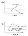
- a corrected change rate threshold value B' is calculated by subtracting from the change rate threshold value B a change rate threshold value correction quantity ⁇ B according to elapsed time starting after the vehicle is first stopped.
- the characteristic of the change rate threshold value correction quantity ⁇ B with respect to the passage of time is such that, in response to the tire temperature drop observed just after travel stops, it progressively decreases in magnitude as time passes, and ultimately converges to zero. This characteristic is derived beforehand empirically with reference to tire volume, size and so on, and saved in memory.
- tire air pressure changes in such a way that the air pressure drops by the equivalent of the increase due to temperature change during travel.
- this drop in air pressure will be reflected in the air pressure change rate, with the detected air pressure change rate being smaller in relation to the inflation level the shorter the elapsed time since the vehicle was stopped. Consequently, where the change rate threshold value is constant, soon after the vehicle is first stopped the likelihood that the air pressure change rate exceeds the change rate threshold value will be low, so the frequency of both detecting and transmission of air pressure will fail to increase.
- the change rate threshold value B' is small when the vehicle has first stopped and progressively increases thereafter with the passage of time, even if the user happens to carry out the inflation operation soon after the vehicle has stopped, it will be possible to mitigate the effects of stopping on the change in air pressure, and the frequency of detecting and transmission of air pressure can be increased during tire inflation.
- the tire air pressure monitoring system of the fifth embodiment affords the following effect in addition to effects (1) to (9) of the first embodiment, the effect (10) of the second embodiment and the effect (11) of the third embodiment.
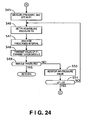
- FIGS. 10 , 15 , 20 , 23 and 24 a tire air pressure detecting device, a tire air pressure monitoring system, and a tire air pressure notification method in accordance with a sixth embodiment will now be explained.
- the parts of the sixth embodiment that are identical to the parts of the previous embodiments will be given the same reference numerals as the parts of the previous embodiments.
- the descriptions of the parts of the sixth embodiment that are identical to the parts of the previous embodiments may be omitted for the sake of brevity.
- the sixth embodiment differs from the fourth embodiment in that, in sixth embodiment, the detecting frequency for a prescribed time period after the vehicle first stops is higher than the detecting frequency after the prescribed time period elapses.
- the physical structures of the tire air pressure monitoring system of the sixth embodiment is identical to the physical structures of the tire air pressure monitoring system of the first embodiment as illustrated in FIGS. 1 to 3 , and thus, the description thereof is omitted for the sake of brevity.
- FIGS. 10 , 15 , 20 , 23 , and 24 depict the control algorithm executed by each of the tire air pressure detecting devices 2 in the sixth embodiment. Only the portion of the control program executed by the ASIC 10c of the tire air pressure detecting device 2 in the sixth embodiment that differs from the fourth embodiment will be described.
- Step S52 shown in FIG. 23 the ASIC 10c is configured to wait for a prescribed time interval to elapse. After the prescribed time interval has elapsed, the routine proceeds to Step S28.
- the prescribed time interval is preferably set to 5 seconds.
- Step S53 shown in FIG. 23 the ASIC 10c is configured to determine whether the air pressure change rate ⁇ P exceeds the predetermined change rate threshold value D.
- the change rate threshold value D is the same as the value used in step S42 of FIG. 18 in the fourth embodiment.
- the air pressure change rate ⁇ P is obtained as an absolute value of the difference
- Step S54 shown in FIG. 24 the ASIC 10c is configured to determine whether the air pressure change rate ⁇ P exceeds the predetermined change rate threshold value D.
- the air pressure change rate ⁇ P is obtained as an absolute value of the difference
- the detecting frequency is set to 5-second intervals (Step S52) until the end of a fixed time period E (Step S44), and thereafter when the fixed time period E has ended, the detecting frequency is switched from 5 seconds to 15 seconds (Step S47).
- inflation by the user takes place within a fixed time period after the vehicle has stopped at a gas station or the like.
- the user can be more promptly notified of the inflation results when the air pressure change rate ⁇ P exceeds the change rate threshold value D, that is, when the user begins to increase the air pressure.
- the period of increased detecting frequency to the fixed time period E (e.g., 60 minutes), energy losses can be reduced.
- the tire air pressure monitoring system of the sixth embodiment affords the following effect in addition to effects (1) to (5) and (7) to (9) of the first embodiment, the effect (10) of the second embodiment, the effect (11) of the third embodiment, and the effect (12) of the fourth embodiment.
- the frequency adjustment modules 22 increase the detecting frequency (5-second intervals) of the pressure sensors 10a to a level higher than the detecting frequency (15-second intervals) after the prescribed time interval E ends, the user can be more promptly notified of the inflation results, and energy losses can be reduced.
- Step S27 in FIG. 23 and Step S48 in FIG. 24 may be omitted so that transmission is suspended when the vehicle is stopped and when the air pressure change rate ⁇ P is equal to or less than the change rate threshold value D as in the first embodiment. In such a case, energy loss while the vehicle is stopped can be reduced by suspending transmission of the transmission data.
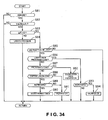
- FIGS. 25 to 29 a tire air pressure detecting device, a tire air pressure monitoring system, and a tire air pressure notification method in accordance with a seventh embodiment will now be explained.
- the parts of the seventh embodiment that are identical to the parts of the previous embodiments will be given the same reference numerals as the parts of the previous embodiments.
- the descriptions of the parts of the seventh embodiment that are identical to the parts of the previous embodiments may be omitted for the sake of brevity.
- the seventh embodiment differs from the second embodiment in that, in the seventh embodiment, the transmitting frequency is increased when the previous value and the current value of air pressure traverse a prescribed air pressure threshold value (a predetermined display content changeover threshold value) for user notification, in other words, when the prescribed air pressure threshold value falls between the previous value and the current value of air pressure.
- a prescribed air pressure threshold value a predetermined display content changeover threshold value
- the physical structures of the tire air pressure monitoring system of the seventh embodiment is identical to the physical structures of the tire air pressure monitoring system of the first embodiment as illustrated in FIGS. 1 to 3 , and thus, the description thereof is omitted for the sake of brevity.
- FIGS. 25 , 26 , and 27 depict the control algorithm executed by each of the tire air pressure detecting devices 2 in the seventh embodiment. Only the portion of the control program executed by the ASIC 10c of the tire air pressure detecting device 2 in the seventh embodiment that differs from the second embodiment will be explained.
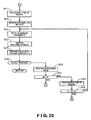
- Step S60 shown in FIG. 25 the ASIC 10c is configured to transmit the pressure P1 that was set in Step S22 to the tire air pressure warning controller 4. Then, the routine then advances to Step S 10.
- Step S61 the ASIC 10c is configured to save the current time in memory as T0, and then the routine advances to Step S62.
- Step S62 the ASIC 10c is configured to determine whether the pressure P1 set in Step S22 and the baseline pressure P0 set in Step S20 traverse a prescribed air pressure threshold value (a lamp light-up threshold value or a lamp turn-off threshold value), in other words, when the prescribed air pressure threshold value falls between the pressure P1 and the baseline pressure P0. If the determination in step S62 is YES, then the routine advances to Step S63. If the determination in step S62 is NO, then the routine advances to Step S78.
- the lamp light-up threshold value and the lamp turn-off threshold value may have the same value; or the system may be designed to exhibit hysteresis in order to prevent hunting.
- the lamp light-up threshold value and the lamp turn-off threshold value are saved in memory in the ASIC 10c beforehand.
- Step S63 the ASIC 10c is configured to wait a prescribed time interval to elapse. After the prescribed time interval has elapsed, the routine proceeds to Step S64.
- the prescribed time interval is preferably set to 10 seconds.
- Step S64 according to whether the centrifugal switch 10b is OFF, the ASIC 10c is configured to determine whether the vehicle is stopped. If the determination in step S64 is YES, then the routine advances to Step S24. If the determination in step S64 is NO, then the routine advances to Step S65.
- Step S65 the pressure sensor 10a is configured to measure the air pressure of the tire 1, and the ASIC 10c is configured to set the measured pressure as the pressure P2 and to store the pressure P2 in memory. Then, the routine advances to Step S66.
- Step S66 the ASIC 10c is configured to determine whether the pressure P2 set in Step S65 and the baseline pressure P0 set in Step S2 traverse the prescribed air pressure threshold value. If the determinant in step S66 is YES, then the routine advances to Step S67. If the determination in step S66 is NO, then the routine advances to Step S78.
- Step S67 the ASIC 10c is configured to increment the transmission counter (+1), and then the routine advances to Step S68.
- Step S68 the ASIC 10c is configured to determine whether the value of the transmission counter equals a predetermined value N_Drive.
- the predetermined value N_Drive is preferably set to 6. If the determination in step S68 is YES, then the routine advances to Step S69. If the determination in step S68 is NO, then the routine advances to Step S63. Therefore, when the pressure P1 set in Step S22 and the baseline pressure P0 set in Step S20 do not traverse a prescribed air pressure threshold value in step S62 and when the pressure P2 set in Step S65 and the baseline pressure P0 set in Step S2 do not traverse the prescribed air pressure threshold value, the transmitting frequency is set to 60-second (10 x 6) intervals by repeating the steps S63-S67.
- Step S69 the ASIC 10c is configured to transmit the value of the pressure P1 to the tire air pressure warning controller 4, and then the routine advances to Step S70.
- eight identical transmission data are preferably transmitted. Given transmission data are transmitted in multiple numbers so that the data will be more reliably received by the antenna-equipped tuner 3.
- Step S70 the ASIC 10c is configured to reset the transmission counter to zero, and then the routine advances to Step S63.
- Step S71 shown in FIG. 26 the ASIC 10c is configured to save the current time in memory as T0, and then the routine advances to Step S72.
- Step S72 the ASIC 10c is configured to determine whether the pressure P1 set in Step S24 and the baseline pressure P0 set in Step S25 traverse the prescribed air pressure threshold value. If the determination in step S72 is YES, then the routine advances to Step S73. If the determination in step S72 is NO, then the routine advances to Step S78.
- Step S73 the ASIC 10c is configured to wait for a prescribed time interval to elapse. After the prescribed time interval has elapsed, the routine proceeds to Step S74.
- the prescribed time interval is preferably set to 15 seconds.
- step S74 the ASIC 10c is configured to transmit the value of pressure P1 to the tire air pressure warning controller 4 via the corresponding antenna-equipped tuner 3. Then, the routine proceeds to Step S75.
- three identical transmission data are preferably transmitted.
- Step S75 according to whether the centrifugal switch 10b is ON, the ASIC 10c is configured to determine whether the vehicle has started traveling. If the determination in step S75 is YES, then the routine advances to RETURN and the control flow depicted in FIGS. 25 , 26 and 27 is repeated. If the determination in step S75 is NO, then the routine advances to Step S76.
- Step S76 the pressure sensor 10a is configured to measure the air pressure, and the ASIC 10c is configured to set the measured pressure as the pressure P2 and to store the pressure P2 in memory. Then, the routine advances to Step S77.
- Step S77 the ASIC 10c is configured to determine whether the pressure P2 set in Step S76 and the baseline pressure P0 set in Step S25 traverse a prescribed air pressure threshold value. If the determination in step S77 is YES, then the routine advances to Step S73. If the determination in step S77 is NO, then the routine advances to Step S78.
- Step S78 the ASIC 10c is configured to transmit the latest pressure value (P1 or P2) to the tire air pressure warning controller 4.
- the latest pressure value P1 or P2
- three identical transmission data are preferably transmitted. Given transmission data are transmitted in multiple numbers so that the data will be more reliably received by the antenna-equipped tuner 3.
- the detecting frequency is switched from 30-second intervals to 10-second intervals during travel and from 15-second intervals to 10-second intervals with the vehicle stopped.
- the transmitting frequency is switched from 60-second intervals to 10-second intervals during travel and from no-transmission to 10-second intervals with the vehicle stopped (Step S 14).
- the tire air pressure warning controller 4 When air pressure falls below the lamp light-up threshold value, the tire air pressure warning controller 4 is configured to output a lamp light-up command to the warning lamp 6. When the previous value P0 and the current value (P1 or P2) for air pressure traverse the lamp turn-off threshold value, the tire air pressure warning controller 4 is configured to output a lamp turn-off command. Thus, the warning lamp 6 display remains unchanged as long as fluctuations in air pressure do not traverse the lamp turn-off threshold value. When the user increases the air pressure in the tire by inflating the tire when the vehicle is stopped, even if the transmitting frequency was increased when the air pressure change rate ⁇ P exceeded the change rate threshold value B, the warning lamp 6 remains lit, so energy loss is considerable.
- the detecting frequency and the transmitting frequency are increased when the air pressure change rate ⁇ P exceeds the change rate threshold value B. Additionally, the detecting frequency and the transmitting frequency are increased at time t2 at which the previous value and the current value of air pressure traverse the lamp turn-off threshold value. Therefore, the user can promptly be notified that air pressure is in the correct range, while also limiting energy loss.
- FIG. 29 depicts a time chart for an example in which two prescribed air pressure threshold value levels have been established.
- two lamp turn-off threshold values are set so that the lamp turn-off threshold value for the rear wheels is higher than the lamp turn-off threshold value for the front wheels.
- the ASIC 10c of the each of the tire air pressure detecting devices 2 is configured to increase the detecting frequency and the transmission frequency when the previous value and the current value of air pressure traverse the front wheel lamp turn-off threshold value or the rear wheel lamp turn-off threshold value.
- the air pressure change rate ⁇ P exceeds the change rate threshold value B after the user starts inflating tire at time t1
- the previous value and the current value of air pressure do not traverse the lamp turn-off threshold value, and thus, the detecting frequency and transmitting frequency do not change (e.g., 15-second intervals for both detecting frequency and transmitting frequency).
- the detecting frequency and transmitting frequency both increase (e.g., to 10-second intervals).
- the tire air pressure warning controller 4 is configured to output a lamp turn-off command at time t3 when it receives a signal indicating that the previous value and the current value of air pressure traverses the front wheel lamp turn-off threshold value, and thus, the warning lamp indicating the abnormality of the front wheel tire air pressure is turned OFF. Therefore, the user is notified that the tire air pressure of the front wheel is now normal, and thus, the user can subsequently stop tire air inflation operation.
- the detecting frequency and transmitting frequency are switched back to the previous low transmitting frequency (e.g., 15-second intervals for both detecting frequency and transmitting frequency). Switching of the detecting frequency and transmitting frequency back to the low frequency may be performed by, for example, monitoring whether the tire air pressure exceeds a prescribed air pressure threshold value for switching the detecting and transmitting frequencies, or monitoring whether a prescribed time period has elapsed since the detecting and transmitting frequencies were increased at time t2.
- the detecting and transmitting frequencies are switched back to the low frequencies at time t3 when the front wheel warning lamp is turned off, the timing for turning off the front wheel warning lamp and the timing for switching the transmitting and detecting frequencies back to the low frequencies do not necessarily need to coincide. Then, at time t4, because the previous value and the current value of air pressure now traverse the rear wheel lamp turn-off threshold value, the detecting frequency and transmitting frequency both increase (e.g., to 10-second intervals).
- the tire air pressure warning controller 4 is configured to output a lamp turn-off command at time t5 when it receives a signal indicating that the previous value and the current value of air pressure traverses the rear wheel lamp turn-off threshold value, and thus, the warning lamp indicating the abnormality of the rear wheel tire air pressure is turned off. Therefore, the user is notified that the tire air pressure of the rear wheel is now normal, and thus, the user subsequently stops tire air inflation operation.
- the detecting frequency and transmitting frequency are switched back to the previous low transmitting frequency (e.g., 15-second intervals for both detecting frequency and transmitting frequency).
- Switching of the detecting frequency and transmitting frequency back to the low frequency may be performed by, for example, monitoring whether the tire air pressure exceeds a prescribed air pressure threshold value for switching the detecting and transmitting frequencies, or monitoring whether a prescribed time period has elapsed since the detecting and transmitting frequencies were increased at time t4.
- FIG. 29 it is illustrated that the detecting and transmitting frequencies are switched back to the low frequencies at time t5 when the rear wheel warning lamp is turned off, the timing for turning off the rear wheel warning lamp and the timing for switching the transmitting and detecting frequencies back to the low frequencies do not necessarily need to coincide.
- the frequency of detecting and transmitting air pressure can be increased in these respective ranges (air pressure during time t2 to t3 and during time t4 to t5), thereby affording prompt notification that air pressure has reached the proper range. Meanwhile, during the interval between times t3 and t4, detecting frequency is low so energy loss is limited.
- the tire air pressure monitoring system of the seventh embodiment affords the following effect in addition to effects (1) to (5) and (7) to (9) of the first embodiment, and the effect (10) of the second embodiment.
- the frequency adjustment modules 22 increase the transmitting frequency when the air pressure change rate ⁇ P exceeds the change rate threshold value (A or B) and moreover the air pressure (P1 or P2) has changed so as to traverse a display content changeover threshold value for the warning lamp 6 (i.e. the lamp light-up threshold value or lamp turn-off threshold value).
- a display content changeover threshold value for the warning lamp 6 i.e. the lamp light-up threshold value or lamp turn-off threshold value.
- Steps S27 and S74 in FIG. 26 may be omitted so that transmission is suspended when the vehicle is stopped and when the air pressure change rate ⁇ P is equal to or less than the change rate threshold value B or when the pressure P1 and the baseline pressure P0 does not traverse the prescribed air pressure threshold value, as in the first embodiment.
- energy loss while the vehicle is stopped can be reduced by suspending transmission of the transmission data.
- FIGS. 4 , 30 and 31 a tire air pressure detecting device, a tire air pressure monitoring system, and a tire air pressure notification method in accordance with an eighth embodiment will now be explained.
- the parts of the eighth embodiment that are identical to the parts of the previous embodiments will be given the same reference numerals as the parts of the previous embodiments.
- the descriptions of the parts of the eighth embodiment that are identical to the parts of the previous embodiments may be omitted for the sake of brevity.
- the eighth embodiment differs from the first embodiment in that, in the eighth embodiment, the transmitting frequency or the change rate threshold value is established based on the direction of change of air pressure.
- the physical structures of the tire air pressure monitoring system of the eighth embodiment is identical to the physical structures of the tire air pressure monitoring system of the first embodiment as illustrated in FIGS. 1 to 3 , and thus, the description thereof is omitted for the sake of brevity.
- control algorithm executed by the ASIC 10c of the tire air pressure detecting device 2 in the eighth embodiment is substantially identical to the first embodiment depicted in FIG. 4 except for the specifics of Steps S6 and S 11.
- Step S6 the ASIC 10c is configured to determine whether the air pressure change rate ⁇ P is larger than the change rate threshold value A ( ⁇ P > A) and whether the pressure P1 set in step S4 is smaller than the baseline pressure P0 set in step S2 (P1- P0 ⁇ 0). If both of the conditions ( ⁇ P > A and P1 - P0 ⁇ 0) are satisfied, then the routine advances to Step S12. Otherwise, the routine advances to step S7.
- Step S 11 the ASIC 10c is configured to determine whether the pressure P1 set in step S4 is smaller than the baseline pressure P0 set in step S2 (P1 - P0 ⁇ 0), whether the air pressure change rate ⁇ P is larger than the change rate threshold value A ( ⁇ P > A). If the ASIC 10c determines that the pressure P1 is smaller than the baseline pressure P0 (P1 - P0 ⁇ 0), the ASIC 10c is further configured to determine whether the air pressure change rate ⁇ P is larger than the change rate threshold value A ( ⁇ P > A). If both conditions (P1 - P0 ⁇ 0 and ⁇ P > A) are satisfied, then the routine advances to Step S12.
- the routine returns to Step S2.
- the ASIC 10c determines that the pressure P1 is not smaller than the baseline pressure P0 (P1 - P0 ⁇ 0)
- the ASIC 10c is further configured to determine whether the air pressure change rate ⁇ P is larger than the change rate threshold value B ( ⁇ P > B). If both conditions (P1- P0 ⁇ 0 and ⁇ P > B) are satisfied, then the routine advances to Step S12. If the air pressure change rate ⁇ P is not larger than the change rate threshold value B (P1 - P0 ⁇ 0 and ⁇ P ⁇ B), then the routine returns to Step S2.
- A serves as the change rate threshold value used for comparison with the air pressure change rate ⁇ P if air pressure is changing in the decreasing direction; and B serves as the change rate threshold value used if air pressure is changing in the increasing direction.
- possible conditions that would produce a sudden change in air pressure with the vehicle at a stop include inflation by the user, and punctures.
- optimal change rate threshold values can be established for use during punctures and during tire inflation, respectively.
- the change rate threshold value B is smaller than the change rate threshold value A, even if the change rate threshold value remains fixed at B when the vehicle is stopped, the frequency of detecting and transmitting air pressure can be increased if a puncture occurs. In this case, the frequency of detecting and transmitting air pressure will also increase if air pressure rises for some cause other than a puncture, resulting in energy losses. Accordingly, it is preferable to establish change rate threshold values based on the direction of change of air pressure when the vehicle is stopped as well.
- the tire air pressure monitoring system of the eighth embodiment affords the following effects in addition to effects (1) to (9) of the first embodiment.
- the frequency adjustment modules 22 increase the transmitting frequency when, during travel, the air pressure change rate ⁇ P exceeds the change rate threshold value A and air pressure is changing in the decreasing direction, thereby limiting energy losses.
- the frequency adjustment modules 22 establish a change rate threshold value A used when air pressure is changing in the decreasing direction, and that is greater than the change rate threshold value B air pressure is changing in the increasing direction.
- optimal change rate threshold values can be established for use during a puncture and during tire inflation, respectively.
- FIGS. 4 and 32 a tire air pressure detecting device, a tire air pressure monitoring system, and a tire air pressure notification method in accordance with a ninth embodiment will now be explained.
- the parts of the ninth embodiment that are identical to the parts of the previous embodiments will be given the same reference numerals as the parts of the previous embodiments.
- the descriptions of the parts of the ninth embodiment that are identical to the parts of the previous embodiments may be omitted for the sake of brevity.
- the ninth embodiment differs from the first embodiment in that, in the ninth embodiment, transmitting frequency increases when air pressure approaches a prescribed air pressure threshold value of which the user should be notified.
- the physical structures of the tire air pressure monitoring system of the ninth embodiment is identical to the physical structures of the tire air pressure monitoring system of the first embodiment as illustrated in FIGS. 1 to 3 , and thus, the description thereof is omitted for the sake of brevity.
- control algorithm executed by the ASIC 10c of the tire air pressure detecting device 2 in the ninth embodiment is substantially identical to the first embodiment depicted in FIG. 4 , except for the specifics of Steps S6 and S11.
- Step S6 the ASIC 10c is configured to determine whether the air pressure change rate ⁇ P is larger than the change rate threshold value A ( ⁇ P > A) and whether a difference between P1 set in step S4 and a predetermined air pressure threshold value (the lamp light-up threshold value or lamp turn-off threshold value) is equal to or less than a predetermined value. If the both determinations are YES, then the routine advances to Step S12. Otherwise, the routine advances to Step S7.
- Step S 11 the ASIC 10c is configured to determine whether the air pressure change rate ⁇ P is larger than the change rate threshold value B ( ⁇ P > B) and whether a difference between P1 set in step S4 and a predetermined air pressure threshold value (the lamp light-up threshold value or lamp turn-off threshold value) is equal to or less than the predetermined value. If the both determinations are YES, then the routine advances to Step S12. Otherwise, the routine returns to Step S2.
- the frequency of detecting and transmitting air pressure increases.
- the air pressure change rate ⁇ P exceeds the change rate threshold value but P1 is far away from the specific threshold value, detecting and transmitting frequency remain unchanged.
- the frequency of detecting and transmitting air pressure increases so that the light-up/shutoff decision can be made more promptly. If on the other hand the air pressure is far away from the lamp light-up/turn-off threshold value, since there is no need to switch between lighting and extinguishing the warning lamp 6, there is no purpose in frequently receiving air pressure values. Thus, in this case, the frequency of detecting and transmitting air pressure is lowered to limit energy loss.
- the tire air pressure monitoring system of the ninth embodiment affords the following effect in addition to effects (1) to (9) of the first embodiment.
- the frequency adjustment modules 22 increase the transmitting frequency when the air pressure change rate ⁇ P exceeds the change rate threshold value (A or B), and moreover the difference between the air pressure P1 and the threshold value to modify the display of the warning lamp 6 (lamp light-up/turn-off threshold value) is equal to or less than a predetermined value.
- the change rate threshold value A or B
- prompt notification as to whether air pressure is in the proper range can be afforded.
- FIGS. 4 and 33 a tire air pressure detecting device, a tire air pressure monitoring system, and a tire air pressure notification method in accordance with a tenth embodiment will now be explained.
- the parts of the tenth embodiment that are identical to the parts of the previous embodiments will be given the same reference numerals as the parts of the previous embodiments.
- the descriptions of the parts of the tenth embodiment that are identical to the parts of the previous embodiments may be omitted for the sake of brevity.
- the ninth embodiment differs from the first embodiment in that, in the tenth embodiment, during tire inflation, air pressure is transmitted at given increments of change in air pressure.
- the physical structures of the tire air pressure monitoring system of the tenth embodiment is identical to the physical structures of the tire air pressure monitoring system of the first embodiment as illustrated in FIGS. 1 to 3 , and thus, the description thereof is omitted for the sake of brevity.
- the control algorithm executed by the ASIC 10c of the tire air pressure detecting device 2 in the tenth embodiment is substantially identical to the first embodiment depicted in FIG. 4 , except for the specifics of Step S 14.
- Step S 14 the ASIC 10c is configured to wait for the difference between the pressure P1 set in Step S15 and the previous value of the pressure P1 that was set in Step S15 in the previous cycle to exceed a predetermined quantity, and when the predetermined quantity has been exceeded, the routine proceeds to Step S 15.
- the pressure P1 that was set in Step S4 is used in place of P1 that was set in Step S15. If the difference between the current value and the previous value of the pressure P1 fails to exceed the predetermined quantity even after a predetermined time interval C (e.g., 30 minutes) has passed, the routine advances to RETURN and the modified control flow depicted in FIG. 4 is repeated.
- a predetermined time interval C e.g. 30 minutes
- air pressure is transmitted in Step S 13 after first waiting for a given air pressure change in Step S14.
- the air pressure presented to the user will change at substantially fixed intervals as depicted in FIG. 33 (a) .
- the inflation procedure is being carried out using an inflation tool with poor performance, once inflation is detected, the air pressure subsequently fails to be updated indefinitely, as depicted in FIG. 33 (b) . Accordingly, the user can be made aware of using an inflation tool with poor performance. The user can thus be prompted to exchange the inflation tool for one having better performance.
- the tire air pressure monitoring system of the tenth embodiment affords the following effect in addition to effects (1) to (9) of the first embodiment.
- the frequency adjustment modules 22 transmit wireless signals each time that the change in air pressure fluctuates by a predetermined amount.
- the user can be made aware if he or she is using an inflation tool with poor performance, and can be prompted to exchange the inflation tool for one having better performance.
- FIGS. 34 and 35 a tire air pressure detecting device, a tire air pressure monitoring system, and a tire air pressure notification method in accordance with an eleventh embodiment will now be explained.
- the parts of the eleventh embodiment that are identical to the parts of the previous embodiments will be given the same reference numerals as the parts of the previous embodiments.
- the descriptions of the parts of the eleventh embodiment that are identical to the parts of the previous embodiments may be omitted for the sake of brevity.
- the user is notified of inflation conditions by the horn or the hazard lamps.
- This control in the eleventh embodiment can be combined with any of the first to tenth embodiments as described above.
- the physical structures of the tire air pressure monitoring system of the eleventh embodiment is identical to the physical structures of the tire air pressure monitoring system of the first embodiment as illustrated in FIGS. 1 to 3 , and thus, the description thereof is omitted for the sake of brevity.
- FIG. 34 depicts the control algorithm executed by the tire air pressure warning controller 4 in the eleventh embodiment.
- the tire air pressure warning controller 4 is configured to use the horn 7 or the hazard lamps (by simultaneously flashing the turn signals 8 at left and right at front and back) to notify the user of the inflation conditions. The process takes place in the following manner for each wheel.
- Step S81 the tire air pressure warning controller 4 is configured to determine whether the ignition switch of the vehicle is ON. If the determination in step S81 is YES, then the routine advances to Step S82. If the determination in step S81 is NO, then the routine advances to RETURN and the control flow depicted in FIG. 34 is repeated.
- Step S82 the tire air pressure warning controller 4 is configured to determine whether vehicle speed V is 3 km/h or less in order to determine whether the vehicle is stopped. If the determination in step S82 is YES, then the routine advances to Step S83. If the determination in step S82 is NO, the routine advances to RETURN and the control flow depicted in FIG. 34 is repeated.
- Step S83 the tire air pressure warning controller 4 is configured to determine whether a signal representing that the air pressure change rate ⁇ P has exceeded the change rate threshold value B has been received in addition to air pressure from the tire air pressure detecting devices 2. If the determination in step S83 is YES, then the routine advances to Step S85. If the determination in step S83 is NO, then the routine advances to Step S84.
- the tire air pressure detecting device 2 in one of the first to tenth embodiments is preferably configured such that, when the air pressure change rate ⁇ P exceeds the change rate threshold value B, the ASIC 10c transmits a signal indicative of this fact (the air pressure change rate ⁇ P exceeds the change rate threshold value B) accordingly, together with a signal indicative of the value of the air pressure measured by the pressure sensor 10a.
- Step S84 the tire air pressure warning controller 4 is configured to update the received air pressure value received from the tire air pressure detecting device 2, and then the routine advances to RETURN and the control flow depicted in FIG. 34 is repeated.
- Step S85 the tire air pressure warning controller 4 is configured to determine whether air pressure was received from the tire air pressure detecting device 2 two or more times subsequent to a YES determination in Step S83. If the determination in step S85 is YES, then the routine advances to Step S86. If the determination in step S85 is NO, then the routine advances to RETURN and the control flow depicted in FIG. 34 is repeated.
- Step S86 the tire air pressure warning controller 4 is configured to determine whether the air pressure value lies in a lower zone than a prescribed zone. If the determination in step S86 is YES, then the routine advances to Step S93. If the determination in step S86 is NO, then the routine advances to Step S87.
- the prescribed zone is set to the correct range (normal range) of tire air pressure for the wheel.
- Step S87 the tire air pressure warning controller 4 is configured to determine whether the air pressure value lies in the prescribed zone. If the determination in step S87 is YES, then the routine advances to Step S92. If the determination in step S87 is NO, then the routine advances to Step S88.
- Step S88 the tire air pressure warning controller 4 is configured to determine whether the air pressure value lies in an overinflation zone. If the determination in step S88 is YES, then the routine advances to Step S89. If the determination in step S88 is NO, then the routine advances to Step S91.
- the overinflation zone is set to a zone in which tire air pressure exceeds the prescribed zone (normal zone), and which necessitates reduction in tire air pressure.
- the lower limit of the overinflation zone may be set to a pressure level above that of the upper limit of the prescribed zone.
- Step S89 the tire air pressure warning controller 4 is configured to compare the current value and the previous value of air pressure, and to determine whether air pressure is increasing. If the determination in step S89 is YES, then the routine advances to Step S90. If the determination in step S89 is NO, then the routine advances to Step S91.
- Step S90 the tire air pressure warning controller 4 is configured to control the horn 7 through the output circuit 4f so that the horn 7 is sounded three times, and then the routine advances to RETURN and the control flow depicted in FIG. 34 is repeated.
- Step S91 the tire air pressure warning controller 4 is configured to turn on the hazard lights (the turn signals 8) through the display driver circuits 4g, and then the routine advances to RETURN and the control flow depicted in FIG. 34 is repeated.
- the turn signals 8 flash for a predetermined number of times or for a predetermined duration.
- Step S92 the tire air pressure warning controller 4 is configured to control the horn 7 through the output circuit 4f so that the horn 7 is sounded once, and to turn on the hazard lights (the turn signals 8) through the display driver circuits 4g, and then the routine advances to RETURN and the control flow depicted in FIG. 34 is repeated.
- Step S93 the tire air pressure warning controller 4 is configured to compare the current value and the previous value of air pressure, and to determine whether air pressure is increasing. If the determination in step S93 is YES, then the routine advances to Step S94. If the determination in step S93 is NO, and then the routine advances to RETURN and the control flow depicted in FIG. 34 is repeated.
- Step S94 the tire air pressure warning controller 4 is configured to turn on the hazard lights, and then the routine advances to RETURN and the control flow depicted in FIG. 34 is repeated.
- FIG. 35 is a timing chart depicting change in air pressure during tire inflation. The user starts the inflation procedure at time t1.
- Step S81 ⁇ Step S82 ⁇ Step S83 ⁇ Step S85 ⁇ Step S86 ⁇ Step S87 ⁇ Step S88 ⁇ Step S89 ⁇ Step S90, and the horn 7 sounds three times.
- the user is thereby notified by three audible alert sounds of the horn 7 that air pressure is in the overinflation zone.
- Step S81 ⁇ Step S82 ⁇ Step S83 ⁇ Step S85 ⁇ Step S86 ⁇ Step S87 ⁇ Step S88 ⁇ Step S91, the horn 7 stops, and the hazard lamps flash. This provides the user with visual confirmation that air pressure is approaching target pressure.
- the period between time t6 and t7 is comparable to that between time t2 and t3.
- the user when the user carries out a tire inflation operation, the user is notified through different numbers of audible alert sounds whether the air pressure is in the prescribed zone or in the overinflation zone. Additionally, if the air pressure lies in a zone below the prescribed zone or in the overinflation zone, flashing of the hazard lamps provides notification of the direction of change in air pressure. This enables the user to easily adjust the air pressure to the target pressure.
- the tire air pressure monitoring system of the eleventh embodiment affords the following effect in addition to the effects of the first to tenth embodiments.
- a warning lamp is employed as the display unit; however, a reading on a display, or a sound from a speaker could be employed instead.
- the horn 7 and the hazard lights are employed as the alerting unit; however, other means, such as illumination of the headlamps, could be employed provided that the alerting unit is discernible from outside the vehicle.
- the following directional terms “forward”, “rearward”, “above”, “downward”, “vertical”, “horizontal”, “below” and “transverse” as well as any other similar directional terms refer to those directions of a vehicle equipped with the tire air pressure monitoring system. Accordingly, these terms, as utilized to describe the present invention should be interpreted relative to a vehicle equipped with the tire air pressure monitoring system.
- the term “detect” as used herein to describe an operation or function carried out by a component, a section, a device or the like includes a component, a section, a device or the like that does not require physical detection, but rather includes determining, measuring, modeling, predicting or computing or the like to carry out the operation or function.
- the term “configured” as used herein to describe a component, section or part of a device includes hardware and/or software that is constructed and/or programmed to carry out the desired function.
Applications Claiming Priority (2)
| Application Number | Priority Date | Filing Date | Title |
|---|---|---|---|
| JP2009162982A JP5246077B2 (ja) | 2009-07-09 | 2009-07-09 | タイヤ空気圧検出装置、タイヤ空気圧監視システムおよびタイヤ空気圧送信方法 |
| PCT/IB2010/001512 WO2011004229A1 (en) | 2009-07-09 | 2010-06-23 | Tire air pressure detecting device, tire air pressure monitoring system, and tire air pressure notification method with adaptive transmission frequency |
Publications (2)
| Publication Number | Publication Date |
|---|---|
| EP2451659A1 EP2451659A1 (en) | 2012-05-16 |
| EP2451659B1 true EP2451659B1 (en) | 2014-04-16 |
Family
ID=42731993
Family Applications (1)
| Application Number | Title | Priority Date | Filing Date |
|---|---|---|---|
| EP10737099.1A Active EP2451659B1 (en) | 2009-07-09 | 2010-06-23 | Tire air pressure detecting device, tire air pressure monitoring system, and tire air pressure notification method with adaptive transmission frequency |
Country Status (10)
| Country | Link |
|---|---|
| US (1) | US8823505B2 (ja) |
| EP (1) | EP2451659B1 (ja) |
| JP (1) | JP5246077B2 (ja) |
| KR (1) | KR101376031B1 (ja) |
| CN (1) | CN102481816B (ja) |
| BR (1) | BRPI1012356B1 (ja) |
| IN (1) | IN2011KN05199A (ja) |
| MX (1) | MX2012000337A (ja) |
| RU (1) | RU2495762C1 (ja) |
| WO (1) | WO2011004229A1 (ja) |
Families Citing this family (43)
| Publication number | Priority date | Publication date | Assignee | Title |
|---|---|---|---|---|
| JP2013006588A (ja) * | 2011-05-20 | 2013-01-10 | Denso Corp | タイヤ空気圧検出装置 |
| US8615344B2 (en) * | 2011-05-20 | 2013-12-24 | International Business Machines Corporation | Method and system to modify routing information based on detection of rate of change of pressure in tires |
| JP5607580B2 (ja) * | 2011-06-07 | 2014-10-15 | 株式会社東海理化電機製作所 | タイヤ空気圧監視システム |
| DE102011050985A1 (de) | 2011-06-09 | 2012-12-13 | Huf Hülsbeck & Fürst Gmbh & Co. Kg | Verfahren zum Betreiben einer Reifendrucküberwachungseinheit und Reifendrucküberwachungseinheit |
| JP5731299B2 (ja) * | 2011-07-04 | 2015-06-10 | 株式会社東海理化電機製作所 | タイヤ空気圧監視システムの制御装置 |
| WO2013114388A1 (en) * | 2011-12-23 | 2013-08-08 | Muthukumar Prasad | Smart active tyre pressure optimising system |
| CN104159755B (zh) * | 2012-03-09 | 2016-08-24 | 日产自动车株式会社 | 轮胎气压监视装置 |
| US10598398B2 (en) * | 2012-03-20 | 2020-03-24 | Air Distribution Technologies Ip, Llc | Energy recovery ventilation smoke evacuation |
| JP2013256157A (ja) * | 2012-06-11 | 2013-12-26 | Denso Corp | 車輪位置検出装置およびそれを備えたタイヤ空気圧検出装置 |
| FR3002492B1 (fr) * | 2013-02-28 | 2015-04-03 | Continental Automotive France | Procede auto-adaptatif d'assistance au gonflage de pneumatiques |
| US9333815B2 (en) * | 2013-04-15 | 2016-05-10 | Schrader Electronics Ltd. | Multi-frequency tire pressure monitoring detector |
| US9193475B2 (en) * | 2013-06-27 | 2015-11-24 | Goodrich Corporation | System and method for tire burst detection |
| DE102013212799A1 (de) | 2013-07-01 | 2015-01-08 | Volkswagen Aktiengesellschaft | Verfahren zur Überwachung eines Luftdrucks in wenigstens einem Reifen eines Kraftfahrzeugs |
| JP6331679B2 (ja) | 2013-07-31 | 2018-05-30 | 株式会社デンソー | タイヤ空気圧検出装置 |
| US20150183280A1 (en) * | 2013-12-31 | 2015-07-02 | Continental Automotive Systems, Inc. | Method, apparatus and system for indicating the location of a tire in an abnormal condition using at least one vehicle turn signal |
| JP2015137049A (ja) * | 2014-01-23 | 2015-07-30 | 株式会社東海理化電機製作所 | タイヤバルブid登録システム |
| US9357548B2 (en) * | 2014-02-20 | 2016-05-31 | Continental Automotive Systems, Inc. | Apparatus and method for changing frequency deviation |
| US9481215B2 (en) | 2014-05-02 | 2016-11-01 | Brian Reiss | Air pressure control system |
| US9302554B2 (en) | 2014-05-02 | 2016-04-05 | Brian Reiss | Air pressure control system |
| US9381778B2 (en) * | 2014-09-11 | 2016-07-05 | Sung Jung Minute Industry Co., Ltd. | Tire pressure monitoring system |
| US10252584B2 (en) | 2014-12-16 | 2019-04-09 | Trw Automotive U.S. Llc | Tire fill assist method and apparatus |
| JP6149871B2 (ja) * | 2015-01-15 | 2017-06-21 | 日本精工株式会社 | ワイヤレスセンサ付き軸受 |
| US10449811B2 (en) * | 2015-06-15 | 2019-10-22 | Infineon Technologies Ag | Tire monitoring system and method |
| US9738123B2 (en) * | 2015-08-14 | 2017-08-22 | Continental Automotive Systems, Inc. | Automatic activation of warning signal upon occurrence of unsafe condition detected by tire pressure monitoring system |
| CN107074047B (zh) * | 2015-09-17 | 2019-03-08 | 太平洋工业株式会社 | 轮胎状态检测装置 |
| DE102015220823B4 (de) * | 2015-10-26 | 2024-01-25 | Robert Bosch Gmbh | Verfahren zum Erkennen einer Fehlfunktion zumindest eines Sensors zum Steuern einer Rückhaltevorrichtung eines Fahrzeugs, Steuergerät und Fahrzeug |
| JP2017087941A (ja) * | 2015-11-09 | 2017-05-25 | 株式会社デンソー | タイヤ空気圧検出システム |
| RU169238U1 (ru) * | 2016-01-21 | 2017-03-13 | Общество с ограниченной ответственностью "Камоцци Пневматика" | Система подкачки и регулирования давления в шинах транспортного средства |
| GB2557620A (en) * | 2016-12-12 | 2018-06-27 | Wheely Safe Ltd | Tyre pressure monitoring system |
| CN106739857A (zh) * | 2016-12-30 | 2017-05-31 | 重庆集诚汽车电子有限责任公司 | 一种集成车身控制的无线跳频胎压检测用传感器及系统 |
| CN107639979A (zh) * | 2017-09-13 | 2018-01-30 | 上海志工电子科技有限公司 | 一种双高频回路胎压监测系统 |
| EP3676109B1 (en) * | 2017-10-09 | 2022-08-24 | Nira Dynamics AB | Determining a tire change status in a vehicle |
| CN112512840B (zh) * | 2018-07-19 | 2023-03-14 | 北美日产公司 | 运载工具轮胎压力监视接口 |
| EP3797041A4 (en) * | 2018-07-19 | 2021-11-17 | Nissan North America, Inc. | VEHICLE TIRE PRESSURE MONITORING SYSTEM |
| CN111516439B (zh) * | 2019-02-01 | 2022-12-16 | 益力半导体股份有限公司 | 胎内式的轮胎状况监测结构 |
| CN111516438B (zh) * | 2019-02-01 | 2022-12-16 | 益力半导体股份有限公司 | 轮胎状况监测结构 |
| JP7410374B2 (ja) * | 2019-10-21 | 2024-01-10 | 横浜ゴム株式会社 | タイヤ空気圧管理システム |
| JP7287365B2 (ja) * | 2020-08-20 | 2023-06-06 | 横浜ゴム株式会社 | 空気圧管理装置、空気圧管理方法、および空気圧管理プログラム |
| CN112622618A (zh) * | 2020-12-22 | 2021-04-09 | 上海钧正网络科技有限公司 | 电动车限速装置、方法、电动车及计算机可读存储介质 |
| CN112590471B (zh) * | 2020-12-31 | 2022-09-16 | 东风小康汽车有限公司重庆分公司 | 胎压监测系统的故障检测方法、装置和电子设备 |
| CN113091228A (zh) * | 2021-04-26 | 2021-07-09 | 广东美的暖通设备有限公司 | 一种空调机组数据的上传频率控制方法、装置及空调系统 |
| DE102021204887A1 (de) * | 2021-05-12 | 2022-11-17 | Continental Reifen Deutschland Gmbh | Verfahren zur Überwachung von Reifeneigenschaften |
| CN113212077A (zh) * | 2021-06-15 | 2021-08-06 | 深圳市元征未来汽车技术有限公司 | 车辆轮胎参数监测方法和系统 |
Family Cites Families (27)
| Publication number | Priority date | Publication date | Assignee | Title |
|---|---|---|---|---|
| US5109213A (en) * | 1991-07-05 | 1992-04-28 | Williams John J | Tire pressure monitor |
| US6445287B1 (en) * | 2000-02-28 | 2002-09-03 | Donnelly Corporation | Tire inflation assistance monitoring system |
| JP3499470B2 (ja) * | 1998-12-25 | 2004-02-23 | トヨタ自動車株式会社 | 車輪状態関連情報供給装置およびタイヤ異常状態報知装置 |
| JP4588892B2 (ja) * | 2001-01-30 | 2010-12-01 | 本田技研工業株式会社 | タイヤ空気圧検知装置 |
| DE10144326B4 (de) * | 2001-09-10 | 2005-09-22 | Siemens Ag | Verfahren und System zur Überwachung eines Reifenluftdrucks |
| DE60225658T2 (de) * | 2001-12-17 | 2009-04-16 | Honda Giken Kogyo K.K. | Vorrichtung zur Reifendruckerkennung |
| US7042348B2 (en) * | 2002-01-22 | 2006-05-09 | Beru Aktiengesellschaft | Method for monitoring the tire pressure on vehicles |
| DE10223214A1 (de) * | 2002-05-24 | 2003-12-18 | Siemens Ag | Verfahren zum Zuordnen von Reifenmodulen zu Radpositionen eines Reifendrucküberwachungssytems für ein Kraftfahrzeug und Vorrichtung zum Überwachen des Reifendrucks |
| JP3952993B2 (ja) * | 2002-09-24 | 2007-08-01 | 株式会社デンソー | タイヤ空気圧監視システム |
| JP2004168185A (ja) * | 2002-11-20 | 2004-06-17 | Honda Motor Co Ltd | タイヤ空気圧監視装置 |
| JP2004322926A (ja) * | 2003-04-25 | 2004-11-18 | Yazaki Corp | タイヤ空気圧監視システム |
| US7121138B2 (en) * | 2003-09-02 | 2006-10-17 | Infineon Technologies Ag | Apparatus and method for detecting a tire deformation of a vehicle tire |
| JP2005112017A (ja) * | 2003-10-03 | 2005-04-28 | Honda Motor Co Ltd | タイヤ空気圧監視装置 |
| JP2005212620A (ja) * | 2004-01-29 | 2005-08-11 | Honda Motor Co Ltd | タイヤ空気圧監視装置 |
| JP2005297851A (ja) * | 2004-04-14 | 2005-10-27 | Toyota Motor Corp | 車輪状態調整システム |
| JP4333467B2 (ja) * | 2004-04-28 | 2009-09-16 | 株式会社デンソー | タイヤ空気圧検出装置 |
| JP4135712B2 (ja) * | 2004-06-10 | 2008-08-20 | 株式会社デンソー | タイヤ空気圧検出装置 |
| DE102005025188A1 (de) * | 2004-06-10 | 2006-02-23 | Mitsubishi Jidosha Kogyo K.K. | Reifenfülldruck-Überwachungsvorrichtung |
| JP4419720B2 (ja) * | 2004-07-02 | 2010-02-24 | 日産自動車株式会社 | タイヤ空気圧警報システム |
| US7092804B2 (en) * | 2004-07-16 | 2006-08-15 | Ford Global Technologies, Llc | Method and apparatus for providing refill or bleed alerts in a tire pressure monitoring system |
| JP2006069413A (ja) * | 2004-09-03 | 2006-03-16 | Denso Corp | タイヤ空気圧検出装置 |
| JP4341559B2 (ja) * | 2005-01-26 | 2009-10-07 | トヨタ自動車株式会社 | 車輪情報処理装置 |
| US7508299B2 (en) * | 2005-03-18 | 2009-03-24 | Infineon Technologies Ag | Wireless network time stamp system and method |
| JP4650077B2 (ja) * | 2005-04-20 | 2011-03-16 | トヨタ自動車株式会社 | 車輪状態取得装置 |
| US7271709B2 (en) * | 2005-08-18 | 2007-09-18 | Ford Global Technologies, Llc | Robust method and system for the automatic detection of a detached remote tire pressure sensor of a tire pressure monitoring system |
| US8009027B2 (en) * | 2006-05-31 | 2011-08-30 | Infineon Technologies Ag | Contactless sensor systems and methods |
| JP5051422B2 (ja) * | 2006-07-21 | 2012-10-17 | アイシン精機株式会社 | タイヤ空気圧監視システム |
-
2009
- 2009-07-09 JP JP2009162982A patent/JP5246077B2/ja active Active
-
2010
- 2010-06-23 BR BRPI1012356-3A patent/BRPI1012356B1/pt active IP Right Grant
- 2010-06-23 WO PCT/IB2010/001512 patent/WO2011004229A1/en active Application Filing
- 2010-06-23 MX MX2012000337A patent/MX2012000337A/es active IP Right Grant
- 2010-06-23 KR KR1020127000428A patent/KR101376031B1/ko active IP Right Grant
- 2010-06-23 IN IN5199KON2011 patent/IN2011KN05199A/en unknown
- 2010-06-23 EP EP10737099.1A patent/EP2451659B1/en active Active
- 2010-06-23 RU RU2012104521/11A patent/RU2495762C1/ru active
- 2010-06-23 US US13/266,315 patent/US8823505B2/en active Active
- 2010-06-23 CN CN201080027633.1A patent/CN102481816B/zh active Active
Also Published As
| Publication number | Publication date |
|---|---|
| CN102481816B (zh) | 2014-06-25 |
| IN2011KN05199A (ja) | 2015-04-17 |
| US8823505B2 (en) | 2014-09-02 |
| JP2011016462A (ja) | 2011-01-27 |
| RU2012104521A (ru) | 2013-08-20 |
| MX2012000337A (es) | 2012-01-30 |
| KR101376031B1 (ko) | 2014-03-19 |
| JP5246077B2 (ja) | 2013-07-24 |
| BRPI1012356A2 (pt) | 2016-03-29 |
| EP2451659A1 (en) | 2012-05-16 |
| RU2495762C1 (ru) | 2013-10-20 |
| WO2011004229A1 (en) | 2011-01-13 |
| BRPI1012356B1 (pt) | 2019-11-12 |
| CN102481816A (zh) | 2012-05-30 |
| KR20120013464A (ko) | 2012-02-14 |
| US20120044064A1 (en) | 2012-02-23 |
Similar Documents
| Publication | Publication Date | Title |
|---|---|---|
| EP2451659B1 (en) | Tire air pressure detecting device, tire air pressure monitoring system, and tire air pressure notification method with adaptive transmission frequency | |
| EP1612060B1 (en) | Tire air pressure monitoring system | |
| US6604416B2 (en) | Tire monitoring transmitter with various operation modes | |
| KR20030051144A (ko) | 타이어 상태 감시 장치 및 감시 방법 | |
| US9227470B2 (en) | Tire pressure monitoring system | |
| JPWO2010122610A1 (ja) | タイヤ空気圧監視装置 | |
| US20080068148A1 (en) | Wheel position detecting device that verifies accuracy of detection using trigger signal reception strength and tire air pressure detecting device including the same | |
| KR20020050061A (ko) | 타이어 상태 감시 장치의 송신기 및 송신방법 | |
| US20030164759A1 (en) | System and method for tire pressure monitoring with optimal tire pressure indication during tire pressure adjustment | |
| US20050280523A1 (en) | Tire inflation pressure sensing apparatus based on transponder method | |
| JP2008120275A (ja) | 車輪状態監視システム | |
| JP2007182111A (ja) | タイヤ内空気圧監視システム | |
| US7168306B2 (en) | Tire air pressure detection system | |
| JP2017087941A (ja) | タイヤ空気圧検出システム | |
| JP2005170133A (ja) | タイヤ空気圧モニタ装置 | |
| JP2006168457A (ja) | タイヤ空気圧監視装置 | |
| KR101013909B1 (ko) | 타이어 압력 감시 시스템 및 타이어 압력 감시 시스템에서 자동인식 방법 | |
| KR100748890B1 (ko) | 티피엠에스 하이라인의 자동인식방법 | |
| JP2010241222A (ja) | タイヤ空気圧監視システム | |
| JP2006159961A (ja) | タイヤ空気圧モニター装置 | |
| JP6273739B2 (ja) | タイヤ空気圧モニター装置 | |
| JP2005104409A (ja) | タイヤ圧監視装置 | |
| JP2004122934A (ja) | タイヤ空気圧警報装置 | |
| JP2019043333A (ja) | タイヤ空気圧監視装置 | |
| JP2004168183A (ja) | タイヤ空気圧監視装置 |
Legal Events
| Date | Code | Title | Description |
|---|---|---|---|
| PUAI | Public reference made under article 153(3) epc to a published international application that has entered the european phase |
Free format text: ORIGINAL CODE: 0009012 |
|
| 17P | Request for examination filed |
Effective date: 20120207 |
|
| AK | Designated contracting states |
Kind code of ref document: A1 Designated state(s): AL AT BE BG CH CY CZ DE DK EE ES FI FR GB GR HR HU IE IS IT LI LT LU LV MC MK MT NL NO PL PT RO SE SI SK SM TR |
|
| DAX | Request for extension of the european patent (deleted) | ||
| GRAP | Despatch of communication of intention to grant a patent |
Free format text: ORIGINAL CODE: EPIDOSNIGR1 |
|
| INTG | Intention to grant announced |
Effective date: 20140121 |
|
| GRAS | Grant fee paid |
Free format text: ORIGINAL CODE: EPIDOSNIGR3 |
|
| GRAA | (expected) grant |
Free format text: ORIGINAL CODE: 0009210 |
|
| AK | Designated contracting states |
Kind code of ref document: B1 Designated state(s): AL AT BE BG CH CY CZ DE DK EE ES FI FR GB GR HR HU IE IS IT LI LT LU LV MC MK MT NL NO PL PT RO SE SI SK SM TR |
|
| REG | Reference to a national code |
Ref country code: GB Ref legal event code: FG4D |
|
| REG | Reference to a national code |
Ref country code: CH Ref legal event code: EP |
|
| REG | Reference to a national code |
Ref country code: AT Ref legal event code: REF Ref document number: 662285 Country of ref document: AT Kind code of ref document: T Effective date: 20140515 |
|
| REG | Reference to a national code |
Ref country code: IE Ref legal event code: FG4D |
|
| REG | Reference to a national code |
Ref country code: DE Ref legal event code: R096 Ref document number: 602010015187 Country of ref document: DE Effective date: 20140528 |
|
| REG | Reference to a national code |
Ref country code: AT Ref legal event code: MK05 Ref document number: 662285 Country of ref document: AT Kind code of ref document: T Effective date: 20140416 |
|
| REG | Reference to a national code |
Ref country code: NL Ref legal event code: VDEP Effective date: 20140416 |
|
| REG | Reference to a national code |
Ref country code: LT Ref legal event code: MG4D |
|
| PG25 | Lapsed in a contracting state [announced via postgrant information from national office to epo] |
Ref country code: NO Free format text: LAPSE BECAUSE OF FAILURE TO SUBMIT A TRANSLATION OF THE DESCRIPTION OR TO PAY THE FEE WITHIN THE PRESCRIBED TIME-LIMIT Effective date: 20140716 Ref country code: LT Free format text: LAPSE BECAUSE OF FAILURE TO SUBMIT A TRANSLATION OF THE DESCRIPTION OR TO PAY THE FEE WITHIN THE PRESCRIBED TIME-LIMIT Effective date: 20140416 Ref country code: GR Free format text: LAPSE BECAUSE OF FAILURE TO SUBMIT A TRANSLATION OF THE DESCRIPTION OR TO PAY THE FEE WITHIN THE PRESCRIBED TIME-LIMIT Effective date: 20140717 Ref country code: BG Free format text: LAPSE BECAUSE OF FAILURE TO SUBMIT A TRANSLATION OF THE DESCRIPTION OR TO PAY THE FEE WITHIN THE PRESCRIBED TIME-LIMIT Effective date: 20140716 Ref country code: IS Free format text: LAPSE BECAUSE OF FAILURE TO SUBMIT A TRANSLATION OF THE DESCRIPTION OR TO PAY THE FEE WITHIN THE PRESCRIBED TIME-LIMIT Effective date: 20140816 Ref country code: CY Free format text: LAPSE BECAUSE OF FAILURE TO SUBMIT A TRANSLATION OF THE DESCRIPTION OR TO PAY THE FEE WITHIN THE PRESCRIBED TIME-LIMIT Effective date: 20140416 Ref country code: FI Free format text: LAPSE BECAUSE OF FAILURE TO SUBMIT A TRANSLATION OF THE DESCRIPTION OR TO PAY THE FEE WITHIN THE PRESCRIBED TIME-LIMIT Effective date: 20140416 Ref country code: NL Free format text: LAPSE BECAUSE OF FAILURE TO SUBMIT A TRANSLATION OF THE DESCRIPTION OR TO PAY THE FEE WITHIN THE PRESCRIBED TIME-LIMIT Effective date: 20140416 |
|
| PG25 | Lapsed in a contracting state [announced via postgrant information from national office to epo] |
Ref country code: ES Free format text: LAPSE BECAUSE OF FAILURE TO SUBMIT A TRANSLATION OF THE DESCRIPTION OR TO PAY THE FEE WITHIN THE PRESCRIBED TIME-LIMIT Effective date: 20140416 Ref country code: LV Free format text: LAPSE BECAUSE OF FAILURE TO SUBMIT A TRANSLATION OF THE DESCRIPTION OR TO PAY THE FEE WITHIN THE PRESCRIBED TIME-LIMIT Effective date: 20140416 Ref country code: AT Free format text: LAPSE BECAUSE OF FAILURE TO SUBMIT A TRANSLATION OF THE DESCRIPTION OR TO PAY THE FEE WITHIN THE PRESCRIBED TIME-LIMIT Effective date: 20140416 Ref country code: PL Free format text: LAPSE BECAUSE OF FAILURE TO SUBMIT A TRANSLATION OF THE DESCRIPTION OR TO PAY THE FEE WITHIN THE PRESCRIBED TIME-LIMIT Effective date: 20140416 Ref country code: HR Free format text: LAPSE BECAUSE OF FAILURE TO SUBMIT A TRANSLATION OF THE DESCRIPTION OR TO PAY THE FEE WITHIN THE PRESCRIBED TIME-LIMIT Effective date: 20140416 Ref country code: SE Free format text: LAPSE BECAUSE OF FAILURE TO SUBMIT A TRANSLATION OF THE DESCRIPTION OR TO PAY THE FEE WITHIN THE PRESCRIBED TIME-LIMIT Effective date: 20140416 |
|
| PG25 | Lapsed in a contracting state [announced via postgrant information from national office to epo] |
Ref country code: PT Free format text: LAPSE BECAUSE OF FAILURE TO SUBMIT A TRANSLATION OF THE DESCRIPTION OR TO PAY THE FEE WITHIN THE PRESCRIBED TIME-LIMIT Effective date: 20140818 |
|
| REG | Reference to a national code |
Ref country code: DE Ref legal event code: R097 Ref document number: 602010015187 Country of ref document: DE |
|
| PG25 | Lapsed in a contracting state [announced via postgrant information from national office to epo] |
Ref country code: CZ Free format text: LAPSE BECAUSE OF FAILURE TO SUBMIT A TRANSLATION OF THE DESCRIPTION OR TO PAY THE FEE WITHIN THE PRESCRIBED TIME-LIMIT Effective date: 20140416 Ref country code: EE Free format text: LAPSE BECAUSE OF FAILURE TO SUBMIT A TRANSLATION OF THE DESCRIPTION OR TO PAY THE FEE WITHIN THE PRESCRIBED TIME-LIMIT Effective date: 20140416 Ref country code: MC Free format text: LAPSE BECAUSE OF FAILURE TO SUBMIT A TRANSLATION OF THE DESCRIPTION OR TO PAY THE FEE WITHIN THE PRESCRIBED TIME-LIMIT Effective date: 20140416 Ref country code: BE Free format text: LAPSE BECAUSE OF FAILURE TO SUBMIT A TRANSLATION OF THE DESCRIPTION OR TO PAY THE FEE WITHIN THE PRESCRIBED TIME-LIMIT Effective date: 20140416 Ref country code: LU Free format text: LAPSE BECAUSE OF FAILURE TO SUBMIT A TRANSLATION OF THE DESCRIPTION OR TO PAY THE FEE WITHIN THE PRESCRIBED TIME-LIMIT Effective date: 20140623 Ref country code: DK Free format text: LAPSE BECAUSE OF FAILURE TO SUBMIT A TRANSLATION OF THE DESCRIPTION OR TO PAY THE FEE WITHIN THE PRESCRIBED TIME-LIMIT Effective date: 20140416 Ref country code: RO Free format text: LAPSE BECAUSE OF FAILURE TO SUBMIT A TRANSLATION OF THE DESCRIPTION OR TO PAY THE FEE WITHIN THE PRESCRIBED TIME-LIMIT Effective date: 20140416 Ref country code: SK Free format text: LAPSE BECAUSE OF FAILURE TO SUBMIT A TRANSLATION OF THE DESCRIPTION OR TO PAY THE FEE WITHIN THE PRESCRIBED TIME-LIMIT Effective date: 20140416 |
|
| REG | Reference to a national code |
Ref country code: CH Ref legal event code: PL |
|
| PLBE | No opposition filed within time limit |
Free format text: ORIGINAL CODE: 0009261 |
|
| STAA | Information on the status of an ep patent application or granted ep patent |
Free format text: STATUS: NO OPPOSITION FILED WITHIN TIME LIMIT |
|
| 26N | No opposition filed |
Effective date: 20150119 |
|
| REG | Reference to a national code |
Ref country code: IE Ref legal event code: MM4A |
|
| PG25 | Lapsed in a contracting state [announced via postgrant information from national office to epo] |
Ref country code: IT Free format text: LAPSE BECAUSE OF FAILURE TO SUBMIT A TRANSLATION OF THE DESCRIPTION OR TO PAY THE FEE WITHIN THE PRESCRIBED TIME-LIMIT Effective date: 20140416 |
|
| PG25 | Lapsed in a contracting state [announced via postgrant information from national office to epo] |
Ref country code: IE Free format text: LAPSE BECAUSE OF NON-PAYMENT OF DUE FEES Effective date: 20140623 Ref country code: CH Free format text: LAPSE BECAUSE OF NON-PAYMENT OF DUE FEES Effective date: 20140630 Ref country code: LI Free format text: LAPSE BECAUSE OF NON-PAYMENT OF DUE FEES Effective date: 20140630 |
|
| REG | Reference to a national code |
Ref country code: DE Ref legal event code: R097 Ref document number: 602010015187 Country of ref document: DE Effective date: 20150119 |
|
| PG25 | Lapsed in a contracting state [announced via postgrant information from national office to epo] |
Ref country code: SI Free format text: LAPSE BECAUSE OF FAILURE TO SUBMIT A TRANSLATION OF THE DESCRIPTION OR TO PAY THE FEE WITHIN THE PRESCRIBED TIME-LIMIT Effective date: 20140416 |
|
| PG25 | Lapsed in a contracting state [announced via postgrant information from national office to epo] |
Ref country code: MT Free format text: LAPSE BECAUSE OF FAILURE TO SUBMIT A TRANSLATION OF THE DESCRIPTION OR TO PAY THE FEE WITHIN THE PRESCRIBED TIME-LIMIT Effective date: 20140416 |
|
| PG25 | Lapsed in a contracting state [announced via postgrant information from national office to epo] |
Ref country code: SM Free format text: LAPSE BECAUSE OF FAILURE TO SUBMIT A TRANSLATION OF THE DESCRIPTION OR TO PAY THE FEE WITHIN THE PRESCRIBED TIME-LIMIT Effective date: 20140416 |
|
| REG | Reference to a national code |
Ref country code: FR Ref legal event code: PLFP Year of fee payment: 7 |
|
| PG25 | Lapsed in a contracting state [announced via postgrant information from national office to epo] |
Ref country code: HU Free format text: LAPSE BECAUSE OF FAILURE TO SUBMIT A TRANSLATION OF THE DESCRIPTION OR TO PAY THE FEE WITHIN THE PRESCRIBED TIME-LIMIT; INVALID AB INITIO Effective date: 20100623 Ref country code: TR Free format text: LAPSE BECAUSE OF FAILURE TO SUBMIT A TRANSLATION OF THE DESCRIPTION OR TO PAY THE FEE WITHIN THE PRESCRIBED TIME-LIMIT Effective date: 20140416 |
|
| REG | Reference to a national code |
Ref country code: FR Ref legal event code: PLFP Year of fee payment: 8 |
|
| REG | Reference to a national code |
Ref country code: FR Ref legal event code: PLFP Year of fee payment: 9 |
|
| PG25 | Lapsed in a contracting state [announced via postgrant information from national office to epo] |
Ref country code: MK Free format text: LAPSE BECAUSE OF FAILURE TO SUBMIT A TRANSLATION OF THE DESCRIPTION OR TO PAY THE FEE WITHIN THE PRESCRIBED TIME-LIMIT Effective date: 20140416 |
|
| PG25 | Lapsed in a contracting state [announced via postgrant information from national office to epo] |
Ref country code: AL Free format text: LAPSE BECAUSE OF FAILURE TO SUBMIT A TRANSLATION OF THE DESCRIPTION OR TO PAY THE FEE WITHIN THE PRESCRIBED TIME-LIMIT Effective date: 20140416 |
|
| PGFP | Annual fee paid to national office [announced via postgrant information from national office to epo] |
Ref country code: FR Payment date: 20230523 Year of fee payment: 14 Ref country code: DE Payment date: 20230523 Year of fee payment: 14 |
|
| PGFP | Annual fee paid to national office [announced via postgrant information from national office to epo] |
Ref country code: GB Payment date: 20230523 Year of fee payment: 14 |