EP2371999A1 - Doppeldraht-Zwirn- oder Kablierspindel - Google Patents
Doppeldraht-Zwirn- oder Kablierspindel Download PDFInfo
- Publication number
- EP2371999A1 EP2371999A1 EP11001729A EP11001729A EP2371999A1 EP 2371999 A1 EP2371999 A1 EP 2371999A1 EP 11001729 A EP11001729 A EP 11001729A EP 11001729 A EP11001729 A EP 11001729A EP 2371999 A1 EP2371999 A1 EP 2371999A1
- Authority
- EP
- European Patent Office
- Prior art keywords
- twisting
- double
- pot
- thread
- spindle
- Prior art date
- Legal status (The legal status is an assumption and is not a legal conclusion. Google has not performed a legal analysis and makes no representation as to the accuracy of the status listed.)
- Granted
Links
- 230000001681 protective effect Effects 0.000 claims description 65
- 238000000034 method Methods 0.000 claims description 14
- 239000011324 bead Substances 0.000 claims description 9
- 230000002093 peripheral effect Effects 0.000 claims description 2
- 101100298225 Caenorhabditis elegans pot-2 gene Proteins 0.000 description 6
- 238000004804 winding Methods 0.000 description 4
- 239000000314 lubricant Substances 0.000 description 3
- 239000000463 material Substances 0.000 description 3
- 238000005096 rolling process Methods 0.000 description 3
- 238000009423 ventilation Methods 0.000 description 2
- 229920000742 Cotton Polymers 0.000 description 1
- 239000004743 Polypropylene Substances 0.000 description 1
- 229910000831 Steel Inorganic materials 0.000 description 1
- 230000002745 absorbent Effects 0.000 description 1
- 239000002250 absorbent Substances 0.000 description 1
- 230000009286 beneficial effect Effects 0.000 description 1
- 230000001419 dependent effect Effects 0.000 description 1
- 229920000728 polyester Polymers 0.000 description 1
- -1 polypropylene Polymers 0.000 description 1
- 229920001155 polypropylene Polymers 0.000 description 1
- 239000010959 steel Substances 0.000 description 1
Images



Classifications
-
- D—TEXTILES; PAPER
- D01—NATURAL OR MAN-MADE THREADS OR FIBRES; SPINNING
- D01H—SPINNING OR TWISTING
- D01H15/00—Piecing arrangements ; Automatic end-finding, e.g. by suction and reverse package rotation; Devices for temporarily storing yarn during piecing
- D01H15/007—Piecing arrangements ; Automatic end-finding, e.g. by suction and reverse package rotation; Devices for temporarily storing yarn during piecing for two-for-one twisting machines
-
- D—TEXTILES; PAPER
- D01—NATURAL OR MAN-MADE THREADS OR FIBRES; SPINNING
- D01H—SPINNING OR TWISTING
- D01H1/00—Spinning or twisting machines in which the product is wound-up continuously
- D01H1/10—Spinning or twisting machines in which the product is wound-up continuously for imparting multiple twist, e.g. two-for-one twisting
- D01H1/105—Arrangements using hollow spindles, i.e. the yarns are running through the spindle of the unwound bobbins
- D01H1/106—Two-for-one twisting
-
- D—TEXTILES; PAPER
- D01—NATURAL OR MAN-MADE THREADS OR FIBRES; SPINNING
- D01H—SPINNING OR TWISTING
- D01H7/00—Spinning or twisting arrangements
- D01H7/02—Spinning or twisting arrangements for imparting permanent twist
- D01H7/86—Multiple-twist arrangements, e.g. two-for-one twisting devices ; Threading of yarn; Devices in hollow spindles for imparting false twist
- D01H7/868—Yarn guiding means, e.g. guiding tubes
Definitions
- the invention relates to a double-twisting or cabling spindle according to the preamble of claim 1.
- Modern double-twisting or Kablierspindeln usually have a stationary protective pot for receiving a supply bobbin, a hollow coil axis for guiding a thread through the twisting spindle and arranged below the feed bobbin, rotatably mounted, drivable spindle.
- the thread is guided over a thread brake and then leaves the region of the coil axis via a radial opening which is arranged in a component of the rotatably mounted, drivable spindle.
- the thread After exiting the radial opening, the thread is temporarily stored on a storage disc of the spindle, before being guided to a fixed above the protective cup, stationary balloon yarn guide.
- the thread forms due to the rotation of the spindle between a arranged in the storage disc, so-called discard plate and arranged above the protective cup balloon yarn guide a rotating around the protective cup yarn balloon.
- the balloon thread guide After passing the balloon thread guide the twisted or cabled thread is wound by a winding device to a package.
- the double-twisting or cabling spindles often have, as in the DE 10 2006 029 055 A1 described, a driven by a tangential spindle, which in turn has a circumferential storage disc and a arranged above the storage disc, fixed to the storage disc thread-discard.
- the diameter of this known thread-throwing disc is sized that it is above the diameter of the stationary protective pot.
- the yarn balloon circulating between the yarn discharge plate and the balloon yarn guide arranged above the protective pot generally has a relatively large diameter.
- the supply bobbin is not protected in a stationary protective pot arranged, but is open on a designed as a bobbin component of the double-twisting spindle.
- cylindrical yarn guide is provided which surrounds the supply spool in height of the Balloonbe interroberkante.
- the double-twisting spindle according to DE 33 47 318 A1 has a bulky, cylindrical balloon limiter, in which a stationary protective pot, which has conically shaped end regions, is mounted.
- the maximum diameter of the resulting thread balloon is determined by the inner diameter of a stationary, outer balloon limiter, so that the threads to be processed are not insignificantly loaded during the twisting process.
- the protective pot is also equipped in the area of the reservoir with an annular disc, which consists of an absorbent material.
- the present invention seeks to modify a double-twisting or Kablierspindel so that the resulting during the twisting or Kablierreaes thread balloons are as slim as possible, with the disadvantages described above, in particular the sliding along the thread on a outer, stationary balloon limiters, should be avoided.
- the rotatably mounted spindle which guides the thread during the twisting or cabling, has a storage disc on the lateral surface of the thread slides.
- the spindle has, in addition to the storage disk, a thread discharge disc fixed to the storage disc.
- Such a thread-dumping disc is usually set on top of the storage disc and is an advantageous thread guide means.
- the thread-throwing disc has a curved edge portion which rotates during the twisting or Kablierluies with play in an annular, downwardly open recess of the pot bottom of the protective pot.
- the pot bottom of the stationary protective pot on its outer side, on which the thread slides during the twisting or Kablierreaes along has a thread-friendly deflection radius.
- Such a thread-friendly deflection radius whose dimension is between 8 mm and 20 mm, ensures that the thread sliding along the bottom of the pot during the twisting or cabling process is not overstressed or even damaged.
- an adapter is arranged, which is rotatably connected to the pot bottom of the protective pot.
- the contact surface of the thread can be minimized at the bottom of the pot and at the same time the thread balloon formed during the twisting process can be made slimmer.
- the adapter is covered by a arranged on the bottom of the pot, reaching to the discard, conically shaped shell piece (Anspr.7).
- the protective pot has a conical region below the line of contact of the thread with the protective pot.
- Such a design of the protective pot allows a simple way of optimally receiving conical or biconical feed bobbins in the protective pot.
- the protective pot can always be maximally equipped even when processing such trained supply bobbin.
- the protective pot is equipped in this area with a guide ring or a guide bead (Anspr.9).
- the guide ring or the guide bead are preferably made of a hard and thread-friendly material, for example made of chrome-plated or polished steel, and ensure that the thread can not be damaged during the twisting or cabling process by the stationary protective pot.
- the guide ring or the guide bead is either attached to the pot bottom of the protective pot or fixed in the lower part of the pot casing surface of the protective pot. Both sites have proven to be beneficial in practice.
- a distance a is given, which can be between 1 and 120 mm ,
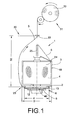
- the Fig.1 schematically shows a workstation 30 of a (not shown) double-twisting machine or cabling.
- Such workstations 30 have inter alia a double-twisting or cabling spindle 1, with a supply bobbin 4 mounted in a stationary protective pot 3, and a winding device 31 for winding the twisted yarn 5 into a package 32.
- the stationary protective pot 3 which has a relatively large diameter D, has a pot bottom 2. Below the
- Pot bottom 2 is a rotatably mounted spindle 6 of the double-twisting or cabling 1 arranged.
- the spindle 6 is provided for rotating and guiding the thread 5 during the twisting or Kablierluies with a storage disc 12 and a thread-Abschteller 13, wherein the diameter d of the thread-Abschtellers 13, in this case the largest diameter of rotatably mounted spindle 6 forms, as can be seen, significantly below the diameter D of the stationary protective pot 3.
- the thread 5 is then, as known and therefore not explained in more detail, acted upon within the coil axis 25 by a (not shown) yarn brake and guided over the rotationally driven spindle 6 to the outside.
- the thread 5 passes through a radial opening 40 in the storage disk 12 of the rotating spindle 6 on the circular circumferential or lateral surface of the storage disk 12, where it is temporarily stored, depending on the particular thread tension present.
- the thread 5 leaves the rotating spindle 6 in the illustrated embodiment on the thread-Abschteller 13, wherein the thread 5 during the twisting or Kablierreaes between a line of contact 23 in the region of the pot bottom 2 of the protective pot 3 and arranged above the protective pot 3, stationary balloon yarn guide 33 forms a relatively slim thread balloon 50.
- the twisted yarn 5 After passing through the stationary balloon yarn guide 33, the twisted yarn 5 is wound by means of the winding device 31 into a package 32.
- the Fig.2 shows in detail a first embodiment of the inventive double-wire twisting or Kablierspindel 1, wherein both the rotatably mounted spindle 6 and the upper bearing means 11 for the stationary protective pot 2 and arranged below the stationary protective cup 2 bearing means 7 for the spindle 6 in section are shown.
- the bearing devices 7 and 11 preferably each have two axially spaced-apart rolling bearings.
- the bearing device 7 is arranged in a bearing housing 9, which is fixed in a spindle bank 8 of the double-wire twisting or cabling machine, in which the spindle 6 of the double-wire twisting or cabling spindle 1 is rotatably mounted with its spindle shaft 43 ,
- a whorl 44 is pressed, which is acted upon during the twisting process by a drivable tangential belt 10.
- a bore 26 which serves to facilitate the threading of the thread 5 in the double-twisting or Kablierspindel 1 and which is connected via a pressure line 27 and a defined controllable valve means 28 with a compressed air source 29 ,
- a storage disk 12 is non-rotatably connected to an intermediate part 34, which is preferably part of the spindle shaft 43.
- a likewise connected rotationally fixed to the spindle shaft 43 spindle start part 35 forms the basis for the storage device 11 of the stationary protective pot.
- the bearing device 11 has, for example, two axially spaced-apart rolling bearings.
- the rolling bearings are fixed with their inner rings on the spindle start part 35, while the cup bottom 2 of the protective pot 3 is mounted on the outer rings of these bearings.
- the intermediate part 34 and the spindle starting part 35 are also provided with internal bores, with both the bore 36 of the spindle starting part 35 and the bore 37 of the intermediate part 34 merging into the radial opening 40 of the storage disc 12.
- a thread-Abschteller 13 whose largest diameter d clear, that is, at least 10% below the diameter D of the stationary protective pot 3.
- the yarn discharge plate 13 grips with play into a circular recess 15, which is arranged on the underside of the pot bottom 2 and opens downwards.
- the pot bottom 2 in the region of its outer side 16 on a thread-friendly designed deflection radius R.
- the size of this deflection radius can be between 8 and 20 mm, for example, depending on the number of yarn areas to be processed by the double-twisting or cabling spindle.
- the Figure 3 shows further embodiments of an inventively designed double-twisting or Kablierspindel. 1
- FIGS. 1 and 2 illustrated first embodiment of a double-twisting or Kablierspindel 1 An essential difference to that in the FIGS. 1 and 2 illustrated first embodiment of a double-twisting or Kablierspindel 1 is that in the embodiments according to Figure 3 the rotatably mounted spindle 6 has no thread-Abschteller.
- the thread 5 passes during the twisting or cabling through the coil axis 25 and the bore 36 to the radial bore 40 of the spindle. 6
- the emerging from the radial opening 40 thread 5 is ßie-rated temporarily stored on the circular peripheral or circumferential surface of the storage disk 12 before it is deflected in the direction of the pot bottom 2 of the stationary protective pot 2.
- the thread 5 touches the bottom of the pot 2 in the region of a contact line 23, wherein the line of contact 23 of the thread 5, depending on the embodiment of the pot bottom 2 and the protective pot 3, either in the region of a friction-friendly deflection radius 16 (see left side of the Figure 3 ) or, as shown on the right side of the image, in the region of a guide ring or a guide bead 17 fastened, for example, to the protective pot 3.
- the maximum diameter d of the spindle 6 results in each case from the diameter of the storage disk 12.
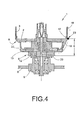
- This additional adapter 22 is disposed between the bottom of the pot 2 of the stationary protective pot 3 and the yarn discharge plate 13 of the spindle 6 and preferably rotatably connected to the protective pot 2.
- the distance a between the lower edge 20 of the storage disk 12 and the thread through the fifth During the twisting or Kablierreaes tangent touch line 23 can be increased to up to 120 mm.
- this area can either be open, as in the left half of the Figure 4 represented, or, as on the right half of the Figure 4 shown, by a conically shaped jacket piece 19, which is for example part of the pot bottom 2, to be bridged.
- the bottom of the pot 2 has in such an embodiment on its underside on a pointing down conical extension.
- the conical projection 19 starts preferably just below the touched by the thread 5 during the twisting or Kablierreaes, formed for example by a guide ring 17 contact line 23 and ends just above the thread-Abschtellers 13 of the rotatably mounted spindle. 6
- the protective pot can simply be enlarged by the length of an adapter downwards.
- the area of the contact line 23 can be either, for example, as on the left side of FIG Figure 4 be defused by a thread-friendly circumferential radius R, or, as shown on the right side of the Figure 4 indicated in the area of Touch line 23 is a guide ring 17 and a guide bead installed.
- the Figure 5 shows a double-twisting or Kablierspindel 1 with a stationary protective pot 3, which is formed below the tangential by the thread 5 during the twisting or Kablierreaes contact line 23, in the region preferably a guide bead or a guide ring 17 is arranged conical.
- conical feed bobbins 4A are stored, as well as biconical feed bobbins 4B, as shown on the right half of the picture.
Landscapes
- Engineering & Computer Science (AREA)
- Mechanical Engineering (AREA)
- Textile Engineering (AREA)
- Spinning Or Twisting Of Yarns (AREA)
Abstract
Description
- Doppeldraht-Zwirn- oder Kablierspindel
- Die Erfindung betrifft eine Doppeldraht-Zwirn- oder Kablierspindel gemäß dem Oberbegriff des Anspruchs 1.
- Moderne Doppeldraht-Zwirn- oder Kablierspindeln verfügen üblicherweise über einen stationären Schutztopf zur Aufnahme einer Vorlagespule, eine hohle Spulenachse zum Führen eines Fadens durch die Zwirnspindel sowie eine unterhalb der Vorlagespule angeordnete, rotierbar gelagerte, antreibbare Spindel.
- Das heißt, bei solchen Doppeldraht-Zwirn- oder Kablierspindeln wird der Faden von einer still stehenden Vorlagespule nach oben abgezogen, in das obere Ende der hohlen Spulenachse eingeführt und dabei nach unten abgelenkt.
- Innerhalb der Spulenachse wird der Faden über eine Fadenbremse geführt und verlässt den Bereich der Spulenachse anschließend über eine Radialöffnung, die in einem Bauteil der rotierbar gelagerten, antreibbaren Spindel angeordnet ist.
- Nach dem Austritt aus der Radialöffnung wird der Faden temporär auf einer Speicherscheibe der Spindel gespeichert, bevor er zu einem oberhalb des Schutztopfes angeordneten, stationären Ballonfadenführer geführt wird.
- Der Faden bildet dabei aufgrund der Rotation der Spindel zwischen einem im Bereich der Speicherscheibe angeordneten, so genannten Abwurfteller und einem oberhalb des Schutztopfes angeordneten Ballonfadenführer einen um den Schutztopf rotierenden Fadenballon.
- Nach dem Passieren des Ballonfadenführers wird der verzwirnte oder kablierte Faden durch eine Spulvorrichtung zu einer Auflaufspule aufgewickelt.
- Bei derartigen Doppeldraht-Zwirn- oder Kablierspindeln sind die Form und die Größe des sich während des Zwirnvorganges bildenden Fadenballons unter anderem abhängig vom Durchmesser des Faden-Abwurfelements der Spindel.
- Das heißt, die Doppeldraht-Zwirn- oder Kablierspindeln weisen oft, wie zum Beispiel in der
DE 10 2006 029 055 A1 beschrieben, eine mittels eines Tangentialriemens angetriebene Spindel auf, die ihrerseits über eine umlaufende Speicherscheibe sowie über einen oberhalb der Speicherscheibe angeordneten, an der Speicherscheibe festgelegten Faden-Abwurfteller verfügt. - Um bei reibungsempfindlichen Garnmaterialien, wie beispielsweise Polypropylen, Polyester oder Polyacryl, zu verhindern, dass der Fadenballon während des Zwirnprozesses mit dem stationären Schutztopf in Kontakt kommt, was die Gefahr eines Fadenbruches in sich birgt, ist der Durchmesser dieses bekannten Faden-Abwurftellers so bemessen, dass er über dem Durchmesser des stationären Schutztopfes liegt.
- Daraus ergibt sich, dass der zwischen dem Faden-Abwurfteller und dem oberhalb des Schutztopfes angeordneten Ballonfadenführer kreisende Fadenballon in der Regel einen relativ großen Durchmesser aufweist.
- Da große Fadenballone jedoch bekanntlich zu relativ großen Ventilationsverlusten und damit zu erhöhtem Energiebedarf der Doppeldraht-Zwirnspindel führen, hat man, insbesondere im Zusammenhang mit weniger reibungsempfindlichen Garnmaterialien, wie zum Beispiel Baumwolle, in der Vergangenheit bereits verschiedene Versuche unternommen, um den Durchmesser der Fadenballone zu verkleinern bzw. zu begrenzen.
- In der
DE 44 04 555 C1 sind beispielsweise Doppeldraht-Zwirnspindeln beschrieben, die zusätzlich zu einem die Vorlagespule aufnehmenden, stationären Schutztopf einen den Schutztopf umfassenden, zylinderartigen Ballonbegrenzer aufweisen. - Bei derartigen Doppeldraht-Zwirnspindeln wird die Entstehung eines im Durchmesser relativ großen Fadenballons dadurch wirkungsvoll verhindert, dass der Faden nach dem Verlassen des im Durchmesser relativ großen Faden-Abwurftellers der Spindel sofort an die Innenseite des Ballonbegrenzers anläuft.
- Nachteilig bei diesen bekannten Doppeldraht-Zwirnspindeln ist allerdings der relativ lange körperliche Kontakt des umlaufenden Fadenballons mit dem stationären Ballonbegrenzer.
- Da die durch solche stationären Ballonbegrenzer auf den Faden einwirkenden Beanspruchungen verhältnismäßig hoch sind, sind solche Doppeldraht-Zwirnspindeln nur für relativ unempfindliche Garne einsetzbar.
- Vergleichbare Doppeldraht-Zwirnspindeln mit stationären Ballonbegrenzern sind auch durch die
DE-OS 1 813 801 DE 33 47 318 A1 bekannt. - Bei der Doppeldraht-Zwirnspindel gemäß
DE-OS 1 813 801 - Um Kontakte zwischen dem umlaufenden, nach außen an einem zylindrischen Ballonbegrenzer abgestützten Fadenballon und der Vorlagespule zu vermeiden, ist bei diesen Doppeldraht-Zwirnspindeln außerdem ein zwischen dem Ballonbegrenzer und der Vorlagespule angeordneter, zylinderförmiger Fadenführer vorgesehen, der die Vorlagespule in Höhe der Ballonbegrenzeroberkante umgibt.
- Die Doppeldraht-Zwirnspindel gemäß
DE 33 47 318 A1 verfügt über einen wuchtig ausgebildeten, zylindrischen Ballonbegrenzer, in dem ein stationärer Schutztopf, der konisch ausgebildete Endbereiche aufweist, gelagert ist. - Das bedeutet, auch bei den durch die
DE-OS 1 813 801 DE 33 47 318 A1 bekannten Doppeldraht-Zwirnspindeln ist der maximale Durchmesser des entstehenden Fadenballons durch den Innendurchmesser eines stationären, äußeren Ballonbegrenzers vorgegeben, so dass die zu bearbeitenden Fäden während des Zwirnprozesses nicht unerheblich belastet werden. - Des Weiteren sind in der
DE 29 31 391 C2 eine Doppeldraht-Zwirnspindel beschrieben, bei der der stationäre Schutztopf, der im Bodenbereich über einen Vorratsbehälter für ein Gleitmittel verfügt, etwas konvex gerundet ist. - Der Schutztopf ist im Bereich des Vorratsbehälters außerdem mit einer Ringscheibe ausgestattet, die aus einem saugfähigen Material besteht.
- Bei dieser bekannten Doppeldraht-Zwirnspindel gleitet der Faden nach dem Verlassen des im Durchmesser relativ großen Faden-Abwurftellers der Spindel über die Ringscheibe am Schutztopf und wird dabei mit einer Avivage bzw. einem Aviviermittel benetzt.
- Ausgehend vom vorstehend beschriebenen Stand der Technik liegt der Erfindung die Aufgabe zugrunde, eine Doppeldraht-Zwirn- oder Kablierspindel so zu modifizieren, dass die während des Zwirnoder Kablierprozesses entstehenden Fadenballone möglichst schlank sind, wobei die vorstehend beschriebenen Nachteile, insbesondere das Entlanggleiten des Fadens an einem äußeren, stationären Ballonbegrenzer, vermieden werden sollen.
- Diese Aufgabe wird erfindungsgemäß durch eine Doppeldraht-Zwirnoder Kablierspindel gelöst, die die im Anspruch 1 beschriebenen Merkmale aufweist.
- Vorteilhafte Ausgestaltungen der Erfindung sind Gegenstand der Unteransprüche.
- Mit einer Doppeldraht-Zwirn- oder Kablierspindel, deren rotierbar gelagerte Hohlspindel einen größten Durchmesser aufweist, der mindestens 10 % unter dem Durchmesser der Berührungslinie des Topfbodens des stationären Schutztopfes mit dem Faden liegt, lassen sich während des Zwirnprozesses zuverlässig relativ schlanke Fadenballone realisieren.
- Diese schlanken Fadenballone haben den Vorteil, dass die während des Betriebes an den Doppeldraht-Zwirn- oder Kablierspindeln auftretenden Ventilationsverluste deutlich reduziert werden, was zu einer spürbaren Verminderung der beim Betrieb solcher Doppeldraht-Zwirn- oder Kablierspindeln benötigten Antriebsenergie führt.
- Wie im Anspruch 2 beschrieben, ist in vorteilhafter Ausführungsform vorgesehen, dass die rotierbar gelagerte Spindel, die den Faden während des Zwirn- oder Kablierprozesses führt, eine Speicherscheibe aufweist, auf deren Mantelfläche der Faden gleitet.
- Da eine solche Speicherscheibe ohnehin notwendig ist, um die während des Zwirn- oder Kablierprozesses auftretenden Fadenspannungsschwankungen durch temporäre Speicherung des Fadens auszugleichen, stellt die Verwendung der Speicherscheibe als Fadenabwurfelement eine kostengünstige Ausführungsform dar.
- Das heißt, bei der im Anspruch 2 verwendeten Ausführungsform wird auf den Einsatz eines Faden-Abwurftellers verzichtet.
- In alternativer Ausführungsform kann allerdings auch, wie im Anspruch 3 beschrieben, vorgesehen sein, dass die Spindel außer der Speicherscheibe auch einen an der Speicherscheibe festgelegten Faden-Abwurfteller aufweist.
- Ein solcher Faden-Abwurfteller ist in der Regel oben auf der Speicherscheibe festgelegt und stellt ein vorteilhaftes Fadenführungsmittel dar.
- Das heißt, durch einen solchen Faden-Abwurfteller wird sichergestellt, dass der Faden nach dem Verlassen der Speicherscheibe schonend nach oben geführt wird und dabei einen schlanken Fadenballon bildet.
- Gemäß Anspruch 4 ist in vorteilhafter Ausführungsform außerdem vorgesehen, dass der Faden-Abwurfteller einen kurvenförmig ausgebildeten Randbereich aufweist, der während des Zwirn- oder Kablierprozesses mit Spiel in einer ringförmigen, nach unten offenen Aussparung des Topfbodens des Schutztopfes umläuft. Durch eine solche Ausbildung können die üblicherweise im Randbereich eines rotierenden Faden-Abwurftellers auftretenden Luftverwirbelungen minimiert werden.
- Wie im Anspruch 5 beschrieben ist, ist in vorteilhafter Ausführungsform des Weiteren vorgesehen, dass der Topfboden des stationären Schutztopfes an seiner Außenseite, an der der Faden während des Zwirn- oder Kablierprozesses entlang gleitet, einen fadenfreundlichen Umlenkradius aufweist.
- Durch einen solchen fadenfreundlichen Umlenkradius, dessen Maß zwischen 8 mm und 20 mm beträgt, wird gewährleistet, dass der während des Zwirn- oder Kablierprozesses am Topfboden entlang gleitende Faden nicht zu stark beansprucht oder gar geschädigt wird.
- In einer alternativen Ausführungsform, die im Anspruch 6 beschrieben ist, ist vorgesehen, dass unterhalb des stationären Schutztopfes ein Adapter angeordnet ist, der mit dem Topfboden des Schutztopfes drehfest verbunden ist.
- Durch das Einschalten eines solchen Adapters kann die Berührungsfläche des Fadens am Topfboden minimiert und gleichzeitig der während des Zwirnprozesses entstehende Fadenballon schlanker gestaltet werden.
- Zur Optimierung der Fadenführung unterhalb des Schutztopfes kann außerdem vorgesehen sein, dass der Adapter durch ein am Topfboden angeordnetes, bis an den Abwurfteller reichendes, konisch ausgebildetes Mantelstück überfasst wird (Anspr.7).
- Wie im Anspruch 8 beschrieben, ist in einer weiteren alternativen Ausführungsform vorgesehen, dass der Schutztopf unterhalb der Berührungslinie des Fadens mit dem Schutztopf einen konisch ausgebildeten Bereich aufweist.
- Durch eine solche Ausbildung des Schutztopfes wird auf einfache Weise eine optimale Aufnahme konischer oder bikonischer Vorlagespulen im Schutztopf ermöglicht.
- Das heißt, der Schutztopf kann auch bei der Verarbeitung derartiger ausgebildeter Vorlagespule stets maximal bestückt werden.
- Um zuverlässig sicherzustellen, dass der Faden während des Zwirn- oder Kablierprozesses im Bereich seiner Berührungslinie schonend geführt ist, ist in vorteilhafter Ausführungsform vorgesehen, dass der Schutztopf in diesem Bereich mit einem Führungsring oder einer Führungswulst ausgestattet ist (Anspr.9).
- Der Führungsring bzw. die Führungswulst sind dabei vorzugsweise aus einem harten und fadenfreundlichen Material, zum Beispiel aus verchromten oder polierten Stahl, gefertigt und sorgen dafür, dass der Faden während des Zwirn- oder Kablierprozesses durch den stationären Schutztopf nicht geschädigt werden kann. Wie in den Ansprüchen 10 und 11 dargelegt, ist der Führungsring bzw. die Führungswulst entweder am Topfboden des Schutztopfes befestigt oder im unteren Teil der Topfmantelfläche des Schutztopfes festgelegt. Beide Standorte haben sich in der Praxis als vorteilhaft erwiesen.
- Um während des Zwirnprozesses einen möglichst schlanken Fadenballon realisieren zu können, ist gemäß Anspruch 12 vorgesehen, dass zwischen der während des Zwirnprozesses durch den Faden berührten Umfangslinie des Schutztopfes und der Unterkante der Speicherscheibe ein Abstand a gegeben ist, der zwischen 1 und 120 mm betragen kann.
- Ein solcher relativ großer Abstand kann auf einfache Weise durch den Einsatz eines Adapters erreicht werden, der unterhalb des Schutztopfes positioniert ist.
- Wie bereits im Zusammenhang mit Anspruch 6 erläutert, führt ein relativ großer Abstand a dazu, dass der während des Zwirnprozesses entstehende Fadenballon gestreckt und damit schlank gehalten wird.
- Weitere Einzelheiten der Erfindung sind den nachfolgend anhand der Figuren erläuterten Ausführungsbeispielen entnehmbar.
- Es zeigt:
- Fig.1
- schematisch eine Arbeitsstelle einer Doppeldraht-Zwirn-maschine, wobei die Doppeldraht-Zwirn- oder Kablierspindel über einen stationären Schutztopf verfügt, in dem eine Vorlagespule angeordnet ist, und eine rotierbar gelagerte Spindel vorgesehen ist, deren größter Durchmesser erheblich unter dem Durchmesser des Schutztopfes liegt,
- Fig.2
- im Schnitt ein erstes Ausführungsbeispiel einer Doppeldraht-Zwirn- oder Kablierspindel, wobei die rotierbar gelagerte Spindel der Doppeldraht-Zwirn- oder Kablierspindel mit einer Speicherscheibe und einem Abwurfteller ausgestattet ist,
- Fig.3
- im Schnitt weitere Ausführungsbeispiele einer Doppeldraht-Zwirn- oder Kablierspindel, deren rotierbar gelagerte Spindel jeweils lediglich mit einer Speicherscheibe ausgerüstet ist,
- Fig.4
- weitere Ausführungsbeispiele einer Doppeldraht-Zwirnoder Kablierspindel, wobei zwischen den stationären Schutztopf und den Abwurfteller der rotierbar gelagerten Spindel jeweils ein Adapter eingeschaltet ist, ebenfalls im Schnitt,
- Fig.5
- weitere Ausführungsbeispiele einer Doppeldraht-Zwirnoder Kablierspindel, wobei der Schutztopf zur Aufnahme einer konischen oder einer bikonischen Vorlagespule konzipiert ist.
- Die
Fig.1 zeigt schematisch eine Arbeitsstelle 30 einer (nicht näher dargestellten) Doppeldraht-Zwirn- oder Kabliermaschine. Derartige Arbeitsstellen 30 verfügen unter anderem über eine Doppeldraht-Zwirn- oder Kablierspindel 1, mit einer in einem stationären Schutztopf 3 gelagerten Vorlagespule 4 sowie über eine Spulvorrichtung 31 zum Aufwickeln des gezwirnten Fadens 5 zu einer Auflaufspule 32. - Der stationäre Schutztopf 3, der einen relativ großen Durchmesser D aufweist, verfügt über einen Topfboden 2. Unterhalb des
- Topfbodens 2 ist eine rotierbar gelagerte Spindel 6 der Doppeldraht-Zwirn- oder Kablierspindel 1 angeordnet.
- In dem in
Fig.1 dargestellten Ausführungsbeispiel ist die Spindel 6 zum Rotieren und Führen des Fadens 5 während des Zwirn- oder Kablierprozesses mit einer Speicherscheibe 12 sowie mit einem Faden-Abwurfteller 13 ausgestattet, wobei der Durchmesser d des Faden-Abwurftellers 13, der in diesem Fall den größten Durchmesser der rotierbar gelagerten Spindel 6 bildet, wie ersichtlich, deutlich unter dem Durchmesser D des stationären Schutztopfes 3 liegt. - Wie in
Fig.1 weiter dargestellt, wird während des Zwirn- oder Kablierbetriebes ein durch einen rotierbar gelagerten Fadenführer 24 geführter Faden 5 von der Vorlagespule 4 abgezogen und von oben in die hohle Spulenachse 25 der Doppeldraht-Zwirn- oder Kablierspindel 1 eingefädelt. - Der Faden 5 wird anschließend, wie bekannt und daher nicht näher erläutert, innerhalb der Spulenachse 25 durch eine (nicht dargestellte) Fadenbremse beaufschlagt und über die rotierend angetriebene Spindel 6 nach außen geführt.
- Das heißt, der Faden 5 gelangt über eine Radialöffnung 40 in der Speicherscheibe 12 der rotierenden Spindel 6 auf die kreisrunde Umfangs- oder Mantelfläche der Speicherscheibe 12, wo er, abhängig von der jeweils vorliegenden Fadenspannung, temporär gespeichert wird.
- Der Faden 5 verlässt die rotierende Spindel 6 im dargestellten Ausführungsbeispiel über den Faden-Abwurfteller 13, wobei der Faden 5 während des Zwirn- oder Kablierprozesses zwischen einer Berührungslinie 23 im Bereich des Topfbodens 2 des Schutztopfes 3 und einem oberhalb des Schutztopfes 3 angeordneten, stationären Ballonfadenführer 33 einen relativ schlanken Fadenballon 50 bildet.
- Nach dem Durchlaufen des stationären Ballonfadenführers 33 wird der gezwirnte Faden 5 mittels der Spulvorrichtung 31 zu einer Auflaufspule 32 aufgewickelt.
- Die
Fig.2 zeigt im Detail eine erste Ausführungsform der erfindungsgemäßen Doppeldraht-Zwirn- oder Kablierspindel 1, wobei sowohl die rotierbar gelagerte Spindel 6 als auch die obere Lagereinrichtung 11 für den stationären Schutztopf 2 und die unterhalb des stationären Schutztopfes 2 angeordnete Lagereinrichtung 7 für die Spindel 6 im Schnitt dargestellt sind. Wie angedeutet, weisen die Lagereinrichtungen 7 und 11 vorzugsweise jeweils zwei axial zueinander beabstandet angeordnete Wälzlager auf. - Wie weiter ersichtlich, ist in einem Lagergehäuse 9, das in einer Spindelbank 8 der Doppeldraht-Zwirn- oder Kabliermaschine festgelegt ist, die Lagereinrichtung 7 angeordnet, in der die Spindel 6 der Doppeldraht-Zwirn- oder Kablierspindel 1 mit ihrem Spindelschaft 43 rotierbar gelagert ist.
- Auf das untere Ende des Spindelschaftes 43 ist ein Wirtel 44 aufgepresst, der während des Zwirnprozesses durch einen antreibbaren Tangentialriemen 10 beaufschlagt wird.
- Vorzugsweise verläuft innerhalb des Spindelschaftes 43 sowie des Wirtels 44 eine Bohrung 26, die zum Erleichtern des Einfädelns des Fadens 5 in die Doppeldraht-Zwirn- oder Kablierspindel 1 dient und die über eine Druckleitung 27 und eine definiert ansteuerbare Ventileinrichtung 28 mit einer Druckluftquelle 29 verbunden ist.
- An ein Zwischenteil 34, das vorzugsweise Bestandteil des Spindelschaftes 43 ist, ist drehfest eine Speicherscheibe 12 angeschlossen.
- Ein ebenfalls drehfest mit dem Spindelschaft 43 verbundenes Spindelanfangsteil 35 bildet die Basis für die Lagereinrichtung 11 des stationären Schutztopfes 3.
- Die Lagereinrichtung 11 verfügt beispielsweise über zwei axial zu einander beabstandet angeordnete Wälzlager.
- Das heißt, die Wälzlager sind mit ihren Innenringen auf dem Spindelanfangsteil 35 festgelegt, während auf den Außenringen dieser Wälzlager der Topfboden 2 des Schutztopfes 3 gelagert ist.
- Wie ersichtlich, sind auch das Zwischenteil 34 und das Spindelanfangsteil 35 mit Innenbohrungen ausgestattet, wobei sowohl die Bohrung 36 des Spindelanfangsteils 35 als auch die Bohrung 37 des Zwischenteils 34 in die Radialöffnung 40 der Speicherscheibe 12 übergeht.
- Gemäß dem in
Fig.2 dargestellten ersten Ausführungsbeispiel ist auf der Speicherscheibe 12, beispielsweise mittels Schraubenbolzen 41, ein Faden-Abwurfteller 13 befestigt, dessen größter Durchmesser d deutlich, das heißt, mindestens 10% unter dem Durchmesser D des stationären Schutztopfes 3 liegt. - Der Faden-Abwurfteller 13 fasst dabei mit seinem nach oben gebogenen Randbereich 14 mit Spiel in eine auf der Unterseite des Topfbodens 2 angeordnete, nach unten hin offene, kreisförmige Aussparung 15.
- Wie aus der
Fig.2 weiter ersichtlich, weist der Topfboden 2 im Bereich seiner Außenseite 16 einen fadenfreundlich gestalteten Umlenkradius R auf. Die Größe dieses Umlenkradius' kann, zum Beispiel abhängig von dem durch die Doppeldraht-Zwirn- oder Kablierspindel zu verarbeitenden Garnnummernbereich, zwischen 8 und 20 mm betragen. - Die
Fig.3 zeigt weitere Ausführungsformen einer erfindungsgemäß ausgebildeten Doppeldraht-Zwirn- oder Kablierspindel 1. - Ein wesentlicher Unterschied zu der in den
Figuren 1 und2 dargestellten ersten Ausführungsform einer Doppeldraht-Zwirn- oder Kablierspindel 1 ist, dass bei den Ausführungsformen gemäßFig.3 die rotierbar gelagerte Spindel 6 keinen Faden-Abwurfteller aufweist. - Wie in
Fig.3 dargestellt, gelangt der Faden 5 während des Zwirnoder Kablierprozesses durch die Spulenachse 25 bzw. die Bohrung 36 zur Radialbohrung 40 der Spindel 6. - Der aus der Radialöffnung 40 austretende Faden 5 wird anschlie-βend temporär auf der kreisrunden Umfangs- oder Mantelfläche der Speicherscheibe 12 gespeichert, bevor er in Richtung des Topfbodens 2 des stationären Schutztopfes 2 abgelenkt wird.
- Der Faden 5 tangiert den Topfboden 2 dabei im Bereich einer Berührungslinie 23, wobei die Berührungslinie 23 des Fadens 5, je nach Ausführungsform des Topfbodens 2 bzw. des Schutztopfes 3, entweder im Bereich eines reibungsfreundlichen Umlenkradius 16 (siehe linke Bildseite der
Fig.3 ) oder, wie auf der rechten Bildseite dargestellt, im Bereich eines beispielsweise am Schutztopf 3 befestigten Führungsringes bzw. eines Führungswulstes 17 liegt. - Bei diesen Ausführungsformen ergibt sich der maximale Durchmesser d der Spindel 6 jeweils aus dem Durchmesser der Speicherscheibe 12.
- Die in der
Fig.4 dargestellten Ausführungsformen einer Doppeldraht-Zwirn- oder Kablierspindel 1 unterscheiden sich insbesondere von der in denFiguren 1 und2 dargestellten Ausführungsform einer Doppeldraht-Zwirn- oder Kablierspindel 1 durch einen zusätzlichen Adapter 22. - Dieser zusätzliche Adapter 22 ist zwischen dem Topfboden 2 des stationären Schutztopfes 3 und dem Faden-Abwurfteller 13 der Spindel 6 angeordnet und vorzugsweise drehfest mit dem Schutztopf 2 verbunden.
- Durch einen solchen Adapter 22 kann der Abstand a zwischen der Unterkante 20 der Speicherscheibe 12 und der durch den Faden 5 während des Zwirn- oder Kablierprozesses tangierten Berührungslinie 23 auf bis zu 120 mm vergrößert werden.
- Bei der Ausführungsform einer Doppeldraht-Zwirn- oder Kablierspindel 1 mit Adapter 22 kann dieser Bereich entweder offen liegen, wie auf der linken Bildhälfte der
Fig.4 dargestellt, oder, wie auf der rechten Bildhälfte derFig.4 gezeigt, durch ein konisch ausgebildetes Mantelstück 19, das zum Beispiel Teil des Topfbodens 2 ist, überbrückt sein. - Das heißt, der Topfboden 2 weist bei einer solchen Ausführungsform auf seiner Unterseite eine nach unter weisende konische Verlängerung auf. Der konische Ansatz 19 beginnt dabei vorzugsweise knapp unterhalb der vom Faden 5 während des Zwirn- oder Kablierprozesses tangierten, beispielsweise durch einen Führungsring 17 gebildeten Berührungslinie 23 und endet knapp oberhalb des Faden-Abwurftellers 13 der rotierbar gelagerten Spindel 6.
- Selbstverständlich ist es auch möglich, den vorstehend beschriebenen Abstand a zwischen der Unterkante 20 der Speicherscheibe 12 und der durch den Faden 5 während des Zwirn- oder Kablierprozesses tangierten Berührungslinie 23 auf bis zu 120 mm zu vergrößern, ohne dass ein zusätzlicher, am Schutztopf festlegbarer Adapter zum Einsatz kommt.
- In einem solchen Fall kann beispielsweise der Schutztopf einfach um die Länge eines Adapters nach unten vergrößert sein.
- Auch bei den Ausführungsformen gemäß
Fig.4 sind im Bereich der vom Faden 5 während des Zwirn- oder Kablierprozesses tangierten Berührungslinie 23 verschiedene Ausbildungen möglich. - Der Bereich der Berührungslinie 23 kann beispielsweise entweder, wie auf der linken Bildseite der
Fig.4 dargestellt, durch einen fadenfreundlichen Umfangsradius R entschärft sein, oder, wie auf der rechten Bildseite derFig.4 angedeutet, im Bereich der Berührungslinie 23 ist ein Führungsring 17 bzw. ein Führungswulst installiert. - Die
Fig.5 zeigt eine Doppeldraht-Zwirn- oder Kablierspindel 1 mit einem stationären Schutztopf 3, der unterhalb der durch den Faden 5 während des Zwirn- oder Kablierprozesses tangierten Berührungslinie 23, in deren Bereich vorzugsweise eine Führungswulst oder ein Führungsring 17 angeordnet ist, konisch ausgebildet ist. - In einem solchermaßen teilweise konisch gestalteten Schutztopf 3 können vorteilhaft, das heißt, unter Ausnutzung des maximalen Aufnahmevolumens, sowohl, wie auf der linken Bildhälfte der
Fig.5 angedeutet, konische Vorlagespulen 4A gelagert werden, als auch bikonische Vorlagespulen 4B, wie dies auf der rechten Bildhälfte dargestellt ist.
Claims (12)
- Doppeldraht-Zwirn- oder Kablierspindel (1) mit einer auf einem Topfboden (2) eines stationären Schutztopfes (3) gelagerten Vorlagespule (4) sowie einer unterhalb des Schutztopfes (3) angeordneten Spindel (6), die einen zu bearbeitenden Faden (5) während des Zwirn- oder Kablierprozesses führt, wobei die Spindel (6) mittels einer unteren Lagereinrichtung (7) in einem an einer Spindelbank (8) festlegbaren Lagergehäuse (9) drehbar gelagert und zur Lagerung des stationären Schutztopfes (3) eine weitere, obere Lagereinrichtung (11) vorgesehen ist,
dadurch gekennzeichnet,
dass der größte Durchmesser (d) der rotierbar gelagerten Spindel (6) mindestens 10% unter dem Durchmesser (D) der Berührungslinie (23) des Topfbodens (2) des stationären Schutztopfes (3) mit dem Faden (5) liegt. - Doppeldraht-Zwirn- oder Kablierspindel nach Anspruch 1,
dadurch gekennzeichnet, dass die Spindel (6) eine Speicherscheibe (12) aufweist, auf deren Umfangsfläche der zu bearbeitende Faden (5) während des Zwirn- oder Kablierprozesses temporär geführt ist. - Doppeldraht-Zwirn- oder Kablierspindel nach Anspruch 1,
dadurch gekennzeichnet, dass die Spindel (6) eine Speicherscheibe (12) sowie einen an die Speicherscheibe (12) angeschlossenen Faden-Abwurfteller (13) aufweist. - Doppeldraht-Zwirn- oder Kablierspindel nach Anspruch 3,
dadurch gekennzeichnet, dass der Faden-Abwurfteller (13) einen kurvenförmig ausgebildeten Randbereich (14) aufweist, der während des Zwirn- oder Kablierbetriebs mit Spiel in einer ringförmigen, nach unten offenen Aussparung (15) des Topfbodens (2) des Schutztopfes (3) umläuft. - Doppeldraht-Zwirn- oder Kablierspindel nach Anspruch 1,
dadurch gekennzeichnet, dass der Topfboden (2) an seiner Außenseite (16), an der der Faden (5) während des Zwirn- oder Kablierprozesses entlang gleitet, einen reibungsfreundlichen Umlenkradius (R) aufweist, der zwischen 8 und 20 mm beträgt. - Doppeldraht-Zwirn- oder Kablierspindel nach Anspruch 1,
dadurch gekennzeichnet, dass unterhalb des Schutztopfes (3) ein Adapter (22) angeordnet ist. - Doppeldraht-Zwirn- oder Kablierspindel nach Anspruch 6,
dadurch gekennzeichnet, dass der Adapter (22) durch ein am Topfboden (2) angeordnetes, bis an den Abwurfteller (13) reichendes, konisch ausgebildetes Mantelstück (19) überfasst wird. - Doppeldraht-Zwirn- oder Kablierspindel nach Anspruch 1,
dadurch gekennzeichnet, dass der Schutztopf (3) unterhalb der Berührungslinie (23) einen konisch ausgebildeten Bereich (21) aufweist, der eine optimale Aufnahme konischer (4A) oder bikonischer (4B) Vorlagespulen im Schutztopf (3) ermöglicht. - Doppeldraht-Zwirn- oder Kablierspindel nach Anspruch 1,
dadurch gekennzeichnet, dass der Schutztopf (3) im Bereich der Berührungslinie (23) mit einem Führungsring oder einer Führungswulst (17) ausgestattet ist, an dem der Faden (5) während des Zwirn- oder Kablierprozesses entlang gleitet. - Doppeldraht-Zwirn- oder Kablierspindel nach Anspruch 9,
dadurch gekennzeichnet, dass der Führungsring bzw. der Führungswulst (17) am Topfboden (2) des Schutztopfes (3) befestigt ist. - Doppeldraht-Zwirn- oder Kablierspindel nach Anspruch 9,
dadurch gekennzeichnet, dass der Führungsring bzw. der Führungswulst (17) im unteren Teil der Topfmantelfläche (18) des Schutztopfes (3) befestigt ist. - Doppeldraht-Zwirn- oder Kablierspindel nach einem der vorherigen Ansprüche, dadurch gekennzeichnet, dass zwischen der während der Berührungslinie (23) und der Unterkante (20) der Speicherscheibe (12) ein Abstand (a) gegeben ist, der zwischen 1 und 120 mm beträgt.
Applications Claiming Priority (1)
| Application Number | Priority Date | Filing Date | Title |
|---|---|---|---|
| DE102010013795A DE102010013795A1 (de) | 2010-04-03 | 2010-04-03 | Doppeldraht-Zwirnspindel |
Publications (2)
| Publication Number | Publication Date |
|---|---|
| EP2371999A1 true EP2371999A1 (de) | 2011-10-05 |
| EP2371999B1 EP2371999B1 (de) | 2012-11-14 |
Family
ID=44275645
Family Applications (1)
| Application Number | Title | Priority Date | Filing Date |
|---|---|---|---|
| EP11001729A Not-in-force EP2371999B1 (de) | 2010-04-03 | 2011-03-02 | Doppeldraht-Zwirn- oder Kablierspindel |
Country Status (4)
| Country | Link |
|---|---|
| US (1) | US8307622B2 (de) |
| EP (1) | EP2371999B1 (de) |
| CN (1) | CN102212903B (de) |
| DE (1) | DE102010013795A1 (de) |
Cited By (1)
| Publication number | Priority date | Publication date | Assignee | Title |
|---|---|---|---|---|
| CN103832882A (zh) * | 2014-02-19 | 2014-06-04 | 苏州市职业大学 | 一种化纤收卷控制装置 |
Families Citing this family (10)
| Publication number | Priority date | Publication date | Assignee | Title |
|---|---|---|---|---|
| CN102965778B (zh) * | 2012-11-20 | 2015-07-01 | 宜昌经纬纺机有限公司 | 一种直捻与倍捻通用的气动生头装置及直倍捻气动生头方法 |
| CN104195687A (zh) * | 2014-08-26 | 2014-12-10 | 宜昌经纬纺机有限公司 | 一种节能电锭组件 |
| CN104195688A (zh) * | 2014-08-26 | 2014-12-10 | 宜昌经纬纺机有限公司 | 一种节能电锭组件 |
| CN104195689A (zh) * | 2014-08-26 | 2014-12-10 | 宜昌经纬纺机有限公司 | 一种节能电锭组件 |
| DE102014018039A1 (de) * | 2014-12-05 | 2016-06-09 | Saurer Germany Gmbh & Co. Kg | Mehrfachdraht-Zwirnspindel für Zwirnmaschinen |
| DE102015014383A1 (de) * | 2015-11-09 | 2017-05-11 | Saurer Germany Gmbh & Co. Kg | Verfahren zum Betreiben einer Spindel einer Doppeldrahtzwirn- oder Kabliermaschine |
| DE102015014382A1 (de) * | 2015-11-09 | 2017-05-11 | Saurer Germany Gmbh & Co. Kg | Arbeitsstelle einer Doppeldrahtzwirn-oder Kabliermaschine |
| CN107904719A (zh) * | 2017-12-23 | 2018-04-13 | 新昌县羽林街道元洋机械厂 | 一种真丝倍捻机锭子防丝线缠绕装置 |
| CN108532043A (zh) * | 2018-06-15 | 2018-09-14 | 嵊州市南丰机械有限公司 | 多功能锭子 |
| CN117779253A (zh) * | 2024-02-01 | 2024-03-29 | 浙江精工智能纺织机械有限公司 | 一种捻线机用锭子可加捻、包覆组合装置 |
Citations (6)
| Publication number | Priority date | Publication date | Assignee | Title |
|---|---|---|---|---|
| DE1086158B (de) * | 1956-05-05 | 1960-07-28 | Spinn Und Zwirnereimaschb Karl | Doppeldrahtzwirnspindel, insbesondere fuer schwere Zwirne, mit durch Magnete gehaltenem Spulentraegerkoerper |
| DE1813801A1 (de) | 1968-12-10 | 1970-07-02 | Hamel Gmbh Zwirnerei U Spinner | Doppeldrahtzwirnanordnung |
| DE2931391C2 (de) | 1979-08-02 | 1982-06-03 | Palitex Project-Company Gmbh, 4150 Krefeld | Doppeldraht-Zwirnspindel mit Vorratsbehälter für ein Gleitmittel |
| DE3347318A1 (de) | 1982-12-28 | 1984-07-05 | Murata Kikai K.K., Kyoto | Spanneinrichtung fuer eine doppeldrahtzwirnmaschine |
| DE4404555C1 (de) | 1994-02-12 | 1995-06-14 | Palitex Project Co Gmbh | Verfahren zum getrennten Einfädeln von zwei von zwei gleichachsig übereinander angeordneten Vorlagespulen abgezogenen Einzelfäden in die zweigeteilte Hohlachse einer Doppeldraht-Zwirnspindel und Doppeldraht-Zwirnspindel |
| DE102006029055A1 (de) | 2006-06-24 | 2007-12-27 | Oerlikon Textile Gmbh & Co. Kg | Doppeldraht-Zwirnspindel mit druckluftbetätigter Einfädelvorrichtung |
Family Cites Families (8)
| Publication number | Priority date | Publication date | Assignee | Title |
|---|---|---|---|---|
| DE440455C (de) | 1927-02-07 | Kaethe Klein | Vorrichtung zum Ausscheiden von Kohlenrueckstaenden aus Asche | |
| FR1397135A (fr) * | 1963-05-27 | 1965-04-30 | Pain Bourgeas Ets | Dispositif de double torsion pour fils textiles |
| US3855773A (en) * | 1973-05-07 | 1974-12-24 | Phillips Fibers Corp | Two-for-one twister |
| US5361571A (en) * | 1991-08-29 | 1994-11-08 | Joyce Michael F | Magnetic pot stabilizer |
| DE19755824C2 (de) * | 1996-12-18 | 2000-05-04 | Saurer Allma Gmbh | Doppeldrahtzwirnspindel zum Verdrehen von Naturseide |
| DE19726450C1 (de) * | 1997-06-21 | 1998-07-02 | Hamel Ag | Mehrfachdraht-Zwirnspindel mit rotierendem Ballonbegrenzer |
| US20030110753A1 (en) * | 2002-09-23 | 2003-06-19 | Josep Galan Pujol | Single position double twisting twister with precision weave pick up |
| CN201367500Y (zh) * | 2009-03-02 | 2009-12-23 | 朱爱萍 | 短纤倍捻锭子的扩容式储纱罐 |
-
2010
- 2010-04-03 DE DE102010013795A patent/DE102010013795A1/de not_active Withdrawn
-
2011
- 2011-03-02 EP EP11001729A patent/EP2371999B1/de not_active Not-in-force
- 2011-03-23 CN CN201110070586.5A patent/CN102212903B/zh not_active Expired - Fee Related
- 2011-04-01 US US13/078,465 patent/US8307622B2/en not_active Expired - Fee Related
Patent Citations (6)
| Publication number | Priority date | Publication date | Assignee | Title |
|---|---|---|---|---|
| DE1086158B (de) * | 1956-05-05 | 1960-07-28 | Spinn Und Zwirnereimaschb Karl | Doppeldrahtzwirnspindel, insbesondere fuer schwere Zwirne, mit durch Magnete gehaltenem Spulentraegerkoerper |
| DE1813801A1 (de) | 1968-12-10 | 1970-07-02 | Hamel Gmbh Zwirnerei U Spinner | Doppeldrahtzwirnanordnung |
| DE2931391C2 (de) | 1979-08-02 | 1982-06-03 | Palitex Project-Company Gmbh, 4150 Krefeld | Doppeldraht-Zwirnspindel mit Vorratsbehälter für ein Gleitmittel |
| DE3347318A1 (de) | 1982-12-28 | 1984-07-05 | Murata Kikai K.K., Kyoto | Spanneinrichtung fuer eine doppeldrahtzwirnmaschine |
| DE4404555C1 (de) | 1994-02-12 | 1995-06-14 | Palitex Project Co Gmbh | Verfahren zum getrennten Einfädeln von zwei von zwei gleichachsig übereinander angeordneten Vorlagespulen abgezogenen Einzelfäden in die zweigeteilte Hohlachse einer Doppeldraht-Zwirnspindel und Doppeldraht-Zwirnspindel |
| DE102006029055A1 (de) | 2006-06-24 | 2007-12-27 | Oerlikon Textile Gmbh & Co. Kg | Doppeldraht-Zwirnspindel mit druckluftbetätigter Einfädelvorrichtung |
Cited By (2)
| Publication number | Priority date | Publication date | Assignee | Title |
|---|---|---|---|---|
| CN103832882A (zh) * | 2014-02-19 | 2014-06-04 | 苏州市职业大学 | 一种化纤收卷控制装置 |
| CN103832882B (zh) * | 2014-02-19 | 2016-12-07 | 苏州市职业大学 | 一种化纤收卷控制装置 |
Also Published As
| Publication number | Publication date |
|---|---|
| US20110239617A1 (en) | 2011-10-06 |
| CN102212903A (zh) | 2011-10-12 |
| CN102212903B (zh) | 2015-08-19 |
| DE102010013795A1 (de) | 2011-10-06 |
| EP2371999B1 (de) | 2012-11-14 |
| US8307622B2 (en) | 2012-11-13 |
Similar Documents
| Publication | Publication Date | Title |
|---|---|---|
| EP2371999B1 (de) | Doppeldraht-Zwirn- oder Kablierspindel | |
| EP3168338B1 (de) | Arbeitsstelle einer doppeldrahtzwirn- oder kabliermaschine | |
| DD221984A5 (de) | Fadenliefervorrichtung fuer textilmaschinen | |
| EP1101847B1 (de) | Kablir- und Doppeldrahtzwirn-spindel mit druckluftbetätigter Einfädelvorrichtung | |
| DE7331545U (de) | Vorrichtung zum uebertragen von garndrehungen bei ringspinnmaschinen | |
| DE3124482C2 (de) | Bremsvorrichtung an einer Doppeldraht-Zwirnspindel | |
| DE4436790C2 (de) | Spinnstelle | |
| DE3916969A1 (de) | Fadenfuehrungsvorrichtung fuer eine doppeldrahtzwirnmaschine | |
| DE202015007655U1 (de) | Kablierspindel | |
| EP2784194A1 (de) | Fadenführeinrichtung für eine Textilmaschine, insbesondere für eine Ringspinnmaschine | |
| DE19726450C1 (de) | Mehrfachdraht-Zwirnspindel mit rotierendem Ballonbegrenzer | |
| EP0615010A1 (de) | Verfahren zum Aufbau einer definierten Fadenreserve an einem rotierenden Ballonbegrenzer einer Mehrfachdraht-Zwirnspindel und Mehrfachdraht-Zwirnspindel mit rotierendem Ballonbegrenzer | |
| EP3819411B1 (de) | Ringspinnmaschine sowie verfahren zum betreiben einer spinnstelle einer spinnmaschine | |
| DE3613163C2 (de) | ||
| DE10151167A1 (de) | Verfahren und Vorrichtung zum Kablieren oder Verzwirnen von mindestens zwei Fäden sowie Kablier- und/oder Doppeldrahtzwirn-Spindel zur Durchführung dieses Verfahrens | |
| DE2226284C3 (de) | Mehrfachdraht-Zwirnspindel zur Verarbeitung von Glasseide | |
| DE10220302A1 (de) | Kablierspindel sowie Verwendung einer selbsteinfädelnden Fadenführer- bzw. Zentrieröse im Bereich der Kablierhaube (Schutzhaube) einer Kablierspindel | |
| DE597022C (de) | Glockenspinn- und Glockenzwirnmaschine | |
| DE3732904C1 (de) | Doppeldraht-Zwirnspindel | |
| DE2919100A1 (de) | Einrichtung zur herstellung von zwirnen durch umwinden eines elastischen fadens mit einem oder mehreren deckfaeden | |
| DE1510820A1 (de) | Verfahren und Einrichtung zum Reduzieren des Zerfaserns und Brechens von Straengen | |
| DE4216283C2 (de) | Mehrfachdraht-Zwirnspindel | |
| DE4033951C1 (en) | Spinning unit to force yarn into helical course - has outer cap jacket with yarn guide component connecting to axial yarn guide duct | |
| DE2700820B2 (de) | Doppeldrahtzwirnspindel | |
| DE2945799C2 (de) | Einrichtung zum Umwinden eines Kernfadens |
Legal Events
| Date | Code | Title | Description |
|---|---|---|---|
| PUAI | Public reference made under article 153(3) epc to a published international application that has entered the european phase |
Free format text: ORIGINAL CODE: 0009012 |
|
| AK | Designated contracting states |
Kind code of ref document: A1 Designated state(s): AL AT BE BG CH CY CZ DE DK EE ES FI FR GB GR HR HU IE IS IT LI LT LU LV MC MK MT NL NO PL PT RO RS SE SI SK SM TR |
|
| AX | Request for extension of the european patent |
Extension state: BA ME |
|
| 17P | Request for examination filed |
Effective date: 20120405 |
|
| GRAP | Despatch of communication of intention to grant a patent |
Free format text: ORIGINAL CODE: EPIDOSNIGR1 |
|
| RIC1 | Information provided on ipc code assigned before grant |
Ipc: D01H 1/10 20060101ALI20120621BHEP Ipc: D01H 7/86 20060101AFI20120621BHEP Ipc: D01H 15/007 20060101ALI20120621BHEP |
|
| GRAS | Grant fee paid |
Free format text: ORIGINAL CODE: EPIDOSNIGR3 |
|
| GRAA | (expected) grant |
Free format text: ORIGINAL CODE: 0009210 |
|
| AK | Designated contracting states |
Kind code of ref document: B1 Designated state(s): AL AT BE BG CH CY CZ DE DK EE ES FI FR GB GR HR HU IE IS IT LI LT LU LV MC MK MT NL NO PL PT RO RS SE SI SK SM TR |
|
| REG | Reference to a national code |
Ref country code: GB Ref legal event code: FG4D Free format text: NOT ENGLISH |
|
| REG | Reference to a national code |
Ref country code: AT Ref legal event code: REF Ref document number: 584078 Country of ref document: AT Kind code of ref document: T Effective date: 20121115 Ref country code: CH Ref legal event code: EP |
|
| REG | Reference to a national code |
Ref country code: IE Ref legal event code: FG4D Free format text: LANGUAGE OF EP DOCUMENT: GERMAN |
|
| REG | Reference to a national code |
Ref country code: DE Ref legal event code: R096 Ref document number: 502011000190 Country of ref document: DE Effective date: 20130110 |
|
| REG | Reference to a national code |
Ref country code: NL Ref legal event code: VDEP Effective date: 20121114 |
|
| REG | Reference to a national code |
Ref country code: LT Ref legal event code: MG4D |
|
| PG25 | Lapsed in a contracting state [announced via postgrant information from national office to epo] |
Ref country code: FI Free format text: LAPSE BECAUSE OF FAILURE TO SUBMIT A TRANSLATION OF THE DESCRIPTION OR TO PAY THE FEE WITHIN THE PRESCRIBED TIME-LIMIT Effective date: 20121114 Ref country code: NO Free format text: LAPSE BECAUSE OF FAILURE TO SUBMIT A TRANSLATION OF THE DESCRIPTION OR TO PAY THE FEE WITHIN THE PRESCRIBED TIME-LIMIT Effective date: 20130214 Ref country code: LT Free format text: LAPSE BECAUSE OF FAILURE TO SUBMIT A TRANSLATION OF THE DESCRIPTION OR TO PAY THE FEE WITHIN THE PRESCRIBED TIME-LIMIT Effective date: 20121114 Ref country code: SE Free format text: LAPSE BECAUSE OF FAILURE TO SUBMIT A TRANSLATION OF THE DESCRIPTION OR TO PAY THE FEE WITHIN THE PRESCRIBED TIME-LIMIT Effective date: 20121114 Ref country code: HR Free format text: LAPSE BECAUSE OF FAILURE TO SUBMIT A TRANSLATION OF THE DESCRIPTION OR TO PAY THE FEE WITHIN THE PRESCRIBED TIME-LIMIT Effective date: 20121114 Ref country code: ES Free format text: LAPSE BECAUSE OF FAILURE TO SUBMIT A TRANSLATION OF THE DESCRIPTION OR TO PAY THE FEE WITHIN THE PRESCRIBED TIME-LIMIT Effective date: 20130225 |
|
| PG25 | Lapsed in a contracting state [announced via postgrant information from national office to epo] |
Ref country code: PT Free format text: LAPSE BECAUSE OF FAILURE TO SUBMIT A TRANSLATION OF THE DESCRIPTION OR TO PAY THE FEE WITHIN THE PRESCRIBED TIME-LIMIT Effective date: 20130314 Ref country code: LV Free format text: LAPSE BECAUSE OF FAILURE TO SUBMIT A TRANSLATION OF THE DESCRIPTION OR TO PAY THE FEE WITHIN THE PRESCRIBED TIME-LIMIT Effective date: 20121114 Ref country code: SI Free format text: LAPSE BECAUSE OF FAILURE TO SUBMIT A TRANSLATION OF THE DESCRIPTION OR TO PAY THE FEE WITHIN THE PRESCRIBED TIME-LIMIT Effective date: 20121114 Ref country code: GR Free format text: LAPSE BECAUSE OF FAILURE TO SUBMIT A TRANSLATION OF THE DESCRIPTION OR TO PAY THE FEE WITHIN THE PRESCRIBED TIME-LIMIT Effective date: 20130215 Ref country code: PL Free format text: LAPSE BECAUSE OF FAILURE TO SUBMIT A TRANSLATION OF THE DESCRIPTION OR TO PAY THE FEE WITHIN THE PRESCRIBED TIME-LIMIT Effective date: 20121114 |
|
| PG25 | Lapsed in a contracting state [announced via postgrant information from national office to epo] |
Ref country code: RS Free format text: LAPSE BECAUSE OF FAILURE TO SUBMIT A TRANSLATION OF THE DESCRIPTION OR TO PAY THE FEE WITHIN THE PRESCRIBED TIME-LIMIT Effective date: 20121114 Ref country code: BG Free format text: LAPSE BECAUSE OF FAILURE TO SUBMIT A TRANSLATION OF THE DESCRIPTION OR TO PAY THE FEE WITHIN THE PRESCRIBED TIME-LIMIT Effective date: 20130214 Ref country code: DK Free format text: LAPSE BECAUSE OF FAILURE TO SUBMIT A TRANSLATION OF THE DESCRIPTION OR TO PAY THE FEE WITHIN THE PRESCRIBED TIME-LIMIT Effective date: 20121114 Ref country code: SK Free format text: LAPSE BECAUSE OF FAILURE TO SUBMIT A TRANSLATION OF THE DESCRIPTION OR TO PAY THE FEE WITHIN THE PRESCRIBED TIME-LIMIT Effective date: 20121114 Ref country code: EE Free format text: LAPSE BECAUSE OF FAILURE TO SUBMIT A TRANSLATION OF THE DESCRIPTION OR TO PAY THE FEE WITHIN THE PRESCRIBED TIME-LIMIT Effective date: 20121114 |
|
| PG25 | Lapsed in a contracting state [announced via postgrant information from national office to epo] |
Ref country code: RO Free format text: LAPSE BECAUSE OF FAILURE TO SUBMIT A TRANSLATION OF THE DESCRIPTION OR TO PAY THE FEE WITHIN THE PRESCRIBED TIME-LIMIT Effective date: 20121114 Ref country code: NL Free format text: LAPSE BECAUSE OF FAILURE TO SUBMIT A TRANSLATION OF THE DESCRIPTION OR TO PAY THE FEE WITHIN THE PRESCRIBED TIME-LIMIT Effective date: 20121114 |
|
| REG | Reference to a national code |
Ref country code: CH Ref legal event code: NV Representative=s name: SCHMAUDER AND PARTNER AG PATENT- UND MARKENANW, CH Ref country code: CH Ref legal event code: PUE Owner name: ZHUOLANG TEXTILE MACHINERY CO. LTD., CN Free format text: FORMER OWNER: OERLIKON TEXTILE GMBH AND CO. KG, DE |
|
| PLBE | No opposition filed within time limit |
Free format text: ORIGINAL CODE: 0009261 |
|
| STAA | Information on the status of an ep patent application or granted ep patent |
Free format text: STATUS: NO OPPOSITION FILED WITHIN TIME LIMIT |
|
| BERE | Be: lapsed |
Owner name: OERLIKON TEXTILE G.M.B.H. & CO. KG Effective date: 20130331 |
|
| 26N | No opposition filed |
Effective date: 20130815 |
|
| PG25 | Lapsed in a contracting state [announced via postgrant information from national office to epo] |
Ref country code: MC Free format text: LAPSE BECAUSE OF NON-PAYMENT OF DUE FEES Effective date: 20130331 |
|
| PG25 | Lapsed in a contracting state [announced via postgrant information from national office to epo] |
Ref country code: CY Free format text: LAPSE BECAUSE OF FAILURE TO SUBMIT A TRANSLATION OF THE DESCRIPTION OR TO PAY THE FEE WITHIN THE PRESCRIBED TIME-LIMIT Effective date: 20121114 |
|
| REG | Reference to a national code |
Ref country code: DE Ref legal event code: R097 Ref document number: 502011000190 Country of ref document: DE Effective date: 20130815 |
|
| REG | Reference to a national code |
Ref country code: IE Ref legal event code: MM4A |
|
| REG | Reference to a national code |
Ref country code: DE Ref legal event code: R081 Ref document number: 502011000190 Country of ref document: DE Owner name: ZHUOLANG TEXTILE MACHINERY CO. LTD., CN Free format text: FORMER OWNER: OERLIKON TEXTILE GMBH & CO. KG, 42897 REMSCHEID, DE Effective date: 20131122 |
|
| PG25 | Lapsed in a contracting state [announced via postgrant information from national office to epo] |
Ref country code: BE Free format text: LAPSE BECAUSE OF NON-PAYMENT OF DUE FEES Effective date: 20130331 Ref country code: IE Free format text: LAPSE BECAUSE OF NON-PAYMENT OF DUE FEES Effective date: 20130302 Ref country code: AL Free format text: LAPSE BECAUSE OF FAILURE TO SUBMIT A TRANSLATION OF THE DESCRIPTION OR TO PAY THE FEE WITHIN THE PRESCRIBED TIME-LIMIT Effective date: 20121114 |
|
| REG | Reference to a national code |
Ref country code: FR Ref legal event code: TP Owner name: ZHUOLANG TEXTILE MACHINERY CO. LTD., CN Effective date: 20140107 |
|
| PG25 | Lapsed in a contracting state [announced via postgrant information from national office to epo] |
Ref country code: MT Free format text: LAPSE BECAUSE OF FAILURE TO SUBMIT A TRANSLATION OF THE DESCRIPTION OR TO PAY THE FEE WITHIN THE PRESCRIBED TIME-LIMIT Effective date: 20121114 |
|
| REG | Reference to a national code |
Ref country code: DE Ref legal event code: R081 Ref document number: 502011000190 Country of ref document: DE Owner name: ZHUOLANG TEXTILE MACHINERY CO. LTD., CN Free format text: FORMER OWNER: ZHUOLANG TEXTILE MACHINERY CO. LTD., JINTAN, CN Effective date: 20141014 |
|
| REG | Reference to a national code |
Ref country code: FR Ref legal event code: PLFP Year of fee payment: 5 |
|
| PGFP | Annual fee paid to national office [announced via postgrant information from national office to epo] |
Ref country code: CZ Payment date: 20150302 Year of fee payment: 5 Ref country code: CH Payment date: 20150319 Year of fee payment: 5 |
|
| PG25 | Lapsed in a contracting state [announced via postgrant information from national office to epo] |
Ref country code: SM Free format text: LAPSE BECAUSE OF FAILURE TO SUBMIT A TRANSLATION OF THE DESCRIPTION OR TO PAY THE FEE WITHIN THE PRESCRIBED TIME-LIMIT Effective date: 20121114 |
|
| PGFP | Annual fee paid to national office [announced via postgrant information from national office to epo] |
Ref country code: FR Payment date: 20150319 Year of fee payment: 5 |
|
| PG25 | Lapsed in a contracting state [announced via postgrant information from national office to epo] |
Ref country code: LU Free format text: LAPSE BECAUSE OF NON-PAYMENT OF DUE FEES Effective date: 20130302 Ref country code: HU Free format text: LAPSE BECAUSE OF FAILURE TO SUBMIT A TRANSLATION OF THE DESCRIPTION OR TO PAY THE FEE WITHIN THE PRESCRIBED TIME-LIMIT; INVALID AB INITIO Effective date: 20110302 Ref country code: MK Free format text: LAPSE BECAUSE OF FAILURE TO SUBMIT A TRANSLATION OF THE DESCRIPTION OR TO PAY THE FEE WITHIN THE PRESCRIBED TIME-LIMIT Effective date: 20121114 |
|
| GBPC | Gb: european patent ceased through non-payment of renewal fee |
Effective date: 20150302 |
|
| PG25 | Lapsed in a contracting state [announced via postgrant information from national office to epo] |
Ref country code: GB Free format text: LAPSE BECAUSE OF NON-PAYMENT OF DUE FEES Effective date: 20150302 |
|
| PG25 | Lapsed in a contracting state [announced via postgrant information from national office to epo] |
Ref country code: IS Free format text: LAPSE BECAUSE OF FAILURE TO SUBMIT A TRANSLATION OF THE DESCRIPTION OR TO PAY THE FEE WITHIN THE PRESCRIBED TIME-LIMIT Effective date: 20121114 |
|
| REG | Reference to a national code |
Ref country code: CH Ref legal event code: PL |
|
| PG25 | Lapsed in a contracting state [announced via postgrant information from national office to epo] |
Ref country code: CZ Free format text: LAPSE BECAUSE OF NON-PAYMENT OF DUE FEES Effective date: 20160302 |
|
| REG | Reference to a national code |
Ref country code: FR Ref legal event code: ST Effective date: 20161130 |
|
| PG25 | Lapsed in a contracting state [announced via postgrant information from national office to epo] |
Ref country code: CH Free format text: LAPSE BECAUSE OF NON-PAYMENT OF DUE FEES Effective date: 20160331 Ref country code: LI Free format text: LAPSE BECAUSE OF NON-PAYMENT OF DUE FEES Effective date: 20160331 Ref country code: FR Free format text: LAPSE BECAUSE OF NON-PAYMENT OF DUE FEES Effective date: 20160331 |
|
| REG | Reference to a national code |
Ref country code: AT Ref legal event code: MM01 Ref document number: 584078 Country of ref document: AT Kind code of ref document: T Effective date: 20160302 |
|
| PG25 | Lapsed in a contracting state [announced via postgrant information from national office to epo] |
Ref country code: AT Free format text: LAPSE BECAUSE OF NON-PAYMENT OF DUE FEES Effective date: 20160302 |
|
| REG | Reference to a national code |
Ref country code: DE Ref legal event code: R082 Ref document number: 502011000190 Country of ref document: DE Representative=s name: KALKOFF & PARTNER PATENTANWAELTE, DE Ref country code: DE Ref legal event code: R081 Ref document number: 502011000190 Country of ref document: DE Owner name: SAURER INTELLIGENT MACHINERY CO. LTD., CHANGZH, CN Free format text: FORMER OWNER: ZHUOLANG TEXTILE MACHINERY CO. LTD., JINTAN, CN Ref country code: DE Ref legal event code: R082 Ref document number: 502011000190 Country of ref document: DE Representative=s name: KALKOFF & PARTNER PATENTANWAELTE MBB, DE |
|
| PGFP | Annual fee paid to national office [announced via postgrant information from national office to epo] |
Ref country code: IT Payment date: 20200331 Year of fee payment: 10 |
|
| PGFP | Annual fee paid to national office [announced via postgrant information from national office to epo] |
Ref country code: TR Payment date: 20200302 Year of fee payment: 10 |
|
| PGFP | Annual fee paid to national office [announced via postgrant information from national office to epo] |
Ref country code: DE Payment date: 20200402 Year of fee payment: 10 |
|
| REG | Reference to a national code |
Ref country code: DE Ref legal event code: R119 Ref document number: 502011000190 Country of ref document: DE |
|
| PG25 | Lapsed in a contracting state [announced via postgrant information from national office to epo] |
Ref country code: DE Free format text: LAPSE BECAUSE OF NON-PAYMENT OF DUE FEES Effective date: 20211001 |
|
| PG25 | Lapsed in a contracting state [announced via postgrant information from national office to epo] |
Ref country code: IT Free format text: LAPSE BECAUSE OF NON-PAYMENT OF DUE FEES Effective date: 20210302 |
|
| PG25 | Lapsed in a contracting state [announced via postgrant information from national office to epo] |
Ref country code: TR Free format text: LAPSE BECAUSE OF NON-PAYMENT OF DUE FEES Effective date: 20210302 |