EP2365566A1 - Krafteinleitung in elektrochemischen Zellen - Google Patents
Krafteinleitung in elektrochemischen Zellen Download PDFInfo
- Publication number
- EP2365566A1 EP2365566A1 EP11164912A EP11164912A EP2365566A1 EP 2365566 A1 EP2365566 A1 EP 2365566A1 EP 11164912 A EP11164912 A EP 11164912A EP 11164912 A EP11164912 A EP 11164912A EP 2365566 A1 EP2365566 A1 EP 2365566A1
- Authority
- EP
- European Patent Office
- Prior art keywords
- anode
- cell
- cathode
- force
- active surface
- Prior art date
- Legal status (The legal status is an assumption and is not a legal conclusion. Google has not performed a legal analysis and makes no representation as to the accuracy of the status listed.)
- Granted
Links
- 229910052744 lithium Inorganic materials 0.000 claims abstract description 63
- 239000003792 electrolyte Substances 0.000 claims description 79
- 239000000463 material Substances 0.000 claims description 60
- 238000000034 method Methods 0.000 claims description 58
- WHXSMMKQMYFTQS-UHFFFAOYSA-N Lithium Chemical compound [Li] WHXSMMKQMYFTQS-UHFFFAOYSA-N 0.000 claims description 44
- NINIDFKCEFEMDL-UHFFFAOYSA-N Sulfur Chemical compound [S] NINIDFKCEFEMDL-UHFFFAOYSA-N 0.000 claims description 41
- 229910052717 sulfur Inorganic materials 0.000 claims description 36
- 239000011593 sulfur Substances 0.000 claims description 36
- 239000006183 anode active material Substances 0.000 claims description 32
- 239000006182 cathode active material Substances 0.000 claims description 19
- 238000004891 communication Methods 0.000 claims description 16
- 239000007784 solid electrolyte Substances 0.000 claims description 16
- 239000011244 liquid electrolyte Substances 0.000 claims description 11
- 230000006835 compression Effects 0.000 claims description 10
- 238000007906 compression Methods 0.000 claims description 10
- 239000010405 anode material Substances 0.000 claims description 8
- OKTJSMMVPCPJKN-UHFFFAOYSA-N Carbon Chemical compound [C] OKTJSMMVPCPJKN-UHFFFAOYSA-N 0.000 claims description 7
- 229910052799 carbon Inorganic materials 0.000 claims description 7
- 239000011230 binding agent Substances 0.000 claims description 6
- 229910000733 Li alloy Inorganic materials 0.000 claims description 5
- 238000004146 energy storage Methods 0.000 claims description 5
- 239000001989 lithium alloy Substances 0.000 claims description 5
- 230000008961 swelling Effects 0.000 claims 1
- 230000001351 cycling effect Effects 0.000 abstract description 16
- 229910052751 metal Inorganic materials 0.000 abstract description 15
- 239000002184 metal Substances 0.000 abstract description 15
- 238000007599 discharging Methods 0.000 abstract description 9
- 238000006243 chemical reaction Methods 0.000 abstract description 7
- 230000003247 decreasing effect Effects 0.000 abstract description 5
- 230000008021 deposition Effects 0.000 abstract description 3
- 210000004027 cell Anatomy 0.000 description 369
- 125000006850 spacer group Chemical group 0.000 description 21
- -1 for example Substances 0.000 description 19
- 239000000203 mixture Substances 0.000 description 13
- 239000007787 solid Substances 0.000 description 13
- 238000009826 distribution Methods 0.000 description 12
- 239000007788 liquid Substances 0.000 description 11
- 229920000642 polymer Polymers 0.000 description 11
- 239000000499 gel Substances 0.000 description 9
- 239000011149 active material Substances 0.000 description 8
- 239000005518 polymer electrolyte Substances 0.000 description 8
- 238000001878 scanning electron micrograph Methods 0.000 description 8
- 239000002904 solvent Substances 0.000 description 8
- 229920001940 conductive polymer Polymers 0.000 description 7
- 239000000758 substrate Substances 0.000 description 7
- WEVYAHXRMPXWCK-UHFFFAOYSA-N Acetonitrile Chemical compound CC#N WEVYAHXRMPXWCK-UHFFFAOYSA-N 0.000 description 6
- 230000006870 function Effects 0.000 description 6
- 150000002500 ions Chemical class 0.000 description 5
- 150000003839 salts Chemical class 0.000 description 5
- 238000004804 winding Methods 0.000 description 5
- 230000008859 change Effects 0.000 description 4
- 239000011263 electroactive material Substances 0.000 description 4
- 239000011888 foil Substances 0.000 description 4
- NUJOXMJBOLGQSY-UHFFFAOYSA-N manganese dioxide Chemical compound O=[Mn]=O NUJOXMJBOLGQSY-UHFFFAOYSA-N 0.000 description 4
- PXHVJJICTQNCMI-UHFFFAOYSA-N nickel Substances [Ni] PXHVJJICTQNCMI-UHFFFAOYSA-N 0.000 description 4
- 239000000126 substance Substances 0.000 description 4
- 229910052723 transition metal Inorganic materials 0.000 description 4
- XLYOFNOQVPJJNP-UHFFFAOYSA-N water Substances O XLYOFNOQVPJJNP-UHFFFAOYSA-N 0.000 description 4
- LFQSCWFLJHTTHZ-UHFFFAOYSA-N Ethanol Chemical compound CCO LFQSCWFLJHTTHZ-UHFFFAOYSA-N 0.000 description 3
- WMFOQBRAJBCJND-UHFFFAOYSA-M Lithium hydroxide Chemical compound [Li+].[OH-] WMFOQBRAJBCJND-UHFFFAOYSA-M 0.000 description 3
- OKKJLVBELUTLKV-UHFFFAOYSA-N Methanol Chemical compound OC OKKJLVBELUTLKV-UHFFFAOYSA-N 0.000 description 3
- 239000004698 Polyethylene Substances 0.000 description 3
- 239000004642 Polyimide Substances 0.000 description 3
- YXFVVABEGXRONW-UHFFFAOYSA-N Toluene Chemical compound CC1=CC=CC=C1 YXFVVABEGXRONW-UHFFFAOYSA-N 0.000 description 3
- 229910052782 aluminium Inorganic materials 0.000 description 3
- XAGFODPZIPBFFR-UHFFFAOYSA-N aluminium Chemical compound [Al] XAGFODPZIPBFFR-UHFFFAOYSA-N 0.000 description 3
- 238000000151 deposition Methods 0.000 description 3
- XEEYBQQBJWHFJM-UHFFFAOYSA-N iron Substances [Fe] XEEYBQQBJWHFJM-UHFFFAOYSA-N 0.000 description 3
- 229920000570 polyether Polymers 0.000 description 3
- 229920000573 polyethylene Polymers 0.000 description 3
- 229920001223 polyethylene glycol Polymers 0.000 description 3
- 229920001721 polyimide Polymers 0.000 description 3
- 229920001021 polysulfide Polymers 0.000 description 3
- 239000005077 polysulfide Substances 0.000 description 3
- 150000008117 polysulfides Polymers 0.000 description 3
- 239000011148 porous material Substances 0.000 description 3
- 239000011800 void material Substances 0.000 description 3
- CSCPPACGZOOCGX-UHFFFAOYSA-N Acetone Chemical compound CC(C)=O CSCPPACGZOOCGX-UHFFFAOYSA-N 0.000 description 2
- KFZMGEQAYNKOFK-UHFFFAOYSA-N Isopropanol Chemical compound CC(C)O KFZMGEQAYNKOFK-UHFFFAOYSA-N 0.000 description 2
- 229920000271 Kevlar® Polymers 0.000 description 2
- LRHPLDYGYMQRHN-UHFFFAOYSA-N N-Butanol Chemical compound CCCCO LRHPLDYGYMQRHN-UHFFFAOYSA-N 0.000 description 2
- 229920003171 Poly (ethylene oxide) Polymers 0.000 description 2
- 239000002202 Polyethylene glycol Substances 0.000 description 2
- VYPSYNLAJGMNEJ-UHFFFAOYSA-N Silicium dioxide Chemical compound O=[Si]=O VYPSYNLAJGMNEJ-UHFFFAOYSA-N 0.000 description 2
- WYURNTSHIVDZCO-UHFFFAOYSA-N Tetrahydrofuran Chemical compound C1CCOC1 WYURNTSHIVDZCO-UHFFFAOYSA-N 0.000 description 2
- 239000003125 aqueous solvent Substances 0.000 description 2
- 230000008901 benefit Effects 0.000 description 2
- 238000010276 construction Methods 0.000 description 2
- 229920001577 copolymer Polymers 0.000 description 2
- 229910052802 copper Inorganic materials 0.000 description 2
- 239000010949 copper Substances 0.000 description 2
- 238000011161 development Methods 0.000 description 2
- 230000018109 developmental process Effects 0.000 description 2
- GNTDGMZSJNCJKK-UHFFFAOYSA-N divanadium pentaoxide Chemical compound O=[V](=O)O[V](=O)=O GNTDGMZSJNCJKK-UHFFFAOYSA-N 0.000 description 2
- 230000000694 effects Effects 0.000 description 2
- 239000013013 elastic material Substances 0.000 description 2
- 238000003487 electrochemical reaction Methods 0.000 description 2
- 239000004744 fabric Substances 0.000 description 2
- 239000012530 fluid Substances 0.000 description 2
- 239000006260 foam Substances 0.000 description 2
- 239000011245 gel electrolyte Substances 0.000 description 2
- 230000005484 gravity Effects 0.000 description 2
- 229910052742 iron Inorganic materials 0.000 description 2
- 239000004761 kevlar Substances 0.000 description 2
- 230000000670 limiting effect Effects 0.000 description 2
- AMXOYNBUYSYVKV-UHFFFAOYSA-M lithium bromide Chemical compound [Li+].[Br-] AMXOYNBUYSYVKV-UHFFFAOYSA-M 0.000 description 2
- IIPYXGDZVMZOAP-UHFFFAOYSA-N lithium nitrate Chemical compound [Li+].[O-][N+]([O-])=O IIPYXGDZVMZOAP-UHFFFAOYSA-N 0.000 description 2
- QSZMZKBZAYQGRS-UHFFFAOYSA-N lithium;bis(trifluoromethylsulfonyl)azanide Chemical compound [Li+].FC(F)(F)S(=O)(=O)[N-]S(=O)(=O)C(F)(F)F QSZMZKBZAYQGRS-UHFFFAOYSA-N 0.000 description 2
- 238000004519 manufacturing process Methods 0.000 description 2
- 239000007773 negative electrode material Substances 0.000 description 2
- 229910052759 nickel Inorganic materials 0.000 description 2
- 229910001000 nickel titanium Inorganic materials 0.000 description 2
- HLXZNVUGXRDIFK-UHFFFAOYSA-N nickel titanium Chemical compound [Ti].[Ti].[Ti].[Ti].[Ti].[Ti].[Ti].[Ti].[Ti].[Ti].[Ti].[Ni].[Ni].[Ni].[Ni].[Ni].[Ni].[Ni].[Ni].[Ni].[Ni].[Ni].[Ni].[Ni].[Ni] HLXZNVUGXRDIFK-UHFFFAOYSA-N 0.000 description 2
- 239000011255 nonaqueous electrolyte Substances 0.000 description 2
- 239000011368 organic material Substances 0.000 description 2
- 229920003023 plastic Polymers 0.000 description 2
- 239000004033 plastic Substances 0.000 description 2
- 239000004014 plasticizer Substances 0.000 description 2
- 229920002627 poly(phosphazenes) Polymers 0.000 description 2
- 229920001197 polyacetylene Polymers 0.000 description 2
- 229920002239 polyacrylonitrile Polymers 0.000 description 2
- 229920000767 polyaniline Polymers 0.000 description 2
- 229920006267 polyester film Polymers 0.000 description 2
- 239000002861 polymer material Substances 0.000 description 2
- 229920000098 polyolefin Polymers 0.000 description 2
- 229920001451 polypropylene glycol Polymers 0.000 description 2
- 229920000128 polypyrrole Polymers 0.000 description 2
- 229920001296 polysiloxane Polymers 0.000 description 2
- 230000008569 process Effects 0.000 description 2
- 238000007788 roughening Methods 0.000 description 2
- 238000000926 separation method Methods 0.000 description 2
- NDVLTYZPCACLMA-UHFFFAOYSA-N silver oxide Chemical compound [O-2].[Ag+].[Ag+] NDVLTYZPCACLMA-UHFFFAOYSA-N 0.000 description 2
- 150000004763 sulfides Chemical class 0.000 description 2
- 125000004434 sulfur atom Chemical group 0.000 description 2
- 238000012360 testing method Methods 0.000 description 2
- 229910052719 titanium Inorganic materials 0.000 description 2
- 239000010936 titanium Substances 0.000 description 2
- 229910052720 vanadium Inorganic materials 0.000 description 2
- WNXJIVFYUVYPPR-UHFFFAOYSA-N 1,3-dioxolane Chemical compound C1COCO1 WNXJIVFYUVYPPR-UHFFFAOYSA-N 0.000 description 1
- 229910000838 Al alloy Inorganic materials 0.000 description 1
- 229910001369 Brass Inorganic materials 0.000 description 1
- 229920000049 Carbon (fiber) Polymers 0.000 description 1
- RYGMFSIKBFXOCR-UHFFFAOYSA-N Copper Chemical compound [Cu] RYGMFSIKBFXOCR-UHFFFAOYSA-N 0.000 description 1
- QPLDLSVMHZLSFG-UHFFFAOYSA-N Copper oxide Chemical compound [Cu]=O QPLDLSVMHZLSFG-UHFFFAOYSA-N 0.000 description 1
- 239000005751 Copper oxide Substances 0.000 description 1
- XDTMQSROBMDMFD-UHFFFAOYSA-N Cyclohexane Chemical compound C1CCCCC1 XDTMQSROBMDMFD-UHFFFAOYSA-N 0.000 description 1
- XTHFKEDIFFGKHM-UHFFFAOYSA-N Dimethoxyethane Chemical compound COCCOC XTHFKEDIFFGKHM-UHFFFAOYSA-N 0.000 description 1
- JOYRKODLDBILNP-UHFFFAOYSA-N Ethyl urethane Chemical compound CCOC(N)=O JOYRKODLDBILNP-UHFFFAOYSA-N 0.000 description 1
- MBMLMWLHJBBADN-UHFFFAOYSA-N Ferrous sulfide Chemical compound [Fe]=S MBMLMWLHJBBADN-UHFFFAOYSA-N 0.000 description 1
- 229910007354 Li2Sx Inorganic materials 0.000 description 1
- 229910013406 LiN(SO2CF3)2 Inorganic materials 0.000 description 1
- 229910001290 LiPF6 Inorganic materials 0.000 description 1
- 229910012440 LiSx Inorganic materials 0.000 description 1
- HBBGRARXTFLTSG-UHFFFAOYSA-N Lithium ion Chemical compound [Li+] HBBGRARXTFLTSG-UHFFFAOYSA-N 0.000 description 1
- OHLUUHNLEMFGTQ-UHFFFAOYSA-N N-methylacetamide Chemical compound CNC(C)=O OHLUUHNLEMFGTQ-UHFFFAOYSA-N 0.000 description 1
- 229920000557 Nafion® Polymers 0.000 description 1
- CTQNGGLPUBDAKN-UHFFFAOYSA-N O-Xylene Chemical compound CC1=CC=CC=C1C CTQNGGLPUBDAKN-UHFFFAOYSA-N 0.000 description 1
- 229920000265 Polyparaphenylene Polymers 0.000 description 1
- 239000004743 Polypropylene Substances 0.000 description 1
- BUGBHKTXTAQXES-UHFFFAOYSA-N Selenium Chemical compound [Se] BUGBHKTXTAQXES-UHFFFAOYSA-N 0.000 description 1
- 229910001128 Sn alloy Inorganic materials 0.000 description 1
- 229910000831 Steel Inorganic materials 0.000 description 1
- RTAQQCXQSZGOHL-UHFFFAOYSA-N Titanium Chemical compound [Ti] RTAQQCXQSZGOHL-UHFFFAOYSA-N 0.000 description 1
- 229910052770 Uranium Inorganic materials 0.000 description 1
- JFBZPFYRPYOZCQ-UHFFFAOYSA-N [Li].[Al] Chemical compound [Li].[Al] JFBZPFYRPYOZCQ-UHFFFAOYSA-N 0.000 description 1
- 150000001241 acetals Chemical class 0.000 description 1
- 239000000853 adhesive Substances 0.000 description 1
- 230000001070 adhesive effect Effects 0.000 description 1
- 229910052783 alkali metal Inorganic materials 0.000 description 1
- 150000001340 alkali metals Chemical class 0.000 description 1
- 239000000956 alloy Substances 0.000 description 1
- 229910045601 alloy Inorganic materials 0.000 description 1
- VXAUWWUXCIMFIM-UHFFFAOYSA-M aluminum;oxygen(2-);hydroxide Chemical compound [OH-].[O-2].[Al+3] VXAUWWUXCIMFIM-UHFFFAOYSA-M 0.000 description 1
- 238000004458 analytical method Methods 0.000 description 1
- QVGXLLKOCUKJST-UHFFFAOYSA-N atomic oxygen Chemical compound [O] QVGXLLKOCUKJST-UHFFFAOYSA-N 0.000 description 1
- WMWLMWRWZQELOS-UHFFFAOYSA-N bismuth(III) oxide Inorganic materials O=[Bi]O[Bi]=O WMWLMWRWZQELOS-UHFFFAOYSA-N 0.000 description 1
- 239000010951 brass Substances 0.000 description 1
- 150000001721 carbon Chemical class 0.000 description 1
- 125000004432 carbon atom Chemical group C* 0.000 description 1
- 239000004917 carbon fiber Substances 0.000 description 1
- 150000004649 carbonic acid derivatives Chemical class 0.000 description 1
- 238000005266 casting Methods 0.000 description 1
- 239000010406 cathode material Substances 0.000 description 1
- 210000003850 cellular structure Anatomy 0.000 description 1
- 229910010293 ceramic material Inorganic materials 0.000 description 1
- 150000004770 chalcogenides Chemical class 0.000 description 1
- 229910052804 chromium Inorganic materials 0.000 description 1
- 239000011651 chromium Substances 0.000 description 1
- 239000011248 coating agent Substances 0.000 description 1
- 238000000576 coating method Methods 0.000 description 1
- 229910017052 cobalt Inorganic materials 0.000 description 1
- 239000010941 cobalt Substances 0.000 description 1
- GUTLYIVDDKVIGB-UHFFFAOYSA-N cobalt atom Chemical compound [Co] GUTLYIVDDKVIGB-UHFFFAOYSA-N 0.000 description 1
- DZUDZSQDKOESQQ-UHFFFAOYSA-N cobalt hydrogen peroxide Chemical compound [Co].OO DZUDZSQDKOESQQ-UHFFFAOYSA-N 0.000 description 1
- 239000002131 composite material Substances 0.000 description 1
- 150000001875 compounds Chemical class 0.000 description 1
- 239000011231 conductive filler Substances 0.000 description 1
- 230000008602 contraction Effects 0.000 description 1
- 238000001816 cooling Methods 0.000 description 1
- 229910000431 copper oxide Inorganic materials 0.000 description 1
- ORTQZVOHEJQUHG-UHFFFAOYSA-L copper(II) chloride Chemical compound Cl[Cu]Cl ORTQZVOHEJQUHG-UHFFFAOYSA-L 0.000 description 1
- OMZSGWSJDCOLKM-UHFFFAOYSA-N copper(II) sulfide Chemical compound [S-2].[Cu+2] OMZSGWSJDCOLKM-UHFFFAOYSA-N 0.000 description 1
- 230000002596 correlated effect Effects 0.000 description 1
- 150000004292 cyclic ethers Chemical class 0.000 description 1
- 238000000354 decomposition reaction Methods 0.000 description 1
- 125000004386 diacrylate group Chemical group 0.000 description 1
- 238000010586 diagram Methods 0.000 description 1
- 238000000113 differential scanning calorimetry Methods 0.000 description 1
- 150000004862 dioxolanes Chemical class 0.000 description 1
- OJKANDGLELGDHV-UHFFFAOYSA-N disilver;dioxido(dioxo)chromium Chemical compound [Ag+].[Ag+].[O-][Cr]([O-])(=O)=O OJKANDGLELGDHV-UHFFFAOYSA-N 0.000 description 1
- 125000002228 disulfide group Chemical group 0.000 description 1
- 239000002001 electrolyte material Substances 0.000 description 1
- 150000002148 esters Chemical class 0.000 description 1
- 238000002474 experimental method Methods 0.000 description 1
- 239000000835 fiber Substances 0.000 description 1
- 238000011049 filling Methods 0.000 description 1
- 238000009459 flexible packaging Methods 0.000 description 1
- 239000007789 gas Substances 0.000 description 1
- 238000001912 gas jet deposition Methods 0.000 description 1
- 239000003349 gelling agent Substances 0.000 description 1
- 239000003365 glass fiber Substances 0.000 description 1
- 125000005842 heteroatom Chemical group 0.000 description 1
- 229910052739 hydrogen Inorganic materials 0.000 description 1
- 239000001257 hydrogen Substances 0.000 description 1
- 230000003993 interaction Effects 0.000 description 1
- PNDPGZBMCMUPRI-UHFFFAOYSA-N iodine Chemical compound II PNDPGZBMCMUPRI-UHFFFAOYSA-N 0.000 description 1
- 229910052741 iridium Inorganic materials 0.000 description 1
- 238000003475 lamination Methods 0.000 description 1
- 238000000608 laser ablation Methods 0.000 description 1
- 229910052981 lead sulfide Inorganic materials 0.000 description 1
- 229940056932 lead sulfide Drugs 0.000 description 1
- 229910003473 lithium bis(trifluoromethanesulfonyl)imide Inorganic materials 0.000 description 1
- 229910001540 lithium hexafluoroarsenate(V) Inorganic materials 0.000 description 1
- HSZCZNFXUDYRKD-UHFFFAOYSA-M lithium iodide Inorganic materials [Li+].[I-] HSZCZNFXUDYRKD-UHFFFAOYSA-M 0.000 description 1
- 229910001416 lithium ion Inorganic materials 0.000 description 1
- MHCFAGZWMAWTNR-UHFFFAOYSA-M lithium perchlorate Chemical compound [Li+].[O-]Cl(=O)(=O)=O MHCFAGZWMAWTNR-UHFFFAOYSA-M 0.000 description 1
- 229910001486 lithium perchlorate Inorganic materials 0.000 description 1
- 229910003002 lithium salt Inorganic materials 0.000 description 1
- 159000000002 lithium salts Chemical class 0.000 description 1
- 229910001496 lithium tetrafluoroborate Inorganic materials 0.000 description 1
- UIDWHMKSOZZDAV-UHFFFAOYSA-N lithium tin Chemical compound [Li].[Sn] UIDWHMKSOZZDAV-UHFFFAOYSA-N 0.000 description 1
- MCVFFRWZNYZUIJ-UHFFFAOYSA-M lithium;trifluoromethanesulfonate Chemical compound [Li+].[O-]S(=O)(=O)C(F)(F)F MCVFFRWZNYZUIJ-UHFFFAOYSA-M 0.000 description 1
- 229910052748 manganese Inorganic materials 0.000 description 1
- 239000011572 manganese Substances 0.000 description 1
- WPBNNNQJVZRUHP-UHFFFAOYSA-L manganese(2+);methyl n-[[2-(methoxycarbonylcarbamothioylamino)phenyl]carbamothioyl]carbamate;n-[2-(sulfidocarbothioylamino)ethyl]carbamodithioate Chemical compound [Mn+2].[S-]C(=S)NCCNC([S-])=S.COC(=O)NC(=S)NC1=CC=CC=C1NC(=S)NC(=O)OC WPBNNNQJVZRUHP-UHFFFAOYSA-L 0.000 description 1
- 229910000734 martensite Inorganic materials 0.000 description 1
- 239000012528 membrane Substances 0.000 description 1
- 239000006262 metallic foam Substances 0.000 description 1
- VNWKTOKETHGBQD-UHFFFAOYSA-N methane Chemical compound C VNWKTOKETHGBQD-UHFFFAOYSA-N 0.000 description 1
- 238000001000 micrograph Methods 0.000 description 1
- 238000002156 mixing Methods 0.000 description 1
- 238000012986 modification Methods 0.000 description 1
- 230000004048 modification Effects 0.000 description 1
- 229910052750 molybdenum Inorganic materials 0.000 description 1
- 230000000877 morphologic effect Effects 0.000 description 1
- 229910052758 niobium Inorganic materials 0.000 description 1
- 239000011356 non-aqueous organic solvent Substances 0.000 description 1
- 238000005457 optimization Methods 0.000 description 1
- 239000005486 organic electrolyte Substances 0.000 description 1
- 125000000962 organic group Chemical group 0.000 description 1
- 229910052762 osmium Inorganic materials 0.000 description 1
- 230000003647 oxidation Effects 0.000 description 1
- 238000007254 oxidation reaction Methods 0.000 description 1
- 229910052760 oxygen Inorganic materials 0.000 description 1
- 239000001301 oxygen Substances 0.000 description 1
- 229910052763 palladium Inorganic materials 0.000 description 1
- 230000003071 parasitic effect Effects 0.000 description 1
- 239000002245 particle Substances 0.000 description 1
- 150000003014 phosphoric acid esters Chemical class 0.000 description 1
- 229920000728 polyester Polymers 0.000 description 1
- 229920001155 polypropylene Polymers 0.000 description 1
- 229920000123 polythiophene Polymers 0.000 description 1
- 238000002360 preparation method Methods 0.000 description 1
- BDERNNFJNOPAEC-UHFFFAOYSA-N propan-1-ol Chemical compound CCCO BDERNNFJNOPAEC-UHFFFAOYSA-N 0.000 description 1
- 230000009467 reduction Effects 0.000 description 1
- 230000002787 reinforcement Effects 0.000 description 1
- 230000002040 relaxant effect Effects 0.000 description 1
- 238000009877 rendering Methods 0.000 description 1
- 229920005989 resin Polymers 0.000 description 1
- 239000011347 resin Substances 0.000 description 1
- 230000000284 resting effect Effects 0.000 description 1
- 230000000717 retained effect Effects 0.000 description 1
- 229910052702 rhenium Inorganic materials 0.000 description 1
- 229910052703 rhodium Inorganic materials 0.000 description 1
- 229910052707 ruthenium Inorganic materials 0.000 description 1
- 238000007789 sealing Methods 0.000 description 1
- 229910052711 selenium Inorganic materials 0.000 description 1
- 239000011669 selenium Substances 0.000 description 1
- 150000003346 selenoethers Chemical class 0.000 description 1
- 229910001285 shape-memory alloy Inorganic materials 0.000 description 1
- 239000000377 silicon dioxide Substances 0.000 description 1
- 229910001923 silver oxide Inorganic materials 0.000 description 1
- 238000001179 sorption measurement Methods 0.000 description 1
- 238000004544 sputter deposition Methods 0.000 description 1
- 230000006641 stabilisation Effects 0.000 description 1
- 238000011105 stabilization Methods 0.000 description 1
- 230000003068 static effect Effects 0.000 description 1
- 239000010959 steel Substances 0.000 description 1
- 238000003860 storage Methods 0.000 description 1
- LSNNMFCWUKXFEE-UHFFFAOYSA-L sulfite Chemical class [O-]S([O-])=O LSNNMFCWUKXFEE-UHFFFAOYSA-L 0.000 description 1
- HXJUTPCZVOIRIF-UHFFFAOYSA-N sulfolane Chemical class O=S1(=O)CCCC1 HXJUTPCZVOIRIF-UHFFFAOYSA-N 0.000 description 1
- 150000003457 sulfones Chemical class 0.000 description 1
- 229920002994 synthetic fiber Polymers 0.000 description 1
- 239000012209 synthetic fiber Substances 0.000 description 1
- 229910052715 tantalum Inorganic materials 0.000 description 1
- YLQBMQCUIZJEEH-UHFFFAOYSA-N tetrahydrofuran Natural products C=1C=COC=1 YLQBMQCUIZJEEH-UHFFFAOYSA-N 0.000 description 1
- 238000002207 thermal evaporation Methods 0.000 description 1
- 230000009466 transformation Effects 0.000 description 1
- 150000003624 transition metals Chemical class 0.000 description 1
- 229910052721 tungsten Inorganic materials 0.000 description 1
- GPPXJZIENCGNKB-UHFFFAOYSA-N vanadium Chemical compound [V]#[V] GPPXJZIENCGNKB-UHFFFAOYSA-N 0.000 description 1
- 239000008096 xylene Substances 0.000 description 1
- 229910052727 yttrium Inorganic materials 0.000 description 1
- 229910052726 zirconium Inorganic materials 0.000 description 1
Images


Classifications
-
- H—ELECTRICITY
- H01—ELECTRIC ELEMENTS
- H01M—PROCESSES OR MEANS, e.g. BATTERIES, FOR THE DIRECT CONVERSION OF CHEMICAL ENERGY INTO ELECTRICAL ENERGY
- H01M10/00—Secondary cells; Manufacture thereof
- H01M10/05—Accumulators with non-aqueous electrolyte
- H01M10/052—Li-accumulators
-
- H—ELECTRICITY
- H01—ELECTRIC ELEMENTS
- H01M—PROCESSES OR MEANS, e.g. BATTERIES, FOR THE DIRECT CONVERSION OF CHEMICAL ENERGY INTO ELECTRICAL ENERGY
- H01M10/00—Secondary cells; Manufacture thereof
- H01M10/04—Construction or manufacture in general
- H01M10/0468—Compression means for stacks of electrodes and separators
-
- H—ELECTRICITY
- H01—ELECTRIC ELEMENTS
- H01M—PROCESSES OR MEANS, e.g. BATTERIES, FOR THE DIRECT CONVERSION OF CHEMICAL ENERGY INTO ELECTRICAL ENERGY
- H01M10/00—Secondary cells; Manufacture thereof
- H01M10/04—Construction or manufacture in general
- H01M10/0481—Compression means other than compression means for stacks of electrodes and separators
-
- H—ELECTRICITY
- H01—ELECTRIC ELEMENTS
- H01M—PROCESSES OR MEANS, e.g. BATTERIES, FOR THE DIRECT CONVERSION OF CHEMICAL ENERGY INTO ELECTRICAL ENERGY
- H01M10/00—Secondary cells; Manufacture thereof
- H01M10/05—Accumulators with non-aqueous electrolyte
- H01M10/052—Li-accumulators
- H01M10/0525—Rocking-chair batteries, i.e. batteries with lithium insertion or intercalation in both electrodes; Lithium-ion batteries
-
- H—ELECTRICITY
- H01—ELECTRIC ELEMENTS
- H01M—PROCESSES OR MEANS, e.g. BATTERIES, FOR THE DIRECT CONVERSION OF CHEMICAL ENERGY INTO ELECTRICAL ENERGY
- H01M10/00—Secondary cells; Manufacture thereof
- H01M10/05—Accumulators with non-aqueous electrolyte
- H01M10/058—Construction or manufacture
-
- H—ELECTRICITY
- H01—ELECTRIC ELEMENTS
- H01M—PROCESSES OR MEANS, e.g. BATTERIES, FOR THE DIRECT CONVERSION OF CHEMICAL ENERGY INTO ELECTRICAL ENERGY
- H01M4/00—Electrodes
- H01M4/02—Electrodes composed of, or comprising, active material
- H01M4/13—Electrodes for accumulators with non-aqueous electrolyte, e.g. for lithium-accumulators; Processes of manufacture thereof
- H01M4/133—Electrodes based on carbonaceous material, e.g. graphite-intercalation compounds or CFx
-
- H—ELECTRICITY
- H01—ELECTRIC ELEMENTS
- H01M—PROCESSES OR MEANS, e.g. BATTERIES, FOR THE DIRECT CONVERSION OF CHEMICAL ENERGY INTO ELECTRICAL ENERGY
- H01M4/00—Electrodes
- H01M4/02—Electrodes composed of, or comprising, active material
- H01M4/13—Electrodes for accumulators with non-aqueous electrolyte, e.g. for lithium-accumulators; Processes of manufacture thereof
- H01M4/136—Electrodes based on inorganic compounds other than oxides or hydroxides, e.g. sulfides, selenides, tellurides, halogenides or LiCoFy
-
- H—ELECTRICITY
- H01—ELECTRIC ELEMENTS
- H01M—PROCESSES OR MEANS, e.g. BATTERIES, FOR THE DIRECT CONVERSION OF CHEMICAL ENERGY INTO ELECTRICAL ENERGY
- H01M4/00—Electrodes
- H01M4/02—Electrodes composed of, or comprising, active material
- H01M4/13—Electrodes for accumulators with non-aqueous electrolyte, e.g. for lithium-accumulators; Processes of manufacture thereof
- H01M4/139—Processes of manufacture
- H01M4/1395—Processes of manufacture of electrodes based on metals, Si or alloys
-
- H—ELECTRICITY
- H01—ELECTRIC ELEMENTS
- H01M—PROCESSES OR MEANS, e.g. BATTERIES, FOR THE DIRECT CONVERSION OF CHEMICAL ENERGY INTO ELECTRICAL ENERGY
- H01M4/00—Electrodes
- H01M4/02—Electrodes composed of, or comprising, active material
- H01M4/36—Selection of substances as active materials, active masses, active liquids
- H01M4/58—Selection of substances as active materials, active masses, active liquids of inorganic compounds other than oxides or hydroxides, e.g. sulfides, selenides, tellurides, halogenides or LiCoFy; of polyanionic structures, e.g. phosphates, silicates or borates
- H01M4/581—Chalcogenides or intercalation compounds thereof
-
- H—ELECTRICITY
- H01—ELECTRIC ELEMENTS
- H01M—PROCESSES OR MEANS, e.g. BATTERIES, FOR THE DIRECT CONVERSION OF CHEMICAL ENERGY INTO ELECTRICAL ENERGY
- H01M4/00—Electrodes
- H01M4/02—Electrodes composed of, or comprising, active material
- H01M4/36—Selection of substances as active materials, active masses, active liquids
- H01M4/58—Selection of substances as active materials, active masses, active liquids of inorganic compounds other than oxides or hydroxides, e.g. sulfides, selenides, tellurides, halogenides or LiCoFy; of polyanionic structures, e.g. phosphates, silicates or borates
- H01M4/583—Carbonaceous material, e.g. graphite-intercalation compounds or CFx
- H01M4/587—Carbonaceous material, e.g. graphite-intercalation compounds or CFx for inserting or intercalating light metals
-
- H—ELECTRICITY
- H01—ELECTRIC ELEMENTS
- H01M—PROCESSES OR MEANS, e.g. BATTERIES, FOR THE DIRECT CONVERSION OF CHEMICAL ENERGY INTO ELECTRICAL ENERGY
- H01M50/00—Constructional details or processes of manufacture of the non-active parts of electrochemical cells other than fuel cells, e.g. hybrid cells
- H01M50/40—Separators; Membranes; Diaphragms; Spacing elements inside cells
- H01M50/409—Separators, membranes or diaphragms characterised by the material
-
- H—ELECTRICITY
- H01—ELECTRIC ELEMENTS
- H01M—PROCESSES OR MEANS, e.g. BATTERIES, FOR THE DIRECT CONVERSION OF CHEMICAL ENERGY INTO ELECTRICAL ENERGY
- H01M4/00—Electrodes
- H01M4/02—Electrodes composed of, or comprising, active material
- H01M4/13—Electrodes for accumulators with non-aqueous electrolyte, e.g. for lithium-accumulators; Processes of manufacture thereof
-
- H—ELECTRICITY
- H01—ELECTRIC ELEMENTS
- H01M—PROCESSES OR MEANS, e.g. BATTERIES, FOR THE DIRECT CONVERSION OF CHEMICAL ENERGY INTO ELECTRICAL ENERGY
- H01M4/00—Electrodes
- H01M4/02—Electrodes composed of, or comprising, active material
- H01M4/36—Selection of substances as active materials, active masses, active liquids
- H01M4/38—Selection of substances as active materials, active masses, active liquids of elements or alloys
- H01M4/40—Alloys based on alkali metals
-
- Y—GENERAL TAGGING OF NEW TECHNOLOGICAL DEVELOPMENTS; GENERAL TAGGING OF CROSS-SECTIONAL TECHNOLOGIES SPANNING OVER SEVERAL SECTIONS OF THE IPC; TECHNICAL SUBJECTS COVERED BY FORMER USPC CROSS-REFERENCE ART COLLECTIONS [XRACs] AND DIGESTS
- Y02—TECHNOLOGIES OR APPLICATIONS FOR MITIGATION OR ADAPTATION AGAINST CLIMATE CHANGE
- Y02E—REDUCTION OF GREENHOUSE GAS [GHG] EMISSIONS, RELATED TO ENERGY GENERATION, TRANSMISSION OR DISTRIBUTION
- Y02E60/00—Enabling technologies; Technologies with a potential or indirect contribution to GHG emissions mitigation
- Y02E60/10—Energy storage using batteries
-
- Y—GENERAL TAGGING OF NEW TECHNOLOGICAL DEVELOPMENTS; GENERAL TAGGING OF CROSS-SECTIONAL TECHNOLOGIES SPANNING OVER SEVERAL SECTIONS OF THE IPC; TECHNICAL SUBJECTS COVERED BY FORMER USPC CROSS-REFERENCE ART COLLECTIONS [XRACs] AND DIGESTS
- Y02—TECHNOLOGIES OR APPLICATIONS FOR MITIGATION OR ADAPTATION AGAINST CLIMATE CHANGE
- Y02P—CLIMATE CHANGE MITIGATION TECHNOLOGIES IN THE PRODUCTION OR PROCESSING OF GOODS
- Y02P70/00—Climate change mitigation technologies in the production process for final industrial or consumer products
- Y02P70/50—Manufacturing or production processes characterised by the final manufactured product
Definitions
- the present invention relates to electrochemical cells, and more specifically, to systems and methods for improving the performance of electrochemical cells via the application of a force.
- a typical electrochemical cell has a cathode and an anode which participate in an electrochemical reaction.
- Some electrochemical cells e.g., rechargeable batteries
- metal e.g., lithium metal
- other cell components e.g., electrolyte components
- one or more surfaces of one or more electrodes may become uneven as the electrochemical cell undergoes repeated charge/discharge cycles, often due to uneven redeposition of an ion dissolved in the electrolyte.
- the roughening of one or more surfaces of one or more electrodes can result in increasingly poor cell performance.
- the present invention relates generally to electrochemical cells, and, more specifically, to systems and methods for improving the performance of electrochemical cells via the application of force.
- the subject matter of the present invention involves, in some cases, interrelated products, alternative solutions to a particular problem, and/or a plurality of different uses of one or more systems and/or articles.
- the invention relates to an electrochemical cell.
- an electrochemical cell comprising a cathode, an anode comprising lithium as an anode active material, the anode having an active surface, and an electrolyte in electrochemical communication with the cathode and the anode are provided.
- the cell may be constructed and arranged to apply, during at least one period of time during charge and/or discharge of the cell, an anisotropic force with a component normal to the active surface of the anode.
- an electrochemical cell comprising a cathode, an anode, the anode having an active surface, and a non-solid electrolyte in electrochemical communication with the cathode and the anode may be provided.
- the cell may be constructed and arranged to apply, during at least one period of time during charge and/or discharge of the cell, an anisotropic force with a component normal to the active surface of the anode.
- an article in some embodiments, can comprise an electrochemical cell comprising an inner volume, a first electrode proximate the inner volume, an electrolyte proximate the first electrode, and a second electrode proximate the electrolyte.
- the article can also comprise an expanding element positioned within the inner volume of the electrochemical cell, and a constricting element surrounding at least a portion of the outside of the electrochemical cell.
- the constricting element is constructed and arranged to apply a force to an outermost surface of the electrochemical cell.
- the expanding element is constructed and arranged to apply a force radiating outward from the inner volume of the electrochemical cell. In some cases, the force within the boundaries of the electrochemical cell deviates by less than about 30% of the median force within the boundaries electrochemical cell.
- an article comprising a plurality of electrochemical cells.
- the article can comprise a first electrochemical cell, a second electrochemical cell, and a constricting element surrounding at least portions of the first cell and the second cell.
- the constricting element can be constructed and arranged to apply a force defining a pressure of at least about 4.9 Newtons/cm 2 to the first and second cells.
- an electrochemical cell comprising a cathode with an active surface, an anode with an active surface, and an electrolyte in electrochemical communication with the cathode and the anode
- the cathode and anode may have yield stresses, wherein the effective yield stress of one ofthe cathode and anode is greater than the yield stress of the other, such that an anisotropic force applied normal to the surface of one of the active surface of the anode and the active surface of the cathode causes the surface morphology of one of the cathode and the anode to be affected.
- the invention relates to methods of electrical energy storage and use.
- the method comprises providing an electrochemical cell comprising a cathode; an anode comprising a lithium anode active material, the anode having an active surface; and an electrolyte in electrochemical communication with the cathode and the anode.
- the method may further comprise applying, during at least one period of time during charge and/or discharge of the cell, an anisotropic force with a component normal to the active surface of the anode.
- the method comprises providing an electrochemical cell comprising a cathode; an anode, the anode having an active surface; and a non-solid electrolyte in electrochemical communication with the cathode and the anode.
- the method may further comprise applying, during at least one period of time during charge and/or discharge of the cell, an anisotropic force with a component normal to the active surface of the anode.
- the present invention relates to the application of a force to enhance the performance of an electrochemical cell.
- a force, or forces, applied to portions of an electrochemical cell as described in this application can reduce irregularity or roughening of an electrode surface of the cell, improving performance.
- the force may comprise, in some instances, an anisotropic force with a component normal to an active surface of the anode of the electrochemical cell.
- electrochemical cells e.g., rechargeable batteries
- electrochemical cells may undergo a charge/discharge cycle involving deposition of metal (e.g., lithium metal or other active material as described below) on a surface of the anode upon charging and reaction of the metal on the anode surface, wherein the metal diffuses from the anode surface, upon discharging.
- metal e.g., lithium metal or other active material as described below
- the uniformity with which the metal is deposited on the anode may affect cell performance.
- lithium metal when it is removed from and/or redeposited on an anode, it may, in some cases, result in an uneven surface, for example, upon redeposition it may deposit unevenly forming a rough surface.
- the roughened surface may increase the amount of lithium metal available for undesired chemical reactions which may result in decreased cycling lifetime and/or poor cell performance.
- the application of force to the electrochemical cell has been found, in accordance with the invention, to reduce such behavior and to improve the cycling lifetime and/or performance of the cell.
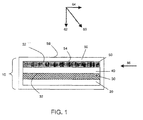
- FIG. 1 a general embodiment of an electrochemical cell can include a cathode, an anode, and an electrolyte layer in electrochemical communication with the cathode and the anode.
- the cell also may comprise a containment structure. The components may be assembled, in some cases, such that the electrolyte is placed between the cathode and anode in a stacked configuration.
- FIG. 1 illustrates an electrochemical cell of the invention.
- cell 10 includes a cathode 30 that can be formed on a substantially planar surface of substrate 20.
- cathode and substrate in FIG. 1 are shown as having a planar configuration, other embodiments may include non-planar configurations, as will be discussed in more detail later.
- the cathode may comprise a variety of cathode active materials.
- cathode active material refers to any electrochemically active species associated with the cathode.
- the cathode may comprise a sulfur-containing material, wherein sulfur is the cathode active material.
- cathode 30 comprises at least one active surface (e.g., surface 32).
- active surface is used to describe a surface of an electrode that is in physical contact with the electrolyte and at which electrochemical reactions may take place.
- An electrolyte 40 e.g., comprising a porous separator material
- electrolyte 40 may comprise a non-solid electrolyte, which may or may not be incorporated with a porous separator.
- non-solid is used to refer to materials that are unable to withstand a static shear stress, and when a shear stress is applied, the non-solid experiences a continuing and permanent distortion. Examples of non-solids include, for example, liquids, deformable gels, and the like.
- An anode layer 50 can be formed adjacent electrolyte 40 and may be in electrical communication with the cathode 30.
- the cell may also include, in some embodiments, containment structure 56.
- the anode may comprise a variety of anode active materials.
- anode active material refers to any electrochemically active species associated with the anode.
- the anode may comprise a lithium-containing material, wherein lithium is the anode active material.
- anode 50 comprises at least one active surface (e.g., surface 52).
- the anode 50 may also be formed on an electrolyte layer positioned on cathode 30 via electrolyte 40.
- orientation of the components can be varied, and it should be understood that there are other embodiments in which the orientation of the layers is varied such that, for example, the anode layer or the electrolyte layer is first formed on the substrate.
- additional layers such as a multi-layer structure that protects an electroactive material (e.g., an electrode) from the electrolyte, may be present, as described in more detail in U.S. Patent Application No. 11/400,781, filed April 06, 2006 , entitled, "Rechargeable Lithium/Water, Lithium/Air Batteries" to Affinito et al., which is incorporated herein by reference in its entirety.
- a typical electrochemical cell also would include, of course, current collectors, external circuitry, housing structure, and the like. Those of ordinary skill in the art are well aware of the many arrangements that can be utilized with the general schematic arrangement as shown in the figures and described herein.
- FIG. 1 illustrates an electrolytic cell arranged in a stacked configuration
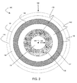
- FIG. 2 illustrates a cross-sectional view of an electrochemical cell arranged as a cylinder.
- cell 100 includes an electrode 130, an electrolyte 140, and electrode 150.
- electrode 130 may comprise an anode while electrode 150 may comprise a cathode, while in other embodiments, their order may be reversed.
- the cell may contain a core 170, which may be solid, hollow, or contain a channel or channels.
- Cell 100 also includes active surfaces 132 and 152.
- the cell may also include, in some embodiments, containment structure 156.
- electrode 130 is formed on core 170
- electrolyte 140 is formed on electrode 130
- electrode 150 is formed on electrolyte 140.
- electrode 130 may be proximate core 170
- electrolyte 140 may be proximate electrode 130
- electrode 150 may be proximate electrolyte 140, optionally including one or more intervening sections of material between components.
- electrode 130 may at least partially surround core 170
- electrolyte 140 may at least partially surround electrode 130
- electrode 150 may at least partially surround electrolyte 140.
- a first entity is "at least partially surrounded" by a second entity if a closed loop can be drawn around the first entity through only the second entity, and does not imply that the first entity is necessarily completely encapsulated by the second entity.
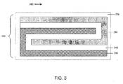
- the electrochemical cell is in the shape of a folded stack.
- the cell 200 illustrated in FIG. 3 comprises electrolyte 240 separating anode 230 and cathode 250.
- the Electrochemical cell in FIG. 3 comprises an electrolyte including three folded planes parallel to arrow 260.
- electrochemical cells may comprise electrolytes including any number of folded planes parallel to arrow 260.
- the cell may also include, in some embodiments, containment structure 256.
- containment structure 256 In addition to the shapes illustrated in FIGS.
- the electrochemical cells described herein may be of any other shape including, but not limited to, prisms (e.g., triangular prisms, rectangular prisms, etc.), "Swiss-rolls," non-planar stacks, etc. Additional configurations are described in U.S. Patent Application No. 11/400,025, filed April 06, 2006 , entitled, "Electrode Protection in both Aqueous and Non-Aqueous Electrochemical Cells, including Rechargeable Lithium Batteries,” to Affinito et al., which is incorporated herein by reference in its entirety.
- the present invention relates to electrochemical devices in which the application of force is used to enhance the performance of the device.
- the force comprises an anisotropic force with a component normal to the active surface of the anode.
- the force may comprise an anisotropic force with a component normal to the surface at the point at which the force is applied.
- a force may be applied in the direction of arrow 60.
- Arrow 62 illustrates the component of the force that is normal to active surface 52 of anode 50.
- the force may comprise an anisotropic force with a component normal to a plane that is tangent to the curved surface at the point at which the force is applied.
- a force may be applied to an external surface of the cell in the direction of, for example, arrow 180.
- the force may be applied from the interior of the cylindrical cell, for example, in the direction of arrow 182.
- an anisotropic force with a component normal to the active surface of the anode is applied during at least one period of time during charge and/or discharge of the electrochemical cell.
- the force may be applied continuously, over one period of time, or over multiple periods of time that may vary in duration and/or frequency.
- the anisotropic force may be applied, in some cases, at one or more pre-determined locations, optionally distributed over the active surface of the anode. In some embodiments, the anisotropic force is applied uniformly over the active surface of the anode.
- anisotropic force is given its ordinary meaning in the art and means a force that is not equal in all directions.
- a force equal in all directions is, for example, internal pressure of a fluid or material within the fluid or material, such as internal gas pressure of an object.
- forces not equal in all directions include forces directed in a particular direction, such as the force on a table applied by an object on the table via gravity.
- Another example of an anisotropic force includes a force applied by a band arranged around a perimeter of an object.
- a rubber band or turnbuckle can apply forces around a perimeter of an object around which it is wrapped.
- the band may not apply any direct force on any part of the exterior surface of the object not in contact with the band.
- the band when the band is expanded along a first axis to a greater extent than a second axis, the band can apply a larger force in the direction parallel to the first axis than the force applied parallel to the second axis.
- a force with a "component normal" to a surface for example an active surface of an anode, is given its ordinary meaning as would be understood by those of ordinary skill in the art and includes, for example, a force which at least in part exerts itself in a direction substantially perpendicular to the surface.
- a force which at least in part exerts itself in a direction substantially perpendicular to the surface For example, in the case of a horizontal table with an object resting on the table and affected only by gravity, the object exerts a force essentially completely normal to the surface of the table. If the object is also urged laterally across the horizontal table surface, then it exerts a force on the table which, while not completely perpendicular to the horizontal surface, includes a component normal to the table surface.
- the anisotropic force can be applied such that the magnitude of the force is substantially equal in all directions within a plane defining a cross-section of the electrochemical cell, but the magnitude of the forces in out-of-plane directions is substantially unequal to the magnitudes ofthe in-plane forces.
- a cylindrical band may be positioned around the exterior of cell 100 such that forces (e.g., force 180) are applied to the cell oriented toward the cell's central axis (indicated by point 190 and extending into and out of the surface of the cross-sectional schematic diagram).
- the magnitudes of the forces oriented toward the central axis of the cell are different (e.g., greater than) the magnitudes of the forces applied in out of plane directions (e.g., parallel to central axis 190).
- cells of the invention are constructed and arranged to apply, during at least one period of time during charge and/or discharge of the cell, an anisotropic force with a component normal to the active surface of the anode.
- an anisotropic force with a component normal to the active surface of the anode.
- the cell may be formed as part of a container which applies such a force by virtue of a "load” applied during or after assembly of the cell, or applied during use of the cell as a result of expansion and/or contraction of one or more portions of the cell itself.
- the magnitude of the applied force is, in some embodiments, large enough to enhance the performance of the electrolytic cell.
- the anode active surface and the anisotropic force may be, in some instances, together selected such that the anisotropic force affects surface morphology of the anode active surface to inhibit increase in anode active surface area through charge and discharge and wherein, in the absence of the anisotropic force but under otherwise essentially identical conditions, the anode active surface area is increased to a greater extent through charge and discharge cycles.
- Essentially identical conditions in this context, means conditions that are similar or identical other than the application and/or magnitude of the force. For example, otherwise identical conditions may mean a cell that is identical, but where it is not constructed (e.g., by brackets or other connections) to apply the anisotropic force on the subject cell.
- the anode active surface and anisotropic force can be selected together, to achieve results described herein, easily by those of ordinary skill in the art. For example, where the anode active surface is relatively softer, the component of the force normal to the anode active surface may be selected to be lower. Where the anode active surface is harder, the component of the force normal to the active surface may be greater.
- Those of ordinary skill in the art can easily select anode materials, alloys, mixtures, etc. with known or predictable properties, or readily test the hardness or softness of such surfaces, and readily select cell construction techniques and arrangements to provide appropriate forces to achieve what is described herein.
- Simple testing can be done, for example by arranging a series of active materials, each with a series of forces applied normal (or with a component normal) to the active surface, to determine the morphological effect of the force on the surface without cell cycling (for prediction of the selected combination during cell cycling) or with cell cycling with observation of a result relevant to the selection.
- an anisotropic force with a component normal to the active surface ofthe anode is applied, during at least one period of time during charge and/or discharge of the cell, to an extent effective to inhibit an increase in surface area of the anode active surface relative to an increase in surface area absent the anisotropic force.
- the component of the anisotropic force normal to the anode active surface may, for example, define a pressure of at least about 4.9, at least about 9.8, at least about 24.5, at least about 49, at least about 98, at least about 117.6, or at least about 147 Newtons per square centimeter.
- the component of the anisotropic force normal to the anode active surface may, for example, define a pressure of less than about 196, less than about 14.7, less than about 117.6, less than about 98, less than about 49, less than about 24.5, or less than about 9.8 Newtons per square centimeter. In some cases, the component of the anisotropic force normal to the anode active surface is may define a pressure of between about 4.9 and about 147 Newtons per square centimeter, between about 49 and about 117.6 Newtons per square centimeter, or between about 68.6 and about 98 Newtons per square centimeter.
- forces and pressures are generally described herein in units ofNewtons and Newtons per unit area, respectively, forces and pressures can also be expressed in units of kilograms-force and kilograms-force per unit area, respectively.
- forces and pressures can also be expressed in units of kilograms-force and kilograms-force per unit area, respectively.
- kilogram-force-based units One or ordinary skill in the art will be familiar with kilogram-force-based units, and will understand that 1 kilogram-force is equivalent to about 9.8 Newtons.
- one or more forces applied to the cell have a component that is not normal to an active surface of an anode.
- force 60 is not normal to anode active surface 52
- force 60 includes component 64, which is substantially parallel to anode active surface 52.
- a force 66 which is substantially parallel to anode active surface 52, could be applied to the cell in some cases.
- the sum of the components of all applied anisotropic forces in a direction normal to the anode active surface is larger than any sum of components in a direction that is non-normal to the anode active surface.
- the sum of the components of all applied anisotropic forces in a direction normal to the anode active surface is at least about 5%, at least about 10%, at least about 20%, at least about 35%, at least about 50%, at least about 75%, at least about 90%, at least about 95%, at least about 99%, or at least about 99.9% larger than any sum of components in a direction that is parallel to the anode active surface.
- the cathode and anode have yield stresses, wherein the effective yield stress of one of the cathode and anode is greater than the yield stress of the other, such that an anisotropic force applied normal to the surface of one of the active surface of the anode and the active surface of the cathode causes the surface morphology of one of the cathode and the anode to be affected.
- the component of the anisotropic force normal to the anode active surface is between about 20% and about 200% of the yield stress of the anode material, between about 50% and about 120% of the yield stress of the anode material, or between about 80% and about 100% of the yield stress of the anode material.
- the anisotropic force described herein may be applied using any method known in the art.
- the force may be applied using compression springs.
- electrolytic cell 10 may be situated in an optional enclosed containment structure 56 with one or more compression springs situated between surface 54 and the adjacent wall of the containment structure to produce a force with a component in the direction of arrow 62.
- the force may be applied by situating one or more compression springs outside the containment structure such that the spring is located between an outside surface 58 of the containment structure and another surface (e.g., a tabletop, the inside surface of another containment structure, an adjacent cell, etc.).
- Forces may be applied using other elements (either inside or outside a containment structure) including, but not limited to Belleville washers, machine screws, pneumatic devices, and/or weights, among others.
- one or more cells e.g., a stack of cells
- a device e.g., a machine screw, a spring, etc.
- the cells may be compressed between the plates upon rotating the screw.
- one or more wedges may be displaced between a surface of the cell (or the containment structure surrounding the cell) and a fixed surface (e.g., a tabletop, the inside surface of another containment structure, an adjacent cell, etc.).
- the anisotropic force may be applied by driving the wedge between the cell and the adjacent fixed surface through the application of force on the wedge (e.g., by turning a machine screw).
- cells may be pre-compressed before they are inserted into containment structures, and, upon being inserted to the containment structure, they may expand to produce a net force on the cell.
- the cylindrical cell of FIG. 2 could be pre-compressed and inserted within containment structure 156.
- the containment structure could then provide a force to the outside surface of the cylindrical cell upon expansion of the cell.
- the containment structures may comprise a relatively high strength (e.g., at least about 100 MPa, at least about 200 MPa, at least about 500 MPa, or at least about 1 GPa).
- the containment structure may comprise a relatively high elastic modulus (e.g., at least about 10 GPa, at least about 25 GPa, at least about 50 GPa, or at least about 100 GPa).
- the containment structure may comprise, for example, aluminum, titanium, or any other suitable material.
- any of the forces described herein may be applied to a plurality of electrochemical cells in a stack.
- a "stack" of electrochemical cells is used to refer to a configuration in which multiple cells are arranged in an essentially cell-repetitive pattern, e.g., positioned on top of one another.
- the cells may be positioned such that at least one surface of each cell in the stack is substantially parallel to at least one surface of every other cell in the stack, e.g., where a surface of one particular component (e.g., the anode) of one cell is substantially parallel to the same surface of the same component of every other cell.
- FIG. 8 includes a schematic illustration of a stack of electrochemical cells 10.
- the cells may be in direct contact with one another, while in some instances one or more spacers may be positioned between the cells in a stack.
- the stack of electrochemical cells may comprise any number of cells (e.g., at least 2, at least 3, at least 5, at least 10, at least 25, at least 100 cells, or more).
- a constricting element may surround at least a portion of a cell or a stack of cells.
- the constricting element may be constructed and arranged, in some cases, to apply an anisotropic force with a component normal to at least one anode active surface within the cell or stack of cells defining a pressure of at least about 4.9, at least about 9.8, at least about 24.5, at least about 49, at least about 98, at least about 117.6, at least about 147, less than about 196, less than about 147, less than about 117.6, less than about 98, less than about 49, less than about 24.5, less than about 9.8, between about 4.9 and about 147, between about 49 and about 117.6, or between about 68.6 and about 98 Newtons per square centimeter.
- the constricting element may comprise a band (e.g., a rubber band, a turnbuckle band, etc.).
- a constricting element 320 surrounds a stack of cells 10.
- a band can be affixed to the cell or stack of cells by, for example adhesive, staples, clamps, a turn-buckle, or any other suitable method,
- the band comprises a turnbuckle band (e.g., a Kevlar turnbuckle band), and force is applied by tightening the band and securing the turnbuckle.
- the band is a continuous elastic band.
- a force may be applied via the elastic constriction of the band.
- a band can be installed by cooling the band material below its martensitic transformation temperature and plastically deforming (e.g., via stretching) the band to fit over the cell or stack of cells, Upon returning to operating temperature, the band could then shrink to its preformed shape, by which the band could apply a force.
- the constricting element may comprise any material with an amount of elasticity necessary to produce the desired force.
- a solid band of elastic material can be sized such that it provides required external pressure upon being applied to the outer surface of the cell or cells and relaxing.
- the constricting element may comprise a polymeric material.
- the constricting element may comprise, for example, Desmopan ® 392 (a polyester urethane, made by Bayer MaterialScience, Leverkusen, Germany), Estane ® (an engineered polymer made by The Lubrizol Corporation, Wickliffe, Ohio), Kevlar ® (a synthetic fiber made by DuPont, Wilmington, Delaware), among others.
- the constricting element may comprise a shape memory alloy (e.g., nitinol (NiTi)), which may expand and contract upon varying the temperature to which the material is exposed.
- the constricting element can comprise shrink wrap tubing such as, for example, polyester film and/or fabric.
- the mass density of the elements used to apply a force to a cell or a stack of cells is relatively low. By using elements with relatively low mass densities, the energy density and specific energy of the cell or stack of cells may remain relatively high, In some embodiments the mass density of the article(s) used to apply a force to a cell or a stack of cells is less than about 10 g/cm 3 , less than about 5 g/cm 3 , less than about 3 g/cm 3 , less than about 1 g/cm 3 , less than about 0.5 g/cm 3 , less than about 0.1 g/cm 3 , between about 0.1 g/cm 3 and about 10 g/cm 3 , between about 0.1 g/cm 3 and about 5 g/cm 3 , or between about 0.1 g/cm 3 and about 3 g/cm 3 .
- pressure distribution components may be included between a cell and another cell or between a cell and a constricting element. Such pressure distribution components can allow for a uniform force to be applied throughout the cell or stack of cells.
- the pressure distribution components comprise an end cap.
- the end caps' shape can be selected so as to convert the linear forces applied by the band to a uniform force across, for example, the active area of an anode.
- optional caps 310 may be placed between the ends of the stack and the band.
- the caps shown in FIG. 8 include rounded ends, which may, for example, be used to reduce separation of the band from the stack at corners and edges and enhance the uniformity of the distribution of force.
- the caps can comprise any suitable material including, for example, metal (e.g., aluminum), carbon fiber, plastics, etc.
- the end caps are relatively easy to form or machine into complex shapes.
- the mass density of the end caps may be relatively low.
- the end caps may have a mass density of less than about 5 g/cm 3 , less than about 3 g / cm 3 , less than about 1 g/cm 3 , less than about 0.5 g/cm 3 , less than about 0.1 g/cm 3 , between about 0.1 g/cm 3 and about 10 g/cm 3 , between about 0.1 g/cm 3 and about 5 g/cm 3 , or between about 0.1 g/cm 3 and about 3 g/cm 3 .
- the end caps may comprise any suitable stiffness.
- the stiffness of the end caps may be higher than 50 GPa, in some embodiments.
- a pressure distribution component comprises a spacer positioned between two cells.
- Inter-cell spacers can serve to reduce stress concentrations that may arise, for example, due to geometrical manufacturing variations of individual cells. For example, the flatness of the cells may vary from cell to cell. As another example, opposing sides of one or more cells may not be perfectly parallel in some cases.
- optional spacers 330 have been inserted between cells 10.
- Spacers can comprise any suitable material including, for example, metal (e.g., aluminum), metal foams, carbon composites, carbon foams, plastics, etc. In some embodiments, the spacers are relatively easy to form or machine into complex shapes.
- a spacer can also have any suitable thickness.
- a spacer may have an average thickness of less than about 10 mm, less than about 5 mm, less than about 1 mm, less than about 500 microns, or less than about 250 microns.
- a spacer can be between about 100 microns and about 10 mm, between about 100 microns and about 1 mm, between about 250 microns and about 10 mm, between about 250 microns and about mm, or between about 500 microns and about 2 mm.
- Opposing faces of the spacer(s) may be highly parallel, in some embodiments.
- the variation of the distance between a first surface of a spacer in contact with a first cell and a second surface of the spacer in contact with a second cell, as measured substantially parallel to a vector drawn from the center of mass of the first cell to the center of mass of the second cell (e.g., as in line 340 in FIG. 8 ), across the width of the spacer is less than about 1 mm, less than about 500 microns, less than about 100 microns, less than about 50 microns, less than about 25 microns, less than about 10 microns, or less than about I micron.
- the mass density of the spacer(s) in a stack of cells can be relatively low, in some instances.
- the spacers may have a mass density of less than about 5 g/cm 3 , less than about 2 g/cm 3 , less than about 1 g/cm 3 , less than about 0.5 g/cm 3 , less than about 0.1 g/cm 3 , between about 0.1 g/cm 3 and about 10 g/cm 3 , between about 0.1 g/cm 3 and about 5 g/cm 3 , or between about 0.1 g/cm 3 and about 2 g/cm 3 .
- the end caps may comprise a relatively high stiffness.
- the stiffness of the spacer(s) may be higher than 10 GPa, in some embodiments.
- end cap(s) or spacer(s) One of ordinary skill in the art will be able to perform experiments to determine appropriate sizes, shapes, and materials of construction for the end cap(s) or spacer(s) to be used with a cell or stack of cells. For example, if the end cap or spacer material is sufficiently stiff, a simple geometric optimization of the shape may be sufficient to determine their properties. In other cases, more complex stress/strain calculations may be required to ensure the pressure distribution is substantially uniform after the end caps and/or spacers have equilibrated to their final deformed shape.
- constriction elements are not limited to flat cell geometries.
- a constriction element may be used to apply a force to a cylindrical electrochemical cell or a prismatic electrochemical cell (e.g., a triangular prism, a rectangular prism, etc.).
- optional constricting element 181 can be positioned around the cell such that it surrounds at least a portion of the outside of the electrochemical cell.
- the constriction element may be used to apply a force to the outermost surface of the electrochemical cell (e.g., surface 182 or surface 184 in FIG. 2 ).
- constriction elements may be used as constriction elements in cylindrical cells, prismatic cells, or other such cells.
- one or more wraps of the same or different winding material may be positioned on the outside surface of the cell.
- the winding material comprises relatively high strength.
- the winding material may also comprise a relatively high elastic modulus.
- shrink wrap tubing such as polyester film and fabric.
- the constriction element comprises an elastic material properly sized to provide required external pressure after it relaxes on the outer surface of the cell.
- the cell may comprise an expanding element (e.g., an expanding mandrel) within an inner volume of the cell such (e.g., hollow core 170 in FIG. 2 ).
- the expanding element can be constructed and arranged to apply a force radiating outward from the inner volume of the electrochemical cell, such as, for example, in the direction of arrow 182 in FIG. 2 .
- the expanding element and the constricting element can be constructed and arranged such that the force within the boundaries of the electrochemical cell deviates by less than about 30%, less than about 20%, less than about 10%, or less than about 5% of the median force within the boundaries electrochemical cell.
- such a distribution of forces can be achieved, for example, by selecting constricting and expanding elements such that substantially equal internal and external forces per unit area are applied to the cell.
- external pressure application can be combined with complimentary winding mechanics to achieve a radial pressure distribution that is within acceptable bounds.
- proper surface nip winding e.g., using a nip roller
- the contracting element may be constructed and arranged to produce a force of 0 Newtons/cm 2 at the inner diameter and 78.5 Newtons/cm 2 at the outer diameter.
- the superposition of these two distributions can result in a mean pressure application of 98 Newtons/cm 2 with a variation of ⁇ 19.6 Newtons/cm 2 .
- the total volumes of the pressure distribution elements(s) e.g., end caps, spacers, etc.
- the element(s) used to apply a force to the cell or stack of cells e.g., bands, mandrels, etc.
- the energy density of the assembly may be kept relatively high.
- the sum of the volumes of the pressure distribution element(s) and the element(s) used to apply a force to a cell or stack of cells comprises less than about 10%, less than about 5%, less than about 2%, less than about 1%, less than about 0.5%, less than about 0.1%, between about 0.1% and about 10%, between about 0.1% and about 5%, between about 0.1% and about 2%, or between about 0.1% and about 1% of the volume of the cell or stack of cells.
- the cells described herein may change size (e.g., swell) during charge and discharge.
- this selection may be analogous to selecting a system with a low effective spring constant (e.g., a "soft" spring).
- a spring with a relatively low spring constant may produce an anisotropic force that is more constant during cell cycling than the force produced by a spring with a relatively high spring constant.
- a band with a relatively high elasticity may produce an anisotropic force that is more constant during cell cycling than the force produced by a band with a relatively low elasticity.
- the use of soft screws e.g., brass, polymer, etc.
- a machine screw may be selected to cover a desired range of compression, but the screw itself may be soft.
- the electrolytic cells of the present invention are placed in containment structures, and at least a portion of an anisotropic force with a component normal to the active surface of the anode is produced due to the expansion of the electrolytic cell relative to the containment structure.
- the containment structure is sufficiently rigid such that it does not deform during the expansion of the electrolytic cell, resulting in a force applied on the cell.
- the electrolytic cell may swell as the result of a variety of phenomena. For example, in some cases, the electrolytic cell may undergo thermal expansion. In some embodiments, the electrolytic cell may swell due to charge and/or discharge of the cell.
- a partially discharged cell may be placed in a containment structure. Upon charging the partially discharged cell, the cell may swell. This expansion may be limited by the dimensions of the containment structure, resulting in the application of an anisotropic force.
- the cell may swell due to the adsorption of a liquid into porous components of the electrolytic cell,
- a dry porous electrolytic cell may be placed within a containment structure. The dry porous electrolytic cell may then be soaked (e.g., with a liquid electrolyte).
- the properties of the electrolyte (e.g., surface tension) and the electrolytic cell (e.g., size of the porous cavities) may be selected such that, when the electrolytic cell is wetted by the electrolyte, a desirable level of capillary pressure is generated.
- the electrode stack will swell, thus generating an anisotropic force. At equilibrium, the anisotropic force exerted by the containment structure on the electrolytic cell will be equal to the force resulting from the capillary pressure.
- Containment structures described herein may comprise a variety of shapes including, but not limited to, cylinders, prisms (e.g., triangular prisms, rectangular prisms, etc.), cubes, or any other shape.
- the shape of the containment structure is chosen such that the walls of the containment structure are parallel to the outer surfaces of the electrolytic cell.
- the containment structure may comprise a cylinder, which can be used, for example, to surround and contain a cylindrical electrolytic cell.
- the containment structure may comprise a prism surrounding a similarly shaped prismatic electrolytic cell.
- the invention relates to the discovery that the application of a force as described herein may allow for the use of smaller amounts of anode active material (e.g., Lithium) and/or electrolyte within an electrochemical cell, relative to the amounts used in essentially identical cells in which the force is not applied.
- anode active material e.g., lithium metal
- anode active material may be, in some cases, redeposited unevenly on an anode during charge-discharge cycles of the cell, forming a rough surface. In some cases, this may lead to an increase in the rates of one or more undesired reactions involving the anode metal.
- the application of force as described herein may reduce and/or prevent depletion of active materials such that the inclusion of large amounts of anode active material and/or electrolyte within the electrochemical cell may not be necessary.
- the force may be applied to a cell prior to use of the cell, or in an early stage in the lifetime ofthe cell (e.g., less than five charge-discharge cycles), such that little or substantially no depletion of active material may occur upon charging or discharging of the cell.
- relatively small amounts of anode active material may be used to fabricate cells and devices as described herein.
- the invention relates to devices comprising an electrochemical cell having been charged and discharged less than five times in its lifetime, wherein the cell comprises an anode, a cathode, and an electrolyte, wherein the anode comprises no more than five times the amount of anode active material which can be ionized during one full discharge cycle of the cell. In some cases, the anode comprises no more than four, three, two, or 1.5 times the amount of lithium which can be ionized during one full discharge cycle of the cell.
- the present invention relates to devices comprising an electrochemical cell, wherein the cell comprises an anode active material, a cathode active material, and an electrolyte, wherein the ratio of the amount of anode active material in the anode to the amount of cathode active material in the cathode is less than about 5:1, less than about 3:1, less than about 2:1, or less than about 1.5:1 on a molar basis.
- a cell may comprise lithium as an anode active material and sulfur as an cathode active material, wherein the molar ratio Li:S is less than about 5:1.
- the molar ratio of lithium to sulfur, Li:S is less than about 3:1, less than about 2:1, or less than about 1.5:1.
- the ratio of anode active material (e.g., lithium) to cathode active material by weight may be less than 2:1, less than about 1.5:1, less than about 1.25:1, or less than about 1.1:1.
- a cell may comprise lithium as the anode active material and sulfur as the cathode active material, wherein the ratio Li:S by weight is less than about 2:1, less than about 1.5:1, less than about 1.25:1, or less than about 1.1:1.
- anode active material and/or electrolyte material may advantageously allow for electrochemical cells, or portions thereof, having decreased thickness.
- the anode layer and the electrolyte layer together have a maximum thickness of 500 microns. In some cases, the anode layer and the electrolyte layer together have a maximum thickness of 400 microns, 300 microns, 200 microns, or, in some cases, 100 microns.
- the application of force may result in improved capacity after repeated cycling of the electrochemical cell.
- the cell after alternatively discharging and charging the cell three times, the cell exhibits at least about 50%, at least about 80%, at least about 90%, or at least about 95% of the cell's initial capacity at the end of the third cycle.
- the cell after alternatively discharging and charging the cell ten times, the cell exhibits at least about 50%, at least about 80%, at least about 90%, or at least about 95% of the cell's initial capacity at the end of the tenth cycle.
- the cell after alternatively discharging and charging the cell twenty-five times, the cell exhibits at least about 50%, at least about 80%, at least about 90%, or at least about 95% of the cell's initial capacity at the end of the twenty-fifth cycle.
- Suitable electroactive materials for use as cathode active materials in the cathode of the electrochemical cells of the invention include, but are not limited to, electroactive transition metal chalcogenides, electroactive conductive polymers, sulfur, carbon and/or combinations thereof As used herein, the term "chalcogenides" pertains to compounds that contain one or more of the elements of oxygen, sulfur, and selenium.
- transition metal chalcogenides include, but are not limited to, the electroactive oxides, sulfides, and selenides of transition metals selected from the group consisting of Mn, V, Cr, Ti, Fe, Co, Ni, Cu, Y, Zr, Nb, Mo, Ru, Rh, Pd, Ag, Hf, Ta, W, Re, Os, and Ir.
- the transition metal chalcogenide is selected from the group consisting of the electroactive oxides of nickel, manganese, cobalt, and vanadium, and the electroactive sulfides of iron.
- a cathode includes one or more of the following materials: manganese dioxide, iodine, silver chromate, silver oxide and vanadium pentoxide, copper oxide, copper oxyphosphate, lead sulfide, copper sulfide, iron sulfide, lead bismuthate, bismuth trioxide, cobalt dioxide, copper chloride, manganese dioxide, and carbon.
- the cathode active layer comprises an electroactive conductive polymer.
- suitable electroactive conductive polymers include, but are not limited to, electroactive and electronically conductive polymers selected from the group consisting of polypyrroles, polyanilines, polyphenylenes, polythiophenes, and polyacetylenes. Examples of conductive polymers include polypyrroles, polyanilines, and polyacetylenes.
- electroactive materials for use as cathode active materials in Electrochemical cells described herein include electroactive sulfur-containing materials.
- Electroactive sulfur-containing materials as used herein, relates to cathode active materials which comprise the element sulfur in any form, wherein the electrochemical activity involves the oxidation or reduction of sulfur atoms or moieties.
- the nature of the electroactive sulfur-containing materials useful in the practice of this invention may vary widely, as known in the art.
- the electroactive sulfur-containing material comprises elemental sulfur.
- the electroactive sulfur-containing material comprises a mixture of elemental sulfur and a sulfur-containing polymer.
- suitable electroactive sulfur-containing materials may include, but are not limited to, elemental sulfur and organic materials comprising sulfur atoms and carbon atoms, which may or may not be polymeric.
- Suitable organic materials include those further comprising heteroatoms, conductive polymer segments, composites, and conductive polymers.
- the cathode may comprise one or more binder materials (e.g., polymers, porous silica sol-gel, etc.).
- binder materials e.g., polymers, porous silica sol-gel, etc.
- sulfur-containing polymers examples include those described in: U.S. Patent Nos. 5,601,947 and 5,690,702 to Skotheim et al. ; U.S. Patent Nos. 5,529,860 and 6,117,590 to Skotheim et al. ; U.S. Patent No. 6,201,100 issued Mar. 13, 2001, to Gorkovenko et al . of the common assignee, and PCT Publication No. WO 99/33130 .
- Other suitable electroactive sulfur-containing materials comprising polysulfide linkages are described in U.S. Patent No. 5,441,831 to Skotheim et al. ; U.S. Patent No. 4,664,991 to Perichaud et al.
- electroactive sulfur-containing materials include those comprising disulfide groups as described, for example in, U.S. Patent No. 4,739,018 to Armand et al. ; U.S. Patent Nos. 4,833,048 and 4,917,974, both to De Jonghe et al. ; U.S. Patent Nos. 5,162,175 and 5,516,598, both to Visco et al. ; and U.S. Patent No. 5,324,599 to Oyama et al .
- an electroactive sulfur-containing material of a cathode active layer comprises greater than 50% by weight of sulfur. In another embodiment, the electroactive sulfur-containing material comprises greater than 75% by weight of sulfur. In yet another embodiment, the electroactive sulfur-containing material comprises greater than 90% by weight of sulfur.
- the cathode active layers of the present invention may comprise from about 20 to 100% by weight of electroactive cathode materials (e.g., as measured after an appropriate amount of solvent has been removed from the cathode active layer and/or after the layer has been appropriately cured).
- the amount of electroactive sulfur-containing material in the cathode active layer is in the range of 5-30% by weight of the cathode active layer. In another embodiment, the amount of electroactive sulfur-containing material in the cathode active layer is in the range of 20% to 90% by weight of the cathode active layer.
- suitable liquid media e.g., solvents
- suitable liquid media for the preparation of cathodes (as well as other components of cells described herein) include aqueous liquids, non-aqueous liquids, and mixtures thereof.
- liquids such as, for example, water, methanol, ethanol, isopropanol, propanol, butanol, tetrahydrofuran, dimethoxyethane, acetone, toluene, xylene, acetonitrile, cyclohexane, and mixtures thereof can be used.
- suitable solvents can also be used as needed.
- Positive electrode layers may be prepared by methods known in the art.
- one suitable method comprises the steps of: (a) dispersing or suspending in a liquid medium the electroactive sulfur-containing material, as described herein; (b) optionally adding to the mixture of step (a) a conductive filler and/or binder; (c) mixing the composition resulting from step (b) to disperse the electroactive sulfur-containing material; (d) casting the composition resulting from step (c) onto a suitable substrate; and (e) removing some or all of the liquid from the composition resulting from step (d) to provide the cathode active layer.
- the use of a cathode that is resistant to compression can enhance the performance of the cell relative to cells in which the cathode is significantly compressible.
- the use of elastic, relatively highly compressible cathodes may result in the evacuation of liquid electrolyte during the application of the anisotropic force. The evacuation of liquid electrolyte from the cathode may result in decreased power output during the operation of the electrolytic cell.
- a decrease in power output from the electrolytic cell may be observed even when the anisotropic force is relatively small (e.g., an anisotropic force with a component normal to an active surface of the anode defining a pressure of about 68.6 Newtons/cm 2 ) or when the anisotropic force is of another magnitude, for example, as noted above with reference to limits and ranges of the component of the anisotropic force normal to the anode active surface.
- the degree of compressibility can be correlated to a change in porosity, i.e., change in void volume of the cathode, during application of a compressive force.
- the porosity of the cathode may be decreased during operation of the cell by less than 10%, less than 6%, less than 4%, less than 2%, less than 1%, less than 0.5%, less than 0.1%, or lower. That is, during use of the cell, a compressive force experienced by the cathode may reduce the total void volume, or total volume otherwise accessible by the electrolyte, by percentages noted above, where the cathode is fabricated to provide suitable resistance to compression.
- the stiffness of the cathode may be enhanced using a variety of methods.
- the type of electrolyte and the size of the pores in the cathode may be together selected such that the resulting capillary forces produced by the interaction of the electrolyte and the cathode pores resist the deformation of the cathode. This effect may be particularly useful, for example, in small electrolytic cells.
- the stiffness of the cathode may be enhanced by incorporating reinforcement fibers (e.g., to connect carbon particles) into the cathode.
- binder may be incorporated into the cathode to provide rigidity.
- an inherently rigid cathode may be produced by infusing active material (e.g., reticulated Ni foam) into a thin and light superstructure.
- Suitable electroactive materials for use as anode active materials in the anode of the electrochemical cells described herein include, but are not limited to, lithium metal such as lithium foil and lithium deposited onto a conductive substrate, and lithium alloys (e.g., lithium-aluminum alloys and lithium-tin alloys). While these are preferred negative electrode materials, the current collectors may also be used with other cell chemistries.
- the anode may comprise one or more binder materials (e.g., polymers, etc.).
- Methods for depositing a negative electrode material e.g., an alkali metal anode such as lithium
- a negative electrode material e.g., an alkali metal anode such as lithium
- Methods for depositing a negative electrode material onto a substrate may include methods such as thermal evaporation, sputtering, jet vapor deposition, and laser ablation.
- the anode comprises a lithium foil, or a lithium foil and a substrate, these can be laminated together by a lamination process as known in the art to form an anode.
- an electroactive lithium-containing material of an anode active layer comprises greater than 50% by weight of lithium. In another embodiment, the electroactive lithium-containing material of an anode active layer comprises greater than 75% by weight of lithium. In yet another embodiment, the electroactive lithium-containing material of an anode active layer comprises greater than 90% by weight of lithium.
- Positive and/or negative electrodes may optionally include one or more layers that interact favorably with a suitable electrolyte, such as those described in U.S. Provisional Application Serial No. 60/872,939, filed December 4, 2006 and entitled “Separation of Electrolytes,” by Mikhaylik et al., which is incorporated herein by reference in its entirety.
- the electrolytes used in electrochemical or battery cells can function as a medium for the storage and transport of ions, and in the special case of solid electrolytes and gel electrolytes, these materials may additionally function as a separator between the anode and the cathode.
- Any liquid, solid, or gel material capable of storing and transporting ions may be used, so long as the material facilitates the transport of ions (e.g., lithium ions) between the anode and the cathode.
- the electrolyte is electronically non-conductive to prevent short circuiting between the anode and the cathode.
- the electrolyte may comprise a non-solid electrolyte.
- the electrolyte can comprise one or more ionic electrolyte salts to provide ionic conductivity and one or more liquid electrolyte solvents, gel polymer materials, or polymer materials.
- Suitable non-aqueous electrolytes may include organic electrolytes comprising one or more materials selected from the group consisting of liquid electrolytes, gel polymer electrolytes, and solid polymer electrolytes. Examples of non-aqueous electrolytes for lithium batteries are described by Dominey in Lithium Batteries, New Materials, Developments and Perspectives, Chapter 4, pp. 137-165, Elsevier, Amsterdam (1994 ). Examples of gel polymer electrolytes and solid polymer electrolytes are described by Alamgir et al.
- non-aqueous liquid electrolyte solvents include, but are not limited to, non-aqueous organic solvents, such as, for example, N-methyl acetamide, acetonitrile, acetals, ketals, esters, carbonates, sulfones, sulfites, sulfolanes, aliphatic ethers, cyclic ethers, glymes, polyethers, phosphate esters, siloxanes, dioxolanes, N-alkylpyrrolidones, substituted forms of the foregoing, and blends thereof. Fluorinated derivatives of the foregoing are also useful as liquid electrolyte solvents.
- non-aqueous organic solvents such as, for example, N-methyl acetamide, acetonitrile, acetals, ketals, esters, carbonates, sulfones, sulfites, sulfolanes, aliphatic ethers, cycl
- aqueous solvents can be used as electrolytes for lithium cells.
- Aqueous solvents can include water, which can contain other components such as ionic salts.
- the electrolyte can include species such as lithium hydroxide, or other species rendering the electrolyte basic, so as to reduce the concentration of hydrogen ions in the electrolyte.
- Liquid electrolyte solvents can also be useful as plasticizers for gel polymer electrolytes, i.e., electrolytes comprising one or more polymers forming a semi-solid network.
- useful gel polymer electrolytes include, but are not limited to, those comprising one or more polymers selected from the group consisting of polyethylene oxides, polypropylene oxides, polyacrylonitriles, polysiloxanes, polyimides, polyphosphazenes, polyethers, sulfonated polyimides, perfluorinated membranes (NAFION resins), polydivinyl polyethylene glycols, polyethylene glycol diacrylates, polyethylene glycol dimethacrylates, derivatives of the foregoing, copolymers of the foregoing, crosslinked and network structures of the foregoing, and blends of the foregoing, and optionally, one or more plasticizers.
- a gel polymer electrolyte comprises between 10-20%, 20-40%, between 60-70%,
- one or more solid polymers can be used to form an electrolyte.
- useful solid polymer electrolytes include, but are not limited to, those comprising one or more polymers selected from the group consisting of polyethers, polyethylene oxides, polypropylene oxides, polyimides, polyphosphazenes, polyacrylonitriles, polysiloxanes, derivatives of the foregoing, copolymers of the foregoing, crosslinked and network structures of the foregoing, and blends of the foregoing.
- the electrolyte may further comprise one or more ionic electrolyte salts, also as known in the art, to increase the ionic conductivity.
- ionic electrolyte salts for use in the electrolytes of the present invention include, but are not limited to, LiSCN, LiBr, LiI, LiClO 4 LiAsF 6 , LiSO 3 CF 3 , LiSO 3 CH 3 , LiBF 4 , LiB(Ph) 4 , LiPF 6 , LiC(SO 2 CF 3 ) 3 , and LiN(SO 2 CF 3 ) 2 .
- electrolyte salts that may be useful include lithium polysulfides (Li 2 S x ), and lithium salts of organic ionic polysulfides (LiS x R) n , where x is an integer from 1 to 20, n is an integer from I to 3, and R is an organic group, and those disclosed in U.S. Patent No. 5,538,812 to Lee et al.
- electrochemical cells may further comprise a separator interposed between the cathode and anode.
- the separator may be a solid non-conductive or insulative material which separates or insulates the anode and the cathode from each other preventing short circuiting, and which permits the transport of ions between the anode and the cathode.
- the porous separator may be permeable to the electrolyte.
- the pores of the separator may be partially or substantially filled with electrolyte.
- Separators may be supplied as porous free standing films which are interleaved with the anodes and the cathodes during the fabrication of cells.
- the porous separator layer may be applied directly to the surface of one of the electrodes, for example, as described in PCT Publication No. WO 99/33125 to Carlson et al. and in U.S. Patent No. 5,194,341 to Bagley et al.
- separator materials are known in the art.
- suitable solid porous separator materials include, but are not limited to, polyolefins, such as, for example, polyethylenes (e.g., SETELATM made by Tonen Chemical Corp) and polypropylenes, glass fiber filter papers, and ceramic materials.
- the separator comprises a microporous polyethylene film.
- separators and separator materials suitable for use in this invention are those comprising a microporous xerogel layer, for example, a microporous pseudo-boehmite layer, which may be provided either as a free standing film or by a direct coating application on one of the electrodes, as described in U.S. Patent Nos. 6,153,337 and 6,306,545 by Carlson et al . of the common assignee. Solid electrolytes and gel electrolytes may also function as a separator in addition to their electrolyte function.
- an anisotropic force with a component normal to the active surface of an anode is applied to an electrochemical cell during at least one period of time during charge and/or discharge of the cell.
- the anode active surface and the anisotropic force were together selected such that the anisotropic force affected the surface morphology of the anode active surface to inhibit increase in anode active surface area through charge and discharge.
- the anode active surface area is increased to a greater extent through charge and discharge cycles.
- lithium metal >99.9% Li, 2 mil thick foil available from Chemetall-Foote Corp., Kings Mountain, NC
- the electrolyte comprised 13.2 parts of lithium bis (trifluoromethane sulfonyl) imide, (lithium imide available from 3M Corporation, St. Paul, MN), 1.1 parts lithium nitrate (available from Aldrich Chemical Company, Milwaukee, WI) in 1,3-dioxolane, with water content of less than 50 ppm.
- the porous separator used was 16 ⁇ m SETELA (a trademark for a polyolefin separator available from Tonen Chemical Corporation, Tokyo, Japan, and also available from Exxon Mobil Chemical Company, Films Division, Pittsford, NY).
- the above components were stacked into a layered structure of anode/separator/anode, with the liquid electrolyte filling the void areas of the separator to form prismatic cells with an electrode area of about 16 cm 2 .
- the cells were stored for 24 hours and placed between steel plates with compression springs.
- the cell was constructed and arranged to apply, during at least one period of time during charge and/or discharge of the cell, an anisotropic force with a component normal to the active surface of the anode.
- the anisotropic force defined a pressure of 98 Newtons/cm 2 .
- FIG. 4 includes an SEM micrograph of a lithium anode after the application of 98 Newtons/cm 2 over 30 cycles. The resulting anodes were compact had retained their original thickness and were composed primarily of lithium metal.
- Example 1 an electrochemical cell identical to the cell employed in Example 1 was charged and discharged.
- the electrochemical cell was charged and discharged in the absence of the anisotropic force.
- the conditions under which the cell was operated were essentially identical to those outlined in Example 1.
- FIG. 5 includes an SEM micrograph of a lithium anode after charge and discharge in the absence of an isotropic force.
- the resulting anodes were very porous, had more than doubled in thickness, and were composed primarily of decomposition products rather than metallic lithium.
- FIGS. 6A-D includes SEM micrographs of various deposited lithium metal anodes after 30 charge/discharge cycles.
- the anode in FIG. 6A was cycled in the absence of an anisotropic force, while the anodes in FIGS. 6B , C, and D were cycled with applied forces defining pressures of 49, 73.5, and 98 Newtons/cm 2 , respectively. From the micrographs, it can be seen that as the applied force was increased, the resulting lithium metal anode was thinner and less porous.
- FIGS. 7A-D includes SEM micrographs of various stripped lithium metal anodes after 30 charge/discharge cycles.
- the anode in FIG. 7A was cycled in the absence of an anisotropic force, while the anodes in FIGS. 7B , C, and D were cycled with applied forces of 49, 73.5, and 98 Newtons/cm 2 , respectively. Again, as the applied force was increased, the resulting lithium metal anode was thinner and less porous.
- a reference to "A and/or B,” when used in conjunction with open-ended language such as “comprising” can refer, in one embodiment, to A without B (optionally including elements other than B); in another embodiment, to B without A (optionally including elements other than A); in yet another embodiment, to both A and B (optionally including other elements); etc.
- the phrase "at least one,” in reference to a list of one or more elements, should be understood to mean at least one element selected from any one or more of the elements in the list of elements, but not necessarily including at least one of each and every element specifically listed within the list of elements and not excluding any combinations of elements in the list of elements.
- This definition also allows that elements may optionally be present other than the elements specifically identified within the list of elements to which the phrase "at least one" refers, whether related or unrelated to those elements specifically identified.
- At least one of A and B can refer, in one embodiment, to at least one, optionally including more than one, A, with no B present (and optionally including elements other than B); in another embodiment, to at least one, optionally including more than one, B, with no A present (and optionally including elements other than A); in yet another embodiment, to at least one, optionally including more than one, A, and at least one, optionally including more than one, B (and optionally including other elements); etc.
Priority Applications (1)
| Application Number | Priority Date | Filing Date | Title |
|---|---|---|---|
| EP20166274.9A EP3694036A1 (de) | 2008-08-05 | 2009-08-04 | Anwendung von kraft in elektrochemischen zellen |
Applications Claiming Priority (3)
| Application Number | Priority Date | Filing Date | Title |
|---|---|---|---|
| US8632908P | 2008-08-05 | 2008-08-05 | |
| PCT/US2009/004452 WO2010016881A1 (en) | 2008-08-05 | 2009-08-04 | Application of force in electrochemical cells |
| EP09789057A EP2324526A1 (de) | 2008-08-05 | 2009-08-04 | Kraftanwendung in elektrochemischen zellen |
Related Parent Applications (2)
| Application Number | Title | Priority Date | Filing Date |
|---|---|---|---|
| EP09789057.8 Division | 2009-08-04 | ||
| EP09789057A Division EP2324526A1 (de) | 2008-08-05 | 2009-08-04 | Kraftanwendung in elektrochemischen zellen |
Related Child Applications (2)
| Application Number | Title | Priority Date | Filing Date |
|---|---|---|---|
| EP20166274.9A Division EP3694036A1 (de) | 2008-08-05 | 2009-08-04 | Anwendung von kraft in elektrochemischen zellen |
| EP20166274.9A Division-Into EP3694036A1 (de) | 2008-08-05 | 2009-08-04 | Anwendung von kraft in elektrochemischen zellen |
Publications (2)
| Publication Number | Publication Date |
|---|---|
| EP2365566A1 true EP2365566A1 (de) | 2011-09-14 |
| EP2365566B1 EP2365566B1 (de) | 2020-10-14 |
Family
ID=41137006
Family Applications (4)
| Application Number | Title | Priority Date | Filing Date |
|---|---|---|---|
| EP09789057A Withdrawn EP2324526A1 (de) | 2008-08-05 | 2009-08-04 | Kraftanwendung in elektrochemischen zellen |
| EP11164912.5A Active EP2365566B1 (de) | 2008-08-05 | 2009-08-04 | Krafteinleitung in elektrochemischen zellen |
| EP20166274.9A Pending EP3694036A1 (de) | 2008-08-05 | 2009-08-04 | Anwendung von kraft in elektrochemischen zellen |
| EP13178169.2A Withdrawn EP2669975A1 (de) | 2008-08-05 | 2009-08-04 | Kraftanwendung in elektrochemischen Zellen |
Family Applications Before (1)
| Application Number | Title | Priority Date | Filing Date |
|---|---|---|---|
| EP09789057A Withdrawn EP2324526A1 (de) | 2008-08-05 | 2009-08-04 | Kraftanwendung in elektrochemischen zellen |
Family Applications After (2)
| Application Number | Title | Priority Date | Filing Date |
|---|---|---|---|
| EP20166274.9A Pending EP3694036A1 (de) | 2008-08-05 | 2009-08-04 | Anwendung von kraft in elektrochemischen zellen |
| EP13178169.2A Withdrawn EP2669975A1 (de) | 2008-08-05 | 2009-08-04 | Kraftanwendung in elektrochemischen Zellen |
Country Status (6)
| Country | Link |
|---|---|
| US (9) | US9105938B2 (de) |
| EP (4) | EP2324526A1 (de) |
| JP (2) | JP5731382B2 (de) |
| KR (3) | KR20110052594A (de) |
| CN (1) | CN102144324B (de) |
| WO (1) | WO2010016881A1 (de) |
Cited By (3)
| Publication number | Priority date | Publication date | Assignee | Title |
|---|---|---|---|---|
| GB2585678A (en) * | 2019-07-10 | 2021-01-20 | Oxis Energy Ltd | Protection layer |
| GB2585677A (en) * | 2019-07-10 | 2021-01-20 | Oxis Energy Ltd | Anode protection layer |
| EP3635808A4 (de) * | 2017-06-09 | 2021-03-03 | Sion Power Corporation | In-situ-stromabnehmer |
Families Citing this family (94)
| Publication number | Priority date | Publication date | Assignee | Title |
|---|---|---|---|---|
| US10629947B2 (en) | 2008-08-05 | 2020-04-21 | Sion Power Corporation | Electrochemical cell |
| US8883354B2 (en) | 2006-02-15 | 2014-11-11 | Optodot Corporation | Separators for electrochemical cells |
| US20100239914A1 (en) * | 2009-03-19 | 2010-09-23 | Sion Power Corporation | Cathode for lithium battery |
| EP2240973B1 (de) | 2008-01-08 | 2018-03-28 | Sion Power Corporation | Poröse elektroden und entsprechende verfahren |
| EP2324526A1 (de) | 2008-08-05 | 2011-05-25 | Sion Power Corporation | Kraftanwendung in elektrochemischen zellen |
| WO2011028251A2 (en) | 2009-08-24 | 2011-03-10 | Sion Power Corporation | Release system for electrochemical cells |
| US20110206992A1 (en) * | 2009-08-28 | 2011-08-25 | Sion Power Corporation | Porous structures for energy storage devices |
| KR101858760B1 (ko) | 2009-08-28 | 2018-05-16 | 시온 파워 코퍼레이션 | 황을 포함하는 다공성 구조체를 포함하는 전기화학 전지 |
| JP5549214B2 (ja) * | 2009-12-18 | 2014-07-16 | トヨタ自動車株式会社 | 固体電池及びその製造方法 |
| JP5990804B2 (ja) | 2010-07-19 | 2016-09-14 | オプトドット コーポレイション | 電気化学電池用セパレータ |
| KR20130105839A (ko) | 2010-08-24 | 2013-09-26 | 바스프 에스이 | 전기화학 셀용 전해질 물질 |
| US20120048729A1 (en) * | 2010-08-24 | 2012-03-01 | Sion Power Corporation | Electrically non-conductive materials for electrochemical cells |
| KR20120028750A (ko) * | 2010-09-15 | 2012-03-23 | 임은석 | 인쇄회로기판 및 전자 부품 실장 방법 |
| US9548492B2 (en) | 2011-06-17 | 2017-01-17 | Sion Power Corporation | Plating technique for electrode |
| EP2766949B1 (de) | 2011-10-13 | 2018-12-19 | Sion Power Corporation | Elektrodenstruktur und herstellungsverfahren dafür |
| WO2013123131A1 (en) | 2012-02-14 | 2013-08-22 | Sion Power Corporation | Electrode structure for electrochemical cell |
| US9214678B2 (en) | 2012-03-09 | 2015-12-15 | Sion Power Corporation | Porous support structures, electrodes containing same, and associated methods |
| KR102091431B1 (ko) * | 2012-03-30 | 2020-03-20 | 에리 파워 가부시키가이샤 | 시험용 배터리 케이스 및 시험용 배터리 |
| US9577289B2 (en) * | 2012-12-17 | 2017-02-21 | Sion Power Corporation | Lithium-ion electrochemical cell, components thereof, and methods of making and using same |
| WO2014095483A1 (en) | 2012-12-19 | 2014-06-26 | Basf Se | Electrode structure and method for making same |
| WO2014110131A1 (en) | 2013-01-08 | 2014-07-17 | Sion Power Corporation | Conductivity control in electrochemical cells |
| US9531009B2 (en) | 2013-01-08 | 2016-12-27 | Sion Power Corporation | Passivation of electrodes in electrochemical cells |
| KR20150125693A (ko) | 2013-03-05 | 2015-11-09 | 시온 파워 코퍼레이션 | 피브릴 셀룰로스 물질과 같은 피브릴 물질을 포함하는 전기화학 전지 |
| WO2014140198A1 (en) | 2013-03-15 | 2014-09-18 | Basf Se | Protected electrode structures |
| KR102026508B1 (ko) * | 2013-03-15 | 2019-09-27 | 시온 파워 코퍼레이션 | 보호된 전극 구조물 및 방법 |
| WO2014142953A1 (en) | 2013-03-15 | 2014-09-18 | Sion Power Corporation | Protective structures for electrodes |
| DE112014002202T5 (de) | 2013-04-29 | 2016-04-14 | Madico, Inc. | Nanoporöse Separatoren aus Verbundwerkstoff mit erhöhter Wärmeleitfähigkeit |
| EP3017491B1 (de) | 2013-07-03 | 2018-11-28 | Sion Power Corporation | Keramik-/polymermatrix für elektrodenschutz in elektrochemischen zellen, einschliesslich wiederaufladbarer lithiumbatterien |
| CN105474448B (zh) | 2013-08-08 | 2019-03-22 | 锡安能量公司 | 电化学电池中的自修复电极保护 |
| GB2517228B (en) * | 2013-08-15 | 2016-03-02 | Oxis Energy Ltd | Laminate cell |
| TWI550942B (zh) * | 2014-01-13 | 2016-09-21 | Get Green Energy Corp Ltd | Stress - buffered Silicon - Containing Composite for Lithium Ion Batteries Particles and their preparation |
| US10490796B2 (en) | 2014-02-19 | 2019-11-26 | Sion Power Corporation | Electrode protection using electrolyte-inhibiting ion conductor |
| JP6746062B2 (ja) | 2014-02-19 | 2020-08-26 | シオン・パワー・コーポレーション | 電解質抑制イオン伝導体を使用する電極保護 |
| DE102014206813B4 (de) | 2014-04-09 | 2023-11-16 | Robert Bosch Gmbh | Elektrische Energiespeicher und Verfahren zum Betreiben eines elektrischen Energiespeichers |
| KR20160143829A (ko) | 2014-04-16 | 2016-12-14 | 바스프 에스이 | 정수압에 노출되는 전기화학 전지 |
| EP3138144B1 (de) | 2014-05-01 | 2018-07-25 | Basf Se | Verfahren zur herstellung von elektroden, sowie hergestellte artikel |
| KR102222118B1 (ko) * | 2014-07-14 | 2021-03-03 | 삼성에스디아이 주식회사 | 가요성 이차 전지 |
| JP6770952B2 (ja) | 2014-09-09 | 2020-10-21 | シオン・パワー・コーポレーション | リチウムイオン電気化学電池における保護層、並びに関連する電極および方法 |
| WO2016064949A1 (en) | 2014-10-23 | 2016-04-28 | Sion Power Corporation | Ion-conductive composite for electrochemical cells |
| US10381623B2 (en) | 2015-07-09 | 2019-08-13 | Optodot Corporation | Nanoporous separators for batteries and related manufacturing methods |
| WO2016184750A1 (en) | 2015-05-21 | 2016-11-24 | Basf Se | Glass-ceramic electrolytes for lithium-sulfur batteries |
| US10797272B2 (en) * | 2015-10-16 | 2020-10-06 | Robert Bosch Battery Systems Llc | Electrode stack restraint |
| JP7061065B2 (ja) | 2015-11-13 | 2022-04-27 | シオン・パワー・コーポレーション | 電気化学電池用の添加剤 |
| JP2019503037A (ja) | 2015-11-24 | 2019-01-31 | シオン・パワー・コーポレーション | イオン伝導性化合物およびそれに関連する使用 |
| JP7007297B2 (ja) * | 2016-04-19 | 2022-02-10 | ブルー・ソリューションズ・カナダ・インコーポレイテッド | 加圧式リチウム金属ポリマバッテリ |
| KR102457505B1 (ko) | 2016-06-21 | 2022-10-20 | 시온 파워 코퍼레이션 | 전기화학 전지의 부품용 코팅 |
| JP6409841B2 (ja) * | 2016-09-26 | 2018-10-24 | トヨタ自動車株式会社 | 非水電解液二次電池 |
| EP3340346B1 (de) | 2016-12-23 | 2022-02-16 | Sion Power Corporation | Geschützte elektrodenstruktur für elektrochemische zellen |
| US11024923B2 (en) | 2017-03-09 | 2021-06-01 | Sion Power Corporation | Electrochemical cells comprising short-circuit resistant electronically insulating regions |
| WO2018170413A1 (en) | 2017-03-17 | 2018-09-20 | Sion Power Corporation | Electrode edge protection in electrochemical cells |
| KR20200000446A (ko) | 2017-05-19 | 2020-01-02 | 시온 파워 코퍼레이션 | 전기화학 전지용 부동태화제 |
| EP4141992A1 (de) | 2017-05-19 | 2023-03-01 | Sion Power Corporation | Elektrochemische zellen mit additiven |
| US10868306B2 (en) | 2017-05-19 | 2020-12-15 | Sion Power Corporation | Passivating agents for electrochemical cells |
| EP3404749B1 (de) | 2017-05-19 | 2021-02-17 | Sion Power Corporation | Elektrochemische zellen mit additiven |
| KR20200000849A (ko) | 2017-05-24 | 2020-01-03 | 시온 파워 코퍼레이션 | 이온 전도성 화합물 및 관련 용도 |
| DE102017211086A1 (de) | 2017-06-29 | 2019-01-03 | Sgl Carbon Se | Neuartiges Kompositmaterial |
| KR102238829B1 (ko) * | 2018-02-07 | 2021-04-09 | 주식회사 엘지화학 | 리튬 금속 이차전지 및 이를 포함하는 전지모듈 |
| KR102331068B1 (ko) * | 2018-02-09 | 2021-11-25 | 삼성에스디아이 주식회사 | 관통 특성이 개선된 리튬전지 및 이의 제조방법 |
| EP3830924A1 (de) | 2018-07-31 | 2021-06-09 | Sion Power Corporation | Batterieverwaltungssystem mit multiplexierter ladung-entladung |
| US11637353B2 (en) | 2018-12-27 | 2023-04-25 | Sion Power Corporation | Electrodes, heaters, sensors, and associated articles and methods |
| US20200220197A1 (en) * | 2018-12-27 | 2020-07-09 | Sion Power Corporation | Folded electrochemical devices and associated methods and systems |
| US11322804B2 (en) | 2018-12-27 | 2022-05-03 | Sion Power Corporation | Isolatable electrodes and associated articles and methods |
| EP3903368A2 (de) | 2018-12-27 | 2021-11-03 | Sion Power Corporation | Elektrochemische vorrichtungen und zugehörige artikel, komponenten, konfigurationen und verfahren |
| US11462804B2 (en) | 2019-01-08 | 2022-10-04 | TeraWatt Technology Inc. | Systems and methods to control lithium plating |
| WO2020146446A1 (en) * | 2019-01-08 | 2020-07-16 | SF Motors Inc. | Systems and methods to control lithium plating |
| EP3973583A1 (de) | 2019-05-22 | 2022-03-30 | Sion Power Corporation | Elektrisch gekoppelte elektroden und zugehörige gegenstände und verfahren |
| US11710828B2 (en) | 2019-05-22 | 2023-07-25 | Sion Power Corporation | Electrochemical devices including porous layers |
| CN110444736B (zh) * | 2019-05-23 | 2023-01-31 | 山东大学 | 一种基于压力和保护层保护金属锂电池锂负极的方法与应用 |
| DE102019208911A1 (de) | 2019-06-19 | 2020-12-24 | Robert Bosch Gmbh | Polymerelektrolyt-Lithium-Zelle mit Formierungshilfsmaterial |
| CN114128024A (zh) * | 2019-06-21 | 2022-03-01 | 赛昂能源有限公司 | 用于向电化学装置施加力的方法、系统和装置 |
| KR20210018164A (ko) * | 2019-08-07 | 2021-02-17 | 주식회사 엘지화학 | 리튬 금속 이차전지 및 그를 포함하는 전지모듈 |
| EP4052347A1 (de) | 2019-10-31 | 2022-09-07 | Sion Power Corporation | System und verfahren zum betrieb einer wiederaufladbaren elektrochemischen zelle oder batterie |
| US11056728B2 (en) | 2019-10-31 | 2021-07-06 | Sion Power Corporation | System and method for operating a rechargeable electrochemical cell or battery |
| US11424492B2 (en) | 2019-10-31 | 2022-08-23 | Sion Power Corporation | System and method for operating a rechargeable electrochemical cell or battery |
| US11791511B2 (en) | 2019-11-19 | 2023-10-17 | Sion Power Corporation | Thermally insulating compressible components for battery packs |
| KR20220104001A (ko) | 2019-11-19 | 2022-07-25 | 시온 파워 코퍼레이션 | 배터리, 관련 시스템 및 방법 |
| US20210151830A1 (en) * | 2019-11-19 | 2021-05-20 | Sion Power Corporation | Batteries with components including carbon fiber, and associated systems and methods |
| KR20220118515A (ko) | 2019-12-20 | 2022-08-25 | 시온 파워 코퍼레이션 | 리튬 금속 전극 |
| EP4078766A1 (de) | 2019-12-20 | 2022-10-26 | Sion Power Corporation | Systeme und verfahren zum schutz einer schaltung, einer wiederaufladbaren elektrochemischen zelle oder einer batterie |
| JP2023510116A (ja) | 2019-12-20 | 2023-03-13 | シオン・パワー・コーポレーション | 充電式電気化学セルまたは電池用の組み込まれた電力バスを提供、組み立て、管理するためのシステムおよび方法 |
| US11923495B2 (en) | 2020-03-13 | 2024-03-05 | Sion Power Corporation | Application of pressure to electrochemical devices including deformable solids, and related systems |
| CN115516690A (zh) * | 2020-05-12 | 2022-12-23 | 特拉沃特科技株式会社 | 二次电池 |
| WO2022016194A1 (en) * | 2020-07-16 | 2022-01-20 | Battelle Energy Alliance, Llc | Methods for operating energy storage devices with sulfur‑based cathodes, and related systems and methods |
| KR20230047403A (ko) | 2020-08-03 | 2023-04-07 | 시온 파워 코퍼레이션 | 전기화학 전지 클램프 및 관련 방법 |
| US11826861B1 (en) | 2020-08-12 | 2023-11-28 | Sion Power Corporation | Joining systems, clamping fixtures, and related systems and methods |
| US20220069593A1 (en) | 2020-09-01 | 2022-03-03 | Sion Power Corporation | Multiplexed battery management system |
| CN116075948A (zh) | 2020-09-04 | 2023-05-05 | 赛昂能源有限公司 | 导电剥离层 |
| US11705554B2 (en) | 2020-10-09 | 2023-07-18 | Sion Power Corporation | Electrochemical cells and/or components thereof comprising nitrogen-containing species, and methods of forming them |
| CN116670883A (zh) * | 2020-12-15 | 2023-08-29 | 麻省固能控股有限公司 | 可再充电蓄电池 |
| US20220311081A1 (en) * | 2021-03-26 | 2022-09-29 | Sion Power Corporation | Battery pack and related components and methods |
| DE102021207410A1 (de) | 2021-07-13 | 2023-01-19 | Robert Bosch Gesellschaft mit beschränkter Haftung | Verfahren zur Herstellung eines Batteriemoduls und Batteriemodul |
| DE102021207408A1 (de) | 2021-07-13 | 2023-01-19 | Robert Bosch Gesellschaft mit beschränkter Haftung | Batteriemodul und Verfahren zur Herstellung eines solchen |
| US20230291061A1 (en) * | 2022-03-08 | 2023-09-14 | Cuberg, Inc. | Battery assemblies comprising lithium-metal electrochemical cells and pressure-applying structures |
| CN114865231A (zh) * | 2022-05-30 | 2022-08-05 | 珠海冠宇电池股份有限公司 | 一种电池 |
Citations (22)
| Publication number | Priority date | Publication date | Assignee | Title |
|---|---|---|---|---|
| US4664991A (en) | 1984-09-21 | 1987-05-12 | Alain Perichaud | Composition based on a electron conducting polymer and its application to a positive active material for electrochemical generators |
| US4739018A (en) | 1983-09-20 | 1988-04-19 | Societe Nationale Elf Aquitaine | Polycarbon sulphide polymers |
| US4833048A (en) | 1988-03-31 | 1989-05-23 | The United States Of America As Represented By The United States Department Of Energy | Metal-sulfur type cell having improved positive electrode |
| US4917974A (en) | 1989-04-14 | 1990-04-17 | The United States Of America As Represented By The Department Of Energy | Lithium/organosulfur redox cell having protective solid electrolyte barrier formed on anode and method of making same |
| US5162175A (en) | 1989-10-13 | 1992-11-10 | Visco Steven J | Cell for making secondary batteries |
| US5194341A (en) | 1991-12-03 | 1993-03-16 | Bell Communications Research, Inc. | Silica electrolyte element for secondary lithium battery |
| US5324599A (en) | 1991-01-29 | 1994-06-28 | Matsushita Electric Industrial Co., Ltd. | Reversible electrode material |
| US5441831A (en) | 1992-12-17 | 1995-08-15 | Associated Universities, Inc. | Cells having cathodes containing polycarbon disulfide materials |
| EP0700109A1 (de) * | 1994-08-23 | 1996-03-06 | Canon Kabushiki Kaisha | Batterie und Verfahren zur Herstellung dieser Batterie |
| US5516598A (en) | 1994-07-28 | 1996-05-14 | Polyplus Battery Company, Inc. | Secondary cell using organosulfur/metal charge transfer materials as positive electrode |
| US5529860A (en) | 1995-06-07 | 1996-06-25 | Moltech Corporation | Electroactive high storage capacity polyacetylene-co-polysulfur materials and electrolytic cells containing same |
| US5538812A (en) | 1994-02-04 | 1996-07-23 | Moltech Corporation | Electrolyte materials containing highly dissociated metal ion salts |
| US5601947A (en) | 1995-06-07 | 1997-02-11 | Moltech Corporation | Electroactive high storage capacity polycarbon-sulfide materials and electrolytic cells containing same |
| US5723230A (en) | 1995-02-27 | 1998-03-03 | Yazaki Corporation | Oligosulfide type electrode material and secondary battery containing such electrode material |
| US5783330A (en) | 1995-09-28 | 1998-07-21 | Yazaki Corporation | Electrode material and secondary battery |
| US5792575A (en) | 1995-09-11 | 1998-08-11 | Yazaki Corporation | Lithium sulfur secondary battery and elecrode material for a non-aqueous battery |
| US5882819A (en) | 1995-09-28 | 1999-03-16 | Yazaki Corporation | Sulfide-series electrode material and secondary battery with high energy density |
| WO1999033125A1 (en) | 1997-12-19 | 1999-07-01 | Moltech Corporation | Separators for electrochemical cells |
| WO1999033130A1 (en) | 1997-12-19 | 1999-07-01 | Moltech Corporation | Electroactive, energy-storing, highly crosslinked, polysulfide-containing, organic polymers for use in electrochemical cells |
| US6117590A (en) | 1995-06-07 | 2000-09-12 | Moltech Corporation | Electroactive high storage capacity polyacetylene-co-polysulfur materials and electrolytic cells containing same |
| JP2001093577A (ja) * | 1999-09-20 | 2001-04-06 | Toyota Central Res & Dev Lab Inc | リチウム二次電池 |
| US20030124416A1 (en) * | 2001-12-28 | 2003-07-03 | Nec Corporation | Battery module |
Family Cites Families (144)
| Publication number | Priority date | Publication date | Assignee | Title |
|---|---|---|---|---|
| US1956243A (en) * | 1931-11-07 | 1934-04-24 | Marathon Battery Company | Cell construction |
| US4063005A (en) * | 1976-10-22 | 1977-12-13 | The United States Of America As Represented By The United States Energy Research And Development Administration | Cathode for molten salt batteries |
| DE3026065A1 (de) | 1980-07-10 | 1982-02-04 | Varta Batterie Ag, 3000 Hannover | Wiederaufladbares galvanisches element |
| IL61085A (en) | 1980-09-19 | 1983-07-31 | Univ Ramot | Nonaqueous sulfur cell |
| US5114804A (en) | 1981-08-13 | 1992-05-19 | Moli Energy Limited | Battery and method of making the battery |
| JPS58164169A (ja) | 1982-03-25 | 1983-09-29 | Kansai Electric Power Co Inc:The | 燃料電池のセルスタツク |
| US4477545A (en) | 1983-06-29 | 1984-10-16 | Union Carbide Corporation | Isostatic compression method for producing solid state electrochemical cells |
| US4689544A (en) | 1985-10-17 | 1987-08-25 | Hughes Aircraft Company | Control of the charging of pressurized gas-metal electrical storage cells |
| US4935317A (en) | 1989-06-21 | 1990-06-19 | Mhb Joint Venture | Method for producing solid state electrochemical laminar cell utilizing cathode rolling step |
| US5090296A (en) | 1991-01-09 | 1992-02-25 | Todd Motion Controls Inc. | Piston assembly and method |
| JPH04294071A (ja) | 1991-03-22 | 1992-10-19 | Yuasa Corp | リチウム電池 |
| JP3232710B2 (ja) * | 1992-10-08 | 2001-11-26 | 松下電器産業株式会社 | 非水電解液二次電池の製造方法 |
| IL105341A (en) | 1993-04-08 | 1996-12-05 | Univ Ramot | Composite solid electrolyte and alkali metal batteries using this electrolyte |
| US5514155A (en) | 1993-12-14 | 1996-05-07 | Daneshvar; Yousef | Device for applying pressure to a person's groin |
| US5648187A (en) | 1994-02-16 | 1997-07-15 | Moltech Corporation | Stabilized anode for lithium-polymer batteries |
| US5961672A (en) | 1994-02-16 | 1999-10-05 | Moltech Corporation | Stabilized anode for lithium-polymer batteries |
| SE9400946L (sv) | 1994-03-22 | 1995-10-09 | Erik Sundberg | Blybatterier med elektroder under tryck med konstant yta |
| US6117583A (en) | 1994-03-22 | 2000-09-12 | Advanced Power Devices, Inc. | Lead battery |
| US5582623A (en) | 1994-11-23 | 1996-12-10 | Polyplus Battery Company, Inc. | Methods of fabricating rechargeable positive electrodes |
| US6030720A (en) | 1994-11-23 | 2000-02-29 | Polyplus Battery Co., Inc. | Liquid electrolyte lithium-sulfur batteries |
| US5510209A (en) | 1995-01-05 | 1996-04-23 | Eic Laboratories, Inc. | Solid polymer electrolyte-based oxygen batteries |
| JP3407501B2 (ja) | 1995-09-29 | 2003-05-19 | 松下電器産業株式会社 | ポリマ電解質およびそれを用いたリチウム・ポリマ電池 |
| WO1997044840A1 (en) | 1996-05-22 | 1997-11-27 | Moltech Corporation | Composite cathodes, electrochemical cells comprising novel composite cathodes, and processes for fabricating same |
| JPH1055823A (ja) * | 1996-08-12 | 1998-02-24 | Shin Kobe Electric Mach Co Ltd | 電 池 |
| JP3225871B2 (ja) | 1996-12-26 | 2001-11-05 | 三菱電機株式会社 | リチウムイオン二次電池の製造方法 |
| JPH10214638A (ja) * | 1997-01-30 | 1998-08-11 | Hitachi Ltd | リチウム二次電池 |
| US5716421A (en) | 1997-04-14 | 1998-02-10 | Motorola, Inc. | Multilayered gel electrolyte bonded rechargeable electrochemical cell and method of making same |
| US6245455B1 (en) | 1997-07-04 | 2001-06-12 | Hitachi, Ltd. | Sodium-sulfur secondary battery |
| US6120930A (en) * | 1997-07-25 | 2000-09-19 | 3M Innovative Properties Corporation | Rechargeable thin-film electrochemical generator |
| JP2001511592A (ja) | 1997-07-25 | 2001-08-14 | ミネソタ マイニング アンド マニュファクチュアリング カンパニー | 圧力システムと再充電可能な薄膜電気化学電池 |
| KR100220449B1 (ko) | 1997-08-16 | 1999-09-15 | 손욱 | 리튬 이온 고분자 이차전지 제조방법 |
| US6171723B1 (en) | 1997-10-10 | 2001-01-09 | 3M Innovative Properties Company | Batteries with porous components |
| JPH11121045A (ja) | 1997-10-17 | 1999-04-30 | Japan Storage Battery Co Ltd | 非水電解質二次電池 |
| JPH11219731A (ja) * | 1997-11-27 | 1999-08-10 | Sony Corp | 有機電解質二次電池 |
| US6238819B1 (en) | 1998-01-23 | 2001-05-29 | Stork, N.V. | Metal foam support, electrode and method of making same |
| US6402795B1 (en) | 1998-02-18 | 2002-06-11 | Polyplus Battery Company, Inc. | Plating metal negative electrodes under protective coatings |
| IL124007A (en) | 1998-04-08 | 2001-08-26 | Univ Ramot | Long cycle-life alkali metal battery |
| CA2532270A1 (en) | 1998-05-20 | 1999-11-25 | Osaka Gas Company Limited | Nonaqueous secondary cell and method for controlling the same |
| WO1999060652A1 (fr) | 1998-05-20 | 1999-11-25 | Osaka Gas Company Limited | Pile secondaire non aqueuse et son procede de controle |
| JP4416200B2 (ja) | 1999-03-18 | 2010-02-17 | 富士通株式会社 | 固体電解質およびそれを用いた電池 |
| US6143446A (en) | 1998-10-21 | 2000-11-07 | Duracell Inc. | Battery cathode |
| US6194098B1 (en) | 1998-12-17 | 2001-02-27 | Moltech Corporation | Protective coating for separators for electrochemical cells |
| US6365032B1 (en) | 1998-12-31 | 2002-04-02 | Proton Energy Systems, Inc. | Method for operating a high pressure electrochemical cell |
| JP2000268873A (ja) | 1999-03-12 | 2000-09-29 | Sumitomo Electric Ind Ltd | リチウム二次電池とそれを用いた電池装置 |
| US6468692B1 (en) | 1999-06-08 | 2002-10-22 | Ngk Insulators, Ltd. | Lithium secondary battery with sealed casing members |
| DE19929950B4 (de) | 1999-06-29 | 2004-02-26 | Deutsche Automobilgesellschaft Mbh | Batterie in bipolarer Stapelbauweise |
| CA2314310C (en) | 1999-07-23 | 2005-08-30 | Nec Corporation | Method for producing film packed battery |
| US6664006B1 (en) | 1999-09-02 | 2003-12-16 | Lithium Power Technologies, Inc. | All-solid-state electrochemical device and method of manufacturing |
| US7354675B2 (en) | 1999-10-07 | 2008-04-08 | Proton Energy Systems, Inc. | Apparatus and method for maintaining compression of the active area in an electrochemical cell |
| US7235330B1 (en) | 1999-10-22 | 2007-06-26 | Sanyo Electric Co., Ltd. | Electrode for use in lithium battery and rechargeable lithium battery |
| JP2001143757A (ja) * | 1999-11-11 | 2001-05-25 | Nec Mobile Energy Kk | 密閉型電池 |
| US20070221265A1 (en) | 2006-03-22 | 2007-09-27 | Sion Power Corporation | Rechargeable lithium/water, lithium/air batteries |
| WO2001039302A1 (en) | 1999-11-23 | 2001-05-31 | Moltech Corporation | Lithium anodes for electrochemical cells |
| US7247408B2 (en) | 1999-11-23 | 2007-07-24 | Sion Power Corporation | Lithium anodes for electrochemical cells |
| JP3611765B2 (ja) | 1999-12-09 | 2005-01-19 | シャープ株式会社 | 二次電池及びそれを用いた電子機器 |
| KR100417251B1 (ko) | 1999-12-15 | 2004-02-05 | 주식회사 엘지화학 | 전기화학적 성능이 향상된 리튬망간 스피넬 산화물의 제조방법 |
| JP3937422B2 (ja) | 2000-03-23 | 2007-06-27 | ソニー株式会社 | リチウムイオン電池およびその製造方法 |
| US6682853B2 (en) | 2000-03-06 | 2004-01-27 | Sony Corporation | Nonaqueous electrolyte secondary battery and method of manufacturing the same |
| JP2001266952A (ja) | 2000-03-23 | 2001-09-28 | Sony Corp | リチウムイオン電池およびその製造方法 |
| US6413667B1 (en) | 2000-03-29 | 2002-07-02 | Valence Technology (Nevada), Inc. | Flat, bonded-electrode rechargeable electrochemical cell and method of making same |
| US6391069B1 (en) | 2000-03-29 | 2002-05-21 | Valence Technology (Nevada), Inc. | Method of making bonded-electrode rechargeable electrochemical cells |
| US6844110B2 (en) | 2000-05-24 | 2005-01-18 | Ngk Insulators, Ltd. | Lithium secondary cell and assembly thereof |
| CN2463965Y (zh) | 2001-01-10 | 2001-12-05 | 杨泰和 | 藉结合力启动充电及充电饱和时推离断电的充电装置 |
| KR100385357B1 (ko) | 2001-06-01 | 2003-05-27 | 삼성에스디아이 주식회사 | 리튬-황 전지 |
| DE10128970A1 (de) | 2001-06-15 | 2002-12-19 | Fortu Bat Batterien Gmbh | Bei Normaltemperatur betreibbare, wiederaufladbare Batteriezelle |
| KR100436712B1 (ko) | 2001-12-19 | 2004-06-22 | 삼성에스디아이 주식회사 | 캐소드 전극, 그 제조방법 및 이를 채용한 리튬 전지 |
| JP4207439B2 (ja) | 2002-03-07 | 2009-01-14 | パナソニック株式会社 | リチウムイオン二次電池の製造法 |
| JP2003297431A (ja) * | 2002-04-04 | 2003-10-17 | Sony Corp | 電 池 |
| JP4186500B2 (ja) | 2002-04-11 | 2008-11-26 | 日本電気株式会社 | 扁平型二次電池を内包したモジュール |
| JP2004213902A (ja) | 2002-12-26 | 2004-07-29 | Sony Corp | 電池の充電装置、及び電池の充電方法 |
| KR100508945B1 (ko) | 2003-04-17 | 2005-08-17 | 삼성에스디아이 주식회사 | 리튬 전지용 음극, 그의 제조 방법 및 그를 포함하는 리튬전지 |
| EP1617497A4 (de) | 2003-04-23 | 2009-06-17 | Mitsui Mining & Smelting Co | Negativelektrode für eine sekundürbatterie mit wasserfreiem elektrolyt, verfahren zu ihrer herstellung und sekundürbatterie mit wasserfreiem elektrolyt |
| US20040234856A1 (en) * | 2003-05-22 | 2004-11-25 | Matsushita Electric Industrial Co., Ltd. | Lithium ion secondary battery |
| JP2005056701A (ja) * | 2003-08-05 | 2005-03-03 | Sony Corp | 電池の製造方法および製造装置 |
| JP2005063848A (ja) | 2003-08-14 | 2005-03-10 | Sony Corp | 電池の製造方法および製造装置 |
| KR100497251B1 (ko) * | 2003-08-20 | 2005-06-23 | 삼성에스디아이 주식회사 | 리튬 설퍼 전지용 음극 보호막 조성물 및 이를 사용하여제조된 리튬 설퍼 전지 |
| KR100502357B1 (ko) | 2003-08-29 | 2005-07-20 | 삼성에스디아이 주식회사 | 고분자 필름을 구비한 양극 및 이를 채용한 리튬-설퍼 전지 |
| US20050130041A1 (en) * | 2003-12-12 | 2005-06-16 | Fensore Alex T.Iii | Electrochemical cell |
| US10629947B2 (en) | 2008-08-05 | 2020-04-21 | Sion Power Corporation | Electrochemical cell |
| JP4364066B2 (ja) | 2004-06-11 | 2009-11-11 | 株式会社東芝 | 非水電解質電池 |
| KR100537745B1 (ko) | 2004-06-21 | 2005-12-19 | 한국전기연구원 | 리튬이차전지용 음극 활물질 및 그 제조방법 |
| US20060024579A1 (en) | 2004-07-27 | 2006-02-02 | Vladimir Kolosnitsyn | Battery electrode structure and method for manufacture thereof |
| KR100624934B1 (ko) | 2004-10-28 | 2006-09-15 | 삼성에스디아이 주식회사 | 원통형 리튬 이차 전지 |
| EP1768202A1 (de) | 2005-04-04 | 2007-03-28 | Matsusita Electric Industrial Co., Ltd. | Zylindrische sekundäre lithiumbatterie |
| JP4519796B2 (ja) * | 2005-04-15 | 2010-08-04 | パナソニック株式会社 | 角型リチウム二次電池 |
| EP1760820A1 (de) | 2005-04-15 | 2007-03-07 | Matsushita Electric Industrial Co., Ltd. | Rechtwinklige lithium-sekundärbatterie |
| US7688075B2 (en) | 2005-04-20 | 2010-03-30 | Sion Power Corporation | Lithium sulfur rechargeable battery fuel gauge systems and methods |
| KR100614376B1 (ko) | 2005-04-25 | 2006-08-22 | 삼성에스디아이 주식회사 | 캔형 리튬 이차전지 |
| KR100686812B1 (ko) * | 2005-04-26 | 2007-02-26 | 삼성에스디아이 주식회사 | 이차 전지 |
| JP2006310033A (ja) | 2005-04-27 | 2006-11-09 | Sumitomo Electric Ind Ltd | 蓄電池 |
| JP4213688B2 (ja) * | 2005-07-07 | 2009-01-21 | 株式会社東芝 | 非水電解質電池及び電池パック |
| KR100717802B1 (ko) | 2005-12-19 | 2007-05-11 | 삼성에스디아이 주식회사 | 이차 전지 |
| WO2007075867A2 (en) | 2005-12-19 | 2007-07-05 | Polyplus Battery Company | Composite solid electrolyte for protection of active metal anodes |
| CN101356685A (zh) | 2006-02-21 | 2009-01-28 | 松下电器产业株式会社 | 方形扁平二次电池的制造方法 |
| JP4902235B2 (ja) * | 2006-03-20 | 2012-03-21 | ダイハツ工業株式会社 | 電気化学セル |
| KR100863730B1 (ko) | 2006-09-04 | 2008-10-16 | 주식회사 엘지화학 | 외면에 미세 그루브가 형성되어 있는 전지셀 및 이를포함하고 있는 전지팩 |
| EP2095447B1 (de) | 2006-11-06 | 2012-03-14 | LG Chem, Ltd. | Sekundärbatterie mit verbesserter sicherheit durch deformation des elektrodenbaugruppeaufnahmeteils in der hülle |
| KR101422311B1 (ko) | 2006-12-04 | 2014-07-22 | 시온 파워 코퍼레이션 | 전해질의 분리 |
| JP4211865B2 (ja) | 2006-12-06 | 2009-01-21 | 戸田工業株式会社 | 非水電解質二次電池用Li−Ni複合酸化物粒子粉末及びその製造方法、並びに非水電解質二次電池 |
| US8163409B2 (en) | 2006-12-15 | 2012-04-24 | Panasonic Corporation | Evaluation method for safety upon battery internal short circuit, evaluation device for safety upon battery internal short circuit, battery, battery pack, and manufacturing method for battery and battery pack |
| US9177689B2 (en) | 2007-01-29 | 2015-11-03 | Umicore | High density and high voltage stable cathode materials for secondary batteries |
| US8084102B2 (en) | 2007-02-06 | 2011-12-27 | Sion Power Corporation | Methods for co-flash evaporation of polymerizable monomers and non-polymerizable carrier solvent/salt mixtures/solutions |
| US20080318128A1 (en) | 2007-06-22 | 2008-12-25 | Sion Power Corporation | Lithium alloy/sulfur batteries |
| JP5564755B2 (ja) | 2007-06-26 | 2014-08-06 | 日産自動車株式会社 | 電解質膜およびこれを用いた膜電極接合体 |
| JP4362539B2 (ja) | 2007-07-20 | 2009-11-11 | パナソニック株式会社 | 電池用電極板、電池用極板群、リチウム二次電池、電池用電極板の製造方法、及び電池用電極板の製造装置 |
| US20090035646A1 (en) | 2007-07-31 | 2009-02-05 | Sion Power Corporation | Swelling inhibition in batteries |
| JP2009076260A (ja) | 2007-09-19 | 2009-04-09 | Toyota Central R&D Labs Inc | リチウム硫黄電池 |
| WO2009042071A2 (en) | 2007-09-21 | 2009-04-02 | Sion Power Corporation | Electrolyte additives for lithium batteries and related methods |
| US20100239914A1 (en) | 2009-03-19 | 2010-09-23 | Sion Power Corporation | Cathode for lithium battery |
| US20120070746A1 (en) | 2007-09-21 | 2012-03-22 | Sion Power Corporation | Low electrolyte electrochemical cells |
| JP2009104902A (ja) | 2007-10-23 | 2009-05-14 | Mitsui Mining & Smelting Co Ltd | 非水電解液二次電池の製造方法 |
| WO2009054987A1 (en) | 2007-10-26 | 2009-04-30 | Sion Power Corporation | Primer for battery electrode |
| EP2240973B1 (de) | 2008-01-08 | 2018-03-28 | Sion Power Corporation | Poröse elektroden und entsprechende verfahren |
| US8264205B2 (en) | 2008-02-08 | 2012-09-11 | Sion Power Corporation | Circuit for charge and/or discharge protection in an energy-storage device |
| WO2009125544A1 (ja) | 2008-04-11 | 2009-10-15 | 川崎重工業株式会社 | 密閉式角形電池およびこれを用いた電池モジュール |
| KR101002518B1 (ko) | 2008-06-23 | 2010-12-17 | 삼성에스디아이 주식회사 | 이차 전지 |
| EP2324526A1 (de) | 2008-08-05 | 2011-05-25 | Sion Power Corporation | Kraftanwendung in elektrochemischen zellen |
| JP4524713B2 (ja) | 2008-11-06 | 2010-08-18 | トヨタ自動車株式会社 | リチウム二次電池とその利用 |
| US20100203370A1 (en) | 2009-02-12 | 2010-08-12 | Michael Pozin | Lithium cell with iron disulfide cathode |
| US8563173B2 (en) | 2009-05-08 | 2013-10-22 | Robert Bosch Gmbh | Li-ion battery with anode current collector coating |
| US8323813B2 (en) | 2009-05-14 | 2012-12-04 | Sb Limotive Co., Ltd. | Rechargeable battery including an extensible member |
| US8087309B2 (en) | 2009-05-22 | 2012-01-03 | Sion Power Corporation | Hermetic sample holder and method for performing microanalysis under controlled atmosphere environment |
| WO2011028251A2 (en) | 2009-08-24 | 2011-03-10 | Sion Power Corporation | Release system for electrochemical cells |
| US20110206992A1 (en) | 2009-08-28 | 2011-08-25 | Sion Power Corporation | Porous structures for energy storage devices |
| KR101858760B1 (ko) | 2009-08-28 | 2018-05-16 | 시온 파워 코퍼레이션 | 황을 포함하는 다공성 구조체를 포함하는 전기화학 전지 |
| DE102009028986A1 (de) | 2009-08-28 | 2011-03-03 | SB LiMotive Company Ltd., Suwon | Verfahren und Einrichtung zum Aufbringen eines Druckes auf eine Batterie |
| CN102222801B (zh) | 2010-04-13 | 2014-04-09 | 夏普株式会社 | 二次电池 |
| US20120048729A1 (en) | 2010-08-24 | 2012-03-01 | Sion Power Corporation | Electrically non-conductive materials for electrochemical cells |
| KR101223729B1 (ko) | 2010-12-16 | 2013-01-17 | 삼성에스디아이 주식회사 | 전지용 케이스, 이를 구비한 이차 전지 및 상기 이차전지 제조방법 |
| JP5807796B2 (ja) | 2011-02-28 | 2015-11-10 | イン カン,テ | バッテリーターミナルプレートの製造装置及び製造方法 |
| US9287540B2 (en) | 2011-05-31 | 2016-03-15 | GM Global Technology Operations LLC | Separators for a lithium ion battery |
| US9548492B2 (en) | 2011-06-17 | 2017-01-17 | Sion Power Corporation | Plating technique for electrode |
| JP5765835B2 (ja) | 2011-06-30 | 2015-08-19 | エルジー ケム. エルティーディ. | 新規なポリマー電解質及びそれを含むリチウム二次電池 |
| EP2766949B1 (de) | 2011-10-13 | 2018-12-19 | Sion Power Corporation | Elektrodenstruktur und herstellungsverfahren dafür |
| US9306252B2 (en) | 2012-06-11 | 2016-04-05 | Nucleus Scientific, Inc. | Dynamic pressure control in a battery assembly |
| US20150129332A1 (en) | 2012-08-09 | 2015-05-14 | Sanyo Electric Co., Ltd | Battery pack, method for producing same, electric vehicle provided with said battery pack, and power storage device |
| US20190006699A1 (en) | 2013-01-16 | 2019-01-03 | Sion Power Corporation | Pressure and/or temperature management in electrochemical systems |
| US9219268B2 (en) | 2013-04-01 | 2015-12-22 | Samsung Sdi Co., Ltd. | Rechargeable secondary battery |
| JP6098998B2 (ja) | 2013-09-12 | 2017-03-22 | 住友電気工業株式会社 | 電池用セルスタック、およびレドックスフロー電池 |
| JP6283487B2 (ja) | 2013-09-27 | 2018-02-21 | オートモーティブエナジーサプライ株式会社 | 非水電解質二次電池の製造方法 |
| JP6123642B2 (ja) | 2013-11-08 | 2017-05-10 | トヨタ自動車株式会社 | 全固体電池の充電システム |
| JP6282857B2 (ja) | 2013-12-13 | 2018-02-21 | 株式会社Soken | 電池 |
| CN112018325A (zh) | 2014-10-24 | 2020-12-01 | 株式会社半导体能源研究所 | 二次电池及二次电池的制造方法 |
| US20200280109A1 (en) | 2019-03-01 | 2020-09-03 | Ses Holdings Pte. Ltd. | Rechargeable Battery |
-
2009
- 2009-08-04 EP EP09789057A patent/EP2324526A1/de not_active Withdrawn
- 2009-08-04 WO PCT/US2009/004452 patent/WO2010016881A1/en active Application Filing
- 2009-08-04 JP JP2011522052A patent/JP5731382B2/ja active Active
- 2009-08-04 EP EP11164912.5A patent/EP2365566B1/de active Active
- 2009-08-04 EP EP20166274.9A patent/EP3694036A1/de active Pending
- 2009-08-04 US US12/535,328 patent/US9105938B2/en active Active
- 2009-08-04 KR KR1020117002539A patent/KR20110052594A/ko active Search and Examination
- 2009-08-04 EP EP13178169.2A patent/EP2669975A1/de not_active Withdrawn
- 2009-08-04 KR KR1020177005633A patent/KR20170026653A/ko active Application Filing
- 2009-08-04 KR KR1020197015337A patent/KR102170047B1/ko active IP Right Grant
- 2009-08-04 CN CN200980134869.2A patent/CN102144324B/zh active Active
-
2014
- 2014-07-16 JP JP2014146042A patent/JP2014239047A/ja not_active Withdrawn
- 2014-12-19 US US14/576,709 patent/US9780404B2/en active Active
-
2017
- 2017-08-24 US US15/685,860 patent/US10320027B2/en active Active
-
2018
- 2018-05-17 US US15/982,304 patent/US10312545B2/en active Active
-
2019
- 2019-04-22 US US16/390,412 patent/US11108076B2/en active Active
- 2019-11-25 US US16/693,660 patent/US11121397B2/en active Active
-
2020
- 2020-06-15 US US16/901,311 patent/US11108077B2/en active Active
-
2021
- 2021-08-04 US US17/393,806 patent/US11735761B2/en active Active
-
2023
- 2023-06-30 US US18/345,551 patent/US20240113320A1/en active Pending
Patent Citations (26)
| Publication number | Priority date | Publication date | Assignee | Title |
|---|---|---|---|---|
| US4739018A (en) | 1983-09-20 | 1988-04-19 | Societe Nationale Elf Aquitaine | Polycarbon sulphide polymers |
| US4664991A (en) | 1984-09-21 | 1987-05-12 | Alain Perichaud | Composition based on a electron conducting polymer and its application to a positive active material for electrochemical generators |
| US4833048A (en) | 1988-03-31 | 1989-05-23 | The United States Of America As Represented By The United States Department Of Energy | Metal-sulfur type cell having improved positive electrode |
| US4917974A (en) | 1989-04-14 | 1990-04-17 | The United States Of America As Represented By The Department Of Energy | Lithium/organosulfur redox cell having protective solid electrolyte barrier formed on anode and method of making same |
| US5162175A (en) | 1989-10-13 | 1992-11-10 | Visco Steven J | Cell for making secondary batteries |
| US5324599A (en) | 1991-01-29 | 1994-06-28 | Matsushita Electric Industrial Co., Ltd. | Reversible electrode material |
| US5194341A (en) | 1991-12-03 | 1993-03-16 | Bell Communications Research, Inc. | Silica electrolyte element for secondary lithium battery |
| US5441831A (en) | 1992-12-17 | 1995-08-15 | Associated Universities, Inc. | Cells having cathodes containing polycarbon disulfide materials |
| US5538812A (en) | 1994-02-04 | 1996-07-23 | Moltech Corporation | Electrolyte materials containing highly dissociated metal ion salts |
| US5516598A (en) | 1994-07-28 | 1996-05-14 | Polyplus Battery Company, Inc. | Secondary cell using organosulfur/metal charge transfer materials as positive electrode |
| EP0700109A1 (de) * | 1994-08-23 | 1996-03-06 | Canon Kabushiki Kaisha | Batterie und Verfahren zur Herstellung dieser Batterie |
| US5723230A (en) | 1995-02-27 | 1998-03-03 | Yazaki Corporation | Oligosulfide type electrode material and secondary battery containing such electrode material |
| US5601947A (en) | 1995-06-07 | 1997-02-11 | Moltech Corporation | Electroactive high storage capacity polycarbon-sulfide materials and electrolytic cells containing same |
| US5690702A (en) | 1995-06-07 | 1997-11-25 | Moltech Corporation | Method of making electroactive high storage capacity polycarbon-sulfide materials and electrolytic cells containing same |
| US5529860A (en) | 1995-06-07 | 1996-06-25 | Moltech Corporation | Electroactive high storage capacity polyacetylene-co-polysulfur materials and electrolytic cells containing same |
| US6117590A (en) | 1995-06-07 | 2000-09-12 | Moltech Corporation | Electroactive high storage capacity polyacetylene-co-polysulfur materials and electrolytic cells containing same |
| US5792575A (en) | 1995-09-11 | 1998-08-11 | Yazaki Corporation | Lithium sulfur secondary battery and elecrode material for a non-aqueous battery |
| US5783330A (en) | 1995-09-28 | 1998-07-21 | Yazaki Corporation | Electrode material and secondary battery |
| US5882819A (en) | 1995-09-28 | 1999-03-16 | Yazaki Corporation | Sulfide-series electrode material and secondary battery with high energy density |
| WO1999033130A1 (en) | 1997-12-19 | 1999-07-01 | Moltech Corporation | Electroactive, energy-storing, highly crosslinked, polysulfide-containing, organic polymers for use in electrochemical cells |
| WO1999033125A1 (en) | 1997-12-19 | 1999-07-01 | Moltech Corporation | Separators for electrochemical cells |
| US6153337A (en) | 1997-12-19 | 2000-11-28 | Moltech Corporation | Separators for electrochemical cells |
| US6201100B1 (en) | 1997-12-19 | 2001-03-13 | Moltech Corporation | Electroactive, energy-storing, highly crosslinked, polysulfide-containing organic polymers and methods for making same |
| US6306545B1 (en) | 1997-12-19 | 2001-10-23 | Moltech Corporation | Separators for electrochemical cells |
| JP2001093577A (ja) * | 1999-09-20 | 2001-04-06 | Toyota Central Res & Dev Lab Inc | リチウム二次電池 |
| US20030124416A1 (en) * | 2001-12-28 | 2003-07-03 | Nec Corporation | Battery module |
Non-Patent Citations (2)
| Title |
|---|
| ALAMGIR ET AL.: "Developments and Perspectives", vol. 3, 1994, ELSEVIER, article "Lithium Batteries, New Materials", pages: 93 - 136 |
| DOMINEY: "Developments and Perspectives", 1994, ELSEVIER, article "Lithium Batteries, New Materials", pages: 137 - 165 |
Cited By (5)
| Publication number | Priority date | Publication date | Assignee | Title |
|---|---|---|---|---|
| EP3635808A4 (de) * | 2017-06-09 | 2021-03-03 | Sion Power Corporation | In-situ-stromabnehmer |
| US11228055B2 (en) | 2017-06-09 | 2022-01-18 | Sion Power Corporation | In situ current collector |
| US11664527B2 (en) | 2017-06-09 | 2023-05-30 | Sion Power Corporation | In situ current collector |
| GB2585678A (en) * | 2019-07-10 | 2021-01-20 | Oxis Energy Ltd | Protection layer |
| GB2585677A (en) * | 2019-07-10 | 2021-01-20 | Oxis Energy Ltd | Anode protection layer |
Also Published As
| Publication number | Publication date |
|---|---|
| US20190386334A1 (en) | 2019-12-19 |
| US20240113320A1 (en) | 2024-04-04 |
| US9780404B2 (en) | 2017-10-03 |
| KR20190062623A (ko) | 2019-06-05 |
| US20200091547A1 (en) | 2020-03-19 |
| JP2011530784A (ja) | 2011-12-22 |
| US20150180084A1 (en) | 2015-06-25 |
| US20180048018A1 (en) | 2018-02-15 |
| US10320027B2 (en) | 2019-06-11 |
| EP2324526A1 (de) | 2011-05-25 |
| WO2010016881A1 (en) | 2010-02-11 |
| CN102144324B (zh) | 2015-09-30 |
| KR20110052594A (ko) | 2011-05-18 |
| KR102170047B1 (ko) | 2020-10-27 |
| US11121397B2 (en) | 2021-09-14 |
| US20100035128A1 (en) | 2010-02-11 |
| JP5731382B2 (ja) | 2015-06-10 |
| KR20170026653A (ko) | 2017-03-08 |
| US11108077B2 (en) | 2021-08-31 |
| EP2669975A1 (de) | 2013-12-04 |
| US20200313225A1 (en) | 2020-10-01 |
| CN102144324A (zh) | 2011-08-03 |
| US11108076B2 (en) | 2021-08-31 |
| US9105938B2 (en) | 2015-08-11 |
| US20220029191A1 (en) | 2022-01-27 |
| EP3694036A1 (de) | 2020-08-12 |
| JP2014239047A (ja) | 2014-12-18 |
| US10312545B2 (en) | 2019-06-04 |
| US11735761B2 (en) | 2023-08-22 |
| EP2365566B1 (de) | 2020-10-14 |
| US20180269520A1 (en) | 2018-09-20 |
Similar Documents
| Publication | Publication Date | Title |
|---|---|---|
| US11735761B2 (en) | Application of force in electrochemical cells | |
| EP2766949B1 (de) | Elektrodenstruktur und herstellungsverfahren dafür | |
| US20100239914A1 (en) | Cathode for lithium battery | |
| US11024923B2 (en) | Electrochemical cells comprising short-circuit resistant electronically insulating regions | |
| US11631900B2 (en) | Lithium-ion battery formation process | |
| WO2004036670A1 (ja) | 非水電解質二次電池 |
Legal Events
| Date | Code | Title | Description |
|---|---|---|---|
| PUAI | Public reference made under article 153(3) epc to a published international application that has entered the european phase |
Free format text: ORIGINAL CODE: 0009012 |
|
| AC | Divisional application: reference to earlier application |
Ref document number: 2324526 Country of ref document: EP Kind code of ref document: P |
|
| AK | Designated contracting states |
Kind code of ref document: A1 Designated state(s): AT BE BG CH CY CZ DE DK EE ES FI FR GB GR HR HU IE IS IT LI LT LU LV MC MK MT NL NO PL PT RO SE SI SK SM TR |
|
| AX | Request for extension of the european patent |
Extension state: AL BA RS |
|
| 17P | Request for examination filed |
Effective date: 20120302 |
|
| STAA | Information on the status of an ep patent application or granted ep patent |
Free format text: STATUS: EXAMINATION IS IN PROGRESS |
|
| 17Q | First examination report despatched |
Effective date: 20170228 |
|
| RIC1 | Information provided on ipc code assigned before grant |
Ipc: H01M 10/052 20100101ALI20191031BHEP Ipc: H01M 10/04 20060101AFI20191031BHEP Ipc: H01M 4/58 20100101ALI20191031BHEP Ipc: H01M 4/40 20060101ALN20191031BHEP Ipc: H01M 10/058 20100101ALI20191031BHEP |
|
| RIC1 | Information provided on ipc code assigned before grant |
Ipc: H01M 10/058 20100101ALI20191128BHEP Ipc: H01M 4/40 20060101ALN20191128BHEP Ipc: H01M 4/58 20100101ALI20191128BHEP Ipc: H01M 10/04 20060101AFI20191128BHEP Ipc: H01M 10/052 20100101ALI20191128BHEP |
|
| GRAP | Despatch of communication of intention to grant a patent |
Free format text: ORIGINAL CODE: EPIDOSNIGR1 |
|
| STAA | Information on the status of an ep patent application or granted ep patent |
Free format text: STATUS: GRANT OF PATENT IS INTENDED |
|
| INTG | Intention to grant announced |
Effective date: 20200103 |
|
| GRAJ | Information related to disapproval of communication of intention to grant by the applicant or resumption of examination proceedings by the epo deleted |
Free format text: ORIGINAL CODE: EPIDOSDIGR1 |
|
| STAA | Information on the status of an ep patent application or granted ep patent |
Free format text: STATUS: EXAMINATION IS IN PROGRESS |
|
| REG | Reference to a national code |
Ref country code: DE Ref legal event code: R079 Ref document number: 602009062932 Country of ref document: DE Free format text: PREVIOUS MAIN CLASS: H01M0004580000 Ipc: H01M0010040000 |
|
| GRAP | Despatch of communication of intention to grant a patent |
Free format text: ORIGINAL CODE: EPIDOSNIGR1 |
|
| STAA | Information on the status of an ep patent application or granted ep patent |
Free format text: STATUS: GRANT OF PATENT IS INTENDED |
|
| INTC | Intention to grant announced (deleted) | ||
| RIC1 | Information provided on ipc code assigned before grant |
Ipc: H01M 10/058 20100101ALI20200423BHEP Ipc: H01M 4/40 20060101ALN20200423BHEP Ipc: H01M 10/04 20060101AFI20200423BHEP Ipc: H01M 4/58 20100101ALI20200423BHEP Ipc: H01M 10/052 20100101ALI20200423BHEP |
|
| INTG | Intention to grant announced |
Effective date: 20200507 |
|
| GRAS | Grant fee paid |
Free format text: ORIGINAL CODE: EPIDOSNIGR3 |
|
| GRAA | (expected) grant |
Free format text: ORIGINAL CODE: 0009210 |
|
| STAA | Information on the status of an ep patent application or granted ep patent |
Free format text: STATUS: THE PATENT HAS BEEN GRANTED |
|
| AC | Divisional application: reference to earlier application |
Ref document number: 2324526 Country of ref document: EP Kind code of ref document: P |
|
| AK | Designated contracting states |
Kind code of ref document: B1 Designated state(s): AT BE BG CH CY CZ DE DK EE ES FI FR GB GR HR HU IE IS IT LI LT LU LV MC MK MT NL NO PL PT RO SE SI SK SM TR |
|
| REG | Reference to a national code |
Ref country code: GB Ref legal event code: FG4D |
|
| REG | Reference to a national code |
Ref country code: AT Ref legal event code: REF Ref document number: 1324471 Country of ref document: AT Kind code of ref document: T Effective date: 20201015 Ref country code: CH Ref legal event code: EP |
|
| REG | Reference to a national code |
Ref country code: DE Ref legal event code: R096 Ref document number: 602009062932 Country of ref document: DE |
|
| REG | Reference to a national code |
Ref country code: IE Ref legal event code: FG4D |
|
| REG | Reference to a national code |
Ref country code: SE Ref legal event code: TRGR |
|
| REG | Reference to a national code |
Ref country code: AT Ref legal event code: MK05 Ref document number: 1324471 Country of ref document: AT Kind code of ref document: T Effective date: 20201014 |
|
| REG | Reference to a national code |
Ref country code: NL Ref legal event code: MP Effective date: 20201014 |
|
| PG25 | Lapsed in a contracting state [announced via postgrant information from national office to epo] |
Ref country code: PT Free format text: LAPSE BECAUSE OF FAILURE TO SUBMIT A TRANSLATION OF THE DESCRIPTION OR TO PAY THE FEE WITHIN THE PRESCRIBED TIME-LIMIT Effective date: 20210215 Ref country code: NL Free format text: LAPSE BECAUSE OF FAILURE TO SUBMIT A TRANSLATION OF THE DESCRIPTION OR TO PAY THE FEE WITHIN THE PRESCRIBED TIME-LIMIT Effective date: 20201014 Ref country code: NO Free format text: LAPSE BECAUSE OF FAILURE TO SUBMIT A TRANSLATION OF THE DESCRIPTION OR TO PAY THE FEE WITHIN THE PRESCRIBED TIME-LIMIT Effective date: 20210114 Ref country code: FI Free format text: LAPSE BECAUSE OF FAILURE TO SUBMIT A TRANSLATION OF THE DESCRIPTION OR TO PAY THE FEE WITHIN THE PRESCRIBED TIME-LIMIT Effective date: 20201014 Ref country code: GR Free format text: LAPSE BECAUSE OF FAILURE TO SUBMIT A TRANSLATION OF THE DESCRIPTION OR TO PAY THE FEE WITHIN THE PRESCRIBED TIME-LIMIT Effective date: 20210115 |
|
| REG | Reference to a national code |
Ref country code: LT Ref legal event code: MG4D |
|
| PG25 | Lapsed in a contracting state [announced via postgrant information from national office to epo] |
Ref country code: LV Free format text: LAPSE BECAUSE OF FAILURE TO SUBMIT A TRANSLATION OF THE DESCRIPTION OR TO PAY THE FEE WITHIN THE PRESCRIBED TIME-LIMIT Effective date: 20201014 Ref country code: ES Free format text: LAPSE BECAUSE OF FAILURE TO SUBMIT A TRANSLATION OF THE DESCRIPTION OR TO PAY THE FEE WITHIN THE PRESCRIBED TIME-LIMIT Effective date: 20201014 Ref country code: IS Free format text: LAPSE BECAUSE OF FAILURE TO SUBMIT A TRANSLATION OF THE DESCRIPTION OR TO PAY THE FEE WITHIN THE PRESCRIBED TIME-LIMIT Effective date: 20210214 Ref country code: BG Free format text: LAPSE BECAUSE OF FAILURE TO SUBMIT A TRANSLATION OF THE DESCRIPTION OR TO PAY THE FEE WITHIN THE PRESCRIBED TIME-LIMIT Effective date: 20210114 Ref country code: AT Free format text: LAPSE BECAUSE OF FAILURE TO SUBMIT A TRANSLATION OF THE DESCRIPTION OR TO PAY THE FEE WITHIN THE PRESCRIBED TIME-LIMIT Effective date: 20201014 |
|
| PG25 | Lapsed in a contracting state [announced via postgrant information from national office to epo] |
Ref country code: HR Free format text: LAPSE BECAUSE OF FAILURE TO SUBMIT A TRANSLATION OF THE DESCRIPTION OR TO PAY THE FEE WITHIN THE PRESCRIBED TIME-LIMIT Effective date: 20201014 |
|
| REG | Reference to a national code |
Ref country code: DE Ref legal event code: R097 Ref document number: 602009062932 Country of ref document: DE |
|
| PG25 | Lapsed in a contracting state [announced via postgrant information from national office to epo] |
Ref country code: LT Free format text: LAPSE BECAUSE OF FAILURE TO SUBMIT A TRANSLATION OF THE DESCRIPTION OR TO PAY THE FEE WITHIN THE PRESCRIBED TIME-LIMIT Effective date: 20201014 Ref country code: CZ Free format text: LAPSE BECAUSE OF FAILURE TO SUBMIT A TRANSLATION OF THE DESCRIPTION OR TO PAY THE FEE WITHIN THE PRESCRIBED TIME-LIMIT Effective date: 20201014 Ref country code: EE Free format text: LAPSE BECAUSE OF FAILURE TO SUBMIT A TRANSLATION OF THE DESCRIPTION OR TO PAY THE FEE WITHIN THE PRESCRIBED TIME-LIMIT Effective date: 20201014 Ref country code: SK Free format text: LAPSE BECAUSE OF FAILURE TO SUBMIT A TRANSLATION OF THE DESCRIPTION OR TO PAY THE FEE WITHIN THE PRESCRIBED TIME-LIMIT Effective date: 20201014 Ref country code: RO Free format text: LAPSE BECAUSE OF FAILURE TO SUBMIT A TRANSLATION OF THE DESCRIPTION OR TO PAY THE FEE WITHIN THE PRESCRIBED TIME-LIMIT Effective date: 20201014 Ref country code: SM Free format text: LAPSE BECAUSE OF FAILURE TO SUBMIT A TRANSLATION OF THE DESCRIPTION OR TO PAY THE FEE WITHIN THE PRESCRIBED TIME-LIMIT Effective date: 20201014 |
|
| PLBE | No opposition filed within time limit |
Free format text: ORIGINAL CODE: 0009261 |
|
| STAA | Information on the status of an ep patent application or granted ep patent |
Free format text: STATUS: NO OPPOSITION FILED WITHIN TIME LIMIT |
|
| PG25 | Lapsed in a contracting state [announced via postgrant information from national office to epo] |
Ref country code: DK Free format text: LAPSE BECAUSE OF FAILURE TO SUBMIT A TRANSLATION OF THE DESCRIPTION OR TO PAY THE FEE WITHIN THE PRESCRIBED TIME-LIMIT Effective date: 20201014 |
|
| 26N | No opposition filed |
Effective date: 20210715 |
|
| PG25 | Lapsed in a contracting state [announced via postgrant information from national office to epo] |
Ref country code: IT Free format text: LAPSE BECAUSE OF FAILURE TO SUBMIT A TRANSLATION OF THE DESCRIPTION OR TO PAY THE FEE WITHIN THE PRESCRIBED TIME-LIMIT Effective date: 20201014 |
|
| PG25 | Lapsed in a contracting state [announced via postgrant information from national office to epo] |
Ref country code: SI Free format text: LAPSE BECAUSE OF FAILURE TO SUBMIT A TRANSLATION OF THE DESCRIPTION OR TO PAY THE FEE WITHIN THE PRESCRIBED TIME-LIMIT Effective date: 20201014 |
|
| REG | Reference to a national code |
Ref country code: CH Ref legal event code: PL |
|
| PG25 | Lapsed in a contracting state [announced via postgrant information from national office to epo] |
Ref country code: MC Free format text: LAPSE BECAUSE OF FAILURE TO SUBMIT A TRANSLATION OF THE DESCRIPTION OR TO PAY THE FEE WITHIN THE PRESCRIBED TIME-LIMIT Effective date: 20201014 |
|
| REG | Reference to a national code |
Ref country code: BE Ref legal event code: MM Effective date: 20210831 |
|
| PG25 | Lapsed in a contracting state [announced via postgrant information from national office to epo] |
Ref country code: LI Free format text: LAPSE BECAUSE OF NON-PAYMENT OF DUE FEES Effective date: 20210831 Ref country code: CH Free format text: LAPSE BECAUSE OF NON-PAYMENT OF DUE FEES Effective date: 20210831 |
|
| PG25 | Lapsed in a contracting state [announced via postgrant information from national office to epo] |
Ref country code: IS Free format text: LAPSE BECAUSE OF FAILURE TO SUBMIT A TRANSLATION OF THE DESCRIPTION OR TO PAY THE FEE WITHIN THE PRESCRIBED TIME-LIMIT Effective date: 20210214 Ref country code: LU Free format text: LAPSE BECAUSE OF NON-PAYMENT OF DUE FEES Effective date: 20210804 |
|
| PG25 | Lapsed in a contracting state [announced via postgrant information from national office to epo] |
Ref country code: IE Free format text: LAPSE BECAUSE OF NON-PAYMENT OF DUE FEES Effective date: 20210804 Ref country code: BE Free format text: LAPSE BECAUSE OF NON-PAYMENT OF DUE FEES Effective date: 20210831 |
|
| PG25 | Lapsed in a contracting state [announced via postgrant information from national office to epo] |
Ref country code: HU Free format text: LAPSE BECAUSE OF FAILURE TO SUBMIT A TRANSLATION OF THE DESCRIPTION OR TO PAY THE FEE WITHIN THE PRESCRIBED TIME-LIMIT; INVALID AB INITIO Effective date: 20090804 Ref country code: CY Free format text: LAPSE BECAUSE OF FAILURE TO SUBMIT A TRANSLATION OF THE DESCRIPTION OR TO PAY THE FEE WITHIN THE PRESCRIBED TIME-LIMIT Effective date: 20201014 |
|
| P01 | Opt-out of the competence of the unified patent court (upc) registered |
Effective date: 20230529 |
|
| PGFP | Annual fee paid to national office [announced via postgrant information from national office to epo] |
Ref country code: GB Payment date: 20230822 Year of fee payment: 15 |
|
| PGFP | Annual fee paid to national office [announced via postgrant information from national office to epo] |
Ref country code: SE Payment date: 20230821 Year of fee payment: 15 Ref country code: PL Payment date: 20230727 Year of fee payment: 15 Ref country code: FR Payment date: 20230824 Year of fee payment: 15 Ref country code: DE Payment date: 20230821 Year of fee payment: 15 |