EP3138144B1 - Verfahren zur herstellung von elektroden, sowie hergestellte artikel - Google Patents
Verfahren zur herstellung von elektroden, sowie hergestellte artikel Download PDFInfo
- Publication number
- EP3138144B1 EP3138144B1 EP15720078.3A EP15720078A EP3138144B1 EP 3138144 B1 EP3138144 B1 EP 3138144B1 EP 15720078 A EP15720078 A EP 15720078A EP 3138144 B1 EP3138144 B1 EP 3138144B1
- Authority
- EP
- European Patent Office
- Prior art keywords
- electrode
- micrometers
- composition
- electronically conductive
- conductive material
- Prior art date
- Legal status (The legal status is an assumption and is not a legal conclusion. Google has not performed a legal analysis and makes no representation as to the accuracy of the status listed.)
- Active
Links
Images


Classifications
-
- H—ELECTRICITY
- H01—ELECTRIC ELEMENTS
- H01M—PROCESSES OR MEANS, e.g. BATTERIES, FOR THE DIRECT CONVERSION OF CHEMICAL ENERGY INTO ELECTRICAL ENERGY
- H01M10/00—Secondary cells; Manufacture thereof
- H01M10/05—Accumulators with non-aqueous electrolyte
- H01M10/052—Li-accumulators
-
- H—ELECTRICITY
- H01—ELECTRIC ELEMENTS
- H01M—PROCESSES OR MEANS, e.g. BATTERIES, FOR THE DIRECT CONVERSION OF CHEMICAL ENERGY INTO ELECTRICAL ENERGY
- H01M10/00—Secondary cells; Manufacture thereof
- H01M10/05—Accumulators with non-aqueous electrolyte
- H01M10/052—Li-accumulators
- H01M10/0525—Rocking-chair batteries, i.e. batteries with lithium insertion or intercalation in both electrodes; Lithium-ion batteries
-
- H—ELECTRICITY
- H01—ELECTRIC ELEMENTS
- H01M—PROCESSES OR MEANS, e.g. BATTERIES, FOR THE DIRECT CONVERSION OF CHEMICAL ENERGY INTO ELECTRICAL ENERGY
- H01M4/00—Electrodes
- H01M4/02—Electrodes composed of, or comprising, active material
- H01M4/04—Processes of manufacture in general
- H01M4/0402—Methods of deposition of the material
- H01M4/0404—Methods of deposition of the material by coating on electrode collectors
-
- H—ELECTRICITY
- H01—ELECTRIC ELEMENTS
- H01M—PROCESSES OR MEANS, e.g. BATTERIES, FOR THE DIRECT CONVERSION OF CHEMICAL ENERGY INTO ELECTRICAL ENERGY
- H01M4/00—Electrodes
- H01M4/02—Electrodes composed of, or comprising, active material
- H01M4/04—Processes of manufacture in general
- H01M4/043—Processes of manufacture in general involving compressing or compaction
-
- H—ELECTRICITY
- H01—ELECTRIC ELEMENTS
- H01M—PROCESSES OR MEANS, e.g. BATTERIES, FOR THE DIRECT CONVERSION OF CHEMICAL ENERGY INTO ELECTRICAL ENERGY
- H01M4/00—Electrodes
- H01M4/02—Electrodes composed of, or comprising, active material
- H01M4/13—Electrodes for accumulators with non-aqueous electrolyte, e.g. for lithium-accumulators; Processes of manufacture thereof
- H01M4/134—Electrodes based on metals, Si or alloys
-
- H—ELECTRICITY
- H01—ELECTRIC ELEMENTS
- H01M—PROCESSES OR MEANS, e.g. BATTERIES, FOR THE DIRECT CONVERSION OF CHEMICAL ENERGY INTO ELECTRICAL ENERGY
- H01M4/00—Electrodes
- H01M4/02—Electrodes composed of, or comprising, active material
- H01M4/13—Electrodes for accumulators with non-aqueous electrolyte, e.g. for lithium-accumulators; Processes of manufacture thereof
- H01M4/136—Electrodes based on inorganic compounds other than oxides or hydroxides, e.g. sulfides, selenides, tellurides, halogenides or LiCoFy
-
- H—ELECTRICITY
- H01—ELECTRIC ELEMENTS
- H01M—PROCESSES OR MEANS, e.g. BATTERIES, FOR THE DIRECT CONVERSION OF CHEMICAL ENERGY INTO ELECTRICAL ENERGY
- H01M4/00—Electrodes
- H01M4/02—Electrodes composed of, or comprising, active material
- H01M4/13—Electrodes for accumulators with non-aqueous electrolyte, e.g. for lithium-accumulators; Processes of manufacture thereof
- H01M4/139—Processes of manufacture
-
- H—ELECTRICITY
- H01—ELECTRIC ELEMENTS
- H01M—PROCESSES OR MEANS, e.g. BATTERIES, FOR THE DIRECT CONVERSION OF CHEMICAL ENERGY INTO ELECTRICAL ENERGY
- H01M4/00—Electrodes
- H01M4/02—Electrodes composed of, or comprising, active material
- H01M4/36—Selection of substances as active materials, active masses, active liquids
- H01M4/38—Selection of substances as active materials, active masses, active liquids of elements or alloys
- H01M4/381—Alkaline or alkaline earth metals elements
- H01M4/382—Lithium
-
- H—ELECTRICITY
- H01—ELECTRIC ELEMENTS
- H01M—PROCESSES OR MEANS, e.g. BATTERIES, FOR THE DIRECT CONVERSION OF CHEMICAL ENERGY INTO ELECTRICAL ENERGY
- H01M4/00—Electrodes
- H01M4/02—Electrodes composed of, or comprising, active material
- H01M4/36—Selection of substances as active materials, active masses, active liquids
- H01M4/58—Selection of substances as active materials, active masses, active liquids of inorganic compounds other than oxides or hydroxides, e.g. sulfides, selenides, tellurides, halogenides or LiCoFy; of polyanionic structures, e.g. phosphates, silicates or borates
- H01M4/581—Chalcogenides or intercalation compounds thereof
- H01M4/5815—Sulfides
-
- H—ELECTRICITY
- H01—ELECTRIC ELEMENTS
- H01M—PROCESSES OR MEANS, e.g. BATTERIES, FOR THE DIRECT CONVERSION OF CHEMICAL ENERGY INTO ELECTRICAL ENERGY
- H01M4/00—Electrodes
- H01M4/02—Electrodes composed of, or comprising, active material
- H01M4/62—Selection of inactive substances as ingredients for active masses, e.g. binders, fillers
- H01M4/621—Binders
- H01M4/622—Binders being polymers
-
- H—ELECTRICITY
- H01—ELECTRIC ELEMENTS
- H01M—PROCESSES OR MEANS, e.g. BATTERIES, FOR THE DIRECT CONVERSION OF CHEMICAL ENERGY INTO ELECTRICAL ENERGY
- H01M4/00—Electrodes
- H01M4/02—Electrodes composed of, or comprising, active material
- H01M4/62—Selection of inactive substances as ingredients for active masses, e.g. binders, fillers
- H01M4/624—Electric conductive fillers
- H01M4/625—Carbon or graphite
-
- H—ELECTRICITY
- H01—ELECTRIC ELEMENTS
- H01M—PROCESSES OR MEANS, e.g. BATTERIES, FOR THE DIRECT CONVERSION OF CHEMICAL ENERGY INTO ELECTRICAL ENERGY
- H01M4/00—Electrodes
- H01M4/02—Electrodes composed of, or comprising, active material
- H01M2004/021—Physical characteristics, e.g. porosity, surface area
-
- Y—GENERAL TAGGING OF NEW TECHNOLOGICAL DEVELOPMENTS; GENERAL TAGGING OF CROSS-SECTIONAL TECHNOLOGIES SPANNING OVER SEVERAL SECTIONS OF THE IPC; TECHNICAL SUBJECTS COVERED BY FORMER USPC CROSS-REFERENCE ART COLLECTIONS [XRACs] AND DIGESTS
- Y02—TECHNOLOGIES OR APPLICATIONS FOR MITIGATION OR ADAPTATION AGAINST CLIMATE CHANGE
- Y02E—REDUCTION OF GREENHOUSE GAS [GHG] EMISSIONS, RELATED TO ENERGY GENERATION, TRANSMISSION OR DISTRIBUTION
- Y02E60/00—Enabling technologies; Technologies with a potential or indirect contribution to GHG emissions mitigation
- Y02E60/10—Energy storage using batteries
-
- Y—GENERAL TAGGING OF NEW TECHNOLOGICAL DEVELOPMENTS; GENERAL TAGGING OF CROSS-SECTIONAL TECHNOLOGIES SPANNING OVER SEVERAL SECTIONS OF THE IPC; TECHNICAL SUBJECTS COVERED BY FORMER USPC CROSS-REFERENCE ART COLLECTIONS [XRACs] AND DIGESTS
- Y02—TECHNOLOGIES OR APPLICATIONS FOR MITIGATION OR ADAPTATION AGAINST CLIMATE CHANGE
- Y02P—CLIMATE CHANGE MITIGATION TECHNOLOGIES IN THE PRODUCTION OR PROCESSING OF GOODS
- Y02P70/00—Climate change mitigation technologies in the production process for final industrial or consumer products
- Y02P70/50—Manufacturing or production processes characterised by the final manufactured product
Definitions
- Lithium-sulfur electrochemical cells typically include a sulfur-based electrode and a lithium-based electrode, which participate in an electrochemical reaction to produce electrical current.
- the lithium-sulfur electrochemical reactions are facilitated by an electrolyte, which can contain free ions and can behave as an ionically conductive medium.
- One challenge associated with manufacturing sulfur-based electrodes for lithium-sulfur cells is imparting sufficient electrical conductivity to the electrode such that electrical current may be efficiently transported out of the sulfur-based electrode during the electrochemical operation of the cell.
- Many previous methods for fabricating sulfur-based electrodes have addressed this issue by adding an electrically conductive, carbon-based material - which has a substantially higher electrical conductivity than the electrode active sulfur-based material - to the electrode formulation.
- many previous sulfur-based electrodes for lithium-sulfur electrochemical cells have been made by casting a suspension of a sulfur-based electrode active material, a carbon-based electrically conductive material, and a binder to form a layer that is subsequently dried to form the finished electrode.
- such electrodes can be challenging to incorporate into certain types of lithium-sulfur electrochemical cells. Accordingly, improved methods for fabricating sulfur-based electrodes are desired.
- Electrodes, and associated systems and methods for their fabrication are generally described.
- the invention relates to electrodes comprising particulate electronically conductive material (e.g., including but not limited to sulfur-based electrodes) with smooth external surfaces.
- particulate electronically conductive material e.g., including but not limited to sulfur-based electrodes
- relatively large forces can be applied, during the electrode fabrication process, to precursor compositions from which the electrodes are made.
- the compositions can maintain relatively high porosities, even after the relatively large forces have been applied to them during the fabrication process.
- Methods in which liquids are employed during the electrode fabrication process (and, in particular, during the application of relatively high pressures) are also described.
- Some electrochemical cells may undergo a charge/discharge cycle involving stripping and deposition of metal on the surface of an electrode (e.g., stripping and deposition of lithium metal on the surface of a lithium anode).
- the stripping and deposition can be accompanied by parasitic reactions of the metal on the electrode surface with other cell components, such as electrolyte components.
- One or more surfaces of the electrode may become uneven as the electrochemical cell undergoes repeated charge/discharge cycles, often due to uneven re-deposition of an ion dissolved in the electrolyte. The roughening of one or more surfaces of an electrode can result in increasingly poor cell performance.
- One way to combat the adverse impact of uneven re-deposition of electrode active material is to apply an anisotropic force to the affected electrode during charge and/or discharge.
- applying an anisotropic force to an electrochemical cell can adversely affect the performance of the electrochemical cell separator, in certain instances. For example, if sufficiently large forces are applied to an electrochemical cell during charge and discharge, and one or both electrodes in the electrochemical cell have relatively rough external surfaces, the rough electrode(s) may penetrate the electronically insulating separator (e.g., a polymeric separator) between the anode and the cathode, leading to a short circuit of the cell. If, on the other hand, the electrodes within the electrochemical cell are smooth, anisotropic forces can often be applied to the cell during charge and/or discharge without breaching the separator, and thus, without adversely impacting cell performance.
- electronically insulating separator e.g., a polymeric separator
- electrodes comprising certain electrode active materials (including electrode active materials with relatively low electronic conductivities, such as sulfur) can be enhanced by including particulate electronically conductive additives, such as carbon. Making such electrodes smooth while maintaining sufficient electrode porosity to allow for interaction between the electrode active material and the electrolyte within the electrochemical cell can be challenging.
- Certain aspects described herein are related to systems and methods that can be used to produce smooth electrodes that contain particulate electronically conductive material. Such systems and methods can, according to certain embodiments, allow one to fabricate an electrode using relatively non-conductive electrode active materials (e.g., sulfur) while maintaining sufficient smoothness to ensure that the cell produces a useful amount of electronic current (and, for example, does not fail due to separator failure) during operation. It has been unexpectedly found, according to certain embodiments, that very smooth electrodes can be produced by applying large compressive forces to the electrode composition during the electrode fabrication process.
- relatively non-conductive electrode active materials e.g., sulfur
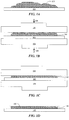
- FIGS. 1A-1D are cross-sectional schematic illustrations of an exemplary method of electrode fabrication.
- the method comprises applying pressure, during the electrode fabrication process, to a composition comprising a particulate electronically conductive material and an electrode active material.
- composition 102 can be provided.
- Composition 102 can comprise an electrode active material and a particulate electronically conductive material.
- Composition 102 can also comprise a binder, such as a polymeric binder.
- the composition used to form the electrode can be formed on a substrate (e.g., cast or otherwise deposited onto a current collector) prior to applying the relatively large compressive force to the composition to form the electrode.
- a substrate e.g., cast or otherwise deposited onto a current collector
- composition 102 in FIG. 1A can first be formed over substrate 103 (which can be a current collector) prior to a compressive force being applied to the composition (as illustrated in FIGS. 1B-1C , and described in more detail below) to form the electrode.
- substrate 103 which can be a current collector
- the electrode composition can be deposited directly on the device used to apply the compressive force to the composition.
- the electrode active material within the composition can be in particulate form or in any other form suitable for forming electrodes via the application of pressure.
- a variety of types of electrode active material suitable for use are described in more detail below.
- the electrode active material can be a sulfur containing material, such as elemental sulfur.
- Composition 102 can also comprise a particulate electronically conductive material.
- the particulate electronically conductive material can be used to impart electronic conductivity to the composition.
- the other components of the composition may not be sufficiently electronically conductive to provide a pathway for electrons to exit during discharge of the electrochemical cell using the electrode.
- the resulting electrode can be sufficiently electronically conductive to provide a pathway for electrons to enter and/or leave the electrode.
- a variety of types of particulate electronically conductive materials can be used in association with the systems and methods described herein, as described in more detail below.
- the particulate electronically conductive material can comprise carbon, such as carbon black.
- the carbon may be relatively hard and/or capable of withstanding relatively high applied pressures, as described in more detail below.
- Porocarb® porous carbons manufactured by Heraeus Quarzglas GmbH & Co., Kleinostheim, Germany
- the particulate electronically conductive material is porous, as described in more detail elsewhere herein.
- the conductive additive can include graphitic carbon (e.g., graphite and/or graphene), which can, according to certain embodiments, help maintain smoothness of the electrode when pressure is applied.
- Composition 102 can also include other components.
- the composition comprises at least one binder.
- the binder can be, for example, a polymeric binder, such as polyvinyl alcohol.
- Other suitable binders for use in electrode precursor composition are described in more detail elsewhere herein.
- pressure is applied to the electrode precursor composition.
- Pressure can be applied to the electrode precursor composition to form the electrode using any suitable method. Referring back to FIG. 1B , composition 102 has been placed within a press including press plates 104. Pressure can be applied to composition 102 by moving plates 104 in the direction of arrows 106. This can result in the application of compressive force to composition 102. As illustrated in FIG. 1C , applying the compressive force to composition 102 can flatten composition 102 to produce relatively flat and smooth electrode 108.
- the magnitude of the pressure applied to the composition during fabrication of the electrode can be relatively large. Applying relatively large pressures to the electrode precursor compositions described herein can result in the formation of a relatively smooth electrode. As described elsewhere, the use of relatively smooth electrodes can be advantageous, for example, in electrochemical cells in which an isotropic force is applied during charge and/or discharge.
- the invention comprises applying a pressure of at least about 590 Newtons/cm 2 , at least about 750 Newtons/cm 2 , at least about 1000 Newtons/cm 2 , or at least about 1765 Newtons/cm 2 to the composition to form the electrode.
- Some embodiments comprise applying a pressure of at least about 590 Newtons/cm 2 and up to about 6000 Newtons/cm 2 , or at least about 1765 Newtons/cm 2 and up to about 6000 Newtons/cm 2 to the composition to form the electrode.
- a liquid wetting agent can be employed during the step of applying the pressure to the electrode precursor composition to form the electrode.
- composition 102 can include a liquid wetting agent.
- the use of liquid wetting agents can be particularly useful in producing smooth electrodes when large pressures are applied to electrode precursor compositions, such as composition 102 in FIG. 1A .
- liquid wetting agent aides in the settling of the particulate material within the electrode precursor composition to produce a relatively smooth external surface.
- the presence of the liquid wetting agent leads to plasticization of the binder, which can allow for reflow of the cathode matrix. It was expected that the use of such liquid wetting agents would lead to cracking any other discontinuities within the finally formed electrode. However, it was discovered that such liquid wetting agents could be used, particularly under high applied pressures, while the formation of cracks and other discontinuities in the electrode was limited and/or avoided.
- the liquid wetting agent comprises an aqueous and/or non-aqueous fluid.
- suitable types of liquid wetting agents include, but are not limited to, water, alcohols (e.g., isopropyl alcohol, methanol, ethanol, propanol, and/or butanol), tetrahydrofuran, dimethoxyethane, acetone, toluene, xylene, acetonitrile, cyclohexane and the like.
- the liquid wetting agent comprises a mixture of water and isopropyl alcohol.
- the ratio of water to isopropyl alcohol is from 1:4 to about 4:1, from about 1:2 to about 2:1, from about 1:1.5 to about 1.5:1, or from about 1:1.1 to about 1:1.1.
- wetting agents and their relative amounts. In some cases, it may be desirable to select one or more wetting agents that are capable of plasticizing the binder used in the electrode fabrication process to a sufficient degree to allow the electrode components to flow.
- the liquid wetting agent can make up a relatively high weight percentage of the electrode precursor composition when the pressure is applied to the electrode precursor composition.
- the liquid wetting agent makes up at least about 1 wt%, at least about 5 wt%, at least about 10 wt%, at least about 20 wt%, at least about 40 wt% (and/or, in certain embodiments, up to about 60 wt%, or more) of the electrode precursor composition to which pressure is applied, at a point just before the pressure is applied to the electrode precursor composition.
- the wetting agent can make up at least about 1 wt%, at least about 5 wt%, at least about 10 wt% (and/or, in certain embodiments, up to about 40 wt%, or more) of the resulting composition.
- the process of forming the electrode comprises at least partially removing the liquid wetting agent from the electrode precursor composition.
- the liquid wetting agent can be at least partially removed to leave behind a relatively dry electrode. Removing at least a portion of the liquid wetting agent can be achieved, for example, by drying the compressed electrode precursor, optionally in a heated environment (e.g., within an oven).
- removing at least a portion of the liquid wetting agent from the electrode precursor composition comprises removing at least about 50 wt%, at least about 75 wt%, at least about 90 wt%, at least about 95 wt%, or at least about 99 wt% of the liquid wetting agent from the electrode precursor composition.
- the electrodes described herein (and/or the porous support structures within the electrode described herein) can maintain a relatively high degree of porosity, even after relatively large pressures have been applied to the electrode precursor compositions from which the electrodes are formed. It has unexpectedly been discovered that the application of such relatively large forces can be used to form electrodes without damaging the material from which the electrode is formed. It was expected that the application of large forces to electrode precursor compositions would fracture or otherwise mechanically deform the material within the electrode precursor composition, such as the particulate electronically conductive material. By using certain types of particulate electronically conductive materials, one can avoid the mechanical breakdown of such materials, which can allow for the application of large pressures.
- particulate electronically conductive materials having relatively large amounts of internal porosity (i.e., intraparticle porosity) and external shapes that lead to a relatively small amount of porosity between the particles (i.e., interparticle porosity) when the particles are agglomerated. It is believed that the use of such particles can allow the final electrode to maintain its overall porosity even when large pressures are applied (which, in other systems, could lead to the shifting of the particles, reducing the interparticle porosity and thus, the overall porosity). In certain embodiments, the use of porous particles having pore sizes larger than 0.1 micrometers is believed to impart further structural stability to the resulting electrode, allowing for the application of relatively large pressures during the fabrication process.
- porous particulate electronically conductive material that is relatively hard and stable under pressure can allow one to maintain the final porosity of the electrode after relatively large pressures have been applied during the electrode fabrication process.
- Such pressure-resistant porous particulate electronically conductive materials may be formed, according to certain embodiments, using a templating process in which a sacrificial material is combined with a second material, after which the sacrificial material is removed from the combination. In some cases, the structure of the second material can be substantially maintained after the sacrificial material has been removed from the combination.
- the porous particulate electronically conductive material can be made by assembling a plurality of templating elements made of a sacrificial material into a template.
- a second material can be mixed with the templating elements.
- the second material comprises, in some embodiments, a material from which the porous particulate electronically conductive material is to be made (e.g., a carbon-based material).
- the second material comprises a precursor of the porous particulate electronically conductive material, which might be converted to form the porous particulate electronically conductive material via, for example, a reaction (e.g., pyrolysis of a hydrocarbonaceous material).
- the templating elements can, in certain embodiments, be arranged such that they form an interconnected network, and the second material can be transported into the interstices of the network. After the templating elements have been arranged within the second material, they can be removed from the mixture to leave behind pores within a porous particulate electronically conductive material.
- Porocarb® porous carbons manufactured by Heraeus Quarzglas GmbH & Co., Kleinostheim, Germany
- Porocarb® HD3 are exemplary porous particulate electronically conductive materials made using such a process.
- the ability to maintain porosity of an electrode (and/or of a porous support structure used to make an electrode) after the application of relatively large forces during the electrode fabrication process can allow one, according to certain embodiments, to form electrodes that are both relatively smooth and highly porous.
- smooth electrodes can be useful in enhancing electrochemical cell performance when an isotropic force is applied during charge and/or discharge of the electrochemical cell.
- highly porous electrodes can be desirable in certain instances as they can provide for a relatively high degree of interaction between the electrode active material and the electrolyte, which can be important for effective cell performance.
- a "pore” refers to a conduit, void, or passageway, at least a portion of which is surrounded by the medium in which the pore is formed.
- voids within a material that are completely surrounded by the material are not considered pores within the context of the invention.
- pores include both the interparticle pores (i.e., those pores defined between particles when they are packed together, e.g., interstices) and intraparticle pores (i.e., those pores lying within the external geometric surfaces of the individual particles).
- Pores may comprise any suitable cross-sectional shape including irregular shapes and regular shapes (e.g., substantially circular shapes, substantially elliptical shapes, substantially polygonal shapes, and the like).
- the electrode after the pressure has been applied to the composition, the electrode has a porosity of at least about 40%. In certain embodiments, after the pressure has been applied to the composition, the electrode has a porosity of at least about 50% or at least about 60% (and/or, in some embodiments, up to about 70%, or more). In some embodiments, after the pressure has been applied to the composition, the electrode has a porosity of at least about 40% and up to about 70%. The porosity of an electrode, when expressed as a percentage, corresponds to the percentage of the electrode's geometric volume that is occupied by void volume.
- the void volume within an electrode refers to the porous portion of an electrode that is not occupied by electrode active material (e.g., sulfur), conductive material (e.g., carbon, metal, etc.), binder, or other materials that provide structural support, as measured when the electrode active material is present within the electrode (i.e., after compression of the electrode) and the electrode is fully charged.
- electrode active material e.g., sulfur
- conductive material e.g., carbon, metal, etc.
- binder e.g., binder, or other materials that provide structural support, as measured when the electrode active material is present within the electrode (i.e., after compression of the electrode) and the electrode is fully charged.
- the void volume of an electrode generally includes the volume of the pores in the particles from which the electrode is formed, as well as interstices between the particles. Void volume may be occupied by electrolyte (when the electrode is in use), gases, and/or other non-electrode materials.
- One of ordinary skill in the art would be capable of determining the void volume within an electrode by performing, for example, mercury intrusion porosimetry according to ASTM Standard Test D4284-07.
- the final percentage porosity can then be calculated by dividing the void volume of the electrode by the geometric volume of the electrode (e.g., calculated by measuring the size of the electrode using macroscopic measurement techniques).
- the porosity of a porous support structure within the electrode is relatively large.
- the porous support structure within the electrode has a porosity of at least about 40%, at least about 50%, at least about 60%, or at least about 70% (and/or, in some embodiments, up to about 80%, or more).
- the "porous support structure" of an electrode refers to the portions of the electrode that are not occupied by gases (e.g., air), liquid, and electrode active material.
- gases e.g., air
- the porosity of a porous support structure can be determined by removing the electrode active material from the electrode, and performing mercury intrusion porosimetry according to ASTM Standard Test D4284-07.
- the final percentage porosity of the porous support structure can then be calculated by dividing the geometric volume of the porous support structure (e.g., calculated by measuring the size of the porous support structure using macroscopic measurement techniques) by the void volume of the porous support structure.
- the systems and methods described herein can be used to produce electrodes with relatively smooth external geometric surfaces.
- the "external geometric surface" of an object refers to the surface defining the outer boundaries of the object when analyzed at substantially the same scale as the maximum cross-sectional dimension of the object.
- the external geometric surface of an object does not include the internal surfaces, such as the surfaces defined by pores within a porous object.
- electrode 108 comprises external geometric surface 110. The surfaces of the pores within electrode 108, on the other hand, do not constitute external geometric surfaces of electrode 108.
- an external geometric surface of the electrode has a root mean square (RMS) surface roughness of less than about 15 micrometers, less than about 10 micrometers, less than about 5 micrometers, less than about 1 micrometer, or less than about 0.5 micrometers over a geometric surface area of at least about 10,000 square micrometers (and/or in some embodiments, over a geometric surface area of at least about 100,000 square micrometers, at least about 1,000,000 square micrometers, at least about 10,000,000 square micrometers, at least about 1 square centimeter, and/or up to about 10 square centimeters, up to about 100 square centimeters, or more).
- RMS root mean square
- an external geometric surface of the electrode has a root mean square surface roughness of from about 0.1 micrometers to about 15 micrometers, from about 0.1 micrometers to about 10 micrometers, from about 0.1 micrometers to about 5 micrometers, from about 0.1 micrometers to about 1 micrometer, or from about 0.1 micrometers to about 0.5 micrometers over a geometric surface area of at least about 10,000 square micrometers (and/or in some embodiments, over a geometric surface area of at least about 100,000 square micrometers, at least about 1,000,000 square micrometers, at least about 10,000,000 square micrometers, at least about 1 square centimeter, and/or up to about 10 square centimeters, up to about 100 square centimeters, or more).
- an external geometric surface of the electrode has a root mean square surface roughness of from about 0.1 micrometers to about 15 micrometers, from about 0.1 micrometers to about 10 micrometers, from about 0.1 micrometers to about 5 micrometers, from about 0.1 micrometers to about 1 micrometer, or from about 0.1 micrometers to about 0.5 micrometers when sampled over a geometric surface area of about 250,000 square micrometers.
- RMS surface roughness which is a descriptor for the standard deviation of the distribution of surface heights. The RMS surface roughness is calculated as the average between the height deviations and the mean line/surface, taken over the evaluation area.
- the RMS surface roughness mean line is the line that divides the profile so that the sum of the squares of the deviations of the profile height from it is equal to zero.
- the surface height is measured at 1.227 points per square micrometer, such measurements distributed spatially evenly across the measured surface area.
- the RMS surface roughness of a given electrode is determined by examining the electrode an 11x magnification.
- Example 1 describes an exemplary experimental determination of the RMS surface roughness of the external geometric surface of an electrode, according to one embodiment.
- the resulting electrode can be relatively thin.
- the resulting electrode after pressure has been applied to the electrode composition, the resulting electrode can be in the form of a thin film.
- the thickness of the electrode is less than or equal to about 1 mm, less than or equal to about 100 micrometers, or less than or equal to about 50 micrometers.
- the thickness of the electrode is at least about 10 micrometers and less than or equal to about 1 mm, at least about 10 micrometers and less than or equal to about 100 micrometers, or at least about 10 micrometers and less than or equal to about 50 micrometers.
- inventive electrodes are also described. Certain of the inventive electrodes are obtainable using any of the methods described elsewhere herein. An example of one such inventive electrode is illustrated, for example, in FIG. 1D .
- inventive electrodes can include any of the materials described elsewhere herein.
- the electrode can comprise, for example, a particulate electronically conductive material (which may be porous) and an electrode active material (such as, for example, sulfur).
- the electrode can comprise, in certain embodiments, a binder, such as a polymeric binder.
- the inventive electrodes can also have any of the electrode properties described elsewhere herein, including porosity, smoothness, pore size distribution, and/or any of the other properties described elsewhere herein.
- the particulate electronically conductive material can be a carbon-based material, such as carbon black.
- Other exemplary particulate electronically conductive materials that can be used to form all or part of the particles within the porous support structures described herein include, but are not limited to, metals (e.g., nickel, copper, magnesium, aluminum, titanium, scandium, iron, alloys and/or other combinations of these), conductive polymers (poly(3,4-ethylenedioxythiphene) (PEDOT), poly(methylenedioxythiophene) (PMDOT), other thiophenes, polyaniline (PANI), polypyrrole (PPy)), and the like.
- metals e.g., nickel, copper, magnesium, aluminum, titanium, scandium, iron, alloys and/or other combinations of these
- conductive polymers poly(3,4-ethylenedioxythiphene) (PEDOT), poly(methylenedioxythiophene) (PMDOT), other thiophenes, polyaniline (PANI), polypyrrole (
- the particulate electronically conductive material comprises Porocarb® porous carbons (manufactured by Heraeus Quarzglas GmbH & Co., Kleinostheim, Germany), such as Porocarb® HD3.
- the particulate electronically conductive material has a bulk electronic resistivity of less than about 10 -3 ohm-m, less than about 10 -4 ohm-m, less than about 10 -5 ohm-m, or less than about 10 -7 ohm-m at 20 °C.
- At least about 50 wt%, at least about 75 wt%, at least about 90 wt%, at least about 95 wt%, or at least about 99 wt% of the particulate electronically conductive material has a bulk electrical resistivity of less than about 10 -3 ohm-m, less than about 10 -4 ohm-m, less than about 10 -5 ohm-m, or less than about 10 -7 ohm-m at 20 °C.
- the effective bulk resistivity of the electrode after the material has been compressed and dried is from about 10 -3 ohm-m to about 10 ohm-m.
- the effective bulk resistivity of an electrode can be determined by measuring the resistance across the electrode (which has known dimensions). Using this resistance measurement, the effective electronic conductivity of the electrode can then be back calculated using the geometry across which the resistance was measured.
- the particulate electronically conductive material may have any suitable particle size distribution.
- the particulate electronically conductive material used to form the electrodes described herein can have maximum cross-sectional dimensions within a designated range. For example, in some cases, at least about 50%, at least about 75%, at least about 90%, at least about 95%, or at least about 99%, or substantially all of the total volume of the particulate electronically conductive material within an electrode can be made up of particles having maximum cross-sectional dimensions of between about 0.1 micrometers and about 45 micrometers, between about 0.1 micrometers and about 10 micrometers, between about 1 micrometer and about 10 micrometers, or between about 1 micrometer and about 3 micrometers.
- the particles used to form a porous support structure can have an average maximum cross-sectional dimension of between about 0.1 micrometers and about 45 micrometers, between about 0.1 micrometers and about 10 micrometers, between about 1 micrometer and about 10 micrometers, or between about 1 micrometer and about 3 micrometers.
- the "maximum cross-sectional dimension" of an article refers to the largest distance between two opposed boundaries of the article that may be measured.
- One of ordinary skill in the art would be capable of measuring the maximum cross-sectional dimension distributions of a particulate electronically conductive material by examining scanning electron microscope (SEM) images of the particulate material.
- the "maximum external surface cross-sectional dimension" of a pore or other indentation in a particle is the largest dimension between two points of the pore or other feature measured along the geometric surface of the particle. For example, for a 10-micrometer diameter cylindrical pore that extends through the center of a 1 millimeter spherical particle (resulting in a pore with a length of 1 millimeter), the maximum surface cross-sectional dimension of the pore would be 10 micrometers.
- the distribution of the cross-sectional diameters of the pores within a given porous support structure and/or within the assembled electrode can be chosen to enhance the performance of the electrochemical cell.
- the "cross-sectional diameter" of a pore refers to a cross-sectional diameter as measured using ASTM Standard Test D4284-07.
- the "average cross-sectional diameter" of a plurality of pores refers to the number average of the cross-sectional diameters of each of the plurality of the pores.
- One of ordinary skill in the art would be capable of calculating the distribution of cross-sectional diameters and the average cross-sectional diameter of the pores within a porous structure (e.g., a small-scale porous support structure, a large scale porous support structure, and electrode assembled from a combination of porous support structures) using mercury intrusion porosimetry as described in ASTM Standard Test D4284-07.
- a porous structure e.g., a small-scale porous support structure, a large scale porous support structure, and electrode assembled from a combination of porous support structures
- ASTM Standard Test D4284-07 can be used to produce a distribution of pore sizes plotted as the cumulative intruded pore volume as a function of pore diameter.
- porosimetry measurements may be supplemented using Brunauer-Emmett-Teller (BET) surface analysis, as described, for example, in S. Brunauer, P. H. Emmett, and E. Teller, J. Am. Chem. Soc., 1938, 60, 309 .
- BET Brunauer-Emmett-Teller
- a porous support structure and/or an assembled electrode can be configured to comprise pores with cross-sectional diameters that are larger than sub-nanometer scale and single nanometer scale pores, which can be relatively easily clogged with electrochemical cell reaction by-product and/or can be too small to allow for the passage of electrolyte (e.g., liquid electrolyte) into the pores of the electrode due to, for example, capillary forces.
- electrolyte e.g., liquid electrolyte
- the pores within a porous support structure and/or within an assembled electrode may have cross-sectional diameters that are smaller than millimeter-scale pores, which may be so large that they render the electrode mechanically unstable.
- the total pore volume of a porous structure is described.
- the porous support structure can be said to comprise a plurality of pores, wherein each pore of the plurality of pores has a pore volume, and the plurality of pores has a total pore volume defined by the sum of each of the individual pore volumes.
- at least about 50%, at least about 75%, at least about 90%, at least about 99%, or substantially all of the total pore volume within the assembled electrode is defined by pores having cross-sectional diameters of between about 0.1 micrometers and about 10 micrometers, or between about 1 micrometer and about 3 micrometers.
- the average cross-sectional diameter of the pores within the assembled electrode is between about 0.1 micrometers and about 10 micrometers, or between about 1 micrometer and about 3 micrometers.
- the porosity (e.g., distribution of pores, distribution of pore sizes, void volume, etc.) of an assembled electrode is determined in the absence of electrode active material within the pores of the electrode. This can be achieved, for example, by removing the electrode active material from the pores of the electrode and subsequently performing mercury intrusion porosimetry and/or by performing porosimetry before electrode active material has been added to the electrode.
- the assembled electrode may comprise pores with relatively uniform cross-sectional diameters. Not wishing to be bound by any theory, such uniformity may be useful in maintaining relatively consistent structural stability throughout the bulk of the porous electrode.
- the ability to control the pore size to within a relatively narrow range can allow one to incorporate a large number of pores that are large enough to allow for fluid penetration (e.g., electrolyte penetration) while maintaining sufficiently small pores to preserve structural stability.
- the distribution of the cross-sectional diameters of the pores within an assembled electrode can have a standard deviation of less than about 50%, less than about 25%, less than about 10%, less than about 5%, less than about 2%, or less than about 1% of the average cross-sectional diameter of the plurality of pores.
- the percentage comparisons between the standard deviation and the average cross-sectional diameters of the pores outlined above can be obtained by dividing the standard deviation by the average and multiplying by 100%.
- an electrode active material can be substantially contained within pores of the porous support structures described herein.
- the electrode active material can be added to form electrodes using the porous support structure.
- a first material that is said to be "substantially contained" within the pores of a second material is one that at least partially lies within the imaginary volumes defined by the outer boundaries of the pores of the second material.
- a material substantially contained within a pore can be fully contained within the pore, or may only have a fraction of its volume contained within the pore, but a substantial portion of the material, overall, is contained within the pore.
- a first material e.g., an electrode active material
- a second material e.g., a porous support structure
- FIG. 2 includes a schematic illustration of an electrochemical cell 210 comprising a cathode 212 and an anode 216.
- the electrochemical cell comprises electrolyte 214 (which can include a separator).
- the electrolyte can include one or more components in electrochemical communication with the cathode and the anode. While the anode, cathode, and electrolyte in FIG. 2 are shown as having a planar configuration, other embodiments may include non-planar configurations (e.g., cylindrical, serpentine, etc.).
- electrochemical cell 210 also includes a housing structure 217.
- the electrochemical cell can comprise an electrode that is obtained using any of the methods described elsewhere herein.
- cathode 212 can be made using any of the electrode fabrication techniques described herein.
- Cathode 212 can be made, for example, by applying a pressure of at least about 590 Newtons/cm 2 to a composition comprising a particulate electronically conductive material, an electrode active material, a binder and a liquid wetting agent.
- Cathode 212 can also have any of the electrode properties described elsewhere herein.
- cathode 212 has a porosity of at least about 40%.
- cathode 212 has an external geometric surface with a root mean square surface roughness of less than about 15 micrometers over a geometric surface area of at least about 1 cm 2 (and/or in some embodiments, over a geometric surface area of at least about 10 cm 2 and/or up to about 100 cm 2 , or more).
- the electrochemical cell comprises a second electrode comprising lithium (e.g., lithium metal and/or a lithium alloy).
- a second electrode comprising lithium (e.g., lithium metal and/or a lithium alloy).
- anode 216 can comprise a lithium-based electrode active material, according to certain embodiments.
- orientation of the components can be varied, and it should be understood that there are other embodiments in which the orientation of the layers is varied. Additionally, non-planar arrangements, arrangements with proportions of materials different than those shown, and other alternative arrangements are useful in connection with the present invention.
- a typical electrochemical cell also would include, of course, current collectors, external circuitry, and the like. Those of ordinary skill in the art are well aware of the many arrangements that can be utilized with the general schematic arrangement as shown in the figures and described herein.
- Electrodes comprising the particulate electronically conductive materials and electrode active materials described herein (including, for example, the relatively smooth electrodes described herein) can be used as anodes and/or cathodes.
- cathode 212 of electrochemical cell 210 can be relatively smooth and/or have any of the other electrode properties described herein.
- anode 216 comprises lithium (e.g., lithium metal and/or a lithium alloy) as an active species.
- anode 216 can comprise a lithium metal foil, in certain embodiments.
- the electrochemical cells and/or the electrodes described herein can be configured to withstand an applied anisotropic force (e.g., a force applied to enhance the morphology of an electrode within the cell) while maintaining their structural integrity (including void volume, in certain embodiments).
- an applied anisotropic force e.g., a force applied to enhance the morphology of an electrode within the cell
- any of the electrodes described herein can be part of an electrochemical cell that is constructed and arranged such that, during at least one period of time during charge and/or discharge of the cell, an anisotropic force with a component normal to the active surface of an electrode within the electrochemical cell (e.g., an anode comprising lithium metal and/or a lithium alloy) is applied to the cell.
- the applied anisotropic force can be selected to enhance the morphology of an electrode (e.g., an anode such as a lithium metal and/or a lithium alloy anode), and the cathode can comprise a particulate electronically conductive material and an electrode active material.
- the cathode can be relatively smooth, for example, having a surface roughness within any of the ranges described elsewhere herein.
- anisotropic force is given its ordinary meaning in the art and means a force that is not equal in all directions.
- a force equal in all directions is, for example, internal pressure of a fluid or material within the fluid or material, such as internal gas pressure of an object.
- forces not equal in all directions include forces directed in a particular direction, such as the force on a table applied by an object on the table via gravity.
- Another example of an anisotropic force includes a force applied by a band arranged around a perimeter of an object.
- a rubber band or turnbuckle can apply forces around a perimeter of an object around which it is wrapped.
- the band may not apply any direct force on any part of the exterior surface of the object not in contact with the band.
- the band when the band is expanded along a first axis to a greater extent than a second axis, the band can apply a larger force in the direction parallel to the first axis than the force applied parallel to the second axis.
- the anisotropic force comprises a component normal to an active surface of an electrode within an electrochemical cell.
- active surface is used to describe a surface of an electrode that is in physical contact with the electrolyte and at which electrochemical reactions may take place.
- cathode 212 can include cathode active surface 218 and/or anode 216 can include anode active surface 220.
- an active surface of an electrode refers to an external geometric surface of the electrode.
- a force with a "component normal" to a surface is given its ordinary meaning as would be understood by those of ordinary skill in the art and includes, for example, a force which at least in part exerts itself in a direction substantially perpendicular to the surface.
- a force which at least in part exerts itself in a direction substantially perpendicular to the surface For example, in the case of a horizontal table with an object resting on the table and affected only by gravity, the object exerts a force essentially completely normal to the surface of the table. If the object is also urged laterally across the horizontal table surface, then it exerts a force on the table which, while not completely perpendicular to the horizontal surface, includes a component normal to the table surface.
- FIG. 2 An applied force with a component normal to an active surface of an electrode is illustrated in FIG. 2 .
- an anisotropic force may be applied in the direction of arrow 250.
- Arrow 251 illustrates the component of force 250 that is normal to active surface 220 of anode 216 (and also, in this case, normal to active surface 218 of cathode 212).
- the component of the anisotropic force that is normal to an active surface of an electrode may correspond to the component normal to a plane that is tangent to the curved surface at the point at which the anisotropic force is applied.
- the anisotropic force may be applied, in some cases, at one or more pre-determined locations, optionally distributed over the active surface of the anode. In some embodiments, the anisotropic force is applied uniformly over the active surface of the anode.
- any of the electrode properties e.g., low surface roughness, porosity, pore size distribution, etc.
- performance metrics described herein may be achieved, alone or in combination with each other, while an anisotropic force is applied to the electrochemical cell (e.g., during charge and/or discharge of the cell) during charge and/or discharge.
- the anisotropic force applied to porous support structure, to the electrode, and/or to the electrochemical cell containing the electrode can include a component normal to an active surface of an electrode (e.g., an anode such as a lithium metal and/or lithium alloy anode within the electrochemical cell and/or the porous electrode comprising multiple porous support structures).
- a component normal to an active surface of an electrode e.g., an anode such as a lithium metal and/or lithium alloy anode within the electrochemical cell and/or the porous electrode comprising multiple porous support structures.
- the component of the anisotropic force that is normal to the active surface of the electrode defines a pressure of at least about 20, at least about 25, at least about 35, at least about 40, at least about 50, at least about 75, at least about 90, at least about 100, at least about 125 or at least about 150 Newtons per square centimeter, while the desired electrode properties are present.
- the component of the anisotropic force normal to the active surface may, for example, define a pressure of less than about 200, less than about 190, less than about 175, less than about 150, less than about 125, less than about 115, or less than about 110 Newtons per square centimeter, while the desired electrode properties are present.
- forces and pressures are generally described herein in units of Newtons and Newtons per unit area, respectively, forces and pressures can also be expressed in units of kilograms-force and kilograms-force per unit area, respectively.
- forces and pressures can also be expressed in units of kilograms-force and kilograms-force per unit area, respectively.
- kilogram-force-based units One of ordinary skill in the art will be familiar with kilogram-force-based units, and will understand that 1 kilogram-force is equivalent to about 9.8 Newtons.
- the anisotropic forces applied during charge and/or discharge as described herein may be applied using any method known in the art.
- the force may be applied using compression springs.
- Forces may be applied using other elements (either inside or outside a containment structure) including, but not limited to Belleville washers, machine screws, pneumatic devices, and/or weights, among others.
- cells may be pre-compressed before they are inserted into containment structures, and, upon being inserted to the containment structure, they may expand to produce a net force on the cell. Suitable methods for applying such forces are described in detail, for example, in U.S. Patent Application No. 12/535,328, filed August 4, 2009 , entitled "Application of Force in Electrochemical Cells" to Scordilis-Kelley et al.
- the electrode active material within the pores can comprise sulfur.
- the electrode active material within the pores can comprise electroactive sulfur-containing materials.
- Electroactive sulfur-containing materials refers to electrode active materials which comprise the element sulfur in any form, wherein the electrochemical activity involves the oxidation or reduction of sulfur atoms or moieties.
- the electroactive sulfur-containing material may comprise elemental sulfur (e.g., S 8 ).
- the electroactive sulfur-containing material comprises a mixture of elemental sulfur and a sulfur-containing polymer.
- suitable electroactive sulfur-containing materials may include, but are not limited to, elemental sulfur, sulfides or polysulfides (e.g., of alkali metals) which may be organic or inorganic, and organic materials comprising sulfur atoms and carbon atoms, which may or may not be polymeric.
- Suitable organic materials include, but are not limited to, those further comprising heteroatoms, conductive polymer segments, composites, and conductive polymers.
- an electroactive sulfur-containing material within an electrode e.g., a cathode
- the electroactive sulfur-containing material comprises at least about 50 wt%, at least about 75 wt%, or at least about 90 wt% sulfur.
- sulfur-containing polymers examples include those described in: U.S. Patent Nos. 5,601,947 and 5,690,702 to Skotheim et al. ; U.S. Patent Nos. 5,529,860 and 6,117,590 to Skotheim et al. ; U.S. Patent No. 6,201,100 issued Mar. 13, 2001, to Gorkovenko et al. , and PCT Publication No. WO 99/33130 .
- Other suitable electroactive sulfur-containing materials comprising polysulfide linkages are described in U.S. Patent No. 5,441,831 to Skotheim et al. ; U.S. Patent No. 4,664,991 to Perichaud et al. , and in U.S.
- Still further examples of electroactive sulfur-containing materials include those comprising disulfide groups as described, for example in, U.S. Patent No. 4,739,018 to Armand et al. ; U.S. Patent Nos. 4,833,048 and 4,917,974, both to De Jonghe et al. ; U.S. Patent Nos. 5,162,175 and 5,516,598, both to Visco et al. ; and U.S. Patent No. 5,324,599 to Oyama et al.
- the cathode active species comprises a hydrogen-absorbing alloy, such as those commonly used in nickel metal hydride batteries.
- a hydrogen-absorbing alloy such as those commonly used in nickel metal hydride batteries.
- the electrode (including, in some embodiments, the electrode precursor composition) comprises a binder.
- binder generally refers to material that is not an electrode active material and is not included to provide an electrically conductive pathway for the electrode.
- an electrode might contain binder to facilitate internal cohesion within the cathode. Polymeric or non-polymeric binder materials can be used.
- binder materials include, but are not limited to, polyvinylidene fluoride (PVDF)-based polymers, such as poly(vinylidene fluoride) (PVDF) and its co- and terpolymers with hexafluoroethylene, tetrafluoroethylene, chlorotrifluoroethylene, poly(vinyl fluoride), polytetraethylene (PTFE), ethylene-tetrafluoroethylene copolymers (ETFE), polybutadiene, cyanoethyl cellulose, carboxymethyl cellulose and its blends with styrene-butadiene rubber, polyacrylonitrile, ethylene propylene diene terpolymers, styrene-butadiene rubbers (SBR), polyimides or ethylene-vinyl acetate copolymers.
- PVDF polyvinylidene fluoride
- PVDF poly(vinylidene fluoride)
- PTFE polytetraethylene
- the binder material may be substantially soluble in aqueous fluid carriers and may include, but is not limited to, cellulose derivatives, typically methylcellulose (MC), carboxy methylcellulose (CMC) and hydroxypropyl methylcellulose (HPMC), polyvinyl alcohol (PVA), polyacrylic acid salts, polyacryl amide (PA), polyvinyl pyrrolidone (PVP) or polyethylene oxide (PEO).
- the binder material is poly(ethylene-co-propylene-co-5-methylene-2-norbornene) (EPMN), which may be chemically neutral (e.g,. inert) towards cell components, including polysulfides.
- the amount of binder within the electrode may be, in some embodiments, relatively small.
- binder makes up less than about 20 wt%, less than about 10 wt%, less than about 5 wt%, less than about 2 wt%, or less than about 1 wt of the mass of solids within the electrode.
- less than about 20 wt%, less than about 10 wt%, less than about 5 wt%, less than about 2 wt%, or less than about 1 wt% of the mass of solids within the electrode is made of up polymeric material.
- the particulate electronically conductive material and the electrode active material make up a relatively large amount of the solids within the electrode.
- the particulate electronically conductive material and the electrode active material together, make up at least about 60 wt%, at least about 70 wt%, at least about 80 wt%, at least about 90 wt%, or at least about 95 wt% of the mass of solids in the electrode.
- the inventive electrodes described herein can be paired with a counter electrode in an electrochemical cell.
- the counter electrode can comprise lithium as an anode active material.
- Suitable electrode active materials comprising lithium include, but are not limited to, lithium metal (e.g., lithium foils, lithium deposited onto a conductive substrate, and the like) and lithium alloys (e.g., lithium-aluminum alloys, lithium-tin alloys, lithium-silicon alloys, and the like).
- an electroactive lithium-containing material of an electrode active layer of a counter electrode comprises greater than 50 wt% lithium, greater than 75 wt% lithium, or greater than 90 wt% lithium.
- electrode active materials that can be used in the counter electrode include, but are not limited to, alkali metals (e.g., sodium, potassium, rubidium, caesium, francium), alkaline earth metals (e.g., beryllium, magnesium, calcium, strontium, barium, radium), and the like.
- alkali metals e.g., sodium, potassium, rubidium, caesium, francium
- alkaline earth metals e.g., beryllium, magnesium, calcium, strontium, barium, radium
- the electrodes and support structure configurations described herein can be used in electrochemical cells for a wide variety of devices, such as, for example, electric vehicles, load-leveling devices (e.g., for solar- or wind-based energy platforms), portable electronic devices, and the like.
- electrochemical cell includes primary and secondary electrochemical cells. Accordingly, the inventive electrochemical cell arrangements and materials described herein can be used in primary cells and/or in secondary cells (including primary batteries and secondary batteries), which can be charged and discharged numerous times. In some embodiments, the materials, systems, and methods described herein can be used in association with lithium-based electrochemical cells, and batteries thereof.
- the electrodes comprising the porous support structures described herein can be used in electrochemical cells comprising another electrode comprising lithium, such as lithium metal and/or a lithium alloy.
- the materials, systems, and methods described herein can be used in association with lithium-sulfur electrochemical cells and/or batteries thereof.
- This example describes the fabrication of smooth cathodes comprising sulfur-based electrode active materials and particulate electronically conductive material in the form of carbon additives. Smooth cathodes were fabricated by applying relatively large pressures to an electrode precursor composition. The electrode precursor composition was wetted prior to applying pressure.
- the cathode precursor composition was formed by mixing Porocarb® HD3 porous carbon (Heraeus Quarzglas GmbH & Co., Kleinostheim, Germany), elemental sulfur (Sigma Aldrich, St. Louis, MO; mesh size of 100, and purity of 99.8%), a polyvinyl alcohol (PVOH) binder, and a solvent solution comprising isopropanol, deionized water and 1-methoxy-2-propanol.
- the final solids composition of the slurry was 55 wt% sulfur, 40 wt% carbon, and 5 wt % PVOH binder. The solids were added to the slurry until the solvent made up 70-85 wt % of the slurry.
- the slurry was applied to an aluminum foil via a slot die method. The applied slurry was then dried to remove all solvent.
- the steel blocks were then placed in a carver press and compressed - in four separate compression steps - at a pressure of 882.6 Newtons/cm 2 (90 kg f /cm 2 ). Between each compression step, the cathode was removed and rotated 90 degrees while the orientation of the steel blocks was maintained.
- the root mean square (RMS) surface roughness ( R q ) values of the cathodes were between 9.6 micrometers and 18.0 micrometers. After applying compressive pressure, however, the cathodes were much smoother, with external surfaces exhibiting RMS surface roughness values of 0.2 micrometers to 1.6 micrometers.
- RMS surface roughness measurements the surface height was sampled over an area of 250,000 square micrometres at 11x magnification, with a sampling point density of 1.227 points per square micrometer, evenly distributed across the sampled area.
- the cathodes were integrated into electrochemical cells and tested.
- a 25 micrometer Celgard separator was positioned over the cathode.
- a 2 mil (50 micrometer) Li foil was used as the anode, and was positioned over the separator.
- the cells were then sealed and an electrolyte was added.
- the electrolyte included primarily 1-3 Dioxolane (DOL) and 1,2 Dimethoxyethane (DME) (both from Novolyte Technologies) as well as limited amounts of lithium bis(trifluoromethyl sulfonyl) imide, LiNO 3 , Guanidine nitrate and Pyridine nitrate.
- DOL Dioxolane
- DME 1,2 Dimethoxyethane
- Each of the cells was then electrochemically cycled. During charge and discharge, an anisotropic force defining a pressure of 98 Newtons/cm 2 (10 kg f /cm 2 ) was applied to the cells. Charge and discharge performance was then measured by discharging the cells. During the first cycle, the cells were discharged at 1.3 mA (0.0392 mA/cm 2 ) from 2.5 V to 1.7 V and charged at 2 mA (0.0603 mA/cm 2 ) from 1.7 V to 2.5 V.
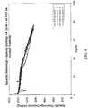
- the cells were discharged at 3.2 mA (0.0965 mA/cm 2 ) from 2.5 V to 1.7 V and charged at 2 mA (0.0603 mA/cm 2 ) from 1.7 V to 2.5 V. Cycling results are illustrated in FIG. 3 .
- the cathode had an RMS surface roughness of 0.2 micrometers, and the cells were able to achieve a capacity of 1000 mAh/g. The capacity of the cells tapered slowly to 800 mAh/g over 20 cycles (as opposed to dropping significantly in capacity as seen with other amorphous carbons).
- the wet compressed cathode had a lower RMS surface roughness than the dry compressed cathode, cells including the wet compressed cathodes exhibited similar discharge capacities.
- Electrochemical cells were assembled and tested as described in Example 1, except no pressure was applied to the cathode composition prior to integrating the cathodes into the electrochemical cells.
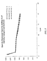
- the electrochemical cells that included non-compressed cathodes were electrochemically cycled. During charge and discharge, an anisotropic force defining a pressure of 98 Newtons/cm 2 (10 kg f /cm 2 ) was applied to the cells. Charge and discharge performance was then measured. For the first two cycles, the electrochemical cells were discharged at 4 mA (0.0402 mA/cm 2 ) from 2.5 V to 1.7 V. For the 3rd and subsequent cycles, the electrochemical cells were discharged at 40 mA (0.4022 mA/cm 2 ) from 2.5 V to 1.7 V. For all cycles, charging was performed at 25 mA (0.2514 mA/cm 2 ) from 1.7 V to 2.5 V. Cycling results are illustrated in FIG. 4 . While the as-coated cathode exhibited a higher specific capacity than the compressed cathodes, the high RMS surface roughness of these electrodes damaged other components in the cell.
- This example illustrates the benefit of including a liquid wetting agent when compressing an electrode precursor composition to form an electrode.
- Electrode compositions were formed as described in Example 1. After the compositions had been formed, one set of electrode compositions (“Soaked Electrodes”) was soaked between two wet, lint-free wipes then removed from the wet wipes prior to applying compression as described in Example 1. Another set of electrode compositions (“Dry Electrodes”) were compressed as coated without any additional processing prior to compressing.
- the dry, compressed cathodes were smoother than cathodes to which no pressure was applied, the dry, compressed cathodes of this example were not as smooth (having RMS surface roughness values between 1.8 micrometers and 2.4 micrometers) as those described in Example 1 (which had RMS surface roughness values between 1.2 micrometers and 1.6 micrometers). In addition, the dry, compressed cathodes exhibited much more cracking than the wet, compressed cathodes.
- the dry, compressed cathodes were incorporated into electrochemical cells as described in Example 1 and electrochemically cycled. During charge and discharge, an anisotropic force defining a pressure of 98 Newtons/cm 2 (10 kg f /cm 2 ) was applied to the cells. Charge and discharge performance was then measured. During the first cycle, the cells were discharged at 1.3 mA (0.0392 mA/cm 2 ) from 2.5 V to 1.7 V. During the 2nd and subsequent cycles, the cells were discharged at 3.2 mA (0.0965 mA/cm 2 ) from 2.5 V to 1.7 V. For all cycles, the cells were charged at 3 mA (0.0905 mA/cm 2 ) from 1.7 V to 2.5 V. Cycling results are illustrated in FIG. 5 . The dry and wet compressed cathodes showed similar performance, with the wet compressed cathodes being smoother (and thus, less capable of damaging other cell components).
- This example illustrates the reduction in performance that occurs when particulate electronically conductive material capable of maintaining its porosity under large applied pressures is replaced with particulate electronically conductive material that collapses under large applied pressures when forming an electrode.
- Electrode compositions were formed as described in Example 1. However, rather than using Porocarb® HD3 porous carbon, amorphous carbon black was used as the particulate electronically conductive material. In one set of electrodes (corresponding to "Carbon 1" in FIG. 6 ), XE2 and Vulcan carbon black materials were used. In another set of electrodes (corresponding to "Carbon 2" in FIG. 6 ), Vulcan carbon black was used. The electrode compositions were compressed (while wet) to form electrodes including 55 wt% sulfur, 40 wt% carbon(s), and 5 wt % PVOH binder, and the electrodes were assembled into electrochemical cells, as described in Example 1. The resulting cells were electrochemically cycled.
- the capacities of the cells dropped.
- the cells continued to cycle below 700 mAh/g and were stopped at the 21st cycle.
- the discharge rate was modified at the 15th cycle, which resulted in an increase in capacity; however, when the discharge rate was changed back at the 16th cycle (to 40 mAh/g the capacity again dropped.
- a reference to "A and/or B,” when used in conjunction with open-ended language such as “comprising” can refer, in one embodiment, to A without B (optionally including elements other than B); in another embodiment, to B without A (optionally including elements other than A); in yet another embodiment, to both A and B (optionally including other elements); etc.
- the phrase "at least one,” in reference to a list of one or more elements, should be understood to mean at least one element selected from any one or more of the elements in the list of elements, but not necessarily including at least one of each and every element specifically listed within the list of elements and not excluding any combinations of elements in the list of elements.
- This definition also allows that elements may optionally be present other than the elements specifically identified within the list of elements to which the phrase "at least one" refers, whether related or unrelated to those elements specifically identified.
- At least one of A and B can refer, in one embodiment, to at least one, optionally including more than one, A, with no B present (and optionally including elements other than B); in another embodiment, to at least one, optionally including more than one, B, with no A present (and optionally including elements other than A); in yet another embodiment, to at least one, optionally including more than one, A, and at least one, optionally including more than one, B (and optionally including other elements); etc.
Landscapes
- Chemical & Material Sciences (AREA)
- Chemical Kinetics & Catalysis (AREA)
- Electrochemistry (AREA)
- General Chemical & Material Sciences (AREA)
- Engineering & Computer Science (AREA)
- Manufacturing & Machinery (AREA)
- Materials Engineering (AREA)
- Inorganic Chemistry (AREA)
- Battery Electrode And Active Subsutance (AREA)
- Secondary Cells (AREA)
Claims (15)
- Verfahren zur Herstellung einer Elektrode, umfassend:Aufwendung eines Drucks von mindestens etwa 590 Newton/cm2 auf eine Zusammensetzung enthaltend ein partikelförmiges, elektrisch leitfähiges Material, ein aktives Elektrodenmaterial, ein Bindemittel und ein flüssiges Benetzungsmittel zur Bildung der Elektrode,wobei nach Aufwendung des Drucks auf die Zusammensetzung die Elektrode eine Porosität von mindestens etwa 40 % aufweist.
- Verfahren gemäß Anspruch 1, wobei das flüssige Benetzungsmittel ein organisches Lösungsmittel und/oder Wasser enthält.
- Verfahren gemäß einem der Ansprüche 1 bis 2, umfassend die Aufwendung eines Drucks von mindestens etwa 590 Newton/cm2 und bis zu etwa 6000 Newton/cm2 auf die Zusammensetzung, oder
umfassend die Aufwendung eines Drucks von mindestens etwa 750 Newton/cm2 auf die Zusammensetzung, oder
umfassend die Aufwendung eines Drucks von mindestens etwa 1000 Newton/cm2 auf die Zusammensetzung. - Verfahren gemäß einem der Ansprüche 1 bis 3, umfassend die Aufwendung eines Drucks von mindestens etwa 1765 Newton/cm2 auf die Zusammensetzung.
- Verfahren gemäß Anspruch 4, umfassend die Aufwendung eines Drucks von mindestens etwa 1765 Newton/cm2 und bis zu etwa 6000 Newton/cm2 auf die Zusammensetzung.
- Verfahren gemäß einem der Ansprüche 1 bis 5, wobei das partikelförmige, elektrisch leitfähige Material Kohlenstoff, vorzugsweise Ruß, enthält.
- Verfahren gemäß einem der Ansprüche 1 bis 6, wobei das partikelförmige, elektrisch leitfähige Material einen spezifischen elektrischen Widerstand von weniger als etwa 10-3 Ohm-m bei 20 °C aufweist, und/oder
wobei das aktive Elektrodenmaterial Schwefel, vorzugsweise elementaren Schwefel, enthält, und/oder
wobei das Bindemittel ein polymeres Bindemittel, vorzugsweise Polyvinylalkohol, enthält. - Verfahren gemäß einem der Ansprüche 1 bis 7, wobei nach Aufwendung des Drucks auf die Zusammensetzung die Elektrode eine Porosität von mindestens etwa 40 % und bis zu etwa 70 % aufweist, und/oder
wobei die Dicke der Elektrode weniger als oder etwa gleich 1 mm beträgt, vorzugsweise
wobei die Dicke der Elektrode mindestens etwa 10 Mikrometer und weniger als oder etwa gleich 1 mm beträgt, und/oder
wobei das partikelförmige, elektrisch leitfähige Material porös ist. - Verfahren gemäß einem der Ansprüche 1 bis 8, umfassend die zumindest teilweise Entfernung des flüssigen Benetzungsmittels aus der Zusammensetzung zur Bildung der Elektrode, wobei das flüssige Benetzungsmittel zumindest teilweise entfernt wird, nachdem Druck auf die Zusammensetzung aufgewendet wurde.
- Eine Elektrode, enthaltend:ein partikelförmiges, elektrisch leitfähiges Material;ein aktives Elektrodenmaterial; undein Bindemittel, wobei:die Elektrode eine Porosität von mindestens etwa 40 % aufweist,das partikelförmige, elektrisch leitfähige Material einen spezifischen elektrischen Widerstand von weniger als etwa 10-3 Ohm-m bei 20 °C aufweist und
eine externe geometrische Oberfläche der Elektrode eine Oberflächenrauheit mit einem Effektivwert von weniger als etwa 15 Mikrometern über einen geometrischen Oberflächenbereich von mindestens etwa 10.000 Quadratmikrometern aufweist. - Die Elektrode gemäß Anspruch 10, wobei das partikelförmige, elektrisch leitfähige Material porös ist, und/oder
wobei das partikelförmige, elektrisch leitfähige Material Kohlenstoff, vorzugsweise Ruß, enthält. - Die Elektrode gemäß einem der Ansprüche 10 bis 11, wobei das aktive Elektrodenmaterial Schwefel, vorzugsweise elementaren Schwefel, enthält, und/oder
wobei das Bindemittel ein polymeres Bindemittel, vorzugsweise Polyvinylalkohol, enthält. - Die Elektrode gemäß einem der Ansprüche 10 bis 12, wobei die Elektrode eine Porosität von mindestens etwa 40 % und bis zu etwa 70 % aufweist, und/oder
wobei die Dicke der Elektrode weniger als etwa 1 mm beträgt, vorzugsweise
wobei die Dicke der Elektrode mindestens etwa 10 Mikrometer und weniger als oder etwa gleich 1 mm beträgt, und/oder
wobei die externe geometrische Oberfläche der Elektrode eine Oberflächenrauheit mit einem Effektivwert von etwa 0,1 Mikrometern bis etwa 15 Mikrometern aufweist. - Eine elektrochemische Zelle enthaltend die Elektrode gemäß einem der Ansprüche 10 bis 13.
- Die elektrochemische Zelle gemäß Anspruch 14, enthaltend eine zweite Elektrode, die Lithium, vorzugsweise Lithiummetall und/oder eine Lithiumlegierung, enthält.
Applications Claiming Priority (2)
| Application Number | Priority Date | Filing Date | Title |
|---|---|---|---|
| US201461987271P | 2014-05-01 | 2014-05-01 | |
| PCT/EP2015/059479 WO2015166030A1 (en) | 2014-05-01 | 2015-04-30 | Electrode fabrication methods and associated articles |
Publications (2)
| Publication Number | Publication Date |
|---|---|
| EP3138144A1 EP3138144A1 (de) | 2017-03-08 |
| EP3138144B1 true EP3138144B1 (de) | 2018-07-25 |
Family
ID=53039905
Family Applications (1)
| Application Number | Title | Priority Date | Filing Date |
|---|---|---|---|
| EP15720078.3A Active EP3138144B1 (de) | 2014-05-01 | 2015-04-30 | Verfahren zur herstellung von elektroden, sowie hergestellte artikel |
Country Status (6)
| Country | Link |
|---|---|
| US (2) | US9711784B2 (de) |
| EP (1) | EP3138144B1 (de) |
| JP (1) | JP2017515277A (de) |
| KR (1) | KR102622781B1 (de) |
| CN (1) | CN106256034B (de) |
| WO (1) | WO2015166030A1 (de) |
Families Citing this family (48)
| Publication number | Priority date | Publication date | Assignee | Title |
|---|---|---|---|---|
| CN103283064B (zh) | 2010-08-24 | 2017-07-11 | 锡安能量公司 | 用于在电化学电池中使用的电解质材料 |
| US9577289B2 (en) | 2012-12-17 | 2017-02-21 | Sion Power Corporation | Lithium-ion electrochemical cell, components thereof, and methods of making and using same |
| CN106256034B (zh) | 2014-05-01 | 2019-04-23 | 锡安能量公司 | 电极制造方法及相关制品 |
| EP3298643B1 (de) | 2015-05-21 | 2019-06-12 | Basf Se | Glaskeramik-elektrolyten für lithium-schwefel-batterien |
| US10320031B2 (en) | 2015-11-13 | 2019-06-11 | Sion Power Corporation | Additives for electrochemical cells |
| KR20180077287A (ko) | 2015-11-24 | 2018-07-06 | 시온 파워 코퍼레이션 | 이온 전도성 화합물 및 관련 용도 |
| WO2017197299A1 (en) * | 2016-05-12 | 2017-11-16 | Navitas Systems, Llc | Compositions and methods for electrode fabrication |
| US10991925B2 (en) | 2016-06-21 | 2021-04-27 | Sion Power Corporation | Coatings for components of electrochemical cells |
| WO2018119392A1 (en) | 2016-12-23 | 2018-06-28 | Sion Power Corporation | Protective layers comprising metals for electrochemical cells |
| US11024923B2 (en) | 2017-03-09 | 2021-06-01 | Sion Power Corporation | Electrochemical cells comprising short-circuit resistant electronically insulating regions |
| WO2018170413A1 (en) | 2017-03-17 | 2018-09-20 | Sion Power Corporation | Electrode edge protection in electrochemical cells |
| US10868306B2 (en) | 2017-05-19 | 2020-12-15 | Sion Power Corporation | Passivating agents for electrochemical cells |
| KR102664549B1 (ko) | 2017-05-19 | 2024-05-09 | 시온 파워 코퍼레이션 | 전기화학 전지용 부동태화제 |
| KR20200000849A (ko) | 2017-05-24 | 2020-01-03 | 시온 파워 코퍼레이션 | 이온 전도성 화합물 및 관련 용도 |
| CN110710048B (zh) | 2017-06-09 | 2023-03-07 | 赛昂能源有限公司 | 原位集流体 |
| KR102167119B1 (ko) | 2017-07-20 | 2020-10-16 | 주식회사 엘지화학 | 이차전지용 전극 제조시스템 및 제조방법 |
| KR102142551B1 (ko) | 2017-07-20 | 2020-08-07 | 주식회사 엘지화학 | 이차전지용 전극 제조시스템 및 제조방법 |
| US12113208B2 (en) | 2017-09-15 | 2024-10-08 | Sion Power Corporation | Protective membrane for electrochemical cells |
| US11081731B2 (en) * | 2017-10-18 | 2021-08-03 | International Business Machines Corporation | High-capacity rechargeable batteries |
| CN120527342A (zh) | 2018-01-11 | 2025-08-22 | 株式会社Lg新能源 | 正极浆料组合物、使用所述正极浆料组合物制造的正极和包含所述正极的电池 |
| US11175561B1 (en) | 2018-04-12 | 2021-11-16 | E Ink Corporation | Electrophoretic display media with network electrodes and methods of making and using the same |
| KR102744769B1 (ko) * | 2018-04-13 | 2024-12-18 | 나비타스 시스템즈, 엘엘씨 | 전극 제작을 위한 조성물 및 방법 |
| JP7680350B2 (ja) | 2018-07-31 | 2025-05-20 | シオン・パワー・コーポレーション | 多重化された充電放電バッテリ管理システム |
| US11637353B2 (en) | 2018-12-27 | 2023-04-25 | Sion Power Corporation | Electrodes, heaters, sensors, and associated articles and methods |
| US11322804B2 (en) | 2018-12-27 | 2022-05-03 | Sion Power Corporation | Isolatable electrodes and associated articles and methods |
| WO2020139802A2 (en) | 2018-12-27 | 2020-07-02 | Sion Power Corporation | Electrochemical devices and related articles, components, configurations, and methods |
| EP3973583A1 (de) | 2019-05-22 | 2022-03-30 | Sion Power Corporation | Elektrisch gekoppelte elektroden und zugehörige gegenstände und verfahren |
| US11710828B2 (en) | 2019-05-22 | 2023-07-25 | Sion Power Corporation | Electrochemical devices including porous layers |
| CN114128024A (zh) | 2019-06-21 | 2022-03-01 | 赛昂能源有限公司 | 用于向电化学装置施加力的方法、系统和装置 |
| US11424492B2 (en) | 2019-10-31 | 2022-08-23 | Sion Power Corporation | System and method for operating a rechargeable electrochemical cell or battery |
| US11056728B2 (en) | 2019-10-31 | 2021-07-06 | Sion Power Corporation | System and method for operating a rechargeable electrochemical cell or battery |
| US11791511B2 (en) | 2019-11-19 | 2023-10-17 | Sion Power Corporation | Thermally insulating compressible components for battery packs |
| US11978917B2 (en) | 2019-11-19 | 2024-05-07 | Sion Power Corporation | Batteries with components including carbon fiber, and associated systems and methods |
| JP2023502993A (ja) | 2019-11-19 | 2023-01-26 | シオン・パワー・コーポレーション | 電池ならびに関連するシステムおよび方法 |
| US11984575B2 (en) | 2019-11-19 | 2024-05-14 | Sion Power Corporation | Battery alignment, and associated systems and methods |
| US20210193996A1 (en) | 2019-12-20 | 2021-06-24 | Sion Power Corporation | Lithium metal electrodes |
| EP4078717A1 (de) | 2019-12-20 | 2022-10-26 | Sion Power Corporation | Systeme und verfahren zum bereitstellen, zusammenbauen und verwalten eines integrierten strombusses für eine wiederaufladbare elektrochemische zelle oder batterie |
| EP4118701A1 (de) * | 2020-03-13 | 2023-01-18 | Sion Power Corporation | Anwendung von druck auf elektrochemische vorrichtungen mit verformbaren feststoffen und zugehörige systeme |
| EP4189763A1 (de) | 2020-08-03 | 2023-06-07 | Sion Power Corporation | Elektrochemische zellklemmen und zugehörige verfahren |
| US11826861B1 (en) | 2020-08-12 | 2023-11-28 | Sion Power Corporation | Joining systems, clamping fixtures, and related systems and methods |
| US12580394B2 (en) * | 2020-09-01 | 2026-03-17 | Sion Power Corporation | Multiplexed battery management system |
| US11705554B2 (en) | 2020-10-09 | 2023-07-18 | Sion Power Corporation | Electrochemical cells and/or components thereof comprising nitrogen-containing species, and methods of forming them |
| WO2022081325A1 (en) | 2020-10-13 | 2022-04-21 | Sion Power Corporation | Electrolytes for lithium batteries |
| JP2023545469A (ja) | 2020-10-14 | 2023-10-30 | シオン・パワー・コーポレーション | ガス発生を低減するための電解質 |
| US12040474B2 (en) * | 2020-11-13 | 2024-07-16 | Licap Technologies, Inc. | Dry electrode manufacture with composite binder |
| US12374913B2 (en) | 2021-02-05 | 2025-07-29 | Sion Power Corporation | Charge/discharge management in electrochemical cells, including partial cycle control |
| KR20230167411A (ko) | 2021-04-08 | 2023-12-08 | 시온 파워 코퍼레이션 | 리튬 배터리용 전해액 |
| US12278357B2 (en) | 2021-07-23 | 2025-04-15 | Sion Power Corporation | Battery module with multiplexing and associated systems and methods |
Family Cites Families (230)
| Publication number | Priority date | Publication date | Assignee | Title |
|---|---|---|---|---|
| BE634204A (de) | 1962-06-27 | 1900-01-01 | ||
| US3716409A (en) | 1971-09-08 | 1973-02-13 | Atomic Energy Commission | Cathodes for secondary electrochemical power-producing cells |
| BE793984A (fr) | 1972-01-14 | 1973-05-02 | Foseco Int | Nouvelle fabrication de produits ceramiques poreux |
| US3833421A (en) | 1972-12-27 | 1974-09-03 | Atomic Energy Commission | Secondary electrochemical cells with a chalcogen cathode |
| GB1396062A (en) | 1973-07-12 | 1975-05-29 | Comp Generale Electricite | Rechargeable solid state electro-chemical cell having a lithium anode and a method of manufacturing the same |
| US3859139A (en) | 1974-01-11 | 1975-01-07 | United Aircraft Corp | Novel composite fuel cell electrode |
| US3951689A (en) | 1975-08-20 | 1976-04-20 | Ford Motor Company | Alkali metal/sulfur cell with gas fuel cell electrode |
| US4011374A (en) | 1975-12-02 | 1977-03-08 | The United States Of America As Represented By The United States Energy Research And Development Administration | Porous carbonaceous electrode structure and method for secondary electrochemical cell |
| JPS5289341A (en) | 1976-01-20 | 1977-07-26 | Sharp Corp | Indication device |
| US4184013A (en) | 1976-07-24 | 1980-01-15 | Brown, Boveri & Cie Ag | Electrochemical storage cell |
| US4169120A (en) | 1976-12-15 | 1979-09-25 | Great Lakes Carbon Corporation | Sulfur electrode for sodium-sulfur batteries |
| DE3026065A1 (de) | 1980-07-10 | 1982-02-04 | Varta Batterie Ag, 3000 Hannover | Wiederaufladbares galvanisches element |
| IL61085A (en) | 1980-09-19 | 1983-07-31 | Univ Ramot | Nonaqueous sulfur cell |
| US4339325A (en) | 1980-10-31 | 1982-07-13 | Diamond Shamrock Corporation | One pass process for forming electrode backing sheet |
| US4337140A (en) | 1980-10-31 | 1982-06-29 | Diamond Shamrock Corporation | Strengthening of carbon black-teflon-containing electrodes |
| US4419424A (en) * | 1981-07-14 | 1983-12-06 | Julian John D | Electrodes for electrochemical cells current generating cells and rechargeable accumulators |
| US4720400A (en) | 1983-03-18 | 1988-01-19 | W. L. Gore & Associates, Inc. | Microporous metal-plated polytetrafluoroethylene articles and method of manufacture |
| US4624902A (en) | 1983-06-27 | 1986-11-25 | Voltaix, Incorporated | Coatings for electrochemical electrodes and methods of making the same |
| BR8407077A (pt) | 1983-09-20 | 1985-08-13 | Elf Aquitaine | Novos derivados de sulfetos de policarbono,sua preparacao e suas aplicacoes,especialmente em eletroquimica |
| US4556618A (en) | 1983-12-01 | 1985-12-03 | Allied Corporation | Battery electrode and method of making |
| FR2570882B1 (fr) | 1984-09-21 | 1986-12-05 | Comp Generale Electricite | Matiere active positive a base d'un polymere conducteur electronique pour generateur electrochimique |
| US4677415A (en) | 1985-05-08 | 1987-06-30 | Motorola, Inc. | Ceramic humidity sensor |
| US4689544A (en) | 1985-10-17 | 1987-08-25 | Hughes Aircraft Company | Control of the charging of pressurized gas-metal electrical storage cells |
| DE3615240A1 (de) | 1986-05-06 | 1987-11-12 | Bbc Brown Boveri & Cie | Elektrochemische speicherzelle |
| US4833048A (en) | 1988-03-31 | 1989-05-23 | The United States Of America As Represented By The United States Department Of Energy | Metal-sulfur type cell having improved positive electrode |
| USH858H (en) | 1988-10-24 | 1990-12-04 | The United States Of America As Represented By The Secretary Of The Air Force | Electrical battery cell wicking structure and method |
| US5126082A (en) | 1988-11-30 | 1992-06-30 | Howmet Corporation | Method of making ceramic cores and other articles |
| US4917974A (en) | 1989-04-14 | 1990-04-17 | The United States Of America As Represented By The Department Of Energy | Lithium/organosulfur redox cell having protective solid electrolyte barrier formed on anode and method of making same |
| US5162175A (en) | 1989-10-13 | 1992-11-10 | Visco Steven J | Cell for making secondary batteries |
| US5108852A (en) * | 1990-03-23 | 1992-04-28 | Battery Technologies Inc. | Manganese dioxide cathode for a rechargeable alkaline cell, and cell containing the same |
| US5324599A (en) | 1991-01-29 | 1994-06-28 | Matsushita Electric Industrial Co., Ltd. | Reversible electrode material |
| JPH05266879A (ja) | 1991-05-08 | 1993-10-15 | Unitika Ltd | 複合電極及び電池 |
| US5328946A (en) | 1991-08-29 | 1994-07-12 | E. I. Du Pont De Nemours And Company | Solvents for tetrafluoroethylene polymers |
| US5194341A (en) | 1991-12-03 | 1993-03-16 | Bell Communications Research, Inc. | Silica electrolyte element for secondary lithium battery |
| US5895732A (en) | 1992-04-24 | 1999-04-20 | Ensci, Inc. | Battery element containing macroporous additives |
| US5290414A (en) | 1992-05-15 | 1994-03-01 | Eveready Battery Company, Inc. | Separator/electrolyte combination for a nonaqueous cell |
| JPH05325978A (ja) | 1992-05-20 | 1993-12-10 | Shin Kobe Electric Mach Co Ltd | アルカリ蓄電池用ニッケル焼結基板及びその製造方法 |
| JP3232710B2 (ja) | 1992-10-08 | 2001-11-26 | 松下電器産業株式会社 | 非水電解液二次電池の製造方法 |
| US5441831A (en) | 1992-12-17 | 1995-08-15 | Associated Universities, Inc. | Cells having cathodes containing polycarbon disulfide materials |
| US5460905A (en) | 1993-06-16 | 1995-10-24 | Moltech Corporation | High capacity cathodes for secondary cells |
| US5433917A (en) | 1993-09-16 | 1995-07-18 | The Penn State Research Foundation | PZT ceramic compositions having reduced sintering temperatures and process for producing same |
| US5538812A (en) | 1994-02-04 | 1996-07-23 | Moltech Corporation | Electrolyte materials containing highly dissociated metal ion salts |
| US5648187A (en) | 1994-02-16 | 1997-07-15 | Moltech Corporation | Stabilized anode for lithium-polymer batteries |
| US5961672A (en) | 1994-02-16 | 1999-10-05 | Moltech Corporation | Stabilized anode for lithium-polymer batteries |
| US5516598A (en) | 1994-07-28 | 1996-05-14 | Polyplus Battery Company, Inc. | Secondary cell using organosulfur/metal charge transfer materials as positive electrode |
| JP3261688B2 (ja) | 1994-08-23 | 2002-03-04 | キヤノン株式会社 | 二次電池及びその製造方法 |
| JP3717085B2 (ja) | 1994-10-21 | 2005-11-16 | キヤノン株式会社 | 二次電池用負極、該負極を有する二次電池及び電極の作製方法 |
| US5814420A (en) | 1994-11-23 | 1998-09-29 | Polyplus Battery Company, Inc. | Rechargeable positive electrodes |
| US5686201A (en) | 1994-11-23 | 1997-11-11 | Polyplus Battery Company, Inc. | Rechargeable positive electrodes |
| US5582623A (en) | 1994-11-23 | 1996-12-10 | Polyplus Battery Company, Inc. | Methods of fabricating rechargeable positive electrodes |
| US6358643B1 (en) | 1994-11-23 | 2002-03-19 | Polyplus Battery Company | Liquid electrolyte lithium-sulfur batteries |
| US6030720A (en) | 1994-11-23 | 2000-02-29 | Polyplus Battery Co., Inc. | Liquid electrolyte lithium-sulfur batteries |
| JPH08213026A (ja) | 1994-11-28 | 1996-08-20 | Katayama Tokushu Kogyo Kk | 電池電極基板用金属多孔体、電池電極板およびその製造方法 |
| US5723230A (en) | 1995-02-27 | 1998-03-03 | Yazaki Corporation | Oligosulfide type electrode material and secondary battery containing such electrode material |
| US5529860A (en) | 1995-06-07 | 1996-06-25 | Moltech Corporation | Electroactive high storage capacity polyacetylene-co-polysulfur materials and electrolytic cells containing same |
| US5601947A (en) | 1995-06-07 | 1997-02-11 | Moltech Corporation | Electroactive high storage capacity polycarbon-sulfide materials and electrolytic cells containing same |
| AU5882896A (en) | 1995-06-07 | 1996-12-30 | Moltech Corporation | Electroactive high storage capacity polyacetylene-co-polysul fur materials and electrolytic cells containing same |
| US5643512A (en) | 1995-08-16 | 1997-07-01 | Northrop Grumman Corporation | Methods for producing ceramic foams using pre-ceramic resins combined with liquid phenolic resin |
| US5792575A (en) | 1995-09-11 | 1998-08-11 | Yazaki Corporation | Lithium sulfur secondary battery and elecrode material for a non-aqueous battery |
| JP3555097B2 (ja) | 1995-09-28 | 2004-08-18 | 矢崎総業株式会社 | 電極材料及び二次電池 |
| JP3525403B2 (ja) | 1995-09-28 | 2004-05-10 | 矢崎総業株式会社 | 電極材料及び二次電池 |
| JP3407501B2 (ja) | 1995-09-29 | 2003-05-19 | 松下電器産業株式会社 | ポリマ電解質およびそれを用いたリチウム・ポリマ電池 |
| JPH09147868A (ja) | 1995-11-17 | 1997-06-06 | Yazaki Corp | スルフィド系二次電池及び電極材用活性炭素繊維 |
| DE19611510A1 (de) | 1996-03-23 | 1997-09-25 | Degussa | Gasdiffusionselektrode für Membranbrennstoffzellen und Verfahren zu ihrer Herstellung |
| JP2000511342A (ja) | 1996-05-22 | 2000-08-29 | モルテック コーポレイション | 複合カソード、新規複合カソードを含む化学電池、およびそれらを製造するプロセス |
| US6168886B1 (en) | 1996-07-02 | 2001-01-02 | Ensci Inc | Battery element containing metal macroporous additives |
| US6403261B2 (en) | 1996-07-31 | 2002-06-11 | Valentin Nikolaevich Mitkin | Carbon-containing material and a method of making porous electrodes for chemical sources of electric current |
| JP3253859B2 (ja) * | 1996-08-09 | 2002-02-04 | 東芝電池株式会社 | 非水溶媒二次電池およびその負極合剤の造粒方法 |
| JPH1055823A (ja) | 1996-08-12 | 1998-02-24 | Shin Kobe Electric Mach Co Ltd | 電 池 |
| CA2248303C (fr) | 1996-12-30 | 2010-05-25 | Hydro-Quebec | Sels d'amides perfluores, et leurs utilisations comme materiaux a conduction ionique |
| US5882812A (en) | 1997-01-14 | 1999-03-16 | Polyplus Battery Company, Inc. | Overcharge protection systems for rechargeable batteries |
| JP3619000B2 (ja) * | 1997-01-28 | 2005-02-09 | キヤノン株式会社 | 電極構造体、二次電池及びそれらの製造方法 |
| US6432585B1 (en) | 1997-01-28 | 2002-08-13 | Canon Kabushiki Kaisha | Electrode structural body, rechargeable battery provided with said electrode structural body, and rechargeable battery |
| JPH10214638A (ja) | 1997-01-30 | 1998-08-11 | Hitachi Ltd | リチウム二次電池 |
| US6171723B1 (en) | 1997-10-10 | 2001-01-09 | 3M Innovative Properties Company | Batteries with porous components |
| JPH11121045A (ja) | 1997-10-17 | 1999-04-30 | Japan Storage Battery Co Ltd | 非水電解質二次電池 |
| JPH11219731A (ja) | 1997-11-27 | 1999-08-10 | Sony Corp | 有機電解質二次電池 |
| JP4095145B2 (ja) | 1997-12-09 | 2008-06-04 | Tdk株式会社 | 電極の製造方法 |
| US6194099B1 (en) | 1997-12-19 | 2001-02-27 | Moltech Corporation | Electrochemical cells with carbon nanofibers and electroactive sulfur compounds |
| US6110619A (en) | 1997-12-19 | 2000-08-29 | Moltech Corporation | Electrochemical cells with cationic polymers and electroactive sulfur compounds |
| US6201100B1 (en) | 1997-12-19 | 2001-03-13 | Moltech Corporation | Electroactive, energy-storing, highly crosslinked, polysulfide-containing organic polymers and methods for making same |
| US6153337A (en) | 1997-12-19 | 2000-11-28 | Moltech Corporation | Separators for electrochemical cells |
| US6528211B1 (en) | 1998-03-31 | 2003-03-04 | Showa Denko K.K. | Carbon fiber material and electrode materials for batteries |
| IL124007A (en) | 1998-04-08 | 2001-08-26 | Univ Ramot | Long cycle-life alkali metal battery |
| US6492064B1 (en) | 1998-06-04 | 2002-12-10 | California Institute Of Technology | Organic solvents, electrolytes, and lithium ion cells with good low temperature performance |
| JP3403090B2 (ja) | 1998-09-18 | 2003-05-06 | キヤノン株式会社 | 多孔質構造の金属酸化物、電極構造体、二次電池及びこれらの製造方法 |
| US6759170B2 (en) | 1998-10-22 | 2004-07-06 | Wilson Greatbatch Technologies, Inc. | Organic carbonate additives for nonaqueous electrolyte rechargeable electrochemical cells |
| US6110621A (en) | 1998-11-24 | 2000-08-29 | The University Of Chicago | Carbons for lithium batteries prepared using sepiolite as an inorganic template |
| US6302928B1 (en) | 1998-12-17 | 2001-10-16 | Moltech Corporation | Electrochemical cells with high volumetric density of electroactive sulfur-containing materials in cathode active layers |
| US6168694B1 (en) | 1999-02-04 | 2001-01-02 | Chemat Technology, Inc. | Methods for and products of processing nanostructure nitride, carbonitride and oxycarbonitride electrode power materials by utilizing sol gel technology for supercapacitor applications |
| US6225002B1 (en) | 1999-02-05 | 2001-05-01 | Polyplus Battery Company, Inc. | Dioxolane as a proctector for lithium electrodes |
| DE19910968A1 (de) | 1999-03-12 | 2000-11-09 | Merck Patent Gmbh | Anwendung von Additiven in Elektrolyten für elektrochemische Zellen |
| JP2000268873A (ja) | 1999-03-12 | 2000-09-29 | Sumitomo Electric Ind Ltd | リチウム二次電池とそれを用いた電池装置 |
| US6680013B1 (en) | 1999-04-15 | 2004-01-20 | Regents Of The University Of Minnesota | Synthesis of macroporous structures |
| JP2000311679A (ja) * | 1999-04-26 | 2000-11-07 | Sumitomo Metal Ind Ltd | 含浸による電池用極板の製造方法 |
| JP3940546B2 (ja) | 1999-06-07 | 2007-07-04 | 株式会社東芝 | パターン形成方法およびパターン形成材料 |
| JP2001093577A (ja) | 1999-09-20 | 2001-04-06 | Toyota Central Res & Dev Lab Inc | リチウム二次電池 |
| US7354675B2 (en) | 1999-10-07 | 2008-04-08 | Proton Energy Systems, Inc. | Apparatus and method for maintaining compression of the active area in an electrochemical cell |
| JP2001143757A (ja) | 1999-11-11 | 2001-05-25 | Nec Mobile Energy Kk | 密閉型電池 |
| WO2001036206A1 (en) | 1999-11-12 | 2001-05-25 | Fargo Electronics, Inc. | Thermal printhead compensation |
| US7247408B2 (en) | 1999-11-23 | 2007-07-24 | Sion Power Corporation | Lithium anodes for electrochemical cells |
| US20070221265A1 (en) | 2006-03-22 | 2007-09-27 | Sion Power Corporation | Rechargeable lithium/water, lithium/air batteries |
| US6528033B1 (en) | 2000-01-18 | 2003-03-04 | Valence Technology, Inc. | Method of making lithium-containing materials |
| US7001690B2 (en) | 2000-01-18 | 2006-02-21 | Valence Technology, Inc. | Lithium-based active materials and preparation thereof |
| JP2001345106A (ja) | 2000-03-31 | 2001-12-14 | Japan Storage Battery Co Ltd | 燃料電池用電極およびその製造方法 |
| JP4529274B2 (ja) | 2000-04-18 | 2010-08-25 | ソニー株式会社 | 非水電解質電池 |
| US20040047798A1 (en) | 2000-05-24 | 2004-03-11 | Oh Seung Mo | Mesoporous carbon material, carbon/metal oxide composite materials, and electrochemical capacitors using them |
| EP1164651A1 (de) | 2000-06-12 | 2001-12-19 | Asahi Glass Co., Ltd. | Elektrodenkatalysator für Festpolymerelektrolytbrennstoffzelle und Verfahren zu dessen Herstellung |
| US6544688B1 (en) | 2000-09-20 | 2003-04-08 | Moltech Corporation | Cathode current collector for electrochemical cells |
| US7553584B2 (en) | 2000-10-20 | 2009-06-30 | Massachusetts Institute Of Technology | Reticulated and controlled porosity battery structures |
| KR100378007B1 (ko) | 2000-11-22 | 2003-03-29 | 삼성에스디아이 주식회사 | 리튬-황 전지용 양극 및 그를 포함하는 리튬-황 전지 |
| KR100385357B1 (ko) | 2001-06-01 | 2003-05-27 | 삼성에스디아이 주식회사 | 리튬-황 전지 |
| DE10128970A1 (de) | 2001-06-15 | 2002-12-19 | Fortu Bat Batterien Gmbh | Bei Normaltemperatur betreibbare, wiederaufladbare Batteriezelle |
| US6753036B2 (en) | 2001-07-16 | 2004-06-22 | The Regents Of The University Of California | Method for fabrication of electrodes |
| CA2455819C (en) | 2001-07-27 | 2013-07-23 | Massachusetts Institute Of Technology | Battery structures, self-organizing structures and related methods |
| KR100396492B1 (ko) | 2001-10-17 | 2003-09-02 | 삼성에스디아이 주식회사 | 리튬-황 전지용 양극 활물질 및 이를 포함하는 양극활물질 조성물의 제조 방법 |
| US7005214B2 (en) | 2001-11-02 | 2006-02-28 | Wilson Greatbatch Technologies, Inc. | Noble metals coated on titanium current collectors for use in nonaqueous Li/CFx cells |
| US20030108785A1 (en) | 2001-12-10 | 2003-06-12 | Wu L. W. | Meso-porous carbon and hybrid electrodes and method for producing the same |
| US20030113622A1 (en) | 2001-12-14 | 2003-06-19 | Blasi Jane A. | Electrolyte additive for non-aqueous electrochemical cells |
| KR100436712B1 (ko) | 2001-12-19 | 2004-06-22 | 삼성에스디아이 주식회사 | 캐소드 전극, 그 제조방법 및 이를 채용한 리튬 전지 |
| JP3937839B2 (ja) | 2001-12-28 | 2007-06-27 | 日本電気株式会社 | モジュール |
| CA2367290A1 (fr) | 2002-01-16 | 2003-07-16 | Hydro Quebec | Electrolyte polymere a haute stabilite > 4 volts comme electrolyte pour supercondensateur hybride et generateur electrochimique |
| JP3897709B2 (ja) | 2002-02-07 | 2007-03-28 | 日立マクセル株式会社 | 電極材料およびその製造方法、並びに非水二次電池用負極および非水二次電池 |
| JP2003297431A (ja) | 2002-04-04 | 2003-10-17 | Sony Corp | 電 池 |
| US6849360B2 (en) | 2002-06-05 | 2005-02-01 | Eveready Battery Company, Inc. | Nonaqueous electrochemical cell with improved energy density |
| US6913998B2 (en) | 2002-07-01 | 2005-07-05 | The Regents Of The University Of California | Vapor-deposited porous films for energy conversion |
| JP4238830B2 (ja) | 2002-07-30 | 2009-03-18 | クラレケミカル株式会社 | 活性炭、その製造方法、分極性電極および電気二重層キャパシタ |
| US6915838B2 (en) | 2002-08-21 | 2005-07-12 | Pel Technologies Llc | Cast ceramic anode for metal oxide electrolytic reduction |
| KR100484642B1 (ko) | 2002-09-23 | 2005-04-20 | 삼성에스디아이 주식회사 | 리튬-설퍼 전지용 양극 활물질 및 그 제조방법 |
| US20060121080A1 (en) | 2002-11-13 | 2006-06-08 | Lye Whye K | Medical devices having nanoporous layers and methods for making the same |
| US7001669B2 (en) | 2002-12-23 | 2006-02-21 | The Administration Of The Tulane Educational Fund | Process for the preparation of metal-containing nanostructured films |
| JP2004213902A (ja) | 2002-12-26 | 2004-07-29 | Sony Corp | 電池の充電装置、及び電池の充電方法 |
| US8137525B1 (en) | 2003-01-13 | 2012-03-20 | The Regents Of The University Of California | Colloidal sphere templates and sphere-templated porous materials |
| FR2850301B1 (fr) | 2003-01-23 | 2007-10-19 | Commissariat Energie Atomique | Materiau hybride organique-inorganique comprenant une phase minerale mesoporeuse et une phase organique, membrane et pile a combustible |
| JP4389535B2 (ja) | 2003-09-26 | 2009-12-24 | 東レ株式会社 | 多孔質炭素基材ならびに該基材を用いてなるガス拡散体、膜−電極接合体および燃料電池 |
| TWI288495B (en) | 2003-03-27 | 2007-10-11 | Nec Tokin Corp | Electrode and electrochemical cell therewith |
| US7189477B2 (en) | 2003-04-10 | 2007-03-13 | Sion Power Corporation | Low temperature electrochemical cells |
| US20050158535A1 (en) | 2003-05-15 | 2005-07-21 | Miqin Zhang | Methods for making porous ceramic structures |
| KR100612227B1 (ko) | 2003-05-22 | 2006-08-11 | 삼성에스디아이 주식회사 | 리튬 설퍼 전지용 양극 및 이를 포함하는 리튬 설퍼 전지 |
| US7261966B2 (en) | 2003-06-30 | 2007-08-28 | Zongshen Pem Power Systems Inc. | Apparatus and method for conducting fluid in a fuel cell and fuel cell employing same |
| KR100497231B1 (ko) | 2003-07-08 | 2005-06-23 | 삼성에스디아이 주식회사 | 리튬 이차 전지용 음극, 그의 제조 방법 및 그를 포함하는리튬 이차 전지 |
| JP2005056701A (ja) | 2003-08-05 | 2005-03-03 | Sony Corp | 電池の製造方法および製造装置 |
| JP2005063848A (ja) | 2003-08-14 | 2005-03-10 | Sony Corp | 電池の製造方法および製造装置 |
| JP4407211B2 (ja) | 2003-09-02 | 2010-02-03 | 日産自動車株式会社 | 非水電解質二次電池 |
| US7019494B2 (en) | 2004-01-06 | 2006-03-28 | Moltech Corporation | Methods of charging lithium sulfur cells |
| US10629947B2 (en) | 2008-08-05 | 2020-04-21 | Sion Power Corporation | Electrochemical cell |
| US7449165B2 (en) | 2004-02-03 | 2008-11-11 | Ut-Battelle, Llc | Robust carbon monolith having hierarchical porosity |
| US7316868B2 (en) | 2004-02-11 | 2008-01-08 | Sion Power Corporation | Electrolytes for lithium-sulfur electrochemical cells |
| US7695843B2 (en) | 2004-02-13 | 2010-04-13 | Microcell Corporation | Microfibrous fuel cell assemblies comprising fiber-supported electrocatalyst layers, and methods of making same |
| JP2005251429A (ja) | 2004-03-01 | 2005-09-15 | Mitsui Mining & Smelting Co Ltd | Al合金キャリア付孔開き金属箔及びその製造方法並びにAl合金キャリア付孔開き金属箔から分離された該孔開き金属箔を含む二次電池用電極及び二次電池 |
| JP2005310836A (ja) | 2004-04-16 | 2005-11-04 | Kaneka Corp | 電気化学素子用電極およびその製造方法 |
| JP5126802B2 (ja) * | 2004-06-07 | 2013-01-23 | パナソニック株式会社 | 非水系二次電池の正極用電極板の製造法 |
| CN101043075B (zh) * | 2004-06-07 | 2010-12-08 | 松下电器产业株式会社 | 非水系二次电池的正极用电极板及该电极板的制造方法 |
| JP4364066B2 (ja) | 2004-06-11 | 2009-11-11 | 株式会社東芝 | 非水電解質電池 |
| US20060024579A1 (en) | 2004-07-27 | 2006-02-02 | Vladimir Kolosnitsyn | Battery electrode structure and method for manufacture thereof |
| US7063913B2 (en) | 2004-08-25 | 2006-06-20 | General Motors Corporation | Diffusion media with microporous layer |
| JP4456448B2 (ja) | 2004-09-22 | 2010-04-28 | アオイ電子株式会社 | 硫黄および/またはs−s結合を有する硫黄化合物を含む電池正極材料及びその製造方法 |
| JP4452595B2 (ja) | 2004-09-22 | 2010-04-21 | アオイ電子株式会社 | 硫黄および/または硫黄化合物を含む複合物質およびその製造方法 |
| JP4351605B2 (ja) | 2004-09-22 | 2009-10-28 | アオイ電子株式会社 | 硫黄および/または硫黄化合物を含む複合物質及びその製造方法 |
| JP5205687B2 (ja) | 2004-11-01 | 2013-06-05 | 日産自動車株式会社 | 電池電極の製造方法 |
| JP2008535154A (ja) | 2005-03-22 | 2008-08-28 | オクシス・エナジー・リミテッド | 硫化リチウム電池およびこれを製造する方法 |
| WO2006106731A1 (ja) | 2005-04-04 | 2006-10-12 | Matsushita Electric Industrial Co., Ltd. | 円筒型リチウム二次電池 |
| JP4244041B2 (ja) * | 2005-04-07 | 2009-03-25 | シャープ株式会社 | リチウムイオン二次電池及びその製造方法 |
| JP4519796B2 (ja) | 2005-04-15 | 2010-08-04 | パナソニック株式会社 | 角型リチウム二次電池 |
| EP1760820A1 (de) | 2005-04-15 | 2007-03-07 | Matsushita Electric Industrial Co., Ltd. | Rechtwinklige lithium-sekundärbatterie |
| US7688075B2 (en) | 2005-04-20 | 2010-03-30 | Sion Power Corporation | Lithium sulfur rechargeable battery fuel gauge systems and methods |
| JP2006310033A (ja) | 2005-04-27 | 2006-11-09 | Sumitomo Electric Ind Ltd | 蓄電池 |
| WO2007025152A1 (en) | 2005-08-24 | 2007-03-01 | Nanodynamics Inc. | Colloidal templating process for manufacture of highly porous ceramics |
| KR100805104B1 (ko) * | 2005-08-31 | 2008-02-21 | 삼성에스디아이 주식회사 | 높은 비표면적과 전도성을 갖는 탄소 재료 및 이의 제조방법 |
| GB0518139D0 (en) | 2005-09-06 | 2005-10-12 | Univ Cambridge Tech | Synthesis of rutile structure titanium oxide nanostructures |
| US7534519B2 (en) | 2005-09-16 | 2009-05-19 | The United States Of America As Represented By The Administrator Of The National Aeronautics And Space Administration | Symmetrical, bi-electrode supported solid oxide fuel cell |
| JP4899396B2 (ja) | 2005-09-28 | 2012-03-21 | 住友ベークライト株式会社 | 炭素材と、これを用いた二次電池用負極材及び非水電解質二次電池 |
| KR100709222B1 (ko) | 2006-02-20 | 2007-04-18 | 삼성에스디아이 주식회사 | 연료 혼합형 연료 전지용 스택 및 이를 포함하는 연료혼합형 연료 전지 시스템 |
| JPWO2007097172A1 (ja) | 2006-02-21 | 2009-07-09 | パナソニック株式会社 | 角形扁平二次電池の製造方法 |
| JP5099299B2 (ja) | 2006-02-28 | 2012-12-19 | 株式会社エクォス・リサーチ | リチウム二次電池用正極材料及びその製造方法並びにリチウム二次電池 |
| CN100452502C (zh) | 2006-05-17 | 2009-01-14 | 福建南平南孚電池有限公司 | 非水溶液锂-二硫化铁一次电池 |
| KR101487862B1 (ko) | 2006-10-25 | 2015-01-30 | 옥시스 에너지 리미티드 | 높은 비에너지를 가진 리튬-황 전지 및 그의 작동 방법 |
| WO2008070059A2 (en) | 2006-12-04 | 2008-06-12 | Sion Power Corporation | Separation of electrolytes in lithium batteries |
| US8084102B2 (en) | 2007-02-06 | 2011-12-27 | Sion Power Corporation | Methods for co-flash evaporation of polymerizable monomers and non-polymerizable carrier solvent/salt mixtures/solutions |
| JP4779988B2 (ja) | 2007-02-13 | 2011-09-28 | トヨタ自動車株式会社 | 全固体リチウム二次電池 |
| US8237538B2 (en) | 2007-04-09 | 2012-08-07 | The Board Of Trustees Of The University Of Illinois | Porous battery electrode for a rechargeable battery and method of making the electrode |
| US7872563B2 (en) | 2007-04-09 | 2011-01-18 | The Board Of Trustees Of The University Of Illinois | Variably porous structures |
| US20090202903A1 (en) | 2007-05-25 | 2009-08-13 | Massachusetts Institute Of Technology | Batteries and electrodes for use thereof |
| US20090035664A1 (en) | 2007-05-25 | 2009-02-05 | Massachusetts Institute Of Technology | Batteries and electrodes for use thereof |
| US20080318128A1 (en) | 2007-06-22 | 2008-12-25 | Sion Power Corporation | Lithium alloy/sulfur batteries |
| JP5564755B2 (ja) | 2007-06-26 | 2014-08-06 | 日産自動車株式会社 | 電解質膜およびこれを用いた膜電極接合体 |
| US20090035646A1 (en) | 2007-07-31 | 2009-02-05 | Sion Power Corporation | Swelling inhibition in batteries |
| KR100949332B1 (ko) | 2007-08-24 | 2010-03-26 | 삼성에스디아이 주식회사 | 리튬 이차 전지용 전극 및 이를 포함하는 리튬 이차 전지 |
| JP2009076260A (ja) | 2007-09-19 | 2009-04-09 | Toyota Central R&D Labs Inc | リチウム硫黄電池 |
| US20100239914A1 (en) | 2009-03-19 | 2010-09-23 | Sion Power Corporation | Cathode for lithium battery |
| US20120070746A1 (en) | 2007-09-21 | 2012-03-22 | Sion Power Corporation | Low electrolyte electrochemical cells |
| WO2009042071A2 (en) | 2007-09-21 | 2009-04-02 | Sion Power Corporation | Electrolyte additives for lithium batteries and related methods |
| KR20090038309A (ko) | 2007-10-15 | 2009-04-20 | 삼성전자주식회사 | 이차전지용 전극, 그 제조방법 및 이를 채용한 이차전지 |
| JP2009104902A (ja) | 2007-10-23 | 2009-05-14 | Mitsui Mining & Smelting Co Ltd | 非水電解液二次電池の製造方法 |
| CN103633285B (zh) | 2007-10-26 | 2017-07-07 | 赛昂能源有限公司 | 用于电池电极的底涂料 |
| CN101939862B (zh) | 2008-01-08 | 2014-03-12 | 赛昂能源有限公司 | 多孔电极以及相关联的方法 |
| US8264205B2 (en) | 2008-02-08 | 2012-09-11 | Sion Power Corporation | Circuit for charge and/or discharge protection in an energy-storage device |
| JP2011512010A (ja) | 2008-02-12 | 2011-04-14 | マサチューセッツ インスティテュート オブ テクノロジー | 小型バッテリとこれに用いる電極 |
| WO2009114314A2 (en) | 2008-03-12 | 2009-09-17 | Toyota Motor Engineering & Manufacturing North America, Inc. | Sulfur-carbon material |
| US8173302B2 (en) | 2008-06-11 | 2012-05-08 | Toyota Motor Engineering & Manufacturing North America, Inc. | Sulfur-carbon material |
| JP5286972B2 (ja) | 2008-06-25 | 2013-09-11 | 日産自動車株式会社 | リチウムイオン二次電池用負極 |
| JP5731382B2 (ja) | 2008-08-05 | 2015-06-10 | シオン・パワー・コーポレーション | 電気化学電池における力の印加 |
| KR20110063437A (ko) * | 2008-08-29 | 2011-06-10 | 제온 코포레이션 | 다공막, 2 차 전지 전극 및 리튬 이온 2 차 전지 |
| FR2935546B1 (fr) | 2008-09-02 | 2010-09-17 | Arkema France | Materiau composite d'electrode, electrode de batterie constituee dudit materiau et batterie au lithium comprenant une telle electrode. |
| WO2010107084A1 (ja) | 2009-03-18 | 2010-09-23 | 株式会社三徳 | 全固体リチウム電池 |
| US8087309B2 (en) | 2009-05-22 | 2012-01-03 | Sion Power Corporation | Hermetic sample holder and method for performing microanalysis under controlled atmosphere environment |
| WO2011028251A2 (en) | 2009-08-24 | 2011-03-10 | Sion Power Corporation | Release system for electrochemical cells |
| US20110206992A1 (en) | 2009-08-28 | 2011-08-25 | Sion Power Corporation | Porous structures for energy storage devices |
| CN102598364B (zh) | 2009-08-28 | 2016-01-27 | 赛昂能源有限公司 | 包含含硫的多孔结构的电化学电池 |
| CN102714291A (zh) | 2009-09-03 | 2012-10-03 | 分子纳米系统公司 | 用于制造其内具有至少一个功能梯度的电极的方法和系统以及由此得到的设备 |
| US9112240B2 (en) | 2010-01-04 | 2015-08-18 | Nanotek Instruments, Inc. | Lithium metal-sulfur and lithium ion-sulfur secondary batteries containing a nano-structured cathode and processes for producing same |
| DE102010005954B4 (de) | 2010-01-27 | 2020-11-19 | Heraeus Quarzglas Gmbh & Co. Kg | Poröses Kohlenstofferzeugnis |
| EP2577779B1 (de) | 2010-05-28 | 2014-06-04 | Basf Se | Verwendung von expandierten Graphiten in Lithium/Schwefel Batterien |
| DE102010026093A1 (de) * | 2010-07-05 | 2012-01-05 | Li-Tec Battery Gmbh | Galvanische Zelle |
| FR2963482B1 (fr) * | 2010-07-29 | 2013-01-25 | Commissariat Energie Atomique | Electrode pour accumulateur au lithium |
| KR20140004629A (ko) | 2010-08-24 | 2014-01-13 | 시온 파워 코퍼레이션 | 전기화학 전지를 위한 전기 비전도성 재료 |
| US8628881B2 (en) | 2010-11-17 | 2014-01-14 | Ngk Insulators, Ltd. | Lithium secondary battery cathode |
| DE102011016468B3 (de) | 2011-04-08 | 2012-02-23 | Heraeus Quarzglas Gmbh & Co. Kg | Poröses Kohlenstofferzeugnis mit Schichtverbundstrucktur, Verfahren für seine Herstellung und Verwendung desselben |
| KR101384198B1 (ko) | 2011-05-31 | 2014-04-25 | 한양대학교 산학협력단 | 카본 황 복합체의 제조 방법, 이에 의하여 제조된 카본 황 복합체 및 이를 포함하는 리튬황 전지 |
| WO2012174393A1 (en) | 2011-06-17 | 2012-12-20 | Sion Power Corporation | Plating technique for electrode |
| JP6118805B2 (ja) | 2011-10-13 | 2017-04-19 | シオン・パワー・コーポレーション | 電極構造およびその製造方法 |
| US9077041B2 (en) | 2012-02-14 | 2015-07-07 | Sion Power Corporation | Electrode structure for electrochemical cell |
| WO2013134655A1 (en) | 2012-03-09 | 2013-09-12 | Sion Power Corporation | Porous support structures, electrodes containing same, and associated methods |
| JP6389468B2 (ja) | 2012-12-19 | 2018-09-12 | シオン・パワー・コーポレーション | 電極構造体およびその製造方法 |
| WO2014110136A1 (en) | 2013-01-08 | 2014-07-17 | Sion Power Corporation | Passivation of electrodes in electrochemical cells |
| US9559348B2 (en) | 2013-01-08 | 2017-01-31 | Sion Power Corporation | Conductivity control in electrochemical cells |
| KR20150132463A (ko) | 2013-03-15 | 2015-11-25 | 어플라이드 머티어리얼스, 인코포레이티드 | 보다 두꺼운 전극 제조를 가능하게 하기 위한 다층 배터리 전극 설계 |
| CN106256034B (zh) | 2014-05-01 | 2019-04-23 | 锡安能量公司 | 电极制造方法及相关制品 |
| CN104218213B (zh) | 2014-08-15 | 2017-02-22 | 中山大学 | 一种多层膜电极及其制备方法和应用 |
| US20170141385A1 (en) | 2015-11-04 | 2017-05-18 | Sion Power Corporation | Layer composite and electrode having a smooth surface, and associated methods |
-
2015
- 2015-04-30 CN CN201580023181.2A patent/CN106256034B/zh active Active
- 2015-04-30 KR KR1020167033214A patent/KR102622781B1/ko active Active
- 2015-04-30 US US14/700,258 patent/US9711784B2/en active Active
- 2015-04-30 EP EP15720078.3A patent/EP3138144B1/de active Active
- 2015-04-30 JP JP2016565388A patent/JP2017515277A/ja active Pending
- 2015-04-30 WO PCT/EP2015/059479 patent/WO2015166030A1/en not_active Ceased
-
2017
- 2017-06-15 US US15/623,604 patent/US10319988B2/en active Active
Non-Patent Citations (1)
| Title |
|---|
| None * |
Also Published As
| Publication number | Publication date |
|---|---|
| US10319988B2 (en) | 2019-06-11 |
| WO2015166030A1 (en) | 2015-11-05 |
| CN106256034B (zh) | 2019-04-23 |
| US20170288208A1 (en) | 2017-10-05 |
| US20150318539A1 (en) | 2015-11-05 |
| EP3138144A1 (de) | 2017-03-08 |
| KR102622781B1 (ko) | 2024-01-08 |
| JP2017515277A (ja) | 2017-06-08 |
| US9711784B2 (en) | 2017-07-18 |
| CN106256034A (zh) | 2016-12-21 |
| KR20160148654A (ko) | 2016-12-26 |
Similar Documents
| Publication | Publication Date | Title |
|---|---|---|
| US10319988B2 (en) | Electrode fabrication methods and associated systems and articles | |
| US9577267B2 (en) | Electrode structure and method for making same | |
| US9077041B2 (en) | Electrode structure for electrochemical cell | |
| JP6185984B2 (ja) | 集電体、電極構造体、非水電解質電池又は蓄電部品 | |
| WO2014110131A1 (en) | Conductivity control in electrochemical cells | |
| JP7128303B2 (ja) | 硫黄-炭素複合体、この製造方法及びこれを含むリチウム二次電池 | |
| JP2015230850A (ja) | リチウム硫黄2次電池 | |
| CN104205427B (zh) | 非水电解质二次电池用电极和使用该电极的非水电解质二次电池 | |
| WO2019108027A1 (ko) | 이차전지용 전극의 제조방법 | |
| CN113169313A (zh) | 包括弹性可压缩功能层的电池及其制造工艺 | |
| JP6140073B2 (ja) | 集電体、電極構造体、非水電解質電池及び蓄電部品 | |
| KR101693359B1 (ko) | 알루미늄 집전체, 이를 구비한 전극, 및 전기화학 소자 | |
| EP3367486B1 (de) | Aluminiumvliesfaserteil für kollektor einer energiespeichervorrichtung, verfahren zur herstellung davon, elektrode in der das erwähnte aluminiumvliesfaserteil verwendet wird und verfahren zur herstellung davon | |
| CN104577136A (zh) | 具有三维结构的电池集流器及其制备方法 | |
| JP2023536249A (ja) | リチウム二次電池用負極及びこれを含むリチウム二次電池 | |
| JP2021136150A (ja) | 二次電池の正極の製造方法、および、二次電池 | |
| WO2014001907A1 (en) | Nonaqueous electrolyte secondary battery and method of manufacturing nonaqueous electrolyte secondary battery | |
| US20250023021A1 (en) | A battery cell comprising an anode and a method for manufacturing thereof | |
| KR20130122217A (ko) | 음극, 이의 제조방법, 및 이를 포함하는 리튬 전지 | |
| KR102337542B1 (ko) | 전극 재료, 전극 재료를 이용한 전기 화학 소자 및 이의 제조 방법 | |
| CN119725361A (zh) | 固态电池的负极和固态电池 |
Legal Events
| Date | Code | Title | Description |
|---|---|---|---|
| STAA | Information on the status of an ep patent application or granted ep patent |
Free format text: STATUS: THE INTERNATIONAL PUBLICATION HAS BEEN MADE |
|
| PUAI | Public reference made under article 153(3) epc to a published international application that has entered the european phase |
Free format text: ORIGINAL CODE: 0009012 |
|
| STAA | Information on the status of an ep patent application or granted ep patent |
Free format text: STATUS: REQUEST FOR EXAMINATION WAS MADE |
|
| 17P | Request for examination filed |
Effective date: 20161201 |
|
| AK | Designated contracting states |
Kind code of ref document: A1 Designated state(s): AL AT BE BG CH CY CZ DE DK EE ES FI FR GB GR HR HU IE IS IT LI LT LU LV MC MK MT NL NO PL PT RO RS SE SI SK SM TR |
|
| AX | Request for extension of the european patent |
Extension state: BA ME |
|
| RIN1 | Information on inventor provided before grant (corrected) |
Inventor name: KULISCH, JOERN Inventor name: BURNSIDE-JOUBERT, SAVANNAH Inventor name: SCHNEIDER, HOLGER Inventor name: KELLEY, TRACY EARL Inventor name: LEITNER, KLAUS Inventor name: SCHMIDT, RUEDIGER |
|
| DAV | Request for validation of the european patent (deleted) | ||
| DAX | Request for extension of the european patent (deleted) | ||
| STAA | Information on the status of an ep patent application or granted ep patent |
Free format text: STATUS: EXAMINATION IS IN PROGRESS |
|
| 17Q | First examination report despatched |
Effective date: 20171006 |
|
| RIC1 | Information provided on ipc code assigned before grant |
Ipc: H01M 4/04 20060101AFI20171221BHEP Ipc: H01M 4/38 20060101ALI20171221BHEP Ipc: H01M 4/62 20060101ALI20171221BHEP Ipc: H01M 4/58 20100101ALI20171221BHEP |
|
| GRAP | Despatch of communication of intention to grant a patent |
Free format text: ORIGINAL CODE: EPIDOSNIGR1 |
|
| STAA | Information on the status of an ep patent application or granted ep patent |
Free format text: STATUS: GRANT OF PATENT IS INTENDED |
|
| INTG | Intention to grant announced |
Effective date: 20180220 |
|
| GRAS | Grant fee paid |
Free format text: ORIGINAL CODE: EPIDOSNIGR3 |
|
| GRAA | (expected) grant |
Free format text: ORIGINAL CODE: 0009210 |
|
| STAA | Information on the status of an ep patent application or granted ep patent |
Free format text: STATUS: THE PATENT HAS BEEN GRANTED |
|
| AK | Designated contracting states |
Kind code of ref document: B1 Designated state(s): AL AT BE BG CH CY CZ DE DK EE ES FI FR GB GR HR HU IE IS IT LI LT LU LV MC MK MT NL NO PL PT RO RS SE SI SK SM TR |
|
| REG | Reference to a national code |
Ref country code: GB Ref legal event code: FG4D |
|
| REG | Reference to a national code |
Ref country code: CH Ref legal event code: EP |
|
| REG | Reference to a national code |
Ref country code: AT Ref legal event code: REF Ref document number: 1022718 Country of ref document: AT Kind code of ref document: T Effective date: 20180815 |
|
| REG | Reference to a national code |
Ref country code: IE Ref legal event code: FG4D |
|
| REG | Reference to a national code |
Ref country code: DE Ref legal event code: R096 Ref document number: 602015013991 Country of ref document: DE |
|
| REG | Reference to a national code |
Ref country code: NL Ref legal event code: MP Effective date: 20180725 |
|
| REG | Reference to a national code |
Ref country code: LT Ref legal event code: MG4D |
|
| PG25 | Lapsed in a contracting state [announced via postgrant information from national office to epo] |
Ref country code: NL Free format text: LAPSE BECAUSE OF FAILURE TO SUBMIT A TRANSLATION OF THE DESCRIPTION OR TO PAY THE FEE WITHIN THE PRESCRIBED TIME-LIMIT Effective date: 20180725 |
|
| REG | Reference to a national code |
Ref country code: AT Ref legal event code: MK05 Ref document number: 1022718 Country of ref document: AT Kind code of ref document: T Effective date: 20180725 |
|
| PG25 | Lapsed in a contracting state [announced via postgrant information from national office to epo] |
Ref country code: LT Free format text: LAPSE BECAUSE OF FAILURE TO SUBMIT A TRANSLATION OF THE DESCRIPTION OR TO PAY THE FEE WITHIN THE PRESCRIBED TIME-LIMIT Effective date: 20180725 Ref country code: FI Free format text: LAPSE BECAUSE OF FAILURE TO SUBMIT A TRANSLATION OF THE DESCRIPTION OR TO PAY THE FEE WITHIN THE PRESCRIBED TIME-LIMIT Effective date: 20180725 Ref country code: RS Free format text: LAPSE BECAUSE OF FAILURE TO SUBMIT A TRANSLATION OF THE DESCRIPTION OR TO PAY THE FEE WITHIN THE PRESCRIBED TIME-LIMIT Effective date: 20180725 Ref country code: PL Free format text: LAPSE BECAUSE OF FAILURE TO SUBMIT A TRANSLATION OF THE DESCRIPTION OR TO PAY THE FEE WITHIN THE PRESCRIBED TIME-LIMIT Effective date: 20180725 Ref country code: IS Free format text: LAPSE BECAUSE OF FAILURE TO SUBMIT A TRANSLATION OF THE DESCRIPTION OR TO PAY THE FEE WITHIN THE PRESCRIBED TIME-LIMIT Effective date: 20181125 Ref country code: SE Free format text: LAPSE BECAUSE OF FAILURE TO SUBMIT A TRANSLATION OF THE DESCRIPTION OR TO PAY THE FEE WITHIN THE PRESCRIBED TIME-LIMIT Effective date: 20180725 Ref country code: GR Free format text: LAPSE BECAUSE OF FAILURE TO SUBMIT A TRANSLATION OF THE DESCRIPTION OR TO PAY THE FEE WITHIN THE PRESCRIBED TIME-LIMIT Effective date: 20181026 Ref country code: NO Free format text: LAPSE BECAUSE OF FAILURE TO SUBMIT A TRANSLATION OF THE DESCRIPTION OR TO PAY THE FEE WITHIN THE PRESCRIBED TIME-LIMIT Effective date: 20181025 Ref country code: AT Free format text: LAPSE BECAUSE OF FAILURE TO SUBMIT A TRANSLATION OF THE DESCRIPTION OR TO PAY THE FEE WITHIN THE PRESCRIBED TIME-LIMIT Effective date: 20180725 Ref country code: BG Free format text: LAPSE BECAUSE OF FAILURE TO SUBMIT A TRANSLATION OF THE DESCRIPTION OR TO PAY THE FEE WITHIN THE PRESCRIBED TIME-LIMIT Effective date: 20181025 |
|
| PG25 | Lapsed in a contracting state [announced via postgrant information from national office to epo] |
Ref country code: LV Free format text: LAPSE BECAUSE OF FAILURE TO SUBMIT A TRANSLATION OF THE DESCRIPTION OR TO PAY THE FEE WITHIN THE PRESCRIBED TIME-LIMIT Effective date: 20180725 Ref country code: HR Free format text: LAPSE BECAUSE OF FAILURE TO SUBMIT A TRANSLATION OF THE DESCRIPTION OR TO PAY THE FEE WITHIN THE PRESCRIBED TIME-LIMIT Effective date: 20180725 Ref country code: AL Free format text: LAPSE BECAUSE OF FAILURE TO SUBMIT A TRANSLATION OF THE DESCRIPTION OR TO PAY THE FEE WITHIN THE PRESCRIBED TIME-LIMIT Effective date: 20180725 |
|
| REG | Reference to a national code |
Ref country code: DE Ref legal event code: R097 Ref document number: 602015013991 Country of ref document: DE |
|
| PG25 | Lapsed in a contracting state [announced via postgrant information from national office to epo] |
Ref country code: ES Free format text: LAPSE BECAUSE OF FAILURE TO SUBMIT A TRANSLATION OF THE DESCRIPTION OR TO PAY THE FEE WITHIN THE PRESCRIBED TIME-LIMIT Effective date: 20180725 Ref country code: RO Free format text: LAPSE BECAUSE OF FAILURE TO SUBMIT A TRANSLATION OF THE DESCRIPTION OR TO PAY THE FEE WITHIN THE PRESCRIBED TIME-LIMIT Effective date: 20180725 Ref country code: CZ Free format text: LAPSE BECAUSE OF FAILURE TO SUBMIT A TRANSLATION OF THE DESCRIPTION OR TO PAY THE FEE WITHIN THE PRESCRIBED TIME-LIMIT Effective date: 20180725 Ref country code: EE Free format text: LAPSE BECAUSE OF FAILURE TO SUBMIT A TRANSLATION OF THE DESCRIPTION OR TO PAY THE FEE WITHIN THE PRESCRIBED TIME-LIMIT Effective date: 20180725 |
|
| PG25 | Lapsed in a contracting state [announced via postgrant information from national office to epo] |
Ref country code: DK Free format text: LAPSE BECAUSE OF FAILURE TO SUBMIT A TRANSLATION OF THE DESCRIPTION OR TO PAY THE FEE WITHIN THE PRESCRIBED TIME-LIMIT Effective date: 20180725 Ref country code: SK Free format text: LAPSE BECAUSE OF FAILURE TO SUBMIT A TRANSLATION OF THE DESCRIPTION OR TO PAY THE FEE WITHIN THE PRESCRIBED TIME-LIMIT Effective date: 20180725 Ref country code: SM Free format text: LAPSE BECAUSE OF FAILURE TO SUBMIT A TRANSLATION OF THE DESCRIPTION OR TO PAY THE FEE WITHIN THE PRESCRIBED TIME-LIMIT Effective date: 20180725 |
|
| PLBE | No opposition filed within time limit |
Free format text: ORIGINAL CODE: 0009261 |
|
| STAA | Information on the status of an ep patent application or granted ep patent |
Free format text: STATUS: NO OPPOSITION FILED WITHIN TIME LIMIT |
|
| 26N | No opposition filed |
Effective date: 20190426 |
|
| PG25 | Lapsed in a contracting state [announced via postgrant information from national office to epo] |
Ref country code: SI Free format text: LAPSE BECAUSE OF FAILURE TO SUBMIT A TRANSLATION OF THE DESCRIPTION OR TO PAY THE FEE WITHIN THE PRESCRIBED TIME-LIMIT Effective date: 20180725 |
|
| REG | Reference to a national code |
Ref country code: CH Ref legal event code: PL |
|
| REG | Reference to a national code |
Ref country code: BE Ref legal event code: MM Effective date: 20190430 |
|
| PG25 | Lapsed in a contracting state [announced via postgrant information from national office to epo] |
Ref country code: LU Free format text: LAPSE BECAUSE OF NON-PAYMENT OF DUE FEES Effective date: 20190430 Ref country code: MC Free format text: LAPSE BECAUSE OF FAILURE TO SUBMIT A TRANSLATION OF THE DESCRIPTION OR TO PAY THE FEE WITHIN THE PRESCRIBED TIME-LIMIT Effective date: 20180725 |
|
| PG25 | Lapsed in a contracting state [announced via postgrant information from national office to epo] |
Ref country code: LI Free format text: LAPSE BECAUSE OF NON-PAYMENT OF DUE FEES Effective date: 20190430 Ref country code: CH Free format text: LAPSE BECAUSE OF NON-PAYMENT OF DUE FEES Effective date: 20190430 |
|
| PG25 | Lapsed in a contracting state [announced via postgrant information from national office to epo] |
Ref country code: BE Free format text: LAPSE BECAUSE OF NON-PAYMENT OF DUE FEES Effective date: 20190430 |
|
| PG25 | Lapsed in a contracting state [announced via postgrant information from national office to epo] |
Ref country code: TR Free format text: LAPSE BECAUSE OF FAILURE TO SUBMIT A TRANSLATION OF THE DESCRIPTION OR TO PAY THE FEE WITHIN THE PRESCRIBED TIME-LIMIT Effective date: 20180725 |
|
| PG25 | Lapsed in a contracting state [announced via postgrant information from national office to epo] |
Ref country code: IE Free format text: LAPSE BECAUSE OF NON-PAYMENT OF DUE FEES Effective date: 20190430 |
|
| REG | Reference to a national code |
Ref country code: DE Ref legal event code: R082 Ref document number: 602015013991 Country of ref document: DE Representative=s name: MUELLER-BORE & PARTNER PATENTANWAELTE PARTG MB, DE Ref country code: DE Ref legal event code: R081 Ref document number: 602015013991 Country of ref document: DE Owner name: SION POWER CORPORATION (N.D.GES. D. STAATES DE, US Free format text: FORMER OWNERS: BASF SE, 67063 LUDWIGSHAFEN, DE; SION POWER CORP., TUCSON, ARIZ., US |
|
| PG25 | Lapsed in a contracting state [announced via postgrant information from national office to epo] |
Ref country code: PT Free format text: LAPSE BECAUSE OF FAILURE TO SUBMIT A TRANSLATION OF THE DESCRIPTION OR TO PAY THE FEE WITHIN THE PRESCRIBED TIME-LIMIT Effective date: 20181125 |
|
| REG | Reference to a national code |
Ref country code: GB Ref legal event code: 732E Free format text: REGISTERED BETWEEN 20200604 AND 20200610 |
|
| PG25 | Lapsed in a contracting state [announced via postgrant information from national office to epo] |
Ref country code: CY Free format text: LAPSE BECAUSE OF FAILURE TO SUBMIT A TRANSLATION OF THE DESCRIPTION OR TO PAY THE FEE WITHIN THE PRESCRIBED TIME-LIMIT Effective date: 20180725 |
|
| PG25 | Lapsed in a contracting state [announced via postgrant information from national office to epo] |
Ref country code: MT Free format text: LAPSE BECAUSE OF FAILURE TO SUBMIT A TRANSLATION OF THE DESCRIPTION OR TO PAY THE FEE WITHIN THE PRESCRIBED TIME-LIMIT Effective date: 20180725 Ref country code: HU Free format text: LAPSE BECAUSE OF FAILURE TO SUBMIT A TRANSLATION OF THE DESCRIPTION OR TO PAY THE FEE WITHIN THE PRESCRIBED TIME-LIMIT; INVALID AB INITIO Effective date: 20150430 |
|
| PG25 | Lapsed in a contracting state [announced via postgrant information from national office to epo] |
Ref country code: MK Free format text: LAPSE BECAUSE OF FAILURE TO SUBMIT A TRANSLATION OF THE DESCRIPTION OR TO PAY THE FEE WITHIN THE PRESCRIBED TIME-LIMIT Effective date: 20180725 |
|
| PGFP | Annual fee paid to national office [announced via postgrant information from national office to epo] |
Ref country code: DE Payment date: 20250422 Year of fee payment: 11 |
|
| PGFP | Annual fee paid to national office [announced via postgrant information from national office to epo] |
Ref country code: GB Payment date: 20250423 Year of fee payment: 11 |
|
| PGFP | Annual fee paid to national office [announced via postgrant information from national office to epo] |
Ref country code: IT Payment date: 20250424 Year of fee payment: 11 |
|
| PGFP | Annual fee paid to national office [announced via postgrant information from national office to epo] |
Ref country code: FR Payment date: 20250425 Year of fee payment: 11 |