EP2327615A2 - Motorrollerartiges Fahrzeug - Google Patents
Motorrollerartiges Fahrzeug Download PDFInfo
- Publication number
- EP2327615A2 EP2327615A2 EP10251941A EP10251941A EP2327615A2 EP 2327615 A2 EP2327615 A2 EP 2327615A2 EP 10251941 A EP10251941 A EP 10251941A EP 10251941 A EP10251941 A EP 10251941A EP 2327615 A2 EP2327615 A2 EP 2327615A2
- Authority
- EP
- European Patent Office
- Prior art keywords
- cover
- seat
- floor
- pillion passenger
- scooter
- Prior art date
- Legal status (The legal status is an assumption and is not a legal conclusion. Google has not performed a legal analysis and makes no representation as to the accuracy of the status listed.)
- Granted
Links
Images


Classifications
-
- B—PERFORMING OPERATIONS; TRANSPORTING
- B62—LAND VEHICLES FOR TRAVELLING OTHERWISE THAN ON RAILS
- B62J—CYCLE SADDLES OR SEATS; AUXILIARY DEVICES OR ACCESSORIES SPECIALLY ADAPTED TO CYCLES AND NOT OTHERWISE PROVIDED FOR, e.g. ARTICLE CARRIERS OR CYCLE PROTECTORS
- B62J17/00—Weather guards for riders; Fairings or stream-lining parts not otherwise provided for
-
- B—PERFORMING OPERATIONS; TRANSPORTING
- B62—LAND VEHICLES FOR TRAVELLING OTHERWISE THAN ON RAILS
- B62J—CYCLE SADDLES OR SEATS; AUXILIARY DEVICES OR ACCESSORIES SPECIALLY ADAPTED TO CYCLES AND NOT OTHERWISE PROVIDED FOR, e.g. ARTICLE CARRIERS OR CYCLE PROTECTORS
- B62J25/00—Foot-rests; Knee grips; Passenger hand-grips
- B62J25/04—Floor-type foot rests
-
- B—PERFORMING OPERATIONS; TRANSPORTING
- B62—LAND VEHICLES FOR TRAVELLING OTHERWISE THAN ON RAILS
- B62K—CYCLES; CYCLE FRAMES; CYCLE STEERING DEVICES; RIDER-OPERATED TERMINAL CONTROLS SPECIALLY ADAPTED FOR CYCLES; CYCLE AXLE SUSPENSIONS; CYCLE SIDE-CARS, FORECARS, OR THE LIKE
- B62K2202/00—Motorised scooters
Definitions
- the present invention relates to a scooter-type vehicle, and in particular to the type of vehicle which includes: a body frame with a head pipe steerably supporting a steering handlebar at a front end and a low floor portion located rearwardly of the head pipe; a riding seat including a rider seat portion and a pillion passenger seat portion, positioned such that the low floor portion is located between the head pipe and the riding seat; a body cover including a floor cover which covers the low floor portion from above and from both sides and a seat side cover which covers from the side a rear portion of the body frame below the riding seat; and pillion passenger steps, each supported by the body frame so as to be operable between an extended position where the pillion passenger step projects from the body cover so as to make it possible to receive the foot of the pillion passenger thereon and a stored position where the pillion passenger step is folded toward the body cover.
- Japanese Patent No. 3938652 discloses a scooter-type vehicle which is provided with generally rod-like pillion passenger steps used to receive the feet of a pillion passenger, in which the pillion passenger steps are folded during non-use and are each stored in their folded position along a rear portion of a cover shaped like a boomerang (hereinafter a "boomerang cover").
- the boomerang cover is made more evident by changing the colour and material thereof, thereby improving a degree of freedom of design.
- the step itself can frequently come into contact with the cover, as can the pillion passenger's foot.
- the boomerang covers tend to be scratched more than the other covers.
- a portion adapted to receive the pillion passenger step stored therein and its periphery may be made of a separate boomerang cover as a single piece. In such a case, if a scratched boomerang cover is replaced, it is necessary to replace the overall boomerang cover. Therefore, the cost for a replacement part tends to rise.
- the present invention has been made in view of such situations and aims to provide a scooter-type vehicle where a part of a body cover on the periphery of a pillion passenger step can easily be replaced at low cost.
- a scooter-type vehicle comprising: a body frame including a head pipe steerably supporting a steering handlebar and a low floor portion located rearwardly of the head pipe; a riding seat including a rider seat portion and a pillion passenger seat portion positioned such that the low floor portion is located between the head pipe and the riding seat; a body cover including a floor cover which covers the low floor portion from above and from both sides, and a seat side cover which covers from the side a rear portion of the body frame below the riding seat; and a pillion passenger step supported by the body frame so as to be operable between an extended position where the pillion passenger step projects from the body cover so as to make it possible to receive the foot of the pillion passenger thereon, and a stored position where the pillion passenger step is folded toward the body cover; wherein the floor cover is provided with a recessed storage portion storing the pillion passenger step in its stored position, and a seat lower cover constituting part of the body cover and formed
- the floor cover which covers the low floor portion of the body frame from above and both sides is provided with the recessed storage portion for storing the pillion passenger step in its stored position, and the seat lower cover disposed between the floor cover and the seat side cover which covers from the side the rear portion of the body frame below the riding seat as viewed from the side is formed separately from the floor cover and the seat side cover. Therefore, if the seat lower cover is scratched during the use of the pillion passenger step, only the relatively small-sized seat lower cover needs to be replaced, whereby a replacement part can easily be replaced at low cost.
- the seat lower cover is tilted rearwardly upwardly along the upper edge of the storing recessed portion; therefore, when the pillion passenger sitting on the pillion passenger seat portion extends her or his legs from the rear upside toward the front downside and rests the feet on the pillion passenger steps, the seat lower cover is shaped to match with the movement of the leg, whereby a portion likely to be scratched can effectively be made as a separate member.
- the seat floor cover can be more downsized.
- the pillion passenger step is provided with a flat foot-resting surface to receive a pillion passenger's foot resting thereon, and is supported by the body frame in such a manner that the foot-resting surface is tilted forwardly upwardly when the pillion passenger step is in its extended position.
- the pillion passenger step is provided with the flat foot-resting surface used to receive a pillion passenger's foot resting thereon, a contact area of the foot with the pillion passenger step can largely be ensured, which makes it possible to improve a sense of safety.
- the foot of the pillion passenger sitting on the pillion passenger seat portion is raised forwardly.
- the foot-resting surface is tilted forwardly upwardly when the pillion passenger step is in its extended position, and so the pillion passenger can rest the feet on the pillion passenger steps without a sense of discomfort.
- the seat lower cover, the floor cover and the seat side cover are coloured differently in tone from each other.
- a lower portion of the seat side cover and an upper portion of the seat lower cover are formed inwardly concavely so as to cooperatively form a curved recessed portion. Therefore, running-air flowing along the side surface of the vehicle body can be arranged.
- the curved recessed portion is formed to be tilted rearwardly upwardly.
- the floor cover is composed of a step floor cover which covers the low floor portion from above and a pair of side floor covers formed separately from the step floor cover, provided continuously with both left and right sides of the step floor cover, and covering the low floor portion from the side, and the step floor cover is formed with a step-opposing wall portion forming an inner-end closing portion of the storing recessed portion so as to face the pillion passenger step located in its stored position.
- the step floor cover separate from the side floor cover is formed with the step-opposing wall portion facing the pillion passenger step located at the storing position so as to form the inner-end closing portion of the storing recessed portion. Therefore, the number of component parts can be reduced. More specifically, a portion of the step floor on which the rider's foot rests is likely to be scratched with gravel and the like adhering to the foot of the rider; therefore, it cannot be painted. In addition, the inner-end closing portion of the storing recessed portion is likely to be scratched by contact with the side surface of the pillion passenger's foot resting on the pillion passenger step located at the expanded position; therefore, it cannot be painted. Thus, the portions incapable of being painted are continuously formed as the step floor cover which is the same part, so that the number of component parts can be reduced.
- a grab rail carrier is disposed above a rear wheel so as to partially overlap a rear portion of the pillion passenger seat portion as viewed from the side, a taillight is disposed between the rear wheel and the grab rail carrier in the vertical direction, and a rear side cover separate from the seat side cover is disposed below the grab rail carrier as viewed from the side and between the seat side cover and the taillight in a front-to-back direction.
- the rear side cover which is a cover below the grab rail carrier may be scratched due to the contact with a rope or the like.
- a replacement part can be made inexpensive.
- the seat side cover and the rear side cover are coloured differently in tone from each other.
- the seat side cover and the rear side cover are different in tone from each other, a stress or emphasis in view of design can be placed.
- the colour occupation area of the seat side cover is reduced on the side surface of the vehicle, which can make the vehicle look compact.
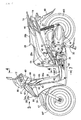
- a body frame F of a scooter-type vehicle includes: a head pipe 13 for steerably supporting a front fork 11 connected to a front wheel WF and a steering handlebar 12 continuous with the upper portion of the front fork 11; and a pair of left and right main frames 14 joined to the head pipe 13 at their front end.
- Each of the main frames 14 integrally includes a down frame portion 14a, a lower frame portion 14b, a rising frame portion 14c and a seat rail portion 14d and is preferably formed by bending a single pipe.
- the down frame portion 14a extends downwardly from the head pipe 13.
- the lower frame portion 14b extends rearwardly from the lower end of the down frame portion 14a and has a rear half portion which is slanted rearwardly upwardly.
- the rising frame portion 14c rises upward from the rear end of the lower frame portion 14b.
- the seat rail portion 14d extends rearwardly while being slanted rearwardly upwardly from the upper end of the rising frame portion 14c.
- the body frame F further includes a cross member 15, a front sub-frame 16, a pair of left and right step frames 17, a pair of left and right rear sub-frames 18 and a pair of left and right pivot plates 19, in addition to the head pipe 13 and both the main frames 14.
- the cross member 15 is provided between respective front portions of the lower frame portions 14b of the main frames 14.
- the front sub-frame 16 is provided between the head pipe 13 and a widthwise central portion of the cross member 15, and is disposed rearwardly of the down frame portions 14a of the main frames 14.
- Both the step frames 17 are disposed above the corresponding lower frame portions 14b.
- the step frames 17 are joined at front ends to the corresponding lower portions of the down frame portions 14a of the main frames 14, extend rearwardly, and joined at their rear ends to the corresponding rear portions of the lower frame portions 14b In this way, the lower frame portions 14b of the main frames 14 and the step frames 17 constitute a low floor portion 20 located rearwardly of the head pipe 13.
- the rear sub-frames 18 are each provided between a rear portion of the lower frame portion 14b of the main frame 14 and a front portion of the seat rail portion 14d, so as to be located below the lower frame portion 14b of the main frame 14 and rearwardly of the rising frame portion 14c.
- the pivot plates 19 are each provided between the rear portion of the lower frame portion 14b of the main frame 14 and the lower portion of the rising frame portion 14c, and the lower portion of the rear sub-frame 18.
- a power unit P composed of an engine E and a transmission device M is supported by the pivot plates 19 so that it can swing up and down.
- the engine E is disposed forwardly of a rear wheel WR.
- the transmission device M is configured to transmit output power of the engine E toward the rear wheel WR while changing the output power and is disposed on the left side of the rear wheel WR.
- the rear wheel WR is rotatably supported by the rear portion of the power unit P.
- a rear cushion unit 23 is disposed between a rear portion of the left seat rail portion 14d of the body frame F and the rear portion of the power unit P.
- An air cleaner 25 disposed at an upstream end of an intake system 24 provided for the engine E is disposed on and supported by the power unit P.
- a storage box 26 is disposed above the engine E so as to be supported between the front portions of the seat rail portions 14d.
- a fuel tank 27 is disposed rearwardly of the storage box 26 so as to be supported between the rear portions of the seat rail portions 14d.
- a riding seat 28 is formed as a tandem-type by integrally including a rider seat portion 28a and a pillion passenger seat portion 28b disposed rearwardly of the rider seat portion 28a.
- the low floor portion 20 of the body frame F is located between the head pipe 13 and the riding seat 28.
- the riding seat 28 is disposed to cover the storage box 26 and the fuel tank 27 from above.
- the front end portion of the riding seat 28 is rotatably connected to the front end upper portion of the storage box 26.
- a battery (not shown) is housed in the low floor portion 20 of the body frame F.
- a side stand 29 is rotatably attached to a front portion of the left pivot plate 19, and a main stand 30 is rotatably attached to a lower portion of the power unit P.
- Support pipes 31 are secured to intermediate portions of both the rear sub-frames 18 so as to extend rearwardly upwardly.
- Pillion passenger steps 33 on which a pillion passenger sitting on the pillion passenger seat portion 28b can rest their feet, are supported by respective step support portions 32 which are provided at the corresponding rear portion of the support pipes 31.
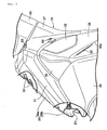
- the body cover 35 includes an upper front cover 36 covering the head pipe 13 from the front; a centre cowl 37 covering from the rear side the upper portion of the down frame portion 14a of the main frame 14 and the head pipe 13 and merging with the rear portion of the upper front cover 36; a leg shield 38 provided continuously with the centre cowl 37 so as to cover from the front both the feet of the rider sitting on the rider seat portion 28a of the riding seat 28; and a lower front cover 39 disposed rearwardly of the front wheel WF so as to connect between blinkers 51 installed on both sides of the leg shield 38 and on both sides of the upper front cover 36.
- the body cover 35 further includes a floor cover 43 continuous with the lower portion of the leg shield 38 and of the lower front cover 39 so as to cover the low floor portion 20 of the body frame F from above and both sides; seat side covers 44 each covering from the side a rear portion of the body frame F, i.e., the rising frame portion 14c and seat rail portion 14d of the main frame 14 and the rear sub-frame 18 below the riding seat 28; seat lower covers 45 each disposed between the floor cover 43 and the seat side cover 44 as viewed from the side; and rear side covers 46 continuous with the rear portion of the seat side cover 44.
- the centre cowl 37 is formed in a shape whose widthwise central portion projects downward.
- the leg shield 38 is formed with vertically extending ridge lines 38a, 38a on both sides.
- the leg shield 38 is formed at a widthwise central portion with a recessed portion 81 conforming to the projecting portion of the centre cowl 37.
- the front wheel WF is covered from above by a front fender 47 supported by the front fork 11.
- the rear wheel WR is covered from the rear and from above by a rear fender 48 disposed to project downwardly from the rear portions of the rear side covers 46.
- a central portion of the steering handlebar 12 is covered by a handlebar cover 49.
- a headlight 50 is disposed at the front portion of the handlebar cover 49.
- the blinkers 51 are disposed on the left and right sides of the upper front cover 36.
- both the left and right side upper portions of the lower front cover 39, the blinkers 51 on both sides of the upper front cover 36, and both the left and right upper portions of the leg shield 38 are connected together at the front portion of the body cover 35 with corresponding front side covers 40 located at respective most outward positions.
- the front side covers 40 which constitute part of the body cover 35, are formed separately from the lower front cover 39, the upper front cover 36 and the leg shield 38. In this way, if a portion of the front portion of the body cover 35 located at the most outward position is damaged, it is possible to deal with such an event by replacing only the front side cover 40.
- a meter unit 53 including a speed meter and a fuel meter is disposed on the upper portion of the handlebar cover 49.
- a dimmer switch 54, a horn switch 55 and a blinker switch 56 are disposed at the left end portion of the handlebar cover 49.
- a kill switch 57 and a starter switch 58 are disposed at the right end of the handlebar cover 49.
- An antilock brake controller 59 and a horn 60 are disposed in front of the head pipe 13, the horn 60 being located above the antilock brake controller 59.
- the antilock brake controller 59 and the horn 60 are housed between the upper front cover 36 and the centre cowl 37.
- the upper front cover 36 is composed of an upper front cover upper part 36a shaped to project downwardly in a lower edge centre and an upper front cover lower part 36b shaped to sag downwardly in an upper edge centre.
- a lower suction hole 61 is formed between the front end lower portion of the upper front cover lower part 36b and the upper end upper portion of the lower front cover 39 to introduce running air into between the upper front cover 36 and the centre cowl 37.
- a plurality of upper suction holes 62 are formed at the front portion of the upper front cover upper part 36a of the upper front cover 36 and in front of the horn 60 so as to introduce running air into between the upper front cover 36 and the centre cowl 37.
- a plurality of first lead-out holes 63 are formed at both side upper ends of the centre cowl 37 so as to lead out the air introduced into between the upper front cover 36 and the centre cowl 37.
- the leg shield 38 is formed with elongate second lead-out holes 82, 82 slanted inwardly along the corresponding ridge lines 38a, 38a of the leg shield 38. In this way, it is possible to arrange air flow in the space surrounded by the upper front cover 36 and centre cowl 37.
- the leg shield 38 is integrally provided at a left upper portion with a cylindrical change box 64 whose front end is closed.
- a lid 65 closing the rear end opening portion of the change box 64 is rotatably attached to the leg shield 38.
- the leg shield 38 is provided with an insertion hole 66 below the change box 64.
- An arm portion 65a provided integrally, i.e., continuously with the lower portion of the lid 65 is inserted into the leg shield 38 from the insertion hole 66.
- a pair of brackets 67 is provided integrally with the front surface of the leg shield 38.
- the arm portion 65a is supported by the brackets 67 and can rotate around a pin 68. In this way, the lid 65 can be moved between a position where the rear end opening portion of the change box 64 is closed (as illustrated in Fig. 6 ) and a position where the arm portion 65a is turned to a position coming into contact with the leg shield 38 at the lower lateral edge of the opening portion to open the rear end opening portion of the change box 64.
- the leg shield 38 is integrally formed with an engaging piece 69 above the rear end opening portion of the change box 64.
- the engaging piece 69 is engaged with an upper end portion of the lid 65 when the lid is in the closed position, to hold the lid 65 in the closed position.
- the engaging piece 69 can be turned to a position releasing the engagement with the lid 65.
- a key cylinder 83 is disposed at a right upper end portion of the leg shield 38.
- a maintenance cover 84 is attached to a right lower portion of the leg shield 38 in an openable and closable manner. The maintenance cover 84 is used to access a feed water inlet to a radiator 85 (see Fig.1 ) disposed between the down frame portions 14a of the pair of left and right main frames 14.
- the floor cover 43 is composed of a step floor cover 41 and a pair of side floor covers 42.
- the step floor cover 41 allows the feet of the rider sitting on the rider seat portion 28a of the riding seat 28 to rest thereon and covers the low floor portion 20 of the body frame F from above.
- the pair of side floor covers 42 are formed separately from the step floor cover 41, are provided continuously with both left and right sides of the step floor cover 41, and cover the low floor portion 20 from the side.
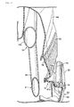
- the pillion passenger steps 33 which the pillion passenger sitting on the pillion passenger seat portion 18b can rest their feet on, are each rotatably supported by the step support portion 32 via a support shaft 74 with an axis tilted forwardly upwardly.
- the pillion passenger steps 33 are supported by the body frame F so as to be movable between an extended position where they project from each of both the left and right rear portion of the floor cover 43 included in the body cover 35, and a stored position (the position illustrated in Figs. 8 and 9 ) where they are folded toward the floor cover 43.
- each recessed storage portion 70 is composed of a rear portion of the side floor cover 42 and a rearwardly extending portion 41 a provided continuously with each of both left and right rear portions of the step floor cover 41 so as to be located above the rear portion of the side floor cover 42.
- the rearwardly extending portion 41 a is supported by a support plate 71 secured to the support pipe 31 provided on the body frame F by means of a weld nut 72 and a bolt 73.
- the pillion passenger steps 33 are each provided with a flat foot-resting surface 33a for receiving the foot of the pillion passenger resting thereon. Since the support shaft 74 has an axis tilted forwardly upwardly, the foot-resting surface 33a will also be tilted forwardly upwardly in the extended position of the pillion passenger step 33.
- a part of the rearwardly extending portion 41 a of the step floor cover 41 forms an inner-end closing portion of the recessed storage portion 70.
- a step-opposing wall portion 75 forming the inner-end closing portion is formed in the rearwardly extending portion 41 a so as to be opposed to the foot-resting surface 33a of the pillion passenger step 33 when the step 33 is in the stored position.
- the seat lower covers 45 are each formed separately from the step floor cover 41 and side floor cover 42 of the floor cover 43 and from the seat side cover 44.
- the seat lower cover 45 is disposed between the floor cover 43 and the seat side cover 44 as viewed from the side so as to be tilted rearwardly upwardly along the upper edge of the recessed storage portion 70.
- the seat lower cover 45 is formed to extend to the front of the pillion passenger step 33 as stored in the recessed storage portion 70. Thus, the seat lower cover 45 can cover a portion likely to contact a tiptoe or the like.
- Figs. 2 and 8 illustrate the different tone by stippling the surface of the seat lower cover 45.
- a lower portion of each of the seat side covers 44 and an upper portion of each of the seat lower covers 45 are formed inwardly concavely so as to cooperatively form a curved recessed portion 76.
- Fig. 8 depicts, with a chain line, a straight line connecting an external surface of a vertical intermediate portion of the seat side cover 44 with an external surface of a lower portion of the seat lower cover 45.
- the curved recessed portion 76 is formed inwardly concavely from the chain line.
- the curved recessed portion 76 is formed to be tilted rearward upwardly.
- a grab rail carrier 78 partially overlapping the rear portion of the pillion passenger seat portion 28b of the riding seat 28 as viewed from the side is disposed above the rear wheel WR.
- a taillight 79 is disposed between the rear wheel WR and the grab rail carrier 78 in the vertical direction.
- the rear side covers 46 constituting part of the body cover 35 are each formed separately from a corresponding one of the seat side covers 44.
- the rear side covers 46 are each disposed below the grab rail carrier 78 as viewed from the side and between the seat side cover 44 and the taillight 79 in the front-to-back direction.
- the rear side covers 46 are each formed in a substantially V-shape, which opens rearwardly, and the taillight 79 is partially disposed in a valley portion of the V-shape.
- Fig. 2 illustrates the different tone by stippling the surface of the rear side cover 46.
- the pillion passenger steps 33 are each supported by the body frame F to be operable between the extended position where it projects from the body cover 35 so as to be able to receive the feet, resting thereon, of the pillion passenger sitting on the pillion passenger seat portion 28b, and the stored position where it is folded toward the body cover 35.
- the floor cover 43 constituting part of the body cover 35 so as to cover the low floor portion 20 included in the body frame F from above and both sides is provided with the recessed storage portions 70, each storing a pillion passenger step 33 in its stored position.
- the seat lower covers 45 each formed separately from the seat side cover 44 and the floor cover 43 covering, from the side, the rear portion of the body frame F below the riding seat 28 while constituting part of the body cover 35 are each disposed between the floor cover 43 and the seat side cover 44 as viewed from the side. Therefore, if the seat lower covers 45 are scratched during the use of the pillion passenger steps 33, only the relatively small-sized (and correspondingly relatively cheap) seat lower cover 45 needs to be replaced. Thus, a replacement part can be replaced with ease at low cost.
- the seat lower covers 45 are each tilted rearwardly upwardly along the upper edge of the recessed storage portion 70. Therefore, when the pillion passenger sitting on the pillion passenger seat portion 28b extends her or his legs from the rear upside toward the front downside and rests his or her feet on the pillion passenger steps 33, the seat lower cover 45 is shaped to match with the movement of the leg, so that the portion which is more likely to be damaged can effectively be made as a separate member. Thus, the seat lower cover 45 can be further reduced in size.
- the pillion passenger steps 33 are each provided with the foot-resting surface 33a used to receive the foot of the pillion passenger resting thereon.
- a contact area of the foot with the pillion passenger step 33 can largely be ensured to improve a sense of safety.
- the feet of the pillion passenger sitting on the pillion passenger seat portion 28b point forwardly and upwardly.
- the foot-resting surface 33a is tilted forwardly upwardly; therefore, the pillion passenger can rest his or her feet on the pillion passenger steps 33 without a sense of discomfort.
- the seat lower covers 45 are each coloured differently in tone from the floor cover 43 and the seat side cover 44; therefore, emphasis in view of design can be placed. In addition, a colour occupation area of each of the seat side covers 44 is reduced on the side surface of the vehicle, which can make the vehicle look compact.
- each of the seat side covers 44 and the upper portion of each of the seat lower covers 45 are formed inwardly concavely to cooperatively form the curved recessed portion 76. Therefore, running-air flowing along the side surface of the vehicle body can be arranged. In addition, since the curved recessed portions 76 are each tilted rearwardly upwardly, the running-air flowing along the side surface of the vehicle body can be arranged effectively.
- the floor cover 43 is composed of the step floor cover 41 which covers the low floor portion 20 from above in such a manner that the rider sitting on the rider seat portion 28a rests the feet thereon; and the pair of side floor covers 42 formed separately from the step floor cover 41, provided continuously with both the left and right sides of the step floor cover 41, and covering the low floor portion 20 from the side.
- the step floor cover 41 is formed with the step-opposing wall portions 75 each constituting the inner-end closing portion of each of the recessed storage portions 70 so as to face the pillion passenger step 33 when it is located in its stored position. Therefore, the number of component parts can be reduced.
- a portion of the step floor on which a foot rests is likely to be scratched with gravel and the like adhering to the foot of the rider; therefore, it cannot be painted.
- the inner-end closing portion of each of the storing recessed portions 70 is likely to be scratched by contact with the side surface of the pillion passenger's foot resting on the pillion passenger step 33 when it is in its extended position; therefore, it cannot be painted.
- the portion incapable of being painted is continuously formed as the step floor cover 41 which is a single part, so that the number of component parts can be reduced.
- the grab rail carrier 78 is disposed above the rear wheel WR so as to partially overlap the rear portion of the pillion passenger seat portion 28b as viewed from the side.
- the taillight 79 is disposed between the rear wheel WR and the grab rail carrier 78 in the vertical direction.
- the rear side covers 46 separate from the seat side covers 44 are each disposed below the grab rail carrier 78 as viewed from the side and between the seat side cover 44 and the taillight 79 in the front-to-back direction.
- the seat side cover 44 and the rear side cover 46 are coloured differently in tone from each other; therefore, emphasis in view of design can be placed.
- a colour occupation area of each of the seat side covers 44 is reduced on the side surface of the vehicle, which can make the vehicle look compact.
Landscapes
- Engineering & Computer Science (AREA)
- Mechanical Engineering (AREA)
- Automatic Cycles, And Cycles In General (AREA)
Applications Claiming Priority (1)
| Application Number | Priority Date | Filing Date | Title |
|---|---|---|---|
| JP2009265987A JP5254186B2 (ja) | 2009-11-24 | 2009-11-24 | スクータ型車両 |
Publications (3)
| Publication Number | Publication Date |
|---|---|
| EP2327615A2 true EP2327615A2 (de) | 2011-06-01 |
| EP2327615A3 EP2327615A3 (de) | 2012-11-28 |
| EP2327615B1 EP2327615B1 (de) | 2015-02-18 |
Family
ID=43533135
Family Applications (1)
| Application Number | Title | Priority Date | Filing Date |
|---|---|---|---|
| EP10251941.0A Active EP2327615B1 (de) | 2009-11-24 | 2010-11-17 | Motorrollerartiges Fahrzeug |
Country Status (3)
| Country | Link |
|---|---|
| EP (1) | EP2327615B1 (de) |
| JP (1) | JP5254186B2 (de) |
| CN (1) | CN102069873B (de) |
Cited By (4)
| Publication number | Priority date | Publication date | Assignee | Title |
|---|---|---|---|---|
| EP2669158A1 (de) * | 2012-05-28 | 2013-12-04 | Yamaha Hatsudoki Kabushiki Kaisha | Grätschsitz-Fahrzeug |
| EP3012178A1 (de) * | 2014-10-24 | 2016-04-27 | Yamaha Hatsudoki Kabushiki Kaisha | Grätschsitz-fahrzeug |
| WO2019092745A1 (en) * | 2017-11-09 | 2019-05-16 | Hero MotoCorp Limited | Floor of a two wheeled vehicle |
| EP3357803B1 (de) * | 2015-09-28 | 2021-11-24 | Honda Motor Co., Ltd. | Sattelfahrzeug |
Families Citing this family (11)
| Publication number | Priority date | Publication date | Assignee | Title |
|---|---|---|---|---|
| CN103963884B (zh) * | 2013-01-30 | 2018-04-20 | 雅马哈发动机株式会社 | 跨坐型车辆 |
| JP5736015B2 (ja) * | 2013-08-30 | 2015-06-17 | 本田技研工業株式会社 | ボディカバー構造 |
| JP2016008020A (ja) * | 2014-06-26 | 2016-01-18 | ヤマハ発動機株式会社 | 車両 |
| JP5993902B2 (ja) * | 2014-07-18 | 2016-09-14 | 本田技研工業株式会社 | スクータ型車両の排気装置 |
| JP5932920B2 (ja) * | 2014-08-29 | 2016-06-08 | 本田技研工業株式会社 | 自動二輪車用車体カバーの前部構造 |
| CN105818897B (zh) * | 2015-01-09 | 2018-06-15 | 雅马哈发动机株式会社 | 速克达型车辆 |
| JP6656425B2 (ja) * | 2016-05-30 | 2020-03-04 | 本田技研工業株式会社 | 自動二輪車ステップ周辺のカバー構造 |
| CN106064651A (zh) * | 2016-07-06 | 2016-11-02 | 罗瑞运动用品(昆山)有限公司 | 一种折叠式脚踏 |
| CN108688754B (zh) * | 2017-03-31 | 2021-07-09 | Tvs电机股份有限公司 | 一种跨步式车辆 |
| CN109204651B (zh) * | 2017-06-29 | 2022-04-08 | Tvs电机股份有限公司 | 一种骑跨式车辆 |
| JP7177757B2 (ja) * | 2019-08-27 | 2022-11-24 | 本田技研工業株式会社 | 鞍乗り型車両のステップ構造 |
Citations (1)
| Publication number | Priority date | Publication date | Assignee | Title |
|---|---|---|---|---|
| JP3938652B2 (ja) | 2000-07-05 | 2007-06-27 | ヤマハ発動機株式会社 | スクータ型車両の外装構造 |
Family Cites Families (11)
| Publication number | Priority date | Publication date | Assignee | Title |
|---|---|---|---|---|
| JPS6017428Y2 (ja) * | 1982-09-20 | 1985-05-28 | 本田技研工業株式会社 | 自動二輪車等のピリオンステツプ装置 |
| JPH0858657A (ja) * | 1994-08-26 | 1996-03-05 | Suzuki Motor Corp | 二人乗りスクータ型車輛のフレームカバー |
| US6588529B2 (en) * | 2000-07-05 | 2003-07-08 | Yamaha Hatsudoki Kabishuki Kaisha | Body cover and structure for motorcycle |
| JP2002173071A (ja) * | 2000-12-05 | 2002-06-18 | Honda Motor Co Ltd | ピリオンステップ構造 |
| JP3847087B2 (ja) * | 2000-12-05 | 2006-11-15 | 本田技研工業株式会社 | スクータ型車両の車体カバー構造 |
| JP4108287B2 (ja) * | 2001-03-28 | 2008-06-25 | 本田技研工業株式会社 | 自動二輪車のピリオンステップホルダ構造 |
| JP3842118B2 (ja) * | 2001-12-04 | 2006-11-08 | 本田技研工業株式会社 | 車両の車体構造 |
| CN100519316C (zh) * | 2003-12-31 | 2009-07-29 | 雅马哈发动机株式会社 | 机动二轮车之方向灯/尾灯的组合构造 |
| CN2871356Y (zh) * | 2005-12-22 | 2007-02-21 | 光阳工业股份有限公司 | 摩托车 |
| ES2331744T3 (es) * | 2006-08-09 | 2010-01-14 | Kwang Yang Motor Co., Ltd. | Mecanismo de reposapies para una motocicleta de tipo scooter. |
| JP5091731B2 (ja) * | 2008-03-14 | 2012-12-05 | 本田技研工業株式会社 | 自動二輪車のリヤサイドカバー支持構造 |
-
2009
- 2009-11-24 JP JP2009265987A patent/JP5254186B2/ja not_active Expired - Fee Related
-
2010
- 2010-11-16 CN CN2010105516973A patent/CN102069873B/zh active Active
- 2010-11-17 EP EP10251941.0A patent/EP2327615B1/de active Active
Patent Citations (1)
| Publication number | Priority date | Publication date | Assignee | Title |
|---|---|---|---|---|
| JP3938652B2 (ja) | 2000-07-05 | 2007-06-27 | ヤマハ発動機株式会社 | スクータ型車両の外装構造 |
Cited By (7)
| Publication number | Priority date | Publication date | Assignee | Title |
|---|---|---|---|---|
| EP2669158A1 (de) * | 2012-05-28 | 2013-12-04 | Yamaha Hatsudoki Kabushiki Kaisha | Grätschsitz-Fahrzeug |
| TWI465361B (zh) * | 2012-05-28 | 2014-12-21 | Yamaha Motor Co Ltd | 跨坐型車輛 |
| EP3012178A1 (de) * | 2014-10-24 | 2016-04-27 | Yamaha Hatsudoki Kabushiki Kaisha | Grätschsitz-fahrzeug |
| CN105584570A (zh) * | 2014-10-24 | 2016-05-18 | 雅马哈发动机株式会社 | 跨坐型车辆 |
| CN105584570B (zh) * | 2014-10-24 | 2018-04-06 | 雅马哈发动机株式会社 | 跨坐型车辆 |
| EP3357803B1 (de) * | 2015-09-28 | 2021-11-24 | Honda Motor Co., Ltd. | Sattelfahrzeug |
| WO2019092745A1 (en) * | 2017-11-09 | 2019-05-16 | Hero MotoCorp Limited | Floor of a two wheeled vehicle |
Also Published As
| Publication number | Publication date |
|---|---|
| EP2327615A3 (de) | 2012-11-28 |
| CN102069873A (zh) | 2011-05-25 |
| EP2327615B1 (de) | 2015-02-18 |
| JP5254186B2 (ja) | 2013-08-07 |
| CN102069873B (zh) | 2013-06-05 |
| JP2011110946A (ja) | 2011-06-09 |
Similar Documents
| Publication | Publication Date | Title |
|---|---|---|
| EP2327615B1 (de) | Motorrollerartiges Fahrzeug | |
| US9765731B2 (en) | Canister arrangement structure for saddle-ride type vehicle | |
| JP5246431B2 (ja) | 自動二輪車 | |
| EP1524177B1 (de) | Fernbedienungseinrichtung für motorrollerartiges Fahrzeug | |
| JP5926653B2 (ja) | 鞍乗り型車両の収納部構造 | |
| EP2463184B1 (de) | Motorrad | |
| JP2005112313A (ja) | スクータ型車両の物品収納構造 | |
| JP4119344B2 (ja) | 自動二輪車 | |
| JP2005112312A (ja) | 自動二輪車 | |
| US20090108557A1 (en) | Motorcycle | |
| TW201637920A (zh) | 跨坐型車輛之收納部構造 | |
| EP1783040A1 (de) | Im Grätschsitz zu benutzendes Fahrzeug | |
| JP4377954B1 (ja) | 鞍乗型車両 | |
| JP4567083B2 (ja) | 鞍乗型車両 | |
| JP2016135655A (ja) | 鞍乗り型車両 | |
| TWI360496B (de) | ||
| EP1524178A2 (de) | Fernbedienungsgerät für ein leichtes Fahrzeug | |
| JP4478195B1 (ja) | 自動二輪車 | |
| JP2009173216A (ja) | 鞍乗り型車両のシート構造 | |
| JP5133541B2 (ja) | 鞍乗型車両 | |
| JP4825908B2 (ja) | 鞍乗型車両 | |
| JP2010149796A (ja) | 鞍乗型車両 | |
| JP2009173218A (ja) | 鞍乗り型車両のレッグシールド構造及び鞍乗り型車両 | |
| JP2005112309A (ja) | スクータ型車両 | |
| CN104210590B (zh) | 摩托车 |
Legal Events
| Date | Code | Title | Description |
|---|---|---|---|
| PUAI | Public reference made under article 153(3) epc to a published international application that has entered the european phase |
Free format text: ORIGINAL CODE: 0009012 |
|
| AK | Designated contracting states |
Kind code of ref document: A2 Designated state(s): AL AT BE BG CH CY CZ DE DK EE ES FI FR GB GR HR HU IE IS IT LI LT LU LV MC MK MT NL NO PL PT RO RS SE SI SK SM TR |
|
| AX | Request for extension of the european patent |
Extension state: BA ME |
|
| PUAL | Search report despatched |
Free format text: ORIGINAL CODE: 0009013 |
|
| AK | Designated contracting states |
Kind code of ref document: A3 Designated state(s): AL AT BE BG CH CY CZ DE DK EE ES FI FR GB GR HR HU IE IS IT LI LT LU LV MC MK MT NL NO PL PT RO RS SE SI SK SM TR |
|
| AX | Request for extension of the european patent |
Extension state: BA ME |
|
| RIC1 | Information provided on ipc code assigned before grant |
Ipc: B62J 17/00 20060101AFI20121019BHEP Ipc: B62J 25/00 20060101ALI20121019BHEP |
|
| 17P | Request for examination filed |
Effective date: 20130520 |
|
| 17Q | First examination report despatched |
Effective date: 20140304 |
|
| GRAP | Despatch of communication of intention to grant a patent |
Free format text: ORIGINAL CODE: EPIDOSNIGR1 |
|
| INTG | Intention to grant announced |
Effective date: 20140821 |
|
| GRAS | Grant fee paid |
Free format text: ORIGINAL CODE: EPIDOSNIGR3 |
|
| GRAA | (expected) grant |
Free format text: ORIGINAL CODE: 0009210 |
|
| AK | Designated contracting states |
Kind code of ref document: B1 Designated state(s): AL AT BE BG CH CY CZ DE DK EE ES FI FR GB GR HR HU IE IS IT LI LT LU LV MC MK MT NL NO PL PT RO RS SE SI SK SM TR |
|
| REG | Reference to a national code |
Ref country code: GB Ref legal event code: FG4D |
|
| REG | Reference to a national code |
Ref country code: CH Ref legal event code: EP |
|
| REG | Reference to a national code |
Ref country code: AT Ref legal event code: REF Ref document number: 710531 Country of ref document: AT Kind code of ref document: T Effective date: 20150315 |
|
| REG | Reference to a national code |
Ref country code: IE Ref legal event code: FG4D |
|
| REG | Reference to a national code |
Ref country code: DE Ref legal event code: R096 Ref document number: 602010022304 Country of ref document: DE Effective date: 20150402 |
|
| REG | Reference to a national code |
Ref country code: NL Ref legal event code: VDEP Effective date: 20150218 |
|
| REG | Reference to a national code |
Ref country code: AT Ref legal event code: MK05 Ref document number: 710531 Country of ref document: AT Kind code of ref document: T Effective date: 20150218 |
|
| REG | Reference to a national code |
Ref country code: LT Ref legal event code: MG4D |
|
| PG25 | Lapsed in a contracting state [announced via postgrant information from national office to epo] |
Ref country code: FI Free format text: LAPSE BECAUSE OF FAILURE TO SUBMIT A TRANSLATION OF THE DESCRIPTION OR TO PAY THE FEE WITHIN THE PRESCRIBED TIME-LIMIT Effective date: 20150218 Ref country code: LT Free format text: LAPSE BECAUSE OF FAILURE TO SUBMIT A TRANSLATION OF THE DESCRIPTION OR TO PAY THE FEE WITHIN THE PRESCRIBED TIME-LIMIT Effective date: 20150218 Ref country code: ES Free format text: LAPSE BECAUSE OF FAILURE TO SUBMIT A TRANSLATION OF THE DESCRIPTION OR TO PAY THE FEE WITHIN THE PRESCRIBED TIME-LIMIT Effective date: 20150218 Ref country code: HR Free format text: LAPSE BECAUSE OF FAILURE TO SUBMIT A TRANSLATION OF THE DESCRIPTION OR TO PAY THE FEE WITHIN THE PRESCRIBED TIME-LIMIT Effective date: 20150218 Ref country code: NO Free format text: LAPSE BECAUSE OF FAILURE TO SUBMIT A TRANSLATION OF THE DESCRIPTION OR TO PAY THE FEE WITHIN THE PRESCRIBED TIME-LIMIT Effective date: 20150518 Ref country code: SE Free format text: LAPSE BECAUSE OF FAILURE TO SUBMIT A TRANSLATION OF THE DESCRIPTION OR TO PAY THE FEE WITHIN THE PRESCRIBED TIME-LIMIT Effective date: 20150218 |
|
| PG25 | Lapsed in a contracting state [announced via postgrant information from national office to epo] |
Ref country code: RS Free format text: LAPSE BECAUSE OF FAILURE TO SUBMIT A TRANSLATION OF THE DESCRIPTION OR TO PAY THE FEE WITHIN THE PRESCRIBED TIME-LIMIT Effective date: 20150218 Ref country code: LV Free format text: LAPSE BECAUSE OF FAILURE TO SUBMIT A TRANSLATION OF THE DESCRIPTION OR TO PAY THE FEE WITHIN THE PRESCRIBED TIME-LIMIT Effective date: 20150218 Ref country code: IS Free format text: LAPSE BECAUSE OF FAILURE TO SUBMIT A TRANSLATION OF THE DESCRIPTION OR TO PAY THE FEE WITHIN THE PRESCRIBED TIME-LIMIT Effective date: 20150618 Ref country code: GR Free format text: LAPSE BECAUSE OF FAILURE TO SUBMIT A TRANSLATION OF THE DESCRIPTION OR TO PAY THE FEE WITHIN THE PRESCRIBED TIME-LIMIT Effective date: 20150519 Ref country code: AT Free format text: LAPSE BECAUSE OF FAILURE TO SUBMIT A TRANSLATION OF THE DESCRIPTION OR TO PAY THE FEE WITHIN THE PRESCRIBED TIME-LIMIT Effective date: 20150218 Ref country code: NL Free format text: LAPSE BECAUSE OF FAILURE TO SUBMIT A TRANSLATION OF THE DESCRIPTION OR TO PAY THE FEE WITHIN THE PRESCRIBED TIME-LIMIT Effective date: 20150218 |
|
| REG | Reference to a national code |
Ref country code: FR Ref legal event code: PLFP Year of fee payment: 6 |
|
| PG25 | Lapsed in a contracting state [announced via postgrant information from national office to epo] |
Ref country code: SK Free format text: LAPSE BECAUSE OF FAILURE TO SUBMIT A TRANSLATION OF THE DESCRIPTION OR TO PAY THE FEE WITHIN THE PRESCRIBED TIME-LIMIT Effective date: 20150218 Ref country code: CZ Free format text: LAPSE BECAUSE OF FAILURE TO SUBMIT A TRANSLATION OF THE DESCRIPTION OR TO PAY THE FEE WITHIN THE PRESCRIBED TIME-LIMIT Effective date: 20150218 Ref country code: EE Free format text: LAPSE BECAUSE OF FAILURE TO SUBMIT A TRANSLATION OF THE DESCRIPTION OR TO PAY THE FEE WITHIN THE PRESCRIBED TIME-LIMIT Effective date: 20150218 Ref country code: RO Free format text: LAPSE BECAUSE OF FAILURE TO SUBMIT A TRANSLATION OF THE DESCRIPTION OR TO PAY THE FEE WITHIN THE PRESCRIBED TIME-LIMIT Effective date: 20150218 Ref country code: DK Free format text: LAPSE BECAUSE OF FAILURE TO SUBMIT A TRANSLATION OF THE DESCRIPTION OR TO PAY THE FEE WITHIN THE PRESCRIBED TIME-LIMIT Effective date: 20150218 |
|
| REG | Reference to a national code |
Ref country code: DE Ref legal event code: R097 Ref document number: 602010022304 Country of ref document: DE |
|
| PG25 | Lapsed in a contracting state [announced via postgrant information from national office to epo] |
Ref country code: PL Free format text: LAPSE BECAUSE OF FAILURE TO SUBMIT A TRANSLATION OF THE DESCRIPTION OR TO PAY THE FEE WITHIN THE PRESCRIBED TIME-LIMIT Effective date: 20150218 |
|
| PLBE | No opposition filed within time limit |
Free format text: ORIGINAL CODE: 0009261 |
|
| STAA | Information on the status of an ep patent application or granted ep patent |
Free format text: STATUS: NO OPPOSITION FILED WITHIN TIME LIMIT |
|
| 26N | No opposition filed |
Effective date: 20151119 |
|
| PG25 | Lapsed in a contracting state [announced via postgrant information from national office to epo] |
Ref country code: SI Free format text: LAPSE BECAUSE OF FAILURE TO SUBMIT A TRANSLATION OF THE DESCRIPTION OR TO PAY THE FEE WITHIN THE PRESCRIBED TIME-LIMIT Effective date: 20150218 |
|
| PG25 | Lapsed in a contracting state [announced via postgrant information from national office to epo] |
Ref country code: BE Free format text: LAPSE BECAUSE OF FAILURE TO SUBMIT A TRANSLATION OF THE DESCRIPTION OR TO PAY THE FEE WITHIN THE PRESCRIBED TIME-LIMIT Effective date: 20150218 |
|
| PG25 | Lapsed in a contracting state [announced via postgrant information from national office to epo] |
Ref country code: LU Free format text: LAPSE BECAUSE OF FAILURE TO SUBMIT A TRANSLATION OF THE DESCRIPTION OR TO PAY THE FEE WITHIN THE PRESCRIBED TIME-LIMIT Effective date: 20151117 Ref country code: MC Free format text: LAPSE BECAUSE OF FAILURE TO SUBMIT A TRANSLATION OF THE DESCRIPTION OR TO PAY THE FEE WITHIN THE PRESCRIBED TIME-LIMIT Effective date: 20150218 |
|
| REG | Reference to a national code |
Ref country code: CH Ref legal event code: PL |
|
| PG25 | Lapsed in a contracting state [announced via postgrant information from national office to epo] |
Ref country code: LI Free format text: LAPSE BECAUSE OF NON-PAYMENT OF DUE FEES Effective date: 20151130 Ref country code: CH Free format text: LAPSE BECAUSE OF NON-PAYMENT OF DUE FEES Effective date: 20151130 |
|
| REG | Reference to a national code |
Ref country code: IE Ref legal event code: MM4A |
|
| REG | Reference to a national code |
Ref country code: FR Ref legal event code: PLFP Year of fee payment: 7 |
|
| PG25 | Lapsed in a contracting state [announced via postgrant information from national office to epo] |
Ref country code: IE Free format text: LAPSE BECAUSE OF NON-PAYMENT OF DUE FEES Effective date: 20151117 |
|
| PG25 | Lapsed in a contracting state [announced via postgrant information from national office to epo] |
Ref country code: BG Free format text: LAPSE BECAUSE OF FAILURE TO SUBMIT A TRANSLATION OF THE DESCRIPTION OR TO PAY THE FEE WITHIN THE PRESCRIBED TIME-LIMIT Effective date: 20150218 Ref country code: SM Free format text: LAPSE BECAUSE OF FAILURE TO SUBMIT A TRANSLATION OF THE DESCRIPTION OR TO PAY THE FEE WITHIN THE PRESCRIBED TIME-LIMIT Effective date: 20150218 Ref country code: HU Free format text: LAPSE BECAUSE OF FAILURE TO SUBMIT A TRANSLATION OF THE DESCRIPTION OR TO PAY THE FEE WITHIN THE PRESCRIBED TIME-LIMIT; INVALID AB INITIO Effective date: 20101117 |
|
| PG25 | Lapsed in a contracting state [announced via postgrant information from national office to epo] |
Ref country code: CY Free format text: LAPSE BECAUSE OF FAILURE TO SUBMIT A TRANSLATION OF THE DESCRIPTION OR TO PAY THE FEE WITHIN THE PRESCRIBED TIME-LIMIT Effective date: 20150218 |
|
| PG25 | Lapsed in a contracting state [announced via postgrant information from national office to epo] |
Ref country code: MT Free format text: LAPSE BECAUSE OF FAILURE TO SUBMIT A TRANSLATION OF THE DESCRIPTION OR TO PAY THE FEE WITHIN THE PRESCRIBED TIME-LIMIT Effective date: 20150218 Ref country code: TR Free format text: LAPSE BECAUSE OF FAILURE TO SUBMIT A TRANSLATION OF THE DESCRIPTION OR TO PAY THE FEE WITHIN THE PRESCRIBED TIME-LIMIT Effective date: 20150218 |
|
| REG | Reference to a national code |
Ref country code: FR Ref legal event code: PLFP Year of fee payment: 8 |
|
| PG25 | Lapsed in a contracting state [announced via postgrant information from national office to epo] |
Ref country code: MK Free format text: LAPSE BECAUSE OF FAILURE TO SUBMIT A TRANSLATION OF THE DESCRIPTION OR TO PAY THE FEE WITHIN THE PRESCRIBED TIME-LIMIT Effective date: 20150218 Ref country code: PT Free format text: LAPSE BECAUSE OF FAILURE TO SUBMIT A TRANSLATION OF THE DESCRIPTION OR TO PAY THE FEE WITHIN THE PRESCRIBED TIME-LIMIT Effective date: 20150218 |
|
| REG | Reference to a national code |
Ref country code: FR Ref legal event code: PLFP Year of fee payment: 9 |
|
| PG25 | Lapsed in a contracting state [announced via postgrant information from national office to epo] |
Ref country code: AL Free format text: LAPSE BECAUSE OF FAILURE TO SUBMIT A TRANSLATION OF THE DESCRIPTION OR TO PAY THE FEE WITHIN THE PRESCRIBED TIME-LIMIT Effective date: 20150218 |
|
| REG | Reference to a national code |
Ref country code: DE Ref legal event code: R084 Ref document number: 602010022304 Country of ref document: DE |
|
| REG | Reference to a national code |
Ref country code: GB Ref legal event code: 746 Effective date: 20191219 |
|
| PGFP | Annual fee paid to national office [announced via postgrant information from national office to epo] |
Ref country code: DE Payment date: 20191105 Year of fee payment: 10 |
|
| PGFP | Annual fee paid to national office [announced via postgrant information from national office to epo] |
Ref country code: FR Payment date: 20191014 Year of fee payment: 10 |
|
| PGFP | Annual fee paid to national office [announced via postgrant information from national office to epo] |
Ref country code: GB Payment date: 20191115 Year of fee payment: 10 |
|
| REG | Reference to a national code |
Ref country code: DE Ref legal event code: R082 Ref document number: 602010022304 Country of ref document: DE |
|
| REG | Reference to a national code |
Ref country code: DE Ref legal event code: R119 Ref document number: 602010022304 Country of ref document: DE |
|
| GBPC | Gb: european patent ceased through non-payment of renewal fee |
Effective date: 20201117 |
|
| PG25 | Lapsed in a contracting state [announced via postgrant information from national office to epo] |
Ref country code: FR Free format text: LAPSE BECAUSE OF NON-PAYMENT OF DUE FEES Effective date: 20201130 |
|
| PG25 | Lapsed in a contracting state [announced via postgrant information from national office to epo] |
Ref country code: GB Free format text: LAPSE BECAUSE OF NON-PAYMENT OF DUE FEES Effective date: 20201117 Ref country code: DE Free format text: LAPSE BECAUSE OF NON-PAYMENT OF DUE FEES Effective date: 20210601 |
|
| PGFP | Annual fee paid to national office [announced via postgrant information from national office to epo] |
Ref country code: IT Payment date: 20221011 Year of fee payment: 13 |