EP2311527B1 - Tomographie informatisée à faisceau conique avec un imageur à écran plan - Google Patents
Tomographie informatisée à faisceau conique avec un imageur à écran plan Download PDFInfo
- Publication number
- EP2311527B1 EP2311527B1 EP10185747.2A EP10185747A EP2311527B1 EP 2311527 B1 EP2311527 B1 EP 2311527B1 EP 10185747 A EP10185747 A EP 10185747A EP 2311527 B1 EP2311527 B1 EP 2311527B1
- Authority
- EP
- European Patent Office
- Prior art keywords
- computerized tomography
- cone beam
- imager
- radiation therapy
- beam computerized
- Prior art date
- Legal status (The legal status is an assumption and is not a legal conclusion. Google has not performed a legal analysis and makes no representation as to the accuracy of the status listed.)
- Expired - Lifetime
Links
Images


Classifications
-
- A—HUMAN NECESSITIES
- A61—MEDICAL OR VETERINARY SCIENCE; HYGIENE
- A61B—DIAGNOSIS; SURGERY; IDENTIFICATION
- A61B6/00—Apparatus for radiation diagnosis, e.g. combined with radiation therapy equipment
- A61B6/02—Devices for diagnosis sequentially in different planes; Stereoscopic radiation diagnosis
- A61B6/03—Computerised tomographs
- A61B6/032—Transmission computed tomography [CT]
-
- A—HUMAN NECESSITIES
- A61—MEDICAL OR VETERINARY SCIENCE; HYGIENE
- A61B—DIAGNOSIS; SURGERY; IDENTIFICATION
- A61B6/00—Apparatus for radiation diagnosis, e.g. combined with radiation therapy equipment
- A61B6/40—Apparatus for radiation diagnosis, e.g. combined with radiation therapy equipment with arrangements for generating radiation specially adapted for radiation diagnosis
- A61B6/4064—Apparatus for radiation diagnosis, e.g. combined with radiation therapy equipment with arrangements for generating radiation specially adapted for radiation diagnosis specially adapted for producing a particular type of beam
- A61B6/4085—Cone-beams
-
- A—HUMAN NECESSITIES
- A61—MEDICAL OR VETERINARY SCIENCE; HYGIENE
- A61B—DIAGNOSIS; SURGERY; IDENTIFICATION
- A61B6/00—Apparatus for radiation diagnosis, e.g. combined with radiation therapy equipment
- A61B6/46—Apparatus for radiation diagnosis, e.g. combined with radiation therapy equipment with special arrangements for interfacing with the operator or the patient
- A61B6/461—Displaying means of special interest
- A61B6/466—Displaying means of special interest adapted to display 3D data
-
- A—HUMAN NECESSITIES
- A61—MEDICAL OR VETERINARY SCIENCE; HYGIENE
- A61B—DIAGNOSIS; SURGERY; IDENTIFICATION
- A61B6/00—Apparatus for radiation diagnosis, e.g. combined with radiation therapy equipment
- A61B6/50—Clinical applications
- A61B6/508—Clinical applications for non-human patients
-
- A—HUMAN NECESSITIES
- A61—MEDICAL OR VETERINARY SCIENCE; HYGIENE
- A61B—DIAGNOSIS; SURGERY; IDENTIFICATION
- A61B6/00—Apparatus for radiation diagnosis, e.g. combined with radiation therapy equipment
- A61B6/58—Testing, adjusting or calibrating apparatus or devices for radiation diagnosis
- A61B6/582—Calibration
- A61B6/583—Calibration using calibration phantoms
-
- A—HUMAN NECESSITIES
- A61—MEDICAL OR VETERINARY SCIENCE; HYGIENE
- A61N—ELECTROTHERAPY; MAGNETOTHERAPY; RADIATION THERAPY; ULTRASOUND THERAPY
- A61N5/00—Radiation therapy
- A61N5/10—X-ray therapy; Gamma-ray therapy; Particle-irradiation therapy
- A61N5/1048—Monitoring, verifying, controlling systems and methods
- A61N5/1049—Monitoring, verifying, controlling systems and methods for verifying the position of the patient with respect to the radiation beam
-
- A—HUMAN NECESSITIES
- A61—MEDICAL OR VETERINARY SCIENCE; HYGIENE
- A61B—DIAGNOSIS; SURGERY; IDENTIFICATION
- A61B6/00—Apparatus for radiation diagnosis, e.g. combined with radiation therapy equipment
- A61B6/02—Devices for diagnosis sequentially in different planes; Stereoscopic radiation diagnosis
- A61B6/027—Devices for diagnosis sequentially in different planes; Stereoscopic radiation diagnosis characterised by the use of a particular data acquisition trajectory, e.g. helical or spiral
-
- A—HUMAN NECESSITIES
- A61—MEDICAL OR VETERINARY SCIENCE; HYGIENE
- A61B—DIAGNOSIS; SURGERY; IDENTIFICATION
- A61B6/00—Apparatus for radiation diagnosis, e.g. combined with radiation therapy equipment
- A61B6/06—Diaphragms
-
- A—HUMAN NECESSITIES
- A61—MEDICAL OR VETERINARY SCIENCE; HYGIENE
- A61B—DIAGNOSIS; SURGERY; IDENTIFICATION
- A61B6/00—Apparatus for radiation diagnosis, e.g. combined with radiation therapy equipment
- A61B6/44—Constructional features of apparatus for radiation diagnosis
- A61B6/4405—Constructional features of apparatus for radiation diagnosis the apparatus being movable or portable, e.g. handheld or mounted on a trolley
-
- A—HUMAN NECESSITIES
- A61—MEDICAL OR VETERINARY SCIENCE; HYGIENE
- A61B—DIAGNOSIS; SURGERY; IDENTIFICATION
- A61B6/00—Apparatus for radiation diagnosis, e.g. combined with radiation therapy equipment
- A61B6/44—Constructional features of apparatus for radiation diagnosis
- A61B6/4429—Constructional features of apparatus for radiation diagnosis related to the mounting of source units and detector units
- A61B6/4458—Constructional features of apparatus for radiation diagnosis related to the mounting of source units and detector units the source unit or the detector unit being attached to robotic arms
-
- A—HUMAN NECESSITIES
- A61—MEDICAL OR VETERINARY SCIENCE; HYGIENE
- A61B—DIAGNOSIS; SURGERY; IDENTIFICATION
- A61B6/00—Apparatus for radiation diagnosis, e.g. combined with radiation therapy equipment
- A61B6/48—Diagnostic techniques
- A61B6/482—Diagnostic techniques involving multiple energy imaging
-
- A—HUMAN NECESSITIES
- A61—MEDICAL OR VETERINARY SCIENCE; HYGIENE
- A61N—ELECTROTHERAPY; MAGNETOTHERAPY; RADIATION THERAPY; ULTRASOUND THERAPY
- A61N5/00—Radiation therapy
- A61N5/10—X-ray therapy; Gamma-ray therapy; Particle-irradiation therapy
- A61N5/1048—Monitoring, verifying, controlling systems and methods
- A61N5/1049—Monitoring, verifying, controlling systems and methods for verifying the position of the patient with respect to the radiation beam
- A61N2005/1061—Monitoring, verifying, controlling systems and methods for verifying the position of the patient with respect to the radiation beam using an x-ray imaging system having a separate imaging source
-
- A—HUMAN NECESSITIES
- A61—MEDICAL OR VETERINARY SCIENCE; HYGIENE
- A61N—ELECTROTHERAPY; MAGNETOTHERAPY; RADIATION THERAPY; ULTRASOUND THERAPY
- A61N5/00—Radiation therapy
- A61N5/10—X-ray therapy; Gamma-ray therapy; Particle-irradiation therapy
- A61N5/103—Treatment planning systems
- A61N5/1038—Treatment planning systems taking into account previously administered plans applied to the same patient, i.e. adaptive radiotherapy
-
- A—HUMAN NECESSITIES
- A61—MEDICAL OR VETERINARY SCIENCE; HYGIENE
- A61N—ELECTROTHERAPY; MAGNETOTHERAPY; RADIATION THERAPY; ULTRASOUND THERAPY
- A61N5/00—Radiation therapy
- A61N5/10—X-ray therapy; Gamma-ray therapy; Particle-irradiation therapy
- A61N5/1048—Monitoring, verifying, controlling systems and methods
- A61N5/1064—Monitoring, verifying, controlling systems and methods for adjusting radiation treatment in response to monitoring
- A61N5/1065—Beam adjustment
-
- A—HUMAN NECESSITIES
- A61—MEDICAL OR VETERINARY SCIENCE; HYGIENE
- A61N—ELECTROTHERAPY; MAGNETOTHERAPY; RADIATION THERAPY; ULTRASOUND THERAPY
- A61N5/00—Radiation therapy
- A61N5/10—X-ray therapy; Gamma-ray therapy; Particle-irradiation therapy
- A61N5/1048—Monitoring, verifying, controlling systems and methods
- A61N5/1064—Monitoring, verifying, controlling systems and methods for adjusting radiation treatment in response to monitoring
- A61N5/1069—Target adjustment, e.g. moving the patient support
Definitions
- the present invention relates generally to a cone-beam computed tomography process and, more particularly, to a cone-beam computed tomography process that employs an amorphous silicon flat-panel imager for use in radiotherapy applications.
- Radiotherapy involves delivering a prescribed tumorcidal radiation dose to a specific geometrically defined target or target volume. Typically, this treatment is delivered to a patient in one or more therapy sessions (termed fractions). It is not uncommon for a treatment schedule to involve twenty to forty fractions, with five fractions delivered per week. While radiotherapy has proven successful in managing various types and stages of cancer, the potential exists for increased tumor control through increased dose. Unfortunately, delivery of increased dose is limited by the presence of adjacent normal structures and the precision of beam delivery. In some sites, the diseased target is directly adjacent to radiosensitive normal structures.
- the prostate and rectum are directly adjacent.
- the prostate is the targeted volume and the maximum deliverable dose is limited by the wall of the rectum
- a radiation therapy treatment plan is formed based on the location and orientation of the lesion and surrounding structures in an initial computerized tomography or magnetic resonance image.
- the location and orientation of the lesion may vary during the course of treatment from that used to form the radiation therapy treatment plan.
- systematic and/or random variations in patient setup can each change the location and orientation of the lesion at the time of treatment compared to that assumed in the radiation therapy treatment plan.
- the location and orientation of the lesion can vary during a single treatment session (resulting in intrafraction errors) due to normal biological processes, such as breathing, peristalsis, etc.
- Significant dose escalation may be possible if these uncertainties could be reduced from current levels (-I0mm) to 2-3mm.
- a number of techniques have been developed to reduce uncertainty associated with systematic and/or random variations in lesion location resulting from interfraction and intrafraction errors. These include patient immobilization techniques (e. g., masks, body casts, bite blocks, etc.), off-line review processes (e. g., weekly port films, population-based or individual based statistical approaches, repeat computerized tomography scans, etc.), and on-line correction strategies (e. g., pre-ports, MV or kV radiographic or fluoroscopic monitoring, video monitoring, etc.).
- patient immobilization techniques e. g., masks, body casts, bite blocks, etc.
- off-line review processes e. g., weekly port films, population-based or individual based statistical approaches, repeat computerized tomography scans, etc.
- on-line correction strategies e. g., pre-ports, MV or kV radiographic or fluoroscopic monitoring, video monitoring, etc.
- An on-line imaging system providing suitable guidance has several requirements if it is to be applied in radiotherapy of this type. These requirements include contrast sensitivity sufficient to discern soft-tissue ; high spatial resolution and low geometric distortion for precise localization of soft tissue boundaries ; operation within the environment of a radiation treatment machine ; large field-of-view (FOV) capable of imaging patients up to 40cm in diameter; rapid image acquisition (within a few minutes); negligible harm to the patient from the imaging procedure (e. g., dose much less than the treatment dose) ; and compatibility with integration into an external beam radiotherapy treatment machine.
- FOV field-of-view
- Acquiring computerized tomography images at the time of treatment is possible, for example, by incorporating a computerized tomography scanner into the radiation therapy environment (e. g., with the treatment table translated between the computerized tomography scanner gantry and the radiation therapy gantry along rails) or by modifying the treatment machine to allow computerized tomography scanning.
- the former approach is a fairly expensive solution, requiring the installation of a dedicated computerized tomography scanner in the treatment room.
- the latter approach is possible, for example, by modifying a computer tomography scanner gantry to include mechanisms for radiation treatment delivery, as in systems for tomotherapy.
- soft-tissue visualization of the target volume can in some instances be accomplished by means of an ultrasound imaging system attached in a well-defined geometry to the radiation therapy machine.
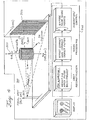
- a typical radiation therapy system 100 incorporates a 4-25 MV medical linear accelerator 102, a collimator 104 for collimating and shaping the radiation field 106 that is directed onto a patient 108 who is supported on a treatment table 110 in a given treatment position.
- Treatment involves irradiation of a lesion 112 located within a target volume with a radiation beam 114 directed at the lesion from one or more angles about the patient 108.
- An imaging device 116 may be employed to image the radiation field 118 transmitted through the patient 108 during treatment.
- the imaging device 116 for imaging the radiation field 118 can be used to verify patient setup prior to treatment and/or to record images of the actual radiation fields delivered during treatment. Typically, such images suffer from poor contrast resolution and provide, at most, visualization of bony landmarks relative to the field edges.
- Another example of a known on-line imaging system used for reducing uncertainties associated with systematic and/or random variations in lesion location is an X-ray cone-beam computerized tomography system.
- Mechanical operation of a cone beam computerized tomography system is similar to that of a conventional computerized tomography system, with the exception that an entire volumetric image is acquired through a single rotation of the source and detector. This is made possible by the use of a two dimensional (2-D) detector, as opposed to the 1-D detectors used in conventional computerized tomography.
- 2-D detector two dimensional
- a cone beam computerized tomography system reconstructs three-dimensional (3-D) images from a plurality of two dimensional (2-D) projection images acquired at various angles about the subject.
- the method by which the 3-D image is reconstructed from the 2-D projections is distinct from the method employed in conventional computerized tomography systems.
- conventional computerized tomography systems one or more 2-D slices are reconstructed from one dimensional (1-D) projections of the patient, and these slices may be "stacked" to form a 3-D image of the patient.
- cone beam computerized tomography a fully 3-D image is reconstructed from a plurality of 2-D projections.
- Cone beam computerized tomography offers a number of advantageous characteristics, including : formation of a 3-D image of the patient from a single rotation about the patient (whereas conventional computerized tomography typically requires a rotation for each slice) ; spatial resolution that is largely isotropic (whereas in conventional computerized tomography the spatial resolution in the longitudinal direction is typically limited by slice thickness) ; and considerable flexibility in the imaging geometry.
- Such technology has been employed in applications such as micro-computerized tomography, for example, using a kV x-ray tube and an x ray image intensifier tube to acquire 2-D projections as the object to be imaged is rotated, e. g., through 180 or 360 .
- cone beam computerized tomography has been used successfully in medical applications such as computerized tomography angiography, using a kV x-ray tube and an x-ray image intensifier tube mounted on a rotating C-arm.
- the development of a kV cone-beam computerized tomography imaging system for on-line tomographic guidance has been reported.
- the system consists of a kV x-ray tube and a radiographic detector mounted on the gantry of a medical linear accelerator.
- the imaging detector is based on a low-noise charge-coupled device (CCD) optically coupled to a phosphor screen.
- CCD charge-coupled device
- -10-4 optical coupling efficiency between the phosphor and the CCD significantly reduces the detective quantum efficiency (DQE) of the system.
- the low DQE requires imaging doses that are a factor of 3-4 times larger than would be required for a system with an efficient coupling (e. g.-50% or better) between the screen and detector.
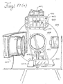
- FIG. 2 Another example of a known auxiliary cone beam computerized tomography imaging system is shown in FIG. 2 .
- the auxiliary cone beam computerized tomography imaging system 200 replaces the CCD-based imager of FIGS. 1 (a)- (c) with a flat-panel imager.
- the imaging system 200 consists of a kilovoltage x-ray tube 202 and a flat panel imager 204 having an array of amorphous silicon detectors that are incorporated into the geometry of a radiation therapy delivery system 206 that includes an MV x-ray source 208.
- a second flat panel imager 210 may optionally be used in the radiation therapy delivery system 206.
- Such an imaging system 200 could provide projection radiographs and/or continuous fluoroscopy of the lesion 212 within the target volume as the patient 214 lies on the treatment table 216 in the treatment position. If the geometry of the imaging system 200 relative to the system 206 is known, then the resulting kV projection images could be used to modify patient setup and improve somewhat the precision of radiation treatment. However, such a system 200 still would not likely provide adequate visualization of soft-tissue structures and hence be limited in the degree to which it could reduce errors resulting from organ motion.
- the present invention provides a planning process for use in on-line cone beam computerized tomography guidance of radiation therapy procedures according to claim 1. It involves a radiation therapy system that includes a radiation source that moves about a path and directs a beam of radiation towards an object and a cone-beam computer tomography system.
- the cone-beam computer tomography system includes an x-ray source that emits an x-ray beam in a cone-beam form towards an object to be imaged and an amorphous silicon flat-panel imager receiving x-rays after they pass through the object, the imager providing an image of the object.
- a computer is connected to the radiation source and the cone beam computerized tomography system, wherein the computer receives the image of the object and based on the image sends a signal to the radiation source that controls the path of the radiation source.
- Also disclosed is a method of treating an object with radiation that includes moving a radiation source about a path, directing a beam of radiation from the radiation source towards an object and emitting an x-ray beam in a cone beam form towards the object.
- the method further includes detecting x-rays that pass through the object due to the emitting an x-ray beam with an amorphous silicon flat-panel imager, generating an image of the object from the detected x-rays and controlling the path of the radiation source based on the image.
- the present disclosure provides the advantage of generating KV projection images in a cone beam computerized tomography system that provide adequate visualization of soft-tissue structures so as to reduce errors in radiation treatment resulting from organ motion. structures so as to reduce errors in radiation treatment resulting from organ motion.
- the present disclosure provides an apparatus and method for improving the precision of radiation therapy by incorporating a cone beam computerized tomography imaging system in the treatment room, the 3-D images from which are used to modify current and subsequent treatment plans.
- the present disclosure represents a significant shift in the practice of radiation therapy. Not only does the high-precision, image-guided system for radiation therapy address the immediate need to improve the probability of cure through dose escalation, but it also provides opportunity for broad innovation in clinical practice.
- the present disclosure may permit alternative fractionation schemes, permitting shorter courses of therapy and allowing improved integration in adjuvant therapy models.
- the present disclosure provides valuable imaging information for directing radiation therapy also provides an explicit 3-D record of intervention against which the success or failure of treatment can be evaluated, offering new insight into the means by which disease is managed.
- a bench-top cone beam computerized tomography (CBCT) system 300 is shown in FIG. 3 , according to an example of the present disclosure.
- the CBCT system 300 was constructed to mimic the geometry of the CBCT scanner currently installed on a linear accelerator, with a source-to-axis distance of 1000 mm and a source-detector distance of 1600 mm.
- the primary components of the system 300 include an x-ray tube 302, a rotation stage 304 and flat-panel imager (FPI) 306. These components are rigidly mounted to an optical bench 308.
- the relative position of these components is controlled by three translation stages, including an xobject stage 310, a yobject stage 312 and a yimage stage 314, which are used during initial setup to accurately determine and control the imaging geometry.
- the cone beam computerized tomography system 300 generates images of an object 316, identified throughout as a phantom, mounted on the rotation stage 304.
- Each stage 310, 312 and 314 contains a home or limit switch, and the imaging geometry is referenced to the location of these switches with a reproducibility of ⁇ 0.01 mm.
- the specific geometries used in the discussion herein are shown in FIG. 4 , and are set to simulate the imaging geometry that would be implemented for a cone beam computerized tomography system incorporated on a radiotherapy treatment machine. Table 1 below shows the parameters of the system 300.
- a set of alignment lasers 318 allow visualization of the axis of rotation 320 and the source plane perpendicular to the axis of rotation 320 and intersects focal spot 322 of the x-ray-source-or-tube 302.
- the axis of rotation 320 is positioned such that it intersects the central ray 324 between the focal spot 322 and the detector plane 326 (+0.01 mm).
- the flat plane imager 326 is positioned such that the piercing point (i.e., the intersection of the central ray and the image plane) is centered on the imaging array (i.e., between columns #256 and #257, ⁇ 0.01 mm), with a quarter-pixel offset applied to give improved view sampling for cone beam computerized tomography acquisitions in which the object 316 is rotated through 360°.
- the stage 310 is controlled manually by means of a positioning micrometer.
- the source-to-object (SOD) and source-to-image (SID) distances were measured to within ⁇ 0.5 mm and give an objection magnification of 1.60, equal to that of the imaging system on the linear accelerator.
- the cone angle for this geometry is -7.1.
- Radiographic exposures used in the acquisition procedure are produced under computer control with a 300 kHU x-ray tube 302, such as General Electric Maxi-ray 75 and a 100 kW generator, such as the General Electric MSI-800.
- the tube 302 has a total minimum filtration of 2.5 mm A1, with an additional filtration of 0.127 mm Cu to further harden the beam, and a nominal focal spot size of 0.6 mm.
- the 100 kV beam is characterized by first and second HVLs of 5.9 and 13.4 mm A1, respectively.
- the accelerating potential of the generator was monitored over a one-week period and was found to be stable to within ⁇ 1%. All exposures were measured using an x-ray multimeter, such as the RTI Electronics, Model PMX-III with silicon diode detector.
- the exposures for the cone beam computerized tomography acquisitions are reported in terms of exposure to air at the axis of rotation 320 in the absence of the object 316.
- the same method of reporting exposure can be used for the images acquired on the conventional scanner.
- the exposure per unit charge is measured with the gantry rotation disabled and the collimators set for a 10 mm slice thickness, thereby guaranteeing complete coverage of the silicon diode.
- the exposure per unit charge at 100 kVp was 9.9 mR/mAs and 14.9 mR/mAs for the bench-top and conventional scanners, respectively.
- the flat panel imager 306 can be the EG&G Heimann Optoelectronics (RID 512-400 AO) that incorporates a 512 x 512 array of a-Si:H photodiodes and thin-film transistors.
- the electro-mechanical characteristics of the imager are shown in Table 1.
- the flat plane imager 306 is read-out at one of eight present frame rates (up to 5 frames per second) and operates asynchronously of the host computer 328 schematically shown in FIG. 4 .
- the analog signal from each pixel is integrated by ASIC amplifiers featuring correlated double-sampling noise reduction circuitry. Digitization is performed at 16 bit resolution. The values are transferred via an RS-422 bus to a hardware buffer in the host computer 328.
- the processor in the host computer 328 is interrupted when a complete frame is ready for transfer to host memory.
- the cone-beam scanning procedure includes a repeated sequence of radiographic exposure, array readout, and object rotation.
- the timing of this procedure is driven by the asynchronous frame clock of the flat plane imager readout electronics. A conservative frame time of 6.4 s was used.
- the host computer advances the motorized rotation stage 304 and triggers the x-ray generator or tube 302.
- the rotor of the x-ray tube 302 remains spinning throughout the scanning procedure.
- the control software allows the operator to specify the number of frames between exposures. This was designed as a mechanism to investigate methods of reducing the amount of lag in sequential projections.
- the detector signal from a group of nine pixels in the bare-beam region of the flat plane imager 306 is monitored to measure and verify the stability of each radiographic exposure. Exposures outside tolerance are trapped and repeated at the same projection angle. Each projection image is written to hard disk between frame transfer and motor rotation. After the projections are acquired, a set of flood and dark field images (20 each) are collected to construct gain and offset images for flat-field processing of the projection images.
- median filtration is performed using a pre-constructed map of unstable pixels.
- the signal in each projection is normalized to account for small variations in x-ray exposure, this is performed using a cluster of nine pixels in the periphery of the detector well outside the objects shadow.
- a volumetric computerized tomography data set is reconstructed from the projections using a filtered back-projection technique.
- the filter used in the reconstruction is constructed using Webb's three-parameter formula. The parameters and their corresponding values are shown in Table 1.
- the reconstruction field of vision is limited to a 12.4 cm diameter cylinder, approximately 12.1 cm in length; the lateral extent of objects to be reconstructed must lie well-within this cylinder.
- the voxel values in the resulting volumetric data sets are scaled linearly to produce a mean CT number of zero in air and 1000 in water.
- the time required to filter (100 element kernel) and back-project a single projection (512 x 512) on to a 281 x 281 x 500 voxel data set was 1 minute and 21 seconds.
- the basic signal and noise characteristics of the flat plane imager 306 were measured.
- the detector gain and linearity are presented in FIG. 5(a) .
- the detector gain was measured to be 18.2 x 10 5 e/mR/pixel (17.8 x 10 6 e/mR at 100 kVp).
- the detector exhibits excellent linearity with exposure up to 50% of its sensitive range (5 mR).
- the various additive electronic noise sources and their magnitudes are listed in Table 1.
- the total additive electronic noise is found to depend upon frame time, ranging from 13,300 e at a frame time of 200 ms to 22,500 e at a frame time of 25.6s.
- the amplifier noise (12,700 e) is the dominant component at high frame rates.
- the significance of amplifier noise on the zero-frequency detective quantum efficiency (DQE) was studied using a cascaded system model that analyzes signal and noise propagation in the FPI 306.
- FIG. 5(b) shows the dependence of detective quantum efficiency on exposure for the RID 512-400AO, as well as for two hypothetical imagers with reduced amplifier noise.
- the primary quantum efficiency for the detector is approximately 0.57; losses due to energy absorption noise and additive sources reduce the detective quantum efficiency to ⁇ 0:41 for exposures above 1 mR.
- the detective quantum efficiency falls rapidly for amplifier noise values comparable to that found in the EG&G detector.
- improvements in amplifier noise (and/or x-ray converter, e.g. Csl;Tl) will significantly improve detective quantum efficiency.
- FIG. 5(c) The temporal stability of the detector dark signal is presented in FIG. 5(c) .
- This plot corresponds to a selected group of 'typical' pixels.
- the dark signal drifts significantly during the first 2 h of operation, which correlates with the change in temperature within the flat panel imager enclosure. After the temperature has stabilized, the dark signal also stabilizes. Based on these results, all cone beam computerized tomography scans were performed after the array had been powered-on for at least 2 hours. In some regions of the array, the dark signal does not stabilize, even after thermal equilibrium. It is assumed that these regions are the result of variations in the array manufacturing process.
- FIG. 5(d) shows the pixel signal following a single radiographic exposure applied within the acquisition period of frame number 0. Subsequent frames exhibit lag signal ranging from ⁇ 4% to ⁇ 0.04% for frame members 1 through 9. It is interesting and important to note that the lag demonstrates a dependence not upon frame time, but also exclusively upon the number of frames.
- the projections Prior to reconstruction, the projections are corrected for stationary pixel-to-pixel variations in offset and gain. Defective pixels with significant variations in dark field signal or with aberrant signal response are median filtered. The resulting projections are padded by an additional 128 columns prior to reconstruction. The value of the padded pixels is set row-by-row to the average of the 7 pixels at the periphery of the array. Finally, to account for small variations in x-ray tube output, the signal in each projection is normalized using signal measured from the bare-beam monitors pixels mentioned above (nine pixels). The pre-construction processing can be performed on a 250 MHz UltraSparc processor, such as the Enterprise 450, Sun Microsystems, Sunnyvale, CA.
- Feldkamp's filtered back-projection algorithm can be used to reconstruct the data set. Images are reconstructed on a Cartesian matrix of voxels 561 x 561 x N, where the number of slices, N, depends on the object of interest. The voxel size used in these reconstructions was typically 0.25 x 0.25 x 0.25 mm. The filtering used in the reconstruction follows the formalism of Webb. Table 1 contains the three parameters that specify the filter used in these investigations. Upon completion of the reconstruction, an offset and scale parameters are constant for a 9 mm set of reconstruction and acquisition parameters. The reconstruction of the volumetric cone beam computerized tomography data sets is also performed on the UltraSparc system.
- the uniformity of response of the imaging system 300 over the three-dimensional (3-D) field-of-view (FOV) was studied by imaging a cylindrical water bath [110 mm diameter]. Scans of the same phantom were also acquired on the conventional scanner. The response was examined along both radial and vertical profiles through the reconstructed volume.
- the noise in reconstructed images of the water bath was studied as a function of x-ray exposure. Images were acquired at exposures of 131, 261, 653, 1310, 3260, and 6530 mR. The images were reconstructed on a 561 x 561 x 11 matrix with voxel dimensions of 0.25 mm on a side. For all reconstructions, the reconstruction filter was fixed at the parameters specified in Table 1. Varying these parameters can have a significant effect on the noise characteristics of the reconstructed images.
- the noise characteristics of these image sets were analyzed by analysis of the standard deviation in CT number in 5 x 5 x 1 regions throughout the data set, and by calculation of the noise power spectrum (NPS) from the 3D data sets. Both methods of analysis were performed as a function of exposure.
- the noise-power spectrum was analyzed from the volumetric data by extension of methods employed for analysis of known 2-D projection images.
- the volume data was normalized such that the mean CT number within the water cylinder was 1000.
- a tetragonal region 256 x 256 x 20 voxels
- a small number of voxel defects were 3 x 3 median filtered.
- the twenty slices were averaged along the z-direction, and it was found that averaging more slices did not affect the noise-power spectrum, i.e, the data was convergent.
- a background slice formed from the average of 81 slices in a separate scan was subtracted in order to reduce background trends. Low-frequency trends were further reduced by subtraction of a planar fit to the data, yielding a 2-D zero-mean realization.
- the two-dimensional Fast Fourier Transform (FFT) was computed from ensembles of sixteen 64 x 64 non-overlapping regions within the realization, and the results were averaged. The results were normalized to account for voxel size and for average in z, and the volume under the noise-power spectrum was compared to the square of the standard deviation.
- the resulting noise-power spectrum represents a central slice in the (u x u y ) domain, i.e., the Fourier counterpart to the (x,y) domain. Strips along the u x axis were extracted in order to show 1-D power spectra, NPS(u x ), e.g., are various exposure levels.
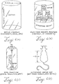
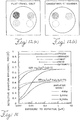
- the noise characteristics of the cone beam computerized tomography system 300 were compared to those of the conventional computerized tomography scanner. To allow meaningful comparison, the two systems must demonstrate identical response over the range of signal variation. The response was tested by scanning an electron density phantom (shown in FIG. 6(b) ) with the two systems. Seven inserts with coefficients near that of water were inserted into a 110 mm diameter water bath. The inserts are taken from the RMI electron density phantom having nominal CT numbers. In FIG.
- CT Solid Water CT#1001
- BR-SRI Breast CT# 945
- BRN-SR2 Brain CT#1005
- C133 Resin Mix C133 Resin Mix
- LV1 Liver CT#1082
- Polyethylene CT#897
- the attenuation coefficients (relative to water) reported by the cone beam computerized tomography system 300 were compared to those reported by the conventional scanner. A first-order fit to the measured data was calculated to determine the relative linearity of the two systems.
- the noise characteristics of the conventional scanner were also measured using the water cylinder test phantom described above images were acquired at 100kVp with a slice thickness of I mm at four different exposure levels (743, 1490, 2970, and 5940 mR). Three images were acquired at each exposure level. Reconstructions were performed on the conventional scanner using the 'High Res Head (#1 H)', 'Standard Head (#2)', and 'Smooth Abdomen (#3)' filters.
- the noise analysis was identical to that applied to the cone beam computerized tomography data sets. In order to compare noise results measured on each system, analysis of the cone beam computerized tomography data sets was repeated wherein the cone beam computerized tomography data was first average over 2 x 2 x 4 voxels to yield an equivalent (0.5 x 0.5 x 1 mm') voxel size to that given by the conventional scanner.
- the spatial frequency transfer characteristics of the cone beam computerized tomography system 300 were measured using a wire test object, shown in FIG. 6(c) .
- the test object consists of a 0.254 mm diameter steel wire suspended in a 50 mm diameter water bath.
- the phantom was imaged on the cone beam computerized tomography system 300 (at 100 kVp) with the wire centered on the axis of rotation 320 and with the wire located -30 mm off-axis.
- the resulting images were reconstructed on a high resolution reconstruction grid of 0.1 x 0.1 x 0.25 mm 3 using the filter described in Table 1.
- Six adjacent slices (each 0.25 mm thick) were averaged to generate a low noise point spread function (PSF).
- PSF low noise point spread function
- Orthogonal slices through the 2-D modulation transfer function were calculated by first computing the Radon transform of the point spread function (i.e., integrating along either the x or y axis), and then calculating the 1-D Fourier transform. Each 1-D profile was normalized to unity area. A correction was applied to compensate for the finite diameter of the steel wire. For purposes of comparison, the same tests were performed on the conventional scanner at 100 kVp for a slice thickness of 1.5 mm. Images were reconstructed using three different reconstruction filters ["High Res Head (#1 H),” “Standard Head (#2),” and “Smooth Abdomen (#3)”].
- the relative imaging performance of the cone beam computerized tomography system 300 and the conventional scanner were compared using phantoms and small animals.
- a simple comparison in soft-tissue detectability was performed with the phantom shown in FIG. 6(b) .
- the proximity in CT number between each of the six cylinders makes this phantom a useful test object for examining contrast sensitivity and soft-tissue detectability, images were acquired of the phantom with both the cone beam computerized tomography system 300 and conventional scanners.
- Multiple high-resolution cone beam computerized tomography slices were averaged to produce an equivalent slice thickness to that used on the conventional scanner (1.5 mm). Equivalent exposure (2980 mR) and kVp were used in the two different scans.
- a second test of soft-tissue sensitivity was performed by imaging a laboratory rat that had been euthanized for other purposes, FIG. 6(d) .
- a scanning procedure identical to that described above was used, delivering an in-air, on-axis exposure of 2980 mR at 100 kVp for both systems.
- the resulting 3-D data was reconstructed at voxel sizes of 0.25 x 0.25 x 0.25 mm 3 .
- the subject was also scanned on the conventional computerized tomography scanner at a slice thickness of 1.5 mm. This scan delivered the same imaging dose as was delivered by the cone beam computerized tomography system 300.
- six slices from the cone beam computerized tomography data set were averaged to produce a slice thickness equivalent to that of the conventional scan.
- the imagers were displayed at comparable window and level to allow comparison.
- FIGS. 7(a) - 7(d) The uniformity of response of the cone beam computerized tomography scanner shown in shown in FIGS. 7(a) - 7(d) .
- Axial and sagittal slices through the cone beam computerized tomography 3-D data set are shown.
- the images demonstrate a relatively uniform response over the entire field of view of the system.
- a slight non-uniformity of approximately 20 CT numbers (2%) is visible in the histogram equalized- regions of the images. This non-uniformity appears as a combined cupping and capping artifact.
- the radial profile ( FIG. 7(c) ) illustrates this point further by comparing to the results obtained from the conventional scanner (dotted line).
- the images in FIG. 7 also demonstrate uniform noise characteristics with few artifacts. This is the case for the full range of exposures studied.
- the magnitude and uniformity of the noise is demonstrated in FIGS. 8(a) - 8(d) .
- the noise varies to a slight degree along the radial axis and to a negligible degree along the vertical axis. A slight dependence on radial position is expected due to the differences in transmission across the cylindrical water bath.
- FIG. 8(c) also presents the measured dependence of noise on exposure [also shown below, in relation to FIG. 9(b) ].
- the cone beam computerized tomography system 300 is capable of achieving a noise level of approximately 20 CT numbers for an in-air exposure of 6560 MR at isocenter.
- the noise measured for the cone beam computerized tomography system 300 as a function of exposure is shown in the top curve of FIG. 9(b) .
- the noise is seen to decrease from -80 units at the lowest exposure examined down to -20 units at the highest.
- the CT numbers reported by the cone beam computerized tomography system 300 for a variety of materials were compared to those reported by the conventional scanner.
- the CT numbers of the cone beam computerized tomography system 300 agree well with those of the conventional scanner.
- the largest discrepancy over the range of CT numbers was 8 units, with an average discrepancy of 5.7.
- the high coefficient of correlation indicates that, over the range examined, the values reported by the cone beam computerized tomography system 300 are proportional to attenuation coefficient.
- the voxel noise of the cone beam computerized tomography system 300 and the conventional scanner was compared as a function of exposure, shown in FIG. 9(b) . Shown by the open circles and dashed lines are the results for the conventional scanner using the "High-Res Head (#!H)" and "Standard Head (#2)" reconstruction filters. In each case, the noise decreases with exposure.
- An exact comparison between the two systems requires that both data sets be reconstructed at equivalent voxel size and with the same reconstruction filter.
- the requirement for equivalent voxel size was achieved by repeating the noise analysis for the cone beam computerized tomography system 300, with the volume data averaged to give a voxel size equivalent to that of the scanner.
- FIGS. 10(a) - 10(c) Results of the noise-power spectrum measurements are summarized in FIGS. 10(a) - 10(c) .
- the 2-D noise-power spectrum in the axial plane exhibits a spectral shape typical of systems employing filtered back-projection reconstruction.
- the spectral density is reduced (but non-zero) near zero-frequency, increases at mid-frequencies due to the ramp filter (e.g., peaking around -0.5 mm -1 ), and declines at higher frequencies by virtue of the low-pass noise characteristics of the system (e.g., 2-D image blur and choice of apodisation window).
- Slices of the noise-power spectrum along the u x dimension are shown in FIG. 10(b) for various exposure levels.
- the noise-power spectrum decreases with increasing exposure. Specifically, the noise-power spectrum appears inversely proportional to exposure in a fashion consistent with the form of the numerical fits in FIG. 9(b) . As shown in FIG. 10(c) , the noise-power spectrum measured at -1.3 R (in air at isocenter) is -30 mm 3 near zero-frequency, increases by a factor of -4 at mid-frequencies, and then descends to about the initial level of spectral density at the Nyquist frequency.
- FIG. 10(c) Superimposed in FIG. 10(c) are the results measured for the conventional scanner using three reconstruction filters, and to facilitate intercomparison, noise-power spectrum results for the cone beam computerized tomography system 300 are shown for an equivalent voxel size.
- the conventional scanner exhibits a noise-power spectrum with the characteristic shape described above; however, the high-resolution #1 H filter is seen to significantly amplify high-frequency noise.
- the cone beam computerized tomography system 300 appears to exhibit low-frequency noise-power spectrum comparable to the conventional scanner using the #2 and #1 H filters.
- the choice of reconstruction filter can significantly affect noise and spatial resolution, and considering the two cases that seem most closely matched the cone beam computerized tomography system 300 - even in its initial, un-optimized configuration -- appears to provide noise performance comparable to the conventional scanner.
- the cone beam computerized tomography system 300 exhibits lower voxel noise than the conventional scanner (#1H) at low exposures.
- the cone beam computerized tomography system 300 exhibits reduced high-frequency noise-power spectrum.
- the response of the cone beam computerized tomography system 300 to the wire test object is presented in FIG. 11(a) .
- the PSF is symmetric (aside from a small streak artifact believed associated with the image lag characteristics of the system) and has a full-width at half-maximum (FWHM) of 0.6 mm.
- the system MTF is shown in FIG. 11(b) for both the on- and off-axis wire results.
- the "Standard Head (#2)" filter significantly reduces the signal pass of the system compared to the High-Res Head (#1 H)” filter.
- the results demonstrate that the MTF of the conventional scanner is comparable to that of the cone beam computerized tomography system 300 when the "High-Res Head (#1 H)” filter is used. This observation is consistent with the noise results presented in FIG. 9(b) .
- the resolution of the cone beam computerized tomography system 300 and conventional scanner have not been compared in the z-dimension. It is expected, however, that the spatial resolution of the cone beam computerized tomography system 300 in the z-dimension will be comparable to that measured in the axial plane. Of course, the spatial resolution of the conventional scanner will be limited by the selected slice thickness, which is typically 1 mm or greater. The nearly isotropic resolution of the cone beam computerized tomography system 300 is expected to be a significant advantage for detection and localization.
- FIGS. 12(a) and 12(b) show axial image slices of the low-contract phantom obtained on the cone beam computerized tomography system 300 and the conventional computerized scanner at equivalent kVp and exposure.
- the grayscale window in each case is quite narrow in order to maximize the displayed contrast, and despite the slight signal non-uniformity evident for the cone beam computerized tomography image (cupping/capping artifact discussed above) the visibility of each insert is comparable to the conventional scanner.
- the mean signal values for each material are as shown in FIG. 9(a) . Slight differences in system response (e.g., due to detector response, x-ray spectrum, etc.) can result in contract reversal for materials with CT# very close to that of water.
- the minimum detectable contrast is ideally superior for the cone beam computerized tomography system 300 (e.g., visibility of the brain and CB-3 inserts), but this remains to be verified by a more controlled, quantitative observer study.
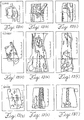
- the overall performance of the cone beam computerized tomography system 300 is demonstrated in the images of the volumetric data set illustrated in FIGS. 13(a) -13(i) .
- These images of an euthanized rat demonstrate the soft tissue sensitivity and high spatial resolution of the system.
- Example images are shown from various regions throughout the volumetric set [e.g., in regions of the lungs (a,b,c), the kidney (d,e,f), and lower spine (g,h,i)] to illustrate the quantity and uniform quality of the data produced with the cone beam computerized tomography system 300.
- the clear visualization of soft-tissue structures demonstrates the soft-tissue contrast sensitivity of the scanner.
- FIGS. 13(a) -13(c) the window and level have been set to emphasize features in the lung of the rat. In addition to the lung detail, there are some streak artifacts evident, the origin of which is unknown, but is believed to be associated with detector lag effects or beam hardening.
- FIGS. 13(d) -13(f) The soft tissue contrast sensitivity of the cone beam computerized tomography system 300 is illustrated in FIGS. 13(d) -13(f) , in which the window and level have been set to delineate fat and muscle.
- the cross-hair in each image indicates the location of the rat's left kidney.
- FIGS. 13 (g-i) The spatial resolution performance of the system 300 is demonstrated in FIGS. 13 (g-i), in which the same rat data set is displayed with window and level selected to display bony features.
- the clear visibility of the intervertebral spaces and the non-cortical bone in the pelvis is stunning. It should be kept in mind that this level of detail was produced on a cone beam computerized tomography system 300 that operates on a scale that mimics the geometry of the linear accelerator. Therefore, this level of detail would be expected in the clinical implementation of the device, given accurate correction of mechanical flex.
- the volumetric data set is illustrated further in FIG. 14 , in which volume renderings demonstrate the fully 3-D nature of the data set and show the level of detail contained within the cone beam computerized tomography data. It is interesting to note that all the data presented in FIGS. 13 and 14 were obtained from a single acquisition performed in a single rotation.
- FIGS. 15(a) - 15(b) show an axial slice of the rat acquired on the two systems.
- the images produced by the two systems are of comparable quality both in terms of spatial resolution and contrast sensitivity.
- the flat panel imager-based cone beam computerized tomography image exhibits extraordinarily spatial resolution and provides clear delineation of soft-tissue boundaries and detail in the gut.
- the spatial resolution of the cone beam computerized tomography system 300 appears to exceed that of the conventional scanner; however, it must be noted that restrictions in available reconstruction matrices for the conventional computerized tomography scanner limited the voxel size to twice that of the cone beam computerized tomography image. Lack of obvious pixelation in the flat panel imager-based cone beam computerized tomography image indicates that this level of detail represents the physical limits in spatial resolution of the current system.
- the objective of these investigations is to evaluate the applicability of flat-panel technology as a detector in a cone beam computerized tomography system, specifically, a tomographic imaging system for use in the guidance of radiation therapy on a medical linear accelerator.
- the zero-frequency detected quantum efficiency was computed using a model for signal and noise transfer that has demonstrated excellent agreement with measurements. It is clear from FIG. 16 that improvements in the x-ray converter and electronics noise significantly reduce the exposure dependency of the detected quantum efficiency over the broad range of exposures required for computerized tomography. The magnitude of the reduction depends greatly on the amplifier noise in the system. For the prototype imager used in these studies, the amplifier noise is very high at 12,700 e. For the low transmitted exposure levels in computerized tomography of pelvic anatomy, for example, this detector would achieve a zero-frequency detected quantum efficiency of less than 10%.
- an imager than incorporates the recent advances in design listed above (e.g., a high-quality Csl:Tl converter and amplifier noise of 3000 3 or better) would achieve a higher detected quantum efficiency (-65%) at full transmission and maintain a detected quantum efficiency of >40% even at the low exposure levels.
- Such enhancements in imager design are within the current capabilities of flat panel imager manufacturers and will greatly facilitate the application of flat panel imagers in cone-beam computerized tomography of human beings. Furthermore, these improvements are largely driven by other forces in digital imaging that anticipates use of flat panel imagers in place of conventional image-intensifier systems for interventional fluoroscopy. For this reason, it can be expected that imagers with such characteristics will be available within the next five years.
- flat panel detectors are geometrically robust under a rotating geometry, eliminating concerns of image distortion.
- the proximity of the analog-to-digital converter to the pixel element and the relatively large charge signals make the panels robust in high radio-frequency power environments; this is of particular interest for radiotherapy applications.
- the high readout rate of these detectors allows for imaging sequences of 300 projection images to be acquired within 10 seconds (operating at 30 fps). This is more than sufficient to satisfy the allowable rotation rates for the gantry of a medical linear accelerator.
- Imaging systems based on this technology can be constructed to address specific imaging' problems, including non-destructive testing (at kilovoltage or megavoltage energies), early detection and monitoring of specific medical conditions, and, of course, navigational imaging for therapies.
- the compact nature of the panels allow flat panel imager-based cone beam computerized tomography imagers to be applied in situations that would never be considered feasible for a conventional computerized tomography scanner.
- the cone beam computerized tomography approach offers two important features that dramatically reduce its cost in comparison to a conventional scanner. First, the cone-beam nature of the acquisition does not require an additional mechanism to move the patient (or object) during image acquisition.
- the use of a cone-beam significantly increases the x-ray utilization, lowering the x-ray tube heat capacity required for volumetric scanning.
- the efficiency roughly scales with the slice thickness.
- the x-ray utilization increased by a factor of 30 in going from a 3 mm slice in a conventional scanner to a cone-angle corresponding to a 100 mm slice with a cone-beam system, This would decrease heat-load capacities dramatically. From our experience, a 5200 kHU x-ray tube costs approximately $70, 000, whereas a 600 kHU x-ray tube (a factor of -10 lower in capacity) costs roughly $6, 000.
- Cone-beam computed tomography has been a topic of active research and development for over a decade in areas such as nuclear medicine and industrial testing ; however, only recently has it begun to appear in the diagnostic computerized tomography arena. The developments in this area have been for the most part limited to multi-slice detectors. In this investigation, the use of an alternative detector for high-quality computerized tomography has been studied.
- FIGS. 17 (a)- (e) and 18 are diagrammatic and schematic views of an example of a wall-mounted cone beam computerized tomography system 400.
- the cone beam computerized tomography system 400 includes an x-ray source, such as x-ray tube 402, and a flat-panel imager 404 mounted on a gantry 406.
- the x-ray tube 402 generates a beam of x-rays 407 in the form of a cone or pyramid that have an energy ranging from approximately 30KeV to 150 KeV, preferably approximately 100 KeV.
- the flat-panel imager 404 employs amorphous silicon detectors.
- the system 400 may be retrofitted onto an existing or new radiation therapy system 700 that includes a separate radiation therapy x-ray source, such as a linear source 409, thatoperates at a power level higher than that of x-ray tube 402 so as to allow for treatment of a target volume in a patient.
- the linear source 409 generates a beam of x-rays or particles 411, such as photons or electrons, that have an energy ranging from 4 MeV to 25 MeV.
- the system 400 may also include an imager (not shown) that is aligned with the linear source 409 with the patient interposed therebetween. The imager forms projection images of the patient based on the remnants of the beam 411 that passes through the patient.
- the x-ray sources 402 and 409 may be separate and contained with the same structure or be combined into a single source that can generate x-rays of different energies.
- the flat-panel imager 404 can be mounted to the face of a flat, circular, rotatable drum 408 of the gantry 406 of a medical linear accelerator 409, where the x-ray beam 407 produced by the x-ray tube 402 is approximately orthogonal to the treatment beam 411 produced by the radiation therapy source 409. Attachment of the flat plane imager 404 is accomplished by an imager support system 413 that includes three 1m long arms 410, 412 and 415 that form a tripod.
- Side arms 410 and 415 are identical to one another in shape and have ends attached to a Ax95 Guy pivot 417 which in turn is attached to a mounting 414 by screws that are threaded through aligned threaded holes of the pivot 417 and threaded holes 425 and 431 of plates 433 and 435, respectively, as shown in FIGS. 18 and 19(a)-(b) .
- the mountings 414 for the arms 410 and 415 are aligned with one another along a line segment 419 that is contained within a plane 421 that is parallel to and offset by approximately 30 cm from the plane containing the flat-plane imager 404.
- the mountings 414 are separated from one another by approximately 70 cm and are symmetrically positioned with respect to a plane bisecting an imager mount 423 that is attached to the drum 408 270o from the radiation therapy source 409.
- each mounting 414 is attached to an end portion 416 of the drum 408 by inserting a threaded male member 418 through an opening 437 formed through the drum 408. Once inserted, the male member 418 is attached to the drum 408 by tightening a nut 420 onto the threaded male member 418.
- the other ends of the arms 410 and 415 are attached to Ax95 Guy pivots 422 attached to the back of an 3/8 inch thick Aluminum square plate 424 is attached to the rear of the flat-panel imager 404 via bolts (not shown).
- FIGS. 17(d)-(e) there are two preset positions of the flat panel imager 404 relative to the plate 424.
- the flat panel imager 404 is centered about the ends of the arm 412.
- an offset flat panel imager 404 can be used as shown in FIG. 17(e) where the imager 404 is attached to a side of the plate 424 via bolts. Note that it is possible to use a motorized system to move the flat panel imager 404 relative to the plate 424 to provide an easy way to vary the field of view of a cone beam computerized tomography system.
- a center arm 412 is also attached to the drum 408 and the flat-panel imager 404.
- the center arm 412 has one end attached to Ax95 Guy pivot 427 that is in turn attached to a tapped, triangular-shaped, reinforcing plate 426 formed on the drum 408 as shown in FIGS. 17(b) and 18 .
- the plate 426 is approximately 433.8mm from the rotational axis 428 that intersects the iso-center 430 of the imaging system 400.
- a second end of the center arm 412 is attached to the plate 424 via a Cx95A right angle joint 425.
- the end of the arm 412 lies along a line that is the perpendicular bisector of the line segment 419 and is radially separated from the midpoint between mountings 414 as measured along line segment 419 by a distance D of approximately 30 cm.
- the other ends of the arms 410, 412 and 415 are attached to the plate 424 so as to be positioned approximately 20 cm from the rear edge 429 of the plate 434 and approximately midway between the left and right edges of the plate 434.
- the arms 410, 412 and 415 are attached to the drum 408 and the plate 424, the arms can be pivoted so that the flat panel imager 404 moves to a position where its rear side is separated from the iso-center 430 by a distance L of approximately 600 mm.
- One advantage of the imager support system 413 is that it can be used to retrofit existing stand-alone radiation treatment devices so they have the capability to have a flat panel imager attached thereto.
- the imager support system 413 is very rigid, i.e., constant tension and compression, which reduces movement of the imager 404 and so leads to cleaner imaging data.
- the x-ray tube 402 can also be retrofitted onto an existing stand-alone treatment device so as to be positioned opposite to the flat panel imager 404.
- the x-ray tube 402 is attached to tube support 440 that is composed of a pair of front and rear faces 442 and 444 and a pair of side faces 446.
- a multi-leaf collimator 448 is supported within the interior of the tube support 440.
- the front and rear faces 442 and 444 each include three openings 450, 452 that are aligned with one another and receive three cylindrical support arms 454 that are attached to a bearing housing 456 that is bolted to the drum 408.
- the tube support 440 and the xray tube 402 are able to slide along the support arms 454.
- a cable support 458 spans between the tube support 440 and the bearing housing 456 and contains the wiring necessary to operate the x-ray tube 402.
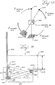
- FIGS. 20 (a)- (b) An alternative imager support system for the flat panel imager 404 of FIGS. 17 is shown in FIGS. 20 (a)- (b) .
- the imager support system 507 shown in FIGS. 20 (a)- (b) includes a single pivoting arm 510 that has one end 511 pivotably attached to a lower corner of the radiation therapy source 409. The other end 512 of the arm 510 is pivotably attached to an end of the flat-panel imager 404.
- the arm 510 and flat-panel imager 404 are movable from a retracted position of FIG. 20 (a) to an extended position of FIG. 20 (b) and vice versa. Movement of the arm 510 and the flat-panel imager 404 may be moved either manually or via a motor.
- the x-ray tube 402 is attached to a second lower corner of the radiation therapy source 409 in order to simplify the support structure and reduce the mechanical complexity of the overall system.
- the position of the x-ray tube 402 also reduces interference with staff access to the patient.
- the distance from the x-ray tube 402 to the axis of rotation 428 is not necessarily equal to the distance from the radiation therapy source 409 to the axis of rotation 428.
- the amount of extension of the arm 510 shown in FIG. 20 (b) will vary depending on the desired field of view for cone beam computerized tomography imaging.
- the arm 510 can move in and out during image acquisition during gantry rotation so as to allow the imager 404 to dynamically avoid potential rotation-induced collisions with the patient or the table.
- the head of the radiation therapy source 409 can be altered to provide additional lead shielding on the imager side to limit radiation induced damage to the imager 404 while in the retracted position of FIG. 20 (a) . This will increase the life span of the imager 404.
- FIGS. 21 (a)- (b) A second alternative imager support system for the flat panel imager 404 of FIG. 17 is shown in FIGS. 21 (a)- (b) .
- the imager support system 607 shown in FIGS. 21(a)- (b) includes a single C-arm 610 that is attached to an arm support 611 that is attached to the front or rear of the radiation therapy source 409. At one end of the C-arm 610 the x-ray tube 402 is attached and at the other end the flat-panel imager 404 is attached.
- the Carm 610 is moved either manually or by a motor within the arm support 611, so that the x-ray tube 402 and the flat-panel imager 404 can move along an arc.
- the distance from the x-ray tube 402 to the axis of rotation 428 is not necessarily equal to the distance from the radiation therapy source 409 to the axis of rotation 428.
- the arm 610 does not necessarily be in the shape of an arc of a circle.
- the axis of rotation of the arm 610 is not necessarily coincident with the axis of rotation 428 of the radiation therapy source 409, which allows the same device to be fitted on machines with different face-to-isocenter distances without altering the radius of the C-arm 610.
- image data can be obtained by only having the drum 408 of the gantry 406 rotate.
- Image data can be obtained in a second manner by having the C-arm 610 move independently of the gantry 406 in a circular path.
- Image data can be obtained by having the C-arm 610 and the drum 408 work cooperatively to generate images along a circular path so that the angular range of acquisition is increased and so instabilities in the angular velocity of the gantry are addressed.
- a fourth manner of imaging involves rotating the drum 408 and pivoting the C-arm 610 about the mounting point on the gantry 406 with a sinusoidal pattern to effect non-circular orbits that involve a sinusoidal trajectory on a spherical surface. Such a non-circular orbit allows more complete image reconstructions by satisfying Tuy's condition.
- FIG. 22 shows a portable cone beam computerized tomography system 700.
- the system 700 is on a mobile platform 702 so that it can be moved relative to a patient 441 positioned on a table 443 relative to a rotating radiation therapy source 409 (not shown).
- the cone beam computerized tomography system 700 includes an x-ray source, such as x-ray tube 402 positioned on one side of a C-arm 704, and a flat-panel imager 404 positioned on an opposite side of the C-arm 704.
- the C-arm 704 can rotate about two axes of rotation when in operation.
- the system 700 can be moved to a radiation therapy system (not shown) and can be used to generate images that aid in the alignment of the radiation therapy system.
- the term “shape” of the radiation therapy beam 411 is understood to refer to the spatial distribution of the beam in a plane perpendicular to the direction of the beam or to the frequency modulation of the beam after being transmitted through some beam-limiting device.
- planning image refers to an image of the patient acquired by the cone beam computerized tomography system 400 prior to treatment delivery used for radiation therapy treatment planning.
- constrained plan set refers to a plurality of radiation therapy treatment plans for a given patient, where each radiation therapy treatment plan is calculated assuming some perturbation of lesion location and/or orientation compared to that in the planning image. For example, a constrained plan set could be calculated where each plan corresponds to a different magnitude of lesion rotation about the y and/or z axes.
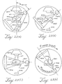
- the cone beam computerized tomography imaging system 400 preferably includes an x-ray tube 402 and a flat panel imager 404 in any one of the geometries illustrated in FIGS. 23(a)-(d) , capable of forming 3-D images of the patient on the treatment table in the treatment position.
- the x-ray tube 402 may be operated so as to produce a pulsed or continuous beam of x-rays 407.
- the flat panel imager 404 includes an active matrix of imaging pixels incorporating mechanisms for: 1.) converting incident x-rays to electronic charge (e.g., a scintillator in combination with optically sensitive elements at each pixel, or a photoconductor); 2.) integrating and storing the electronic charge at each pixel (e.g., the capacitance of photodiode(s), capacitors, etc. located at each pixel); and 3.) reading the electronic charge out of the device (e.g., a thin-film transistor switch or the like at each pixel, with associated switching control lines and readout lines).
- the x-ray tube 402 and the flat panel imager 404 preferably move in a circular orbit (or variation thereof) about the longitudinal axis of the patient.
- the imager support system should accommodate offsets in the x and/or z directions as illustrated in FIG. 23(b) .
- the combined motion of the x-ray tube 402 and/or the flat panel imager 404 in x, y, and/or z is termed the orbit, and may be circular about the patient, or non-circular, e.g., comprising of some combination of linear, sinusoidal, circular, and/or random paths.
- the source 402 and imager 404 move independently with respect to one another
- the source 402 can move on a sinusoidal or sawtooth path constrained to the surface of a cylinder while the imager 404 moves in a circular path on the surface of a cylinder.
- the collimator adjusts in real time the shape of the radiation field so it is confined to the imager 404 despite the allowed independent motion of the source 402 and imager 404.
- Cone beam computerized tomography image acquisition involves acquisition of a plurality of 2-D images, where each image preferably corresponds to a different orientation of the x-ray beam 407 and the flat panel imager 404 with respect to the patient 441, e.g., where the x-ray tube 402 and the flat panel imager 404 traverse a circular or non-circular path about the patient 441 as illustrated in FIG. 23 (d) .
- the cone beam computerized tomography image is preferably acquired with the patient on the treatment table, in the treatment position, and immediately prior to treatment delivery.
- FIG. 24 The processes involved in the preferred method for cone beam computerized tomography image acquisition are illustrated in FIG. 24 , divided conceptually into a variety of off-line and on-line processes, and mechanisms for 2-D image acquisition and 3-D image reconstruction.
- the off-line processes schematically shown in FIG. 24 include acquisition of a plurality of 2-D images acquired in the absence of x-ray irradiation (termed dark fields) and with uniform x-ray irradiation (termed flood fields). Such dark and flood fields are used to correct stationary nonuniformities in the imaging system arising from nonuniformity in pixel operational and response characteristics. Also included is a mechanism for identifying and correcting defective pixels in the 2-D images (e. g., a pixel defect map that identifies aberrant pixel coordinates, and application of a filter to the corresponding pixel values). Thirdly, a measure and process for correction of orbit non-idealities, described below, is preferably employed.
- the on-line processes schematically shown in FIG. 24 include : 1.) control and monitoring of the x-ray tube ; 2.) control and monitoring of the orbit traversed by the x-ray tube 402 and the flat panel imager 404 (e. g., by rotating the gantry 406) ; and 3.) control and readout of the flat panel imager 404.
- the x-ray source 402 produces x-rays in either a pulsed or continuous manner, and variations in the magnitude of x-ray tube output are monitored by an output monitor, which preferably includes a radiation sensitive electronic device such as a diode placed inside the x-ray tube collimator assembly.
- the output monitor could be placed outside the x-ray tube 402 in a position that allows it to measure variations in x-ray tube output, or the output could be measured using pixels on the flat panel imager 404, such that these pixels are not occluded by the patient in the plurality of 2-D projection images.
- the orbit of the x-ray tube 402 and the flat panel imager 404 about the patient is preferably controlled via computer controlled rotation of the gantry 406, combined with a precise measurement of the gantry angle at which each 2-D image is acquired.
- the x-ray source 402 and the flat panel imager 404 are not both mounted on the treatment gantry 406, such as the portable example of FIG.
- a similar mechanism for measuring and recording the location of these two components for each 2-D image is employed.
- a plurality of 2-D images are read from the flat panel imager 404 by a controVacquisition computer.
- the readout of the flat panel imager 404 is preferably synchronized with the operation of the x-ray tube 402 as well as with the rotation of the x-ray tube 402 and the flat panel imager 404 support structure (s), such as those described previously with respect to FIGS. 18-22 .
- the timing of x-ray exposures, gantry rotation, and flat panel imager readout is preferably synchronized by : 1.) the control/acquisition computer; or 2.) an external trigger mechanism (gating source), such as a device for active breathing control, electrocardiac gating, etc.
- the preferred example includes computer-control of : 1.) x-ray pulses generated by the x-ray source 402 ; 2.) gantry rotation (e. g., in increments of ⁇ 1 through ⁇ 360) ; and flat panel imager readout (e. g., at a readout rate consistent with the limitations in x-ray tube output and gantry rotation).
- the preferred example is such that the gating source triggers x-ray production, gantry rotation, and flat panel imager readout in a manner synchronized with the motion of anatomical structures in the patient 441 in order to reduce the deleterious effects of organ motion in image reconstructions.
- the preferred example includes a mechanism (reconstruction engine) for high-speed cone beam computerized tomography image reconstruction.
- the plurality of 2-D projections is first processed by dark and flood field correction, and the measurements of orbit non-ideality (below), tube output variations, and gantry rotation are used together with the processed 2-D projections to form 3-D cone beam computerized tomography image reconstructions of the patient 441.
- a variety of cone-beam reconstruction techniques are known within the art, including cone-beam filtered back-projection.
- the cone beam computerized tomography image is then made available to a system for on-line treatment planning.
- the patient 441 is preferably monitored by periodic radiographs obtained with the flat panel imager at one or more gantry angles.
- these monitor radiographs are analyzed (e. g., by calculation of difference images) in order to provide a check against intrafraction motion of the patient 441.
- the preferred example includes a computer-controlled treatment table 443 for correction of lesion localization errors.
- the table 443 preferably allows translation of the patient 441 in the x, y, and z directions as well as rotation about the x axis. Rotation about the y axis (tilt) and z axis (roll) is possible for an example in which lesion localization errors are corrected by such motions (as opposed to correction of such errors through selection of an appropriate RTTP from a constrained plan set), provided that such motions do not cause uncertainty in the location/orientation of the lesion 444 and/or surrounding structures, e. g., due to the effects of gravity.
- the treatment table 443 is preferably constructed of radio-translucent material so as not to interfere significantly with the acquisition of cone beam computerized tomography images.
- the preferred example includes a method for calibration of the radiation therapy delivery system accomplished using a radiation therapy system including the radiation therapy source 409, a collimating structure such as a multi-leaf collimator, and an imager 446.
- the imager 446 is located opposite the radiation therapy source 409 on a support arm attached to the radiotherapy gantry 406 and in the preferred example is a flat panel imager 404 designed for imaging of the high energy beam 411.
- the calibration method preferably employs a reference BB 448 embedded in a lucite cube 450 and located at a known location with respect to the isocenter 430 of gantry rotation, as illustrated in FIG. 25 .
- the cube 450 is precisely leveled, and marks on the cube surface project the location of the isocenter within the cube.
- the reference BB 448 is imaged at angular increments using the radiation therapy source 409 and imager 446 as the gantry 406 rotates through 360 , preferably clockwise and counterclockwise. In each image, the reference BB 448 is located preferably by an automated centroid calculation, and the edge of each leaf of the multi-leaf collimator and the edge of the collimators are localized by calculation of maximum signal gradient. After subtracting a sinusoid of specified amplitude from the measured deflections, the residuals represent imperfections in leaf placement. These residuals can then be incorporated into the controller of the multi-leaf collimator and calibrated out.
- An alternative approach is to modify the planning system to generate"corrected"leaf positions. After calibration, the patient positioning lasers in the treatment room are adjusted to the set of laser alignment marks located on the lucite cube.
- the preferred example furthermore includes a calibrator that calibrates the cone beam computerized tomography imaging geometry relative to that of the radiation therapy source 409.
- Calibration of the cone beam calibration tomography geometry is preferably performed immediately following multi-leaf collimator leaf calibration, without moving the reference BB 448.
- the same procedure is performed using the x-ray source 402 and the flat panel imager 404 ; however, in this case, the residuals are used to adjust the back-projection trajectories in the reconstruction process.
- the image of the localized BB 448 is preferably analyzed using a 3-D centroid algorithm, and the location of isocenter 430 is calculated as a simple offset from the centroid.
- the isocenter 430 can thus be explicitly identified within the 3-D matrix of cone beam computerized tomography images.
- the cross-calibration of the cone beam computerized tomography imaging system 400 and the radiation therapy delivery system can be tested with a mechanism (phantom) for combined geometry and dosimetry measurement.
- the phantom preferably includes a water-filled or water-equivalent volume in which a dosimetry insert is rigidly placed at various locations.
- the dosimetry insert preferably contains either: 1.) a detector matrix of electronic dosimeters, or 2.) a volume of radiosensitive. gel dosimeter.
- the dosimeters are embedded in a water-equivalent insert and placed asymmetrically to allow unambiguous identification in a computerized tomography image ; furthermore, each dosimeter is sufficiently small as to have legible influence on the dosimetry of other detectors.
- the electronic signals from the dosimeter matrix are preferably used in either of two ways : 1.) the dosimetry of a complete delivery can be tested by recording the signal from all detectors and comparing to calculations, thereby providing a point dose verification of the delivery as well as routine pre-treatment quality assurance ; and/or 2.) the precision and accuracy of the combined imaging and delivery system can be measured by recording the dose to the detectors as the geometric edge of a leaf can be inferred and compared to the planning system dose calculation. This test is preferably performed for all the leaves in the system by moving the location of the dosimetry insert within the volume. In the case of a radiosensitive gel dosimeter, measurement of 3-D dose distributions delivered by a given treatment scheme can be quantitatively evaluated.
- the preferred example furthermore includes delineating the target volume immediately following acquisition of the cone beam computerized tomography image of the patient 441 on the treatment table 443 in the treatment position.
- Localization of the target volume/lesion 444 and/or surrounding structures can be performed manually, e. g., by contouring of structures in some combination of transaxial, sagittal, coronal, and/or oblique slices.
- the target volume/lesion 444 and/or surrounding structures can be delineated by an automated localization algorithm, as recognized in the art.
- the target volume/lesion 444 defined in the planning image is overlaid on a given on-line cone beam computerized tomography image, and the images are matched, e.
- the treatment plan for the current session can be modified based on the cone beam computerized tomography image data by a number of methods or combinations therein, including recalculation of the RTTP, selection of a modified RTTP from a previously calculated set of plans, and/or translation, rotation, and/or angulation of the patient.
- the method chosen should provide a modified plan for the current treatment session in a manner that does not cause uncertainty in the location/orientation of the lesion ; therefore, the method should be completed within a short time frame in order to minimize intrafraction organ motion effects, and should not significantly distort patient anatomy.
- Recalculation of the RTTP based on the cone beam computerized tomography image data should be consistent with such time constraints.
- translation, rotation, and/or angulation of the patient should not perturb patient anatomy compared to that measured in the cone beam computerized tomography image, e. g., due to the effects of gravity.
- the preferred example entails a streamlined process for rapid lesion localization, selection of an appropriate RTTP, dosimetry review, and transfer of the prescription to the radiation therapy delivery system.
- the process for on-line cone beam computerized tomography guidance of radiation therapy procedures is illustrated in FIG. 26 , which conceptually separates the system into : 1.) the offline treatment process ; 2.) priors for on-line selection and correction ; and 3.) the on-line imaging and treatment process.
- the off-line treatment process of the invention begins with a planning image on which contours of the target volume and surrounding structures are defined, and margins for target deformation, delivery precision, and delineation precision are applied.
- Inverse planning is performed according to a given protocol for radiation therapy of the given treatment site, e. g., a number of radiation therapy beams 411 directed at the patient 441 from various angles, with target dose uniformity and normal tissue volume constraints to match the prescription.
- a plurality of additional plans (the constrained plan set) are generated as a function of various translations and/or rotations of the target volume. Plans are preferably generated at small increments of each possible translation and/or rotation (e. g., rotation of the target volume about the yaxis).
- the target volume/lesion 444 and its relationship to bony structure in the planning image are prepared for use as priors, and the constrained plan set is transferred to the radiation therapy system to verify deliverability prior to the on-line procedure.
- the patient 441 is set up on the treatment table 443 in the treatment position, and cone beam computerized tomography images are acquired as described above.
- the target volume/lesion 444 and surrounding structures are delineated in the cone beam computerized tomography data, thereby identifying the translations and/or rotations of the target volume/lesion 444 relative to the position and orientation in the planning image.
- translations may be corrected by translation of the computer-controlled treatment table 443, and rotations may be corrected by selection of an appropriate plan from the constrained plan set.
- the translation of the lesion 444 observed in the cone beam computerized tomography image relative to the planning image is corrected by translation of the patient 441 on the treatment table 443 in the y and/or z directions, and/or by rotation about the x axis.
- the orientation of the lesion 444 i. e., rotations about the y and/or z axes
- radiographic monitoring of the patient 441 can be used to check against intrafraction motion of the patient 441.
- a cone beam computerized tomography image acquired immediately prior to, during, or following the treatment procedure can be obtained in order to provide accurate representation of the location of patient anatomy during treatment delivery, which can be stored for off-line review, evaluation, and modification of subsequent treatment sessions.
- the treatment plan is executed according to the patient setup and treatment plan determined from the cone beam computerized tomography image.
- the cone beam computerized tomography system can be adapted to perform animal testing identification, and non-invasive and non-destructive component structural testing.
Claims (3)
- Procédé de planification destiné à être utilisé dans un guidage par tomographie informatisée à faisceau conique en ligne de procédures de radiothérapie qui implique :1) un système d'image de tomographie informatisée à faisceau conique qui comprend un dispositif d'imagerie à écran plat au silicium amorphe (404) monté sur un portique (406) et une source de rayons X keV (402) montée sur le portique et qui génère des faisceaux de rayons X sous une forme de faisceau conique en direction du dispositif d'imagerie à écran plat et2) un système source de radiothérapie comprenant : une source de radiothérapie (409) qui se déplace sur un trajet et génère un rayonnement thérapeutique, une structure de collimation et un dispositif d'imagerie (446) qui est situé en face de ladite source de radiothérapie qui génère un rayonnement thérapeutique, le procédé comprenant les étapes consistant à :acquérir une image de planification par ledit système d'image de tomographie informatisée à faisceau conique, des contours d'un volume cible d'un objet à traiter et des structures environnantes étant définis, ainsi que des marges pour une déformation cible, la précision de distribution et la démarcation appliquées sur l'image de planification ;effectuer une planification inverse selon un protocole donné pour une radiothérapie dudit objet afin de générer un plan de référence ; etgénérer une pluralité de plans supplémentaires en fonction de différentes translations et/ou rotations dudit volume cible.
- Procédé selon la revendication 1, dans lequel, dans ladite planification inverse effectuée, ledit protocole donné pour une radiothérapie dudit objet comprend un certain nombre de faisceaux de radiothérapie dirigés vers le patient sous différents angles, avec des contraintes d'uniformité de la dose cible et du volume tissulaire normal pour correspondre à une prescription.
- Procédé selon la revendication 1, dans lequel ladite génération d'une pluralité de plans supplémentaires est effectuée à de petits incréments de chaque translation et/ou rotation possible.
Priority Applications (1)
| Application Number | Priority Date | Filing Date | Title |
|---|---|---|---|
| EP19189053.2A EP3620210A1 (fr) | 2000-02-18 | 2001-02-16 | Tomographie informatisée à faisceau conique à l'aide d'un imageur à écran plat |
Applications Claiming Priority (3)
| Application Number | Priority Date | Filing Date | Title |
|---|---|---|---|
| US18359000P | 2000-02-18 | 2000-02-18 | |
| PCT/US2001/005077 WO2001060236A2 (fr) | 2000-02-18 | 2001-02-16 | Tomographie informatisee a faisceau conique avec un imageur a panneau plat |
| EP01909277A EP1257325A4 (fr) | 2000-02-18 | 2001-02-16 | Tomographie informatisee a faisceau conique avec un imageur a panneau plat |
Related Parent Applications (2)
| Application Number | Title | Priority Date | Filing Date |
|---|---|---|---|
| EP01909277A Division EP1257325A4 (fr) | 2000-02-18 | 2001-02-16 | Tomographie informatisee a faisceau conique avec un imageur a panneau plat |
| EP01909277.4 Division | 2001-02-16 |
Related Child Applications (1)
| Application Number | Title | Priority Date | Filing Date |
|---|---|---|---|
| EP19189053.2A Division EP3620210A1 (fr) | 2000-02-18 | 2001-02-16 | Tomographie informatisée à faisceau conique à l'aide d'un imageur à écran plat |
Publications (3)
| Publication Number | Publication Date |
|---|---|
| EP2311527A2 EP2311527A2 (fr) | 2011-04-20 |
| EP2311527A3 EP2311527A3 (fr) | 2011-12-07 |
| EP2311527B1 true EP2311527B1 (fr) | 2019-08-28 |
Family
ID=22673462
Family Applications (4)
| Application Number | Title | Priority Date | Filing Date |
|---|---|---|---|
| EP19189053.2A Withdrawn EP3620210A1 (fr) | 2000-02-18 | 2001-02-16 | Tomographie informatisée à faisceau conique à l'aide d'un imageur à écran plat |
| EP01909277A Ceased EP1257325A4 (fr) | 2000-02-18 | 2001-02-16 | Tomographie informatisee a faisceau conique avec un imageur a panneau plat |
| EP10185747.2A Expired - Lifetime EP2311527B1 (fr) | 2000-02-18 | 2001-02-16 | Tomographie informatisée à faisceau conique avec un imageur à écran plan |
| EP10185730A Withdrawn EP2311526A3 (fr) | 2000-02-18 | 2001-02-16 | Tomographie informatisée à faisceau conique avec un imageur à écran plan |
Family Applications Before (2)
| Application Number | Title | Priority Date | Filing Date |
|---|---|---|---|
| EP19189053.2A Withdrawn EP3620210A1 (fr) | 2000-02-18 | 2001-02-16 | Tomographie informatisée à faisceau conique à l'aide d'un imageur à écran plat |
| EP01909277A Ceased EP1257325A4 (fr) | 2000-02-18 | 2001-02-16 | Tomographie informatisee a faisceau conique avec un imageur a panneau plat |
Family Applications After (1)
| Application Number | Title | Priority Date | Filing Date |
|---|---|---|---|
| EP10185730A Withdrawn EP2311526A3 (fr) | 2000-02-18 | 2001-02-16 | Tomographie informatisée à faisceau conique avec un imageur à écran plan |
Country Status (7)
| Country | Link |
|---|---|
| US (4) | US6842502B2 (fr) |
| EP (4) | EP3620210A1 (fr) |
| JP (4) | JP2003522576A (fr) |
| CN (2) | CN100448499C (fr) |
| AU (1) | AU2001237051A1 (fr) |
| CA (1) | CA2400406C (fr) |
| WO (1) | WO2001060236A2 (fr) |
Families Citing this family (440)
| Publication number | Priority date | Publication date | Assignee | Title |
|---|---|---|---|---|
| US6937696B1 (en) * | 1998-10-23 | 2005-08-30 | Varian Medical Systems Technologies, Inc. | Method and system for predictive physiological gating |
| US8788020B2 (en) | 1998-10-23 | 2014-07-22 | Varian Medical Systems, Inc. | Method and system for radiation application |
| US6980679B2 (en) * | 1998-10-23 | 2005-12-27 | Varian Medical System Technologies, Inc. | Method and system for monitoring breathing activity of a subject |
| US6973202B2 (en) * | 1998-10-23 | 2005-12-06 | Varian Medical Systems Technologies, Inc. | Single-camera tracking of an object |
| US6684097B1 (en) | 1999-04-22 | 2004-01-27 | University Of Miami | Intraoperative monitoring of temperature-induced tissue changes with a high-resolution digital x-ray system during thermotherapy |
| US6878941B2 (en) * | 2002-04-09 | 2005-04-12 | Elgems Ltd. | Gamma camera and CT system |
| WO2001060236A2 (fr) * | 2000-02-18 | 2001-08-23 | William Beaumont Hospital | Tomographie informatisee a faisceau conique avec un imageur a panneau plat |
| FR2810141B1 (fr) * | 2000-06-07 | 2002-08-23 | Commissariat Energie Atomique | Procede de reconstruction accelere d'une image tridimentionnelle |
| WO2002045793A2 (fr) | 2000-12-08 | 2002-06-13 | Loma Linda University Medical Center | Systeme de commande d'une therapie par faisceau de protons |
| US6652143B2 (en) * | 2001-04-12 | 2003-11-25 | Siemens Aktiengesellschaft | Method and apparatus for measuring the position, shape, size and intensity distribution of the effective focal spot of an x-ray tube |
| US7853312B2 (en) * | 2001-06-07 | 2010-12-14 | Varian Medical Systems, Inc. | Seed localization system for use in an ultrasound system and method of using the same |
| US7769430B2 (en) | 2001-06-26 | 2010-08-03 | Varian Medical Systems, Inc. | Patient visual instruction techniques for synchronizing breathing with a medical procedure |
| US7085406B2 (en) * | 2001-07-27 | 2006-08-01 | General Electric Company | Method and system for unsupervised transfer function generation for images of rendered volumes |
| WO2003018131A1 (fr) * | 2001-08-24 | 2003-03-06 | Mitsubishi Heavy Industries, Ltd. | Appareil de traitement radiologique |
| US6907105B2 (en) | 2001-09-25 | 2005-06-14 | Bc Cancer Agency | Methods and apparatus for planning and delivering intensity modulated radiation fields with a rotating multileaf collimator |
| US6865246B2 (en) | 2001-09-26 | 2005-03-08 | Massachusetts Institute Of Technology | True 3D cone-beam imaging method and apparatus |
| JP2005504571A (ja) | 2001-09-26 | 2005-02-17 | マサチューセッツ インスティチュート オブ テクノロジー | 多機能コーンビーム結像装置とその方法 |
| ATE357839T1 (de) * | 2001-10-30 | 2007-04-15 | Univ Loma Linda Med | Einrichtung zum ausrichten eines patienten zur strahlentherapie |
| US6888919B2 (en) * | 2001-11-02 | 2005-05-03 | Varian Medical Systems, Inc. | Radiotherapy apparatus equipped with an articulable gantry for positioning an imaging unit |
| US6800858B1 (en) * | 2001-11-02 | 2004-10-05 | Varian Medical Systems Technologies, Inc. | X-ray image acquisition apparatus |
| US7558611B2 (en) * | 2001-11-24 | 2009-07-07 | Image Analysis, Inc. | Automatic detection and quantification of coronary and aortic calcium |
| US8649843B2 (en) * | 2001-11-24 | 2014-02-11 | Ben A. Arnold | Automated calcium scoring of the aorta |
| US7221733B1 (en) | 2002-01-02 | 2007-05-22 | Varian Medical Systems Technologies, Inc. | Method and apparatus for irradiating a target |
| JP3790481B2 (ja) * | 2002-01-30 | 2006-06-28 | 三菱重工業株式会社 | 放射線治療装置 |
| AU2003213771A1 (en) * | 2002-03-06 | 2003-09-22 | Tomotherapy Incorporated | Method for modification of radiotherapy treatment delivery |
| US7881772B2 (en) * | 2002-03-15 | 2011-02-01 | Siemens Medical Solutions Usa, Inc. | Electronic portal imaging for radiotherapy |
| DE10219927A1 (de) * | 2002-05-03 | 2003-11-20 | Philips Intellectual Property | Röntgenuntersuchungsgerät mit einer Dosismessvorrichtung |
| US6865254B2 (en) | 2002-07-02 | 2005-03-08 | Pencilbeam Technologies Ab | Radiation system with inner and outer gantry parts |
| DE10231630A1 (de) * | 2002-07-12 | 2004-01-29 | Brainlab Ag | System zur Patientenpositionierung für die Strahlentherapie/Radiochirurgie basierend auf einer stereoskopischen Röntgenanlage |
| US7227925B1 (en) | 2002-10-02 | 2007-06-05 | Varian Medical Systems Technologies, Inc. | Gantry mounted stereoscopic imaging system |
| US7289599B2 (en) * | 2002-10-04 | 2007-10-30 | Varian Medical Systems Technologies, Inc. | Radiation process and apparatus |
| US7657304B2 (en) | 2002-10-05 | 2010-02-02 | Varian Medical Systems, Inc. | Imaging device for radiation treatment applications |
| WO2004036738A2 (fr) * | 2002-10-16 | 2004-04-29 | Varian Medical Systems Technologies, Inc. | Procede et dispositif de correction d'exces de signal dans un dispositif d'imagerie |
| GB2395882B (en) * | 2002-11-28 | 2006-06-14 | Elekta Ab | Radiotherapy apparatus and operating method |
| JP3918932B2 (ja) * | 2002-11-29 | 2007-05-23 | 株式会社島津製作所 | X線ct装置における中心軸較正治具およびこの治具を用いた較正方法 |
| US7945021B2 (en) * | 2002-12-18 | 2011-05-17 | Varian Medical Systems, Inc. | Multi-mode cone beam CT radiotherapy simulator and treatment machine with a flat panel imager |
| EP1585578B1 (fr) * | 2003-01-02 | 2008-04-16 | Loma Linda University Medical Center | Systeme de gestion et d'extraction de configuration pour protontherapie |
| GB2397738B (en) * | 2003-01-21 | 2007-08-29 | Elekta Ab | Computed tomography scanning |
| DE10302565A1 (de) * | 2003-01-22 | 2004-08-12 | Siemens Ag | Bildgebendes Tomographiegerät mit wenigstens zwei Strahler-Detektor-Kombinationen |
| ATE468813T1 (de) * | 2003-03-13 | 2010-06-15 | Koninkl Philips Electronics Nv | Computertomographisches bildgebungssystem |
| US20040254448A1 (en) * | 2003-03-24 | 2004-12-16 | Amies Christopher Jude | Active therapy redefinition |
| JP4163991B2 (ja) * | 2003-04-30 | 2008-10-08 | 株式会社モリタ製作所 | X線ct撮影装置及び撮影方法 |
| US7099431B2 (en) | 2003-06-09 | 2006-08-29 | Canon Kabushiki Kaisha | Radiation imaging apparatus |
| US7412029B2 (en) | 2003-06-25 | 2008-08-12 | Varian Medical Systems Technologies, Inc. | Treatment planning, simulation, and verification system |
| JP4411891B2 (ja) * | 2003-07-09 | 2010-02-10 | 株式会社島津製作所 | 放射線撮像装置および放射線検出信号処理方法 |
| CA2535121C (fr) * | 2003-08-12 | 2021-03-23 | Loma Linda University Medical Center | Systeme de positionnement de patient pour systeme de radiotherapie |
| RU2360716C2 (ru) | 2003-08-12 | 2009-07-10 | Лома Линда Юниверсити Медикал Сентер | Модульная система поддержки пациента |
| DE10337935A1 (de) * | 2003-08-18 | 2005-03-17 | Siemens Ag | Vorrichtung für die Aufnahme von Strukturdaten eines Objekts |
| US8571639B2 (en) * | 2003-09-05 | 2013-10-29 | Varian Medical Systems, Inc. | Systems and methods for gating medical procedures |
| US20050059887A1 (en) * | 2003-09-16 | 2005-03-17 | Hassan Mostafavi | Localization of a target using in vivo markers |
| US20050059879A1 (en) * | 2003-09-16 | 2005-03-17 | Robert Sutherland | Localization of a sensor device in a body |
| DE10348796B4 (de) * | 2003-10-21 | 2007-09-27 | Siemens Ag | Vorrichtung zur räumlichen Modulation eines Röntgenstrahlbündels und Röntgenbildsystem |
| DE102004004604B4 (de) * | 2004-01-29 | 2016-12-29 | Siemens Healthcare Gmbh | Verfahren und Bildgebungssystem zur Kompensation von Patientenbewegungen bei Serienaufnahmen in der medizinischen Bildgebung |
| US7366336B2 (en) * | 2004-03-09 | 2008-04-29 | Siemens Medical Solutions Usa, Inc. | System to link periodic X-ray images |
| US7388976B2 (en) * | 2004-03-09 | 2008-06-17 | Siemens Medical Solutions Usa, Inc. | Time-based system to link periodic X-ray images |
| DE102004019599A1 (de) * | 2004-04-22 | 2005-11-17 | Siemens Ag | Mehrschicht-Computertomographie-Anlage mit Datenübertragungssystem reduzierter Übertragungsbandbreite |
| US7200202B2 (en) * | 2004-06-03 | 2007-04-03 | Siemens Medical Solutions Usa, Inc. | Linear accelerator with x-ray imaging elements mounted on rotating support |
| US7130372B2 (en) * | 2004-06-08 | 2006-10-31 | Siemens Medical Solutions Usa, Inc. | Linear accelerator with X-ray imaging elements mounted on curved support |
| US20060023843A1 (en) * | 2004-07-27 | 2006-02-02 | Kusch Jochen K | Cone-beam imaging for brachytherapy |
| GB2422759B (en) * | 2004-08-05 | 2008-07-16 | Elekta Ab | Rotatable X-ray scan apparatus with cone beam offset |
| DE502004004956D1 (de) * | 2004-08-06 | 2007-10-25 | Brainlab Ag | Volumetrische Bildgebung an einem Strahlentherapiegerät |
| DE102004039191B4 (de) | 2004-08-12 | 2007-09-27 | Siemens Ag | Verfahren und Vorrichtung zur Ermittlung und Überwachung von Parametern einer Bestrahlungstherapie |
| CN101005874B (zh) * | 2004-08-13 | 2015-05-20 | 皇家飞利浦电子股份有限公司 | 放射疗法治疗计划调整 |
| US7727471B2 (en) * | 2004-09-09 | 2010-06-01 | Palo Alto Research Center Incorporated | Rare cell detection using flat-panel imager and chemiluminescent or radioisotopic tags |
| GB2418336A (en) * | 2004-09-17 | 2006-03-22 | Elekta Ab | Radiotherapy device and scanner |
| WO2006037087A2 (fr) * | 2004-09-27 | 2006-04-06 | Digirad Corporation | Identification prealable a l'acquisition d'une region pour une optimisation temporelle de l'acquisition d'image pour des systemes d'imagerie radiologique |
| DE102004062473B4 (de) * | 2004-09-30 | 2006-11-30 | Siemens Ag | Medizinische Strahlentherapieanordnung |
| DE102004048212B4 (de) * | 2004-09-30 | 2007-02-01 | Siemens Ag | Strahlentherapieanlage mit Bildgebungsvorrichtung |
| US7215732B2 (en) * | 2004-09-30 | 2007-05-08 | General Electric Company | Method and system for CT reconstruction with pre-correction |
| DE102004048643B4 (de) * | 2004-10-04 | 2011-05-19 | Siemens Ag | Referenzkörper zur Ausrichtung von Laserprojektoren und einem Aufnahmesystem relativ zueinander und Tomographiegerät mit einem derartigen Referenzkörper |
| DE102004057003A1 (de) * | 2004-11-25 | 2006-06-01 | Siemens Ag | Röngtengerät mit rotierendem Flachdetektor |
| DE102004057308A1 (de) * | 2004-11-26 | 2006-07-13 | Siemens Ag | Angiographische Röntgendiagnostikeinrichtung zur Rotationsangiographie |
| EP1709994A1 (fr) * | 2005-04-04 | 2006-10-11 | Ion Beam Applications S.A. | Dispositif et méthode d'imagerie pour le positionnement d'un patient |
| JP4482003B2 (ja) * | 2004-12-15 | 2010-06-16 | 株式会社東芝 | X線診断装置 |
| JP4482004B2 (ja) * | 2004-12-15 | 2010-06-16 | 株式会社東芝 | X線診断装置 |
| JP2008523872A (ja) * | 2004-12-17 | 2008-07-10 | コーニンクレッカ フィリップス エレクトロニクス エヌ ヴィ | 連続的な検出器補正に対するパルスx線 |
| US20080020332A1 (en) * | 2004-12-30 | 2008-01-24 | David Lavenda | Device, System And Method For Operating A Digital Radiograph |
| US7453983B2 (en) * | 2005-01-20 | 2008-11-18 | Carestream Health, Inc. | Radiation therapy method with target detection |
| DE102005003227A1 (de) * | 2005-01-24 | 2006-08-03 | Siemens Ag | Verfahren zur Reduzierung von Cupping-Artefakten in ConeBeam-CT-Bilddatensätzen |
| US7957507B2 (en) | 2005-02-28 | 2011-06-07 | Cadman Patrick F | Method and apparatus for modulating a radiation beam |
| US10004650B2 (en) | 2005-04-29 | 2018-06-26 | Varian Medical Systems, Inc. | Dynamic patient positioning system |
| US20070003010A1 (en) | 2005-04-29 | 2007-01-04 | Varian Medical Systems Technologies, Inc. | Radiation systems with imaging capability |
| US8232535B2 (en) | 2005-05-10 | 2012-07-31 | Tomotherapy Incorporated | System and method of treating a patient with radiation therapy |
| US7014361B1 (en) * | 2005-05-11 | 2006-03-21 | Moshe Ein-Gal | Adaptive rotator for gantry |
| US7734010B2 (en) | 2005-05-13 | 2010-06-08 | Bc Cancer Agency | Method and apparatus for planning and delivering radiation treatment |
| US7492858B2 (en) | 2005-05-20 | 2009-02-17 | Varian Medical Systems, Inc. | System and method for imaging and treatment of tumorous tissue in breasts using computed tomography and radiotherapy |
| US8075183B2 (en) * | 2005-06-17 | 2011-12-13 | Volumetrics Medical Corp. | Method of evaluating the resolution of a volumetric imaging system and image phantom used during the resolution evaluation |
| WO2006137076A2 (fr) * | 2005-06-23 | 2006-12-28 | David Lavenda | Dispositif, systeme et procede pour faire fonctionner un appareil de radiographie numerique |
| US7831073B2 (en) * | 2005-06-29 | 2010-11-09 | Accuray Incorporated | Precision registration of X-ray images to cone-beam CT scan for image-guided radiation treatment |
| US7302033B2 (en) * | 2005-06-29 | 2007-11-27 | Accuray Incorporated | Imaging geometry for image-guided radiosurgery |
| JP2006021046A (ja) * | 2005-07-05 | 2006-01-26 | Mitsubishi Heavy Ind Ltd | 放射線治療装置 |
| US7245698B2 (en) * | 2005-07-13 | 2007-07-17 | Siemens Medical Solutions Usa, Inc. | 4-dimensional digital tomosynthesis and its applications in radiation therapy |
| JP2009502252A (ja) * | 2005-07-22 | 2009-01-29 | トモセラピー・インコーポレーテッド | 生物学的モデルに基づいて放射線療法治療プランを適合させるための方法およびシステム |
| EP2532386A3 (fr) * | 2005-07-22 | 2013-02-20 | TomoTherapy, Inc. | Système pour administrer un traitement de radiothérapie à une cible mobile |
| EP1907981A4 (fr) * | 2005-07-22 | 2009-10-21 | Tomotherapy Inc | Procede et systeme pour l'evaluation de dose administree |
| US8442287B2 (en) | 2005-07-22 | 2013-05-14 | Tomotherapy Incorporated | Method and system for evaluating quality assurance criteria in delivery of a treatment plan |
| EP1907968A4 (fr) | 2005-07-22 | 2009-10-21 | Tomotherapy Inc | Methode et systeme pour evaluer des criteres d'assurance qualite concernant un programme d'administration de traitement |
| CA2616299A1 (fr) * | 2005-07-22 | 2007-02-01 | Tomotherapy Incorporated | Procede de placement de contraintes sur une carte de deformations et systeme pour la mise en oeuvre du procede |
| CA2616136A1 (fr) * | 2005-07-22 | 2007-02-01 | Tomotherapy Incorporated | Systeme et methode pour evaluer une dose administree par un systeme de radiotherapie |
| JP5060476B2 (ja) * | 2005-07-22 | 2012-10-31 | トモセラピー・インコーポレーテッド | 放射線療法を受けている患者の呼吸位相を検出するシステムおよび方法 |
| US20070195922A1 (en) * | 2005-07-22 | 2007-08-23 | Mackie Thomas R | System and method of monitoring the operation of a medical device |
| CA2616293A1 (fr) | 2005-07-23 | 2007-02-01 | Tomotherapy Incorporated | Procede d'imagerie et d'administration d'une radiotherapie dans lequel sont utilises un portique et un support mobile a mouvements coordonnes |
| US7505554B2 (en) * | 2005-07-25 | 2009-03-17 | Digimd Corporation | Apparatus and methods of an X-ray and tomosynthesis and dual spectra machine |
| WO2007012185A1 (fr) | 2005-07-25 | 2007-02-01 | Karl Otto | Methodes et appareil pour planifier et pour administrer des traitements de radiotherapie |
| US7880154B2 (en) | 2005-07-25 | 2011-02-01 | Karl Otto | Methods and apparatus for the planning and delivery of radiation treatments |
| US7298816B2 (en) | 2005-08-02 | 2007-11-20 | The General Hospital Corporation | Tomography system |
| WO2007035775A2 (fr) * | 2005-09-19 | 2007-03-29 | Feng Ma | Système et procédé d’imagerie utilisant un rayonnement primaire |
| WO2007046036A1 (fr) * | 2005-10-20 | 2007-04-26 | Philips Intellectual Property & Standards Gmbh | Tomodensitometrie cardiaque a balayage court sur une trajectoire quasi axiale |
| US7656998B2 (en) * | 2005-11-14 | 2010-02-02 | Accuray Incorporated | Unified quality assurance for a radiation treatment delivery system |
| GB2436424A (en) * | 2006-02-28 | 2007-09-26 | Elekta Ab | A reference phantom for a CT scanner |
| JP4310319B2 (ja) * | 2006-03-10 | 2009-08-05 | 三菱重工業株式会社 | 放射線治療装置制御装置および放射線照射方法 |
| EP2005444A4 (fr) * | 2006-03-10 | 2011-08-17 | Univ Johns Hopkins | Système de rayonnement compact conforme a guidage par images conçu pour des animaux de laboratoire |
| US7711087B2 (en) * | 2006-04-07 | 2010-05-04 | Varian Medical Systems, Inc. | Patient setup using tomosynthesis techniques |
| US8983024B2 (en) | 2006-04-14 | 2015-03-17 | William Beaumont Hospital | Tetrahedron beam computed tomography with multiple detectors and/or source arrays |
| US9339243B2 (en) | 2006-04-14 | 2016-05-17 | William Beaumont Hospital | Image guided radiotherapy with dual source and dual detector arrays tetrahedron beam computed tomography |
| CN101466313B (zh) * | 2006-04-14 | 2012-11-14 | 威廉博蒙特医院 | 扫描狭槽锥形束计算机断层摄影以及扫描聚焦光斑锥形束计算机断层摄影 |
| JP2009538195A (ja) * | 2006-05-25 | 2009-11-05 | ウィリアム・ボーモント・ホスピタル | 立体画像誘導による適応放射線療法のための実時間オンライン及びオフライン治療線量追跡並びにフィードバックプロセス |
| DE102006025402A1 (de) * | 2006-05-31 | 2007-12-06 | Siemens Ag | Bildverarbeitungsvorrichtung zum artefaktreduzierten Erfassen eines Objekts in drei Dimensionen |
| CA2657791A1 (fr) | 2006-07-27 | 2008-01-31 | British Columbia Cancer Agency Branch | Systemes et procedes d'optimisation d'une radiotherapie adaptative en ligne |
| US8699664B2 (en) | 2006-07-27 | 2014-04-15 | British Columbia Center Agency Branch | Systems and methods for optimization of on-line adaptive radiation therapy |
| RU2009107131A (ru) * | 2006-07-31 | 2010-09-10 | Конинклейке Филипс Электроникс Н.В. (Nl) | Стробоскопическая ст с неравномерной выборкой для медленного сбора данных ст |
| US8155416B2 (en) | 2008-02-04 | 2012-04-10 | INTIO, Inc. | Methods and apparatuses for planning, performing, monitoring and assessing thermal ablation |
| US20080033418A1 (en) * | 2006-08-04 | 2008-02-07 | Nields Morgan W | Methods for monitoring thermal ablation |
| US20080033417A1 (en) * | 2006-08-04 | 2008-02-07 | Nields Morgan W | Apparatus for planning and performing thermal ablation |
| US20080033419A1 (en) * | 2006-08-04 | 2008-02-07 | Nields Morgan W | Method for planning, performing and monitoring thermal ablation |
| US8556888B2 (en) | 2006-08-04 | 2013-10-15 | INTIO, Inc. | Methods and apparatuses for performing and monitoring thermal ablation |
| US7871406B2 (en) | 2006-08-04 | 2011-01-18 | INTIO, Inc. | Methods for planning and performing thermal ablation |
| US20080037703A1 (en) * | 2006-08-09 | 2008-02-14 | Digimd Corporation | Three dimensional breast imaging |
| US7555101B2 (en) * | 2006-08-23 | 2009-06-30 | Siemens Medical Solutions Usa, Inc. | High-energy photon detector |
| US8243877B2 (en) * | 2006-09-12 | 2012-08-14 | Weil Michael D | Dual-use radiation system |
| US9545231B2 (en) * | 2006-10-06 | 2017-01-17 | University Health Network | Optimized aperture selection imaging computed tomography system and method |
| JP5448831B2 (ja) | 2006-11-21 | 2014-03-19 | ローマ リンダ ユニヴァーシティ メディカル センター | 乳房放射線療法のために患者を固定する装置及び方法 |
| CN100431485C (zh) * | 2006-12-29 | 2008-11-12 | 四川大学 | 确定电子束剂量分布的方法 |
| JP2008173182A (ja) * | 2007-01-16 | 2008-07-31 | Mitsubishi Heavy Ind Ltd | 放射線照射方法および放射線治療装置制御装置 |
| GB0701963D0 (en) * | 2007-02-01 | 2007-03-14 | St George S Healthcare Nhs Tru | An automated method for assessing the performance of ultrasound imaging systems |
| US7594753B2 (en) * | 2007-03-29 | 2009-09-29 | Accuray Incorporated | Phantom insert for quality assurance |
| US7627084B2 (en) * | 2007-03-30 | 2009-12-01 | General Electric Compnay | Image acquisition and processing chain for dual-energy radiography using a portable flat panel detector |
| USRE46953E1 (en) | 2007-04-20 | 2018-07-17 | University Of Maryland, Baltimore | Single-arc dose painting for precision radiation therapy |
| DE102007026677B4 (de) * | 2007-06-08 | 2013-08-22 | Ziehm Imaging Gmbh | Röntgenstrahlenquelle für eine mobile Röntgendiagnostikeinrichtung mit einem C-Bogen |
| US7804936B2 (en) * | 2007-06-28 | 2010-09-28 | Siemens Medical Solutions Usa, Inc. | Dose-guided radiation therapy using cone beam CT |
| US7623623B2 (en) * | 2007-06-29 | 2009-11-24 | Accuray Incorporated | Non-collocated imaging and treatment in image-guided radiation treatment systems |
| WO2009012576A1 (fr) * | 2007-07-20 | 2009-01-29 | Resonant Medical Inc. | Procédés et systèmes pour guider l'acquisition d'images ultrasonores |
| DE102007042340C5 (de) * | 2007-09-06 | 2011-09-22 | Mt Mechatronics Gmbh | Partikeltherapie-Anlage mit verfahrbarem C-Bogen |
| US7695192B2 (en) * | 2007-09-13 | 2010-04-13 | Henderson Toby D | Imaging positioning system having robotically positioned D-arm |
| EP3281671A1 (fr) | 2007-09-13 | 2018-02-14 | ProCure Treatment Centers, Inc. | Systeme de positioner system |
| US7876881B2 (en) * | 2007-09-17 | 2011-01-25 | Siemens Medical Solutions Usa, Inc. | Linear accelerator with wide bore CT scanner |
| US7936858B2 (en) * | 2007-09-28 | 2011-05-03 | Siemens Medical Solutions Usa, Inc. | System and method for tomosynthesis |
| US8222616B2 (en) | 2007-10-25 | 2012-07-17 | Tomotherapy Incorporated | Method for adapting fractionation of a radiation therapy dose |
| US8139718B2 (en) * | 2007-10-30 | 2012-03-20 | Elekta Ab (Publ) | Radiotherapy apparatus |
| US7502443B1 (en) * | 2007-11-07 | 2009-03-10 | Acceletronics Digital Imaging Llc | Radiation therapy machine with triple KV/MV imaging |
| US8130905B1 (en) * | 2007-11-21 | 2012-03-06 | Sun Nuclear Corporation | Dosimetry system and method for radiation therapy |
| US8238516B2 (en) * | 2008-01-09 | 2012-08-07 | Kabushiki Kaisha Toshiba | Radiotherapy support apparatus |
| US8086004B2 (en) * | 2008-01-15 | 2011-12-27 | Accuray Incorporated | Use of a single X-ray image for quality assurance of tracking |
| AU2009217348B2 (en) | 2008-02-22 | 2014-10-09 | Loma Linda University Medical Center | Systems and methods for characterizing spatial distortion in 3D imaging systems |
| WO2009120494A2 (fr) * | 2008-03-12 | 2009-10-01 | Sun Nuclear Corp. | Dosimétrie tridimensionnelle utilisant une géométrie de réseau solide |
| JP2009254787A (ja) * | 2008-03-17 | 2009-11-05 | Fujifilm Corp | 放射線ct装置および放射線ct撮影方法 |
| DE102008019128A1 (de) * | 2008-04-16 | 2009-10-29 | Siemens Aktiengesellschaft | Vorrichtung zur Durchführung einer Bestrahlung und Verfahren zur Überwachung einer solchen |
| US20090285356A1 (en) * | 2008-05-16 | 2009-11-19 | Sirona Dental Systems Gmbh | System and method for patient positioning in cone-beam tomography |
| US11792538B2 (en) | 2008-05-20 | 2023-10-17 | Adeia Imaging Llc | Capturing and processing of images including occlusions focused on an image sensor by a lens stack array |
| US8866920B2 (en) | 2008-05-20 | 2014-10-21 | Pelican Imaging Corporation | Capturing and processing of images using monolithic camera array with heterogeneous imagers |
| US8374314B2 (en) | 2008-05-22 | 2013-02-12 | Vladimir Balakin | Synchronized X-ray / breathing method and apparatus used in conjunction with a charged particle cancer therapy system |
| US9155911B1 (en) | 2008-05-22 | 2015-10-13 | Vladimir Balakin | Ion source method and apparatus used in conjunction with a charged particle cancer therapy system |
| US8642978B2 (en) | 2008-05-22 | 2014-02-04 | Vladimir Balakin | Charged particle cancer therapy dose distribution method and apparatus |
| US9177751B2 (en) | 2008-05-22 | 2015-11-03 | Vladimir Balakin | Carbon ion beam injector apparatus and method of use thereof |
| US8373146B2 (en) * | 2008-05-22 | 2013-02-12 | Vladimir Balakin | RF accelerator method and apparatus used in conjunction with a charged particle cancer therapy system |
| US8188688B2 (en) | 2008-05-22 | 2012-05-29 | Vladimir Balakin | Magnetic field control method and apparatus used in conjunction with a charged particle cancer therapy system |
| US10092776B2 (en) | 2008-05-22 | 2018-10-09 | Susan L. Michaud | Integrated translation/rotation charged particle imaging/treatment apparatus and method of use thereof |
| US8373143B2 (en) * | 2008-05-22 | 2013-02-12 | Vladimir Balakin | Patient immobilization and repositioning method and apparatus used in conjunction with charged particle cancer therapy |
| US8969834B2 (en) | 2008-05-22 | 2015-03-03 | Vladimir Balakin | Charged particle therapy patient constraint apparatus and method of use thereof |
| US10029122B2 (en) | 2008-05-22 | 2018-07-24 | Susan L. Michaud | Charged particle—patient motion control system apparatus and method of use thereof |
| US9056199B2 (en) | 2008-05-22 | 2015-06-16 | Vladimir Balakin | Charged particle treatment, rapid patient positioning apparatus and method of use thereof |
| US8368038B2 (en) | 2008-05-22 | 2013-02-05 | Vladimir Balakin | Method and apparatus for intensity control of a charged particle beam extracted from a synchrotron |
| US8718231B2 (en) | 2008-05-22 | 2014-05-06 | Vladimir Balakin | X-ray tomography method and apparatus used in conjunction with a charged particle cancer therapy system |
| US8436327B2 (en) * | 2008-05-22 | 2013-05-07 | Vladimir Balakin | Multi-field charged particle cancer therapy method and apparatus |
| US8309941B2 (en) | 2008-05-22 | 2012-11-13 | Vladimir Balakin | Charged particle cancer therapy and patient breath monitoring method and apparatus |
| US9579525B2 (en) | 2008-05-22 | 2017-02-28 | Vladimir Balakin | Multi-axis charged particle cancer therapy method and apparatus |
| US10684380B2 (en) | 2008-05-22 | 2020-06-16 | W. Davis Lee | Multiple scintillation detector array imaging apparatus and method of use thereof |
| US8907309B2 (en) | 2009-04-17 | 2014-12-09 | Stephen L. Spotts | Treatment delivery control system and method of operation thereof |
| US8519365B2 (en) * | 2008-05-22 | 2013-08-27 | Vladimir Balakin | Charged particle cancer therapy imaging method and apparatus |
| US9044600B2 (en) * | 2008-05-22 | 2015-06-02 | Vladimir Balakin | Proton tomography apparatus and method of operation therefor |
| US10548551B2 (en) | 2008-05-22 | 2020-02-04 | W. Davis Lee | Depth resolved scintillation detector array imaging apparatus and method of use thereof |
| US9498649B2 (en) | 2008-05-22 | 2016-11-22 | Vladimir Balakin | Charged particle cancer therapy patient constraint apparatus and method of use thereof |
| US8975600B2 (en) | 2008-05-22 | 2015-03-10 | Vladimir Balakin | Treatment delivery control system and method of operation thereof |
| US8598543B2 (en) * | 2008-05-22 | 2013-12-03 | Vladimir Balakin | Multi-axis/multi-field charged particle cancer therapy method and apparatus |
| US9737733B2 (en) | 2008-05-22 | 2017-08-22 | W. Davis Lee | Charged particle state determination apparatus and method of use thereof |
| US9095040B2 (en) | 2008-05-22 | 2015-07-28 | Vladimir Balakin | Charged particle beam acceleration and extraction method and apparatus used in conjunction with a charged particle cancer therapy system |
| US8373145B2 (en) * | 2008-05-22 | 2013-02-12 | Vladimir Balakin | Charged particle cancer therapy system magnet control method and apparatus |
| US8624528B2 (en) * | 2008-05-22 | 2014-01-07 | Vladimir Balakin | Method and apparatus coordinating synchrotron acceleration periods with patient respiration periods |
| US8637833B2 (en) | 2008-05-22 | 2014-01-28 | Vladimir Balakin | Synchrotron power supply apparatus and method of use thereof |
| US9782140B2 (en) | 2008-05-22 | 2017-10-10 | Susan L. Michaud | Hybrid charged particle / X-ray-imaging / treatment apparatus and method of use thereof |
| US9737734B2 (en) | 2008-05-22 | 2017-08-22 | Susan L. Michaud | Charged particle translation slide control apparatus and method of use thereof |
| US10143854B2 (en) | 2008-05-22 | 2018-12-04 | Susan L. Michaud | Dual rotation charged particle imaging / treatment apparatus and method of use thereof |
| US10070831B2 (en) | 2008-05-22 | 2018-09-11 | James P. Bennett | Integrated cancer therapy—imaging apparatus and method of use thereof |
| US8089054B2 (en) | 2008-05-22 | 2012-01-03 | Vladimir Balakin | Charged particle beam acceleration and extraction method and apparatus used in conjunction with a charged particle cancer therapy system |
| US8378321B2 (en) * | 2008-05-22 | 2013-02-19 | Vladimir Balakin | Charged particle cancer therapy and patient positioning method and apparatus |
| US9855444B2 (en) | 2008-05-22 | 2018-01-02 | Scott Penfold | X-ray detector for proton transit detection apparatus and method of use thereof |
| US9168392B1 (en) | 2008-05-22 | 2015-10-27 | Vladimir Balakin | Charged particle cancer therapy system X-ray apparatus and method of use thereof |
| US7939809B2 (en) * | 2008-05-22 | 2011-05-10 | Vladimir Balakin | Charged particle beam extraction method and apparatus used in conjunction with a charged particle cancer therapy system |
| US9682254B2 (en) | 2008-05-22 | 2017-06-20 | Vladimir Balakin | Cancer surface searing apparatus and method of use thereof |
| US9937362B2 (en) | 2008-05-22 | 2018-04-10 | W. Davis Lee | Dynamic energy control of a charged particle imaging/treatment apparatus and method of use thereof |
| US9981147B2 (en) | 2008-05-22 | 2018-05-29 | W. Davis Lee | Ion beam extraction apparatus and method of use thereof |
| US9737272B2 (en) | 2008-05-22 | 2017-08-22 | W. Davis Lee | Charged particle cancer therapy beam state determination apparatus and method of use thereof |
| US8710462B2 (en) * | 2008-05-22 | 2014-04-29 | Vladimir Balakin | Charged particle cancer therapy beam path control method and apparatus |
| US8178859B2 (en) | 2008-05-22 | 2012-05-15 | Vladimir Balakin | Proton beam positioning verification method and apparatus used in conjunction with a charged particle cancer therapy system |
| US9616252B2 (en) | 2008-05-22 | 2017-04-11 | Vladimir Balakin | Multi-field cancer therapy apparatus and method of use thereof |
| US8129699B2 (en) | 2008-05-22 | 2012-03-06 | Vladimir Balakin | Multi-field charged particle cancer therapy method and apparatus coordinated with patient respiration |
| US9744380B2 (en) | 2008-05-22 | 2017-08-29 | Susan L. Michaud | Patient specific beam control assembly of a cancer therapy apparatus and method of use thereof |
| US20090314960A1 (en) * | 2008-05-22 | 2009-12-24 | Vladimir Balakin | Patient positioning method and apparatus used in conjunction with a charged particle cancer therapy system |
| US9910166B2 (en) | 2008-05-22 | 2018-03-06 | Stephen L. Spotts | Redundant charged particle state determination apparatus and method of use thereof |
| US9974978B2 (en) | 2008-05-22 | 2018-05-22 | W. Davis Lee | Scintillation array apparatus and method of use thereof |
| US8569717B2 (en) | 2008-05-22 | 2013-10-29 | Vladimir Balakin | Intensity modulated three-dimensional radiation scanning method and apparatus |
| DE102008025538B4 (de) * | 2008-05-28 | 2017-08-17 | Siemens Healthcare Gmbh | Verfahren zur Kalibrierung eines Mehrebenen-Röntgengeräts, Kalibrierungseinheit und Mehrebenen-Röntgengerät |
| US7724870B2 (en) | 2008-05-30 | 2010-05-25 | Siemens Medical Solutions Usa, Inc. | Digital tomosynthesis in robotic stereotactic radiosurgery |
| US8625739B2 (en) | 2008-07-14 | 2014-01-07 | Vladimir Balakin | Charged particle cancer therapy x-ray method and apparatus |
| US8627822B2 (en) * | 2008-07-14 | 2014-01-14 | Vladimir Balakin | Semi-vertical positioning method and apparatus used in conjunction with a charged particle cancer therapy system |
| EP2146321B1 (fr) * | 2008-07-14 | 2012-12-12 | Cefla S.C. | Correction d'erreur dynamique en imagerie radiographique |
| US7899156B2 (en) * | 2008-07-16 | 2011-03-01 | L-3 Communications Security And Detection Systems, Inc. | Irradiation system including an electron-beam scanner |
| US7729473B2 (en) * | 2008-07-29 | 2010-06-01 | Elekta Ab (Publ) | Image-guided multi-source radiotherapy |
| US8938104B2 (en) * | 2008-08-29 | 2015-01-20 | Varian Medical Systems International Ag | Systems and methods for adaptive filtering |
| US8379794B2 (en) * | 2008-09-05 | 2013-02-19 | The Board Of Trustees Of The Leland Stanford Junior University | Method to estimate position, motion and trajectory of a target with a single x-ray imager |
| US10667727B2 (en) | 2008-09-05 | 2020-06-02 | Varian Medical Systems, Inc. | Systems and methods for determining a state of a patient |
| JP5137770B2 (ja) * | 2008-09-30 | 2013-02-06 | シャープ株式会社 | 放射線画像撮影システム |
| JP5733725B2 (ja) | 2008-10-08 | 2015-06-10 | ヘルムホルツ・ツェントルム・ミュンヒェン・ドイチェス・フォルシュンクスツェントルム・フューア・ゲズントハイト・ウント・ウムベルト(ゲーエムベーハー)Helmholtz Zentrum MuenchenDeutsches Forschungszentrum fuer Gesundheit und Umwelt (GmbH) | 治療装置 |
| US8394007B2 (en) | 2008-10-31 | 2013-03-12 | Toby D Henderson | Inclined beamline motion mechanism |
| US8186880B1 (en) * | 2008-11-27 | 2012-05-29 | Arnold Ben A | Extended and fixed INTable simultaneously imaged calibration and correction methods and references for 3-D imaging devices |
| US8649577B1 (en) | 2008-11-30 | 2014-02-11 | Image Analysis, Inc. | Automatic method and system for measurements of bone density and structure of the hip from 3-D X-ray imaging devices |
| WO2010070560A2 (fr) * | 2008-12-18 | 2010-06-24 | Philips Intellectual Property & Standards Gmbh | Système à rayons x sur arceau |
| US8632448B1 (en) | 2009-02-05 | 2014-01-21 | Loma Linda University Medical Center | Proton scattering analysis system |
| US8183535B2 (en) | 2009-02-11 | 2012-05-22 | Mats Danielsson | Silicon detector assembly for X-ray imaging |
| US8053745B2 (en) * | 2009-02-24 | 2011-11-08 | Moore John F | Device and method for administering particle beam therapy |
| US8121252B2 (en) * | 2009-03-11 | 2012-02-21 | Varian Medical Systems, Inc. | Use of planning atlas in radiation therapy |
| US8348506B2 (en) | 2009-05-04 | 2013-01-08 | John Yorkston | Extremity imaging apparatus for cone beam computed tomography |
| DE102009032430B3 (de) * | 2009-07-09 | 2010-10-14 | Siemens Aktiengesellschaft | Strahlentherapieanlage |
| US20110006224A1 (en) * | 2009-07-09 | 2011-01-13 | Maltz Jonathan S | Digital Tomosynthesis in Ion Beam Therapy Systems |
| US10542962B2 (en) * | 2009-07-10 | 2020-01-28 | Elekta, LTD | Adaptive radiotherapy treatment using ultrasound |
| CA2768367A1 (fr) * | 2009-07-23 | 2011-01-27 | Sun Nuclear Corporation | Systeme de balayage a axes multiples et procede pour la mesure de rayonnement a partir d'une source de rayonnement |
| US8462912B2 (en) * | 2009-08-31 | 2013-06-11 | Analogic Corporation | Computed tomography examination and particle therapy treatment |
| JP5534756B2 (ja) * | 2009-09-16 | 2014-07-02 | キヤノン株式会社 | 画像処理装置、画像処理方法、画像処理システム及びプログラム |
| WO2011035513A1 (fr) | 2009-09-28 | 2011-03-31 | Cao Hongguang | Dispositif de détection d'image radiographique |
| JP2011072346A (ja) * | 2009-09-29 | 2011-04-14 | Fujifilm Corp | X線画像撮影装置、撮影方法および撮影プログラム |
| JP2011072538A (ja) * | 2009-09-30 | 2011-04-14 | Fujifilm Corp | X線画像撮影装置、撮影方法および撮影プログラム |
| JP2011072605A (ja) * | 2009-09-30 | 2011-04-14 | Fujifilm Corp | X線画像撮影装置、撮影方法および撮影プログラム |
| JP6034695B2 (ja) | 2009-10-01 | 2016-11-30 | ローマ リンダ ユニヴァーシティ メディカル センター | イオン誘起衝突電離検出器及びその使用 |
| US8254518B2 (en) * | 2009-10-05 | 2012-08-28 | Siemens Medical Solutions Usa, Inc. | Acquisition of projection images for tomosynthesis |
| US8514491B2 (en) | 2009-11-20 | 2013-08-20 | Pelican Imaging Corporation | Capturing and processing of images using monolithic camera array with heterogeneous imagers |
| EP2516005B1 (fr) * | 2009-12-21 | 2014-03-26 | Elekta AB (PUBL) | Appareil de radiothérapie |
| BR112012016558A2 (pt) | 2010-01-05 | 2016-04-26 | Beaumont Hospital William | terapia de arco de intensidade modulada com rotação/deslocamento de cama de exame e formação de imagem de feixe de cone simultânea |
| US9248316B2 (en) | 2010-01-12 | 2016-02-02 | Elekta Ltd. | Feature tracking using ultrasound |
| US20110172526A1 (en) * | 2010-01-12 | 2011-07-14 | Martin Lachaine | Feature Tracking Using Ultrasound |
| WO2011098891A1 (fr) * | 2010-02-09 | 2011-08-18 | Hans Schiefer | Fantôme de vérification cohérente symétrique par rotation (patient virtuel) doté d'un détecteur plat disposé sur un axe de rotation intégré dans un accessoire polyvalent de contrôle-qualité |
| EP2534471A4 (fr) * | 2010-02-12 | 2015-03-18 | Univ Loma Linda Med | Systèmes et méthodologies de tomodensitométrie avec protons |
| EP3195902B1 (fr) * | 2010-02-24 | 2019-07-10 | Accuray, Inc. | Système de radiothérapie guidée par image de portique |
| US9687200B2 (en) | 2010-06-08 | 2017-06-27 | Accuray Incorporated | Radiation treatment delivery system with translatable ring gantry |
| US10555710B2 (en) | 2010-04-16 | 2020-02-11 | James P. Bennett | Simultaneous multi-axes imaging apparatus and method of use thereof |
| US10349906B2 (en) | 2010-04-16 | 2019-07-16 | James P. Bennett | Multiplexed proton tomography imaging apparatus and method of use thereof |
| US10518109B2 (en) | 2010-04-16 | 2019-12-31 | Jillian Reno | Transformable charged particle beam path cancer therapy apparatus and method of use thereof |
| US10376717B2 (en) | 2010-04-16 | 2019-08-13 | James P. Bennett | Intervening object compensating automated radiation treatment plan development apparatus and method of use thereof |
| US10751551B2 (en) | 2010-04-16 | 2020-08-25 | James P. Bennett | Integrated imaging-cancer treatment apparatus and method of use thereof |
| US10556126B2 (en) | 2010-04-16 | 2020-02-11 | Mark R. Amato | Automated radiation treatment plan development apparatus and method of use thereof |
| US11648420B2 (en) | 2010-04-16 | 2023-05-16 | Vladimir Balakin | Imaging assisted integrated tomography—cancer treatment apparatus and method of use thereof |
| US9737731B2 (en) | 2010-04-16 | 2017-08-22 | Vladimir Balakin | Synchrotron energy control apparatus and method of use thereof |
| US10086214B2 (en) | 2010-04-16 | 2018-10-02 | Vladimir Balakin | Integrated tomography—cancer treatment apparatus and method of use thereof |
| US10589128B2 (en) | 2010-04-16 | 2020-03-17 | Susan L. Michaud | Treatment beam path verification in a cancer therapy apparatus and method of use thereof |
| US10638988B2 (en) | 2010-04-16 | 2020-05-05 | Scott Penfold | Simultaneous/single patient position X-ray and proton imaging apparatus and method of use thereof |
| US10179250B2 (en) | 2010-04-16 | 2019-01-15 | Nick Ruebel | Auto-updated and implemented radiation treatment plan apparatus and method of use thereof |
| US10188877B2 (en) | 2010-04-16 | 2019-01-29 | W. Davis Lee | Fiducial marker/cancer imaging and treatment apparatus and method of use thereof |
| US10625097B2 (en) | 2010-04-16 | 2020-04-21 | Jillian Reno | Semi-automated cancer therapy treatment apparatus and method of use thereof |
| US8717430B2 (en) * | 2010-04-26 | 2014-05-06 | Medtronic Navigation, Inc. | System and method for radio-frequency imaging, registration, and localization |
| WO2011156526A2 (fr) | 2010-06-08 | 2011-12-15 | Accuray, Inc. | Procédés d'imagerie et suivi de cible pour un traitement par radiothérapie guidée par imagerie |
| JP5805757B2 (ja) | 2010-06-22 | 2015-11-04 | オットー カール | 放射線量を推定し、推定された放射線量を操作するためのシステムおよび方法 |
| US10311585B2 (en) * | 2010-06-23 | 2019-06-04 | Varian Medical Systems International Ag | Mechanism for advanced structure generation and editing |
| US20110319741A1 (en) * | 2010-06-23 | 2011-12-29 | Elekta Ab (Publ) | Adapting radiotherapy treatment plans |
| US8238518B2 (en) * | 2010-06-23 | 2012-08-07 | The Institute Of Cancer Research | Radiotherapy system |
| DE102010026674B4 (de) | 2010-07-09 | 2012-09-27 | Siemens Aktiengesellschaft | Bildgebungsvorrichtung und Strahlentherapiegerät |
| EP2594317B1 (fr) | 2010-07-15 | 2014-08-20 | Kabushiki Kaisha Toshiba | Système de traitement par rayonnement et son procédé de commande |
| JP5643560B2 (ja) * | 2010-07-20 | 2014-12-17 | 株式会社東芝 | 放射線治療システム及びその制御方法 |
| US8983165B2 (en) * | 2010-07-16 | 2015-03-17 | Varian Medical Systems, Inc. | System and method for measuring X-ray beam profile using an area detector |
| DE102010034101B4 (de) * | 2010-08-12 | 2013-02-28 | Siemens Aktiengesellschaft | Anordnung für die Strahlentherapie mit einem Haltearm zur Unterstützung diagnostischer Bestrahlung |
| JP2012045163A (ja) | 2010-08-26 | 2012-03-08 | Mitsubishi Heavy Ind Ltd | 放射線治療装置制御装置および放射線治療装置制御方法 |
| AU2010360735B2 (en) | 2010-09-13 | 2016-02-18 | Rmit University | Brachytherapy dose verification apparatus, system and method |
| US8849633B2 (en) | 2010-10-29 | 2014-09-30 | Accuray Incorporated | Method and apparatus for selecting a tracking method to use in image guided treatment |
| US8824630B2 (en) | 2010-10-29 | 2014-09-02 | Accuray Incorporated | Method and apparatus for treating a target's partial motion range |
| US8761479B2 (en) * | 2010-11-08 | 2014-06-24 | General Electric Company | System and method for analyzing and visualizing spectral CT data |
| US8878950B2 (en) | 2010-12-14 | 2014-11-04 | Pelican Imaging Corporation | Systems and methods for synthesizing high resolution images using super-resolution processes |
| US8989469B2 (en) * | 2010-12-20 | 2015-03-24 | The Board Of Trustees Of The Leland Stanford Junior University | Systems and methods for simultaneous acquisition of scatter and image projection data in computed tomography |
| WO2012087129A1 (fr) * | 2010-12-22 | 2012-06-28 | Nucletron Operations B.V. | Equipement radiologique mobile |
| US8536547B2 (en) | 2011-01-20 | 2013-09-17 | Accuray Incorporated | Ring gantry radiation treatment delivery system with dynamically controllable inward extension of treatment head |
| US10152951B2 (en) | 2011-02-28 | 2018-12-11 | Varian Medical Systems International Ag | Method and system for interactive control of window/level parameters of multi-image displays |
| AU2012259403B2 (en) | 2011-03-07 | 2016-08-04 | Loma Linda University Medical Center | Systems, devices and methods related to calibration of a proton computed tomography scanner |
| WO2013105994A2 (fr) * | 2011-03-07 | 2013-07-18 | Sloan-Kettering Institute For Cancer Research | Système et procédé de rayonnement à plusieurs sources pour des radiothérapie et imagerie imbriquées |
| WO2012127761A1 (fr) * | 2011-03-22 | 2012-09-27 | 株式会社日立メディコ | Dispositif et procédé de tomographie informatisée à rayons x |
| DE102011075527A1 (de) * | 2011-05-09 | 2012-11-15 | Fraunhofer-Gesellschaft zur Förderung der angewandten Forschung e.V. | Durchstrahlungssystem und Kalibrierung desselben |
| US8963112B1 (en) | 2011-05-25 | 2015-02-24 | Vladimir Balakin | Charged particle cancer therapy patient positioning method and apparatus |
| US8218718B1 (en) * | 2011-06-01 | 2012-07-10 | Elekta Ab (Publ) | Radiotherapy and imaging methods and apparatus |
| US9147268B2 (en) * | 2011-06-28 | 2015-09-29 | Siemens Aktiengesellschaft | Subtraction of projection data in medical diagnostic imaging |
| US8712012B2 (en) | 2011-06-28 | 2014-04-29 | Analogic Corporation | Combined imaging and radiation therapy |
| CN102847237B (zh) * | 2011-06-28 | 2016-05-18 | 苏州雷泰医疗科技有限公司 | 一种头部立体定位放射治疗装置 |
| US8517608B1 (en) | 2011-08-03 | 2013-08-27 | Ben A. Arnold | System and method for calibration of CT scanners and display of images in density units without the use of water phantoms |
| ES2409760B1 (es) * | 2011-09-13 | 2014-03-11 | Universidad De Sevilla | Sistema y método de verificación de tratamientos de radioterapia |
| US8542933B2 (en) | 2011-09-28 | 2013-09-24 | Pelican Imaging Corporation | Systems and methods for decoding light field image files |
| DE102011083692A1 (de) | 2011-09-29 | 2013-04-04 | Siemens Aktiengesellschaft | Strahlentherapievorrichtung |
| US9789337B2 (en) * | 2011-10-07 | 2017-10-17 | Siemens Medical Solutions Usa, Inc. | Combined imaging modalities for radiation treatment planning |
| US9655576B2 (en) * | 2011-11-08 | 2017-05-23 | NanoRay Biotech Co., Ltd. | X-ray phase-shift contrast imaging method and system thereof |
| JP6054036B2 (ja) * | 2012-01-26 | 2016-12-27 | 東芝メディカルシステムズ株式会社 | X線ct装置及びx線ct装置のデータ処理方法 |
| US20130211231A1 (en) * | 2012-02-14 | 2013-08-15 | Manivannan Sundarapandian | Method and system for visualization of treatment volumes |
| DE102012004170B4 (de) * | 2012-03-05 | 2013-11-07 | Gsi Helmholtzzentrum Für Schwerionenforschung Gmbh | Verfahren und Bestrahlungsanlage zur Bestrahlung eines Zielvolumens |
| JP6140197B2 (ja) * | 2012-03-08 | 2017-05-31 | ザ・ジョンズ・ホプキンス・ユニバーシティ | 放射線治療における機械及び線量測定の品質確度をリアルタイムに測定する方法及び装置 |
| US10203395B2 (en) * | 2012-03-28 | 2019-02-12 | Koninklijke Philips N.V. | Quality assurance apparatus and method for magnetic resonance based radiation therapy planning |
| US8664618B2 (en) * | 2012-03-31 | 2014-03-04 | Linatech Llc | Spherical rotational radiation therapy apparatus |
| KR101344261B1 (ko) * | 2012-04-19 | 2013-12-24 | 한국과학기술연구원 | 종양의 위치를 결정할 수 있는 전자파를 이용한 폐 검사 장치 및 방법 |
| CN104039232B (zh) * | 2012-04-24 | 2016-09-28 | 株式会社日立制作所 | X射线ct装置及图像重构方法 |
| US9486647B2 (en) * | 2012-04-27 | 2016-11-08 | Elekta Ab (Publ) | Vision system for radiotherapy machine control |
| KR101287383B1 (ko) | 2012-04-27 | 2013-07-19 | 주식회사 인피니트헬스케어 | 의료영상 저장 전송 시스템의 영상 처리, 생성, 저장, 디스플레이 장치 및 방법 |
| EP3460529A1 (fr) | 2012-05-29 | 2019-03-27 | Sun Nuclear Corporation | Procédé et système de sonde de calorimétrie |
| US9100635B2 (en) | 2012-06-28 | 2015-08-04 | Pelican Imaging Corporation | Systems and methods for detecting defective camera arrays and optic arrays |
| EP2679277A1 (fr) * | 2012-06-28 | 2014-01-01 | Ion Beam Applications | Préparation d'esters d'acides 3-fluoroalkyl-pyrazole-4-carboxyliques substitués 1 |
| US20140002674A1 (en) | 2012-06-30 | 2014-01-02 | Pelican Imaging Corporation | Systems and Methods for Manufacturing Camera Modules Using Active Alignment of Lens Stack Arrays and Sensors |
| US20150282774A1 (en) * | 2012-08-17 | 2015-10-08 | The University Of North Carolina At Chapel Hill | Stationary gantry computed tomography systems and methods with distributed x-ray source arrays |
| EP2888720B1 (fr) | 2012-08-21 | 2021-03-17 | FotoNation Limited | Système et procédé pour estimer la profondeur à partir d'images capturées à l'aide de caméras en réseau |
| BE1021541B1 (fr) | 2012-09-11 | 2015-12-11 | Ion Beam Applications S.A. | Installation de hadron-therapie comprenant un dispositif d'imagerie |
| CN104837408B (zh) | 2012-10-08 | 2019-02-01 | 卡尔斯特里姆保健公司 | 用于锥形束计算机断层摄影的肢体成像装置 |
| US8933651B2 (en) | 2012-11-16 | 2015-01-13 | Vladimir Balakin | Charged particle accelerator magnet apparatus and method of use thereof |
| JP6312401B2 (ja) * | 2012-11-30 | 2018-04-18 | キヤノン株式会社 | 画像処理装置、画像処理方法、及びプログラム |
| JP6058377B2 (ja) * | 2012-12-12 | 2017-01-11 | 株式会社東芝 | 粒子線治療装置 |
| US20140169519A1 (en) * | 2012-12-18 | 2014-06-19 | Elekta Ab (Publ) | Cone-beam CT Scanning |
| CN107469240B (zh) | 2013-02-26 | 2020-04-21 | 安科锐公司 | 多叶准直器和用于准直治疗放射束的系统 |
| US8866912B2 (en) | 2013-03-10 | 2014-10-21 | Pelican Imaging Corporation | System and methods for calibration of an array camera using a single captured image |
| US9124831B2 (en) * | 2013-03-13 | 2015-09-01 | Pelican Imaging Corporation | System and methods for calibration of an array camera |
| WO2014159779A1 (fr) | 2013-03-14 | 2014-10-02 | Pelican Imaging Corporation | Systèmes et procédés de réduction du flou cinétique dans des images ou une vidéo par luminosité ultra faible avec des caméras en réseau |
| US10122993B2 (en) | 2013-03-15 | 2018-11-06 | Fotonation Limited | Autofocus system for a conventional camera that uses depth information from an array camera |
| US9438888B2 (en) | 2013-03-15 | 2016-09-06 | Pelican Imaging Corporation | Systems and methods for stereo imaging with camera arrays |
| US9497429B2 (en) | 2013-03-15 | 2016-11-15 | Pelican Imaging Corporation | Extended color processing on pelican array cameras |
| US20140270448A1 (en) * | 2013-03-15 | 2014-09-18 | University Of Macau | System and method for attenuation correction in emission computed tomography |
| WO2014147519A1 (fr) * | 2013-03-20 | 2014-09-25 | Koninklijke Philips N.V. | Surveillance neurophysiologique pour synchronisation de mouvement prospectif en imagerie radiologique |
| EP2979113A4 (fr) * | 2013-03-28 | 2016-11-30 | Atomic Energy Of Canada Ltd Énergie Atomique Du Canada Limitée | Système et procédé pour la dosimétrie tridimensionnelle en temps réel |
| WO2014165455A2 (fr) * | 2013-04-04 | 2014-10-09 | Illinois Tool Works Inc. | Tomographie hélicoïdale par ordinateur |
| KR101632046B1 (ko) * | 2013-04-12 | 2016-06-20 | 일리노이즈 툴 워크스 인코포레이티드 | 고해상도 컴퓨터 단층 촬영 |
| US10660588B2 (en) * | 2013-05-24 | 2020-05-26 | Imatrex Inc. | Tumor tracing device with multiple scan tubes |
| US10273147B2 (en) | 2013-07-08 | 2019-04-30 | Motion Engine Inc. | MEMS components and method of wafer-level manufacturing thereof |
| CN104287761A (zh) * | 2013-07-19 | 2015-01-21 | 南京普爱射线影像设备有限公司 | C形臂x射线装置以及测量mtf值的方法 |
| US9283405B2 (en) | 2013-08-02 | 2016-03-15 | The Johns Hopkins University | Method for real-time quality assurance assessment of gantry rotation and collimator rotation in radiation therapy |
| WO2015013827A1 (fr) | 2013-08-02 | 2015-02-05 | Motion Engine Inc. | Capteur de mouvement à système microélectromécanique (mems) pour détection de vitesse angulaire de sous-résonance |
| KR20150018665A (ko) | 2013-08-08 | 2015-02-24 | 삼성전자주식회사 | 엑스선 영상 장치 및 그 제어 방법 |
| US9142016B2 (en) * | 2013-09-27 | 2015-09-22 | Varian Medical Systems, Inc. | Methods for image processing |
| CN203634188U (zh) | 2013-11-14 | 2014-06-11 | 上海联影医疗科技有限公司 | 一种放射性医疗设备 |
| US10119808B2 (en) | 2013-11-18 | 2018-11-06 | Fotonation Limited | Systems and methods for estimating depth from projected texture using camera arrays |
| WO2015073048A1 (fr) * | 2013-11-18 | 2015-05-21 | Varian Medical Systems, Inc. | Systèmes, dispositifs et procédés de tomodensitométrie à faisceau conique |
| EP3075140B1 (fr) | 2013-11-26 | 2018-06-13 | FotoNation Cayman Limited | Configurations de caméras en réseau comprenant de multiples caméras en réseau constitutives |
| KR101501408B1 (ko) * | 2014-02-13 | 2015-03-12 | 가톨릭대학교 산학협력단 | 다기능 방사선 계측용 장비용 복셀형 블록 팬텀 |
| CN106061376B (zh) * | 2014-03-03 | 2020-07-28 | 瓦里安医疗系统公司 | 用于患者位置监测的系统和方法 |
| US10089740B2 (en) | 2014-03-07 | 2018-10-02 | Fotonation Limited | System and methods for depth regularization and semiautomatic interactive matting using RGB-D images |
| JP6104839B2 (ja) * | 2014-03-18 | 2017-03-29 | 株式会社東芝 | 放射線治療装置 |
| US20170030788A1 (en) | 2014-04-10 | 2017-02-02 | Motion Engine Inc. | Mems pressure sensor |
| WO2015175806A1 (fr) * | 2014-05-16 | 2015-11-19 | The Trustees Of The University Of Pennsylvania | Applications de reconnaissance d'anatomie automatique dans l'imagerie tomographique médicale sur la base de modèles d'anatomie flous |
| WO2015184531A1 (fr) | 2014-06-02 | 2015-12-10 | Motion Engine Inc. | Capteur de mouvement mems à plusieurs masses |
| US10013740B2 (en) * | 2014-06-04 | 2018-07-03 | The Johns Hopkins University | Model-based tomographic reconstruction with correlated measurement noise |
| US9844358B2 (en) * | 2014-06-04 | 2017-12-19 | Varian Medical Systems, Inc. | Imaging-based self-adjusting radiation therapy systems, devices, and methods |
| US9704223B2 (en) * | 2014-06-10 | 2017-07-11 | Toshiba Medical Systems Corporation | Method and system for substantially reducing cone beam artifacts based upon adaptive scaling factor in circular computer tomography (CT) |
| US10441230B2 (en) | 2014-07-15 | 2019-10-15 | Koninklijke Philips N.V. | Projection data acquisition apparatus |
| US9616251B2 (en) | 2014-07-25 | 2017-04-11 | Varian Medical Systems, Inc. | Imaging based calibration systems, devices, and methods |
| US9545526B1 (en) * | 2014-09-11 | 2017-01-17 | Larry D. Partain | System and method for projection image tracking of tumors during radiotherapy |
| EP3201877B1 (fr) | 2014-09-29 | 2018-12-19 | Fotonation Cayman Limited | Systèmes et procédés d'étalonnage dynamique de caméras en réseau |
| CN105476650B (zh) * | 2014-10-11 | 2018-05-25 | 苏州雷泰医疗科技有限公司 | 一种数字图像探测平板传动装置及其放射治疗仪 |
| CN105561483B (zh) * | 2014-10-11 | 2018-07-31 | 苏州雷泰医疗科技有限公司 | 一种数字图像探测平板角度矫正装置及其放射治疗仪 |
| KR101678681B1 (ko) | 2014-11-10 | 2016-11-22 | 사회복지법인 삼성생명공익재단 | 방사선 치료기 및 방사선 치료기의 정도 관리 방법 |
| WO2016090467A1 (fr) | 2014-12-09 | 2016-06-16 | Motion Engine Inc. | Magnétomètre de système micro électromécanique (mems) 3d et procédés associés |
| EP3233186B1 (fr) | 2014-12-19 | 2018-11-21 | Sun Nuclear Corporation | Calcul de dose radiothérapeutique |
| CA3220839A1 (fr) | 2015-01-15 | 2016-07-21 | Motion Engine Inc. | Dispositif mems 3d a cavite hermetique |
| JP6347568B2 (ja) * | 2015-03-19 | 2018-06-27 | 国立大学法人東北大学 | 動体可変型ファントム、放射線治療計画作成方法、プログラム |
| US10617891B2 (en) | 2015-04-23 | 2020-04-14 | Sun Nuclear Corporation | Radiation detector calibration |
| US9858688B2 (en) | 2015-06-30 | 2018-01-02 | General Electric Company | Methods and systems for computed tomography motion compensation |
| EP3319691A1 (fr) | 2015-07-09 | 2018-05-16 | Koninklijke Philips N.V. | Système de radiothérapie utilisant une pluralité de plans de traitement |
| EP3322329A1 (fr) * | 2015-07-14 | 2018-05-23 | Tsme, Llc | Système optique chirurgical avec affichage tête haute |
| KR101850871B1 (ko) * | 2015-08-26 | 2018-04-23 | 주식회사 디알텍 | 방사선 영상의 처리방법 및 방사선 촬영시스템 |
| US20170065233A1 (en) * | 2015-09-03 | 2017-03-09 | University Of Miami | Image Guided Small Animal Stereotactic Radiation Treatment System |
| WO2017084004A1 (fr) * | 2015-11-16 | 2017-05-26 | 数码医疗集团 | Procédé, dispositif et système de radiothérapie pour réaliser un plan de traitement |
| US11331516B2 (en) * | 2015-11-16 | 2022-05-17 | Our United Corporation | Treatment planning method and radiotherapy system |
| US10441816B2 (en) | 2015-12-31 | 2019-10-15 | Shanghai United Imaging Healthcare Co., Ltd. | Radiation therapy system |
| US9974496B2 (en) * | 2015-12-31 | 2018-05-22 | Shanghai United Imaging Healthcare Co., Ltd. | Radiation therapy positioning system |
| US9974980B2 (en) | 2015-12-31 | 2018-05-22 | Shanghai United Imaging Healthcare Co., Ltd. | Radiation therapy system |
| DE102016200433A1 (de) * | 2016-01-15 | 2017-07-20 | Siemens Healthcare Gmbh | Verfahren zur Planung einer Bestrahlung eines Patienten |
| US9907981B2 (en) | 2016-03-07 | 2018-03-06 | Susan L. Michaud | Charged particle translation slide control apparatus and method of use thereof |
| US10744344B2 (en) | 2016-03-30 | 2020-08-18 | Koninklijke Philips N.V. | Adaptive radiation therapy planning |
| CN105769235A (zh) * | 2016-04-05 | 2016-07-20 | 浙江大学 | 用于精准放射治疗研究的动物实验装置 |
| DE102016206559B3 (de) * | 2016-04-19 | 2017-06-08 | Siemens Healthcare Gmbh | Verfahren zur Korrektur eines Röntgenbilds auf Effekte eines Streustrahlenrasters, Röntgeneinrichtung, Computerprogramm und elektronisch lesbarer Datenträger |
| US10037863B2 (en) | 2016-05-27 | 2018-07-31 | Mark R. Amato | Continuous ion beam kinetic energy dissipater apparatus and method of use thereof |
| WO2018023049A1 (fr) | 2016-07-28 | 2018-02-01 | Sun Nuclear Corporation | Détermination de la direction de l'angle d'un faisceau |
| ES2625761B1 (es) | 2016-08-10 | 2018-04-10 | María Del Carmen OVEJERO MAYORAL | Método para la automatización en la calibración dosimétrica, reconstrucción y verificación de tratamientos complejos de radioterapia integrada en un entorno y sistema para la puesta en práctica del mismo |
| CN107730579B (zh) * | 2016-08-11 | 2021-08-24 | 深圳先进技术研究院 | 一种锥束ct投影矩阵的计算方法及系统 |
| US10806409B2 (en) | 2016-09-23 | 2020-10-20 | Varian Medical Systems International Ag | Medical systems with patient supports |
| US10134155B2 (en) | 2016-11-21 | 2018-11-20 | Elekta Limited | Systems and methods for real-time imaging |
| US10918888B2 (en) | 2017-02-28 | 2021-02-16 | Sun Nuclear Corporation | Radiation therapy treatment verification with electronic portal imaging device transit images |
| US10303965B2 (en) * | 2017-03-06 | 2019-05-28 | Siemens Healthcare Gmbh | Defective pixel identification using machine learning |
| US11446520B2 (en) * | 2017-03-14 | 2022-09-20 | National Univ. Corporation Hokkaido Univ. | Radiation therapy apparatus configured to track a tracking object moving in an irradiation object |
| US11478214B2 (en) | 2017-03-16 | 2022-10-25 | The Johns Hopkins University | Geometric calibration for cone beam CT using line fiducials |
| US11276208B2 (en) | 2017-06-12 | 2022-03-15 | The Research Foundation For The State University Of New York | System, method and computer-accessible medium for ultralow dose computed tomography image reconstruction |
| JP7043584B2 (ja) * | 2017-07-04 | 2022-03-29 | イオス・イメージング | 患者の臓器のx線撮影の方法 |
| CN107174758B (zh) * | 2017-07-04 | 2018-03-30 | 合肥中科离子医学技术装备有限公司 | 一种紧凑型质子医疗cbct系统图像检测板展开机构 |
| US20200178911A1 (en) * | 2017-07-25 | 2020-06-11 | Panacea Medical Technologies Private Limited | System for enhancing image quality of a subject using cbct (cone beam computed tomography) |
| US11000701B2 (en) * | 2017-08-01 | 2021-05-11 | Varex Imaging Corporation | Dual-layer detector for soft tissue motion tracking |
| US10973489B2 (en) * | 2017-09-29 | 2021-04-13 | General Electric Company | CT imaging system and method using a task-based image quality metric to achieve a desired image quality |
| WO2019090314A1 (fr) | 2017-11-06 | 2019-05-09 | The Research Foundation for State University of New York | Système et procédé de tomodensitométrie à double usage pour imagerie et radiothérapie |
| CN115153608A (zh) | 2017-11-08 | 2022-10-11 | 上海联影医疗科技股份有限公司 | 校正投影图像的系统和方法 |
| WO2019090541A1 (fr) | 2017-11-08 | 2019-05-16 | Shenzhen United Imaging Healthcare Co., Ltd. | Systèmes et procédés de correction d'images de projection dans la reconstruction d'image de tomodensitométrie |
| US10568600B2 (en) * | 2018-01-31 | 2020-02-25 | General Electric Company | System and method for detecting anatomical regions |
| JP2019158534A (ja) * | 2018-03-12 | 2019-09-19 | 株式会社ミツトヨ | 計測用x線ct装置、及び、その断層画像生成方法 |
| US10960232B2 (en) | 2018-07-28 | 2021-03-30 | Varian Medical Systems, Inc. | Single-pass imaging and radiation treatment delivery via an extended rotation gantry |
| US11366239B2 (en) * | 2018-08-01 | 2022-06-21 | Varex Imaging Corporation | Hybrid dosimetry and imaging system |
| US11278744B2 (en) | 2018-09-28 | 2022-03-22 | Sun Nuclear Corporation | Systems and methods to account for tilt of a radiation measurement system |
| US11357467B2 (en) | 2018-11-30 | 2022-06-14 | Accuray, Inc. | Multi-pass computed tomography scans for improved workflow and performance |
| US11160526B2 (en) | 2018-11-30 | 2021-11-02 | Accuray, Inc. | Method and apparatus for scatter estimation in cone-beam computed tomography |
| US11052265B2 (en) * | 2019-02-11 | 2021-07-06 | Troy Long | Fluence map optimization for field-in-field radiation therapy |
| WO2020185706A1 (fr) * | 2019-03-08 | 2020-09-17 | Butler William E | Étalonnage temporel d'un système d'imagerie angiographique |
| KR102219337B1 (ko) * | 2019-04-11 | 2021-02-23 | 사회복지법인 삼성생명공익재단 | 방사선을 이용한 진단 및 치료 장치의 방사선 중심점의 품질 보증 시스템 및 방법 |
| JP7451293B2 (ja) | 2019-06-13 | 2024-03-18 | キヤノンメディカルシステムズ株式会社 | 放射線治療システム |
| RU2732825C1 (ru) * | 2019-07-05 | 2020-09-23 | Акционерное общество "Научно-исследовательский институт технической физики и автоматизации" (АО "НИИТФА") | Способ предлучевой подготовки и облучения и устройство для его осуществления |
| US11378700B2 (en) | 2019-07-10 | 2022-07-05 | Sun Nuclear Corporation | Scintillator-based radiation therapy quality assurance |
| US11600004B2 (en) | 2019-07-10 | 2023-03-07 | Sun Nuclear Corporation | Image-based radiation therapy quality assurance |
| JP7022268B2 (ja) * | 2019-08-01 | 2022-02-18 | 恵一 中川 | X線コーンビームct画像再構成方法 |
| WO2021055585A1 (fr) | 2019-09-17 | 2021-03-25 | Boston Polarimetrics, Inc. | Systèmes et procédés de modélisation de surface utilisant des repères de polarisation |
| US11525906B2 (en) | 2019-10-07 | 2022-12-13 | Intrinsic Innovation Llc | Systems and methods for augmentation of sensor systems and imaging systems with polarization |
| KR20230116068A (ko) | 2019-11-30 | 2023-08-03 | 보스턴 폴라리메트릭스, 인크. | 편광 신호를 이용한 투명 물체 분할을 위한 시스템및 방법 |
| CN110889848B (zh) * | 2019-12-11 | 2022-09-16 | 上海联影医疗科技股份有限公司 | 对感兴趣区域的重叠区域进行处理的系统及装置 |
| US11195303B2 (en) | 2020-01-29 | 2021-12-07 | Boston Polarimetrics, Inc. | Systems and methods for characterizing object pose detection and measurement systems |
| CN115428028A (zh) | 2020-01-30 | 2022-12-02 | 因思创新有限责任公司 | 用于合成用于在包括偏振图像的不同成像模态下训练统计模型的数据的系统和方法 |
| JP7421364B2 (ja) * | 2020-02-18 | 2024-01-24 | 株式会社ニューフレアテクノロジー | マルチビーム描画方法及びマルチビーム描画装置 |
| US11253211B2 (en) | 2020-05-22 | 2022-02-22 | GE Precision Healthcare LLC | System and method for utilizing an X-ray imaging system having a hybrid detector |
| US11619597B2 (en) | 2020-05-27 | 2023-04-04 | Illinois Tool Works Inc. | Dual robot control systems for non-destructive evaluation |
| US11953700B2 (en) | 2020-05-27 | 2024-04-09 | Intrinsic Innovation Llc | Multi-aperture polarization optical systems using beam splitters |
| CN111671451B (zh) * | 2020-07-10 | 2023-07-11 | 上海联影医疗科技股份有限公司 | 一种c型臂的移动控制方法、装置、设备及存储介质 |
| CN112244884B (zh) * | 2020-10-27 | 2023-08-29 | 沈阳先进医疗设备技术孵化中心有限公司 | 骨图像获取方法、装置、控制台设备及ct系统 |
| US11954886B2 (en) | 2021-04-15 | 2024-04-09 | Intrinsic Innovation Llc | Systems and methods for six-degree of freedom pose estimation of deformable objects |
| US11290658B1 (en) | 2021-04-15 | 2022-03-29 | Boston Polarimetrics, Inc. | Systems and methods for camera exposure control |
| US11647975B2 (en) | 2021-06-04 | 2023-05-16 | Accuray, Inc. | Radiotherapy apparatus and methods for treatment and imaging using hybrid MeV-keV, multi-energy data acquisition for enhanced imaging |
| US11605186B2 (en) | 2021-06-30 | 2023-03-14 | Accuray, Inc. | Anchored kernel scatter estimate |
| US11689813B2 (en) | 2021-07-01 | 2023-06-27 | Intrinsic Innovation Llc | Systems and methods for high dynamic range imaging using crossed polarizers |
| US11794039B2 (en) | 2021-07-13 | 2023-10-24 | Accuray, Inc. | Multimodal radiation apparatus and methods |
| US11854123B2 (en) | 2021-07-23 | 2023-12-26 | Accuray, Inc. | Sparse background measurement and correction for improving imaging |
| CN117858667A (zh) * | 2021-07-23 | 2024-04-09 | 爱可瑞公司 | 用于改进成像的稀疏背景测量和校正 |
| CN116019474B (zh) * | 2023-02-22 | 2023-09-19 | 有方(合肥)医疗科技有限公司 | 多射源成像装置及方法 |
Family Cites Families (69)
| Publication number | Priority date | Publication date | Assignee | Title |
|---|---|---|---|---|
| US4547892A (en) * | 1977-04-01 | 1985-10-15 | Technicare Corporation | Cardiac imaging with CT scanner |
| JPS5894835A (ja) * | 1981-11-30 | 1983-06-06 | 株式会社島津製作所 | 放射線診断治療装置 |
| DE3828639C2 (de) * | 1987-08-24 | 1994-08-18 | Mitsubishi Electric Corp | Strahlentherapiegerät |
| GB2211709B (en) * | 1987-10-28 | 1991-03-20 | Philips Electronic Associated | Multileaf collimator and related apparatus |
| SE463187B (sv) | 1989-02-20 | 1990-10-22 | Ao Medical Products Ab | Saett vid och kassetthaallaranordning foer roentgen- eller liknande undersoekning |
| US5117829A (en) * | 1989-03-31 | 1992-06-02 | Loma Linda University Medical Center | Patient alignment system and procedure for radiation treatment |
| US5157800A (en) * | 1991-04-15 | 1992-10-27 | Hill-Rom Company, Inc. | Foot section for birthing bed |
| DE4202302C2 (de) * | 1992-01-28 | 1999-06-10 | Dietrich H W Prof Groenemeyer | Computer-Tomograph |
| US5351280A (en) | 1992-03-19 | 1994-09-27 | Wisconsin Alumni Research Foundation | Multi-leaf radiation attenuator for radiation therapy |
| US5661773A (en) * | 1992-03-19 | 1997-08-26 | Wisconsin Alumni Research Foundation | Interface for radiation therapy machine |
| DE69409234T2 (de) * | 1993-06-09 | 1998-08-27 | Wisconsin Alumni Res Found | Strahlungstherapiesystem |
| US5411026A (en) | 1993-10-08 | 1995-05-02 | Nomos Corporation | Method and apparatus for lesion position verification |
| US5748696A (en) * | 1993-11-26 | 1998-05-05 | Kabushiki Kaisha Toshiba | Radiation computed tomography apparatus |
| US5521957A (en) * | 1994-03-15 | 1996-05-28 | Hansen; Steven J. | X-ray imaging system |
| JP3432268B2 (ja) * | 1994-03-25 | 2003-08-04 | 株式会社東芝 | 放射線治療システム |
| US5537452A (en) * | 1994-05-10 | 1996-07-16 | Shepherd; Joseph S. | Radiation therapy and radiation surgery treatment system and methods of use of same |
| DE4421316A1 (de) * | 1994-06-17 | 1995-12-21 | Laser Applikationan Gmbh | Vorrichtung zur Positionierung und Markierung eines Patienten an Diagnosegeräten, z.B. vor und nach der Durchleuchtung in einem Computertomographen |
| JP3638973B2 (ja) * | 1994-10-24 | 2005-04-13 | 株式会社東芝 | Tct・spect同時収集システム |
| JPH08266650A (ja) * | 1995-03-31 | 1996-10-15 | Mitsubishi Electric Corp | 放射線治療装置 |
| CN1126622A (zh) * | 1995-06-08 | 1996-07-17 | 宋世鹏 | 一种可变换射线束径的方法及辐射单元 |
| US6345114B1 (en) * | 1995-06-14 | 2002-02-05 | Wisconsin Alumni Research Foundation | Method and apparatus for calibration of radiation therapy equipment and verification of radiation treatment |
| JP2001509252A (ja) | 1995-07-31 | 2001-07-10 | リットン システムズ カナダ リミテッド | 電子ノイズの少ない放射線画像形成のためのフラットパネル検出器 |
| GB9520564D0 (en) * | 1995-10-07 | 1995-12-13 | Philips Electronics Nv | Apparatus for treating a patient |
| US5719914A (en) | 1995-11-13 | 1998-02-17 | Imatron, Inc. | Method for correcting spherical aberration of the electron beam in a scanning electron beam computed tomography system |
| JPH09192245A (ja) * | 1996-01-19 | 1997-07-29 | Toshiba Corp | 放射線治療システム |
| JPH09218939A (ja) | 1996-02-09 | 1997-08-19 | Toshiba Corp | 画像処理装置 |
| US5663995A (en) * | 1996-06-06 | 1997-09-02 | General Electric Company | Systems and methods for reconstructing an image in a CT system performing a cone beam helical scan |
| JP3548339B2 (ja) * | 1996-06-12 | 2004-07-28 | 株式会社日立メディコ | X線撮影装置 |
| DE19627657C2 (de) * | 1996-07-09 | 2003-01-30 | Siemens Ag | Röntgenaufnahmegerät |
| JP3583554B2 (ja) * | 1996-07-23 | 2004-11-04 | 株式会社日立メディコ | コーンビームx線断層撮影装置 |
| US5949811A (en) | 1996-10-08 | 1999-09-07 | Hitachi Medical Corporation | X-ray apparatus |
| JPH10113400A (ja) * | 1996-10-11 | 1998-05-06 | Hitachi Medical Corp | 放射線治療システム |
| US5877501A (en) * | 1996-11-26 | 1999-03-02 | Picker International, Inc. | Digital panel for x-ray image acquisition |
| AU7586698A (en) * | 1997-05-23 | 1998-12-11 | William Beaumont Hospital | Method and apparatus for delivering radiation therapy during suspended ventilation |
| JPH10328318A (ja) * | 1997-05-29 | 1998-12-15 | Hitachi Medical Corp | 放射線治療システム |
| JP3664462B2 (ja) * | 1997-06-04 | 2005-06-29 | 株式会社東芝 | X線診断装置 |
| US5999587A (en) * | 1997-07-03 | 1999-12-07 | University Of Rochester | Method of and system for cone-beam tomography reconstruction |
| WO1999003397A1 (fr) * | 1997-07-17 | 1999-01-28 | Medlennium Technologies, Inc. | Procede et dispositif pour therapie par rayonnement et hyperthermie de tumeurs |
| JPH1147290A (ja) * | 1997-08-07 | 1999-02-23 | Hitachi Medical Corp | 被治療体の病巣部の位置決め装置及びこれを用いた放射線治療装置 |
| US6152598A (en) * | 1997-09-02 | 2000-11-28 | Kabushiki Kaisha Toshiba | R/F and chest radiography compatible X-ray imaging table |
| JPH1199148A (ja) * | 1997-09-25 | 1999-04-13 | Masahiro Fukushi | トランスミッションct装置 |
| US5912943A (en) * | 1997-11-26 | 1999-06-15 | Picker International, Inc. | Cooling system for a sealed housing positioned in a sterile environment |
| US6031888A (en) * | 1997-11-26 | 2000-02-29 | Picker International, Inc. | Fluoro-assist feature for a diagnostic imaging device |
| JP3839941B2 (ja) * | 1997-11-28 | 2006-11-01 | キヤノン株式会社 | 放射線検出装置及び放射線検出方法 |
| JP3053389B1 (ja) * | 1998-12-03 | 2000-06-19 | 三菱電機株式会社 | 動体追跡照射装置 |
| JP4044205B2 (ja) * | 1998-03-26 | 2008-02-06 | 株式会社日立メディコ | X線透視撮影装置 |
| US6041097A (en) * | 1998-04-06 | 2000-03-21 | Picker International, Inc. | Method and apparatus for acquiring volumetric image data using flat panel matrix image receptor |
| ATE324930T1 (de) * | 1998-08-06 | 2006-06-15 | Wisconsin Alumni Res Found | System zur anpassung der strahlenabgabe für strahlentherapie |
| JP4354550B2 (ja) * | 1998-08-31 | 2009-10-28 | 株式会社島津製作所 | 放射線治療計画装置 |
| JP2000116631A (ja) * | 1998-10-16 | 2000-04-25 | Toshiba Corp | X線診断装置 |
| US6148058A (en) * | 1998-10-23 | 2000-11-14 | Analogic Corporation | System and method for real time measurement of detector offset in rotating-patient CT scanner |
| JP2000126164A (ja) * | 1998-10-28 | 2000-05-09 | Hitachi Medical Corp | X線装置 |
| US6200024B1 (en) * | 1998-11-27 | 2001-03-13 | Picker International, Inc. | Virtual C-arm robotic positioning system for use in radiographic imaging equipment |
| DE19855213C2 (de) * | 1998-11-30 | 2001-03-15 | Siemens Ag | Röntgenaufnahmeeinrichtung |
| WO2000049840A1 (fr) * | 1999-02-19 | 2000-08-24 | The Research Foundation Of State University Of New York | Appareil a imagerie radiographique et procede destine a des interventions vasculaires |
| DE19912708A1 (de) * | 1999-03-20 | 2000-09-28 | Deutsches Krebsforsch | Verfahren und Vorrichtung zur Kontrolle der Positionierung eines Objektes relativ zum Strahlungsfeld eines Bestrahlungsgerätes |
| US6546073B1 (en) * | 1999-11-05 | 2003-04-08 | Georgia Tech Research Corporation | Systems and methods for global optimization of treatment planning for external beam radiation therapy |
| WO2001060236A2 (fr) * | 2000-02-18 | 2001-08-23 | William Beaumont Hospital | Tomographie informatisee a faisceau conique avec un imageur a panneau plat |
| US6463122B1 (en) * | 2000-08-21 | 2002-10-08 | Bio-Imaging Resource, Inc. | Mammography of computer tomography for imaging and therapy |
| JP2002210029A (ja) * | 2001-01-19 | 2002-07-30 | Mitsubishi Electric Corp | 放射線治療装置 |
| JP4088058B2 (ja) * | 2001-10-18 | 2008-05-21 | 株式会社東芝 | X線コンピュータ断層撮影装置 |
| US6888919B2 (en) * | 2001-11-02 | 2005-05-03 | Varian Medical Systems, Inc. | Radiotherapy apparatus equipped with an articulable gantry for positioning an imaging unit |
| US6582121B2 (en) * | 2001-11-15 | 2003-06-24 | Ge Medical Systems Global Technology | X-ray positioner with side-mounted, independently articulated arms |
| US6865254B2 (en) * | 2002-07-02 | 2005-03-08 | Pencilbeam Technologies Ab | Radiation system with inner and outer gantry parts |
| US6760402B2 (en) * | 2002-08-01 | 2004-07-06 | Siemens Medical Solutions Usa, Inc. | Verification of mlc leaf position and of radiation and light field congruence |
| US7227925B1 (en) * | 2002-10-02 | 2007-06-05 | Varian Medical Systems Technologies, Inc. | Gantry mounted stereoscopic imaging system |
| US7657304B2 (en) * | 2002-10-05 | 2010-02-02 | Varian Medical Systems, Inc. | Imaging device for radiation treatment applications |
| US7030386B2 (en) * | 2002-10-07 | 2006-04-18 | Sunnybrook And Women's College Health Scinences Centre | High quantum efficiency x-ray detector for portal imaging |
| US7945021B2 (en) * | 2002-12-18 | 2011-05-17 | Varian Medical Systems, Inc. | Multi-mode cone beam CT radiotherapy simulator and treatment machine with a flat panel imager |
-
2001
- 2001-02-16 WO PCT/US2001/005077 patent/WO2001060236A2/fr active Application Filing
- 2001-02-16 AU AU2001237051A patent/AU2001237051A1/en not_active Abandoned
- 2001-02-16 EP EP19189053.2A patent/EP3620210A1/fr not_active Withdrawn
- 2001-02-16 CN CNB018082793A patent/CN100448499C/zh not_active Expired - Lifetime
- 2001-02-16 CA CA2400406A patent/CA2400406C/fr not_active Expired - Lifetime
- 2001-02-16 EP EP01909277A patent/EP1257325A4/fr not_active Ceased
- 2001-02-16 EP EP10185747.2A patent/EP2311527B1/fr not_active Expired - Lifetime
- 2001-02-16 EP EP10185730A patent/EP2311526A3/fr not_active Withdrawn
- 2001-02-16 US US09/788,335 patent/US6842502B2/en not_active Expired - Lifetime
- 2001-02-16 JP JP2001559337A patent/JP2003522576A/ja active Pending
- 2001-02-16 CN CN2008101767049A patent/CN101422372B/zh not_active Expired - Lifetime
-
2004
- 2004-12-27 US US11/023,037 patent/US7471765B2/en not_active Expired - Lifetime
-
2008
- 2008-11-21 US US12/313,646 patent/US7826592B2/en not_active Expired - Fee Related
-
2010
- 2010-11-01 US US12/917,079 patent/US8135111B2/en not_active Expired - Fee Related
-
2011
- 2011-01-05 JP JP2011000718A patent/JP5572103B2/ja not_active Expired - Lifetime
-
2013
- 2013-05-09 JP JP2013099554A patent/JP2013146637A/ja active Pending
- 2013-05-09 JP JP2013099553A patent/JP5717788B2/ja not_active Expired - Lifetime
Non-Patent Citations (1)
| Title |
|---|
| None * |
Also Published As
| Publication number | Publication date |
|---|---|
| US7471765B2 (en) | 2008-12-30 |
| AU2001237051A1 (en) | 2001-08-27 |
| JP5717788B2 (ja) | 2015-05-13 |
| CN101422372B (zh) | 2013-06-12 |
| US20030007601A1 (en) | 2003-01-09 |
| US6842502B2 (en) | 2005-01-11 |
| JP2013223731A (ja) | 2013-10-31 |
| EP3620210A1 (fr) | 2020-03-11 |
| US20090074150A1 (en) | 2009-03-19 |
| JP2013146637A (ja) | 2013-08-01 |
| JP2011072818A (ja) | 2011-04-14 |
| US20110228906A1 (en) | 2011-09-22 |
| CN101422372A (zh) | 2009-05-06 |
| EP2311526A2 (fr) | 2011-04-20 |
| CA2400406C (fr) | 2012-05-08 |
| US7826592B2 (en) | 2010-11-02 |
| US20060050847A1 (en) | 2006-03-09 |
| US8135111B2 (en) | 2012-03-13 |
| WO2001060236A3 (fr) | 2002-02-07 |
| JP5572103B2 (ja) | 2014-08-13 |
| EP2311526A3 (fr) | 2011-12-07 |
| JP2003522576A (ja) | 2003-07-29 |
| EP1257325A2 (fr) | 2002-11-20 |
| EP2311527A3 (fr) | 2011-12-07 |
| CN1424925A (zh) | 2003-06-18 |
| CN100448499C (zh) | 2009-01-07 |
| EP1257325A4 (fr) | 2006-01-04 |
| CA2400406A1 (fr) | 2001-08-23 |
| WO2001060236A2 (fr) | 2001-08-23 |
| EP2311527A2 (fr) | 2011-04-20 |
Similar Documents
| Publication | Publication Date | Title |
|---|---|---|
| EP2311527B1 (fr) | Tomographie informatisée à faisceau conique avec un imageur à écran plan | |
| Jaffray et al. | Cone‐beam computed tomography with a flat‐panel imager: initial performance characterization | |
| Jaffray et al. | Flat-panel cone-beam computed tomography for image-guided radiation therapy | |
| Jaffray et al. | A radiographic and tomographic imaging system integrated into a medical linear accelerator for localization of bone and soft-tissue targets | |
| Ford et al. | Cone‐beam CT with megavoltage beams and an amorphous silicon electronic portal imaging device: Potential for verification of radiotherapy of lung cancer | |
| Sykes et al. | A feasibility study for image guided radiotherapy using low dose, high speed, cone beam X-ray volumetric imaging | |
| Murphy et al. | The management of imaging dose during image‐guided radiotherapy: report of the AAPM Task Group 75 | |
| Partridge et al. | IMRT verification by three‐dimensional dose reconstruction from portal beam measurements | |
| KR20070104924A (ko) | 가변 재구성 기하적 구조를 포함하는 단층촬영기기 | |
| Jaffray et al. | Flat-panel cone-beam CT on a mobile isocentric C-arm for image-guided brachytherapy | |
| Jaffray et al. | Performance of a volumetric CT scanner based upon a flat-panel imager | |
| CN107730569B (zh) | 一种医学图像伪影校正方法及装置 | |
| EP0608237B1 (fr) | Methode et appareil de calcul de balayages tomographiques et panoramiques | |
| Jaffray et al. | Volumetric cone-beam CT system based on a 41x41 cm2 flat-panel imager | |
| Wong et al. | Jaffray et al. | |
| Jaffray et al. | Image guided radiotherapy of the prostate | |
| Djordjevic | Evaluation of geometric accuracy and image quality of an on-board imager (OBI) | |
| Jaffray et al. | Cone-beam computed tomography on a medical linear accelerator using a flat-panel imager | |
| Ebert et al. | 3D image guidance in radiotherapy: a feasibility study | |
| Tücking | Development and realization of the IGRT inline concept | |
| PortalVision | Megavoltage portal imaging | |
| O'Reilly | The use of a radiotherapy portal imaging device for patient setup verification through cone beam reconstruction | |
| Jaffray et al. | An On-Line Tomographic Guidance System for Dose Escalation in Radiotherapy for Adenocarcinoma of the Prostate | |
| Nill et al. | German Cancer Research Center, Department of Medical Physics, Heidelberg, Germany | |
| Bissonnette et al. | A QA programme for a radiographic image-guidance system |
Legal Events
| Date | Code | Title | Description |
|---|---|---|---|
| PUAI | Public reference made under article 153(3) epc to a published international application that has entered the european phase |
Free format text: ORIGINAL CODE: 0009012 |
|
| AC | Divisional application: reference to earlier application |
Ref document number: 1257325 Country of ref document: EP Kind code of ref document: P |
|
| AK | Designated contracting states |
Kind code of ref document: A2 Designated state(s): AT BE CH CY DE DK ES FI FR GB GR IE IT LI LU MC NL PT SE TR |
|
| PUAL | Search report despatched |
Free format text: ORIGINAL CODE: 0009013 |
|
| AK | Designated contracting states |
Kind code of ref document: A3 Designated state(s): AT BE CH CY DE DK ES FI FR GB GR IE IT LI LU MC NL PT SE TR |
|
| RIC1 | Information provided on ipc code assigned before grant |
Ipc: A61N 5/10 20060101AFI20111031BHEP Ipc: A61B 6/03 20060101ALI20111031BHEP |
|
| 17P | Request for examination filed |
Effective date: 20120531 |
|
| STAA | Information on the status of an ep patent application or granted ep patent |
Free format text: STATUS: EXAMINATION IS IN PROGRESS |
|
| 17Q | First examination report despatched |
Effective date: 20180222 |
|
| GRAP | Despatch of communication of intention to grant a patent |
Free format text: ORIGINAL CODE: EPIDOSNIGR1 |
|
| STAA | Information on the status of an ep patent application or granted ep patent |
Free format text: STATUS: GRANT OF PATENT IS INTENDED |
|
| INTG | Intention to grant announced |
Effective date: 20190326 |
|
| GRAS | Grant fee paid |
Free format text: ORIGINAL CODE: EPIDOSNIGR3 |
|
| GRAA | (expected) grant |
Free format text: ORIGINAL CODE: 0009210 |
|
| STAA | Information on the status of an ep patent application or granted ep patent |
Free format text: STATUS: THE PATENT HAS BEEN GRANTED |
|
| AC | Divisional application: reference to earlier application |
Ref document number: 1257325 Country of ref document: EP Kind code of ref document: P |
|
| AK | Designated contracting states |
Kind code of ref document: B1 Designated state(s): AT BE CH CY DE DK ES FI FR GB GR IE IT LI LU MC NL PT SE TR |
|
| REG | Reference to a national code |
Ref country code: GB Ref legal event code: FG4D |
|
| REG | Reference to a national code |
Ref country code: CH Ref legal event code: EP |
|
| REG | Reference to a national code |
Ref country code: AT Ref legal event code: REF Ref document number: 1171627 Country of ref document: AT Kind code of ref document: T Effective date: 20190915 |
|
| REG | Reference to a national code |
Ref country code: IE Ref legal event code: FG4D Ref country code: NL Ref legal event code: FP |
|
| REG | Reference to a national code |
Ref country code: DE Ref legal event code: R096 Ref document number: 60151184 Country of ref document: DE |
|
| PG25 | Lapsed in a contracting state [announced via postgrant information from national office to epo] |
Ref country code: FI Free format text: LAPSE BECAUSE OF FAILURE TO SUBMIT A TRANSLATION OF THE DESCRIPTION OR TO PAY THE FEE WITHIN THE PRESCRIBED TIME-LIMIT Effective date: 20190828 Ref country code: PT Free format text: LAPSE BECAUSE OF FAILURE TO SUBMIT A TRANSLATION OF THE DESCRIPTION OR TO PAY THE FEE WITHIN THE PRESCRIBED TIME-LIMIT Effective date: 20191230 Ref country code: SE Free format text: LAPSE BECAUSE OF FAILURE TO SUBMIT A TRANSLATION OF THE DESCRIPTION OR TO PAY THE FEE WITHIN THE PRESCRIBED TIME-LIMIT Effective date: 20190828 |
|
| PG25 | Lapsed in a contracting state [announced via postgrant information from national office to epo] |
Ref country code: GR Free format text: LAPSE BECAUSE OF FAILURE TO SUBMIT A TRANSLATION OF THE DESCRIPTION OR TO PAY THE FEE WITHIN THE PRESCRIBED TIME-LIMIT Effective date: 20191129 Ref country code: ES Free format text: LAPSE BECAUSE OF FAILURE TO SUBMIT A TRANSLATION OF THE DESCRIPTION OR TO PAY THE FEE WITHIN THE PRESCRIBED TIME-LIMIT Effective date: 20190828 |
|
| REG | Reference to a national code |
Ref country code: AT Ref legal event code: MK05 Ref document number: 1171627 Country of ref document: AT Kind code of ref document: T Effective date: 20190828 |
|
| PG25 | Lapsed in a contracting state [announced via postgrant information from national office to epo] |
Ref country code: TR Free format text: LAPSE BECAUSE OF FAILURE TO SUBMIT A TRANSLATION OF THE DESCRIPTION OR TO PAY THE FEE WITHIN THE PRESCRIBED TIME-LIMIT Effective date: 20190828 |
|
| PG25 | Lapsed in a contracting state [announced via postgrant information from national office to epo] |
Ref country code: DK Free format text: LAPSE BECAUSE OF FAILURE TO SUBMIT A TRANSLATION OF THE DESCRIPTION OR TO PAY THE FEE WITHIN THE PRESCRIBED TIME-LIMIT Effective date: 20190828 Ref country code: IT Free format text: LAPSE BECAUSE OF FAILURE TO SUBMIT A TRANSLATION OF THE DESCRIPTION OR TO PAY THE FEE WITHIN THE PRESCRIBED TIME-LIMIT Effective date: 20190828 Ref country code: AT Free format text: LAPSE BECAUSE OF FAILURE TO SUBMIT A TRANSLATION OF THE DESCRIPTION OR TO PAY THE FEE WITHIN THE PRESCRIBED TIME-LIMIT Effective date: 20190828 |
|
| PGFP | Annual fee paid to national office [announced via postgrant information from national office to epo] |
Ref country code: NL Payment date: 20200212 Year of fee payment: 20 Ref country code: GB Payment date: 20200206 Year of fee payment: 20 Ref country code: DE Payment date: 20200204 Year of fee payment: 20 |
|
| REG | Reference to a national code |
Ref country code: DE Ref legal event code: R097 Ref document number: 60151184 Country of ref document: DE |
|
| PGFP | Annual fee paid to national office [announced via postgrant information from national office to epo] |
Ref country code: FR Payment date: 20200113 Year of fee payment: 20 |
|
| PLBE | No opposition filed within time limit |
Free format text: ORIGINAL CODE: 0009261 |
|
| STAA | Information on the status of an ep patent application or granted ep patent |
Free format text: STATUS: NO OPPOSITION FILED WITHIN TIME LIMIT |
|
| 26N | No opposition filed |
Effective date: 20200603 |
|
| REG | Reference to a national code |
Ref country code: CH Ref legal event code: PL |
|
| REG | Reference to a national code |
Ref country code: BE Ref legal event code: MM Effective date: 20200229 |
|
| PG25 | Lapsed in a contracting state [announced via postgrant information from national office to epo] |
Ref country code: MC Free format text: LAPSE BECAUSE OF FAILURE TO SUBMIT A TRANSLATION OF THE DESCRIPTION OR TO PAY THE FEE WITHIN THE PRESCRIBED TIME-LIMIT Effective date: 20190828 Ref country code: LU Free format text: LAPSE BECAUSE OF NON-PAYMENT OF DUE FEES Effective date: 20200216 |
|
| PG25 | Lapsed in a contracting state [announced via postgrant information from national office to epo] |
Ref country code: LI Free format text: LAPSE BECAUSE OF NON-PAYMENT OF DUE FEES Effective date: 20200229 Ref country code: CH Free format text: LAPSE BECAUSE OF NON-PAYMENT OF DUE FEES Effective date: 20200229 |
|
| PG25 | Lapsed in a contracting state [announced via postgrant information from national office to epo] |
Ref country code: IE Free format text: LAPSE BECAUSE OF NON-PAYMENT OF DUE FEES Effective date: 20200216 |
|
| REG | Reference to a national code |
Ref country code: DE Ref legal event code: R071 Ref document number: 60151184 Country of ref document: DE |
|
| REG | Reference to a national code |
Ref country code: NL Ref legal event code: MK Effective date: 20210215 |
|
| PG25 | Lapsed in a contracting state [announced via postgrant information from national office to epo] |
Ref country code: BE Free format text: LAPSE BECAUSE OF NON-PAYMENT OF DUE FEES Effective date: 20200229 |
|
| REG | Reference to a national code |
Ref country code: GB Ref legal event code: PE20 Expiry date: 20210215 |
|
| PG25 | Lapsed in a contracting state [announced via postgrant information from national office to epo] |
Ref country code: GB Free format text: LAPSE BECAUSE OF EXPIRATION OF PROTECTION Effective date: 20210215 |
|
| PG25 | Lapsed in a contracting state [announced via postgrant information from national office to epo] |
Ref country code: CY Free format text: LAPSE BECAUSE OF FAILURE TO SUBMIT A TRANSLATION OF THE DESCRIPTION OR TO PAY THE FEE WITHIN THE PRESCRIBED TIME-LIMIT Effective date: 20190828 |