EP2295705A2 - Abreibungserkennungsvorrichtung zur Erkennung von Abreibung bei Schneidkopfkomponenten sowie Tunnelbohrmaschine mit der Abreibungserkennungsvorrichtung - Google Patents
Abreibungserkennungsvorrichtung zur Erkennung von Abreibung bei Schneidkopfkomponenten sowie Tunnelbohrmaschine mit der Abreibungserkennungsvorrichtung Download PDFInfo
- Publication number
- EP2295705A2 EP2295705A2 EP20100171397 EP10171397A EP2295705A2 EP 2295705 A2 EP2295705 A2 EP 2295705A2 EP 20100171397 EP20100171397 EP 20100171397 EP 10171397 A EP10171397 A EP 10171397A EP 2295705 A2 EP2295705 A2 EP 2295705A2
- Authority
- EP
- European Patent Office
- Prior art keywords
- abrasion
- detection probe
- cutter head
- cutter
- loss
- Prior art date
- Legal status (The legal status is an assumption and is not a legal conclusion. Google has not performed a legal analysis and makes no representation as to the accuracy of the status listed.)
- Granted
Links
Images


Classifications
-
- E—FIXED CONSTRUCTIONS
- E21—EARTH OR ROCK DRILLING; MINING
- E21D—SHAFTS; TUNNELS; GALLERIES; LARGE UNDERGROUND CHAMBERS
- E21D9/00—Tunnels or galleries, with or without linings; Methods or apparatus for making thereof; Layout of tunnels or galleries
- E21D9/003—Arrangement of measuring or indicating devices for use during driving of tunnels, e.g. for guiding machines
-
- E—FIXED CONSTRUCTIONS
- E21—EARTH OR ROCK DRILLING; MINING
- E21B—EARTH OR ROCK DRILLING; OBTAINING OIL, GAS, WATER, SOLUBLE OR MELTABLE MATERIALS OR A SLURRY OF MINERALS FROM WELLS
- E21B12/00—Accessories for drilling tools
- E21B12/02—Wear indicators
-
- E—FIXED CONSTRUCTIONS
- E21—EARTH OR ROCK DRILLING; MINING
- E21D—SHAFTS; TUNNELS; GALLERIES; LARGE UNDERGROUND CHAMBERS
- E21D9/00—Tunnels or galleries, with or without linings; Methods or apparatus for making thereof; Layout of tunnels or galleries
- E21D9/10—Making by using boring or cutting machines
- E21D9/1006—Making by using boring or cutting machines with rotary cutting tools
- E21D9/104—Cutting tool fixtures
Definitions
- the present invention relates to an abrasion detecting apparatus configured to detect abrasion of a component, such as a roller cutter, of a cutter head and a tunnel boring machine including the abrasion detecting apparatus.
- a cutter head of a tunnel boring machine configured to excavate hard ground, such as rock
- roller cutters also referred to as roller bits or disc cutters
- the rotating roller cutters crush a cutting face to excavate the hard ground.
- inventions has already been filed, in each of which the abrasion loss of the roller cutter is mechanically detected, and whether or not the roller cutter needs to be replaced with a new one is monitored by a tunnel boring machine main body.
- the present applicant has already been filed an application in which a detecting element is pressed against an outer periphery of the roller cutter by an oil-pressure jack, and the abrasion loss of the roller cutter is detected based on a change in a stroke of the oil-pressure jack (see Japanese Laid-Open Patent Application Publication No. 2003-74295 , for example).
- abrasion loss of the roller cutter is obtained such that: a magnetic scale is provided inside a hub which holds the roller cutter; a rotation detector is provided at a shaft; the rotation detector detects the number of rotations of the roller cutter; and the diameter of the cutter is calculated from the number of rotations (see Japanese Laid-Open Utility Model Application Publication No. 5-14299 , for example).
- the abrasion cannot be detected if the roller cutter is not still, and an abrasion status cannot be monitored during the excavation. Moreover, for example, in a case where the roller cutter cannot rotate, and a partial abrasion occurs at a front surface portion of the roller cutter, such abrasion may not be detected, and a holding portion of the roller cutter may abrade away.
- precision instruments such as the endoscope and a cleaning nozzle, are provided at the holding portion of the roller cutter, through which portion crushed gravel, sand, and the like move. Therefore, there is an extremely high possibility that these instruments break down by vibrations during the excavation or the moving gravel, sand, and the like, so that these instruments cannot perform observation. In addition, it is extremely difficult to clean the sand, gravel, and the like of a measuring portion and accurately measure the abrasion status.
- the abrasion loss of the roller cutter whose periphery does not always uniformly abrade away by crushing the ground is calculated from a difference between the outer diameter of the roller cutter which diameter is obtained by calculation and the outer diameter of the brand-new roller cutter. Therefore, it is difficult to highly accurately calculate the abrasion loss of the actual roller cutter which nonuniformly abrades away.
- the outer diameter of the roller cutter is calculated on the basis that slip or spin does not occur between the roller cutter and the ground. However, the slip and the spin actually occur to some extent, and this also causes errors. Further, since an abrasion detection probe needs to be incorporated in the roller cutter, a dedicated roller cutter needs to be manufactured. This causes a significant cost increase, and it is difficult to realize such configuration.
- the abrasion loss of the roller cutter needs to be measured by the worker after all the sand and gravel around the roller cutter is discharged and the stability of the surrounding ground is confirmed. Therefore, this measuring operation requires comparatively much time. During this operation, the tunnel boring machine stops, so that the excavation efficiency deteriorates.
- the tunnel boring machine such as a slurry type/earth pressure balanced type tunnel boring machine, which excavates with a cutting face side sealed and a predetermined pressure applied, the measurement of the abrasion loss of the roller cutter under pressure is difficult. Therefore, after slurry or mud in a chamber is discharged, for example, surrounding ground improvement (prevention of flood and falling of the ground) needs to be performed, and cleaning of the chamber needs to be carried out. This is troublesome and requires much time and labor. Thus, the efficiency further deteriorates.
- the cutter head of the tunnel boring machine may be provided with a tool bit in addition to the roller cutter in case a soft ground appears during the excavation of the hard ground. Therefore, there is a need for the measurement of the abrasion loss of the tool bit and the detection of the abrasion of the other component of the cutter head.
- an object of the present invention is to provide an abrasion detecting apparatus capable of detecting the abrasion of the component, such as the roller cutter, of the cutter head without the worker getting into the chamber, and a tunnel boring machine including such abrasion detecting apparatus.
- an abrasion detecting apparatus configured to detect an abrasion of a component of a cutter head of a tunnel boring machine configured to excavate a ground using a cutter to bore a tunnel
- the abrasion detecting apparatus including: an abrasion detection probe including an abrasion detecting portion at a front end portion thereof, the abrasion detecting portion abrading away by contact with the ground to be excavated, the abrasion detection probe being located rearward of a front end of the cutter by a first distance and located forward or rearward of a front end of a component, whose abrasion needs to be detected, of the cutter head by a second distance; and a detecting device configured to detect an abrasion of the abrasion detecting portion.
- a direction in which the cutter head excavates is defined as “forward” whereas a direction in which the tunnel boring machine main body is provided when viewed from the cutter head is defined as “rearward”.
- the phrase "component whose abrasion needs to be detected” is each of various components provided at the cutter head and components constituting the cutter head.
- the abrasion of the component such as the roller cutter
- the abrasion of the component can be recognized even during the rotation of the cutter head.
- the labor of an operation of measuring the abrasion loss of the component of the cutter head can be saved, and the time of this operation can be reduced.
- the replacement of the abraded component can be efficiently carried out.
- the abrasion detection probe may be detachably attached to the cutter head.
- the new abrasion detection probe can serve as the abrasion detection probe at the position.
- the abrasion detection probe may be provided on a rotational trajectory of the component whose abrasion is detected.
- the abrasion of the component of the cutter head can be detected by the abrasion detection probe provided at any position on the rotational trajectory of this component. Therefore, the abrasion detection probe can be provided at a preferable position.
- the abrasion detection probe may be provided on the rotational trajectory of each of a plurality of components of the cutter head.
- the abrasion of each of the plurality of components of the cutter head can be detected by the abrasion detection probe provided at any position on the rotational trajectory of this component. Therefore, the abrasion detection probes can be provided at preferable positions corresponding to the plurality of components.
- the abrasion detecting portion may be provided at a position which is located rearward of a front end of a roller cutter provided at the cutter head by a certain distance and corresponds to a set abrasion loss of the roller cutter.
- the abrasion detection apparatus can stably detect that the abrasion loss of the roller cutter, which abrades away most among the components of the cutter head, has reached the set abrasion loss.
- each of the abrasion detection probes may be provided on a rotational trajectory of each of a plurality of the roller cutters provided at the cutter head such that the abrasion detection probes are arranged in a radial direction of the cutter head.
- the abrasion detecting apparatus can stably detect that the abrasion loss of any of a plurality of roller cutters, which are provided at the cutter head to have different rotation radiuses, has reached the set abrasion loss.
- the abrasion detecting portion may be provided at a position which is located rearward of a front end of a tool bit provided at the cutter head by a certain distance and corresponds to a set abrasion loss of the tool bit.
- the abrasion detecting apparatus can stably detect that the abrasion loss of the tool bit provided at the cutter head has reached the set abrasion loss.
- the abrasion detecting portion may be provided at a position which is located forward of a front end of a cutter head frame of the cutter head by a certain distance.
- the cutter head frame which is almost irreplaceable among the components of the cutter head, can be prevented from abrading away.
- the abrasion detection probe may be constituted by a fluid-pressure type detection probe configured to detect based on a change in a fluid pressure that the abrasion loss of the abrasion detecting portion has reached the set abrasion loss
- the fluid-pressure type detection probe may be configured to apply a predetermined fluid pressure to the abrasion detecting portion and detect based on a reduction in the fluid pressure that the abrasion loss of the abrasion detecting portion has reached the set abrasion loss.
- the abrasion can be detected by the reduction in the fluid pressure applied to the abrasion detecting portion.
- the detection probe which is comparatively simple in configuration and low in cost can be configured by utilizing the fluid pressure used for, for example, driving the cutter head.
- the abrasion detection probe may be constituted by an ultrasound type detection probe configured to detect based on an ultrasound propagation time that the abrasion loss of the abrasion detecting portion has reached the set abrasion loss
- the ultrasound type detection probe may be configured to include an ultrasound probe in the abrasion detecting portion and detect based on the ultrasound propagation time by the ultrasound probe that the abrasion loss of the abrasion detecting portion has reached the set abrasion loss.
- the detection probe capable of measuring the ultrasound propagation time of the abrasion detecting portion, detecting the abrasion loss based on the change in the propagation time, and continuously measuring the change in the abrasion loss.
- the abrasion detection probe may be constituted by an electric type detection probe configured to detect based on a change in an electrical resistance value that the abrasion loss of the abrasion detecting portion has reached the set abrasion loss
- the electric type detection probe may be configured to include electric wires in the abrasion detecting portion and detect based on a change in an electrical resistance value between the electric wires that the abrasion loss of the abrasion detecting portion has reached the set abrasion loss.
- the detection probe which is capable of detecting the abrasion loss by the change in the electrical resistance value of the abrasion detecting portion and is comparatively simple in configuration and low in cost.
- a tunnel boring machine includes: the abrasion detecting apparatus described above; and a display apparatus configured to display a detection result of the abrasion detecting apparatus.
- the abrasion of the component, such as the roller cutter, of the cutter head can be visually confirmed by the display apparatus which displays as the detection result that the abrasion loss of the abrasion detecting portion has reached the set abrasion loss. Then, the replacement of the roller cutter and the like is efficiently carried out by workers, and the tunnel boring machine can be operated while suppressing the decrease in efficiency of the excavation.
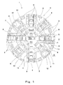
- Fig. 1 is a front view of a tunnel boring machine including one embodiment of an abrasion detecting apparatus according to the present invention.
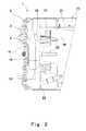
- Fig. 2 is a side view showing a vertical cross section of the tunnel boring machine shown in Fig. 1 .
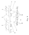
- Fig. 3 is a partially enlarged view of a portion indicated by III in Fig. 1 .
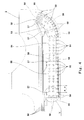
- Fig. 4 is an enlarged cross-sectional view when viewed from a direction indicated by an arrow IV shown in Fig. 1 .
- Fig. 5 is a partially enlarged view of a portion indicated by V shown in Fig. 4 and an explanatory diagram showing the abrasion detecting apparatus according to Embodiment 1.
- Fig. 6 is an enlarged cross-sectional view of an abrasion detection probe shown in Fig. 5 .
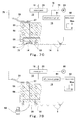
- Fig. 7A is an explanatory diagram for sequentially explaining abrasion detection carried out by the abrasion detecting apparatus.
- Fig. 7B is an explanatory diagram for sequentially explaining the abrasion detection carried out by the abrasion detecting apparatus.
- Fig. 7C is an explanatory diagram for sequentially explaining the abrasion detection carried out by the abrasion detecting apparatus.
- Fig. 7D is an explanatory diagram for sequentially explaining the abrasion detection carried out by the abrasion detecting apparatus.
- Fig. 8 is an explanatory diagram showing the abrasion detection probe of the abrasion detecting apparatus according to Embodiment 2 of the present invention.
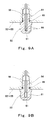
- Fig. 9A is a cross-sectional view showing one example of an ultrasound type detection probe.
- Fig. 9B is a cross-sectional view showing one example of an electric type detection probe.
- a tunnel boring machine including roller cutters configured to excavate a hard ground and tool bits configured to excavate a soft ground.
- a cutter head 2 of a tunnel boring machine 1 of the present embodiment includes a plurality of cutter head frames 3 radially extending from a center portion of the cutter head 2. These cutter head frames 3 and an outer peripheral frame 4 are coupled to one another to form an outer shape of the cutter head 2.
- the cutter head 2 denotes an entire turning head provided at a front portion of the tunnel boring machine 1.
- a plurality of roller cutters 5 are provided at the cutter head frame 3 in a radial direction. These roller cutters 5 are provided at the cutter head 2 by cutter holders 6 each configured to rotatably support the roller cutter 5.
- these roller cutters 5 are arranged in the radial direction, so that respective roller cutters 5 rotate to have different rotation radiuses.
- a center cutter 7 in which a plurality of roller cutters 13 are arranged in parallel with one another is provided at the center portion of the cutter head 2.
- An interval between adjacent roller cutters 5, the number of roller cutters 5, the positions of the cutter head frames 3, the components of the center cutter 7, and the like are determined depending on an excavation diameter, a ground condition (ground) to be excavated, and the like.
- sand intake ports 8 are provided on both sides of each cutter head frame 3. A portion between adjacent sand intake ports 8 is closed by a face plate 9. A slit adjusting plate 11 is provided at the sand intake port 8. The slit adjusting plate 11 adjusts the size of an opening such that the sand, the gravel, and the like taken in a chamber 10 ( Fig. 2 ) behind the cutter head 2 have appropriate sizes so as to be able to be discharged rearward of the tunnel boring machine.
- a plurality of tool bits 12 are arranged in the radial direction at predetermined intervals on a side of the cutter head frame 3 which side faces the sand intake port 8. These tool bits 12 are provided to excavate the soft ground at a position rearward of the roller cutter 5 but forward of the cutter head frame 3 in a case where the soft ground, which is difficult for the roller cutters 5 to excavate, appears during the excavation of the hard ground by the roller cutters 5 ( Fig. 5 ).
- the cutter head 2 is rotatably provided at a front portion of a tunnel boring machine main body 15, and a front end of each roller cutter 5 configured to excavate a ground 14 is a front end of the cutter head 2.
- the cutter head 2 is rotated by a turning frame 18 which is turned by a turning gear 17 which is rotated by a driving machine 16 provided in the tunnel boring machine main body 15.
- the chamber 10 is formed behind the cutter head 2, that is, between the cutter head 2 and a bulkhead 19 provided at a front surface of the tunnel boring machine main body 15, and the sand and the like excavated by the roller cutters 5 of the cutter head 2 are taken through the sand intake port 8 ( Fig. 1 ) into the chamber 10.
- a rotary joint 20 is provided at a turning center of the cutter head 2. Oil, electric power, and the like are supplied through the rotary joint 20 to the cutter head 2 that is a rotating body.
- a slurry feed pipe 21 which feeds slurry into the chamber 10 to apply slurry pressure to the excavated ground is provided at an upper portion of the tunnel boring machine main body 15.
- a plurality of abrasion detection probes 50 are provided at the sand intake port 8 ( Fig. 1 ) of the cutter head 2 of the tunnel boring machine 1. As shown in Fig. 3 , a plurality of abrasion detection probes 50 are provided at predetermined intervals in the radial direction (longitudinal direction) of the sand intake port 8 and are provided at a base portion of the slit adjusting plate 11. Moreover, the abrasion detection probe 50 of the present embodiment is a fluid pressure type abrasion detection probe configured to detect the abrasion from a change in a fluid pressure. The following will explain an example using oil pressure as the fluid pressure.
- a front end of the abrasion detection probe 50 is an abrasion detecting portion 51.
- the abrasion detection probe 50 is attached such that the abrasion detecting portion 51 faces the ground 14.
- a radial interval p between adjacent abrasion detection probes 50 corresponds to an interval between the rotation radiuses of adjacent roller cutters 5 ( Fig. 1 ) of the cutter head 2.
- the abrasion detection probes 50 are respectively provided on rotational trajectories of all the roller cutters 5 in order to detect the abrasion losses of all the roller cutters 5.
- the abrasion detection probes 50 may selectively detect the abrasion of some roller cutters 5 and do not have to be provided for all the roller cutters 5.
- the plurality of abrasion detection probes 50 are separately provided in a plurality of arrangement blocks 52 to 55.
- four arrangement blocks 52 to 55 are arranged in the radial direction.
- the arrangement block 52 is provided for the roller cutter 5 arranged at an outermost position.
- the arrangement block 53 is provided for a plurality of roller cutters 5 arranged at an outer peripheral portion of the cutter head 2.
- the arrangement block 54 is provided for a plurality of roller cutters 5 arranged at an outer peripheral portion of a front surface of the cutter head 2.
- the arrangement block 55 is provided for a plurality of roller cutters 5 arranged at the center portion of the cutter head 2.
- a joint portion 57 is provided at each of the arrangement blocks 52 to 55.
- An oil pressure pipe 56 connected to the rotary joint 20 ( Fig. 2 ) provided at the center portion of the cutter head 2 is connected to the joint portion 57.
- An oil passage 58 is formed inside each of the arrangement blocks 52 to 55 so as to be communicated with the joint portion 57.
- the oil passage 58 is formed to be communicated with an attaching portion 59 of each abrasion detection probe 50. Therefore, by respectively providing the abrasion detection probes 50 at the attaching portions 59, each of the abrasion detection probes 50 is communicated with the oil pressure pipe 56 via the oil passage 58 and the joint portion 57.
- the abrasion detection probes 50 are provided at the slit adjusting plate 11. However, the abrasion detection probes 50 may be incorporated in the cutter head frame 3. Moreover, in the present embodiment, the oil pressure pipes 56 are connected to four arrangement blocks 52 to 55. However, the oil pressure pipes 56 may be individually connected to the abrasion detection probes 50. Further, the number of blocks is not limited to four and may be the other number.
- the abrasion detection probe 50 of an abrasion detecting apparatus 70 according to Embodiment 1 is provided at such a position that the abrasion detection probe 50 can detect that the abrasion loss of the roller cutter 5 has reached a set abrasion loss w.
- the abrasion detection probe 50 of the present embodiment is provided at such a position that the abrasion detecting portion 51 located at the frond end of the abrasion detection probe 50 abrades away when the abrasion loss of the roller cutter 5 has reached the set abrasion loss w (when a colored portion in the drawing has abraded away).
- the oil pressure pipe 56 through which detection oil 75 is supplied to the abrasion detection probe 50 is connected through the rotary joint 20 to an oil pressure pump 60 in the tunnel boring machine main body 15.
- the pressure of the detection oil 75 supplied from the oil pressure pump 60 is detected by an oil pressure gauge 61.
- This pressure is displayed on a display screen 62 of, for example, a monitor that is a display apparatus provided at the tunnel boring machine main body 15.
- the reduction of the pressure of the detection oil 75 is displayed on the display screen 62.
- a warning may be displayed on the display screen 62, or a buzzer sound or the like may be produced.
- the abrasion detection probe 50 is provided at a position which is behind the front end of the cutter head 2, that is, the front end of the roller cutter 5 by a certain distance (set abrasion loss w). With this, before the roller cutter 5 abrades away or is damaged, the abrasion detecting portion 51 of the abrasion detection probe 50 does not contact the ground 14, and the roller cutter 5 excavates the ground 14. When the roller cutter 5 abrades away or is damaged, the ground 14 at this position is not excavated but remains. Therefore, the abrasion detecting portion 51 of the abrasion detection probe 50 at this position contacts the ground 14 to abrade away.
- the detection oil 75 acting on the abrasion detection probe 50 is released, and this decreases the oil pressure of the oil pressure pipe 56.
- the abrasion or damage of the roller cutter 5 at the position where the oil pressure has been decreased can be detected.
- the abrasion detection probe 50 is a plug-shaped member including an internal oil passage 63 whose front end portion is closed.
- the front end portion of the internal oil passage 63 is the abrasion detecting portion 51.
- An attachment external screw portion 64 is formed at a rear end portion of the abrasion detection probe 50, and a sealing portion 65 is formed forward of the external screw portion 64.
- the sealing portion 65 includes an O ring groove 66, and an O ring 67 is provided at the O ring groove 66.
- a flange portion 68 is formed at a front end portion of the sealing portion 65.
- the abrasion detection probe 50 When fixing the abrasion detection probe 50 by screwing the external screw portion 64 into an internal screw portion (not shown) formed at the attaching portion 59 of the arrangement blocks 52 to 55 ( Fig. 4 ), the flange portion 68 contacts the arrangement blocks 52 to 55 to realize the positioning of the abrasion detection probe 50.
- the abrasion detection probe 50 is a replaceable attachment-type device.
- the abrasion detection by the abrasion detecting apparatus 70 will be explained below based on Figs. 7A to 7D . The following will be explained based on the directions shown in Fig. 4 (the front end is downward).
- the cutter head 2 excavates while rotating, so that a plurality of roller cutters 5 provided at the cutter head 2 rotate at the front surface of the cutter head 2. With this, the hard ground 14 located on the rotational trajectories of the plurality of roller cutters 5 is crushed. Thus, the ground in front of the entire surface of the cutter head 2 can be excavated ( Fig. 7A ).
- the ground 14 located on the rotational trajectory of these roller cutter 5 (the roller cutter 5 located second from left in Fig. 7B ) is not excavated. Therefore, the ground 14 reaches the abrasion detecting portion 51 (front end portion) of the abrasion detection probe 50 provided on the rotational trajectory of the abraded or damaged roller cutter 5, and the abrasion detecting portion 51 of the abrasion detection probe 50 abrades away by the ground 14 due to the turning cutter head 2. After that, this state continues, so that the abrasion detecting portion 51 of the abrasion detection probe 50 abrades away, and the front end portion of the internal oil passage 63 opens ( Fig. 7B ).
- the detection oil 75 in the internal oil passage 63 of the abrasion detection probe 50 leaks from the front end of the abrasion detection probe 50 ( Fig. 7C ).
- the pressure of the oil pressure gauge 61 reduces by the leakage of the detection oil 75, and this reduction of the pressure of the detection oil 75 is displayed on the display screen 62. Therefore, an operator can recognize the abrasion of the roller cutter 5 by confirming the reduction of the oil pressure displayed on the display screen 62.
- the abrasion of the roller cutter 5 is detected by the abrasion of the abrasion detecting portion 51 of the abrasion detection probe 50. Therefore, even in a hostile environment, such as a case where the sand and the gravel exist at the front surface of the cutter head 2 and in the chamber 10, it is possible to detect that the roller cutter 5 has reached the set abrasion loss w, without being inhibited by the sand, the gravel, and the like. In addition, monitoring can be carried out regardless of during the excavation or the stopping. To be specific, the existence of a non-excavated portion due to the abrasion of the cutting edge of the roller cutter 5 is detected by the abrasion of the abrasion detecting portion 51 of the abrasion detection probe 50. Therefore, the existence of the non-excavated portion can be detected regardless of normal abrasion or partial abrasion.
- the abrasion detection probes 50 are separately provided in a plurality of arrangement blocks 52 to 55 as described above, the position of the abraded abrasion detection probe 50 can be confirmed by the block before a replacement operation.
- the abraded roller cutter 5 and the abrasion detection probe 50 having the abraded abrasion detecting portion 51 at the front end are replaced with new ones ( Fig. 7D ).
- the roller cutter 5 and the abrasion detection probe 50 are replaced after it is confirmed by the abrasion detection probe 50 that the abrasion loss of the roller cutter 5 has reached the set abrasion loss w. Therefore, the replacement is carried out after the need for the replacement and the position of the replacement are confirmed. Therefore, the replacement can be efficiently carried out.
- the abrasion detecting portion 51 of the abrasion detection probe 50 also abrades away by this abrasion loss, and the detection oil 75 leaks from the front end of the abrasion detection probe 50.
- the detection oil 75 in the oil passage 58 through which the detection oil 75 is acting on the abrasion detection probe 50, is reduced in pressure
- the pressure reduction of the detection oil 75 is detected by the oil pressure gauge 61 configured to measure the pressure of the oil pressure pipe 56, and this pressure reduction can be easily recognized by the display of the pressure shown on the display screen 62. Therefore, by monitoring the pressure of the detection oil 75 displayed on the display screen 62, the operator can easily recognize that the abrasion loss of the roller cutter 5 has reached the set abrasion loss w.
- each of the roller cutters 5 and the cutter holders 6 does not have to include a special mechanism for the abrasion detection, and normal roller cutters and normal cutter holders can be used.
- the abrasion detection probe 50 can be incorporated in a component (the slit adjusting plate 11, the tool bit 12, or the like) mounted on the cutter head 2 or in the frame 3 of the cutter head 2, so that space saving can be realized.
- An abrasion detecting apparatus 71 according to Embodiment 2 shown in Fig. 8 is one example of preventing the cutter head frame 3, which is a component other than the roller cutter 5 of the cutter head 2, from abrading away by the abrasion detection probe 50.
- the same reference numbers are used for the same components as in Embodiment 1, and detailed explanations thereof are omitted.
- each of the abrasion detecting portions 51 of the abrasion detection probes 50 is provided to project from the front surface of the cutter head frame 3 by a predetermined distance v and be located rearward of the front end of the tool bit 12 by a predetermined distance u.
- the abrasion detection probes 50 are provided as above. With this, even if the roller cutter 5 and the tool bit 12 abrade away or are damaged due to any reason, the abrasion detecting portion 51 abrades away before the abrasion of the cutter head frame 3, and this leaks the detection oil 75. Therefore, it is possible to detect that the non-excavated ground 14 is close to the cutter head frame 3. On this account, before the cutter head frame 3 abrades away, the abrasion, the damage, or the like of the roller cutter 5 and the tool bit 12 can be recognized. Therefore, the cutter head frame 3 which is almost irreplaceable among the components of the cutter head 2 can be prevented from abrading away.
- the space saving can be realized by incorporating the abrasion detection probe 50 of the present embodiment in a component (the slit adjusting plate 11, or the like) mounted on the cutter head 2 or in the frame 3 of the cutter head 2.
- Embodiment 1 has explained an example in which the abrasion of the roller cutter 5 is detected
- Embodiment 2 has explained an example in which the abrasion is detected to prevent the cutter head frame 3 from abrading away.
- the abrasion of the tool bit 12 can also be detected by arranging the abrasion detecting portion 51 of the abrasion detection probe 50 such that the abrasion detecting portion 51 is located rearward of the front end of the tool bit 12 by a predetermined distance corresponding to the set abrasion loss.
- the abrasion detection of the tool bit 12 attached rearward of the roller cutter 5 can be carried out in addition to the roller cutter 5, and the detection for preventing the cutter head frame 3 located further rearward of the tool bit 12 from abrading away can also be carried out.
- the abrasion detection probe 50 configured to detect that the abrasion loss of the roller cutter 5 has reached the set abrasion loss as in Embodiment 1, the abrasion detection probe 50 (not shown) configured to detect that the abrasion loss of the tool bit 12 has reached the set abrasion loss, and the abrasion detection probe 50 configured to prevent the cutter head frame 3 from abrading away, the abrasions of the components of the cutter head 2 can be stably detected, and the tunnel boring machine 1 can be stably operated.
- the abrasion detection probe 50 for the abrasion detection is provided at a position (certain distance rearward position) rearward of the front end of the cutter head 2 by a certain distance.
- the non-excavated portion of the ground 14 generated by the abrasion or damage of the component of the cutter head 2 contacts the abrasion detecting portion 51 of the abrasion detection probe 50, and the abrasion detecting portion 51 abrades away.
- the abrasion or damage of the component whose abrasion needs to be detected can be detected.
- each of Embodiments 1 and 2 has explained an example in which the abrasion detection probe 50 is constituted by an oil-pressure type detection probe.
- the abrasion detection probe 50 may be constituted by an electric type detection probe.
- electric wires 80 are provided at the abrasion detecting portion 51 located at the front end portion of the abrasion detection probe 50 ( Fig. 9A ), and a resistance value between these electric wires 80 is measured to be compared with an initial value. With this, the condition of the abrasion of the front end portion of the abrasion detection probe 50 can be detected based on the change in the resistance value.
- the abrasion detection probe 50 is constituted by the electric type detection probe, its configuration is comparatively simple, and its cost is comparatively low.
- the abrasion detection probe 50 may be an ultrasound type detection probe ( Fig. 9B ).
- an ultrasound probe 81 is embedded in the front portion of the abrasion detection probe 50, and the thickness of the abrasion detecting portion 51 located at the front end portion of the abrasion detection probe 50 is obtained by a signal of the ultrasound probe 81 based on a sound wave propagation time.
- the abrasion loss can be detected by the change in the thickness.
- the abrasion detection probe 50 is constituted by the ultrasound type detection probe, the change in the abrasion loss can be continuously measured.
- various mechanisms such as an electric type, an ultrasound type, or an oil-pressure type, can be adopted as a mechanism of the abrasion detection probe 50 configured to detect the abrasion. Which one is adopted may be determined depending on the condition of the ground, the use condition, and the like.
- the abrasion (regardless of normal abrasion or partial abrasion) of the component of the cutter head 2 of the tunnel boring machine 1 can be monitored and detected by the abrasion detection probe 50 regardless of during the excavation or the stopping. Therefore, in the tunnel boring machine 1 configured to excavate the hard ground, the roller cutter 5 and the like which have heavily abraded away can be appropriately replaced with new ones, so that the excavation of the tunnel boring machine 1 can proceed as planned.
- the detection oil 75 is supplied through one oil pressure pipe 56 to each of the arrangement blocks 52 to 55 in each of which a plurality of abrasion detection probes 50 are provided. Therefore, the condition of the abrasion of the roller cutter 5 can be detected by the arrangement blocks 52 to 55.
- the oil pressure pipes 56 may be respectively connected to the abrasion detection probes 50, and each abrasion detection probe 50 may detect the abrasion.
- a plurality of abrasion detection probes 50 may be provided on the rotational trajectories of a plurality of components of the cutter head 2, such as the rotational trajectories of the roller cutters 5 located at positions where the abrasion tends to occur.
- the positions of the abrasion detection probes 50, the number of abrasion detection probes 50, and the like are not limited to those in the above embodiments.
- the abrasion detection probes 50 configured to detect the set abrasion loss of the roller cutter 5 explained in Embodiment 1, the abrasion detection probes 50 configured to detect the set abrasion loss of the tool bit 12, and the abrasion detection probes 50 configured to prevent the cutter head frame 3 explained in Embodiment 2 from abrading away may be provided separately or in combination.
Landscapes
- Engineering & Computer Science (AREA)
- Mining & Mineral Resources (AREA)
- Life Sciences & Earth Sciences (AREA)
- Geology (AREA)
- Environmental & Geological Engineering (AREA)
- General Life Sciences & Earth Sciences (AREA)
- Geochemistry & Mineralogy (AREA)
- Mechanical Engineering (AREA)
- Physics & Mathematics (AREA)
- Fluid Mechanics (AREA)
- Excavating Of Shafts Or Tunnels (AREA)
Applications Claiming Priority (1)
| Application Number | Priority Date | Filing Date | Title |
|---|---|---|---|
| JP2009181843A JP5400522B2 (ja) | 2009-08-04 | 2009-08-04 | カッタヘッドにおける構成物の摩耗検知装置とそれを備えたトンネル掘削機 |
Publications (3)
| Publication Number | Publication Date |
|---|---|
| EP2295705A2 true EP2295705A2 (de) | 2011-03-16 |
| EP2295705A3 EP2295705A3 (de) | 2016-06-15 |
| EP2295705B1 EP2295705B1 (de) | 2017-12-20 |
Family
ID=42671920
Family Applications (1)
| Application Number | Title | Priority Date | Filing Date |
|---|---|---|---|
| EP10171397.2A Active EP2295705B1 (de) | 2009-08-04 | 2010-07-30 | Abreibungserkennungsvorrichtung zur Erkennung von Abreibung bei Schneidkopfkomponenten sowie Tunnelbohrmaschine mit der Abreibungserkennungsvorrichtung |
Country Status (3)
| Country | Link |
|---|---|
| US (1) | US8789890B2 (de) |
| EP (1) | EP2295705B1 (de) |
| JP (1) | JP5400522B2 (de) |
Cited By (16)
| Publication number | Priority date | Publication date | Assignee | Title |
|---|---|---|---|---|
| CN104182620A (zh) * | 2014-08-07 | 2014-12-03 | 华北电力大学 | 用寿命系数对盘形滚刀磨损量进行预测的方法 |
| CN105673032A (zh) * | 2015-12-31 | 2016-06-15 | 李会修 | 圆角梯形顶管掘进机 |
| CN105804646A (zh) * | 2016-04-23 | 2016-07-27 | 刘兰花 | 一种锁扣x桩成桩机 |
| CN105804645A (zh) * | 2016-04-23 | 2016-07-27 | 刘兰花 | 一种接合桩制造装置 |
| CN105804647A (zh) * | 2016-04-23 | 2016-07-27 | 刘兰花 | 咬合丁字桩制造设备 |
| CN105821857A (zh) * | 2016-04-23 | 2016-08-03 | 刘兰花 | 双端凸矩形钻搅机 |
| CN105821858A (zh) * | 2016-04-23 | 2016-08-03 | 刘兰花 | 双端凹矩形桩机 |
| CN105821860A (zh) * | 2016-04-23 | 2016-08-03 | 刘兰花 | 扣合十字桩成桩机 |
| CN105821855A (zh) * | 2016-04-23 | 2016-08-03 | 刘兰花 | 一种扣合桩制造装置 |
| CN105862750A (zh) * | 2016-04-23 | 2016-08-17 | 宗福海 | 一种锁扣桩制造组合 |
| CN105862808A (zh) * | 2016-04-23 | 2016-08-17 | 刘兰花 | 咬合十字桩成桩机 |
| CN105887828A (zh) * | 2016-04-23 | 2016-08-24 | 宗福海 | 一种插扣桩制造组合 |
| CN105908713A (zh) * | 2016-04-23 | 2016-08-31 | 刘兰花 | 双端凹矩形搅拌钻机 |
| CN108266193A (zh) * | 2018-03-12 | 2018-07-10 | 中铁十二局集团有限公司 | Ⅳ、ⅴ级软弱围岩全断面隧道的施工方法 |
| CN108680350A (zh) * | 2018-06-29 | 2018-10-19 | 中铁工程装备集团有限公司 | 一种多功能铰接密封试验台 |
| CN110333059A (zh) * | 2019-07-26 | 2019-10-15 | 中南大学 | 一种基于磨损检测的盾构/tbm滚刀转动状态以及弦磨在线检测方法 |
Families Citing this family (128)
| Publication number | Priority date | Publication date | Assignee | Title |
|---|---|---|---|---|
| CN101936169B (zh) * | 2010-08-24 | 2011-12-07 | 中铁隧道装备制造有限公司 | 软岩盾构机中具有小范围变径功能的切削装置 |
| CN102841030B (zh) * | 2011-06-22 | 2015-06-10 | 中铁隧道集团有限公司 | 用于隧道掘进机刀具破岩机理模态研究的试验平台 |
| JP5930765B2 (ja) * | 2012-02-23 | 2016-06-08 | 日立造船株式会社 | ローラビット磨耗検出装置 |
| US9140123B2 (en) | 2012-04-06 | 2015-09-22 | Caterpillar Inc. | Cutting head tool for tunnel boring machine |
| US9010872B2 (en) | 2012-06-25 | 2015-04-21 | The Robbins Company | Tunnel boring machine with cutterhead support assembly supporting a variable number of drive systems |
| FR3000799B1 (fr) * | 2013-01-09 | 2015-01-30 | Nfm Tech | Ensemble electromecanique equipe d'au moins un organe rotatif et d'un systeme de mesure de l'usure du ou de chaque organe rotatif |
| JP6013272B2 (ja) * | 2013-05-21 | 2016-10-25 | 三井住友建設株式会社 | シールド掘進機 |
| GB2516450A (en) * | 2013-07-22 | 2015-01-28 | Schlumberger Holdings | Instrumented rotary tools with attached cutters |
| CN103954517B (zh) * | 2013-10-24 | 2017-05-17 | 中国煤炭科工集团太原研究院有限公司 | 截齿摩擦磨损试验装置 |
| CN103969139B (zh) * | 2014-04-30 | 2016-06-22 | 大连理工大学 | 一种掘进机在线滚刀磨损检测方法 |
| CN104062197B (zh) * | 2014-07-14 | 2016-05-25 | 中南大学 | 一种硬岩滚刀磨损特性测试装置 |
| CN104792369A (zh) * | 2015-04-30 | 2015-07-22 | 中铁工程装备集团有限公司 | 一种盾构滚刀转速和磨损的无线检测装置 |
| US9464487B1 (en) * | 2015-07-22 | 2016-10-11 | William Harrison Zurn | Drill bit and cylinder body device, assemblies, systems and methods |
| CN105507918A (zh) * | 2015-12-31 | 2016-04-20 | 卢兴耐 | 方形隧道挖掘机 |
| CN105386772A (zh) * | 2015-12-31 | 2016-03-09 | 卢兴耐 | 拱门形隧道挖掘机 |
| CN105673031A (zh) * | 2015-12-31 | 2016-06-15 | 李会修 | 拱门形顶管掘进机 |
| CN105626091A (zh) * | 2015-12-31 | 2016-06-01 | 卢兴耐 | 拱门形顶管掘进机 |
| CN105422117A (zh) * | 2015-12-31 | 2016-03-23 | 卢兴耐 | 圆角三角形隧道挖掘机 |
| CN105604562A (zh) * | 2015-12-31 | 2016-05-25 | 卢兴耐 | 平行四边形隧道挖掘机 |
| CN105422121A (zh) * | 2015-12-31 | 2016-03-23 | 卢兴耐 | 三角形隧道挖掘机 |
| CN105862800A (zh) * | 2016-04-23 | 2016-08-17 | 刘兰花 | 扣合丁字桩制造设备 |
| CN105735291A (zh) * | 2016-04-23 | 2016-07-06 | 刘兰花 | 接合十字桩成桩机 |
| CN105887821A (zh) * | 2016-04-23 | 2016-08-24 | 宗福海 | 插合人字桩制造装置 |
| CN105756042A (zh) * | 2016-04-23 | 2016-07-13 | 宗福海 | 圆弧插扣t形桩制造设备 |
| CN105862749A (zh) * | 2016-04-23 | 2016-08-17 | 宗福海 | 一种圆弧插合丁字桩 |
| CN105821839A (zh) * | 2016-04-23 | 2016-08-03 | 宗福海 | Y形锁口桩制造机具 |
| CN105735294A (zh) * | 2016-04-23 | 2016-07-06 | 刘兰花 | 等宽桩与t桩插扣连接设施 |
| CN105735288A (zh) * | 2016-04-23 | 2016-07-06 | 宗福海 | 一种圆弧扣合丁字桩 |
| CN105714816A (zh) * | 2016-04-23 | 2016-06-29 | 宗福海 | 一种接合十字桩 |
| CN105821842A (zh) * | 2016-04-23 | 2016-08-03 | 宗福海 | 一种插合十字桩 |
| CN105862796A (zh) * | 2016-04-23 | 2016-08-17 | 刘兰花 | 一种插合v形桩制造设备 |
| CN105862752A (zh) * | 2016-04-23 | 2016-08-17 | 宗福海 | 圆弧锁扣梅花桩成桩设施 |
| CN105862814A (zh) * | 2016-04-23 | 2016-08-17 | 刘兰花 | 等宽桩与t桩插口连接设施 |
| CN105862813A (zh) * | 2016-04-23 | 2016-08-17 | 刘兰花 | 等宽桩与十字桩插口连接设施 |
| CN105735287A (zh) * | 2016-04-23 | 2016-07-06 | 宗福海 | Y形插扣桩制造机具 |
| CN105887822A (zh) * | 2016-04-23 | 2016-08-24 | 宗福海 | 圆弧插合l形桩制造装置 |
| CN105862745A (zh) * | 2016-04-23 | 2016-08-17 | 宗福海 | 梅花形插合桩制造装置 |
| CN105862811A (zh) * | 2016-04-23 | 2016-08-17 | 刘兰花 | 矩形桩与h桩锁扣设备 |
| CN105735286A (zh) * | 2016-04-23 | 2016-07-06 | 宗福海 | 凹圆弧插口搅拌桩机 |
| CN105862739A (zh) * | 2016-04-23 | 2016-08-17 | 宗福海 | 插扣l形桩制造装置 |
| CN105862793A (zh) * | 2016-04-23 | 2016-08-17 | 刘兰花 | 一种锁接v形桩制造设备 |
| CN105735297A (zh) * | 2016-04-23 | 2016-07-06 | 刘兰花 | 等宽桩与h桩咬合装置 |
| CN105735295A (zh) * | 2016-04-23 | 2016-07-06 | 刘兰花 | 等厚梯形头桩与π桩咬合装置 |
| CN105821837A (zh) * | 2016-04-23 | 2016-08-03 | 宗福海 | 圆弧插合t形桩制造设备 |
| CN105887820A (zh) * | 2016-04-23 | 2016-08-24 | 宗福海 | 圆弧插扣人字桩制造设备 |
| CN105862744A (zh) * | 2016-04-23 | 2016-08-17 | 宗福海 | 凸圆弧插扣搅拌桩机 |
| CN105862792A (zh) * | 2016-04-23 | 2016-08-17 | 刘兰花 | 一种插合桩制造装置 |
| CN105862794A (zh) * | 2016-04-23 | 2016-08-17 | 刘兰花 | 一种锁扣v形桩制造设备 |
| CN105735289A (zh) * | 2016-04-23 | 2016-07-06 | 宗福海 | 圆弧插扣梅花桩成桩设施 |
| CN105887823A (zh) * | 2016-04-23 | 2016-08-24 | 宗福海 | 圆弧接口桩墙制造设备 |
| CN105862804A (zh) * | 2016-04-23 | 2016-08-17 | 刘兰花 | 矩形插合连接桩墙 |
| CN105887834A (zh) * | 2016-04-23 | 2016-08-24 | 刘兰花 | 等厚梯形头桩与π桩扣合装置 |
| CN105862798A (zh) * | 2016-04-23 | 2016-08-17 | 刘兰花 | 一种插扣x桩成桩机 |
| CN105862741A (zh) * | 2016-04-23 | 2016-08-17 | 宗福海 | 圆弧锁扣十字桩制造设备 |
| CN105887827A (zh) * | 2016-04-23 | 2016-08-24 | 宗福海 | 一种圆弧接口丁字桩 |
| CN105862810A (zh) * | 2016-04-23 | 2016-08-17 | 刘兰花 | 矩形桩与h桩锁口设备 |
| CN105862748A (zh) * | 2016-04-23 | 2016-08-17 | 宗福海 | 一种圆弧接合丁字桩 |
| CN105821838A (zh) * | 2016-04-23 | 2016-08-03 | 宗福海 | 圆弧锁扣t形桩制造设备 |
| CN105862795A (zh) * | 2016-04-23 | 2016-08-17 | 刘兰花 | 一种插扣v形桩制造设备 |
| CN105862754A (zh) * | 2016-04-23 | 2016-08-17 | 宗福海 | 梯形锁扣搅拌桩机 |
| CN105862790A (zh) * | 2016-04-23 | 2016-08-17 | 刘兰花 | 插合丁字桩制造设备 |
| CN105862812A (zh) * | 2016-04-23 | 2016-08-17 | 刘兰花 | 矩形桩与h桩插口设备 |
| CN105862751A (zh) * | 2016-04-23 | 2016-08-17 | 宗福海 | 圆弧插合梅花桩成桩设施 |
| CN105862740A (zh) * | 2016-04-23 | 2016-08-17 | 宗福海 | 圆弧插接l形桩制造装置 |
| CN105862753A (zh) * | 2016-04-23 | 2016-08-17 | 宗福海 | 圆弧插接梅花桩成桩设施 |
| CN105862803A (zh) * | 2016-04-23 | 2016-08-17 | 刘兰花 | 矩形锁扣连接桩墙 |
| CN105862791A (zh) * | 2016-04-23 | 2016-08-17 | 刘兰花 | 一种咬合桩制造装置 |
| CN105862797A (zh) * | 2016-04-23 | 2016-08-17 | 刘兰花 | 一种锁接x桩成桩机 |
| CN105821863A (zh) * | 2016-04-23 | 2016-08-03 | 刘兰花 | 等宽桩与t桩锁扣装置 |
| CN105862801A (zh) * | 2016-04-23 | 2016-08-17 | 刘兰花 | 矩形咬合连接桩墙 |
| CN105862802A (zh) * | 2016-04-23 | 2016-08-17 | 刘兰花 | 矩形插口连接桩墙 |
| CN105756041A (zh) * | 2016-04-23 | 2016-07-13 | 宗福海 | 插接人字桩制造装置 |
| CN105804068A (zh) * | 2016-04-23 | 2016-07-27 | 刘兰花 | 等宽桩与h桩插合装置 |
| CN105887824A (zh) * | 2016-04-23 | 2016-08-24 | 宗福海 | 凹圆弧接口搅拌桩机 |
| CN105862805A (zh) * | 2016-04-23 | 2016-08-17 | 刘兰花 | 双端凸矩形成桩机 |
| CN105735290A (zh) * | 2016-04-23 | 2016-07-06 | 刘兰花 | 一种插接x桩成桩机 |
| CN105887836A (zh) * | 2016-04-23 | 2016-08-24 | 刘兰花 | 等宽桩与h桩扣合装置 |
| CN105862742A (zh) * | 2016-04-23 | 2016-08-17 | 宗福海 | 接口十字桩制造设备 |
| CN105862755A (zh) * | 2016-04-23 | 2016-08-17 | 宗福海 | 圆弧锁扣搅拌桩机 |
| CN105862746A (zh) * | 2016-04-23 | 2016-08-17 | 宗福海 | 梅花形锁口桩制造装置 |
| CN105821843A (zh) * | 2016-04-23 | 2016-08-03 | 宗福海 | V形锁口搅拌桩机 |
| CN105862743A (zh) * | 2016-04-23 | 2016-08-17 | 宗福海 | 圆弧锁扣桩墙制造设备 |
| CN105735282A (zh) * | 2016-04-23 | 2016-07-06 | 宗福海 | 锁口十字桩制造设备 |
| CN105887833A (zh) * | 2016-04-23 | 2016-08-24 | 刘兰花 | 等宽桩与十字桩插扣连接设施 |
| CN105821862A (zh) * | 2016-04-23 | 2016-08-03 | 刘兰花 | 等宽桩与十字桩锁口连接设施 |
| CN105735283A (zh) * | 2016-04-23 | 2016-07-06 | 宗福海 | 圆弧插扣十字桩制造设备 |
| CN105735293A (zh) * | 2016-04-23 | 2016-07-06 | 刘兰花 | 等宽桩与t桩锁口连接设施 |
| CN105908709A (zh) * | 2016-04-23 | 2016-08-31 | 宗福海 | 圆弧插接t形桩制造设备 |
| CN105862809A (zh) * | 2016-04-23 | 2016-08-17 | 刘兰花 | 插合十字桩成桩机 |
| CN105887825A (zh) * | 2016-04-23 | 2016-08-24 | 宗福海 | Y形插口桩制造机具 |
| CN105735284A (zh) * | 2016-04-23 | 2016-07-06 | 宗福海 | 圆弧锁口桩墙制造设备 |
| CN105862738A (zh) * | 2016-04-23 | 2016-08-17 | 宗福海 | 锁扣l形桩制造装置 |
| CN105821861A (zh) * | 2016-04-23 | 2016-08-03 | 刘兰花 | 矩形桩与h桩插扣设备 |
| CN105862737A (zh) * | 2016-04-23 | 2016-08-17 | 宗福海 | 圆弧锁扣人字桩制造设备 |
| CN105862747A (zh) * | 2016-04-23 | 2016-08-17 | 宗福海 | L型接合桩制造器具 |
| CN105887835A (zh) * | 2016-04-23 | 2016-08-24 | 刘兰花 | 等厚梯形头桩与π桩插合装置 |
| CN105821864A (zh) * | 2016-04-23 | 2016-08-03 | 刘兰花 | 等宽桩与h桩接合装置 |
| CN105735285A (zh) * | 2016-04-23 | 2016-07-06 | 宗福海 | 圆弧插扣桩墙制造设备 |
| JP6654504B2 (ja) * | 2016-05-17 | 2020-02-26 | 株式会社小松製作所 | トンネル掘進機 |
| CN105839630A (zh) * | 2016-05-22 | 2016-08-10 | 刘兰花 | 圆弧插扣人字桩基础加固设备 |
| CN105804069A (zh) * | 2016-05-22 | 2016-07-27 | 刘兰花 | 圆弧插口十字桩基础加固设备 |
| CN105839631A (zh) * | 2016-05-22 | 2016-08-10 | 刘兰花 | 圆弧锁扣十字桩基础加固设备 |
| CN106088001A (zh) * | 2016-06-15 | 2016-11-09 | 郇博文 | 凹矩形钻机 |
| CN105970931A (zh) * | 2016-06-15 | 2016-09-28 | 郇博文 | 凹圆钻机 |
| CN106088007A (zh) * | 2016-06-15 | 2016-11-09 | 郇博文 | 凹v形钻机 |
| CN106088002A (zh) * | 2016-06-15 | 2016-11-09 | 郇博文 | 凸梯形钻机 |
| CN106065597A (zh) * | 2016-06-15 | 2016-11-02 | 郇博文 | 凸矩形钻机 |
| KR102623549B1 (ko) | 2016-12-07 | 2024-01-10 | 삼성전자주식회사 | 프로브 카드 및 이를 포함하는 테스트 장치 |
| JP7067735B2 (ja) * | 2017-12-06 | 2022-05-16 | 関西電力株式会社 | 掘削パイプ、掘削パイプの製造方法及び地盤の掘削方法 |
| CN108387473B (zh) * | 2018-02-02 | 2020-09-11 | 中铁隧道局集团有限公司 | 一种掘进设备刀具在软土环境下的磨损试验及预测方法 |
| CN109443969B (zh) * | 2018-10-25 | 2023-09-22 | 西南交通大学 | 一种用于盾构刀盘刀具磨耗特性测试试验装置及方法 |
| CN109281680B (zh) * | 2018-11-13 | 2023-08-15 | 吉林大学 | 具有超声波振动作用的盾构滚刀及滚刀破岩方法 |
| CN109405708B (zh) * | 2018-12-28 | 2023-12-15 | 中国矿业大学(北京) | 盾构机刀盘、刀具磨损测量旋转尺、测量系统及测量方法 |
| CN109973108B (zh) * | 2019-03-17 | 2024-01-12 | 天津大学 | 一种滚刀径向位置可调的tbm刀盘 |
| CN110017147A (zh) * | 2019-05-09 | 2019-07-16 | 中国电建集团铁路建设有限公司 | 一种盾构刀具磨损实时监测系统及监测方法 |
| CN111220493B (zh) | 2019-09-06 | 2021-02-23 | 山东大学 | Tbm搭载式围岩耐磨性测试系统与方法 |
| CN110863833B (zh) * | 2019-11-22 | 2020-12-22 | 中铁隧道局集团有限公司 | 一种隧道盾构掘进始发端头孤石区盾构机的掘进参数的控制工艺 |
| CN112484661B (zh) * | 2020-11-18 | 2021-09-21 | 大连理工大学 | 一种基于反转形貌法的刀具磨损三维形貌原位检测方法 |
| CN112730134B (zh) * | 2020-12-18 | 2023-10-13 | 中铁山河工程装备股份有限公司 | 一种破岩刀具材料-密实核物质对磨试验方法 |
| CN112730133B (zh) * | 2020-12-18 | 2023-03-21 | 湘潭大学 | 一种破岩刀具材料-密实核物质对磨试验装置 |
| CN112901159B (zh) * | 2021-01-29 | 2022-01-11 | 中国矿业大学 | 一种矿井掘进机器人环境监测装置及方法 |
| JP7613689B2 (ja) * | 2021-02-05 | 2025-01-15 | 株式会社大林組 | トンネル掘削機 |
| DE102021110855A1 (de) * | 2021-04-28 | 2022-11-03 | Herrenknecht Aktiengesellschaft | Schneidrad für eine Tunnelvortriebsmaschine |
| CN113622927A (zh) * | 2021-08-17 | 2021-11-09 | 盾构及掘进技术国家重点实验室 | 一种具备载荷监测功能的快速换刀刀座结构 |
| CN114776646B (zh) * | 2022-04-27 | 2024-09-20 | 中铁工程装备集团有限公司 | 一种具备磨损检测功能的tbm滚刀自动夹持装置 |
| CN116734780B (zh) * | 2023-08-14 | 2023-11-10 | 中铁五局集团电务工程有限责任公司 | 硬岩隧道tbm滚刀磨损检测装置 |
| CN120467430B (zh) * | 2025-05-20 | 2025-12-02 | 中铁十九局集团第一工程有限公司 | 一种用于盾构机滚刀磨损识别与掌子面监控的视觉装置 |
| CN120326456B (zh) * | 2025-06-18 | 2025-09-12 | 河北软件职业技术学院 | 一种小型管道巡检打磨装置 |
Citations (4)
| Publication number | Priority date | Publication date | Assignee | Title |
|---|---|---|---|---|
| JPH0514299U (ja) | 1991-08-09 | 1993-02-23 | 株式会社小松製作所 | デイスクカツタの摩耗検出装置 |
| JPH06117188A (ja) | 1992-10-09 | 1994-04-26 | Ishikawajima Harima Heavy Ind Co Ltd | ローラビットの摩耗検知装置 |
| JPH0663423B2 (ja) | 1986-05-20 | 1994-08-22 | 石川島播磨重工業株式会社 | 密閉形シ−ルド掘進機の障害物検知装置 |
| JP2003074295A (ja) | 2001-09-04 | 2003-03-12 | Kawasaki Heavy Ind Ltd | ローラーカッター摩耗検知装置 |
Family Cites Families (14)
| Publication number | Priority date | Publication date | Assignee | Title |
|---|---|---|---|---|
| US3800278A (en) * | 1972-08-22 | 1974-03-26 | S Jaye | Brake lining wear warning gauge |
| JPH0432565Y2 (de) * | 1986-08-29 | 1992-08-05 | ||
| US4911252A (en) * | 1989-02-22 | 1990-03-27 | Estes Roy D | Rock bit loose cone indicator |
| JP3247628B2 (ja) * | 1997-02-07 | 2002-01-21 | 飛島建設株式会社 | シールド掘進機のカッタビットの摩耗検出装置 |
| US5924499A (en) * | 1997-04-21 | 1999-07-20 | Halliburton Energy Services, Inc. | Acoustic data link and formation property sensor for downhole MWD system |
| JP2000204884A (ja) * | 1999-01-12 | 2000-07-25 | Mitsui Eng & Shipbuild Co Ltd | シ―ルド掘進機のカッタビット摩耗検知方法とその検知装置 |
| SG102583A1 (en) * | 1999-07-14 | 2004-03-26 | Mitsubishi Heavy Ind Ltd | Method for replacing cutters of tunnel-excavating machine, method for excavating tunnel, and tunnel-excavating machine |
| JP3460981B2 (ja) * | 2000-07-24 | 2003-10-27 | 西松建設株式会社 | シールド掘進機およびシールド掘進機の掘削可能距離推定方法 |
| US6631772B2 (en) * | 2000-08-21 | 2003-10-14 | Halliburton Energy Services, Inc. | Roller bit rearing wear detection system and method |
| JP4600686B2 (ja) * | 2002-04-18 | 2010-12-15 | 五洋建設株式会社 | シールド掘進機 |
| JP3937401B2 (ja) * | 2002-04-18 | 2007-06-27 | 五洋建設株式会社 | シールド掘進機のカッタビット交換時期検知装置及びシールド掘進機のカッタビットの摩耗検知方法 |
| FR2874959B1 (fr) * | 2004-09-07 | 2007-04-13 | Bouygues Travaux Publics Sa | Procede et dispositifs pour informer en permanence le conducteur d'un tunnelier de la nature du terrain en fond de taille |
| US7404457B2 (en) * | 2006-06-30 | 2008-07-29 | Baker Huges Incorporated | Downhole abrading tools having fusible material and methods of detecting tool wear |
| BRPI0913286B1 (pt) * | 2008-05-30 | 2019-02-19 | The Robbins Company | Equipamento e método para monitoração da eficiência de perfuração de túnel e equipamento de perfuração de túnel |
-
2009
- 2009-08-04 JP JP2009181843A patent/JP5400522B2/ja active Active
-
2010
- 2010-07-27 US US12/844,396 patent/US8789890B2/en active Active
- 2010-07-30 EP EP10171397.2A patent/EP2295705B1/de active Active
Patent Citations (4)
| Publication number | Priority date | Publication date | Assignee | Title |
|---|---|---|---|---|
| JPH0663423B2 (ja) | 1986-05-20 | 1994-08-22 | 石川島播磨重工業株式会社 | 密閉形シ−ルド掘進機の障害物検知装置 |
| JPH0514299U (ja) | 1991-08-09 | 1993-02-23 | 株式会社小松製作所 | デイスクカツタの摩耗検出装置 |
| JPH06117188A (ja) | 1992-10-09 | 1994-04-26 | Ishikawajima Harima Heavy Ind Co Ltd | ローラビットの摩耗検知装置 |
| JP2003074295A (ja) | 2001-09-04 | 2003-03-12 | Kawasaki Heavy Ind Ltd | ローラーカッター摩耗検知装置 |
Cited By (17)
| Publication number | Priority date | Publication date | Assignee | Title |
|---|---|---|---|---|
| CN104182620A (zh) * | 2014-08-07 | 2014-12-03 | 华北电力大学 | 用寿命系数对盘形滚刀磨损量进行预测的方法 |
| CN104182620B (zh) * | 2014-08-07 | 2017-10-10 | 华北电力大学 | 用寿命系数对盘形滚刀磨损量进行预测的方法 |
| CN105673032A (zh) * | 2015-12-31 | 2016-06-15 | 李会修 | 圆角梯形顶管掘进机 |
| CN105821855A (zh) * | 2016-04-23 | 2016-08-03 | 刘兰花 | 一种扣合桩制造装置 |
| CN105862808A (zh) * | 2016-04-23 | 2016-08-17 | 刘兰花 | 咬合十字桩成桩机 |
| CN105821857A (zh) * | 2016-04-23 | 2016-08-03 | 刘兰花 | 双端凸矩形钻搅机 |
| CN105821858A (zh) * | 2016-04-23 | 2016-08-03 | 刘兰花 | 双端凹矩形桩机 |
| CN105821860A (zh) * | 2016-04-23 | 2016-08-03 | 刘兰花 | 扣合十字桩成桩机 |
| CN105804645A (zh) * | 2016-04-23 | 2016-07-27 | 刘兰花 | 一种接合桩制造装置 |
| CN105862750A (zh) * | 2016-04-23 | 2016-08-17 | 宗福海 | 一种锁扣桩制造组合 |
| CN105804647A (zh) * | 2016-04-23 | 2016-07-27 | 刘兰花 | 咬合丁字桩制造设备 |
| CN105887828A (zh) * | 2016-04-23 | 2016-08-24 | 宗福海 | 一种插扣桩制造组合 |
| CN105908713A (zh) * | 2016-04-23 | 2016-08-31 | 刘兰花 | 双端凹矩形搅拌钻机 |
| CN105804646A (zh) * | 2016-04-23 | 2016-07-27 | 刘兰花 | 一种锁扣x桩成桩机 |
| CN108266193A (zh) * | 2018-03-12 | 2018-07-10 | 中铁十二局集团有限公司 | Ⅳ、ⅴ级软弱围岩全断面隧道的施工方法 |
| CN108680350A (zh) * | 2018-06-29 | 2018-10-19 | 中铁工程装备集团有限公司 | 一种多功能铰接密封试验台 |
| CN110333059A (zh) * | 2019-07-26 | 2019-10-15 | 中南大学 | 一种基于磨损检测的盾构/tbm滚刀转动状态以及弦磨在线检测方法 |
Also Published As
| Publication number | Publication date |
|---|---|
| EP2295705B1 (de) | 2017-12-20 |
| EP2295705A3 (de) | 2016-06-15 |
| JP2011032799A (ja) | 2011-02-17 |
| JP5400522B2 (ja) | 2014-01-29 |
| US20110031017A1 (en) | 2011-02-10 |
| US8789890B2 (en) | 2014-07-29 |
Similar Documents
| Publication | Publication Date | Title |
|---|---|---|
| EP2295705B1 (de) | Abreibungserkennungsvorrichtung zur Erkennung von Abreibung bei Schneidkopfkomponenten sowie Tunnelbohrmaschine mit der Abreibungserkennungsvorrichtung | |
| JP3919172B2 (ja) | ディスクローラーカッター及びディスクローラーカッターモニタリングシステム | |
| CN201540105U (zh) | 盾构机刀具磨损监测装置 | |
| JP6266336B2 (ja) | ローラーカッターの摩耗検知装置 | |
| CN103814190B (zh) | 盾构掘进机的挖掘钻头更换装置 | |
| JP6238432B2 (ja) | シールド掘進機のカッタ盤およびそれを備えるシールド掘進機 | |
| JPH1061384A (ja) | トンネル掘削機械のカッタの損耗診断方法 | |
| JP2003082986A (ja) | ローラーカッター摩耗検知装置 | |
| JP3544190B2 (ja) | ローラーカッター摩耗検知装置 | |
| JP2017061828A (ja) | ビット摩耗低減方法およびビット摩耗低減構造 | |
| CN116537809A (zh) | 一种便于监测磨损的分体式滚刀及其填充装置 | |
| JP3588068B2 (ja) | ローラーカッター摩耗検知装置 | |
| JPH11101091A (ja) | トンネル掘削機及び掘削方法 | |
| JP5417232B2 (ja) | 探査システム、シールド機及びシールド機の掘進工法 | |
| JP6777376B2 (ja) | 掘削機および回転ビット | |
| CN222784287U (zh) | 浮动密封试验装置 | |
| JP2925867B2 (ja) | シールド掘進機のローラビット回転検出装置 | |
| JP3477668B2 (ja) | ローラビット回転検出装置 | |
| CN222824996U (zh) | 一种可视化刀盘磨损检测装置 | |
| TW202336340A (zh) | 潛盾挖掘機的刀具盤及具備該刀具盤的潛盾挖掘機 | |
| CN220551117U (zh) | 刀盘装置及盾构机 | |
| CN118704989B (zh) | 一种陡倾层理围岩隧道变形靶向施工方法 | |
| JP7661167B2 (ja) | シールド掘進機の切羽土水圧計測方法及び切羽土水圧計測装置 | |
| KR20260014356A (ko) | 터널 보링 머신 장치의 디스크 커터 홀더 웨지 | |
| CN214366076U (zh) | 一种滚刀及使用该滚刀的切削装置 |
Legal Events
| Date | Code | Title | Description |
|---|---|---|---|
| PUAI | Public reference made under article 153(3) epc to a published international application that has entered the european phase |
Free format text: ORIGINAL CODE: 0009012 |
|
| AK | Designated contracting states |
Kind code of ref document: A2 Designated state(s): AL AT BE BG CH CY CZ DE DK EE ES FI FR GB GR HR HU IE IS IT LI LT LU LV MC MK MT NL NO PL PT RO SE SI SK SM TR |
|
| AX | Request for extension of the european patent |
Extension state: BA ME RS |
|
| PUAL | Search report despatched |
Free format text: ORIGINAL CODE: 0009013 |
|
| AK | Designated contracting states |
Kind code of ref document: A3 Designated state(s): AL AT BE BG CH CY CZ DE DK EE ES FI FR GB GR HR HU IE IS IT LI LT LU LV MC MK MT NL NO PL PT RO SE SI SK SM TR |
|
| AX | Request for extension of the european patent |
Extension state: BA ME RS |
|
| RIC1 | Information provided on ipc code assigned before grant |
Ipc: E21B 12/02 20060101AFI20160510BHEP Ipc: E21D 9/10 20060101ALI20160510BHEP Ipc: E21D 9/00 20060101ALI20160510BHEP |
|
| 17P | Request for examination filed |
Effective date: 20161214 |
|
| RBV | Designated contracting states (corrected) |
Designated state(s): AL AT BE BG CH CY CZ DE DK EE ES FI FR GB GR HR HU IE IS IT LI LT LU LV MC MK MT NL NO PL PT RO SE SI SK SM TR |
|
| GRAP | Despatch of communication of intention to grant a patent |
Free format text: ORIGINAL CODE: EPIDOSNIGR1 |
|
| INTG | Intention to grant announced |
Effective date: 20170628 |
|
| GRAS | Grant fee paid |
Free format text: ORIGINAL CODE: EPIDOSNIGR3 |
|
| GRAA | (expected) grant |
Free format text: ORIGINAL CODE: 0009210 |
|
| RIN1 | Information on inventor provided before grant (corrected) |
Inventor name: SAKAI, YOSHIO Inventor name: KONDO, YASUNORI Inventor name: AIMI, TASO Inventor name: IWATA, HIROYOSHI |
|
| AK | Designated contracting states |
Kind code of ref document: B1 Designated state(s): AL AT BE BG CH CY CZ DE DK EE ES FI FR GB GR HR HU IE IS IT LI LT LU LV MC MK MT NL NO PL PT RO SE SI SK SM TR |
|
| REG | Reference to a national code |
Ref country code: GB Ref legal event code: FG4D |
|
| REG | Reference to a national code |
Ref country code: CH Ref legal event code: EP |
|
| REG | Reference to a national code |
Ref country code: IE Ref legal event code: FG4D |
|
| REG | Reference to a national code |
Ref country code: AT Ref legal event code: REF Ref document number: 956570 Country of ref document: AT Kind code of ref document: T Effective date: 20180115 |
|
| REG | Reference to a national code |
Ref country code: DE Ref legal event code: R096 Ref document number: 602010047443 Country of ref document: DE |
|
| REG | Reference to a national code |
Ref country code: NL Ref legal event code: MP Effective date: 20171220 |
|
| PG25 | Lapsed in a contracting state [announced via postgrant information from national office to epo] |
Ref country code: LT Free format text: LAPSE BECAUSE OF FAILURE TO SUBMIT A TRANSLATION OF THE DESCRIPTION OR TO PAY THE FEE WITHIN THE PRESCRIBED TIME-LIMIT Effective date: 20171220 Ref country code: FI Free format text: LAPSE BECAUSE OF FAILURE TO SUBMIT A TRANSLATION OF THE DESCRIPTION OR TO PAY THE FEE WITHIN THE PRESCRIBED TIME-LIMIT Effective date: 20171220 Ref country code: NO Free format text: LAPSE BECAUSE OF FAILURE TO SUBMIT A TRANSLATION OF THE DESCRIPTION OR TO PAY THE FEE WITHIN THE PRESCRIBED TIME-LIMIT Effective date: 20180320 Ref country code: SE Free format text: LAPSE BECAUSE OF FAILURE TO SUBMIT A TRANSLATION OF THE DESCRIPTION OR TO PAY THE FEE WITHIN THE PRESCRIBED TIME-LIMIT Effective date: 20171220 |
|
| REG | Reference to a national code |
Ref country code: LT Ref legal event code: MG4D |
|
| REG | Reference to a national code |
Ref country code: AT Ref legal event code: MK05 Ref document number: 956570 Country of ref document: AT Kind code of ref document: T Effective date: 20171220 |
|
| PG25 | Lapsed in a contracting state [announced via postgrant information from national office to epo] |
Ref country code: LV Free format text: LAPSE BECAUSE OF FAILURE TO SUBMIT A TRANSLATION OF THE DESCRIPTION OR TO PAY THE FEE WITHIN THE PRESCRIBED TIME-LIMIT Effective date: 20171220 Ref country code: GR Free format text: LAPSE BECAUSE OF FAILURE TO SUBMIT A TRANSLATION OF THE DESCRIPTION OR TO PAY THE FEE WITHIN THE PRESCRIBED TIME-LIMIT Effective date: 20180321 Ref country code: HR Free format text: LAPSE BECAUSE OF FAILURE TO SUBMIT A TRANSLATION OF THE DESCRIPTION OR TO PAY THE FEE WITHIN THE PRESCRIBED TIME-LIMIT Effective date: 20171220 Ref country code: BG Free format text: LAPSE BECAUSE OF FAILURE TO SUBMIT A TRANSLATION OF THE DESCRIPTION OR TO PAY THE FEE WITHIN THE PRESCRIBED TIME-LIMIT Effective date: 20180320 |
|
| PG25 | Lapsed in a contracting state [announced via postgrant information from national office to epo] |
Ref country code: NL Free format text: LAPSE BECAUSE OF FAILURE TO SUBMIT A TRANSLATION OF THE DESCRIPTION OR TO PAY THE FEE WITHIN THE PRESCRIBED TIME-LIMIT Effective date: 20171220 |
|
| PG25 | Lapsed in a contracting state [announced via postgrant information from national office to epo] |
Ref country code: CZ Free format text: LAPSE BECAUSE OF FAILURE TO SUBMIT A TRANSLATION OF THE DESCRIPTION OR TO PAY THE FEE WITHIN THE PRESCRIBED TIME-LIMIT Effective date: 20171220 Ref country code: SK Free format text: LAPSE BECAUSE OF FAILURE TO SUBMIT A TRANSLATION OF THE DESCRIPTION OR TO PAY THE FEE WITHIN THE PRESCRIBED TIME-LIMIT Effective date: 20171220 Ref country code: EE Free format text: LAPSE BECAUSE OF FAILURE TO SUBMIT A TRANSLATION OF THE DESCRIPTION OR TO PAY THE FEE WITHIN THE PRESCRIBED TIME-LIMIT Effective date: 20171220 Ref country code: CY Free format text: LAPSE BECAUSE OF FAILURE TO SUBMIT A TRANSLATION OF THE DESCRIPTION OR TO PAY THE FEE WITHIN THE PRESCRIBED TIME-LIMIT Effective date: 20171220 Ref country code: ES Free format text: LAPSE BECAUSE OF FAILURE TO SUBMIT A TRANSLATION OF THE DESCRIPTION OR TO PAY THE FEE WITHIN THE PRESCRIBED TIME-LIMIT Effective date: 20171220 |
|
| PG25 | Lapsed in a contracting state [announced via postgrant information from national office to epo] |
Ref country code: IT Free format text: LAPSE BECAUSE OF FAILURE TO SUBMIT A TRANSLATION OF THE DESCRIPTION OR TO PAY THE FEE WITHIN THE PRESCRIBED TIME-LIMIT Effective date: 20171220 Ref country code: RO Free format text: LAPSE BECAUSE OF FAILURE TO SUBMIT A TRANSLATION OF THE DESCRIPTION OR TO PAY THE FEE WITHIN THE PRESCRIBED TIME-LIMIT Effective date: 20171220 Ref country code: IS Free format text: LAPSE BECAUSE OF FAILURE TO SUBMIT A TRANSLATION OF THE DESCRIPTION OR TO PAY THE FEE WITHIN THE PRESCRIBED TIME-LIMIT Effective date: 20180420 Ref country code: SM Free format text: LAPSE BECAUSE OF FAILURE TO SUBMIT A TRANSLATION OF THE DESCRIPTION OR TO PAY THE FEE WITHIN THE PRESCRIBED TIME-LIMIT Effective date: 20171220 Ref country code: AT Free format text: LAPSE BECAUSE OF FAILURE TO SUBMIT A TRANSLATION OF THE DESCRIPTION OR TO PAY THE FEE WITHIN THE PRESCRIBED TIME-LIMIT Effective date: 20171220 Ref country code: PL Free format text: LAPSE BECAUSE OF FAILURE TO SUBMIT A TRANSLATION OF THE DESCRIPTION OR TO PAY THE FEE WITHIN THE PRESCRIBED TIME-LIMIT Effective date: 20171220 |
|
| REG | Reference to a national code |
Ref country code: DE Ref legal event code: R097 Ref document number: 602010047443 Country of ref document: DE |
|
| PLBE | No opposition filed within time limit |
Free format text: ORIGINAL CODE: 0009261 |
|
| STAA | Information on the status of an ep patent application or granted ep patent |
Free format text: STATUS: NO OPPOSITION FILED WITHIN TIME LIMIT |
|
| 26N | No opposition filed |
Effective date: 20180921 |
|
| PG25 | Lapsed in a contracting state [announced via postgrant information from national office to epo] |
Ref country code: DK Free format text: LAPSE BECAUSE OF FAILURE TO SUBMIT A TRANSLATION OF THE DESCRIPTION OR TO PAY THE FEE WITHIN THE PRESCRIBED TIME-LIMIT Effective date: 20171220 |
|
| PG25 | Lapsed in a contracting state [announced via postgrant information from national office to epo] |
Ref country code: SI Free format text: LAPSE BECAUSE OF FAILURE TO SUBMIT A TRANSLATION OF THE DESCRIPTION OR TO PAY THE FEE WITHIN THE PRESCRIBED TIME-LIMIT Effective date: 20171220 |
|
| REG | Reference to a national code |
Ref country code: CH Ref legal event code: PL |
|
| PG25 | Lapsed in a contracting state [announced via postgrant information from national office to epo] |
Ref country code: MC Free format text: LAPSE BECAUSE OF FAILURE TO SUBMIT A TRANSLATION OF THE DESCRIPTION OR TO PAY THE FEE WITHIN THE PRESCRIBED TIME-LIMIT Effective date: 20171220 Ref country code: LU Free format text: LAPSE BECAUSE OF NON-PAYMENT OF DUE FEES Effective date: 20180730 |
|
| REG | Reference to a national code |
Ref country code: BE Ref legal event code: MM Effective date: 20180731 |
|
| PG25 | Lapsed in a contracting state [announced via postgrant information from national office to epo] |
Ref country code: FR Free format text: LAPSE BECAUSE OF NON-PAYMENT OF DUE FEES Effective date: 20180731 Ref country code: LI Free format text: LAPSE BECAUSE OF NON-PAYMENT OF DUE FEES Effective date: 20180731 Ref country code: CH Free format text: LAPSE BECAUSE OF NON-PAYMENT OF DUE FEES Effective date: 20180731 |
|
| REG | Reference to a national code |
Ref country code: IE Ref legal event code: MM4A |
|
| PG25 | Lapsed in a contracting state [announced via postgrant information from national office to epo] |
Ref country code: BE Free format text: LAPSE BECAUSE OF NON-PAYMENT OF DUE FEES Effective date: 20180731 |
|
| PG25 | Lapsed in a contracting state [announced via postgrant information from national office to epo] |
Ref country code: IE Free format text: LAPSE BECAUSE OF NON-PAYMENT OF DUE FEES Effective date: 20180730 |
|
| PG25 | Lapsed in a contracting state [announced via postgrant information from national office to epo] |
Ref country code: MT Free format text: LAPSE BECAUSE OF NON-PAYMENT OF DUE FEES Effective date: 20180730 |
|
| PG25 | Lapsed in a contracting state [announced via postgrant information from national office to epo] |
Ref country code: TR Free format text: LAPSE BECAUSE OF FAILURE TO SUBMIT A TRANSLATION OF THE DESCRIPTION OR TO PAY THE FEE WITHIN THE PRESCRIBED TIME-LIMIT Effective date: 20171220 |
|
| PG25 | Lapsed in a contracting state [announced via postgrant information from national office to epo] |
Ref country code: HU Free format text: LAPSE BECAUSE OF FAILURE TO SUBMIT A TRANSLATION OF THE DESCRIPTION OR TO PAY THE FEE WITHIN THE PRESCRIBED TIME-LIMIT; INVALID AB INITIO Effective date: 20100730 Ref country code: PT Free format text: LAPSE BECAUSE OF FAILURE TO SUBMIT A TRANSLATION OF THE DESCRIPTION OR TO PAY THE FEE WITHIN THE PRESCRIBED TIME-LIMIT Effective date: 20171220 |
|
| PG25 | Lapsed in a contracting state [announced via postgrant information from national office to epo] |
Ref country code: MK Free format text: LAPSE BECAUSE OF NON-PAYMENT OF DUE FEES Effective date: 20171220 |
|
| PG25 | Lapsed in a contracting state [announced via postgrant information from national office to epo] |
Ref country code: AL Free format text: LAPSE BECAUSE OF FAILURE TO SUBMIT A TRANSLATION OF THE DESCRIPTION OR TO PAY THE FEE WITHIN THE PRESCRIBED TIME-LIMIT Effective date: 20171220 |
|
| REG | Reference to a national code |
Ref country code: DE Ref legal event code: R081 Ref document number: 602010047443 Country of ref document: DE Owner name: UNDERGROUND INFRASTRUCTURE TECHNOLOGIES CORPOR, JP Free format text: FORMER OWNER: KAWASAKI JUKOGYO KABUSHIKI KAISHA, KOBE-SHI, HYOGO, JP |
|
| PGFP | Annual fee paid to national office [announced via postgrant information from national office to epo] |
Ref country code: GB Payment date: 20250605 Year of fee payment: 16 |
|
| PGFP | Annual fee paid to national office [announced via postgrant information from national office to epo] |
Ref country code: DE Payment date: 20250604 Year of fee payment: 16 |