EP2200909B1 - Deep draw container forming method and device - Google Patents
Deep draw container forming method and device Download PDFInfo
- Publication number
- EP2200909B1 EP2200909B1 EP08830549.5A EP08830549A EP2200909B1 EP 2200909 B1 EP2200909 B1 EP 2200909B1 EP 08830549 A EP08830549 A EP 08830549A EP 2200909 B1 EP2200909 B1 EP 2200909B1
- Authority
- EP
- European Patent Office
- Prior art keywords
- plunger
- film
- forming
- die
- depth
- Prior art date
- Legal status (The legal status is an assumption and is not a legal conclusion. Google has not performed a legal analysis and makes no representation as to the accuracy of the status listed.)
- Active
Links
- 238000000034 method Methods 0.000 title claims description 71
- 230000008569 process Effects 0.000 claims description 49
- 239000011888 foil Substances 0.000 claims description 35
- 239000002552 dosage form Substances 0.000 claims description 25
- 238000004806 packaging method and process Methods 0.000 claims description 21
- 238000004519 manufacturing process Methods 0.000 claims description 16
- 239000002650 laminated plastic Substances 0.000 claims description 8
- 239000004480 active ingredient Substances 0.000 claims description 4
- 239000012530 fluid Substances 0.000 claims description 2
- 239000010410 layer Substances 0.000 description 40
- -1 ampoules Substances 0.000 description 32
- 239000000463 material Substances 0.000 description 30
- 229920003023 plastic Polymers 0.000 description 28
- 239000004033 plastic Substances 0.000 description 28
- 229910052751 metal Inorganic materials 0.000 description 21
- 239000002184 metal Substances 0.000 description 21
- 239000004698 Polyethylene Substances 0.000 description 16
- 229920000573 polyethylene Polymers 0.000 description 16
- 239000004743 Polypropylene Substances 0.000 description 15
- 229920001577 copolymer Polymers 0.000 description 15
- 229920001155 polypropylene Polymers 0.000 description 15
- 238000007493 shaping process Methods 0.000 description 14
- 239000000203 mixture Substances 0.000 description 12
- 229920000642 polymer Polymers 0.000 description 12
- 239000000853 adhesive Substances 0.000 description 11
- 230000001070 adhesive effect Effects 0.000 description 11
- 229910052782 aluminium Inorganic materials 0.000 description 11
- XAGFODPZIPBFFR-UHFFFAOYSA-N aluminium Chemical compound [Al] XAGFODPZIPBFFR-UHFFFAOYSA-N 0.000 description 11
- 229920000139 polyethylene terephthalate Polymers 0.000 description 10
- 239000004952 Polyamide Substances 0.000 description 9
- 229920002647 polyamide Polymers 0.000 description 9
- 239000005020 polyethylene terephthalate Substances 0.000 description 9
- 238000007789 sealing Methods 0.000 description 9
- LYCAIKOWRPUZTN-UHFFFAOYSA-N Ethylene glycol Chemical compound OCCO LYCAIKOWRPUZTN-UHFFFAOYSA-N 0.000 description 7
- BZHJMEDXRYGGRV-UHFFFAOYSA-N Vinyl chloride Chemical compound ClC=C BZHJMEDXRYGGRV-UHFFFAOYSA-N 0.000 description 7
- 229920000728 polyester Polymers 0.000 description 7
- 239000000126 substance Substances 0.000 description 7
- KKEYFWRCBNTPAC-UHFFFAOYSA-N Terephthalic acid Chemical compound OC(=O)C1=CC=C(C(O)=O)C=C1 KKEYFWRCBNTPAC-UHFFFAOYSA-N 0.000 description 6
- NIXOWILDQLNWCW-UHFFFAOYSA-N acrylic acid group Chemical group C(C=C)(=O)O NIXOWILDQLNWCW-UHFFFAOYSA-N 0.000 description 6
- NAQMVNRVTILPCV-UHFFFAOYSA-N hexane-1,6-diamine Chemical compound NCCCCCCN NAQMVNRVTILPCV-UHFFFAOYSA-N 0.000 description 6
- 230000000750 progressive effect Effects 0.000 description 6
- 229920001283 Polyalkylene terephthalate Polymers 0.000 description 5
- 125000002947 alkylene group Chemical group 0.000 description 5
- 125000004432 carbon atom Chemical group C* 0.000 description 5
- 229920001903 high density polyethylene Polymers 0.000 description 5
- 239000004700 high-density polyethylene Substances 0.000 description 5
- 229920001684 low density polyethylene Polymers 0.000 description 5
- 239000004702 low-density polyethylene Substances 0.000 description 5
- 229920001179 medium density polyethylene Polymers 0.000 description 5
- 239000004701 medium-density polyethylene Substances 0.000 description 5
- 239000000825 pharmaceutical preparation Substances 0.000 description 5
- 229940127557 pharmaceutical product Drugs 0.000 description 5
- 239000002985 plastic film Substances 0.000 description 5
- 229920006255 plastic film Polymers 0.000 description 5
- 239000002253 acid Substances 0.000 description 4
- 239000011248 coating agent Substances 0.000 description 4
- 238000000576 coating method Methods 0.000 description 4
- 230000032798 delamination Effects 0.000 description 4
- 229910003460 diamond Inorganic materials 0.000 description 4
- 239000010432 diamond Substances 0.000 description 4
- 229920006242 ethylene acrylic acid copolymer Polymers 0.000 description 4
- 150000002739 metals Chemical class 0.000 description 4
- 229920000098 polyolefin Polymers 0.000 description 4
- 229920006324 polyoxymethylene Polymers 0.000 description 4
- 229920000915 polyvinyl chloride Polymers 0.000 description 4
- 229920001169 thermoplastic Polymers 0.000 description 4
- 239000004416 thermosoftening plastic Substances 0.000 description 4
- 230000004888 barrier function Effects 0.000 description 3
- 230000008901 benefit Effects 0.000 description 3
- 230000003247 decreasing effect Effects 0.000 description 3
- 230000007613 environmental effect Effects 0.000 description 3
- 238000007373 indentation Methods 0.000 description 3
- 229920000092 linear low density polyethylene Polymers 0.000 description 3
- 239000004707 linear low-density polyethylene Substances 0.000 description 3
- 239000007788 liquid Substances 0.000 description 3
- 239000007921 spray Substances 0.000 description 3
- SMZOUWXMTYCWNB-UHFFFAOYSA-N 2-(2-methoxy-5-methylphenyl)ethanamine Chemical compound COC1=CC=C(C)C=C1CCN SMZOUWXMTYCWNB-UHFFFAOYSA-N 0.000 description 2
- NLHHRLWOUZZQLW-UHFFFAOYSA-N Acrylonitrile Chemical compound C=CC#N NLHHRLWOUZZQLW-UHFFFAOYSA-N 0.000 description 2
- 229910052582 BN Inorganic materials 0.000 description 2
- PZNSFCLAULLKQX-UHFFFAOYSA-N Boron nitride Chemical compound N#B PZNSFCLAULLKQX-UHFFFAOYSA-N 0.000 description 2
- OKTJSMMVPCPJKN-UHFFFAOYSA-N Carbon Chemical compound [C] OKTJSMMVPCPJKN-UHFFFAOYSA-N 0.000 description 2
- VYZAMTAEIAYCRO-UHFFFAOYSA-N Chromium Chemical compound [Cr] VYZAMTAEIAYCRO-UHFFFAOYSA-N 0.000 description 2
- XEEYBQQBJWHFJM-UHFFFAOYSA-N Iron Chemical compound [Fe] XEEYBQQBJWHFJM-UHFFFAOYSA-N 0.000 description 2
- PXHVJJICTQNCMI-UHFFFAOYSA-N Nickel Chemical compound [Ni] PXHVJJICTQNCMI-UHFFFAOYSA-N 0.000 description 2
- 239000004677 Nylon Substances 0.000 description 2
- 229920002292 Nylon 6 Polymers 0.000 description 2
- 229930040373 Paraformaldehyde Natural products 0.000 description 2
- 229930182556 Polyacetal Natural products 0.000 description 2
- 239000004793 Polystyrene Substances 0.000 description 2
- 229910000831 Steel Inorganic materials 0.000 description 2
- PPBRXRYQALVLMV-UHFFFAOYSA-N Styrene Chemical compound C=CC1=CC=CC=C1 PPBRXRYQALVLMV-UHFFFAOYSA-N 0.000 description 2
- 239000012790 adhesive layer Substances 0.000 description 2
- WNLRTRBMVRJNCN-UHFFFAOYSA-N adipic acid Chemical compound OC(=O)CCCCC(O)=O WNLRTRBMVRJNCN-UHFFFAOYSA-N 0.000 description 2
- 239000005025 cast polypropylene Substances 0.000 description 2
- 239000000919 ceramic Substances 0.000 description 2
- 238000009826 distribution Methods 0.000 description 2
- 239000003814 drug Substances 0.000 description 2
- 229940079593 drug Drugs 0.000 description 2
- 229920001971 elastomer Polymers 0.000 description 2
- 229920005648 ethylene methacrylic acid copolymer Polymers 0.000 description 2
- 238000007765 extrusion coating Methods 0.000 description 2
- 229910002804 graphite Inorganic materials 0.000 description 2
- 239000010439 graphite Substances 0.000 description 2
- 229910052736 halogen Inorganic materials 0.000 description 2
- 150000002367 halogens Chemical class 0.000 description 2
- WGCNASOHLSPBMP-UHFFFAOYSA-N hydroxyacetaldehyde Natural products OCC=O WGCNASOHLSPBMP-UHFFFAOYSA-N 0.000 description 2
- 238000011065 in-situ storage Methods 0.000 description 2
- 229920000554 ionomer Polymers 0.000 description 2
- 238000012986 modification Methods 0.000 description 2
- 230000004048 modification Effects 0.000 description 2
- CWQXQMHSOZUFJS-UHFFFAOYSA-N molybdenum disulfide Chemical compound S=[Mo]=S CWQXQMHSOZUFJS-UHFFFAOYSA-N 0.000 description 2
- 229920001778 nylon Polymers 0.000 description 2
- 125000004430 oxygen atom Chemical group O* 0.000 description 2
- 239000006187 pill Substances 0.000 description 2
- 229920001707 polybutylene terephthalate Polymers 0.000 description 2
- 229920005644 polyethylene terephthalate glycol copolymer Polymers 0.000 description 2
- 229920002223 polystyrene Polymers 0.000 description 2
- 229920001343 polytetrafluoroethylene Polymers 0.000 description 2
- 239000004810 polytetrafluoroethylene Substances 0.000 description 2
- 239000004800 polyvinyl chloride Substances 0.000 description 2
- 230000005855 radiation Effects 0.000 description 2
- 239000007787 solid Substances 0.000 description 2
- 239000010959 steel Substances 0.000 description 2
- 229920002554 vinyl polymer Polymers 0.000 description 2
- XLYOFNOQVPJJNP-UHFFFAOYSA-N water Substances O XLYOFNOQVPJJNP-UHFFFAOYSA-N 0.000 description 2
- LGXVIGDEPROXKC-UHFFFAOYSA-N 1,1-dichloroethene Chemical compound ClC(Cl)=C LGXVIGDEPROXKC-UHFFFAOYSA-N 0.000 description 1
- VXNZUUAINFGPBY-UHFFFAOYSA-N 1-Butene Chemical compound CCC=C VXNZUUAINFGPBY-UHFFFAOYSA-N 0.000 description 1
- MXAOILAHPVJWBS-UHFFFAOYSA-N 10-(azepan-1-yl)-10-oxodecanamide Chemical compound NC(=O)CCCCCCCCC(=O)N1CCCCCC1 MXAOILAHPVJWBS-UHFFFAOYSA-N 0.000 description 1
- OEPOKWHJYJXUGD-UHFFFAOYSA-N 2-(3-phenylmethoxyphenyl)-1,3-thiazole-4-carbaldehyde Chemical compound O=CC1=CSC(C=2C=C(OCC=3C=CC=CC=3)C=CC=2)=N1 OEPOKWHJYJXUGD-UHFFFAOYSA-N 0.000 description 1
- 229920002799 BoPET Polymers 0.000 description 1
- 229910001369 Brass Inorganic materials 0.000 description 1
- 229910000906 Bronze Inorganic materials 0.000 description 1
- RYGMFSIKBFXOCR-UHFFFAOYSA-N Copper Chemical compound [Cu] RYGMFSIKBFXOCR-UHFFFAOYSA-N 0.000 description 1
- 229920001875 Ebonite Polymers 0.000 description 1
- VGGSQFUCUMXWEO-UHFFFAOYSA-N Ethene Chemical compound C=C VGGSQFUCUMXWEO-UHFFFAOYSA-N 0.000 description 1
- IMROMDMJAWUWLK-UHFFFAOYSA-N Ethenol Chemical compound OC=C IMROMDMJAWUWLK-UHFFFAOYSA-N 0.000 description 1
- 239000005977 Ethylene Substances 0.000 description 1
- CERQOIWHTDAKMF-UHFFFAOYSA-N Methacrylic acid Chemical compound CC(=C)C(O)=O CERQOIWHTDAKMF-UHFFFAOYSA-N 0.000 description 1
- GYCMBHHDWRMZGG-UHFFFAOYSA-N Methylacrylonitrile Chemical compound CC(=C)C#N GYCMBHHDWRMZGG-UHFFFAOYSA-N 0.000 description 1
- 229920000571 Nylon 11 Polymers 0.000 description 1
- 229920000299 Nylon 12 Polymers 0.000 description 1
- BQCADISMDOOEFD-UHFFFAOYSA-N Silver Chemical compound [Ag] BQCADISMDOOEFD-UHFFFAOYSA-N 0.000 description 1
- ATJFFYVFTNAWJD-UHFFFAOYSA-N Tin Chemical compound [Sn] ATJFFYVFTNAWJD-UHFFFAOYSA-N 0.000 description 1
- RTAQQCXQSZGOHL-UHFFFAOYSA-N Titanium Chemical compound [Ti] RTAQQCXQSZGOHL-UHFFFAOYSA-N 0.000 description 1
- XTXRWKRVRITETP-UHFFFAOYSA-N Vinyl acetate Chemical compound CC(=O)OC=C XTXRWKRVRITETP-UHFFFAOYSA-N 0.000 description 1
- HCHKCACWOHOZIP-UHFFFAOYSA-N Zinc Chemical compound [Zn] HCHKCACWOHOZIP-UHFFFAOYSA-N 0.000 description 1
- 150000007513 acids Chemical class 0.000 description 1
- 125000005396 acrylic acid ester group Chemical group 0.000 description 1
- 229960000250 adipic acid Drugs 0.000 description 1
- 150000001299 aldehydes Chemical class 0.000 description 1
- 125000001931 aliphatic group Chemical group 0.000 description 1
- 150000001336 alkenes Chemical class 0.000 description 1
- 229910045601 alloy Inorganic materials 0.000 description 1
- 239000000956 alloy Substances 0.000 description 1
- 150000008064 anhydrides Chemical class 0.000 description 1
- QVGXLLKOCUKJST-UHFFFAOYSA-N atomic oxygen Chemical compound [O] QVGXLLKOCUKJST-UHFFFAOYSA-N 0.000 description 1
- 230000009286 beneficial effect Effects 0.000 description 1
- 229920006378 biaxially oriented polypropylene Polymers 0.000 description 1
- 239000011127 biaxially oriented polypropylene Substances 0.000 description 1
- 230000005540 biological transmission Effects 0.000 description 1
- 230000015572 biosynthetic process Effects 0.000 description 1
- 238000000071 blow moulding Methods 0.000 description 1
- 239000010951 brass Substances 0.000 description 1
- 239000010974 bronze Substances 0.000 description 1
- 230000009172 bursting Effects 0.000 description 1
- 238000003490 calendering Methods 0.000 description 1
- 239000002775 capsule Substances 0.000 description 1
- 150000001732 carboxylic acid derivatives Chemical class 0.000 description 1
- 238000002144 chemical decomposition reaction Methods 0.000 description 1
- 238000006243 chemical reaction Methods 0.000 description 1
- 229910052804 chromium Inorganic materials 0.000 description 1
- 239000011651 chromium Substances 0.000 description 1
- 239000002131 composite material Substances 0.000 description 1
- 150000001875 compounds Chemical class 0.000 description 1
- 229910052802 copper Inorganic materials 0.000 description 1
- 239000010949 copper Substances 0.000 description 1
- KUNSUQLRTQLHQQ-UHFFFAOYSA-N copper tin Chemical compound [Cu].[Sn] KUNSUQLRTQLHQQ-UHFFFAOYSA-N 0.000 description 1
- 125000004122 cyclic group Chemical group 0.000 description 1
- 230000007812 deficiency Effects 0.000 description 1
- 238000000151 deposition Methods 0.000 description 1
- 230000006866 deterioration Effects 0.000 description 1
- 150000001993 dienes Chemical class 0.000 description 1
- 238000004090 dissolution Methods 0.000 description 1
- 239000008298 dragée Substances 0.000 description 1
- 230000000694 effects Effects 0.000 description 1
- 239000000806 elastomer Substances 0.000 description 1
- 150000002148 esters Chemical class 0.000 description 1
- 229940093476 ethylene glycol Drugs 0.000 description 1
- 239000005038 ethylene vinyl acetate Substances 0.000 description 1
- 230000001747 exhibiting effect Effects 0.000 description 1
- 229920002313 fluoropolymer Polymers 0.000 description 1
- 239000004811 fluoropolymer Substances 0.000 description 1
- 238000009472 formulation Methods 0.000 description 1
- 230000005251 gamma ray Effects 0.000 description 1
- 239000007789 gas Substances 0.000 description 1
- 239000011521 glass Substances 0.000 description 1
- PCHJSUWPFVWCPO-UHFFFAOYSA-N gold Chemical compound [Au] PCHJSUWPFVWCPO-UHFFFAOYSA-N 0.000 description 1
- 229910052737 gold Inorganic materials 0.000 description 1
- 239000010931 gold Substances 0.000 description 1
- 229920000578 graft copolymer Polymers 0.000 description 1
- 238000010438 heat treatment Methods 0.000 description 1
- 230000002706 hydrostatic effect Effects 0.000 description 1
- 230000002779 inactivation Effects 0.000 description 1
- 238000010348 incorporation Methods 0.000 description 1
- 229910052742 iron Inorganic materials 0.000 description 1
- QQVIHTHCMHWDBS-UHFFFAOYSA-L isophthalate(2-) Chemical compound [O-]C(=O)C1=CC=CC(C([O-])=O)=C1 QQVIHTHCMHWDBS-UHFFFAOYSA-L 0.000 description 1
- 150000002576 ketones Chemical class 0.000 description 1
- 239000007937 lozenge Substances 0.000 description 1
- FPYJFEHAWHCUMM-UHFFFAOYSA-N maleic anhydride Chemical compound O=C1OC(=O)C=C1 FPYJFEHAWHCUMM-UHFFFAOYSA-N 0.000 description 1
- 238000002844 melting Methods 0.000 description 1
- 230000008018 melting Effects 0.000 description 1
- 125000005395 methacrylic acid group Chemical class 0.000 description 1
- 238000002156 mixing Methods 0.000 description 1
- 238000000465 moulding Methods 0.000 description 1
- ZETYUTMSJWMKNQ-UHFFFAOYSA-N n,n',n'-trimethylhexane-1,6-diamine Chemical compound CNCCCCCCN(C)C ZETYUTMSJWMKNQ-UHFFFAOYSA-N 0.000 description 1
- 229910052759 nickel Inorganic materials 0.000 description 1
- JRZJOMJEPLMPRA-UHFFFAOYSA-N olefin Natural products CCCCCCCC=C JRZJOMJEPLMPRA-UHFFFAOYSA-N 0.000 description 1
- 229910052760 oxygen Inorganic materials 0.000 description 1
- 239000001301 oxygen Substances 0.000 description 1
- 230000035515 penetration Effects 0.000 description 1
- WXZMFSXDPGVJKK-UHFFFAOYSA-N pentaerythritol Chemical compound OCC(CO)(CO)CO WXZMFSXDPGVJKK-UHFFFAOYSA-N 0.000 description 1
- 239000008194 pharmaceutical composition Substances 0.000 description 1
- 239000000546 pharmaceutical excipient Substances 0.000 description 1
- 238000001782 photodegradation Methods 0.000 description 1
- 239000006223 plastic coating Substances 0.000 description 1
- 238000005498 polishing Methods 0.000 description 1
- 229920001200 poly(ethylene-vinyl acetate) Polymers 0.000 description 1
- 229920000058 polyacrylate Polymers 0.000 description 1
- 229920001225 polyester resin Polymers 0.000 description 1
- 239000004645 polyester resin Substances 0.000 description 1
- 229920001195 polyisoprene Polymers 0.000 description 1
- 229920000874 polytetramethylene terephthalate Polymers 0.000 description 1
- 229920002635 polyurethane Polymers 0.000 description 1
- 239000004814 polyurethane Substances 0.000 description 1
- 239000011148 porous material Substances 0.000 description 1
- 229920005653 propylene-ethylene copolymer Polymers 0.000 description 1
- 239000011253 protective coating Substances 0.000 description 1
- 230000009467 reduction Effects 0.000 description 1
- 229920005989 resin Polymers 0.000 description 1
- 239000011347 resin Substances 0.000 description 1
- 239000005060 rubber Substances 0.000 description 1
- 229910052709 silver Inorganic materials 0.000 description 1
- 239000004332 silver Substances 0.000 description 1
- 239000002904 solvent Substances 0.000 description 1
- 239000010935 stainless steel Substances 0.000 description 1
- 229910001220 stainless steel Inorganic materials 0.000 description 1
- 229920006301 statistical copolymer Polymers 0.000 description 1
- 238000003860 storage Methods 0.000 description 1
- 239000000829 suppository Substances 0.000 description 1
- 239000003826 tablet Substances 0.000 description 1
- 229920001897 terpolymer Polymers 0.000 description 1
- BFKJFAAPBSQJPD-UHFFFAOYSA-N tetrafluoroethene Chemical group FC(F)=C(F)F BFKJFAAPBSQJPD-UHFFFAOYSA-N 0.000 description 1
- 238000003856 thermoforming Methods 0.000 description 1
- 239000011135 tin Substances 0.000 description 1
- 229910052718 tin Inorganic materials 0.000 description 1
- 239000010936 titanium Substances 0.000 description 1
- 229910052719 titanium Inorganic materials 0.000 description 1
- 238000012876 topography Methods 0.000 description 1
- 238000007666 vacuum forming Methods 0.000 description 1
- 229940117958 vinyl acetate Drugs 0.000 description 1
- 229920001567 vinyl ester resin Polymers 0.000 description 1
- 125000000391 vinyl group Chemical group [H]C([*])=C([H])[H] 0.000 description 1
- 238000010792 warming Methods 0.000 description 1
- 238000003466 welding Methods 0.000 description 1
- 229910052725 zinc Inorganic materials 0.000 description 1
- 239000011701 zinc Substances 0.000 description 1
Images


Classifications
-
- B—PERFORMING OPERATIONS; TRANSPORTING
- B65—CONVEYING; PACKING; STORING; HANDLING THIN OR FILAMENTARY MATERIAL
- B65B—MACHINES, APPARATUS OR DEVICES FOR, OR METHODS OF, PACKAGING ARTICLES OR MATERIALS; UNPACKING
- B65B47/00—Apparatus or devices for forming pockets or receptacles in or from sheets, blanks, or webs, comprising essentially a die into which the material is pressed or a folding die through which the material is moved
-
- A—HUMAN NECESSITIES
- A61—MEDICAL OR VETERINARY SCIENCE; HYGIENE
- A61J—CONTAINERS SPECIALLY ADAPTED FOR MEDICAL OR PHARMACEUTICAL PURPOSES; DEVICES OR METHODS SPECIALLY ADAPTED FOR BRINGING PHARMACEUTICAL PRODUCTS INTO PARTICULAR PHYSICAL OR ADMINISTERING FORMS; DEVICES FOR ADMINISTERING FOOD OR MEDICINES ORALLY; BABY COMFORTERS; DEVICES FOR RECEIVING SPITTLE
- A61J1/00—Containers specially adapted for medical or pharmaceutical purposes
- A61J1/03—Containers specially adapted for medical or pharmaceutical purposes for pills or tablets
- A61J1/035—Blister-type containers
-
- B—PERFORMING OPERATIONS; TRANSPORTING
- B21—MECHANICAL METAL-WORKING WITHOUT ESSENTIALLY REMOVING MATERIAL; PUNCHING METAL
- B21D—WORKING OR PROCESSING OF SHEET METAL OR METAL TUBES, RODS OR PROFILES WITHOUT ESSENTIALLY REMOVING MATERIAL; PUNCHING METAL
- B21D22/00—Shaping without cutting, by stamping, spinning, or deep-drawing
- B21D22/20—Deep-drawing
- B21D22/206—Deep-drawing articles from a strip in several steps, the articles being coherent with the strip during the operation
-
- B—PERFORMING OPERATIONS; TRANSPORTING
- B29—WORKING OF PLASTICS; WORKING OF SUBSTANCES IN A PLASTIC STATE IN GENERAL
- B29C—SHAPING OR JOINING OF PLASTICS; SHAPING OF MATERIAL IN A PLASTIC STATE, NOT OTHERWISE PROVIDED FOR; AFTER-TREATMENT OF THE SHAPED PRODUCTS, e.g. REPAIRING
- B29C51/00—Shaping by thermoforming, i.e. shaping sheets or sheet like preforms after heating, e.g. shaping sheets in matched moulds or by deep-drawing; Apparatus therefor
- B29C51/14—Shaping by thermoforming, i.e. shaping sheets or sheet like preforms after heating, e.g. shaping sheets in matched moulds or by deep-drawing; Apparatus therefor using multilayered preforms or sheets
-
- B—PERFORMING OPERATIONS; TRANSPORTING
- B29—WORKING OF PLASTICS; WORKING OF SUBSTANCES IN A PLASTIC STATE IN GENERAL
- B29C—SHAPING OR JOINING OF PLASTICS; SHAPING OF MATERIAL IN A PLASTIC STATE, NOT OTHERWISE PROVIDED FOR; AFTER-TREATMENT OF THE SHAPED PRODUCTS, e.g. REPAIRING
- B29C67/00—Shaping techniques not covered by groups B29C39/00 - B29C65/00, B29C70/00 or B29C73/00
- B29C67/0029—Cold deforming of thermoplastics material
-
- B—PERFORMING OPERATIONS; TRANSPORTING
- B65—CONVEYING; PACKING; STORING; HANDLING THIN OR FILAMENTARY MATERIAL
- B65B—MACHINES, APPARATUS OR DEVICES FOR, OR METHODS OF, PACKAGING ARTICLES OR MATERIALS; UNPACKING
- B65B47/00—Apparatus or devices for forming pockets or receptacles in or from sheets, blanks, or webs, comprising essentially a die into which the material is pressed or a folding die through which the material is moved
- B65B47/04—Apparatus or devices for forming pockets or receptacles in or from sheets, blanks, or webs, comprising essentially a die into which the material is pressed or a folding die through which the material is moved by application of mechanical pressure
-
- B—PERFORMING OPERATIONS; TRANSPORTING
- B65—CONVEYING; PACKING; STORING; HANDLING THIN OR FILAMENTARY MATERIAL
- B65D—CONTAINERS FOR STORAGE OR TRANSPORT OF ARTICLES OR MATERIALS, e.g. BAGS, BARRELS, BOTTLES, BOXES, CANS, CARTONS, CRATES, DRUMS, JARS, TANKS, HOPPERS, FORWARDING CONTAINERS; ACCESSORIES, CLOSURES, OR FITTINGS THEREFOR; PACKAGING ELEMENTS; PACKAGES
- B65D75/00—Packages comprising articles or materials partially or wholly enclosed in strips, sheets, blanks, tubes, or webs of flexible sheet material, e.g. in folded wrappers
- B65D75/28—Articles or materials wholly enclosed in composite wrappers, i.e. wrappers formed by associating or interconnecting two or more sheets or blanks
- B65D75/30—Articles or materials enclosed between two opposed sheets or blanks having their margins united, e.g. by pressure-sensitive adhesive, crimping, heat-sealing, or welding
- B65D75/32—Articles or materials enclosed between two opposed sheets or blanks having their margins united, e.g. by pressure-sensitive adhesive, crimping, heat-sealing, or welding one or both sheets or blanks being recessed to accommodate contents
- B65D75/325—Articles or materials enclosed between two opposed sheets or blanks having their margins united, e.g. by pressure-sensitive adhesive, crimping, heat-sealing, or welding one or both sheets or blanks being recessed to accommodate contents one sheet being recessed, and the other being a flat not- rigid sheet, e.g. puncturable or peelable foil
-
- B—PERFORMING OPERATIONS; TRANSPORTING
- B29—WORKING OF PLASTICS; WORKING OF SUBSTANCES IN A PLASTIC STATE IN GENERAL
- B29C—SHAPING OR JOINING OF PLASTICS; SHAPING OF MATERIAL IN A PLASTIC STATE, NOT OTHERWISE PROVIDED FOR; AFTER-TREATMENT OF THE SHAPED PRODUCTS, e.g. REPAIRING
- B29C2791/00—Shaping characteristics in general
- B29C2791/001—Shaping in several steps
-
- B—PERFORMING OPERATIONS; TRANSPORTING
- B29—WORKING OF PLASTICS; WORKING OF SUBSTANCES IN A PLASTIC STATE IN GENERAL
- B29C—SHAPING OR JOINING OF PLASTICS; SHAPING OF MATERIAL IN A PLASTIC STATE, NOT OTHERWISE PROVIDED FOR; AFTER-TREATMENT OF THE SHAPED PRODUCTS, e.g. REPAIRING
- B29C51/00—Shaping by thermoforming, i.e. shaping sheets or sheet like preforms after heating, e.g. shaping sheets in matched moulds or by deep-drawing; Apparatus therefor
- B29C51/08—Deep drawing or matched-mould forming, i.e. using mechanical means only
-
- B—PERFORMING OPERATIONS; TRANSPORTING
- B29—WORKING OF PLASTICS; WORKING OF SUBSTANCES IN A PLASTIC STATE IN GENERAL
- B29L—INDEXING SCHEME ASSOCIATED WITH SUBCLASS B29C, RELATING TO PARTICULAR ARTICLES
- B29L2009/00—Layered products
- B29L2009/003—Layered products comprising a metal layer
-
- B—PERFORMING OPERATIONS; TRANSPORTING
- B29—WORKING OF PLASTICS; WORKING OF SUBSTANCES IN A PLASTIC STATE IN GENERAL
- B29L—INDEXING SCHEME ASSOCIATED WITH SUBCLASS B29C, RELATING TO PARTICULAR ARTICLES
- B29L2031/00—Other particular articles
- B29L2031/712—Containers; Packaging elements or accessories, Packages
- B29L2031/7162—Boxes, cartons, cases
- B29L2031/7164—Blister packages
Definitions
- This disclosure relates to shaped structures or containers and methods of manufacturing shaped structures suitable for use in packaging articles, for example pharmaceutical products.
- this disclosure relates generally to blister packages and methods of manufacturing blister packages.
- Shaped articles such as a shaped structure, shaped packaging, or shaped blister (e.g., blister packs), have been commonly used to package a variety of products, including pharmaceutical dosage forms, where each individual unit-dose of the product may be contained or housed separately from each other and protected from the environment.
- Pharmaceutical dosage forms e.g., pharmaceutical compositions
- pharmaceutical compositions especially those packaged as individual pre-measured doses, present significant packaging challenges, as many such products are susceptible to chemical or photo-degradation, chemical reaction and/or inactivation upon exposure to air, water, light or other environmental factors. Given the frequently considerable cost of such dosage forms, as well as the importance of delivering the intended dose of active ingredient(s) to a patient, losses or deterioration due to such environmental variables must be rigorously protected against.
- Blister packs also sometimes referred to as push through packs, have been used for many years to house individually separated products, including individual doses of pharmaceutical dosage forms.
- blister packs contain an array or series of blisters positioned in a square or rectangular-shaped film.
- Each blister contains the product therein and is covered with a cover layer such as a lidding secured to the film layer at least at the perimeter of the top of each blister.
- This lidding typically seals the blister and protects the contents therein by isolating the contents from the environment outside the blister.
- Any conventional lidding material and techniques well-known to those of skill in the art can be used to seal the formed recess.
- polymeric sheet layers, metallic sheet layers such as foil, and bonding techniques associated therewith such as adhesives and the like can be used.
- Blisters in blister packs may be manufactured by deforming a film layer, which may be accomplished by a number of different techniques known to those of skill in the art. Generally, shaped blisters are made by deep drawing, stretch-drawing or thermoforming of a film. Other blister-forming techniques include blow forming and vacuum forming softened films against a die. Blisters typically are produced in circular, square or rectangular overall cross-sections. Additionally, film layers may be in the form of a laminate including a metal foil coated with a plastic, for example to manufacture shaped articles where a section of the film is forced into a mold defining a recess having substantially similar dimensions to the desired shape of the blister to be created.
- Blister packs can also have the additional function of acting as a mold during the manufacturing process of a product such as a pharmaceutical dosage form.
- the blister pack acts as a mold for forming the product, as well as the containment and packaging for the in situ molded product.
- in situ molded dosage forms can be prepared by depositing a liquid form of a composition directly in a blister and subsequently treating the blister and its contents such that the composition solidifies to form the final dosage form. This technique may be used to prepare freeze-dried or lyophilized dosage forms, for example.
- An example of such a technique is disclosed in Thompson et al., U.S. Pat. No. 5,457,895 .
- An example of a process for forming a blister puch using a first and a second plunger is shown in US6699566 .
- Processes for forming shaped packaging of laminates containing metal foils typically involve shaping tools including a stamp (i.e., a plunger), a die, and a retaining tool.
- a stamp i.e., a plunger
- the laminate is clamped securely between the die and the retaining tool, and the stamp is moved towards the laminate.
- the stamp moves deeper into the openings in the die thereby deforming the laminate.
- the flat laminate is converted into a shaped part exhibiting one or more recesses which are surrounded by an area corresponding to the original flat plane of the laminate. Only that part of the laminate in the region of the die opening can flow or be stretched to form a shaped part.
- Two areas of concern with forming blister packs using methods known in the art are the uniformity of the material thickness after the draw is complete, and fracturing of the material.
- current methods draw the film material in a manner that does not adequately distribute the stresses evenly in the blister, which results in uneven distribution of the material and leads to higher stresses and a greater likelihood of failures.
- the material is more likely to have thin spots that are prone to fractures.
- the present disclosure is directed to processes for manufacturing shaped articles for unit-dose packaging with at least one formed recess.
- One advantage of the processes disclosed herein is that as the film is drawn to form a recess, the resulting stresses on the film are more evenly distributed in the formed recess then in current methods, which reduces the likelihood of thin spots, fractures, and other failures of the formed recesses.
- Current limitations on processes for blister forming do not adequately address the difficulties with complicated blister shapes such as deep blisters or blisters with steep angled/vertical walls. The limitations are compounded when manufacturing deep drawn blisters with a small inner radius and vertical walls.
- the film material is drawn with a plunger(s) that is designed to evenly distribute the stress and the material to a depth that is not based on the final depth of the formed recess, but rather to a depth associated with the first stage of drawing being formed to the final surface area of the formed recess.
- a second stage plunger(s) with complicated features such as a small radius and vertical walls then reshapes the drawn film into the final formed recess while maintaining the surface area formed in the first stage.
- Current methods that form blisters from metal-plastic foils also have complications associated with delamination of the plastic layers from the foil, particularly when the blisters contain fluids.
- the Area Ratio may be calculated as the Formed Surface Area/Beginning Surface Area Within Mold Clamp.
- the film may be selected from suitable materials well known to those of skill in the art, including, for example, a metal-plastic laminate, which may have a plastic layer on one or both sides of the metal foil layer.
- the steps (b) and (c) may both be performed using a warm-forming process, a cold forming process, or a combination of warm-forming and cold-forming steps.
- the shaped article is a shaped blister.
- Certain embodiments of the present disclosure further comprise placing a unit dose of a pharmaceutical dosage form and/or piercers (e.g., internal piercers) in the packaging recess.
- the shaped articles of the present disclosure may be associated with an external piercer.
- the pharmaceutical dosage form may comprise one or more active ingredients, and may be in a solid form, an aqueous form, or a form that is subsequently solidified (e.g., formulations which are lyophilized, freeze-dried, or subjected to solid state dissolution). After the recess is formed, a lid stock such as a metal foil lidding may be sealed onto the shaped article.
- the second plunger may be driven into the primary contour to a depth that is less than the depth of the primary contour (i.e., up to about 100% of the primary contour), and may redistribute, reshape, or stretch the film of the primary contour to a different geometric shape, thereby forming the formed recess.
- the retaining tool is an upper die plate and the die is a lower die plate.
- the upper die plate comprises the first plunger and the second plunger, while the lower die plate comprises a primary forming chamber and a final forming chamber.
- the plunger may comprise a surface or a finish that influences the level of friction between the plunger and the film.
- the first plunger may comprise a high friction forming surface
- the second plunger may comprise a low friction forming surface
- the first (or previous) plunger may have a higher friction forming surface than the second (or subsequent) plunger.
- a "high friction forming surface” is a surface that prevents or impedes the film from slipping or sliding over the surface of the plunger.
- a "low friction forming surface” is a surface that assists or contributes to the film slipping or sliding over the surface of the plunger.
- the plungers may be sequenced such that there is a gradual reduction in the degree of friction between the plungers and the film.
- different topography, geometry, molding, configuration, materials, surface finishes, or combinations thereof may be utilized with the plungers, for example on the end of the plungers, to affect the friction between the plungers and the film.
- the die may have a plurality of spaced die openings, which may comprise sequential forming chambers, including a primary forming chamber and a final forming chamber.
- the die openings may be spaced in a single row, or in multiple rows.
- the forming chambers are aligned with a plurality of plungers, which are used sequentially to create the formed recess.
- the plungers may be lowered sequentially into the same die opening, or sequentially into a series of forming chambers, for example by pushing the film from die to die, e.g., from chamber to chamber, such that the film is advanced after being further formed by a plunger, until it comes to the final forming chamber and plunger and is given its final formed shape.
- the plurality of plungers include at least a first and a second plunger, and may include a third plunger, and additional sequential plungers for creating the formed recess.
- a second or final plunger is used to redistribute, reshape or stretch the primary contour to add geometric features, thereby forming the formed recess.
- the final shape of the formed recess may be accomplished by one or more additional plungers, which add the desired geometric features to the contour and/or stretch it to the final desired area and shape.
- the plunger(s) may be shaped to take into account the grain of the aluminum and produce greater stretch area without rupture of the aluminum layer of the laminate.
- inventions of the present disclosure include devices for manufacturing a shaped article in accordance wiht claim 11.
- a foil lidding is sealed onto the shaped packaging.
- the shaped article is a shaped blister.
- any embodiment discussed in this specification can be implemented with respect to any process, device, or composition of the invention, and vice versa.
- the term "about” as used herein is defined as being close to as understood by one of ordinary skill in the art, and in one non-limiting embodiment the terms are defined to be within 10%, within 5%, within 1%, or within 0.5%.
- the term “substantially” and its variations as used herein are defined as being largely but not necessarily wholly what is specified as understood by one of ordinary skill in the art, and in one non-limiting embodiment substantially refers to ranges within 10%, within 5%, within 1%, or within 0.5%.
- each of the variously stated ranges herein is intended to be continuous so as to include each numerical parameter between the stated minimum and maximum value of each range. It is to be further understood that, while not intending to limit the applicability of the doctrine of equivalents to the scope of the claims, each numerical parameter should at least be construed in a manner consistent with the reported number of significant digits for each numerical parameter and by applying ordinary rounding techniques.
- the words “comprising” (and any form of comprising, such as “comprise” and “comprises”), “having” (and any form of having, such as “have” and “has”), "including” (and any form of including, such as “includes” and “include”) or “containing” (and any form of containing, such as “contains” and “contain”) are inclusive or open-ended and do not exclude additional, unrecited elements or method steps.
- the present disclosure is directed to processes for manufacturing shaped articles such as shaped structures, containers, packaging, or blisters, suitable for unit-dose packaging.
- One purpose of the forming process is to produce a formed recess, such as a blister, suitable for holding pharmaceutical products, foodstuffs, luxury consumables, and technical articles.
- the pharmaceutical products may include but are not limited to medication, ampoules, pills, capsules, tablets, lozenges, dragées, suppositories, fast-dissolving dosage forms (e.g., freeze-dried dosage forms, lyophilized dosage forms), molded devices, and the like, which can then be sealed by the application of a coating such as a lidding over the opening of the formed recess.
- the disclosure is directed to manufacturing blister packages, for example for packaging pharmaceutical products.
- the unit dose is a pharmaceutical product
- the unit dose is typically the amount of a pharmaceutical dosage form administered to a patient in a single dose, and may comprise one or more active ingredients, as well as one or more excipients.
- Unit-dose packaging is the packaging of a unit dose in a non-reusable container.
- the processes disclosed herein are capable of creating shapes and degrees of stretch in the film material that cannot be obtained by methods known in the art.
- the processes of this disclosure involve clamping a film such as a foil laminate and forcing a succession of stamping tools (i.e., plungers) into the film to produce a desired shaped recess (i.e., depression) in film.
- the process for manufacturing the shaped articles generally involves at least one retaining tool, at least one die, and at least two plungers.
- the retaining tool and the die are designed to hold a film between them, with the die having at least one opening, which allows the film layer to be deformed into the desired shape of the formed recess.
- Plungers of various shape, size, number and surface finish may be incorporated into the process.
- a forming process may use a first plunger which exhibits a high degree of friction and a second or subsequent plungers which exhibit progressively higher or lower degrees of friction.
- the film layer may include a variety of different materials, including, but not limited to, thermoplastics, polymers, copolymers, composites and laminates.
- the film will need to be able to undergo aseptic manufacturing processes to produce sterile shaped articles, for example gamma ray irradiation.
- the film is flexible but capable of holding its shape, can be crushed with minimal force, creates a barrier, withstands radiation, and has desirable chemical properties (e.g., does not react with the pharmaceutical dosage form to be administered).
- the film is preferably a foil laminate, and more preferably a metal-plastic laminate.
- the metal-plastic laminate comprises a metal foil coated on at least one side, or on both sides, with a plastic layer. If the metal-plastic laminate comprises a plastic layer on both sides of the metal foil, the plastic layers may be the same type of plastic layer, or different types of plastic layers.
- Materials which may be used in the plastic layer of the laminate include, but are not limited to, a variety of commercially available polymers and copolymers, such as polyvinylchloride, nylon, nylon derivatives, polybutylene terephthalate, polyethylene terephthalate, polyethylene, polypropylene, polystyrene, polyacetal, vinylidene chloride, propylene ethylene copolymers, polyethylene napthalate, fluoropolymers, cyclic polyolefins, polyamides, and similar materials or combinations thereof.
- polymers and copolymers such as polyvinylchloride, nylon, nylon derivatives, polybutylene terephthalate, polyethylene terephthalate, polyethylene, polypropylene, polystyrene, polyacetal, vinylidene chloride, propylene ethylene copolymers, polyethylene napthalate, fluoropolymers, cyclic polyolefins, polyamides, and similar materials or combinations thereof.
- the plastic layer may be present in the laminate at a thickness of about 8 ⁇ m to about 80 ⁇ m, about 10 ⁇ m to about 70 ⁇ m, about 15 ⁇ m to about 60 ⁇ m, about 20 ⁇ m to about 50 ⁇ m, or about 25 ⁇ m to about 40 ⁇ m, and any ranges therein.
- the plastic components may be non-stretched, or alternatively uniaxially or biaxially stretched, or may be thermoplastics such as halogen-containing polymers, polyolefins, polyamides, polyesters, acrylnitrile copolymers, or polyvinylchlorides.
- thermoplastics of the polyolefin type are polyethylenes such as low density polyethylene (LDPE), medium density polyethylene (MDPE), high density polyethylene (HDPE), uniaxially, or biaxially stretched polypropylenes, polypropylenes such as cast polypropylene and uniaxially or biaxially stretched polyethylene terephthalate (PET) from the polyester series.
- LDPE low density polyethylene
- MDPE medium density polyethylene
- HDPE high density polyethylene
- uniaxially, or biaxially stretched polypropylenes polypropylenes such as cast polypropylene and uniaxially or biaxially stretched polyethylene terephthalate (PET) from the polyester series.
- PET polyethylene terephthalate
- plastics based on halogen-containing polymers include but are not limited to polymers of vinylchloride (PVC) and vinyl plastics, containing vinylchloride units in their structure, such as copolymers of vinylchloride and vinylesters of aliphatic acids, copolymers of vinylchloride and esters of acrylic or methacrylic acids or acrylnitrile, copolymers of diene compounds and unsaturated dicarboxyl acids or their anhydrides, copolymers of vinylchloride and vinylchloride with unsaturated aldehydes, ketones, etc., or polymers and copolymers of vinylidenchloride with vinylchloride or other polymerizable compounds.
- the vinyl-based thermoplastics may also be made soft or pliable in a conventional manner by means of primary or secondary softeners.
- polyesters include but are not limited to polyalkylene-terephthalate or polyalkylene-isophthalate with alkylene groups or radicals with 2 to 10 carbon atoms or alkylene groups with 2 to 10 carbon atoms interrupted by at least one oxygen atom, such as, e.g., polyethylene-terephthalate, polypropylene-terephthalate, polybutylene-terephthalate (polytetramethylene-terephthalate), polydecamethylene-terephthalate, poly 1.4-cyclohexyldimethylol-terephthalate or polyethylene-2.6-naphthalene-dicarboxylate or mixed polymers of polyalkylene-terephthalate and polyalkylene-isophthalate, where the fraction of isophthalate amount, e.g., to 1 to 10 mol.
- polyesters are copolymers of terephthalic acid, a polycarboxyl acid with at least one glycol, copolymers of terephthalic acid, ethyleneglycol and an additional glycol, polyalkylene-terephthalates with alkylene groups or radicals with 2 to 10 carbon atoms, polyalkylene-terephthalates with alkylene groups or radicals with 2 to 10 carbon atoms which are interrupted by one or two oxygen atoms, polyalkylene-terephthalates with alkylene groups or radicals with 2 to 4 carbon atoms, and polyethyleneterephthalates (e.g., A-PET, PETP, PETG, G-PET). Glycol-modified polyesters are also referred to as PETG.
- polyolefins for plastic films include but are not limited to polyethylenes (PE), e.g., high density polyethylene (HDPE, density larger than 0.944 g/cm), medium density polyethylene (MDPE, density 0.926-0.940 g/cm), linear polyethylene of medium density (LMDPE, density 0.926.0.940 g/cm), low density polyethylene (LDPE, density 0.910-0.925 g/cm), and linear low density polyethylene (LLDPE, density 0.916-0.925 g/cm), for example as non oriented (PE film) or uniaxially or biaxially oriented films (oPE film), polypropylenes (PP), such as axially or biaxially oriented polypropylene (oPP film), or cast polypropylene (cPP film), amorphous or crystalline polypropylene or mixtures thereof, ataktic or isotaktic polypropylene or mixtures thereof, poly-1-butene, poly-3-methylbutene, poly-4-
- plastic films comprise polyamide films (PA)
- examples of polyamides include but are not limited to polyamide 6, a homo-polymer of [epsilon]-caprolactam (polycaprolactam); polyamide 11, polyamide 12, a homo-polymer of [omega]-laurinlactam (polylaurinlactam); polyamide 6.6, a homo-polycondensate of hexamethylenediamine and adipinic acid (polyhexa-methylene-adi-amide); polyamide 6.10, a homo polycondensate of hexa methylene diamine and sebacinic acid (poly-hexa-methylene-sebacamide); polyamide 6.12, a homo-polycondensate of hexa-methylene-diamine and dodecandic acid (poly-hexa-methylene-dodecanamide) or polyamide 6-3-T, a homo-polycondensate of trimethyl-he
- acrylnitrile-copolymers include but are not limited tocopolymers of acrylnitrile or methacrylnitrile with acrylic acid esters, vinyl-carboxylate esters, vinyl halides, aromatic vinyl compounds or unsaturated carboxylic acid and diene, and acrylnitrile-methylacrylate copolymers.
- Metals which may be useful in the foil component of the laminate are those that can be formed into a foil with the physical and chemical properties (e.g., thickness, malleability, temperature resistance and chemical compatibility) sufficient to adhere to the plastic layer(s) and remain intact during the forming processes disclosed herein.
- Such metals include, but are not limited to, aluminum, iron, nickel, tin, bronze, brass, gold, silver, chrome, zinc, titanium, and copper, combinations thereof, as well as alloys including the aforementioned metals, such as steel and stainless steel.
- the metal foil may be present in the laminate, for example, at a thickness of about 8 ⁇ m to about 200 ⁇ m, about 10 ⁇ m to about 150 ⁇ m, about 15 ⁇ m to about 125 ⁇ m, about 20 ⁇ m to about 100 ⁇ m, or about 25 ⁇ m to about 80 ⁇ m, and any ranges therein.
- the foils e.g., aluminum foil
- Aluminum foils of the aluminum-iron-silicon or aluminum-iron-silicon-manganese types may also be used. Other suitable metal foils known in the art may be used as well.
- the laminate may also include one or more adhesive layers between the foil layer and the plastic layer.
- the same or different adhesives may be used to adhere the plastic to the metal foil on each side.
- the adhesive layer should be capable of forming a bond with the plastic layer and the foil layer, and generally should be of a thickness of between about 0.1 ⁇ m and about 12 ⁇ m, more typically between about about 2 ⁇ m and about 8 ⁇ m, and any ranges therein. Any number of adhesives known in the art may be used, and the adhesives may be applied using a number of known techniques. Suitable adhesives may contain one or more solvents, be solvent-free, or may be acrylic adhesives or polyurethane adhesives.
- the adhesive may also be a thermal bonding adhesive, for example an ethylene-vinylacetate copolymer or a polyester resin.
- the adhesive may also be of a type which hardens upon exposure to electromagnetic rays, for example ultraviolet rays.
- the laminate may also be formed by hot calendaring, extrusion coating, co-extrusion coating or through a combination of processes.
- Example adhesives that may be used in the present disclosure include but are not limited to polyethylene (PE) Thomopolymers, such as LDPE, MDPE, LLDPE, and HDPE; PE copolymers, such as ethylene-acrylic acid copolymers (EAA), ethylene methacrylic acid copolymer (EMAA); polypropylene (PP); PP copolymers; ionomers; and maleic anhydride grafted polymers.
- PE polyethylene
- Thomopolymers such as LDPE, MDPE, LLDPE, and HDPE
- PE copolymers such as ethylene-acrylic acid copolymers (EAA), ethylene methacrylic acid copolymer (EMAA); polypropylene (PP); PP copolymers; ionomers; and maleic anhydride grafted polymers.
- the film e.g., a metal-plastic laminate
- the film may feature a sealing layer in the form of a sealable film or a sealable counting on one of the outer lying sides, or on both of the outer sides.
- the sealing layer will be the outermost layer in the laminate.
- the sealing layer may be on one outer side of the film, which is directed towards the contents of the shaped packaging, in order to enable the lid foil or the like to be sealed into place.
- Another embodiment for forming blister packaging is a laminate of aluminum, where the metal foil is coated with a plastic on each side.
- Aluminum foil is known to provide superior barrier properties to protect the contents of the package.
- the plastic coating provides an effective means of sealing the package plus provides a protective coating for the aluminum, and may also provide the ability to print on the package.
- the thicknesses and compositions of the laminate include but are not limited to:
- the ratio of the diameter of the depression in the original surface of the film to the depth of the formed depression in the film to describe the degree of deformation of a film after forming. While this ratio is simple and easy to calculate, it does not describe the amount of stretch of the material, which is a more accurate reflection of the deformation of the film. Therefore, the diameter to depth ratio is limited in its ability to reflect the success of a particular process to reliably and repeatedly stretch a film such as a foil laminate.
- a better description of the degree of deformation is the "Area Ratio.”
- the Area Ratio is the ratio of the area of the stretched or final recess formed in the film (Area F ) to the area of the original surface of the film (Area 1 ).
- the Area Ratio takes into account the stretch of the material and shape of the formed recess, not just its depth.
- the techniques of forming described in this application are known to successfully produce a formed recess, such as a blister, with an Area Ratio of about 1.2, about 1.3, about 1.4, about 1.5, about 1.6, about 1.7, about 1.8, about 1.9, about 2.0, about 2.1, about 2.2, about 2.3, about 2.4, about 2.5, about 2.6, about 2.7, about 2.8, about 2.9, or about 3.0, to 1.
- an Area Ratio of, for example, about "3.0" is equivalent to an Area Ratio of about "3.0/1.”
- shaped articles made of laminates containing metal foils in the art were generally shaped into the desired structure using a cold-forming process.
- cold forming refers to pressure forming under ambient conditions, e.g., without the application of exogenous heat. Cold-forming utilizes a temperature that is no higher than about 40°C, and more typically is no higher than about 35°C.
- a warm-forming process includes a warm forming step for manufacturing shaped articles using a film such as a metal foil containing laminate. The warm-forming process may comprise only warm-forming steps, or may comprise both warm-forming and cold-forming steps.
- Warming the laminate may help prevent delamination, allow the plastic to form with less tendency to warp back to the original shape, and result in a more uniform stretch of the material.
- the temperature of the material should be kept below the melting temperature of the plastic film during the warm-forming step.
- Warm-forming is therefore defined herein as forming a film such as a metal-plastic laminate in the temperature range of 45°C to 95°C; for example between 55°C and 70°C, and any ranges therein.
- the warm-forming step is performed at a temperature at or above 45°C, 46°C, 47°C, 48°C, 49°C, 50°C, 51°C, 52°C, 53°C, 54°C, 55°C, 56°C, 57°C, 58°C, 59°C, 60°C, 61°C, 62°C, 63°C, 64°C, 65°C, 66°C, 67°C, 68°C, 69°C, 70°C, 71°C, 72°C, 73°C, 74°C, 75°C, 76°C, 77°C, 78°C, 79°C, 80°C, 81°C, 82°C, 83°C, 84°C, 85°C, 86°C, 87°C, 88°C, 89°C, 90°C, 91°C, 92°C, 93°C, 94°C, or 95°C.
- 84°C
- the film layer is deformed into the desired shape of the formed recess using two or more plungers.
- the plungers employed in the present disclosure may be of any shape, including but not limited to cylindrical, conical, cone, blunted cone, pyramid, blunted pyramid, segment of a sphere or cap, or barrel shaped.
- the plungers may comprise particular vertical or steep side walls, vertical or sloping side walls, and the edges or periphery at the bottom of the plungers may have a small radius, or may be round or roundish in shape. It is preferred that the geometry of the shape-forming surface of the plungers vary to progressively form the desired recess, for example by using plungers with gradually different surface geometries.
- the recesses formed in the film according to the processes disclosed herein may be of any desired shape or depth, including but not limited circular, ovoid, square, triangular, rectangular, polygonal, and elliptical shapes, as well as complicated bister shapes such as deep blisters, blisters with steep angled or vertical walls, and deep blisters with a small inner radius and vertical walls.
- the base portion of the formed recess may be planar or hyperbolic, and may have a uniform width or a tapered width.
- a second or subsequent plunger is driven into the primary contour to a depth that is less than the depth of the primary contour, such that the second plunger forms a different geometric shape for the formed recess with substantially the same Area Ratio as the primary contour.
- the processes disclosed herein are again different from those known in the art, which typically involve driving a second or subsequent plunger to a depth greater than the depth achieved by the previous plunger, thereby producing additional draw of the film beyond that achieved by the first or previous plunger.
- the second or subsequent plunger may also be driven to a depth beyond the final desired depth of the depression formed to compensate for films that spring back towards the original plane of the film.
- the second (or subsequent) plunger is driven to a depth that is less deep than the first or previous plunger.
- the second (or subsequent plunger) may also be driven to a depth that is less than the final depth (i.e., less than about 100%) of the formed recess desired.
- the second (or subsequent plunger) plunger is driven into the film to a depth that is less than about 99%, about 98%, about 97%, about 96%, about 95%, about 94%, about 93%, about 92%, about 91%, about 90%, about 89%, about 88%, about 87%, about 86%, about 85%, about 84%, about 83%, about 82%, about 81 %, or about 80% of the primary contour or of the formed recess.
- the second or subsequent plunger may reshape, stretch, or redistribute the previously surface of the primary contour to form the geometric detail desired in the final formed recess.
- the second (or subsequent) plunger is not designed to substantially draw the film beyond the final shaped depth.
- the second (or subsequent) plunger reshapes, stretches, or redistributes the recess, which often results in decreasing the depth of the recess through directing the film into the desired shape.
- the application of heat in a warm-forming step with the second or subsequent plunger can help form the detail of the final recess.
- Applying the second (or subsequent) plunger in a warm forming step can help to reduce elastic spring-back of the film, for example a metal-plastic laminate, and can assist in reducing potential delamination of the plastic layer(s) from the foil.
- the process described herein uses a first and second plunger, it is understood that more than two plungers may be used to achieve the desired shape of formed recess. Additionally, the forming of the desired formed recess may take place in a single line of sequential steps or in several parallel lines of sequential steps. For example, multiple plungers may be used to produce blister packs with a plurality of formed recesses.
- the plungers disclosed herein may have the same or different degrees of friction when contacted with the film.
- the plungers may be coated with a high friction layer or a low friction layer.
- the degree of friction is decreased with each successive plunger, while in other embodiments, the degree of friction is increased with each successive plunger. It is well within the skill of those in the art to vary the degree of friction of each successive plunger as desired, including increasing and/or decreasing the degree of friction as appropriate, even within a single series of plungers.
- the friction layer of the forming surface may comprise one or more plastics such as polytetrafluoroethylene (PTFE), polyoxymethylene (POM), polyethylene, polyacetal, polyethyleneterephthalate (PET), rubber (e.g., hard rubber), caoutchoucs, acrylic polymers, glass, ceramic, graphite, boron nitride, molybdenum disulphide, or mixtures thereof.
- the friction layer may comprise one or more metals, for example an aluminum, chromium, or steel layer (particularly polished metal layers), or a ceramic layer containing graphite, boron nitride or molybdenum disulphide.
- the surfaces of the plunger when metal may also be designed to achieve low friction values, for example by polishing.
- the process disclosure herein may be performed using plungers that are arranged coaxial or telescopically inside each other.
- a first plunger can form the first contour, and then be raised within the first contour followed by the lowering of a second plunger, which slides telescopically in the first plunger, to effect the final forming of the desired recess in the film.
- the desired recess After the desired recess is formed, it may be sealed by the application of a coating such as a lidding over the opening of the formed recess.
- a coating such as a lidding over the opening of the formed recess.
- Sealing methodologies are well known to those of skill in the art, including but not limited to flat seals, diamond patterns, or otherwise applying heat and/or pressure (e.g., using a press, hot roller, platen press or a heated platen press) to the surfaces of the film and the coating.
- the lid stock material is puncturable at a limited distance, does not form flaps, is capable of splitting, creates a seal with the piercer (if present), minimizes the generation of particulates, creates a barrier, withstands radiation, has desirable chemical properties (e.g., does not react with the pharmaceutical dosage form to be administered), and/or can be printed on.
- Industry guidelines suggest a seal width in the range of 0.25 cm(0.1 inch).
- the sealing of a coating such as a lid stock onto a plane of film with one or more formed recesses may be accomplished in an area (e.g., circular area) around the shaped recess.
- the flat seal may not provide sufficient seal strength to resist dynamic pressure when the formed recess (e.g., a blister) is crushed.
- a seal is usually adequate to prevent water vapor or oxygen transmission, it may be more likely to leak when the contents are placed under the pressures caused during the dispensing process.
- Diamond pattern seals may provide a stronger seal by utilizing concentrated points of pressure to create a more robust seal.
- diamond pattern seals which are usually in a linear array pattern, may not uniformly encircle a round blister and may not be consistent around the circumference of the seal, especially in a narrow-width seal on a small blister.
- creating annular seals may provide the same benefits as the diamond pattern, but in a manner that is uniform around the circumference of the blister seal.
- an internal piercer inside the sealed blister may be used, and may be positioned such that it maintains contact with the lid material.
- Internal piercers are disclosed in U.S. Patent No. 5,411,175 , U.S. Serial Nos. 11/114,251 , 11/971,471 and 12/121,644 .
- the internal piercer can take different shapes, including but not limited to a funnel design, or a disc shape design.
- the internal piercer may be constructed of styrene, polystyrene, or other pharmaceutical grade FDA approved materials of sufficient hardness to penetrate the lid material.
- the second, subsequent and/or final plunger(s) may be designed to shape the formed recess such that the internal piercer is locked into place within the formed recess, e.g., through manufacture, handling, transportation, storage, and actual use.
- a protruding structure, an indentation, a diaphragm or an annulus may be formed to conform to the shape of the base of the internal piercer.
- the protruding structure, indentation, diaphragm, or annulus provides support for and holds the internal piercer in place during assembly and during dispensing.
- these structures function to capture the internal piercer (e.g., restrict vertical movement of the piercer), thereby holding it in place.
- the internal piercer may also be held in place through manufacture and actual use by, for example, press fit, welding, hydrostatic forces, or electrostatic forces.
- the shaped blister can also be formed by the second or subsequent plunger such that it insures that the protruding structure, indentation, diaphragm, or annulus seals to the internal piercer in order to achieve the desired spray pattern.
- the internal piercer includes a hollow tube or channel (the delivery channel) through which the pharmaceutical dosage form flows as the shaped recess is compressed and pierced.
- the tip of the piercer has an angled edge to aid in penetration of the lid material.
- the inside diameter of the piercer tube can range from about 0.038 cm (0.015 inches) to about 0.127 cm (0.05 inches), but in certain embodiments is about 0.064 cm (0.025 inches).
- the internal diameter, shape, or surface texture of the delivery channel may contain a nozzle or may be varied to form the optimum droplet size and spray plume geometry of the pharmaceutical dosage form as it exits the shaped article, as well as control the velocity, pressure, pattern, distribution, and aim of the released substance.
- the nozzle system and the piercer may be integrated into a single unit.
- the nozzle system can also be designed to determine the mixing of the substance as it is released.
- the present disclosure can be described as an internally pierced unit-dose packaging that includes a substantially dome shaped, flexible blister, a substantially round pierceable surface sealed to the base of the dome-shaped blister, and an internal chamber containing a piercing nozzle as described herein and a pharmaceutical dosage form, for example a liquid composition.
- the piercing nozzle includes a base and a piercing end, wherein the base is attached to the dome shaped blister and the piercing end is proximate the piercable surface.
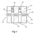
- FIG 1 shows an embodiment of progressive forming dies with a die set 10 comprising a lower die plate 11 and an upper die plate 12.
- the lower die plate 11 has a primary forming chamber 15 and final forming chamber 16.
- the upper die plate 12 has a primary shaping plunger 13 and a second, final shaping plunger 14 , such that the primary forming chamber 15 and the primary shaping plunger 13 are aligned. Likewise, the final forming chamber 16 and the final shaping plunger 14 are aligned.
- the upper die plate 12 may be movable upwards from lower die plate 11, or the lower die plate 11 may be movable downwards from the upper die plate 12, thereby creating a space 19 between the die plates allowing a film, for example a laminate containing a metal foil-plastic layer 20 to be inserted between the die plates.
- the primary shaping plunger 13 has a shaped surface 17, which is positioned to drive into the film 20 and produce a primary contour 21 (shown in FIG 2 ).
- Final shaping plunger 14 has a shaped surface 18 which is positioned to drive into the film 20 and produce a final contour 22 (shown in FIG 3 ).
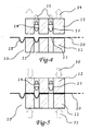
- FIG 2 shows the upper die plate 12 pressed against the lower die plate 11 by forces 30 and 31 clamping the film 20 firmly between the die plates.
- the primary contour 21 has already been formed in the film 20 and positioned under the final shaping plunger 14.
- the embodiment of FIG 3 shows the primary shaping plunger 13 being driven into the film 20 by force 33, creating primary contour 21 in the film 20.
- the final shaping plunger 14 is driven into the primary contour 21 by force 34 creating final contour 22.
- the depth of the primary contour 21 is greater than the final contour 22.
- FIG 4 shows the plungers retracted by force 35 and the upper die plate 12 opened upward by force 34.
- the opening of the die set 10 allows the film 20 to be advanced as shown by the arrow such that an unformed area 23 of the film 20 is positioned below the primary shaping plunger 13, the primary contour 21 is repositioned under the final shaping plunger 14, and the final contour 22 is removed from the die set 10.
- the embodiment of FIG 5 shows the die set 10 clamped by forces 30 and 31 and the film 20 in position for the next forming step similar to step 1 shown in FIG 2 .
- final contours 22 are produced and are ready for placement of medication, pills, devices, etc. into the formed blister for sealing into the complete package.
- FIG 6 shows a plan view of a single strip of film 20 positioned over the lower die plate 11 with a single row of forming chambers 15 and 16. Such a configuration produces a strip of formed blister shapes in a single row.
- FIG 7 shows a strip of film 50 that is wide enough for five rows of forming dies over a lower die set 41 which contains five rows of forming chambers 45 and 46. It will be obvious to one of skill in the art that any number of rows of shaping dies and chambers can be incorporated into a die set. Five are shown to illustrate the principle only.
- FIG 8 shows a cross section through the single row die set 10 with final contours 22 produced in a single row.
- FIG 9 shows a cross section through the primary shaping plungers 43 of the five station die set 40. A cross section through any one of the five rows of forming dies would look like FIG 8 .
- FIG 10 shows the difference in Area Ratio and Draw Ratio for three different shapes with the same draw ratio. Shapes 1, 2 and 3 represent vastly different amounts of stretch of the film, as well as varying levels of difficulty to form. As shown, while the Draw Ratio does not distinguish between these differences, the Area Ratio is very descriptive of the degree of film forming in each case. If the film is drawn substantially uniform in the formed recess, the new thickness could be calculated as the Original Material Thickness/Area Ratio.
- the Area Ratio for each of the three shapes shown in FIG 10 is calculated as follows:
- FIG 11 shows a top view of a sealed blister package 60 with formed shapes 73 in the sealing area 72 of the lid stock 70.
- the contact point 71 is produced by the top of the nozzle of an internal piercer 62 (shown in FIG 12).
- FIG 12 shows a cross section of a sealed blister package 60 with an internal piercer 62 held in position within the shaped blister 61. The nozzle of the piercer 62 is held against the lid stock 70 at contact point 71.
- the seal is strengthened by the incorporation of formed shapes 73 in the seal area 72.
Landscapes
- Mechanical Engineering (AREA)
- Engineering & Computer Science (AREA)
- Health & Medical Sciences (AREA)
- General Health & Medical Sciences (AREA)
- Veterinary Medicine (AREA)
- Pharmacology & Pharmacy (AREA)
- Life Sciences & Earth Sciences (AREA)
- Animal Behavior & Ethology (AREA)
- Chemical & Material Sciences (AREA)
- Public Health (AREA)
- Composite Materials (AREA)
- Packages (AREA)
- Wrappers (AREA)
- Blow-Moulding Or Thermoforming Of Plastics Or The Like (AREA)
- Medical Preparation Storing Or Oral Administration Devices (AREA)
- Containers And Plastic Fillers For Packaging (AREA)
- Containers Having Bodies Formed In One Piece (AREA)
Applications Claiming Priority (2)
| Application Number | Priority Date | Filing Date | Title |
|---|---|---|---|
| US97263407P | 2007-09-14 | 2007-09-14 | |
| PCT/US2008/076399 WO2009036422A1 (en) | 2007-09-14 | 2008-09-15 | Deep draw container forming method |
Publications (3)
| Publication Number | Publication Date |
|---|---|
| EP2200909A1 EP2200909A1 (en) | 2010-06-30 |
| EP2200909A4 EP2200909A4 (en) | 2013-01-02 |
| EP2200909B1 true EP2200909B1 (en) | 2014-12-17 |
Family
ID=40452563
Family Applications (1)
| Application Number | Title | Priority Date | Filing Date |
|---|---|---|---|
| EP08830549.5A Active EP2200909B1 (en) | 2007-09-14 | 2008-09-15 | Deep draw container forming method and device |
Country Status (6)
| Country | Link |
|---|---|
| US (3) | US7963089B2 (ja) |
| EP (1) | EP2200909B1 (ja) |
| JP (2) | JP2010538925A (ja) |
| CN (2) | CN103707452B (ja) |
| CA (2) | CA2886525A1 (ja) |
| WO (1) | WO2009036422A1 (ja) |
Families Citing this family (32)
| Publication number | Priority date | Publication date | Assignee | Title |
|---|---|---|---|---|
| JP2007534384A (ja) * | 2004-04-23 | 2007-11-29 | ミスティック ファーマシューティカルズ, インコーポレイテッド | 複数の単位用量の薬物送達システム |
| BRPI0806474A2 (pt) | 2007-01-09 | 2011-09-27 | Mystic Pharmaceuticals Inc | dispositivos de cartucho intranasal |
| CN105776119B (zh) | 2007-05-16 | 2019-04-23 | 神秘制药公司 | 组成物单位剂量分配容器 |
| US8683995B2 (en) | 2007-05-16 | 2014-04-01 | Mystic Pharmaceuticals, Inc. | Dose dispensing containers |
| US9248076B2 (en) | 2007-05-16 | 2016-02-02 | Mystic Pharmaceuticals, Inc. | Dose dispensing containers |
| US8579856B2 (en) | 2007-05-16 | 2013-11-12 | Mystic Pharmaceuticals, Inc. | Unit dose drug delivery platform |
| WO2009036422A1 (en) | 2007-09-14 | 2009-03-19 | Mystic Pharmaceuticals, Inc. | Deep draw container forming method |
| ITMO20080085A1 (it) * | 2008-03-25 | 2009-09-26 | Sarong Spa | Apparato per formare contenitori asettici |
| BRPI0921217A2 (pt) * | 2008-11-10 | 2016-02-23 | Eco Logic Brands | recipientes termo-conformados para conter líquidos |
| US9132243B2 (en) * | 2010-07-23 | 2015-09-15 | Tannermedico A/S | Method of administering a substance to the throat |
| AU2011360195B2 (en) * | 2011-02-21 | 2016-04-21 | Automated Packaging Systems, Inc. | Packaging machine and process |
| PL2511075T3 (pl) * | 2011-04-15 | 2014-02-28 | Uhlmann Pac Systeme Gmbh & Co Kg | Urządzenie do formowania na zimno blistrów w folii dla produktów medycznych lub farmaceutycznych |
| PL2704895T3 (pl) * | 2011-05-03 | 2015-11-30 | Unilever Nv | Sposób wytwarzania uformowanego termoplastycznego materiału |
| US8585659B2 (en) | 2011-05-31 | 2013-11-19 | Mystic Pharmaceuticals, Inc. | Piercing device for drug delivery systems |
| FI124947B (fi) * | 2012-03-19 | 2015-04-15 | Stora Enso Oyj | Syvävedetty paperivuoka, menetelmä ja laitteisto sen valmistamiseksi, ja vuokamallinen tuotepakkaus |
| USD693695S1 (en) | 2012-03-28 | 2013-11-19 | Aventisub Ii Inc. | Package for product |
| USD695625S1 (en) | 2012-03-28 | 2013-12-17 | Aventisub Ii Inc. | Package for product |
| USD694644S1 (en) | 2012-03-28 | 2013-12-03 | Aventisub Ii Inc. | Clamshell package having blisters |
| US8919559B2 (en) | 2012-03-28 | 2014-12-30 | Aventisub Ii Inc. | Package with break-away clamshell |
| USD697813S1 (en) | 2012-03-28 | 2014-01-21 | Aventisub Ii Inc. | Clamshell having blisters received therein |
| US8899419B2 (en) | 2012-03-28 | 2014-12-02 | Aventisub Ii Inc. | Package with break-away clamshell |
| USD687313S1 (en) | 2012-03-28 | 2013-08-06 | Aventisub Ii Inc. | A-shaped blister card |
| US9150119B2 (en) | 2013-03-15 | 2015-10-06 | Aesynt Incorporated | Apparatuses, systems, and methods for anticipating and delivering medications from a central pharmacy to a patient using a track based transport system |
| US9511945B2 (en) | 2012-10-12 | 2016-12-06 | Aesynt Incorporated | Apparatuses, systems, and methods for transporting medications from a central pharmacy to a patient in a healthcare facility |
| JP6301064B2 (ja) * | 2013-03-21 | 2018-03-28 | 東洋アルミニウム株式会社 | プレススルーパックの蓋材およびプレススルーパック包装体 |
| GB201312228D0 (en) | 2013-07-08 | 2013-08-21 | Ludlow Michael | A lip skin and a method and apparatus for forming a lip skin |
| DE102014106427A1 (de) * | 2014-05-08 | 2015-11-12 | Technische Universität Dresden | Verfahren und Vorrichtung zur Herstellung von Formteilen aus einer Faserwerkstoffbahn |
| US10688260B2 (en) | 2015-09-24 | 2020-06-23 | Mystic Pharmaceuticals, Inc. | Devices and systems for air assisted dry powder administration |
| US20170137159A1 (en) * | 2015-11-13 | 2017-05-18 | Mystic Pharmaceuticals, Inc. | Deep Draw Container Forming Method and Nutritional Product Containers |
| DE102017109879A1 (de) * | 2017-05-08 | 2018-11-08 | Pester Pac Automation Gmbh | Verfahren zum dreidimensionalen Umformen von flächigem Material |
| JP7305928B2 (ja) * | 2018-07-10 | 2023-07-11 | 東洋製罐株式会社 | フィルムの立体加工方法 |
| CN112060648B (zh) * | 2020-08-27 | 2022-07-29 | 京东方科技集团股份有限公司 | 一种泡罩制备装置及方法 |
Family Cites Families (147)
| Publication number | Priority date | Publication date | Assignee | Title |
|---|---|---|---|---|
| US1870558A (en) * | 1928-06-22 | 1932-08-09 | Adela N Darby | Device for treating nasal and pulmonary afflictions |
| US2105946A (en) * | 1935-12-06 | 1938-01-18 | Sidney M Lewis | Applicator |
| US2307980A (en) * | 1941-05-09 | 1943-01-12 | Jr Walter Lee Avrett | Tractor plow |
| US2332799A (en) * | 1942-01-10 | 1943-10-26 | Stanco Inc | Atomizer |
| GB588117A (en) * | 1945-01-29 | 1947-05-14 | John Terry Hayward Butt | Improvements in or relating to inhalers for analgesic or anaesthetic purposes |
| US2706984A (en) * | 1953-03-19 | 1955-04-26 | Gloacchino Lipari | Plunger assembly and disposable medicament cartridge for use therewith |
| US2769443A (en) | 1954-09-29 | 1956-11-06 | Russell P Dunmire | Hypodermic devices |
| US2885931A (en) * | 1955-08-11 | 1959-05-12 | Julius M Mcdonald | Hub cap locking device |
| US3507277A (en) * | 1966-09-17 | 1970-04-21 | Fisons Pharmaceuticals Ltd | Inhalation device |
| GB1217152A (en) * | 1967-03-14 | 1970-12-31 | Arthur Bane | Improvements in appliances for storing and dispensing fluids, such as hypodermic syringes and eye drop dispensers |
| US3457761A (en) * | 1967-03-20 | 1969-07-29 | Western Electric Co | Method and apparatus for drawing and stretching a flat blank into a tubular shell |
| US3949751A (en) * | 1970-03-03 | 1976-04-13 | Fisons Limited | Method and device for dispensing medicament to the body |
| US3888253A (en) * | 1972-08-04 | 1975-06-10 | Beecham Group Ltd | Device for administration of medicines |
| FR2224175B1 (ja) * | 1973-04-04 | 1978-04-14 | Isf Spa | |
| JPS5418545Y2 (ja) * | 1973-04-24 | 1979-07-12 | ||
| US4017007A (en) * | 1973-12-26 | 1977-04-12 | Ciba-Geigy Corporation | Single dose air pressure operated dispenser |
| US3971377A (en) * | 1974-06-10 | 1976-07-27 | Alza Corporation | Medicament dispensing process for inhalation therapy |
| IT1017153B (it) * | 1974-07-15 | 1977-07-20 | Isf Spa | Apparecchio per inalazioni |
| US3948264A (en) * | 1975-05-21 | 1976-04-06 | Mead Johnson & Company | Inhalation device |
| GB1521000A (en) * | 1975-06-13 | 1978-08-09 | Syntex Puerto Rico Inc | Inhalation device |
| GB1518998A (en) | 1975-08-28 | 1978-07-26 | Gillette Co | Packaging flowable materials |
| GB1562732A (en) * | 1976-02-10 | 1980-03-12 | Allen & Hanburys Ltd | Device for dispensing medicaments |
| US4095596A (en) * | 1976-11-26 | 1978-06-20 | Smithkline Corporation | Nasal inhaler |
| IE46865B1 (en) * | 1977-04-29 | 1983-10-19 | Allen & Hanburys Ltd | Device for dispensing medicaments |
| JPS6020181B2 (ja) * | 1979-01-12 | 1985-05-20 | 積水化成品工業株式会社 | 内部に中空部を有する二重成形品の製造方法 |
| JPS56164817A (en) * | 1980-05-23 | 1981-12-18 | Sumitomo Bakelite Co Ltd | Production of thin-walled cup-shaped container |
| DE3167567D1 (en) * | 1980-06-06 | 1985-01-17 | Fisons Plc | Inhalation device for powdered medicaments |
| JPS5746463U (ja) * | 1980-08-29 | 1982-03-15 | ||
| DE8224022U1 (de) | 1981-02-05 | 1983-11-10 | Firmenich S.A., 1211 Genève | Kunststoffverpackung mit mehreren Kammern fuer feste und fluessige Produkte |
| US4623337A (en) | 1984-03-08 | 1986-11-18 | Alpha Group, Inc. | Liquid dispensing apparatus |
| JPS6125818A (ja) * | 1984-07-16 | 1986-02-04 | Yoshino Kogyosho Co Ltd | 合成樹脂製シ−ト容器の成形方法 |
| US5048727A (en) | 1984-11-02 | 1991-09-17 | Alcon Laboratories, Inc. | Preassembled unit dose dispenser having a compressible container and a tube prefilled with a unit dose of opthalmic gel. |
| US4684366A (en) | 1985-03-15 | 1987-08-04 | Denny Christopher G | Syringe for the remote injection of animals and fish |
| GB8528032D0 (en) | 1985-11-13 | 1985-12-18 | Ici Plc | Ocular treatment |
| US4896832A (en) * | 1987-09-07 | 1990-01-30 | Bespak Plc | Dispensing apparatus for metered quantities of pressurised fluid |
| JPH01165421A (ja) * | 1987-12-21 | 1989-06-29 | Ckd Corp | 耐熱性合成樹脂容器の成形方法及び装置 |
| US4852551A (en) | 1988-04-22 | 1989-08-01 | Opielab, Inc. | Contamination-free endoscope valves for use with a disposable endoscope sheath |
| BR8801952A (pt) | 1988-04-22 | 1989-11-14 | Sergio Landau | Capsula descartavel,nao re-utilizavel,contendo dose individual de vacina a ser injetada hipodermicamente,sem agulha,com aparelho injetor a pressao |
| DE68913596T2 (de) | 1988-06-09 | 1994-09-29 | John Leslie Williams | Vorrichtung für Augenheilkunde. |
| JP2548783B2 (ja) * | 1988-12-15 | 1996-10-30 | 昭和電工株式会社 | 真空成形容器の製造方法 |
| IT1228460B (it) * | 1989-02-23 | 1991-06-19 | Phidea S R L | Inalatore monouso con capsula pre-forata |
| IT1228459B (it) * | 1989-02-23 | 1991-06-19 | Phidea S R L | Inalatore con svuotamento regolare e completo della capsula. |
| US5219101A (en) | 1989-06-01 | 1993-06-15 | Pall Corporation | Contamination-resistant dispensing and metering drop forming device |
| DE8907589U1 (ja) * | 1989-06-21 | 1989-08-10 | William Prym-Werke Gmbh & Co Kg, 5190 Stolberg, De | |
| DE4021263C2 (de) | 1990-07-04 | 1996-04-11 | Pfeiffer Erich Gmbh & Co Kg | Austragvorrichtung für Medien |
| IT1243344B (it) * | 1990-07-16 | 1994-06-10 | Promo Pack Sa | Inalatore plurimonodose per medicamenti in polvere |
| US5327883A (en) * | 1991-05-20 | 1994-07-12 | Dura Pharmaceuticals, Inc. | Apparatus for aerosolizing powdered medicine and process and using |
| US5492112A (en) * | 1991-05-20 | 1996-02-20 | Dura Pharmaceuticals, Inc. | Dry powder inhaler |
| US5337740A (en) | 1991-08-01 | 1994-08-16 | New England Pharmaceuticals, Inc. | Inhalation devices |
| US5287850A (en) * | 1991-08-20 | 1994-02-22 | Habley Medical Technology Corporation | Timing and velocity controlled powered pharmaceutical inhaler |
| GB9125699D0 (en) | 1991-12-03 | 1992-01-29 | Glaxo Group Ltd | Device |
| DK198591D0 (da) * | 1991-12-10 | 1991-12-10 | Novo Nordisk As | Apparat |
| AT398037B (de) | 1992-01-10 | 1994-08-25 | Med Plastic Ag | Vorrichtung zur selbst-injektion |
| GB9203761D0 (en) * | 1992-02-21 | 1992-04-08 | Innovata Biomed Ltd | Inhaler |
| US5267986A (en) | 1992-04-06 | 1993-12-07 | Self-Instill & Co., Inc. | Cartridge for applying medicament to an eye from a dispenser |
| US5215221A (en) | 1992-05-07 | 1993-06-01 | The Procter & Gamble Company | Disposable unit dose dispenser for powdered medicants |
| US5431155A (en) * | 1992-06-03 | 1995-07-11 | Elettro Plastica S.P.A. | Single-dose nasal dispenser for atomized liquid drugs |
| US6703066B1 (en) | 1992-07-10 | 2004-03-09 | Robert R. Holcomb | Flavor enhancer composition containing colloidal silica and method for its preparation and use |
| US5273190A (en) | 1992-07-27 | 1993-12-28 | Lund William J | Quick shot single barrel dispensing system |
| GB9216038D0 (en) * | 1992-07-28 | 1992-09-09 | Bespak Plc | Dispensing apparatus for powdered medicaments |
| US5547131A (en) * | 1992-12-04 | 1996-08-20 | Bespak Plc | Dispensing device with spray nozzle and driven piston |
| US5425480A (en) | 1992-12-17 | 1995-06-20 | Ryder International Corporation | Dose dispenser having a molded plastic housing with a cavity and a metallic foil wall covering the cavity |
| US5896855A (en) * | 1992-12-24 | 1999-04-27 | Rhone-Poulenc Rorer Limited | Multi dose inhaler apparatus |
| CH684746A5 (de) * | 1993-02-25 | 1994-12-15 | Alusuisse Lonza Services Ag | Laminat. |
| US5411175A (en) * | 1993-03-08 | 1995-05-02 | New England Pharmaceuticals, Inc. | Cartridges, devices and methods for dispensing liquids |
| US5497763A (en) | 1993-05-21 | 1996-03-12 | Aradigm Corporation | Disposable package for intrapulmonary delivery of aerosolized formulations |
| US5433343A (en) * | 1993-07-30 | 1995-07-18 | Meshberg; Philip | Delivery system for measured quantities of liquids, especially medications |
| DE4412041A1 (de) | 1994-04-08 | 1995-10-12 | Pfeiffer Erich Gmbh & Co Kg | Austragvorrichtung für fließfähige Medien, insbesondere für den Austrag in nur einem Hub |
| US5944222A (en) | 1994-04-08 | 1999-08-31 | Ing. Erich Pfeiffer Gmbh | Tamper evident discharge apparatus for flowable media |
| JP3372105B2 (ja) * | 1994-05-26 | 2003-01-27 | 株式会社日立ユニシアオートモティブ | 吸入式投薬器 |
| CH689305A5 (de) * | 1994-08-23 | 1999-02-15 | Alusuisse Lonza Services Ag | Blisterpackung. |
| GB9417399D0 (en) | 1994-08-30 | 1994-10-19 | Scherer Corp R P | Ocular treatment device |
| BR9508964A (pt) * | 1994-09-21 | 1998-06-02 | Inhale Therapeutic Syst | Processo e aparelho de aerossolização conjunto de tubo de alimentação e receptáculo para contenção de um medicamento pulverizado |
| US5524419A (en) * | 1995-02-02 | 1996-06-11 | Bausch & Lomb Incorporated | Method and apparatus for molding contact lenses and making their container |
| US5901703A (en) * | 1995-02-06 | 1999-05-11 | Unisia Jecs Corporation | Medicine administering device for nasal cavities |
| JP3308425B2 (ja) * | 1995-03-10 | 2002-07-29 | 株式会社ユニシアジェックス | 鼻腔用投薬器 |
| ES2140069T3 (es) * | 1995-03-14 | 2000-02-16 | Siemens Ag | Dispositivo atomizador ultrasonico con unidad dosificadora de precision desmontable. |
| JP3142577B2 (ja) * | 1995-03-14 | 2001-03-07 | シーメンス アクチエンゲゼルシヤフト | 着脱自在な精密計量供給ユニット |
| US5645810A (en) * | 1995-06-07 | 1997-07-08 | Aluminum Company Of America | High surface area meixnerite from hydrotalcites |
| JP3317827B2 (ja) * | 1995-10-09 | 2002-08-26 | 株式会社ユニシアジェックス | 投薬器 |
| EP0779143B1 (de) * | 1995-12-12 | 2001-03-07 | Alusuisse Technology & Management AG | Verfahren zum Herstellen von Blisterverpackungen |
| US5678444A (en) * | 1996-01-23 | 1997-10-21 | Nagamori; Hachiro | Method of sequentially manufacturing hollow knock pins |
| US5643211A (en) * | 1996-02-29 | 1997-07-01 | Medi-Ject Corporation | Nozzle assembly having a frangible plunger |
| AUPN976496A0 (en) * | 1996-05-10 | 1996-05-30 | Glaxo Wellcome Australia Ltd | Unit dose dispensing device |
| GB2316451B (en) * | 1996-08-15 | 2000-09-13 | Tenax Corp | Dispensing device |
| US5769278A (en) | 1996-09-27 | 1998-06-23 | Kummer; Frederick J. | Adjustable measured dose dropper |
| DE19647947A1 (de) * | 1996-11-20 | 1998-05-28 | Pfeiffer Erich Gmbh & Co Kg | Austragvorrichtung für Medien |
| DE19723133A1 (de) | 1997-06-03 | 1998-12-10 | Caideil M P Teoranta Tourmakea | Austragvorrichtung für Medien |
| DE19704849B4 (de) * | 1997-02-08 | 2011-02-17 | Ing. Erich Pfeiffer Gmbh | Austragvorrichtung für Medien |
| PT101988B (pt) * | 1997-04-04 | 2004-02-27 | Hovione Farmaciencia Sa | Sistema de orientacao e posicionamento de um objecto |
| US5908664A (en) * | 1997-04-25 | 1999-06-01 | Nagayama Electronic Industry Co., Ltd. | Method of working metal member |
| TW379182B (en) * | 1997-07-23 | 2000-01-11 | Matsushita Electric Ind Co Ltd | Packing materials for small parts, packing method and packing apparatus as well as the packing method for electronic parts |
| DE29714246U1 (de) | 1997-08-08 | 1998-12-10 | Thera Ges Fuer Patente | Vorrichtung zum Lagern und Auftragen einer fließfähigen Substanz |
| DE19749514A1 (de) * | 1997-11-08 | 1999-05-12 | Pfeiffer Erich Gmbh & Co Kg | Verfahren zum Ausbringen von wenigstens zwei verschiedenen Medien und Spender dafür |
| US6116238A (en) | 1997-12-02 | 2000-09-12 | Dura Pharmaceuticals, Inc. | Dry powder inhaler |
| DE19831525A1 (de) * | 1998-07-14 | 2000-01-20 | Pfeiffer Erich Gmbh & Co Kg | Spender für Medien |
| US6269671B1 (en) * | 1998-09-16 | 2001-08-07 | Alusuisse Technology & Management Ltd. | Process for manufacturing shaped packaging |
| US6708846B1 (en) | 1999-02-14 | 2004-03-23 | Ing. Erich Pfeiffer Gmbh | Dispenser for flowable media |
| JP2000289111A (ja) * | 1999-04-12 | 2000-10-17 | Kao Corp | 複合容器の製造方法 |
| EP1048746B1 (de) * | 1999-04-28 | 2005-09-21 | Alcan Technology & Management AG | Verfahren und Vorrichtung zur Herstellung von Packungen |
| US6138439A (en) * | 1999-05-21 | 2000-10-31 | Illinois Tool Works Inc. | Methods of making slide-zippered reclosable packages on horizontal form-fill-seal machines |
| US6606992B1 (en) * | 1999-06-30 | 2003-08-19 | Nektar Therapeutics | Systems and methods for aerosolizing pharmaceutical formulations |
| US6375956B1 (en) * | 1999-07-22 | 2002-04-23 | Drugtech Corporation | Strip pack |
| DE29912954U1 (de) * | 1999-07-24 | 2000-12-14 | Coripharm Medizinprodukte Gmbh | Blisterverpackung |
| DE19940236A1 (de) * | 1999-08-25 | 2001-03-08 | Pfeiffer Erich Gmbh & Co Kg | Spender mit manuell betätigbarer Ausbringeinrichtung |
| DE19942791A1 (de) * | 1999-09-08 | 2001-03-15 | Pfeiffer Erich Gmbh & Co Kg | Spender für Medien |
| DE19944209A1 (de) * | 1999-09-15 | 2001-03-22 | Pfeiffer Erich Gmbh & Co Kg | Spender zum ggf. zerstäubten Ausbringen eines insbesondere flüssigen Mediums aus einem Behältnis |
| US6382204B1 (en) * | 1999-10-14 | 2002-05-07 | Becton Dickinson And Company | Drug delivery system including holder and drug container |
| EP1106644B1 (en) * | 1999-12-08 | 2007-07-11 | Nipro Corporation | Easily peelable film and medical packaging container |
| US6810872B1 (en) * | 1999-12-10 | 2004-11-02 | Unisia Jecs Corporation | Inhalant medicator |
| DE19960459A1 (de) * | 1999-12-15 | 2001-06-21 | Pfeiffer Erich Gmbh & Co Kg | Spender für Medien |
| DE10011120A1 (de) | 2000-03-09 | 2001-09-13 | Pfeiffer Erich Gmbh & Co Kg | Spender für Medien |
| EP1163995A1 (de) * | 2000-06-16 | 2001-12-19 | Alcan Technology & Management AG | Vorrichtung zur Formung von Folien mit Vertiefungen |
| DE10036594A1 (de) * | 2000-07-27 | 2002-02-07 | Pfeiffer Erich Gmbh & Co Kg | Austragvorrichtung für Medien |
| DE10056212B4 (de) | 2000-11-13 | 2005-08-18 | 3M Espe Ag | Vorrichtung zum Lagern und Ausbringen von fließfähigen Zusammensetzungen, Verfahren zur Herstellung und Verwendung der Vorrichtung |
| JP3871877B2 (ja) * | 2000-11-22 | 2007-01-24 | シーケーディ株式会社 | ラミネートフィルムの成形装置 |
| US6644309B2 (en) | 2001-01-12 | 2003-11-11 | Becton, Dickinson And Company | Medicament respiratory delivery device and method |
| US6722364B2 (en) | 2001-01-12 | 2004-04-20 | Becton, Dickinson And Company | Medicament inhalation delivery devices and methods for using the same |
| US6443152B1 (en) * | 2001-01-12 | 2002-09-03 | Becton Dickinson And Company | Medicament respiratory delivery device |
| US6782887B2 (en) | 2001-01-12 | 2004-08-31 | Becton, Dickinson And Company | Medicament respiratory delivery device and cartridge |
| US6758837B2 (en) | 2001-02-08 | 2004-07-06 | Pharmacia Ab | Liquid delivery device and method of use thereof |
| DE10110742A1 (de) * | 2001-02-28 | 2002-09-05 | Pfeiffer Erich Gmbh & Co Kg | Spender für Medien |
| US6766799B2 (en) * | 2001-04-16 | 2004-07-27 | Advanced Inhalation Research, Inc. | Inhalation device |
| US7235063B2 (en) * | 2001-08-21 | 2007-06-26 | D'antonio Consultants International, Inc. | Hypodermic injection system |
| US20030105430A1 (en) * | 2001-11-30 | 2003-06-05 | Elan Pharma International Limited Wil House | Automatic injector |
| DE10164452A1 (de) * | 2001-12-21 | 2003-07-03 | Pfeiffer Erich Gmbh & Co Kg | Spender für Medien |
| ITMI20020078A1 (it) * | 2002-01-16 | 2003-07-16 | Fabrizio Niccolai | Dispositivo utilizzabile nel tratamento di affezzioni delle vie respiratorie |
| DE10218782A1 (de) * | 2002-04-22 | 2003-11-20 | Pfeiffer Erich Gmbh & Co Kg | Dosiervorrichtung mit wenigstens zwei Medienräumen |
| US6889690B2 (en) * | 2002-05-10 | 2005-05-10 | Oriel Therapeutics, Inc. | Dry powder inhalers, related blister devices, and associated methods of dispensing dry powder substances and fabricating blister packages |
| US6715810B2 (en) * | 2002-09-09 | 2004-04-06 | Oregon Precision Industries, Inc. | Three bottle carrier |
| US6899717B2 (en) | 2002-09-18 | 2005-05-31 | Allergan, Inc. | Methods and apparatus for delivery of ocular implants |
| US7516741B2 (en) * | 2002-12-06 | 2009-04-14 | Novartis Ag | Aerosolization apparatus with feedback mechanism |
| US20050081852A1 (en) * | 2002-12-30 | 2005-04-21 | Nektar Therapeutics (Formely Inhale Therapeutic System Inc.) | Package for an aerosolization apparatus and pharmaceutical formulation receptacle |
| US20050056280A1 (en) * | 2002-12-31 | 2005-03-17 | Nektar Therapeutics | Receptacle for an aerosolizable pharmaceutical formulation |
| US7669596B2 (en) * | 2002-12-31 | 2010-03-02 | Novartis Pharma Ag | Aerosolization apparatus with rotating capsule |
| GB2398253B (en) * | 2003-02-11 | 2005-08-31 | Bespak Plc | Dispensing apparatus |
| US10207066B2 (en) * | 2003-04-09 | 2019-02-19 | Bgp Products Operations Gmbh | Aerosolization apparatus with capsule puncture alignment guide |
| MXPA05010842A (es) * | 2003-04-09 | 2006-03-30 | Nektar Therapeutics | Aparato de nebulizacion con protector de entrada de aire. |
| WO2005032998A1 (en) | 2003-10-02 | 2005-04-14 | The X Group, Inc | Portable dispensing systems |
| US7074302B2 (en) * | 2003-12-05 | 2006-07-11 | Sonoco Development, Inc. | Apparatus and process for forming three-dimensional fibrous panels |
| JP2007534384A (ja) | 2004-04-23 | 2007-11-29 | ミスティック ファーマシューティカルズ, インコーポレイテッド | 複数の単位用量の薬物送達システム |
| DE202005001203U1 (de) | 2005-01-26 | 2006-06-14 | Sulzer Chemtech Ag | Mehrkomponentenfolienbehälter |
| BRPI0806474A2 (pt) | 2007-01-09 | 2011-09-27 | Mystic Pharmaceuticals Inc | dispositivos de cartucho intranasal |
| US8579856B2 (en) | 2007-05-16 | 2013-11-12 | Mystic Pharmaceuticals, Inc. | Unit dose drug delivery platform |
| CN105776119B (zh) * | 2007-05-16 | 2019-04-23 | 神秘制药公司 | 组成物单位剂量分配容器 |
| WO2009036422A1 (en) | 2007-09-14 | 2009-03-19 | Mystic Pharmaceuticals, Inc. | Deep draw container forming method |
| ITMO20080085A1 (it) * | 2008-03-25 | 2009-09-26 | Sarong Spa | Apparato per formare contenitori asettici |
-
2008
- 2008-09-15 WO PCT/US2008/076399 patent/WO2009036422A1/en active Application Filing
- 2008-09-15 JP JP2010525064A patent/JP2010538925A/ja active Pending
- 2008-09-15 US US12/210,862 patent/US7963089B2/en active Active
- 2008-09-15 EP EP08830549.5A patent/EP2200909B1/en active Active
- 2008-09-15 CA CA 2886525 patent/CA2886525A1/en not_active Abandoned
- 2008-09-15 CN CN201310447257.7A patent/CN103707452B/zh active Active
- 2008-09-15 CN CN2008801069651A patent/CN101801812B/zh active Active
- 2008-09-15 CA CA2699634A patent/CA2699634C/en active Active
-
2011
- 2011-06-03 US US13/153,081 patent/US8272194B2/en active Active
-
2012
- 2012-09-24 US US13/625,614 patent/US9446874B2/en active Active
-
2014
- 2014-01-10 JP JP2014003685A patent/JP5965929B2/ja active Active
Also Published As
| Publication number | Publication date |
|---|---|
| US20090071108A1 (en) | 2009-03-19 |
| CA2699634A1 (en) | 2009-03-19 |
| US20130097972A1 (en) | 2013-04-25 |
| US7963089B2 (en) | 2011-06-21 |
| JP2010538925A (ja) | 2010-12-16 |
| US9446874B2 (en) | 2016-09-20 |
| WO2009036422A1 (en) | 2009-03-19 |
| US20110247305A1 (en) | 2011-10-13 |
| JP2014129144A (ja) | 2014-07-10 |
| CA2886525A1 (en) | 2009-03-19 |
| JP5965929B2 (ja) | 2016-08-10 |
| US8272194B2 (en) | 2012-09-25 |
| EP2200909A1 (en) | 2010-06-30 |
| CN103707452B (zh) | 2017-05-03 |
| CN101801812B (zh) | 2013-10-23 |
| CN103707452A (zh) | 2014-04-09 |
| CN101801812A (zh) | 2010-08-11 |
| CA2699634C (en) | 2015-06-09 |
| EP2200909A4 (en) | 2013-01-02 |
Similar Documents
| Publication | Publication Date | Title |
|---|---|---|
| EP2200909B1 (en) | Deep draw container forming method and device | |
| US20170137159A1 (en) | Deep Draw Container Forming Method and Nutritional Product Containers | |
| AU703723B2 (en) | Process for manufacturing shaped forms of packaging | |
| US6430984B2 (en) | Process for manufacturing shaped packaging | |
| JP2000500710A (ja) | 成形された包装形態物の製造方法 | |
| EP2321114B1 (en) | Method of making shoulder/nozzels with film barrier liners | |
| MX2010009484A (es) | Tapa de papel metalico recubierta por extrusion para empaquetado vesicular a presion. | |
| CN102811909A (zh) | 盖整形装置 | |
| RU2008143345A (ru) | Микролинзовые окна и кодированные изображения для упаковки и печати и способы их изготовления | |
| EP3348380A1 (en) | Labels for containers and methods of making labels | |
| CN107399516B (zh) | 容器用层叠片材及容器 | |
| TW201429824A (zh) | 破壞性密封件 | |
| CN110524976B (zh) | 成型容器用层叠体、成型容器及包装体 | |
| US10238577B2 (en) | Oral delivery device and methods | |
| EP3257966A1 (de) | Verfahren und vorrichtung zum beschichten von verpackungsbehältern | |
| KR20190134483A (ko) | 성형 용기용 적층체, 성형 용기 및 포장체 | |
| KR20190115414A (ko) | 성형 용기용 적층체, 성형 용기 및 포장체 | |
| JP2020104877A (ja) | 容器用蓋材および包装体 |
Legal Events
| Date | Code | Title | Description |
|---|---|---|---|
| PUAI | Public reference made under article 153(3) epc to a published international application that has entered the european phase |
Free format text: ORIGINAL CODE: 0009012 |
|
| 17P | Request for examination filed |
Effective date: 20100413 |
|
| AK | Designated contracting states |
Kind code of ref document: A1 Designated state(s): AT BE BG CH CY CZ DE DK EE ES FI FR GB GR HR HU IE IS IT LI LT LU LV MC MT NL NO PL PT RO SE SI SK TR |
|
| AX | Request for extension of the european patent |
Extension state: AL BA MK RS |
|
| RIN1 | Information on inventor provided before grant (corrected) |
Inventor name: NELSON, JEFFREY Inventor name: OLSON, JON |
|
| DAX | Request for extension of the european patent (deleted) | ||
| A4 | Supplementary search report drawn up and despatched |
Effective date: 20121204 |
|
| RIC1 | Information provided on ipc code assigned before grant |
Ipc: B29C 51/04 20060101ALI20121128BHEP Ipc: B65D 83/04 20060101ALI20121128BHEP Ipc: B65D 85/42 20060101AFI20121128BHEP |
|
| GRAP | Despatch of communication of intention to grant a patent |
Free format text: ORIGINAL CODE: EPIDOSNIGR1 |
|
| INTG | Intention to grant announced |
Effective date: 20140708 |
|
| GRAS | Grant fee paid |
Free format text: ORIGINAL CODE: EPIDOSNIGR3 |
|
| GRAA | (expected) grant |
Free format text: ORIGINAL CODE: 0009210 |
|
| AK | Designated contracting states |
Kind code of ref document: B1 Designated state(s): AT BE BG CH CY CZ DE DK EE ES FI FR GB GR HR HU IE IS IT LI LT LU LV MC MT NL NO PL PT RO SE SI SK TR |
|
| REG | Reference to a national code |
Ref country code: GB Ref legal event code: FG4D |
|
| REG | Reference to a national code |
Ref country code: CH Ref legal event code: EP |
|
| REG | Reference to a national code |
Ref country code: IE Ref legal event code: FG4D |
|
| REG | Reference to a national code |
Ref country code: AT Ref legal event code: REF Ref document number: 701707 Country of ref document: AT Kind code of ref document: T Effective date: 20150115 |
|
| REG | Reference to a national code |
Ref country code: DE Ref legal event code: R096 Ref document number: 602008035943 Country of ref document: DE Effective date: 20150129 |
|
| REG | Reference to a national code |
Ref country code: CH Ref legal event code: NV Representative=s name: KELLER AND PARTNER PATENTANWAELTE AG, CH |
|
| PG25 | Lapsed in a contracting state [announced via postgrant information from national office to epo] |
Ref country code: FI Free format text: LAPSE BECAUSE OF FAILURE TO SUBMIT A TRANSLATION OF THE DESCRIPTION OR TO PAY THE FEE WITHIN THE PRESCRIBED TIME-LIMIT Effective date: 20141217 Ref country code: NO Free format text: LAPSE BECAUSE OF FAILURE TO SUBMIT A TRANSLATION OF THE DESCRIPTION OR TO PAY THE FEE WITHIN THE PRESCRIBED TIME-LIMIT Effective date: 20150317 Ref country code: LT Free format text: LAPSE BECAUSE OF FAILURE TO SUBMIT A TRANSLATION OF THE DESCRIPTION OR TO PAY THE FEE WITHIN THE PRESCRIBED TIME-LIMIT Effective date: 20141217 |
|
| REG | Reference to a national code |
Ref country code: LT Ref legal event code: MG4D |
|
| PG25 | Lapsed in a contracting state [announced via postgrant information from national office to epo] |
Ref country code: GR Free format text: LAPSE BECAUSE OF FAILURE TO SUBMIT A TRANSLATION OF THE DESCRIPTION OR TO PAY THE FEE WITHIN THE PRESCRIBED TIME-LIMIT Effective date: 20150318 Ref country code: LV Free format text: LAPSE BECAUSE OF FAILURE TO SUBMIT A TRANSLATION OF THE DESCRIPTION OR TO PAY THE FEE WITHIN THE PRESCRIBED TIME-LIMIT Effective date: 20141217 Ref country code: HR Free format text: LAPSE BECAUSE OF FAILURE TO SUBMIT A TRANSLATION OF THE DESCRIPTION OR TO PAY THE FEE WITHIN THE PRESCRIBED TIME-LIMIT Effective date: 20141217 Ref country code: SE Free format text: LAPSE BECAUSE OF FAILURE TO SUBMIT A TRANSLATION OF THE DESCRIPTION OR TO PAY THE FEE WITHIN THE PRESCRIBED TIME-LIMIT Effective date: 20141217 |
|
| REG | Reference to a national code |
Ref country code: AT Ref legal event code: MK05 Ref document number: 701707 Country of ref document: AT Kind code of ref document: T Effective date: 20141217 |
|
| PG25 | Lapsed in a contracting state [announced via postgrant information from national office to epo] |
Ref country code: NL Free format text: LAPSE BECAUSE OF FAILURE TO SUBMIT A TRANSLATION OF THE DESCRIPTION OR TO PAY THE FEE WITHIN THE PRESCRIBED TIME-LIMIT Effective date: 20141217 |
|
| PG25 | Lapsed in a contracting state [announced via postgrant information from national office to epo] |
Ref country code: RO Free format text: LAPSE BECAUSE OF FAILURE TO SUBMIT A TRANSLATION OF THE DESCRIPTION OR TO PAY THE FEE WITHIN THE PRESCRIBED TIME-LIMIT Effective date: 20141217 Ref country code: SK Free format text: LAPSE BECAUSE OF FAILURE TO SUBMIT A TRANSLATION OF THE DESCRIPTION OR TO PAY THE FEE WITHIN THE PRESCRIBED TIME-LIMIT Effective date: 20141217 Ref country code: CZ Free format text: LAPSE BECAUSE OF FAILURE TO SUBMIT A TRANSLATION OF THE DESCRIPTION OR TO PAY THE FEE WITHIN THE PRESCRIBED TIME-LIMIT Effective date: 20141217 Ref country code: PT Free format text: LAPSE BECAUSE OF FAILURE TO SUBMIT A TRANSLATION OF THE DESCRIPTION OR TO PAY THE FEE WITHIN THE PRESCRIBED TIME-LIMIT Effective date: 20150417 Ref country code: EE Free format text: LAPSE BECAUSE OF FAILURE TO SUBMIT A TRANSLATION OF THE DESCRIPTION OR TO PAY THE FEE WITHIN THE PRESCRIBED TIME-LIMIT Effective date: 20141217 Ref country code: ES Free format text: LAPSE BECAUSE OF FAILURE TO SUBMIT A TRANSLATION OF THE DESCRIPTION OR TO PAY THE FEE WITHIN THE PRESCRIBED TIME-LIMIT Effective date: 20141217 |
|
| PG25 | Lapsed in a contracting state [announced via postgrant information from national office to epo] |
Ref country code: AT Free format text: LAPSE BECAUSE OF FAILURE TO SUBMIT A TRANSLATION OF THE DESCRIPTION OR TO PAY THE FEE WITHIN THE PRESCRIBED TIME-LIMIT Effective date: 20141217 Ref country code: IS Free format text: LAPSE BECAUSE OF FAILURE TO SUBMIT A TRANSLATION OF THE DESCRIPTION OR TO PAY THE FEE WITHIN THE PRESCRIBED TIME-LIMIT Effective date: 20150417 Ref country code: PL Free format text: LAPSE BECAUSE OF FAILURE TO SUBMIT A TRANSLATION OF THE DESCRIPTION OR TO PAY THE FEE WITHIN THE PRESCRIBED TIME-LIMIT Effective date: 20141217 |
|
| REG | Reference to a national code |
Ref country code: DE Ref legal event code: R097 Ref document number: 602008035943 Country of ref document: DE |
|
| PLBE | No opposition filed within time limit |
Free format text: ORIGINAL CODE: 0009261 |
|
| STAA | Information on the status of an ep patent application or granted ep patent |
Free format text: STATUS: NO OPPOSITION FILED WITHIN TIME LIMIT |
|
| PG25 | Lapsed in a contracting state [announced via postgrant information from national office to epo] |
Ref country code: DK Free format text: LAPSE BECAUSE OF FAILURE TO SUBMIT A TRANSLATION OF THE DESCRIPTION OR TO PAY THE FEE WITHIN THE PRESCRIBED TIME-LIMIT Effective date: 20141217 |
|
| 26N | No opposition filed |
Effective date: 20150918 |
|
| PG25 | Lapsed in a contracting state [announced via postgrant information from national office to epo] |
Ref country code: IT Free format text: LAPSE BECAUSE OF FAILURE TO SUBMIT A TRANSLATION OF THE DESCRIPTION OR TO PAY THE FEE WITHIN THE PRESCRIBED TIME-LIMIT Effective date: 20141217 |
|
| PG25 | Lapsed in a contracting state [announced via postgrant information from national office to epo] |
Ref country code: SI Free format text: LAPSE BECAUSE OF FAILURE TO SUBMIT A TRANSLATION OF THE DESCRIPTION OR TO PAY THE FEE WITHIN THE PRESCRIBED TIME-LIMIT Effective date: 20141217 |
|
| PG25 | Lapsed in a contracting state [announced via postgrant information from national office to epo] |
Ref country code: LU Free format text: LAPSE BECAUSE OF FAILURE TO SUBMIT A TRANSLATION OF THE DESCRIPTION OR TO PAY THE FEE WITHIN THE PRESCRIBED TIME-LIMIT Effective date: 20150915 Ref country code: MC Free format text: LAPSE BECAUSE OF FAILURE TO SUBMIT A TRANSLATION OF THE DESCRIPTION OR TO PAY THE FEE WITHIN THE PRESCRIBED TIME-LIMIT Effective date: 20141217 |
|
| PG25 | Lapsed in a contracting state [announced via postgrant information from national office to epo] |
Ref country code: BE Free format text: LAPSE BECAUSE OF FAILURE TO SUBMIT A TRANSLATION OF THE DESCRIPTION OR TO PAY THE FEE WITHIN THE PRESCRIBED TIME-LIMIT Effective date: 20141217 |
|
| REG | Reference to a national code |
Ref country code: FR Ref legal event code: PLFP Year of fee payment: 9 |
|
| PG25 | Lapsed in a contracting state [announced via postgrant information from national office to epo] |
Ref country code: MT Free format text: LAPSE BECAUSE OF FAILURE TO SUBMIT A TRANSLATION OF THE DESCRIPTION OR TO PAY THE FEE WITHIN THE PRESCRIBED TIME-LIMIT Effective date: 20141217 |
|
| PG25 | Lapsed in a contracting state [announced via postgrant information from national office to epo] |
Ref country code: HU Free format text: LAPSE BECAUSE OF FAILURE TO SUBMIT A TRANSLATION OF THE DESCRIPTION OR TO PAY THE FEE WITHIN THE PRESCRIBED TIME-LIMIT; INVALID AB INITIO Effective date: 20080915 Ref country code: BG Free format text: LAPSE BECAUSE OF FAILURE TO SUBMIT A TRANSLATION OF THE DESCRIPTION OR TO PAY THE FEE WITHIN THE PRESCRIBED TIME-LIMIT Effective date: 20141217 |
|
| PG25 | Lapsed in a contracting state [announced via postgrant information from national office to epo] |
Ref country code: CY Free format text: LAPSE BECAUSE OF FAILURE TO SUBMIT A TRANSLATION OF THE DESCRIPTION OR TO PAY THE FEE WITHIN THE PRESCRIBED TIME-LIMIT Effective date: 20141217 |
|
| REG | Reference to a national code |
Ref country code: FR Ref legal event code: PLFP Year of fee payment: 10 |
|
| PG25 | Lapsed in a contracting state [announced via postgrant information from national office to epo] |
Ref country code: TR Free format text: LAPSE BECAUSE OF FAILURE TO SUBMIT A TRANSLATION OF THE DESCRIPTION OR TO PAY THE FEE WITHIN THE PRESCRIBED TIME-LIMIT Effective date: 20141217 |
|
| REG | Reference to a national code |
Ref country code: FR Ref legal event code: PLFP Year of fee payment: 11 |
|
| REG | Reference to a national code |
Ref country code: CH Ref legal event code: PFA Owner name: MYSTIC PHARMACEUTICALS, INC., US Free format text: FORMER OWNER: MYSTIC PHARMACEUTICALS, INC., US |
|
| PGFP | Annual fee paid to national office [announced via postgrant information from national office to epo] |
Ref country code: IE Payment date: 20230927 Year of fee payment: 16 Ref country code: GB Payment date: 20230927 Year of fee payment: 16 |
|
| PGFP | Annual fee paid to national office [announced via postgrant information from national office to epo] |
Ref country code: FR Payment date: 20230925 Year of fee payment: 16 Ref country code: DE Payment date: 20230927 Year of fee payment: 16 |
|
| PGFP | Annual fee paid to national office [announced via postgrant information from national office to epo] |
Ref country code: CH Payment date: 20231004 Year of fee payment: 16 |