EP2116492B1 - Papierbogenaufnahme- und Übertragungsgerät - Google Patents
Papierbogenaufnahme- und Übertragungsgerät Download PDFInfo
- Publication number
- EP2116492B1 EP2116492B1 EP09011066.9A EP09011066A EP2116492B1 EP 2116492 B1 EP2116492 B1 EP 2116492B1 EP 09011066 A EP09011066 A EP 09011066A EP 2116492 B1 EP2116492 B1 EP 2116492B1
- Authority
- EP
- European Patent Office
- Prior art keywords
- separation
- paper sheet
- roller
- take
- unit
- Prior art date
- Legal status (The legal status is an assumption and is not a legal conclusion. Google has not performed a legal analysis and makes no representation as to the accuracy of the status listed.)
- Expired - Lifetime
Links
- 238000000926 separation method Methods 0.000 title claims description 244
- 238000012546 transfer Methods 0.000 title claims description 145
- 230000002093 peripheral effect Effects 0.000 claims description 31
- 238000001514 detection method Methods 0.000 claims description 25
- 230000007246 mechanism Effects 0.000 claims description 18
- 238000012545 processing Methods 0.000 description 7
- 230000037303 wrinkles Effects 0.000 description 4
- 230000003247 decreasing effect Effects 0.000 description 3
- 238000012544 monitoring process Methods 0.000 description 3
- 238000010276 construction Methods 0.000 description 2
- 230000007547 defect Effects 0.000 description 2
- 238000010586 diagram Methods 0.000 description 2
- 230000000694 effects Effects 0.000 description 2
- 238000012986 modification Methods 0.000 description 2
- 230000004048 modification Effects 0.000 description 2
- 241001494479 Pecora Species 0.000 description 1
- 230000009471 action Effects 0.000 description 1
- 230000003111 delayed effect Effects 0.000 description 1
- 230000001419 dependent effect Effects 0.000 description 1
- 230000005484 gravity Effects 0.000 description 1
- 238000000034 method Methods 0.000 description 1
Images


Classifications
-
- B—PERFORMING OPERATIONS; TRANSPORTING
- B65—CONVEYING; PACKING; STORING; HANDLING THIN OR FILAMENTARY MATERIAL
- B65H—HANDLING THIN OR FILAMENTARY MATERIAL, e.g. SHEETS, WEBS, CABLES
- B65H3/00—Separating articles from piles
- B65H3/46—Supplementary devices or measures to assist separation or prevent double feed
- B65H3/52—Friction retainers acting on under or rear side of article being separated
- B65H3/5246—Driven retainers, i.e. the motion thereof being provided by a dedicated drive
-
- B—PERFORMING OPERATIONS; TRANSPORTING
- B65—CONVEYING; PACKING; STORING; HANDLING THIN OR FILAMENTARY MATERIAL
- B65H—HANDLING THIN OR FILAMENTARY MATERIAL, e.g. SHEETS, WEBS, CABLES
- B65H1/00—Supports or magazines for piles from which articles are to be separated
- B65H1/02—Supports or magazines for piles from which articles are to be separated adapted to support articles on edge
- B65H1/025—Supports or magazines for piles from which articles are to be separated adapted to support articles on edge with controlled positively-acting mechanical devices for advancing the pile to present the articles to the separating device
-
- B—PERFORMING OPERATIONS; TRANSPORTING
- B65—CONVEYING; PACKING; STORING; HANDLING THIN OR FILAMENTARY MATERIAL
- B65H—HANDLING THIN OR FILAMENTARY MATERIAL, e.g. SHEETS, WEBS, CABLES
- B65H3/00—Separating articles from piles
- B65H3/02—Separating articles from piles using friction forces between articles and separator
- B65H3/06—Rollers or like rotary separators
- B65H3/0653—Rollers or like rotary separators for separating substantially vertically stacked articles
-
- B—PERFORMING OPERATIONS; TRANSPORTING
- B65—CONVEYING; PACKING; STORING; HANDLING THIN OR FILAMENTARY MATERIAL
- B65H—HANDLING THIN OR FILAMENTARY MATERIAL, e.g. SHEETS, WEBS, CABLES
- B65H3/00—Separating articles from piles
- B65H3/02—Separating articles from piles using friction forces between articles and separator
- B65H3/06—Rollers or like rotary separators
- B65H3/0684—Rollers or like rotary separators on moving support, e.g. pivoting, for bringing the roller or like rotary separator into contact with the pile
-
- B—PERFORMING OPERATIONS; TRANSPORTING
- B65—CONVEYING; PACKING; STORING; HANDLING THIN OR FILAMENTARY MATERIAL
- B65H—HANDLING THIN OR FILAMENTARY MATERIAL, e.g. SHEETS, WEBS, CABLES
- B65H3/00—Separating articles from piles
- B65H3/46—Supplementary devices or measures to assist separation or prevent double feed
- B65H3/52—Friction retainers acting on under or rear side of article being separated
- B65H3/5246—Driven retainers, i.e. the motion thereof being provided by a dedicated drive
- B65H3/5253—Driven retainers, i.e. the motion thereof being provided by a dedicated drive the retainers positioned under articles separated from the top of the pile
- B65H3/5261—Retainers of the roller type, e.g. rollers
-
- B—PERFORMING OPERATIONS; TRANSPORTING
- B65—CONVEYING; PACKING; STORING; HANDLING THIN OR FILAMENTARY MATERIAL
- B65H—HANDLING THIN OR FILAMENTARY MATERIAL, e.g. SHEETS, WEBS, CABLES
- B65H2220/00—Function indicators
- B65H2220/09—Function indicators indicating that several of an entity are present
-
- B—PERFORMING OPERATIONS; TRANSPORTING
- B65—CONVEYING; PACKING; STORING; HANDLING THIN OR FILAMENTARY MATERIAL
- B65H—HANDLING THIN OR FILAMENTARY MATERIAL, e.g. SHEETS, WEBS, CABLES
- B65H2404/00—Parts for transporting or guiding the handled material
- B65H2404/10—Rollers
- B65H2404/14—Roller pairs
-
- B—PERFORMING OPERATIONS; TRANSPORTING
- B65—CONVEYING; PACKING; STORING; HANDLING THIN OR FILAMENTARY MATERIAL
- B65H—HANDLING THIN OR FILAMENTARY MATERIAL, e.g. SHEETS, WEBS, CABLES
- B65H2511/00—Dimensions; Position; Numbers; Identification; Occurrences
- B65H2511/50—Occurence
- B65H2511/51—Presence
- B65H2511/514—Particular portion of element
-
- B—PERFORMING OPERATIONS; TRANSPORTING
- B65—CONVEYING; PACKING; STORING; HANDLING THIN OR FILAMENTARY MATERIAL
- B65H—HANDLING THIN OR FILAMENTARY MATERIAL, e.g. SHEETS, WEBS, CABLES
- B65H2511/00—Dimensions; Position; Numbers; Identification; Occurrences
- B65H2511/50—Occurence
- B65H2511/52—Defective operating conditions
- B65H2511/524—Multiple articles, e.g. double feed
-
- B—PERFORMING OPERATIONS; TRANSPORTING
- B65—CONVEYING; PACKING; STORING; HANDLING THIN OR FILAMENTARY MATERIAL
- B65H—HANDLING THIN OR FILAMENTARY MATERIAL, e.g. SHEETS, WEBS, CABLES
- B65H2513/00—Dynamic entities; Timing aspects
- B65H2513/10—Speed
-
- B—PERFORMING OPERATIONS; TRANSPORTING
- B65—CONVEYING; PACKING; STORING; HANDLING THIN OR FILAMENTARY MATERIAL
- B65H—HANDLING THIN OR FILAMENTARY MATERIAL, e.g. SHEETS, WEBS, CABLES
- B65H2513/00—Dynamic entities; Timing aspects
- B65H2513/20—Acceleration or deceleration
-
- B—PERFORMING OPERATIONS; TRANSPORTING
- B65—CONVEYING; PACKING; STORING; HANDLING THIN OR FILAMENTARY MATERIAL
- B65H—HANDLING THIN OR FILAMENTARY MATERIAL, e.g. SHEETS, WEBS, CABLES
- B65H2701/00—Handled material; Storage means
- B65H2701/10—Handled articles or webs
- B65H2701/13—Parts concerned of the handled material
- B65H2701/131—Edges
-
- B—PERFORMING OPERATIONS; TRANSPORTING
- B65—CONVEYING; PACKING; STORING; HANDLING THIN OR FILAMENTARY MATERIAL
- B65H—HANDLING THIN OR FILAMENTARY MATERIAL, e.g. SHEETS, WEBS, CABLES
- B65H2701/00—Handled material; Storage means
- B65H2701/10—Handled articles or webs
- B65H2701/19—Specific article or web
- B65H2701/1916—Envelopes and articles of mail
Definitions
- the present invention relates to a paper sheet separation and transfer apparatus which separates a plurality of stacked paper sheets such as postal matters, bills and plain-paper copies, one by one, and takes each sheet out onto a transfer path.
- This separation and transfer apparatus has a take-out roller which rotates and contacts a paper sheet at one end of a stack, and takes it out onto a transfer path, and a transfer path which transfers the taken-out paper sheet.
- a separation unit and a transfer unit are arranged close to each other along the paper sheet take-out direction.
- the separation unit has a feed roller which contacts the paper sheet taken out onto the transfer path on the same side as the take-out roller and rotates forward, and a separation roller which is located opposite to the feed roller through the transfer path and separates second and subsequent paper sheets taken out together with the first sheet by giving them a reverse force (a tangential force).
- the transfer unit has a drive roller which accepts the transfer direction end of a paper sheet passed through a nip between the feed roller and separation roller, and rotates forward, thereby pulling out the paper sheet from the nip of the separation unit and feeding it, and a pinch roller which is arranged opposite to the drive roller through the transfer path.
- the take-out roller when stacked paper sheets are taken out onto the transfer path, the take-out roller is rotated first, and a paper sheet at one end of a stack is taken out onto the transfer path.
- second and subsequent paper sheets may be taken out together with the first paper sheet.
- the taken-out second and subsequent paper sheets are separated by the separation unit, and transferred to a processing unit in a later stage through the transfer path.
- the separation unit feeds forward the preceding first paper sheet by the feed roller, and rotates the separation roller in the reverse direction contacting the second and subsequent sheets overlapped with the first sheet, and separates these second and subsequent paper sheets by pushing them in the reverse direction.
- United States Patent Nr. US 4,030, 723 discloses a high speed, vacuum-controlled sheet-material separating and feeder system, which handles a wide range of mixed thicknesses and sizes of envelopes and sheets.
- the vacuum feeding of this system reduces frictional wear on the feed and separating rollers.
- the sheets are stacked at one end of the system, and are fed to a first of two vacuum-controlled separator mechanisms.
- the first separator mechanism is adjusted for thicker sheets of the range. Sheets leaving the first separator are then fed to the second of the two separator mechanisms.
- the second separator is adjusted for thinner sheets of the range. Sheets leaving the second separator are ejected one at a time, in seriatim, where they then can be fed to other sheet handling equipment for processing.
- EP 1 077 190 A2 , US 5 462 267 A and US 4 436 298 A disclose further paper sheet separation devices.
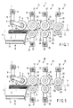
- FIG. 1 shows a schematic construction of a paper sheet separation and transfer apparatus 1 (hereinafter, simply referred to as a separation and transfer apparatus 1) according to the present invention.
- the separation and transfer apparatus 1 has a housing 2 which contains a plurality of stacked paper sheets P.
- a take-out roller (take-out-unit) 3 is provided at the position contacting a paper sheet P1 at one end of the stack of paper sheets P contained in the housing 2.
- Each roller shown in FIG. 1 has two rollers separated from each other in the axial direction.
- the take-out roller 3 is fixed to the rotary shaft through a one-way clutch 4, and the rotary shaft is fixed to the front end of a press arm 5.
- the rotary shaft of a press motor 6 is fixed to the base end of the press arm 5.
- the press arm 5 is swung by driving the press motor 6, and the take-out roller 3 is pressed to the paper sheet P1 at one end of the stack.
- the press arm 5 and press motor 6 function as a press mechanism of the present invention.
- a torque control motor is adopted for the press motor 6, and the pressing force of the take-out roller 3 to the paper sheet P1 can be changed optionally.
- the take-out roller 3 is freely rotatable in the arrow direction (the forward direction) in the drawing by the action of one-way clutch 4. Therefore, when transferring the paper sheet P in the arrow T direction (forward) in the drawing, the take-out roller 3 rotates together with the paper sheet P, and does not generate a reverse force disturbing the transfer of the paper sheet P, that is, a force along the tangential direction of the take-out roller (hereinafter, simply referred to as a tangential force).
- a take-out motor 9 is connected to the rotary shaft of the take-out roller 3 through a plurality of pulleys 7 and timing belts 8. Namely, by driving the take-out motor 9, the take-out roller 3 is rotated in the arrow direction in the drawing.
- a position control motor is adopted for the take-out motor 9, and the rotation speed, direction and amount (angle) of the take-out roller 9 can be controlled optionally.
- a backup plate 10 is provided to move a plurality of paper sheets P in the stack by pressing a paper sheet P at the other end of the stack, and to supply a paper sheet P1 at one end of the stack to a predetermined take-out position.
- the backup plate 10 is urged in the stacking direction by an actuator described later.
- a guide member 11 is provided at the position adjacent to the housing 2, or the position opposite to the front end of the take-out direction of a plurality of paper sheets P.
- the guide member 11 is bent toward the nip of a first separation unit described later, and functions to guide the front end of each paper P in the transfer direction to the nip.
- a first separation unit 13, a second separation unit 14 and a pull-out unit 15 are sequentially arranged close to each other along the transfer direction T.
- the first separation unit 13 has a first feed roller 16 which contacts the paper sheet P taken out onto the transfer path 12 and rotates forward along the transfer direction T, and a first separation roller 17 which is arranged opposite to the first feed roller 16 through the transfer path 12.
- the first separation roller 17 is pressed by a predetermined pressure to the first feed roller 16 in the state that no paper sheet P exists on the transfer path 12.
- the first feed roller 16 is arranged on the same side as the take-out roller 3 against the transfer path 12, that is, the upper side of the transfer path 12 in the drawing.
- the first feed roller 16 is attached to the rotary shaft through a one-way clutch 18. Therefore, when the paper sheet P is transferred in the arrow T direction along the transfer path 12, the first feed roller 16 rotates freely forward together with the paper sheet P, and does not generate a force (a tangential force) in the direction of disturbing the transfer of the paper sheet P.
- a first feed motor 21 is connected to the rotary shaft of the first feed roller 16 through a plurality of pulleys 19 and timing belts 20. Namely, by driving the first feed motor 21, the first feed roller 16 is rotated.
- a position control motor is adopted for the first feed motor 21, and the rotation speed, direction and amount (angle) of the first feed roller 16 can be controlled optionally.
- a first separation motor 24 is connected through a plurality of pulleys 22 and timing belts 23.
- the first separation motor 24 gives the first separation roller 17 a force in the direction to rotate the first separation roller 17 in the arrow direction in the drawing (the reverse direction).
- a torque control motor is adopted for the first separation motor 24, and a reverse separating force given by the first separation motor 24 to the first separation roller 17, that is, a separating force given by the first separation roller 17 to the paper sheet P in the tangential direction (hereinafter, sometimes referred to as a separation tangential force) can be changed optionally.
- a separation force given by the first separation motor 24 to the first separation roller 17 is set to the degree that the first separation roller 17 rotates forward together with the first feed roller 16, in the state that there is no paper sheet P to transfer on the transfer path 12, or the state that one paper sheet P is transferred.
- the first separation motor 24 tries to rotate the first separation roller 17 in the reverse direction, when no paper sheet P exists in the nip 13a in the space to the first feed roller 16, or when one paper sheet P exists, the first separation roller 17 is rotated forward.
- the first separation roller 17 gives a separating force (a separating tangential force) reverse to the direction T to the second and subsequent paper sheets P taken out together with the first paper sheet P1 in being overlapped therewith, and the second and subsequent paper sheets P are separated from the first paper sheet P1.
- the first separation roller 17 rotates together with the first paper sheet P1, and the first paper sheet P1 passes through the first separation unit 13.
- the second separation unit 14 provided on the downstream side of the first separation unit 13 along the paper sheet transfer direction T has the same structure as the first separation unit 13.
- the same reference numerals are given to the components having the similar functions, and detailed explanation will be omitted.
- different reference numerals are given to specific components.
- the second separation unit 14 has a second feed roller 25 driven and rotated by a second feed motor 27, and a second separation roller 26 given a separation force by a second separation motor 28.
- a position control motor is adopted for the second feed roller 27, and a torque control motor is adopted for the second separation motor 28.
- the second separation unit 14 functions to separate a plurality of paper sheets which are fed overlapped without being separated by the first separation unit 13.
- the pull-out unit 15 provided on the downstream side of the second separation unit 14 along the transfer direction T has a pull-out roller 29 and a pinch roller 30.
- the pull-out roller 29 is provided on the same side as the take-out roller 3 against the transfer path 12 (the upper side in the drawing).
- the pinch roller 30 is pressed by a predetermined pressure to the pull-out roller 29 through the transfer path 12.
- a pull-out motor 33 is connected to the rotary shaft of the pull-out roller 29 through a plurality of pulleys 31 and timing belts 32. Namely, by driving the pull-out motor 33, the pull-out roller 29 is rotted in the arrow direction in the drawing.
- a position control motor is adopted for the pull-out motor 33, and the rotation speed and amount (angle) of the pull-out roller 29 can be controlled optionally.
- a first sensor 34 (a first detector) and a second sensor 35 (a second detector) are provided on the transfer path 12.
- Each sensor 34 and 35 has a light emitting part and a light receiving part, detects the passage of the paper sheet P by the fact that the paper sheet P interrupts the light from the light emitting part to the light receiving part.
- the first sensor 34 is provided at the position where the light crosses the transfer path 12 between the nip 13a located between the first feed roller 16 and first separation roller 17 (hereinafter, called the nip 13a of the first separation unit 13) and a nip 14a located between the second feed roller 25 and second separation roller 26 (hereinafter, called the nip 14a of the second separation unit 14).
- the second sensor 35 is provided at the position where the light crosses the transfer path 12 between the nip 14a of the second separation unit 14 and a nip 15a located between the pull-out roller 29 and pinch roller 30 (hereinafter, called the nip 15a of the pull-out unit 15).
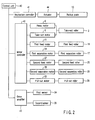
- FIG. 2 shows a block diagram of a control system which controls the operation of the separation and transfer apparatus 1 with the above structure.
- the separation and transfer apparatus 1 has a control unit 40 which controls the apparatus.
- the control unit 40 is connected with a mechanism controller 41, a motor controller 42 and a drive amplifier 43.
- the mechanism controller 41 is connected with an actuator 44 of the aforementioned backup plate 10.
- the motor controller 42 is connected with the press motor 6 which presses the take-out roller 3 to the paper sheet P1, the take-out motor 9 which rotates the take-out roller 3, a first feed motor 21 which rotates the first feed roller 16, a first separation motor 24 which gives the first separation roller 17 a reverse separation force, the second feed motor 27 which rotates the second feed roller 25, the second separation motor 28 which gives the second separation roller 26 a reverse separation force, and a pull-out motor 33 which rotates the pull-out roller 29.
- the drive amplifier 43 is connected with the aforementioned first sensor 34 and second sensor 35. Thus, the output signals from the sensors 34 and 35 are sent to the control unit 40.
- the control unit 40 controls the motor controller 42, drives the press motor 6, first feed motor 21, first separation motor 24, second feed motor 27, second separation motor 28 and pull-out motor 33, presses the take-out roller 3 to the paper sheet P1 at one end of the stack by a predetermined pressure, rotates forward the first feed roller 16, second feed roller 25 and pull-out roller 29 at a predetermined speed, and gives a predetermined separation torque to the first separation roller 17 and second separation roller 26 (Step 1).
- the first separation roller 17 rotates together with the first feed roller 16, and the second separation roller 26 rotates together with the second feed roller 25.
- control unit 40 controls the motor controller 42, drives the take-out motor 9 and rotates the take-out roller 3 forward at a predetermined speed, and takes out the paper sheet P1 at one end of the stack contacted and rotated by the take-out roller 3 onto the transfer path 12 (Step 2).
- the second and subsequent paper sheets may be taken out overlapped together with the first paper sheet P1 onto the transfer path 12.
- the motor controller 42 controls the rotation speeds of the motors 9, 21, 27 and 33, so that the peripheral speeds of the take-out roller 3, first feed roller 16, second feed roller 25 and pull-out roller 29 become V1, V2, V3 and V4, respectively.
- the motor controller 42 controls the rotation speeds of the rollers 3, 16, 25 and 29, so that the peripheral speeds V1 V2, V3 and V4 of the rollers satisfy the following expression: V ⁇ 1 ⁇ V ⁇ 2 ⁇ V ⁇ 3 ⁇ V ⁇ 4
- Step 3 When a certain time passes after detecting that the front end in the transfer direction of the paper sheet P1 taken out onto the transfer path 12 in step 2 has reached the first sensor 34 by passing through the nip 13a of the first separation unit 13 (Step 3; YES), the control unit 40 decelerates the take-out motor 9 and first feed motor 21, and decelerates the peripheral speeds of the take-out roller 3 and first feed roller 16 (Step 4). After the deceleration, the peripheral speeds V1' and V2' of the take-out roller 3 and feed roller 16 satisfy the following expression: V ⁇ 1 ′ ⁇ V ⁇ 2 ′ ⁇ V ⁇ 2
- the above certain time is the time from the arrival of the front end in the transfer direction of the paper sheet P1 at the first sensor 34 to the arrival at the nip 14a of the second separation unit 14, that is, the time determined by the peripheral speed of the first feed roller 16 and the distance from the position where the first sensor 34 crosses the transfer path 12 to the nip 14a of the second separation unit 14.
- the control unit 40 decelerates the take-out motor 9 and first feed motor 21 at the timing that the front end of the paper sheet P1 in the transfer direction reaches the nip 14a of the second separation unit 14.
- decelerate mentioned here and the term “decelerate” described in the Claims indicate the control to decelerate the roller rotating forward, and include all states from stop of the roller after deceleration to start of rotation in the reverse direction.
- control unit 40 detects that the rear end of the paper sheet P1 in the transfer direction passes through the first sensor 34 (Step 5; YES), and accelerates the take-out motor 9 and first feed motor 21 to return the peripheral speeds of the take-out roller 3 and first feed roller 16 to V1 and V2, respectively (Step 6). Then, the control unit 40 repeats the control of steps 2 to 6 until all paper sheets P contained in the housing 2 are taken out (Step 7: NO).
- control unit 40 monitors the time that the paper sheet P passes through the first sensor 34, while executing the control in the above steps 2 to 6, and when the passing time becomes longer than a certain predetermined value continuously over a predetermined numbers of time, the control unit 40 judges that there is a possibility that the overlapped feed of the paper sheet P occurs frequently exceeding the separating capacity in the first separation unit 13, and controls the press motor 6 to decrease the pressing force of the take-out roller 3 to the paper sheet P.
- the peripheral speeds of the take-out roller 3 and first feed roller 16 are "decelerated” at the time when the front end in the transfer direction of the paper sheet P1 taken out onto the transfer path 12 reaches the nip 14a of the second separation unit 14, and if there is second and subsequent paper sheets taken out together with the paper sheet P1, it is possible to prevent a defect of causing a wrinkle in the paper sheet P on and after the second sheet during the separating operation in the second separation unit 14.
- the peripheral speed of the first feed roller 16 which feeds forward the rear end of the second paper sheet P2 can be delayed at least, decreasing the possibility of buckling the second paper sheet P2 between the nips 13a and 14a.
- the term “decelerate” mentioned here includes “stop” and “reverse”, and for example, when the paper sheet P is a relatively flimsy bill, it is possible to prevent substantially a defect of causing a wrinkle in the second paper sheet P2 by "stopping" the take-out roller 3 and “reversing" the first feed roller 16 to meet the peripheral speed of the second separation roller 26.
- FIG. 4 is a flowchart showing a second operation example, in which the outputs of the first and second sensors 34 and 35 are monitored, the output signals of two sensors 34 and 35 are ored, and two rollers 3 and 16 are "decelerated".
- This second operation example is the same as the aforementioned first operation example except that the processing of step 5 is different.
- the control unit 40 monitors the output of the first sensor 34 and detects that the rear end of the first paper sheet P1 in the transfer direction passes, and monitors the output of the second sensor 35 and detects that the rear end of the first paper sheet P1 in the transfer direction passes.
- the control unit 40 return the peripheral speeds of the rollers 3 and 16.
- control unit 40 for example, when the second paper sheet P2 is taken out together with the first paper sheet P1 and these two overlapped sheets are not separated by the first separation unit 13 but separated by the second separation unit 14, the control unit 40 "decelerates" continuously two rollers 3 and 16 until the rear end of the second paper sheet P2 in the transfer direction passes through the first sensor 34 in the first operation example, but in the second operation example, the peripheral speeds of the rollers 3 and 16 can be returned to the original speed at the time when the second sensor 35 detects the passage of the rear end of the first paper sheet P1 in the transfer direction. Namely, in this case, the time of "decelerating" the two rollers 3 and 16 can be reduced by adopting the second operation example.
- FIG. 5 shows a schematic construction of a separation and transfer apparatus 50 according to a second embodiment of the present invention.
- the first and second separation motors 24 and 28 contain encoders 51 and 52 (state detection unit), respectively.
- the separation and transfer apparatus 50 has the same structure as the aforementioned separation and transfer apparatus 1 except that the encoders 51 and 52 are used instead of the first and second sensors 34 and 35.
- the same reference numerals are given to the components having the same functions as in the separation and transfer apparatus 1, and detailed explanation of these components will be omitted.
- the encoder 51 contained in the first separation motor 24 detects the rotation speed of the first separation roller 17, and the encoder 52 contained in the second separation motor 28 detects the rotation speed of the second separation roller 26.
- the output ends of two encoders 51 and 52 are connected to the control unit 40. In other words, in this embodiment, the control unit 40 always monitors the rotation speeds of the first and second separation rollers 17 and 26 through the encoders 51 and 52.
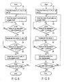
- FIG. 6 shows a flowchart for explaining a third operation example of the separation and transfer apparatus 50 with the above structure.
- This third operation example is basically the same as the first operation example except that the state of the paper sheet P is detected by the encoder 52.
- the control unit 40 monitors the output of the encoder 52 contained in the second separation motor 28 (Step 3), regards the drop of the rotation speed of the second separation roller 26 as a trigger (Step 3; YES), "decelerates” the take-out motor 9 and first feed motor 21, and “decelerates” the peripheral speeds of the take-out roller 3 and first feed roller 16 (Step 4).
- the term “decelerate” mentioned here includes “stop” and "reverse” as in the first embodiment.
- FIG. 7 shows changes with time of the rotation speed of the second separation roller 26 in the state rotated together with the second feed roller 25.
- the rotation speed of the second separation roller 26 is changed with time as shown in FIG. 8 . Namely, by monitoring the changes in the rotation speed of the second separation roller 26 through the encoder 52, it is possible to detect the state of the paper sheet P passing through the nip 14a of the second separation unit 14.
- Step 5 the control unit 40 regards the return of the rotation speed of the second separation roller 26 to the original speed (the arrow A in FIG. 8 ) as a trigger (Step 5; YES), judges that the first and second paper sheets P1 and P2 are separated, and accelerates the take-out motor 9 and first feed motor 21 so as to return the peripheral speeds of the take-out roller 3 and first feed roller 16 to V1 and V2, respectively (Step 6).
- the control unit 40 repeats the controls of steps 2 to 6 until all paper sheets P contained in the housing 2 are taken out (Step 7; NO).
- Step 3 When the rotation speed of the second separation roller 26 is lowered (Step 3; YES), the control unit 40 controls the first separation motor 24 to reduce the separation force given to the first separation roller 17. Namely, when the rotation speed of the second separation roller 26 is lowered as described above, the separation of the paper sheet P2 in the second separation unit 14 can be judged, and the separating operation in the first separation unit 13 becomes basically unnecessary.
- Step 3 when the rotation speed of the second separation roller 26 is lowered (Step 3; YES), the control unit 40 controls the press motor 6 to decrease the pressing force of the take-out roller 3 on the paper sheet P2.
- the forward force (tangential force) given to the separated paper sheet P2 can be decreased further, and the paper sheet P2 can be easily returned in the reverse direction.
- the control unit 40 regards the return of the rotation speed of the second separation roller 26 to the original speed as a trigger (Step 5; YES), judges that the separating operation is finished, returns the separation force given to the first separation roller 17 to the original value, and returns the pressing force of the take-out roller 3 to the paper sheet P to the original value.
- the separation and transfer unit 50 By operating the separation and transfer unit 50 according to the third operation example as explained above, the same effect as the first operation example can be obtained, and the state of the paper sheet P in the second separation unit 14 can be grasped more exactly, enabling more reliable separation and transfer.
- FIG. 9 is a flowchart showing a fourth operation example for preventing a buckle of the paper sheet P between the take-out roller 3 and nip 13a.
- the control unit 40 regards the drop of the rotation speed of the first separation roller 17 of the first separation unit 13 as a trigger (Step 3; YES), and controls the take-out motor 9 to "decelerate” the take-out roller 3 (Step 4).
- the term “deceleration” includes "stop” and "reverse”.
- the control unit 40 regards the return of the rotation speed of the first separation roller 17 to the original speed as a trigger after the end of the separating operation in the first separation unit 13 (Step 5; YES), and controls the take-out motor 9 to return the peripheral speed of the take-out roller 3 to the original speed (Step 6).
- the control unit 40 repeats the control of steps 2 to 6 until all paper sheets P contained in the housing 2 are taken out (Step 7; NO).
- Step 3 When the rotation speed of the second separation roller 26 is lowered (Step 3; YES), the control unit 40 controls the first separation motor 24 to reduce the separation force given to the first separation roller 17. Namely, when the rotation speed of the second separation roller 26 is lowered as described above, the separation of the paper sheet P2 in the second separation unit 14 can be judged, and the separating operation in the first separation unit 13 becomes basically unnecessary.
- the control unit 40 controls the first separation motor 24 and reduces the separating force given to the first separation roller 17. Namely, when the rotation speed of the first separation roller 17 is lowered, the rotation speed of the take-out roller 3 is decelerated, the pressing force of the take-out roller 3 is reduced, and the paper sheet can be easily separated. Therefore, the paper sheet is prevented from being moved back excessively, by reducing the separating force of the first separation roller 17.
- Step 3; YES When the rotation speed of the first separation roller 17 is lowered (Step 3; YES), the control unit 40 controls the press motor 6 so as to lower the pressing force of the take-out roller 3 on the paper sheet P, and makes it easy to return the paper sheet P2 in the reverse direction. Further, when the rotation speed of the first separation roller 17 is returned to the original speed (Step 5; YES), the control unit 40 controls the press motor 6 so as to return the pressing force of the take-out roller 3 to the original value.
- the take-out roller 3 is "decelerated” and the pressing force of the take-out roller 3 is lowered at the time when the separating operation is started in the first separation unit 13, the second paper sheet P2 taken out together with the first paper sheet P1 can be easily returned, and the buckling of the paper sheet P2 between the nip of the take-out roller 3 and nip 13a of the first separation unit 13 can be prevented.
- the overlapped state of paper sheet P is detected by using the sensors 34 and 35 or encoders 51 and 52.
- the invention is not to be limited to this.
- the overlapped state of paper sheet P may be detected by detecting the thickness of paper sheet P.
- the second embodiment uses the encoders 51 and 52 of the type incorporated in the separation motors 24 and 28, but an external encoder may be used. Or, it is permitted to use a tachogenerator for detecting the rotation speed.
- the stacking direction of the paper sheet P is shown vertical in FIG. 1 and FIG. 5 , but the horizontal direction is permitted, and the stacking is not to be limited to the gravity direction.
- the paper sheets P are taken out one by one onto the transfer path 12 by contacting and rotating the take-out roller 3 with the stacked paper sheets P, but a take-out belt can be used instead of the take-out roller 3. It is also permitted to use a pair of pull-out belts instead of the pull-out roller 29 and pinch roller 30.
Landscapes
- Engineering & Computer Science (AREA)
- Mechanical Engineering (AREA)
- Sheets, Magazines, And Separation Thereof (AREA)
- Controlling Sheets Or Webs (AREA)
Claims (10)
- Papierbogentrennungs- und transportvorrichtung, aufweisend:eine Entnahmeeinheit (3), die eingerichtet ist, zu rotieren und einen Papierbogen an einem Ende eines Stapels aus mehreren Papierbögen zu kontaktieren, und den Papierbogen auf einen Transportweg herauszunehmen;eine erste Trenneinheit (13) mit einer ersten Zuführrolle (16), die eingerichtet ist, den auf den Transportweg herausgenommenen Papierbogen zu kontaktieren und vorwärts zu rotieren, und eine erste Trennrolle (117), die über den Transportweg hinweg gegen die erste Zuführrolle gedrückt ist, und eingerichtet ist, durch Ausüben einer entgegengesetzten Trennkraft zweite und weitere Papierbögen, die zusammen mit dem ersten Papierbogen entnommen wurden, zu trennen; undeine zweite Trenneinheit (14) mit einer zweiten Zuführrolle (25), die eingerichtet ist, den Papierbogen, der die erste Trenneinheit (13) passiert hat, zu kontaktieren und vorwärts zu rotieren, sowie eine zweite Trennrolle (26), die über den Transportweg hinweg gegen die zweite Zuführrolle gedrückt ist, und eingerichtet ist, durch Ausüben einer entgegengesetzten Trennkraft zweite und weitere Papierbögen, die zusammen mit dem ersten Papierbogen entnommen wurden, zu trennen;gekennzeichnet durch:eine Zustandserfassungseinheit (52), die eingerichtet ist, den Zustand zu erfassen, dass zwischen der zweiten Zuführrolle (25) und der zweiten Trennrolle (26) mehrere Papierbögen vorhanden sind; undeine Steuereinheit (40), die eingerichtet ist, die Umlaufgeschwindigkeit der ersten Zuführrolle (16) zu drosseln, wenn die Zustandserfassungseinheit (52) diesen Zustand erfasst, ohne die Umlaufgeschwindigkeit der zweiten Zuführrolle (25) zu ändern;wobei die Zustandserfassungseinheit (52), eingerichtet ist, die Drehgeschwindigkeit der zweiten Trennrolle (26) zu erfassen, und den Zustand auf Basis dieser Erfassung zu erfassen.
- Papierbogentrennungs- und transportvorrichtung gemäß Anspruch 1, dadurch gekennzeichnet, dass die Steuereinheit (40) eingerichtet ist, die erste Zuführrolle (16) zu stoppen, wenn die Zustandserfassungseinheit (52) den Zustand erfasst.
- Papierbogentrennungs- und transportvorrichtung gemäß Anspruch 1, dadurch gekennzeichnet, dass die Steuereinheit (40) eingerichtet ist, die erste Zuführrolle (16) in die entgegengesetzte Richtung zu drehen, wenn die Zustandserfassungseinheit (52) den Zustand erfasst.
- Papierbogentrennungs- und transportvorrichtung gemäß einem der Ansprüche 1 bis 3, dadurch gekennzeichnet, dass die Steuereinheit (40) eingerichtet ist, die Umlaufgeschwindigkeit der ersten Zuführrolle (16) auf die ursprüngliche Geschwindigkeit zurückzustellen, wenn der Zustand zurückgesetzt wird.
- Papierbogentrennungs- und transportvorrichtung gemäß Anspruch 1, dadurch gekennzeichnet, dass die Steuereinheit (40) eingerichtet ist, die Umlaufgeschwindigkeit der Entnahmeeinheit (3) zu drosseln, wenn die Zustandserfassungseinheit (52) den Zustand erfasst.
- Papierbogentrennungs- und transportvorrichtung gemäß Anspruch 5, dadurch gekennzeichnet, dass die Steuereinheit (40) eingerichtet ist, die Umlaufgeschwindigkeit der Entnahmeeinheit (3) auf die ursprüngliche Geschwindigkeit zurückzustellen, wenn der Zustand zurückgesetzt wird.
- Papierbogentrennungs- und transportvorrichtung gemäß Anspruch 5 oder 6, dadurch gekennzeichnet, dass sie ferner einen Andruckmechanismus (6) aufweist, der eingerichtet ist, die Entnahmeeinheit (3) an einen Papierbogen anzudrücken, wobei die Steuereinheit (40) eingerichtet ist, den Andruckmechanismus (6) derart anzusteuern, dass die Andruckkraft der Entnahmeeinheit (3) verringert wird, wenn die Zustandserfassungseinheit (52) den Zustand erfasst.
- Papierbogentrennungs- und transportvorrichtung gemäß Anspruch 7, dadurch gekennzeichnet, dass die Steuereinheit (40) eingerichtet ist, den Andruckmechanismus (6) derart anzusteuern, dass die Andruckkraft der Entnahmeeinheit (3) auf die ursprüngliche Kraft zurückgestellt wird, wenn der Zustand zurückgesetzt wird.
- Papierbogentrennungs- und transportvorrichtung gemäß Anspruch 1, dadurch gekennzeichnet, dass die Steuereinheit (40) eingerichtet ist, die Trennkraft der ersten Trennrolle (17) zu verringern, wenn die Zustandserfassungseinheit (52) den Zustand erfasst.
- Papierbogentrennungs- und transportvorrichtung gemäß Anspruch 9, dadurch gekennzeichnet, dass die Steuereinheit (40) eingerichtet ist, die Trennkraft der ersten Trennrolle (17) auf die ursprüngliche Kraft zurückzustellen, wenn der Zustand zurückgesetzt wird.
Applications Claiming Priority (2)
| Application Number | Priority Date | Filing Date | Title |
|---|---|---|---|
| JP2003311594A JP4184904B2 (ja) | 2003-09-03 | 2003-09-03 | 紙葉類分離搬送装置 |
| EP04021014.8A EP1512649B1 (de) | 2003-09-03 | 2004-09-03 | Papierbogenaufnahme- und Übertragungsgerät |
Related Parent Applications (2)
| Application Number | Title | Priority Date | Filing Date |
|---|---|---|---|
| EP04021014.8A Division EP1512649B1 (de) | 2003-09-03 | 2004-09-03 | Papierbogenaufnahme- und Übertragungsgerät |
| EP04021014.8A Division-Into EP1512649B1 (de) | 2003-09-03 | 2004-09-03 | Papierbogenaufnahme- und Übertragungsgerät |
Publications (2)
| Publication Number | Publication Date |
|---|---|
| EP2116492A1 EP2116492A1 (de) | 2009-11-11 |
| EP2116492B1 true EP2116492B1 (de) | 2014-05-07 |
Family
ID=34131843
Family Applications (6)
| Application Number | Title | Priority Date | Filing Date |
|---|---|---|---|
| EP09011067.7A Expired - Lifetime EP2116493B9 (de) | 2003-09-03 | 2004-09-03 | Papierbogenaufnahme- und Übertragungsgerät |
| EP10185786.0A Expired - Lifetime EP2275369B1 (de) | 2003-09-03 | 2004-09-03 | Papierbogenaufnahme- und Übertragungsgerät |
| EP10185746.4A Expired - Lifetime EP2275368B1 (de) | 2003-09-03 | 2004-09-03 | Papierbogenaufnahme- und Übertragungsgerät |
| EP04021014.8A Expired - Lifetime EP1512649B1 (de) | 2003-09-03 | 2004-09-03 | Papierbogenaufnahme- und Übertragungsgerät |
| EP11169727.2A Expired - Lifetime EP2371747B1 (de) | 2003-09-03 | 2004-09-03 | Papiertrennungs- und Transportvorrichtung |
| EP09011066.9A Expired - Lifetime EP2116492B1 (de) | 2003-09-03 | 2004-09-03 | Papierbogenaufnahme- und Übertragungsgerät |
Family Applications Before (5)
| Application Number | Title | Priority Date | Filing Date |
|---|---|---|---|
| EP09011067.7A Expired - Lifetime EP2116493B9 (de) | 2003-09-03 | 2004-09-03 | Papierbogenaufnahme- und Übertragungsgerät |
| EP10185786.0A Expired - Lifetime EP2275369B1 (de) | 2003-09-03 | 2004-09-03 | Papierbogenaufnahme- und Übertragungsgerät |
| EP10185746.4A Expired - Lifetime EP2275368B1 (de) | 2003-09-03 | 2004-09-03 | Papierbogenaufnahme- und Übertragungsgerät |
| EP04021014.8A Expired - Lifetime EP1512649B1 (de) | 2003-09-03 | 2004-09-03 | Papierbogenaufnahme- und Übertragungsgerät |
| EP11169727.2A Expired - Lifetime EP2371747B1 (de) | 2003-09-03 | 2004-09-03 | Papiertrennungs- und Transportvorrichtung |
Country Status (4)
| Country | Link |
|---|---|
| US (3) | US7270326B2 (de) |
| EP (6) | EP2116493B9 (de) |
| JP (1) | JP4184904B2 (de) |
| CN (1) | CN1315708C (de) |
Families Citing this family (65)
| Publication number | Priority date | Publication date | Assignee | Title |
|---|---|---|---|---|
| KR100572859B1 (ko) * | 2003-12-26 | 2006-04-24 | 엘지엔시스(주) | 매체자동지급기의 매체이송방법 및 장치 |
| DE102004037422B3 (de) * | 2004-07-30 | 2006-03-09 | Siemens Ag | Vereinzelungsstrecke für überlappte flache Sendungen in stehender Position |
| US20070001389A1 (en) * | 2005-06-17 | 2007-01-04 | Honeywell International Inc. | Printer medium or currency thickness / double sheet detection method |
| US7455286B2 (en) * | 2005-06-28 | 2008-11-25 | Hewlett-Packard Development Company, L.P. | Sheet separation using two torque motors |
| JP2007062988A (ja) * | 2005-09-01 | 2007-03-15 | Canon Inc | シート搬送装置と画像形成装置 |
| SE531523C2 (sv) * | 2005-12-01 | 2009-05-05 | De La Rue Cash Systems Ab | Separeringsanordning |
| JP4660445B2 (ja) * | 2006-09-08 | 2011-03-30 | 株式会社東芝 | 紙葉類処理装置、および紙葉類処理方法 |
| US7604230B2 (en) * | 2006-04-28 | 2009-10-20 | Pitney Bowes Inc. | Method of providing multiple separation modes in a feeder |
| JP4822984B2 (ja) * | 2006-08-23 | 2011-11-24 | キヤノン株式会社 | 記録媒体の搬送装置、搬送方法、および記録装置 |
| WO2008032446A1 (fr) | 2006-09-14 | 2008-03-20 | Kabushiki Kaisha Toshiba | Dispositif d'extraction de feuilles, dispositif de manipulation de feuilles et procédé d'extraction de feuilles |
| JP2008094510A (ja) * | 2006-10-06 | 2008-04-24 | Seiko Epson Corp | 給送装置、記録装置、液体噴射装置および給送方法 |
| JP4306732B2 (ja) * | 2007-01-26 | 2009-08-05 | シャープ株式会社 | シート搬送装置、それを備えてなる自動原稿送り装置および画像形成装置 |
| KR20080070994A (ko) * | 2007-01-29 | 2008-08-01 | 삼성전자주식회사 | 잉크젯 화상형성장치 및 그 제어방법 |
| US7810811B2 (en) * | 2007-03-30 | 2010-10-12 | Canon Kabushiki Kaisha | Sheet conveying apparatus and image forming apparatus |
| US20080290584A1 (en) * | 2007-05-24 | 2008-11-27 | Ncr Corporation | Method of operating a document feeding mechanism to detect and recover from a multi-feed condition and an apparatus therefor |
| JP4862753B2 (ja) * | 2007-06-08 | 2012-01-25 | 富士ゼロックス株式会社 | 給紙装置及びこれを備えた画像形成装置 |
| DE102007033747A1 (de) * | 2007-07-19 | 2009-01-22 | Giesecke & Devrient Gmbh | Vorrichtung und Verfahren für die Überwachung der Vereinzelung von Blattgut |
| JP2009067513A (ja) * | 2007-09-12 | 2009-04-02 | Hitachi Omron Terminal Solutions Corp | 紙葉類集積装置並びに紙葉類集積装置の制御方法及び制御プログラム |
| DE102008014676A1 (de) * | 2008-02-28 | 2009-09-10 | Siemens Aktiengesellschaft | Verfahren und Vorrichtung zum Vereinzeln von Gegenständen |
| EP2096056B1 (de) * | 2008-02-28 | 2017-08-16 | Siemens Aktiengesellschaft | Verfahren und Vorrichtung zum Vereinzeln von Gegenständen |
| JP4706741B2 (ja) * | 2008-09-09 | 2011-06-22 | ブラザー工業株式会社 | 原点検出装置、シート搬送装置、及び画像記録装置 |
| JP2010095367A (ja) * | 2008-10-17 | 2010-04-30 | Pfu Ltd | シート給送装置及び媒体検出方法 |
| FR2944268B1 (fr) * | 2009-04-09 | 2011-04-15 | Solystic | Dispositif d'alimentation d'objets plats avec un synchronisateur a plusieurs motorisations |
| TWI347894B (en) * | 2009-04-24 | 2011-09-01 | Primax Electronics Ltd | Method for controlling the spacing between any two documents on the front feeding path and a laminator having the same thereof |
| CN101891071B (zh) * | 2009-05-22 | 2012-09-05 | 致伸科技股份有限公司 | 馈纸间距的控制方法与应用该方法的薄片热叠合装置 |
| DE102009039067A1 (de) * | 2009-08-27 | 2011-03-10 | Siemens Aktiengesellschaft | Vorrichtung und Verfahren zum Vereinzeln von flachen Gegenständen mittels zweier seitlich versetzter Vereinzelern |
| DE102009039062A1 (de) * | 2009-08-27 | 2011-03-10 | Siemens Aktiengesellschaft | Vorrichtung und Verfahren zum Vereinzeln von flachen Gegenständen mittels zweier Vereinzeler und einem Längendetektor |
| JP5233947B2 (ja) * | 2009-10-09 | 2013-07-10 | 富士ゼロックス株式会社 | 搬送装置及び画像形成装置 |
| JP5485295B2 (ja) | 2009-12-21 | 2014-05-07 | 株式会社東芝 | 紙葉類処理装置および紙葉類処理方法 |
| JP5724356B2 (ja) * | 2010-01-19 | 2015-05-27 | 株式会社リコー | 搬送装置、画像形成装置およびプログラム |
| JP2011225370A (ja) * | 2010-03-30 | 2011-11-10 | Toshiba Corp | 紙葉類処理装置および紙葉類処理方法 |
| JP2012001301A (ja) * | 2010-06-15 | 2012-01-05 | Ricoh Co Ltd | 自動原稿搬送装置およびこれを備えた画像形成装置 |
| DE102010034445A1 (de) * | 2010-08-16 | 2012-02-16 | Giesecke & Devrient Gmbh | Vorrichtung für die Überwachung der Vereinzelung von Blattgut |
| DE102010052988A1 (de) * | 2010-11-30 | 2012-05-31 | Giesecke & Devrient Gmbh | Vorrichtung für die Vereinzelung von Blattgut |
| US8280263B2 (en) * | 2011-01-31 | 2012-10-02 | Xerox Corporation | Multi-feed detection and control system |
| JP5749513B2 (ja) * | 2011-02-10 | 2015-07-15 | グローリー株式会社 | 紙葉類分離搬送装置 |
| JP5850623B2 (ja) * | 2011-02-10 | 2016-02-03 | グローリー株式会社 | 紙葉類分離搬送装置 |
| DE102011000794A1 (de) * | 2011-02-17 | 2012-08-23 | Wincor Nixdorf International Gmbh | Verfahren zum Vereinzeln eines Wertscheinstapels |
| CN102760325B (zh) | 2011-04-29 | 2014-11-05 | 山东新北洋信息技术股份有限公司 | 纸币处理装置及纸币输送状态检测方法 |
| US8777220B2 (en) * | 2011-06-28 | 2014-07-15 | Kabushiki Kaisha Toshiba | Sheet feeding device and sheet feeding method |
| CN102320487A (zh) * | 2011-08-31 | 2012-01-18 | 深圳市新达通科技股份有限公司 | 等角度单向旋转机构 |
| US8651652B2 (en) * | 2012-04-27 | 2014-02-18 | Hewlett-Packard Development Company, L.P. | Pivotable ink cartridge platform for printer device |
| CN102887376B (zh) * | 2012-10-22 | 2015-08-26 | 广州广电运通金融电子股份有限公司 | 一种纸张类介质分离装置 |
| WO2014097604A1 (ja) | 2012-12-17 | 2014-06-26 | キヤノン電子株式会社 | シート材取込装置、シート材搬送装置、画像読取装置および画像形成装置 |
| JP5751721B2 (ja) * | 2013-01-25 | 2015-07-22 | 京セラドキュメントソリューションズ株式会社 | シート搬送装置、原稿搬送装置および画像形成装置 |
| JP6478451B2 (ja) * | 2013-09-25 | 2019-03-06 | キヤノン株式会社 | シート給送装置及び画像形成装置 |
| TW201522085A (zh) * | 2013-12-12 | 2015-06-16 | Foxlink Image Tech Co Ltd | 防夾紙自動饋紙器 |
| CN104021613A (zh) * | 2014-04-30 | 2014-09-03 | 昆山古鳌电子机械有限公司 | 一种能够判别纸张类冠字号的纸张类集积装置 |
| JP6372223B2 (ja) * | 2014-07-28 | 2018-08-15 | 富士ゼロックス株式会社 | 記録シートの搬送装置及び画像読取装置 |
| CN105417223B (zh) * | 2014-09-10 | 2017-09-26 | 柯尼卡美能达办公系统研发(无锡)有限公司 | 图像形成装置及其供纸机构 |
| JP2016179886A (ja) * | 2015-03-24 | 2016-10-13 | 日本電気株式会社 | 郵便物の分離機構および分離方法 |
| TWI577569B (zh) * | 2015-08-11 | 2017-04-11 | 虹光精密工業股份有限公司 | 傳動組件及包括其之事務機 |
| JP6572674B2 (ja) * | 2015-08-17 | 2019-09-11 | ブラザー工業株式会社 | 画像読取装置 |
| CN105608748B (zh) * | 2015-10-21 | 2018-11-13 | 易程(苏州)电子科技股份有限公司 | 一种具有暂存区的磁票制票装置 |
| JP6223410B2 (ja) * | 2015-12-10 | 2017-11-01 | キヤノン株式会社 | 給送装置 |
| TWI624424B (zh) * | 2015-12-16 | 2018-05-21 | 理光股份有限公司 | 片材分離裝置、片材分離方法、程式、影像形成裝置及非暫時性電腦可讀取儲存媒體 |
| CN106097557A (zh) * | 2016-06-01 | 2016-11-09 | 武汉科技大学 | 一种纸币清分整理机 |
| JP7067276B2 (ja) * | 2018-05-31 | 2022-05-16 | セイコーエプソン株式会社 | 媒体給送装置 |
| CN110000838B (zh) * | 2019-04-02 | 2020-11-20 | 浙江特圣建材有限公司 | 一种具有自动上料功能的建筑板材加工设备 |
| CN110002254B (zh) * | 2019-04-19 | 2024-06-25 | 天津光电通信技术有限公司 | 一种办公设备用取纸分页机构 |
| JP7379855B2 (ja) * | 2019-04-22 | 2023-11-15 | 京セラドキュメントソリューションズ株式会社 | 給紙装置及び画像形成装置 |
| JP7456222B2 (ja) * | 2020-03-23 | 2024-03-27 | 株式会社リコー | 搬送装置および画像形成装置 |
| CN111348452A (zh) * | 2020-04-30 | 2020-06-30 | 惠东县三宏橡塑科技有限公司 | 一种橡胶发泡片材的自动装料机构 |
| CN112061746A (zh) * | 2020-08-01 | 2020-12-11 | 陕西大泽印务有限公司 | 一种插页线上书装置 |
| CN116835353B (zh) * | 2023-05-29 | 2025-11-28 | 苏州单多啦科技有限公司 | 一种上下滚轮分纸机构及其使用方法 |
Family Cites Families (26)
| Publication number | Priority date | Publication date | Assignee | Title |
|---|---|---|---|---|
| US4030722A (en) * | 1975-05-13 | 1977-06-21 | Pitney-Bowes, Inc. | Sheet-material separator and feeder system |
| US4030723A (en) | 1975-12-15 | 1977-06-21 | Pitney-Bowes, Inc. | Vacuum-controlled, sheet-material separator and feeder system |
| US4083555A (en) * | 1977-04-11 | 1978-04-11 | Pitney-Bowes, Inc. | Sheet-material separator and feeder system |
| US4203586A (en) * | 1978-06-28 | 1980-05-20 | Xerox Corporation | Multifeed detector |
| DE3029458A1 (de) * | 1980-08-02 | 1982-03-04 | Kleindienst Gmbh & Co Kg, 8900 Augsburg | Transport- und ausrichtvorrichtung zum vereinzeln von belegen, insbesondere datentraegern |
| JPS5912029A (ja) * | 1982-07-09 | 1984-01-21 | Canon Inc | 用紙の重送検出及び防止装置 |
| JPH0281845A (ja) * | 1988-06-14 | 1990-03-22 | Minolta Camera Co Ltd | 給紙装置 |
| JPH04371430A (ja) * | 1991-06-18 | 1992-12-24 | Mita Ind Co Ltd | 用紙搬送装置 |
| JPH06219600A (ja) * | 1992-11-26 | 1994-08-09 | Toshiba Corp | 自動原稿搬送装置 |
| JP3049978B2 (ja) * | 1992-12-07 | 2000-06-05 | ミノルタ株式会社 | 給紙装置 |
| JP2958395B2 (ja) | 1995-09-12 | 1999-10-06 | 富士ゼロックス株式会社 | 給紙装置 |
| JPH1087088A (ja) * | 1996-09-18 | 1998-04-07 | Mita Ind Co Ltd | 給紙装置 |
| JPH11255347A (ja) * | 1998-02-02 | 1999-09-21 | Princares Inc | 各種厚さのシ―ト或いはシ―ト状物に適合するボトムシ―トフィ―ダとそのフィ―ド経路 |
| JP2000044069A (ja) * | 1998-07-28 | 2000-02-15 | Casio Comput Co Ltd | 用紙分離装置およびそのプログラム記録媒体 |
| JP3661839B2 (ja) | 1999-08-17 | 2005-06-22 | 株式会社Pfu | 用紙分離装置及び光学式読取り装置 |
| TW477748B (en) * | 2000-02-18 | 2002-03-01 | Acer Peripherals Inc | Feeding paper system having taking paper and distributing paper mechanism |
| JP2001253573A (ja) * | 2000-03-15 | 2001-09-18 | Toshiba Corp | 紙葉類処理装置および紙葉類の取出装置 |
| JP2003012178A (ja) * | 2001-07-03 | 2003-01-15 | Toshiba Corp | 紙葉類分離搬送機構 |
| JP2003081463A (ja) * | 2001-09-12 | 2003-03-19 | Toshiba Corp | 紙葉類取出装置 |
| JP2003206054A (ja) * | 2002-01-17 | 2003-07-22 | Toshiba Corp | 紙葉類の重送検知装置 |
| JP3959328B2 (ja) | 2002-03-20 | 2007-08-15 | 株式会社東芝 | 紙葉類取出装置および紙葉類取出方法 |
| JP4077245B2 (ja) | 2002-05-28 | 2008-04-16 | 株式会社東芝 | 紙葉類取出装置 |
| JP4186666B2 (ja) * | 2003-03-24 | 2008-11-26 | 富士ゼロックス株式会社 | シートの重送状態判定装置およびシート搬送装置 |
| JP4364012B2 (ja) * | 2003-05-14 | 2009-11-11 | 株式会社東芝 | 紙葉類の重送検知装置、および重送検知方法 |
| JP4395085B2 (ja) * | 2005-02-07 | 2010-01-06 | 株式会社Pfu | シート給送装置 |
| US7588245B2 (en) * | 2005-11-03 | 2009-09-15 | Xerox Corporation | Friction retard sheet feeder |
-
2003
- 2003-09-03 JP JP2003311594A patent/JP4184904B2/ja not_active Expired - Fee Related
-
2004
- 2004-09-02 US US10/932,351 patent/US7270326B2/en not_active Expired - Lifetime
- 2004-09-03 EP EP09011067.7A patent/EP2116493B9/de not_active Expired - Lifetime
- 2004-09-03 EP EP10185786.0A patent/EP2275369B1/de not_active Expired - Lifetime
- 2004-09-03 EP EP10185746.4A patent/EP2275368B1/de not_active Expired - Lifetime
- 2004-09-03 EP EP04021014.8A patent/EP1512649B1/de not_active Expired - Lifetime
- 2004-09-03 EP EP11169727.2A patent/EP2371747B1/de not_active Expired - Lifetime
- 2004-09-03 EP EP09011066.9A patent/EP2116492B1/de not_active Expired - Lifetime
- 2004-09-03 CN CNB2004100752029A patent/CN1315708C/zh not_active Expired - Fee Related
-
2006
- 2006-12-07 US US11/634,947 patent/US7416180B2/en not_active Expired - Lifetime
-
2007
- 2007-05-03 US US11/797,449 patent/US7717416B2/en not_active Expired - Lifetime
Also Published As
| Publication number | Publication date |
|---|---|
| EP2116493B9 (de) | 2014-10-29 |
| EP2371747A1 (de) | 2011-10-05 |
| CN1315708C (zh) | 2007-05-16 |
| US7270326B2 (en) | 2007-09-18 |
| JP4184904B2 (ja) | 2008-11-19 |
| US7717416B2 (en) | 2010-05-18 |
| US7416180B2 (en) | 2008-08-26 |
| CN1590259A (zh) | 2005-03-09 |
| JP2005075630A (ja) | 2005-03-24 |
| EP2116493A1 (de) | 2009-11-11 |
| EP1512649A3 (de) | 2007-06-20 |
| EP2275369A1 (de) | 2011-01-19 |
| EP1512649B1 (de) | 2014-03-26 |
| EP2371747B1 (de) | 2014-04-23 |
| EP2275368B1 (de) | 2014-04-02 |
| US20070210506A1 (en) | 2007-09-13 |
| EP2275369B1 (de) | 2014-05-07 |
| US20050082739A1 (en) | 2005-04-21 |
| EP2116492A1 (de) | 2009-11-11 |
| EP2116493B1 (de) | 2014-06-25 |
| US20070085262A1 (en) | 2007-04-19 |
| EP1512649A2 (de) | 2005-03-09 |
| EP2275368A1 (de) | 2011-01-19 |
Similar Documents
| Publication | Publication Date | Title |
|---|---|---|
| EP2116492B1 (de) | Papierbogenaufnahme- und Übertragungsgerät | |
| EP0393589B1 (de) | Kontinuierliches Papierausgabegerät | |
| US6260840B1 (en) | Sheet feeding apparatus, image forming apparatus having the same and image reading apparatus having the same | |
| JP4395085B2 (ja) | シート給送装置 | |
| US6354584B1 (en) | Sheet feeding apparatus, image forming apparatus having the same and image reading apparatus having the same | |
| JPS58172136A (ja) | 紙葉類の分離給送装置 | |
| EP0942887B1 (de) | Blattzufuhrapparat | |
| JP3197029B2 (ja) | シート給送装置 | |
| US7806401B2 (en) | Medium feeding apparatus | |
| JP3968399B2 (ja) | 紙葉送り出し装置 | |
| JP2003176052A (ja) | シート搬送分離装置 | |
| JPH0331148A (ja) | 給紙装置 | |
| JP3446181B2 (ja) | 紙葉類分離繰り出し集積装置 | |
| JPH115640A (ja) | 給紙装置 | |
| JPH08157084A (ja) | 給紙装置 | |
| JP2007076833A (ja) | シート積載装置および画像形成装置 | |
| JPS6214448B2 (de) | ||
| JP2001039553A (ja) | 画像形成装置 | |
| JPS6357442A (ja) | 紙葉類の取出し装置 | |
| JP2011143987A (ja) | シート給送装置及び画像形成装置 |
Legal Events
| Date | Code | Title | Description |
|---|---|---|---|
| PUAI | Public reference made under article 153(3) epc to a published international application that has entered the european phase |
Free format text: ORIGINAL CODE: 0009012 |
|
| 17P | Request for examination filed |
Effective date: 20090828 |
|
| AC | Divisional application: reference to earlier application |
Ref document number: 1512649 Country of ref document: EP Kind code of ref document: P |
|
| AK | Designated contracting states |
Kind code of ref document: A1 Designated state(s): AT BE BG CH CY CZ DE DK EE ES FI FR GB GR HU IE IT LI LU MC NL PL PT RO SE SI SK TR |
|
| 17Q | First examination report despatched |
Effective date: 20100126 |
|
| RBV | Designated contracting states (corrected) |
Designated state(s): DE FR GB SE |
|
| RIC1 | Information provided on ipc code assigned before grant |
Ipc: B65H 3/06 20060101ALI20131101BHEP Ipc: B65H 3/52 20060101AFI20131101BHEP Ipc: B65H 1/02 20060101ALI20131101BHEP |
|
| GRAP | Despatch of communication of intention to grant a patent |
Free format text: ORIGINAL CODE: EPIDOSNIGR1 |
|
| INTG | Intention to grant announced |
Effective date: 20140115 |
|
| GRAS | Grant fee paid |
Free format text: ORIGINAL CODE: EPIDOSNIGR3 |
|
| GRAA | (expected) grant |
Free format text: ORIGINAL CODE: 0009210 |
|
| AC | Divisional application: reference to earlier application |
Ref document number: 1512649 Country of ref document: EP Kind code of ref document: P |
|
| AK | Designated contracting states |
Kind code of ref document: B1 Designated state(s): DE FR GB SE |
|
| REG | Reference to a national code |
Ref country code: GB Ref legal event code: FG4D |
|
| REG | Reference to a national code |
Ref country code: DE Ref legal event code: R096 Ref document number: 602004045081 Country of ref document: DE Effective date: 20140626 |
|
| PG25 | Lapsed in a contracting state [announced via postgrant information from national office to epo] |
Ref country code: SE Free format text: LAPSE BECAUSE OF FAILURE TO SUBMIT A TRANSLATION OF THE DESCRIPTION OR TO PAY THE FEE WITHIN THE PRESCRIBED TIME-LIMIT Effective date: 20140507 |
|
| REG | Reference to a national code |
Ref country code: DE Ref legal event code: R097 Ref document number: 602004045081 Country of ref document: DE |
|
| PLBE | No opposition filed within time limit |
Free format text: ORIGINAL CODE: 0009261 |
|
| STAA | Information on the status of an ep patent application or granted ep patent |
Free format text: STATUS: NO OPPOSITION FILED WITHIN TIME LIMIT |
|
| 26N | No opposition filed |
Effective date: 20150210 |
|
| REG | Reference to a national code |
Ref country code: DE Ref legal event code: R097 Ref document number: 602004045081 Country of ref document: DE Effective date: 20150210 |
|
| GBPC | Gb: european patent ceased through non-payment of renewal fee |
Effective date: 20140903 |
|
| PG25 | Lapsed in a contracting state [announced via postgrant information from national office to epo] |
Ref country code: GB Free format text: LAPSE BECAUSE OF NON-PAYMENT OF DUE FEES Effective date: 20140903 |
|
| REG | Reference to a national code |
Ref country code: FR Ref legal event code: PLFP Year of fee payment: 13 |
|
| REG | Reference to a national code |
Ref country code: FR Ref legal event code: PLFP Year of fee payment: 14 |
|
| REG | Reference to a national code |
Ref country code: FR Ref legal event code: PLFP Year of fee payment: 15 |
|
| PGFP | Annual fee paid to national office [announced via postgrant information from national office to epo] |
Ref country code: FR Payment date: 20210714 Year of fee payment: 18 |
|
| PGFP | Annual fee paid to national office [announced via postgrant information from national office to epo] |
Ref country code: DE Payment date: 20220609 Year of fee payment: 19 |
|
| PG25 | Lapsed in a contracting state [announced via postgrant information from national office to epo] |
Ref country code: FR Free format text: LAPSE BECAUSE OF NON-PAYMENT OF DUE FEES Effective date: 20220930 |
|
| REG | Reference to a national code |
Ref country code: DE Ref legal event code: R119 Ref document number: 602004045081 Country of ref document: DE |
|
| PG25 | Lapsed in a contracting state [announced via postgrant information from national office to epo] |
Ref country code: DE Free format text: LAPSE BECAUSE OF NON-PAYMENT OF DUE FEES Effective date: 20240403 |