EP2091314B1 - Système de refroidissement pour équipement électronique - Google Patents
Système de refroidissement pour équipement électronique Download PDFInfo
- Publication number
- EP2091314B1 EP2091314B1 EP09001786.4A EP09001786A EP2091314B1 EP 2091314 B1 EP2091314 B1 EP 2091314B1 EP 09001786 A EP09001786 A EP 09001786A EP 2091314 B1 EP2091314 B1 EP 2091314B1
- Authority
- EP
- European Patent Office
- Prior art keywords
- refrigerant
- cooling
- evaporator
- parallel
- heat exchanger
- Prior art date
- Legal status (The legal status is an assumption and is not a legal conclusion. Google has not performed a legal analysis and makes no representation as to the accuracy of the status listed.)
- Not-in-force
Links
Images

Classifications
-
- F—MECHANICAL ENGINEERING; LIGHTING; HEATING; WEAPONS; BLASTING
- F25—REFRIGERATION OR COOLING; COMBINED HEATING AND REFRIGERATION SYSTEMS; HEAT PUMP SYSTEMS; MANUFACTURE OR STORAGE OF ICE; LIQUEFACTION SOLIDIFICATION OF GASES
- F25B—REFRIGERATION MACHINES, PLANTS OR SYSTEMS; COMBINED HEATING AND REFRIGERATION SYSTEMS; HEAT PUMP SYSTEMS
- F25B25/00—Machines, plants or systems, using a combination of modes of operation covered by two or more of the groups F25B1/00 - F25B23/00
-
- H—ELECTRICITY
- H05—ELECTRIC TECHNIQUES NOT OTHERWISE PROVIDED FOR
- H05K—PRINTED CIRCUITS; CASINGS OR CONSTRUCTIONAL DETAILS OF ELECTRIC APPARATUS; MANUFACTURE OF ASSEMBLAGES OF ELECTRICAL COMPONENTS
- H05K7/00—Constructional details common to different types of electric apparatus
- H05K7/20—Modifications to facilitate cooling, ventilating, or heating
- H05K7/20709—Modifications to facilitate cooling, ventilating, or heating for server racks or cabinets; for data centers, e.g. 19-inch computer racks
- H05K7/208—Liquid cooling with phase change
- H05K7/20827—Liquid cooling with phase change within rooms for removing heat from cabinets, e.g. air conditioning devices
-
- F—MECHANICAL ENGINEERING; LIGHTING; HEATING; WEAPONS; BLASTING
- F25—REFRIGERATION OR COOLING; COMBINED HEATING AND REFRIGERATION SYSTEMS; HEAT PUMP SYSTEMS; MANUFACTURE OR STORAGE OF ICE; LIQUEFACTION SOLIDIFICATION OF GASES
- F25B—REFRIGERATION MACHINES, PLANTS OR SYSTEMS; COMBINED HEATING AND REFRIGERATION SYSTEMS; HEAT PUMP SYSTEMS
- F25B2339/00—Details of evaporators; Details of condensers
- F25B2339/04—Details of condensers
- F25B2339/041—Details of condensers of evaporative condensers
-
- F—MECHANICAL ENGINEERING; LIGHTING; HEATING; WEAPONS; BLASTING
- F25—REFRIGERATION OR COOLING; COMBINED HEATING AND REFRIGERATION SYSTEMS; HEAT PUMP SYSTEMS; MANUFACTURE OR STORAGE OF ICE; LIQUEFACTION SOLIDIFICATION OF GASES
- F25B—REFRIGERATION MACHINES, PLANTS OR SYSTEMS; COMBINED HEATING AND REFRIGERATION SYSTEMS; HEAT PUMP SYSTEMS
- F25B2700/00—Sensing or detecting of parameters; Sensors therefor
- F25B2700/21—Temperatures
- F25B2700/2106—Temperatures of fresh outdoor air
-
- F—MECHANICAL ENGINEERING; LIGHTING; HEATING; WEAPONS; BLASTING
- F25—REFRIGERATION OR COOLING; COMBINED HEATING AND REFRIGERATION SYSTEMS; HEAT PUMP SYSTEMS; MANUFACTURE OR STORAGE OF ICE; LIQUEFACTION SOLIDIFICATION OF GASES
- F25B—REFRIGERATION MACHINES, PLANTS OR SYSTEMS; COMBINED HEATING AND REFRIGERATION SYSTEMS; HEAT PUMP SYSTEMS
- F25B2700/00—Sensing or detecting of parameters; Sensors therefor
- F25B2700/21—Temperatures
- F25B2700/2117—Temperatures of an evaporator
- F25B2700/21171—Temperatures of an evaporator of the fluid cooled by the evaporator
- F25B2700/21173—Temperatures of an evaporator of the fluid cooled by the evaporator at the outlet
-
- F—MECHANICAL ENGINEERING; LIGHTING; HEATING; WEAPONS; BLASTING
- F25—REFRIGERATION OR COOLING; COMBINED HEATING AND REFRIGERATION SYSTEMS; HEAT PUMP SYSTEMS; MANUFACTURE OR STORAGE OF ICE; LIQUEFACTION SOLIDIFICATION OF GASES
- F25B—REFRIGERATION MACHINES, PLANTS OR SYSTEMS; COMBINED HEATING AND REFRIGERATION SYSTEMS; HEAT PUMP SYSTEMS
- F25B6/00—Compression machines, plants or systems, with several condenser circuits
- F25B6/02—Compression machines, plants or systems, with several condenser circuits arranged in parallel
-
- F—MECHANICAL ENGINEERING; LIGHTING; HEATING; WEAPONS; BLASTING
- F28—HEAT EXCHANGE IN GENERAL
- F28D—HEAT-EXCHANGE APPARATUS, NOT PROVIDED FOR IN ANOTHER SUBCLASS, IN WHICH THE HEAT-EXCHANGE MEDIA DO NOT COME INTO DIRECT CONTACT
- F28D15/00—Heat-exchange apparatus with the intermediate heat-transfer medium in closed tubes passing into or through the conduit walls ; Heat-exchange apparatus employing intermediate heat-transfer medium or bodies
-
- F—MECHANICAL ENGINEERING; LIGHTING; HEATING; WEAPONS; BLASTING
- F28—HEAT EXCHANGE IN GENERAL
- F28D—HEAT-EXCHANGE APPARATUS, NOT PROVIDED FOR IN ANOTHER SUBCLASS, IN WHICH THE HEAT-EXCHANGE MEDIA DO NOT COME INTO DIRECT CONTACT
- F28D5/00—Heat-exchange apparatus having stationary conduit assemblies for one heat-exchange medium only, the media being in contact with different sides of the conduit wall, using the cooling effect of natural or forced evaporation
- F28D5/02—Heat-exchange apparatus having stationary conduit assemblies for one heat-exchange medium only, the media being in contact with different sides of the conduit wall, using the cooling effect of natural or forced evaporation in which the evaporating medium flows in a continuous film or trickles freely over the conduits
Definitions
- the present invention relates to a cooling system for an electronic device, and particularly, to a cooling system for an electronic device for efficiently cooling an electronic device which is required to perform a precise operation with a heat generation amount from itself being large, such as a computer and a server.
- the rack mount method is the method for stacking racks (casings), which house electronic devices by dividing the electronic devices according to the functional unit, on a cabinet in layer. A number of such cabinets are arranged and disposed on the floor of a server room.
- these electronic devices require a constant temperature environment for operation, and the temperature environment for normal operation is set to be relatively low. Therefore, when the electronic devices are placed in a high-temperature state, they cause troubles such as system stops. Consequently, the fact is that the air-conditioning power which operates the air-conditioning machines for cooling the insides of the server rooms is significantly increased. Thus, reduction in the air-conditioning power becomes urgently necessary not only from the viewpoint of cost reduction in business management but also from the viewpoint of conservation of the global environment.
- Japanese Patent Application Laid-Open No. 2004-232927 proposes that in an air-conditioning system for a computer room equipped with a rack group for storing electronic devices, which is internally mounted with an evaporator and a fan, the cooling air led from outside the room is caused to flow in an internal space under the floor to cool the electronic devices stored in the rack for storing electronic devices, through an evaporator, cools a condenser which is mounted on the rear surface of the rack for storing electronic devices, flows in a space at a rear surface or above the rack for storing electronic devices, and is discharged outdoor via a ventilator.
- Japanese Patent Application Laid-Open No. 2007-127315 is not the invention relating to cooling of electronic devices, but introduces the art of naturally circulating a refrigerant between the evaporator and the condenser.
- JP 11 257883 A discloses a cooling system according to the preamble of claims 1 and 2 comprising condensers being connected to an evaporator via a stem pipe. There is provided only one evaporator for all electronic devices to be cooled. Further, there is provided a temperature sensor for detecting the temperature of (outside) air used for controlling a pump supplying cold water to the water cooled condenser.
- CA 2 298 754 A1 discloses a cooling system with variable capacity condenser, wherein a plurality of parallel refrigerant flow through paths are provided. Respective parallel refrigerant flow through paths can be switched by use of solenoid operated valves (one way flow control valves) according to requirements.
- EP 1 855 070 A2 discloses a free cooling chiller comprising a primary circuit provided with an evaporator, a condenser group and a compressor. Heat exchange can be performed by means of the evaporator with a secondary circuit provided with a return line intercepted by a free cooling group and a circuit for bypassing the free cooling group. A series control is performed between the evaporator and the free cooling group.
- EP 0 025 665 A1 discloses a cooling system, wherein an air conditioning apparatus has a compressor, a condenser, an expansion valve, a blower, and a pump.
- the cooling system is switched from the use of the compressor (evaporator) to the use of a cold water coil depending on the temperature detected by a temperature sensor.
- JP 10 019305 A discloses a cooling system, wherein a refrigerant is naturally circulated in a closed loop consisting of an air conditioner (provided at each electronic device), a vapor pipe, a condenser (being elevated as cooling tower) and a liquid pipe.
- JP 2002 156136 A discloses the use of a local cooling apparatus as well as an air conditioning machine and something like a cooling tower.
- the present invention is made in view of such circumstances, and has an object to provide a cooling system for an electronic device capable of efficiently cooling an electronic device which is required to perform a precise operation with an amount of heat generation from itself being large, such as a computer and a server, at low running cost.
- the present invention provides a cooling system for an electronic device comprising a device room in which a plurality of electronic devices are placed, an evaporator which is provided close to each of the electronic devices, and cools exhaust air from the electronic device by vaporizing a refrigerant with heat generating from the electronic device, a cooling tower which is provided at a place higher than the evaporator, cools the refrigerant by outside air and water sprinkling, and condenses the vaporized refrigerant, and a circulation line in which the refrigerant naturally circulates between the evaporator and the cooling tower.
- the cooling tower may be also referred to as being a condenser.
- the present inventor paid attention to the fact that the heat generation amount from the electronic devices a plurality of which are placed in a device room has abruptly increased in recent years, and heat at a high temperature (high-temperature air) generates from the electronic devices.
- the present inventor has obtained the knowledge that the circulation line which naturally circulates the refrigerant between the evaporators provided close to the electronic devices and the cooling towers provided at the places higher than the evaporators and cooling the refrigerant with the outside air and water sprinkling for a long period throughout a year without needing a condenser (supplied with cold water from a refrigerator) and a compressor.
- the refrigerant gas vaporized in the evaporator has a high temperature, and thereby, the cooling capacity for condensing the vaporized refrigerant gas and making the refrigerant gas a refrigerant liquid can be made small.
- the cooling tower which cools the refrigerant with the outside air and water sprinkling can be used.
- the refrigerant liquid which is cooled and condensed flows down to the evaporator located downward from the cooling tower, and thereby, the circulation line in which the refrigerant naturally circulates between the evaporator and the cooling tower can be constructed.
- the transportation power cost of the refrigerant is made unnecessary, and by using the cooling tower which cools the refrigerant with the outside air and the water sprinkling at the cooling side of the circulation line, the heat source load for cooling can be remarkably reduced, and the running cost for cooling the refrigerant can be significantly reduced.
- the cooling system further comprises a heat exchanger which cools the refrigerant, a parallel line which is a flow path for the refrigerant, connected to the circulation line, and is provided so that the heat exchanger has parallel relation with respect to the cooling tower, and a parallel control mechanism which controls a refrigerant amount of the refrigerant which is fed to the parallel line from the circulation line.
- the heat exchanger which cools the refrigerant is connected parallel with the circulation line and constituted to have parallel relation with the cooling tower to control the refrigerant amount, which is fed to the heat exchanger, with the parallel control mechanism.
- the parallel control mechanism comprises an outside air temperature sensor which measures outside temperature, a parallel valve which is provided in the parallel line, and regulates an amount of the refrigerant which is refrigerant gas returning from the evaporator and flowing into the heat exchanger, and a parallel control part which calculates capacity of cooling the refrigerant in the cooling tower from a measurement result of the outside air temperature sensor, and regulates an opening degree amount of the parallel valve from a result of the calculation to control a refrigerant amount which is fed to the heat exchanger.
- the cooling capacity of the cooling tower significantly depends on the outside air temperature. Accordingly, by constituting the system as in the third aspect, a part of the refrigerant flowing in the circulation line can be made to flow into the heat exchanger automatically in accordance with the variation in the outside air temperature, and therefore, only insufficiency of the cooling capacity of the cooling tower is supplied by the heat exchanger. Thereby, the running cost can be further reduced.
- the operator of the cooling system sets the summer season, the intermediate season and the winter season.
- the summer season is set to be June to July
- the spring season as the intermediate season is set to be March to May
- the autumn season as the intermediate season is set to be September to November
- the winter season is set to be December to February, but small shift to before and after these settings does not matter.
- the parallel control mechanism comprises a cooling tower outlet port sensor which measures refrigerant temperature and/or refrigerant pressure at an outlet port of the cooling tower, a parallel valve which is provided in the parallel line and regulates an amount of the refrigerant which is refrigerant gas returning from the evaporator and flowing into the heat exchanger, and a parallel control part which regulates an opening degree amount of the parallel valve so that a measurement result of the cooling tower outlet port sensor becomes a predetermined value to control a refrigerant amount which is fed to the heat exchanger.
- the alternative is another mode of the parallel control mechanism, and by measuring the refrigerant temperature or the refrigerant pressure of the cooling tower outlet port sensor provided at the cooling tower outlet port, the cooling capacity which the cooling tower has at the point of time of measurement can be grasped. Accordingly, the opening degree amount of the parallel valve is regulated based on the measurement result, and a part of the refrigerant flowing in the circulation line can be made to flow into the heat exchanger automatically. Therefore, only insufficiency of the cooling capacity of the cooling tower is supplied by the heat exchanger. Thereby, the running cost can be further reduced.
- the electronic device is a server
- the device room is a server room.
- the present invention can be applied to all the electronic devices which are required to perform precise operations, with a heat generation amount from themselves being large, but a larger effect can be expected, when the electronic device is a server and the device room is a server room.
- an electronic device which is required to perform a precise operation, with a heat generation amount from itself being large, such as a computer and a server, can be efficiently cooled at low running cost.
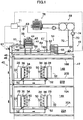
- Fig. 1 is a conceptual view showing a cooling system 10 for an electronic device of a first embodiment of the present invention.
- server rooms 14A and 14B are formed in a first floor and a second floor respectively.
- Underfloor chambers 22A and 22B are respectively formed on the back sides of floor surfaces 20A and 20B on the first floor and the second floor.
- a plurality of air outlet ports are disposed in the floor surfaces 20A and 20B.
- Cold air from air-conditioning machines 78 (see Fig. 3 ) which will be described later is blown into the server rooms 14A and 14B from the floor surfaces 20A and 20B through the underfloor chambers 22A and 22B.
- the air outlet ports are preferably disposed in the vicinity of the front surface side of each of servers 28, and the cold air blown from them is supplied to the servers 28, whereby the servers 28 can be efficiently cooled.
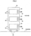
- server racks 26 are placed in the server rooms 14A and 14B, and a plurality of severs 28 are stored in the server racks 26 in the state stacked in layer.
- the server rack 26 is preferably disposed to be movable by being provided with moving casters 24.
- the server 28 is equipped with a fan 30, and by taking in the air of the server rooms 14A and 14B and discharging the air as shown by the arrow 32, the heat which generates in the server 28 is discharged from the server28.
- the numbers of the server rooms 14A and 14B, the number of the server racks 26 placed in the server rooms 14A and 14B, the number of the servers 28 stacked in layer on the server rack 26 and the like are only examples, and they are not limited to the numbers in Figs. 1 and 2 .
- an evaporator 34 is provided at each of the servers 28 stored in the server rack 26.
- it is shown with the server 28 instead of the server rack 26.
- a cooling coil 36 is provided inside the evaporator 34.
- a refrigerant liquid flowing in the cooling coil 36 evaporates due to high-temperature air generating from the server 28, and thereby, takes vaporization heat from the periphery to be gasified. Thereby, the server 28 itself and high-temperature air discharged from the server 28 are cooled.
- a cooling tower 38 is provided on the roof of the building 12, and a circulation line 40 in which the refrigerant naturally circulates is formed between the cooling tower 38 and the aforementioned respective evaporators 34. More specifically, spiral piping 41 in which the refrigerant flows is stored in the cooling tower 38, and a sprinkling pipe 42 which sprinkles water to the spiral piping 41 is provided above the spiral piping 41. Further, a fan 44 is provided above the sprinkling pipe 42, and outside air is taken in from a side surface opening of the cooling tower 38 and discharged from a top surface opening, whereby a counter current of the sprinkled water and the outside air taken therein is formed, and thereby, the outside air is cooled so that the temperature becomes lower than the intake air temperature.
- the cooling coil 36 provided in the evaporator 34 and the spiral piping 41 provided in the cooling tower 38 are connected by return piping 46 (refrigerant gas piping) for returning the refrigerant gas which is gasified in the evaporator 34 to the cooling tower 38, and supply piping 48 (refrigerant liquid piping) for supplying the refrigerant liquid which is liquefied by cooling and condensing the refrigerant gas in the cooling tower 38 to the evaporator 34.
- return piping 46 refrigerant gas piping
- supply piping 48 refrigerant liquid piping
- the return piping 46 and the supply piping 48 branch out halfway, and pass through the underfloor chambers 22A and 22B on the first floor and the second floor to be connected to the evaporators 34 of the servers 28 placed in the server room 14A on the first floor and the evaporators 34 of the servers 28 placed in the server room 14B on the second floor.
- expression of the refrigerant includes both refrigerant gas in a gaseous state, and a refrigerant liquid in a liquid state, and in Fig. 1 , the flow direction of the refrigerant gas is shown by the white arrow, and the flow direction of the refrigerant liquid is shown by the black arrow.
- the circulation line 40 for naturally circulating the refrigerant is formed between the evaporator 34 and the cooling tower 38. More specifically, a heat pipe with no power in which the refrigerant is sealed is constructed by the evaporator 34, the cooling tower 38 and the circulation line 40. Further, since the heat generation amount from the server 28 becomes large and refrigerant gas at a high temperature can be formed, the cooling temperature for condensing the refrigerant gas can be set to be high, and the refrigerant gas can be condensed with the cooling capacity by the cooling tower 38. The condensed refrigerant liquid flows down to the evaporator 34 located below the cooling tower 38.
- each of the evaporators 34 is provided with a temperature sensor 50 which measures the temperature of the air after the high-temperature air discharged from the server 28 is cooled with the evaporator 34, and a valve 52 (flow regulating device) for regulating the supply flow rate (refrigerant flow rate) of the refrigerant which is supplied to the cooling coil 36 is provided at an outlet port of the cooling coil 36.
- a controller not illustrated automatically regulates the opening degree of the valve 52 based on the measured temperature by the temperature sensor 50.
- the air in the server rooms 14A and 14B is taken into the servers by the fans 30, and the air is heated. Heat exchange is performed between the heated high-temperature air and the evaporators 34, and the temperature of the cooled air is measured by the temperature sensors 50.
- the condensing temperature which is lower than the vaporization (evaporation) temperature is required, unlike the conventional compression type air-conditioning system. Therefore, if the vaporization temperature can be set to be high, the condensing temperature, namely, the temperature of the outside air used in the cooling tower 38 can be made high, and the cooling capacity in the cooling tower 38 can be used under the outside air condition at a higher temperature. More specifically, in the intermediate seasons (spring season and autumn season) in which the outside air temperature is relatively high, cooling with only the cooling tower is also made possible, and running cost can be reduced by suppressing the operation of a refrigerator 68.
- a heat exchanger 54 having cooling capacity larger than the cooling tower 38 is installed in addition to the cooling tower 38, and the heat exchanger 54 is provided in a parallel line 64 branched from the circulation line 40. More specifically, as shown in Fig. 1 , parallel return piping 58 and parallel supply piping 60 which are branched from the return piping 46 and the supply piping 48 respectively are connected to a secondary side coil 62 of the heat exchanger 54. Thereby, the heat exchanger 54 is disposed to have parallel relation in the flow of the refrigerant with respect to the cooling tower 38.
- a primary side coil 66 of the heat exchanger 54 is connected to cooling water supply piping 70 and cooling water return piping 72 from the refrigerator 68, and the cooling water supply piping 70 is provided with a delivery pump 74.
- the cooling water (primary refrigerant) produced in the refrigerator 68 exchanges heat with the refrigerant (secondary refrigerant) in the heat exchanger 54, and cools the refrigerant.
- the working electric power for the refrigerator 68 can be reduced by connecting the refrigerator 68 to a cooling tower 76 different from the above described cooling tower 38 and using it as a cold heat source of the refrigerator 68.
- the structure of the cooling tower 76 is the same as that of the above described cooling tower 38.
- the parallel return piping 58 is provided with a parallel valve 59, a shut-off valve 61 is provided in the vicinity of the cooling tower 38 in the supply line 48, and the cooling water supply piping 70 in which cooling water flows is also provided with a valve 69.
- an outside air temperature sensor 63 which measures the outside air temperature is provided in the vicinity of the cooling tower 38, and temperature sensors 65 and 67 are provided at a cooling tower outlet port (refrigerant liquid side) and a heat exchanger outlet port (refrigerant liquid side).
- the measurement results of the respective temperature sensors 63, 65 and 67 are sequentially input in a parallel control part 71, and the parallel control part 71 controls the respective valves 59, 61 and 69 based on the measurement result.
- the temperature sensors 65 and 67 are provided at the cooling tower outlet port and the heat exchanger outlet port, but pressure sensors (not illustrated) which measure the pressure of the refrigerant flowing in the piping can be provided, and both the liquid temperature sensors 65 and 67 and the pressure sensors may be provided.
- the parallel control part 71 calculates the capacity to cool the refrigerant in the cooling tower 38 from the measurement result of the outside temperature sensor 63, and regulates the opening degree amount of the parallel valve 59 from the calculation result, whereby the parallel control part 71 controls the refrigerant amount to be fed to the heat exchanger 54.
- the cooling tower 38 and the heat exchanger 54 can be efficiently used so that the running cost becomes the minimum in accordance with the cooling load necessary for condensing the refrigerant gas vaporized in the evaporator 34.
- the cooling capacity of the cooling tower 38 significantly depends on the outside air temperature, and therefore, by conducting the control as described above, a part of the refrigerant flowing in the circulation line 40 can be caused to flow into the heat exchanger 54 automatically in accordance with the variation in the outside air temperature. Therefore, only insufficiency of the cooling capacity of the cooling tower 38 needs to be supplied by the heat exchanger 54. Thereby, the running cost can be further reduced.
- the parallel control part 71 regulates the opening degree amount of the parallel valve 59 so that the measurement result of the temperature sensor 65 at the outlet port of the cooling tower becomes a predetermined value and controls the refrigerant amount to be fed to the heat exchanger 54.
- the cooling capacity which the cooling tower 38 has at the point of time of measurement can be grasped.
- a part of the refrigerant flowing in the circulation line 40 can be automatically caused to flow in the heat exchanger 54 by automatically regulating the opening degree amount of the parallel valve 59 based on the measurement result, and therefore, only insufficiency of the cooling capacity of the cooling tower 38 needs to be supplied by the heat exchanger 54. Thereby, the running cost can be further reduced.
- the temperature sensor 67 provided at the outlet port of the heat exchanger is measured, and thereby, the temperature of the refrigerant to be supplied to the evaporators 34 can be known. Accordingly, by controlling the opening degree amount of the valve 69 of the cooling water supply piping 70 based on the measurement result, the refrigerant can be prevented from being cooled more than necessary in the heat exchanger 54. Further, in the summer season when the cooling capacity of the cooling tower 38 reduces the most, combined use of the cooling tower 38 and the heat exchanger 54 sometimes becomes a disadvantage from the viewpoint of the running cost. Thus, in such a case, by closing the shut-off valve 61 when the measurement temperature of the outside temperature sensor 63 reaches a predetermined value or higher, the running cost can be further reduced.
- the two cooling devices that are the cooling tower 38 and the heat exchangers 54 are included, and each of them bears each share of work like this. Thereby, stable operation of the cooling system can be guaranteed, and the running cost for cooling the refrigerant can be reduced.
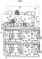
- Fig. 3 is a conceptual view showing a cooling system 100 for an electronic device of a second embodiment, showing features being not according to the present invention.
- the same members and constitutions as those in the first embodiment will be omitted.
- an air-conditioning machine 78 for cooling server rooms 14A and 14B is provided in the constitution of the cooling system 10 of the first embodiment, and the refrigerant of the circulation line 40 is used as a cold heat source of the air-conditioning machine 78.
- machine rooms 80A and 80B are respectively provided adjacently to the server rooms 14A and 14B, and the air-conditioning machines 78 are installed in the machine rooms 80A and 80B, respectively.
- inlet ducts 79 which take the air of the server rooms 14A and 14B into the air-conditioning machine 78 via the machine rooms 80A and 80B are placed by being penetrated through partition walls 82 which partition the server rooms 14A and 14B and the machine rooms 80A and 80B, and one end of the inlet duct 79 is connected to a cooling part 84 of the air-conditioning machine 78.
- an outlet duct 81 is connected to an air blower 86 of the air-conditioning machine, and the other end is extensively provided in each of underfloor chambers 22A and 22B through the partition wall 82.
- the air taken into each of the air-conditioning machines 78 via each of the intake ducts 79 is cooled by each of the cooling parts 84 of each of the air-conditioning machines 78, and blown into each of the underfloor chambers 22A and 22B via each of the outlet ducts 81 by each of the air blowers 86.
- the air is blown out to each of the server rooms 14A and 14B from floor surfaces 20A and 20B.
- the air outlets (not illustrated) of the floor surfaces 20A and 20B are preferably formed so that cooling air is blown to the vicinity of the front surface of the server 28.
- the front surface of the server 28 means the opposite side of the evaporator 34.
- cooling part 84 of the air-conditioning machine 78 is connected to an air-conditioning circulation line 88 branched from the circulation line 40. More specifically, air-conditioning supply piping 88A and air-conditioning return piping 88B which constitute the air-conditioning circulation line 88 are connected to the cooling part 84 of the air-conditioning machine 78.
- the refrigerant of the circulation line 40 of which running cost for cooling the refrigerant is low is used as the cold heat source of the air-conditioning machine 78 for cooling the server rooms 14A and 14B with cold air. Thereby, the running cost for operating the air-conditioning machine 78 also can be reduced.
- the air-conditioning machine 78 and the evaporator 34 for cooling the server 28 in combination, generation of heat accumulation (local high-temperature regions) in the server rooms 14A and 14B can be suppressed, and the supply air temperature from the air-conditioning machine 78 which air-conditions the entire server room can be raised, as compared with the conventional air-conditioning system (the method for air-conditioning by circulating air in the entire electronic equipment room by air-conditioning with the air blown from the floor shown in Japanese Patent Application Laid-Open No. 2004-232927 ).
- vaporization (evaporation) temperature of the refrigerant can be made high as compared with the conventional system, and the capacity of the cooling tower 38 can be sufficiently used.
- supplying the refrigerant of the circulation line 40 to the cooling part 84 of the air-conditioning machine 78 contributes to both energy saving of the air-conditioning machine 78 and exhibition of the capacity of the cooling tower 38.
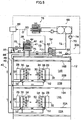
- Fig. 4 is a conceptual view showing a cooling system 200 for an electric device of a third embodiment, showing features being not according to the present invention. Explanation of the same members and constitutions as those in the second embodiment will be omitted.
- the cooling system 200 of the third embodiment has the constitution in which a plurality of servers 28 equipped with the evaporators 34 are divided into groups, and thereby, the cooling system 200 can be operated with the groups being edge-cut from each other, in addition to the constitution of the cooling system 100 of the second embodiment.
- a plurality of the servers 28 equipped with the evaporators 34 are divided into a plurality of groups.
- the servers 28 installed in the server room 14A on the first floor are grouped as one group, and the servers 28 installed in the server room 14B on the second floor are grouped as another group.
- the method for grouping is not limited to the above description, and the servers 28 can be further divided into small groups.
- Two of heat exchangers 90 for groups which is the number of groups into which the servers 28 are divided, are provided halfway in the circulation line 40, and the circulation line 40 is constituted of a main circulation line 40A in which the refrigerant circulates between the cooling tower 38 and/or the heat exchanger 54, and the heat exchanger 90 for a group, and a group circulation line 40B in which the refrigerant circulates between the heat exchanger 90 for a group and the evaporator 34.
- the air-conditioning machines 78 are divided into two groups of the air-conditioning machine 78 installed in the machine room 80A on the first floor, and the air-conditioning machine 78 installed in the machine room 80B on the second floor.
- the group circulation lines 40B corresponding to the groups are connected to the cooling parts 84 of the respective air-conditioning machines 78.
- the following effect can be exhibited in addition to the effect of.the second embodiment described above.
- the abnormality does not affect the other group. Accordingly, occurrence of abnormality to cooling of all the servers 28 placed in the server rooms 14A and 14B can be prevented. Further, by also grouping the air-conditioning machines 78, even if abnormality such as stoppage of the flow of the refrigerant occurs in one group, the abnormality does not affect the cooling parts 84 of the air-conditioning machines 78 of the other group.
- Fig. 5 is a conceptual view of a cooling system 300 for an electronic device of a fourth embodiment, showing features being not according to the present invention, and is a view made by changing Fig. 1 so that the cooling tower 38 and the heat exchanger 54 are in series positional relation.
- the redundant parts are omitted, and the same members and constitutions are described by being assigned with the same reference numerals and characters.
- the refrigerant gas which is vaporized in the evaporator 34 reaches the cooling tower 38 via the return piping 46 of the circulation line 40, where the refrigerant is cooled and becomes a refrigerant liquid, and thereafter, the refrigerant flows into the heat exchanger 54 via return piping 75 of a series line 73.
- the refrigerant liquid further cooled by heat exchange with the primary refrigerant (cooling water) flows into the supply piping 48 of the circulation line 40 via outward piping 77 of the series line 73.
- the heat exchanger 54 is disposed in the series relation with respect to the cooling tower 38 in the flow of the refrigerant.
- a valve 69 and a regulating valve 87 are provided in the cooling water supply piping 70 and the cooling tower outlet port, the outside air temperature sensor 63 is provided near the cooling tower 38, and the temperature sensors 65 and 67 are provided at the cooling tower outlet port and the heat exchanger outlet port, respectively.
- a bypass line 83 which can pass the refrigerant gas returning from the evaporator 34 into the heat exchanger 54 is provided, and a bypass valve 85 is provided in the bypass line 83.
- the bypass line 83 is written to be in a wavy shape in Fig. 5 .
- the measurement results of the respective temperature sensors 63, 65 and 67 are input in a series control part 89, and the series control part 89 controls the respective valves 69, 85 and 87 based on the measurement results.
- the series control mechanism is formed.
- the temperature sensors 65 and 67 are disposed at the cooling tower outlet port and the heat exchanger outlet port respectively, but the pressure sensor which measures the pressure of the refrigerant flowing in the piping can be provided, and both the temperature sensors and the pressure sensors may be provided.
- the series control part 89 conducts control so that the measurement result at the heat exchanger outlet sensor becomes a predetermined value, and thereby, the series control part 89 can control the heat amount of the primary refrigerant so that only insufficiency of the cooling capacity of the cooling tower 38 is supplied in the heat exchanger 54 when the refrigerant sequentially flows into the heat exchanger 54 from the cooling tower 38. Accordingly, unnecessary cooling energy is not required in the heat exchanger 54.
- the cooling capacity of the cooling tower 38 varies depending on the outside air temperature, and therefore, when the refrigerant amount flowing in the spiral piping 41 in the cooling tower 38 is too large in the summer season and intermediate season, the refrigerant sometimes cannot be cooled to the temperature required for naturally circulating the refrigerant. Accordingly, the refrigerant gas flow rate to the cooling tower 38 is controlled by operating the opening degrees of the bypass valve 85 provided in the bypass line and the regulating valve 87 provided in the outlet port of the cooling tower so that the measurement result of the temperature sensor 65 at the outlet port of the cooling tower is controlled to be a predetermined value. Thereby, the temperature of the outside air which is the cold heat source of the cooling tower 38 can be effectively used irrespective of a summer season, intermediate seasons or a winter season, and therefore, the running cost can be further reduced.
- the predetermined value refers to the temperature or pressure required for naturally circulating the refrigerant in the circulation line.
- the series control part 89 fully closes the regulating valve 87 and fully opens the bypass valve 85 so as to shut off the return of the refrigerant gas to the cooling tower 38 from the evaporator 34 and guide all the refrigerant gas to the heat exchanger 54, when the measurement result of the outside air temperature sensor 63 reaches a predetermined value or more in a summer season. Thereby, the running cost in the summer season can be further reduced.
- an electronic device required to perform a precise operation with an amount of heat generation from itself being large such as a computer and a server, can be efficiently cooled at low running cost.
- the air temperature conditions under which the server mounted on the server rack normally operates are specified, and intake air condition is generally 25°C or lower though it depends on the server.
- the conventional air conditioning of a method of blowing air from the floor is operated with the temperature of the supply air from the package air-conditioning machine at about 18°C, and the temperature of the return air to the air-conditioning machine at about 26°C.
- server rack exhaust air normally at about 40°C
- supply air are partially mixed and are taken into the server rack, and therefore, in order to satisfy the server rack intake air temperature of 25°C, the supply air temperature has to be low (actual air temperature is about 18°C).
- the outlet port air temperature of 25°C is satisfied. Therefore, even if the supply air temperature is not low, namely, is higher than 18°C, the server intake air temperature of 25°C can be satisfied, and when, for example, the supply air temperature of 23°C and the conventional temperature of 18°C are compared, the temperature can be increased by 5°C.
- the above described efficiency (COP) can be increased by about 3% by increasing the supply air temperature by 1°C, and by increase of the supply air temperature by 5°C, the COP can be increased by about 15%.
- the influence of the heat accumulation on an electronic device such as the server 28 is conventionally prevented by reducing the temperature of the air-conditioning air which is supplied to the server rooms 14A and 14B from the air-conditioning machine 78.
- the supply air temperature is reduced like this, the temperature of the refrigerant gas which is vaporized in the evaporator 34 becomes too low.
- the set temperature of the refrigerant device which cools and condenses the refrigerant gas has to be made low, and the cooling device having a cooling capacity which is not so large, such as the cooling tower 38 cannot be used.
- the supply air temperature can be prevented from becoming too low, and therefore, the cooling device having a cooling capacity which is not so large, such as the cooling tower 38 can be used. Further, as a result that the supply air temperature can be increased, the COP of the entire cooling system can be increased. In this case, even with the constitution in which the refrigerant which is cooled in the cooling tower 38 is supplied to the cooling part 84 of the air-conditioning machine 78, heat accumulation can be sufficiently prevented, and no problem arises.
- the cooling tower 38 is disposed above the evaporator 34 to circulate the refrigerant naturally, but the refrigerant can be transferred with refrigerant pumps instead of being naturally circulated by providing the refrigerant pumps not illustrated in the supply piping 48 of the circulation line 40 and the branched supply piping 60, for example.
- the cooling tower 38 does not have to be disposed above the evaporator 34, and the evaporator 34 and the cooling tower 38 can be freely disposed without limitation on the disposition of the evaporator 34 and the cooling tower 38.
- the cooling systems 10, 100 and 200 in the above described first to third embodiments are described with the example of the server 26 as an electronic device, but the present invention can be applied to all electronic devices which are required to perform precise operations with the heat generation amount from itself being large.
Claims (3)
- Système de refroidissement (10, 100, 200, 300) pour un dispositif électronique comprenant :un local des dispositifs (14A, 14B), dans lequel est placée une pluralité de dispositifs électroniques (28),un évaporateur (34), qui est prévu à proximité de chacun des dispositifs électroniques (28) et refroidit l'air sortant du dispositif électronique par vaporisation d'un réfrigérant en même temps que le dispositif électronique produit de la chaleur,un condensateur (38), qui est prévu à un emplacement plus haut que l'évaporateur (34) et refroidit le réfrigérant au moyen d'air extérieur et condense le réfrigérant vaporisé,une tuyauterie de circulation (40), dans laquelle le réfrigérant circule naturellement entre l'évaporateur (34) et le condensateur (38),un échangeur thermique (54), qui est prévu à un emplacement plus haut que l'évaporateur (34) et refroidit et condense le réfrigérant,un réfrigérateur (68) pour refroidir le réfrigérant qui s'écoule dans l'échangeur de chaleur (54), etune tuyauterie parallèle (58, 60, 64), qui constitue un trajet d'écoulement pour le réfrigérant, raccordée à la tuyauterie de circulation (40) et prévue de façon que l'échangeur de chaleur est relié parallèlement au condensateur (38),
caractérisé en ce queun mécanisme de contrôle parallèle, qui contrôle un volume de réfrigérant amené à la tuyauterie parallèle (58, 60, 64) depuis la tuyauterie de circulation (40), système, dans lequelle mécanisme de contrôle parallèle comprendun capteur de température d'air extérieur (63), qui mesure la température extérieure,une soupape parallèle (59), qui est prévue dans la tuyauterie parallèle (58, 60, 64) une fois dérivée de la ligne de circulation (40), et qui régule un volume de réfrigérant qui est un gaz réfrigérant revenant de l'évaporateur (34) et passant dans l'échangeur de chaleur (54), etune partie de contrôle parallèle (71), qui calcule une capacité de refroidissement du réfrigérant dans le condensateur (38) à partir d'un résultat de mesure du capteur de température d'air extérieur (63) et régule un degré d'ouverture de la soupape parallèle (59) à partir d'un résultat du calcul pour contrôler un volume de réfrigérant amené à l'échangeur de chaleur (54) depuis la tuyauterie de circulation (40). - Système de refroidissement (10, 100, 200, 300) pour un dispositif électronique comprenant :un local des dispositifs (14A, 14B), dans lequel est placée une pluralité de dispositifs électroniques (28),un évaporateur (34), qui est prévu à proximité de chacun des dispositifs électroniques (28) et refroidit l'air sortant du dispositif électronique par vaporisation d'un réfrigérant en même temps que le dispositif électronique produit de la chaleur,un condensateur (38), qui est prévu à un emplacement plus haut que l'évaporateur (34) et refroidit le réfrigérant au moyen d'air extérieur et condense le réfrigérant vaporisé,une tuyauterie de circulation (40), dans laquelle le réfrigérant circule naturellement entre l'évaporateur (34) et le condensateur (38),un échangeur de chaleur (40), qui est prévu à un emplacement plus haut que l'évaporateur (34) et refroidit et condense le réfrigérant,un réfrigérateur (68) pour refroidir le réfrigérant qui s'écoule dans l'échangeur de chaleur (54) etune tuyauterie parallèle (58, 60, 64), qui constitue un trajet d'écoulement pour le réfrigérant, raccordée à la tuyauterie de circulation (40) et prévue de façon que l'échangeur de chaleur est relié parallèlement au condensateur (38),caractérisé en ce que
un mécanisme de contrôle parallèle, qui contrôle un volume de réfrigérant amené à la tuyauterie parallèle (58, 60, 64) depuis la tuyauterie de circulation (40), système, dans lequel
le mécanisme de contrôle parallèle comprend
un capteur d'orifice de sortie de condensateur (65) qui mesure la température et/ou la pression du réfrigérant à un orifice de sortie du condenseur (38),
une soupape parallèle (59), qui est prévue dans la tuyauterie parallèle une fois dérivée de la tuyauterie de circulation (40), et qui régule un volume de réfrigérant qui est un gaz réfrigérant revenant de l'évaporateur et passant dans l'échangeur de chaleur, et
une partie de contrôle parallèle (71), qui régule un degré d'ouverture de la soupape parallèle de façon qu'un résultat de mesure du capteur d'orifice de sortie de condensateur (65) devient une valeur prédéterminée pour contrôler un volume de réfrigérant amené à l'échangeur de chaleur (54) depuis la tuyauterie de circulation (40). - Système de refroidissement (10, 100, 200, 300) pour un dispositif électronique suivant la revendication 1 ou 2,
dans lequel le dispositif électronique est un serveur (28) et le local des dispositifs est la salle des serveurs (14A, 14B).
Priority Applications (3)
| Application Number | Priority Date | Filing Date | Title |
|---|---|---|---|
| EP12002922.8A EP2503866B1 (fr) | 2008-02-13 | 2009-02-09 | Système de refroidissement pour équipement électronique |
| EP12002923.6A EP2498024B1 (fr) | 2008-02-13 | 2009-02-09 | Système de refroidissement pour équipement électronique |
| EP12002924.4A EP2498025A3 (fr) | 2008-02-13 | 2009-02-09 | Système de refroidissement pour équipement électronique |
Applications Claiming Priority (1)
| Application Number | Priority Date | Filing Date | Title |
|---|---|---|---|
| JP2008032096A JP4780479B2 (ja) | 2008-02-13 | 2008-02-13 | 電子機器の冷却システム |
Related Child Applications (6)
| Application Number | Title | Priority Date | Filing Date |
|---|---|---|---|
| EP12002924.4A Division-Into EP2498025A3 (fr) | 2008-02-13 | 2009-02-09 | Système de refroidissement pour équipement électronique |
| EP12002924.4A Division EP2498025A3 (fr) | 2008-02-13 | 2009-02-09 | Système de refroidissement pour équipement électronique |
| EP12002922.8A Division-Into EP2503866B1 (fr) | 2008-02-13 | 2009-02-09 | Système de refroidissement pour équipement électronique |
| EP12002922.8A Division EP2503866B1 (fr) | 2008-02-13 | 2009-02-09 | Système de refroidissement pour équipement électronique |
| EP12002923.6A Division EP2498024B1 (fr) | 2008-02-13 | 2009-02-09 | Système de refroidissement pour équipement électronique |
| EP12002923.6A Division-Into EP2498024B1 (fr) | 2008-02-13 | 2009-02-09 | Système de refroidissement pour équipement électronique |
Publications (3)
| Publication Number | Publication Date |
|---|---|
| EP2091314A2 EP2091314A2 (fr) | 2009-08-19 |
| EP2091314A3 EP2091314A3 (fr) | 2011-11-02 |
| EP2091314B1 true EP2091314B1 (fr) | 2016-04-20 |
Family
ID=40717125
Family Applications (4)
| Application Number | Title | Priority Date | Filing Date |
|---|---|---|---|
| EP12002922.8A Not-in-force EP2503866B1 (fr) | 2008-02-13 | 2009-02-09 | Système de refroidissement pour équipement électronique |
| EP09001786.4A Not-in-force EP2091314B1 (fr) | 2008-02-13 | 2009-02-09 | Système de refroidissement pour équipement électronique |
| EP12002924.4A Withdrawn EP2498025A3 (fr) | 2008-02-13 | 2009-02-09 | Système de refroidissement pour équipement électronique |
| EP12002923.6A Not-in-force EP2498024B1 (fr) | 2008-02-13 | 2009-02-09 | Système de refroidissement pour équipement électronique |
Family Applications Before (1)
| Application Number | Title | Priority Date | Filing Date |
|---|---|---|---|
| EP12002922.8A Not-in-force EP2503866B1 (fr) | 2008-02-13 | 2009-02-09 | Système de refroidissement pour équipement électronique |
Family Applications After (2)
| Application Number | Title | Priority Date | Filing Date |
|---|---|---|---|
| EP12002924.4A Withdrawn EP2498025A3 (fr) | 2008-02-13 | 2009-02-09 | Système de refroidissement pour équipement électronique |
| EP12002923.6A Not-in-force EP2498024B1 (fr) | 2008-02-13 | 2009-02-09 | Système de refroidissement pour équipement électronique |
Country Status (4)
| Country | Link |
|---|---|
| US (3) | US7855890B2 (fr) |
| EP (4) | EP2503866B1 (fr) |
| JP (1) | JP4780479B2 (fr) |
| PL (1) | PL2091314T3 (fr) |
Families Citing this family (106)
| Publication number | Priority date | Publication date | Assignee | Title |
|---|---|---|---|---|
| BRPI0704566A2 (pt) * | 2007-09-18 | 2009-05-12 | Whirlpool Sa | estação de docagem para um computador |
| US8170724B2 (en) * | 2008-02-11 | 2012-05-01 | Cray Inc. | Systems and associated methods for controllably cooling computer components |
| JP5017296B2 (ja) * | 2009-03-03 | 2012-09-05 | 株式会社東芝 | 電子機器 |
| US7903404B2 (en) * | 2009-04-29 | 2011-03-08 | Hewlett-Packard Development Company, L.P. | Data centers |
| JP2011171499A (ja) * | 2010-02-18 | 2011-09-01 | Hitachi Plant Technologies Ltd | 電子機器の冷却方法及び冷却システム |
| SG171566A1 (en) * | 2009-12-01 | 2011-06-29 | Hitachi Plant Technologies Ltd | Cooling method and cooling system of electronic device |
| WO2011097232A1 (fr) | 2010-02-02 | 2011-08-11 | Exaflop Llc | Refroidissement à eau mélangée pour centre de données |
| JP5460362B2 (ja) * | 2010-02-04 | 2014-04-02 | 株式会社日立製作所 | 電子機器の冷却システム |
| JP5491923B2 (ja) * | 2010-03-26 | 2014-05-14 | 株式会社日立製作所 | 電子機器の冷却システム |
| US8974274B2 (en) | 2010-04-16 | 2015-03-10 | Google Inc. | Evaporative induction cooling |
| JP2011237887A (ja) * | 2010-05-06 | 2011-11-24 | Hitachi Plant Technologies Ltd | 電子機器の冷却方法及び冷却システム |
| JP5610839B2 (ja) * | 2010-05-11 | 2014-10-22 | 株式会社日立製作所 | 冷却システム |
| JP5351097B2 (ja) * | 2010-06-18 | 2013-11-27 | 株式会社日立製作所 | 冷媒循環装置 |
| CA3013470C (fr) * | 2010-06-23 | 2021-04-13 | Inertech Ip Llc | Centre de donnees modulaire a haute densite et a economie d'espace et systeme de refroidissement efficace en energie |
| JP2012007865A (ja) * | 2010-06-28 | 2012-01-12 | Hitachi Plant Technologies Ltd | 冷却システム |
| WO2012003895A1 (fr) * | 2010-07-06 | 2012-01-12 | Sam Technologies Gmbh | Système et procédé de refroidissement d'un ordinateur |
| EP2413048B1 (fr) * | 2010-07-30 | 2013-06-05 | Grundfos Management A/S | Unité de chauffage d'eau potable |
| JP5676966B2 (ja) * | 2010-08-10 | 2015-02-25 | 株式会社日立製作所 | 冷却システム |
| JP5661493B2 (ja) * | 2010-08-23 | 2015-01-28 | 高砂熱学工業株式会社 | 複数階を有する施設の空調システム及び空調システムの運転方法 |
| WO2012029404A1 (fr) * | 2010-08-31 | 2012-03-08 | 日本電気株式会社 | Système de refroidissement de dispositif électronique |
| CN101968245A (zh) * | 2010-11-02 | 2011-02-09 | 浙江大学 | 一种水冷式节能型机房空调系统 |
| JP5541107B2 (ja) * | 2010-11-17 | 2014-07-09 | 富士通株式会社 | 空調システム |
| CN102478936A (zh) * | 2010-11-30 | 2012-05-30 | 英业达股份有限公司 | 一种服务器架构 |
| EP2657628B1 (fr) * | 2010-12-22 | 2023-07-05 | Mitsubishi Electric Corporation | Dispositif composite de fourniture d'eau chaude et de climatisation |
| WO2012124723A1 (fr) * | 2011-03-14 | 2012-09-20 | 富士電機株式会社 | Système de conditionnement d'air à utilisation d'air extérieur et appareil de conditionnement d'air associé |
| JP5773708B2 (ja) * | 2011-03-31 | 2015-09-02 | 三菱重工業株式会社 | 熱交換器及び熱交換器の余寿命推定方法 |
| US9307674B2 (en) | 2011-05-06 | 2016-04-05 | International Business Machines Corporation | Cooled electronic system with liquid-cooled cold plate and thermal spreader coupled to electronic component |
| US9027360B2 (en) | 2011-05-06 | 2015-05-12 | International Business Machines Corporation | Thermoelectric-enhanced, liquid-based cooling of a multi-component electronic system |
| JP5750304B2 (ja) * | 2011-05-18 | 2015-07-22 | 株式会社日立製作所 | 電子機器の冷却システム |
| US9179574B2 (en) * | 2011-05-24 | 2015-11-03 | International Business Machines Corporation | Cooling unit for container-type data center |
| US8857204B2 (en) * | 2011-09-23 | 2014-10-14 | R4 Ventures Llc | Real time individual electronic enclosure cooling system |
| US8711563B2 (en) * | 2011-10-25 | 2014-04-29 | International Business Machines Corporation | Dry-cooling unit with gravity-assisted coolant flow |
| US8687364B2 (en) * | 2011-10-28 | 2014-04-01 | International Business Machines Corporation | Directly connected heat exchanger tube section and coolant-cooled structure |
| TWI445493B (zh) * | 2011-11-11 | 2014-07-11 | Inventec Corp | 散熱系統 |
| CN202392893U (zh) * | 2011-11-15 | 2012-08-22 | 开利公司 | 空调末端装置、空调设备及数据中心 |
| US9043035B2 (en) | 2011-11-29 | 2015-05-26 | International Business Machines Corporation | Dynamically limiting energy consumed by cooling apparatus |
| US9167721B2 (en) * | 2011-11-29 | 2015-10-20 | International Business Machines Corporation | Direct facility coolant cooling of a rack-mounted heat exchanger |
| CA2863198C (fr) * | 2012-02-14 | 2018-08-14 | Nec Corporation | Dispositif de refroidissement et systeme de refroidissement |
| US10209003B2 (en) * | 2012-02-21 | 2019-02-19 | Thermal Corp. | Electronics cabinet and rack cooling system and method |
| JP5930803B2 (ja) * | 2012-03-30 | 2016-06-08 | 日立アプライアンス株式会社 | 空調制御システム、および、空調制御方法 |
| US9313929B1 (en) | 2012-05-29 | 2016-04-12 | Google Inc. | Managing data center airflow |
| US9278303B1 (en) | 2012-05-29 | 2016-03-08 | Google Inc. | Managing data center airflow |
| JP5902053B2 (ja) | 2012-06-28 | 2016-04-13 | 株式会社日立製作所 | 冷却システム及び冷却方法 |
| WO2014011706A1 (fr) | 2012-07-09 | 2014-01-16 | Inertech Ip Llc | Systèmes et procédés d'alimentation sans coupure (ups) à moyenne tension multiniveaux sans transformateur |
| CA2926777C (fr) | 2012-10-09 | 2021-11-02 | Inertech Ip Llc | Systemes et procedes de refroidissement comprenant un cycle d'evaporateur de garniture de fluide frigorigene liquide pompe en series |
| CN103052304A (zh) * | 2012-12-14 | 2013-04-17 | 广州高澜节能技术股份有限公司 | 一种服务器机柜冷却系统 |
| DE102013111053A1 (de) * | 2013-01-18 | 2014-07-24 | Rittal Gmbh & Co. Kg | Verfahren zum Klimatisieren einer IT-Umgebung bzw. einer Umgebung, die Wärmeerzeuger enthält |
| CN103968478B (zh) * | 2013-02-01 | 2018-02-23 | Lg电子株式会社 | 冷却系统及其控制方法 |
| JP6275959B2 (ja) * | 2013-05-22 | 2018-02-07 | 株式会社Nttファシリティーズ | 装置冷却システム |
| TW201448720A (zh) * | 2013-06-14 | 2014-12-16 | Hon Hai Prec Ind Co Ltd | 貨櫃式伺服器組合 |
| WO2015004920A1 (fr) * | 2013-07-12 | 2015-01-15 | 日本電気株式会社 | Système de refroidissement, et procédé de commande de quantité d'alimentation en frigorigène dans celui-ci |
| US9774190B2 (en) | 2013-09-09 | 2017-09-26 | Inertech Ip Llc | Multi-level medium voltage data center static synchronous compensator (DCSTATCOM) for active and reactive power control of data centers connected with grid energy storage and smart green distributed energy sources |
| US10254021B2 (en) | 2013-10-21 | 2019-04-09 | Inertech Ip Llc | Cooling systems and methods using two cooling circuits |
| US11306959B2 (en) | 2013-11-06 | 2022-04-19 | Inertech Ip Llc | Cooling systems and methods using two circuits with water flow in series and counter flow arrangement |
| CN104684344A (zh) * | 2013-11-29 | 2015-06-03 | 国际商业机器公司 | Pcm冷却设备,冷却系统和控制该系统的方法和单元 |
| US10111361B2 (en) * | 2014-01-08 | 2018-10-23 | Nautilus Data Technologies, Inc. | Closed-loop cooling system and method |
| CN103939994A (zh) * | 2014-04-09 | 2014-07-23 | 北京德能恒信科技有限公司 | 一种机房节能空调 |
| WO2016031195A1 (fr) | 2014-08-27 | 2016-03-03 | 日本電気株式会社 | Refroidisseur à changement de phase et procédé de refroidissement à changement de phase |
| CN105403067B (zh) * | 2014-09-11 | 2017-08-11 | 华北水利水电大学 | 一种利用工业余热制冷凝水除雾冷却塔 |
| WO2016057854A1 (fr) | 2014-10-08 | 2016-04-14 | Inertech Ip Llc | Systèmes et procédés permettant de refroidir un équipement électrique |
| WO2016065087A1 (fr) | 2014-10-21 | 2016-04-28 | Inertech Ip Llc | Systèmes et procédés de commande d'onduleurs à calage par diode à multiples niveaux utilisant une modulation de largeur d'impulsion à vecteur spatial (svpwm) |
| US10375901B2 (en) | 2014-12-09 | 2019-08-13 | Mtd Products Inc | Blower/vacuum |
| CN204408824U (zh) * | 2014-12-18 | 2015-06-17 | 热流动力能源科技股份有限公司 | 热交换装置 |
| US10193380B2 (en) | 2015-01-13 | 2019-01-29 | Inertech Ip Llc | Power sources and systems utilizing a common ultra-capacitor and battery hybrid energy storage system for both uninterruptible power supply and generator start-up functions |
| US10231357B2 (en) * | 2015-03-20 | 2019-03-12 | International Business Machines Corporation | Two-phase cooling with ambient cooled condensor |
| US9439330B1 (en) * | 2015-03-29 | 2016-09-06 | Banqiu Wu | 3D IC computer system |
| KR102403512B1 (ko) | 2015-04-30 | 2022-05-31 | 삼성전자주식회사 | 공기 조화기의 실외기, 이에 적용되는 컨트롤 장치 |
| US10931190B2 (en) | 2015-10-22 | 2021-02-23 | Inertech Ip Llc | Systems and methods for mitigating harmonics in electrical systems by using active and passive filtering techniques |
| JP6565611B2 (ja) * | 2015-11-04 | 2019-08-28 | 富士通株式会社 | 情報処理装置 |
| US10206312B2 (en) * | 2015-12-21 | 2019-02-12 | Dell Products, L.P. | Liquid cooled rack information handling system having storage drive carrier for leak containment and vibration mitigation |
| CN105491862A (zh) * | 2016-01-20 | 2016-04-13 | 北京百度网讯科技有限公司 | 用于数据中心机柜的液冷装置、液冷机柜和液冷系统 |
| CN105491863A (zh) * | 2016-01-20 | 2016-04-13 | 北京百度网讯科技有限公司 | 用于数据中心机柜的冷却装置、机柜和冷却系统 |
| CN105555106B (zh) * | 2016-02-29 | 2018-05-22 | 北京百度网讯科技有限公司 | 用于机柜的冷却装置和机柜 |
| FR3048640B1 (fr) * | 2016-03-11 | 2018-04-06 | Alstom Transport Technologies | Coffre de traction d'un vehicule ferroviaire avec systeme de refroidissement, procede de mise en oeuvre et vehicule ferroviaire associes |
| US10492341B2 (en) * | 2016-07-07 | 2019-11-26 | Commscope Technologies Llc | Modular data center |
| US11839062B2 (en) | 2016-08-02 | 2023-12-05 | Munters Corporation | Active/passive cooling system |
| DE102016115175A1 (de) * | 2016-08-16 | 2018-02-22 | Rittal Gmbh & Co. Kg | Kühlanordnung für die Klimatisierung einer IT-Umgebung und insbesondere für die Rechenzentrumsklimatisierung |
| CN106659083A (zh) * | 2016-12-28 | 2017-05-10 | 郑州云海信息技术有限公司 | 一种液冷服务器冷却系统 |
| WO2018131555A1 (fr) | 2017-01-16 | 2018-07-19 | 日本電気株式会社 | Dispositif de commande de soupape, dispositif de refroidissement, procédé de commande de soupape et support de stockage de programme |
| JP6323892B1 (ja) * | 2017-03-06 | 2018-05-16 | Necプラットフォームズ株式会社 | 流量異常検出装置、冷却システム、流量異常検出方法及びプログラム |
| CN107608484B (zh) * | 2017-08-11 | 2020-05-26 | 北京百度网讯科技有限公司 | 一种冷却装置和冷却方法 |
| JP2019091348A (ja) * | 2017-11-16 | 2019-06-13 | 富士通株式会社 | 情報処理装置 |
| CN107940643A (zh) * | 2017-11-24 | 2018-04-20 | 北京百度网讯科技有限公司 | 用于数据中心的冷却系统 |
| US10782034B2 (en) * | 2017-12-13 | 2020-09-22 | RK Mechanical, Inc. | System for conditioning an airflow using a portable closed loop cooling system |
| CN108055813B (zh) * | 2017-12-28 | 2020-09-29 | 北京百度网讯科技有限公司 | 数据中心的制冷系统及制冷方法 |
| WO2019136702A1 (fr) * | 2018-01-12 | 2019-07-18 | Schneider Electric It Corporation | Système de réglage de la pression d'un collecteur |
| CN108184322B (zh) * | 2018-01-22 | 2023-08-29 | 南京佳力图机房环境技术股份有限公司 | 基于热管的vrv机房一体化散热系统及其控制方法 |
| JP2020029980A (ja) * | 2018-08-22 | 2020-02-27 | 日比谷総合設備株式会社 | 空調システム及び空調システム用冷水製造装置 |
| JP2020029979A (ja) * | 2018-08-22 | 2020-02-27 | 日比谷総合設備株式会社 | 冷水製造装置及び空調システム |
| CN110118405A (zh) * | 2019-06-17 | 2019-08-13 | 广东新菱空调科技有限公司 | 一种冷却水系统及其控制方法 |
| US11116114B2 (en) * | 2019-06-18 | 2021-09-07 | Baidu Usa Llc | Cooling system design for data centers |
| CN110243097B (zh) * | 2019-06-19 | 2023-08-18 | 珠海格力电器股份有限公司 | 机床冷却机组及机床冷却机组的控制方法 |
| WO2021019676A1 (fr) * | 2019-07-30 | 2021-02-04 | 東芝三菱電機産業システム株式会社 | Dispositif de refroidissement et procédé de refroidissement |
| US10912229B1 (en) * | 2019-08-15 | 2021-02-02 | Baidu Usa Llc | Cooling system for high density racks with multi-function heat exchangers |
| US11271259B2 (en) * | 2019-09-04 | 2022-03-08 | Baidu Usa Llc | Airflow management for battery module cooling |
| CN110856430A (zh) * | 2019-12-03 | 2020-02-28 | 广州高澜节能技术股份有限公司 | 一种服务器抽屉式换热系统 |
| CN111352489B (zh) * | 2020-02-29 | 2021-05-25 | 苏州浪潮智能科技有限公司 | 一种流动沸腾浸没式液冷装置 |
| CN111372423B (zh) * | 2020-02-29 | 2021-10-15 | 苏州浪潮智能科技有限公司 | 一种fct治具及其外接气路式散热系统 |
| US11555640B2 (en) * | 2020-03-26 | 2023-01-17 | Baidu Usa Llc | Control and switch design for multiple phase change loops |
| CN114076341B (zh) * | 2020-08-12 | 2023-10-27 | 富联精密电子(天津)有限公司 | 数据中心热回收系统 |
| US11910577B2 (en) * | 2021-08-17 | 2024-02-20 | Nvidia Corporation | Staged cooling for secondary coolant in datacenter cooling systems |
| US11765865B2 (en) * | 2021-08-26 | 2023-09-19 | Baidu Usa Llc | Data center system for various electronic rack architectures |
| SE2250290A1 (en) * | 2022-01-06 | 2023-07-07 | Munters Corp | Active/passive cooling system with pumped refrigerant |
| JP7164068B1 (ja) * | 2022-03-29 | 2022-11-01 | 日本電気株式会社 | 冷却装置及び冷却制御方法 |
| DE102022114550B3 (de) * | 2022-06-09 | 2023-10-12 | P&L Gmbh & Co. Kg | Kühlanordnung zum Kühlen einer Maschine und Verfahren hierzu |
| CN115175521A (zh) * | 2022-06-30 | 2022-10-11 | 阿里巴巴(中国)有限公司 | 干冷器、干冷器的控制方法、电子设备和存储介质 |
Citations (1)
| Publication number | Priority date | Publication date | Assignee | Title |
|---|---|---|---|---|
| JPH05126422A (ja) * | 1991-11-07 | 1993-05-21 | Matsushita Refrig Co Ltd | 冷暖房装置 |
Family Cites Families (59)
| Publication number | Priority date | Publication date | Assignee | Title |
|---|---|---|---|---|
| US3301000A (en) * | 1965-02-15 | 1967-01-31 | Borg Warner | Combination vapor compression and absorption refrigeration system |
| US4107942A (en) * | 1977-03-31 | 1978-08-22 | Fairman Stanley W | Cooling system |
| JPS5640033A (en) | 1979-09-07 | 1981-04-16 | Fujitsu Ltd | Cold water type cooling system utilizing open air for cooling water |
| US4393662A (en) * | 1981-09-28 | 1983-07-19 | Dirth George P | Control system for refrigeration or air conditioning installation |
| US5156706A (en) * | 1982-09-07 | 1992-10-20 | Sephton Hugo H | Evaporation of liquids with dispersant added |
| EP0281762B1 (fr) * | 1987-03-12 | 1992-06-17 | Takenaka Komuten Co. Ltd. | Installation de conditionnement d'air pour bâtiments |
| JPS6419305A (en) | 1987-07-15 | 1989-01-23 | Matsushita Electric Works Ltd | Production of multi-layered thin film |
| JPH0197147A (ja) | 1987-10-08 | 1989-04-14 | Senji Oigawa | 発熱電動機 |
| US4878357A (en) * | 1987-12-21 | 1989-11-07 | Sanyo Electric Co., Ltd. | Air-conditioning apparatus |
| JPH0792251B2 (ja) * | 1988-04-28 | 1995-10-09 | 三機工業株式会社 | 空気調和設備 |
| JPH01285725A (ja) * | 1988-05-09 | 1989-11-16 | Mitsubishi Electric Corp | 空冷式冷却装置 |
| JPH086944B2 (ja) | 1990-02-14 | 1996-01-29 | 株式会社大林組 | 冷凍機の水冷式冷却装置 |
| JP2979061B2 (ja) * | 1991-01-31 | 1999-11-15 | 三機工業株式会社 | 自然冷却空調装置 |
| US5335508A (en) * | 1991-08-19 | 1994-08-09 | Tippmann Edward J | Refrigeration system |
| JP3307915B2 (ja) | 1995-08-31 | 2002-07-29 | 三菱電機株式会社 | 冷房装置 |
| JPH1019305A (ja) * | 1996-06-28 | 1998-01-23 | Furukawa Electric Co Ltd:The | 冷却システム |
| JPH11257883A (ja) | 1998-03-16 | 1999-09-24 | Hitachi Plant Eng & Constr Co Ltd | 熱源併用冷媒自然循環式冷房システム |
| US6085532A (en) * | 1999-02-05 | 2000-07-11 | American Standard Inc. | Chiller capacity control with variable chilled water flow compensation |
| US6185946B1 (en) * | 1999-05-07 | 2001-02-13 | Thomas B. Hartman | System for sequencing chillers in a loop cooling plant and other systems that employ all variable-speed units |
| US6848267B2 (en) * | 2002-07-26 | 2005-02-01 | Tas, Ltd. | Packaged chilling systems for building air conditioning and process cooling |
| CA2298754A1 (fr) | 2000-02-11 | 2001-08-11 | Joseph Antoine Michel Grenier | Systeme de refroidissement avec condenseur a capacite variable |
| IT1317633B1 (it) * | 2000-03-16 | 2003-07-15 | Rc Group Spa | Gruppo refrigeratore con free-cooling, atto a funzionare anche conportaata variabile, impianto e procedimento. |
| WO2001072099A2 (fr) * | 2000-03-21 | 2001-09-27 | Liebert Corporation | Procede et appareil pour refroidir des enceintes electroniques |
| JP4558177B2 (ja) * | 2000-11-20 | 2010-10-06 | 高砂熱学工業株式会社 | 通信機器室等の空調システム |
| US6601397B2 (en) * | 2001-03-16 | 2003-08-05 | Copeland Corporation | Digital scroll condensing unit controller |
| US6532754B2 (en) * | 2001-04-25 | 2003-03-18 | American Standard International Inc. | Method of optimizing and rating a variable speed chiller for operation at part load |
| US6446448B1 (en) * | 2001-06-26 | 2002-09-10 | Chi-Yi Wang | Cooling tower for automatically adjusting flow rates of cooling water and cooling air with variations of a load |
| JP3842631B2 (ja) * | 2001-11-30 | 2006-11-08 | 高砂熱学工業株式会社 | 通信・情報処理機器室等の空調システム |
| ATE389313T1 (de) * | 2002-01-29 | 2008-03-15 | Ericsson Telefon Ab L M | Gehäusekühlung |
| WO2003087681A1 (fr) * | 2002-03-29 | 2003-10-23 | Daikin Industries, Ltd. | Unite source de chaleur d'appareil de climatisation et appareil de climatisation |
| US6786056B2 (en) * | 2002-08-02 | 2004-09-07 | Hewlett-Packard Development Company, L.P. | Cooling system with evaporators distributed in parallel |
| US6938433B2 (en) * | 2002-08-02 | 2005-09-06 | Hewlett-Packard Development Company, Lp. | Cooling system with evaporators distributed in series |
| JP4311924B2 (ja) | 2002-10-11 | 2009-08-12 | 株式会社大気社 | フリークーリング利用冷熱源設備 |
| US6775137B2 (en) | 2002-11-25 | 2004-08-10 | International Business Machines Corporation | Method and apparatus for combined air and liquid cooling of stacked electronics components |
| JP2004232927A (ja) | 2003-01-29 | 2004-08-19 | Ntt Power & Building Facilities Inc | 電子機器収納用ラック、電算機室用空気調和装置および電算機室用空調システム |
| JP2005042963A (ja) | 2003-07-25 | 2005-02-17 | Hitachi Metals Ltd | 冷却装置 |
| US8261565B2 (en) * | 2003-12-05 | 2012-09-11 | Liebert Corporation | Cooling system for high density heat load |
| US7032398B2 (en) * | 2004-02-27 | 2006-04-25 | Toromont Industries Ltd. | Energy management system, method, and apparatus |
| JP4318567B2 (ja) | 2004-03-03 | 2009-08-26 | 三菱電機株式会社 | 冷却システム |
| US7385581B2 (en) * | 2004-03-11 | 2008-06-10 | Matsushita Electric Industrial Co., Ltd. | Driving voltage control device, display device and driving voltage control method |
| US20060010893A1 (en) * | 2004-07-13 | 2006-01-19 | Daniel Dominguez | Chiller system with low capacity controller and method of operating same |
| JP2006258390A (ja) * | 2005-03-18 | 2006-09-28 | Tokyo Gas Co Ltd | 空気調和システム |
| US7385810B2 (en) * | 2005-04-18 | 2008-06-10 | International Business Machines Corporation | Apparatus and method for facilitating cooling of an electronics rack employing a heat exchange assembly mounted to an outlet door cover of the electronics rack |
| WO2007018994A2 (fr) * | 2005-08-04 | 2007-02-15 | Liebert Corporation | Armoire d'equipement electronique pourvue d'un systeme integre de refroidissement a capacite elevee et systeme de ventilation de secours |
| US7340912B1 (en) * | 2005-10-06 | 2008-03-11 | Yoho Sr Robert W | High efficiency heating, ventilating and air conditioning system |
| JP4693596B2 (ja) * | 2005-11-02 | 2011-06-01 | 株式会社竹中工務店 | 冷媒自然循環式冷房システム |
| JP4547630B2 (ja) | 2006-02-10 | 2010-09-22 | 株式会社日立プラントテクノロジー | 空気温度制御方法及び制御システム |
| ITPD20060186A1 (it) | 2006-05-12 | 2007-11-13 | Blue Box Srl | Refrigeratore con free cooling |
| DK2032907T3 (en) * | 2006-06-01 | 2018-07-02 | Google Llc | Hot cooling for electronics |
| WO2007139560A1 (fr) * | 2006-06-01 | 2007-12-06 | Google, Inc. | Environnements informatiques modulaires |
| US20070283716A1 (en) * | 2006-06-08 | 2007-12-13 | Joseph Marsala | Pumped refrigerant loop cooling system for cooling High thermal density heat loads |
| WO2008079829A2 (fr) * | 2006-12-22 | 2008-07-03 | Duncan Scot M | Système de commande optimisé pour systèmes de refroidissement |
| GB2446454B (en) * | 2007-02-07 | 2011-09-21 | Robert Michael Tozer | Cool design data centre |
| US7511959B2 (en) * | 2007-04-25 | 2009-03-31 | Hewlett-Packard Development Company, L.P. | Scalable computing apparatus |
| US7477514B2 (en) * | 2007-05-04 | 2009-01-13 | International Business Machines Corporation | Method of facilitating cooling of electronics racks of a data center employing multiple cooling stations |
| US7900468B2 (en) * | 2007-07-11 | 2011-03-08 | Liebert Corporation | Method and apparatus for equalizing a pumped refrigerant system |
| US7963118B2 (en) * | 2007-09-25 | 2011-06-21 | International Business Machines Corporation | Vapor-compression heat exchange system with evaporator coil mounted to outlet door of an electronics rack |
| US7864530B1 (en) * | 2007-09-28 | 2011-01-04 | Exaflop Llc | Changing data center cooling modes |
| JP2009109086A (ja) | 2007-10-30 | 2009-05-21 | Kenchiku Setsubi Sekkei Kenkyusho:Kk | 空気調和システム |
-
2008
- 2008-02-13 JP JP2008032096A patent/JP4780479B2/ja active Active
-
2009
- 2009-02-09 EP EP12002922.8A patent/EP2503866B1/fr not_active Not-in-force
- 2009-02-09 EP EP09001786.4A patent/EP2091314B1/fr not_active Not-in-force
- 2009-02-09 EP EP12002924.4A patent/EP2498025A3/fr not_active Withdrawn
- 2009-02-09 PL PL09001786.4T patent/PL2091314T3/pl unknown
- 2009-02-09 EP EP12002923.6A patent/EP2498024B1/fr not_active Not-in-force
- 2009-02-10 US US12/368,360 patent/US7855890B2/en not_active Expired - Fee Related
-
2010
- 2010-11-12 US US12/945,345 patent/US8199504B2/en not_active Expired - Fee Related
-
2012
- 2012-05-08 US US13/466,468 patent/US8839638B2/en not_active Expired - Fee Related
Patent Citations (1)
| Publication number | Priority date | Publication date | Assignee | Title |
|---|---|---|---|---|
| JPH05126422A (ja) * | 1991-11-07 | 1993-05-21 | Matsushita Refrig Co Ltd | 冷暖房装置 |
Also Published As
| Publication number | Publication date |
|---|---|
| EP2091314A3 (fr) | 2011-11-02 |
| US20110056223A1 (en) | 2011-03-10 |
| EP2498024A2 (fr) | 2012-09-12 |
| US20090201645A1 (en) | 2009-08-13 |
| US20120218711A1 (en) | 2012-08-30 |
| EP2498024A3 (fr) | 2014-08-27 |
| US8199504B2 (en) | 2012-06-12 |
| EP2498025A3 (fr) | 2014-08-27 |
| US8839638B2 (en) | 2014-09-23 |
| US7855890B2 (en) | 2010-12-21 |
| EP2498025A2 (fr) | 2012-09-12 |
| EP2091314A2 (fr) | 2009-08-19 |
| PL2091314T3 (pl) | 2016-10-31 |
| EP2503866A3 (fr) | 2014-08-20 |
| JP2009194093A (ja) | 2009-08-27 |
| EP2498024B1 (fr) | 2017-09-20 |
| JP4780479B2 (ja) | 2011-09-28 |
| EP2503866A2 (fr) | 2012-09-26 |
| EP2503866B1 (fr) | 2017-09-20 |
Similar Documents
| Publication | Publication Date | Title |
|---|---|---|
| EP2091314B1 (fr) | Système de refroidissement pour équipement électronique | |
| NL2006727C2 (en) | Cooling method and cooling system for electronic device. | |
| JP5024675B2 (ja) | 電子機器の冷却システム及び冷却方法 | |
| US20110314853A1 (en) | Cooling system | |
| JP5676966B2 (ja) | 冷却システム | |
| JP2009216295A (ja) | 電子機器の冷却システム及びその運転方法 | |
| JP5041343B2 (ja) | 電子機器の冷却システム | |
| JP5041342B2 (ja) | 電子機器の冷却システム | |
| JP2010190553A (ja) | 電子機器の冷却システム | |
| JP2009231529A (ja) | 電子機器の冷却システム | |
| JP2011171499A (ja) | 電子機器の冷却方法及び冷却システム | |
| JP2010160533A (ja) | サーバ収納装置 | |
| JP2009193244A (ja) | 電子機器の冷却システム | |
| JP2011155301A (ja) | 電子機器の冷却システム | |
| JP2009194094A (ja) | 電子機器の冷却システム | |
| JP2011163758A (ja) | 電子機器の冷却システム | |
| JP4605488B2 (ja) | 電子機器の冷却システム | |
| JP2012146331A (ja) | 電子機器の冷却システム | |
| JP2011117629A (ja) | 冷却システム | |
| JP2012142026A (ja) | 電子機器の冷却システム | |
| JP2012059276A (ja) | 電子機器の冷却システム | |
| US20220074632A1 (en) | Outdoor unit of air conditioner |
Legal Events
| Date | Code | Title | Description |
|---|---|---|---|
| PUAI | Public reference made under article 153(3) epc to a published international application that has entered the european phase |
Free format text: ORIGINAL CODE: 0009012 |
|
| AK | Designated contracting states |
Kind code of ref document: A2 Designated state(s): AT BE BG CH CY CZ DE DK EE ES FI FR GB GR HR HU IE IS IT LI LT LU LV MC MK MT NL NO PL PT RO SE SI SK TR |
|
| AX | Request for extension of the european patent |
Extension state: AL BA RS |
|
| RIC1 | Information provided on ipc code assigned before grant |
Ipc: F25B 6/02 20060101ALN20101129BHEP Ipc: F25B 23/00 20060101ALN20101129BHEP Ipc: H05K 7/20 20060101AFI20090622BHEP |
|
| PUAL | Search report despatched |
Free format text: ORIGINAL CODE: 0009013 |
|
| AK | Designated contracting states |
Kind code of ref document: A3 Designated state(s): AT BE BG CH CY CZ DE DK EE ES FI FR GB GR HR HU IE IS IT LI LT LU LV MC MK MT NL NO PL PT RO SE SI SK TR |
|
| AX | Request for extension of the european patent |
Extension state: AL BA RS |
|
| RIC1 | Information provided on ipc code assigned before grant |
Ipc: F25B 25/00 20060101ALI20110929BHEP Ipc: F25B 6/04 20060101ALN20110929BHEP Ipc: F25B 23/00 20060101ALN20110929BHEP Ipc: H05K 7/20 20060101AFI20110929BHEP Ipc: F25B 6/02 20060101ALN20110929BHEP |
|
| 17P | Request for examination filed |
Effective date: 20120425 |
|
| AKX | Designation fees paid |
Designated state(s): AT BE BG CH CY CZ LI |
|
| REG | Reference to a national code |
Ref country code: DE Ref legal event code: R108 |
|
| RBV | Designated contracting states (corrected) |
Designated state(s): AT BE BG CH CY CZ DE DK EE ES FI FR GB GR HR HU IE IS IT LI LT LU LV MC MK MT NL NO PL PT RO SE SI SK TR |
|
| RAP1 | Party data changed (applicant data changed or rights of an application transferred) |
Owner name: HITACHI, LTD. |
|
| 17Q | First examination report despatched |
Effective date: 20140926 |
|
| GRAP | Despatch of communication of intention to grant a patent |
Free format text: ORIGINAL CODE: EPIDOSNIGR1 |
|
| INTG | Intention to grant announced |
Effective date: 20151207 |
|
| GRAS | Grant fee paid |
Free format text: ORIGINAL CODE: EPIDOSNIGR3 |
|
| GRAA | (expected) grant |
Free format text: ORIGINAL CODE: 0009210 |
|
| AK | Designated contracting states |
Kind code of ref document: B1 Designated state(s): AT BE BG CH CY CZ DE DK EE ES FI FR GB GR HR HU IE IS IT LI LT LU LV MC MK MT NL NO PL PT RO SE SI SK TR |
|
| REG | Reference to a national code |
Ref country code: GB Ref legal event code: FG4D |
|
| REG | Reference to a national code |
Ref country code: CH Ref legal event code: EP |
|
| REG | Reference to a national code |
Ref country code: AT Ref legal event code: REF Ref document number: 793665 Country of ref document: AT Kind code of ref document: T Effective date: 20160515 |
|
| REG | Reference to a national code |
Ref country code: IE Ref legal event code: FG4D Ref country code: NL Ref legal event code: FP |
|
| REG | Reference to a national code |
Ref country code: DE Ref legal event code: R096 Ref document number: 602009037895 Country of ref document: DE |
|
| REG | Reference to a national code |
Ref country code: LT Ref legal event code: MG4D |
|
| REG | Reference to a national code |
Ref country code: AT Ref legal event code: MK05 Ref document number: 793665 Country of ref document: AT Kind code of ref document: T Effective date: 20160420 |
|
| PG25 | Lapsed in a contracting state [announced via postgrant information from national office to epo] |
Ref country code: FI Free format text: LAPSE BECAUSE OF FAILURE TO SUBMIT A TRANSLATION OF THE DESCRIPTION OR TO PAY THE FEE WITHIN THE PRESCRIBED TIME-LIMIT Effective date: 20160420 Ref country code: NO Free format text: LAPSE BECAUSE OF FAILURE TO SUBMIT A TRANSLATION OF THE DESCRIPTION OR TO PAY THE FEE WITHIN THE PRESCRIBED TIME-LIMIT Effective date: 20160720 Ref country code: LT Free format text: LAPSE BECAUSE OF FAILURE TO SUBMIT A TRANSLATION OF THE DESCRIPTION OR TO PAY THE FEE WITHIN THE PRESCRIBED TIME-LIMIT Effective date: 20160420 |
|
| PG25 | Lapsed in a contracting state [announced via postgrant information from national office to epo] |
Ref country code: SE Free format text: LAPSE BECAUSE OF FAILURE TO SUBMIT A TRANSLATION OF THE DESCRIPTION OR TO PAY THE FEE WITHIN THE PRESCRIBED TIME-LIMIT Effective date: 20160420 Ref country code: LV Free format text: LAPSE BECAUSE OF FAILURE TO SUBMIT A TRANSLATION OF THE DESCRIPTION OR TO PAY THE FEE WITHIN THE PRESCRIBED TIME-LIMIT Effective date: 20160420 Ref country code: AT Free format text: LAPSE BECAUSE OF FAILURE TO SUBMIT A TRANSLATION OF THE DESCRIPTION OR TO PAY THE FEE WITHIN THE PRESCRIBED TIME-LIMIT Effective date: 20160420 Ref country code: GR Free format text: LAPSE BECAUSE OF FAILURE TO SUBMIT A TRANSLATION OF THE DESCRIPTION OR TO PAY THE FEE WITHIN THE PRESCRIBED TIME-LIMIT Effective date: 20160721 Ref country code: ES Free format text: LAPSE BECAUSE OF FAILURE TO SUBMIT A TRANSLATION OF THE DESCRIPTION OR TO PAY THE FEE WITHIN THE PRESCRIBED TIME-LIMIT Effective date: 20160420 Ref country code: PT Free format text: LAPSE BECAUSE OF FAILURE TO SUBMIT A TRANSLATION OF THE DESCRIPTION OR TO PAY THE FEE WITHIN THE PRESCRIBED TIME-LIMIT Effective date: 20160822 Ref country code: HR Free format text: LAPSE BECAUSE OF FAILURE TO SUBMIT A TRANSLATION OF THE DESCRIPTION OR TO PAY THE FEE WITHIN THE PRESCRIBED TIME-LIMIT Effective date: 20160420 |
|
| PG25 | Lapsed in a contracting state [announced via postgrant information from national office to epo] |
Ref country code: BE Free format text: LAPSE BECAUSE OF FAILURE TO SUBMIT A TRANSLATION OF THE DESCRIPTION OR TO PAY THE FEE WITHIN THE PRESCRIBED TIME-LIMIT Effective date: 20160420 Ref country code: IT Free format text: LAPSE BECAUSE OF FAILURE TO SUBMIT A TRANSLATION OF THE DESCRIPTION OR TO PAY THE FEE WITHIN THE PRESCRIBED TIME-LIMIT Effective date: 20160420 |
|
| REG | Reference to a national code |
Ref country code: FR Ref legal event code: PLFP Year of fee payment: 9 |
|
| REG | Reference to a national code |
Ref country code: DE Ref legal event code: R097 Ref document number: 602009037895 Country of ref document: DE |
|
| PG25 | Lapsed in a contracting state [announced via postgrant information from national office to epo] |
Ref country code: RO Free format text: LAPSE BECAUSE OF FAILURE TO SUBMIT A TRANSLATION OF THE DESCRIPTION OR TO PAY THE FEE WITHIN THE PRESCRIBED TIME-LIMIT Effective date: 20160420 Ref country code: DK Free format text: LAPSE BECAUSE OF FAILURE TO SUBMIT A TRANSLATION OF THE DESCRIPTION OR TO PAY THE FEE WITHIN THE PRESCRIBED TIME-LIMIT Effective date: 20160420 Ref country code: EE Free format text: LAPSE BECAUSE OF FAILURE TO SUBMIT A TRANSLATION OF THE DESCRIPTION OR TO PAY THE FEE WITHIN THE PRESCRIBED TIME-LIMIT Effective date: 20160420 Ref country code: SK Free format text: LAPSE BECAUSE OF FAILURE TO SUBMIT A TRANSLATION OF THE DESCRIPTION OR TO PAY THE FEE WITHIN THE PRESCRIBED TIME-LIMIT Effective date: 20160420 Ref country code: CZ Free format text: LAPSE BECAUSE OF FAILURE TO SUBMIT A TRANSLATION OF THE DESCRIPTION OR TO PAY THE FEE WITHIN THE PRESCRIBED TIME-LIMIT Effective date: 20160420 |
|
| PLBE | No opposition filed within time limit |
Free format text: ORIGINAL CODE: 0009261 |
|
| STAA | Information on the status of an ep patent application or granted ep patent |
Free format text: STATUS: NO OPPOSITION FILED WITHIN TIME LIMIT |
|
| PGFP | Annual fee paid to national office [announced via postgrant information from national office to epo] |
Ref country code: PL Payment date: 20161229 Year of fee payment: 9 |
|
| 26N | No opposition filed |
Effective date: 20170123 |
|
| PGFP | Annual fee paid to national office [announced via postgrant information from national office to epo] |
Ref country code: DE Payment date: 20170131 Year of fee payment: 9 Ref country code: FR Payment date: 20170112 Year of fee payment: 9 |
|
| PG25 | Lapsed in a contracting state [announced via postgrant information from national office to epo] |
Ref country code: SI Free format text: LAPSE BECAUSE OF FAILURE TO SUBMIT A TRANSLATION OF THE DESCRIPTION OR TO PAY THE FEE WITHIN THE PRESCRIBED TIME-LIMIT Effective date: 20160420 |
|
| PG25 | Lapsed in a contracting state [announced via postgrant information from national office to epo] |
Ref country code: MC Free format text: LAPSE BECAUSE OF FAILURE TO SUBMIT A TRANSLATION OF THE DESCRIPTION OR TO PAY THE FEE WITHIN THE PRESCRIBED TIME-LIMIT Effective date: 20160420 |
|
| REG | Reference to a national code |
Ref country code: CH Ref legal event code: PL |
|
| PG25 | Lapsed in a contracting state [announced via postgrant information from national office to epo] |
Ref country code: LI Free format text: LAPSE BECAUSE OF NON-PAYMENT OF DUE FEES Effective date: 20170228 Ref country code: CH Free format text: LAPSE BECAUSE OF NON-PAYMENT OF DUE FEES Effective date: 20170228 |
|
| REG | Reference to a national code |
Ref country code: IE Ref legal event code: MM4A |
|
| PG25 | Lapsed in a contracting state [announced via postgrant information from national office to epo] |
Ref country code: LU Free format text: LAPSE BECAUSE OF NON-PAYMENT OF DUE FEES Effective date: 20170209 |
|
| PG25 | Lapsed in a contracting state [announced via postgrant information from national office to epo] |
Ref country code: IE Free format text: LAPSE BECAUSE OF NON-PAYMENT OF DUE FEES Effective date: 20170209 |
|
| REG | Reference to a national code |
Ref country code: DE Ref legal event code: R119 Ref document number: 602009037895 Country of ref document: DE |
|
| PG25 | Lapsed in a contracting state [announced via postgrant information from national office to epo] |
Ref country code: MT Free format text: LAPSE BECAUSE OF NON-PAYMENT OF DUE FEES Effective date: 20170209 |
|
| REG | Reference to a national code |
Ref country code: FR Ref legal event code: ST Effective date: 20181031 |
|
| PG25 | Lapsed in a contracting state [announced via postgrant information from national office to epo] |
Ref country code: DE Free format text: LAPSE BECAUSE OF NON-PAYMENT OF DUE FEES Effective date: 20180901 |
|
| PG25 | Lapsed in a contracting state [announced via postgrant information from national office to epo] |
Ref country code: FR Free format text: LAPSE BECAUSE OF NON-PAYMENT OF DUE FEES Effective date: 20180228 |
|
| PGFP | Annual fee paid to national office [announced via postgrant information from national office to epo] |
Ref country code: GB Payment date: 20190206 Year of fee payment: 11 Ref country code: NL Payment date: 20190116 Year of fee payment: 11 |
|
| PG25 | Lapsed in a contracting state [announced via postgrant information from national office to epo] |
Ref country code: HU Free format text: LAPSE BECAUSE OF FAILURE TO SUBMIT A TRANSLATION OF THE DESCRIPTION OR TO PAY THE FEE WITHIN THE PRESCRIBED TIME-LIMIT; INVALID AB INITIO Effective date: 20090209 |
|
| PG25 | Lapsed in a contracting state [announced via postgrant information from national office to epo] |
Ref country code: BG Free format text: LAPSE BECAUSE OF FAILURE TO SUBMIT A TRANSLATION OF THE DESCRIPTION OR TO PAY THE FEE WITHIN THE PRESCRIBED TIME-LIMIT Effective date: 20160420 |
|
| PG25 | Lapsed in a contracting state [announced via postgrant information from national office to epo] |
Ref country code: CY Free format text: LAPSE BECAUSE OF NON-PAYMENT OF DUE FEES Effective date: 20160420 |
|
| PG25 | Lapsed in a contracting state [announced via postgrant information from national office to epo] |
Ref country code: MK Free format text: LAPSE BECAUSE OF FAILURE TO SUBMIT A TRANSLATION OF THE DESCRIPTION OR TO PAY THE FEE WITHIN THE PRESCRIBED TIME-LIMIT Effective date: 20160420 Ref country code: PL Free format text: LAPSE BECAUSE OF NON-PAYMENT OF DUE FEES Effective date: 20180209 |
|
| PG25 | Lapsed in a contracting state [announced via postgrant information from national office to epo] |
Ref country code: TR Free format text: LAPSE BECAUSE OF FAILURE TO SUBMIT A TRANSLATION OF THE DESCRIPTION OR TO PAY THE FEE WITHIN THE PRESCRIBED TIME-LIMIT Effective date: 20160420 |
|
| PG25 | Lapsed in a contracting state [announced via postgrant information from national office to epo] |
Ref country code: IS Free format text: LAPSE BECAUSE OF FAILURE TO SUBMIT A TRANSLATION OF THE DESCRIPTION OR TO PAY THE FEE WITHIN THE PRESCRIBED TIME-LIMIT Effective date: 20160820 |
|
| REG | Reference to a national code |
Ref country code: NL Ref legal event code: MM Effective date: 20200301 |
|
| GBPC | Gb: european patent ceased through non-payment of renewal fee |
Effective date: 20200209 |
|
| PG25 | Lapsed in a contracting state [announced via postgrant information from national office to epo] |
Ref country code: NL Free format text: LAPSE BECAUSE OF NON-PAYMENT OF DUE FEES Effective date: 20200301 |
|
| PG25 | Lapsed in a contracting state [announced via postgrant information from national office to epo] |
Ref country code: GB Free format text: LAPSE BECAUSE OF NON-PAYMENT OF DUE FEES Effective date: 20200209 |