EP2059883B1 - Haptische vorrichtung und trainingsverfahren zur verbesserung einer kraftfahrzeug-brennstoffökonomie - Google Patents
Haptische vorrichtung und trainingsverfahren zur verbesserung einer kraftfahrzeug-brennstoffökonomie Download PDFInfo
- Publication number
- EP2059883B1 EP2059883B1 EP07811931A EP07811931A EP2059883B1 EP 2059883 B1 EP2059883 B1 EP 2059883B1 EP 07811931 A EP07811931 A EP 07811931A EP 07811931 A EP07811931 A EP 07811931A EP 2059883 B1 EP2059883 B1 EP 2059883B1
- Authority
- EP
- European Patent Office
- Prior art keywords
- vehicle
- haptic
- driver
- feedback
- fuel economy
- Prior art date
- Legal status (The legal status is an assumption and is not a legal conclusion. Google has not performed a legal analysis and makes no representation as to the accuracy of the status listed.)
- Expired - Fee Related
Links
Images


Classifications
-
- B—PERFORMING OPERATIONS; TRANSPORTING
- B60—VEHICLES IN GENERAL
- B60W—CONJOINT CONTROL OF VEHICLE SUB-UNITS OF DIFFERENT TYPE OR DIFFERENT FUNCTION; CONTROL SYSTEMS SPECIALLY ADAPTED FOR HYBRID VEHICLES; ROAD VEHICLE DRIVE CONTROL SYSTEMS FOR PURPOSES NOT RELATED TO THE CONTROL OF A PARTICULAR SUB-UNIT
- B60W50/00—Details of control systems for road vehicle drive control not related to the control of a particular sub-unit, e.g. process diagnostic or vehicle driver interfaces
- B60W50/08—Interaction between the driver and the control system
- B60W50/14—Means for informing the driver, warning the driver or prompting a driver intervention
- B60W50/16—Tactile feedback to the driver, e.g. vibration or force feedback to the driver on the steering wheel or the accelerator pedal
-
- B—PERFORMING OPERATIONS; TRANSPORTING
- B60—VEHICLES IN GENERAL
- B60W—CONJOINT CONTROL OF VEHICLE SUB-UNITS OF DIFFERENT TYPE OR DIFFERENT FUNCTION; CONTROL SYSTEMS SPECIALLY ADAPTED FOR HYBRID VEHICLES; ROAD VEHICLE DRIVE CONTROL SYSTEMS FOR PURPOSES NOT RELATED TO THE CONTROL OF A PARTICULAR SUB-UNIT
- B60W40/00—Estimation or calculation of non-directly measurable driving parameters for road vehicle drive control systems not related to the control of a particular sub unit, e.g. by using mathematical models
- B60W40/08—Estimation or calculation of non-directly measurable driving parameters for road vehicle drive control systems not related to the control of a particular sub unit, e.g. by using mathematical models related to drivers or passengers
- B60W40/09—Driving style or behaviour
-
- Y—GENERAL TAGGING OF NEW TECHNOLOGICAL DEVELOPMENTS; GENERAL TAGGING OF CROSS-SECTIONAL TECHNOLOGIES SPANNING OVER SEVERAL SECTIONS OF THE IPC; TECHNICAL SUBJECTS COVERED BY FORMER USPC CROSS-REFERENCE ART COLLECTIONS [XRACs] AND DIGESTS
- Y02—TECHNOLOGIES OR APPLICATIONS FOR MITIGATION OR ADAPTATION AGAINST CLIMATE CHANGE
- Y02T—CLIMATE CHANGE MITIGATION TECHNOLOGIES RELATED TO TRANSPORTATION
- Y02T10/00—Road transport of goods or passengers
- Y02T10/80—Technologies aiming to reduce greenhouse gasses emissions common to all road transportation technologies
- Y02T10/84—Data processing systems or methods, management, administration
-
- Y—GENERAL TAGGING OF NEW TECHNOLOGICAL DEVELOPMENTS; GENERAL TAGGING OF CROSS-SECTIONAL TECHNOLOGIES SPANNING OVER SEVERAL SECTIONS OF THE IPC; TECHNICAL SUBJECTS COVERED BY FORMER USPC CROSS-REFERENCE ART COLLECTIONS [XRACs] AND DIGESTS
- Y10—TECHNICAL SUBJECTS COVERED BY FORMER USPC
- Y10T—TECHNICAL SUBJECTS COVERED BY FORMER US CLASSIFICATION
- Y10T74/00—Machine element or mechanism
- Y10T74/20—Control lever and linkage systems
- Y10T74/20012—Multiple controlled elements
- Y10T74/20018—Transmission control
- Y10T74/2003—Electrical actuator
Definitions
- the present specification relates to generally to motor vehicles and specifically to a haptic apparatus and coaching method for providing feedback to the driver that will enable and encourage the driver to improve the fuel economy of the vehicle.
- the way in which a vehicle is driven can have a considerable impact on fuel economy.
- the 2006 model of the Ford F-150 4x4 5.4L pickup truck has an EPA rating of 14 mpg in the city, 18 mpg on the highway and 16 mpg for a combination of city and highway driving.
- judicious driving it is possible to achieve more than 20 mpg in a real-world mix of city and highway driving.
- a fuel economy improvement of over 25% from the average can be achieved by a driver who wants to improve fuel economy.
- edmunds.com includes an article entitled "Driving Tips” that asserts up to 37% better fuel economy can be achieved through a change in driving habits (with an average savings of 31%).
- Their recommendations are similar to those by Shell, and specific fuel economy improvements are provided for each tip. For example, driving at a lower speed is said to achieve an average fuel economy savings of 12%, while using cruise control is said to achieve an average fuel savings of 7%.
- cruise control should not be used on hilly terrain where the goal is to maximize fuel economy.
- the Eco-Driving module from this site provides a considerable amount of information in support of environmentally friendly driving.
- the Eco-Driving module states that fuel consumption increases rapidly at speeds above 60 mph and that acceleration accounts for nearly 50% of a vehicle's energy consumption in city driving conditions. While such general driving tips are unquestionably instructive, drivers are still essentially left on their own to guess how best to increase the fuel economy for their specific vehicles in any number of different driving situations.
- a sliding-scale gauge or numerical mpg display is all that is provided to give the driver an indication of instantaneous or average fuel economy. Such indicators can be easily ignored by the driver.
- a shift light has been provided to enable the driver to know when to shift gears without having to look at the tachometer. But, shifting is only one aspect of driving style and a shift light may not be the best way to communicate with the driver.
- Japanese Patent Publication No. JP2002370560 recommends the use of an instrument cluster or navigational display to indicate an optimum accelerator pedalling value to the driver. Such a solution would require that the driver repeatedly alternate his or her focus from the road to the in-vehicle display and back again in an attempt to achieve the optimum value displayed.
- Another visual display approached is recommended in U.S. Patent No. 6,092,021 . In this case, prompting messages are displayed when inefficient fuel use is detected, such as "DRIVE STEADY SPEED.” However, such commands may not exactly lead to customer satisfaction, and by definition, these message arrive after the fact.
- a microcontroller would send a signal to the motor specifying which type of haptic feedback to create, whether to create a vibration (-49 Hz) or a continuous force (zero to five pounds) sensation at the accelerator pedal.
- the motor was mounted above the gas pedal.
- a cable was attached to around a gear head mounted on the motor's shaft and was connected to the gas pedal using an eyebolt. The results of this experiment indicated that the drivers liked having the shifting points cued to them only if they could choose the shift point.
- the solution should also be capable of causing more than a temporary change in driving style, while still giving the driver an exhilarating experience.
- the solution should also be applicable to current production vehicles, as well as to millions of vehicles that are already in use.
- the solution should be easy to use, not need to interfere with normal vehicle operation, be inexpensive to install and not require recertification of the vehicle or a violation of the vehicle's warranty. Additionally, the solution should not distract the driver or require constant attention by the driver to achieve its fuel economy goal.
- the solution will enable a consumer to purchase a vehicle large enough for their needs, but also enable the driver to operate the vehicle in a way that approaches the fuel efficiency of a smaller vehicle.
- the solution should be such as to enable the driver to retain and always be able to use all of the powertrain capability of the vehicle whenever required, but not leave the driver to guess how best to increase fuel economy otherwise.
- a haptic apparatus and coaching method are advantageously provided to enable and encourage the driver to improve the fuel economy of the vehicle - without having to take control away from the driver.
- this haptic apparatus that can be installed in millions of existing vehicles, as well as in future production vehicles. It is another advantage that the haptic apparatus and coaching method will help promote safe driving habits, as well as reduce brake and tire wear. It is a further advantage that the haptic apparatus and coaching method will self adjust to the specific vehicle being driven.
- the haptic apparatus and coaching method will enable the driver to adjust the level of fuel economy desired to be achieved without requiring the vehicle to be recertified.
- an apparatus in order to achieve the foregoing advantages, includes a haptic actuator operatively associated with a pedal assembly of the vehicle, a human-machine interface (HMI) for enabling the driver to select between a plurality of fuel savings settings, and a controller configured to provide coaching feedback to the driver through the haptic actuator when the vehicle crosses at least one of a plurality of speed and acceleration thresholds responsive to the HMI setting.
- the advantageous coaching method provides haptic-based feedback that will not interfere with the operation of the vehicle. Rather, this method of closed-loop feedback provides a timely signal to the driver in a way that will encourage a change in driver style over time, such as backing off the accelerator pedal to accelerate at a lower rate and braking earlier with less intensity.
- the HMI selector will help coach the driver by providing feedback that best fits their driving preference at the particular time.
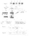
- the vehicle system 10 features a haptic apparatus 12 having the advantages summarized above.
- the haptic apparatus 12 includes an electronic control unit (ECU) or microcontroller 14 and at least one motor 16 operatively associated with the accelerator pedal 18. While the microcontroller 14 could be a separate module, this functionality could instead be incorporated into the powertrain or engine control module 20 instead.
- a transmission control module 20a is also shown to illustrate that separate engine and transmission control modules may be provided. Given that a driver can only respond so quickly to computer-based coaching feedback, the additional load due to the functionality of microcontroller 14 may be insignificant relative to other functions of the engine control module.
- microcontroller 14 is the Texas Instruments TMS470R1B1M 16/32-Bit RISC microcontroller chip. This microcontroller chip features one megabyte of flash memory and two Controller Area Network (CAN) controllers.
- the CAN bus protocol is used in many vehicle systems today. However, the haptic apparatus being disclosed is not limited to any particular bus structure or protocol.
- Figure 1 also shows a flash memory circuit 14a connected to the microcontroller 14, as other suitable microcontrollers may not be equipped with non-volatile memory that can be used for recording events and other data. Whether or not the functionality of the microcontroller 14 is integrated into the engine control module 20 or some other controller onboard the vehicle, the microcontroller will have the coaching method programmed into its associated memory.
- the microcontroller 14 is coupled to the powertrain control module 20 through an OBD-II data port interface 15.
- OBD-II refers to an automotive standard in the U.S. for onboard diagnostics that requires the provision of a standard 16-pin connector accessible in the vehicle's cabin generally below the steering wheel. DC power is even made available through this onboard connector. While a connection directly to the CAN bus onboard the vehicle is an alternative in an aftermarket embodiment, it should be appreciated that the standard OBD-II connector provides a simple and low-cost point of connection specifically designed to provide an appropriately isolated data port. It should also be noted that a similar data port exists in Europe under the European Onboard Diagnostic (EOBD) standard.
- EOBD European Onboard Diagnostic
- the OBD-II data interface 15, the microcontroller 14 and a motor driver circuit 17 are preferably mounted on a circuit board 21 that is housed in a module enclosure 22 with a mating OBD-II connector 23 at one end an output interface 24 at the other end. While the connector 23 is shown attached to the enclosure 22, it should be appreciated that the connector 23 could alternatively be coupled to the enclosure via a ribbon cable or the like.
- An example of a commercially available OBD-II interface product having a circuit board therein is the T16-002 interface from Multiplex Engineering, Inc. of Goleta, California.
- Elm Electronics of Toronto Canada also provides a ELM320 - OBD (PWM) to RS232 Interpreter circuit that forms the basis of several OBD-II data interfaces, such as the AlI-In-One scan tool from OBD Diagnostics, Inc. of Redondo Beach, California.
- the output interface 24 preferably includes a connector to provide a communication output, such as RS-232C connector 25.
- An RS-232C connection is typically used with OBD-II scan tools for connecting to a computer or a personal data assistant device like PDA 26. While a removable wired connection to PDA 26 is shown in Figure 2 , it should be appreciated that wireless communication may also be employed, such as through a Bluetooth transceiver available from AutoEnginuity, L. L. C.
- haptic apparatus 12 in Figure 2 may be packaged and sold as an aftermarket unit for quick and proper installation (with or without PDA 26), preferably at an authorized dealer.
- the motor 16 may be mounted at an appropriate location on the accelerator pedal itself, such as the back side thereof, or at any other location operatively associated with the accelerator pedal, so that the driver is able to receive haptic feedback through the accelerator pedal.
- the motor 16 may be secured to a stationary bracket 27 that forms part of the accelerator pedal assembly via an adhesive-backed plastic mounting clip 28.
- the motor driver circuit 17 is electrically coupled between the microcontroller 14 and the haptic motor 16. The motor driver circuit 17 is used to apply electrical power to and thereby energize the haptic motor 16 in response to an output signal from the microcontroller 14.
- a separate driver circuit 17 may be used to energize a haptic motor 34 for the brake pedal 36.
- the motor driver circuit 17 may be any suitable circuit capable of selectively applying sufficient electrical power to the haptic motor 16.
- An exemplary motor driver circuit is illustrated in Figure 15 of U.S. Patent No. 5,897,437 issued on April 27, 1999 to Nishiumi et al. , entitled "Controller Pack.”
- the goal of the motor 16 is to provide a sufficient magnitude of haptic feedback to be perceptible, but not distractive to the driver. Said another way, the goal is to inform the driver, not necessarily be such as to command the driver's immediate attention.
- a driver may react over time on an almost subconscious level to slightly release pressure on the accelerator pedal in response to a gentle vibration from motor 16.
- the vibration motor in a typical cellular phone, the motor 16 can be quite small and still very effective.
- vibration motors may be used for motor 16, such as vibrator motor 4SH3-0212B from China Jinlong Holdings Group or even a 1.5 to 3VDC motor (model 273- 223) from Radio Shack with an eccentric mass 29 attached to its rotor.
- Other types of vibration motors are based upon piezoelectric, solenoid or electromagnetic operation, such as the Alps Electric ForceReactor(TM) AF series short-vibration feedback device.
- the haptic apparatus being disclosed is not limited to vibration motors per se.
- Other tactile feedback or other sense-of-touch feedback actuators may be suitable for this application, providing that they do not adversely interfere with the operation of the accelerator pedal or cause the driver to overreact.
- a rapid toggling back and forth of the motor that adjusts the movement of the accelerator and brake pedal assembly can be perceived as a haptic signal to the driver without changing vehicle operation.
- a single motor may be used to provide haptic feedback through both the accelerator and brake pedals.
- the vehicle driver determines how much driving style guidance or coaching is provided by the haptic apparatus 12.
- a human-machine interface is coupled to microcontroller 14 in the form of a three-position selector switch 30.
- the switch 30 enables the driver to select between a normal mode of operation, an economy mode of operation and an even higher economy mode of operation. In the normal mode of operation, no haptic feedback need be provided by apparatus 12. In the higher economy mode of operation, haptic feedback will be provided to the driver that is best suited to achieving the highest practical fuel economy that can be achieved for the vehicle.
- the selector switch 30 is comprised an ITT Industries, Cannon C&K Rafix22QR illuminated rotary selector switch model number 1.30 242.136.
- This switch may be mounted to the instrument panel or any other suitable location that can be easily reached by the driver. It should also be appreciated that many other types of switches may be employed. For example, additional switch pole positions could be provided to provide more fine-tuning control for the driver, even to the extent of providing a continuously variable switch like that of the volume control on a radio. Alternatively, the operation of existing switches in the vehicle may be reprogrammed to provide the functionality of switch 30, such as the informational cluster 32 shown in Figure 3 .
- the cluster 32 includes a set of dash mounted buttons 38-42 and display 44.
- Such a cluster can be found in the 2006 Lincoln Mark LT pickup truck to display messages like those shown on display 44. These messages include ambient temperature, average fuel economy, the compass direction that the vehicle is heading, and the accumulated miles driven.
- Info button 38 By depressing Info button 38, the vehicle driver is able to cycle through a set of preprogrammed messages, such as the one illustrated.
- the Setup button 40 is used to make various preprogrammed selections, such as using English or metric units.
- the Reset button 42 is used to reset operations, such as the average fuel economy calculation.
- switch 30 may be added to the programming of cluster 32.
- one of the selections that may be made through the Setup button 40 would be to place the haptic apparatus 12 in either the fuel economy or higher economy mode of operation, or disable haptic coaching feedback in the normal mode of operation.
- the Reset button could then be used to restart calculations related to fuel economy messages to be displayed, as well as enable the entry of information by the driver. For example, when the vehicle is refueled, the driver could enter the approximate price of gasoline paid by selecting one of the prices programmed into the cluster (e.g., $2.5/g, $2.6/g and so forth). Then, the Info button 38 would be used to cycle through to one or more messages that convey visual feedback to the driver, such as shown on display 44a.
- the driver could be given the positive feedback that even though $3 /gallon was paid at the fuel pump, the apparatus 12 and coaching method has achieved an increase in fuel economy that effectively reduces the price paid.
- Other behavioral reinforcing messages could include an estimate of monthly or annual fuel cost savings, or even the money being saved per hour like a wage being earned through better driving habits.
- visual feedback is used to positively convey behavioral reinforcing messages, while haptic feedback is used to subtlety convey fuel economy limits that the driver really wants to know.
- FIG 4 shows another type of switch assembly 46 that may be used as an appropriate HMI.
- the unitary switch assembly 46 includes five momentary push buttons 48-56 mounted in a plastic housing 58.
- the unitary switch assembly 46 could be constructed from the type of keyless entry keypad used on many Ford vehicles with a change in the button labels.
- One such keypad example is Ford part no. 3L2Z-14A626-AA, which also features wireless RF communication and an adhesive-backed mounting.
- Buttons 48-52 correspond to the three positions on switch 30.
- buttons 54 and 56 could be used to provide additional intermediate fuel economy settings, they may alternatively be used to select either city or highway driving optimization in accordance with the coaching method. Even though the method shown in Figure 8 demonstrates how the apparatus 12 is able to discern that highway optimization should be used, some users may prefer to have the ability to instruct which optimization mode should be employed.
- a touch-screen display 60 in the vehicle could alternatively be employed to incorporate the functionality of the switch 30.
- the functionality of the switch 30 could also be incorporated into a voice command system for the vehicle or the steering wheel buttons 64 as well.
- the touch-screen display 60 could be used to provide visual feedback to the driver in addition to the haptic feedback, it should be appreciated that such visual feedback is not essential in every application. As in the case of display 60, all of the other optional elements of the vehicle system 10 are shown in phantom lines.
- ACC adaptive cruise control system
- ACC adaptive cruise control system
- An exemplary ACC system is disclosed in U.S. Patent No. 6,708,099 issued on March 16, 2004 and is assigned to a common assignee, entitled "Stop And Go Adaptive Cruise Control System”.
- the antilock braking system (ABS) 68 could be used to provide braking intensity information to the haptic apparatus 12.
- ABS antilock braking system
- braking force could be interpolated by monitoring the rate at which the vehicle is decelerating.
- haptic feedback could be provided once the vehicle comes to a stop.
- the motor 34 could provide a short vibration burst to indicate to the driver that a series of recent braking operations are consistent with an aggressive style of driving, rather than a conservative style of driving known to promote fuel efficiency and driving safety.
- the coaching method will ideally be tuned to the particular operating characteristics of the vehicle that contains apparatus 12. For example, the rate at which a Ford F-150 can accelerate efficiently may well be different than the rate that a Ford Fusion can accelerate efficiently.
- the coaching method may also be tuned during the operation of the vehicle itself with the availability of additional information. For example, if the position and route of the vehicle is known, it may be determined that the vehicle has turned onto an entrance ramp of a highway and that rapid acceleration would be appropriate. Haptic feedback would not be particularly beneficial in such a case. Situations like this may also interpolated without resort to external information, such as from a sustained demand for rapid acceleration from a relatively slow speed.
- FIG. 5 a graph of fuel economy over a range of speeds is shown. This graph was taken from an exemplary test run of a 2006 Lincoln Mark LT pickup truck using the average fuel economy readout capability of this vehicle. Very briefly, once the speed of the vehicle was stabilized, the average fuel economy calculator was reset and the value recorded when the fuel economy reading became constant within 0.1 mpg. As illustrated in Figure 5 , the steady state fuel economy of a vehicle varies with speed (all other variables being constant, such as wind direction and the air conditioning system being off). The best fuel economy for this test run was found to be at 40 mph. Given that many city streets in the U.S. have a 45 mph speed limit, 40 mph could provide the appropriate speed setting for city driving optimization and the maximum fuel economy mode of operation.
- 45 mph could provide the appropriate speed setting for city driving optimization and the intermediate fuel economy mode of operation.
- the microcontroller 14 would cause the motor 16 to turn on and send its haptic vibration coaching signal to the driver.
- the trigger threshold could be more or less than optimal speed threshold if it produces a reaction in the driver to seek the optimal speed.
- the best trigger threshold will be one that enables the driver to avoid inefficient vehicle operation.
- a residential driving optimization routine could also be added, if not considered too intrusive.
- the optimum speed for highway driving in this example is preferably 55 mph.
- 55 mph is the speed limit on many expressways in the U.S.
- an increase from 55 mph to 60 mph caused a 9.3% drop in fuel efficiency from the fuel efficiency level of 55 mph.
- an increase from 50 mph to 55 mph only caused a 3.8% drop in fuel efficiency.
- the optimal speed limit for highway driving may be determined at least in part by the slope of the change in fuel economy with speed.
- some vehicles will have more than one peak in fuel efficiency relative to steady-state speed.
- one peak may be available for determining the city driving speed threshold (e.g., 40 mph), while another peak may be available to help determine the highway driving speed threshold.
- every vehicle model has its own unique fuel efficiency characteristics or profile. Indeed, there can be fuel efficiency variations between vehicles of the same model, due to such factors as the choice of axle ratio and whether or not a roof rack is present. Furthermore, the fuel efficiency will be impacted by the amount of passenger and/or cargo load being carried, as well as other factors such as wind speed. These factors may require a change in one or more of the trigger thresholds that determine when coaching feedback is provided through apparatus 12. As illustrated in Figure 1 , the powertrain control module 20 and the transmission control module 20a (if separate) receive input from quite a number of sensors as they seek to achieve the best balance of performance and efficiency in response to the speed or acceleration demand from the driver, as expressed through the accelerator pedal.
- the microcontroller 14 may include a lookup table stored in its program memory in which trigger thresholds are determined by a plot of vehicle speed against the acceleration rate.
- engine load is also included as an input to microcontroller 14 to provide a more exact understanding of the fuel consumption rate of the engine.
- Engine speed is also preferably included, as engine fuel efficiency is typically mapped against engine speed and engine load during the engine calibration process.
- an input from the transmission is also preferred, such as the current transmission gear employed.
- FIG 6 a graphical illustration of an acceleration test procedure for fuel economy evaluation is shown.
- a vehicle is accelerated from zero to 45 mph, held briefly at 45 mph before coasting down and bringing the vehicle to a stop.
- Three fuel economy readings are taken during this process.
- Three levels of vehicle acceleration from this test procedure are shown in Figure 7 .
- the fastest acceleration results in the worst fuel economy, while the slowest acceleration results in the best fuel economy.
- most drivers may not wish to accelerate at very slow rate routinely.
- a beneficial acceleration rate is one, as shown in Figure 7 , which achieves fuel efficiency close to a very slow acceleration rate, yet is fast enough to be acceptable to most drivers. This rate may then be used as the acceleration threshold for the higher fuel economy mode of operation.
- This rate may also be determined by knowing when a powertrain event like the unlocking of a transmission torque converter will occur, so that the driver will not unknowingly cause powertrain events that decrease fuel economy.
- a greater acceleration rate threshold will be used for the fuel economy mode. This threshold should be selected to be below the level of acceleration (relative to vehicle speed) that would cause a kickdown of the transmission to a lower gear.
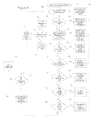
- step 106 the apparatus 12 is in the normal vehicle operation mode where haptic coaching feedback is not provided. Nevertheless, even if the driver has selected the normal mode of vehicle operation, the apparatus 12 is still preferably active.
- steps 106-110 a number of functions are performed, such as establishing baseline fuel efficiency values for the specific vehicle, detecting whether fuel efficiency is deteriorating over time, and recording all of the values that will be needed for future reference.
- the appropriate trigger thresholds will be chosen in step 112 to correspond to the fuel economy mode selected and the driving optimization regime or mode.
- an exemplary subroutine for this process is shown to the left. Specifically, for example, if the vehicle speed has exceeded a predetermined threshold for a predetermined amount of time, as shown in decision step 114, then the highway optimization mode 118 will be used. Additionally, it is possible for a driver to encounter stop-and-go traffic in either a city or highway driving condition. Accordingly, in one exemplary embodiment, a stop-and-go driving optimization mode 119 is preferably employed.
- a vehicle acceleration rate threshold is employed that will encourage the driver to leave at least a separation of five car lengths or more in the front.
- An appropriately slow acceleration rate and a greater vehicle separation will help avoid unnecessary braking force, as will be discussed in connection with Figure 10 .
- the next decision is whether the vehicle is currently accelerating or is likely to accelerate at a rate that exceeds a threshold determined by the microcontroller 14. Assuming that the answer from step 120 is yes, then the microcontroller 14 will energize or otherwise activate the motor 16 to provide haptic coaching feedback to the driver in step 122. The natural reaction of the operator will be to back off the accelerator pedal 18, thereby decreasing the rate of acceleration. This decrease in acceleration will be detected in successive reading cycles and once the microcontroller 14 has determined that the vehicle acceleration is acceptable or soon will be acceptable, then the motor 16 will be de-energized.
- the motor 18 could be energized for a predetermined short period of time initially and later energized with at least one longer period of time after a reasonable delay, if the vehicle has not slowed or stopped accelerating.
- the motor 18 could be energized for a short period of time when the threshold for the higher fuel economy mode is crosses and again at the higher threshold for the fuel economy mode if the vehicle continues to accelerate.
- different timing, amplification, frequency and pulsing techniques could be provided to achieve the coaching feedback needed.
- the microcontroller 14 will determine in step 124 whether the speed is too high relative to the fuel economy desired by the driver, as expressed through an input device like selector switch 30.
- the microcontroller 14 will energize the motor 16 to provide haptic feedback in step 126.
- This haptic feedback could also be different than that provided for an acceleration that is too rapid.
- the feedback for acceleration could be a continuous vibration
- the feedback for speed could be a pulsed vibration.
- a driver will not arrive to his or her destination any quicker by driving at a speed that is sufficiently high to cause poor fuel economy. For example, during a workday commute, a driver will typically encounter congestion on the expressway at some point that will render traveling at a higher speed up to that time pointless. As a specific example, assume that it is appropriate for the driver to travel at either 55 mph or 60 mph for 10 miles on an expressway before encountering stop-and-go traffic. By traveling at 60 mph, the driver will reach the stop-and-go traffic less than a minute quicker than he or she would by traveling at 55 mph.
- the microcontroller 14 could still be configured to provide such an estimate without route selection by the driver.
- a route/distance would have to be assumed given the time of travel and past trips at this time and day.
- the microcontroller 14 By recording trip start times, stop times, distances traveled, and periodic speeds, the microcontroller 14 will be able to deduce the most likely trip being made.
- the driver starts the vehicle's engine at 7:12 a.m. on a Monday. If the majority of trips made on Mondays between the hours of 6 a.m. and 8 a.m. are roughly 20 miles long, then average trip information from these 20 mile trips could be displayed to the driver (e.g., on display 44a in Figure 3 ), as well as the estimated travel times discussed above.
- the vehicle could automatically be pre-heated for a morning trip in the winter and/or pre-cooled for an afternoon trip in the summer in an environmentally-friendly way without requiring an instruction from the driver to do so.
- the information will be available for the microcontroller 14 to determine whether there is sufficient vehicle separation to promote fuel economy in step 128 and provide a haptic alert or push-back through the accelerator pedal if there is not (step 130).
- a healthy separation with respect to the vehicle in the front will enable the driver to slow down, but not have to stop in many driving circumstances.
- a pattern of rapid braking or rapid rate of deceleration
- a style of driving that promotes both driving safety and fuel economy.
- These diverging situations are illustrated by the two speed curves shown in Figure 9 .
- the microcontroller 14 may nevertheless determine that a pattern of insufficient separation is emerging. As illustrated in Figure 9 , a pattern of insufficient separation can be discerned from the amount of coastdown time permitted before a braking event and how rapidly the vehicle has then decelerated.
- the coastdown time can be determined from the change in vehicle speed.
- the microcontroller 14 may also use a change in vehicle speed to determine that a pattern of excessive braking is emerging (step 132) and provide haptic coaching feedback accordingly (step 134).
- a haptic reception conveys coaching feedback directly to (and need only be to) the driver without requiring a change in the driver's line of sight to be received.
- the microcomputer 14 will preferably recommend that the engine be turned off when a time threshold has been exceeded, as shown in steps 136 and 138.
- An exemplary time threshold may be two minutes. Given that the vehicle is stopped, this recommendation could be conveyed via display 44 or 60, such as "Turn off Engine?" Whether or not any of the thresholds discussed above have been crossed, steps 110 and 140 indicate that the variables needed in future reading cycles (e.g., vehicle speed and acceleration), will be recorded.
- step 142 indicates that the microcomputer 14 will preferably determine whether or not the vehicle speed has stabilized; that is, a situation in which it is clear that the driver is trying to maintain a steady vehicle speed. While the driver could optionally engage the vehicle's cruise control system at this point, step 144 shows the advantageous provision of a semi-cruise mode. Unlike a normal cruise control mode where the driver may remove his or her foot from the accelerator pedal 18, the semi-cruise mode need not be perceptible to the driver. In other words, the driver will still have his or her foot on the accelerator pedal 18 to the same extent, but the microcontroller 14 will use the cruise control system to prevent inadvertent pedal movements by the driver from adversely affecting fuel economy.
- Figure 10 shows one example of a lookup table that could be employed by the microcontroller 14.
- Figure 10 is intended to be generic and exemplary in nature, as each vehicle model will have its own particular fuel efficiency profile. In any event, it should be understood that fuel efficiency during acceleration is not constant across all appropriate vehicle speeds. While the fuel efficiency profile of a vehicle may be modeled from such standard calibration tools as a map of the fuel consumption rate against engine speed and load, a map of the transmission shift schedule against engine speed and vehicle speed, the vehicle itself may be tested to evaluate fuel efficiency across various speeds, acceleration rates and loads to determine one or more lookup tables of specific threshold values for microcontroller 14. It should also be noted that the 40 mph and 55 mph vehicle speeds are highlighted in Figure 10 and shown to be in slightly positive acceleration. This is to point out that the vehicle speed thresholds should be triggered in step 124 when the vehicle's speed is increasing.
Claims (15)
- Ein Gerät zur Bereitstellung von anweisender Rückmeldung an einen Fahrer eines Fahrzeugs, das dazu anhält, dass das Fahrzeug mit hoher Kraftstoffeinsparung gefahren wird, bestehend aus: einem haptischen Stellantrieb der operativ mit einer Gaspedalsteuereinheit des genannten Fahrzeugs verbunden ist, um dem genannten Fahrer Rückmeldung zu erstatten, gekennzeichnet durch eine Mensch-Maschine-Schnittstelle, die ermöglicht, dass der Fahrer zwischen einer Reihe von kraftstoffeinsparenden Einstellungen für Steigerung der Kraftstoffeinsparung wählen kann, und einer haptischen Steuerung, die so konfiguriert ist, dass sie anweisende Rückmeldung an den genannten Fahrer durch den genannten haptischen Stellantrieb liefert, wenn das genannte Fahrzeug zumindest eine einer Reihe von Geschwindigkeits- und Beschleunigungsschwellen in Reaktion auf die genannten Kraftstoffeinsparungseinstellungen der genannten Mensch-Maschine-Schnittstelle überschreitet.
- Ein Gerät entsprechend Anspruch 1, wobei die genannte haptische Steuerung unterschiedliche Geschwindigkeitsschwellen für Stadt- und Autobahnfahrsituationen umfasst.
- Ein Gerät entsprechend Anspruch 2, wobei die genannten Beschleunigungsschwellen zumindest teilweise von der Fahrzeuggeschwindigkeit abhängig sind.
- Ein Gerät entsprechend Anspruch 3, wobei zumindest eine der genannten Geschwindigkeitsschwellen für die genannten Stadt- und Autobahnfahrsituationen sich für jede der genannten Kraftstoffeinspareinstellungen der genannten Mensch-Maschine-Schnittstelle unterscheidet.
- Ein Gerät entsprechend einem der vorhergehenden Ansprüche, zu dem weiterhin ein haptischer Stellantrieb gehört, der operative mit einer Bremskontrolleinheit des genannten Fahrzeugs verbunden ist, und wobei die genannte haptische Steuerung weiterhin so konfiguriert ist, dass sie anweisende Rückmeldung in Reaktion auf Überschreitung von zumindest einer einer Reihe von mit Verlangsamung verbundener Schwellen liefert.
- Ein Gerät entsprechend Anspruch 5, wobei eine der mit Verlangsamung verbundenen Schwellen eine vorbestimmte Abrollzeit und eine andere der genannten mit Verlangsamung verbundenen Schwellen die Stärke der Bremsung anzeigt.
- Ein Gerät entsprechend einem der vorhergehenden Ansprüche, wobei die genannte haptische Steuerung mit einem Diagnostikport im genannten Fahrzeug verbunden ist.
- Ein Gerät entsprechend einem der vorhergehenden Ansprüche, wobei der genannte haptische Stellantrieb ein Vibrationsmotor ist, der an einem stationären Element der genannten Gaspedalkontrolleinheit befestigt ist.
- Ein Gerät entsprechend einem der vorhergehenden Ansprüche, wobei die genannte Mensch-Maschine-Schnittstelle eine Mehrfachnutzungsschnittstelle im genannten Fahrzeug ist.
- Ein Gerät entsprechend einem der vorhergehenden Ansprüche, wobei zur genannten Mensch-Maschine-Schnittstelle ein visuell wahrnehmbares Display gehört und die genannte haptische Steuerung weiterhin so konfiguriert ist, dass sie dem genannten Fahrer durch das genannte Display positive Rückmeldungen übermittelt.
- Ein Gerät entsprechend einem der vorhergehenden Ansprüche, wobei zur genannten Mensch-Maschine-Schnittstelle außerdem eine Einstellung ohne die genannte anweisende Rückmeldung gehört.
- Ein Aftermarkt-Bausatz zur Installation in eine Motorfahrzeug zur Implementierung eines Geräts entsprechend einem der vorhergehenden Geräte, wobei der Aftermarkt-Bausatz aus folgenden besteht: einem haptische Stellantrieb zur Bereitstellung von Rückmeldung an den Fahrzeugfahrer, wobei zum genannten haptischen Stellantrieb eine Befestigung zur Ermöglichung der Installation an der Gaspedalkontrolleinheit des genannten Fahrzeugs gehört; und einer haptischen Steuerung mit einer ersten Schnittstelle zum Anschluss an einen Diagnostikport des genannten Fahrzeugs und einer zweiten Schnittstelle zur Kommunikation mit einer Mensch-Maschine-Schnittstelle, wobei die genannten haptische Steuerung so konfiguriert ist, dass sie durch den genannten haptischen Stellantrieb anweisende Rückmeldung an den genannten Fahrer übermittelt, wenn das genannte Fahrzeug zumindest eine einer Reihe von Geschwindigkeits- und Beschleunigungsschwellen in Reaktion auf die genannten Kraftstoffeinsparungseinstellungen der genannten Mensch-Maschine-Schnittstelle überschreitet.
- Ein Aftermarkt-Bausatz entsprechend Anspruch 12, wobei sich die genannte Steuerung in einem Gehäuse befindet und die genannte Mensch-Maschine-Schnittstelle ein Schalter ist, zu dem auch eine Einstellung ohne anweisende Rückmeldung gehört.
- Ein Aftermarkt-Bausatz entsprechend Anspruch 12 oder 13, zu dem weiterhin ein zweiter haptischer Stellantrieb gehört, wobei der genannte haptische Stellantrieb eine Befestigung zur Ermöglichung der Installation an einer Bremskontrolleinheit des genannten Fahrzeugs gehört und die genannte haptische Steuerung weiterhin so konfiguriert ist, dass sie durch den genannten zweiten haptischen Stellantrieb anweisende Rückmeldung übermittelt, wenn das genannte Fahrzeug zumindest eine einer Reihe von mit Verlangsamung verbundenen Schwellen überschreitet.
- Ein Verfahren zur Übermittlung von anweisender Rückmeldung an einen Fahrer eines Fahrzeugs, das dazu anhält, dass das Fahrzeug mit hoher Kraftstoffeinsparung gefahren wird, bestehend aus folgenden Schritten: Bereitstellung von anweisender Rückmeldung durch einen haptischen Stellantrieb, der operativ mit einer Gaspedalkontrolleeinheit des genannten Fahrzeugs verbunden ist, wenn die Geschwindigkeit des genannten Fahrzeugs eine variable Geschwindigkeitsschwelle überschreitet, sowie Bereitstellung von anweisender Rückmeldung durch den genannten haptischen Stellantrieb, wenn die Beschleunigung des genannten Fahrzeugs eine variable Beschleunigungsschwelle überschreitet.
Applications Claiming Priority (2)
| Application Number | Priority Date | Filing Date | Title |
|---|---|---|---|
| US11/420,249 US7603228B2 (en) | 2006-05-25 | 2006-05-25 | Haptic apparatus and coaching method for improving vehicle fuel economy |
| PCT/US2007/069627 WO2007140232A2 (en) | 2006-05-25 | 2007-05-24 | Haptic apparatus and coaching method for improving vehicle fuel economy |
Publications (3)
| Publication Number | Publication Date |
|---|---|
| EP2059883A2 EP2059883A2 (de) | 2009-05-20 |
| EP2059883A4 EP2059883A4 (de) | 2010-11-03 |
| EP2059883B1 true EP2059883B1 (de) | 2013-03-13 |
Family
ID=38750572
Family Applications (1)
| Application Number | Title | Priority Date | Filing Date |
|---|---|---|---|
| EP07811931A Expired - Fee Related EP2059883B1 (de) | 2006-05-25 | 2007-05-24 | Haptische vorrichtung und trainingsverfahren zur verbesserung einer kraftfahrzeug-brennstoffökonomie |
Country Status (7)
| Country | Link |
|---|---|
| US (2) | US7603228B2 (de) |
| EP (1) | EP2059883B1 (de) |
| JP (1) | JP5427031B2 (de) |
| CN (1) | CN101460952B (de) |
| AU (1) | AU2007267562B2 (de) |
| BR (1) | BRPI0709308B1 (de) |
| WO (1) | WO2007140232A2 (de) |
Families Citing this family (155)
| Publication number | Priority date | Publication date | Assignee | Title |
|---|---|---|---|---|
| US7096852B2 (en) * | 2003-10-30 | 2006-08-29 | Immersion Corporation | Haptic throttle devices and methods |
| GB2469122A (en) * | 2009-04-02 | 2010-10-06 | Lysanda Ltd | Vehicle monitoring device to display to the driver information relating to fuel efficiency |
| DE102006012515B4 (de) * | 2006-03-18 | 2019-05-29 | Bayerische Motoren Werke Aktiengesellschaft | Kraftfahrzeug mit Hybridantrieb |
| US7603228B2 (en) * | 2006-05-25 | 2009-10-13 | Ford Global Technologies, Llc | Haptic apparatus and coaching method for improving vehicle fuel economy |
| US20070296268A1 (en) * | 2006-06-27 | 2007-12-27 | Shaw Schuyler S | Piezoelectric composite brake pedal feel emulating system |
| US7798578B2 (en) * | 2006-08-17 | 2010-09-21 | Ford Global Technologies, Llc | Driver feedback to improve vehicle performance |
| US8352146B2 (en) * | 2006-11-13 | 2013-01-08 | Ford Global Technologies, Llc | Engine response adjustment based on traffic conditions |
| JP4311451B2 (ja) * | 2007-01-16 | 2009-08-12 | トヨタ自動車株式会社 | 車両およびその制御方法 |
| FR2912979B1 (fr) * | 2007-02-27 | 2009-08-28 | Renault Sas | Dispositif de commande du mode de fonctionnement electrique d'un groupe motopropulseur hybride de vehicule automobile, par action sur la pedale d'accelerateur. |
| DE102007032310A1 (de) * | 2007-07-11 | 2009-01-15 | Deere & Company, Moline | Bedienvorrichtung |
| US8108136B2 (en) * | 2007-08-09 | 2012-01-31 | Ford Global Technologies, Llc. | Driver advisory system for fuel economy improvement of a hybrid electric vehicle |
| JP4687698B2 (ja) * | 2007-09-06 | 2011-05-25 | トヨタ自動車株式会社 | 省燃費運転支援装置 |
| US9726088B2 (en) * | 2007-10-30 | 2017-08-08 | Ford Global Technologies, Llc | System and method for obtaining an adjustable accelerator pedal response in a vehicle powertrain |
| DE102007054738A1 (de) * | 2007-11-16 | 2009-05-20 | Continental Teves Ag & Co. Ohg | Kraftfahrzeugenergiesparassistenzsystem |
| KR100941260B1 (ko) * | 2007-12-15 | 2010-02-11 | 현대자동차주식회사 | 오르간 타입 가속페달 장치 |
| EP2238009A1 (de) * | 2008-01-31 | 2010-10-13 | Continental Teves AG & Co. oHG | Fahrerassistenzsystem |
| US8116971B2 (en) * | 2008-06-26 | 2012-02-14 | Microsoft Corporation | Training a driver of a vehicle to achieve improved fuel economy |
| CN102067191A (zh) * | 2008-06-30 | 2011-05-18 | 罗姆股份有限公司 | 车辆的行驶信息记录装置 |
| US8374781B2 (en) * | 2008-07-09 | 2013-02-12 | Chrysler Group Llc | Method for vehicle route planning |
| KR101417116B1 (ko) * | 2008-10-22 | 2014-07-08 | 현대자동차주식회사 | 진동을 이용한 경제운전 안내 시스템 및 그 방법 |
| US20100106353A1 (en) * | 2008-10-28 | 2010-04-29 | Ford Global Technologies, Llc | Regenerative braking and charge flow state indication system for a hybrid electric vehicle |
| BRPI0914389A2 (pt) * | 2008-10-30 | 2015-10-20 | Ford Global Tech Llc | "veículo, método para avisar um condutor de um veículo e veículo automotivo" |
| NL2002184C2 (en) * | 2008-11-07 | 2010-05-10 | Verhey Van Wijk Beheer B V | Tactile speed control assist for car drivers. |
| SE533135C2 (sv) * | 2008-11-21 | 2010-07-06 | Scania Cv Abp | Bromsåterkopplingssystem |
| SE533139C2 (sv) * | 2008-11-21 | 2010-07-06 | Scania Cv Abp | System för fastställande av förmåga att förutse inbromsning |
| KR101168744B1 (ko) * | 2008-12-03 | 2012-07-26 | 한국전자통신연구원 | 정속 주행 시스템 및 그 방법 |
| JP5267095B2 (ja) | 2008-12-11 | 2013-08-21 | トヨタ自動車株式会社 | 走行状態評価装置 |
| US8706409B2 (en) | 2009-11-24 | 2014-04-22 | Telogis, Inc. | Vehicle route selection based on energy usage |
| DE102009007278A1 (de) * | 2009-02-03 | 2010-08-05 | Bayerische Motoren Werke Aktiengesellschaft | Energieoptimale Beschleunigungssteuerung für Kraftfahrzeuge |
| US8892341B2 (en) * | 2009-02-13 | 2014-11-18 | Inthinc Technology Solutions, Inc. | Driver mentoring to improve vehicle operation |
| US20100235076A1 (en) * | 2009-03-10 | 2010-09-16 | Microsoft Corporation | Estimation of fuel consumption from gps trails |
| JP4670978B2 (ja) * | 2009-03-11 | 2011-04-13 | 株式会社デンソー | 省燃費運転支援装置、プログラム |
| NL2003198C2 (en) * | 2009-07-14 | 2011-01-17 | Verhey Van Wijk Beheer B V | Tactile feedback on fuel economy to car driver. |
| JP2011047302A (ja) * | 2009-08-26 | 2011-03-10 | Ud Trucks Corp | 車両の省燃費運転システム |
| US8855880B2 (en) | 2009-10-05 | 2014-10-07 | Toyota Motor Engineering & Manufacturing North America, Inc. | Method and system for displaying braking information |
| US8886365B2 (en) * | 2009-10-30 | 2014-11-11 | Ford Global Technologies, Llc | Vehicle and method for advising driver of same |
| US8258934B2 (en) * | 2009-10-30 | 2012-09-04 | Ford Global Technologies, Llc | Vehicle and method of advising a driver therein |
| US8738228B2 (en) | 2009-10-30 | 2014-05-27 | Ford Global Technologies, Llc | Vehicle and method of tuning performance of same |
| JP5440101B2 (ja) * | 2009-11-04 | 2014-03-12 | アイシン・エィ・ダブリュ株式会社 | 案内制御装置、案内制御方法、及び案内制御プログラム |
| US9406229B2 (en) * | 2009-11-12 | 2016-08-02 | Gm Global Technology Operations, Llc | Travel lane advisor |
| KR101063680B1 (ko) * | 2009-11-25 | 2011-09-07 | 기아자동차주식회사 | 주행차량의 연비 게임 시스템 및 그 방법 |
| US8909414B2 (en) * | 2009-12-14 | 2014-12-09 | Volkswagen Ag | Three-dimensional corporeal figure for communication with a passenger in a motor vehicle |
| US8311722B2 (en) * | 2009-12-18 | 2012-11-13 | Chrysler Group Llc | Driver-based control system and method to improve fuel economy |
| US8463521B2 (en) * | 2009-12-23 | 2013-06-11 | Honda Motor Co., Ltd. | Vehicle driver coaching system and method |
| US8433473B2 (en) * | 2010-01-18 | 2013-04-30 | Ford Global Technologies, Llc | System and method for indicating an efficiency level of energy usage by an automotive vehicle |
| US8122843B2 (en) * | 2010-02-17 | 2012-02-28 | GAS Saver, LLC | Vehicle fuel efficiency monitor and signalling device |
| KR101182411B1 (ko) * | 2010-02-23 | 2012-09-12 | 자동차부품연구원 | 차량의 고연비 유지시스템 |
| US8543308B2 (en) | 2010-04-19 | 2013-09-24 | GM Global Technology Operations LLC | Systems and methods for communicating optimal driving information |
| SE535909C2 (sv) * | 2010-04-21 | 2013-02-12 | Scania Cv Ab | Metod och system för att bedöma en förares bromsbeteende |
| SE535868C2 (sv) * | 2010-04-21 | 2013-01-22 | Scania Cv Ab | Bedömningsmetod och system avseende acceleration |
| DE102010018753A1 (de) * | 2010-04-29 | 2011-11-03 | Dr. Ing. H.C. F. Porsche Aktiengesellschaft | Kraftfahrzeug |
| US9639688B2 (en) | 2010-05-27 | 2017-05-02 | Ford Global Technologies, Llc | Methods and systems for implementing and enforcing security and resource policies for a vehicle |
| DE102010029467A1 (de) | 2010-05-28 | 2011-12-01 | Ford Global Technologies, Llc | Verfahren und Vorrichtung zur Unterstützung eines Fahrers bei einer kraftstoffsparenden Fahrweise |
| US8190319B2 (en) * | 2010-06-08 | 2012-05-29 | Ford Global Technologies, Llc | Adaptive real-time driver advisory control for a hybrid electric vehicle to achieve fuel economy improvement |
| US20110309920A1 (en) * | 2010-06-21 | 2011-12-22 | Brooks James D | Tactile prompting system and method for tactually prompting an operator of a rail vehicle |
| BE1019390A4 (fr) * | 2010-06-28 | 2012-06-05 | Libotte Hugues | Dispositif autonome d'apprentissage et d'assistance a l'eco-conduite en temps reel. |
| SE537604C2 (sv) * | 2010-07-16 | 2015-07-21 | Scania Cv Ab | Metod för optimering av en parameter i ett motorforon baserad på en kostnadsfunktion, samt styrenhet anordnad att genomföra metoden |
| KR101199154B1 (ko) * | 2010-07-29 | 2012-11-12 | 기아자동차주식회사 | 하이브리드 차량의 변속 제어 시스템 및 그의 제어 방법 |
| DE102010062947A1 (de) * | 2010-12-13 | 2012-06-14 | Zf Friedrichshafen Ag | Verfahren zur Ansteuerung eines Retarders eines Kraftfahrzeuges |
| DE102010064058B4 (de) * | 2010-12-23 | 2016-06-16 | Robert Bosch Gmbh | Verfahren zum Betreiben eines Kraftfahrzeugs |
| US9452735B2 (en) | 2011-02-10 | 2016-09-27 | Ford Global Technologies, Llc | System and method for controlling a restricted mode in a vehicle |
| US8731736B2 (en) * | 2011-02-22 | 2014-05-20 | Honda Motor Co., Ltd. | System and method for reducing driving skill atrophy |
| AU2012246717A1 (en) * | 2011-02-25 | 2013-09-12 | Vnomics Corp. | System and method for in-vehicle operator training |
| US9371003B2 (en) * | 2011-03-31 | 2016-06-21 | Denso International America, Inc. | Systems and methods for haptic feedback control in a vehicle |
| US8522320B2 (en) | 2011-04-01 | 2013-08-27 | Ford Global Technologies, Llc | Methods and systems for authenticating one or more users of a vehicle communications and information system |
| GB201105830D0 (en) | 2011-04-06 | 2011-05-18 | Lysanda Ltd | Mass estimation model |
| US8630792B2 (en) | 2011-05-02 | 2014-01-14 | David B. Smith | Vehicle fuel cost-per-time display |
| US9428124B2 (en) * | 2011-05-03 | 2016-08-30 | Savannah Nuclear Solutions, Llc | Haptic seat for fuel economy feedback |
| US9171409B2 (en) | 2011-05-04 | 2015-10-27 | GM Global Technology Operations LLC | System and method for vehicle driving style determination |
| KR20120136922A (ko) * | 2011-06-10 | 2012-12-20 | 현대자동차주식회사 | 악셀페달의 답력을 이용한 자동변속 경보장치 및 이의 제어방법 |
| US8788113B2 (en) * | 2011-06-13 | 2014-07-22 | Ford Global Technologies, Llc | Vehicle driver advisory system and method |
| US10097993B2 (en) | 2011-07-25 | 2018-10-09 | Ford Global Technologies, Llc | Method and apparatus for remote authentication |
| GB2489057B (en) * | 2011-08-05 | 2013-03-06 | Enigma Electronics Com Ltd | Determining information relating to at least one characteristic of driving of a vehicle's driver |
| US8849519B2 (en) | 2011-08-09 | 2014-09-30 | Ford Global Technologies, Llc | Method and apparatus for vehicle hardware theft prevention |
| US9361271B2 (en) * | 2011-09-27 | 2016-06-07 | Wipro Limited | Systems and methods to enable eco-driving |
| US20130124009A1 (en) * | 2011-11-14 | 2013-05-16 | Ford Global Technologies, Llc | Method and system for managing personal settings on a vehicle |
| EP2594447A1 (de) * | 2011-11-16 | 2013-05-22 | C.R.F. Società Consortile per Azioni | Beurteilung eines Kraftfahrzeugfahrstils mit dem Ziel der Kraftstoffeinsparung |
| KR101327057B1 (ko) * | 2011-12-05 | 2013-11-07 | 현대자동차주식회사 | 차량의 경제운전 안내시스템 |
| US20130143181A1 (en) * | 2011-12-05 | 2013-06-06 | Ford Global Technologies, Llc | In-vehicle training system for teaching fuel economy |
| KR101338647B1 (ko) * | 2011-12-15 | 2013-12-06 | 현대자동차주식회사 | 촉각신호 발생장치가 적용된 가속페달 |
| JP5761004B2 (ja) * | 2011-12-15 | 2015-08-12 | アイシン・エィ・ダブリュ株式会社 | 評価表示システム、方法およびプログラム |
| JP2013126788A (ja) * | 2011-12-16 | 2013-06-27 | Denso Corp | 車両走行モード切替装置 |
| US8738262B2 (en) | 2011-12-30 | 2014-05-27 | Ford Global Technologies, Llc | Driving behavior feedback interface |
| US8682557B2 (en) | 2011-12-30 | 2014-03-25 | Ford Global Technologies, Llc | Driving behavior feedback interface |
| US8659409B2 (en) * | 2012-01-24 | 2014-02-25 | Ford Global Technologies, Llc | In-vehicle display for improving fuel economy |
| US20130245925A1 (en) * | 2012-03-19 | 2013-09-19 | Ford Global Technologies, Llc | Feedback system for engine auto stop inhibit conditions |
| SE537647C2 (sv) * | 2012-03-29 | 2015-09-08 | Scania Cv Ab | Förfarande och system för bedömning av förarbeteende vid bromsning av fordon |
| DE102012007388A1 (de) * | 2012-04-11 | 2013-10-17 | Gm Global Technology Operations, Llc | Warnsystem mit Warnsignalgeber eines Fahrzeugs und ein Verfahren zum Warnen von Insassen eines Fahrzeugs |
| US9275010B2 (en) * | 2012-04-12 | 2016-03-01 | Automatic Labs, Inc. | Method for improving fuel economy of an operated vehicle |
| DE102012008688B4 (de) * | 2012-04-28 | 2020-08-13 | Audi Ag | Verfahren zum Bestimmen eines zu erwartenden Verbrauchswertes eine Kraftwagens |
| US9569403B2 (en) | 2012-05-03 | 2017-02-14 | Ford Global Technologies, Llc | Methods and systems for authenticating one or more users of a vehicle communications and information system |
| JP5772712B2 (ja) * | 2012-05-14 | 2015-09-02 | 株式会社デンソー | 車両装置 |
| US9245428B2 (en) * | 2012-08-02 | 2016-01-26 | Immersion Corporation | Systems and methods for haptic remote control gaming |
| US9958272B2 (en) | 2012-08-10 | 2018-05-01 | Telogis, Inc. | Real-time computation of vehicle service routes |
| KR20140029834A (ko) * | 2012-08-30 | 2014-03-11 | 한국전자통신연구원 | 차량용 햅틱 피드백 장치 및 이를 이용한 방법 |
| US9366216B2 (en) | 2012-09-14 | 2016-06-14 | Ford Global Technologies, Llc | User interface for automatic start-stop system and method of controlling the same |
| US9050935B2 (en) | 2012-09-26 | 2015-06-09 | Ford Global Technologies, Llc | Assessment of driving behavior of a driver of a motor vehicle |
| JP2014075035A (ja) * | 2012-10-04 | 2014-04-24 | Denso Corp | 運転支援システム、及び、当該システムに用いられる車載機 |
| JP6070716B2 (ja) * | 2012-10-31 | 2017-02-01 | トヨタ自動車株式会社 | 車両の走行制御装置 |
| US8977430B2 (en) | 2012-12-26 | 2015-03-10 | Robert Bosch Gmbh | Electronic stability control system indicator |
| US9688246B2 (en) | 2013-02-25 | 2017-06-27 | Ford Global Technologies, Llc | Method and apparatus for in-vehicle alarm activation and response handling |
| US8947221B2 (en) | 2013-02-26 | 2015-02-03 | Ford Global Technologies, Llc | Method and apparatus for tracking device connection and state change |
| US9645970B2 (en) | 2013-02-28 | 2017-05-09 | Ford Global Technologies, Llc | Driver coaching system |
| US9141583B2 (en) | 2013-03-13 | 2015-09-22 | Ford Global Technologies, Llc | Method and system for supervising information communication based on occupant and vehicle environment |
| US9002536B2 (en) | 2013-03-14 | 2015-04-07 | Ford Global Technologies, Llc | Key fob security copy to a mobile phone |
| US9388750B2 (en) | 2013-03-15 | 2016-07-12 | Ford Global Technologies, Llc | System and method for optimizing availability of vehicle energy conserving modes |
| US8909404B2 (en) | 2013-03-15 | 2014-12-09 | Ford Global Technologies, Llc | Information display system and method |
| US9582024B2 (en) | 2013-04-05 | 2017-02-28 | Cts Corporation | Active vibratory pedal assembly |
| CN105556423B (zh) * | 2013-06-11 | 2019-01-15 | 意美森公司 | 用于基于压力的触觉效果的系统和方法 |
| US9174647B2 (en) * | 2013-06-25 | 2015-11-03 | Ford Global Technologies, Llc | Vehicle driver-model controller with energy economy rating adjustments |
| JP5803996B2 (ja) * | 2013-07-16 | 2015-11-04 | トヨタ自動車株式会社 | 省燃費運転診断装置 |
| US9174575B2 (en) * | 2013-09-24 | 2015-11-03 | Ford Global Technologies, Llc | Driver prompting braking system and method |
| DE102013016427B3 (de) * | 2013-10-02 | 2015-03-19 | Audi Ag | Verfahren zur Ermittlung einer effizienten Beschleunigung für eine vorzunehmende oder vorgenommene Fahrt mit einem Kraftfahrzeug |
| US9610955B2 (en) * | 2013-11-11 | 2017-04-04 | Smartdrive Systems, Inc. | Vehicle fuel consumption monitor and feedback systems |
| US9517771B2 (en) * | 2013-11-22 | 2016-12-13 | Ford Global Technologies, Llc | Autonomous vehicle modes |
| KR101583885B1 (ko) * | 2013-12-18 | 2016-01-08 | 현대자동차주식회사 | 엔진 열 관리 장치 및 방법 |
| CN104802805B (zh) * | 2014-01-28 | 2019-06-11 | 福特全球技术公司 | 带有交通流量提醒的车辆 |
| US9511778B1 (en) * | 2014-02-12 | 2016-12-06 | XL Hybrids | Controlling transmissions of vehicle operation information |
| US9327730B2 (en) * | 2014-02-17 | 2016-05-03 | Ford Global Technologies, Llc | Method to use GPS to optimize stopping distance to improve fuel economy |
| DE102015001818A1 (de) | 2014-02-19 | 2015-09-03 | Cummins Inc. | Fahrwiderstandsmanagement für Landfahrzeuge und/oder diesbezügliche Bedienerbenachrichtigung |
| US8892310B1 (en) | 2014-02-21 | 2014-11-18 | Smartdrive Systems, Inc. | System and method to detect execution of driving maneuvers |
| US9272621B2 (en) | 2014-04-24 | 2016-03-01 | Cummins Inc. | Systems and methods for vehicle speed management |
| US9835248B2 (en) | 2014-05-28 | 2017-12-05 | Cummins Inc. | Systems and methods for dynamic gear state and vehicle speed management |
| US9428195B1 (en) * | 2014-07-24 | 2016-08-30 | Lytx, Inc. | Back-end event risk assessment with historical coaching profiles |
| US9522597B2 (en) | 2015-03-03 | 2016-12-20 | Ford Global Technologies, Llc | Methods and system for providing vehicle performance feedback |
| US10249123B2 (en) | 2015-04-09 | 2019-04-02 | Ford Global Technologies, Llc | Systems and methods for mobile phone key fob management |
| EP3082081A1 (de) | 2015-04-16 | 2016-10-19 | Siemens Aktiengesellschaft | Verfahren und system zur haptischen rückmeldung von aktuellen energieverbrauchspreisen an den fahrer einer anlage oder maschine |
| GB2539676B (en) * | 2015-06-23 | 2020-11-25 | Bentley Motors Ltd | A method of controlling speed of a vehicle |
| KR101673355B1 (ko) | 2015-07-13 | 2016-11-16 | 현대자동차 주식회사 | 차량의 타력 주행 토크 제어시스템 및 이에 의한 제어방법 |
| US10094308B2 (en) | 2015-09-25 | 2018-10-09 | Cummins, Inc. | System, method, and apparatus for improving the performance of an operator of a vehicle |
| US9744905B1 (en) | 2015-10-30 | 2017-08-29 | State Farm Mutual Automobile Insurance Company | Systems and methods for notification of exceeding speed limits |
| SE539393C2 (en) * | 2015-12-04 | 2017-09-12 | Scania Cv Ab | Method and device for determining a measure of brake system usage during operation of a vehicle |
| JP6482010B2 (ja) * | 2017-04-25 | 2019-03-13 | 株式会社ユピテル | 車載機器接続用アダプタ |
| KR102322924B1 (ko) * | 2017-06-02 | 2021-11-08 | 현대자동차주식회사 | 차량 및 차량의 제어방법 |
| US10449916B2 (en) * | 2017-06-05 | 2019-10-22 | Paccar Inc. | Method for improving fuel economy by influencing driver behavior |
| US11355008B2 (en) * | 2017-06-30 | 2022-06-07 | Signify Holding B.V. | Lighting system with traffic rerouting functionality |
| US10317908B2 (en) | 2017-08-11 | 2019-06-11 | Toyota Motor Engineering & Manufacturing North America, Inc. | Peak efficiency recommendation and sharing |
| KR102170201B1 (ko) * | 2017-10-03 | 2020-10-27 | 구글 엘엘씨 | 센서 기반 검증을 통한 차량 기능 제어 |
| CN109808710A (zh) * | 2017-11-16 | 2019-05-28 | 宝沃汽车(中国)有限公司 | 车辆的控制方法、装置及具有其的车辆 |
| US11069234B1 (en) * | 2018-02-09 | 2021-07-20 | Applied Information, Inc. | Systems, methods, and devices for communication between traffic controller systems and mobile transmitters and receivers |
| GB2570908B (en) | 2018-02-09 | 2020-07-15 | Ford Global Tech Llc | A method of operating a vehicle |
| US11110939B2 (en) | 2018-03-19 | 2021-09-07 | Ford Global Technologies, Llc | Systems and methods for providing active driver feedback during electrified vehicle operation |
| US11551487B2 (en) * | 2018-07-02 | 2023-01-10 | Ford Global Technologies, Llc | Method and apparatus for vehicle-tuned diagnostics and reporting |
| CN109130873B (zh) * | 2018-07-24 | 2020-09-18 | 浙江亚太机电股份有限公司 | 一种利用毫米波雷达的电动车能量回收系统及智能电动车 |
| JP7256982B2 (ja) | 2018-12-28 | 2023-04-13 | スズキ株式会社 | 車両の走行制御装置 |
| DE202019000820U1 (de) | 2019-02-20 | 2019-03-25 | Kunststoffverarbeitung Hoffmann Gmbh | Haptisches-Signalisierungssystem in Türklinke |
| JP7189509B2 (ja) * | 2019-03-27 | 2022-12-14 | スズキ株式会社 | 車両の走行制御装置 |
| CN111907530B (zh) * | 2019-05-10 | 2021-12-03 | 广州汽车集团股份有限公司 | 一种基于驾驶风格识别的车辆加速响应时间调整方法及系统 |
| DE202019002153U1 (de) | 2019-05-16 | 2019-07-02 | Kunststoffverarbeitung Hoffmann Gmbh | lm Fahrzeugsitz eingelassenes haptisches Signalisierungssystem |
| JP7393730B2 (ja) | 2019-09-26 | 2023-12-07 | スズキ株式会社 | 車両の走行制御装置 |
| US11421999B2 (en) * | 2020-07-01 | 2022-08-23 | Global Traffic Technologies, Llc | Route selection using correction factors indicating phase interruptible traffic signals |
| KR102261527B1 (ko) * | 2021-01-14 | 2021-06-08 | 성균관대학교산학협력단 | 인휠 모터를 장착한 차량의 토크 벡터링 제어 장치 및 방법 |
| US11834059B2 (en) | 2021-01-21 | 2023-12-05 | Toyota Research Institute, Inc. | Locating smart shoe relative to pedal |
| JP2022138782A (ja) * | 2021-03-11 | 2022-09-26 | トヨタ自動車株式会社 | 交差点管制システム、交差点管制方法、及び、プログラム |
| CN113335182A (zh) * | 2021-07-21 | 2021-09-03 | 业成科技(成都)有限公司 | 车内安全系统及其操作方法 |
Family Cites Families (86)
| Publication number | Priority date | Publication date | Assignee | Title |
|---|---|---|---|---|
| US2122605A (en) | 1937-09-03 | 1938-07-05 | Aresee Company Inc | Automobile window sash mechanism |
| US2692980A (en) | 1952-03-29 | 1954-10-26 | Ernest C Platt | Engine condition signal arrangement for automotive vehicles |
| US2825418A (en) | 1955-10-17 | 1958-03-04 | Kershman Philip | Motor vehicle acceleration signal device |
| US4019475A (en) | 1974-06-06 | 1977-04-26 | Chrysler Corporation | Automobile acceleration control for fuel economy |
| DE2926024A1 (de) | 1979-06-28 | 1981-01-08 | Volkswagenwerk Ag | Verfahren und einrichtung zum betrieb einer brennkraftmaschine, insbesondere fuer ein fahrzeug |
| US5080207A (en) * | 1987-07-22 | 1992-01-14 | Zahnradfabrik Friedrichshafen Ag | Servo-assisted gear selector |
| US5113721A (en) | 1987-10-12 | 1992-05-19 | Auto Polly Gesellschaft M.B.H. | Method and apparatus for controlling a motor vehicle drive train |
| US5166879A (en) | 1990-12-03 | 1992-11-24 | Ford Motor Company | Load condition preemption of scheduled gearshifts in an automatic transmission |
| JP3336633B2 (ja) | 1992-07-30 | 2002-10-21 | 住友電気工業株式会社 | 電子制御ブレーキ装置および該ブレーキ装置におけるブレーキ特性設定方法 |
| JP3189498B2 (ja) * | 1993-06-15 | 2001-07-16 | 日産自動車株式会社 | 車両用定速走行装置 |
| US5734373A (en) * | 1993-07-16 | 1998-03-31 | Immersion Human Interface Corporation | Method and apparatus for controlling force feedback interface systems utilizing a host computer |
| DE4344369C2 (de) * | 1993-12-24 | 1997-12-11 | Daimler Benz Ag | Verbrauchsorientierte Fahrleistungsbegrenzung eines Fahrzeugantriebs |
| JP3336793B2 (ja) * | 1995-01-21 | 2002-10-21 | 三菱自動車工業株式会社 | 自動車の前方道路状況対応制御装置 |
| US5722302A (en) | 1995-08-09 | 1998-03-03 | Teleflex, Inc. | Adjustable pedal assembly |
| AU734018B2 (en) | 1995-10-09 | 2001-05-31 | Nintendo Co., Ltd. | Three-dimension image processing system |
| US5693876A (en) * | 1996-05-31 | 1997-12-02 | Freightliner Corporation | Fuel economy display for vehicles |
| DE19637210B4 (de) * | 1996-09-12 | 2007-05-24 | Siemens Ag | Antriebsstrangsteuerung für ein Kraftfahrzeug |
| US6092021A (en) * | 1997-12-01 | 2000-07-18 | Freightliner Corporation | Fuel use efficiency system for a vehicle for assisting the driver to improve fuel economy |
| US6089207A (en) | 1998-03-02 | 2000-07-18 | Cummins Engine Company, Inc. | Throttle control response selection system |
| JPH11305862A (ja) * | 1998-04-23 | 1999-11-05 | Naporekkusu:Kk | 自動車用ペダル |
| US6554088B2 (en) * | 1998-09-14 | 2003-04-29 | Paice Corporation | Hybrid vehicles |
| DE19860645A1 (de) * | 1998-12-29 | 2000-07-06 | Bosch Gmbh Robert | Verfahren und Vorrichtung zur Steuerung des Antriebsstrangs eines Fahrzeugs |
| US6289332B2 (en) | 1999-02-26 | 2001-09-11 | Freightliner Corporation | Integrated message display system for a vehicle |
| US6693622B1 (en) | 1999-07-01 | 2004-02-17 | Immersion Corporation | Vibrotactile haptic feedback devices |
| US6309031B1 (en) | 1999-12-14 | 2001-10-30 | Ford Global Technology, Inc. | Vehicle brake system with variable brake pedal feel |
| US6304809B1 (en) | 2000-03-21 | 2001-10-16 | Ford Global Technologies, Inc. | Engine control monitor for vehicle equipped with engine and transmission |
| DE10025492A1 (de) * | 2000-05-23 | 2001-12-13 | Daimler Chrysler Ag | Verfahren und Vorrichtung zur Rückmeldung des Fahrzustands eines Fahrzeugs an den Fahrer |
| US6655199B1 (en) | 2000-06-30 | 2003-12-02 | Rex L. Smith | Electronic foot pedal vehicle control system |
| US6470256B1 (en) | 2000-08-25 | 2002-10-22 | Visteon Global Technologies, Inc. | Fuel economizing cruise control |
| US6366848B1 (en) * | 2000-09-19 | 2002-04-02 | Volvo Trucks North America, Inc. | Engine control system for providing incentive to drivers |
| US6580973B2 (en) * | 2000-10-14 | 2003-06-17 | Robert H. Leivian | Method of response synthesis in a driver assistance system |
| US7565230B2 (en) * | 2000-10-14 | 2009-07-21 | Temic Automotive Of North America, Inc. | Method and apparatus for improving vehicle operator performance |
| US6909947B2 (en) * | 2000-10-14 | 2005-06-21 | Motorola, Inc. | System and method for driver performance improvement |
| US6925425B2 (en) * | 2000-10-14 | 2005-08-02 | Motorola, Inc. | Method and apparatus for vehicle operator performance assessment and improvement |
| US20020151297A1 (en) * | 2000-10-14 | 2002-10-17 | Donald Remboski | Context aware wireless communication device and method |
| US6480106B1 (en) * | 2000-12-11 | 2002-11-12 | Ford Global Technologies, Inc. | Rate of consumption gauge with variable rate of consumption limits |
| US6739212B2 (en) | 2000-12-22 | 2004-05-25 | Dura Global Technologies, Inc. | Adjustable pedal controller with obstruction detection |
| US6580977B2 (en) * | 2001-01-16 | 2003-06-17 | Ford Global Technologies, Llc | High efficiency fuel cell and battery for a hybrid powertrain |
| US6487477B1 (en) * | 2001-05-09 | 2002-11-26 | Ford Global Technologies, Inc. | Strategy to use an on-board navigation system for electric and hybrid electric vehicle energy management |
| US6507782B1 (en) * | 2001-05-14 | 2003-01-14 | Honeywell International Inc. | Aircraft control system for reaching a waypoint at a required time of arrival |
| GB0114424D0 (en) | 2001-06-13 | 2001-08-08 | Ricardo Consulting Eng | Improved vehicle control |
| JP2002370560A (ja) | 2001-06-14 | 2002-12-24 | Tokudaiji Jidosha Bunka Kenkyusho:Kk | 化石燃料を使用した車両の最適アクセル動作の車両内表示装置及びその方法 |
| FR2828155B1 (fr) | 2001-08-01 | 2003-11-28 | Peugeot Citroen Automobiles Sa | Dispositif d'alarme par vibration destine a informer un conducteur de vehicule automobile |
| DE60226817D1 (de) * | 2001-08-23 | 2008-07-10 | Nissan Motor | Fahrassistenzsystem |
| JP2003120339A (ja) | 2001-10-10 | 2003-04-23 | Toyota Motor Corp | アクセル反力制御装置 |
| JP3531640B2 (ja) * | 2002-01-10 | 2004-05-31 | 日産自動車株式会社 | 車両用運転操作補助装置 |
| US6708099B2 (en) * | 2002-01-17 | 2004-03-16 | Ford Global Technologies, Llc | Stop and go adaptive cruise control system |
| JP2003259504A (ja) * | 2002-03-06 | 2003-09-12 | Nissan Motor Co Ltd | 制動制御装置 |
| US6904823B2 (en) * | 2002-04-03 | 2005-06-14 | Immersion Corporation | Haptic shifting devices |
| DE10218012A1 (de) | 2002-04-23 | 2003-11-06 | Bosch Gmbh Robert | Verfahren und Vorrichtung zur Steuerung der Antriebseinheit eines Fahrzeugs |
| JP2003343305A (ja) | 2002-05-30 | 2003-12-03 | Toyota Motor Corp | クルーズコントロール装置 |
| JP4121318B2 (ja) * | 2002-06-26 | 2008-07-23 | 三菱電機株式会社 | 車両用のエンジン制御装置 |
| JP2004034938A (ja) * | 2002-07-08 | 2004-02-05 | Yazaki Corp | 居眠り運転防止装置及び車両運行情報収集装置 |
| DE10235165A1 (de) * | 2002-08-01 | 2004-02-19 | Robert Bosch Gmbh | Verfahren und Vorrichtung zur Signalisierung einer für den Betrieb eines Kraftfahrzeugs relevanten Imformation |
| JP3873876B2 (ja) * | 2002-12-06 | 2007-01-31 | 日産自動車株式会社 | 車両用運転操作補助装置およびその装置を備えた車両 |
| JP4012474B2 (ja) | 2003-02-18 | 2007-11-21 | 富士通株式会社 | シフト冗長回路、シフト冗長回路の制御方法及び半導体記憶装置 |
| DE102004010960A1 (de) | 2003-03-12 | 2004-10-14 | Continental Teves Ag & Co. Ohg | Verfahren zur Modifikation der Pedalcharakteristik in einem Bremssystem |
| ITBO20030198A1 (it) * | 2003-04-04 | 2004-10-05 | Ferrari Spa | Autoveicolo provvisto di un commutatore al volante per la selezione |
| JP2004314871A (ja) | 2003-04-18 | 2004-11-11 | Nissan Motor Co Ltd | アクセルペダル踏力制御装置 |
| DE10333962A1 (de) | 2003-07-25 | 2005-02-10 | Robert Bosch Gmbh | Verfahren zum Betreiben eines Fahrzeugs |
| DE10339647A1 (de) * | 2003-08-28 | 2005-03-24 | Robert Bosch Gmbh | Vorrichtung zur Fahrerwarnung |
| US6907325B1 (en) | 2003-09-24 | 2005-06-14 | Ford Global Technologies, Llc | Method of operating a hybrid electric vehicle to limit noise, vibration, and harshness |
| US7096852B2 (en) * | 2003-10-30 | 2006-08-29 | Immersion Corporation | Haptic throttle devices and methods |
| JP4367089B2 (ja) | 2003-10-30 | 2009-11-18 | 日産自動車株式会社 | アクセルペダル踏力制御装置 |
| JP4419531B2 (ja) * | 2003-11-20 | 2010-02-24 | 日産自動車株式会社 | 車両用運転操作補助装置および車両用運転操作補助装置を備える車両 |
| JP4254501B2 (ja) | 2003-11-20 | 2009-04-15 | 日産自動車株式会社 | 車両用運転操作補助装置および車両用運転操作補助装置を備えた車両 |
| US7013213B2 (en) | 2004-05-12 | 2006-03-14 | Ford Global Technologies, Llc | Method for controlling starting of an engine in a hybrid electric vehicle powertrain |
| US7499787B2 (en) * | 2004-10-07 | 2009-03-03 | Ford Global Technologies, Llc | Traction control system and method for a vehicle |
| JP4617172B2 (ja) * | 2005-02-17 | 2011-01-19 | 本田技研工業株式会社 | 移動体 |
| JP2006240368A (ja) * | 2005-03-01 | 2006-09-14 | Toyota Motor Corp | 車両用運転支援装置 |
| JP4539428B2 (ja) | 2005-05-10 | 2010-09-08 | 日産自動車株式会社 | 車両におけるアクセルペダル操作量に対する応答性補正 |
| JP2007076468A (ja) | 2005-09-13 | 2007-03-29 | Toyota Motor Corp | 車両の制御装置 |
| ATE390313T1 (de) * | 2005-10-19 | 2008-04-15 | Fiat Ricerche | Haptische anzeige umfassend ein gaspedal für ein kraftfahrzeug |
| JP5082243B2 (ja) | 2006-01-10 | 2012-11-28 | トヨタ自動車株式会社 | 車両用運転補助装置 |
| US7305300B2 (en) | 2006-02-13 | 2007-12-04 | Ford Global Technologies, Llc | Closed pedal deceleration control |
| US7487033B2 (en) * | 2006-05-22 | 2009-02-03 | Fuji Jukogyo Kabushiki Kaisha | Engine control apparatus |
| DE102007016618B4 (de) * | 2006-04-07 | 2017-07-13 | Fuji Jukogyo K.K. | Antriebskraft-Steuereinheit für ein Fahrzeug |
| US7603228B2 (en) * | 2006-05-25 | 2009-10-13 | Ford Global Technologies, Llc | Haptic apparatus and coaching method for improving vehicle fuel economy |
| US7646289B2 (en) * | 2006-06-27 | 2010-01-12 | Gm Global Technology Operations, Inc. | Fuel economy indicator lamp control system |
| US7798578B2 (en) * | 2006-08-17 | 2010-09-21 | Ford Global Technologies, Llc | Driver feedback to improve vehicle performance |
| US7609150B2 (en) * | 2006-08-18 | 2009-10-27 | Motorola, Inc. | User adaptive vehicle hazard warning apparatuses and method |
| BRPI0914389A2 (pt) * | 2008-10-30 | 2015-10-20 | Ford Global Tech Llc | "veículo, método para avisar um condutor de um veículo e veículo automotivo" |
| US8886365B2 (en) * | 2009-10-30 | 2014-11-11 | Ford Global Technologies, Llc | Vehicle and method for advising driver of same |
| US8258934B2 (en) * | 2009-10-30 | 2012-09-04 | Ford Global Technologies, Llc | Vehicle and method of advising a driver therein |
| US8190319B2 (en) * | 2010-06-08 | 2012-05-29 | Ford Global Technologies, Llc | Adaptive real-time driver advisory control for a hybrid electric vehicle to achieve fuel economy improvement |
| WO2018209039A1 (en) | 2017-05-11 | 2018-11-15 | Chem Link, Inc. | Click chemistry for sealants and adhesives |
-
2006
- 2006-05-25 US US11/420,249 patent/US7603228B2/en not_active Expired - Fee Related
-
2007
- 2007-05-24 AU AU2007267562A patent/AU2007267562B2/en not_active Ceased
- 2007-05-24 WO PCT/US2007/069627 patent/WO2007140232A2/en active Application Filing
- 2007-05-24 CN CN2007800175803A patent/CN101460952B/zh not_active Expired - Fee Related
- 2007-05-24 BR BRPI0709308A patent/BRPI0709308B1/pt not_active IP Right Cessation
- 2007-05-24 EP EP07811931A patent/EP2059883B1/de not_active Expired - Fee Related
- 2007-05-24 JP JP2009512296A patent/JP5427031B2/ja not_active Expired - Fee Related
-
2009
- 2009-10-07 US US12/575,262 patent/US8290697B2/en active Active
Also Published As
| Publication number | Publication date |
|---|---|
| JP5427031B2 (ja) | 2014-02-26 |
| US8290697B2 (en) | 2012-10-16 |
| WO2007140232A2 (en) | 2007-12-06 |
| CN101460952A (zh) | 2009-06-17 |
| JP2009539661A (ja) | 2009-11-19 |
| BRPI0709308A2 (pt) | 2011-07-05 |
| US7603228B2 (en) | 2009-10-13 |
| AU2007267562A1 (en) | 2007-12-06 |
| US20100030458A1 (en) | 2010-02-04 |
| BRPI0709308B1 (pt) | 2019-01-15 |
| US20070276582A1 (en) | 2007-11-29 |
| CN101460952B (zh) | 2012-06-13 |
| WO2007140232A8 (en) | 2009-02-12 |
| WO2007140232A3 (en) | 2008-08-21 |
| AU2007267562B2 (en) | 2012-06-21 |
| EP2059883A2 (de) | 2009-05-20 |
| EP2059883A4 (de) | 2010-11-03 |
Similar Documents
| Publication | Publication Date | Title |
|---|---|---|
| EP2059883B1 (de) | Haptische vorrichtung und trainingsverfahren zur verbesserung einer kraftfahrzeug-brennstoffökonomie | |
| US7798578B2 (en) | Driver feedback to improve vehicle performance | |
| US6580984B2 (en) | Method and device for supplying information to a driver of a vehicle | |
| CA2762807C (en) | Systems and methods for improving the efficiency of a vehicle | |
| CN102358189B (zh) | 加速器开度显示装置 | |
| US8401733B2 (en) | Optimized powertrain with route-learning feature | |
| EP2258588B1 (de) | Vorrichtung zur überwachung des fahrens eines fahrzeugs | |
| JP4495205B2 (ja) | エコ運転支援装置 | |
| JP4139314B2 (ja) | 運転作業負荷推定方法及びシステム | |
| CN103863119B (zh) | 车辆用显示装置 | |
| US20170213137A1 (en) | Systems and methods for predicting current and potential ranges of vehicles based on learned driver behavior | |
| US8548670B2 (en) | Fuel-saving driving diagnostic device, fuel-saving driving diagnostic system, travel control device, fuel-saving driving rating device, and fuel-saving driving diagnostic method | |
| CN101795919A (zh) | 燃料节省驾驶辅助设备 | |
| US20170341654A1 (en) | Adaptive drive control low-traction detection and mode selection | |
| KR20110091563A (ko) | 가속 거동 결정 | |
| US20100152956A1 (en) | Method and device for outputting driving information indicating an acceleration option that is optimal in terms of power consumption in a motor vehicle | |
| JP2009143355A (ja) | 車両用制御装置 | |
| KR20120020745A (ko) | 자동차용 클러스터의 정보 표시 방법 | |
| JP5387152B2 (ja) | 車両走行制御装置 | |
| EP4313663A1 (de) | Stufenlos anpassbares bremspedalkartensystem | |
| US20210387525A1 (en) | Method for improving the energy efficiency of a motor vehicle, motor vehicle, and computer-readable medium | |
| JP4828638B2 (ja) | エコ運転支援装置 | |
| JP4774463B2 (ja) | エコ運転支援装置 | |
| EP2857248B1 (de) | Verfahren zur Anzeige von Informationen im Zusammenhang mit effizientem Fahren eines Kraftfahrzeugs | |
| WO2014115268A1 (ja) | 減速走行制御装置 |
Legal Events
| Date | Code | Title | Description |
|---|---|---|---|
| PUAI | Public reference made under article 153(3) epc to a published international application that has entered the european phase |
Free format text: ORIGINAL CODE: 0009012 |
|
| 17P | Request for examination filed |
Effective date: 20081105 |
|
| AK | Designated contracting states |
Kind code of ref document: A2 Designated state(s): AT BE BG CH CY CZ DE DK EE ES FI FR GB GR HU IE IS IT LI LT LU LV MC MT NL PL PT RO SE SI SK TR |
|
| AX | Request for extension of the european patent |
Extension state: AL BA HR MK RS |
|
| DAX | Request for extension of the european patent (deleted) | ||
| RBV | Designated contracting states (corrected) |
Designated state(s): DE FR GB |
|
| A4 | Supplementary search report drawn up and despatched |
Effective date: 20101004 |
|
| GRAP | Despatch of communication of intention to grant a patent |
Free format text: ORIGINAL CODE: EPIDOSNIGR1 |
|
| GRAS | Grant fee paid |
Free format text: ORIGINAL CODE: EPIDOSNIGR3 |
|
| GRAA | (expected) grant |
Free format text: ORIGINAL CODE: 0009210 |
|
| AK | Designated contracting states |
Kind code of ref document: B1 Designated state(s): DE FR GB |
|
| REG | Reference to a national code |
Ref country code: GB Ref legal event code: FG4D |
|
| REG | Reference to a national code |
Ref country code: DE Ref legal event code: R096 Ref document number: 602007029088 Country of ref document: DE Effective date: 20130508 |
|
| PLBE | No opposition filed within time limit |
Free format text: ORIGINAL CODE: 0009261 |
|
| STAA | Information on the status of an ep patent application or granted ep patent |
Free format text: STATUS: NO OPPOSITION FILED WITHIN TIME LIMIT |
|
| 26N | No opposition filed |
Effective date: 20131216 |
|
| REG | Reference to a national code |
Ref country code: DE Ref legal event code: R097 Ref document number: 602007029088 Country of ref document: DE Effective date: 20131216 |
|
| REG | Reference to a national code |
Ref country code: FR Ref legal event code: PLFP Year of fee payment: 10 |
|
| REG | Reference to a national code |
Ref country code: FR Ref legal event code: PLFP Year of fee payment: 11 |
|
| PGFP | Annual fee paid to national office [announced via postgrant information from national office to epo] |
Ref country code: DE Payment date: 20170531 Year of fee payment: 11 |
|
| REG | Reference to a national code |
Ref country code: FR Ref legal event code: PLFP Year of fee payment: 12 |
|
| REG | Reference to a national code |
Ref country code: DE Ref legal event code: R079 Ref document number: 602007029088 Country of ref document: DE Free format text: PREVIOUS MAIN CLASS: G06F0019000000 Ipc: G16Z0099000000 |
|
| REG | Reference to a national code |
Ref country code: DE Ref legal event code: R119 Ref document number: 602007029088 Country of ref document: DE |
|
| PG25 | Lapsed in a contracting state [announced via postgrant information from national office to epo] |
Ref country code: DE Free format text: LAPSE BECAUSE OF NON-PAYMENT OF DUE FEES Effective date: 20181201 |
|
| PGFP | Annual fee paid to national office [announced via postgrant information from national office to epo] |
Ref country code: FR Payment date: 20190417 Year of fee payment: 13 |
|
| PGFP | Annual fee paid to national office [announced via postgrant information from national office to epo] |
Ref country code: GB Payment date: 20190430 Year of fee payment: 13 |
|
| GBPC | Gb: european patent ceased through non-payment of renewal fee |
Effective date: 20200524 |
|
| PG25 | Lapsed in a contracting state [announced via postgrant information from national office to epo] |
Ref country code: FR Free format text: LAPSE BECAUSE OF NON-PAYMENT OF DUE FEES Effective date: 20200531 Ref country code: GB Free format text: LAPSE BECAUSE OF NON-PAYMENT OF DUE FEES Effective date: 20200524 |