EP2044284B2 - Leiterförmiger isoliersteg für ein verbundprofil für fenster-, türen- und fassadenelemente und verbundprofil für fenster-, türen- und fassadenelemente - Google Patents
Leiterförmiger isoliersteg für ein verbundprofil für fenster-, türen- und fassadenelemente und verbundprofil für fenster-, türen- und fassadenelemente Download PDFInfo
- Publication number
- EP2044284B2 EP2044284B2 EP08734902.3A EP08734902A EP2044284B2 EP 2044284 B2 EP2044284 B2 EP 2044284B2 EP 08734902 A EP08734902 A EP 08734902A EP 2044284 B2 EP2044284 B2 EP 2044284B2
- Authority
- EP
- European Patent Office
- Prior art keywords
- profile
- insulating strip
- longitudinal direction
- clip
- door
- Prior art date
- Legal status (The legal status is an assumption and is not a legal conclusion. Google has not performed a legal analysis and makes no representation as to the accuracy of the status listed.)
- Active
Links
Images



Classifications
-
- E—FIXED CONSTRUCTIONS
- E06—DOORS, WINDOWS, SHUTTERS, OR ROLLER BLINDS IN GENERAL; LADDERS
- E06B—FIXED OR MOVABLE CLOSURES FOR OPENINGS IN BUILDINGS, VEHICLES, FENCES OR LIKE ENCLOSURES IN GENERAL, e.g. DOORS, WINDOWS, BLINDS, GATES
- E06B3/00—Window sashes, door leaves, or like elements for closing wall or like openings; Layout of fixed or moving closures, e.g. windows in wall or like openings; Features of rigidly-mounted outer frames relating to the mounting of wing frames
- E06B3/04—Wing frames not characterised by the manner of movement
- E06B3/263—Frames with special provision for insulation
- E06B3/26301—Frames with special provision for insulation with prefabricated insulating strips between two metal section members
-
- E—FIXED CONSTRUCTIONS
- E06—DOORS, WINDOWS, SHUTTERS, OR ROLLER BLINDS IN GENERAL; LADDERS
- E06B—FIXED OR MOVABLE CLOSURES FOR OPENINGS IN BUILDINGS, VEHICLES, FENCES OR LIKE ENCLOSURES IN GENERAL, e.g. DOORS, WINDOWS, BLINDS, GATES
- E06B3/00—Window sashes, door leaves, or like elements for closing wall or like openings; Layout of fixed or moving closures, e.g. windows in wall or like openings; Features of rigidly-mounted outer frames relating to the mounting of wing frames
- E06B3/04—Wing frames not characterised by the manner of movement
- E06B3/263—Frames with special provision for insulation
- E06B3/26301—Frames with special provision for insulation with prefabricated insulating strips between two metal section members
- E06B3/26303—Frames with special provision for insulation with prefabricated insulating strips between two metal section members with thin strips, e.g. defining a hollow space between the metal section members
-
- E—FIXED CONSTRUCTIONS
- E06—DOORS, WINDOWS, SHUTTERS, OR ROLLER BLINDS IN GENERAL; LADDERS
- E06B—FIXED OR MOVABLE CLOSURES FOR OPENINGS IN BUILDINGS, VEHICLES, FENCES OR LIKE ENCLOSURES IN GENERAL, e.g. DOORS, WINDOWS, BLINDS, GATES
- E06B3/00—Window sashes, door leaves, or like elements for closing wall or like openings; Layout of fixed or moving closures, e.g. windows in wall or like openings; Features of rigidly-mounted outer frames relating to the mounting of wing frames
- E06B3/04—Wing frames not characterised by the manner of movement
- E06B3/263—Frames with special provision for insulation
- E06B3/26301—Frames with special provision for insulation with prefabricated insulating strips between two metal section members
- E06B3/26305—Connection details
-
- E—FIXED CONSTRUCTIONS
- E06—DOORS, WINDOWS, SHUTTERS, OR ROLLER BLINDS IN GENERAL; LADDERS
- E06B—FIXED OR MOVABLE CLOSURES FOR OPENINGS IN BUILDINGS, VEHICLES, FENCES OR LIKE ENCLOSURES IN GENERAL, e.g. DOORS, WINDOWS, BLINDS, GATES
- E06B3/00—Window sashes, door leaves, or like elements for closing wall or like openings; Layout of fixed or moving closures, e.g. windows in wall or like openings; Features of rigidly-mounted outer frames relating to the mounting of wing frames
- E06B3/04—Wing frames not characterised by the manner of movement
- E06B3/263—Frames with special provision for insulation
- E06B2003/26349—Details of insulating strips
- E06B2003/2635—Specific form characteristics
- E06B2003/26352—Specific form characteristics hollow
-
- E—FIXED CONSTRUCTIONS
- E06—DOORS, WINDOWS, SHUTTERS, OR ROLLER BLINDS IN GENERAL; LADDERS
- E06B—FIXED OR MOVABLE CLOSURES FOR OPENINGS IN BUILDINGS, VEHICLES, FENCES OR LIKE ENCLOSURES IN GENERAL, e.g. DOORS, WINDOWS, BLINDS, GATES
- E06B3/00—Window sashes, door leaves, or like elements for closing wall or like openings; Layout of fixed or moving closures, e.g. windows in wall or like openings; Features of rigidly-mounted outer frames relating to the mounting of wing frames
- E06B3/04—Wing frames not characterised by the manner of movement
- E06B3/263—Frames with special provision for insulation
- E06B2003/26349—Details of insulating strips
- E06B2003/2635—Specific form characteristics
- E06B2003/26361—Openings, incisions or indents
-
- E—FIXED CONSTRUCTIONS
- E06—DOORS, WINDOWS, SHUTTERS, OR ROLLER BLINDS IN GENERAL; LADDERS
- E06B—FIXED OR MOVABLE CLOSURES FOR OPENINGS IN BUILDINGS, VEHICLES, FENCES OR LIKE ENCLOSURES IN GENERAL, e.g. DOORS, WINDOWS, BLINDS, GATES
- E06B3/00—Window sashes, door leaves, or like elements for closing wall or like openings; Layout of fixed or moving closures, e.g. windows in wall or like openings; Features of rigidly-mounted outer frames relating to the mounting of wing frames
- E06B3/04—Wing frames not characterised by the manner of movement
- E06B3/263—Frames with special provision for insulation
- E06B2003/26349—Details of insulating strips
- E06B2003/26387—Performing extra functions
-
- Y—GENERAL TAGGING OF NEW TECHNOLOGICAL DEVELOPMENTS; GENERAL TAGGING OF CROSS-SECTIONAL TECHNOLOGIES SPANNING OVER SEVERAL SECTIONS OF THE IPC; TECHNICAL SUBJECTS COVERED BY FORMER USPC CROSS-REFERENCE ART COLLECTIONS [XRACs] AND DIGESTS
- Y10—TECHNICAL SUBJECTS COVERED BY FORMER USPC
- Y10T—TECHNICAL SUBJECTS COVERED BY FORMER US CLASSIFICATION
- Y10T403/00—Joints and connections
- Y10T403/61—Side slide: elongated co-linear members
-
- Y—GENERAL TAGGING OF NEW TECHNOLOGICAL DEVELOPMENTS; GENERAL TAGGING OF CROSS-SECTIONAL TECHNOLOGIES SPANNING OVER SEVERAL SECTIONS OF THE IPC; TECHNICAL SUBJECTS COVERED BY FORMER USPC CROSS-REFERENCE ART COLLECTIONS [XRACs] AND DIGESTS
- Y10—TECHNICAL SUBJECTS COVERED BY FORMER USPC
- Y10T—TECHNICAL SUBJECTS COVERED BY FORMER US CLASSIFICATION
- Y10T403/00—Joints and connections
- Y10T403/70—Interfitted members
- Y10T403/7045—Interdigitated ends
Definitions
- the present invention relates to a ladder-shaped insulating web for a composite profile for window, door and facade elements and a composite profile for window, door and facade elements.
- Insulating bars for composite profiles for window, door and facade elements and composite profiles for window, door and facade elements are for example from DE 296 23 019 U1 ( EP 0 829 609 B1 ) DE 197 35 702 A1 .
- DE 298 21 183 U1 ( EP 1 004 739 B1 ) DE 199 56 415 C1 .
- EP 0 978 619 A2 and DE 198 53 235 A1 which discloses an insulating bar according to the preamble of claim 1, known.
- a Isoliersteg which consists of plastic and an embedded metal insert.
- the metal insert and the plastic have recesses, which lead to a ladder-like structure of the conductor bar.
- the metal insert serves to prevent a total failure of the insulating strip in case of fire.
- the recesses in the metal insert have the purpose of reducing the heat conduction.
- the EP 1 510 643 A1 and the DE 44 43 762 A1 reveal connecting bridges made of metal.
- a composite profile in particular a metal composite profile, in which the outer profile parts (e.g., outer shell and inner shell) are made of e.g. Metal are connected by means of one or more of plastic insulating webs.
- a relative movement in the longitudinal direction is limited or prevented by the high shear stiffness (expression of the rungs in width, thickness, length, number).
- the insulating bars are first made of a suitable material, e.g. manufactured by extrusion as profile parts with constant cross section over the length.
- the rungs, more specifically the recesses, are then produced by machining such as machining (e.g., milling), cutting (such as laser cutting, water jet cutting, etc.), punching, etc.
- machining e.g., milling
- cutting such as laser cutting, water jet cutting, etc.
- punching e.g., punching, etc.
- the reclaimed material can be recycled.
- the metal profile parts are firmly and thus captively connected to the insulating bar.
- cover profiles may e.g. clipped, glued, extruded, laminated, etc. It is also possible in addition to fill the spaces between the ladder rungs with a material having a lower coefficient of thermal conductivity than the material of the rungs.
- the function of such cover profiles, etc. on the one hand the protection against the ingress of moisture, on the other hand, the protection of the inner core. With the cover profiles, the moisture protection can be ensured.
- decorative elements can be attached.
- the cover profile can be made electrically conductive and thus accept the color of the metal profiles in the powder coating. Also a printing is possible.
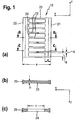
- insulating webs 10 extend the rungs 23 of the ladder-like Isoliersteg stresses 20 between the continuous longitudinal edges 21, 22 transversely to the longitudinal direction Z. These can also be slightly inclined (up to about 20 °) to the transverse direction.
- the sprouts can also have a curved shape. Preferably, but not necessarily, all sprouts have the same shape.
- the longitudinal edges or edges 21, 22 are for (in the longitudinal direction z) shear-resistant connection with profile parts 31, 32 (see Fig. 3 ) of the composite profile.
- the longitudinal edges or edges 21, 22 are formed as curling heads 25 or curl projections for curling in grooves of the profile parts 31, 32, which are each formed by a rolling hammer 33 and opposite wall portion 34.
- Other types of connections such as gluing, etc. are also possible.
- the rungs 23 have a width b in the longitudinal direction z, which is selected depending on the required transverse tensile strength and the required transverse stiffness and the material used and in the range of 0.5 to 10mm, preferably, 1mm to 5mm, more preferably 1mm to 3mm is up.
- the rungs In a cross-section perpendicular to the longitudinal direction, the rungs have a height (thickness) h (in the direction y) which is selected depending on the required transverse tensile strength and the required transverse rigidity and the material used and in the range of 0.5 mm to 10 mm, preferably 0.5mm to 5mm, more preferably 0.7mm to 2mm.
- the rungs 23 are arranged in the longitudinal direction z at regular intervals d between them, which distances are in the range of 1mm to 100mm, preferably 1mm to 50mm, more preferably 1mm to 5mm, and more preferably 1 to 3mm.
- First test results were obtained from ladder-type insulating bars with rungs which had a width b of 1 mm in the longitudinal direction of the insulating strip in a first embodiment and 3 mm in a second embodiment and in each case regular intervals d of about 3 mm in the longitudinal direction of the insulating bar ,
- the rungs had in the plan view in the direction transverse to the longitudinal direction of the Isolierstegs a length c of about 142mm long with an overall dimension a of the insulating bar in this direction of about 23mm.
- the Isolierstege showed values for the transverse tensile strength (train in the direction of connecting the connected by means of the insulating web profile parts, ie in Fig. 1 .
- Fig. 4 shows a third embodiment of an insulating web 10, which serves to illustrate the invention, with meandering rungs of the ladder-like structure in one Fig. 1 a) corresponding view.
- an anextrudierter cover (cover profile) 40 is provided to cover the spaces between the rungs. in a Fig. 1 c) corresponding view.
- the cover is formed integrally with the web.
- the cover profile is viewed in a cross section perpendicular to the longitudinal direction z as a lid on one side of the rungs (seen in the x direction) and extruded its free end (edge) is clipped on the other side of the rungs (seen in x-direction).
- the clip connection is designed so that the clipping takes place in the vertical direction (y-direction).
- the clip connection is made different so as to be clipped obliquely to the height direction (y direction), and a traction force in the transverse direction (x direction) holds the clip in engagement.
- the IsolierstegACS 20 on the rungs 23 with clip heads (male clip parts) 28 is provided. These are arranged so that in the vertical direction y on one side of a clip head 28 and on the other side two clip heads 28 are arranged.
- the single clip head 28 is arranged in the transverse direction x centered on the rung, while the other two clip heads are arranged on the other side with an identical distance from the center.
- the clip heads are in each case by a height h 3 with respect to the remaining surface of the rungs 23 of the Isoliersteg stresses 20 before.
- the sum of the thickness h 1 ) in the vertical direction y and twice the projection h 3 is preferably identical to the thickness of the curling heads 25 in the vertical direction y.
- a cover (cover profile) 40 is formed so that it has on one side three clip receptacles (female clip parts) 48, of which the two outer have the same distance as the two located on one side of Isoliersteg stressess 20 clip heads 28 and the third clip recording is arranged centrally between them.
- the width a 2 of the lid 40 in the transverse direction x is smaller than or equal to this width l 1 of the Isoliersteg Materialss 20th
- the cover has contact lips 42 formed on its edges running in the longitudinal direction Z in the transverse direction x.
- the clip receptacles (female clip parts) 48 have a distance h 4 from the bottom of the clip receptacle in the height direction y to the outermost point of the clip receptacle, which is smaller than the height h 3 of the clip heads 28.
- the lips 42 end in the vertical direction y at the height level of the clip recordings 48 or slightly higher (see also Fig. 7c) ).
- plastic with an E-modulus greater than 2000 N / mm 2 is used.
- Suitable plastics are polyamide, polyester or polypropylene, for example PA66.
- the thickness h 1 of the Isoliersteg Congress all embodiments is in the range of 1 mm to 50 mm, preferably 1 mm to 10 mm, more preferably 1 mm to 2 mm, more preferably 1.4 to 1.8 mm.
- the thickness h 2 of the cover is preferably less than or equal to the thickness of the associated Isoliersteg stressess.
- the in the Fig. 5 and 6 The embodiment shown is well suited for smaller values of a in the range of 8 to 20 mm, for example 14 mm.
- the thickness h 1 is then preferably 1.4 mm, for example.
- the embodiment according to Fig. 7 is well suited for values of a in the range of 20 to 40 mm, eg 32 mm. In this case, the preferred thickness h 1 is in the range of 1.5 to 1.8 mm.
- For the indicated widths and material thicknesses PA66 is preferred as the material.
- Fig. 8 a is shown in a plan view perpendicular to the longitudinal direction defined in terms of shear strength embodiment.
- the insulating web has a width a in the x direction in the range 10 mm ⁇ a ⁇ 100 mm.
- the insulating web has in the height direction (thickness direction) y through the material of the web passing through recesses 24.
- the shape of the recesses is substantially triangular in plan view, with corners having an inner radius of radius R.
- the height of the triangles in the transverse direction x is c. The triangles are arranged alternately. This means in the plan view in Fig.
- the insulating web has in height direction y a height (thickness) h over its entire width, except for the curling heads 25 on. The values are selected as follows. For Isolierstege with a ⁇ 22mm c is in the range of 7 to 10, preferably 8mm.
- the radius R is ⁇ 2mm, preferably ⁇ 1mm, more preferably 0.5mm.
- the radius serves to avoid a notch effect and also the formation of a kind of bending joint.
- the width b of the rungs is 1 to 3mm, preferably 2mm.
- c is in the range of 8 to 18mm, preferably 12mm.
- the height h in the vertical direction y is 1.2 to 2.4 mm, preferably 1.8 mm.
- the bridge is made of PA66GF25.
- Fig. 8c shows a modification of the sixth embodiment in cross section, in which the course of the web between the two curl heads is not rectilinear, as in Fig. 8b) is.
- Fig. 8d shows a seventh embodiment.
- the seventh embodiment differs from the sixth embodiment in that the recesses are not substantially triangular but substantially rectangular.
- the cross section is vertical to the longitudinal direction as in the Fig. 8b) or c) be shown.
- the dimensions for a, b, c, e or R to the sixth embodiment also apply to the seventh embodiment.
- the dimension d, ie the extent of the recesses in the longitudinal direction z is in the range of 3 to 8 mm, preferably 5 mm. This dimension d also applies to the preferred maximum extent of the triangular recesses in the sixth embodiment, even if the dimension d in Fig. 8 a) not shown.
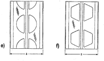
- Fig. 8e shows an eighth embodiment.
- the eighth embodiment differs from the sixth and seventh embodiments in that the recesses are circular with a diameter of dimension c.
- Fig. 8 f) shows a ninth embodiment, which differs from the sixth and seventh embodiments in that the recesses are hexagonal.
- the remaining details of the sixth and seventh embodiments apply, as applicable, also for the eighth and ninth embodiments.
- Fig. 9 shows in a) in plan view perpendicular to the longitudinal direction and in b) in cross section to the longitudinal direction of an insulating web with a so-called package construction.
- This package construction is intended to be used in a composite profile, as exemplified in Fig. 7c) shown in cross-section to be installed.
- the four curl heads 25 are thereby rolled into the corresponding four recordings, as is clear from the comparison with the Fig. 7 is readily apparent.
- Fig. 9b) upper insulating web portion 20a is in Fig. 7c) above and in Fig. 9b) lower Isolierstegteil 20b is in Fig. 7c) rolled up below.
- the two Isolierstegiers are connected by a clipped connection piece 20c so that on the one hand a shield against convection and radiation between the inside and outside of the composite profile is achieved, and on the other hand, a plurality of hollow chambers 20d are formed.
- the hollow chambers 20d are divided by a diagonal strut 20e of the connecting part 20c in the vertical direction y.
- recesses 24 may be formed with a width f in the transverse direction x and in a longitudinal extent d in the longitudinal direction z one or more Isolierstegmaschine 20a, 20b and / or the connecting part 20c.
- Isolierstegmaschine 20a and 20b shown have each still outwardly directed projections 20f, which can form receptacles for rubber seals and / or fitting parts. These are not an essential part of the embodiment shown.
- the number of recesses and the width and length of the recesses is not on the in Fig. 9 a) shown limited arrangement.
- FIG. 10 shows a so-called hollow chamber profile.
- a hollow chamber profile is located in the transverse direction x between the Einrollvorsprüngen 25 hollow chambers.
- Fig. 10d shows the cross section of a conventional hollow chamber profile.
- the difference is essentially that in the middle hollow chamber between the rungs 23, the wall is removed, so recesses 24 are formed.
- the recesses have a width g in the transverse direction x and a longitudinal extent d in the longitudinal direction z.
- the information on c of the sixth to ninth embodiments can also be used for g.
- a recess 24 is formed only on one side of the hollow chambers.
- the part of the hollow chamber profile in which one or more recesses 24 are formed is filled with a foam as filling material.
- This foam is preferably a PUR foam, which has a lower coefficient of thermal conductivity than the material formed to form the Isoliersteg stressess.
- the Fig. 11 a) to f) show modifications of the sixth to ninth embodiments in views with the same numbering a) to f), in each of which a projection 28 is formed, which protrudes substantially in the height direction y starting from the IsolierstegACS. Namely, this projection 28 serves to hinder convection and radiation.
- the height of the projection 8 in the height direction y is selected accordingly.
- dashed lines the installation of an insulating bar with such a projection 28 is indicated. If the in Fig. 7c) Upper insulating web has one or more corresponding projections 28, which seen in the transverse direction x overlap with the lower projection 28, then a particularly effective obstruction of the convection and radiation is achieved.
- the Fig. 12 b), c) and d) show modifications of Isolierstegen with two such protrusions 28th
- Suitable foams are foams made from thermosetting plastics such as PU of appropriate density, preferably foams of low density (0.01 to 0.3 kg / l).
Landscapes
- Engineering & Computer Science (AREA)
- Civil Engineering (AREA)
- Structural Engineering (AREA)
- Wing Frames And Configurations (AREA)
- Building Environments (AREA)
- Elimination Of Static Electricity (AREA)
- Door And Window Frames Mounted To Openings (AREA)
- Ladders (AREA)
Description
- Die vorliegende Erfindung bezieht sich auf einen leiterförmigen Isoliersteg für ein Verbundprofil für Fenster-, Türen- und Fassadenelemente und ein Verbundprofil für Fenster-, Türen- und Fassadenelemente.
- Isolierstege für Verbundprofile für Fenster-, Türen- und Fassadenelemente und Verbundprofile für Fenster-, Türen- und Fassadenelemente sind z.B. aus der
DE 296 23 019 U1 (EP 0 829 609 B1 ),DE 197 35 702 A1 ,DE 298 21 183 U1 (EP 1 004 739 B1 ),DE 199 56 415 C1 ,DE 198 18 769 A1 ,EP 0 978 619 A2 undDE 198 53 235 A1 , die einen Isoliersteg nach dem Oberbegriff des Anspruchs 1 offenbart, bekannt. - Aus der
DE 198 18 769 A1 ist ein Isoliersteg bekannt, der aus Kunststoff und einer eingebetteten Metalleinlage besteht. Die Metalleinlage und der Kunststoff weisen Aussparungen auf, die zu einer leiterartigen Struktur des Leitersteges führen. Die Metalleinlage dient zur Verhinderung eines Totalversagens des Isolierstegs im Brandfall. Die Aussparungen in der Metalleinlage haben den Zweck, die Wärmeleitung zu reduzieren. DieEP 1 510 643 A1 und dieDE 44 43 762 A1 offenbaren Verbindungsstege aus Metall. - Es ist eine Aufgabe der Erfindung, einen Isoliersteg (thermischen Trennsteg) für ein Verbundprofil, der ausreichend hohe Schubsteifigkeit bei verbesserter thermischer Trennung ermöglicht, und ein derart verbessertes Verbundprofil anzugeben.
- Diese Aufgabe wird gelöst durch einen Isoliersteg nach Anspruch 1 bzw. ein Verbundprofil nach Anspruch 5.
- Weiterbildungen der Erfindung sind in den Unteransprüchen angebeben.
- Es wird ein Verbundprofil, insbesondere ein Metallverbundprofil angeben, bei dem die außen gelegenen Profilteile (z.B. Außenschale und Innenschale) aus z.B. Metall mittels einem oder mehreren der Isolierstege aus Kunststoff verbunden sind. Eine Relativbewegung in Längsrichtung wird durch die hohe Schubsteifigkeit (Ausprägung der Sprossen in Breite, Dicke, Länge, Anzahl) begrenzt bzw. verhindert.
- Vorteilhaft werden die Isolierstege zuerst aus einem geeigneten Material z.B. durch Extrusion gefertigt als Profilteile mit konstantem Querschnitt über die Länge. Die Sprossen bzw. genauer die Ausnehmungen werden danach durch eine Bearbeitung wie eine spanende Bearbeitung (z.B. Fräsen), Schneiden (wie z.B. Laserschneiden, Wasserstrahlschneiden, etc.), Stanzen, usw. hergestellt. Das ausgenommene Material kann recycelt werden.
- Die Metallprofilteile werden fest und damit unverlierbar mit dem Isoliersteg verbunden.
- Zur Abdeckung der Zwischenräume zwischen den Sprossen sind die Isolierstege mit Abdeckprofilen versehen. Die Abdeckprofile können z.B. angeclipst, angeklebt, anextrudiert, auflaminiert, etc. werden. Es ist auch zusätzlich möglich, die Zwischenräume zwischen den Leitersprossen mit einem Material, das einen niedrigeren Wärmeleitungskoeffizienten als das Material der Sprossen aufweist, auszufüllen. Die Funktion solcher Abdeckprofile etc. ist einerseits der Schutz vor dem Eindringen von Feuchtigkeit, andererseits der Schutz des Innenkerns. Mit den Abdeckprofilen kann der Feuchtigkeitsschutz sichergestellt werden. Zusätzlich können dekorative Elemente angebracht werden. Z.B. kann das Abdeckprofil elektrisch leitfähig ausgeführt werden und damit bei der Pulverlackierung die Farbe der Metallprofile annehmen. Ebenfalls ist eine Bedruckung möglich.
- Ein Vorteil ist, dass die U-Werte (Wärmeleitungseigenschaften) der Isolierstege durch das Anbringen der Abdeckprofile/Füllungen, insbesondere der Abdeckprofile, nicht übermäßig verschlechtert werden.
- Weitere Merkmale und Vorteile folgen aus der Beschreibung von Ausführungsbeispielen anhand der Figuren. Von den Figuren zeigen:
-
Fig. 1 eine erste Ausführungsform eines Isolierstegs, die zur Erläuterung der Erfindung dient, in a) in Draufsicht, in b) im Querschnitt senkrecht zur Längsrichtung entlang der Linie B-B ausFig. 1a ), und in c) im Querschnitt senkrecht zur Längsrichtung entlang der Linie C-C ausFig. 1a ); -
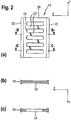
Fig. 2 eine zweite Ausführungsform eines Isolierstegs, die zur Erläuterung der Erfindung dient, mit anderer Sprossenbreite in derFig. 1 entsprechenden Ansichten; -
Fig. 3 eine Querschnittsansicht senkrecht zur Längsrichtung eines Isolierstegs beim Verbinden mit den Innen- und Außenprofilteilen eines Verbundprofils durch Einrollen; -
Fig. 4 eine dritte Ausführungsform eines Isolierstegs die zur Erläuterung der Erfindung dient, mit mäanderformigen Sprossen der leiterartigen Struktur in einerFig. 1 a) entsprechenden Ansicht; -
Fig. 5 eine vierte Ausführungsform eines Isolierstegs, die unter die Ansprüche fällt, mit anextrudiertem Deckel in einerFig. 1c ) entsprechenden Ansicht; -
Fig. 6 eine Modifikation der vierten Ausführungsform; -
Fig. 7 eine fünfte Ausführungsform eines Isolierstegs, die zur Erläuterung der Erfindung dient, in a) im Querschnitt des Isolierstegkörpers senkrecht zur Längsrichtung, in b) im Querschnitt eines anzuclipsenden Abdeckprofils senkrecht zur Längsrichtung, und in c) im Einbauzustand zwischen zwei Metallprofilen im Querschnitt senkrecht zur Längsrichtung; und -
Fig. 8 in den Ansichten a), b) eine sechste Ausführungsform eines Isolierstegs, die zur Erläuterung der Erfindung dient, in a) in Draufsicht senkrecht zur Längsrichtung und b) im Querschnitt senkrecht zur Längsrichtung, in Ansicht c) eine Modifikation der sechsten Ausführungsform im Querschnitt senkrecht zur Längsrichtung, in d) eine siebente Ausführungsform die zur Erläuterung der Erfindung dient in Draufsicht senkrecht zur Längsrichtung, in e) eine achte Ausführungsform, die zur Erlauterung der Erfindung dient, in Draufsicht senkrecht zur Längsrichtung, und in f) eine neunte Ausführungsform, die zur Erläuterung der Erfindung dient, in Draufsicht senkrecht zur Längsrichtung; -
Fig. 9 eine zehnte Ausführungsform eines Isolierstegs, die zur Erläuterung der Erfindung dient, in a) in Draufsicht senkrecht zur Längsrichtung und in b) im Querschnitt senkrecht zur Längsrichtung; -
Fig. 10 eine elfte Ausführungsform eines Isolierstegs, die zur Erläuterung der Erfindung dient, in a) in Draufsicht senkrecht zur Längsrichtung, in b) im Querschnitt senkrecht zur Längsrichtung, in c) in einer Modifikation der Querschnittsform senkrecht zur Längsrichtung, in d) einen Querschnitt ohne Ausnehmungen, in e) eine Modifikation der Ausführungsform aus b) mit Füllmaterial, und in f) eine Modifikation der Modifikation aus c) mit Füllmaterial; -
Fig. 11 Modifikationen der sechsten bis neunten Ausführungsformen in entsprechenden Ansichten; und -
Fig. 12 in a) eine Modifikation der Ausführungsform ausFig. 10 a) und c) , in b) und c) Modifikationen der Ausführungsformen ausFig. 8 und11 , und in d) eine Modifikation der Ausführungsformen ausFig. 10 . - Bei den in den
Fig. 1 ,2 gezeigten Isolierstegen 10 verlaufen die Sprossen 23 des leiterartig ausgebildeten Isolierstegkörpers 20 zwischen den durchgehenden Längskanten 21, 22 quer zur Längsrichtung Z. Diese können aber auch leicht geneigt (bis ca. 20°) zur Querrichtung verlaufen. Die Sprossen können auch eine gekrümmte Form aufweisen. Vorzugsweise aber nicht notwendigerweise weisen alle Sprossen dieselbe Form auf. - Die Längsränder oder -kanten 21, 22 sind zur (in Längsrichtung z) schubfesten Verbindung mit Profilteilen 31, 32 (siehe
Fig. 3 ) des Verbundprofils angepasst. In der gezeigten Ausführungsform sind die Längsränder oder -kanten 21, 22 als Einrollköpfe 25 oder Einrollvorsprünge ausgebildet für ein Einrollen in Nuten der Profilteile 31, 32, die jeweils von einem Einrollhammer 33 und gegenüberliegendem Wandabschnitt 34 gebildet werden. Andere Verbindungsarten wie Kleben etc. sind auch möglich. - In einer Draufsicht weisen die Sprossen 23 eine Breite b in Längsrichtung z, die abhängig von der geforderten Querzugfestigkeit und der geforderten Quersteifigkeit und dem verwendeten Material gewählt wird und im Bereich von 0,5 bis 10mm, vorzugsweise, 1mm bis 5mm, noch bevorzugter 1mm bis 3mm liegt, auf. In einem Querschnitt senkrecht zur Längsrichtung weisen die Sprossen eine Höhe (Dicke) h (in Richtung y) auf, die abhängig von der geforderten Querzugfestigkeit und der geforderten Quersteifigkeit und dem verwendeten Material gewählt wird und im Bereich von 0,5mm bis 10mm, vorzugsweise, 0,5mm bis 5mm, noch bevorzugter 0,7mm bis 2mm liegt. Die Sprossen 23 sind in Längsrichtung z mit regelmäßigen Abständen d zwischen sich angeordnet, welche Abstände im Bereich von 1mm bis 100mm, vorzugsweise 1mm bis 50mm, noch bevorzugter 1mm bis 5mm, und noch bevorzugter 1 bis 3 mm liegen.
- Natürlich sind auch andere Breiten, Dicken, Längen, und Abstände abhängig von den Anforderungen möglich.
- Erste Prüfergebnisse wurden von leiterartigen Isolierstegen mit Sprossen erhalten, die in der Draufsicht in Längsrichtung des Isolierstegs bei einer ersten Ausführung eine Breite b von 1mm und bei einer zweiten Ausführung von 3mm aufwiesen und in der Längsrichtung des Isolierstegs jeweils regelmäßige Abstände d von ca. 3mm aufwiesen. Die Sprossen hatten in der Draufsicht in der Richtung quer zur Längsrichtung des Isolierstegs eine Länge c von ca. 142mm lang bei einer Gesamtabmessung a des Isolierstegs in dieser Richtung von ca. 23mm. Die Isolierstege zeigten Werte für die Querzugfestigkeit (Zug in der Richtung des Verbindens der mittels des Isolierstegs verbundenen Profilteile, also in
Fig. 1 ,2 in Richtung x), die für beide Sprossenbreiten höher als für vergleichbare Profile nachDE 199 56 415 C1 waren, und für die Schubfestigkeit (gegenüber Verschieben der mittels des Isolierstegs verbundenen Profilteile in Längsrichtung z der Profilteile, also inFig. 1 ,2 in der Längsrichtung Z), die einfach durch Wahl der Sprossenbreite auf Werte unter oder über den Werten für vergleichbare Profile nachDE 199 56 415 C1 eingestellt werden konnten, so dass das Maß der Längsverschiebbarkeit bei sehr hoher Querzugfestigkeit einfach konfektionierbar ist. Diese Stege waren darauf ausgelegt, eine Längsverschieblichkeit zu gewährleisten, damit das sogenannte Bimetallproblem gemindert wird. -
Fig. 4 zeigt eine dritte Ausführungsform eines Isolierstegs 10, die zur Erläuterung der Erfindung dient, mit mäanderförmigen Sprossen der leiterartigen Struktur in einerFig. 1 a) entsprechenden Ansicht. - Bei der in
Fig. 5 gezeigten vierten Ausführungsform eines Isolierstegs 10, die unter die Ansprüche fällt, ist zur Abdeckung der Zwischenräume zwischen den Sprossen ein anextrudierter Deckel (Abdeckprofil) 40 vorgesehen. in einerFig. 1 c) entsprechenden Ansicht. Das Abdeckprofil ist einstückig mit dem Steg ausgebildet. Das Abdeckprofil ist in einem Querschnitt senkrecht zur Längsrichtung z gesehen als ein Deckel an einer Seite der Sprossen (in x-Richtung gesehen) anextrudiert und sein freies Ende (Rand) ist auf der anderen Seite der Sprossen (in x-Richtung gesehen) angeclipst. Die Clipsverbindung ist so ausgebildet, dass das Einclipsen in Höhenrichtung (y-Richtung) erfolgt. - In einer alternativen Ausführungsform, die unter die Ansprüche fällt und in
Fig. 6 gezeigt ist, ist die Clipsverbindung anderes gestaltet, so dass schräg zur Höhenrichtung (y-Richtung) eingeclipst wird und eine Zugkraft in Querrichtung (x-Richtung) hält den Clip im Eingriff. - Bei der in
Fig. 7 gezeigten fünften Ausführungsform, die zur Erläuterung der Erfindung dient, ist der Isolierstegkörper 20 auf den Sprossen 23 mit Clipsköpfen (männlichen Clipsteilen) 28 versehen. Diese sind so angeordnet, dass in Höhenrichtung y auf einer Seite ein Clipskopf 28 und auf der anderen Seite zwei Clipsköpfe 28 angeordnet sind. Dabei ist der einzelne Clipskopf 28 in Querrichtung x mittig auf der Sprosse angeordnet, während die beiden anderen Clipsköpfe auf der anderen Seite mit identischem Abstand von der Mitte angeordnet sind. - Die Clipsköpfe stehen jeweils um eine Höhe h3 gegenüber der übrigen Oberfläche der Sprossen 23 des Isolierstegkörpers 20 vor. Die Summe aus der Dicke h1) in Höhenrichtung y und zweimal dem Überstand h3 ist bevorzugt identisch zu der Dicke der Einrollköpfe 25 in Höhenrichtung y.
- Bei der fünften Ausführungsform ist ein Deckel (Abdeckprofil) 40 so ausgebildet, dass er an einer Seite drei Clipsaufnahmen (weibliche Clipsteile) 48 aufweist, von denen die beiden äußeren denselben Abstand wie die zwei auf einer Seite des Isolierstegkörpers 20 befindlichen Clipsköpfe 28 aufweisen und die dritte Clipsaufnahme mittig zwischen diesen angeordnet ist. Wie sich aus der
Fig. 7 ohne weiteres ergibt, können derart Deckel auf beiden Seiten des Isolierstegkörpers 20 angeclipst werden, ohne dass unterschiedlich ausgebildete Deckel notwendig sind. Der Isolierstegkörper 20 weist bei einen Gesamtbreite a(=a1) in Querrichtung X über eine Breite l1 in Querrichtung x eine im wesentlichen konstante Dicke h1 auf. Die Breite a2 des Deckels 40 in Querrichtung x ist kleiner oder gleich dieser Breite l1 des Isolierstegkörpers 20. - Der Deckel weist an seinen in Längsrichtung Z verlaufenden Rändern in der Querrichtung x ausgebildete Anlagelippen 42 auf. Die Clipsaufnahmen (weiblichen Clipsteile) 48 weisen einen Abstand h4 von dem Boden der Clipsaufnahme in Höhenrichtung y zu dem äußersten Punkt der Clipsaufnahme auf, der kleiner als die Höhe h3 der Clipsköpfe 28 ist. Die Lippen 42 enden in Höhenrichtung y auf dem Höhenniveau der Clipsaufnahmen 48 oder etwas höher (siehe auch
Fig. 7 c) ). - Als Material für den Isoliersteg wird vorteilhafterweise Kunststoff mit einem E-Modulwert größer 2000 N/mm2 verwendet. Geeignete Kunststoffe sind Polyamid, Polyester oder Polypropylen, zum Beispiel PA66.
- Die Dicke h1 der Isolierstegkörper aller Ausführungsformen liegt im Bereich von 1 mm bis 50 mm, vorzugsweise 1 mm bis 10 mm, noch bevorzugter 1 mm bis 2 mm, noch bevorzugter 1,4 bis 1,8 mm. Die Dicke h2 der Deckel ist bevorzugt kleiner oder gleich der Dicke des zugehörigen Isolierstegkörpers.
- Die in den
Fig. 5 und6 gezeigte Ausführungsform ist für kleinere Werte von a im Bereich von 8 bis 20 mm, beispielsweise 14 mm gut geeignet. Die Dicke h1 beträgt dann bevorzugt zum Beispiel 1,4 mm. Die Ausführungsform gemäßFig. 7 ist für Werte von a im Bereich von 20 bis 40 mm, z.B. 32 mm, gut geeignet. In diesem Fall liegt die bevorzugte Dicke h1 im Bereich von 1,5 bis 1,8 mm. Für die angegebenen Breiten und Materialstärken wird als Material PA66 bevorzugt. - Da die Isolierstegkörper aus Kunststoff bestehen, weisen keine Metalleinlage auf, d.h. sie sind ohne Metalleinlage ausgebildet.
- In
Fig. 8 a) ist in einer Draufsicht senkrecht zur Längsrichtung eine im Hinblick auf Schubfestigkeit definierte Ausführungsform dargestellt. Der Isoliersteg weist eine Breite a in x-Richtung im Bereich 10mm ≤ a ≤ 100mm auf. Der Isoliersteg weist in Höhenrichtung (Dickenrichtung) y durch das Material des Stegs hindurchgehende Ausnehmungen 24 auf. Die Form der Ausnehmungen ist in der Draufsicht im Wesentlichen dreieckförmig, mit Ekken mit einer Innenrundung mit einem Radius R. Die Höhe der Dreiecke in Querrichtung x ist c. Die Dreiecke sind alternierend angeordnet. Dies bedeutet, in der Draufsicht inFig. 8 a) ist jeweils eine Längsseite eines Dreiecks abwechselnd parallel nahe an der linken Seite, dann an der rechten Seite, dann wieder an der linken Seite, usw. angeordnet. Daraus folgt, dass auch die Spitzen alternierend angeordnet sind. Zwischen den Dreiecken befinden sich Sprossen 23, die eine Breite b senkrecht zu den sie begrenzenden Seiten der Dreiecke aufweisen. Die Dreiecke sind um ein Maß e von den jeweiligen Außenkanten in Querrichtung x entfernt. Daraus ergibt sich, dass a = c + 2e. Der Isoliersteg weist in Höhenrichtung y eine Höhe (Dicke) h über seine gesamte Breite, ausgenommen die Einrollköpfe 25 auf. Die Werte sind dabei wie folgt gewählt. Für Isolierstege mit a < 22mm liegt c im Bereich von 7 bis 10, bevorzugt 8mm. Der Radius R ist < 2mm, bevorzugt < 1mm, noch bevorzugter 0,5mm. Der Radius dient dazu, eine Kerbwirkung und auch die Bildung einer Art von Biegegelenk zu vermeiden. Die Breite b der Sprossen beträgt 1 bis 3mm, bevorzugt 2mm. - Für Stege mit a ≥ 22mm liegt c im Bereich von 8 bis 18mm, bevorzugt 12mm. Die Höhe h in Höhenrichtung y beträgt 1,2 bis 2,4mm, bevorzugt 1,8mm. Der Steg ist aus PA66GF25 ausgebildet.
-
Fig. 8 c) zeigt eine Modifikation der sechsten Ausführungsform im Querschnitt, bei der der Verlauf des Steges zwischen den beiden Einrollköpfen nicht geradlinig, wie inFig. 8 b) ist. -
Fig. 8 d) zeigt eine siebente Ausführungsform. Die siebente Ausführungsform unterscheidet sich von der sechsten Ausführungsform dadurch, dass die Ausnehmungen nicht im Wesentlichen dreieckig, sondern im Wesentlichen rechteckig sind. Der Querschnitt senkrecht zur Längsrichtung kann wie in denFig. 8 b) oder c) gezeigt sein. Die Maßangaben für a, b, c, e oder R zur sechsten Ausführungsform gelten auch für die siebente Ausführungsform. Das Maß d, d.h. die Ausdehnung der Ausnehmungen in Längsrichtung z liegt im Bereich von 3 bis 8mm, bevorzugt 5mm. Dieses Maß d gilt auch für die bevorzugte maximale Ausdehnung der dreieckigen Ausnehmungen in der sechsten Ausführungsform, auch wenn das Maß d inFig. 8 a) nicht gezeigt ist. -
Fig. 8 e) zeigt eine achte Ausführungsform. Die achte Ausführungsform unterscheidet sich von der sechsten und siebenten Ausführungsform dadurch, dass die Ausnehmungen kreisförmig mit einem Durchmesser mit dem Maß c sind.Fig. 8 f) zeigt eine neunte Ausführungsform, die sich von der sechsten und siebenten Ausführungsform dadurch unterscheidet, dass die Ausnehmungen sechseckig sind. Die übrigen Angaben zu der sechsten und siebenten Ausführungsform gelten, soweit anwendbar, auch für die achte und neunte Ausführungsform. -
Fig. 9 zeigt in a) in der Draufsicht senkrecht zur Längsrichtung und in b) im Querschnitt zur Längsrichtung einen Isoliersteg mit einer sogenannten Package-Konstruktion. Diese Package-Konstruktion ist dazu gedacht, in ein Verbundprofil, wie es beispielhaft inFig. 7 c) im Querschnitt gezeigt ist, eingebaut zu werden. Die vier Einrollköpfe 25 werden dabei in die entsprechenden vier Aufnahmen eingerollt, wie es aus dem Vergleich mit derFig. 7 ohne weiteres ersichtlich ist. Das inFig. 9 b) obere Isolierstegteil 20a wird dabei inFig. 7 c) oben und das inFig. 9 b) untere Isolierstegteil 20b wird dabei inFig. 7 c) unten eingerollt. Die beiden Isolierstegteile sind durch ein angeclipstes Verbindungsstück 20c so verbunden, dass einerseits eine Abschirmung gegen Konvektion und Strahlung zwischen Innen- und Außenseite des Verbundprofils erzielt wird, und dass andererseits mehrere Hohlkammern 20d gebildet werden. Die Hohlkammern 20d sind dabei durch eine Diagonalstrebe 20e des Verbindungsteils 20c in Höhenrichtung y unterteilt. Wie inFig. 9 a) gut zu erkennen ist, können Ausnehmungen 24 mit einer Breite f in Querrichtung x und in einer Längsausdehnung d in Längsrichtung z einen oder mehreren Isolierstegteile 20a, 20b und/oder dem Verbindungsteil 20c ausgebildet sein. Die inFig. 9 d) gezeigten Isolierstegteile 20a und 20b weisen jeweils noch nach außen gerichtete Vorsprünge 20f, die Aufnahmen für Gummidichtungen und/oder Beschlagsteile bilden können. Diese sind kein wesentlicher Bestandteil der gezeigten Ausführungsform. Die Zahl der Ausnehmungen und die Breite und Länge der Ausnehmungen ist nicht auf die inFig. 9 a) gezeigte Anordnung beschränkt. - Die in
Fig. 10 gezeigte Ausführungsform mit Modifikationen zeigt ein sogenanntes Hohlkammerprofil. Bei einem solchen Hohlkammerprofil befindet sich in Querrichtung x zwischen den Einrollvorsprüngen 25 Hohlkammern. InFig. 10d ) ist der Querschnitt eines herkömmlichen Hohlkammerprofils gezeigt. Wie sich aus dem Vergleich mit dem Querschnitt der elften Ausführungsform inFig. 10 b) ohne weiteres ergibt, besteht der Unterschied im Wesentlichen darin, dass in der mittleren Hohlkammer zwischen den Sprossen 23 die Wand entfernt ist, also Ausnehmungen 24 ausgebildet sind. Die Ausnehmungen weisen eine Breite g in Querrichtung x und eine Längsausdehnung d in Längsrichtung z auf. Insbesondere für Hohlkammerprofile mit einer Breite a von ≥ 25mm können die Angaben zu c der sechsten bis neunten Ausführungsform auch für g verwendet werden. Bei den Modifikationen inFig. 10 c) ist nur auf einer Seite der Hohlkammern eine Ausnehmung 24 ausgebildet. Entsprechend der Modifikationen, die inFig. 10 e) und f) gezeigt wird, wird der Teil des Hohlkammerprofils, in dem eine oder mehrere Ausnehmungen 24 ausgebildet sind, mit einem Schaum als Füllmaterial gefüllt. Dieser Schaum ist bevorzugt ein PUR-Schaum, der einen niedrigeren Wärmeleitungskoeffizienten als das zur Ausbildung des Isolierstegkörpers ausgebildete Material aufweist. - Die
Fig. 11 a) bis f) zeigen Modifikationen der sechsten bis neunten Ausführungsform in Ansichten mit gleicher Nummerierung a) bis f), bei denen jeweils ein Vorsprung 28 ausgebildet ist, der im Wesentlichen in Höhenrichtung y von dem Isolierstegkörper ausgehend vorsteht. Dieser Vorsprung 28 dient vornämlich zur Behinderung von Konvektion und Strahlung. Die Höhe des Vorsprungs 8 in Höhenrichtung y wird entsprechend gewählt. InFig. 7 c) ist unten gestrichelt der Einbau eines Isolierstegs mit einem solchen Vorsprung 28 angedeutet. Wenn der inFig. 7 c) obere Isoliersteg einen oder mehrere entsprechende Vorsprünge 28 aufweist, die in Querrichtung x gesehen mit dem unteren Vorsprung 28 überlappen, dann ist eine besonders effektive Behinderung der Konvektion und Strahlung erreicht. DieFig. 12 b), c) und d) zeigen Modifikationen von Isolierstegen mit zwei solchen Vorsprüngen 28. - Alle der in den
Fig. 8 bis 12 gezeigten Ausführungsformen sind bevorzugt mit anextrudierten Deckeln der inFig. 5 ,6 gezeigten Art vorgesehen. - Als Material für die Isolierstegkörper kommen Hart-PVC, PA, PET, PPT, PA/PPE, ASA. PA66 in Frage, und bevorzugt wird PA66GF25. Als Schäume kommen Schäume aus Duroplasten wie PU mit entsprechender Dichte in Frage, bevorzugt Schäume niedriger Dichte (0,01 bis 0,3 kg/l).
- Frühere Anwendungen von leiterartigen Profilen zielten darauf ab, eine niedrige Schubfestigkeit (hohe Längsbeweglichkeit) zu erzielen. In einer anderen Anwendung wurden Ausnehmungen nur vorgesehen, um bei einer bekanntermaßen sehr stark leitenden Metalleinlage die Wärmeleitung zu verringern.
- Bei den bevorzugten Ausführungsformen mit teilweise anextrudierten und auf der anderen Seite angeclipsten oder mit vollständig angeclipsten Deckeln ,jeweils zur Abdeckung der Ausnehmungen, hat sich insbesondere für die ganz oder teilweise angeclipsten Dekkel überraschenderweise herausgestellt, dass diese die sogenannten U-Werte, d.h. die Wärmetrennungseigenschaften der Isolierstege gegenüber nicht abgedeckten Versionen nur unwesentlich beeinflussen. So haben Versuche mit einem massiven Steg mit einem Querschnitt der in
Fig. 8 b) gezeigten Art, d.h. einem Steg ohne Ausnehmungen, der eine Breite von 25mm und eine Höhe h von 1,8mm und als Material PA26GF25 aufwies, einen U-Wert (W/m2K) von 2,4 ergeben. - Ein Isoliersteg der in
Fig. 8 d) gezeigten Art mit c = 8mm und d = 5mm und b = 2mm ergab ohne Abdekkung einen U-Wert 2,15 W/m2K. Ein entsprechender Steg mit gemäßFig. 7 angeclipsten Deckeln hatte einen U-Wert von 2,25 W/m2K. Die Messungen wurden in einer sogenannten "Hot-Box" durchgeführt, wobei als Ausgangssystem ein System mit 25mm breiten, flachen Isolierstegen eingesetzt wurde, die im Rahmen des Versuchs nicht getauscht wurden. In der Realität sollten die Verbesserungen der U-Werte daher noch besser sein. - Auch wenn der Grund dieses Effektes nicht ganz klar ist, so liegt er doch vermutlich in der Ausgestaltung der Clipsanschlüsse und damit des stark behinderten Wärmeübertragungsweges durch den Deckel.
- Für die in den
Fig. 9 ,10 gezeigten Ausführungsformen mit Hohlkammern, die bereits für Systeme mit sehr guten Isolierungseigenschaften eingesetzt werden, können diese Eigenschaften weiter verbessert werden. Das Verwenden von Konvektions- und/oder Strahlungsabschirmungsvorsprüngen 28 erhöht die Wirkung ebenfalls.
Claims (5)
- Isoliersteg (10) aus Kunststoff für ein Verbundprofil (1) für Fenster-, Türen- und Fassadenelemente, mit einem Isolierstegkörper (20), der sich in einer Längsrichtung (Z) erstreckt und wenigstens zwei Längskanten (21, 22), die in einer Querrichtung (X) um einen Abstand (a) voneinander getrennt sind, aufweist, die zur schubfesten Verbindung mit Profilteilen (31, 32) des Verbundprofils (1) als Einrollköpfe (25) für ein Einrollen in Nuten der Profilteile (31, 32) angepasst sind, der durch eine oder mehrere Wandungen des Isolierstegkörpers (20) in einer Höhenrichtung (Y) hindurchgehende Ausnehmungen (24), aufweist, die durch leitersprossenartige Stege (23) in Längsrichtung (Z) voneinander getrennt sind, dadurch gekennzeichnet, dass der Isoliersteg zur Abdeckung der Ausnehmungen mit einem in einem Querschnitt senkrecht zur Längsrichtung (Z) gesehen als ein Deckel an einer Seite der leitersprossenartigen Stege (25), in Querrichtung (X) gesehen, einstückig mit dem Steg ausgebildeten Abdeckprofil (40) vorgesehen ist, dessen freies Ende zum Anclipsen des Abdeckprofils (40) auf der in Querrichtung (X) gesehen anderen Seite der leitersprossenartigen Stege (23) ausgebildet ist.
- Isoliersteg nach Anspruch 1, der auf wenigstens einer Seite in Höhenrichtung (Y) vorstehende Clipsköpfe und/oder sich in Höhenrichtung (Y) erstreckende Vertiefungen aufweisende Clipsaufnahmen aufweist.
- Isoliersteg nach Anspruch 1 oder 2, bei dem das Abdeckprofil (40) in Querrichtung (X) gesehen auf einer Seite der Ausnehmungen (24) an den Isolierstegkörper (20) anextrudiert ist, und auf der in Querrichtung (X) gesehen anderen Seite der Ausnehmungen (24) das Abdeckprofil (40) und der Isolierstegkörper (20) zur Clipsverbindung angepasst sind.
- Isoliersteg nach einem der Ansprüche 1 bis 3, bei dem die Clipsverbindung so gestaltet ist, dass schräg zu der Höhenrichtung (Y) eingeclipst wird und eine Zugkraft in Querrichtung (X) den Clip in Eingriff hält.
- Verbundprofil für Fenster-, Türen- und Fassadenelemente mit wenigsten zwei Profilteilen (31, 32) und wenigstens einem Isoliersteg nach einem der Ansprüche 1 bis 4, bei dem die Profilteile (31, 32) durch Einrollen schubfest mit dem/den Isoliersteg(en) (10) verbunden sind.
Priority Applications (1)
| Application Number | Priority Date | Filing Date | Title |
|---|---|---|---|
| EP10176394.4A EP2256280A3 (de) | 2007-04-02 | 2008-03-31 | Leiterförmiger Isoliersteg für ein Verbundprofil für Fenster-, Türen- und Fassadenelemente |
Applications Claiming Priority (4)
| Application Number | Priority Date | Filing Date | Title |
|---|---|---|---|
| DE202007004935U DE202007004935U1 (de) | 2007-04-02 | 2007-04-02 | Leiterförmiger Isoliersteg für ein Verbundprofil für Fenster-, Türen- und Fassadenelemente und Verbundprofil für Fenster-, Türen- und Fassadenelemente |
| DE200720009106 DE202007009106U1 (de) | 2007-06-28 | 2007-06-28 | Leiterförmiger Isoliersteg für ein Verbundprofil für Fenster-, Türen- und Fassadenelemente und Verbundprofil für Fenster-, Türen und Fassadenelemente |
| DE202007016649U DE202007016649U1 (de) | 2007-04-02 | 2007-11-27 | Leiterförmiger Isoliersteg für ein Verbundprofil für Fenster-, Türen- und Fassadenelemente und Verbundprofil für Fenster-, Türen- und Fassadenelemente |
| PCT/EP2008/002543 WO2008119535A1 (de) | 2007-04-02 | 2008-03-31 | Leiterförmiger isoliersteg für ein verbundprofil für fenster-, türen- und fassadenelemente und verbundprofil für fenster-, türen- und fassadenelemente |
Related Child Applications (2)
| Application Number | Title | Priority Date | Filing Date |
|---|---|---|---|
| EP10176394.4A Division-Into EP2256280A3 (de) | 2007-04-02 | 2008-03-31 | Leiterförmiger Isoliersteg für ein Verbundprofil für Fenster-, Türen- und Fassadenelemente |
| EP10176394.4 Division-Into | 2010-09-13 |
Publications (4)
| Publication Number | Publication Date |
|---|---|
| EP2044284A1 EP2044284A1 (de) | 2009-04-08 |
| EP2044284B1 EP2044284B1 (de) | 2011-03-16 |
| EP2044284B8 EP2044284B8 (de) | 2011-04-20 |
| EP2044284B2 true EP2044284B2 (de) | 2018-02-28 |
Family
ID=39339359
Family Applications (2)
| Application Number | Title | Priority Date | Filing Date |
|---|---|---|---|
| EP08734902.3A Active EP2044284B2 (de) | 2007-04-02 | 2008-03-31 | Leiterförmiger isoliersteg für ein verbundprofil für fenster-, türen- und fassadenelemente und verbundprofil für fenster-, türen- und fassadenelemente |
| EP10176394.4A Withdrawn EP2256280A3 (de) | 2007-04-02 | 2008-03-31 | Leiterförmiger Isoliersteg für ein Verbundprofil für Fenster-, Türen- und Fassadenelemente |
Family Applications After (1)
| Application Number | Title | Priority Date | Filing Date |
|---|---|---|---|
| EP10176394.4A Withdrawn EP2256280A3 (de) | 2007-04-02 | 2008-03-31 | Leiterförmiger Isoliersteg für ein Verbundprofil für Fenster-, Türen- und Fassadenelemente |
Country Status (9)
| Country | Link |
|---|---|
| US (2) | US20100115850A1 (de) |
| EP (2) | EP2044284B2 (de) |
| JP (1) | JP5368424B2 (de) |
| CN (1) | CN101688421B (de) |
| AT (1) | ATE502182T1 (de) |
| CA (1) | CA2682644A1 (de) |
| DE (2) | DE202007016649U1 (de) |
| RU (1) | RU2472910C2 (de) |
| WO (1) | WO2008119535A1 (de) |
Families Citing this family (43)
| Publication number | Priority date | Publication date | Assignee | Title |
|---|---|---|---|---|
| DE102006059854B4 (de) * | 2006-12-15 | 2010-04-01 | Technoform Caprano Und Brunnhofer Gmbh & Co. Kg | Armiertes Kunststoffprofil für Fenster-, Türen- und Fassadenelemente |
| DE102006061035C5 (de) * | 2006-12-22 | 2014-09-04 | Technoform Bautec Holding Gmbh | Kunststoffprofil für Fenster-, Türen- und Fassadenelemente |
| DE202007016649U1 (de) * | 2007-04-02 | 2008-04-30 | Technoform Caprano Und Brunnhofer Gmbh & Co. Kg | Leiterförmiger Isoliersteg für ein Verbundprofil für Fenster-, Türen- und Fassadenelemente und Verbundprofil für Fenster-, Türen- und Fassadenelemente |
| ATE532933T1 (de) | 2008-06-18 | 2011-11-15 | Technoform Bautec Holding Gmbh | Verbundprofil für fenster-, türen-, oder fassadenelement mit vorbestimmten brandschutzeigenschaften und isoliersteg für ein verbundprofil mit brandschutzeigenschaften |
| IT1398965B1 (it) * | 2009-02-18 | 2013-03-28 | Eco S R L | Dispositivo per unione di due profilati di alluminio per la realizzazione di barre composite da utilizzare nella costruzione degli infissi a bassa trasmittanza termica. |
| ATE554257T1 (de) | 2009-10-28 | 2012-05-15 | Technoform Bautec Holding Gmbh | Verbundprofil für fenster-, türen- oder fassadenelemente mit vorbestimmten brandschutzeigenschaften und verbinder und anschlusselement dafür |
| DE102009054178B3 (de) * | 2009-11-21 | 2011-06-01 | Norsk Hydro Asa | Verfahren zur Herstellung eines wärmegedämmten Verbundprofils |
| US20110282633A1 (en) * | 2010-05-11 | 2011-11-17 | Thuan Bui | Component building system |
| US20110318094A1 (en) | 2010-06-29 | 2011-12-29 | Vincent Hensley | Strut for connecting frames |
| DE102011009359A1 (de) | 2011-01-25 | 2012-07-26 | Technoform Glass Insulation Holding Gmbh | Abstandshalterprofil und Isolierscheibeneinheit mit einem solchen Abstandshalterprofil |
| EP2532823A1 (de) * | 2011-06-09 | 2012-12-12 | Technoform Bautec Holding GmbH | Beschichtungsabdeckungsprofil für einen Isolierstreifen eines Verbundstoffprofils für ein Fenster-, Tür- oder Fassadenelemente |
| WO2013074532A1 (en) * | 2011-11-14 | 2013-05-23 | Oldcastle Buildingenvelope, Inc. | Method and system for thermal barrier installation |
| US8863469B2 (en) * | 2012-02-23 | 2014-10-21 | Heckmann Building Products Inc. | Thermal clip attachment apparatus for masonry anchors and methods thereof |
| DE102013204693A1 (de) | 2012-03-19 | 2013-09-19 | Harald Schulz | Dämmsteg für wärmegedämmte Metall-Kunststoff-Verbundprofile mit über der Dämmsteglänge veränderlicher Schubtragfähigkeit sowie wärmegedämmtes Verbundprofil |
| DE102012010900B4 (de) | 2012-06-01 | 2023-07-27 | Technoform Bautec Holding Gmbh | Verbundprofil für Fenster-, Türen oder Fassadenelemente und Isoliersteg für ein solches Verbundprofil |
| ES2592861T5 (es) | 2012-06-20 | 2020-04-30 | Technoform Bautec Holding Gmbh | Moldura aislante para un perfil compuesto para elementos de ventanas, de puertas o de fachadas y procedimiento para la fabricación de una moldura aislante de este tipo y perfil compuesto con una moldura aislante de este tipo |
| DE202012006555U1 (de) * | 2012-07-06 | 2012-08-09 | Technoform Bautec Holding Gmbh | Isoliersteg für ein Verbundprofil für Fenster-, Türen- oder Fassadenelemente und Verbundprofil für Fenster-, Türen- oder Fassadenelemente mit Isoliersteg |
| DE202012010135U1 (de) * | 2012-10-23 | 2012-11-22 | Technoform Bautec Holding Gmbh | Isoliersteg für ein Verbundprofil für Fenster-, Türen- oder Fasadenelemente und Verbundprofil für Fenster-, Türen- oder Fassadenelemente mit Isoliersteg |
| US9234380B2 (en) | 2013-03-13 | 2016-01-12 | Technoform Bautec North America, Inc. | Thermally insulating composite frame apparatus with slide-in thermal isolator and method for making same |
| BE1021797B1 (nl) | 2013-12-20 | 2016-01-19 | BLYWEERT ALUMINIUM, naamloze vennootschap | Kunststof isolatiesteeg, samengesteld profiel en raam die een dergelijke isolatiesteeg omvatten en werkwijze om een kader voor een raam te veraardigen |
| CN103758440B (zh) * | 2013-12-25 | 2016-05-04 | 泰诺风保泰(苏州)隔热材料有限公司 | 一种多腔体隔热条 |
| DE102014108264A1 (de) * | 2014-06-12 | 2015-12-17 | Ensinger Gmbh | Wärmeisolierendes Abstandhalterprofil |
| ES2786189T3 (es) * | 2014-12-18 | 2020-10-09 | Dormakaba Deutschland Gmbh | Sistema de paneles deslizantes |
| GB2535226B (en) * | 2015-02-13 | 2021-02-03 | Architectural & Metal Systems Ltd | Foam filled frame member |
| US9328549B1 (en) * | 2015-04-02 | 2016-05-03 | Special-Lite, Inc. | Frame with thermal barrier |
| DE102016121068A1 (de) * | 2016-02-29 | 2017-08-31 | SCHÜCO International KG | Verbundprofil für eine Tür, ein Fenster oder ein Fassadenelement sowie Verfahren zur Herstellung des Verbundprofils |
| EP3228794B1 (de) | 2016-04-05 | 2019-05-08 | Forster Profilsysteme AG | Profil für rahmen von türen, wandelementen oder fenstern |
| CN106193909B (zh) * | 2016-08-31 | 2018-03-16 | 江阴市凯希特节能材料科技有限公司 | 一种断桥铝合金型材隔热条 |
| DE102016119580A1 (de) * | 2016-10-13 | 2018-04-19 | Ensinger Gmbh | Kunststoffprofil für ein Metall-Kunststoff-Verbundprofil |
| DE102017107684A1 (de) * | 2017-04-10 | 2018-10-11 | Ensinger Gmbh | Isolierprofil, insbesondere für die Herstellung von Fenster-, Türen- und Fassadenelementen, sowie Verfahren zu seiner Herstellung |
| EP3396096B1 (de) * | 2017-04-28 | 2020-02-19 | RP Technik GmbH Profilsysteme | Verbundprofil sowie verfahren zur herstellung des verbundprofils |
| CN110914511A (zh) | 2017-05-31 | 2020-03-24 | 泰诺风保泰控股股份有限公司 | 用于窗户、门、立面和覆层元件的型材 |
| AU2018276403A1 (en) | 2017-05-31 | 2019-12-19 | Technoform Bautec Holding Gmbh | Profile for window, door, facade and cladding elements |
| EP3447228A1 (de) | 2017-08-25 | 2019-02-27 | Blyweert Aluminium SP. z.o.o. | Zwischenstück zur wärmekompensation |
| FR3073246B1 (fr) * | 2017-11-03 | 2020-11-20 | Groupe Liebot | Profile de rupture de pont thermique pour menuiserie de type porte ou fenetre et menuiserie equipee d'un tel profile |
| DE102018124779A1 (de) | 2018-10-08 | 2020-04-09 | Ensinger Gmbh | Verfahren zur Herstellung eines Isolierprofils |
| RU2749890C2 (ru) * | 2019-06-28 | 2021-06-18 | Игорь Васильевич Седов | Система алюминиевых профилей |
| BE1027906B1 (fr) | 2019-12-23 | 2021-07-29 | Van Beveren Sa | Ouvrant de porte ou de fenêtre composé de profilés composites et porte ou fenêtre comprenant un tel ouvrant |
| US11035167B1 (en) | 2020-03-03 | 2021-06-15 | Quaker Window Products Co. | Thermally enhanced extrudate for windows and doors |
| US11946313B2 (en) | 2020-09-04 | 2024-04-02 | Quaker Window Products Co. | Fenestration unit including slidable glass panels |
| EP4296463A1 (de) * | 2022-06-20 | 2023-12-27 | Arconic Technologies LLC | Integration von kommunikationsleitungen in profile |
| PT118084B (pt) * | 2022-07-06 | 2024-03-28 | Amorim Cork Composites S A | Perfil oco isolante para caixilharias de alumínio, caixilharia de alumínio compreendendo o referido perfil oco isolante e processo de produção de janela ou porta de alumínio |
| CN118292727A (zh) * | 2024-04-26 | 2024-07-05 | 上海添瑞门窗有限公司江苏分公司 | 一种拼接式中空铝型材及断桥铝结构 |
Family Cites Families (100)
| Publication number | Priority date | Publication date | Assignee | Title |
|---|---|---|---|---|
| DE7305385U (de) | 1973-06-14 | Hartmann W & Co | Zusammengepreßte warmedurchgangsunter brechende Metallrahmenprofile fur Tür und Fensterkonstruktionen | |
| DE7128512U (de) | 1971-10-21 | Hartmann W & Co | Zusammengesetzte, wärmedurchgangsunterbrechende Metallrahmenprofilteile, vorwiegend für Tür- und Fensterkonstruktionen | |
| DE7243199U (de) | 1973-03-29 | Hartmann W & Co | Zusammengepreßte, wärmedurchgangsunterbrechende Metallrahmenprofil teile für Tür- und Fensterkonstruktionen | |
| US2354485A (en) * | 1942-11-02 | 1944-07-25 | Extruded Plastics Inc | Composite article and element therefor |
| US2660275A (en) * | 1950-01-14 | 1953-11-24 | Gen Tire & Rubber Co | Gasket |
| DE1214375B (de) | 1960-02-05 | 1966-04-14 | Koller Metallbau Ag | Verbundprofilstab, insbesondere fuer Fenster- oder Tuerrahmen |
| DE1245568B (de) | 1961-12-21 | 1967-07-27 | Karl Steiner | Verbundprofilstab fuer Fensterfluegelrahmen, Fensterrahmen od. dgl. |
| DE1174483B (de) | 1962-03-29 | 1964-07-23 | Erbsloeh Julius & August | Verfahren und Vorrichtung zum Verbinden zweier Metallprofile, insbesondere Metall-fensterrahmen |
| DE1659428A1 (de) | 1967-08-17 | 1971-01-14 | Schenning Theodor Karl Peter | Metallprofil mit Isoliersteg aus Kunststoff |
| GB1271949A (en) | 1968-09-03 | 1972-04-26 | Cav Ltd | Regulators for dynamo electrical machines |
| US3554236A (en) * | 1968-11-26 | 1971-01-12 | Clifford A Rhodes | Stackable wiring duct |
| BE754446A (fr) | 1969-08-11 | 1971-01-18 | Keller Eberhard | Isolation calorifuge pour chassis de porte et de fenetre |
| DE1951517A1 (de) | 1969-10-13 | 1971-04-22 | Uhl Kg Geb | Verfahren zum Herstellen von waermeisolierenden Profilstaeben,vorzugsweise fuer Tuer-oder Fensterprofilrahmen |
| DE2033442C3 (de) | 1970-07-06 | 1974-06-12 | Julius & August Erbsloeh, 5600 Wuppertal | Verbundprofilrahmen für Fenster, Türen od.dgl |
| US4128934A (en) * | 1970-07-06 | 1978-12-12 | Firma Julius & August Erbsloh | Method of making a thermally insulated window frame |
| DE2100620A1 (de) | 1971-01-08 | 1972-07-27 | W. Hartmann & Co. Zweigniederlassung Nürnberg, 8500 Nürnberg | Zusammengesetzte wärmedurchgangsunterbrechende Metallrahmenprofilteile für Tür- und Fensterkonstruktionen |
| US3729045A (en) * | 1971-01-13 | 1973-04-24 | Adrian Inc | Molded screen frame |
| DE2103904A1 (de) | 1971-01-28 | 1972-08-10 | Alu-Therm W. Meyer & Co, 2104 Hamburg | Metall-Fensterrahmen aus dünnwandigen Blechprofilen |
| DE2122016C3 (de) | 1971-05-04 | 1973-10-04 | Gebrueder Uhl Kg, 7981 Vogt | Warmeisohertes Leichtmetall Ver bundprofil fur Fenster, Türen od dgl |
| DE2137145A1 (de) | 1971-07-24 | 1973-02-01 | Hartmann & Co W | Zusammengesetzte, waermedurchgangsunterbrechende metallrahmenprofilteile fuer tuer- und fensterkonstruktionen |
| DE2237245C3 (de) * | 1972-04-13 | 1979-10-11 | Goetz Metallbau Gmbh, 8360 Deggendorf | Isolationsprofil aus Kunststoff für ein Verbundprofil |
| CH564676A5 (de) * | 1972-05-08 | 1975-07-31 | Goetz Metallbau Gmbh | |
| DE2257670C3 (de) | 1972-11-24 | 1979-01-11 | W. Hartmann & Co Zweigniederlassung Nuernberg, 8500 Nuernberg | Fensterrahmen, Türrahmen o.dgl. mit wärmedurchgangsunterbrechender Zwischenlage |
| DE2300532C2 (de) | 1973-01-05 | 1974-11-21 | Schoeninger Gmbh, 8000 Muenchen | Wärmeisolierendes Verbundprofil für Fensterrahmen, Türrahmen od.dgl |
| DE2412317C2 (de) | 1973-03-20 | 1986-05-28 | Walter Schaffhausen Hallauer | Verfahren zur Herstellung eines Verbundprofils, insbesondere für Fenster- bzw. Türrahmen oder ähnliche Bauteile und isolierende Zwischenlage zum Ausführen des Verfahrens |
| DE2333420C3 (de) | 1973-06-30 | 1979-06-07 | W. Hartmann & Co Zweigniederlassung Nuernberg, 8500 Nuernberg | Fensterrahmen, Türrahmen o.dgl. aus zwei metallenen Teilrahmen und einer wärmedurchgangsunterbrechenden Zwischenlage |
| DE2522212C3 (de) | 1975-05-17 | 1984-04-19 | Volkmar 5429 Miehlen Heuser | Wärmeisolierender Rahmenschenkel für Fenster, Türen o.dgl. |
| DE2536666C3 (de) | 1975-08-18 | 1980-09-11 | Helmar Dr. 8530 Neustadt Nahr | Aus mindestens zwei Teilkörpern zusammengesetzter Körper |
| DE2608299C3 (de) | 1976-02-28 | 1984-04-19 | Plastic-Werk A. U. G. Scherer & Trier Ohg, 8626 Michelau | Verbundprofil, insbesondere für Fenster, Türen o.dgl. |
| DE2660436C3 (de) | 1976-02-28 | 1982-01-14 | Plastic-Werk A. U. G. Scherer & Trier Ohg, 8626 Michelau | Verbundprofil, insbesondere für Fenster, Türen, Fassaden o.dgl. |
| US4115972A (en) * | 1976-05-24 | 1978-09-26 | Giovanni Varlonga | Fixed and movable frame fixtures for doors and windows |
| FR2363720A1 (fr) * | 1976-08-31 | 1978-03-31 | Hasselbacher Wilhelm | Bande de liaison pour deux pieces en metal |
| DE2715007C3 (de) | 1977-04-04 | 1980-12-04 | Hasselbacher, Wilhelm, 8530 Neustadt | Verbundprofil, bestehend aus zwei Metallteilen und einem Isolationsprofil |
| US4057945A (en) * | 1976-10-19 | 1977-11-15 | Gerald Kessler | Insulating spacer for double insulated glass |
| DE2701942A1 (de) | 1977-01-19 | 1978-07-20 | Ulrich Kreusel | Waermedaemmendes verbundprofil |
| US4067163A (en) * | 1977-03-11 | 1978-01-10 | Hetman Frank W | Thermally insulated and connected window frame members and the method of making the same |
| US4272941A (en) * | 1977-04-04 | 1981-06-16 | Annemarie Hasselbacher | Thermally-insulating connecting elements for coupling two component parts, and also compound, thermally-insulating profile members and a process for their manufacture |
| DE2715010C3 (de) | 1977-04-04 | 1981-05-27 | Hasselbacher, geb. Schötz, Annemarie, 8630 Neustadt | Verbundprofil bestehend aus zwei Metallteilen und einem Isolationsprofil |
| FR2396198A1 (fr) | 1977-07-01 | 1979-01-26 | Hasselbacher Wilhelm | Dispositif de liaison a isolement thermique |
| DE2729882C3 (de) | 1977-07-01 | 1982-01-28 | Hasselbacher, geb. Schötz, Annemarie, 8530 Neustadt | Verbundprofil bestehend aus zwei zueinander parallelen Metallteilen und einem Isolationsprofil |
| DE2729909C3 (de) | 1977-07-01 | 1981-05-14 | Hasselbacher, geb. Schötz, Annemarie, 8630 Neustadt | Verbundprofil bestehend aus zwei parallelen Metallteilen mit einem einstückigen Isolationsprofil |
| DE2746434C3 (de) | 1977-10-15 | 1980-09-18 | Ritter Aluminium Gmbh, 7300 Esslingen | Verbundprofil für Fenster, Türen o.dgl. - aus zwei Metallprofilen und aus einem geschlossenen Hohlprofil aus wärmedämmendem Werkstoff |
| DE2755695C3 (de) * | 1977-12-14 | 1981-03-12 | Wieland-Werke Ag, 7900 Ulm | Wärmegedämmtes Verbundprofil für Fenster, Türen u.dgl. |
| US4184297A (en) * | 1978-06-05 | 1980-01-22 | Plaskolite, Inc. | Extruded plastic panel holding and jointing strips and window assemblies therewith |
| US4189880A (en) * | 1978-06-16 | 1980-02-26 | Gene Ballin | Combination mounting frame and film for a window |
| DE7903259U1 (de) | 1979-02-07 | 1979-06-13 | Schueco Heinz Schuermann Gmbh & Co, 4800 Bielefeld | Metall-profilstab |
| DE2908950A1 (de) | 1979-03-07 | 1980-09-18 | Schuermann & Co Heinz | Verfahren zum herstellen eines waermegedaemmten tuerfluegels sowie tuerfluegelrahmen |
| DE8220695U1 (de) | 1982-02-03 | 1983-02-10 | Hasselbacher, geb. Schötz, Annemarie, 8530 Neustadt | Waermeisolierende verbindungseinrichtung fuer metallprofile |
| EP0100991B1 (de) * | 1982-08-05 | 1987-06-10 | Otto Willert | Verbundprofil |
| US4548015A (en) * | 1983-07-25 | 1985-10-22 | Harold Switzgable | Thermally broken insulation support structure |
| DE3334332A1 (de) | 1983-09-22 | 1985-04-04 | Julius & August Erbslöh GmbH & Co, 5600 Wuppertal | Verfahren und hohlkoerper zur herstellung einer gleitfuehrung zwischen zwei relativ zueinander beweglichen bauteilen |
| DE3343687A1 (de) * | 1983-11-30 | 1985-06-05 | Schweizerische Aluminium Ag, Chippis | Metall-rahmenkonstruktion fuer fenster oder tueren |
| DE3418470A1 (de) | 1984-05-18 | 1985-11-21 | W. Hartmann & Co (Gmbh & Co), 2000 Hamburg | Langgestrecktes verbundelement zur bildung von vorgefertigten gebaeudeteilen |
| US4617772A (en) * | 1984-06-12 | 1986-10-21 | Jamestown Metal Marine Sales Inc. | Wall panel joiner |
| DE3469200D1 (en) | 1984-06-29 | 1988-03-10 | Tefo Ag | Assembling element with a first and a second flange, the latter being deflected from a reference line |
| DE3425135A1 (de) | 1984-07-07 | 1986-01-16 | Julius & August Erbslöh GmbH + Co, 5620 Velbert | Waermegedaemmtes verbundprofil |
| IT1208833B (it) * | 1985-09-19 | 1989-07-10 | Olivetti Synthesis Spa | Dispositivo di collegamento per pannelli |
| CA1290625C (en) * | 1985-11-07 | 1991-10-15 | Gunter Berdan | Spacer assembly for multiple glazed unit |
| US4788806A (en) * | 1986-03-20 | 1988-12-06 | Sease R Gregg | Assembly of molding strips adapted to mount flexible coverings on support surfaces |
| US4866895A (en) * | 1989-03-06 | 1989-09-19 | General Motors Corporation | Glass to sash channel attachment |
| DE3939968A1 (de) | 1989-12-02 | 1991-06-06 | Schueco Int Gmbh & Co | Verbundprofil, insbesondere fuer fenster, tueren und fassaden |
| US5675944A (en) * | 1990-09-04 | 1997-10-14 | P.P.G. Industries, Inc. | Low thermal conducting spacer assembly for an insulating glazing unit and method of making same |
| US5313761A (en) * | 1992-01-29 | 1994-05-24 | Glass Equipment Development, Inc. | Insulating glass unit |
| ES2076881B1 (es) | 1993-12-02 | 1998-09-01 | Maricurreina Lorenzo Diaz | Sistema modular para la formacion de cerramientos acristalados. |
| US5469683A (en) * | 1994-02-09 | 1995-11-28 | Kawneer Company, Inc. | Thermally insulating composite frame member with snap-in thermal isolator |
| DE9406691U1 (de) * | 1994-04-21 | 1994-06-09 | Skf Gmbh, 97421 Schweinfurt | Vorrichtung zur Verbindung von Lagerringen |
| DE4427682C2 (de) * | 1994-08-04 | 1996-12-12 | Ensinger Gmbh & Co | Verbundprofil für Rahmen von Fenstern, Türen, Fassadenelementen u. dgl. |
| DE4443762A1 (de) * | 1994-12-08 | 1996-06-13 | Schueco Int Kg | Rahmenwerk aus Metallprofilen in Brandschutzausführung für Fenster, Türen, Fassaden oder Glasdächer |
| CH690452A5 (de) | 1995-07-05 | 2000-09-15 | Kronenberger Ag | Isolationsvorrichtung zur thermischen Trennung von Leichtmetallprofilen im Fensterbau. |
| DE29621419U1 (de) * | 1995-12-13 | 1997-02-27 | W. Hartmann & Co (Gmbh & Co), 20459 Hamburg | Wärmegedämmtes Verbundprofil |
| US6038825A (en) * | 1996-02-21 | 2000-03-21 | The Lockformer Company | Insulated glass window spacer and method for making window spacer |
| DE19637858A1 (de) | 1996-09-17 | 1998-04-02 | Schueco Int Kg | Wärmegedämmtes Verbundprofil für Türen, Fenster oder Fassaden |
| JPH1122313A (ja) * | 1997-06-30 | 1999-01-26 | Niyuusuto:Kk | 断熱サッシ |
| DE19735702A1 (de) | 1997-08-16 | 1999-02-18 | Tegtmeier Metallbau | Isoliersteg |
| AU9734898A (en) * | 1997-09-25 | 1999-04-12 | Technoform Caprano + Brunnhofer Ohg | Profiled spacer for insulation glazing assembly |
| EP0945581A3 (de) * | 1998-03-25 | 2002-12-18 | Siegenia-Frank Kg | Beschlag für Fenster oder Türen |
| IL123980A (en) * | 1998-04-07 | 2000-10-31 | Arpal Aluminum Ltd | Blast resistant window framework and elements thereof |
| DE19818769C2 (de) | 1998-04-27 | 2001-07-12 | Ingbuero Dr Ing Harald Schulz | Wärmedämmleiste |
| DE29810183U1 (de) * | 1998-05-14 | 1999-09-23 | Technoform Caprano + Brunnhofer oHG, 34277 Fuldabrück | Verbundprofil für Rahmen von Fenstern, Türen, Fassadenelementen, u.dgl., IR-Reflexionsfolie insbesondere für dieses Verbundprofil und Verwendung der IR-Reflexionsfolie bei dem Verbundprofil |
| US6068720A (en) * | 1998-07-01 | 2000-05-30 | Edge Seal Technologies, Inc. | Method of manufacturing insulating glass units |
| DE19835439A1 (de) * | 1998-08-05 | 2000-02-17 | Pitscheider Ingenieurbuero Dr | Hohldämmleiste |
| DE19853235A1 (de) * | 1998-11-18 | 2000-05-25 | Wicona Bausysteme Gmbh | Wärmegedämmtes Verbundprofil, insbesondere für Fenster, Türen, Fassaden und dergleichen |
| DE29821183U1 (de) | 1998-11-26 | 2000-02-17 | Henkenjohann, Johann, 33415 Verl | Isolierverbund für Aluminium-Profile |
| DE19956415C1 (de) * | 1999-11-24 | 2001-03-01 | Caprano & Brunnhofer | Isolierprofil für Türrahmen, Fensterrahmen oder dergleichen Verbundteile |
| DE10001076C1 (de) * | 2000-01-13 | 2001-10-04 | Huelsta Werke Huels Kg | Paneelelement |
| DE10033388A1 (de) * | 2000-07-08 | 2002-01-24 | Wicona Bausysteme Gmbh | Wärmegedämmtes Verbundprofil, insbesondere für Fenster, Türen, Fassaden und dergleichen |
| US20020134041A1 (en) * | 2001-03-21 | 2002-09-26 | Dennis Lofstrom | Wall construction system |
| US20040177579A1 (en) * | 2003-03-10 | 2004-09-16 | Innovative Construction Technologies, Inc. | Reinforced foam articles |
| US7096640B1 (en) * | 2003-05-30 | 2006-08-29 | Traco | Thermal breaking system for construction materials and the like |
| EP1510643B1 (de) * | 2003-09-01 | 2017-12-13 | Forster Profilsysteme AG | Profil und Verfahren zum Herstellen eines Profils |
| US6989188B2 (en) * | 2003-11-07 | 2006-01-24 | Technoform Caprano Und Brunnhofer Gmbh & Co. Kd | Spacer profiles for double glazings |
| EP1531228B1 (de) * | 2003-11-11 | 2012-10-10 | Technoform Bautec Holding GmbH | Verbundprofil |
| CN2672251Y (zh) * | 2004-01-18 | 2005-01-19 | 方大集团股份有限公司 | 一种高效节能门窗 |
| EP1555376A1 (de) * | 2004-01-19 | 2005-07-20 | Technoform Caprano + Brunnhofer GmbH & Co. KG | Verbundprofilanordnung |
| US7739846B2 (en) * | 2004-12-07 | 2010-06-22 | Buildblock Building Systems, L.L.C. | Insulating concrete form block including foam panel having inner row projections alternatingly flush with and set back from inner edge and different in size from outer row projections |
| US7827752B2 (en) * | 2006-01-11 | 2010-11-09 | Aps Holdings, Llc | Insulating concrete form having locking mechanism engaging tie with anchor |
| DE202007004935U1 (de) * | 2007-04-02 | 2007-06-28 | Technoform Caprano Und Brunnhofer Gmbh & Co. Kg | Leiterförmiger Isoliersteg für ein Verbundprofil für Fenster-, Türen- und Fassadenelemente und Verbundprofil für Fenster-, Türen- und Fassadenelemente |
| DE202007016649U1 (de) * | 2007-04-02 | 2008-04-30 | Technoform Caprano Und Brunnhofer Gmbh & Co. Kg | Leiterförmiger Isoliersteg für ein Verbundprofil für Fenster-, Türen- und Fassadenelemente und Verbundprofil für Fenster-, Türen- und Fassadenelemente |
| DE202007009106U1 (de) * | 2007-06-28 | 2007-09-13 | Technoform Caprano Und Brunnhofer Gmbh & Co. Kg | Leiterförmiger Isoliersteg für ein Verbundprofil für Fenster-, Türen- und Fassadenelemente und Verbundprofil für Fenster-, Türen und Fassadenelemente |
| ATE532933T1 (de) * | 2008-06-18 | 2011-11-15 | Technoform Bautec Holding Gmbh | Verbundprofil für fenster-, türen-, oder fassadenelement mit vorbestimmten brandschutzeigenschaften und isoliersteg für ein verbundprofil mit brandschutzeigenschaften |
-
2007
- 2007-11-27 DE DE202007016649U patent/DE202007016649U1/de not_active Expired - Lifetime
-
2008
- 2008-03-31 JP JP2010501416A patent/JP5368424B2/ja active Active
- 2008-03-31 US US12/594,337 patent/US20100115850A1/en not_active Abandoned
- 2008-03-31 AT AT08734902T patent/ATE502182T1/de active
- 2008-03-31 EP EP08734902.3A patent/EP2044284B2/de active Active
- 2008-03-31 EP EP10176394.4A patent/EP2256280A3/de not_active Withdrawn
- 2008-03-31 DE DE502008002862T patent/DE502008002862D1/de active Active
- 2008-03-31 CA CA002682644A patent/CA2682644A1/en not_active Abandoned
- 2008-03-31 RU RU2009140304/12A patent/RU2472910C2/ru not_active IP Right Cessation
- 2008-03-31 CN CN2008800112071A patent/CN101688421B/zh active Active
- 2008-03-31 WO PCT/EP2008/002543 patent/WO2008119535A1/de not_active Ceased
- 2008-04-02 US US12/061,142 patent/US7913470B2/en active Active
Also Published As
| Publication number | Publication date |
|---|---|
| RU2472910C2 (ru) | 2013-01-20 |
| EP2256280A2 (de) | 2010-12-01 |
| DE202007016649U1 (de) | 2008-04-30 |
| DE502008002862D1 (de) | 2011-04-28 |
| ATE502182T1 (de) | 2011-04-15 |
| US20080256893A1 (en) | 2008-10-23 |
| CN101688421A (zh) | 2010-03-31 |
| JP2010523842A (ja) | 2010-07-15 |
| RU2009140304A (ru) | 2011-05-10 |
| CA2682644A1 (en) | 2008-10-09 |
| CN101688421B (zh) | 2012-07-18 |
| EP2044284B8 (de) | 2011-04-20 |
| EP2044284A1 (de) | 2009-04-08 |
| EP2044284B1 (de) | 2011-03-16 |
| EP2256280A3 (de) | 2013-04-24 |
| US20100115850A1 (en) | 2010-05-13 |
| WO2008119535A1 (de) | 2008-10-09 |
| JP5368424B2 (ja) | 2013-12-18 |
| US7913470B2 (en) | 2011-03-29 |
Similar Documents
| Publication | Publication Date | Title |
|---|---|---|
| EP2044284B1 (de) | Leiterförmiger isoliersteg für ein verbundprofil für fenster-, türen- und fassadenelemente und verbundprofil für fenster-, türen- und fassadenelemente | |
| EP2106491B2 (de) | Kunststoffprofil für fenster-, türen- und fassadenelemente | |
| DE2546235A1 (de) | Blechriegelschiene zum aufbau von waermeisolierenden bauteilen | |
| DE102011110899A1 (de) | Lackierfähiger Isoliersteg für ein Verbundprofil für Fenster-, Türen- oder Fassadenelemente | |
| EP0153759A2 (de) | Rolladenstab | |
| EP0196672A2 (de) | Paneele zur Verkleidung von Aussenwänden von Gebäuden | |
| DE9413790U1 (de) | Hohlprofil-Fensterrahmen | |
| DE2633731B2 (de) | Selbsttragende Dachfläche oder ähnliche Fläche, bestehend aus Profilelementen aus extrudierbarem, transparentem Kunststoff | |
| DE2848810C2 (de) | Wärmegedämmtes Halteprofil für Wandelemente | |
| EP2743421A1 (de) | Fassade oder Lichtdach, Isoliersteg und Verfahren zum Herstellen eines Isoliersteges | |
| EP1127990B1 (de) | Rahmenkonstruktion mit verbesserter Wärmedämmung | |
| WO2016202438A1 (de) | Isolierelement | |
| DE3300599C2 (de) | ||
| DE3102616A1 (de) | Isolierkoerper | |
| CH690452A5 (de) | Isolationsvorrichtung zur thermischen Trennung von Leichtmetallprofilen im Fensterbau. | |
| DE2129779A1 (de) | Kastenprofil | |
| DE2610466B1 (de) | Isolationsprofil fuer ein waermeisolierendes aluminiumprofil | |
| EP0906999B2 (de) | Isoliersteg für Verbundprofile von Fenster- oder Türrahmen | |
| DE2622905B2 (de) | Rolladenstab | |
| DE19804222C2 (de) | Isoliersteg für Verbundprofile von Fenster- oder Türrahmen | |
| DE102008020988A1 (de) | Wärmeisolierendes Rahmenprofil für die Herstellung von Tür- und Fensterrahmen | |
| DE202007009106U1 (de) | Leiterförmiger Isoliersteg für ein Verbundprofil für Fenster-, Türen- und Fassadenelemente und Verbundprofil für Fenster-, Türen und Fassadenelemente | |
| EP0940518A1 (de) | Verkleidungselement zum Verkleiden von Gebäudewänden | |
| DE202007004935U1 (de) | Leiterförmiger Isoliersteg für ein Verbundprofil für Fenster-, Türen- und Fassadenelemente und Verbundprofil für Fenster-, Türen- und Fassadenelemente | |
| DE202013100101U1 (de) | Wärmedämmleiste und Rahmenprofil für ein Fenster, eine Tür, eine Fassade oder ein Lichtdach |
Legal Events
| Date | Code | Title | Description |
|---|---|---|---|
| PUAI | Public reference made under article 153(3) epc to a published international application that has entered the european phase |
Free format text: ORIGINAL CODE: 0009012 |
|
| 17P | Request for examination filed |
Effective date: 20090213 |
|
| AK | Designated contracting states |
Kind code of ref document: A1 Designated state(s): AT BE BG CH CY CZ DE DK EE ES FI FR GB GR HR HU IE IS IT LI LT LU LV MC MT NL NO PL PT RO SE SI SK TR |
|
| AX | Request for extension of the european patent |
Extension state: AL BA MK RS |
|
| 17Q | First examination report despatched |
Effective date: 20100415 |
|
| GRAP | Despatch of communication of intention to grant a patent |
Free format text: ORIGINAL CODE: EPIDOSNIGR1 |
|
| DAX | Request for extension of the european patent (deleted) | ||
| GRAS | Grant fee paid |
Free format text: ORIGINAL CODE: EPIDOSNIGR3 |
|
| GRAA | (expected) grant |
Free format text: ORIGINAL CODE: 0009210 |
|
| AK | Designated contracting states |
Kind code of ref document: B1 Designated state(s): AT BE BG CH CY CZ DE DK EE ES FI FR GB GR HR HU IE IS IT LI LT LU LV MC MT NL NO PL PT RO SE SI SK TR |
|
| REG | Reference to a national code |
Ref country code: GB Ref legal event code: FG4D Free format text: NOT ENGLISH |
|
| REG | Reference to a national code |
Ref country code: CH Ref legal event code: EP |
|
| RAP2 | Party data changed (patent owner data changed or rights of a patent transferred) |
Owner name: TECHNOFORM BAUTEC HOLDING GMBH |
|
| REG | Reference to a national code |
Ref country code: IE Ref legal event code: FG4D |
|
| REF | Corresponds to: |
Ref document number: 502008002862 Country of ref document: DE Date of ref document: 20110428 Kind code of ref document: P |
|
| REG | Reference to a national code |
Ref country code: DE Ref legal event code: R096 Ref document number: 502008002862 Country of ref document: DE Effective date: 20110428 |
|
| REG | Reference to a national code |
Ref country code: DE Ref legal event code: R081 Ref document number: 502008002862 Country of ref document: DE Owner name: TECHNOFORM BAUTEC HOLDING GMBH, DE Free format text: FORMER OWNER: TECHNOFORM CAPRANO UND BRUNNHOFER GMBH & CO. KG, 34277 FULDABRUECK, DE Effective date: 20110303 |
|
| REG | Reference to a national code |
Ref country code: ES Ref legal event code: FG2A Ref document number: 2362384 Country of ref document: ES Kind code of ref document: T3 Effective date: 20110704 |
|
| REG | Reference to a national code |
Ref country code: NL Ref legal event code: VDEP Effective date: 20110316 |
|
| PG25 | Lapsed in a contracting state [announced via postgrant information from national office to epo] |
Ref country code: NO Free format text: LAPSE BECAUSE OF FAILURE TO SUBMIT A TRANSLATION OF THE DESCRIPTION OR TO PAY THE FEE WITHIN THE PRESCRIBED TIME-LIMIT Effective date: 20110616 Ref country code: LV Free format text: LAPSE BECAUSE OF FAILURE TO SUBMIT A TRANSLATION OF THE DESCRIPTION OR TO PAY THE FEE WITHIN THE PRESCRIBED TIME-LIMIT Effective date: 20110316 Ref country code: LT Free format text: LAPSE BECAUSE OF FAILURE TO SUBMIT A TRANSLATION OF THE DESCRIPTION OR TO PAY THE FEE WITHIN THE PRESCRIBED TIME-LIMIT Effective date: 20110316 Ref country code: GR Free format text: LAPSE BECAUSE OF FAILURE TO SUBMIT A TRANSLATION OF THE DESCRIPTION OR TO PAY THE FEE WITHIN THE PRESCRIBED TIME-LIMIT Effective date: 20110617 Ref country code: HR Free format text: LAPSE BECAUSE OF FAILURE TO SUBMIT A TRANSLATION OF THE DESCRIPTION OR TO PAY THE FEE WITHIN THE PRESCRIBED TIME-LIMIT Effective date: 20110316 Ref country code: SE Free format text: LAPSE BECAUSE OF FAILURE TO SUBMIT A TRANSLATION OF THE DESCRIPTION OR TO PAY THE FEE WITHIN THE PRESCRIBED TIME-LIMIT Effective date: 20110316 |
|
| LTIE | Lt: invalidation of european patent or patent extension |
Effective date: 20110316 |
|
| PG25 | Lapsed in a contracting state [announced via postgrant information from national office to epo] |
Ref country code: FI Free format text: LAPSE BECAUSE OF FAILURE TO SUBMIT A TRANSLATION OF THE DESCRIPTION OR TO PAY THE FEE WITHIN THE PRESCRIBED TIME-LIMIT Effective date: 20110316 Ref country code: SI Free format text: LAPSE BECAUSE OF FAILURE TO SUBMIT A TRANSLATION OF THE DESCRIPTION OR TO PAY THE FEE WITHIN THE PRESCRIBED TIME-LIMIT Effective date: 20110316 Ref country code: BG Free format text: LAPSE BECAUSE OF FAILURE TO SUBMIT A TRANSLATION OF THE DESCRIPTION OR TO PAY THE FEE WITHIN THE PRESCRIBED TIME-LIMIT Effective date: 20110616 Ref country code: CY Free format text: LAPSE BECAUSE OF FAILURE TO SUBMIT A TRANSLATION OF THE DESCRIPTION OR TO PAY THE FEE WITHIN THE PRESCRIBED TIME-LIMIT Effective date: 20110316 |
|
| BERE | Be: lapsed |
Owner name: TECHNOFORM BAUTEC HOLDING G.M.B.H. Effective date: 20110331 |
|
| REG | Reference to a national code |
Ref country code: IE Ref legal event code: FD4D |
|
| PG25 | Lapsed in a contracting state [announced via postgrant information from national office to epo] |
Ref country code: EE Free format text: LAPSE BECAUSE OF FAILURE TO SUBMIT A TRANSLATION OF THE DESCRIPTION OR TO PAY THE FEE WITHIN THE PRESCRIBED TIME-LIMIT Effective date: 20110316 Ref country code: PT Free format text: LAPSE BECAUSE OF FAILURE TO SUBMIT A TRANSLATION OF THE DESCRIPTION OR TO PAY THE FEE WITHIN THE PRESCRIBED TIME-LIMIT Effective date: 20110718 Ref country code: MC Free format text: LAPSE BECAUSE OF NON-PAYMENT OF DUE FEES Effective date: 20110331 Ref country code: IE Free format text: LAPSE BECAUSE OF FAILURE TO SUBMIT A TRANSLATION OF THE DESCRIPTION OR TO PAY THE FEE WITHIN THE PRESCRIBED TIME-LIMIT Effective date: 20110316 |
|
| PG25 | Lapsed in a contracting state [announced via postgrant information from national office to epo] |
Ref country code: RO Free format text: LAPSE BECAUSE OF FAILURE TO SUBMIT A TRANSLATION OF THE DESCRIPTION OR TO PAY THE FEE WITHIN THE PRESCRIBED TIME-LIMIT Effective date: 20110316 Ref country code: SK Free format text: LAPSE BECAUSE OF FAILURE TO SUBMIT A TRANSLATION OF THE DESCRIPTION OR TO PAY THE FEE WITHIN THE PRESCRIBED TIME-LIMIT Effective date: 20110316 Ref country code: IS Free format text: LAPSE BECAUSE OF FAILURE TO SUBMIT A TRANSLATION OF THE DESCRIPTION OR TO PAY THE FEE WITHIN THE PRESCRIBED TIME-LIMIT Effective date: 20110716 Ref country code: CZ Free format text: LAPSE BECAUSE OF FAILURE TO SUBMIT A TRANSLATION OF THE DESCRIPTION OR TO PAY THE FEE WITHIN THE PRESCRIBED TIME-LIMIT Effective date: 20110316 |
|
| PLBI | Opposition filed |
Free format text: ORIGINAL CODE: 0009260 |
|
| PG25 | Lapsed in a contracting state [announced via postgrant information from national office to epo] |
Ref country code: NL Free format text: LAPSE BECAUSE OF FAILURE TO SUBMIT A TRANSLATION OF THE DESCRIPTION OR TO PAY THE FEE WITHIN THE PRESCRIBED TIME-LIMIT Effective date: 20110316 Ref country code: BE Free format text: LAPSE BECAUSE OF NON-PAYMENT OF DUE FEES Effective date: 20110331 Ref country code: MT Free format text: LAPSE BECAUSE OF FAILURE TO SUBMIT A TRANSLATION OF THE DESCRIPTION OR TO PAY THE FEE WITHIN THE PRESCRIBED TIME-LIMIT Effective date: 20110316 |
|
| PLAX | Notice of opposition and request to file observation + time limit sent |
Free format text: ORIGINAL CODE: EPIDOSNOBS2 |
|
| 26 | Opposition filed |
Opponent name: ENSINGER GMBH & CO. Effective date: 20111215 |
|
| PG25 | Lapsed in a contracting state [announced via postgrant information from national office to epo] |
Ref country code: PL Free format text: LAPSE BECAUSE OF FAILURE TO SUBMIT A TRANSLATION OF THE DESCRIPTION OR TO PAY THE FEE WITHIN THE PRESCRIBED TIME-LIMIT Effective date: 20110316 |
|
| REG | Reference to a national code |
Ref country code: DE Ref legal event code: R026 Ref document number: 502008002862 Country of ref document: DE Effective date: 20111215 |
|
| PLBB | Reply of patent proprietor to notice(s) of opposition received |
Free format text: ORIGINAL CODE: EPIDOSNOBS3 |
|
| RAP2 | Party data changed (patent owner data changed or rights of a patent transferred) |
Owner name: TECHNOFORM BAUTEC HOLDING GMBH |
|
| REG | Reference to a national code |
Ref country code: DE Ref legal event code: R081 Ref document number: 502008002862 Country of ref document: DE Owner name: TECHNOFORM BAUTEC HOLDING GMBH, DE Free format text: FORMER OWNER: TECHNOFORM BAUTEC HOLDING GMBH, 34277 FULDABRUECK, DE Effective date: 20120516 Ref country code: DE Ref legal event code: R082 Ref document number: 502008002862 Country of ref document: DE Representative=s name: KRAMER BARSKE SCHMIDTCHEN PATENTANWAELTE PARTG, DE Effective date: 20120516 Ref country code: DE Ref legal event code: R082 Ref document number: 502008002862 Country of ref document: DE Representative=s name: KRAMER - BARSKE - SCHMIDTCHEN, DE Effective date: 20120516 |
|
| REG | Reference to a national code |
Ref country code: CH Ref legal event code: PL |
|
| PG25 | Lapsed in a contracting state [announced via postgrant information from national office to epo] |
Ref country code: CH Free format text: LAPSE BECAUSE OF NON-PAYMENT OF DUE FEES Effective date: 20120331 Ref country code: LI Free format text: LAPSE BECAUSE OF NON-PAYMENT OF DUE FEES Effective date: 20120331 |
|
| PG25 | Lapsed in a contracting state [announced via postgrant information from national office to epo] |
Ref country code: LU Free format text: LAPSE BECAUSE OF NON-PAYMENT OF DUE FEES Effective date: 20110331 |
|
| PG25 | Lapsed in a contracting state [announced via postgrant information from national office to epo] |
Ref country code: TR Free format text: LAPSE BECAUSE OF FAILURE TO SUBMIT A TRANSLATION OF THE DESCRIPTION OR TO PAY THE FEE WITHIN THE PRESCRIBED TIME-LIMIT Effective date: 20110316 |
|
| APBM | Appeal reference recorded |
Free format text: ORIGINAL CODE: EPIDOSNREFNO |
|
| APBP | Date of receipt of notice of appeal recorded |
Free format text: ORIGINAL CODE: EPIDOSNNOA2O |
|
| APAH | Appeal reference modified |
Free format text: ORIGINAL CODE: EPIDOSCREFNO |
|
| PG25 | Lapsed in a contracting state [announced via postgrant information from national office to epo] |
Ref country code: HU Free format text: LAPSE BECAUSE OF FAILURE TO SUBMIT A TRANSLATION OF THE DESCRIPTION OR TO PAY THE FEE WITHIN THE PRESCRIBED TIME-LIMIT Effective date: 20110316 |
|
| APBQ | Date of receipt of statement of grounds of appeal recorded |
Free format text: ORIGINAL CODE: EPIDOSNNOA3O |
|
| REG | Reference to a national code |
Ref country code: AT Ref legal event code: MM01 Ref document number: 502182 Country of ref document: AT Kind code of ref document: T Effective date: 20130331 |
|
| PG25 | Lapsed in a contracting state [announced via postgrant information from national office to epo] |
Ref country code: AT Free format text: LAPSE BECAUSE OF NON-PAYMENT OF DUE FEES Effective date: 20130331 |
|
| PGFP | Annual fee paid to national office [announced via postgrant information from national office to epo] |
Ref country code: GB Payment date: 20150324 Year of fee payment: 8 |
|
| PLAB | Opposition data, opponent's data or that of the opponent's representative modified |
Free format text: ORIGINAL CODE: 0009299OPPO |
|
| R26 | Opposition filed (corrected) |
Opponent name: ENSINGER GMBH & CO. Effective date: 20111215 |
|
| REG | Reference to a national code |
Ref country code: FR Ref legal event code: PLFP Year of fee payment: 9 |
|
| GBPC | Gb: european patent ceased through non-payment of renewal fee |
Effective date: 20160331 |
|
| PG25 | Lapsed in a contracting state [announced via postgrant information from national office to epo] |
Ref country code: GB Free format text: LAPSE BECAUSE OF NON-PAYMENT OF DUE FEES Effective date: 20160331 |
|
| REG | Reference to a national code |
Ref country code: FR Ref legal event code: PLFP Year of fee payment: 10 |
|
| PLBP | Opposition withdrawn |
Free format text: ORIGINAL CODE: 0009264 |
|
| APBU | Appeal procedure closed |
Free format text: ORIGINAL CODE: EPIDOSNNOA9O |
|
| PUAH | Patent maintained in amended form |
Free format text: ORIGINAL CODE: 0009272 |
|
| STAA | Information on the status of an ep patent application or granted ep patent |
Free format text: STATUS: PATENT MAINTAINED AS AMENDED |
|
| 27A | Patent maintained in amended form |
Effective date: 20180228 |
|
| AK | Designated contracting states |
Kind code of ref document: B2 Designated state(s): AT BE BG CH CY CZ DE DK EE ES FI FR GB GR HR HU IE IS IT LI LT LU LV MC MT NL NO PL PT RO SE SI SK TR |
|
| REG | Reference to a national code |
Ref country code: DE Ref legal event code: R102 Ref document number: 502008002862 Country of ref document: DE |
|
| REG | Reference to a national code |
Ref country code: FR Ref legal event code: PLFP Year of fee payment: 11 |
|
| REG | Reference to a national code |
Ref country code: ES Ref legal event code: DC2A Ref document number: 2362384 Country of ref document: ES Kind code of ref document: T5 Effective date: 20180516 |
|
| PGFP | Annual fee paid to national office [announced via postgrant information from national office to epo] |
Ref country code: DE Payment date: 20260317 Year of fee payment: 19 |
|
| PGFP | Annual fee paid to national office [announced via postgrant information from national office to epo] |
Ref country code: FR Payment date: 20260325 Year of fee payment: 19 |
|
| PGFP | Annual fee paid to national office [announced via postgrant information from national office to epo] |
Ref country code: ES Payment date: 20260420 Year of fee payment: 19 |
|
| PGFP | Annual fee paid to national office [announced via postgrant information from national office to epo] |
Ref country code: IT Payment date: 20260331 Year of fee payment: 19 |