EP2036745B1 - Steuervorrichtung für fahrzeuge - Google Patents
Steuervorrichtung für fahrzeuge Download PDFInfo
- Publication number
- EP2036745B1 EP2036745B1 EP07767954.6A EP07767954A EP2036745B1 EP 2036745 B1 EP2036745 B1 EP 2036745B1 EP 07767954 A EP07767954 A EP 07767954A EP 2036745 B1 EP2036745 B1 EP 2036745B1
- Authority
- EP
- European Patent Office
- Prior art keywords
- tread
- wheel
- vehicle
- camber angle
- camber
- Prior art date
- Legal status (The legal status is an assumption and is not a legal conclusion. Google has not performed a legal analysis and makes no representation as to the accuracy of the status listed.)
- Expired - Fee Related
Links
Images


Classifications
-
- B—PERFORMING OPERATIONS; TRANSPORTING
- B60—VEHICLES IN GENERAL
- B60C—VEHICLE TYRES; TYRE INFLATION; TYRE CHANGING; CONNECTING VALVES TO INFLATABLE ELASTIC BODIES IN GENERAL; DEVICES OR ARRANGEMENTS RELATED TO TYRES
- B60C19/00—Tyre parts or constructions not otherwise provided for
- B60C19/001—Tyres requiring an asymmetric or a special mounting
-
- B—PERFORMING OPERATIONS; TRANSPORTING
- B60—VEHICLES IN GENERAL
- B60C—VEHICLE TYRES; TYRE INFLATION; TYRE CHANGING; CONNECTING VALVES TO INFLATABLE ELASTIC BODIES IN GENERAL; DEVICES OR ARRANGEMENTS RELATED TO TYRES
- B60C11/00—Tyre tread bands; Tread patterns; Anti-skid inserts
- B60C11/0041—Tyre tread bands; Tread patterns; Anti-skid inserts comprising different tread rubber layers
- B60C11/005—Tyre tread bands; Tread patterns; Anti-skid inserts comprising different tread rubber layers with cap and base layers
- B60C11/0058—Tyre tread bands; Tread patterns; Anti-skid inserts comprising different tread rubber layers with cap and base layers with different cap rubber layers in the axial direction
-
- B—PERFORMING OPERATIONS; TRANSPORTING
- B60—VEHICLES IN GENERAL
- B60C—VEHICLE TYRES; TYRE INFLATION; TYRE CHANGING; CONNECTING VALVES TO INFLATABLE ELASTIC BODIES IN GENERAL; DEVICES OR ARRANGEMENTS RELATED TO TYRES
- B60C3/00—Tyres characterised by the transverse section
- B60C3/06—Tyres characterised by the transverse section asymmetric
-
- B—PERFORMING OPERATIONS; TRANSPORTING
- B60—VEHICLES IN GENERAL
- B60G—VEHICLE SUSPENSION ARRANGEMENTS
- B60G17/00—Resilient suspensions having means for adjusting the spring or vibration-damper characteristics, for regulating the distance between a supporting surface and a sprung part of vehicle or for locking suspension during use to meet varying vehicular or surface conditions, e.g. due to speed or load
- B60G17/015—Resilient suspensions having means for adjusting the spring or vibration-damper characteristics, for regulating the distance between a supporting surface and a sprung part of vehicle or for locking suspension during use to meet varying vehicular or surface conditions, e.g. due to speed or load the regulating means comprising electric or electronic elements
- B60G17/016—Resilient suspensions having means for adjusting the spring or vibration-damper characteristics, for regulating the distance between a supporting surface and a sprung part of vehicle or for locking suspension during use to meet varying vehicular or surface conditions, e.g. due to speed or load the regulating means comprising electric or electronic elements characterised by their responsiveness, when the vehicle is travelling, to specific motion, a specific condition, or driver input
-
- B—PERFORMING OPERATIONS; TRANSPORTING
- B60—VEHICLES IN GENERAL
- B60G—VEHICLE SUSPENSION ARRANGEMENTS
- B60G3/00—Resilient suspensions for a single wheel
- B60G3/01—Resilient suspensions for a single wheel the wheel being mounted for sliding movement, e.g. in or on a vertical guide
-
- B—PERFORMING OPERATIONS; TRANSPORTING
- B60—VEHICLES IN GENERAL
- B60G—VEHICLE SUSPENSION ARRANGEMENTS
- B60G7/00—Pivoted suspension arms; Accessories thereof
- B60G7/006—Attaching arms to sprung or unsprung part of vehicle, characterised by comprising attachment means controlled by an external actuator, e.g. a fluid or electrical motor
-
- B—PERFORMING OPERATIONS; TRANSPORTING
- B60—VEHICLES IN GENERAL
- B60G—VEHICLE SUSPENSION ARRANGEMENTS
- B60G2200/00—Indexing codes relating to suspension types
- B60G2200/10—Independent suspensions
- B60G2200/14—Independent suspensions with lateral arms
- B60G2200/144—Independent suspensions with lateral arms with two lateral arms forming a parallelogram
-
- B—PERFORMING OPERATIONS; TRANSPORTING
- B60—VEHICLES IN GENERAL
- B60G—VEHICLE SUSPENSION ARRANGEMENTS
- B60G2200/00—Indexing codes relating to suspension types
- B60G2200/40—Indexing codes relating to the wheels in the suspensions
- B60G2200/46—Indexing codes relating to the wheels in the suspensions camber angle
-
- B—PERFORMING OPERATIONS; TRANSPORTING
- B60—VEHICLES IN GENERAL
- B60G—VEHICLE SUSPENSION ARRANGEMENTS
- B60G2200/00—Indexing codes relating to suspension types
- B60G2200/40—Indexing codes relating to the wheels in the suspensions
- B60G2200/462—Toe-in/out
-
- B—PERFORMING OPERATIONS; TRANSPORTING
- B60—VEHICLES IN GENERAL
- B60G—VEHICLE SUSPENSION ARRANGEMENTS
- B60G2202/00—Indexing codes relating to the type of spring, damper or actuator
- B60G2202/40—Type of actuator
- B60G2202/41—Fluid actuator
- B60G2202/413—Hydraulic actuator
-
- B—PERFORMING OPERATIONS; TRANSPORTING
- B60—VEHICLES IN GENERAL
- B60G—VEHICLE SUSPENSION ARRANGEMENTS
- B60G2204/00—Indexing codes related to suspensions per se or to auxiliary parts
- B60G2204/40—Auxiliary suspension parts; Adjustment of suspensions
- B60G2204/414—Cardan joints
-
- B—PERFORMING OPERATIONS; TRANSPORTING
- B60—VEHICLES IN GENERAL
- B60G—VEHICLE SUSPENSION ARRANGEMENTS
- B60G2206/00—Indexing codes related to the manufacturing of suspensions: constructional features, the materials used, procedures or tools
- B60G2206/01—Constructional features of suspension elements, e.g. arms, dampers, springs
- B60G2206/10—Constructional features of arms
- B60G2206/11—Constructional features of arms the arm being a radius or track or torque or steering rod or stabiliser end link
- B60G2206/111—Constructional features of arms the arm being a radius or track or torque or steering rod or stabiliser end link of adjustable length
- B60G2206/1116—Actively adjustable during driving
-
- B—PERFORMING OPERATIONS; TRANSPORTING
- B60—VEHICLES IN GENERAL
- B60G—VEHICLE SUSPENSION ARRANGEMENTS
- B60G2400/00—Indexing codes relating to detected, measured or calculated conditions or factors
- B60G2400/10—Acceleration; Deceleration
- B60G2400/106—Acceleration; Deceleration longitudinal with regard to vehicle, e.g. braking
-
- B—PERFORMING OPERATIONS; TRANSPORTING
- B60—VEHICLES IN GENERAL
- B60G—VEHICLE SUSPENSION ARRANGEMENTS
- B60G2400/00—Indexing codes relating to detected, measured or calculated conditions or factors
- B60G2400/20—Speed
- B60G2400/204—Vehicle speed
-
- B—PERFORMING OPERATIONS; TRANSPORTING
- B60—VEHICLES IN GENERAL
- B60G—VEHICLE SUSPENSION ARRANGEMENTS
- B60G2400/00—Indexing codes relating to detected, measured or calculated conditions or factors
- B60G2400/20—Speed
- B60G2400/208—Speed of wheel rotation
-
- B—PERFORMING OPERATIONS; TRANSPORTING
- B60—VEHICLES IN GENERAL
- B60G—VEHICLE SUSPENSION ARRANGEMENTS
- B60G2400/00—Indexing codes relating to detected, measured or calculated conditions or factors
- B60G2400/30—Propulsion unit conditions
- B60G2400/34—Accelerator pedal position
-
- B—PERFORMING OPERATIONS; TRANSPORTING
- B60—VEHICLES IN GENERAL
- B60G—VEHICLE SUSPENSION ARRANGEMENTS
- B60G2400/00—Indexing codes relating to detected, measured or calculated conditions or factors
- B60G2400/30—Propulsion unit conditions
- B60G2400/39—Brake pedal position
-
- B—PERFORMING OPERATIONS; TRANSPORTING
- B60—VEHICLES IN GENERAL
- B60G—VEHICLE SUSPENSION ARRANGEMENTS
- B60G2400/00—Indexing codes relating to detected, measured or calculated conditions or factors
- B60G2400/40—Steering conditions
- B60G2400/41—Steering angle
-
- B—PERFORMING OPERATIONS; TRANSPORTING
- B60—VEHICLES IN GENERAL
- B60G—VEHICLE SUSPENSION ARRANGEMENTS
- B60G2400/00—Indexing codes relating to detected, measured or calculated conditions or factors
- B60G2400/80—Exterior conditions
- B60G2400/82—Ground surface
- B60G2400/822—Road friction coefficient determination affecting wheel traction
-
- B—PERFORMING OPERATIONS; TRANSPORTING
- B60—VEHICLES IN GENERAL
- B60G—VEHICLE SUSPENSION ARRANGEMENTS
- B60G2800/00—Indexing codes relating to the type of movement or to the condition of the vehicle and to the end result to be achieved by the control action
- B60G2800/21—Traction, slip, skid or slide control
-
- Y—GENERAL TAGGING OF NEW TECHNOLOGICAL DEVELOPMENTS; GENERAL TAGGING OF CROSS-SECTIONAL TECHNOLOGIES SPANNING OVER SEVERAL SECTIONS OF THE IPC; TECHNICAL SUBJECTS COVERED BY FORMER USPC CROSS-REFERENCE ART COLLECTIONS [XRACs] AND DIGESTS
- Y02—TECHNOLOGIES OR APPLICATIONS FOR MITIGATION OR ADAPTATION AGAINST CLIMATE CHANGE
- Y02T—CLIMATE CHANGE MITIGATION TECHNOLOGIES RELATED TO TRANSPORTATION
- Y02T10/00—Road transport of goods or passengers
- Y02T10/80—Technologies aiming to reduce greenhouse gasses emissions common to all road transportation technologies
- Y02T10/86—Optimisation of rolling resistance, e.g. weight reduction
Definitions
- the present invention relates to a vehicle control device which activates a camber angle adjustment device to control a camber angle of a wheel for a vehicle including the wheel and the camber angle adjustment device which adjusts the camber angle of the wheel. More particularly, the present invention relates to a vehicle control device which can provide compatibility between high grip performance and fuel efficiency.
- Japanese Patent Application Publication No. JP-A-2-185802 discloses technology of providing high rigidity by reinforcing a side portion on one side of a tire to be stronger than a side portion on the other side, and ensuring wear resistance, heat resistance, and high grip performance by dividing tread rubber into two such that the hardness is lower on one side than the other side or increasing the tread thickness in a tread end portion, in the case where a wheel is mounted to a vehicle at a large camber angle in a minus direction.
- US 6,347,802 B1 discloses a vehicle control device according to the preamble of claim 1 which performs an active control of a camber angle of a wheel by the driving force of an actuator.
- the activation control unit performs the activation control of the camber angle adjustment device and the camber angle of the wheel is adjusted in the minus direction (negative camber direction)
- the ground contact pressure on the tread arranged on the inside of the vehicle first tread or second tread
- the ground contact pressure on the tread arranged on the outside of the vehicle second tread or first tread
- the ratio of the ground contact pressure on the first tread and the ground contact pressure on the second tread of the wheel can be changed in an arbitrary timing by controlling the activation state of the camber angle adjustment device by the activation control unit to adjust the camber angle of the wheel, whereby there is an effect that the compatibility can be provided between two performances one of which is obtained by the characteristic of the first tread and the other of which is obtained by the characteristic of the second tread.
- Example combinations of the two performances obtained by the characteristics of the first and second treads include: driving performance (acceleration force and brake force) obtained by high grip performance and fuel saving performance obtained by low rolling resistance; drainage performance obtained by a groove pattern suitable for removal of a water film formed on the road surface and low-noise performance obtained by a groove pattern suitable for reducing a pattern noise; grip performance on an unpaved road obtained by a block pattern which bites into the road surface of the unpaved road and grip performance on a dry paved road obtained by a tread not having a groove to ensure a ground contact area; and performance of exhibiting driving force or brake force on a snow road or icy road and performance of exhibiting driving force or brake force on a paved road surface at normal temperature.
- the vehicle control device of the present invention since a plurality of types of treads are aligned in the width direction of the wheel, there is an effect that a plurality of performances obtained by the characteristics of the respective treads can be provided by controlling the activation state of the camber angle adjustment device to adjust the camber angle of the wheel.
- the compatibility can be provided between the two performances of driving performance (for example, turning performance, acceleration performance, brake performance, or driving stability in the rain or on a snow road) and fuel saving performance, by adjusting the camber angle of the wheel to change the ratio of the ground contact pressure on the first tread and the ground contact pressure on the second tread (including the state where only one tread contacts the ground and the other tread does not contact the road surface), because the first tread is configured to have the characteristic of a higher grip force compared to the second tread and the second tread is configured to have the characteristic of a smaller rolling resistance compared to the first tread.
- driving performance for example, turning performance, acceleration performance, brake performance, or driving stability in the rain or on a snow road
- fuel saving performance by adjusting the camber angle of the wheel to change the ratio of the ground contact pressure on the first tread and the ground contact pressure on the second tread (including the state where only one tread contacts the ground and the other tread does not contact the road surface), because the first tread is configured to have the characteristic of a higher grip force compared to the second tread and the
- the tread configured to have the characteristic of the high grip force is arranged on the inside of the vehicle as the first tread, the wheel can be brought to a state where the negative camber is provided. As a result, there is an effect that the turning performance can further be improved.
- the acceleration performance and the brake performance can be improved by using the first tread having the high grip performance, because the ground contact pressure on the first tread can at least be increased by the low-speed-time activation control unit activating the camber angle adjustment device to adjust the camber angle of the wheel in the case where the ground speed determination unit determines that the ground speed of the vehicle is lower than or equal to the predetermined speed.
- the ground speed being less than or equal to a predetermined value shows that there is a high possibility of the vehicle then decelerating to stop or accelerating.
- the grip force of the wheel can be ensured to improve the acceleration performance and the brake performance by at least increasing the ground contact pressure on the first tread to leverage the high grip performance of the first tread.
- the adjustment of the camber angle by the low-speed-time activation control unit in this case may be performed such that the ground contact pressure on the first tread becomes larger than the ground contact pressure on the second tread.
- the stopping force of the vehicle can be ensured by leveraging the high grip performance of the first tread. Accordingly, the vehicle can be stopped in a stable state. Further, in the case of restarting after the stop, the ground contact pressure on the first tread being increased in advance prevents the wheel from slipping, whereby the vehicle can be restarted smoothly and promptly.
- the driving force or the brake force applied to the vehicle (wheel) is relatively smaller compared to the case described above.
- the ground contact pressure on the second tread can be increased (that is, the ground contact pressure on the first tread can be decreased) by activating the camber angle adjustment device to adjust the camber angle of the wheel. Accordingly, fuel saving driving can be realized by using the second tread having the low rolling resistance. Note that the adjustment of the camber angle by the low-speed-time activation control unit in this case may be performed such that the ground contact pressure on the second tread becomes larger than the ground contact pressure on the first tread.
- the activation control unit low-speed-time activation control unit
- the camber angle of the wheel to change the ratio of the ground contact pressure on the first tread and the ground contact pressure on the second tread (including the state where only one tread contacts the ground and the other tread does not contact the road surface)
- the case where the ground speed determination unit determines (does not determine) that the ground speed of the vehicle is lower than or equal to the predetermined speed includes not only a case where the actual ground speed of the vehicle measured by a vehicle speed sensor device has already become (has not become) lower than or equal to the predetermined speed, but also a case where the ground speed of the vehicle is expected to be lower than or equal to the predetermined speed (not lower than or equal to the predetermined speed) based on the operation member (for example, the operation state of the accelerator pedal, the brake pedal, or a gear shift) operated by the driver.
- the operation member for example, the operation state of the accelerator pedal, the brake pedal, or a gear shift
- the acceleration performance, the brake performance, and the turning performance can be improved by using the first tread having the high grip performance, because the ground contact pressure on the first tread can at least be increased by the operation-time activation control unit activating the camber angle adjustment device to adjust the camber angle of the wheel in the case where the operation state determination unit determines that the operation state of the operation member satisfies the predetermined condition.
- the operation-time activation control unit at least increases the ground contact pressure on the first tread by a turn signal switch (operation member) being turned on (as the predetermined condition)
- the grip force of the wheel can be ensured by leveraging the high grip performance of the first tread when making a right or left turn or a lane change. Accordingly, the turning performance of the vehicle can be improved.
- the operation-time activation control unit at least increases the ground contact pressure on the first tread by a high grip switch (operation member) being turned on (as the predetermined condition)
- the grip force of the wheel can be ensured based on a command by the driver even in the case where the road surface state (such as snow or ice) cannot be appropriately recognized due to the detection accuracy or the like of a sensor device. Accordingly, a slip or a lock of the wheel can be prevented to improve the brake performance, the acceleration performance, or the turning performance of the vehicle.
- the operation-time activation control unit at least increases the ground contact pressure on the first tread by the depression amount of an accelerator pedal or a brake pedal (operation member) becoming greater than or equal to a predetermined value (as the predetermined condition)
- the grip force of the wheel can be ensured by leveraging the high grip performance of the first tread when accelerating or braking the vehicle. Accordingly, a slip or a lock of the wheel can be prevented to improve the acceleration performance and the brake performance of the vehicle.
- the predetermined condition may be of other state quantities, besides the depression amount of the accelerator pedal or the brake pedal of the predetermined value or greater. Examples include the operation speed of the accelerator pedal or the brake pedal. For example, even if the depression amount of the accelerator pedal or the brake pedal remains the same, the predetermined condition may be satisfied if the operation speed is faster than a reference value.
- the grip force of the wheel can be ensured by leveraging the high grip performance of the first tread when accelerating/decelerating the vehicle along with the gear shift operation. Accordingly, a slip or a lock of the wheel can be prevented to improve the acceleration performance and the brake performance of the vehicle.
- FIG. 1 is a schematic view showing a vehicle 1 in which a vehicle control device 100 according to a first embodiment of the present invention is mounted. Note that an arrow FWD in FIG. 1 shows a forward direction of the vehicle 1.
- the vehicle 1 mainly includes a body frame BF, a plurality of (four in this embodiment) wheels 2 supported by the body frame BF, a wheel drive device 3 which rotatably drives each wheel 2 independently, and a camber angle adjustment device 4 which performs steering drive, adjustment of a camber angle, and the like of each wheel 2.
- the vehicle 1 is configured to achieve an improvement in driving performance and fuel saving by controlling the camber angle of the wheel 2 by the vehicle control device 100 and distinctly using two types of treads provided on the wheel 2 (see FIGS. 5 and 6 ).
- the wheels 2 include four wheels of left and right front wheels 2FL and 2FR located on the forward side in the proceeding direction of the vehicle 1 and left and right rear wheels 2RL and 2RR located on the rear side in the proceeding direction.
- the front and rear wheels 2FL to 2RR are configured to be independently rotatable by a rotational driving force provided by the wheel drive devices 3.
- the wheel drive device 3 is a rotational driving device for rotatably driving each wheel 2 independently, and is configured by arranging four electric motors (FL motor 3FL to RR motor 3RR) in the respective wheels 2 (that is, as in-wheel motors), as shown in FIG. 1 .
- FL motor 3FL to RR motor 3RR electric motors
- the rotational driving force is applied to each wheel 2 from each wheel drive device 3, whereby each wheel 2 is rotated at a rotational speed according to the operation amount of the accelerator pedal 52.
- the wheel 2 (front and rear wheels 2FL to 2RR) is configured such that the steering angle and the camber angle can be adjusted by the camber angle adjustment device 4.
- the camber angle adjustment device 4 is a drive device for adjusting the steering angle and the camber angle of each wheel 2, and a total of four (FL actuator 4FL to RR actuator 4RR) are arranged in positions corresponding to the respective wheels 2, as shown in FIG. 1 .
- a part for example, only the front wheels 2FL and 2FR side
- all of the camber angle adjustment devices 4 are driven, whereby the steering angle in accordance with the operation amount of the steering wheel 54 is applied to the wheel 2. Accordingly, a steering operation of the wheel 2 is performed, whereby the vehicle 1 turns in a predetermined direction.
- the vehicle control device 100 performs activation control of the camber angle adjustment device 4 to adjust the camber angle of the wheel 2 in accordance with a change in the driving state of the vehicle 1 (for example, whether being driven at a constant speed or being accelerated/decelerated, or whether proceeding straight or turning), a change in the state of a road surface G (for example, whether the road surface is dry or the road surface is wet due to rain) on which the wheels 2 are driven, and the like.
- a change in the driving state of the vehicle 1 for example, whether being driven at a constant speed or being accelerated/decelerated, or whether proceeding straight or turning
- a change in the state of a road surface G for example, whether the road surface is dry or the road surface is wet due to rain
- FIG. 2A is a sectional view of the wheel 2
- FIG. 2B is a schematic view showing an adjustment method of the steering angle and the camber angle of the wheel 2.
- a power supply wiring and the like for supplying driving voltage to the wheel drive device 3 are omitted in the drawing.
- a virtual axis Xf-Xb, a virtual axis Yl-Yr, and a virtual axis Zu-Zd respectively correspond to the longitudinal direction, the horizontal direction, and the vertical direction of the vehicle 1.
- the wheel 2 (front and rear wheels 2FL to 2RR) mainly includes a tire 2a formed of a rubber elastic material and a wheel rim 2b formed of an aluminum alloy or the like, and the wheel drive device 3 (FL motor 3FL to RR motor 3RR) is arranged as an in-wheel motor in an inner circumference portion of the wheel rim 2b.
- the tire 2a includes a first tread 21 arranged on the inside of the vehicle 1 (right side in FIG. 2A ) and a second tread 22 having a different characteristic from the first tread 21 and arranged on the outside of the vehicle 1 (left side in FIG. 2A ). Note that the detailed configuration of the wheel 2 (tire 2a) will be described later with reference to FIG. 4 .
- a drive shaft 3a protruding on the front surface side thereof (left side in FIG. 2A ) is connected and fixed to the wheel rim 2b, whereby the rotational driving force can be transmitted to the wheel 2 via the drive shaft 3a.
- the camber angle adjustment device 4 FL actuator 4FL to RR actuator 4RR is connected and fixed.
- the camber angle adjustment device 4 includes a plurality of (three in this embodiment) hydraulic pressure cylinders 4a to 4c, and rod portions of the three hydraulic pressure cylinders 4a to 4c are connected and fixed to the back surface side (right side in FIG. 2A ) of the wheel drive device 3 via a joint portion (universal joint in this embodiment) 64.
- the respective hydraulic pressure cylinders 4a to 4c are arranged at approximately equal intervals in the circumference direction (that is, at 120° intervals in the circumference direction), and the hydraulic pressure cylinder 4b is arranged on the virtual axis Zu-Zd.
- the wheel drive device 3 is swingably driven about the virtual axes Xf-Xb and Zu-Zd as the center of the swing, whereby a predetermined camber angle and steering angle are given to each wheel 2 as a result.
- the wheel drive device 3 is rotated about the virtual axis Zu-Zd (as shown by an arrow B in FIG. 2B ), whereby a steering angle in a toe-in direction (which is an angle formed by the center line of the wheel 2 with respect to a reference line of the vehicle 1 and is an angle determined regardless of the proceeding direction of the vehicle 1) is given to the wheel 2.
- a steering angle in a toe-out direction is given to the wheel 2.
- the accelerator pedal 52 and a brake pedal 53 are operation members operated by the driver.
- the driving speed and the brake force of the vehicle 1 are determined according to the depression state (such as depression amount or depression speed) of each of the pedals 52 and 53, and the activation control of the wheel drive device 3 is performed.
- the steering wheel 54 is an operation member operated by the driver, whereby a turning radius and the like of the vehicle 1 are determined, and the activation control of the camber angle adjustment device 4 is performed according to the operation state (such as rotation angle or rotational speed) thereof.
- a wiper switch 55 is an operation member operated by the driver. The activation control of a wiper (not shown) is performed according to the operation state (such as operation position) thereof.
- a turn signal switch 56 and a high grip switch 57 are operation members operated by the driver.
- the activation control of a turn signal (not shown) is performed in the case of the former and the activation control of the camber angle adjustment device 4 is performed in the case of the latter according to the operation states (such as operation positions) thereof.
- a state where the high grip switch 57 is turned on corresponds to a state where high grip performance is selected as the characteristic of the wheel 2
- a state where the high grip switch 57 is turned off corresponds to a state where low rolling resistance is selected as the characteristic of the wheel 2.
- the vehicle control device 100 is a vehicle control device for controlling the respective portions of the vehicle 1 configured in a manner described above, and controls the rotational speed of each wheel 2 by detecting the operation state of each of the pedals 52 and 53 and activating the wheel drive device 3 according to the detection result thereof.
- the operation states of the accelerator pedal 52, the brake pedal 53, and the steering wheel 54 are detected, the camber angle adjustment device 4 is activated according to the detection results thereof, and the camber angle of each wheel is adjusted, whereby the two types of treads 21 and 22 provided on the wheel 2 are used distinctly (see FIGS. 5 and 6 ) to achieve an improvement in the driving performance and fuel saving.
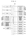
- the detailed configuration of the vehicle control device 100 will now be described with reference to FIG. 3 .
- FIG. 3 is a block diagram showing the electrical configuration of the vehicle control device 100.
- the vehicle control device 100 includes a CPU 71, a ROM 72, and a RAM 73, which are connected to an input/output port 75 via a bus line 74.
- a plurality of devices such as the wheel drive device 3 are connected to the input/output port 75.
- the CPU 71 is an arithmetic unit which controls the respective portions connected by the bus line 74.
- the ROM 72 is a non-rewritable nonvolatile memory storing a control program executed by the CPU 71, fixed value data, and the like.
- the RAM 73 is a memory for storing various rewritable data at the time of executing the control program. Note that, in the ROM 72, a program of a flowchart (camber control process) shown in FIG. 7 is stored.
- the wheel drive device 3 is a device for rotatably drives each wheel 2 (see FIG. 1 ), and mainly includes the four motors, i.e., the FL motor 3FL to the RR motor 3RR, which provide rotational driving force to the respective wheels 2 and a driving circuit (not shown) which performs drive control of the respective motors 3FL to 3RR based on a command from the CPU 71.
- the camber angle adjustment device 4 is a drive device for adjusting the steering angle and the camber angle of each wheel 2.
- the camber angle adjustment device 4 mainly includes the four actuators, i.e., the FL actuator 4FL to the RR actuator 4RR, which provide the driving force for angle adjustments of the respective wheels 2 (wheel drive devices 3), and a driving circuit (not shown) which performs drive control of the respective actuators 4FL to 4RR based on a command from the CPU 71.
- the FL actuator 4FL to the RR actuator 4RR mainly include the three hydraulic pressure cylinders 4a to 4c, a hydraulic pressure pump 4d (see FIG. 1 ) which supplies oil (hydraulic pressure) to the respective hydraulic pressure cylinders 4a to 4c, an electromagnetic valve (not shown) which switches the supply direction of the oil supplied from the hydraulic pressure pump to the respective hydraulic pressure cylinders 4a to 4c, and an extension/contraction sensor (not shown) which detects the extension/contraction amount of the respective hydraulic pressure cylinders 4a to 4c (rod portions).
- the driving circuit of the camber angle adjustment device 4 performs the drive control of the hydraulic pressure pump based on a command from the CPU 71, the respective hydraulic pressure cylinders 4a to 4c are driven to extend or contract by the oil (hydraulic pressure) supplied from the hydraulic pressure pump.
- the electromagnetic valve is turned on/off, the driving direction (extension or contraction) of the respective hydraulic pressure cylinders 4a to 4c is switched.
- the driving circuit of the camber angle adjustment device 4 monitors the extension/contraction amount of the respective hydraulic pressure cylinders 4a to 4c through the extension/contraction sensor, and the extension/contraction drive of the hydraulic pressure cylinders 4a to 4c which have reached a target value (extension/contraction amount) instructed by the CPU 71 is stopped. Note that the detection result by the extension/contraction sensor is output from the driving circuit to the CPU 71, and the CPU 71 can obtain the current steering angle and the camber angle of each wheel 2 based on the detection result.
- a vehicle speed sensor device 32 is a device for detecting a ground speed (absolute value and proceeding direction) of the vehicle 1 with respect to the road surface G and outputting the detection result to the CPU 71.
- the vehicle speed sensor device 32 mainly includes a longitudinal direction acceleration sensor 32a, a horizontal direction acceleration sensor 32b, and a control circuit (not shown) which processes the detection results of the respective acceleration sensors 32a and 32b and outputs them to the CPU 71.
- the longitudinal direction acceleration sensor 32a is a sensor which detects the acceleration of the vehicle 1 (body frame BF) in the longitudinal direction (vertical direction in FIG. 1 )
- the horizontal direction acceleration sensor 32b is a sensor which detects the acceleration of the vehicle 1 (body frame BF) in the horizontal direction (left-right direction in FIG. 1 ).
- the respective acceleration sensors 32a and 32b are configured as piezoelectric sensors using a piezoelectric element.
- the CPU 71 can time-integrate the detection results (acceleration values) of the respective acceleration sensors 32a and 32b input from the control circuit of the vehicle speed sensor device 32 to calculate the respective speeds in the two directions (longitudinal and horizontal directions), and obtain the ground speed (absolute value and proceeding direction) of the vehicle 1 by synthesizing the components in the two directions.
- a vertical load sensor device 34 is a device for detecting the load applied to the ground contact area of each wheel 2 from the road surface G and outputting the detection result to the CPU 71.
- the vertical load sensor device 34 includes an FL load sensor 34FL to an RR load sensor 34RR which respectively detect the loads applied to the respective wheels 2 and a processing circuit (not shown) which processes the detection results of the respective FL load sensor 34 FL to RR load sensor RR and outputs them to the CPU 71.
- the respective load sensors 34FL to 34RR are configured as piezoresistive three-shaft load sensors.
- the respective load sensors 34FL to 34RR are arranged on a suspension shaft (not shown) of the respective wheels 2, and detect the loads applied to the wheels 2 described above from the road surface G in three directions of the longitudinal direction (virtual axis Xf-Xb direction), the horizontal direction (virtual axis Yl-Yr direction), and the vertical direction (virtual axis Zu-Zd direction) of the vehicle 1 (see FIG 2B ).
- the CPU 71 estimates a friction coefficient ⁇ of the road surface G in the ground contact area of each wheel 2 in the following manner from the detection result (vertical load) of the each of the load sensors 34FL to 34RR input from the vertical load sensor device 34.
- the friction coefficient ⁇ can obviously be detected by other methods. Examples of other methods include known technology disclosed in Japanese Patent Application Publication No. JP-A-2001-315633 and Japanese Patent Application Publication No. JP-A-2003-118554 .
- a wheel rotation speed sensor device 35 is a device for detecting the rotational speed of each wheel 2 and outputting the detection result to the CPU 71.
- the wheel rotation speed sensor device 35 includes four rotation sensors, i.e., an FL rotation sensor speed 35FL to an RR rotation speed sensor 35RR, which respectively detect the rotational speeds of the respective wheels 2 and a processing circuit (not shown) which processes the detection results of the respective rotation speed sensors 35FL to 35RR and outputs them to the CPU 71.
- the respective rotation speed sensors 35FL to 35RR are provided on the respective wheels 2, and detect the angular speeds of the respective wheels 2 as the rotational speeds. That is, the respective rotation speed sensors 35FL to 35RR are configured as electromagnetic pickup sensors including a rotation body which rotates in conjunction with each wheel 2 and a pickup which electromagnetically detects the presence or absence of a lot of teeth formed in the circumference direction of the rotation body.
- the CPU 71 can obtain the actual circumference speed of each wheel 2 from the rotational speed of each wheel 2 input from the wheel rotation speed sensor device 35 and the outer diameter of each wheel 2 stored in the ROM 72 in advance, and can determine whether each wheel 2 is slipping by comparing the circumference speed thereof and the driving speed (ground speed) of the vehicle 1.
- An accelerator pedal sensor device 52a is a device for detecting the operation state of the accelerator pedal 52 and outputting the detection result thereof to the CPU 71.
- the accelerator pedal sensor device 52a mainly includes an angle sensor (not shown) which detects the depression state of the accelerator pedal 52 and a control circuit (not shown) which processes the detection result of the angle sensor and outputs it to the CPU 71.
- a brake pedal sensor device 53a is a device for detecting the operation state of the brake pedal 53 and outputting the detection result thereof to the CPU 71.
- the brake pedal sensor device 53a mainly includes an angle sensor (not shown) which detects the depression state of the brake pedal 53 and a control circuit which processes the detection result of the angle sensor and outputs it to the CPU 71.
- a steering wheel sensor device 54a is a device for detecting the operation state of the steering wheel 54 and outputting the detection result thereof to the CPU 71.
- the steering wheel sensor device 54a mainly includes an angle sensor (not shown) which detects the operation state of the steering wheel 54 and a control circuit (not shown) which processes the detection result of the angle sensor and outputs it to the CPU 71.
- a wiper switch sensor device 55a is a device for detecting the operation state of the wiper switch 55 and outputting the detection result thereof to the CPU 71.
- the wiper switch sensor device 55a mainly includes a positioning sensor (not shown) which detects the operation state (operation position) of the wiper switch 55 and a control circuit (not shown) which processes the detection result of the positioning sensor and outputs it to the CPU 71.
- a turn signal switch sensor device 56a is a device for detecting the operation state of the turn signal switch 56 and outputting the detection result thereof to the CPU 71.
- the turn signal switch sensor device 56a mainly includes a positioning sensor (not shown) which detects the operation state (operation position) of the turn signal switch 56 and a control circuit (not shown) which processes the detection result of the positioning sensor and outputs it to the CPU 71.
- a high grip switch sensor device 57a is a device for detecting the operation state of the high grip switch 57 and outputting the detection result thereof to the CPU 71.
- the high grip switch sensor device 57a mainly includes a positioning sensor (not shown) which detects the operation state (operation position) of the high grip switch 57 and a control circuit (not shown) which processes the detection result of the positioning sensor and outputs it to the CPU 71.
- the respective angle sensors are configured as contact-type potentiometers using electrical resistance.
- the CPU 71 can obtain the depression amount of each of the pedals 52 and 53 and the operation angle of the steering wheel 54 from the detection results input from the control circuits of the respective sensor devices 52a to 54a, and obtain the depression speed (operation speed) of each of the pedals 52 and 53 and the rotational speed (operation speed) of the steering wheel 54 by time-integrating the detection results.
- Examples of other input/output device 36 shown in FIG. 3 include a rainfall sensor which detects rainfall or an optical sensor which detects the state of the road surface G without contact.
- FIG. 4 is a schematic view showing the top view of the vehicle 1.
- FIGS. 5 and 6 are schematic views showing the front view of the vehicle 1.
- FIG. 5 shows a state where the wheel 2 is provided with a negative camber
- FIG. 6 shows a state where the wheel 2 is provided with a positive camber.
- the wheel 2 includes two types of treads, the first tread 21 and the second tread 22. As shown in FIG. 4 , in each of the wheels 2 (front wheels 2FL and 2FR, and rear wheels 2RL and 2RR), the first tread 21 is arranged on the inside of the vehicle 1, and the second tread 22 is arranged on the outside of the vehicle 1.
- the two treads 21 and 22 are configured to have the same width dimensions (dimensions in the horizontal direction in FIG. 4 ).
- the first tread 21 is configured to have a characteristic of a higher grip force (higher grip performance) compared to the second tread 22.
- the second tread 22 is configured to have a characteristic of a smaller rolling resistance (lower rolling resistance) compared to the first tread 21.
- a ground contact pressure Rin of the first tread 21 arranged on the inside of the vehicle 1 is increased and a ground contact pressure Rout of the second tread 22 arranged on the outside of the vehicle 1 is decreased. Accordingly, by leveraging the high grip performance of the first tread 21, the driving performance (for example, the turning performance, the acceleration performance, the brake performance, or vehicle stability in the rain) can be improved.
- FIG. 7 is a flowchart showing a camber control process. This process is a process executed repeatedly (for example, at intervals of 0.2 ms) by the CPU 71 while the power of the vehicle control device 100 is applied. Thus, the compatibility between two performances of the driving performance and the fuel saving performance described above is provided by adjusting the camber angle given to the wheel 2.
- the CPU 71 first determines whether the wiper switch 55 is turned on, i.e., whether a wiping operation of a wiper for a windshield is instructed by the driver (S1). In the case where it is determined that the wiper switch 55 is turned on as a result (S1: Yes), it is estimated that there is a possibility that the current weather is rainy and a water film is formed on the road surface G. Therefore, the negative camber is provided to the wheel 2 (S6) to terminate the camber process.
- the ground contact pressure Rin of the first tread 21 is increased and the ground contact pressure Rout of the second tread 22 is decreased (see FIG. 5 ). Therefore, the vehicle stability in the rain can be improved by leveraging the high grip performance of the first tread 21.
- the ground contact pressure Rin of the first tread 21 is increased and the ground contact pressure Rout of the second tread 22 is decreased (see FIG. 5 ). Therefore, a slip of the wheel 2 can be prevented by leveraging the high grip performance of the first tread 21. Thus, the acceleration performance of the vehicle 1 can be improved.
- the sudden acceleration is not instructed and it is estimated as moderate acceleration or constant-speed driving. Then, it is determined whether the depression amount of the brake pedal 53 is greater than or equal to a predetermined value, i.e., whether a brake of a predetermined level or greater (sudden brake) is instructed by the driver (S3).
- a predetermined value i.e., whether a brake of a predetermined level or greater (sudden brake) is instructed by the driver (S3).
- the ground contact pressure Rin of the first tread 21 is increased and the ground contact pressure Rout of the second tread 22 is decreased (see FIG. 5 ). Therefore, a lock of the wheel 2 can be prevented by leveraging the high grip performance of the first tread 21. Thus, the brake performance of the vehicle 1 can be improved.
- the sudden brake is not instructed and it is estimated as moderate brake or constant-speed driving. Then, it is determined whether the vehicle speed (ground speed) is less than or equal to a predetermined value (for example, 15 km per hour), i.e., whether it is a low-speed driving (S 17).
- a predetermined value for example, 15 km per hour
- the ground contact pressure Rin of the first tread 21 is increased and the ground contact pressure Rout of the second tread 22 is decreased (see FIG. 5 ). Therefore, a lock or a slip of the wheel 2 can be prevented by leveraging the high grip performance of the first tread 21 and thereby increasing the grip force of the wheel 2. As a result, the brake performance and the acceleration performance of the vehicle 1 can be improved.
- the stopping force of the vehicle 1 (wheel 2) can be ensured by leveraging the high grip performance of the first tread 21 after the vehicle 1 is stopped, the vehicle 1 can be stopped in a stable state. Further, in the case of restarting after the stop, the ground contact pressure Rin is increased in advance. Accordingly, the wheel 2 can be prevented from slipping, and the restart of the vehicle 1 can be performed smoothly and promptly.
- the vehicle speed is not low and it is estimated that the driving force or brake force at the time of acceleration or deceleration has a relatively small value. Then, it is determined whether the turn signal switch 56 is turned on, i.e., whether a right or left turn or a lane change is instructed by the driver (S 18).
- the ground contact pressure Rin of the first tread 21 is increased and the ground contact pressure Rout of the second tread 22 is decreased (see FIG. 5 ). Therefore, a slip of the wheel 2 can be prevented by leveraging the high grip performance of the first tread 21, and the turning performance of the vehicle 1 can be improved.
- the ground contact pressure Rin of the first tread 21 is increased and the ground contact pressure Rout of the second tread 22 is decreased (see FIG. 5 ). Therefore, a slip of the wheel 2 can be prevented by leveraging the high grip performance of the first tread 21. As a result, the brake performance, the acceleration performance, or the turning performance of the vehicle 1 can be improved.
- the ground contact pressure Rin of the first tread 21 is increased and the ground contact pressure Rout of the second tread 22 is decreased (see FIG. 5 ). Therefore, a slip of the wheel 2 (spin of the vehicle 1) can be prevented by leveraging the high grip performance of the first tread 21. As a result, the turning performance of the vehicle 1 can be improved.
- the ground contact pressure Rin of the first tread 21 is decreased and the ground contact pressure Rout of the second tread 22 is increased (see FIG. 6 ). Therefore, the rolling efficiency of the wheel 2 can be improved by leveraging the low rolling resistance of the second tread 22, and the fuel saving performance of the vehicle 1 can be improved.
- the compatibility can be provided between the two performances, i.e., the acceleration performance as well as the brake performance and the fuel saving performance which conflict with each other, by adjusting the camber angles ⁇ R and ⁇ L of the wheel 2 by the camber angle adjustment device 4 to change the ratio of the ground contact pressure Rin in the first tread 21 and the ground contact pressure Rout in the second tread 22.
- FIG. 8 is a top view of a wheel 202 of the second embodiment
- FIG. 9 is a schematic view showing a top view of a vehicle 201.
- FIG. 10 is a schematic view showing a front view of the vehicle 201 making a left turn in a state where the left and right wheels 202 are provided with steering angles for a left turn, the turning outer wheel (right front wheel 202FR) is provided with a negative camber, and the turning inner wheel (left wheel 202FL) is provided with a constant camber angle.
- the wheel 202 of the second embodiment is configured such that the outer diameter of a first tread 221 is gradually decreased. Note that the same portions as those of the first embodiment described above are denoted by the same reference numerals, and descriptions thereof will be omitted.
- the wheel 202 of the second embodiment includes the first tread 221 arranged on the inside of the vehicle 201 (right side in FIG. 8 ) and the second tread 22 having a different characteristic from the first tread 221 and arranged on the outside of the vehicle 201 (left side in FIG. 8 ).
- first tread 221 is configured to have a characteristic of a higher grip force (higher grip performance) compared to the second tread 22, and the second tread 22 is configured to have a characteristic of a smaller rolling resistance (lower rolling resistance) compared to the first tread 221.
- the wheel 202 is configured such that the width dimensions (dimensions in the horizontal direction in FIG. 8 ) of the two treads 221 and 22 are the same
- the second tread 22 is configured to have an outer diameter approximately constant in the width direction (horizontal direction in FIG. 8 ) while the first tread 221 is configured to have an outer diameter which gradually decreases from the second tread 22 side (left side in FIG. 8 ) toward the inside of the vehicle 201 (right side in FIG. 8 ).
- the second tread 22 can be caused to contact the ground in a state where the first tread 221 does not contact the road surface G even if a large camber angle is not provided (i.e., the camber angle is set to 0°) in the wheel 202 (left front wheel 202FL).
- the rolling resistance of the entire wheel 202 can be reduced to further improve the fuel saving performance.
- the first tread 221 does not contact the ground and the second tread 22 contacts the ground at a smaller camber angle, so that the wear of the two treads 221 and 22 can be suppressed to achieve a longer service life.
- the ground contact pressure on the first tread 221 can be made uniform in the entire region in the width direction (horizontal direction in FIG. 8 ) because the outer diameter of the first tread 221 is gradually decreased. Thus, a concentration of the ground contact pressure on a tread end portion can be suppressed.
- the driving performance (such as the turning performance, the acceleration performance, the brake performance, and driving stability in the rain) can further be improved, and a biased wear of the first tread 221 can be suppressed to achieve a longer service life.
- FIG. 11 is a flowchart showing the camber control process.
- the negative cambers (camber angles at which at least the second tread 22 is made distant from the road surface G in this embodiment, see the right front wheel 202FR shown in FIG. 10 ) are provided to the left and right wheels 202 (S27) to terminate the camber process.
- the ground contact pressure Rin of the first tread 221 is increased and the ground contact pressure Rout of the second tread 22 is decreased (the ground contact pressure Rout becomes zero in this embodiment). Therefore, a slip or lock of the wheel 202 can be prevented by leveraging the high grip performance of the first tread 221, and driving stability and the acceleration/brake performance of the vehicle 201 can be improved.
- camber angles ⁇ R and ⁇ L provided to the left and right wheels 202 are preferably the same angle during the straight-ahead driving.
- the camber angles ⁇ R and ⁇ L are preferably angles larger than that at which the second tread 22 is made distant from the road surface G.
- the constant camber angle is given to the wheel 202 (S25) to terminate the camber process.
- the constant camber angle is set to 0° (see the left front wheel 202FL shown in FIG. 10 ).
- the second tread 22 can be caused to contact the ground in the state where the first tread 221 does not contact the road surface G. Therefore, the rolling resistance of the entire wheel 202 can be reduced to further improve the fuel saving performance.
- the first tread 221 does not contact the ground and the second tread 22 contacts the ground at the camber angle of 0°, whereby the wear of the two treads 221 and 22 can be suppressed to achieve a longer service life.
- the tight turn is instructed by the driver. Accordingly, the wheel 202 may slip to spin the vehicle 201.
- the negative camber is provided to the turning outer wheel (right front wheel 202FR in FIG. 10 ) and the constant camber angle is provided (S26) to the turning inner wheel (left front wheel 202FL in FIG. 10 ) to terminate the camber process.
- the cost for the control drive can be reduced while ensuring the turning performance. That is, because the ground contact pressure Rin of the first tread 221 is increased and the ground contact pressure Rout of the second tread 22 is reduced (to zero in this embodiment) in the turning outer wheel (see FIG. 10 ), a slip of the wheel 202 (spin of the vehicle 201) can be prevented by leveraging the high grip performance of the first tread 221, and the turning performance of the vehicle 201 can be improved.
- the cost of the control by the vehicle control device 100 or the cost of the drive by the camber angle adjustment device 4 can be reduced.
- FIG. 12 is a top view of a wheel 302 of the third embodiment.
- FIG. 13 is a schematic view showing a front view of a vehicle 301 making a left turn.
- a turning outer wheel (right front wheel 302FR) is provided with the negative camber
- a turning inner wheel (left wheel 302FL) is provided with the positive camber.
- the wheel 302 of the third embodiment is configured such that the outer diameter of a first tread 221 and the outer diameter of a third tread 323 are gradually decreased. Note that the same portions as those of the respective embodiments described above are denoted by the same reference numerals, and descriptions thereof will be omitted.
- the wheel 302 of the third embodiment includes the third tread 323, and the first tread 221 is arranged on the inside of the vehicle 301 (right side in FIG. 12 ), the third tread 323 is arranged on the outside of the vehicle 301 (left side in FIG. 12 ), and the second tread 22 is arranged between the first tread 221 and the third tread 323.
- the third tread 323 is configured to have a characteristic of a higher grip force at least compared to the second tread 22, and the third tread 323 is configured such that the diameter gradually decreases from the second tread 22 side (right side in FIG. 12 ) toward the outside of the vehicle 301 (left side in FIG. 12 ), as shown in FIG. 12 .
- the second tread 22 can be caused to contact the ground in a state where the first tread 221 and the third tread 323 are apart from the road surface G without providing a large camber angle to the wheel 302 (for example, even if the camber angle is set to 0°). Accordingly, the rolling resistance of the entire wheel 302 can be reduced to further improve the fuel saving performance.
- the wear of the respective treads 221, 22, and 323 can be suppressed to achieve a longer service life.
- the ground contact pressure on the third tread 323 can be made uniform in the entire region in the width direction (horizontal direction in FIG. 12 ) since the outer diameter of the third tread 323 is gradually decreased. Thus, concentration of the ground contact pressure on a tread end portion can be suppressed.
- the driving performance (such as the turning performance, the acceleration performance, the brake performance, and driving stability in the rain) can further be improved, and the biased wear can be suppressed to achieve a longer service life.
- FIG. 14 is a flowchart showing the camber control process.
- the constant camber angle is provided to the wheel 302 (S25) to terminate the camber process. Note that, in this embodiment, the constant camber angle is set to 0° (see the left front wheel 202FL shown in FIG. 10 ).
- the second tread 22 can be caused to contact the ground in the state where the first tread 221 and the third tread 323 are apart from the road surface G, whereby the rolling resistance of the entire wheel 302 can be reduced to further improve the fuel saving performance.
- the first tread 221 and the third tread 323 do not contact the ground and the second tread 22 contacts the ground at the camber angle of 0°, whereby the wear of the respective treads 221, 22, and 323 can be suppressed to achieve a longer service life.
- the tight turn is instructed by the driver. Accordingly, the wheel 302 may slip to spin the vehicle 301.
- the negative camber is provided to the turning outer wheel (right front wheel 302FR in FIG. 13 ) and the positive camber is provided (S36) to the turning inner wheel (left front wheel 302FL in FIG. 13 ) to terminate the camber process.
- FIG. 15 is a flowchart showing the camber control process of the fourth embodiment.
- the fourth embodiment is configured such that the camber angle of the wheel 202 is adjusted in the case where any of the wheels 202 are slipping.
- the CPU 71 first detects the vehicle speed (S41), detects the rotational speed (circumferential speed) of the wheel 202 (S42), and determines whether any of the wheel 202 are slipping (S43) based on the vehicle speed and the circumferential speed of the wheel 202. Note that the vehicle speed and the circumferential speed of the wheel 202 is calculated by the vehicle speed sensor device 32 and the wheel rotation speed sensor device 35 as described above.
- the second tread 22 can be caused to contact the ground in the state where the first tread 221 does not contact the road surface G. Accordingly, the rolling resistance of the entire wheel 202 can be reduced to further improve the fuel saving performance.
- the first tread 221 does not contact the ground and the second tread 22 contacts the ground at the camber angle of 0°, whereby the wear of the two treads 221 and 22 can be suppressed to achieve a longer service life.
- the ground contact pressure Rin of the first tread 221 is increased and the ground contact pressure Rout of the second tread 22 is decreased (the ground contact pressure Rout becomes zero in this embodiment). Therefore, a slip of the wheel 202 can be prevented by leveraging the high grip performance of the first tread 221, and the acceleration performance and the driving stability of the vehicle 201 can be improved.
- the processes of S5 and S6 correspond to an activation control unit according to a first aspect of the present invention
- the process of S17 corresponds to a ground speed determination unit and the process of S6 corresponds to a low-speed-time activation control unit according to a second aspect of the present invention
- the processes of S1, S2, S3, S18, S19, and S4 correspond to an operation state determination unit and the process of S6 corresponds to an operation-time activation control unit according to a third aspect of the present invention, respectively.
- the processes of S25, S26, and S27 correspond to the activation control unit according to the first aspect
- the process of S 17 corresponds to the ground speed determination unit and the process of S27 corresponds to the low-speed-time activation control unit according to the second aspect
- the processes of S1, S2, S3, S18, S19, and S4 correspond to the operation state determination unit and the processes of S27 and S26 correspond to the operation-time activation control unit according to the third aspect, respectively.
- the processes of S25, S27, and S36 correspond to the activation control unit according to the first aspect
- the process of S 17 corresponds to the ground speed determination unit and the process of S27 corresponds to the low-speed-time activation control unit according to the second aspect
- the processes of S1, S2, S3, S18, S19, and S4 correspond to the operation state determination unit and the processes of S27 and S36 correspond to the operation-time activation control unit according to the third aspect, respectively.
- the operation speed of the accelerator pedal 52 and the brake pedal 53 can be given.
- the depression amount of the accelerator pedal 52 or the brake pedal 53 it may be configured such that the negative camber (positive camber) is provided if the operation speed is faster (slower) than a reference value.
- a gear shift operation of a transmission can be given.
- it may be configured such that, in the case where a gear shift operation (shift down operation) of increasing the deceleration of the transmission is performed, it is determined that a relatively large acceleration/deceleration is caused by the gear shift operation, whereby the negative camber is provided to the wheel. Accordingly, a slip or a lock of the wheel can be suppressed to improve the acceleration performance and the brake performance of the vehicle.
- the operation speed of the steering wheel 54 can be given.
- the operation angle of the steering wheel 54 it may be configured such that the negative camber (positive camber) is provided in the case where the operation speed is faster (slower) than a reference value.
- the process of making a determination based on the operation state of each of the pedals 52 and 53 has been described as an example of the operation state determination unit according to the third aspect.
- the vehicle speed sensor device 32 the longitudinal direction acceleration sensor 32a and the horizontal direction acceleration sensor 32b
- it may be configured such that the negative camber is provided to the wheel in the case where the acceleration/deceleration of the vehicle is greater than or equal to a predetermined value, and the positive camber is provided in the case where the predetermined value is not reached.
- it may be determined based on the acceleration/deceleration in two directions of the longitudinal direction of the vehicle and the horizontal direction of the vehicle, or may be determined based on the acceleration/deceleration in only one of the two directions.
- the process of making a determination based on the operation state of the wiper switch 55 has been described as an example of a road surface determination unit according to a fifth aspect of the present invention.
- it is not limited thereto, and it may be configured such that the negative camber is provided to the wheel in the case where the amount of precipitation is detected by the rainfall sensor and a detected value thereof is greater than or equal to a predetermined value, for example.
- the state of the road surface is detected by a non-contact optical sensor or the like, and the negative camber or the positive camber is provided to the wheel based on the detection result (such as state of water film on the road surface, snow accumulation state of the road surface, frozen state of the road surface, or pavement state) thereof.
- the order of determination on whether to provide the negative camber is in the order of the state of the wiper switch 55, the state of the accelerator pedal 52, the state of the brake pedal 53, the state of the vehicle speed, the state of the turn signal switch 56, the state of the high grip switch 57, and the state of the steering wheel 54 (see S1 to S4).
- the order is not limited thereto, and it may obviously be shuffled to obtain another order. Also, a part of the determination steps may obviously be omitted.
- camber angles ⁇ R and ⁇ L differing from each other ⁇ R ⁇ ⁇ L or ⁇ L ⁇ ⁇ R may obviously be provided to the left and right wheels.
- first tread 21 or 221 is arranged on the inside of the vehicle and the second tread 22 is arranged on the outside of the vehicle has been described.
- the positional relation is not limited thereto, and may obviously be changed appropriately for each wheel.
- the arrangement may be such that the first tread 21 or 221 is on the outside of the vehicle and the second tread 22 is on the inside of the vehicle, and the arrangement may be such that the first tread 21 or 221 is on the outside of the vehicle in the front wheel and the second tread 22 is on the inside of the vehicle in the rear wheel.
- the positional relation may differ for each wheel.
- the wheel has two types of treads and the case where the wheel has three types of treads have been described, but the wheels may obviously be combined.
- the wheel 2 or 202 having two types of treads is used for the front wheel and the wheel 302 having three types of treads is used for the rear wheel, or vice versa.
- first or third tread 21, 221, or 323 has the characteristic of a higher grip performance compared to the second tread 22, and the second tread 22 has the characteristic of a lower rolling resistance compared to the first or third tread 21, 221, or 323 has been described.
- the respective treads 21, 221, 22, and 323 may obviously be configured to have other characteristics.
- two types of tread patterns may be provided such that one tread has a characteristic of a high drainage and the other tread has a characteristic of small road noise.
- the friction coefficient ⁇ of the road surface on which the wheel 2 is driven can be given.
- the friction coefficient ⁇ can be estimated by the vertical load sensor device 34 as described above.
- the camber angle of the wheel 2 may be controlled based on whether the wheel 2 is locked (provided with the negative camber when locked).
- a vehicle control device 1 of a modified example is, in the vehicle control device according to the first aspect of the present invention, the activation control unit includes an acceleration/deceleration determination unit which determines an acceleration/deceleration state of the vehicle, and an acceleration/deceleration-time activation control unit which activates the camber angle adjustment device to adjust the camber angle of the wheel such that the ground contact pressure on the first tread becomes larger than the ground contact pressure on the second tread in the case where the acceleration/deceleration determination unit determines that the acceleration/deceleration state of the vehicle is of a predetermined amount or greater.
- acceleration/deceleration-time activation control unit may activate the camber angle adjustment device to adjust the camber angle of the wheel such that the ground contact pressure on the first tread is at least increased in the case where the acceleration/deceleration determination unit determines that the acceleration/deceleration state of the vehicle is of the predetermined value or greater.
- the ground contact pressure on the first tread can be made larger than the ground contact pressure on the second tread by the acceleration/deceleration-time activation control unit activating the camber angle adjustment device to adjust the camber angle of the wheel. Accordingly, there is an effect that the acceleration performance and the brake performance can be improved by using the first tread having the high grip performance.
- the ground contact pressure on the second tread can be made larger than the ground contact pressure on the first tread (i.e., the ground contact pressure on the first tread can be reduced) by activating the camber angle adjustment device to adjust the camber angle of the wheel. Accordingly, there is an effect that the fuel saving driving can be realized by using the second tread having the low rolling resistance.
- the activation control unit acceleration/deceleration-time activation control unit
- the camber angle of the wheel to change the ratio of the ground contact pressure on the first tread and the ground contact pressure on the second tread (including the state where only one tread contacts the ground and the other tread does not contact the road surface).
- the case where the acceleration/deceleration determination unit determines (does not determine) that the acceleration/deceleration state of the vehicle is of the predetermined amount or greater refers, for example, not only to a case where the actual acceleration/deceleration state of the vehicle measured by an acceleration sensor has already become (has not become) that of the predetermined amount or greater, but also to a case where the acceleration/deceleration state of the vehicle is expected to be that of the predetermined amount or greater (not to be that of the predetermined amount or greater) based on the operation member (for example, the operation state of the accelerator pedal or the brake pedal) operated by the driver.
- the operation member for example, the operation state of the accelerator pedal or the brake pedal
- a vehicle control device 2 of another modified example of the present invention is, in the vehicle control device according to the first aspect or the vehicle control device 1, the activation control unit includes a turn determination unit which determines a turning state of the vehicle, and a turning-time activation control unit which activates the camber angle adjustment device to adjust the camber angle of the wheel such that the ground contact pressure on the first tread becomes larger than the ground contact pressure on the second tread in the case where the turn determination unit determines that the turning state of the vehicle is of a predetermined amount or greater.
- the turning-time activation control unit may activate the camber angle adjustment device to adjust the camber angle of the wheel such that the ground contact pressure on the first tread is at least increased in the case where the turn determination unit determines that the turning state of the vehicle is of the predetermined amount or greater.
- the ground contact pressure on the first tread can be made larger than the ground contact pressure on the second tread by the turning-time activation control unit activating the camber angle adjustment device to adjust the camber angle of the wheel. Accordingly, there is an effect that the turning performance can be improved by using the first tread having the high grip performance.
- the ground contact pressure on the second tread can be made larger than the ground contact pressure on the first tread (i.e., the ground contact pressure on the first tread can be reduced) by activating the camber angle adjustment device to adjust the camber angle of the wheel. Accordingly, there is an effect that the fuel saving driving can be realized using the second tread having the low rolling resistance.
- the activation control unit turning-time activation control unit
- the camber angle of the wheel to change the ratio of the ground contact pressure on the first tread and the ground contact pressure on the second tread (including the state where only one tread contacts the ground and the other tread does not contact the road surface).
- the case where the turn determination unit determines (does not determine) that the turning state of the vehicle is of the predetermined amount or greater refers not only to a case where the actual turning state of the vehicle has already become (has not become) that of the predetermined amount or greater, but also to a case where the turning state of the vehicle is expected to be that of the predetermined amount or greater (not to be that of the predetermined amount or greater) based on the operation member (for example, the operation state of the steering wheel) operated by the driver.
- a vehicle control device 3 of still another modified example of the present invention is, in the vehicle control device according to the first aspect or the vehicle control device 1 or 2, the activation control unit includes a road surface determination unit which determines the state of the road surface on which the wheel is driven, and a road surface change-time activation control unit which activates the camber angle adjustment device to adjust the camber angle of the wheel such that the ground contact pressure on the first tread becomes larger than the ground contact pressure on the second tread in the case where the road surface determination unit determines that the state of the road surface on which the wheel is driven is in a state satisfying a predetermined condition.
- the activation control unit includes a road surface determination unit which determines the state of the road surface on which the wheel is driven, and a road surface change-time activation control unit which activates the camber angle adjustment device to adjust the camber angle of the wheel such that the ground contact pressure on the first tread becomes larger than the ground contact pressure on the second tread in the case where the road surface determination unit determines that the state of the road surface on which the wheel is driven
- the road surface change-time activation control unit may activate the camber angle adjustment device to adjust the camber angle of the wheel such that the ground contact pressure on the first tread is at least increased in the case where the road surface determination unit determines that the state of the road surface on which the wheel is driven is in the state satisfying the predetermined condition.
- the ground contact pressure on the first tread can be made larger than the ground contact pressure on the second tread by the road surface change-time activation control unit activating the camber angle adjustment device to adjust the camber angle of the wheel. Accordingly, there is an effect that the driving performance (for example, driving stability in the rain, on snow road, on icy road, or when driving on unpaved road) can be improved by using the first tread having the high grip performance.
- the ground contact pressure on the second tread can be made larger than the ground contact pressure on the first tread (i.e., the ground contact pressure on the first tread can be reduced) by activating the camber angle adjustment device to adjust the camber angle of the wheel. Accordingly, there is an effect that the fuel saving driving can be realized using the second tread having the low rolling resistance.
- the activation control unit road surface change-time activation control unit
- the camber angle of the wheel to change the ratio of the ground contact pressure on the first tread and the ground contact pressure on the second tread (including the state where only one tread contacts the ground and the other tread does not contact the road surface).
- the case where the road surface determination unit determines (does not determine) that the state of the road surface on which the wheel is driven is in the state satisfying the predetermined condition refers not only to a case where the state of the road surface has already become (has not become) the state satisfying the predetermined condition, but also to a case where the state of the road surface is expected to become the state satisfying the predetermined condition (not become the state satisfying the predetermined condition) based on the operation member (for example, the operation state of a wiper operation lever) operated by the driver.
- the operation member for example, the operation state of a wiper operation lever
- a vehicle control device 4 of still another modified example of the present invention is, in the vehicle control device according to the first aspect or any one of the vehicle control devices 1 to 3, the wheel is configured such that the outer diameter in the second tread is approximately constant in the width direction of the wheel and is configured such that the outer diameter in the first tread is gradually decreased from the second tread side toward the inside or outside of the vehicle.
- the second tread is configured such that the outer diameter is approximately constant in the width direction of the wheel and the first tread is configured such that the outer diameter is gradually decreased from the second tread side toward the inside or outside of the vehicle. Therefore, only the second tread can be caused to contact the ground in a state where the first tread does not contact the road surface, even if a large camber angle is not provided to the wheel (for example, even if the camber angle is set to 0°).
- the rolling resistance of the entire wheel can be reduced to further improve the fuel saving performance.
- the first tread not contacting the ground and the second tread contacting the ground at a smaller camber angle there is an effect that the wear of the two treads can respectively be suppressed to achieve a longer service life.
- the ground contact pressure on the first tread can be made uniform in the entire region in the width direction such that the ground contact pressure is not concentrated in a tread end portion since the outer diameter of the first tread is gradually decreased, whereby there is an effect that the driving performance (the turning performance, the acceleration performance, the brake performance, the driving stability in the rain, and the like) can further be improved by efficiently using the first tread having the high grip performance and the biased wear can be suppressed to achieve a longer service life.
- the driving performance the turning performance, the acceleration performance, the brake performance, the driving stability in the rain, and the like
- a vehicle control device 5 of yet another modified example of the present invention is, in the vehicle control device 4, the wheel includes a third tread configured to have a characteristic of a higher grip performance at least compared to the second tread, the first tread being arranged on the inside of the vehicle, the third tread being arranged on the outside of the vehicle, the second tread being arranged between the first tread and the third tread, and the third tread being configured to have an outer diameter gradually decreasing from the second tread side toward the outside of the vehicle.
- the third tread is configured such that the outer diameter is gradually decreased from the second tread side toward the outside of the vehicle, only the second tread can be caused to contact the ground in a state where the first tread and the third tread are apart from the road surface, even if a large camber angle is not provided to the wheel (for example, even if the camber angle is set to 0°) also in the case where the third tread is further provided in addition to the first and second treads.
- the rolling resistance of the entire wheel can be reduced to further improve the fuel saving performance.
- the first tread and the third tread not contacting the ground and the second tread contacting the ground at a smaller camber angle, there is an effect that the wear of the respective treads can be suppressed to achieve a longer service life.
- the ground contact pressure on the third tread can be made uniform in the entire region in the width direction such that the ground contact pressure is not concentrated in a tread end portion since the outer diameter of the third tread is gradually decreased. Accordingly, there is an effect that the driving performance (the turning performance, the acceleration performance, the brake performance, the driving stability in the rain, and the like) can further be improved by efficiently using the third tread having the high grip performance and the biased wear can be suppressed to achieve a longer service life.
- a vehicle control device 6 of still another modified example of the present invention is, in the vehicle control device 5, the wheel is arranged on the left and the right of the vehicle, and the activation control unit includes a first turning activation control unit which activates the camber angle adjustment device to adjust the camber angle such that both of the left and right wheels are inclined to the inward side of the turn in the case where the vehicle is turned, thereby causing the ground contact pressure on the first tread to be larger than the ground contact pressures in the second and third treads in the turning outer wheel and the ground contact pressure on the third tread to be larger than the ground contact pressures in the first and second treads in the turning inner wheel.
- the first turning activation control unit may activate the camber angle adjustment device such that the ground contact pressure on the first tread is at least increased in the turning outer wheel and the ground contact pressure on the third tread is at least decreased in the turning inner wheel.
- the wheel having the first to third treads is arranged on the left and the right of the vehicle, and the first turning activation control unit adjusts the camber angle such that both of the left and right wheels are inclined to the inward side of the turn (i.e., such that turning outer wheel is provided with the negative camber and the turning inner wheel is provided with the positive camber) in the case where the vehicle is turned. Therefore, lateral forces can be applied to the respective left and right wheels to use the lateral forces of the two wheels as the turning force, whereby there is an effect that the turning performance can further be improved.
- a vehicle control device 7 of further another modified example of the present invention is, in the vehicle control device according to the first aspect or any one of the vehicle control devices 1 to 4, the wheel is arranged on the left and the right of the vehicle, and the activation control unit includes a second turning activation control unit which activates the camber angle adjustment device to adjust the camber angle of the turning outer wheel of the left and right wheels in the case where the vehicle is turned, thereby causing the ground contact pressure on the first tread in the turning outer wheel to be larger than the ground contact pressure on the second tread in the turning outer wheel.
- the second turning activation control unit may activate the camber angle adjustment device to adjust the camber angle of the turning outer wheel of the left and right wheels such that the ground contact pressure on the first tread in the turning outer wheel is at least increased.
- the wheel having the first and second treads is arranged on the left and the right of the vehicle, and the second turning activation control unit adjusts the camber angle of the turning outer wheel of the left and right wheels (for example, causes only the turning outer wheel to be inclined to the inward side of the turn, i.e., the negative camber side, such that the turning inner wheel maintains the same camber angle as that in the straight-ahead driving) in the case where the vehicle is turned. Therefore, there is an effect that the cost of the control drive can be reduced while ensuring the turning performance.
- the turning performance can be ensured using the first tread having the high grip performance by causing the ground contact pressure on the first tread to be larger than the ground contact pressure on the second tread in the turning outer wheel.
- the adjustment of the camber angle is made unnecessary (i.e., maintaining the camber angle of the straight-ahead driving), whereby the cost of the control of the vehicle control device or the cost of driving the camber angle adjustment device can be reduced.
- a vehicle control device 8 of still another modified example of the present invention is the vehicle control device according to the first aspect or any one of the vehicle control devices 1 to 7 including a ground speed detection unit which detects the ground speed of the vehicle, a rotational speed detection unit which detects the rotational speed of the wheel, and a slip determination unit which determines whether the wheel is slipping based on the ground speed and the rotational speed detected by the ground speed detection unit and the rotational speed detection unit, respectively.
- the activation control unit includes a slipping-time activation control unit which activates the camber angle adjustment device to adjust the camber angle of the wheel in the case where the slip determination unit determines that the wheel is slipping, thereby causing the ground contact pressure on the first tread or the third tread to be larger than the ground contact pressure on the second tread.
- the slipping-time activation control unit may activate the camber angle adjustment device to adjust the camber angle of the wheel such that the ground contact pressure on the first tread or the third tread is at least increased in the case where the slip determination unit determines that the wheel is slipping.
- the slip determination unit can adjust the camber angle of the slipping wheel to increase the ground contact pressure on the first tread or the third tread in the case where the slip determination unit determines that the wheel is slipping. Accordingly, there is an effect that the grip force can be recovered to improve the driving stability of the vehicle.
- the processes of S2 and S3 correspond to the acceleration/deceleration determination unit and the process of S6 corresponds to the acceleration/deceleration-time activation control unit of the vehicle control device 1
- the process of S4 corresponds to the turn determination unit and the process of S6 corresponds to the turning-time activation control unit of the vehicle control device 2
- the process of S 1 corresponds to the road surface determination unit and the process of S6 corresponds to the road surface change-time activation control unit of the vehicle control device 3, respectively.
- the processes of S2 and S3 correspond to the acceleration/deceleration determination unit and the process of S27 corresponds to the acceleration/deceleration-time activation control unit of the vehicle control device 1
- the process of S4 corresponds to the turn determination unit and the process of S26 corresponds to the turning-time activation control unit of the vehicle control device 2
- the process of S 1 corresponds to the road surface determination unit and the process of S27 corresponds to the road surface change-time activation control unit of the vehicle control device 3
- the process of S26 corresponds to the second turning activation control unit of the vehicle control device 7, respectively.
- the processes of S2 and S3 correspond to the acceleration/deceleration determination unit and the process of S27 corresponds to the acceleration/deceleration-time activation control unit of the vehicle control device 1
- the process of S4 corresponds to the turn determination unit and the process of S36 corresponds to the turning-time activation control unit of the vehicle control device 2
- the process of S 1 corresponds to the road surface determination unit and the process of S27 corresponds to the road surface change-time activation control unit of the vehicle control device 3
- the process of S36 corresponds to the first turning activation control unit of the vehicle control device 6, respectively.
- the process of S41 corresponds to the ground speed detection unit
- the process of S42 corresponds to the rotational speed detection unit
- the process of S43 corresponds to the slip determination unit
- the process of S45 corresponds to the slipping-time activation control unit of the vehicle control device 8, respectively.
Landscapes
- Engineering & Computer Science (AREA)
- Mechanical Engineering (AREA)
- Vehicle Body Suspensions (AREA)
- Steering-Linkage Mechanisms And Four-Wheel Steering (AREA)
- Tires In General (AREA)
Claims (2)
- Fahrzeugsteuervorrichtung (100), die eine Sturzwinkeleinstellvorrichtung (4) aktiviert, die einen Sturzwinkel eines Rads (2, 202, 302) einstellt, um den Sturzwinkel des Rads für ein Fahrzeug (1, 201, 301), welches das Rad und die Sturzwinkeleinstellvorrichtung (4) aufweist, zu steuern, wobei die Fahrzeugsteuervorrichtung (100) Folgendes aufweist:eine Aktivierungssteuereinheit, die einen Aktivierungszustand der Sturzwinkeleinstellvorrichtung (4) steuert, wobeidas Rad zumindest eine erste Lauffläche (21, 221) und eine zweite Lauffläche (22), die eine von der ersten Lauffläche (21, 221) verschiedene Charakteristik hat, aufweist, wobei die erste Lauffläche (21, 221) in einer Richtung der Breite des Rads an einer Innenseite oder einer Außenseite des Fahrzeugs (1, 201, 301) mit Bezug auf die zweite Lauffläche (22) angeordnet ist,die erste Lauffläche (21, 221) so konfiguriert ist, dass sie verglichen mit der zweiten Lauffläche (22) eine Charakteristik einer höheren Greifkraft hat, und die zweite Lauffläche (22) so konfiguriert ist, dass sie verglichen mit der ersten Lauffläche (21, 221) eine Charakteristik eines kleineren Rollwiderstands hat,die Aktivierungssteuereinheit ein Verhältnis aus einem Bodenkontaktdruck an der ersten Lauffläche (21, 221) und einem Bodenkontaktdruck an der zweiten Lauffläche (22) des Rads ändert, indem der Aktivierungszustand der Sturzwinkeleinstellvorrichtung (4) so gesteuert wird, dass der Sturzwinkel des Rads eingestellt wird, unddie Aktivierungssteuereinheit eine Betätigungszustandsbestimmungseinheit aufweist, die einen Betätigungszustand eines von einem Fahrer betätigten Betätigungselements (57) bestimmt, dadurch gekennzeichnet, dassdie Aktivierungssteuereinheit ferner eine Betätigungszeitaktivierungssteuereinheit aufweist, die den Sturzwinkel des Rads durch Aktivieren der Sturzwinkeleinstellvorrichtung (4) einstellt, um den Bodenkontaktdruck an der ersten Lauffläche (21, 221) zu erhöhen und den Kontaktdruck an der zweiten Lauffläche (22) zu verringern, falls die Betätigungszustandsbestimmungseinheit bestimmt, dass der Betätigungszustand des Betätigungselements (57) eine vorbestimmte Bedingung erfüllt, und die den Sturzwinkel des Rads durch Aktivieren der Sturzwinkeleinstellungsvorrichtung so einstellt, dass der Bodenkontaktdruck an der zweiten Lauffläche (22) erhöht wird und der Bodenkontaktdruck an der ersten Lauffläche (21, 221) verringert wird, falls die Betätigungszustandsbestimmungseinheit bestimmt, dass der Betätigungszustand des Betätigungselements (57) eine vorbestimmte Bedingung nicht erfüllt.
- Fahrzeugsteuervorrichtung (100) gemäß Anspruch 1, wobei
die Aktivierungssteuereinheit Folgendes aufweist:eine Bodengeschwindigkeitsbestimmungseinheit, die eine Bodengeschwindigkeit des Fahrzeugs (1, 201, 301) bestimmt; undeine Niedriggeschwindigkeitszeitaktivierungssteuereinheit, die den Sturzwinkel des Rads durch Aktivieren der Sturzwinkeleinstellvorrichtung (4) so einstellt, dass der Bodenkontaktdruck an der ersten Lauffläche (21, 221) zumindest erhöht wird, falls die Bodengeschwindigkeitsbestimmungseinheit bestimmt, dass die Bodengeschwindigkeit des Fahrzeugs (1, 201, 301) niedriger als oder gleich wie eine vorbestimmte Geschwindigkeit ist.
Applications Claiming Priority (3)
| Application Number | Priority Date | Filing Date | Title |
|---|---|---|---|
| JP2006182533 | 2006-06-30 | ||
| JP2006325027A JP4569560B2 (ja) | 2006-06-30 | 2006-11-30 | 車両用制御装置 |
| PCT/JP2007/063173 WO2008001913A1 (en) | 2006-06-30 | 2007-06-29 | Control device for vehicle |
Publications (3)
| Publication Number | Publication Date |
|---|---|
| EP2036745A1 EP2036745A1 (de) | 2009-03-18 |
| EP2036745A4 EP2036745A4 (de) | 2010-11-17 |
| EP2036745B1 true EP2036745B1 (de) | 2013-12-25 |
Family
ID=38845673
Family Applications (1)
| Application Number | Title | Priority Date | Filing Date |
|---|---|---|---|
| EP07767954.6A Expired - Fee Related EP2036745B1 (de) | 2006-06-30 | 2007-06-29 | Steuervorrichtung für fahrzeuge |
Country Status (4)
| Country | Link |
|---|---|
| US (1) | US8014919B2 (de) |
| EP (1) | EP2036745B1 (de) |
| JP (1) | JP4569560B2 (de) |
| WO (1) | WO2008001913A1 (de) |
Families Citing this family (34)
| Publication number | Priority date | Publication date | Assignee | Title |
|---|---|---|---|---|
| JP4998251B2 (ja) * | 2007-12-25 | 2012-08-15 | 株式会社エクォス・リサーチ | 車両 |
| CN101959702B (zh) * | 2008-02-04 | 2013-06-05 | 株式会社普利司通 | 无钉防滑轮胎 |
| EP2241462A4 (de) * | 2008-02-07 | 2012-10-03 | Equos Res Co Ltd | Steuerung und fahrzeug |
| JP5110290B2 (ja) * | 2008-03-25 | 2012-12-26 | 株式会社エクォス・リサーチ | 車両用制御装置 |
| JP2009184540A (ja) * | 2008-02-07 | 2009-08-20 | Equos Research Co Ltd | 制御装置及び車両 |
| JP5092778B2 (ja) * | 2008-02-08 | 2012-12-05 | 株式会社エクォス・リサーチ | 車両 |
| JP5446130B2 (ja) * | 2008-03-10 | 2014-03-19 | 株式会社エクォス・リサーチ | タイヤ |
| JP2009227009A (ja) * | 2008-03-20 | 2009-10-08 | Equos Research Co Ltd | 車両 |
| JP5141890B2 (ja) * | 2008-03-25 | 2013-02-13 | 株式会社エクォス・リサーチ | キャンバー角調整装置 |
| JP4952949B2 (ja) * | 2008-03-25 | 2012-06-13 | 株式会社エクォス・リサーチ | トウ・キャンバー角調整装置 |
| JP4946949B2 (ja) * | 2008-03-31 | 2012-06-06 | 株式会社エクォス・リサーチ | サスペンションシステム |
| JP2009241846A (ja) * | 2008-03-31 | 2009-10-22 | Equos Research Co Ltd | サスペンションシステム |
| JP5133137B2 (ja) * | 2008-05-29 | 2013-01-30 | 富士通テン株式会社 | 運転評価装置および運転評価方法 |
| JP5316316B2 (ja) * | 2009-02-26 | 2013-10-16 | 株式会社エクォス・リサーチ | 車両用制御装置 |
| JP2010228470A (ja) * | 2009-03-25 | 2010-10-14 | Equos Research Co Ltd | 車両用制御装置 |
| JP2010228474A (ja) * | 2009-03-25 | 2010-10-14 | Equos Research Co Ltd | 車両用制御装置 |
| JP2010235047A (ja) * | 2009-03-31 | 2010-10-21 | Equos Research Co Ltd | 車両用制御装置 |
| JP2010235016A (ja) * | 2009-03-31 | 2010-10-21 | Equos Research Co Ltd | 車両用制御装置 |
| JP5110055B2 (ja) * | 2009-03-31 | 2012-12-26 | 株式会社エクォス・リサーチ | 車両用制御装置 |
| JP5321529B2 (ja) * | 2009-05-01 | 2013-10-23 | 株式会社エクォス・リサーチ | キャンバ制御装置 |
| JP5152146B2 (ja) * | 2009-10-21 | 2013-02-27 | 株式会社エクォス・リサーチ | キャンバ制御装置 |
| JP5223857B2 (ja) * | 2009-12-25 | 2013-06-26 | 株式会社エクォス・リサーチ | 車両用制御装置 |
| JP5223855B2 (ja) * | 2009-12-25 | 2013-06-26 | 株式会社エクォス・リサーチ | 車両用制御装置 |
| JP5223856B2 (ja) * | 2009-12-25 | 2013-06-26 | 株式会社エクォス・リサーチ | 車両用制御装置 |
| FR2980398B1 (fr) * | 2011-09-28 | 2014-05-02 | Univ Blaise Pascal Clermont Ii | Dispositif de suspension d'une roue, et vehicule muni d'au moins une roue equipee d'un tel dispositif de suspension |
| ITBO20120004A1 (it) * | 2012-01-05 | 2013-07-06 | Ferrari Spa | Metodo di controllo degli angoli di convergenza e campanatura delle sospensioni posteriori attive di una vettura |
| JP5993295B2 (ja) * | 2012-12-17 | 2016-09-14 | 住友ゴム工業株式会社 | 空気入りタイヤ |
| GB2513837B (en) * | 2013-03-15 | 2020-02-26 | Mclaren Automotive Ltd | Cross-Vehicle Linkage |
| AT518026B1 (de) * | 2015-11-23 | 2018-09-15 | Stoeckl Friedrich | Fahrzeug mit einer Anschlussvorrichtung für Anbaugeräte |
| EP3272248A3 (de) | 2016-07-22 | 2018-03-21 | Mitsubishi Pencil Company, Limited | Pinsel für kosmetische produkte und herstellungsverfahren dafür |
| SE541243C2 (en) * | 2017-02-21 | 2019-05-14 | Husqvarna Ab | Autonomous self-propelled robotic lawnmower comprising cambered wheels |
| WO2019078119A1 (ja) * | 2017-10-19 | 2019-04-25 | 日本精工株式会社 | 伸縮リンク及びサスペンション |
| US20190118592A1 (en) * | 2017-10-19 | 2019-04-25 | Infineon Technologies Ag | Method, Tire-Mounted TPMS Component, and Machine Readable Storage or Computer Program for Determining a Duration of at Least one Contact Patch Event of a Rolling Tire |
| US10549587B2 (en) | 2017-10-19 | 2020-02-04 | Infineon Technologies Ag | Method, component, tire-mounted TPMS module, TPMS system, and machine readable storage or computer program for determining time information of at least one contact patch event of a rolling tire, method for locating a tire |
Family Cites Families (15)
| Publication number | Priority date | Publication date | Assignee | Title |
|---|---|---|---|---|
| US2787473A (en) * | 1953-04-24 | 1957-04-02 | Giuseppe I Chiodo | Hydraulic fluid system for stabilizing motor vehicles when going around curve |
| JPS50118402A (de) * | 1974-03-06 | 1975-09-17 | ||
| US4752079A (en) * | 1985-07-31 | 1988-06-21 | Surfco | Enhanced traction wheel assembly |
| JP2728286B2 (ja) * | 1989-01-12 | 1998-03-18 | 株式会社ブリヂストン | 空気入りラジアルタイヤ |
| JPH0558320A (ja) | 1991-08-29 | 1993-03-09 | Mazda Motor Corp | 車両の後輪操舵装置 |
| JPH061132A (ja) | 1992-06-19 | 1994-01-11 | Mitsubishi Motors Corp | 車両用キャンバ角制御装置 |
| JP3899589B2 (ja) | 1997-05-13 | 2007-03-28 | 株式会社デンソー | 車両制御装置 |
| DE19836440A1 (de) * | 1998-08-12 | 2000-02-24 | Daimler Chrysler Ag | Radaufhängung für Kraftfahrzeuge, insbesondere unabhängige Radaufhängung für Personenkraftwagen |
| DE19935567A1 (de) | 1999-07-30 | 2001-02-08 | Daimler Chrysler Ag | Kraftfahrzeug mit Aktuatorik zur Verstellung des Sturzes von Fahrzeugrädern |
| DE19935535A1 (de) * | 1999-07-30 | 2001-02-08 | Daimler Chrysler Ag | Kraftfahrzeug mit veränderlichem Sturz von Fahrzeugrädern |
| JP2001315633A (ja) | 2000-05-10 | 2001-11-13 | Toyota Motor Corp | 路面摩擦係数検出装置 |
| JP3798668B2 (ja) | 2001-10-11 | 2006-07-19 | 本田技研工業株式会社 | 路面摩擦係数の算出装置 |
| DE10330894A1 (de) * | 2003-07-09 | 2005-02-10 | Daimlerchrysler Ag | Lenkbares Fahrzeug und Verfahren zur Beeinflussung der Fahrtrichtung |
| KR100552732B1 (ko) * | 2003-07-10 | 2006-02-20 | 현대자동차주식회사 | 차량의 롤오버 방지장치 |
| JP4848994B2 (ja) * | 2006-12-22 | 2011-12-28 | 株式会社エクォス・リサーチ | 車両用制御装置 |
-
2006
- 2006-11-30 JP JP2006325027A patent/JP4569560B2/ja not_active Expired - Fee Related
-
2007
- 2007-06-29 EP EP07767954.6A patent/EP2036745B1/de not_active Expired - Fee Related
- 2007-06-29 WO PCT/JP2007/063173 patent/WO2008001913A1/ja active Application Filing
- 2007-06-29 US US12/308,944 patent/US8014919B2/en not_active Expired - Fee Related
Also Published As
| Publication number | Publication date |
|---|---|
| EP2036745A1 (de) | 2009-03-18 |
| EP2036745A4 (de) | 2010-11-17 |
| WO2008001913A1 (en) | 2008-01-03 |
| US8014919B2 (en) | 2011-09-06 |
| US20090281691A1 (en) | 2009-11-12 |
| JP4569560B2 (ja) | 2010-10-27 |
| JP2008030730A (ja) | 2008-02-14 |
Similar Documents
| Publication | Publication Date | Title |
|---|---|---|
| EP2036745B1 (de) | Steuervorrichtung für fahrzeuge | |
| EP2441605B1 (de) | Steuerverfahren für Fahrzeug | |
| EP2070740B1 (de) | Fahrzeugsteuerung | |
| JP5109009B2 (ja) | 車両用制御装置 | |
| US20100320706A1 (en) | Control device and vehicle | |
| JP4760754B2 (ja) | 車両用制御装置 | |
| JP4710948B2 (ja) | 車両用制御装置 | |
| JP2009227203A (ja) | キャンバー角調整装置 | |
| JP5141890B2 (ja) | キャンバー角調整装置 | |
| JP2009051497A5 (de) | ||
| JP2009046124A5 (de) | ||
| JP2009007004A5 (de) | ||
| JP2009040412A5 (de) | ||
| JP5076552B2 (ja) | 車両用制御装置 | |
| JP4946514B2 (ja) | 車両用制御装置 | |
| JP4952949B2 (ja) | トウ・キャンバー角調整装置 | |
| JP4760735B2 (ja) | 車両用制御装置 | |
| JP5110290B2 (ja) | 車両用制御装置 |
Legal Events
| Date | Code | Title | Description |
|---|---|---|---|
| PUAI | Public reference made under article 153(3) epc to a published international application that has entered the european phase |
Free format text: ORIGINAL CODE: 0009012 |
|
| 17P | Request for examination filed |
Effective date: 20090108 |
|
| AK | Designated contracting states |
Kind code of ref document: A1 Designated state(s): AT BE BG CH CY CZ DE DK EE ES FI FR GB GR HU IE IS IT LI LT LU LV MC MT NL PL PT RO SE SI SK TR |
|
| AX | Request for extension of the european patent |
Extension state: AL BA HR MK RS |
|
| RBV | Designated contracting states (corrected) |
Designated state(s): DE FR GB |
|
| DAX | Request for extension of the european patent (deleted) | ||
| RBV | Designated contracting states (corrected) |
Designated state(s): DE FR GB |
|
| A4 | Supplementary search report drawn up and despatched |
Effective date: 20101019 |
|
| RIC1 | Information provided on ipc code assigned before grant |
Ipc: B60G 17/015 20060101AFI20080304BHEP Ipc: B60C 5/00 20060101ALI20101013BHEP Ipc: B60G 7/00 20060101ALI20101013BHEP Ipc: B60C 11/00 20060101ALI20101013BHEP Ipc: B60G 17/016 20060101ALI20101013BHEP |
|
| 17Q | First examination report despatched |
Effective date: 20120112 |
|
| GRAP | Despatch of communication of intention to grant a patent |
Free format text: ORIGINAL CODE: EPIDOSNIGR1 |
|
| INTG | Intention to grant announced |
Effective date: 20130712 |
|
| GRAS | Grant fee paid |
Free format text: ORIGINAL CODE: EPIDOSNIGR3 |
|
| GRAA | (expected) grant |
Free format text: ORIGINAL CODE: 0009210 |
|
| AK | Designated contracting states |
Kind code of ref document: B1 Designated state(s): DE FR GB |
|
| REG | Reference to a national code |
Ref country code: GB Ref legal event code: FG4D |
|
| REG | Reference to a national code |
Ref country code: DE Ref legal event code: R096 Ref document number: 602007034461 Country of ref document: DE Effective date: 20140213 |
|
| REG | Reference to a national code |
Ref country code: DE Ref legal event code: R097 Ref document number: 602007034461 Country of ref document: DE |
|
| PLBE | No opposition filed within time limit |
Free format text: ORIGINAL CODE: 0009261 |
|
| STAA | Information on the status of an ep patent application or granted ep patent |
Free format text: STATUS: NO OPPOSITION FILED WITHIN TIME LIMIT |
|
| 26N | No opposition filed |
Effective date: 20140926 |
|
| REG | Reference to a national code |
Ref country code: DE Ref legal event code: R097 Ref document number: 602007034461 Country of ref document: DE Effective date: 20140926 |
|
| GBPC | Gb: european patent ceased through non-payment of renewal fee |
Effective date: 20140629 |
|
| REG | Reference to a national code |
Ref country code: FR Ref legal event code: ST Effective date: 20150227 |
|
| PG25 | Lapsed in a contracting state [announced via postgrant information from national office to epo] |
Ref country code: FR Free format text: LAPSE BECAUSE OF NON-PAYMENT OF DUE FEES Effective date: 20140630 Ref country code: GB Free format text: LAPSE BECAUSE OF NON-PAYMENT OF DUE FEES Effective date: 20140629 |
|
| PGFP | Annual fee paid to national office [announced via postgrant information from national office to epo] |
Ref country code: DE Payment date: 20210602 Year of fee payment: 15 |
|
| REG | Reference to a national code |
Ref country code: DE Ref legal event code: R119 Ref document number: 602007034461 Country of ref document: DE |
|
| PG25 | Lapsed in a contracting state [announced via postgrant information from national office to epo] |
Ref country code: DE Free format text: LAPSE BECAUSE OF NON-PAYMENT OF DUE FEES Effective date: 20230103 |