EP1950436B1 - Isolierendes wälzlager zur verwendung bei der verhinderung elektrischer korrosion, herstellungsverfahren dafür und lagervorrichtung - Google Patents
Isolierendes wälzlager zur verwendung bei der verhinderung elektrischer korrosion, herstellungsverfahren dafür und lagervorrichtung Download PDFInfo
- Publication number
- EP1950436B1 EP1950436B1 EP06822403.9A EP06822403A EP1950436B1 EP 1950436 B1 EP1950436 B1 EP 1950436B1 EP 06822403 A EP06822403 A EP 06822403A EP 1950436 B1 EP1950436 B1 EP 1950436B1
- Authority
- EP
- European Patent Office
- Prior art keywords
- insulating coating
- case
- percent
- bearing
- sprayed layer
- Prior art date
- Legal status (The legal status is an assumption and is not a legal conclusion. Google has not performed a legal analysis and makes no representation as to the accuracy of the status listed.)
- Active
Links
Images


Classifications
-
- F—MECHANICAL ENGINEERING; LIGHTING; HEATING; WEAPONS; BLASTING
- F16—ENGINEERING ELEMENTS AND UNITS; GENERAL MEASURES FOR PRODUCING AND MAINTAINING EFFECTIVE FUNCTIONING OF MACHINES OR INSTALLATIONS; THERMAL INSULATION IN GENERAL
- F16C—SHAFTS; FLEXIBLE SHAFTS; ELEMENTS OR CRANKSHAFT MECHANISMS; ROTARY BODIES OTHER THAN GEARING ELEMENTS; BEARINGS
- F16C33/00—Parts of bearings; Special methods for making bearings or parts thereof
- F16C33/30—Parts of ball or roller bearings
- F16C33/58—Raceways; Race rings
- F16C33/62—Selection of substances
-
- F—MECHANICAL ENGINEERING; LIGHTING; HEATING; WEAPONS; BLASTING
- F16—ENGINEERING ELEMENTS AND UNITS; GENERAL MEASURES FOR PRODUCING AND MAINTAINING EFFECTIVE FUNCTIONING OF MACHINES OR INSTALLATIONS; THERMAL INSULATION IN GENERAL
- F16C—SHAFTS; FLEXIBLE SHAFTS; ELEMENTS OR CRANKSHAFT MECHANISMS; ROTARY BODIES OTHER THAN GEARING ELEMENTS; BEARINGS
- F16C19/00—Bearings with rolling contact, for exclusively rotary movement
- F16C19/52—Bearings with rolling contact, for exclusively rotary movement with devices affected by abnormal or undesired conditions
-
- F—MECHANICAL ENGINEERING; LIGHTING; HEATING; WEAPONS; BLASTING
- F16—ENGINEERING ELEMENTS AND UNITS; GENERAL MEASURES FOR PRODUCING AND MAINTAINING EFFECTIVE FUNCTIONING OF MACHINES OR INSTALLATIONS; THERMAL INSULATION IN GENERAL
- F16C—SHAFTS; FLEXIBLE SHAFTS; ELEMENTS OR CRANKSHAFT MECHANISMS; ROTARY BODIES OTHER THAN GEARING ELEMENTS; BEARINGS
- F16C33/00—Parts of bearings; Special methods for making bearings or parts thereof
- F16C33/30—Parts of ball or roller bearings
- F16C33/58—Raceways; Race rings
- F16C33/583—Details of specific parts of races
- F16C33/586—Details of specific parts of races outside the space between the races, e.g. end faces or bore of inner ring
-
- F—MECHANICAL ENGINEERING; LIGHTING; HEATING; WEAPONS; BLASTING
- F16—ENGINEERING ELEMENTS AND UNITS; GENERAL MEASURES FOR PRODUCING AND MAINTAINING EFFECTIVE FUNCTIONING OF MACHINES OR INSTALLATIONS; THERMAL INSULATION IN GENERAL
- F16C—SHAFTS; FLEXIBLE SHAFTS; ELEMENTS OR CRANKSHAFT MECHANISMS; ROTARY BODIES OTHER THAN GEARING ELEMENTS; BEARINGS
- F16C33/00—Parts of bearings; Special methods for making bearings or parts thereof
- F16C33/30—Parts of ball or roller bearings
- F16C33/58—Raceways; Race rings
- F16C33/64—Special methods of manufacture
-
- F—MECHANICAL ENGINEERING; LIGHTING; HEATING; WEAPONS; BLASTING
- F16—ENGINEERING ELEMENTS AND UNITS; GENERAL MEASURES FOR PRODUCING AND MAINTAINING EFFECTIVE FUNCTIONING OF MACHINES OR INSTALLATIONS; THERMAL INSULATION IN GENERAL
- F16C—SHAFTS; FLEXIBLE SHAFTS; ELEMENTS OR CRANKSHAFT MECHANISMS; ROTARY BODIES OTHER THAN GEARING ELEMENTS; BEARINGS
- F16C33/00—Parts of bearings; Special methods for making bearings or parts thereof
- F16C33/72—Sealings
- F16C33/76—Sealings of ball or roller bearings
- F16C33/78—Sealings of ball or roller bearings with a diaphragm, disc, or ring, with or without resilient members
- F16C33/7816—Details of the sealing or parts thereof, e.g. geometry, material
- F16C33/782—Details of the sealing or parts thereof, e.g. geometry, material of the sealing region
- F16C33/7826—Details of the sealing or parts thereof, e.g. geometry, material of the sealing region of the opposing surface cooperating with the seal, e.g. a shoulder surface of a bearing ring
-
- F—MECHANICAL ENGINEERING; LIGHTING; HEATING; WEAPONS; BLASTING
- F16—ENGINEERING ELEMENTS AND UNITS; GENERAL MEASURES FOR PRODUCING AND MAINTAINING EFFECTIVE FUNCTIONING OF MACHINES OR INSTALLATIONS; THERMAL INSULATION IN GENERAL
- F16C—SHAFTS; FLEXIBLE SHAFTS; ELEMENTS OR CRANKSHAFT MECHANISMS; ROTARY BODIES OTHER THAN GEARING ELEMENTS; BEARINGS
- F16C33/00—Parts of bearings; Special methods for making bearings or parts thereof
- F16C33/72—Sealings
- F16C33/76—Sealings of ball or roller bearings
- F16C33/78—Sealings of ball or roller bearings with a diaphragm, disc, or ring, with or without resilient members
- F16C33/784—Sealings of ball or roller bearings with a diaphragm, disc, or ring, with or without resilient members mounted to a groove in the inner surface of the outer race and extending toward the inner race
- F16C33/7843—Sealings of ball or roller bearings with a diaphragm, disc, or ring, with or without resilient members mounted to a groove in the inner surface of the outer race and extending toward the inner race with a single annular sealing disc
-
- F—MECHANICAL ENGINEERING; LIGHTING; HEATING; WEAPONS; BLASTING
- F16—ENGINEERING ELEMENTS AND UNITS; GENERAL MEASURES FOR PRODUCING AND MAINTAINING EFFECTIVE FUNCTIONING OF MACHINES OR INSTALLATIONS; THERMAL INSULATION IN GENERAL
- F16C—SHAFTS; FLEXIBLE SHAFTS; ELEMENTS OR CRANKSHAFT MECHANISMS; ROTARY BODIES OTHER THAN GEARING ELEMENTS; BEARINGS
- F16C41/00—Other accessories, e.g. devices integrated in the bearing not relating to the bearing function as such
- F16C41/008—Identification means, e.g. markings, RFID-tags; Data transfer means
-
- F—MECHANICAL ENGINEERING; LIGHTING; HEATING; WEAPONS; BLASTING
- F16—ENGINEERING ELEMENTS AND UNITS; GENERAL MEASURES FOR PRODUCING AND MAINTAINING EFFECTIVE FUNCTIONING OF MACHINES OR INSTALLATIONS; THERMAL INSULATION IN GENERAL
- F16C—SHAFTS; FLEXIBLE SHAFTS; ELEMENTS OR CRANKSHAFT MECHANISMS; ROTARY BODIES OTHER THAN GEARING ELEMENTS; BEARINGS
- F16C19/00—Bearings with rolling contact, for exclusively rotary movement
- F16C19/02—Bearings with rolling contact, for exclusively rotary movement with bearing balls essentially of the same size in one or more circular rows
- F16C19/04—Bearings with rolling contact, for exclusively rotary movement with bearing balls essentially of the same size in one or more circular rows for radial load mainly
- F16C19/06—Bearings with rolling contact, for exclusively rotary movement with bearing balls essentially of the same size in one or more circular rows for radial load mainly with a single row or balls
-
- F—MECHANICAL ENGINEERING; LIGHTING; HEATING; WEAPONS; BLASTING
- F16—ENGINEERING ELEMENTS AND UNITS; GENERAL MEASURES FOR PRODUCING AND MAINTAINING EFFECTIVE FUNCTIONING OF MACHINES OR INSTALLATIONS; THERMAL INSULATION IN GENERAL
- F16C—SHAFTS; FLEXIBLE SHAFTS; ELEMENTS OR CRANKSHAFT MECHANISMS; ROTARY BODIES OTHER THAN GEARING ELEMENTS; BEARINGS
- F16C2202/00—Solid materials defined by their properties
- F16C2202/30—Electric properties; Magnetic properties
-
- F—MECHANICAL ENGINEERING; LIGHTING; HEATING; WEAPONS; BLASTING
- F16—ENGINEERING ELEMENTS AND UNITS; GENERAL MEASURES FOR PRODUCING AND MAINTAINING EFFECTIVE FUNCTIONING OF MACHINES OR INSTALLATIONS; THERMAL INSULATION IN GENERAL
- F16C—SHAFTS; FLEXIBLE SHAFTS; ELEMENTS OR CRANKSHAFT MECHANISMS; ROTARY BODIES OTHER THAN GEARING ELEMENTS; BEARINGS
- F16C2223/00—Surface treatments; Hardening; Coating
- F16C2223/30—Coating surfaces
- F16C2223/42—Coating surfaces by spraying the coating material, e.g. plasma spraying
-
- Y—GENERAL TAGGING OF NEW TECHNOLOGICAL DEVELOPMENTS; GENERAL TAGGING OF CROSS-SECTIONAL TECHNOLOGIES SPANNING OVER SEVERAL SECTIONS OF THE IPC; TECHNICAL SUBJECTS COVERED BY FORMER USPC CROSS-REFERENCE ART COLLECTIONS [XRACs] AND DIGESTS
- Y10—TECHNICAL SUBJECTS COVERED BY FORMER USPC
- Y10T—TECHNICAL SUBJECTS COVERED BY FORMER US CLASSIFICATION
- Y10T29/00—Metal working
- Y10T29/49—Method of mechanical manufacture
- Y10T29/49636—Process for making bearing or component thereof
- Y10T29/49643—Rotary bearing
- Y10T29/49679—Anti-friction bearing or component thereof
- Y10T29/49689—Race making
Definitions
- This invention relates to an electrolytic erosion preventing insulated rolling bearing and a manufacturing method thereof.
- This electrolytic erosion preventing insulated rolling bearing is incorporated in a rotation support portion into which there is a possibility of current flowing, such as a rotation shaft of a general-purpose electric motor for general industry, an electrical generator (electrical generator of a wind mill or the like), a main motor for a rail car, or a medical device (CT scanner or the like).
- this invention relates to a large sized electrolytic erosion preventing insulated rolling bearing whose outer diameter is 200 mm or more.
- this invention is a bearing assembly which constitutes a rotation support portion of a general-purpose electric motor for general industry, an electrical generator (electrical generator of a wind mill or the like), a main motor for a rail car, or a medical device (CT scanner or the like).
- this invention relates to a bearing assembly which is incorporated in an inverter controlled motor or generator.
- an electrolytic erosion preventing insulated rolling bearing that prevents electric current from flowing into the rolling bearing by the formation of an insulating coating on the surfaces of the outer ring and the inner ring of the rolling bearing, as is disclosed in Patent Documents 1 to 3, and Patent Documents 8 to 10, for example.
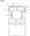
- the insulated rolling bearings disclosed in each of the patent documents are produced by forming an insulating coating such as a ceramic, a synthetic resin, or the like, on part of a bearing ring of the rolling bearing that fits with and is supported by a mating component, and is configured as shown in FIG. 34 for example.
- the rolling bearing is provided with a plurality of rolling elements 5 between an inner ring raceway 2 formed in the outer peripheral surface of an inner ring 1 and an outer ring raceway 4 formed in the inner peripheral surface of an outer ring, that enable the inner ring 1 and the outer ring 3 to rotate relative to each other.
- An insulating coating 6, which is a ceramic sprayed layer, is formed on the outer peripheral surface and the two axial end faces of the outer ring 3.
- one with a thickness dimension of 0.5 mm or more is formed conventionally by spraying droplets of ceramic material containing alumina (Al 2 O 3 ) at 94 to 95 percent by weight.
- the continuous folded over portions 9 themselves do not make contact with other parts such as the housing and the like, even if the ceramic sprayed layer is damaged, it is unlikely to cause a problem from the aspect of maintaining the insulation performance.
- a broken fragment of ceramic falls and enters the inside of the rolling bearing, it is likely to generate damage such as making an indentation in the surface or the like of the inner ring raceway 2, the outer ring raceway 4, or the rolling contact surface of each of the rolling elements 5, which is undesirable. Therefore, conventionally, the thickness dimension of the part of the ceramic sprayed layer that covers the continuous folded over portions 9 is also reduced by grinding. Grinding the surface parts of the continuous folded over portions 9 causes an increase in the cost, for no gain.
- Patent Documents 4 and 5 are known as a technique that aims at preventing a ceramic insulating coating from being damaged.
- the invention disclosed in Patent Document 4 improves the toughness of the insulating coating by impregnating a ceramic insulating coating with a synthetic resin.
- the invention disclosed in Patent Document 5 prevents the ceramic sprayed layer from breaking off, by covering a ceramic insulating coating with a metal layer.
- manufacture is difficult, so neither of them can achieve low cost.
- Patent Document 6 discloses an invention related to an electrolytic erosion preventing insulated rolling bearing having a gray alumina insulating coating containing titanium oxide (TiO 2 ) at 1 percent by weight or less.
- a gray alumina insulating coating containing titanium oxide (TiO 2 ) at 1 percent by weight or less.
- white alumina being pure alumina that does not contain titanium oxide
- the yield of the material (alumina grain) at the time of sprayed layer formation is poor, increasing the cost. Therefore, in the case of the invention disclosed in Patent Document 6, insulation performance is maintained while controlling the cost increase by using gray alumina having the above-described composition.
- gray alumina having the composition disclosed in Patent Document 6 does not always maintain sufficient insulation performance.
- white alumina it is found that, if the grain diameter of alumina sprayed is controlled appropriately, although the amount of cost increase is limited, irregular coloring occurs on the surface, resulting in a poor external appearance of the product. That is, the alumina sprayed layer has minute voids inside it in its normal condition, and in the case where moisture enters the voids, the insulation performance deteriorates.
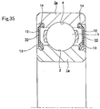
- FIGs. 35 and 36 there is a construction in which seal rings 10, being sealing devices, or shield plates 11, are provided in a rolling bearing.
- the seal rings 10 are formed by reinforcing an elastic material 13 such as rubber or the like with metal cores 12.
- the outer peripheral edges of the two seal rings 10 are fitted in fitting grooves 14 formed in the inner peripheral surfaces of the two ends of the outer ring 3 a, and the inner peripheral edges of the two seal rings 10 are pressed into sliding contact with parts of the outer peripheral surfaces of the two ends of the inner ring 1a around the entire circumference.
- FIG. 35 the seal rings 10 are formed by reinforcing an elastic material 13 such as rubber or the like with metal cores 12.
- the outer peripheral edges of the two seal rings 10 are fitted in fitting grooves 14 formed in the inner peripheral surfaces of the two ends of the outer ring 3 a, and the inner peripheral edges of the two seal rings 10 are pressed into sliding contact with parts of the outer peripheral surfaces of the two ends of the inner ring 1a around the entire circumference.
- the shield plates 11 are formed by a metal plate formed approximately circularly, and the outer peripheral edges are fitted into the fitting grooves 14 formed in the inner peripheral surfaces of the two ends of the outer ring 3a, and the inner peripheral edges are close to the outer peripheral surfaces of the two ends of the inner ring 1a.
- the space between the outer ring 3a and the inner ring 1a, where each of the rolling elements 5 are installed is isolated from the external environment.
- carbon black or silica has been added to the elastic material 13 of the seal rings 10, which are fitted into the two fitting grooves 14.
- carbon black is added to acrylonitrile-butadiene rubber or the like as the elastic material 13 to improve the friction property, wear resistance, and thermal resistance.
- carbon black is conductive, in the case where the fitting grooves 14 are not covered by the insulating coating 6 as described above, it is easy for current to flow through the two seal rings 10 from the two fitting grooves 14.
- an insulating coating made from synthetic resin with excellent insulating characteristics is formed on the outer peripheral surface of the outer ring or the inner peripheral surface of the inner ring, which are surfaces that fit with the housing or the shaft.
- synthetic resin with excellent insulating characteristics polybutylene terephthalate (PBT), polyamide 66 (PA66), polyamide 6 (PA6) and the like are recommended for example.
- PBT polybutylene terephthalate
- PA66 polyamide 66
- PA6 polyamide 6
- PA66 and PA6 have high water absorptivity, and their dimensions can change easily by absorbing moisture from the air. Therefore, they are not desirable as materials for coating the fitting surface of a bearing device, which must be accurate.
- the above-described PBT is sometimes not sufficiently thermal resistant or strength, so it is inevitably not desirable as a material for coating the interface surface.
- Patent Document 11 a technique is disclosed wherein polyphenylene sulfide (PPS) containing glass fiber is used as a material for forming an insulating coating. That is, as shown in FIG. 39 , an insulating coating 17 made from PPS containing glass fiber is formed on the outer peripheral surface and the two end faces of the metal outer ring 3b and the inner peripheral surface and the two end faces of the metal inner ring 1b, which are constituents of a rolling bearing 16.
- PPS polyphenylene sulfide
- the rolling bearing 16 which is shown in the figure, is a deep groove ball bearing, and therefore there is a plurality of metal balls 18 provided between the outer ring raceway 4 formed in the inner peripheral surface of the outer ring 3b, and the inner ring raceway 2 formed in the outer peripheral surface of the inner ring 1b.
- the outer ring 3b is fitted inside the metal housing 15a via the insulating coating 17, and the inner ring 1b is fitted outside the metal shaft, which is not shown in the figure, similarly via the insulating coating 17.
- Patent Documents 6, 12 and 13 disclose a technique wherein a ceramic insulating coating, whose coefficient of linear expansion is small, is formed on the outer peripheral surface of the outer ring and the two end faces.
- a ceramic insulating coating 17a is formed on the outer peripheral surface and the two end faces of an outer metal ring 3c, and the insulating coating 17a is covered with a metal layer 19.
- a rolling bearing 16a which is shown in the figure, is a cylindrical roller bearing.
- flange parts 20 are formed on the inner peripheral surfaces of the two ends of the outer ring 3c, and a cylindrical outer ring raceway 4a is formed on the inner peripheral surface of the central part of the outer ring 3c, which is located between the two flange parts 20. Moreover, a cylindrical inner ring raceway 2a is formed on the outer peripheral surface of the central part of the inner metal ring 1c. A plurality of cylindrical metal rollers 21 is provided between the outer ring raceway 4a and the inner ring raceway 2a.
- the insulating coating 17a is made from a ceramic whose coefficient of linear expansion is small, deformation due to heat can be suppressed. Furthermore, since the insulating coating 17a is covered with the metal layer 19, when the outer ring 3c is fitted inside the mating component such as the housing or the like by an interference fit, the insulating coating 17a can be prevented from peeling off. However, in the case of the construction disclosed in Patent Document 12 having such a configuration, the manufacturing cost increases proportionate to forming the metal layer 19.
- Patent Document 13 discloses a construction in which a first metal layer is provided on the outer peripheral surface of the outer ring and the two end faces, an insulating coating is provided on the first metal layer, and furthermore a second metal layer is provided on the insulating coating. In the case of the construction disclosed in Patent Document 13, it is also inevitable that the cost will be increased.
- the thickness (distance S) of the insulating coating is constant, the smaller the area A, the smaller the capacitance. Accordingly, in the case where an insulating coating with the same thickness is applied to rolling bearings with different bearing sizes, the capacitance of a rolling bearing with a larger bearing size, whose surface area becomes larger, is larger than that of a rolling bearing with a smaller bearing size. Therefore, in order to increase the impedance of an insulating coating applied to a rolling bearing with a larger bearing size, it is necessary to increase the thickness of the insulating coating. However, if the thickness of the film increases, the cost of the material increases. Especially, in the case where the insulating coating is made of a ceramic sprayed layer, the duration of the spraying operation increases, which also incurs an increase in the cost.
- Patent Document 6 discloses a construction in which a ceramic insulating coating consists of only one layer formed directly on the material surface.
- a ceramic insulating coating consists of only one layer formed directly on the material surface.
- the construction disclosed in Patent Document 6 is used in a large sized rolling bearing, there is a possibility that sufficient insulation performance cannot always be obtained.
- the reason is that the case of the construction disclosed in Patent Document 6 is targeted at a rolling bearing whose outer diameter is approximately 120 to 170 mm, and a large-sized rolling bearing whose outer diameter is 200 mm or more is not taken into consideration.
- the film thickness must be increased as the surface area is enlarged.
- a ceramic insulating coating is formed on a rolling bearing, in many cases it is formed on the outer ring side.
- spray nozzles can be placed on the outside of the component, improving manufacturability.
- the rolling bearing is incorporated in a rotation support portion, in many cases the inner ring and the shaft are fitted together by an interference fit, and the outer ring and the housing are fitted together by a clearance fit.
- the ceramic insulating coating is formed on the outer ring side.
- the sum of the surface areas of the outer peripheral surface of the outer ring and the two end faces is larger than the sum of the surface areas of the inner peripheral surface of the inner ring and the two end faces, so in the case of forming an insulating coating on the outer ring side, from the equation relating the capacitance and the area as mentioned previously, it is necessary to increase the film thickness in order to decrease the capacitance.
- a construction can be considered in which a ceramic insulating coating is formed on the inner peripheral surface of the inner ring, the inner ring and a shaft are fitted together by a clearance fit, and disparity between the fitted surfaces is prevented by the design of the shape of the fitted surface, or using a jig or the like.
- Patent Document 6 discloses a construction in which the ratio of titanium oxide contained in a ceramic is controlled.
- the titanium oxide is regulated to 0.25 to 0.75 percent by weight.
- the ratio of the titanium oxide is increased this much, there is a possibility that sufficient impedance cannot be ensured.
- Patent Documents 14 to 16 are documents in which a technique associated with the present invention is disclosed.
- Patent Documents 14 and 15 disclose a technique in which the dimensions of a bearing are stabilized even at a high temperature.
- Patent Document 16 discloses a case where an inner ring is made from a ceramic, and a technique in which the interference between an inner ring and a shaft is regulated.
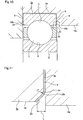
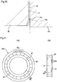
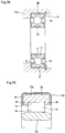
- the continuous portion 22 is a vertex with an angle of 90 degrees.
- a partial cone indented chamfer 23 which is inclined at 45 degrees with respect to the central axis of the outer ring 3, is formed at the continuous portion of the inner peripheral surface and the axial end face of the outer ring 3.
- the continuous portion 22a between the outer peripheral rim of the chamfer 23 and the axial end face is a vertex with an angle of 135 degrees.
- the continuous portions 22 and 22a are vertices.
- the current tends to concentrate at the continuous portions 22 and 22a.
- sparks occur between the continuous portions 22 and 22a, and the housing 15b. That is, it is found (it was not known prior) in the process of the research for understanding the influence of thinning the insulating coating by the present inventor, that sparks occur between the continuous portions 22 and 22a, and the housing 15b.
- Such sparks can be prevented from occurring to a certain extent by increasing the thickness of the insulating coating 6 coating the continuous portions 22 and 22a.
- the thickness exceeds 0.3 mm, sparks can be prevented to a considerable degree. Furthermore, if the thickness exceeds 0.5 mm, most of the sparks can be prevented.
- sparks can be prevented from occurring completely if the housing 15b or an outer ring spacer, which the continuous portions 22 and 22a face, is made from insulating material.
- the housing 15b or the outer ring spacer is made from insulating material.
- the present invention has been made in consideration of the above circumstances in order to realize; an electrolytic erosion preventing insulated rolling bearing, which can ensure high levels of insulation performance, durability, and low cost, at the same time, and also can have an excellent external appearance, and a manufacturing method thereof, furthermore, a construction in which, in the case where the rolling bearing is incorporated in a rotation support portion, it is possible to prevent discharge phenomena from occurring between fitting grooves and a mating component into which a bearing ring in which the fitting grooves are formed is fitted, and that in the case where a conductive elastic material is used, or a metal shield plate is used, as a seal ring, it is possible to prevent electrolytic erosion from occurring in the rolling contact parts between each raceway surface and each rolling element, which are important parts, by arranging such that current does not flow between the seal rings or shield plates and a bearing ring, or the two bearing rings, moreover, a construction in which, even in the case where a ceramic insulating coating is formed on the outer ring of a large-sized rolling bearing,
- an electrolytic erosion preventing insulated rolling bearing comprises a pair of metal bearing rings (inner ring 1 and outer ring 3 for example), which are placed concentrically with each other, and a plurality of metal rolling elements (for example balls) 5 provided between a pair of raceway surfaces (inner ring raceway 2 and outer ring raceway 4 for example) formed on the facing surfaces of the two bearing rings 1 and 3 such that they can roll freely.
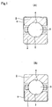
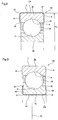
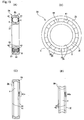
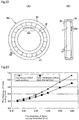
- a ceramic insulating coating 6 is coated on the surfaces other than the surface on which a raceway surface is provided, of at least one bearing ring of the two bearing rings 1 and 3, that is, in the case of a radial rolling bearing as shown in FIG. 1(A) or (B) , either one of the peripheral surfaces and the two axial end faces, and in the case of a thrust rolling bearing, either one of the axial sides and the inner and outer peripheral surfaces.
- the ceramic forming the insulating coating 6 contains alumina (Al 2 O 3 ) at 99 percent by weight or more. Furthermore, the insulating coating 6 is formed by grinding the surface of a ceramic sprayed layer formed on the surfaces other than those on which the two raceways 2 and 4 are formed. Moreover, the thickness of the ceramic sprayed layer is 0.4 mm or less, except on continuous folded over portions between adjacent surfaces, and the thickness of the insulating coating obtained by grinding the ceramic sprayed layer is 0.25 mm or more.
- the insulating coating is formed from an alumina sprayed layer containing titanium oxide (TiO 2 ) at 0.01 to 0.2 percent by weight (the main components other than titanium oxide is alumina).
- the insulating coating 6 is formed from a ceramic sprayed layer containing alumina (Al 2 O 3 ) at 97 percent by weight or more and zirconia (ZrO 2 ) at 0.5 to 2.5 percent by weight.
- the insulating coating 6 is formed from a ceramic sprayed layer
- the insulating coating 6 is formed by grinding the surface of the ceramic sprayed layer which is formed on the surfaces other than those of the raceways.
- the thickness of the ceramic sprayed layer is 0.4 mm or less, except on the continuous folded over portions between adjacent surfaces, and the thickness of the insulating coating obtained by grinding the ceramic sprayed layer is 0.25 mm or more.
- a method of controlling the thickness of the insulating coating the following method is known, for example. That is, a ceramic sprayed layer which contains alumina at 97 percent by weight or more and zirconia at 0.5 to 2.5 percent by weight, is formed on the surfaces other than those on which the raceway surfaces are provided, wherein the thickness on the parts other than the continuous folded over portions between adjacent surfaces is limited to 0.4 mm or less. Afterwards, by grinding the parts of the ceramic sprayed layer except the parts coating the folded over portions, an insulating coating of 0.25 mm or more in thickness is produced.
- an electrolytic erosion preventing insulated rolling bearing has a pair of bearing rings, a plurality of rolling elements, and a sealing device.
- bearing rings are placed concentrically with each other, and they are made from metal.
- the rolling elements are made from metal, and are provided between the pair of raceway surfaces on the facing surfaces of the two bearing rings such that they can roll freely.
- the sealing devices are fitted in fitting grooves formed in the surfaces at the two ends of part of one of the two bearing rings on which a raceway surface is formed, and isolate the place where the rolling elements are installed from the outside.
- a film with insulating characteristics is coated on the surfaces other than those on which the raceway surface is provided, of at least one of the two bearing rings.
- a film with insulating characteristics is also coated on the two fitting grooves formed in the one bearing ring.
- the sealing device is a seal ring comprising a conductive elastic material, or a metal shield plate.
- the film with insulating characteristics is a ceramic insulating coating, or an insulating coating made from a synthetic resin such as PPS (polyphenylene sulfide).
- the ceramic constituting the insulating coating contains alumina (Al 2 O 3 ) at 99 percent by weight or more.
- the insulating coating formed on the surfaces of the bearing ring other than the surface on which the raceway surface is provided is formed by grinding the surface of the ceramic sprayed layer.
- the thickness of the ceramic sprayed layer, except on continuous folded over portions between adjacent surfaces, is 0.4 mm or less, and the thickness of the insulating coating obtained by grinding the ceramic sprayed layer is 0.25 mm or more.
- the coating with insulating characteristics is an insulating coating made from a ceramic
- the insulating coating may be a sprayed layer of alumina containing either titanium oxide (TiO 2 ), or zirconia (ZrO 2 ).
- the content of alumina is 99 percent by weight or more, and the content of titanium oxide is 0.01 to 0.2 percent by weight.
- the content of alumina is 97 percent by weight or more, and the content of zirconia is 0.5 to 2.5 percent by weight.
- a ceramic sprayed layer having such a composition when it is formed on the surfaces of the bearing ring other than the surface on which the raceway surface is provided, it is also preferable to form it by grinding the surface of the ceramic sprayed layer. Moreover, in this case also, it is preferable that the thickness of the ceramic sprayed layer, except on the continuous folded over portions between adjacent surfaces, is 0.4 mm or less, and the thickness of the insulating coating obtained by grinding the ceramic sprayed layer is 0.25 mm or more.
- an insulating coating is made from a ceramic sprayed layer
- a film with insulating characteristics that coats the surfaces of the bearing ring other than those on which the raceway surfaces are provided, and the two fitting grooves is an insulating coating made from synthetic resin
- fibrous material is also possible to mix fibrous material with the synthetic resin in order to improve the strength of the insulating coating.
- fibrous material examples include glass fiber, ceramic fiber, rock wool, slag fiber, and the like.
- elastic material examples include ethylene propylene diene terpolymer (EPDM), acrylonitrile-butadiene rubber (NBR), styrene-butadiene rubber (SBR), and the like.
- EPDM ethylene propylene diene terpolymer
- NBR acrylonitrile-butadiene rubber
- SBR styrene-butadiene rubber
- filling material to the synthetic resin in order to improve the insulation performance of the insulating coating.
- examples that can be given for the filling material are powder, fibers, and whiskers of silicon carbide (SiC), aluminum nitride (AlN), beryllia (BeO), boron nitride (BN), alumina (Al 2 O 3 ), or the like.
- a ceramic sprayed layer which contains alumina at 99 percent by weight or more, is formed on the surfaces other than those on which the raceway surfaces are provided, wherein the thickness on parts other than continuous folded over portions between adjacent surfaces is limited to 0.4 mm or less. Afterwards, by grinding the parts of the ceramic sprayed layer except the parts coating the folded over portions, the insulating coating of 0.25 mm or more in thickness is produced.
- An electrolytic erosion preventing insulated rolling bearing of yet another aspect comprises; an outer ring, an inner ring, and a plurality of rolling elements, each of which is made from metal.
- the outer ring thereof has an outer ring raceway formed on its inner peripheral surface.
- the inner ring is placed medially in the outer ring, and has an inner ring raceway formed on its outer peripheral surface.
- the rolling elements are provided between the outer ring raceway and the inner ring raceway such that they can roll freely.
- a ceramic insulating coating with alumina (Al 2 O 3 ) as its main component is formed on at least the outer peripheral surface, of the surfaces other than the outer ring raceway, of the outer ring. Furthermore, an insulation resistance value of the insulating coating is 1000 M ⁇ or more, and a capacitance of the same is 27 nF or less.
- the insulating coating is an insulating coating in which the content of alumina is 99 percent by weight or more and titanium oxide (titania, TiO 2 ) is contained at 0.01 to 0.2 percent by weight, and the film thickness is 0.1 to 0.7 mm.
- the insulating coating may be an insulating coating in which the content of alumina is 97 percent by weight or more and zirconia (ZrO 2 ) is contained at 0.1 to 2.5 percent by weight, and the film thickness is 0.1 to 0.7 mm.
- At least the outer ring of the two bearing rings constituting the rolling bearing is one that has had a high temperature dimension stabilizing treatment applied or is one that is made from a high temperature dimensionally stabilized material.
- a high temperature dimension stabilizing treatment thereof is a treatment in which high temperature tempering, or double tempering, is applied to make the retained austenite amount 2 percent by volume or less as described in Patent Document 14 for example.
- examples that can be given for the high temperature dimensionally stabilized material are AISI M50 and M50NIL, being high-speed steels for high temperature bearings, or as described in Patent Document 15, a material that has higher contents of Si and Cu than normal bearing steel (SUJ2, SUJ3, etc.), and that has a retained austenite amount of 3 percent by volume or less.
- each of these embodiments is applied to a construction in which an insulating coating consists of only one layer formed directly on the surface of the outer ring, and the outer diameter of the rolling bearing is 200 mm or more.
- a bearing device of the present invention comprises; a rolling bearing, and a metal mating component that is fitted outside the rolling bearing.
- the rolling bearing thereof comprises an outer ring and an inner ring, and a plurality of rolling elements, each of which is made from metal.
- the outer ring thereof has an outer ring raceway formed on its inner peripheral surface.
- the inner ring is placed medially in the outer ring, and has an inner ring raceway formed on its outer peripheral surface.
- the rolling elements are provided between the outer ring raceway and the inner ring raceway such that they can roll freely.
- the inner ring is fitted together with the mating component by an interference fit.
- a ceramic insulating coating with alumina (Al 2 O 3 ) as its main component is formed on at least the inner peripheral surface, of the surfaces other than the inner ring raceway, of the inner ring. Furthermore, the interference between the inner ring and the mating component is regulated such that the insulating coating is not damaged.
- the inner ring contains an insulating coating that coats the inner peripheral surface, and the interference between the inner ring and the mating component (for example, a shaft) is the interference between the insulating coating that coats the inner peripheral surface of the inner ring, and the mating component.
- the interference between the inner ring and the mating component such that a hoop stress (stress in the circumferential direction) acting on the insulating coating that coats the inner peripheral surface of the inner ring is 200 N/mm 2 or less even during use. That is, the inner ring and the mating component sometimes expand thermally during use.
- the interference is determined such that the hoop stress acting on the insulating coating does not exceed 200 N/mm 2 .
- it is arranged such that the hoop stress acting on the insulating coating does not exceed 200 N/mm 2 .
- an insulation resistance value of the insulating coating is 1000 M ⁇ or more, and a capacitance is 27 nF or less.
- the insulating coating is an insulating coating in which the content of alumina is 99 percent by weight or more and titanium oxide (titania, TiO 2 ) is contained at 0.01 to 0.2 percent by weight, and the film thickness is 0.1 to 0.7 mm.
- the insulating coating may be an insulating coating in which the content of alumina is 97 percent by weight or more and zirconia (ZrO 2 ) is contained at 0.1 to 2.5 percent by weight, and the film thickness is 0.1 to 0.7 mm.
- At least the inner ring of the two bearing rings constituting the rolling bearing is one that has had a high temperature dimension stabilizing treatment applied or is one that is made from a high temperature dimensionally stabilized material.
- a high temperature dimension stabilizing treatment thereof is a treatment in which high temperature tempering, or double tempering, is applied to make the retained austenite amount 2 percent by volume or less as described in Patent Document 14 for example.
- examples that can be given for the high temperature dimensionally stabilized material are AISI M50 and M50NIL, being high-speed steels for high temperature bearings, or as described in Patent Document 15, a material that has higher contents of Si and Cu than normal bearing steel (SUJ2, SUJ3, etc.), and that has a retained austenite amount of to 3 percent by volume or less.
- the present invention is applied to a construction in which a sum of the surface areas of the outer peripheral surface of the outer ring and the two end faces is greater than or equal to 1.3 times the sum of the surface areas of the inner peripheral surface of the inner ring and the two end faces. Moreover, it is more preferable that it is applied to a construction in which the insulating coating consists of one layer formed directly on the surface of the inner ring, and an inner diameter of the rolling bearing is 100 mm or more.
- the bearing device of the present invention is incorporated in a rotation support portion of an inverter controlled electric motor or electrical generator.
- the inner ring of a rolling bearing is fitted securely on the outside of the rotating shaft of an electrical generator or the like, for example, on the outer peripheral surface of which a rotor is installed.
- an electrolytic erosion preventing insulated rolling bearing of yet another aspect comprises a pair of metal bearing rings which are placed concentrically with each other, and a plurality of metal rolling elements provided between the pair of raceway surfaces formed on the facing surfaces of the two bearing rings such that they can roll freely.
- a ceramic insulating coating is coated on the surfaces other than a raceway side peripheral surface on which a raceway surface is provided, of at least one bearing ring of the two bearing rings.
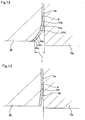
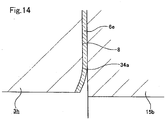
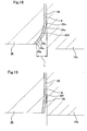
- an indented part which is indented in the axial direction away from the axial end face, is provided around the whole circumference in a part drawn towards the raceway side peripheral surface at a part in the radial direction, of the axial end face.
- the insulating coating is coated continuously from the axial end face to the indented part.
- a continuous portion between the axial end face and the indented part is a shape which is not a vertex with an apex angle of 135 degrees or less.
- the indented part is a partial cone concave shape, whose generatrix shape is a straight line.
- the continuous portion between the indented part and the axial end face is a partial circle shape convex surface whose cross-section has a curve radius of 1 mm or more.
- the indented part is a plurality of joined partial cone indented surfaces, whose angles of inclination with respect to the central axis of the coated bearing ring are different, and the generatrix shapes of which are straight lines. Intersect angles between the adjacent partial cone indented surfaces, and apex angles of the continuous portions between one of the partial cone indented surfaces and the axial end face are 150 degrees or more.
- the indented part is a single partial cone concave shape, whose generatrix shape is a straight line.
- An apex angle of the continuous portion between the indented part and the axial end face is 150 degree or more.
- the indented part is a convex surface, whose generatrix shape is a partial circle.
- a generatrix of the axial end face is located tangentially to the generatrix of the indented part.
- the rim drawn towards the raceway side peripheral surface is located 1mm or more axially inside from the axial end face of the coated bearing ring (the surface of the insulating coating that coats it, or the surface of the housing, which is a mating surface facing the axial end face).
- an electrolytic erosion preventing insulated rolling bearing of yet another aspect comprises a metal outer ring having an outer ring raceway on its inner peripheral surface, a metal inner ring having an inner ring raceway on its outer peripheral surface, and placed on the inner diameter side of the outer ring concentrically with the outer ring, and a plurality of metal rolling elements provided between the inner ring raceway and the outer ring raceway such that they can roll freely.
- At least one of the outer ring and the inner ring is a coated bearing ring, and an insulating coating is coated on the surfaces of the coated bearing ring other than the raceway side peripheral surface on which a raceway surface is provided, being the outer ring raceway or the inner ring raceway.
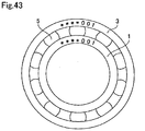
- characters or reference symbols indicating property or history information of the rolling bearing containing the coated bearing ring having the raceway side peripheral surface concerned are marked on part of the raceway side peripheral surface, which is away from the raceway surface.
- this electrolytic erosion preventing insulated rolling bearing is implemented, for example, it is provided with a cage for retaining the rolling elements.
- the characters or reference symbols are marked on a part that is covered by the cage.
- an indented part which is indented in the axial direction away from the axial end face, is provided around the whole circumference in a part drawn towards a peripheral surface in which the raceway surface is provided, at a part in the radial direction, of the axial end face.
- the insulating coating is coated continuously from the axial end face to the indented part.
- the continuous portion between the axial end face and the indented parts is not a vertex with an apex angle of 135 degrees or less.
- the apex angle is an angle of 135 degrees or more (for example, 150 degrees or more), or the continuous portion is a convex surface whose cross-section is a circular arc.
- the rim drawn towards the peripheral surface on which the raceway surface is provided is located 1 mm or more axially inside from the axial end face.
- a bearing ring of only one of the outer ring and the inner ring is a coated bearing ring.
- an insulating coating is coated on the surfaces other than the raceway side peripheral surface on which the raceway surface, being the outer ring raceway or the inner ring raceway, is provided.
- the other bearing ring of the outer ring and the inner ring is an exposed bearing ring, none of the surfaces of which is coated with an insulating coating.
- characters or reference symbols indicating property or history information of the rolling bearing that contains the exposed bearing ring are marked on part of the surface of the exposed bearing ring, which is a part other than the raceway surface formed on the peripheral surface of the exposed bearing ring.
- this electrolytic erosion preventing insulated rolling bearing it is preferable that second characters or reference symbols corresponding to the characters or reference symbols marked on the surface of the exposed bearing ring, are marked on part of the peripheral surface of the coated bearing ring on which the raceway surface is provided, away from the raceway surface.
- this electrolytic erosion preventing insulated rolling bearings it is also possible to use the construction in which a cage is provided, an indented part is formed, and the continuous portion between the axial end surface and the indented part is not a vertex with an apex angle.
- the electrolytic erosion preventing insulated rolling bearing, and the manufacturing method thereof, of the present invention it is possible to ensure high levels of insulation performance, durability, and low cost, at the same time.
- a ceramic sprayed layer that contains alumina at 99 percent by weight or more is used, but such a ceramic sprayed layer has a comparatively high electrical resistivity (excellent insulating characteristics). Accordingly, if it is ensured that the thickness of the insulating coating after grinding is 0.25 mm or more, provided that the application is for rotation support portion of a rotating shaft of an electric motor for general use or for rail car, or for a rotation support portion of a rotating shaft for an electrical generator, or furthermore for a rotation support portion of a general purpose motor for general industry or the like, a sufficient electrolytic erosion prevention effect can be ensured.
- the thickness of the ceramic sprayed layer is 0.4 mm or less except on the continuous folded over portions between adjacent surfaces, and the thickness of the insulating coating obtained by grinding the ceramic sprayed layer is 0.25 mm or more, it is possible to ensure high levels of insulation performance, durability, and low cost, at the same time.
- a ceramic sprayed layer which contains alumina at greater than or equal to 97 percent by weight and zirconia at greater than or equal to 0.5 to 2.5 percent by weight, is used.
- a ceramic sprayed layer has a comparatively high electrical resistivity (excellent insulating characteristics). Therefore, if it is ensured that the thickness of the insulating coating after grinding is greater than or equal to 0.25 mm, provided that the application is for a rotating shaft of an electric motor for general use or for railroad rocking stock, or for a rotation support portion of a rotating shaft for an electrical generator, a sufficient electrolytic erosion prevention effect can be ensured.
- the thickness of the insulating coating after grinding is greater than or equal to 0.25 mm, even if the thickness of the ceramic sprayed layer before grinding is less than or equal to 0.4 mm, a sufficient grinding allowance can be ensured. If the thickness of the ceramic sprayed layer can be limited to less than or equal to 0.4 mm, the thickness of the ceramic sprayed layer coating the two continuous folded over portions between adjacent surfaces can be limited to less than 0.5 mm (furthermore less than or equal to 0.48 mm).
- the thickness of the ceramic sprayed layer is approximately 0.5 mm (furthermore 0.48 mm), the thickness dimension is not excessive, so it is difficult for damage such as cracks, chips or the like to occur even if it is left as it is (even if the thickness dimension is not reduced by grinding). Accordingly, the time and effort for grinding parts of the ceramic sprayed layer which coat the continuous folded over portions, are eliminated and hence the cost can be reduced. Moreover, cost reduction can also be achieved by keeping the thickness of the ceramic sprayed layer thinner ⁇ formerly greater than or equal to 0.5 mm (typically about 0.6 to 0.7 mm) to less than or equal to 0.4 mm ⁇ .
- the electrolytic erosion preventing insulated rolling bearing of the second, third, seventh and eighth aspects of the invention by incorporating either one of titanium oxide and zirconia in an alumina sprayed layer, it is possible to ensure high levels of insulation performance, durability, low cost, and excellent external appearance at the same time.
- the content of alumina is 99 percent by weight or more, and the titanium oxide contained in the alumina sprayed layer is 0.01 to 0.2 percent by weight, or the content of alumina is 97 percent by weight or more, and the content of zirconia contained in the alumina sprayed layer is 0.5 to 2.5 percent by weight, it is easier to ensure an excellent external appearance. That is, for a ceramic sprayed layer with alumina as its main component, in the case of white alumina which does not contain titanium oxide or the like, the insulation performance is excellent, but the external appearance deteriorates when it is sealed with synthetic resin.
- the content of the titanium oxide is limited to 0.01 to 0.2 percent by weight, or the content of the zirconia is limited to within 0.5 to 2.5 percent by weight.
- the yield of the material (alumina grains) when forming a sprayed layer deteriorates slightly.
- alumina of particle sizes 10 to 50 ⁇ m, and average particle size 15 to 25 ⁇ m is used, the deposition efficiency of alumina forming the ceramic sprayed layer is improved, and at the same time the accuracy related to the thickness dimension of the ceramic sprayed layer is improved, thus enabling the increase in cost to be kept down. That is, a reduction in the material cost due to the improvement of the deposition efficiency, and simplification of finishing (shortening of finishing time) due to the improvement of the dimensional accuracy, enable the cost of manufacturing an electrolytic erosion preventing insulated rolling bearing to be inexpensive.
- the adhesion of the alumina sprayed layer can be improved. As a result, sufficient durability can be ensured.
- the electrolytic erosion preventing insulated rolling bearing of the present invention in the case where the rolling bearing is installed in a rotation support portion, discharge phenomena can be prevented from occurring between the fitting grooves and a mating component into which the bearing ring in which the fitting grooves are formed is fitted. That is, since the insulating coating covers the fitting grooves, even if the distance between the surface of a fitting groove and the surface of the mating component is short, discharge phenomena can be prevented from occurring between the surfaces.
- a seal ring to be fitted in the fitting groove is a seal ring containing a conductive elastic material, for example having carbon black added, or even in the case where a metal shield plate is used, current can be prevented from flowing through the seal ring or the shield plate. Moreover, even if discharge phenomena occur between the surface of the mating component and the seal ring or the shield ring, current does not flow to the bearing ring side. Accordingly, electrolytic erosion can be prevented from occurring at least between the two bearing rings and the rolling elements.
- the coating with insulating characteristics is an insulating coating made from synthetic resin, and a fibrous material as described previously is mixed in the insulating coating, the strength of the insulating coating is ensured, thus enabling the creep resistance to be improved. Furthermore, in the case where an elastic material as mentioned previously is mixed in the insulating coating, the impact resistance can be improved. Moreover, in the case where a filling material as mentioned previously is mixed in the insulating coating, the insulation performance can be improved, and also the heat transfer properties can be improved, thus enabling the increase in temperature of the rolling bearing to be controlled.
- the electrolytic erosion preventing insulated rolling bearing of the present invention even in the case where a ceramic insulating coating is formed on the outer ring of a large sized rolling bearing, sufficient insulation performance of the insulating coating can be ensured.
- the material and film thickness of the ceramic insulating coating with alumina as its main component such that the insulation resistance value of the insulating coating is 1000 M ⁇ or more, and the capacitance of the same is 27 nF or less, even in the case where the insulating coating is formed on the outer ring of a large sized rolling bearing, which has a large surface area, a rolling bearing with high impedance can be achieved.
- a range of data such as experimental data obtained by the inventor, if the capacitance exceeds 27 nF, sometimes sufficient impedance (insulation resistance value) cannot be obtained. Therefore, by making the capacitance of the insulating coating 27 nF or less, preferably 25 nF or less, or more preferably 23 nF or less, sufficient insulation performance of the insulating coating can be ensured.
- the bearing device of the present invention using a construction in which the ceramic insulating coating is formed on the bearing ring, it is possible to realize an inexpensive construction with high impedance (insulation resistance value).
- the insulating coating is formed on the inner ring side, it is possible to make the area on which the coating is formed small. As a result, the capacitance of the insulating coating can be made low, and the impedance can be made high. Furthermore, since the film thickness does not need to be made large in order to reduce the capacitance, the manufacturing cost can be reduced. In the case of a construction where the inner ring is fitted into the mating component by an interference fit, there is a possibility that damage such as cracks occurs in the brittle ceramic insulating coating. However, if the interference between the inner ring and the mating component is controlled such that the insulating coating is not damaged during use, such a problem does not occur.
- the interference between the inner ring and the mating component is controlled such that the hoop stress acting on the insulating coating, which coats the inner peripheral surface of the inner ring, is 200 N/mm 2 or less even during use, it is possible to prevent damage such as cracks from occurring on the insulating coating, effectively.
- the insulating coating is formed as an insulating coating in which the content of alumina is 99 percent by weight or more and titanium oxide is contained at 0.01 to 0.2 percent by weight, and the film thickness is between 0.1 and 0.7 mm, it is possible to obtain an inexpensive insulating coating having high impedance as described above. That is, the higher the purity of the alumina, the higher the impedance can be. However, increasing the purity of the alumina leads to an increase in the manufacturing cost. In response, if the content of titania incorporated unavoidably is limited to within 0.01 to 0.2 percent by weight, an insulating coating with high impedance can be obtained while minimizing the increase in cost.
- the thickness of the insulating coating should be 0.1 to 0.7 mm, and preferably, 0.2 to 0.5 mm.
- the insulating coating is formed by an insulating coating in which the content of alumina is 97 percent by weight or more and zirconia is contained at 0.1 to 2.5 percent by weight, the purity of alumina is increased, thus enabling the impedance to be increased, and also the bond strength of the insulating coating to the metal surface can be improved. That is, in the case where the content of zirconia of high strength and high toughness is less than 0.1 percent by weight, the bond strength cannot be improved sufficiently. On the other hand, in the case where the content of zirconia is greater than 2.5 percent by weight, the purity of the alumina becomes too low, leading to a drop in the impedance.
- the thickness of the insulating coating is 0.1 to 0.7 mm, and preferably 0.2 to 0.5 mm, a balance can be found between ensuring the insulation resistance and controlling manufacturing costs.
- the insulating coating is formed by plasma spraying
- the outer ring of the two bearing rings constituting the rolling bearing is one that has had a high temperature dimension stabilizing treatment applied or one that is made from a high temperature dimensionally stabilized material
- the dimensional accuracy of the outer ring can be ensured. That is, by applying a high temperature dimension stabilizing treatment, even in the case where a high localized temperature is reached due to plasma spraying, the dimensional accuracy of the outer ring can be maintained.
- the present invention is applied to a construction in which the outer diameter of a rolling bearing (outer ring constituting it) is 200 mm or more, the effects of the invention can be obtained more conspicuously. That is, since a rolling bearing whose diameter is 200 mm or more has a significantly large outer ring surface area, even if the insulating coating is formed without consideration of the size of the surface area, there is a possibility that sufficient insulation performance cannot be ensured. Conversely, in the present invention, by controlling the capacitance of the insulating coating, even if the surface area is large, the impedance is increased reliably, thus enabling sufficient insulation performance to be ensured.
- the manufacturing cost can be reduced.
- an insulating coating incorporating zirconia is used, the adhesion between the insulating coating and the outer ring is increased, so that even if a metal layer is not provided, the insulating coating can be prevented from peeling off.
- the insulating coating is formed by plasma spraying
- a high temperature dimension stabilizing treatment is applied to at least the inner ring of the two bearing rings constituting a rolling bearing, or high temperature dimensionally stabilized material is used, the dimensional accuracy of the inner ring can be ensured. That is, by applying the above-mentioned high temperature dimension stabilizing treatment, or by using high temperature dimensionally stabilized material, even in the case where a high localized temperature is reached due to the high temperature plasma sprayed gas, the dimensional accuracy of the inner ring can be maintained.
- the present invention is applied to a construction in which the sum of the surface areas of the outer peripheral surface and the two end faces of the outer ring is greater than or equal to 1.3 times the sum of the surface areas of the inner peripheral surface and the two end faces of the inner ring, the effects of the invention can be obtained more conspicuously. That is, if there is a large difference in surface area between the outer ring and the inner ring, in the case where the insulating coating is formed on the inner ring side, compared with the case where an insulating coating of the same thickness is formed on the outer ring side, the capacitance can be reduced by a greater proportion. Furthermore, higher impedance can be achieved, and also the cost reduction effect is increased.
- the present invention is applied to a construction in which the inner diameter of the rolling bearing (inner ring constituting it) is 100 mm or more, good levels of high impedance and cost reduction can be achieved at the same time.
- diameter series numbers 3, 2 & 0 are commonly used.
- the surface area of the outer ring is larger than the surface area of the inner ring by 30 percent or more.
- the insulating coating is only one layer, compared with the constructions described in Patent Documents 12 and 13, the manufacturing cost can be reduced. Furthermore, as described previously, if an insulating coating incorporating zirconia is used, the adhesion between the insulating coating and the inner ring is increased, so that even if a metal layer is not provided, the insulating coating can be prevented from peeling off.
- an electrolytic erosion preventing insulated rolling bearing of the present invention or the bearing device of the present invention, is incorporated in the rotation support portion of an inverter controlled electric motor or electrical generator, the effects of the invention can be obtained more effectively. That is, as described earlier, since an inverter controlled electric motor or the like tends to increase the carrier frequency of the inverter, the current flowing to the rolling bearing has a high frequency. Therefore, the insulating coating is required to have high impedance (high insulation resistance value). Conversely, in the case of each of the invention, as described above, since high impedance can be realized, they are suitable for inverter controlled electric motors and the like.
- the electrolytic erosion preventing insulated rolling bearing of the present invention even in the case where current flows between the coated bearing ring and the mating component that makes contact with the coated bearing ring, the concentration of current at the continuous portion between the axial end face and the indented part of the coated bearing ring is limited (excessive current does not concentrate at a vertex). Therefore, a voltage that is applied to an electrolytic erosion preventing insulated rolling bearing installed in a rotation support portion of a rotating shaft of an electric motor for general purposes, or for rail car, or a rotating shaft of an electrical generator, would be unlikely to produce sparking between the continuous portion and the mating component. As a result, it is possible to ensure sufficient durability of the electrolytic erosion preventing insulated rolling bearing.
- concentration of current at the continuous portion between the axial end face and the indented part of the coated bearing ring is limited so that the durability of the electrolytic erosion preventing insulated roller bearing can be prevented from being reduced due to sparking occurring.
- marking of characters or reference symbols indicating property or history information is provided without reducing the electrolytic erosion prevention capabilities. That is, since the marking is provided on part of the surface of the bearing ring that is not coated by the insulating, coating, that is, a part for which insulation from its mating surface is not required, the electrolytic erosion preventing capabilities are not damaged by the existence of the marking. Therefore, the fundamental capabilities of the electrolytic erosion preventing insulated rolling bearing can be ensured, while the quality of the electrolytic erosion preventing insulated rolling bearing can be controlled effectively.
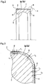
- FIGs. 2 and 3 show a first example of an embodiment of the present invention.
- an insulating coating 6a is formed on the outer peripheral surface 7 and two axial end faces 8 of an outer ring 3 constituting a single row deep groove radial ball bearing.
- the insulating coating 6a is a ceramic sprayed layer formed by spraying ceramic droplets containing alumina at 99 percent by weight or more on the outer peripheral surface 7 and the two axial end faces 8. It is preferable that the insulating coating 6a is an alumina sprayed layer containing titanium oxide at 0.01 to 0.2 percent by weight.
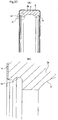
- the insulating coating 6a being such a ceramic sprayed layer, coats the outer peripheral surface 7, the two axial end faces 8, and also the surfaces of the quarter circle cross-section continuous folded over portions 9, which join the two axial edges of the outer peripheral surface 7, and the outer peripheral rims of the two axial end faces 8.
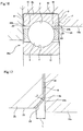
- the thickness dimensions T7, T8 and T9 (refer to FIG. 3 ) of the insulating coating 6a, which coats each of the surfaces
- the thickness dimensions T7 and T8 of the parts coating the surfaces of the outer peripheral surface 7 and the two axial end faces 8 are limited to 0.4 mm or less.
- the thickness dimension T9 of the parts coating the surfaces of the two continuous folded over portions 9 is limited to 0.48 mm or less.
- each of the parts becomes a smooth surface, so that the surfaces 7 and 8 and the inner surface of the housing that the outer ring 3 is fitted inside, can make a close contact.
- a grinding allowance ⁇ as shown in FIG. 3 is removed from part (crosshatched part of FIG. 3 ) of the surface of the insulating coating 6a coating the surfaces 7 and 8, so that the thickness dimension of the insulating coating 6a becomes thinner than that in the state in which the ceramic sprayed layer was formed.
- parts of the insulating coating 6a, which coat the surfaces of the two continuous folded over portions 9, are not ground, and remain as they are (ceramic droplets as sprayed).
- An electrolytic erosion preventing insulated rolling bearing as described above can ensure high levels of insulation performance of the insulating coating 6a, durability, and low cost, at the same time.
- the insulation performance can be ensured by using a ceramic sprayed layer to form the insulating coating 6a containing alumina at 99 percent by weight or more. That is, since a ceramic sprayed layer containing alumina at 99 percent by weight or more has a high electrical resistivity (excellent insulating characteristics), if it is ensured that the thickness of the insulating coating (in a useable state) after grinding is 0.25 mm or more, provided that the application is for a rotating support portion of the rotating shaft of an electric motor for general use or for rail car, or of a rotation shaft for an electrical generator, whose potential difference is up to about 3000 V, a sufficient electrolytic erosion prevention effect can be ensured. For example, in the case where the thickness dimension of an insulating coating after grinding is 0.3 mm, it is possible to ensure an insulation resistance of 5000 M ⁇ or more under the condition of 1000 V applied.
- a sufficient grinding allowance (approximately 0.15 mm maximum) can be ensured. That is, in order to make the contact of the surface of the insulating coating 6a and the inner surface of the housing even, to stabilize the attitude of the outer ring 3 and prevent excessive force from being applied to part of the insulating coating 6a, it is necessary to grind the parts coating the surfaces of the outer peripheral surface 7 and the two axial end faces 8.
- the necessary grinding allowance is 0.15 mm or less, so that even if the thickness of the ceramic sprayed layer before grinding is limited to 0.4 mm or less, it can be ensured that the thickness of the insulating coating 6a after grinding is 0.25 mm or more.
- the thickness dimension T9 of parts coating the surfaces of the two continuous folded over portions 9 can be limited to 0.48 mm or less. That is, ceramic droplets sprayed on the outer peripheral surface 7 from the outside in the radial direction, and ceramic droplets sprayed on the two axial end faces 8 from the outside in the axial direction, adhere to the two continuous folded over portions 9. Consequently, the thickness dimension of the ceramic sprayed layer coating the two continuous folded over portions 9 is greater than the thickness dimension of the ceramic sprayed layer coating the outer peripheral surface 7 and the two axial end faces 8.
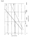
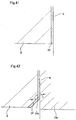
- the proportionate increase in the thickness dimension of the ceramic sprayed layer coating the two continuous folded over portions 9 becomes considerable as the thickness dimension of the ceramic sprayed layer coating each of the surfaces 7 and 8 increases as shown in FIG 23 , described later.
- the amount of increase in the thickness dimension of the ceramic sprayed layer coating the two continuous folded over portions 9 remains approximately 1.2 times (0.48 mm).
- the proportionate increase in the thickness dimension of the ceramic sprayed layer coating the two continuous folded over portions 9 reaches approximately 1.3 times (0.65 mm).
- the thickness dimension of the ceramic sprayed layer coating each of the surfaces 7 and 8 is limited to 0.4 mm or less, the thickness dimension of the ceramic sprayed layer coating the two continuous folded over portions 9 can be limited to 0.48 mm or less. If the thickness of the ceramic sprayed layer is approximately 0.48 mm, the thickness dimension is not excessive, so it is difficult for damage such as cracks, chips or the like to occur even if it is left as it is (even if the thickness dimension is not reduced by grinding). Accordingly, the time and effort for grinding parts of the insulating coating 6a, which coat the two continuous folded over portions 9, are eliminated and hence the cost can be reduced.
- titanium oxide at over 0.2 percent by weight is incorporated, the thickness of the ceramic sprayed layer required to ensure the necessary insulation performance increases. Therefore, it is preferable to limit the content of the titanium oxide to within 0.01 to 0.2 percent by weight.
- the yield of the material (alumina grains) when forming a sprayed layer deteriorates slightly.
- alumina of particle sizes 10 to 50 ⁇ m, and average particle size 15 to 25 ⁇ m is used, the deposition efficiency of the alumina forming the ceramic sprayed layer is improved, and at the same time the accuracy related to the thickness dimension of the ceramic sprayed layer is improved, thus enabling the increase in the cost to be kept down. That is, a reduction in the material cost due to the improvement of the deposition efficiency, and simplification of finishing (shortening of finishing time) due to the improvement of the dimensional accuracy, enable the cost of manufacturing an electrolytic erosion preventing insulated rolling bearing to be inexpensive.
- an insulating coating 6b is formed on the outer peripheral surface 7 and two axial end faces 8 of an outer ring 3 constituting a single row deep groove radial ball bearing.
- the insulating coating 6b is a ceramic sprayed layer formed by spraying ceramic droplets containing alumina at 97 percent by weight or more and zirconia at 0.5 to 2.5 percent by weight, using plasma spraying.
- the insulating coating 6b being such a ceramic sprayed layer, coats the outer peripheral surface 7 and the two axial end faces 8, and also the surfaces of the quarter circle cross-section continuous folded over portions 9, which join the two axial edges of the outer peripheral surface 7, and the outer peripheral rims of the two axial end faces 8.
- the thickness dimensions T7, T8 and T9 (refer to FIG. 3 ) of the insulating coating 6b
- the thickness dimensions T7 and T8 of the parts coating the surfaces of the outer peripheral surface 7 and the two axial end faces 8 are limited to 0.4 mm or less.
- the thickness dimension T9 of the parts coating the surfaces of the two continuous folded over portions 9 is limited to less than 0.5 mm.
- each of the parts becomes a smooth surface, so that the surfaces 7 and 8 and the inner surface of the housing that the outer ring 3 is fitted inside, can make a close contact.
- a grinding allowance ⁇ as shown in FIG. 3 is removed from part (crosshatched part of FIG. 3 ) of the surface of the insulating coating 6b coating the surfaces 7 and 8, so that the thickness dimension of the insulating coating 6b becomes thinner than that in the state in which the ceramic sprayed layer was formed.
- parts of the insulating coating 6b, which coat the surfaces of the two continuous folded over portions 9, are not ground, and remain as they are (ceramic droplets as sprayed).
- An electrolytic erosion preventing insulated rolling bearing as described above can ensure high levels of insulation performance of the insulating coating 6b, durability, and low cost, at the same time.
- the insulation performance can be ensured by using a ceramic sprayed layer to form the insulating coating 6b containing alumina at 97 percent by weight or more. That is, since a ceramic sprayed layer containing alumina at 97 percent by weight or more has a high electrical resistivity (excellent insulating characteristics), if it is ensured that the thickness of the insulating coating (in a useable state) after grinding is 0.25 mm or more, provided that the application is for a rotating support portion of the rotating shaft of an electric motor for general use or for rail car, or of a rotating shaft for an electrical generator, whose potential difference is up to about 3000 V, a sufficient electrolytic erosion prevention effect can be ensured. For example, in the case where the thickness dimension of an insulating coating after grinding is 0.25 mm, it is possible to ensure an insulation resistance of 5000 M ⁇ or more under the condition of 1000 V applied.
- a sufficient grinding allowance (approximately 0.15 mm maximum) can be ensured. That is, in order to make the contact of the surface of the insulating coating 6b and the inner surface of the housing even, to stabilize the attitude of the outer ring 3 and prevent excessive force from being applied to part of the insulating coating 6b, it is necessary to grind the parts coating the surfaces of the outer peripheral surface 7 and the two axial end faces 8.
- the necessary grinding allowance is 0.15 mm or less, so that even if the thickness of the ceramic sprayed layer before grinding is limited to 0.4 mm or less, it can be ensured that the thickness of the insulating coating 6b after grinding is 0.25 mm or more.
- the thickness dimension T9 of parts coating the surfaces of the two continuous folded over portions 9 can be limited to less than 0.5 mm. That is, ceramic droplets sprayed on the outer peripheral surface 7 from the outside in the radial direction, and ceramic droplets sprayed on the two axial end faces 8 from the outside in the axial direction, adhere to the two continuous folded over portions 9. Consequently, the thickness dimension of the ceramic sprayed layer coating the two continuous folded over portions 9 is greater than the thickness dimension of the ceramic sprayed layer coating the outer peripheral surface 7 and the two axial end faces 8.
- the thickness dimension of the ceramic sprayed layer coating each of the surfaces 7 and 8 is limited to 0.4 mm or less, the thickness dimension of the ceramic sprayed layer coating the two continuous folded over portions 9 can be limited to less than 0.5 mm. If the thickness of the ceramic sprayed layer is approximately 0.5 mm, the thickness dimension is not excessive, so it is difficult for damage such as cracks, chips or the like to occur even if it is left as it is (even if the thickness dimension is not reduced by grinding). Accordingly, the time and effort for grinding parts of the insulating coating 6b, which coat the two continuous folded over portions 9, are eliminated and hence the cost can be reduced.
- the content of the zirconia is preferable to within 0.5 to 2.5 percent by weight.
- the yield of the material (alumina grains) when forming a sprayed layer deteriorates slightly.
- alumina of particle sizes 10 to 50 ⁇ m, and average particle size 15 to 25 ⁇ m is used, the deposition efficiency of the alumina forming the ceramic sprayed layer is improved, and at the same time the accuracy related to the thickness dimension of the ceramic sprayed layer is improved, thus enabling the increase in the cost to be kept down. That is, a reduction in the material cost due to the improvement of the deposition efficiency, and simplification of finishing (shortening of finishing time) due to the improvement of the dimensional accuracy, enable the cost of manufacturing an electrolytic erosion preventing insulated rolling bearing to be inexpensive.
- the adhesion of the ceramic sprayed layer can be improved. If in this manner the adhesion of the ceramic sprayed layer is improved, the ceramic sprayed layer is unlikely to peel off, and hence sufficient durability can be ensured.
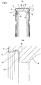
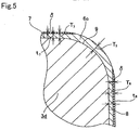
- FIGs. 4 to 6 show a third example of an embodiment of the present invention.
- the characteristic point of the present example is that even in the case where an outer ring 3d is fitted into a metal housing 15, in order to prevent discharge phenomena from occurring between fitting grooves 14 formed in the surface of the housing 15 and the inner peripheral surfaces of the two ends of the outer ring 3d, an insulating coating 6c also coats the two fitting grooves 14.
- the other structures and effects are similar to those in the conventional construction shown in FIGs. 34 to 36 . Therefore, parts similar to the construction shown in FIG. 34 to 36 and duplicate figures are omitted or simplified, and hereunder is a description focusing on the points of the present example and the parts that differ from the conventional construction.
- the ceramic insulating coating 6c in addition to the outer peripheral surface 7 of the outer ring 3d, and the two axial end faces 8 of the outer ring 3d, the ceramic insulating coating 6c also coats the surfaces of the two fitting grooves 14.
- the insulating coating 6c is a ceramic sprayed layer formed by spraying, for example by plasma spraying, ceramic droplets containing alumina at 99 percent by weight or more, onto the outer peripheral surface 7 and the two axial end faces 8, and also the two fitting grooves 14.
- the insulating coating 6c being such a ceramic sprayed layer, in addition to the outer peripheral surface 7, the two axial end faces 8, and the two fitting grooves 14, also coats the surfaces of the quarter circle cross-section continuous folded over portions 9, which join the two axial direction edges of the outer peripheral surface 7, and the outer peripheral rims of the two axial end faces 8. Moreover, the portions which join the inner peripheral edges of the two axial end faces 8 and the two axial ends of the two fitting grooves 14 are also coated with the insulating coating 6c.
- the parts from the outer peripheral surface 7, the continuous folded over portions 9, and the two axial end faces 8, to the two fitting grooves 14 of the surface of the outer ring 3d are coated by the insulating coating 6c. Furthermore, parts of the surfaces of the two fitting grooves 14 are coated by the insulating coating 6c up to the internal rims of the side faces 24 inside, in the axial direction, of the two fitting grooves 14.
- the thickness dimensions T7, T8 and T9 (refer to FIG. 5 ) of the insulating coating 6c that coats the aforementioned respective faces 7, 8 and 9 except for the two fitting grooves 14, the thickness dimensions T7 and T8 of the parts coating the surfaces of the outer peripheral surface 7 and the two axial end faces 8 are limited to 0.4 mm or less.
- the thickness dimension T9 of the parts coating the surfaces of the two continuous folded over portions 9 is limited to less than 0.5 mm (preferably 0.48 mm or less).
- each of the parts becomes a smooth surface, so that the surfaces 7 and 8 and the inner surface of the housing 15 (refer to FIG. 6 ) being the matching member, that the outer ring 3d is fitted inside, can make a close contact.
- a grinding allowance ⁇ as shown in FIG. 5 is removed from part (crosshatched part of FIG. 5 ) of the surface of the insulating coating 6c coating the surfaces 7 and 8, so that the thickness dimension of the insulating coating 6c becomes thinner than that in the state in which the ceramic sprayed layer was formed.
- parts of the insulating coating 6c, which coat the surfaces of the two continuous folded over portions 9, are not ground in order to reduce cost, and remain as they are (ceramic droplets as sprayed).
- the thickness of the insulating coating 6c coating the two fitting grooves 14 is at least 0.25 mm or more. That is, since the shapes of the two fitting grooves 14 are complex compared with those of the outer peripheral surface 7 and the two axial end faces 8, it is difficult to control the thickness of the insulating coating 6c. Accordingly, dispersion is likely to occur in the thickness of the insulating coating 6c coating the surfaces of the two fitting grooves 14. However, due to recent improvements in the spraying technique, it is possible to control the thickness to a certain extent. Therefore, by careful attention during spraying, it is preferable to make the thickness of the insulating coating 6c coating the two fitting grooves 14 to 0.25 mm or more. In this manner, if it can be ensured that the thickness of the coating is 0.25 mm or more, sufficient insulation performance can be ensured.
- sealing devices to be fitted in the two fitting grooves 14 are seal rings 10 (refer to FIG. 35 ) formed by reinforcing elastic materials 13 with metal cores 12, the elastic materials 13 are fitted in the two fitting grooves 14. Accordingly, even if the insulating coating 6c is slightly thicker than that on the outer peripheral surface 7 and the two axial end faces 8, being parts supported inside the housing 15, it is difficult for damage such as cracks, chips and the like to be caused. Therefore, in the case where the two seal rings 10 are fitted in the two fitting grooves 14, the thickness of the insulating coating 6c coating the two fitting grooves 14 may be increased within a range in which it does not cause the functional problem described next. However, in the case where shield plates 11 (refer to FIG.
- the thickness of the insulating coating 6c coating the two fitting grooves 14 is preferable to limit the thickness of the insulating coating 6c coating the two fitting grooves 14 to 0.5 mm or less by devising a suitable spraying method, or by grinding the sprayed layer.
- the components fitted in the two fitting grooves 14 are either seal rings 10 or shield plates 11, it is preferable to control the dimensions of the two fitting grooves 14 before spraying, with consideration of the dimensions after spraying. That is, as described above, in the case where the insulating coating 6c is sprayed on the two fitting grooves 14, it is difficult to control the thickness. Accordingly, it is first checked how the sprayed layer is formed, and then the dimensions of the two fitting grooves 14 before forming the insulating coating 6c are controlled in order to prevent any problem from occurring, even after spraying, when the seal rings 10 or the shield plates 11 are attached.
- the spaces between the two inside faces of the fitting grooves 14 after the insulating coating 6c is formed, in which the two components 10 and 11 are fitted, are prevented from being too large, or the spaces in which the two components 10 and 11 are fitted are prevented from being too small. Then, the seal rings 10 or the shield plates 11 are prevented from detaching easily because the seal rings 10 or the shield plates 11 cannot be inserted to the full extent, and excessive force is prevented from being required when the seal rings 10 or the shield plates 11 are fitted.
- an electrolytic erosion preventing insulated rolling bearing of the present example constructed as above in the case where a rolling bearing is installed in a rotation support portion, it is possible to prevent discharge phenomena occurring between the fitting grooves 14 and the housing 15, in which the outer ring 3d in which the two fitting grooves 14 are formed, is fitted. That is, in the case of the conventional construction as described previously, as shown in FIG. 38 (B) , since the insulating coating is not formed in the fitting grooves 14, the distance L1 between part of the surface of the housing 15 and part of the surface of the outer ring 3 a, which is not coated by the insulating coating (that is, the rim of the fitting groove 14 in the axial direction), is short.
- the insulation performance can be ensured by using a ceramic sprayed layer to form the insulating coating 6c containing alumina at 99 percent by weight or more. That is, since a ceramic sprayed layer containing alumina at 99 percent by weight or more has a high electrical resistivity (excellent insulating characteristics), if it is ensured that the thickness of the insulating coating 6c in a useable state is 0.25 mm or more, a sufficient electrolytic erosion prevention effect can be ensured, even if the potential difference is large.
- titanium oxide In order to prevent irregular coloring from occurring on a ceramic sprayed layer accompanying sealing with synthetic resin, it is preferable to incorporate titanium oxide at 0.01 to 0.2 percent by weight in the ceramic sprayed layer. In order to make the color of the surface gray (ash color), it is preferable that the content of titanium oxide is 0.02 to 0.2 percent by weight. Furthermore, in order to maintain the yield of the material (alumina grains) when forming a sprayed layer, it is preferable to use alumina of particle sizes 10 to 50 ⁇ m, and average particle size 15 to 25 ⁇ m.
- the insulating coating 6c coats the outer peripheral surface 7 and the two axial end faces 8 of the outer ring 3d, in order to ensure that the thickness of the insulating coating 6c is 0.25 mm or more, even if the thickness of the ceramic sprayed layer before grinding is 0.4 mm or less, a sufficient grinding allowance (approximately 0.15 mm maximum) can be ensured.
- the necessary grinding allowance is 0.15 mm or less, so that even if the thickness of the ceramic sprayed layer before grinding is limited to 0.4 mm or less, it is possible to ensure that the thickness of the insulating coating 6c after grinding is 0.25 mm or more.
- the thickness dimension T9 of parts coating the surfaces of the two continuous folded over portions 9 can be limited to 0.5 mm or less (furthermore 0.48 mm or less). That is, ceramic droplets sprayed on the outer peripheral surface 7 from the outside in the radial direction, and ceramic droplets sprayed on the two axial end faces 8 from the outside in the axial direction, adhere to the two continuous folded over portions 9. Consequently, the thickness dimension of the ceramic sprayed layer coating the two continuous folded over portions 9 is greater than the thickness dimension of the ceramic sprayed layer coating the outer peripheral surface 7 and the two axial end faces 8. Even in this case, if the thickness dimension T9 is limited to 0.5mm or less, it can be made difficult for damage such as cracks, chips and the like to be caused in the ceramic sprayed layer coating the two continuous folded over portions 9.
- the insulating coating 6c from a sprayed layer in which the amount of alumina content is 97 percent by weight or more and zirconia is contained at 0.5 to 2.5 percent by weight, instead of the sprayed layer in which the amount of alumina content is 99 percent by weight or more and titanium oxide is contained at 0.01 to 0.2 percent by weight.
- FIG. 7 shows a fourth example which is not part of the present invention.
- the outer peripheral surface 7, the two axial end faces 8, the two continuous folded over portions 9 and moreover the fitting grooves 14, of an outer ring 3e are coated by an insulating coating 6d made from a synthetic resin such as a PPS resin or the like.
- concave parts 25 are formed in the outer peripheral surface 7 and the two axial end faces 8 of the outer ring 3e.
- convex parts 26 formed at locations in the insulating coating 6d that coincide with each of the concave parts 25, engage with their respective concave parts 25.
- the bonding strength of the surfaces 7, 8, 9 and 14 of the outer ring 3e and the insulating coating 6d is increased, so that separation of the insulating coating 6d from the surfaces 7, 8, 9 and 14 can be prevented.
- the insulating coating 6d As a method for coating the insulating coating 6d on the surfaces 7, 8, 9 and 14 of the outer ring 3e, there is a method in which the insulating coating 6e is formed on the outer ring 3e by molding for example. In this case, during molding, parts of the insulating coating 6d enter each of the concave parts 25, forming the convex parts 26.
- each of the thicknesses of the surfaces 7, 8, 9 and 14 is 0.2 to 1.0 mm, and preferably 0.25 to 0.5 mm.
- the other structures and effects are similar to those in the third example described above.
- FIG. 8 shows a fifth example of the embodiment of the present invention.
- the characteristic point of the present example is that even in the case where an insulating ceramic coating 17b is formed on the outer ring 3f side of a large sized rolling bearing, the properties of the insulating coating 17b are controlled so as to obtain sufficient insulation performance.
- the basic construction and effects of the rolling bearing are similar to those of a conventionally known rolling bearing such as in Patent Documents 6 and 11 to 13. Therefore, the description of parts similar to the conventional structure are omitted or simplified, and hereunder is a description focusing on the points of the present example.
- a rolling bearing 16b of the present example comprises an outer ring 3f, an inner ring 1d, and a plurality of balls 18, each of which is made from a metal such as bearing steel (SUJ2 or SUJ3 for example), similarly to the construction shown in FIG. 39 .
- the outer ring 3f has dimension stabilizing treatment applied.
- a dimension stabilizing treatment for example, tempering is performed at a high temperature (for example 240°C) after hardening, and the retained austenite amount is 2 volume percent or less.
- the outer diameter R 3 of the rolling bearing 16b (outer ring 3f) is 200 mm or more.
- the outer peripheral surface 7 and the two axial end faces 8 of the outer ring 3f are coated with an insulating ceramic coating 17b containing alumina as its main component.
- the insulating coating 17b is a single layer, and a metal layer, such as that disclosed in Patent Documents 12 and 13, is not formed.
- the insulating coating 17b is formed by plasma spraying, and is an insulating coating in which the amount of alumina content is 99 percent by weight or more and titanium oxide is contained at 0.01 to 0.2 percent by weight.
- the insulating coating 17b coats the outer peripheral surface 7 and the two axial end faces 8, and also the surfaces of the quarter circle cross-section outer diameter side continuous folded over portions 27, which join the two axial direction edges of the outer peripheral surface 7 and the outer peripheral rims of the two axial end faces 8. Furthermore, in the case of the present example, the insulating coating 17b also coats the surfaces of the quarter circle cross-section inner diameter side continuous folded over portions 28, which join the internal rims of the two end faces 8 and the two axial edges of the inner peripheral surface of the outer ring 3f.
- the thickness of the insulating coating 17b coating the outer peripheral surface 7 and the two end faces 8 of the outer ring 3f is 0.1 to 0.7 mm.
- the surface is ground after forming the insulating ceramic coating.
- at least the coatings of the outer peripheral surface 7 and the two end faces 8 may be 0.1 to 0.7 mm. That is, parts of the insulating coating 17b that coat the surfaces of the continuous folded over portions 27 and 28 on the outer diameter side and the inner diameter side do not need to be ground and may remain as they are (ceramic droplets as sprayed) to reduce cost.
- the film thickness of the coating of the outer peripheral surface 7 and the two end faces 8 after grinding is 0.5 mm or less.
- the overall film thickness before grinding can be thinner, enabling the cost to be kept low.
- the insulation resistance value of the insulating coating 17b is 1000 M ⁇ or more, and the capacitance is 27 nF or less.
- the rolling bearing 16b is incorporated in a rotation support portion of an inverter controlled electrical generator of a wind mill turbine, for example. That is, the outer ring 3f is fitted inside a metal housing constituting the rotation support portion by a loose fit, and also the inner ring 1d is fitted on the outside of a metal shaft constituting the rotation support portion by an interference fit.
- the rolling bearing 16b of the present example constructed as above, in the case where the insulating ceramic coating 17b is formed on the outer ring 3f of a large sized rolling bearing 16b, whose outer diameter is 200 mm or more, sufficient capabilities of the insulating coating 17b can be ensured.
- the insulating coating 17b is an insulating coating in which the amount of alumina content is 99 percent by weight or more and titanium oxide is contained at 0.01 to 0.2 percent by weight.
- the film thickness is 0.1 to 0.7 mm, and the insulation resistance value of the insulating coating 17b is 1000 M ⁇ or more, and the capacitance is 27 nF or less. Therefore, even if the insulating coating 17b is formed on the outer ring 3f side, whose surface area is large, a rolling bearing 16b with high impedance can be achieved reliably.
- the surfaces of the inner diameter side continuous folded over portions 28 of the surface of the outer ring 3f are also coated with the insulating coating 17b, creeping discharge can be avoided, enabling the impedance to be higher.
- an end face 8 of the outer ring 3f makes contact with a step provided in the inner peripheral surface of the housing
- the axial end faces 8 of the outer ring 3f are coated with the insulating coating 17b, there is a possibility that current flows into the step along the inner peripheral surface of the outer ring 3f.
- the insulating coating 17b coats the surfaces of the inner diameter side continuous folded over portions 28, which join the two inner peripheral surface edges of the outer ring 3f and the internal rims of the two axial end faces 8, it is possible to prevent current from flowing to the shaft side along the inner peripheral surface of the outer ring 3f.
- the insulating coating 17b is formed from an insulating coating in which the amount of alumina content is 99 percent by weight or more and titanium oxide is contained at 0.01 to 0.2 percent by weight, and the film thickness is 0.1 to 0.7mm, the insulating coating 17b having a high impedance as mentioned above can be obtained inexpensively.
- the insulating coating 17b is formed by plasma spraying, a high localized temperature is reached due to the high temperature of the sprayed gas plasma.
- high temperature dimension stabilizing treatment is applied to the outer ring 3f on which the insulating coating 17b is formed, even if a high localized temperature is reached due to plasma spraying, the dimensional accuracy of the outer ring 3f can be maintained.
- the insulating coating 17b by a sprayed layer in which the amount of alumina content is 97 percent by weight or more and zirconia is contained at 0.1 to 2.5 percent by weight, and film the thickness is 0.1 to 0.7 mm.
- FIG. 9 shows a sixth example of the embodiment of the present invention.
- the characteristic point of the present example is that an insulating ceramic coating is formed on the inner ring 1e side, in order to realize a construction which is inexpensive and has high impedance (insulation resistance), and the interference between the inner ring 1e and the mating component is regulated.
- the basic construction and effects of the rolling bearing are similar to those of a conventionally known rolling bearing such as in Patent Documents 6 and 11 to 13. Therefore, the description of parts similar to the conventional structure are omitted or simplified, and hereunder is a description focusing on the points of the present example.
- the bearing device of the present example also, similar to the construction described in Patent Documents 6, and 11 to 13, comprises a rolling bearing 16c and a metal shaft (not shown in the drawings), serving as a mating component onto which the rolling bearing 16c is fitted.
- a rolling bearing 16c and a metal shaft (not shown in the drawings), serving as a mating component onto which the rolling bearing 16c is fitted.
- Examples that can be given for the material of this shaft are chrome-molybdenum steel for machine structural use, nickel-chromium-molybdenum steel, and carbon steel such as medium carbon steel.
- the rolling bearing 16c comprises an outer ring 3g, an inner ring 1e, and a plurality of balls 18, each of which is made from a metal such as bearing steel (SUJ2 or SUJ3 for example), similarly to the construction shown in FIG. 39 .
- the inner ring 1e has dimension stabilizing treatment applied.
- a dimension stabilizing treatment for example, tempering is performed at a high temperature (for example 240°C) after hardening, and the retained austenite amount is 2 volume percent or less.
- the sum of the surface areas of the outer peripheral surface 7 of the outer ring 3g and the two axial end faces 8 is 1.3 times the sum of the surface areas of the inner peripheral surface 29 of the inner ring 1e and the two axial end faces 30.
- the inner diameter R1 of the above rolling bearing 16c (inner ring 1e) is 100 mm or more.
- the inner peripheral surface 29 and the two axial end faces 30 of the inner ring 1e are coated with an insulating ceramic coating 17c containing alumina as its main component.
- the insulating coating 17c is a single layer, and a metal layer, such as that disclosed in Patent Documents 12 and 13, is not formed.
- the insulating coating 17c is formed by plasma spraying, and is an insulating coating in which the amount of alumina content is 99 percent by weight or more and titanium oxide is contained at 0.01 to 0.2 percent by weight.
- the insulating coating 17c coats the inner peripheral surface 29 and the two axial end faces 30, and also the surfaces of the quarter circle cross-section outer diameter side continuous folded over portions 31, which join the two axial direction edges of the inner peripheral surface 29 and the inner peripheral rims of the two axial end faces 30. Furthermore, in the case of the present example, the insulating coating 17c also coats the surfaces of the quarter circle cross-section outer diameter side continuous folded over portions 32, which join the outer peripheral rims of the two end faces 30 and the two axial edges of the outer peripheral surface of the inner ring 1e.
- the thickness of the insulating coating 17c coating the inner peripheral surface 29 and the two end faces 30 of the inner ring 1e is 0.1 to 0.7 mm.
- the surface is ground after forming the insulating ceramic coating.
- at least the coatings of the inner peripheral surface 29 and the two end faces 30 may be 0.1 to 0.7 mm. That is, parts of the insulating coating 17c that coat the surfaces of the continuous folded over portions 31 and 32 on the inner diameter side and the outer diameter side do not need to be ground and may remain as they are (ceramic droplets as sprayed) to reduce cost.
- the insulation resistance value of the insulating coating 17c is 1000 M ⁇ or more, and the capacitance is 27 nF or less.
- the rolling bearing 17c is incorporated in a rotation support portion of an inverter controlled electric motor or generator. That is, the outer ring 3g is fitted inside a metal housing constituting the rotation support portion by a loose fit, and also the inner ring 1e with the insulating coating 17c formed on the inner peripheral surface 29 and the two end faces 30 is fitted on the outside of a shaft constituting the rotation support portion by an interference fit.
- This shaft is made from steel such as chrome-molybdenum steel, or medium carbon steel. In the case of the present example, in this condition, the interference between the inner ring 1e and the shaft is regulated such that the insulating coating 17c is not damaged.
- the interference between the inner ring 1e and the shaft is regulated such that the hoop stress acting on the insulating coating 17c coating the inner peripheral surface 29 of the inner ring 1e is 200 N/mm 2 or less, even during use.
- the hoop stress acting on the insulating coating 17c can be calculated using the material and dimensions of the inner ring 1e and the shaft, the material and dimensions of the insulating coating 17c, the assumed temperature during use, and the like.
- the interference between the inner ring 1e and the shaft is determined such that the hoop stress during use does not exceed 200 N/mm 2 .
- the arrangement is also such that the hoop stress acting on the insulating coating 17c does not exceed 200 N/mm 2 when fitting the inner ring 1e and the shaft (when the temperature is normal).
- the hoop stress does not exceed 200 N/mm 2
- the dimensional tolerance of the fit with the shaft is set to k5 to r7 (JIS B 1566).
- the insulating coating 17c is formed on the inner ring 1e side, compared with the case in which a film is formed on the outer ring 3g side, the area for forming the insulating coating 17c can be reduced. As a result, it is possible to reduce the capacitance of the insulating coating 17c, and increase its impedance. Furthermore, since it is not necessary to increase the film thickness in order to reduce the capacitance, the manufacturing cost can be reduced.
- the metal forming the inner ring 1e and the shaft has a smaller elastic modulus and a greater coefficient of linear expansion than the ceramic forming the insulating coating 17c, the interference between the inner ring 1e and the shaft increases and the hoop stress acting on the insulating coating 17c increases as the temperature during use increases. Consequently, in the case where the interference at the time of fitting is too great, there is a possibility that damage occurs to the insulating coating 17c due to the increase in the hoop stress accompanying the increase in temperature.
- the interference between the inner ring 1e and the shaft is appropriate, the inner ring 1e and the shaft can be joined firmly, and the insulating coating 17c coating the inner peripheral surface 29 of the inner ring 1e can be prevented from being damaged.
- the interference between the inner ring 1e and the shaft is controlled such that the hoop stress acting on the insulating coating 17c coating the inner peripheral surface 29 of the inner ring 1e is 200 N/mm 2 or less even during use, it is possible to prevent damage such as cracks or the like occurring in the insulating coating 17c more reliably.
- the insulating coating 17c is an insulating coating in which the content of alumina is 99 percent by weight or more and titanium oxide is incorporated at 0.01 to 0.2 percent by weight.
- the film thickness is 0.1 to 0.7mm
- the insulation resistance value of the insulating coating 17c is 1000 M ⁇ or more
- the capacitance is 27nF or less.
- the insulating coating 17c is formed from an insulating coating in which the amount of alumina content is 99 percent by weight or more and titanium oxide is contained at 0.01 to 0.2 percent by weight, and the film thickness is 0.1 to 0.7mm, the insulating coating 17c having a high impedance as mentioned above can be obtained inexpensively.
- the insulating coating 17c is formed by plasma spraying, a high localized temperature is reached due to the high temperature of the sprayed gas plasma.
- high temperature dimension stabilizing treatment is applied to the inner ring 1e on which the insulating coating 17c is formed, even if a high localized temperature is reached due to plasma spraying, the dimensional accuracy of the inner ring 1e can be maintained.
- the sum of the surface areas of the outer peripheral surface 7 and the two end faces 8 of the outer ring 3g is 1.3 times the sum of the surface areas of the inner peripheral surface 29 and the two end faces 30 of the inner ring 1e.
- the inner diameter of the rolling bearing 16c is 100 mm or more. Therefore, good levels of high impedance and cost reduction for the rolling bearing can be achieved at the same time. In the case of a rolling bearing 16c whose inner diameter is 100 mm or more, it is easy to spray the inner peripheral surface 29, and the work efficiency is excellent, so low cost can be achieved.
- the insulating coating 17c by a sprayed layer in which the amount of alumina content is 97 percent by weight or more and zirconia is contained at 0.1 to 2.5 percent by weight, and the film thickness is 0.1 to 0.7 mm.
- FIGs. 10 and 11 show a seventh example being not part of the present invention.
- a rolling bearing is provided with a plurality of rolling elements 5 between an inner ring raceway 2 formed in the outer peripheral surface of an inner ring If and an outer ring raceway 4 formed in the inner peripheral surface of an outer ring 3h, which enable the inner ring 1f and the outer ring 3h to rotate relative to each other.
- the outer peripheral surface of the outer ring 3h and the two axial end faces 8 are coated with an insulating coating 6e.
- partial cone concave chamfers 23 which are inclined at 45 degrees with respect to the central axis of the outer ring 3h, are formed between the two axial end faces 8 of the outer ring 3h and the inner peripheral surface 33.
- the two chamfers 23 are partial cone concave indented parts, whose generatrix shapes are straight lines.
- Continuous portions 22b between the outer peripheral rims of the two chamfers 23 and the two axial end faces 8 are partial circle shape convex surfaces 34 whose cross-sections have a curve radius r of 1 mm or more.
- the distance L between the surface of the insulating coating 6e coating the inner peripheral edge parts of the two chamfers 23 and the surface of the insulating coating 6e coating the two axial end faces 8 in the axial direction of the outer ring 3h is 1 mm or more.
- the continuous portions 22b are partial circle shape convex surfaces 34 whose cross-sections have a curve radius r of I mm or more, and are not vertices, so that the amount of current concentrated at the continuous portions 22b can be limited.
- the insulating coating 6e is not particularly thick (for example, even if it is 0.5 mm or less, or even 0.3 mm or less), it is possible to prevent sparking from occurring between the outer ring 3h and the housing 15b made from conductive material. Therefore, even in the case where the usage conditions are critical, it is possible to realize an electrolytic erosion preventing insulated rolling bearing that can prevent electrolytic erosion sufficiently effectively, with low cost.
- the curve radius r of the cross-section of the continuous portion 22b is preferably 2 mm or more.
- the value of the curve radius r is 1 mm or more (preferably 2 mm or more). Provided the distance L can be ensured, a large value such as 100 mm can also be used for the curve radius r.
- FIG. 12 shows an eighth example of the embodiment of the present invention.
- the indented part formed as a part drawn towards the inner diameter of the axial end face 8 of the outer ring 3h, being a coated bearing ring is a plurality (three in the example in the figure) of joined partial cone concave surfaces 35a, 35b and 35c, whose angles of inclination with respect to the central axis of the outer ring 3h, being a coated bearing ring, are different, and the generatrix shapes of which are straight lines.
- the apex angles of the continuous portions 22c, 22d and 22e between the adjacent partial cone concave surfaces 35a, 35b and 35c, and between the partial cone concave surface 35c, which is located closest to the outer diameter side, and the axial end face 8, are all 150 degrees or more (preferably 165 degrees or more). Furthermore, in the case of the present example, it is ensured that the distance L between the surface of the insulating coating 6e coating the internal rim of the partial cone concave surface 35a which is located closest to the inner diameter, and the housing 15b is 1 mm or more (preferably 2 mm or more).
- the concentration of current at the continuous portions 22c, 22d and 22e facing the housing 15b is limited. That is, since the continuous portions 22c, 22d and 22e, whose apex angles are 150 degrees or more (preferably 165 degrees or more) are not vertices, current does not concentrate at the continuous portions 22c, 22d and 22e, so that sufficient durability of the electrolytic erosion preventing insulated rolling bearing can be ensured.
- the apex angles of the continuous portions 22c, 22d and 22e are large, provided it can be ensured that the distance L between the surface of the insulating coating 6e coating the internal rim of the partial cone concave surface 35a and the housing 15b is 1 mm or more (preferably 2 mm or more). Conversely, if the apex angles of the continuous portions 22c, 22d and 22e exceed 175 degrees, it is difficult to ensure the distance L. Accordingly, it is practical to limit the apex angles of the continuous portions 22c 22d and 22e to 175 degrees or less.
- the fact that in the case where the thickness of the insulating coating 6e is less than 0.5 mm, or in particular less than 0.3 mm, the effects of the invention become significant, is similar to the aforementioned case of the seventh example of the embodiment.
- FIG. 13 shows a ninth example of the embodiment of the present invention.
- the indented part formed as a part drawn towards the inner diameter of the axial end face 8 of the outer ring 3h, being the coated bearing ring is a single partial cone concave surface 35, whose generatrix shape is a straight line.
- the apex angle of the continuous portion 22f between the partial cone concave surface 35 and the axial end face 8 of the outer ring 3h is 150 degrees or more.
- the structures and effects of the other parts are similar to the seventh example and the eighth example.
- FIG. 14 shows a tenth example of the embodiment of the present invention.
- the indented part formed as a part drawn towards the inner diameter of the axial end face 8 of the outer ring 3h, being a coated bearing ring is a convex surface 34a, whose generatrix shape is a partial circle.
- the generatrix of the axial end face 8 is located tangential to the generatrix of the convex surface 34a.
- the structures and effects of the other parts are similar to the seventh example and the eighth example.
- FIG. 15 shows an eleventh example of the embodiment of the present invention.
- an inner ring 1f in which an inner ring raceway 2 is formed in its outer peripheral surface
- an outer ring 3h in which an outer ring raceway 4 is formed in its inner peripheral surface
- a plurality of rolling elements 5 is provided between the inner ring raceway 2 and the outer ring raceway 4 in a state in which they are retained by a cage 37 such that they can roll freely.
- an inner diameter side insulating coating 38 is formed on the inner peripheral surface and the two axial end faces of the inner ring 1f, so that in a state where the inner ring 1f is fitted outside an inner diameter side mating component such as a rotating shaft, current is prevented from flowing between the inner ring 1f and the inner diameter side mating component.
- an outer diameter side insulating coating 39 is formed on the outer peripheral surface and the two axial end faces of the outer ring 3h, so that in a state where the outer ring 3h is fitted inside an outer diameter side mating component such as a housing, current is prevented from flowing between the outer ring 3h and the outer diameter side mating component.
- a ceramic sprayed layer is used in the present example for the inner diameter side and the outer diameter side insulating coatings 38 and 39.
- indications 40a and 40b which are characters or reference symbols indicating property or history information, of the electrolytic erosion preventing insulated rolling bearing 36, are marked on part of the outer peripheral surface of the inner ring 1f, and part of the inner peripheral surface of the outer ring 3h, which constitute the electrolytic erosion preventing insulated rolling bearing 36 as described above.
- the indication 40a is marked on the inner peripheral surface of an outer ring shoulder portion 41 of one ⁇ right one of FIG. 15 (C) ⁇ of a pair of outer ring shoulder portions 41, which sandwich the outer ring raceway 4 formed in the central part of the inner peripheral surface of the outer ring 3h from the two axial direction sides, using an air marker or a laser marker.
- the indication 40b is marked on the outer peripheral surface of an inner ring shoulder portion 42 of one ⁇ right one of FIG. 15 (D) ⁇ of a pair of inner ring shoulder portions 42, which sandwich the inner ring raceway 2 formed in the central part of the outer peripheral surface of the inner ring 1f from the two axial direction sides, by a similar method.
- the two indications 40a and 40b are marked on parts as close as possible to the axial direction center of the inner ring 1f and the outer ring 3h, within a range in which they do not have an adverse effect on the two raceways 2 and 4 by becoming start points of discharge, in order to keep the possibility of having an adverse effect on the electrolytic erosion preventing capabilities as low as possible.
- the parts of the outer peripheral surface of the inner ring shoulder portion 42 and the inner peripheral surface of the outer ring shoulder portion 41 on which the two indications 40a and 40b are marked, are covered by the cage 37 in a state in which the electrolytic erosion preventing insulated rolling bearing 36 is installed.
- the electrolytic erosion preventing insulated rolling bearing 36 of the present example constructed as above it is possible to mark the indications 40a and 40b of the characters or reference symbols indicating property or history information, without reducing the electrolytic erosion prevention capabilities. That is, on both of the inner ring 1f and the outer ring 3h, since the two indications are provided on parts of the peripheral surfaces of the inner ring 1f and the outer ring 3h that are not coated by the inner diameter side and outer diameter side insulating coatings 38 and 39, in other words parts that are not required to be insulated from the rotating shaft or the housing, being mating surfaces, the electrolytic erosion preventing capabilities are not damaged by the markings of the indications 40a and 40b.
- the indications 40a and 40b are covered by the cage 37, but they can be identified by moving the cage 37 in the radial direction. If any problem occurs with the electrolytic erosion preventing insulated rolling bearing 36, it can be identified by disassembling the concerned electrolytic erosion preventing insulated rolling bearing 36. Therefore, the fundamental capabilities of the electrolytic erosion preventing insulated rolling bearing 36 can be ensured, while the quality of the electrolytic erosion preventing insulated rolling bearing 36 can be controlled effectively.
- FIGs. 16 and 17 show a twelfth example being not part of the present invention.
- partial cone concave chamfers 23 which are inclined at 45 degrees with respect to the central axis of the outer ring 3h, are formed between the two axial end faces 8 of the outer ring 3h and the inner peripheral surface 33.
- the two chamfers 23 are indented parts.
- Continuous portions 22b between the outer peripheral rims of the two chamfers 23 and the two axial end faces 8 are convex surfaces 34 whose cross-sections have a curve radius r for a partial circle shape of 1 mm or more.
- the continuous portions 22b are partial circle shape convex surfaces 34 whose cross-sections have a curve radius r of 1 mm or more, and are not vertices, so that the amount of current concentrated at the continuous portions 22b can be limited.
- the outer diameter side insulating coating 39 is not particularly thick (for example, even if it is 0.5 mm or less, or even 0.3 mm or less), it is possible to prevent sparking from occurring between the outer ring 3h and the housing 15b made from conductive material. Therefore, even in the case where the usage conditions are critical, it is possible to realize an electrolytic erosion preventing insulated rolling bearing that can prevent electrolytic erosion sufficiently effectively, with low cost.
- the curve radius r of the cross-section of the continuous portion 22b is preferably 2 mm or more.
- the value of the curve radius r is 1 mm or more (preferably 2 mm or more). Provided the distance L can be ensured, a large value such as 100 mm can also be used for the curve radius r.
- the inner diameter side insulating coating is not provided on the inner rig 1f, but may be provided if desired.
- the structures and effects of the other parts are similar to the eleventh example of the embodiment, and hence duplicate description is omitted.
- FIG. 18 shows a thirteenth example of the embodiment of the present invention.
- the indented part formed as a part drawn towards the inner diameter of the axial end face 8 of the outer ring 3h, being a coated bearing ring is a plurality (three in the example in the figure) of joined partial cone concave surfaces 35a, 35b and 35c, whose angles of inclination with respect to the central axis of the outer ring 3h, being a coated bearing ring, are different, and the generatrix shapes of which are straight lines.
- the apex angles of the continuous portions 22c, 22d and 22e between the adjacent partial cone concave surfaces 35a, 35b and 35c, and between the partial cone concave surface 35c, which is located closest to the outer diameter side, and the axial end face 8, are all 150 degrees or more (preferably 165 degrees or more). Furthermore, in the case of the present example, it is ensured that the distance L between the surface of the outer diameter side insulating coating 39 coating the internal rim of the partial cone concave surface 35a which is located closest to the inner diameter, and the housing 15b is 1 mm or more (preferably 2 mm or more).
- Indications which are characters or reference symbols indicating property or history information of the electrolytic erosion preventing insulated rolling bearing, are marked on the inner peripheral surface ⁇ refer to FIG. 15 (C) ⁇ of the outer ring shoulder portion 41, similarly to the case of the eleventh example of the embodiment, and the twelfth example of the embodiment.
- the concentration of current at the continuous portions 22c, 22d and 22e facing the housing 15b is limited. That is, since the continuous portions 22c, 22d and 22e, whose angles are 150 degrees or more (preferably 165 degrees or more) are not vertices, current does not concentrate at the continuous portions 22c, 22d and 22e, so that sufficient durability of the electrolytic erosion preventing insulated rolling bearing can be ensured.
- angles of the continuous portions 22c, 22d and 22e are large, provided it can be ensured that the distance L between the surface of the outer diameter side insulating coating 39 coating the internal rim of the partial cone concave surface 35a and the housing 15b is 1 mm or more (preferably 2 mm or more). Conversely, if the angles of the continuous portions 22c, 22d and 22e exceed 175 degrees, it is difficult to ensure the distance L. Accordingly, it is practical to limit the angles of the continuous portions 22c 22d and 22e to 175 degrees or less.
- FIG. 19 shows a fourteenth example of the embodiment of the present invention.
- the indented part formed as a part drawn towards the inner diameter of the axial end face 8 of the outer ring 3h, being the coated bearing ring is a single partial cone concave surface 35, whose generatrix shape is a straight line.
- the apex angle of the continuous portion 22f between the partial cone concave surface 35 and the axial end face 8 of the outer ring 3h is 150 degrees or more.
- Indications which are characters or reference symbols indicating property or history information of the electrolytic erosion preventing insulated rolling bearing, are marked on the inner peripheral surface ⁇ refer to FIG. 15 (C) ⁇ of the outer ring shoulder portion 41, similarly to the case of the eleventh and twelfth examples of the embodiment, and the thirteenth example of the embodiment.
- the structures and effects of the other parts are similar to the eleventh and twelfth examples of the embodiment, and the thirteenth example of the embodiment.
- FIG. 20 shows a fifteenth example of the embodiment of the present invention.
- the indented part formed as a part drawn towards the inner diameter of the axial end face 8 of the outer ring 3h, being a coated bearing ring is a convex surface 34a, whose generatrix shape is a partial circle.
- the generatrix of the axial end face 8 is located tangential to the generatrix of the convex surface 34a.
- Indications which are characters or reference symbols indicating property or history information of the electrolytic erosion preventing insulated rolling bearing, are marked on the inner peripheral surface ⁇ refer to FIG. 15 (C) ⁇ of the outer ring shoulder portion 41, similarly to the case of the eleventh to thirteenth examples of the embodiment, and the fourteenth example of the embodiment.
- the structures and effects of the other parts are similar to the eleventh to thirteenth examples of the embodiment, and the fourteenth example of the embodiment.
- FIG. 21 shows a sixteenth example of the embodiment of the present invention.
- the inner peripheral surface and the two axial end faces of the inner ring 1f are coated with an inner diameter side insulating coating 38.
- the surface of the outer ring 3h is not coated by an insulating coating, so the metal material (bearing steel) forming the outer ring 3h is exposed. That is, in the case of the present example, the inner ring 1f is a coated bearing ring, and the outer ring 3h is an exposed bearing ring.
- Indication 40c indicating characters or reference symbols indicating property or history information of an electrolytic erosion preventing insulated rolling bearing 36b containing the outer ring 3h is marked on the axial end face of the outer ring 3h.
- a second indication 40d of the characters or reference symbols is marked on the outer peripheral surface of the inner ring shoulder portion 42 of the surface of the inner ring 1f, which is not coated by an insulating coating.
- the insulation between the rotating shaft and the housing is only the inner diameter side insulating coating 38. There is no insulation between the outer ring 3h and the housing.
- the marking of the indications 40c and 40d is provided on a part for which insulation from its mating surface being a rotating shaft or housing is not required, the electrolytic erosion preventing capabilities are not damaged by the existence of the marking of the indications 40c and 40d. Since the indication 40c marked on the outer ring 3h is provided on a conspicuous part of the axial end face of the outer ring 3h, quality control and the like of the erosion preventing insulated rolling bearing 36b can be easily performed.
- the indication 40d corresponding to the indication 40c marked on the outer ring 3h is marked on the inner ring 1f, being the coated bearing ring, in a state in which the electrolytic erosion preventing insulated rolling bearing 36b is used, the inner ring 1f and the outer ring 3h can be matched correctly.
- the electrolytic erosion preventing insulated rolling bearing 36b is a tapered roller bearing
- the electrolytic erosion preventing insulated rolling bearing 36b manufactured in a bearing factory is sometimes transported to a manufacturing factory of electric motors, electrical generators, or the like, in a state in which it is disassembled, and then assembled in the manufacturing factory.
- the inner ring 1f and the outer ring 3h can be matched correctly, so that it is possible for sufficient capabilities of the electrolytic erosion preventing insulated rolling bearing 36b to be exhibited.
- the structures and effects of the other parts are similar to the eleventh example of the embodiment.
- it is also preferable that the shape of the rim of the inner diameter side insulating coating 38 is of a shape as shown in FIGs. 16 to 20 (with the inside and outside reversed in the radial direction).
- FIG. 22 shows a seventeenth example of the embodiment of the present invention.
- the outer peripheral surface and the two axial end faces of the outer ring 3h are coated with an outer diameter side insulating coating 39.
- the surface of the inner ring 1f is not coated by an insulating coating, so the metal material (bearing steel) forming the inner ring 1f is exposed. That is, in the case of the present example, the outer ring 3h is a coated bearing ring, and the inner ring 1f is an exposed bearing ring.
- Indication 40c indicating characters or reference symbols indicating property or history information of an electrolytic erosion preventing insulated rolling bearing 36c containing the inner ring 1f is marked on the axial end face of the inner ring 1f.
- a second indication 40d of the characters or reference symbols is marked on the inner peripheral surface of the outer ring shoulder portion 41 of the outer ring 3h.
- the structures and effects other than that the coated bearing ring and the exposed bearing ring are reversed between the inside and outside, are similar to the case of the sixteenth example.
- the shape of the rim of the outer diameter side insulating coating is of a shape as shown in FIGs. 16 to 20 .
- the thickness dimensions T 7 and T 8 of the ceramic sprayed layers formed on the relative surfaces 7 and 8 increase, the thickness dimension T 9 of the two continuous folded over portions 9 increases along a quadratic curve. This confirmed that it is important to limit the thickness dimensions T 7 and T 8 of the ceramic sprayed layers formed on the respective surfaces 7 and 8 in order to limit the thickness dimension T 9 of the two continuous folded over portions 9.
- alumina Three purities of alumina, 94 percent by weight (content of titanium oxide: 2.4, percent by weight), 98 percent by weight (similarly: 0.8 percent by weight), and 99 percent by weight (similarly: 0.04 percent by weight), were prepared, and the thickness was adjusted appropriately according to the purity such that the resistance value was approximately 5000 M ⁇ in dry conditions immediately after formation. To be specific, in the case of 94 percent by weight, it was 0.3 mm, and in the case of 98 percent by weight and 99 percent by weight, it was 0.25 mm.
- FIG. 25 The results of the experiment performed in this manner are shown in FIG. 25 .
- a solid line “a”, a broken line “b", and chain lines “c” and “d” show the case of the purity of alumina being 99 percent by weight, the case of the same being 98 percent by weight, and cases of the same being 94 percent by weight, respectively.
- the solid line “a” indicates that the resistance value reached 5000 M ⁇ immediately after the measurement of the resistance value started in the case where the purity of alumina in the insulating coating was 99 percent by weight.
- the broken line “b” indicates that in the case of 98 percent by weight similarly, the resistance value reached 5000 M ⁇ after approximately 30 seconds had elapsed after starting the measurement of the resistance value.
- the chain lines "c" and “d” indicate that in the case of 94 percent by weight similarly, some reached 5000 M ⁇ after approximately 10 minutes had elapsed after starting the measurement of the resistance value, but some only increased to about 2000 M ⁇ .
- a reason that may be considered for the resistance value increasing as time elapsed is that the moisture soaked into the insulating coating evaporated due to the heating caused by the current of the resistance measurement.
- the dispersion of the thickness of the ceramic sprayed layer obtained reached approximately 0.15 to 0.2 mm.
- the ceramic sprayed layer needed to have finishing applied to the surface after sealing with synthetic resin.
- the larger the dispersion of the thickness the more troublesome the time and labor required for the finishing became.
- An insulating coating made from a ceramic sprayed layer was formed on the outer ring 3 using 5 types of materials in which the main components were alumina, and the contents of titanium oxide were respectively 0.01 percent by weight (alumina content: more than 99.7 percent by weight), 0.04 percent by weight (ditto: 99.7 percent by weight), 0.2 percent by weight (ditto: 99.3 percent by weight), 0.4 percent by weight (ditto: 98.8 percent by weight), and 3 percent by weight (ditto: 95 percent by weight).
- the thickness of the insulating coating was 0.3 mm (target value). In each case, the resistance value was measured when a voltage of 1000 V (DC) was applied.
- the sealing with synthetic resin was the same as in the case of working example 1 described previously.
- the resistance value (volume resistivity value) became 2.76 ⁇ 10 14 ⁇ cm in the case where the content of titanium oxide was 0.01 percent by weight, 2.34 ⁇ 10 14 ⁇ cm in the case of 0.04 percent by weight of the same, 2.02 ⁇ 10 14 ⁇ cm in the case of 0.2 percent by weight of the same, 1.62 ⁇ 10 14 ⁇ cm in the case of 0.4 percent by weight of the same, and 2.18 ⁇ 10 6 ⁇ cm in the case of 3 percent by weight of the same.
- FIG. 26 shows the results of the experiment performed under such conditions. As is evident from the results shown in FIG. 26 , the greater the titanium oxide content, the lower the resistance value (insulation performance reduces).
- the degree of reduction became large, and in particular, in the case where it exceeded 0.4 percent by weight, the reduction was rapid. That is, the resistance value reduced by 15% from the case where the content of titanium oxide was 0.01 percent by weight to the case of 0.04 percent by weight, 14% from 0.04 percent by weight to 0.2 percent by weight, 20% from 0.2 percent by weight to 0.4 percent by weight, and 31 % from 0.04 percent by weight to 0.4 percent by weight. It reduced disproportionately from 0.4 percent by weight to 3 percent by weight.
- An insulating coating made from a ceramic sprayed layer was formed on the outer ring 3 using 2 types of materials in which the main components were alumina, and the contents of titanium oxide were respectively 0.04 percent by weight and 0.4 percent by weight.
- the thickness of the insulating coating was 0.3 mm (target value).
- salt water at 10 percent by weight was applied (by brush coating) to the surface of the insulating coating, then it was exposed to a high humidity atmosphere (almost 100% humidity) for a long time (180 days), and afterwards the resistance value was measured with 1000 V (DC) applied.
- the sealing with synthetic resin was the same as in working example 1 described previously. Furthermore, the salt water was applied every 30 minutes (at intervals).
- FIG. 27 shows the results of the experiment performed in this manner. That is, in the case of a sample in which the content of titanium oxide was 0.04 percent by weight, even after 180 days had elapsed, it showed a resistance value of 30000 M ⁇ or more. However,'in the case of a sample in which the content was 0.4 percent by weight, after 180 days had elapsed, it showed a resistance value of only 5000 M ⁇ or less. As is evident from such experimental results, it was confirmed that in relation to the reduction of the resistance value due to moisture adhesion, it is also advantageous to keep the content of titanium oxide low.
- An insulating coating made from a ceramic sprayed layer was formed on the outer ring 3 using 2 types of materials in which the main components were alumina, and the contents of titanium oxide were respectively 0.04 percent by weight and 0.4 percent by weight.
- the thickness of the insulating coating was 0.3 mm (target value). In each case, after it was left in an atmosphere of 160°C for a long time (90 days), the resistance value was measured with 1000 V (DC) applied.
- the sealing with synthetic resin was the same as in working example 1 described previously.
- FIG. 28 shows the results of the experiment performed in this manner.
- the content of titanium oxide was 0.04 percent by weight
- it showed a resistance value of 30000 M ⁇ or more.
- the content was 0.4 percent by weight
- it was confirmed that in relation to the reduction of the resistance value at a high temperature, it is also advantageous to keep the content of titanium oxide low.
- the mixed amount is limited to 0.2 percent by weight or less, the necessary insulation resistance can be ensured.
- the amount mixed in is limited to 0.05 percent by weight or less, preferably 0.04 percent by weight or less, sufficient insulation performance can be ensured even under reasonably harsh working conditions.
- an organic synthetic resin such as an epoxy type, fluorine type, or the like was used for the synthetic resin used for sealing each of the ceramic sprayed layers formed from the four materials.
- the film thickness of each of the ceramic sprayed layers was 0.35 mm (350 ⁇ m).
- the experimental results are shown in FIG. 29 . As is evident from FIG. 29 , the adhesions of those that incorporated titanium oxide at 0.04 percent by weight were 60 to 64 MPa, whereas the adhesion of the one that incorporated zirconia at 1.25 percent by weight was 69MPa, proving it to have high adhesion.
- FIG. 30 shows the respective volume resistivity values when a voltage of 1000 V was applied to each of the ceramic sprayed layers formed using the materials (1) to (7).
- the volume resistivity of the material ⁇ (4) ⁇ of alumina with titanium oxide incorporated at 3.0 percent by weight was 8.6 ⁇ 10 12 ( ⁇ cm), which was the lowest.
- the white alumina ⁇ (1) ⁇ was 5.0 ⁇ 10 14 ( ⁇ cm), which was the highest.
- the outer peripheral surface of the outer ring and the two end faces in the axial direction were coated by the insulating coating to a thickness of 0.25 to 0.4 mm.
- the test bearings formed in this manner were each installed such that part of a housing and the fitting grooves were adjacent as in the construction shown in FIG. 6 (B) , and the voltage when discharge phenomena occurred between the housing and the fitting grooves was investigated, The experimental results are shown in FIG. 31 .
- the potential difference was 2000 V or more, furthermore even when it was approximately 2500 V, discharge phenomena were prevented from occurring.
- the rolling bearing being the object, was a deep groove ball bearing typically used in an electrical generator or an electric motor, and its bearing designation was 6336 (inner diameter 180 mm, outer diameter 380 mm, width 75 mm). The sum of the surface areas of the outer peripheral surface of the outer ring and the two end faces was 142780 mm 2 .
- the capacitance per unit area of the insulating coating was measured. That is, the capacitance per unit area (10 mm ⁇ 10 mm) of the ceramic insulating coating in which the content of alumina was 99.7 percent by weight and titanium oxide was contained at 0.04 percent by weight, was measured at film thicknesses of both 0.3 mm and 0.5 mm. In this manner, straight lines (solid line and broken line) as shown in FIG. 32 were obtained, and the capacitance at the surface area of the outer ring at each thickness was calculated.
- the insulating coating with a thickness of 0.3 mm is shown by the solid line, and that of 0.5 mm is shown by the broken line.
- the capacitance could be limited to 27 nF or less.
- the sum of the surface areas of the outer peripheral surface and the two end faces of the outer ring was 142780 mm 2
- the sum of the surface areas of the inner peripheral surface and the two end faces of the inner ring was 77200 mm 2 . Therefore, the surface area of the outer ring side was greater than or equal to 1.3 times (1.85 times) the surface area of the inner ring side.
- the capacitance per unit area of the insulating coating was measured. That is, the capacitance per unit area (10 mm ⁇ 10 mm) of the ceramic insulating coating in which the content of alumina was 99.7 percent by weight and titanium oxide was contained at 0.04 percent by weight, was measured at film thicknesses of both 0.3 mm and 0.5 mm. In this manner, straight lines (solid line and broken line) as shown in FIG. 33 were obtained, and the capacitance at each surface area at each thickness was calculated.
- the insulating coating with a thickness of 0.3 mm is shown by the solid line
- that of 0.5 mm is shown by the broken line.
- the capacitance could be reduced further by forming the insulating coating on the inner ring side whose surface area was small.
- the capacitance could be limited to 27 nF or less.
- the capacitance became smaller than 15 nF.
- the capacitance could be made smaller, but the capacitance was greater than the case where the insulating coating with a thickness of 0.3 mm was formed on the inner ring side.
- the present invention is not limited to a single row deep groove radial ball bearing as shown in the figures, and it can also be implemented in other types of radial ball bearing such as an angular contact type, a double row type or the like, or another type of rolling bearing such as a tapered roller bearing, a cylindrical roller bearing, a self-aligning roller bearing, a thrust ball bearing, a thrust roller bearing, or the like.
- the insulating coating is formed on the inner and outer peripheral surfaces and one axial direction face.
- the insulating coating is formed on the outer ring.
- the insulating coating is formed on the inner peripheral surface of the inner ring and the two axial end faces, and the fitting grooves.
- the insulating coating is formed on the inner and outer peripheral surfaces, one axial direction face and the fitting grooves.
Landscapes
- Engineering & Computer Science (AREA)
- General Engineering & Computer Science (AREA)
- Mechanical Engineering (AREA)
- Manufacturing & Machinery (AREA)
- Rolling Contact Bearings (AREA)
Claims (7)
- Herstellungsverfahren für ein elektrolytische Erosion verhinderndes isoliertes Wälzlager, versehen mit einem Paar von metallischen Lagerringen (1, 3), welche konzentrisch zueinander platziert sind, einem Paar von Laufbahnoberflächen (2, 4), die auf den aufeinander weisenden Oberflächen der zwei Lagerringe ausgebildet sind, und mehrere metallische Wälzelemente (5), die zwischen den Laufbahnoberflächen derart vorgesehen sind, dass diese frei rollen können, und in welchen eine keramische isolierende Beschichtung (6) auf den Oberflächen mit Ausnahme der Oberfläche beschichtet ist, auf welcher die Laufbahnoberfläche vorgesehen ist, dies zumindest auf einem Lagerring der zwei Lagerringe, umfassend: Ausbilden einer keramischen gesprühten Schicht als die keramische isolierende Schicht (6) auf den Oberflächen mit Ausnahme derjenigen, auf welchen die Laufbahnoberfläche (2, 4) vorgesehen ist,
dadurch gekennzeichnet, dass die keramische gesprühte Schicht Aluminiumoxid mit 99 Gewichts-% oder mehr und Titanoxid mit 0,01 bis 0,2 Gewichts-% enthält, und das Aluminiumoxid eine Teilchengröße von 10 µm bis 50 µm und eine mittlere Teilchengröße von 15 µm bis 25 µm aufweist. - Herstellungsverfahren für ein elektrolytische Erosion verhinderndes isoliertes Wälzlager, versehen mit einem Paar von metallischen Lagerringen (1, 3), welche konzentrisch zueinander platziert sind, einem Paar von Laufbahnoberflächen (2, 4), die auf den aufeinander weisenden Oberflächen der zwei Lagerringe ausgebildet sind, und mehrere metallische Wälzelemente (5), die zwischen den Laufbahnoberflächen derart vorgesehen sind, dass diese frei rollen können, und in welchen eine keramische isolierende Beschichtung (6) auf den Oberflächen mit Ausnahme der Oberfläche beschichtet ist, auf welcher die Laufbahnoberfläche vorgesehen ist, dies zumindest auf einem Lagerring der zwei Lagerringe, umfassend: Ausbilden einer keramischen gesprühten Schicht als die keramische isolierende Schicht (6) auf den Oberflächen mit Ausnahme derjenigen, auf welchen die Laufbahnoberfläche (2, 4) vorgesehen ist,
dadurch gekennzeichnet, dass die keramische gesprühte Schicht Aluminiumoxid mit einer Teilchengröße von 10 µm bis 50 µm und einen mittleren Teilchendurchmesser von 15 µm bis 25 µm mit 97 Gewichts-% oder mehr und Zirkoniumdioxid mit 0,5 bis 2,5 Gewichts-% enthält. - Herstellungsverfahren für ein elektrolytische Erosion verhinderndes isoliertes Wälzlager, versehen mit einem Paar von metallischen Lagerringen (1, 3), welche konzentrisch zueinander platziert sind, einem Paar von Laufbahnoberflächen (2, 4), die auf den aufeinander weisenden Oberflächen der zwei Lagerringe ausgebildet sind, und mehrere metallische Wälzelemente (5), die zwischen den Laufbahnoberflächen derart vorgesehen sind, dass diese frei rollen können, und in welchen eine keramische isolierende Beschichtung (6) auf den Oberflächen mit Ausnahme der Oberfläche beschichtet ist, auf welcher die Laufbahnoberfläche vorgesehen ist, dies zumindest auf einem Lagerring der zwei Lagerringe, umfassend: Ausbilden einer keramischen gesprühten Schicht auf den Oberflächen mit Ausnahme derjenigen, auf welchen die Laufbahnoberfläche (2) vorgesehen ist, und Schleifen der Oberfläche der keramischen gesprühten Schicht um die keramische isolierende Beschichtung (6) zu bilden,
dadurch gekennzeichnet, dass die keramische gesprühte Schicht Aluminiumoxid mit einer Teilchengröße von 10 µm bis 50 µm und einer mittleren Teilchengröße von 15 µm bis 25 µm mit 99 Gewichts-% oder mehr enthält, und wobei die Dicke der keramischen gesprühten Schicht 0,4 mm oder weniger ist, dies mit Ausnahme von kontinuierlich gefalteten Überabschnitten zwischen benachbarten Oberflächen, und wobei die Dicke der isolierenden Beschichtung, welche durch Schleifen der keramischen gesprühten Schicht erhalten wird, 0,25 mm oder mehr ist. - Herstellungsverfahren für ein elektrolytische Erosion verhinderndes isoliertes Wälzlager nach irgendeinem der Ansprüche 1 bis 3, wobei das Wälzlager ferner Passnuten (14), die in den Oberflächen an den zwei Enden von einem Teil von einem der zwei Lagerringe, auf welcher die Laufbahnoberfläche ausgebildet ist, ausgebildet sind, und eine Dichtungseinrichtung (10) umfasst, welche die Stelle isoliert, wo die Wälzelemente (5) von außen eingebaut sind, wobei die keramische isolierende Beschichtung (6a) auch auf die zwei Passnuten beschichtet ist, die in dem einen Lagerring ausgebildet sind.
- Herstellungsverfahren für das elektrolytische Erosion verhindernde isolierte Wälzlager nach Anspruch 4, wobei die Dichtungseinrichtung ein Dichtungsring (10) ist, der ein leitendes elastisches Material (13) oder eine metallische Schirmplatte (14) umfasst.
- Herstellungsverfahren für das elektrolytische Erosion verhindernde isolierte Wälzlager nach Anspruch 1, 2, 4 oder 5, wobei die keramische isolierende Beschichtung (6) durch Schleifen der Oberfläche von der keramischen gesprühten Schicht ausgebildet wird, und die Dicke der keramischen gesprühten Schicht mit Ausnahme kontinuierlich gefalteter Überabschnitte zwischen benachbarten Oberflächen, 0,4 mm oder weniger ist, und die Dicke der keramischen isolierenden Beschichtung (6), welche durch Schleifen der keramischen gesprühten Schicht erhalten wird, 0,25 mm oder mehr ist.
- Elektrolytische Erosion verhinderndes isoliertes Wälzlager, erhalten durch das Herstellungsverfahren nach irgendeinem der Ansprüche 1 bis 6.
Applications Claiming Priority (7)
| Application Number | Priority Date | Filing Date | Title |
|---|---|---|---|
| JP2005312160 | 2005-10-27 | ||
| JP2006018631A JP2007198519A (ja) | 2006-01-27 | 2006-01-27 | 電食防止用絶縁転がり軸受 |
| JP2006163439A JP2007333031A (ja) | 2006-06-13 | 2006-06-13 | 電食防止用絶縁転がり軸受 |
| JP2006168605A JP2007333172A (ja) | 2006-06-19 | 2006-06-19 | 軸受装置 |
| JP2006194060A JP2008020035A (ja) | 2006-07-14 | 2006-07-14 | 電食防止用絶縁転がり軸受 |
| JP2006213136A JP2008039032A (ja) | 2006-08-04 | 2006-08-04 | 電食防止用絶縁転がり軸受 |
| PCT/JP2006/321434 WO2007049727A1 (ja) | 2005-10-27 | 2006-10-26 | 電食防止用絶縁転がり軸受及びその製造方法と軸受装置 |
Publications (3)
| Publication Number | Publication Date |
|---|---|
| EP1950436A1 EP1950436A1 (de) | 2008-07-30 |
| EP1950436A4 EP1950436A4 (de) | 2011-12-14 |
| EP1950436B1 true EP1950436B1 (de) | 2017-10-11 |
Family
ID=37967837
Family Applications (1)
| Application Number | Title | Priority Date | Filing Date |
|---|---|---|---|
| EP06822403.9A Active EP1950436B1 (de) | 2005-10-27 | 2006-10-26 | Isolierendes wälzlager zur verwendung bei der verhinderung elektrischer korrosion, herstellungsverfahren dafür und lagervorrichtung |
Country Status (4)
| Country | Link |
|---|---|
| US (1) | US8425120B2 (de) |
| EP (1) | EP1950436B1 (de) |
| CN (1) | CN101228362B (de) |
| WO (1) | WO2007049727A1 (de) |
Families Citing this family (41)
| Publication number | Priority date | Publication date | Assignee | Title |
|---|---|---|---|---|
| DE102008048412A1 (de) * | 2008-05-08 | 2009-11-12 | Schaeffler Kg | Lagermodul |
| US8529136B2 (en) * | 2009-03-30 | 2013-09-10 | Wafertech, Llc | High temperature ball bearing |
| CN102377270A (zh) * | 2010-08-20 | 2012-03-14 | 上海电气集团上海电机厂有限公司 | 一种用于电机的绝缘端盖 |
| DE102010062328B4 (de) * | 2010-12-02 | 2012-12-06 | Aktiebolaget Skf | Wälzlager |
| DE102011075497A1 (de) * | 2011-05-09 | 2012-11-15 | Schaeffler Technologies AG & Co. KG | Verfahren zur Verbesserung des Korrosionsschutzes bei Wälzlagern und nach diesem Verfahren hergestelltes Wälzlager |
| WO2013067314A1 (en) * | 2011-11-03 | 2013-05-10 | Roller Bearing Company Of America, Inc. | Roller bearing with knurled wear resistant exterior surface and method of manufacturing the same |
| WO2013110350A1 (en) | 2012-01-27 | 2013-08-01 | Siemens Aktiengesellschaft | Bearing arrangement for a wind turbine |
| JP5990744B2 (ja) * | 2012-03-23 | 2016-09-14 | パナソニック株式会社 | グリース組成物、転がり軸受およびインバータモータ |
| DE102012103132B3 (de) * | 2012-04-12 | 2013-05-29 | CEROBEAR GmbH | Vorrichtung zur Bandführung in einem heißen Medium (I) |
| US20140020250A1 (en) * | 2012-07-17 | 2014-01-23 | Schaeffler Technologies AG & Co. KG | Friction torque barcode |
| CN102857014A (zh) * | 2012-09-17 | 2013-01-02 | 西安正麒电气有限公司 | 电机绝缘轴承室 |
| DE102013104186A1 (de) * | 2013-04-25 | 2014-10-30 | Coatec Gmbh | Lagerring, elektrisch isolierende Beschichtung und Verfahren zum Aufbringen einer elektrisch isolierenden Beschichtung |
| DE102014204719B4 (de) | 2013-05-09 | 2023-07-27 | Schaeffler Technologies AG & Co. KG | Wälzlager mit integriertem Nebenschluss |
| CN103326502A (zh) * | 2013-07-11 | 2013-09-25 | 唐德尧 | 一种防止轴电压损害轴承的多绝缘轴承 |
| WO2015130370A2 (en) * | 2013-12-20 | 2015-09-03 | United Technologies Corporation | Bearing supports |
| US9995344B2 (en) * | 2014-05-19 | 2018-06-12 | Aktiebolaget Skf | Capacitance measurement in a bearing |
| JP6590686B2 (ja) * | 2014-12-24 | 2019-10-16 | トーカロ株式会社 | 絶縁軸受、並びに軸受のコーティング方法 |
| US9581203B2 (en) * | 2015-04-22 | 2017-02-28 | Schaeffler Technologies AG & Co. KG | Shunt bearing with insulating coating |
| KR102556586B1 (ko) * | 2015-06-03 | 2023-07-17 | 닛본 세이고 가부시끼가이샤 | 트러스트 롤러 베어링 및 베어링 장치 |
| US10794427B2 (en) | 2016-04-05 | 2020-10-06 | Schaeffler Technologies AG & Co. KG | Bearing ring with insulating coating |
| JP6762357B2 (ja) * | 2016-04-12 | 2020-09-30 | 日本精工株式会社 | 絶縁軸受 |
| CN110168341B (zh) * | 2017-01-06 | 2021-05-28 | 日本精工株式会社 | 转动装置的诊断方法 |
| JP7134639B2 (ja) * | 2017-03-24 | 2022-09-12 | アクティエボラゲット・エスコーエッフ | 電気絶縁層を含む転がり軸受 |
| DE102017205015A1 (de) | 2017-03-24 | 2018-09-27 | Aktiebolaget Skf | Wälzlager mit einer elektrisch isolierenden Schicht |
| DE202017101725U1 (de) | 2017-03-24 | 2017-04-11 | Aktiebolaget Skf | Wälzlager mit einer elektrisch isolierenden Schicht |
| CN106837996A (zh) * | 2017-03-31 | 2017-06-13 | 浙江天马轴承有限公司 | 一种绝缘深沟球轴承 |
| CN108202557A (zh) * | 2017-11-23 | 2018-06-26 | 华安正兴车轮有限公司 | 一种表面喷涂有陶瓷复合涂层的合金车轮 |
| JP7304710B2 (ja) * | 2018-09-27 | 2023-07-07 | Ntn株式会社 | 電食防止転がり軸受用溶射材 |
| US11525479B2 (en) | 2018-09-27 | 2022-12-13 | Ntn Corporation | Anti-electrolytic corrosion rolling bearing |
| EP3904713B1 (de) * | 2019-01-28 | 2024-10-02 | NSK Ltd. | Lagerkomponente, lager, maschine, fahrzeug, individuelles identifikationsverfahren für lagerkomponente, herstellungsverfahren für lager, herstellungsverfahren für maschine und herstellungsverfahren für fahrzeug |
| CN110056576A (zh) * | 2019-02-27 | 2019-07-26 | 北京联合涂层技术有限公司 | 一种电绝缘滚动轴承及其制备方法 |
| US10816038B1 (en) * | 2019-05-21 | 2020-10-27 | Schaeffler Technologies AG & Co. KG | Plastic sleeve on support bearing |
| GB2589706B (en) * | 2019-09-23 | 2023-08-23 | Skf Ab | High-speed bearing with grooved and cylindrical races |
| JP7515367B2 (ja) * | 2020-10-29 | 2024-07-12 | Ntn株式会社 | 絶縁軸受装置 |
| DE102020131772A1 (de) | 2020-12-01 | 2022-06-02 | Rheinisch-Westfälische Technische Hochschule (RWTH) Aachen, Körperschaft des öffentlichen Rechts | Lagerbauteil, Verfahren zu dessen Herstellung, sowie Wälzlager oder Gleitlager |
| JP2022139250A (ja) * | 2021-03-11 | 2022-09-26 | 株式会社不二越 | シール付き軸受 |
| DE102021125016A1 (de) | 2021-09-28 | 2023-03-30 | Schaeffler Technologies AG & Co. KG | Wälzlager |
| KR20230064539A (ko) * | 2021-11-01 | 2023-05-10 | 셰플러코리아 유한책임회사 | 절연 구름 베어링 |
| US12467500B2 (en) * | 2023-09-14 | 2025-11-11 | Schaeffler Technologies AG & Co. KG | Slotted spring disc for a bearing |
| JP2025164395A (ja) * | 2024-04-19 | 2025-10-30 | Ntn株式会社 | 転がり軸受の耐電食性能評価方法 |
| CN119020717B (zh) * | 2024-08-13 | 2025-06-06 | 中机凯博表面技术江苏有限公司 | 一种低电容值的绝缘涂层及其制备方法和绝缘轴承 |
Citations (1)
| Publication number | Priority date | Publication date | Assignee | Title |
|---|---|---|---|---|
| JP2002147468A (ja) * | 2000-11-10 | 2002-05-22 | Koyo Seiko Co Ltd | 絶縁軸受 |
Family Cites Families (39)
| Publication number | Priority date | Publication date | Assignee | Title |
|---|---|---|---|---|
| US3873469A (en) * | 1972-04-12 | 1975-03-25 | Corning Glass Works | Support coatings for catalysts |
| JPS5510111A (en) | 1978-07-04 | 1980-01-24 | Nippon Seiko Kk | Roller bearing for preventing electrolytic corrosion |
| JPS58114803A (ja) * | 1981-12-28 | 1983-07-08 | Toshiba Tungaloy Co Ltd | 小径ドリル等の回転駆動装置 |
| JPS6085626A (ja) | 1983-10-17 | 1985-05-15 | Mitsubishi Electric Corp | 復号装置 |
| JPS623066A (ja) | 1985-06-27 | 1987-01-09 | 株式会社東芝 | セラミツク組成物 |
| JP2617300B2 (ja) | 1986-10-24 | 1997-06-04 | 光洋精工株式会社 | セラミツクス製軸受の取付構造 |
| JPS63274751A (ja) * | 1987-05-01 | 1988-11-11 | Toyota Motor Corp | セラミック溶射部材 |
| JPH0743488Y2 (ja) * | 1987-09-01 | 1995-10-09 | 株式会社不二越 | 電食防止形ころがり軸受 |
| JP2571594B2 (ja) | 1988-01-14 | 1997-01-16 | エヌティエヌ株式会社 | 電食防止型転がり軸受 |
| JPH0756290B2 (ja) | 1988-05-12 | 1995-06-14 | パーカー加工株式会社 | 電気絶縁性転がり軸受け、及びその製造法 |
| JP2624337B2 (ja) * | 1989-08-24 | 1997-06-25 | 日本精工株式会社 | 転がり軸受 |
| GB2235698B (en) | 1989-08-24 | 1994-04-06 | Nippon Seiko Kk | Rolling contact parts steel and rolling bearing made thereof |
| US4997293A (en) * | 1990-03-22 | 1991-03-05 | Nippon Sharyo Seizo Kabushiki Kaisha | Anti-electrolytic corrosion type rolling bearing |
| JP2779251B2 (ja) | 1990-03-26 | 1998-07-23 | エヌティエヌ株式会社 | 電食防止転がり軸受 |
| EP0475592A3 (en) * | 1990-09-10 | 1992-08-19 | Minnesota Mining And Manufacturing Company | Coated article having improved adhesion to organic coatings |
| JP3009516B2 (ja) | 1991-08-21 | 2000-02-14 | エヌティエヌ株式会社 | 電食防止型転がり軸受 |
| JP3036966B2 (ja) | 1992-05-11 | 2000-04-24 | エヌティエヌ株式会社 | 電食防止用転がり軸受の製造方法 |
| JPH062030A (ja) | 1992-06-23 | 1994-01-11 | Aisin Aw Co Ltd | 焼き入れ方法 |
| JP2592441Y2 (ja) * | 1992-11-18 | 1999-03-24 | 光洋精工株式会社 | 電食防止転がり軸受 |
| US5352331A (en) * | 1993-12-07 | 1994-10-04 | Trw Inc. | Cermet etch technique for integrated circuits |
| JP2885629B2 (ja) * | 1993-12-27 | 1999-04-26 | ハリマセラミック株式会社 | 火炎溶射材 |
| JP2845144B2 (ja) * | 1994-02-10 | 1999-01-13 | 住友金属工業株式会社 | 溶融金属めっき浴浸漬部材とその製造方法 |
| JPH07279972A (ja) | 1994-04-14 | 1995-10-27 | Ntn Corp | 電食防止転がり軸受 |
| JP3524684B2 (ja) * | 1996-06-28 | 2004-05-10 | 中部助川興業株式会社 | 鋳造用型部品及び鋳造装置 |
| DE29613702U1 (de) * | 1996-08-08 | 1997-12-04 | Westerhoff, Dieter, 46145 Oberhausen | Kugel- bzw. wälzgelagerter Großelektromotor |
| DE19631988A1 (de) * | 1996-08-08 | 1998-02-12 | Dieter Westerhoff | Kugel- bzw. wälzgelagerter Großelektromotor |
| JPH10246238A (ja) * | 1997-03-06 | 1998-09-14 | Ntn Corp | 転がり軸受およびその取付構造 |
| GB2336600B (en) * | 1997-11-07 | 2003-01-15 | Nsk Ltd | Rolling bearing and method of manufacturing the same |
| JP2002048145A (ja) * | 2000-08-04 | 2002-02-15 | Ntn Corp | 電食防止型転がり軸受 |
| JP2002147473A (ja) * | 2000-11-14 | 2002-05-22 | Koyo Seiko Co Ltd | 釣り具用玉軸受及びその加工方法 |
| JP3946436B2 (ja) | 2000-12-14 | 2007-07-18 | Ntn株式会社 | 電食防止型転がり軸受 |
| JP3598401B2 (ja) | 2001-12-19 | 2004-12-08 | トーカロ株式会社 | 封孔処理剤、封孔処理方法及び封孔処理を施した溶射皮膜被覆部材 |
| JP4069637B2 (ja) * | 2002-02-05 | 2008-04-02 | 九州耐火煉瓦株式会社 | 電子部品焼成用治具 |
| US6893750B2 (en) * | 2002-12-12 | 2005-05-17 | General Electric Company | Thermal barrier coating protected by alumina and method for preparing same |
| JP4359442B2 (ja) * | 2003-03-31 | 2009-11-04 | 株式会社フジミインコーポレーテッド | 溶射用粉末及びそれを用いた溶射皮膜の形成方法 |
| JP4300924B2 (ja) | 2003-07-25 | 2009-07-22 | 日本精工株式会社 | 転がり軸受装置 |
| JP2005133876A (ja) | 2003-10-31 | 2005-05-26 | Ntn Corp | 電食防止型転がり軸受 |
| JP2005214348A (ja) | 2004-01-30 | 2005-08-11 | Nsk Ltd | 転がり軸受装置 |
| JP2007218368A (ja) * | 2006-02-17 | 2007-08-30 | Nsk Ltd | ダイレクトドライブモータ用玉軸受 |
-
2006
- 2006-10-26 EP EP06822403.9A patent/EP1950436B1/de active Active
- 2006-10-26 US US11/994,284 patent/US8425120B2/en active Active
- 2006-10-26 WO PCT/JP2006/321434 patent/WO2007049727A1/ja not_active Ceased
- 2006-10-26 CN CN2006800265383A patent/CN101228362B/zh not_active Expired - Fee Related
Patent Citations (1)
| Publication number | Priority date | Publication date | Assignee | Title |
|---|---|---|---|---|
| JP2002147468A (ja) * | 2000-11-10 | 2002-05-22 | Koyo Seiko Co Ltd | 絶縁軸受 |
Also Published As
| Publication number | Publication date |
|---|---|
| EP1950436A4 (de) | 2011-12-14 |
| WO2007049727A1 (ja) | 2007-05-03 |
| US8425120B2 (en) | 2013-04-23 |
| CN101228362B (zh) | 2012-01-18 |
| EP1950436A1 (de) | 2008-07-30 |
| CN101228362A (zh) | 2008-07-23 |
| US20090304318A1 (en) | 2009-12-10 |
Similar Documents
| Publication | Publication Date | Title |
|---|---|---|
| EP1950436B1 (de) | Isolierendes wälzlager zur verwendung bei der verhinderung elektrischer korrosion, herstellungsverfahren dafür und lagervorrichtung | |
| US7503697B2 (en) | Rolling bearing assembly having an improved resistance to electric corrosion | |
| US11137030B2 (en) | Coating method for bearing ring | |
| US9850951B2 (en) | Electrical insulated bearing | |
| JP2002048145A (ja) | 電食防止型転がり軸受 | |
| US6287009B1 (en) | Rolling bearing unit with rotation speed detection instrument for use in cars and method for working outer race for use in this bearing unit | |
| WO2008020496A1 (fr) | Dispositif de palier pour roues | |
| US20080187262A1 (en) | Sealed Radial Rolling Bearing, In Particular Wheel Bearing For a Motor Vehicle | |
| EP1408249B1 (de) | Gegen Elektrokorrosion geschütztes Rollenlager | |
| US20150252840A1 (en) | Bearing lubricated with a medium | |
| JP2025182007A (ja) | 絶縁転がり軸受および電気自動車 | |
| JP2008050669A (ja) | 電食防止用絶縁転がり軸受 | |
| WO2022270295A1 (ja) | 軸受装置および電動機 | |
| JP2002206542A (ja) | 電食防止型軸受およびその外輪製造方法 | |
| MXPA04006734A (es) | Rodillo de moldeo y proceso para producir rodillo de moldeo. | |
| CN102017342B (zh) | 包括圆柱形基体和介电辊子涂层的电晕辊以及用于制造这种电晕辊的方法 | |
| JPH0743488Y2 (ja) | 電食防止形ころがり軸受 | |
| JP2007292114A (ja) | 電食防止用絶縁転がり軸受 | |
| JP2007218368A (ja) | ダイレクトドライブモータ用玉軸受 | |
| JP2010001934A (ja) | 電食防止型絶縁転がり軸受用軌道輪の製造方法 | |
| JP4826427B2 (ja) | 電食防止用絶縁転がり軸受及びその製造方法 | |
| JP2008039032A (ja) | 電食防止用絶縁転がり軸受 | |
| JP2011117475A (ja) | 車輪用軸受装置 | |
| JP2007292094A (ja) | 電食防止用絶縁転がり軸受 | |
| KR20200088282A (ko) | 전기 절연 롤링 베어링 |
Legal Events
| Date | Code | Title | Description |
|---|---|---|---|
| PUAI | Public reference made under article 153(3) epc to a published international application that has entered the european phase |
Free format text: ORIGINAL CODE: 0009012 |
|
| 17P | Request for examination filed |
Effective date: 20080428 |
|
| AK | Designated contracting states |
Kind code of ref document: A1 Designated state(s): DE |
|
| DAX | Request for extension of the european patent (deleted) | ||
| RBV | Designated contracting states (corrected) |
Designated state(s): DE |
|
| A4 | Supplementary search report drawn up and despatched |
Effective date: 20111116 |
|
| RIC1 | Information provided on ipc code assigned before grant |
Ipc: F16C 33/62 20060101AFI20111104BHEP Ipc: F16C 19/06 20060101ALI20111104BHEP Ipc: F16C 33/44 20060101ALI20111104BHEP |
|
| 17Q | First examination report despatched |
Effective date: 20150709 |
|
| RIC1 | Information provided on ipc code assigned before grant |
Ipc: B61F 15/22 20060101ALI20161201BHEP Ipc: F16C 33/62 20060101AFI20161201BHEP Ipc: F16C 32/06 20060101ALI20161201BHEP Ipc: F16C 19/06 20060101ALI20161201BHEP Ipc: F16C 17/03 20060101ALI20161201BHEP Ipc: F16C 33/44 20060101ALI20161201BHEP Ipc: F16J 15/08 20060101ALI20161201BHEP Ipc: F16C 33/58 20060101ALI20161201BHEP |
|
| GRAP | Despatch of communication of intention to grant a patent |
Free format text: ORIGINAL CODE: EPIDOSNIGR1 |
|
| GRAJ | Information related to disapproval of communication of intention to grant by the applicant or resumption of examination proceedings by the epo deleted |
Free format text: ORIGINAL CODE: EPIDOSDIGR1 |
|
| INTG | Intention to grant announced |
Effective date: 20170116 |
|
| INTG | Intention to grant announced |
Effective date: 20170126 |
|
| INTC | Intention to grant announced (deleted) | ||
| GRAP | Despatch of communication of intention to grant a patent |
Free format text: ORIGINAL CODE: EPIDOSNIGR1 |
|
| INTG | Intention to grant announced |
Effective date: 20170315 |
|
| GRAS | Grant fee paid |
Free format text: ORIGINAL CODE: EPIDOSNIGR3 |
|
| GRAJ | Information related to disapproval of communication of intention to grant by the applicant or resumption of examination proceedings by the epo deleted |
Free format text: ORIGINAL CODE: EPIDOSDIGR1 |
|
| GRAL | Information related to payment of fee for publishing/printing deleted |
Free format text: ORIGINAL CODE: EPIDOSDIGR3 |
|
| GRAR | Information related to intention to grant a patent recorded |
Free format text: ORIGINAL CODE: EPIDOSNIGR71 |
|
| GRAA | (expected) grant |
Free format text: ORIGINAL CODE: 0009210 |
|
| INTC | Intention to grant announced (deleted) | ||
| INTG | Intention to grant announced |
Effective date: 20170829 |
|
| AK | Designated contracting states |
Kind code of ref document: B1 Designated state(s): DE |
|
| REG | Reference to a national code |
Ref country code: DE Ref legal event code: R096 Ref document number: 602006053853 Country of ref document: DE |
|
| REG | Reference to a national code |
Ref country code: DE Ref legal event code: R097 Ref document number: 602006053853 Country of ref document: DE |
|
| PLBE | No opposition filed within time limit |
Free format text: ORIGINAL CODE: 0009261 |
|
| STAA | Information on the status of an ep patent application or granted ep patent |
Free format text: STATUS: NO OPPOSITION FILED WITHIN TIME LIMIT |
|
| 26N | No opposition filed |
Effective date: 20180712 |
|
| PGFP | Annual fee paid to national office [announced via postgrant information from national office to epo] |
Ref country code: DE Payment date: 20250902 Year of fee payment: 20 |