EP1835281B1 - Multiplexvorrichtung für Kapillarelektrophorese - Google Patents
Multiplexvorrichtung für Kapillarelektrophorese Download PDFInfo
- Publication number
- EP1835281B1 EP1835281B1 EP07075526A EP07075526A EP1835281B1 EP 1835281 B1 EP1835281 B1 EP 1835281B1 EP 07075526 A EP07075526 A EP 07075526A EP 07075526 A EP07075526 A EP 07075526A EP 1835281 B1 EP1835281 B1 EP 1835281B1
- Authority
- EP
- European Patent Office
- Prior art keywords
- capillary
- capillaries
- long
- pass filter
- array
- Prior art date
- Legal status (The legal status is an assumption and is not a legal conclusion. Google has not performed a legal analysis and makes no representation as to the accuracy of the status listed.)
- Expired - Lifetime
Links
Images


Classifications
-
- G—PHYSICS
- G01—MEASURING; TESTING
- G01N—INVESTIGATING OR ANALYSING MATERIALS BY DETERMINING THEIR CHEMICAL OR PHYSICAL PROPERTIES
- G01N27/00—Investigating or analysing materials by the use of electric, electrochemical, or magnetic means
- G01N27/26—Investigating or analysing materials by the use of electric, electrochemical, or magnetic means by investigating electrochemical variables; by using electrolysis or electrophoresis
- G01N27/416—Systems
- G01N27/447—Systems using electrophoresis
- G01N27/44756—Apparatus specially adapted therefor
- G01N27/44782—Apparatus specially adapted therefor of a plurality of samples
-
- G—PHYSICS
- G01—MEASURING; TESTING
- G01N—INVESTIGATING OR ANALYSING MATERIALS BY DETERMINING THEIR CHEMICAL OR PHYSICAL PROPERTIES
- G01N27/00—Investigating or analysing materials by the use of electric, electrochemical, or magnetic means
- G01N27/26—Investigating or analysing materials by the use of electric, electrochemical, or magnetic means by investigating electrochemical variables; by using electrolysis or electrophoresis
- G01N27/416—Systems
- G01N27/447—Systems using electrophoresis
- G01N27/44704—Details; Accessories
- G01N27/44717—Arrangements for investigating the separated zones, e.g. localising zones
- G01N27/44721—Arrangements for investigating the separated zones, e.g. localising zones by optical means
- G01N27/44726—Arrangements for investigating the separated zones, e.g. localising zones by optical means using specific dyes, markers or binding molecules
Definitions
- capillary electrophoresis has greatly improved DNA sequencing rates compared to conventional slab gel electrophoresis. Part of the improvement in speed, however, has been offset by the loss of the ability (inherent in slab gels) to accommodate multiple lanes in a single run. Highly multiplexed capillary electrophoresis, by making possible hundreds or even thousands of parallel sequencing runs, represents an attractive approach to overcoming the current throughput limitations of existing DNA sequencing instrumentation.
- Excitation and Detection Geometry Various excitation and detection systems have been developed to accommodate parallel arrays in capillary electrophoresis.
- Laser-induced fluorescence (LIF) detection has been the major method employed in the automation of DNA sequencing.
- the incident laser beam and the collected fluorescence light are typically perpendicular to each other in order to reduce background noise due to light scattering.
- On-column excitation and detection are generally performed from above the parallel array through transparent windows formed in the capillaries.
- a beam expander and a cylindrical lens are used to distribute the laser light into a thin line that intersects the axes of the capillaries, which are mounted in a grooved block so as to reduce cross-talk ( K. Ueno et al., Anal.
- On-column detection has also been carried out using axial-beam laser-induced fluorescence detection by inserting optical fibers into an end of each separation capillary ( J. A. Taylor et al., Anal. Chem., 65, 956 (1993 )).
- the intrusion of optical fibers into the separation capillaries affects the electroosmotic flow and increases the possibility for contamination and clogging.
- the detection limit is higher.
- a type of side-entry excitation in a single capillary system has also been reported ( R. N. Zare et al., U.S. Pat. No. 4,675,300 (1987 )).
- an optical fiber is used to deliver coherent light to a translucent portion of a capillary, and fluorescence is detected through the translucent portion using a second optical fiber positioned perpendicular to the first optical fiber. This method suffers from excess stray light contamination and lower collimation efficiency.
- a side-entry excitation in a capillary array system is described in DE4313367 .
- Increased laser power is generally advantageous in providing a larger analyte signal.
- fluorophores are easily bleached, i.e., their fluorescing characteristic is destroyed by the laser beam, even at the milliwatt level, negating any increase in excitation intensity.
- an LIF geometry that produces high resolution analyte signals while using a lower power laser (i.e., less than 50 mW) would represent a needed improvement in the art.
- Detection Methods and Devices Highly multiplexed CE imposes great demands on the detection system.
- a two-color confocal fluorescence scanner is employed for 25 capillaries ( X. C. Huang et al., Anal. Chem., 64, 967 (1992 )).
- a mechanical stage is used to translate the capillary array across the optical region. Since data acquisition is sequential and not truly parallel, its use for hundreds of capillaries is limited.
- a fast, sensitive, image array detector is required.
- CCDs charge-coupled devices
- n x m two-dimensional image array detectors
- S. Takahashi et al. Anal. Chem., 66,1021 (1994 )
- Two laser beams are combined into one to cross the flow streams in an array of 20 capillaries in a line for excitation, and a CCD is used for simultaneous detection perpendicular to the excitation beam.
- Superior stray-light rejection can be achieved with this system.
- many challenges remain in scaling up from 20 to hundreds or thousands of capillaries.
- CCD detectors make major data analysis and storage demands on a system. CCDs read one array row at a time, and the time spent reading any particular row cannot be lengthened or shortened as desired in response to the amount of information in that row. A two-dimensional image array detection system that allowed random addressing and variable exposure times would significantly reduce data storage and analysis demands, and save considerable amounts of time as well.
- the two-color, two-intensity scheme provides the advantages of a simpler optical arrangement, good light collection, and a straightforward algorithm ( R. A. Mathies et al., Anal. Chem., 64, 2149-2154 (1992 ); D. Chen et al., Nucl. Acids Res., 20, 4873-4880 (1992 )).
- this scheme also assumes uniform incorporation of label by the polymerase which is often an incorrect assumption.
- the four standard dyes (FAM and JOE, which are fluorescein derivatives, and ROX and TAMRA, which are rhodamine derivatives, available as the PRISM dyes from ABD division of Perkin Elmer, Foster City, CA) are by no means spectrally distinct, either in excitation or in emission.
- FAM and JOE fluorescein derivatives
- ROX and TAMRA which are rhodamine derivatives
- EP- A1- 0 539 743 discloses means for collecting fluorescent emission from a minute sample in a capillary column using a paraboloid reflector to collect and collimate fluorescent emission from the capillary column.
- the present invention provides a multiplexed capillary electrophoresis system as defined in claim 1.
- the present invention utilizes novel base calling strategies.
- a buffer-filled capillary is suspended between two reservoirs filled with buffer.
- An electric field is applied across the two ends of the capillary.
- the electrical potential that generates the electric field is in the range of kilovolts.
- Samples containing one or more components or species are typically introduced at the high potential end and under the influence of the electrical field. Alternatively, the sample is injected using pressure or vacuum.
- the same sample can be introduced into many capillaries, or a different sample can be introduced into each capillary.
- an array of capillaries is held in a guide and the intake ends of the capillaries are dipped into vials that contain samples.
- the ends of the capillaries are removed from the sample vials and submerged in a buffer which can be in a common container or in separate vials.
- the samples migrate toward the low potential end.
- components of the sample are electrophoretically separated.
- the components are detected by a detector. Detection may be effected while the samples are still in the capillaries or after they have exited the capillaries.
- the channel length for capillary electrophoresis is selected such that it is effective for achieving proper separation of species.
- the longer the channel the greater the time a sample will take in migrating through the capillary.
- the species may be separated from one another with greater distances.
- longer channels contribute to the band broadening and lead to excessive separation time.
- the capillaries are about 10 cm to about 5 meters long, and preferably about 20 cm to about 200 cm long.
- the more preferred channel length is about 10 cm to about 100 cm long.
- the internal diameter (i.e., bore size) of the capillaries is not critical, although small bore capillaries are more useful in highly multiplexed applications.
- capillaries can range from about 5-300 micrometers in internal diameter, with about 20-100 micrometers preferred.
- the length of the capillary can generally range from about 100-3000 mm, with about 300-1000 mm preferred.
- a suitable capillary is constructed of material that is sturdy and durable so that it can maintain its physical integrity through repeated use under normal conditions for capillary electrophoresis. It is typically constructed of nonconductive material so that high voltages can be applied across the capillary without generating excessive beat.
- Inorganic materials such as quartz, glass, fused silica, and organic materials such as polytetrafluoroethylene, fluorinated ethylene/propylene polymers, polyfluoroethylene, aramide, nylon (i.e., polyamide), polyvinyl chloride, polyvinyl fluoride, polystyrene, polyethylene and the like can be advantageously used to make capillaries.
- a particularly advantageous capillary is one that is constructed of transparent material, as described in more detail below.
- a transparent capillary that exhibits substantially no fluorescence, i.e., that exhibits fluorescence lower than background level, when exposed to the light used to irradiate a target species is especially useful in cases where excitation is effected through the capillary wall.
- a capillary is available from Polymicro Technologies (Phoenix, AZ).
- a transparent, non-fluorescing portion can be formed in the wall of an otherwise nontransparent or fluorescing capillary so as to enable excitation and/or detection to be carried out through the capillary wall.
- fused silica capillaries are generally supplied with a polyimide coating on the outer capillary surface to enhance its resistance to breakage.
- This coating is known to emit a broad fluorescence when exposed to wavelengths of light under 600 nm. If a through-the-wall excitation scheme is used without first removing this coating, the fluorescence background can mask a weak analyte signal.
- a portion of the fluorescing polymer coating can be removed by any convenient method, for example, by boiling in sulfuric acid, by oxidation using a heated probe such as an electrified wire, or by scraping with a knife.
- a useful transparent portion is about 0.01 mm to about 1.0 mm in width.
- the separation buffer is typically selected so that it aids in the solubilization or suspension of the species that are present in the sample.
- the liquid is an electrolyte which contains both anionic and cationic species.
- the electrolyte contains about 0.005-10 moles per liter of ionic species, more preferably about 0.01-0.5 mole per liter of ionic species.
- Examples of an electrolyte for a typical electrophoresis system include fixtures of water with organic solvents and salts.
- Representative materials that can be mixed with water to produce appropriate electrolytes includes inorganic salts such as phosphates, bicarbonates and borates; organic acids such as acetic acids, propionic acids, citric acids, chloroacetic acids and their corresponding salts and the like; alkyl amines such as methyl amines; alcohols such as ethanol, methanol, and propanol; polyols such as alkane diols; nitrogen containing solvents such as acetonitrile, pyridine, and the like; ketones such as acetone and methyl ethyl ketone; and alkyl amides such as dimethyl formamide, N-methyl and N-ethyl formamide, and the like.
- inorganic salts such as phosphates, bicarbonates and borates
- organic acids such as acetic acids, propionic acids, citric acids, chloroacetic acids and their corresponding salts and the like
- alkyl amines such as methyl amine
- the voltage used for electrophoretic separations is not critical , and may very widely. Typical voltages are about 500 V-30,000 V, preferably about 1,000-20,000 V.
- Electrophoretic separation can be conducted with or without using a molecular matrix (also referred to herein as a sieving matrix or medium as well as a separation matrix or medium) to effect separation.
- a molecular matrix also referred to herein as a sieving matrix or medium as well as a separation matrix or medium
- CZE capillary zone electrophoresis
- CGE capillary gel electrophoresis
- a preferred separation matrix for use in CGE is a linear polymer solution, such as a poly(ethyleneoxide) solution.
- other separation matrices commonly used in capillary electrophoresis such as cross-linked polyacrylamide, can also be used.
- Suitable matrices can be in the form of liquid, gel, or granules.
- the present invention may be used for the separation, detection and measurement of the species present in samples of biological, ecological, or chemical interest.
- macromolecules such as proteins, polypeptides, saccharides and polysaccharides, genetic materials such as nucleic acids, polynucleotides, carbohydrates, cellular materials such as bacteria, viruses, organelles, cell fragments, metabolites, drugs, and the like, and combinations thereof.
- Proteins that are of interest include proteins that are present in blood plasma, which includes albumin, globulin, fibrinogen, blood clotting factors, hormones, and the like.
- Other interesting proteins that can be separated and detected using capillary electrophoresis systems are interferons, enzymes, growth factors, and the like.
- Other chemicals that can be separated and detected using the present invention include, but are not limited to pharmaceuticals such as antibiotics, as well as agricultural chemicals such as insecticides and herbicides.
- RNA nucleic acids and oligonucleotides
- DNA nucleic acids
- DNA DNA
- chromosomes genes
- the invention is especially suited to applications involving DNA diagnostics, such as DNA sequencing, DNA fragment analysis, and DNA fingerprinting. Sequence variations as small as one base or base pair difference between a sample and a control can be detected.
- Figures 1 and 2 show a multiplexed capillary electrophoresis system " S " having a side-entry excitation geometry.
- the system is particularly well suited to fluorescence detection of a fluorescent target species in a sample, as will be described further below.
- Capillaries 1 are arranged in a coplanar, parallel capillary array 2 .
- the capillary array 2 contains at least about 100 coplanar, parallel capillaries 1 .
- the annular wall 3 of each capillary 1 has a first transparent potion 4 .
- the transparent portion 4 is transparent to light having a wavelength about equal to a wavelength of a beam of coherent light used to irradiate a target species in a capillary, as is described in more detail below.
- a transparent medium is one that transmits light with substantially no attendant light scattering.
- the transparent portion 4 is transparent to light having a wavelength of about 200-1500 nm, more preferably about 250-800 nm.
- the transparent portion 4 extends completely around the capillary, as shown in Figure 1 .
- the transparent portions 4 of the annular walls 3 define a transparent path 5 extending through the capillary array 2 perpendicular to the capillaries 1 , as shown in Figure 2 .
- the transparent path comprises a plane extending through the capillaries, as is the case where the capillaries are fabricated entirely out of transparent material.
- each annular wall 3 can contain a translucent portion defining a translucent path extending through the array 2 perpendicular to the capillaries 1 .
- a translucent medium produces some light scattering when transmitting light. Transparency is preferred over translucency because of greater light throughput and reduced detection-S/N.
- the capillaries 1 are substantially adjacent to each other and mounted on a smooth surface, as shown in Figure 1 , than if they are physically separated from one another.
- the term "substantially adjacent to each other” means that the coplanar parallel capillaries are closely packed in the array so as to be substantially contiguous along their parallel lengths, leaving essentially no space between adjacent capillaries. Substantially adjacent capillaries can be physically touching each other along all or a portion of their parallel lengths, although slight inconsistencies in capillary wall diameter or other features of the array can prevent them from being in contact along their entire coplanar parallel lengths.
- the capillary array can contain one or more subsets or subarrays of coplanar, parallel capillaries, with space in between the subsets or subarrays.
- the capillaries in the subsets or subarrays are substantially adjacent to each other.
- Light scattering and refraction by the annular walls 3 can be further reduced or eliminated by surrounding at least the transparent portion 4 of the capillary array 2 by a medium having a refractive index similar to that characteristic the capillaries 1 .
- the transparent portion 4 is surrounded by a liquid medium having a refractive index of about 1.3-1.5, such as water. It is particularly convenient to immerse the entire capillary arrays 2 in water.
- a coherent light source 7 is positioned to direct a beam 8 of coherent light along the transparent path 5 .
- a coherent light source produces light waves traveling together in phase.
- the light preferably has a wavelength of about 200-1,500 nm.
- the coherent light source 7 used is a laser.
- An argon ion laser operating simultaneously at one or more visible lines is typically used for excitation, although other light sources and wavelengths can also be used.
- excitation wavelengths are 488 nm and 514 nm.
- a pure output laser i.e., a laser emitting light of a single wavelength, is a particularly preferred light source.
- the wavelength of the laser can be chosen by an interference filter or a glass prism.
- the beam 8 of coherent light can be focused and collimated through a collimating focusing lens 9 interposed between the coherent light source 7 and the capillary array 2 .
- the collimated excitation beam 8 has a diameter of less than about 300 ⁇ m, more preferably less than about 75 ⁇ m while traversing the capillaries 1 in the array 2 .
- the array width is about 1.5 cm, and a lens with a focal length of about 5-30 cm, preferably about 10 cm, is used to focus and collimate the beam 8 such that the beam diameter remains less than about 75 ⁇ m while in the capillaries 1 .
- the focused line of the laser may be altered with a beam expander 10 in order to more effectively irradiate a large number of capillaries.
- the laser beam 8 is expanded perpendicular to the capillary array 2 . as shown in Figure 1 . This lengthening or “fanning out" of the laser line makes it easier to position the beam so that all capillaries are adequately irradiated.
- the beam 8 can optionally be altered or redirected, as with a mirror 11 , filter 12 or lens 13 , prior to contacting the array 2 .
- two mirrors 11 are used to provide a convenient means for adjusting the direction of the laser beam 8 to become coplanar with the capillary array 2 perpendicular to the capillaries 1 .
- a filter and a lens although the use of mirrors, filters, lenses, or any combination thereof is optional.
- the disclosed excitation and detection geometry allows the use of relatively low power output lasers (e.g., several mW, typically 0.5 - 50 mW. Because the laser beam 8 sequentially passes through all the capillaries, and because of the low concentration of DNA samples (typically about 10 -10 M), very little of the laser beam is wasted. Furthermore, the geometry is simple and readily scalable up to at least about a thousand capillaries. For example, detection systems are commercially available to image 2048 capillaries. The array width in that case will be 30 cm, which is still compatible with large-format wide-angle lenses. It may no longer be possible to maintain a 75- ⁇ m or narrower beam over this width; however, one can readily use higher laser powers in an unfocused beam to compensate for the mismatch in size between the laser and the capillary cores.
- relatively low power output lasers e.g., several mW, typically 0.5 - 50 mW. Because the laser beam 8 sequentially passes through all the capillaries, and because of the low concentration of DNA samples (typically
- FIG 3 shows an alternative embodiment of the system " S " wherein the annular walls 3 of the capillaries 1' have a second transparent portion 14 for optically coupling the transparent path 5 to a location 15 external to the capillary array, such that electromagnetic radiation can travel between the two sites.
- This embodiment is especially advantageous for fluorescence detection of target species.
- the second transparent portion 14 is transparent to light having a wavelength about equal to the wavelength of light emitted by a fluorescing target species, designated " E " in Figure 3 .
- the second transparent portion 14 is transparent to light having a wavelength of about 200-1,500 nm, more preferably about 250-800 nm.
- the second transparent portion 14 of each annular wall 3 may conveniently be contiguous with or overlap the first transparent portion 4 of each annular wall 3 .
- At least one capillary 1 may be in fluid communication with a sample 6 so that the sample 6 is drawn into the capillary 1 .
- the sample contains a fluorescent target species.
- the first transparent portion 4 of the annular wall 3 preferably exhibits substantially no fluorescence when exposed to the beam of coherent light 8 . so as to eliminate background fluorescence from the detected fluorescence. More preferably, the first transparent portion 4 exhibits substantially no fluorescence when exposed light having a wavelength of 200-1500 nm, most preferably 250-800 nm.
- substantially no fluorescence is meant that the level of fluorescence emitted by the transparent portion, if any, is less than observed background fluorescence.
- the second transparent portion 14 preferably exhibits substantially no fluorescence when exposed to light having a wavelength about equal to the wavelength of light emitted by a fluorescing target species, " E " .
- the entire capillary 1' is constructed from a transparent, non-fluorescing material, such as fused silica.
- Transparent windows may alternatively be formed in commercial capillaries having an external polyimide coating by removing a portion of the coating, as disclosed above.
- the location 15 external to the capillary array to which the transparent path 5 may be optically coupled is to be broadly understood as any point, line, or planar surface external to the array, including a single pixel, linear array of pixels, or planar array of pixels.
- the location 15 external to the capillary array comprises a planar surface parallel to the capillary array.
- the location 15 external to the capillary array preferably contains an optical detector 16 .
- a suitable optical detector is capable of detecting fluorescence emission from a target species in a sample in a capillary.
- the optical detector is a two-dimensional image array detector. More preferably, the optical detector is a charge-coupled device (CCD) or a charge-injection device (CID). Most preferably, the optical detector is a CID.
- fluorescence detection can also be effected by any convenient alternative means, as by using optical fibers.
- Optical fibers can, for example, be optically coupled to the transparent path 5 axially by inserting one or more optical fiber into a capillary ( Yeung et-al., U.S. Pat. No. 5,324,401 ).
- each capillary has an intake end 17 , an outflow end 18 , and an annular wall 3 with a first transparent portion 4 defining a transparent path 5 extending through the capillary array 2 perpendicular to the capillaries 1 .
- a sample containing a fluorescent target species in introduced into the intake end 17 of at least one capillary 1 such that the sample migrates through the capillary 1 toward the outflow end 18 .
- sample introduction is accomplished using pressure injection as disclosed in more detail below.
- Fluorescence emission is induced from the target species by irradiating it with a beam of coherent light 8 directed along the transparent path 5 (see Figure 2 ).
- the coherent light has a wavelength of about 200-1500 nm.
- the annular wall 3 of each capillary 1' in the array 2 has a second transparent portion 14 for optically coupling the transparent path 5 to a location 15 external to the capillary array, as shown in Figure 3 , through which the fluorescence emission is detected.
- fluorescence may be detected by a CCD or a CID positioned at the optically coupled location external to the capillary array.
- the first transparent portion 4 exhibits substantially no fluorescence when exposed to the coherent light used to irradiate the target species. More preferably, the first transparent portion 4 exhibits substantially no fluorescence when exposed to light having a wavelength of 200-1500, most preferably 250-800 nm.
- the target species comprises DNA fragments.
- the capillaries in the array each have an annular wall containing a transparent portion for optically coupling the interior portion of the capillary to the image array detector.
- the capillaries are substantially adjacent along their parallel lengths.
- the capillaries may be grouped into subsets or subarrays, as disclosed above.
- An image array detector detects images of the interior of a capillary using pixels for collecting electromagnetic radiation in the form of photons.
- a pixel is an image collecting element of the array detector positioned to electronically detect the pictorial elements of interest during the time the pixel is exposed to electromagnetic radiation (e.g., light).
- a pixel is typically about 26 micrometers in diameter and adjacent pixels are typically spaced on a planar surface of the detector about 2-3 micrometers apart.
- a pixel exposed to electromagnetic radiation produces an electronic signal that is directly proportional to the amount of electromagnetic radiation received during the time it is exposed. This signal is then used for data analysis.
- the capillary electrophoresis system contains an image array detector having linearly aligned pixels located in a plane parallel to the capillary array such that at least one of the capillaries in the capillary array is optically coupled to less than about six of the pixels.
- the pixels in the linear array may be optically coupled to the interior portion of the capillary or to one of the capillary side walls.
- at least one pixel is optically coupled to a side wall of a capillary proximate to the interior portion. Pixels optically coupled to a side wall have an unfavorable S/N because they are subject to interference from cross-talk and stray light associated with the capillary walls.
- pixels optically coupled to the interior portion generally have a favorable S/N ratio.
- a particularly advantageous pixel alignment is one wherein only one pixel is coupled to an interior portion, and the two pixels on either side of the pixel coupled to the interior portion are each coupled to a side wall. In this arrangement, interference from cross-talk and stray light caused by the capillary walls is essentially confined to the pixels coupled to the side walls and does not affect the signal produced by the pixel coupled to the interior portion.
- This arrangement is preferred over an arrangement optically coupling two or more pixels to the interior portion because it minimizes dark current, which is a function of the number of pixels coupled to the interior portion of a capillary, although such less preferred arrangements are to be understood as also encompassed for certain embodiments.
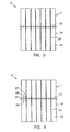
- the capillary electrophoresis system contains a capillary array 2 containing a plurality of coplanar parallel capillaries 1 , and the transparent portion 20 of the annular wall 3 extends around the capillaries 1 , and the capillaries 1 in the array 2 are substantially adjacent.
- An image array detector 21 having a linear array of pixels 22 located in a plane parallel to the capillary array 2 is optically coupled to the interior portions 23 of the capillaries 1 .
- the ratio of pixels 22 to capillaries 1 is 2:1, and the pixels 22 are positioned such that every second pixel in the linear array is optically coupled to a side wall 24 of a capillary 1 , and every pixel in between is coupled to an interior portion 23 of a capillary 1 .
- Figure 5 is an alternative view of the capillary arrays 2 shown in Figure 4 , showing a projection of the optically coupled pixels 22 onto the interior portions 23 and side walls 24, 25 of the substantially adjacent capillaries 1 .
- a group of pixels 26 having a leading pixel 27 , a middle group of pixels 28 , and a trailing pixel 29 , optically coupled to a capillary 1 .
- the leading pixel 27 is optically coupled to the first side wall 24 of a capillary 1
- the middle group of pixels 28 is optically coupled to an interior portion 23 of a capillary 1
- the trailing pixel 29 is optically coupled to a second side wall 25 of a capillary 1 .
- the middle group of pixels comprises two pixels as shown in Figure 6 ; most preferably, it comprises one pixel, as shown by implication in Figures 4 and 5 .
- the optically coupled pixels 26 are graphically projected onto the capillaries 1 in the array 2 for ease of illustration.
- Two pixels 28 are optically coupled to each capillary interior 23 .
- the pixels 27,29 optically coupled to a side wall 24,25 are shared by adjacent capillaries 1 .
- the ratio of optically coupled pixels to capillaries is less than about 6:1, preferably equal to about 3:1 and more preferably equal to about 2:1 for a capillary array of substantially adjacent coplanar capillaries.
- a 2:1 ratio is shown in Figures 4 and 5 ; a 3:1 ratio is shown in Figure 6 .
- the coplanar parallel capillaries may be arranged in an array comprising one or more subsets of substantially adjacent coplanar capillaries. In that event, the overall ratio of optically coupled pixels to capillaries for the entire array may be greater than 6:1, although for each subset of substantially adjacent coplanar capillaries the ratio is less than about 6:1.
- the ratio of optically coupled pixels to capillaries need not be an integer ratio.
- the number of pixels optically coupled to each capillary in the array may vary (see Figure 8 , described below). Likewise, if the capillaries in the array have variable diameters, the number of pixels optically coupled to each capillary in the array may vary.
- an imaging lens 26 is interposed between the capillary array 2 and the image array detector 21 used to optically couple the pixels 22 to the capillaries 1 .
- the alignment in Figure 7 shows a 2:1 ratio of pixels 22 to capillaries 1 , wherein every second pixel is optically coupled to a side wall 24 and every pixel in between is coupled to an interior portion 23 of a capillary 1 through the transparent portion 20 .
- the imaging lens 26 may be any lens capable of transforming an image onto the pixels of the image array detector, such as camera lens, for example a 24 mm wide-angle lens (Canon, Tokyo, Japan, Model FD 24 mm F1 .4L, 50 mm diameter) or a condenser lens.
- the image array detector may be a linear image array detector or a two-dimensional image array detector.
- it is a two-dimensional image array detector, more preferably a charge transfer device such as a charge-coupled device (CCD) or a charge-injection device (CID).
- CCD charge-coupled device
- CID charge-injection device
- the image array detector is a CID.
- the pixels optically coupled to a capillary may constitute a group of less than about six pixels, containing a leading pixel, a middle group of pixels, and a trailing pixel (see Figure 6 ).
- the leading pixel is optically coupled to a first side wall of a capillary
- the middle group of pixels is optically coupled to the interior portion of a capillary
- the trailing pixel is optically coupled to a second side wall of the capillary.
- the middle group contains two pixels. More preferably, it contains one pixel.
- the method may also include the additional step of selecting one pixel from the middle group of pixels and using that pixel to detect the fluorescence emission from the target species.
- more than one pixel is optically coupled to the interior of a capillary, it is desirable to select only one to analyze and to disregard the others, since the dark current increases with the number of pixels evaluated per capillary, thus increasing background noise.
- ideally only one pixel is optically coupled to each capillary (representing a 2:1 ratio of pixels to capillaries), obviating the need to make a pixel selection.
- the optically coupled pixels 23 are graphically projected onto the capillaries in the array for ease of illustration.
- a hatched pixel represents that pixel optically coupled to a given capillary which produces the greatest signal intensity when the capillary contains a fluorescing material as described below. Data from the hatched pixels is used for sample analysis.
- the method further includes a calibration step performed prior to introducing the sample.
- a fluorescing medium such as a fluorescein solution, preferably a solution containing about 10 -8 - 10 -5 M fluorescein, or a rhodamine solution, or any convenient fluorescing buffer, is introduced into a capillary. Fluoresence emission is induced from the fluorescing medium by irradiating the medium with a beam of coherent light having a wavelength of about 200-1500 nm, and is detected using the image array detector through the transparent portion of the annular wall.
- the fluorescence emission is detected by each member of the middle group of pixels optically coupled to the interior of the capillary.
- the intensity of the signal produced by each pixel in the middle group is compared, the pixel producing the signal with the greatest intensity is selected.
- the fluorescence emitted by a target species detected by the selected pixel is then used to perform data analysis.
- the most preferred image array detector is the charge-injection device.
- CID charge-transfer imaging device
- a CID is a solid-state charge-transfer imaging device (CTD) similar to a CCD, but it has characteristics not shared by CCDs that can be used to great advantage in multiplexed capillary electrophoresis. Where only a single capillary or a small number of capillaries is involved, there is no obvious advantage to using a CID because various photomultiplier tubes, avalanche photodiodes, or CCD cameras are available.
- CMOS image sensors when a large number of capillaries need to be monitored simultaneously in an array format, the unique features of a CID camera can make a significant difference. Those features include random pixel addressing, flexibility of user programmable architecture (particularly for programming exposure time), large dynamic range, low dark current, anti-blooming imaging, high tolerance to irradiation, high quantum yield over a wide wavelength range, and non-destructive readout.
- the "random access” or electronic-windowing function unique to CIDs is especially useful.
- the term “random access” refers to the special features of a CID that allow it to be calibrated or programmed to read only those pixels focused on a particular region of interest, saving enormous data analysis time and storage requirements compared to a CCD, which offers very little flexibility in the pixel readout.
- a CID can be calibrated to read only one or more pixels focused on a transparent portion of a capillary through which fluorescent emissions from a target species pass.
- the method further includes using random access programming to select a pixel having the greatest signal intensity from a group of pixels optically coupled to a capillary interior. The sample migration time for the target species is then determined by processing the signal produced by the selected pixel.
- the CID camera is operated at a pixel-read rate slower than a conventional CCD, it can achieve very high sampling rate with high exposure duty cycle and thus high sensitivity.
- the advantages are even greater when several spatially separated subarrays need to be read, as the space in between the subarrays need not be read in a CID.
- the CID can be further advantageously operated by programming it to utilize different exposure times to detect emissions of variable intensities. Shorter exposure time may be adequate for high intensity emissions, and longer exposure times can be used for lower intensity emissions. For example, a calibration run may be made in a DNA sequencing experiment to determine the approximate migration times of DNA fragments of various lengths. An exposure-time gradient can be then programmed to expose larger, longer running fragments having higher emission intensities for a shorter amount of time than needed for the faster, shorter fragments, thereby improving the signal to noise ratio for the larger DNA fragments while simultaneously reducing the volume of data generated. Thus, the method further includes using exposure time programming to vary the exposure time for a selected pixel during sample migration substantially inversely with the intensity of fluorescence emission from the target species.
- the exposure time programming is preferably effected by programming a time exposure gradient, which may be initially determined in a calibration run using DNA fragments of known size and fluorescence intensity, or by programming a feedback loop to automatically vary the exposure time with the fluorescence emission intensity detected by the selected pixel. Both random access programming and exposure time programming may be used.
- the CID can be operated using an asynchronous scanning mode.
- an asynchronous scanning mode the camera shutter is kept open and the subarray is scanned continuously without waiting between frame readouts to move to the next member of the array.
- the charge in each pixel is cleared individually during each frame without disturbing the other pixels.
- the duty cycle, frame rate, and charge-clearing time will vary as a function of the size of the subarray.
- the CID is operated at ambient temperature (20-30°). This makes it simpler and more compact to incorporate into an automated DNA sequencing instrument. Because there is no need for a liquid-N 2 dewar, the CID focal plane array occupies only a very small space.
- the present invention provides a capillary electrophoresis system to detect fluorescence emission from a fluorescent target species that utilizes only one excitation wavelength and that utilizes two long-pass filters, described below, to split the fluorescence emission into first and second emission channels.
- the first and second emission channels contain light having different wavelength ranges.
- a detector simultaneously detects the fluorescence emission in the first and second emission channels.
- the invention is especially well-suited for use in DNA sequencing and DNA diagnostics experiments where the target species are DNA fragments, and all four nucleotide bases are detected in a single capillary.
- a coherent light source 7 is positioned to direct a single beam of coherent light 8 so as to contact the interior portion 23 of at least one capillary 1 , which is defined by its annular wall 3 .
- a detector 34 is provided to detect fluorescence emission "E" from a fluorescent target species present in the capillary interior, which emission is split by the first 32 and second 33 long-pass filters into the first 30 and second 31 emission channels, respectively.
- the capillary is in fluid communication with a sample containing a fluorescent target species such that the sample is drawn into the capillary, where it is brought into contact with the beam of coherent light.
- Excitation of target species in a capillary may be effected in any convenient manner, such as through the wall of the capillary, as described below, or axially using fiber optics.
- the beam induces fluorescence emission from the target species.
- the annular wall of the capillary has a transparent portion through which fluorescence detection is effected.
- the system contains a capillary array of coplanar parallel capillaries, each capillary having a first transparent portion defining a transparent path extending through the capillary array perpendicular to the capillaries. The beam of coherent light is directed along the transparent path.
- Each annular wall has a second transparent portion for optically coupling the transparent path to a detector, as further described below.
- the long pass filters interposed between the target species and the detector are filters that transmit light having a wavelength longer than a stated value.
- a standard long pass filter with a stated wavelength value transmits about 50% of the light having the stated wavelength value, and decreasing percentages of light having shorter wavelengths, such that virtually no light having a wavelength shorter than about 50 nm below the stated value is transmitted.
- a Raman type long pass filter has an abrupt cutoff. Virtually no light having a wavelength shorter than the stated wavelength of a Raman long-pass filter is transmitted.
- the use of long-pass filters permits a much greater amount of light to reach the detector than can reach the detector when narrow band filters are used.
- Optimal excitation wavelengths and combinations of long-pass filters depend on the particular dyes used to label the DNA fragments in the sequencing reaction. In general, both filters screen out light having a wavelength at or below the wavelength used to excite the target DNA species.
- the first filter is selected to screen out stray laser light, i.e., light of a wavelength less than or about equal to the excitation wavelength, and the second filter is selected to screen out light of less than some higher wavelength, the cutoff value being dependent on the labels used to derivatize the DNA fragments.
- the first long-pass filter preferably has a wavelength cutoff value such that it transmits less than about 0.1%, more preferably 0.01%, of light having a wavelength about equal to the wavelength of the single beam of coherent light used to induce fluorescence from the target species, and the second long-pass filter preferably has a higher wavelength cutoff value. How much higher depends on the dye labels used and will be readily apparent to one of skill in the art. More preferably, the first long-pass filter is a Raman long-pass filter having a wavelength cutoff value about equal to the wavelength of the single beam of coherent light.
- the first filter is positioned immediately adjacent to the detector, and the second filter is positioned between the target DNA species and the first filter, such that it intercepts a portion of the emission that would otherwise have passed directly through the first filter, and such that it is tilted at an angle of about 1-89°, preferably about 20-40°, relative to the first filter.
- the light passing through the second filter subsequently passes through the first filter before contacting the array detector, and constitutes what may be referred to as the "red channel”.
- Light passing only through the first filter may correspondingly be referred to as the "blue channel", as it includes light having shorter wavelengths than that constituting the red channel.
- the amount of emission intercepted by the second filter can be adjusted to optimize the overall sensitivity of the two channels. Specifically, the ratios of the emissions detected by the two channels, which are used to determine the DNA sequence, are affected by the portion of the overall emission that is allocated to each channel by means of relative filter positioning.
- the second filter needs to be tilted to shift the image, via refraction, of the light passing through both filters, relative to that passing through only the first filter, to facilitate data analysis. It is particularly advantageous to use as the first filter a Raman long-pass filter which screens out wavelengths less than or about equal to the excitation wavelength and permits full throughput of higher wavelengths.
- a preferred detector is a two-dimensional image array detector, especially in multiplexed systems, although first and second linear detectors may also be employed, one for each channel. More preferably, a charge-coupled device (CCD) or a charge-injection device (CCD) is used.
- CCD charge-coupled device
- CCD charge-injection device
- rectangular filters with dimensions in excess of the array dimensions may be conveniently used to split fluorescence emissions simultaneously induced from target species in multiple capillaries in an array of coplanar parallel capillaries.
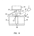
- a preferred embodiment of the system is shown in Figure 9 .
- a capillary 1 containing a fluorescent target species is placed on a mount 35 having a groove 36 .
- the groove reduces stray light interference by preventing the reflection of the excitation beam by the mount which would otherwise occur if the groove was not present.
- a coherent light source 7 is positioned to direct a single beam of coherent light 8' so as to induce fluorescence from the target species through the transparent portion 14' of the annular wall 3 of the capillary 1 .
- the fluorescence emission is split into a first channels, and a second channel 30 .
- the first channel 31 contains the fluorescence emission that passes through both the Raman long pass filter 32 and a standard long pass filter 33 .
- the Raman filter 32 is tilted at an angle of about 30° to the planar surface of the detector 34 in order to shift the image.
- the Raman filter 32 is positioned such that about half of the fluorescence emission from the target species contacts it.
- the second channel 30 contains that portion of the fluorescence emission that passes only through the standard long pass filter 33 . Both channels are detected by a CCD detector 34 .
- base calling a scheme for use in nucleotide identification in DNA sequencing, i.e., "base calling”, that is elegant and highly accurate, independent of concentration (incorporation rate for the polymerase), useful even for very poorly resolved peaks (potentially permitting extension of base calling to larger fragments and/or sacrificing some resolution for speed in the separation), requires minimal computation (improving speed and decreasing effort for data processing), and is compatible with the high light-throughput optics for excitation/emission described elsewhere herein.
- Fused-silica capillaries 45-60 cm long with 75 ⁇ m i.d., 150 ⁇ m or 360 ⁇ m o.d. (Polymicro Technologies, Inc., Phoenix, AZ) were used for separation.
- the inner wall of the capillary was coated with polyacrylamide or treated with 0.1 M HCl.
- the sieving matrix was prepared by dissolving 1.5% of 8,000,000 M n poly(ethyleneoxide) (PEO) and 1.4% of 600,000 M n PEO in running buffer, which was 1x TBE with 3.5 M urea.
- DNA sequencing samples were prepared from the Sanger reaction according to standard protocols (Applied Biosystems, Inc., Foster City, CA, DyeDeoxy Terminators and cycle sequencing with Taq polymerase) in the DNA Facility of Iowa State University. Capillaries were filled using a 5-ml syringe (Becton Dickinson & Co., Franklin Lakes, NJ) for 10-15 minutes by applying pressure at the syringe with a metal clamp. After a run was completed, the matrix was pushed out with compressed N 2 gas at 300 psi (15 x 10 3 torr) (within 2 minutes) or with a 100- ⁇ l syringe (Hamilton Company, Reno, NV) (within 30 seconds).
- N 2 gas 300 psi (15 x 10 3 torr) (within 2 minutes) or with a 100- ⁇ l syringe (Hamilton Company, Reno, NV) (within 30 seconds).
- the TEFLON tubing which was used to connect the capillary to the pressure devices was first filled with water so that the capillary would not become clogged by dried particles.
- Two 20-ml glass sample vials containing the running buffer were used as buffer reservoirs.
- the matrix-filled capillary was pre-run for 10 minutes before injection. Injection was at -9 kV to -12 kV for 20 seconds or 15 seconds, depending upon the length of the capillary. Electrophoresis was run by applying -9 kV to -15 kV at the injection end via a high-voltage power supply (Spellman, Plainview, NY).
- a capillary was mounted on an aluminum block of 1.6 cm (W) x 6.0 cm (L) x 6.5 cm (H). Two 0.3-cm wide, 3-cm deep grooves were cut across the width the mount to form two optical channels. The deep grooves helped to reduce background noise from scattered light. The two channels were placed 0.9 cm apart to reduce interference of scattered light between the two detection channels when the two-wavelength, two-beam excitation scheme was employed.
- the capillary was placed flat on the mount across the grooves and taped tight to it (Scotch tape, 3M, St. Paul, MN).
- the CID camera was set up above the capillary mount so that the capillary was oriented along the CID imager columns. The mount was wide enough to accommodate as many as 100 capillaries with 150 ⁇ m o.d.
- An air-cooled Ar + laser (Uniphase, San Jose, CA, Model 2213-150ML) with multi-line emission was used for excitation.
- the 488-nm and 514-nm lines were separated with a glass prism.
- two 0.5-cm detection windows 1.2 cm apart were formed on the capillary by burning off the coating with boiling sulfuric acid.
- the detection windows were placed at the detection channels aligned with the grooves on the aluminum mount.
- the 488-nm beam and 514-nm beam were focused with 10-cm focal length lenses (Oriel, Stratford, CT) from the same side of the capillary mount.
- the edges of the two lenses were trimmed off to allow placing them side by side with the centers of the lenses in the light paths.
- the laser beams were perpendicular to the capillary and the CID camera.
- a 5 cm x 8 cm x 2 mm quartz plate was placed 4 mm horizontally above the capillary.
- a 600-nm high precision interference long pass filter (Ealing Electro-optics, South Natick, MA) and a RG610 glass filter (Schott Glass, Duryea, PA) was placed on top of the 514-nm excitation channel.
- a 0.5-inch diameter 488-nm Raman-edge filter (Physical Optics, Torrance, CA) was placed on top of the 488-nm excitation channel.
- the 488-nm beam was split into two with a beam splitter (Melles Griot, Irvine, CA) to illuminate both detection windows.
- Beam focusing and filter setting were the same as that in the two-wavelength, two-beam excitation scheme.
- a 5 cm x 5 cm x 3 mm RG610 filter (Schott Glass) was tilted at 30° relative to the focal plane of the camera. With the top edge of the RG610 filter parallel to the laser beam and facing toward the center of the field of view, the filter was translated until the top edge of the filter passed about 0.5 cm beyond the detection window. Light originating from the half of the field of view which was covered by the filter (red channel) was thus shifted toward the side of the filter. Emission was thus focused as one image which was 9 CID imager rows away from the original image. Light originating from the other half of the field of view (blue channel) was focused as before. The distance between the two images can be changed by adjusting the tilt angle of the RG610 filter.
- the RG610 filter served the dual purposes of image displacer and optical filter.
- the RG610 filter also blocked the strongest scattered laser light, which forms a fan perpendicular to the capillary array. This is very important in reducing scattered light background at the blue channel.
- the scattered laser light hitting the RG610 filter produced some fluorescence, the fluorescing part of the RG610 filter was out of focus and did not cause significant background in the image area in the CID detector.
- the difference in effective optical pathlengths for the light in the two halves of the field of view can be compensated with a quartz plate.
- the quartz plate can be tilted at the same angle as the RG610 filter and covers the other half of the field of view in the same way as the RG610 filter.
- Peak-height ratios The spectral properties of the four standard dye labels (FAM, JOE, ROX and TAMRA, ABD Division of Perkin Elmer, Foster City, CA) for the Sanger reaction were distinguished with a peak-height ratio coding method when two long-pass filters were used for the two spectral channels. For one capillary, two electropherograms were generated, each corresponding to one spectral channel. Integration results from standard chromatographic software were saved in ASCII files. Only migration times and peak heights were imported into a worksheet for base calling. Migration time was used as the index to match the peaks of the same base at the two spectral channels.
- the Raman-edge filter let through more light (which is always desirable) and discriminated better between adenosine (A) and guanine (G) DNA fragments compared to a 515-nm long-pass cutoff filter.
- a 610-nm long-pass cutoff filter discriminated better between cytosine (C) and (T) DNA fragments compared to a 600-nm filter and was chosen even though the latter let through more light.
- the best combination turned out to be the 488-nm Raman-edge (RE) filter and RG610 filter. Both filters allowed all bases to be detected at both spectral channels. The peak-height ratio was thus calculated for all bases.
- the major advantage of using long-pass filters is that optical throughput is maximized. This is important because the detection limit determines how far one can read the bases in a given sequencing run.
- a histogram was built from the peak-height ratios.
- the criteria to call bases i.e., determine the nucleotides represented by the DNA fragments produced in a DNA sequencing experiment
- only the peaks within good separation resolution range were used in the calibration step. Peaks within 250 bp length met this requirement.
- the peaks fell into four distinct clusters ( Figure 11 ). Dashed lines were demarcation points for nucleotide base identification (base calling).
- the excitation wavelength used was 488-nm, and fluorescence emission was detected using 610-nm vs. 515-nm long-pass filters.
- Three ratios were determined from the locations of the gaps between the four clusters, namely R 1 , R 2 , R 3 .
- a formula was set in the spreadsheet to call all the bases automatically with G ⁇ R 1 , R 1 ⁇ A ⁇ R 2 , R 2 ⁇ T ⁇ R 3 , and R 3 ⁇ C. Standard deviations of the peak-height ratios were calculated for all of the same kind of bases within the readable base-pair range.
- the boundaries of the four clusters, i.e., R 1 , R 2 , R 3 were thus defined with certainty at least as high as 99.7% ( ⁇ 3 ⁇ ).
- the base calling criteria which is simply the R 1 , R 2 , R 3 values, will not change.
- a series of unknown DNA samples can then, be sequenced in the calibrated system up to the readable length.
- base calling was based upon differences in fluorescence spectra as well as in absorption spectra. It also provided better S/N for the 2 rhodamine labels (FAM and JOE). DNA fragments were excited twice as they passed through the two detection windows. However, scattered 514-nm light introduced extra background at the 488-nm channel where the RE filter was used because the RE filter did not block 514-nm light. Careful alignment and proper setup was necessary in order to minimize the interference. It was necessary to physically isolate the two channels by placing a shield between them. The physical isolation was especially important when the capillary array was immersed in refractive-index matching liquid because Rayleigh and Raman scattering is much stronger in liquid than in air.
- Scattered laser light not only distributed around the outside of the capillary, but also propagated within the capillary by internal reflection due to the differences of refractive index among the matrix, the capillary wall and air. It was found to be beneficial to leave several millimeters of polyimide coating between the two detection windows.
- the coating absorbed scattered laser light that propagated from one detection channel along the capillary to the other detection channel.
- Matching of the migration times by normalization to the relative distance traveled depends on having uniform velocities (temperature, matrix homogeneity) along the entire capillary.
- the two laser beams also produced scattered light that can interfere with each other (514 nm laser line transmitted by the Raman-edge filter) and decrease the S/N. So, the 488 nm laser line was used alone. All four standard dye labels absorb at 488 nm, although not all four do so equally efficiently.
- the two-window approach was retained but the output from one laser was split to favor the red channel (passing through the 610 nm filter) in order to compensate for the lower absorption of those 2 dye labels.
- the results were essentially the same as those obtained by using 2 wavelengths in excitation. The advantages were lower stray light (no 514 nm present) and simplicity in using a single-line laser. Matching the migration times from the two channels was still necessary, however.
- the one-beam excitation scheme provided the freedom of operating the system at any gradient mode necessary to enhance resolution or detectability, such as by using exposure-time gradient, temperature gradient and voltage gradient, or combinations of these gradient methods.
- Ratiograms The base calling procedure based on the one excitation laser/two emission wavelength data described above was subsequently further improved. Instead of relying on software to identify peaks and determine peak heights at each channel, a "ratiogram" was generated, which is the ratio of signals from the two channels calculated point by point at each data interval. Similar ratiograms have been used in liquid chromatography to determine peak purity when using diode array detectors or rapid-scan multiwavelength detectors. Software is in fact included in several commercial instruments. The idea is that the ratio of intensities at two independent wavelengths is independent of concentration (which varies across the peak), and can be used to sort out the unresolved components in the merged peaks.
- Figure 10 shows a ratiogram plotted on top of the electropherogram obtained through the RE filter, which records all peaks regardless of the label.
- the horizontal lines are artifacts to prevent division errors when S/N is too low to determine a meaningful ratio.
- the raw signal from the 488 nm excitation/Raman edge filter is plotted below (light line).
- the called bases are typed on the abscissa. The accuracy was 99% through 340 bases.
- the ratiogram clearly shows that the leading edge was "A" and the trailing edge was "G" in character. So, even though this feature led to base calling error in the peak-height scheme using chromatography software, it was correctly called in this novel scheme.
- Other noteworthy portions are the regions around markers 600 and 1180, where partially resolved features were correctly called in a similar fashion.
Claims (18)
- Multiplex-Kapillarelektrophoresesystem, aufweisend:ein Kapillarenfeld (2) koplanarer paralleler Kapillaren (1), die jeweils einen Innenbereich (23) zur Anordnung einer Objektsorte und eine den Innenbereich (23) umschreibende ringförmige Wand (3) aufweisen,eine kohärente Lichtquelle (7), die angeordnet ist, einen Strahl (8) kohärenten Lichts so zu leiten, dass aus der Objektsorte Fluoreszenzemission hervorgerufen wird, undeinen Detektor (34), der zum Erfassen der Fluoreszenzemission angeordnet ist,wobei jede Kapillare (1) einen ersten transparenten Abschnitt (4) ihrer ringförmigen Wand (3) aufweist, wodurch ein durch das Kapillarenfeld (2) senkrecht zu den Kapillaren (1) verlaufender transparenter Pfad (5) festgelegt ist, entlang dem der Strahl (8) durch den Innenbereich jeder Kapillare (1) geleitet wird,
gekennzeichnet durch ein erstes und ein zweites Langwegfilter (32, 33), die angeordnet sind, die Fluoreszenzemission entsprechenderweise in einen ersten und einen zweiten Emissionskanal (30, 31) zum gleichzeitigen Erfassen vom Detektor (34) aufzuspalten. - System nach Anspruch 1, wobei der erste transparente Abschnitt (4) um die Kapillare (1) herum verläuft.
- System nach Anspruch 1, wobei der transparente Pfad (5) eine durch die Kapillaren (1) verlaufende Ebene umfasst.
- System nach Anspruch 1, wobei der erste transparente Abschnitt (4) gegenüber Licht mit einer Wellenlänge ungefähr gleich der Wellenlänge des Strahls (8) kohärenten Lichts transparent ist.
- System nach Anspruch 1, wobei die parallelen Kapillaren (1) im Wesentlichen aneinander angrenzen.
- System nach Anspruch 1, wobei zwischen der kohärenten Lichtquelle (7) und dem Kapillarenfeld (2) eine kollimierende Fokuslinse (9) angeordnet ist.
- System nach Anspruch 1, wobei der Strahl (8) kohärenten Lichts in den Kapillaren (1) einen geringeren Durchmesser als etwa 300 Mikrometer aufweist.
- System nach Anspruch 7, wobei der Strahl (8) kohärenten Lichts in den Kapillaren (1) einen geringeren Durchmesser als etwa 75 Mikrometer aufweist.
- System nach Anspruch 1, wobei die kohärente Lichtquelle (7) einen Laser mit einer Leistungsabgabe von etwa 0,5 bis 50 mW aufweist.
- System nach Anspruch 1, wobei die ringförmige Wand (3) jeweils einen zweiten transparenten Abschnitt (4, 14) zum optischen Koppeln des transparenten Pfads (5) an einen Ort außerhalb des Kapillarenfelds (2) aufweist.
- System nach Anspruch 10, wobei der Ort außerhalb des Kapillarenfelds (2) eine ebene Fläche parallel zum Kapillarenfeld (2) umfasst.
- System nach Anspruch 10, wobei der zweite transparente Abschnitt (4, 14) der jeweiligen ringförmigen Wand (3) mit dem ersten transparenten Abschnitt (4) der ringförmigen Wand (3) zusammenhängt.
- System nach Anspruch 10, wobei der Ort außerhalb des Kapillarenfelds (2) einen optischen Detektor (16) aufweist.
- System nach Anspruch 13, wobei zumindest eine Kapillare (1) für Fluid in Verbindung mit einer eine fluoreszente Objektsorte enthaltenden Probe (6) steht, so dass die Probe in die Kapillare (1) gezogen wird, und wobei der optische Detektor (16) die Fluoreszenzemission der Objektsorte erfassen kann.
- System nach Anspruch 1, wobei die kohärente Lichtquelle (7) angeordnet ist, einen Strahl (8) kohärenten Lichts mit einer Wellenlänge von etwa 200 bis 1500 nm so abzugeben, dass er den Innenbereich (23) jeder Kapillare (1) berührt und Fluoreszenzemission aus der Objektsorte bewirkt.
- System nach Anspruch 15 mit einem ersten und einem zweiten Langwegfilter (33, 32), die so angeordnet sind, dass sie die Fluoreszenzemission in einen ersten und einen zweiten Emissionskanal (30, 31) aufspalten, sowie einem Detektor (34) zum gleichzeitigen Erfassen der Fluoreszenzemission im ersten und zweiten Emissionskanal (30, 31).
- System nach Anspruch 16, wobei das erste Langwegfilter (33) zwischen dem Detektor (34) und dem transparenten Abschnitt (4) einer ringförmigen Wand (3) so angeordnet ist, dass die Fluoreszenzemission durch das erste Langwegfilter (33) hindurchtritt, und das zweite Langwegfilter (32) zwischen dem ersten Langwegfilter (33) und dem transparenten Abschnitt (4) der ringförmigen Wand (3) unter einem Winkel von etwa 1 Grad bis 89 Grad gegenüber dem ersten Langwegfilter (33) so angeordnet ist, dass ein Teil der Fluoreszenzemission durch das zweite Langwegfilter (32) hindurchtritt, bevor er durch das erste Langwegfilter (33) hindurchtritt.
- System nach Anspruch 16, wobei das zweite Langwegfilter (32) zwischen dem Detektor (34) und dem transparenten Abschnitt (4) einer ringförmigen Wand (3) so angeordnet ist, dass die Fluoreszenzemission durch das zweite Langwegfilter (32) hindurchtritt, und das erste Langwegfilter (33) zwischen dem zweiten Langwegfilter (32) und dem transparenten Abschnitt (4) der ringförmigen Wand (3) unter einem Winkel von zwischen etwa 1 Grad und 89 Grad gegenüber dem zweiten Langwegfilter (32) so angeordnet ist, dass ein Teil der Fluoreszenzemission durch das erste Langwegfilter (33) hindurchtritt, bevor er durch das zweite Langwegfilter (32) hindurchtritt.
Applications Claiming Priority (3)
| Application Number | Priority Date | Filing Date | Title |
|---|---|---|---|
| US08/444,565 US5582705A (en) | 1995-05-19 | 1995-05-19 | Multiplexed capillary electrophoresis system |
| EP96921215A EP0830593B1 (de) | 1995-05-19 | 1996-05-16 | Vorrichtung für Kapillarelektrophorese |
| EP01200771A EP1109014B1 (de) | 1995-05-19 | 1996-05-16 | Multiplexvorrichtung für Kapillarelektroforese |
Related Parent Applications (1)
| Application Number | Title | Priority Date | Filing Date |
|---|---|---|---|
| EP01200771A Division EP1109014B1 (de) | 1995-05-19 | 1996-05-16 | Multiplexvorrichtung für Kapillarelektroforese |
Publications (2)
| Publication Number | Publication Date |
|---|---|
| EP1835281A1 EP1835281A1 (de) | 2007-09-19 |
| EP1835281B1 true EP1835281B1 (de) | 2009-09-02 |
Family
ID=23765448
Family Applications (7)
| Application Number | Title | Priority Date | Filing Date |
|---|---|---|---|
| EP06006746A Withdrawn EP1669752A1 (de) | 1995-05-19 | 1996-05-16 | Verfahren zur Vorbereitung einer Kapillare for die Kapillarelektrophorese |
| EP01200771A Expired - Lifetime EP1109014B1 (de) | 1995-05-19 | 1996-05-16 | Multiplexvorrichtung für Kapillarelektroforese |
| EP07075526A Expired - Lifetime EP1835281B1 (de) | 1995-05-19 | 1996-05-16 | Multiplexvorrichtung für Kapillarelektrophorese |
| EP07075527A Expired - Lifetime EP1837647B1 (de) | 1995-05-19 | 1996-05-16 | Multiplexvorrichtung für Kapillarelektrophorese |
| EP10000073.6A Expired - Lifetime EP2199784B1 (de) | 1995-05-19 | 1996-05-16 | Multiplexvorrichtung für Kapillarelektrophorese |
| EP96921215A Expired - Lifetime EP0830593B1 (de) | 1995-05-19 | 1996-05-16 | Vorrichtung für Kapillarelektrophorese |
| EP06077079A Expired - Lifetime EP1760462B1 (de) | 1995-05-19 | 1996-05-16 | Verfahren zur Vorbereitung einer unbeschichteten Quarzglas-Kapillare für Kapillarelektrophorese |
Family Applications Before (2)
| Application Number | Title | Priority Date | Filing Date |
|---|---|---|---|
| EP06006746A Withdrawn EP1669752A1 (de) | 1995-05-19 | 1996-05-16 | Verfahren zur Vorbereitung einer Kapillare for die Kapillarelektrophorese |
| EP01200771A Expired - Lifetime EP1109014B1 (de) | 1995-05-19 | 1996-05-16 | Multiplexvorrichtung für Kapillarelektroforese |
Family Applications After (4)
| Application Number | Title | Priority Date | Filing Date |
|---|---|---|---|
| EP07075527A Expired - Lifetime EP1837647B1 (de) | 1995-05-19 | 1996-05-16 | Multiplexvorrichtung für Kapillarelektrophorese |
| EP10000073.6A Expired - Lifetime EP2199784B1 (de) | 1995-05-19 | 1996-05-16 | Multiplexvorrichtung für Kapillarelektrophorese |
| EP96921215A Expired - Lifetime EP0830593B1 (de) | 1995-05-19 | 1996-05-16 | Vorrichtung für Kapillarelektrophorese |
| EP06077079A Expired - Lifetime EP1760462B1 (de) | 1995-05-19 | 1996-05-16 | Verfahren zur Vorbereitung einer unbeschichteten Quarzglas-Kapillare für Kapillarelektrophorese |
Country Status (4)
| Country | Link |
|---|---|
| US (3) | US5582705A (de) |
| EP (7) | EP1669752A1 (de) |
| DE (5) | DE69638110D1 (de) |
| WO (1) | WO1996036872A1 (de) |
Families Citing this family (209)
| Publication number | Priority date | Publication date | Assignee | Title |
|---|---|---|---|---|
| US6156177A (en) * | 1991-02-28 | 2000-12-05 | Hitachi, Ltd. | DNA detector and DNA detection method |
| US5529679A (en) * | 1992-02-28 | 1996-06-25 | Hitachi, Ltd. | DNA detector and DNA detection method |
| US5833827A (en) * | 1995-09-29 | 1998-11-10 | Hitachi, Ltd. | Capillary array electrophoresis system |
| DE69634696T2 (de) * | 1995-10-06 | 2006-01-19 | PerSeptive Biosystems, Inc., Framingham | Verfahren und testsystem zur hybridisierungsanalyse unter verwendung von peptidnukleinsäure-sonden |
| US20010041333A1 (en) * | 1997-06-16 | 2001-11-15 | Short Jay M. | High throughput screening for a bioactivity or biomolecule |
| US6794127B1 (en) * | 1997-06-16 | 2004-09-21 | Diversa Corporation | Capillary array-based sample screening |
| US6972183B1 (en) | 1997-06-16 | 2005-12-06 | Diversa Corporation | Capillary array-based enzyme screening |
| US20020048809A1 (en) * | 1997-06-16 | 2002-04-25 | Lafferty William Micharl | Capillary array-based sample screening |
| US7157724B2 (en) * | 1996-02-08 | 2007-01-02 | Bright Solutions, Inc. | Detection lamp |
| US7253557B2 (en) * | 1996-02-08 | 2007-08-07 | Bright Solutions, Inc. | Light source provided with a housing enclosing voltage regulator means and method of manufacturing thereof |
| US5867266A (en) * | 1996-04-17 | 1999-02-02 | Cornell Research Foundation, Inc. | Multiple optical channels for chemical analysis |
| JP3559648B2 (ja) * | 1996-04-23 | 2004-09-02 | 株式会社日立製作所 | キャピラリーアレー電気泳動装置 |
| US6043036A (en) * | 1996-04-23 | 2000-03-28 | Aclara Biosciences | Method of sequencing nucleic acids by shift registering |
| JP3467995B2 (ja) * | 1996-11-28 | 2003-11-17 | 株式会社日立製作所 | キャピラリー電気泳動装置 |
| US5750596A (en) * | 1996-12-23 | 1998-05-12 | E. I. Du Pont De Nemours And Company | Cathodic electrocoating compositions containing an anticrater agent |
| EP0854362A3 (de) * | 1997-01-16 | 2000-12-20 | Japan Science and Technology Corporation | Mehrkapillarelektroforesevorrichtung |
| US5851370A (en) * | 1997-01-24 | 1998-12-22 | Motorola Corporation | Automated electrophoresis system and method |
| JPH10227740A (ja) | 1997-02-18 | 1998-08-25 | Hitachi Ltd | 多色蛍光検出電気泳動分析装置 |
| US6084667A (en) * | 1997-03-12 | 2000-07-04 | Nz Applied Technologies | System and method for molecular sample measurement |
| US5903348A (en) * | 1997-03-12 | 1999-05-11 | Nz Applied Technologies, Inc. | System and method for molecular sample measurements |
| US6445448B1 (en) | 1997-03-12 | 2002-09-03 | Corning Applied Technologies, Corp. | System and method for molecular sample measurement |
| US20020015997A1 (en) * | 1997-06-16 | 2002-02-07 | Lafferty William Michael | Capillary array-based sample screening |
| US20050070005A1 (en) * | 1997-06-16 | 2005-03-31 | Martin Keller | High throughput or capillary-based screening for a bioactivity or biomolecule |
| US20030013115A1 (en) * | 1997-06-16 | 2003-01-16 | Diversa Corporation, A Delaware Corporation | Capillary array-based sample screening |
| US20040241759A1 (en) * | 1997-06-16 | 2004-12-02 | Eileen Tozer | High throughput screening of libraries |
| US6027627A (en) * | 1997-06-30 | 2000-02-22 | Spectrumedix Corporation | Automated parallel capillary electrophoretic system |
| US6493459B2 (en) * | 1997-11-06 | 2002-12-10 | Fuji Photo Film Co., Ltd. | Image reading apparatus |
| US6054032A (en) * | 1998-01-27 | 2000-04-25 | 3M Innovative Properties Company | Capillary electrophoresis array |
| FR2774472B1 (fr) * | 1998-01-30 | 2000-04-21 | Centre Nat Rech Scient | Perfectionnements aux systemes d'electrophorese multicapillaire |
| DE19803753C1 (de) * | 1998-01-30 | 1999-12-02 | Max Planck Gesellschaft | Vorrichtung und Verfahren zur Kapillarelektrophorese |
| WO1999041599A1 (fr) * | 1998-02-16 | 1999-08-19 | The Institute Of Physical And Chemical Research | Cassette capillaire et procede de production correspondant |
| US6103083A (en) * | 1998-02-20 | 2000-08-15 | Tetragen | Capillary electrophoresis apparatus and method |
| US6475361B1 (en) | 1998-02-20 | 2002-11-05 | Tetragen Sa | Capillary electrophoresis apparatus having filling/refilling system and methods for use thereof |
| CA2328881A1 (en) * | 1998-04-16 | 1999-10-21 | Northeastern University | Expert system for analysis of dna sequencing electropherograms |
| JP2003524754A (ja) | 1998-05-16 | 2003-08-19 | ピーイー コーポレイション (エヌワイ) | Dnaのポリメラーゼ連鎖反応をモニタする装置 |
| US6818437B1 (en) | 1998-05-16 | 2004-11-16 | Applera Corporation | Instrument for monitoring polymerase chain reaction of DNA |
| US7498164B2 (en) | 1998-05-16 | 2009-03-03 | Applied Biosystems, Llc | Instrument for monitoring nucleic acid sequence amplification reaction |
| SE9802558D0 (sv) | 1998-07-16 | 1998-07-16 | Hanning Instr Ab | Device for detection of fluorescent |
| WO2000005435A2 (en) * | 1998-07-24 | 2000-02-03 | Ce Resources Pte Ltd. | Array electrophoretic apparatus |
| AU5311699A (en) * | 1998-07-28 | 2000-02-21 | Ce Resources Pte Ltd | Optical detection system |
| US6464850B1 (en) | 1998-07-31 | 2002-10-15 | Biowhittaker Molecular Applications, Inc. | Method for producing hydrophilic monomers and uses thereof |
| WO2000013018A2 (de) * | 1998-08-28 | 2000-03-09 | Febit Ferrarius Biotechnology Gmbh | Träger für analytbestimmungsverfahren und verfahren zur herstellung des trägers |
| US6387234B1 (en) | 1998-08-31 | 2002-05-14 | Iowa State University Research Foundation, Inc. | Integrated multiplexed capillary electrophoresis system |
| US6821402B1 (en) * | 1998-09-16 | 2004-11-23 | Applera Corporation | Spectral calibration of fluorescent polynucleotide separation apparatus |
| EP1006355A3 (de) | 1998-11-30 | 2000-11-08 | The Institute of Physical and Chemical Research | Kapillarelektrophoresegerät |
| US6464852B1 (en) * | 1998-12-03 | 2002-10-15 | State University Of New York At Stony Brook | Multicapillary bundle for electrophoresis and detection for DNA |
| US6246046B1 (en) | 1999-01-21 | 2001-06-12 | University Of Pittsburgh | Method and apparatus for electronically controlled scanning of micro-area devices |
| US6558945B1 (en) * | 1999-03-08 | 2003-05-06 | Aclara Biosciences, Inc. | Method and device for rapid color detection |
| US6937330B2 (en) | 1999-04-23 | 2005-08-30 | Ppd Biomarker Discovery Sciences, Llc | Disposable optical cuvette cartridge with low fluorescence material |
| JP4175735B2 (ja) * | 1999-05-12 | 2008-11-05 | 独立行政法人理化学研究所 | マルチキャピラリー電気泳動装置 |
| JP4159702B2 (ja) * | 1999-05-12 | 2008-10-01 | 独立行政法人理化学研究所 | キャピラリーカラムへのゲル充填装置 |
| US6355921B1 (en) | 1999-05-17 | 2002-03-12 | Agilent Technologies, Inc. | Large dynamic range light detection |
| CA2379836A1 (en) * | 1999-07-21 | 2001-02-01 | Aaron B. Kantor | System for microvolume laser scanning cytometry |
| US6687395B1 (en) * | 1999-07-21 | 2004-02-03 | Surromed, Inc. | System for microvolume laser scanning cytometry |
| US6352633B1 (en) * | 1999-08-31 | 2002-03-05 | Spectrumedix Corporation | Automated parallel capillary electrophoresis system with hydrodynamic sample injection |
| AU6382800A (en) * | 1999-09-09 | 2001-04-10 | Iowa State University Research Foundation Inc. | Method of analyzing multiple samples simultaneously by detecting absorption and systems for use in such a method |
| US6788414B1 (en) | 1999-09-09 | 2004-09-07 | Iowa State University Research Foundation, Inc. | Method of analyzing multiple sample simultaneously by detecting absorption and systems for use in such a method |
| US6906797B1 (en) * | 1999-09-13 | 2005-06-14 | Aclara Biosciences, Inc. | Side light activated microfluid channels |
| US6379889B1 (en) | 1999-11-04 | 2002-04-30 | Agilent Technologies, Inc. | Multiplexing methods for identifying nucleic acids using denaturing liquid chromatography |
| US6406604B1 (en) * | 1999-11-08 | 2002-06-18 | Norberto A. Guzman | Multi-dimensional electrophoresis apparatus |
| US7329388B2 (en) * | 1999-11-08 | 2008-02-12 | Princeton Biochemicals, Inc. | Electrophoresis apparatus having staggered passage configuration |
| US6592733B1 (en) | 1999-11-12 | 2003-07-15 | Motorola, Inc. | Capillary electrophoresis devices incorporating optical waveguides |
| US6596483B1 (en) * | 1999-11-12 | 2003-07-22 | Motorola, Inc. | System and method for detecting molecules using an active pixel sensor |
| US20020028160A1 (en) * | 2000-02-22 | 2002-03-07 | Jianming Xiao | Method and apparatus based on bundled capillaries for high throughput screening |
| WO2001077386A2 (en) * | 2000-04-05 | 2001-10-18 | Iowa State University Research Foundation, Inc. | High-throughput detection of unknown dna mutations by using multiplexed capillary electrophoresis |
| JP3876714B2 (ja) * | 2000-04-12 | 2007-02-07 | 株式会社日立製作所 | キャピラリーアレイユニット及びそれを用いた電気泳動装置 |
| CA2407124C (en) * | 2000-04-25 | 2010-09-28 | Spectrumedix Corporation | Denaturant-free electrophoresis of biological molecules under high temperature conditions |
| US6690467B1 (en) * | 2000-05-05 | 2004-02-10 | Pe Corporation | Optical system and method for optically analyzing light from a sample |
| JP3893849B2 (ja) * | 2000-05-15 | 2007-03-14 | 株式会社日立製作所 | キャピラリアレイ電気泳動装置及び電気泳動方法 |
| JP4103302B2 (ja) * | 2000-05-15 | 2008-06-18 | 株式会社日立製作所 | キャピラリアレイを用いた電気泳動装置及びそれに用いられるサンプルプレートアセンブリ |
| JP3918403B2 (ja) * | 2000-05-15 | 2007-05-23 | 株式会社日立製作所 | キャピラリアレイ |
| US6805784B2 (en) | 2000-05-15 | 2004-10-19 | Hitachi, Ltd. | Capillary array |
| JP4003374B2 (ja) * | 2000-05-15 | 2007-11-07 | 株式会社日立製作所 | キャピラリアレイ電気泳動装置及び試料の分離・分析方法 |
| US6547943B1 (en) * | 2000-05-25 | 2003-04-15 | Spectrumedix Llc | Capillary system providing multiple analysis of sample from same body of liquid |
| US6544396B1 (en) | 2000-07-20 | 2003-04-08 | Symyx Technologies, Inc. | Multiplexed capillary electrophoresis system |
| US6531041B1 (en) | 2000-07-20 | 2003-03-11 | Symyx Technologies, Inc. | Multiplexed capillary electrophoresis system with rotatable photodetector |
| US6462816B1 (en) | 2000-07-21 | 2002-10-08 | Symyx Technologies, Inc. | Parallel capillary electrophoresis system having signal averaging and noise cancellation |
| US6572750B1 (en) * | 2000-07-21 | 2003-06-03 | Symyx Technologies, Inc. | Hydrodynamic injector |
| JP3882484B2 (ja) | 2000-08-25 | 2007-02-14 | 株式会社日立製作所 | 電気泳動方法,電気泳動装置及びキャピラリアレイ |
| US6706162B1 (en) | 2000-09-25 | 2004-03-16 | Applera Corporation | High speed, high resolution compositions, methods, and kits for capillary electrophoresis |
| DE10051396A1 (de) * | 2000-10-17 | 2002-04-18 | Febit Ferrarius Biotech Gmbh | Verfahren und Vorrichtung zur integrierten Synthese und Analytbestimmung an einem Träger |
| JP2002131281A (ja) * | 2000-10-27 | 2002-05-09 | Nippon Sheet Glass Co Ltd | Dna分析用ガラスキャピラリアレイ及びその製造方法 |
| US6787761B2 (en) * | 2000-11-27 | 2004-09-07 | Surromed, Inc. | Median filter for liquid chromatography-mass spectrometry data |
| US20020095260A1 (en) * | 2000-11-28 | 2002-07-18 | Surromed, Inc. | Methods for efficiently mining broad data sets for biological markers |
| US6800438B2 (en) * | 2000-12-28 | 2004-10-05 | Xerox Corporation | Imager for DNA sequencer |
| US7309409B2 (en) * | 2001-01-26 | 2007-12-18 | Biocal Technology, Inc. | Multi-channel bio-separation cartridge |
| WO2002059592A2 (en) | 2001-01-26 | 2002-08-01 | Biocal Technology, Inc. | Optical detection in a multi-channel bio-separation system |
| US6878254B2 (en) * | 2001-03-02 | 2005-04-12 | Iowa State University Research Foundation, Inc. | Size separation of analytes using monomeric surfactants |
| US6944322B2 (en) | 2001-03-28 | 2005-09-13 | Visiongate, Inc. | Optical tomography of small objects using parallel ray illumination and post-specimen optical magnification |
| US20060023219A1 (en) * | 2001-03-28 | 2006-02-02 | Meyer Michael G | Optical tomography of small objects using parallel ray illumination and post-specimen optical magnification |
| US7907765B2 (en) | 2001-03-28 | 2011-03-15 | University Of Washington | Focal plane tracking for optical microtomography |
| US6591003B2 (en) * | 2001-03-28 | 2003-07-08 | Visiongate, Inc. | Optical tomography of small moving objects using time delay and integration imaging |
| JP3897277B2 (ja) * | 2001-04-02 | 2007-03-22 | 株式会社日立製作所 | キャピラリアレイ及びキャピラリアレイ光検出装置 |
| US6839564B2 (en) * | 2001-04-25 | 2005-01-04 | Nokia Corporation | Synchronization of database data |
| US20020160427A1 (en) * | 2001-04-27 | 2002-10-31 | Febit Ag | Methods and apparatuses for electronic determination of analytes |
| US6731437B2 (en) * | 2001-05-04 | 2004-05-04 | Applera Corporation | Energy beam guide for an electrophoresis system |
| US6932940B2 (en) * | 2001-06-22 | 2005-08-23 | Biocal Technology, Inc. | Optical detection in bio-separation device using axial radiation input |
| US6929779B2 (en) | 2001-06-22 | 2005-08-16 | Biocal Technology, Inc. | Optical detection in bio-separation device using axial radiation output |
| US7280207B2 (en) * | 2001-07-25 | 2007-10-09 | Applera Corporation | Time-delay integration in a flow cytometry system |
| US7265833B2 (en) * | 2001-07-25 | 2007-09-04 | Applera Corporation | Electrophoretic system with multi-notch filter and laser excitation source |
| EP1412724B1 (de) | 2001-07-25 | 2016-03-23 | Life Technologies Corporation | Zeitverzögerungintegration in elektrophoretischen nachweissystemen |
| US6741730B2 (en) | 2001-08-10 | 2004-05-25 | Visiongate, Inc. | Method and apparatus for three-dimensional imaging in the fourier domain |
| US6873915B2 (en) * | 2001-08-24 | 2005-03-29 | Surromed, Inc. | Peak selection in multidimensional data |
| US20080288178A1 (en) * | 2001-08-24 | 2008-11-20 | Applera Corporation | Sequencing system with memory |
| US6627433B2 (en) * | 2001-08-24 | 2003-09-30 | Applera Corporation | Multi-channel analyte-separation device employing side-entry excitation |
| US7019831B2 (en) * | 2001-08-24 | 2006-03-28 | Applera Corporation | Separation device substrate including non-fluorescent quencher dye |
| JP4316170B2 (ja) * | 2001-09-05 | 2009-08-19 | 富士フイルム株式会社 | 画像データ作成方法および装置 |
| US6744502B2 (en) * | 2001-09-28 | 2004-06-01 | Pe Corporation (Ny) | Shaped illumination geometry and intensity using a diffractive optical element |
| US7250098B2 (en) * | 2001-09-28 | 2007-07-31 | Applera Corporation | Multi-capillary array electrophoresis device |
| EP1432650B1 (de) * | 2001-09-28 | 2014-08-20 | Life Technologies Corporation | Elektrophoresevorrichtung mit mehrkapillararray |
| US20030078739A1 (en) * | 2001-10-05 | 2003-04-24 | Surromed, Inc. | Feature list extraction from data sets such as spectra |
| US6870165B2 (en) | 2001-10-19 | 2005-03-22 | Biocal Technology, Inc. | Multi-color multiplexed analysis in a bio-separation system |
| JP3979830B2 (ja) * | 2001-12-04 | 2007-09-19 | 株式会社日立ハイテクノロジーズ | マルチキャピラリー電気泳動装置 |
| US7189361B2 (en) | 2001-12-19 | 2007-03-13 | 3M Innovative Properties Company | Analytical device with lightguide Illumination of capillary and microgrooves arrays |
| US7208072B2 (en) * | 2002-01-18 | 2007-04-24 | Biocal Technology, Inc. | Multi-segment cartridge for bio-separation with multiplexed fluorescence detection |
| US20030196896A1 (en) * | 2002-04-17 | 2003-10-23 | Mcwaid Thomas Harding | Method and apparatus for screening flowable separation media for electrophoresis and related applications |
| US20050085708A1 (en) * | 2002-04-19 | 2005-04-21 | University Of Washington | System and method for preparation of cells for 3D image acquisition |
| US7197355B2 (en) | 2002-04-19 | 2007-03-27 | Visiongate, Inc. | Variable-motion optical tomography of small objects |
| US7738945B2 (en) * | 2002-04-19 | 2010-06-15 | University Of Washington | Method and apparatus for pseudo-projection formation for optical tomography |
| US7811825B2 (en) * | 2002-04-19 | 2010-10-12 | University Of Washington | System and method for processing specimens and images for optical tomography |
| US7260253B2 (en) | 2002-04-19 | 2007-08-21 | Visiongate, Inc. | Method for correction of relative object-detector motion between successive views |
| AU2003239409A1 (en) * | 2002-05-09 | 2003-11-11 | Surromed, Inc. | Methods for time-alignment of liquid chromatography-mass spectrometry data |
| US6697508B2 (en) | 2002-05-10 | 2004-02-24 | Visiongate, Inc. | Tomographic reconstruction of small objects using a priori knowledge |
| US6770893B2 (en) * | 2002-05-13 | 2004-08-03 | Visiongate, Inc. | Method and apparatus for emission computed tomography using temporal signatures |
| JP2003337117A (ja) * | 2002-05-17 | 2003-11-28 | Hitachi High-Technologies Corp | キャピラリアレイ及びキャピラリアレイの生産方法 |
| US7381317B2 (en) * | 2002-08-12 | 2008-06-03 | Beckman Coulter, Inc. | Methods and compositions for capillary electrophoresis (CE) |
| GB0219248D0 (en) * | 2002-08-17 | 2002-09-25 | Univ York | OPtical assembly and method for detection of light transmission |
| US6833919B2 (en) * | 2002-10-11 | 2004-12-21 | Combisep | Multiplexed, absorbance-based capillary electrophoresis system and method |
| US20070235335A1 (en) * | 2002-12-02 | 2007-10-11 | Protasis Corporation | Electrophoretic Devices, Instruments and Systems Including Same |
| WO2004065619A2 (en) * | 2003-01-15 | 2004-08-05 | Protasis Corporation | Devices and methods for focusing analytes in an electric field gradient ii |
| US7118659B2 (en) * | 2003-02-27 | 2006-10-10 | Combisep, Inc. | Robotic friendly external loading system for electrophoresis instrument and method |
| US8142630B2 (en) * | 2003-05-19 | 2012-03-27 | Protasis Corporation | Electrophoresis devices and methods for focusing charged analytes |
| US7687167B2 (en) * | 2003-07-18 | 2010-03-30 | Panasonic Corporation | Power supply unit |
| JP4262559B2 (ja) * | 2003-09-19 | 2009-05-13 | 株式会社日立ハイテクノロジーズ | 電気泳動分析装置 |
| CA2563310A1 (en) * | 2003-11-07 | 2005-05-26 | Princeton Biochemicals, Inc. | Multi-dimensional electrophoresis apparatus |
| US8030092B2 (en) * | 2003-11-07 | 2011-10-04 | Princeton Biochemicals, Inc. | Controlled electrophoresis method |
| US20050112591A1 (en) * | 2003-11-25 | 2005-05-26 | Applera Corporation | Novel method for isolating single stranded product |
| JP4045253B2 (ja) * | 2004-03-25 | 2008-02-13 | 株式会社日立ハイテクノロジーズ | キャピラリー及び電気泳動装置 |
| US7248360B2 (en) | 2004-04-02 | 2007-07-24 | Ppd Biomarker Discovery Sciences, Llc | Polychronic laser scanning system and method of use |
| US20050221351A1 (en) * | 2004-04-06 | 2005-10-06 | Affymetrix, Inc. | Methods and devices for microarray image analysis |
| RU2252411C1 (ru) * | 2004-04-09 | 2005-05-20 | Общество с ограниченной ответственностью "Институт рентгеновской оптики" | Флюоресцентный сенсор на основе многоканальных структур |
| KR100588335B1 (ko) * | 2004-06-03 | 2006-06-09 | 한국표준과학연구원 | 융용실리카 모세관을 이용한 다중 채널 전기영동칩과 그제조방법 |
| JP4474257B2 (ja) * | 2004-10-07 | 2010-06-02 | 株式会社日立ハイテクノロジーズ | 電気泳動装置 |
| US6991738B1 (en) | 2004-10-13 | 2006-01-31 | University Of Washington | Flow-through drum centrifuge |
| US20060096358A1 (en) * | 2004-10-28 | 2006-05-11 | University Of Washington | Optical projection tomography microscope |
| US7494809B2 (en) * | 2004-11-09 | 2009-02-24 | Visiongate, Inc. | Automated cell sample enrichment preparation method |
| JP4616051B2 (ja) * | 2005-04-05 | 2011-01-19 | 株式会社日立ハイテクノロジーズ | 電気泳動装置、及び電気泳動方法 |
| US20070014699A1 (en) | 2005-06-23 | 2007-01-18 | Beckman Coulter, Inc, | Methods and apparatus for improving the sensitivity of capillary zone electrophoresis |
| US9518955B2 (en) * | 2005-12-12 | 2016-12-13 | Advanced Analytical Technologies, Inc. | Capillary electrophoresis fluorescent detection system |
| US20070131870A1 (en) * | 2005-12-12 | 2007-06-14 | Combisep | Multiplexed CE fluorescence system |
| US8055098B2 (en) * | 2006-01-27 | 2011-11-08 | Affymetrix, Inc. | System, method, and product for imaging probe arrays with small feature sizes |
| US9445025B2 (en) | 2006-01-27 | 2016-09-13 | Affymetrix, Inc. | System, method, and product for imaging probe arrays with small feature sizes |
| US7803609B2 (en) * | 2006-07-21 | 2010-09-28 | Affymetrix, Inc. | System, method, and product for generating patterned illumination |
| JP4991252B2 (ja) * | 2006-11-10 | 2012-08-01 | 株式会社日立ハイテクノロジーズ | 電気泳動装置、及び電気泳動分析方法 |
| JP4406651B2 (ja) * | 2007-02-28 | 2010-02-03 | 株式会社日立ハイテクノロジーズ | 電気泳動装置、及び電気泳動方法 |
| US7518727B2 (en) * | 2007-02-28 | 2009-04-14 | Beckman Coulter, Inc. | Multicapillary multilaser detection system |
| US20090136932A1 (en) * | 2007-03-16 | 2009-05-28 | Craighead Harold G | Fibers with isolated biomolecules and uses thereof |
| DE102007015061A1 (de) * | 2007-03-29 | 2008-10-02 | Carl Zeiss Microimaging Gmbh | Probenhalterung für ein Mikroskop |
| US7835561B2 (en) | 2007-05-18 | 2010-11-16 | Visiongate, Inc. | Method for image processing and reconstruction of images for optical tomography |
| AU2008308686B2 (en) | 2007-10-02 | 2015-01-22 | Labrador Diagnostics Llc | Modular point-of-care devices and uses thereof |
| US7787112B2 (en) * | 2007-10-22 | 2010-08-31 | Visiongate, Inc. | Depth of field extension for optical tomography |
| FI120089B (fi) * | 2008-01-23 | 2009-06-30 | Kone Corp | Menetelmä hissin asentamiseksi |
| US8143600B2 (en) | 2008-02-18 | 2012-03-27 | Visiongate, Inc. | 3D imaging of live cells with ultraviolet radiation |
| US8254023B2 (en) * | 2009-02-23 | 2012-08-28 | Visiongate, Inc. | Optical tomography system with high-speed scanner |
| US8475640B2 (en) * | 2009-04-20 | 2013-07-02 | Advanced Analytical Technologies, Inc. | Method for multiplexed capillary electrophoresis signal cross-talk correction |
| US7901557B2 (en) * | 2009-04-20 | 2011-03-08 | Advanced Analytical Technologies, Inc. | Method for multiplexed capillary electrophoresis signal cross-talk correction |
| US8357281B2 (en) * | 2009-09-21 | 2013-01-22 | Advanced Analytical Technologies, Inc. | Multi-wavelength fluorescence detection system for multiplexed capillary electrophoresis |
| JP2011232320A (ja) * | 2009-10-01 | 2011-11-17 | Sony Corp | 生体内物質検出用プローブ、および該生体内物質検出用プローブを用いた生体内物質検出装置 |
| DE102010041433A1 (de) * | 2010-09-27 | 2012-03-29 | Fraunhofer-Gesellschaft zur Förderung der angewandten Forschung e.V. | Kapillarröhrchen für die Elektrophorese |
| AR085087A1 (es) | 2011-01-21 | 2013-09-11 | Theranos Inc | Sistemas y metodos para maximizar el uso de muestras |
| JP5320416B2 (ja) | 2011-01-26 | 2013-10-23 | 株式会社日立ハイテクノロジーズ | 電気泳動装置,キャピラリアレイ、及びキャピラリユニット |
| WO2012154346A1 (en) * | 2011-04-08 | 2012-11-15 | Stokes Bio Limited | End-point optical system and method of use |
| US9140666B2 (en) | 2012-03-15 | 2015-09-22 | Advanced Analytical Technologies, Inc. | Capillary electrophoresis system |
| US20140170735A1 (en) | 2011-09-25 | 2014-06-19 | Elizabeth A. Holmes | Systems and methods for multi-analysis |
| US9619627B2 (en) | 2011-09-25 | 2017-04-11 | Theranos, Inc. | Systems and methods for collecting and transmitting assay results |
| US9268915B2 (en) | 2011-09-25 | 2016-02-23 | Theranos, Inc. | Systems and methods for diagnosis or treatment |
| US9632102B2 (en) | 2011-09-25 | 2017-04-25 | Theranos, Inc. | Systems and methods for multi-purpose analysis |
| US8475739B2 (en) | 2011-09-25 | 2013-07-02 | Theranos, Inc. | Systems and methods for fluid handling |
| US8840838B2 (en) | 2011-09-25 | 2014-09-23 | Theranos, Inc. | Centrifuge configurations |
| US8435738B2 (en) | 2011-09-25 | 2013-05-07 | Theranos, Inc. | Systems and methods for multi-analysis |
| US9664702B2 (en) | 2011-09-25 | 2017-05-30 | Theranos, Inc. | Fluid handling apparatus and configurations |
| US10012664B2 (en) | 2011-09-25 | 2018-07-03 | Theranos Ip Company, Llc | Systems and methods for fluid and component handling |
| US9250229B2 (en) | 2011-09-25 | 2016-02-02 | Theranos, Inc. | Systems and methods for multi-analysis |
| US9810704B2 (en) | 2013-02-18 | 2017-11-07 | Theranos, Inc. | Systems and methods for multi-analysis |
| US11340191B2 (en) | 2012-03-15 | 2022-05-24 | Agilent Technologies, Inc. | UV-absorbance multichannel capillary electrophoresis system |
| US11016057B2 (en) | 2012-03-15 | 2021-05-25 | Agilent Technologies, Inc. | Pulse-field multiplex capillary electrophoresis system |
| US20130334049A1 (en) * | 2012-06-01 | 2013-12-19 | Advanced Analytical Technologies, Inc. | Multi-color detection system for multiplexed capillary electrophoresis |
| JP6113549B2 (ja) * | 2013-03-28 | 2017-04-12 | 株式会社日立ハイテクノロジーズ | 電気泳動装置 |
| WO2015009970A1 (en) * | 2013-07-18 | 2015-01-22 | Erythron Llc | Spectroscopic measurements with parallel array detector |
| US11545241B1 (en) | 2013-09-07 | 2023-01-03 | Labrador Diagnostics Llc | Systems and methods for analyte testing and data management |
| US10451553B2 (en) | 2014-04-03 | 2019-10-22 | Hitachi High-Technologies Corporation | Fluorescence spectrometer |
| JP6264210B2 (ja) * | 2014-07-02 | 2018-01-24 | 株式会社島津製作所 | キャピラリ電気泳動装置とその焦点位置調整方法 |
| CN107208136A (zh) * | 2014-12-18 | 2017-09-26 | 通用电气医疗集团英国有限公司 | 通过与免疫测定法偶联的核酸扩增的固体支持物上的分析物检测 |
| US10447999B2 (en) * | 2015-10-20 | 2019-10-15 | Hewlett-Packard Development Company, L.P. | Alignment of images of a three-dimensional object |
| US11069054B2 (en) | 2015-12-30 | 2021-07-20 | Visiongate, Inc. | System and method for automated detection and monitoring of dysplasia and administration of immunotherapy and chemotherapy |
| DE112016007594B3 (de) * | 2016-02-22 | 2021-06-10 | Hitachi High-Tech Corporation | Lichtemittierende detektionsvorrichtung |
| CN114002197A (zh) | 2016-02-22 | 2022-02-01 | 株式会社日立高新技术 | 发光检测装置 |
| CN110785658B (zh) * | 2017-06-27 | 2022-12-06 | 安捷伦科技有限公司 | 脉冲场多重毛细管电泳系统 |
| WO2019079310A1 (en) * | 2017-10-16 | 2019-04-25 | Massachusetts Institute Of Technology | SYSTEMS, DEVICES AND METHODS FOR NON-INVASIVE HEMATOLOGICAL MEASUREMENTS |
| JP7228060B2 (ja) * | 2018-06-22 | 2023-02-22 | 株式会社日立ハイテク | 電気泳動装置 |
| WO2019244358A1 (ja) * | 2018-06-22 | 2019-12-26 | 株式会社日立ハイテクノロジーズ | 電気泳動装置 |
| CN109254068A (zh) * | 2018-07-13 | 2019-01-22 | 湖南人文科技学院 | 一种快速检测有机杂环类除草剂残留的方法 |
| JP7217677B2 (ja) * | 2019-07-16 | 2023-02-03 | 株式会社日立製作所 | サンプル測定装置、及びサンプル測定方法 |
| CN116211296A (zh) | 2019-07-24 | 2023-06-06 | 麻省理工学院 | 用于甲襞成像装置的手指插入件 |
| CN111458575B (zh) * | 2020-04-17 | 2022-05-27 | 中国兵器工业火炸药工程与安全技术研究院 | 一种含能材料螺旋输送饱和静电电荷量自动检测装置 |
| WO2021242983A1 (en) | 2020-05-28 | 2021-12-02 | Leuko Labs, Inc. | A method to detect white blood cells and/or white blood cell subtypes form non-invasive capillary videos |
| CN113791059A (zh) * | 2021-09-16 | 2021-12-14 | 大连理工大学 | 一种低背景信号的毛细管荧光仪 |
| CN114034753B (zh) * | 2021-11-18 | 2024-04-09 | 辽宁省农业科学院 | 一种基于高效毛细管电泳鉴别卵孢长根菇出菇表型的方法 |
| WO2023157058A1 (ja) * | 2022-02-15 | 2023-08-24 | 株式会社日立ハイテク | 電気泳動装置 |
Citations (1)
| Publication number | Priority date | Publication date | Assignee | Title |
|---|---|---|---|---|
| DE4313367A1 (de) * | 1992-04-24 | 1993-10-28 | Hitachi Ltd | Elektrophoresegerät |
Family Cites Families (44)
| Publication number | Priority date | Publication date | Assignee | Title |
|---|---|---|---|---|
| US5171534A (en) * | 1984-01-16 | 1992-12-15 | California Institute Of Technology | Automated DNA sequencing technique |
| US4729947A (en) * | 1984-03-29 | 1988-03-08 | The Board Of Regents Of The University Of Nebraska | DNA sequencing |
| US5258538A (en) * | 1985-08-26 | 1993-11-02 | Applied Biosystems, Inc. | 2,3-disubstituted-1,3,2-oxazaphosphacycloalkanes as nucleic acid linking agents |
| US4675300A (en) * | 1985-09-18 | 1987-06-23 | The Board Of Trustees Of The Leland Stanford Junior University | Laser-excitation fluorescence detection electrokinetic separation |
| US4855225A (en) * | 1986-02-07 | 1989-08-08 | Applied Biosystems, Inc. | Method of detecting electrophoretically separated oligonucleotides |
| US4811218A (en) * | 1986-06-02 | 1989-03-07 | Applied Biosystems, Inc. | Real time scanning electrophoresis apparatus for DNA sequencing |
| GB2191110B (en) * | 1986-06-06 | 1989-12-06 | Plessey Co Plc | Chromatographic separation device |
| US4833332A (en) * | 1987-06-12 | 1989-05-23 | E. I. Du Pont De Nemours And Company | Scanning fluorescent detection system |
| US5093245A (en) * | 1988-01-26 | 1992-03-03 | Applied Biosystems | Labeling by simultaneous ligation and restriction |
| JP2804038B2 (ja) * | 1988-02-24 | 1998-09-24 | 株式会社日立製作所 | 塩基配列決定方法 |
| US4927265A (en) * | 1988-04-29 | 1990-05-22 | 501 Microphoretic Systems, Inc. | Detector for fluorescence and absorption spectroscopy |
| US4997536A (en) * | 1988-07-06 | 1991-03-05 | Beckman Instruments, Inc. | Control of electrokinetic potential by treatment with redox agents |
| US5468359A (en) * | 1988-11-14 | 1995-11-21 | Anthony R. Torres | Method of determining presence of an analyte by isoelectric focusing |
| US5089111A (en) * | 1989-01-27 | 1992-02-18 | Bio-Rad Laboratories, Inc. | Electrophoretic sieving in gel-free media with dissolved polymers |
| US5006210A (en) * | 1989-02-06 | 1991-04-09 | Iowa State University Research Foundation, Inc. | Means and method for capillary zone electrophoresis with laser-induced indirect fluorescence detection |
| US5366860A (en) * | 1989-09-29 | 1994-11-22 | Applied Biosystems, Inc. | Spectrally resolvable rhodamine dyes for nucleic acid sequence determination |
| US5264101A (en) * | 1989-11-06 | 1993-11-23 | Applied Biosystems, Inc. | Capillary electrophoresis molecular weight separation of biomolecules using a polymer-containing solution |
| US5188934A (en) * | 1989-11-14 | 1993-02-23 | Applied Biosystems, Inc. | 4,7-dichlorofluorescein dyes as molecular probes |
| US5274240A (en) * | 1990-01-12 | 1993-12-28 | The Regents Of The University Of California | Capillary array confocal fluorescence scanner and method |
| US5021646A (en) * | 1990-01-25 | 1991-06-04 | Spectra-Physics, Inc. | Remote optical path for capillary electrophoresis instrument |
| US5164055A (en) * | 1990-01-29 | 1992-11-17 | Applied Biosystems, Inc. | High-viscosity polymer matrix and methods |
| US5141609A (en) * | 1990-11-16 | 1992-08-25 | The Trustees Of The Leland Stanford Junior University | Method and device employing time-delayed integration for detecting sample components after separation |
| JP2910319B2 (ja) * | 1990-11-30 | 1999-06-23 | 株式会社日立製作所 | 細溝型電気泳動装置 |
| DE4139211C2 (de) * | 1990-11-30 | 1994-03-24 | Hitachi Ltd | Elektrophoresegerät |
| FR2671407B1 (fr) * | 1991-01-08 | 1994-08-05 | Europhor Sa | Procede d'analyse par electrophorese capillaire avec detection par fluorescence, et dispositifs de mise en óoeuvre. |
| US5139630A (en) * | 1991-05-31 | 1992-08-18 | Beckman Instruments, Inc. | Identification of sample constituents utilizing capillary electrophoresis |
| US5126021A (en) * | 1991-07-17 | 1992-06-30 | Applied Biosystems Inc. | Low-viscosity polymer solution for capillary electrophoresis |
| US5235409A (en) * | 1991-08-13 | 1993-08-10 | Varian Associates, Inc. | Optical detection system for capillary separation columns |
| US5259939A (en) * | 1991-08-30 | 1993-11-09 | Beckman Instruments, Inc. | Capillary electrophoresis buffer |
| JP2785530B2 (ja) * | 1991-09-13 | 1998-08-13 | 株式会社日立製作所 | 電気泳動装置 |
| US5114551A (en) * | 1991-09-30 | 1992-05-19 | Bio-Rad Laboratories, Inc. | Multi-point detection method for electrophoresis and chromatography in capillaries |
| EP0539743B1 (de) * | 1991-09-30 | 1997-08-06 | Beckman Instruments, Inc. | Verbesserte Fluoreszenz-Erfassung von Proben in einem Kapillarrohr |
| US5273638A (en) * | 1991-09-30 | 1993-12-28 | Beckman Instruments, Inc. | Nucleotide sequence determination employing matched dideoxynucleotide terminator concentrations |
| DE4136462A1 (de) * | 1991-11-01 | 1993-05-06 | Schurig, Volker, Prof. Dr., 7400 Tuebingen, De | Verfahren zur enantiomerentrennung an chiral modifizierten trennoberflaechen durch elektromigration in kapillarsaeulen |
| US5221447A (en) * | 1991-12-06 | 1993-06-22 | Bio-Rad Laboratories, Inc. | Hydrophilic polymer coating of high pH stability for silica surfaces for suppression of electroendomosis and solute adsorption |
| US5213669A (en) * | 1992-01-31 | 1993-05-25 | Beckman Instruments, Inc. | Capillary column containing a dynamically cross-linked composition and method of use |
| JP2815506B2 (ja) * | 1992-04-14 | 1998-10-27 | 株式会社日立製作所 | 光検出型電気泳動装置 |
| US5312535A (en) * | 1992-07-17 | 1994-05-17 | Beckman Instruments, Inc. | Capillary electrophoresis detection |
| US5374527A (en) * | 1993-01-21 | 1994-12-20 | Applied Biosystems, Inc. | High resolution DNA sequencing method using low viscosity medium |
| US5324401A (en) * | 1993-02-05 | 1994-06-28 | Iowa State University Research Foundation, Inc. | Multiplexed fluorescence detector system for capillary electrophoresis |
| JPH08505476A (ja) * | 1993-03-05 | 1996-06-11 | ユニヴァーシティー オブ ウーロンゴング | 電気的に活性なポリマ電極を用いたパルス式電気化学的検出方法 |
| JP3230890B2 (ja) * | 1993-04-07 | 2001-11-19 | 株式会社日立製作所 | 電気泳動分離分析装置 |
| US5439578A (en) * | 1993-06-03 | 1995-08-08 | The Governors Of The University Of Alberta | Multiple capillary biochemical analyzer |
| US5399317A (en) * | 1993-07-16 | 1995-03-21 | California Institute Of Technology | Reaction cell for protein sequencer and the like |
-
1995
- 1995-05-19 US US08/444,565 patent/US5582705A/en not_active Expired - Lifetime
-
1996
- 1996-05-16 DE DE69638110T patent/DE69638110D1/de not_active Expired - Lifetime
- 1996-05-16 WO PCT/US1996/006979 patent/WO1996036872A1/en active IP Right Grant
- 1996-05-16 EP EP06006746A patent/EP1669752A1/de not_active Withdrawn
- 1996-05-16 EP EP01200771A patent/EP1109014B1/de not_active Expired - Lifetime
- 1996-05-16 EP EP07075526A patent/EP1835281B1/de not_active Expired - Lifetime
- 1996-05-16 EP EP07075527A patent/EP1837647B1/de not_active Expired - Lifetime
- 1996-05-16 EP EP10000073.6A patent/EP2199784B1/de not_active Expired - Lifetime
- 1996-05-16 DE DE69638019T patent/DE69638019D1/de not_active Expired - Lifetime
- 1996-05-16 EP EP96921215A patent/EP0830593B1/de not_active Expired - Lifetime
- 1996-05-16 DE DE69637712T patent/DE69637712D1/de not_active Expired - Lifetime
- 1996-05-16 DE DE69638214T patent/DE69638214D1/de not_active Expired - Lifetime
- 1996-05-16 DE DE69633015T patent/DE69633015T2/de not_active Expired - Lifetime
- 1996-05-16 EP EP06077079A patent/EP1760462B1/de not_active Expired - Lifetime
- 1996-06-18 US US08/665,800 patent/US5741411A/en not_active Expired - Lifetime
- 1996-06-18 US US08/667,950 patent/US5695626A/en not_active Expired - Lifetime
Patent Citations (1)
| Publication number | Priority date | Publication date | Assignee | Title |
|---|---|---|---|---|
| DE4313367A1 (de) * | 1992-04-24 | 1993-10-28 | Hitachi Ltd | Elektrophoresegerät |
Also Published As
| Publication number | Publication date |
|---|---|
| EP2199784A2 (de) | 2010-06-23 |
| EP2199784B1 (de) | 2013-08-07 |
| EP1837647A2 (de) | 2007-09-26 |
| EP1835281A1 (de) | 2007-09-19 |
| DE69633015D1 (de) | 2004-09-02 |
| EP1760462A1 (de) | 2007-03-07 |
| EP0830593A1 (de) | 1998-03-25 |
| EP1109014B1 (de) | 2010-01-06 |
| EP1669752A1 (de) | 2006-06-14 |
| DE69633015T2 (de) | 2004-12-09 |
| EP1837647B1 (de) | 2010-07-07 |
| EP0830593B1 (de) | 2004-07-28 |
| US5582705A (en) | 1996-12-10 |
| DE69638110D1 (de) | 2010-02-25 |
| EP1760462B1 (de) | 2008-10-08 |
| DE69638019D1 (de) | 2009-10-15 |
| EP2199784A3 (de) | 2010-10-13 |
| DE69637712D1 (de) | 2008-11-20 |
| WO1996036872A1 (en) | 1996-11-21 |
| DE69638214D1 (de) | 2010-08-19 |
| EP1109014A3 (de) | 2002-08-28 |
| EP1109014A2 (de) | 2001-06-20 |
| EP1837647A3 (de) | 2007-11-21 |
| US5695626A (en) | 1997-12-09 |
| US5741411A (en) | 1998-04-21 |
Similar Documents
| Publication | Publication Date | Title |
|---|---|---|
| EP1835281B1 (de) | Multiplexvorrichtung für Kapillarelektrophorese | |
| US5498324A (en) | Multiplexed fluorescence detector system for capillary electrophoresis | |
| Ueno et al. | Simultaneous monitoring of DNA fragments separated by electrophoresis in a multiplexed array of 100 capillaries | |
| US6558945B1 (en) | Method and device for rapid color detection | |
| US5141609A (en) | Method and device employing time-delayed integration for detecting sample components after separation | |
| US5274240A (en) | Capillary array confocal fluorescence scanner and method | |
| US5964998A (en) | DNA detector and DNA detection method | |
| EP0294996B1 (de) | Abtastsystem zur Bestimmung der Fluoreszenz | |
| Kostichka et al. | High speed automated DNA sequencing in ultrathin slab gels | |
| US7518727B2 (en) | Multicapillary multilaser detection system | |
| JP4489479B2 (ja) | キャピラリアレイ検出用回転共焦スキャナ | |
| JP2000137022A (ja) | ポリヌクレオチド断片の分析用改良の実時間走査型蛍光電気泳動装置発明の技術分野 | |
| JPH10206384A (ja) | マルチキャピラリー電気泳動装置 | |
| JPH07209251A (ja) | 電気泳動装置 | |
| US6290831B1 (en) | Electrophoretic system for real time detection of multiple electrophoresed biopolymers | |
| JPH1151900A (ja) | 蛍光検出装置 | |
| CA2284195A1 (en) | Device and method for capillary electrophoresis | |
| US8962343B2 (en) | Method and device for parallel analysis of bio molecules | |
| JPH0552810A (ja) | 電気泳動装置 | |
| JP3296351B2 (ja) | 電気泳動装置 | |
| JP2000097908A (ja) | 電気泳動装置 | |
| Yeung et al. | Multiplex capillary electrophoresis system | |
| Jiang | Development of 32-capillary direct-reading multi-wavelength spectrometer for capillary electrophoresis with laser-induced fluorescence detection |
Legal Events
| Date | Code | Title | Description |
|---|---|---|---|
| PUAI | Public reference made under article 153(3) epc to a published international application that has entered the european phase |
Free format text: ORIGINAL CODE: 0009012 |
|
| AC | Divisional application: reference to earlier application |
Ref document number: 0830593 Country of ref document: EP Kind code of ref document: P Ref document number: 1109014 Country of ref document: EP Kind code of ref document: P |
|
| AK | Designated contracting states |
Kind code of ref document: A1 Designated state(s): AT BE CH DE DK ES FI FR GB GR IE IT LI LU MC NL PT SE |
|
| 17P | Request for examination filed |
Effective date: 20080227 |
|
| 17Q | First examination report despatched |
Effective date: 20080401 |
|
| AKX | Designation fees paid |
Designated state(s): DE FR GB |
|
| GRAP | Despatch of communication of intention to grant a patent |
Free format text: ORIGINAL CODE: EPIDOSNIGR1 |
|
| GRAS | Grant fee paid |
Free format text: ORIGINAL CODE: EPIDOSNIGR3 |
|
| GRAA | (expected) grant |
Free format text: ORIGINAL CODE: 0009210 |
|
| AC | Divisional application: reference to earlier application |
Ref document number: 0830593 Country of ref document: EP Kind code of ref document: P Ref document number: 1109014 Country of ref document: EP Kind code of ref document: P |
|
| AK | Designated contracting states |
Kind code of ref document: B1 Designated state(s): DE FR GB |
|
| REF | Corresponds to: |
Ref document number: 69638019 Country of ref document: DE Date of ref document: 20091015 Kind code of ref document: P |
|
| PLBE | No opposition filed within time limit |
Free format text: ORIGINAL CODE: 0009261 |
|
| STAA | Information on the status of an ep patent application or granted ep patent |
Free format text: STATUS: NO OPPOSITION FILED WITHIN TIME LIMIT |
|
| 26N | No opposition filed |
Effective date: 20100603 |
|
| REG | Reference to a national code |
Ref country code: FR Ref legal event code: PLFP Year of fee payment: 20 |
|
| PGFP | Annual fee paid to national office [announced via postgrant information from national office to epo] |
Ref country code: DE Payment date: 20150519 Year of fee payment: 20 Ref country code: GB Payment date: 20150520 Year of fee payment: 20 |
|
| PGFP | Annual fee paid to national office [announced via postgrant information from national office to epo] |
Ref country code: FR Payment date: 20150527 Year of fee payment: 20 |
|
| REG | Reference to a national code |
Ref country code: DE Ref legal event code: R071 Ref document number: 69638019 Country of ref document: DE |
|
| REG | Reference to a national code |
Ref country code: GB Ref legal event code: PE20 Expiry date: 20160515 |
|
| PG25 | Lapsed in a contracting state [announced via postgrant information from national office to epo] |
Ref country code: GB Free format text: LAPSE BECAUSE OF EXPIRATION OF PROTECTION Effective date: 20160515 |