EP1778418B1 - Verbesserungen zur steuerung von abgassystemen - Google Patents
Verbesserungen zur steuerung von abgassystemen Download PDFInfo
- Publication number
- EP1778418B1 EP1778418B1 EP20050775069 EP05775069A EP1778418B1 EP 1778418 B1 EP1778418 B1 EP 1778418B1 EP 20050775069 EP20050775069 EP 20050775069 EP 05775069 A EP05775069 A EP 05775069A EP 1778418 B1 EP1778418 B1 EP 1778418B1
- Authority
- EP
- European Patent Office
- Prior art keywords
- hood
- jets
- air
- exhaust
- lower edge
- Prior art date
- Legal status (The legal status is an assumption and is not a legal conclusion. Google has not performed a legal analysis and makes no representation as to the accuracy of the status listed.)
- Expired - Lifetime
Links
Images


Classifications
-
- F—MECHANICAL ENGINEERING; LIGHTING; HEATING; WEAPONS; BLASTING
- F24—HEATING; RANGES; VENTILATING
- F24C—DOMESTIC STOVES OR RANGES ; DETAILS OF DOMESTIC STOVES OR RANGES, OF GENERAL APPLICATION
- F24C15/00—Details
- F24C15/20—Removing cooking fumes
- F24C15/2042—Devices for removing cooking fumes structurally associated with a cooking range e.g. downdraft
-
- B—PERFORMING OPERATIONS; TRANSPORTING
- B08—CLEANING
- B08B—CLEANING IN GENERAL; PREVENTION OF FOULING IN GENERAL
- B08B15/00—Preventing escape of dirt or fumes from the area where they are produced; Collecting or removing dirt or fumes from that area
- B08B15/02—Preventing escape of dirt or fumes from the area where they are produced; Collecting or removing dirt or fumes from that area using chambers or hoods covering the area
- B08B15/023—Fume cabinets or cupboards, e.g. for laboratories
-
- F—MECHANICAL ENGINEERING; LIGHTING; HEATING; WEAPONS; BLASTING
- F24—HEATING; RANGES; VENTILATING
- F24C—DOMESTIC STOVES OR RANGES ; DETAILS OF DOMESTIC STOVES OR RANGES, OF GENERAL APPLICATION
- F24C15/00—Details
- F24C15/20—Removing cooking fumes
-
- F—MECHANICAL ENGINEERING; LIGHTING; HEATING; WEAPONS; BLASTING
- F24—HEATING; RANGES; VENTILATING
- F24C—DOMESTIC STOVES OR RANGES ; DETAILS OF DOMESTIC STOVES OR RANGES, OF GENERAL APPLICATION
- F24C15/00—Details
- F24C15/20—Removing cooking fumes
- F24C15/2021—Arrangement or mounting of control or safety systems
-
- F—MECHANICAL ENGINEERING; LIGHTING; HEATING; WEAPONS; BLASTING
- F24—HEATING; RANGES; VENTILATING
- F24C—DOMESTIC STOVES OR RANGES ; DETAILS OF DOMESTIC STOVES OR RANGES, OF GENERAL APPLICATION
- F24C15/00—Details
- F24C15/20—Removing cooking fumes
- F24C15/2028—Removing cooking fumes using an air curtain
-
- F—MECHANICAL ENGINEERING; LIGHTING; HEATING; WEAPONS; BLASTING
- F24—HEATING; RANGES; VENTILATING
- F24F—AIR-CONDITIONING; AIR-HUMIDIFICATION; VENTILATION; USE OF AIR CURRENTS FOR SCREENING
- F24F7/00—Ventilation
- F24F7/04—Ventilation with ducting systems, e.g. by double walls; with natural circulation
- F24F7/06—Ventilation with ducting systems, e.g. by double walls; with natural circulation with forced air circulation, e.g. by fan positioning of a ventilator in or against a conduit
- F24F7/08—Ventilation with ducting systems, e.g. by double walls; with natural circulation with forced air circulation, e.g. by fan positioning of a ventilator in or against a conduit with separate ducts for supplied and exhausted air with provisions for reversal of the input and output systems
Definitions
- the present invention relates generally to mechanisms for minimizing exhaust of conditioned air from occupied spaces such as commercial kitchens.
- DE 42 03 916 C1 discloses a fume hood having a suction blower, a filter arrangement, air guides, an additional blower with an outlet nozzle arranged at the hood's lower side for generating a horizontal wall blow jet directed towards the suction surface or filter, and means in the area of the outlet nozzle, by which the wall blow jet receives a helically shaped stream.
- EP 0 401 583 A1 discloses a fume hood having a suction blower, a filter arrangement, air guides, and blow nozzle arrangement at the front lower hood edge, which directs the blow air as a wall jet towards a filter, arranged in the rear hood part, in a substantially horizontal manner, wherein the wall jet is limited towards the upper side by the lower hood side being approximately horizontal.
- DE 31 44 777 discloses a fume hood comprising a suction device for fresh air, which is provided at its front side with an air outlet opening which is directed horizontally or upwardly or comprises corresponding deflection plates.
- Exhaust hoods are used to remove air contaminants close to the source of generation located in a conditioned space.
- one type of exhaust hoods kitchen range hoods, creates suction zones directly above ranges, fryers, or other sources of air contamination.
- Exhaust hoods tend to waste energy because they must draw some air out of a conditioned space in order to insure that all the contaminants are removed.
- a perennial problem with exhaust hoods is minimizing the amount of conditioned air required to achieve total capture and containment of the contaminant stream.
- a typical prior art exhaust hood 45 is located over a range 40 or other cooking source.
- the exhaust hood 45 has a recess 25 with at least one vent 20 (covered by a filter also indicated at 20) and an exhaust plenum 20 and duct 10 leading to an exhaust system (not shown) that draws off fumes 35.
- the exhaust system usually consists of external ductwork and one or more fans that pull air and contaminants out of a building and discharge them to a treatment facility or into the atmosphere.
- the recess 25 of the exhaust hood 45 plays an important role in capturing the contaminant because heat, as well as particulate and vapor contamination, are usually produced by the contaminant-producing processes.
- the heat causes its own thermal convection-driven flow or plume 35 which must be captured by the hood within its recess 25 while the contaminant is steadily drawn out of the hood.
- the recess creates a buffer zone to help insure that transient, or fluctuating, surges in the convection plume do not escape the steady exhaust flow through the vent.
- side skirts 30 are simple metal plates, may be affixed at the ends of an exhaust hood 46 as illustrated allowing workers to access a cooking appliance 40 from a front edge 36 of the appliance 40 without interference from the skirts 30.
- the skirts 30 reduce the sensitivity of the plume of fumes 35 to cross-drafts by simply blocking cross-drafts. Although only one is shown, a skirt 30 is implied on an opposite side of the hood 46 perpendicular to the line of sight of the elevation drawing.
- Figs. 1A and 1B illustrate hoods ("backshelf") that are normally located against a wall.
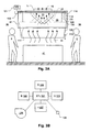
- a canopy hood 60 Another type of hood is illustrated in Fig. 2 which is called a canopy hood 60.
- This type of hood can have mirror image exhaust outlets as indicated at 21 (with filters also indicated at 20) or it can have an asymmetrical configuration.
- the canopy style hood 60 allows workers 5 to approach multiple sides of an appliance 41 such as one or more ranges.
- the canopy style hood is particularly susceptible to cross-drafts because of its open design.
- HVAC space conditioning or heating, ventilating and air-conditioning
- the invention provides a fume hood according to claim 1. Further embodiments of the invention are described in the dependent claims.
- Fig. 1A is a side view illustration of a prior art backshelf hood.
- Fig. 1B is a side view illustration of a prior art backshelf hood with side skirts.
- Fig. 2 is a side view illustration of a prior art canopy style hood with an island appliance.
- Fig. 3A is a side view illustration of a canopy style hood with adjustable side skirts which does not form part of this invention.
- Fig. 3B is a schematic illustration of a control system for the embodiment of Fig. 3A as well as other embodiments which does not form part of this invention.
- Fig. 4 is a side view illustration of a backshelf hood with a fire gap and movable side skirts and a movable back skirt which does not form part of this invention.
- Fig. 5 is a side view illustration of a canopy style hood with adjustable side skirts which does not form part of this invention.
- Fig. 6 is a figurative representation of a combination of horizontal and vertical jets to be generated at the edge of a hood according to an inventive embodiment.
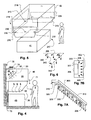
- Fig. 7A is a figurative illustration of a plenum configured to generate the vertical and horizontal jets with diagonal horizontal jets at ends of the plenum according to an inventive embodiment.
- Fig. 7B is a plan view of a typical hood showing a central location of the exhaust vent.
- Figs. 8A and 8B illustrate the position of the plenum of Fig. 7 as would be installed in a wall-type (backshelf) hood as well as a combination of the horizontal and vertical jets with side skirts according to at least one inventive embodiment.
- Figs. 9A-9C illustrate various ways of wrapping a series of horizontal jets around a corner to avoid end effects according to inventive embodiment(s).
- Fig. 9D illustrates a way of creating a hole in a plenum that redirects a small jet without a separate fixture by warping the wall of the plenum.
- Fig. 10 illustrates a canopy-style hood with vertical jets which does not form part of this invention and a configuration that provides a vertical flow pattern that is subject to an end effects problem.
- Fig. 11A and 11B illustrate configurations of a canopy hood which does not form part of this invention and that reduce or eliminate the end effect problem of the configuration of Fig. 10 .
- Fig. 12 illustrates a configuration of a canopy hood which does not form part of this invention and that reduces the end effect problem of the configuration of Fig. 10 by supporting the canopy using columns at the corners that are shaped to eliminate interactions at the ends.
- Fig. 13A illustrates a hood configuration with a sensor which does not form part of this invention and that uses incipient breach control to minimize flow volume while providing capture and containment.
- Fig. 13B illustrates an interferometric breach detector for use with the embodiment of Fig. 13A and other applications which does not form part of this invention.
- Fig. 13C illustrates an interferometer using a directional coupler and optical waveguides instead of beam splitter and mirrors which does not form part of this invention.
- Fig. 13D illustrates some mechanical issues concerning measurements that depend on the structure of turbulence which does not form part of this invention.
- Fig. 14 illustrates a combination make-up air discharge register and hood combination with a control mechanism for apportioning flow between room-mixing discharge and short-circuit discharge flows which does not form part of this invention.
- Fig. 15 illustrates a combination make-up air discharge register and hood combination with a control mechanism for apportioning flow between room-mixing discharge and a direct discharge into the exhaust zone of the hood from either outdoor air, transfer air from another conditioned space, or a mixture thereof which does not form part of this invention.
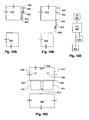
- Figs. 16A-16C illustrate drop-down skirts which do not form part of this invention and that can be manually swung out of the way and permitted to drop into place after a time interval.
- Fig. 3A is a side view illustration of a canopy style hood 61 with adjustable side skirts 105, Fumes 35 rise from a cooking appliance 41 into a suction zone of the hood 61.
- the fumes are drawn, along with air from the surrounding conditioned space 36 the hood 61 occupies, through exhaust vents and grease filters indicated at 21 by an exhaust fan (not shown in the present drawing) connected to draw through an exhaust duct 11.
- An exhaust stream 15 is then forced away from the occupied space.
- the exhaust hood 61 At one or more sides of the exhaust hood 61 are movable side skirts 105 which may be raised or lowered by means of a manual or motor drive 135.
- the manual or motor drive 135 rotates a shaft 115 which spools and unspools a pair of support wires 130 to raise and lower the side skirts 105.
- the side skirts 61 and spool 125, as well as bearings 120 and the wires 130, may be hidden inside a housing 116 with an open bottom 117.
- the manual or motor drive 135 is a motor drive controlled by a controller 121 which controls the position of the side skirts 105.
- Fig. 3B is a schematic illustration of a control system for the embodiment of Fig. 3A as well as other embodiments.
- the controller 121 may control the side skirts automatically in response to incipient breach, for example, as described in the US Patent Application, "Device and Method for Controlling/Balancing Fluid Flow-Volume Rate in Flow Channels".
- an incipient breach sensor 122 may be mounted near a point where fumes may escape due to a failure of capture and containment. Examples of sensors that may be employed in that capacity are discussed below and include humidity, temperature, chemical, flow, and opacity sensors.
- Another sensor input that may be used to control the position of the side skirts 105 is one that indicates a current load 124.
- a temperature sensor within the hood 61, a fuel flow indicator, or CO or CO2 monitor within the hood may indicate the load.
- the side skirts 105 may be lowered. This may be done in a progressive manner in proportion to the load. In the case of incipient breach, it may be done by means of an integral of the direct signal from the incipient breach sensor 122.
- any of the above sensors may be used in combination to provide greater control, as well as individually.
- a draft sensor 123 such as a velocimeter or low level pressure sensor or other changes that may indicate cross currents that can disrupt the flow of fumes into the hood. These are precisely the conditions that side skirts 105 are particularly adapted to control. Suitable transducers are known such as those used for making low level velocities and pressures. These may be located near the hood 61 to give a general indication of cross-currents. When cross-currents appear, the side skirts 105 may be lowered.
- the signals or the controller 121 is operative to provide a stable output control signal as by integrating the input signal or by other means for preventing rapid cycling, which would be unsuitable for the raising and lowering of the side skirts 105.
- the controller 121 may also control the side skirts 105 by time of day. For example, the skirts 105 may be lowered during warm-up periods when a grill is being heated up in preparation for an expected lunchtime peak load.
- the controller 121 may also control an exhaust fan 136 to control an exhaust flow rate in addition to controlling the side skirts 105 so that during periods when unhindered access to a fume source, such as a grill, is required, the side skirts 105 may be raised and the exhaust flow may be increased to compensate for the loss of protection otherwise offered by the side skirts 105.
- the controller may be configured to execute an empirical algorithm that trades off the side skirt 105 elevation against exhaust flow rate.
- side skirt 105 elevation and exhaust rate may be controlled in a master-slave manner where one variable is established, such as the side skirt 105 elevation in response to time of day, and exhaust rate is controlled in response to one or a mix of the other sensors 124, 123, 127, and/or 122.
- Fig. 4 is a side view illustration of a backshelf hood 46 with a fire safety gap 76 and movable side skirts 70 and a movable back skirt 75.
- the side skirts 70 may be one or both sides and may be manually moved or automatically driven as discussed above with reference to Figs. 3A and 3B .
- the movable back skirt 75 is located behind the appliance 40 and is raised to block the movement of fumes due to cross drafts. The back skirt could as easily be attached to the hood 46 and lowered into position.
- any of the skirts discussed above and below may be configured based on a variety of known mechanical devices.
- a skirt may hinged and pivoted into position. It may be have multiple segments such that is unfolds or unrolls like some metal garage doors.
- Fig. 5 is a side view illustration of a canopy style hood 62 with adjustable side skirts 210.
- the side skirts 210 may be manually or automatically movable. There may be two, one at either of two ends of the hood 62 or there may be more or less on adjacent sides of the hood 62, such as a back side 216. In some situations where most of the access required to the appliances can be accommodated on a front side 217 of the hood 62, it may be feasible to lower a rear skirt 218.
- Fig. 5 Also shown in Fig. 5 is a suitable location for one or more proximity control sensors 230 that be used in the present or other embodiments.
- Proximity sensors may be used to give an indication of whether access to a corresponding side of the appliance 41 is required, in a manner not unlike that of an automatic door of a public building.
- One or more proximity sensors 230 may be used to raise and lower the side skirts.
- a virtual barrier may be generated to help block cross-drafts by means of a curtain jet located at an edge of the hood.
- Fig. 6 is a figurative representation of a combination of horizontal and vertical jets to be generated at the edge of a hood according to the invention which has been shown by experiment to be advantageous in terms minimizing the exhaust flow required to obtain full capture and containment.
- the horizontal and vertical jets are made by forming holes in a plenum, for example holes of about 3-6 mm diameter with a regular spacing so that the individual jets coalesce some distance away from the openings to form a single planar jet.
- the initial velocities of the horizontal jets are preferably between 2 and 3.5 times the initial velocities of the vertical jets, the initial velocity in this case being the point at which individual jets coalesce into a single planar jet.
- Fig. 7A is a figurative illustration of a plenum 310 configured to generate the vertical 325 and horizontal 330 jets with diagonal horizontal jets 315 at ends of the plenum 310 according to an inventive embodiment.
- most hoods 307 have an exhaust vent 306 within the hood 307 recess that is centrally located so that even if the hood has a large aspect ratio, at the ends, horizontal jets 309 (330 in Fig. 7A ) are more effective at capturing exhaust if they are directed toward the center of the hood near the ends 308 of the long sides 302.
- the ends 325 of the plenum have an angled structure 320 to project the horizontal jets diagonally inwardly as indicated at 315.
- Figs. 8A and 8B illustrate the position of the plenum 310 of Fig. 7A as would be installed in a wall-type (backshelf) hood 370 as well as a combination of the horizontal and vertical jets with side skirts 365 according to.
- This illustration shows how the plenum 210 of Fig. 7B may be mounted in a backshelf hood 370.
- the figure shows the combination of the vertical and horizontal jet and the side skirts 365. In such a combination, the velocity of the vertical and horizontal jets may be reduced when the side skirts 365 are lowered and increased when the side skirts are raised.
- Fig. 8A shows the side skirts 365 in a lowered position and Fig. 8B shows the side skirts 365 in a raised position.
- the plenum 365 may be made integral to the hood and also that a similar mounting may be provided for canopy style hoods.
- Fig. 8A also shows an alternative plenum configuration 311 with a straight return 385 on one side which generates vertical 380 and horizontal 395 jets along a side of the hood 370.
- the return leg 385 although shown on one end only may be used on both ends and is also applicable canopy style hoods.
- Figs. 9A-9C illustrate various ways of wrapping a series of horizontal jets around a corner to avoid end effects according to inventive embodiment(s). These alternative arrangements may be provided by shaping a suitable plenum as indicated by the respective profile 405, 410, 415. Directional orifices may be created to direct flow inwardly at a corner without introducing a beveled portion 415A or curved portion 410A as indicated by arrows 420.
- Fig. 9D illustrates a way of creating a directional orifice in a plenum 450 to direct a small jet 451 at an angle with respect to the wall of the plenum 450. This may done by warping the wall of the plenum 450 as indicated or by other means as disclosed in the references mentioned.
- Fig. 10 illustrates a canopy-style hood 500 with vertical jets 550 and a configuration that provides a vortical flow pattern 545 that is subject to an end effects problem.
- the end effects problem is that where the vortices meet in corners, the flow vertical flow pattern is disrupted.
- the vortical flow pattern 545 works with the air curtain 550 to help ensure that fluctuating fume loads can be contained by a low average exhaust rate. But the vortex cannot make sharp right-angle bends so the quasi-stable flow is disrupted at the corners of the hood.
- Fig. 11A and 11B illustrate configurations of a canopy hood that reduce or eliminate the end effect problem of the configuration of Fig. 10 .
- a round hood 570 or one with rounded corners 576 reduces the three-dimensional effects that can break down the stable vortex flow 545.
- a toroidal vortex may be established in a curved recess 585 or 590 with the vertical jets following the rounded edge of the hood.
- the section view of Fig. 10 would roughly representative of any arbitrary slice through the hoods 576, 570 shown in plan view in Figs. 11A and 11B .
- the figures also illustrate filter banks 580 and 595. It may be impractical to make the filter banks 580 and 595 rounded, but they may be piecewise rounded as shown.
- Fig. 12 illustrates a configuration of a canopy hood 615 that reduces the end effect problem of the configuration of Fig. 10 by supporting the canopy using columns 610 at the corners that are shaped to eliminate interactions at the ends of the straight portions 620 of the hood 615.
- Vertical jets 650 do not wrap around the hood 615 and neither does the internal vortex (not illustrated) since there are separate vortices along each edge bounded by the columns 610.
- Fig. 13A illustrates a hood configuration with a sensor that uses incipient breach control to minimize flow volume while providing capture and containment.
- Incipient breach control is discussed in "Device and Method for Controlling/Balancing Fluid Flow-Volume Rate in Flow Channels". Briefly, when fumes 725 rise from a source appliance 711, and there is a lack of sufficient exhaust flow or there is a cross-draft, part of the fumes may escape as indicated by arrow 720.
- a sensor located at 715 or nearby position may detect the temperature, density, or other detectable feature of the fumes to indicate the breach. The indication may be used by a controller to control exhaust flow as discussed in the above patent or others such as US Patent No. 6,170,480 entitled “Commerical Kitchen Exhaust System”.
- a coherent light source 825 such as a laser diode emits a beam that is split by a beam splitter 830 to form two beams that are incident on a photodetector 835.
- a reference beam 831 travels directly to the detector 835.
- a sample beam 842 is guided by mirrors 840 to a sample path 860 that is open to the flow of ambient air or fumes.
- the reference and sample beams 831 and 842 interfere in the beam splitter, affecting the intensity of the light falling on the detector 835.
- the composition and temperature of the fumes creates fluctuations in the effective path length of the sample path 860 due to a fluctuating field of varying index of refraction. This in turn causes the phase difference between the reference 831 and sample 860 beams to vary causing a variation in intensity at the detector 835.
- the direct output of the detector 835 may be passed through a bandpass filter 800, an integrator 805, and a slicer (threshold detector) 810 to provide a suitable output signal.
- a bandpass filter may be useful is to eliminate slowly varying components that could not be a result of a fumes such as a person leaning against the detector, as well as changes too rapid to be characteristic of the turbulent flow field associated with a thermal plume or draft, such as motor vibrations.
- An integrator ensures that the momentary transients do not create false signals and the slicer provides a threshold level.
- an alternative way of detecting changes is to count the number of fringes detected (using for example a one-shot circuit to form pulse edges) and to generate a signal corresponding to the rate of pulses.
- a high rate of pulses indicates a correspondingly large change in the speed of light in the sample path. Large changes are associated with turbulent mixing and the escape of heat and/or gases from the cooking process.
- an alternative embodiment of a detector uses a directional coupler 830A instead of a beam splitter as in the previous embodiment.
- a waveguide 864 is used to form a sample path 860A.
- a light source 825 sends light into the direction coupler 830A which is split with one component going to the detector 835 and the other passing through the sample path 860A and back to the direction coupler 830A. Fluctuations in phase of the return light from the sample path 860A causes variations in the intensity incident on the detector 835 as in the previous embodiment.
- the interferometric detector should allow gases to pass through the measurement beam without being affected unduly by viscous forces. If the sample path is confined in a narrow channel, viscous forces will dominate and the detector will be slow to respond. This may be desirable. For example, it may avoid false positives resulting when a transient flow of gas contacts the sensor but does not remain present for a sufficiently long time or does not have sufficient concentration of contaminant to diffuse enough gas or heat into the sample gap. Also, if the sample path is too long the signal might be diminished due to an averaging effect, where the average of the speed of light in the same path remains relatively constant even though at a given point, the speed varies a great deal to the variation in the gas content or properties. These effects vary with the application and will involve some experimentation. Different detectors may be provided for different applications, for example, a hood for a grill versus one for a steam table.
- a variety of techniques can be used. Pure feedback control may be accomplished by slowly lowering the speed of a variable speed exhaust fan until a threshold degree of breach is indicated.
- the threshold may be, for example, the specified minimum frequency of pulses from the one-shot configuration described above sustained over a minimum period of time.
- the speed may be increased by a predefined amount and the process of lowering the speed repeated.
- a more refined approach may be a predictive or model-based technique in which other factors, besides breach, are used to model the fume generation process as described in the present application and in US Patent Application Serial No. 10/638,754 .
- the technique for feedback control may follow those outlined in US Patent No. 6,170,480 .
- the gap may be longer than the length scale of the temperature (or species, since the fumes may be mixed with surrounding air) fluctuations to provide a distinct signature for the signal if the gap would substantially impede the flow. Otherwise, the transport of temperature and species through the sample beam would be governed primarily by molecular diffusion making the variations slow, for example, if the sample beam were only exposed in a narrow opening. However, in some applications of a detector this may be desirable, but such applications are likely removed from typical commercial kitchen application.
- a microscale eddy is figuratively shown at 900.
- the structure of the detector may provide a space 918 that is large relative to the smallest substantial turbulent microscale as indicated at 912.
- the structure of the detector may be smaller than the microscale, but thin and short as indicated at 914 in which case viscous forces may not impede greatly the variation of the constituent gases in the sample path 910 due to turbulent convection.
- Fig. 14 illustrates a combination make-up air discharge register/hood combination 887 with a control mechanism 869 and 870 for apportioning flow between room-mixing discharge 886 and short-circuit discharge 876 flows.
- a hood 874 has a recess through which fumes 894 flow and are exhausted by an exhaust fan 879, usually located on the top of a ventilated structure.
- a make-up air unit 845 replaces the exhausted air by blowing it into a supply duct 880 which vents to a combination plenum that feeds a mixed air supply register 886 and a short-circuit supply register 876.
- the fresh air supplied by the make-up air unit 845 is apportioned between the mixed air supply register 886 and a short-circuit supply register 876 by a damper 870 whose position is determined by a motor 865 which is in turn controlled by a controller 869.
- Short-circuit supply of make-up air is believed by some to offer certain efficiency advantages.
- the controller 869 When the outside air is at a temperature that is within the comfort zone, or when its enthalpy is lower in the cooling season or higher in the heating season, most of the make-up air should be directed by the controller 869 into the occupied space through the mixed air supply register 886.
- the controller 869 should cause the make-up air to be vented through the short-circuit supply register 876.
- Fig. 15 illustrates a combination make-up air discharge register and hood combination with a control mechanism for apportioning flow between room-mixing discharge and a direct discharge into the exhaust zone of the hood from either outdoor air, transfer air from another conditioned space, or a mixture thereof.
- a blower 897 brings in transfer air, which may be used to supply some of the make-up air requirement and provide a positive enthalpy contribution to the heating or cooling load.
- the staleness of transfer air brought into the heavily ventilated environment of a kitchen is offset by the total volume of make-up (fresh) air that is required to be delivered.
- Sensors on the outside 875, the occupied space 830, in the transfer air stream and/or the space from which transfer air is drawn 831 may be provided to indicate the conditions of the source air streams.
- a mixing box 846 may be used to provide an appropriate ratio of transfer air and fresh air. The ratio will depend on the exhaust requirements of the occupied space 896. Control of the damper 870 is as discussed with reference to Fig. 14 .
- Figs. 16A-16D illustrate drop-down skirts that can be manually swung out of the way and permitted to drop into place after a the lapse of a watchdog timer.
- Figs. 16A and 16B are side views of a drop-down skirt 915 that pivots from a hinge 905 from a magnetically suspended position shown in Fig. 16A to a dropped position shown in Fig. 16B .
- a magnetic holder/release mechanism 935 which may include an electromagnet or permanent magnet, holds the skirt panel 915 in position out of the way of an area above a fume source 930.
- the skirts 915 may be released after being moved up and engaged by the magnetic holder/release mechanism 935, after a period of time by a controller 960.
- the controller 960 may be connected to a timer 970, a proximity sensor 925, and the magnetic holder/release mechanism 935.
- the proximity sensor 925 may be one such as used to activate automatic doors. If nothing is within view of the proximity sensor after the lapse of a certain time, the controller may release the skirt 915. When released by the magnetic holder/release mechanism 935, the skirt 915 falls into the position of Fig. 16B to block drafts. Preferably, as shown in the front view of Fig. 16C , there are multiple skirts 915 separated by gaps 916. A passing worker may scan the area behind the skirts 915 even though they are down if the worker moves at least partly parallel to the plane of the skirts 915.
- the magnetic ' holder/release mechanism 935 may combined with the controller 960, the timer 970, and the proximity sensor 925 in a unitary device.
- the flow control devices may be set manually or periodically, but at Intervals to provide the local load control without the benefit of real-time automatic control.
- the skirt release mechanisms described may be actuated by video cameras linked to controllers configured or trained to recognize with events or scenes.
- controllers configured or trained to recognize with events or scenes.
- the very simplest of controller configurations may be provided, where a blob larger than a particular size appears or disappears within brief interval in a scene or a scene remains stationary for a given interval.
- a controller detects the latching of the skirt as step S900 and starts a watchdog timer at step S905. Control then loops through S910 and S915 as long as scene changes are detected. Again, simple blob analysis is sufficient to determine changes in a scene.
- step S905 the skirt is released at step S920 and control returns to step S900 where the controller waits for the skirt to be latched.
- a similar control algorithm may be used to control the automatic lowering and raising of skirts in the embodiments of Figs. 3A-5 , discussed above. Instead of releasing the skirt, the skirt would be extended into a shielding position and instead of waiting for the skirt to be latched, the a scene change would be detected and the skirt automatically retracted.
- multiple sample gaps such as the two indicated at 1815 may be linked together under in a common light path by a light guide 1802 and a single directional coupler 1801 device or equivalent device.
- a light source 1835 and detector 1825 are connected by a directional coupler 1830 with focusing optics 1862 and one or more linking light guides 1864 to provide any number of sample paths, such as paths 1815.
- Fig. 18 shows a hood edge 1920 with multiple individual sample devices 1871 which conform to any of the descriptions above linked to a common controller. Although parallel connections are illustrated, serial connections of either fiber or conductor may be provided depending on the configuration.
- the raw signal from the sensor is the fringe pattern resulting from the interference of a reference beam and a sample beam.
- the properties of the sample beam change, for example due to temperature change, vapor content, or the mix of compounds resulting from cooking or other fume-generating process, the associated speed of light through the sample path generally changes.
- the length of the sample path length may be chosen based on the predicted variation due to escape of exhaust fumes.
- the configuration may be based on whether the properties will diffuse into the sample path or be transported directly by convection into the sample path. These may be matters of design choice.
- the signal and how it is conditioned also depends on design choice.
- the sample path is chosen to be large, many interference fringes may pass over the optical detector as a single bolus of gas interacts with the detector; i.e., as the bolus moves into, or diffuses fractions thereof into, the sample path such that it changes the speed of light in the sample path. If a breach occurs, under most circumstances, the flow would be a turbulent thermal convection plume containing of a mix of fumes and air from the surrounding environment producing multiple back and forth shifts in fringe pattern as the fume and ambient air boluses interact with the detector.
- the process may, if the transfer is by molecular diffusion or viscous flow due to the scale of the device, the mix of fumes and air may be averaged out producing a slower response and a single back and forth fringe shift.
- Each fringe shift may generate multiple light and dark pulses, but again this depends on the scale of the device and the particular wavelength of light chosen.
- a characteristic pattern By experimenting with the conditions of full containment and breach, one can obtain a characteristic pattern and identify it in the signal. For a grill, the thermal convection is vigorous and the properties of the fumes are such that continuous mixing with surrounding air causes a train of pulses to be generated whenever the fumes escape the hood. Thus, a simple frequency of the fringes (e.g., by converting to pulses and counting) as mentioned above may be compared to a threshold (background) level, to determine if a breach is occurring.
- a threshold background
Landscapes
- Engineering & Computer Science (AREA)
- Chemical & Material Sciences (AREA)
- Combustion & Propulsion (AREA)
- Mechanical Engineering (AREA)
- General Engineering & Computer Science (AREA)
- Ventilation (AREA)
- Characterised By The Charging Evacuation (AREA)
- Exhaust-Gas Circulating Devices (AREA)
- Prevention Of Fouling (AREA)
- Sampling And Sample Adjustment (AREA)
Claims (8)
- Eine Dunstabzugshaube (307, 370, 500, 570, 576, 615), aufweisend:einen Haubenabschnitt, der mit einem Absaugsystem verbindbar ist und eine Aussparung und einen unteren Rand darum herum aufweist, wobei der Haubenabschnitt eingerichtet ist, eine Dunstquelle abzudecken, undeinen Strahlerzeuger, der an dem unteren Rand positioniert und eingerichtet ist, eine Kombination von ersten und zweiten Strahlen (325, 330; 380, 395; 550, 650) an dem unteren Rand an einem vorderen und seitlichen Abschnitten davon zu erzeugen, wobei die ersten (330; 395) eine relativ horizontale Richtung haben und einen planaren Strahl bilden und die zweiten (325; 380; 550; 650) eine relativ vertikale Richtung haben und einen planaren Strahl bilden, wobei die ersten (330, 395) in Richtung zu und direkt in die Haubenabschnittsaussparung hinein gerichtet sind.
- Die Dunstabzugshaube (307; 370; 500; 570; 576; 615) gemäß Anspruch 1, wobei mindestens einer der ersten und der zweiten Strahlen (325, 330; 380, 395; 550; 650) durch eine Reihe von kreisförmige Strahlen definiert ist, die entlang einer Linie entlang dem unteren Rand angeordnet sind.
- Die Dunstabzugshaube (307; 370; 500; 570; 576; 615) gemäß Anspruch 1 oder 2, wobei sowohl die ersten als auch die zweiten Strahlen (325, 330; 380, 395; 550, 650) durch eine Reihe von kreisförmigen Strahlen definiert sind.
- Die Dunstabzugshaube (307; 370; 500; 570; 576; 615) gemäß irgendeinem der Ansprüche 1 bis 3, wobei die ersten und die zweiten Strahlen (325, 330; 380, 395; 550, 650) in Paaren proximal zueinander definiert sind.
- Die Dunstabzugshaube (307; 370; 500; 570; 576; 615) gemäß irgendeinem der Ansprüche 1 bis 4, wobei die ersten und die zweiten Strahlen (325, 330; 380, 395; 550, 650) durch eine Sammelkammer (310) definiert sind.
- Die Dunstabzugshaube (307; 370; 500; 570; 576; 615) gemäß irgendeinem der Ansprüche 1 bis 5, wobei die ersten und die zweiten Strahlen (325, 330; 380, 395; 550; 650) durch jeweilige Reihen von kreisförmigen Strahlen definiert sind, die entlang jeweiligen Linien entlang dem unteren Rand angeordnet sind.
- Die Dunstabzugshaube (576) gemäß irgendeinem der Ansprüche 1 bis 6, wobei der untere Haubenabschnittsrand an jeweiligen Enden davon Ecken aufweist, wobei die Ecken angeschrägt (41.5A) oder gekrümmt (410A) sind und die ersten Strahlen (330; 395) senkrecht zu dem unteren Rand ausgerichtet sind.
- Die Dunstabzugshaube gemäß einem der Ansprüche 1 bis 6, wobei der untere Haubenabschnittsrand Ecken aufweist, wobei die ersten Strahlen (420) zwischen den Ecken senkrecht zu dem unteren Rand und in einer Richtung, die relativ zu dem unteren Rand proximal zu den Ecken diagonal ist, und dadurch an den Ecken in Richtung einer Mitte des Haubenabschnitts ausgerichtet sind.
Priority Applications (1)
| Application Number | Priority Date | Filing Date | Title |
|---|---|---|---|
| PL05775069T PL1778418T5 (pl) | 2004-07-23 | 2005-07-25 | Ulepszenie sterowania systemów wyciągowych |
Applications Claiming Priority (2)
| Application Number | Priority Date | Filing Date | Title |
|---|---|---|---|
| US59088904P | 2004-07-23 | 2004-07-23 | |
| PCT/US2005/026378 WO2006012628A2 (en) | 2004-07-23 | 2005-07-25 | Improvements for control of exhaust systems |
Publications (4)
| Publication Number | Publication Date |
|---|---|
| EP1778418A2 EP1778418A2 (de) | 2007-05-02 |
| EP1778418A4 EP1778418A4 (de) | 2009-09-02 |
| EP1778418B1 true EP1778418B1 (de) | 2010-07-07 |
| EP1778418B2 EP1778418B2 (de) | 2013-11-06 |
Family
ID=35786774
Family Applications (1)
| Application Number | Title | Priority Date | Filing Date |
|---|---|---|---|
| EP05775069.7A Expired - Lifetime EP1778418B2 (de) | 2004-07-23 | 2005-07-25 | Verbesserungen zur steuerung von abgassystemen |
Country Status (7)
| Country | Link |
|---|---|
| US (7) | US8038515B2 (de) |
| EP (1) | EP1778418B2 (de) |
| AT (1) | ATE473062T1 (de) |
| CA (2) | CA2573955C (de) |
| DE (1) | DE602005022198D1 (de) |
| PL (1) | PL1778418T5 (de) |
| WO (1) | WO2006012628A2 (de) |
Cited By (5)
| Publication number | Priority date | Publication date | Assignee | Title |
|---|---|---|---|---|
| US8038515B2 (en) | 2004-07-23 | 2011-10-18 | Oy Halton Group Ltd. | Control of exhaust systems |
| US8734210B2 (en) | 2007-05-04 | 2014-05-27 | Oy Halton Group Ltd. | Autonomous ventilation system |
| US8795040B2 (en) | 2007-08-28 | 2014-08-05 | Oy Halton Group Ltd. | Autonomous ventilation system |
| US9574779B2 (en) | 2008-04-18 | 2017-02-21 | Oy Halton Group, Ltd. | Exhaust apparatus, system, and method for enhanced capture and containment |
| US10082299B2 (en) | 2008-12-03 | 2018-09-25 | Oy Halton Group Ltd. | Exhaust flow control system and method |
Families Citing this family (52)
| Publication number | Priority date | Publication date | Assignee | Title |
|---|---|---|---|---|
| ATE414876T1 (de) * | 2000-01-10 | 2008-12-15 | Oy Halton Group Limited | Dunstabzugshaube mit luftvorhang |
| US20110005507A9 (en) * | 2001-01-23 | 2011-01-13 | Rick Bagwell | Real-time control of exhaust flow |
| US7775865B2 (en) * | 2004-06-22 | 2010-08-17 | Oy Halton Group Ltd. | Set and forget exhaust controller |
| CA2593242C (en) | 2005-01-06 | 2014-05-20 | Oy Halton Group, Ltd | Low profile exhaust hood |
| SG135068A1 (en) * | 2006-02-21 | 2007-09-28 | Kim Lui So | Controls for ventilation and exhaust ducts and fans |
| DK2489943T3 (en) | 2006-04-18 | 2018-10-22 | Oy Halton Group Ltd | Modular weight for large kitchens |
| US7836878B1 (en) * | 2006-05-08 | 2010-11-23 | Agha Nazih S | Appliance heat isolation system for attachment to a vent hood |
| US8141624B2 (en) * | 2006-06-28 | 2012-03-27 | Martin Jeffrey R | Apparatus for heating a restaurant kitchen, dining room, and hot water supply |
| DE102006041581A1 (de) * | 2006-09-05 | 2008-03-06 | BSH Bosch und Siemens Hausgeräte GmbH | Verfahren zum Schutz vor Überhitzung einer Dunstabzugsvorrichtung |
| US7947123B2 (en) * | 2006-11-10 | 2011-05-24 | Illinois Tool Works Inc. | Impact filter with grease trap |
| CA2640840C (en) | 2007-10-09 | 2016-01-26 | Oy Halton Group Ltd. | Damper suitable for liquid aerosol-laden flow streams |
| US20090211564A1 (en) * | 2008-02-22 | 2009-08-27 | Chi-Chuan Pan | Smoke Exhaust With An Air Curtain Fan |
| AU2014271273B2 (en) * | 2008-04-18 | 2017-02-16 | Oy Halton Group Ltd. | Exhaust apparatus, system, and method for enhanced capture and containment |
| EP2290293A4 (de) * | 2008-06-25 | 2012-09-26 | Shan Dong University | Dunstabzugshaube |
| EP2196738B1 (de) * | 2008-12-10 | 2013-10-23 | Electrolux Home Products Corporation N.V. | Absaughaube |
| US20100318230A1 (en) * | 2009-06-15 | 2010-12-16 | Guopeng Liu | Kitchens exhaust hood and make-up air handling unit optimal speed control system |
| US20110056479A1 (en) * | 2009-09-08 | 2011-03-10 | Niro-Plan Ag. | Variable ventilation method and system |
| US8505530B2 (en) * | 2009-11-19 | 2013-08-13 | Itw Food Equipment Group Llc | Commercial kitchen exhaust system |
| CN102782415B (zh) * | 2010-01-13 | 2016-06-29 | 奥义霍尔顿集团有限公司 | 烤箱排风罩方法、装置以及系统 |
| CN102374561B (zh) * | 2010-08-17 | 2016-06-15 | 博西华电器(江苏)有限公司 | 具有烟气自动检测装置的吸油烟机及其控制方法 |
| TWI408317B (zh) * | 2010-12-15 | 2013-09-11 | Univ Nat Taiwan Science Tech | 具有抗擾動氣流能力的排油煙機 |
| US20120152227A1 (en) * | 2010-12-15 | 2012-06-21 | General Electric Company | Forced convection cooling of led lighting and electronics in a range hood appliance |
| US9506668B2 (en) * | 2011-05-03 | 2016-11-29 | Broan-Nutone Llc | Make-up air system and method |
| US8908024B2 (en) * | 2011-06-29 | 2014-12-09 | Honeywell International Inc. | System for detecting an item within a specified zone |
| US9909765B2 (en) | 2011-07-07 | 2018-03-06 | Oy Halton Group Ltd. | Exhaust hood methods, devices, and systems |
| US8939826B2 (en) | 2011-07-15 | 2015-01-27 | Unilux V.F.C. Corp. | HVAC apparatus with HRV/ERV unit and vertical fan coil unit |
| US8968061B2 (en) * | 2011-08-01 | 2015-03-03 | Chrysler Group Llc | Containment hood |
| KR101952847B1 (ko) * | 2012-10-12 | 2019-02-27 | 삼성전기주식회사 | 워피지 측정 시스템 및 워피지 측정 방법 |
| CA2897181A1 (en) * | 2013-01-11 | 2014-07-17 | Lumense, Inc. | System and method for sensing ammonia in a fluid |
| US9897328B2 (en) * | 2013-05-02 | 2018-02-20 | William B. McEvoy | Tabletop cooking assembly |
| US10137317B2 (en) | 2013-05-14 | 2018-11-27 | The Boeing Company | Aircraft air supply systems for reducing effective altitude experienced at selected locations |
| US10232947B2 (en) * | 2013-05-14 | 2019-03-19 | The Boeing Company | Aircraft air supply systems for reducing effective altitude of flight decks |
| CN103383116A (zh) * | 2013-05-19 | 2013-11-06 | 关云龙 | 装设喷射风屏装置防护面板的洁烟机 |
| CN105765311B (zh) * | 2013-11-26 | 2019-03-08 | 松下知识产权经营株式会社 | 供排型换气装置 |
| US10498738B2 (en) * | 2015-06-07 | 2019-12-03 | Apple Inc. | Account access recovery system, method and apparatus |
| US10376936B2 (en) * | 2016-06-21 | 2019-08-13 | Gurmeet Singh | Method and apparatus of optimizing performance of fume hoods |
| KR101740675B1 (ko) * | 2016-08-31 | 2017-05-26 | 주식회사 재진엔지니어링 | 국소배기장치용 흡입장치 |
| US10384243B2 (en) * | 2017-03-15 | 2019-08-20 | L.B.T. (Nantong) Laboratory Systems Engineering Co., Ltd. | Air replenishing fume hood |
| CN107575985A (zh) * | 2017-08-31 | 2018-01-12 | 杭州老板电器股份有限公司 | 一种厨房空气净化系统 |
| US10810860B1 (en) * | 2018-01-03 | 2020-10-20 | Objectvideo Labs, Llc | Intelligent vent hood |
| CN110631099B (zh) * | 2018-06-25 | 2025-08-12 | 青岛海尔智慧厨房电器有限公司 | 风幕吸油烟机 |
| US12066192B2 (en) | 2018-11-29 | 2024-08-20 | Broan-Nutone Llc | Smart indoor air venting system |
| CN111853882B (zh) * | 2019-04-28 | 2023-06-16 | 博西华电器(江苏)有限公司 | 抽油烟机及其过滤装置 |
| JP7605827B2 (ja) * | 2019-08-07 | 2024-12-24 | エーエヌエイチ イノベーション, インコーポレイテッド | 可変ファンドライブ付き可動式再循環グリル |
| CN110360635B (zh) * | 2019-08-15 | 2025-01-03 | 湖北玥研科技有限公司 | 气体净化一体机 |
| WO2021046181A1 (en) * | 2019-09-05 | 2021-03-11 | North American Kitchen Solutions, Incorporated | Exhaust system for use in kitchen applications |
| US11573010B2 (en) | 2019-10-28 | 2023-02-07 | Lg Electronics Inc. | Self-cleaning kitchen hood |
| CN111282717B (zh) * | 2020-02-13 | 2022-04-08 | 上海白沙不锈钢制品有限公司 | 静电式油烟净化器的控制方法、系统、存储介质以及装置 |
| CN114110691B (zh) * | 2021-11-26 | 2023-12-05 | Tcl空调器(中山)有限公司 | 一种厨房通风系统及其控制方法 |
| US11454402B1 (en) | 2021-12-01 | 2022-09-27 | Mcevoy William B | Tabletop cooking assembly |
| CN114353142B (zh) * | 2022-01-07 | 2024-06-25 | 杭州老板电器股份有限公司 | 一种集烟组件、吸油烟机及集烟组件的控制方法 |
| US12491056B2 (en) * | 2023-03-16 | 2025-12-09 | Vairion LLC | Aerosol removal system |
Family Cites Families (218)
| Publication number | Priority date | Publication date | Assignee | Title |
|---|---|---|---|---|
| US913465A (en) * | 1908-04-29 | 1909-02-23 | Arthur Brouillet | Stove-hood. |
| US2833615A (en) | 1952-10-03 | 1958-05-06 | Houdry Process Corp | Abatement of smog in flue gases |
| US2853367A (en) | 1954-02-10 | 1958-09-23 | Oxy Catalyst Inc | Cartridge type catalytic exhaust cleaner |
| DE1679545U (de) | 1954-04-30 | 1954-07-08 | Huwil Werke Gmbh | Rollenbeschlag. |
| US2743529A (en) | 1954-07-06 | 1956-05-01 | Oxy Catalyst Inc | Drying oven and operation thereof |
| US2862095A (en) | 1954-10-07 | 1958-11-25 | Philco Corp | Vapor treating means |
| CH334686A (de) | 1955-09-12 | 1958-12-15 | Ingenieurbureau W Hausammann & | Veränderbare Düse, insbesondere Lavaldüse für Windkanäle |
| US2933080A (en) | 1956-03-07 | 1960-04-19 | Oxy Catalyst Inc | Cooking apparatus |
| JPS4113143Y1 (de) | 1964-04-02 | 1966-06-22 | ||
| FR1418065A (fr) | 1964-07-16 | 1965-11-19 | Loire Atel Forges | Procédé et dispositif pour la régulation du captage des gaz d'affinage à l'oxygène |
| US3381134A (en) | 1964-10-05 | 1968-04-30 | Philip C. Wolf | Mass flow indicating means including an interferometer system |
| US3323439A (en) | 1966-01-28 | 1967-06-06 | Weaver | Damper and fire control device for ventilators |
| US3400649A (en) | 1967-01-26 | 1968-09-10 | Donald D. Jensen | Ventilating system including fume removal means |
| DE1679545A1 (de) | 1967-07-18 | 1971-03-25 | Licentia Gmbh | Absaugehaube |
| US3457850A (en) * | 1967-12-11 | 1969-07-29 | Elster S Air Conditioning | Air curtain ventilator |
| US3536457A (en) | 1968-02-21 | 1970-10-27 | Gen Electric | Catalytic oxidation unit for domestic oven exhaust |
| SE339300B (de) | 1968-05-14 | 1971-10-04 | Electrolux Ab | |
| US3513766A (en) | 1968-06-24 | 1970-05-26 | Willard K Ahlrich | Ventilating hood |
| FR2030532A5 (de) | 1969-07-03 | 1970-11-13 | Snecma | |
| JPS5248645Y1 (de) | 1969-11-11 | 1977-11-05 | ||
| GB1377831A (en) | 1972-04-17 | 1974-12-18 | Secr Defence | Interferometers for fluid flow measurements |
| FR2190404B2 (de) | 1972-07-03 | 1976-01-16 | Etu Expl Matier S Premie Fr | |
| US3809480A (en) | 1972-07-24 | 1974-05-07 | Gen Dynamics Corp | Method and apparatus for surveying the velocities of a flow field |
| GB1450911A (en) | 1973-01-17 | 1976-09-29 | Nat Res Dev | Laser doppler velocimetry |
| US3829285A (en) | 1973-02-28 | 1974-08-13 | Mc Quay Perfex Inc | Recuperators for incinerators |
| US3952640A (en) | 1973-03-01 | 1976-04-27 | Vent-Cair, Inc. | Apparatus and method for extracting grease and smoke, and method of installing the same |
| JPS5248645B2 (de) | 1973-07-30 | 1977-12-12 | ||
| US3943836A (en) | 1974-08-15 | 1976-03-16 | Vent-Cair, Inc. | Apparatus for removing fumes from the space above a cooking appliance in a restaurant |
| CA1081030A (en) | 1974-09-26 | 1980-07-08 | Irvin R. Kuechler | Method of installing kitchen grease hood |
| US4056877A (en) | 1974-09-26 | 1977-11-08 | Vent-Cair, Inc. | Method of installing apparatus for extracting grease and smoke |
| CA1069749A (en) | 1975-02-24 | 1980-01-15 | Econovent Systems | Ventilating apparatus |
| US3978777A (en) | 1975-02-24 | 1976-09-07 | Nett Louis A | Ventilating apparatus |
| US4047519A (en) | 1975-02-24 | 1977-09-13 | Nett Louis A | Ventilating apparatus |
| JPS51132645U (de) | 1975-04-18 | 1976-10-25 | ||
| DE2640684C2 (de) | 1975-09-11 | 1981-11-26 | Matsushita Electric Industrial Co., Ltd., Kadoma, Osaka | Brat- bzw. Kochofen |
| US4147502A (en) | 1975-09-15 | 1979-04-03 | Roper Corporation | System for control of thermal potential |
| US4043319A (en) | 1975-09-18 | 1977-08-23 | Jensen Donald D | Exhaust hood |
| US4085736A (en) | 1975-10-01 | 1978-04-25 | Vent-Cair, Inc. | Grease-hood apparatus |
| US4050368A (en) | 1976-01-02 | 1977-09-27 | Marion L. Eakes Co. | Exhaust system for industrial processes |
| US4346962A (en) * | 1976-01-21 | 1982-08-31 | Lawrence Holmes, Jr | Light analyzing lenticular screen for viewing stereo images |
| US4117833A (en) | 1977-02-16 | 1978-10-03 | Mueller Robert H | Exhaust hood with adjustable air injection nozzle |
| US4134394A (en) | 1977-02-24 | 1979-01-16 | Otenbaker James T | Air ventilation system |
| US4105015A (en) | 1977-03-09 | 1978-08-08 | William C. Isom | Exhaust hood energy saving device |
| US4109641A (en) | 1977-05-25 | 1978-08-29 | Air Master Systems, Inc. | Adapter manifold for ventilation hood |
| US4146017A (en) | 1977-08-08 | 1979-03-27 | Overton Jr Duncan E | Hood system for cooking equipment |
| US4155348A (en) | 1977-10-11 | 1979-05-22 | Ahlrich Wilard K | Ventilating apparatus |
| US4213947A (en) | 1977-10-13 | 1980-07-22 | Champion International Corporation | Emission control system and method |
| US4160407A (en) | 1977-11-18 | 1979-07-10 | Bell Telephone Laboratories, Incorporated | Ventilating system |
| US4153044A (en) | 1978-01-23 | 1979-05-08 | Nett Louis A | Backshelf ventilating hood |
| US4138220A (en) | 1978-02-13 | 1979-02-06 | Colonial Metals, Inc. | Apparatus for catalytic oxidation of grease and fats in low temperature fumes |
| US4211154A (en) | 1978-09-20 | 1980-07-08 | Eakes Marion L | Apparatus for improving the collection of gases into a suction orifice |
| US4475534A (en) | 1978-11-30 | 1984-10-09 | Moriarty Daniel J | Ventilating system for kitchen stove |
| US4286572A (en) | 1979-03-08 | 1981-09-01 | Cambridge Engineering, Inc. | Ventilating hood |
| SE419830B (sv) | 1979-05-21 | 1981-08-31 | Leif Ingemar Lind | Sett och anordning for utsugning av fororenad luft |
| GB2054143B (en) | 1979-07-11 | 1983-06-29 | Atomic Energy Authority Uk | Measurement of the size of particles dispersed in a fluid |
| US4373507A (en) | 1980-10-09 | 1983-02-15 | Jamestown Group | Stove construction |
| US4346692A (en) | 1980-11-26 | 1982-08-31 | Mccauley Lewis C | Make-up air device for range hood |
| US4467782A (en) | 1981-08-19 | 1984-08-28 | Russell Robert E | Ventilating system for use with devices which produce airborne impurities |
| DE3144777A1 (de) | 1981-11-11 | 1983-05-19 | Imperial-Werke GmbH, 4980 Bünde | Verfahren zum absaugen und filtern von ueber einer kochstelle einer kueche entstehendem wrasen und anreicherung der kuechenluft mit frischluft und vorrichtung zur durchfuehrung des verfahrens |
| US4398415A (en) | 1981-12-10 | 1983-08-16 | The United States Of America As Represented By The Secretary Of The Air Force | Swing link flexible wind tunnel nozzle |
| US4497242A (en) | 1982-02-11 | 1985-02-05 | Barber-Colman Company | Ventilation control system |
| GB2132335A (en) | 1982-12-21 | 1984-07-04 | Chung Tsung Cheng | Apparatus for exhausting gaseous emissions during cooking |
| SE8305034L (sv) | 1983-09-19 | 1985-03-20 | Bahco Ventilation Ab | Utsugningsanordning |
| US4484563A (en) * | 1983-10-11 | 1984-11-27 | Alco Foodservice Equipment Company | Air ventilation and pollution cleaning system |
| US4483316A (en) | 1983-10-11 | 1984-11-20 | Alco Foodservice Equipment Company | Air ventilation system |
| US4528898A (en) * | 1984-03-05 | 1985-07-16 | Imec Corporation | Fume hood controller |
| FI77163C (fi) | 1984-03-09 | 1989-02-10 | Halton Oy | Luftrenare. |
| JPS60213753A (ja) | 1984-04-09 | 1985-10-26 | Matsushita Seiko Co Ltd | クリ−ンベンチ |
| US4556046A (en) | 1984-04-12 | 1985-12-03 | Pizza Hut, Inc. | Hood for oven in pizza delivery vehicle |
| US4586486A (en) | 1984-07-06 | 1986-05-06 | National Air Systems, Inc. | Multilevel air distribution panel for air ventilation hood |
| US4553992A (en) * | 1984-10-17 | 1985-11-19 | Boissinot Jean Guy | Scrubber apparatus for purifying foul air produced during an embalming, an autopsy or the like |
| FI71831C (fi) | 1985-04-12 | 1987-02-09 | Halton Oy | Fraonluftsanordning. |
| US4617909A (en) | 1985-05-06 | 1986-10-21 | Molitor Victor D | Method of and device for preventing smoke curling from underneath the hood of a grease extraction ventilator |
| DE3519189A1 (de) | 1985-05-29 | 1986-12-04 | Buderus Ag, 6330 Wetzlar | Dunstabzugshaube |
| US4781460A (en) | 1986-01-08 | 1988-11-01 | Coulter Electronics Of New England, Inc. | System for measuring the size distribution of particles dispersed in a fluid |
| US4655194A (en) | 1986-04-15 | 1987-04-07 | Heat Transfer Specialties, Inc. | System for removing fumes |
| JPS6391442A (ja) | 1986-10-06 | 1988-04-22 | Aruku Kk | ガスレンジから発生する煙等の換気方法 |
| US4773311A (en) | 1986-11-24 | 1988-09-27 | Phoenix Controls Corporation | Make up air controller for use with fume hood systems |
| JPS6391442U (de) | 1986-12-04 | 1988-06-13 | ||
| FI83696B (fi) | 1987-01-27 | 1991-04-30 | Halton Oy | Foerfarande foer reglering av ventilation. |
| US4878892A (en) | 1987-02-10 | 1989-11-07 | Drug Delivery Systems Inc. | Electrolytic transdermal delivery of polypeptides |
| JPS63204048A (ja) | 1987-02-19 | 1988-08-23 | Fujita Corp | インバ−タ−付全自動レンジフ−ド |
| JPS63251741A (ja) | 1987-04-08 | 1988-10-19 | Nagano Pref Gov Roudou Kijiyun Kyokai Rengokai | 流速勾配エアカ−テン装置 |
| DE3716257A1 (de) | 1987-05-15 | 1988-11-24 | Takeo Imai | Verfahren und vorrichtung zum auffangen verschmutzter substanzen |
| US4788905A (en) | 1987-06-10 | 1988-12-06 | Kohorn H Von | Combination cooking, eating and ventilating system |
| JPS6484039A (en) | 1987-09-24 | 1989-03-29 | Matsushita Electric Works Ltd | Smoke venting hood |
| AT390325B (de) | 1988-03-11 | 1990-04-25 | Tabarelli Werner | Interferometrische einrichtung zur messung von lageaenderungen eines beweglichen bauteiles |
| US5063834A (en) | 1988-06-10 | 1991-11-12 | Halton Oy | Focussed ventilation procedure and focussed ventilation means |
| US5074198A (en) * | 1988-06-10 | 1991-12-24 | Halton Oy | Focussed ventilation procedure for a work spot and apparatus used in the procedure |
| US5251608A (en) | 1988-08-19 | 1993-10-12 | Cameron Cote | Air canopy ventilation system |
| CA1272064A (en) | 1988-08-19 | 1990-07-31 | Cameron Cote | Air canopy cooking system |
| US5241608A (en) * | 1988-11-25 | 1993-08-31 | Eastman Kodak Company | Method for estimating velocity vector fields from a time-varying image sequence |
| US4903685A (en) | 1989-01-24 | 1990-02-27 | Melink Stephen K | Variable exhaust controller for commercial kitchens |
| US4944285A (en) | 1989-05-25 | 1990-07-31 | Glassman Joseph T | Exhaust hood for pizza ovens |
| DE3918870C2 (de) | 1989-06-09 | 1995-06-29 | Roehl Hager Hannelore | Verfahren und Einrichtung zum Absaugen von Dämpfen und Dunststoffen |
| US4944283A (en) | 1989-08-29 | 1990-07-31 | Paloma Kogyo Kabushiki Kaisha | Gas burner |
| US4974579A (en) | 1989-09-28 | 1990-12-04 | Rheem Manufacturing Company | Induced draft, fuel-fired furnace apparatus having an improved, high efficiency heat exchanger |
| FI84096B (fi) | 1990-01-31 | 1991-06-28 | Halton Oy | Undertakskonstruktion och foerfarande foer att bringa luften att stroemma i samband med undertakskonstruktionen. |
| FI88433C (fi) | 1990-01-31 | 1994-08-17 | Halton Oy | Anordning foer ingaongs- och utgaongsluft och luftkonditioneringsfoerfarande |
| JPH03247937A (ja) | 1990-02-23 | 1991-11-06 | Mitsubishi Electric Corp | レンジフード |
| CH682512A5 (de) | 1990-03-02 | 1993-09-30 | Zurecon Ag | Dampfabzugeinrichtung. |
| JP2654227B2 (ja) | 1990-04-13 | 1997-09-17 | 株式会社熊谷組 | 排気方法 |
| US5216075A (en) * | 1990-05-04 | 1993-06-01 | Arco Chemical Technology, L.P. | Impact resistant polyblends of polyamides, acid copolymers and anhydride functionalized elastomers |
| US5322473A (en) | 1990-05-17 | 1994-06-21 | Quality Air Systems, Inc. | Modular wall apparatus and method for its use |
| CH680834A5 (de) | 1990-06-19 | 1992-11-30 | Analyse Data Finance Sa | |
| JP2626189B2 (ja) | 1990-06-29 | 1997-07-02 | コクヨ株式会社 | 喫煙装置 |
| JP3134159B2 (ja) | 1990-07-05 | 2001-02-13 | 株式会社トルネックス | 人工竜巻発生機構及びその装置並びにこれを用いた照明装置 |
| JPH04113143A (ja) | 1990-08-31 | 1992-04-14 | Kansai Electric Power Co Inc:The | 厨房用レンジ装置 |
| US5092227B1 (en) | 1990-09-28 | 1995-02-14 | Landis & Gyr Powers Inc | Apparatus for controlling the ventilation of laboratory fume hoods |
| US5764579A (en) | 1990-10-01 | 1998-06-09 | American Auto-Matrix, Inc. | System for controlling laboratories with fume hoods |
| US5139009A (en) | 1990-10-11 | 1992-08-18 | Walsh Leo B | Exhaust ventilation control system |
| IT1244170B (it) | 1990-12-04 | 1994-07-08 | Cise Spa | Apparecchiatura laser per la misura della velocita' di un fluido. |
| DE4114329A1 (de) | 1991-05-02 | 1992-11-05 | Standard Elektrik Lorenz Ag | Dunstabzugshaube mit luftschleier |
| US5240455A (en) | 1991-08-23 | 1993-08-31 | Phoenix Controls Corporation | Method and apparatus for controlling a fume hood |
| US5215075A (en) | 1991-09-27 | 1993-06-01 | Heat And Control, Inc. | Cooking system having an efficient pollution incinerating heat exchanger |
| JPH068242A (ja) | 1992-01-10 | 1994-01-18 | Japan Synthetic Rubber Co Ltd | ゴムの粉砕方法 |
| DE4203916C1 (de) * | 1992-02-11 | 1993-04-29 | Hannelore 8400 Regensburg De Roehl-Hager | |
| JPH05248645A (ja) | 1992-03-03 | 1993-09-24 | Shinritsu Denki Kk | 厨房用電磁調理装置 |
| FI96901C (fi) | 1992-04-16 | 1996-09-10 | Halton Oy | Menetelmä ja laite ilmavirtauksen säädössä ja äänenvaimennuksessa |
| JP3162192B2 (ja) | 1992-06-18 | 2001-04-25 | 高砂熱学工業株式会社 | 給水管路の防食法および装置 |
| US5622100A (en) | 1992-07-31 | 1997-04-22 | Ayrking Corporation | Catalytic assembly for cooking smoke abatement |
| JP3247937B2 (ja) | 1992-09-24 | 2002-01-21 | 株式会社日立製作所 | 論理集積回路 |
| US5311930A (en) | 1992-11-17 | 1994-05-17 | Bruenn Paul R | Heat reclamation device |
| ES2067338T3 (es) | 1993-02-23 | 1995-03-16 | Maimer Gmbh | Campana de extraccion de humos, en especial para aplicacion en cocinas industriales. |
| US5414509A (en) | 1993-03-08 | 1995-05-09 | Associated Universities, Inc. | Optical pressure/density measuring means |
| FR2705766B1 (fr) | 1993-05-24 | 1995-08-25 | Scholtes Ets Eugen | Dispositif pour l'oxydation catalytique des gaz et fumées, produits dans un four de cuisson domestique. |
| US5713346A (en) | 1993-08-11 | 1998-02-03 | D.E.R. Investments Ltd. | Apparatus and method for removing fumes from the space above a cooking appliance |
| US6058929A (en) | 1994-05-12 | 2000-05-09 | Randell Manufacturing, Inc. | Adjustable exhaust hood with air curtain |
| US5522377A (en) | 1994-05-12 | 1996-06-04 | Randell Manufacturing, Inc. | Adjustable exhaust hood |
| US5580535A (en) | 1994-07-07 | 1996-12-03 | Engelhard Corporation | System and method for abatement of food cooking fumes |
| US5528040A (en) | 1994-11-07 | 1996-06-18 | Trustees Of Princeton University | Ring-down cavity spectroscopy cell using continuous wave excitation for trace species detection |
| DE4443176C1 (de) | 1994-12-05 | 1996-05-02 | Gaggenau Werke | Geräuschreduzierte Dunstabzugshaube |
| FR2728331A1 (fr) | 1994-12-15 | 1996-06-21 | Cerga | Procede et dispositif de modulation de la ventilation de locaux |
| US5690093A (en) | 1995-01-19 | 1997-11-25 | Nutone, Inc. | Ventilator controller with variably adjustable fan and light |
| US5597354A (en) | 1995-06-13 | 1997-01-28 | Johnson Service Company | Indoor air quality control for constant volume heating, ventilating and air conditioning units |
| FR2736567B1 (fr) | 1995-07-13 | 1997-08-08 | Europ Equip Menager | Systeme d'aspiration d'emanations, notamment pour hotte aspirante |
| US5657744A (en) | 1995-09-15 | 1997-08-19 | Vianen; Hendrikus Joseph | Ventilation ceiling with integral air filter units |
| CA2169702C (en) | 1996-02-16 | 2001-02-13 | Christian Guay | Exhaust hood apparatus |
| DE19613513A1 (de) | 1996-04-04 | 1997-10-09 | Roehl Hager Hannelore | Verfahren zum Eingrenzen, Erfassen und Absaugen von Dunst, Staub oder dergleichen sowie Einrichtung zur Durchführung des Verfahrens |
| WO1997048479A1 (en) | 1996-06-19 | 1997-12-24 | Halton Company | Kitchen exhaust system with catalytic converter |
| EP0921722A1 (de) * | 1996-06-24 | 1999-06-16 | Board Of Regents, The University Of Texas System | Automatische, geschlossene und rückführende filtrieranlage für die wassertierzucht |
| US5874292A (en) | 1996-07-11 | 1999-02-23 | Mcminn, Jr.; Pearson Vernie | System and method for vent hood cleaning and comprehensive bioremediation of kitchen grease |
| JP2820132B2 (ja) | 1996-09-09 | 1998-11-05 | 日本電気株式会社 | 半導体装置およびその製造方法 |
| US5718219A (en) | 1997-01-10 | 1998-02-17 | Boudreault; Jean-Pierre | Kitchen exhaust hood assembly |
| US5716268A (en) | 1997-02-18 | 1998-02-10 | Plymovent Ab | Device for removal of deleterious impurities from room atmosphere |
| GB9704250D0 (en) | 1997-02-28 | 1997-04-16 | Kitchen Ventilation Services L | Ventilation systems |
| JPH10288371A (ja) | 1997-04-16 | 1998-10-27 | Shinpo Kk | 排気装置 |
| US5882254A (en) | 1997-06-09 | 1999-03-16 | Siemens Building Technologies, Inc. | Laboratory fume hood controller utilizing object detection |
| JPH113143A (ja) | 1997-06-10 | 1999-01-06 | Kokusai Electric Co Ltd | バックアップ電源信号分配器 |
| US6062482A (en) | 1997-09-19 | 2000-05-16 | Pentech Energy Solutions, Inc. | Method and apparatus for energy recovery in an environmental control system |
| US6089970A (en) | 1997-11-24 | 2000-07-18 | The Regents Of The University Of California | Energy efficient laboratory fume hood |
| US5960786A (en) | 1998-01-06 | 1999-10-05 | Gemini Steel, Inc. | Adjustable cartridge filter for cartridge ventilator |
| JPH11311058A (ja) * | 1998-02-27 | 1999-11-09 | Daiwa House Ind Co Ltd | 窓、ドア等の可動建具材の操作力支援装置 |
| US6252689B1 (en) | 1998-04-10 | 2001-06-26 | Aircuity, Inc. | Networked photonic signal distribution system |
| US6351999B1 (en) | 1998-06-25 | 2002-03-05 | Endress + Hauser Flowtec Ag | Vortex flow sensor |
| JP2000081216A (ja) | 1998-09-04 | 2000-03-21 | Osaka Shiroguchi Kenkyusho:Kk | 換気装置 |
| JP4068242B2 (ja) | 1998-11-30 | 2008-03-26 | 株式会社東芝 | Ofdm受信装置 |
| US6170480B1 (en) | 1999-01-22 | 2001-01-09 | Melink Corporation | Commercial kitchen exhaust system |
| DE19907149A1 (de) | 1999-02-19 | 2000-08-24 | Bsh Bosch Siemens Hausgeraete | Dunstabzugsvorrichtung zum bestimmungsgemäßen Einsatz oberhalb einer Kochstelle |
| DE19911850B4 (de) | 1999-03-17 | 2010-04-08 | Röhl-Hager, Hannelore | Verfahren und Vorrichtung zum Eingrenzen, Erfassen und Absaugen von Schadstoffen, insbesondere bei Dunstabzugshauben |
| US6142142A (en) | 1999-04-15 | 2000-11-07 | Vent-A-Hood | Method, apparatus and system for safely and efficiently controlling a ventilation hood |
| CN1348392A (zh) * | 1999-04-28 | 2002-05-08 | 斯特拉托泰克公司 | 可调的净化空气气流场 |
| US6044838A (en) | 1999-06-05 | 2000-04-04 | Deng; David | Fume exhaust apparatus for cooking stoves |
| KR20000017710A (ko) | 1999-07-24 | 2000-04-06 | 이성환 | 주방 환기설비 시스템 |
| ATE414876T1 (de) | 2000-01-10 | 2008-12-15 | Oy Halton Group Limited | Dunstabzugshaube mit luftvorhang |
| US6878195B2 (en) | 2000-02-04 | 2005-04-12 | Vent Master (Europe) Ltd. | Air treatment apparatus |
| GB0002679D0 (en) | 2000-02-04 | 2000-03-29 | Vent Master Europ Limited | Air treatment apparatus |
| DE10020736A1 (de) | 2000-04-27 | 2001-10-31 | Bsh Bosch Siemens Hausgeraete | Dunstabzugshaube |
| AU2001262965A1 (en) | 2000-05-01 | 2001-11-12 | Board Of Regents Of University Of Nebraska | Fume hood exhaust stack system |
| JP2002033552A (ja) | 2000-05-11 | 2002-01-31 | Furukawa Electric Co Ltd:The | 半導体レーザ素子、半導体エッチング液および半導体レーザ素子の製造方法 |
| US6428408B1 (en) | 2000-05-18 | 2002-08-06 | The Regents Of The University Of California | Low flow fume hood |
| FR2811067B1 (fr) | 2000-07-03 | 2002-09-27 | Alain Katz | Systeme et procede de controle de vitesse d'air frontale pour des equipements aerauliques d'extraction, notamment des hottes de laboratoire, et dispositif mis en oeuvre |
| US6726111B2 (en) | 2000-08-04 | 2004-04-27 | Tjernlund Products, Inc. | Method and apparatus for centrally controlling environmental characteristics of multiple air systems |
| US7651034B2 (en) | 2000-08-04 | 2010-01-26 | Tjernlund Products, Inc. | Appliance room controller |
| AU2001281223A1 (en) | 2000-08-10 | 2002-02-25 | Halton Company, Inc. | Flow-volume control device |
| JP2002089859A (ja) | 2000-09-14 | 2002-03-27 | Tornex Inc | 焼物器 |
| US6446624B1 (en) | 2000-10-12 | 2002-09-10 | Taiwan Sakura Corporation | Smart circuit device of smoke exhauster for cooking |
| US20110005507A9 (en) | 2001-01-23 | 2011-01-13 | Rick Bagwell | Real-time control of exhaust flow |
| US6506109B1 (en) | 2001-08-03 | 2003-01-14 | Fisher Hamilton, Inc. | Fume hood with air chamber |
| US6634939B2 (en) | 2001-08-31 | 2003-10-21 | Thomas W. Johnson | Ventilation system and method |
| US6450879B1 (en) | 2001-10-29 | 2002-09-17 | Yeong-Nian Suen | Air curtain generator |
| US6645066B2 (en) | 2001-11-19 | 2003-11-11 | Koninklijke Philips Electronics N.V. | Space-conditioning control employing image-based detection of occupancy and use |
| KR100347959B1 (en) | 2001-12-28 | 2002-08-21 | Ecta Co Ltd | Ventilation hood for kitchen |
| CA2473540C (en) | 2002-01-16 | 2008-12-02 | Vent Master (Europe) Limited | Ultraviolet lamp ventilation apparatus and method |
| US6943886B2 (en) | 2002-02-11 | 2005-09-13 | Air Liquide America, L.P. | Method for enhanced gas monitoring in high particle density flow streams |
| JP4022899B2 (ja) | 2002-03-14 | 2007-12-19 | 富士工業株式会社 | 非燃焼式調理器を備えた調理装置 |
| US6820609B2 (en) | 2002-04-03 | 2004-11-23 | Vent-A-Hood Ltd. | Low-profile ventilation hood |
| US6916239B2 (en) | 2002-04-22 | 2005-07-12 | Honeywell International, Inc. | Air quality control system based on occupancy |
| US7147168B1 (en) | 2003-08-11 | 2006-12-12 | Halton Company | Zone control of space conditioning system with varied uses |
| US6960126B2 (en) | 2002-10-10 | 2005-11-01 | Honeywell International Inc. | Wireless communication for fume hood control |
| US6846236B2 (en) | 2003-01-13 | 2005-01-25 | Viron International Corporation | Pivoted fume hood |
| US7331852B2 (en) | 2003-06-12 | 2008-02-19 | Ezell George D | Method and apparatus for sampling and controlling ventilation airflow into a structure |
| US6752144B1 (en) | 2003-07-10 | 2004-06-22 | An New Industrial Co. Ltd. | Smoke guiding machine |
| US6814658B1 (en) * | 2003-07-11 | 2004-11-09 | Kewaunee Scientific Corporation | Automatic sash return for work chamber |
| US6914532B2 (en) * | 2003-07-30 | 2005-07-05 | Honeywell International Inc. | Method and apparatus for alarm verification in a ventilation system |
| WO2005019736A1 (en) | 2003-08-13 | 2005-03-03 | Halton Company | Exhaust hood enhanced by configuration of flow jets |
| US7048199B2 (en) | 2004-01-20 | 2006-05-23 | Melink Corporation | Kitchen exhaust optimal temperature span system and method |
| WO2005084722A1 (en) | 2004-03-02 | 2005-09-15 | Garland Commercial Ranges Limited | An ultra.violet ventilation system having an improved filtering device |
| JP4113143B2 (ja) | 2004-03-15 | 2008-07-09 | Tdk株式会社 | 薄膜圧電体素子、サスペンション、及びハードディスク装置 |
| WO2005114059A2 (en) | 2004-05-19 | 2005-12-01 | Halton Company | Ventilation register and ventilation systems |
| US7775865B2 (en) | 2004-06-22 | 2010-08-17 | Oy Halton Group Ltd. | Set and forget exhaust controller |
| KR100617781B1 (ko) | 2004-06-29 | 2006-08-28 | 삼성전자주식회사 | 이미지 센서의 화질 개선장치 및 방법 |
| EP1778418B2 (de) | 2004-07-23 | 2013-11-06 | OY Halton Group, Ltd. | Verbesserungen zur steuerung von abgassystemen |
| KR100595573B1 (ko) | 2004-09-20 | 2006-07-03 | 엘지전자 주식회사 | 주방용 배기장치 |
| JP4000140B2 (ja) | 2004-10-12 | 2007-10-31 | 川▲崎▼撚糸株式会社 | 二重撚糸装置 |
| DE102005015754A1 (de) | 2004-10-20 | 2006-04-27 | E.G.O. Elektro-Gerätebau GmbH | Lüftungsgerät |
| CA2593242C (en) | 2005-01-06 | 2014-05-20 | Oy Halton Group, Ltd | Low profile exhaust hood |
| CA2593244C (en) | 2005-01-06 | 2013-08-20 | Oy Halton Group, Ltd | Automatic displacement ventilation system with heating mode |
| US8002881B2 (en) | 2005-03-16 | 2011-08-23 | Oy Halton Group Ltd. | Fume treatment method and apparatus using ultraviolet light to degrade contaminants |
| US7318771B2 (en) | 2005-07-19 | 2008-01-15 | Institute Of Occupational Safety And Health, Council Of Labor Affairs | Air-isolator fume hood |
| US7588617B2 (en) | 2005-08-01 | 2009-09-15 | Oy Halton Group Ltd. | High efficiency grease filter cartridge |
| TWI291002B (en) | 2006-02-24 | 2007-12-11 | Acxing Ind Co Ltd | The structure and the method of the auxiliary gas exhaust |
| DK2489943T3 (en) | 2006-04-18 | 2018-10-22 | Oy Halton Group Ltd | Modular weight for large kitchens |
| JP4062347B2 (ja) | 2006-08-31 | 2008-03-19 | 富士ゼロックス株式会社 | 積層体及びその製造方法、並びに定着ベルト、定着装置及び画像形成装置 |
| PL2165172T3 (pl) | 2007-06-13 | 2017-09-29 | Oy Halton Group, Ltd. | Urządzenia, układy i sposoby wykrywania osadów tłuszczowych |
| CA2640840C (en) | 2007-10-09 | 2016-01-26 | Oy Halton Group Ltd. | Damper suitable for liquid aerosol-laden flow streams |
| JP5452503B2 (ja) | 2008-01-18 | 2014-03-26 | オーワイ ハルトン グループ リミテッド | 排気増強装置 |
| JP2011518306A (ja) | 2008-04-18 | 2011-06-23 | オーワイ ハルトン グループ リミテッド | 増強捕捉及び封じ込め用排気装置、システム及び方法 |
-
2005
- 2005-07-25 EP EP05775069.7A patent/EP1778418B2/de not_active Expired - Lifetime
- 2005-07-25 DE DE200560022198 patent/DE602005022198D1/de not_active Expired - Lifetime
- 2005-07-25 WO PCT/US2005/026378 patent/WO2006012628A2/en not_active Ceased
- 2005-07-25 CA CA 2573955 patent/CA2573955C/en not_active Expired - Lifetime
- 2005-07-25 CA CA2828718A patent/CA2828718C/en not_active Expired - Lifetime
- 2005-07-25 PL PL05775069T patent/PL1778418T5/pl unknown
- 2005-07-25 US US11/572,343 patent/US8038515B2/en active Active
- 2005-07-25 AT AT05775069T patent/ATE473062T1/de not_active IP Right Cessation
-
2010
- 2010-07-31 US US12/848,140 patent/US8444462B2/en not_active Expired - Lifetime
- 2010-10-05 US US12/898,105 patent/US20110021128A1/en not_active Abandoned
-
2013
- 2013-02-08 US US13/763,167 patent/US9011215B2/en not_active Expired - Lifetime
-
2015
- 2015-03-12 US US14/656,491 patent/US9188354B2/en not_active Expired - Lifetime
- 2015-10-30 US US14/928,628 patent/US10184669B2/en not_active Expired - Lifetime
-
2018
- 2018-12-18 US US16/223,271 patent/US11242999B2/en not_active Expired - Lifetime
Cited By (10)
| Publication number | Priority date | Publication date | Assignee | Title |
|---|---|---|---|---|
| US8038515B2 (en) | 2004-07-23 | 2011-10-18 | Oy Halton Group Ltd. | Control of exhaust systems |
| US8444462B2 (en) | 2004-07-23 | 2013-05-21 | Oy Halton Group Ltd. | Control of exhaust systems |
| US9011215B2 (en) | 2004-07-23 | 2015-04-21 | Oy Halton Group Ltd. | Control of exhaust systems |
| US9188354B2 (en) | 2004-07-23 | 2015-11-17 | Oy Halton Group Ltd. | Control of exhaust systems |
| US8734210B2 (en) | 2007-05-04 | 2014-05-27 | Oy Halton Group Ltd. | Autonomous ventilation system |
| US9127848B2 (en) | 2007-05-04 | 2015-09-08 | Oy Halton Group Ltd. | Autonomous ventilation system |
| US8795040B2 (en) | 2007-08-28 | 2014-08-05 | Oy Halton Group Ltd. | Autonomous ventilation system |
| US9587839B2 (en) | 2007-08-28 | 2017-03-07 | Oy Halton Group Ltd. | Autonomous ventilation system |
| US9574779B2 (en) | 2008-04-18 | 2017-02-21 | Oy Halton Group, Ltd. | Exhaust apparatus, system, and method for enhanced capture and containment |
| US10082299B2 (en) | 2008-12-03 | 2018-09-25 | Oy Halton Group Ltd. | Exhaust flow control system and method |
Also Published As
| Publication number | Publication date |
|---|---|
| US10184669B2 (en) | 2019-01-22 |
| WO2006012628A3 (en) | 2007-03-01 |
| US20190128537A1 (en) | 2019-05-02 |
| US8444462B2 (en) | 2013-05-21 |
| US9011215B2 (en) | 2015-04-21 |
| US20150241074A1 (en) | 2015-08-27 |
| PL1778418T5 (pl) | 2014-09-30 |
| CA2828718C (en) | 2016-05-03 |
| US20110021128A1 (en) | 2011-01-27 |
| US20100294259A1 (en) | 2010-11-25 |
| CA2573955C (en) | 2013-12-17 |
| PL1778418T3 (pl) | 2011-07-29 |
| US20090032011A1 (en) | 2009-02-05 |
| EP1778418B2 (de) | 2013-11-06 |
| WO2006012628A2 (en) | 2006-02-02 |
| US11242999B2 (en) | 2022-02-08 |
| US20130149949A1 (en) | 2013-06-13 |
| US9188354B2 (en) | 2015-11-17 |
| US20160054006A1 (en) | 2016-02-25 |
| EP1778418A2 (de) | 2007-05-02 |
| EP1778418A4 (de) | 2009-09-02 |
| US8038515B2 (en) | 2011-10-18 |
| CA2573955A1 (en) | 2006-02-02 |
| ATE473062T1 (de) | 2010-07-15 |
| CA2828718A1 (en) | 2006-02-02 |
| DE602005022198D1 (de) | 2010-08-19 |
Similar Documents
| Publication | Publication Date | Title |
|---|---|---|
| US11242999B2 (en) | Control of exhaust systems | |
| US9909766B2 (en) | Real-time control of exhaust flow | |
| US10471482B2 (en) | Exhaust apparatus, system, and method for enhanced capture and containment | |
| CA2116134C (en) | Method and apparatus for controlling a fume hood | |
| US8505530B2 (en) | Commercial kitchen exhaust system | |
| AU2014271273B2 (en) | Exhaust apparatus, system, and method for enhanced capture and containment | |
| KR20100045588A (ko) | 오염물질 제거 장치 및 상기 장치를 이용한 경사 단일 공기커튼 레인지 후드 | |
| KR20100003806A (ko) | 오염물질 제거장치 및 그 장치를 이용한 이중-공기커튼랜지후드 |
Legal Events
| Date | Code | Title | Description |
|---|---|---|---|
| PUAI | Public reference made under article 153(3) epc to a published international application that has entered the european phase |
Free format text: ORIGINAL CODE: 0009012 |
|
| 17P | Request for examination filed |
Effective date: 20070123 |
|
| AK | Designated contracting states |
Kind code of ref document: A2 Designated state(s): AT BE BG CH CY CZ DE DK EE ES FI FR GB GR HU IE IS IT LI LT LU LV MC NL PL PT RO SE SI SK TR |
|
| AX | Request for extension of the european patent |
Extension state: AL BA HR MK YU |
|
| DAX | Request for extension of the european patent (deleted) | ||
| RAP1 | Party data changed (applicant data changed or rights of an application transferred) |
Owner name: OY HALTON GROUP LIMITED |
|
| A4 | Supplementary search report drawn up and despatched |
Effective date: 20090731 |
|
| RIC1 | Information provided on ipc code assigned before grant |
Ipc: B08B 17/02 20060101AFI20070314BHEP Ipc: F24C 15/20 20060101ALI20090727BHEP |
|
| GRAP | Despatch of communication of intention to grant a patent |
Free format text: ORIGINAL CODE: EPIDOSNIGR1 |
|
| RIC1 | Information provided on ipc code assigned before grant |
Ipc: B08B 17/02 20060101AFI20091125BHEP Ipc: F24C 15/20 20060101ALI20091125BHEP |
|
| GRAS | Grant fee paid |
Free format text: ORIGINAL CODE: EPIDOSNIGR3 |
|
| GRAA | (expected) grant |
Free format text: ORIGINAL CODE: 0009210 |
|
| AK | Designated contracting states |
Kind code of ref document: B1 Designated state(s): AT BE BG CH CY CZ DE DK EE ES FI FR GB GR HU IE IS IT LI LT LU LV MC NL PL PT RO SE SI SK TR |
|
| REG | Reference to a national code |
Ref country code: GB Ref legal event code: FG4D |
|
| REG | Reference to a national code |
Ref country code: CH Ref legal event code: EP |
|
| REG | Reference to a national code |
Ref country code: IE Ref legal event code: FG4D |
|
| REF | Corresponds to: |
Ref document number: 602005022198 Country of ref document: DE Date of ref document: 20100819 Kind code of ref document: P |
|
| RAP2 | Party data changed (patent owner data changed or rights of a patent transferred) |
Owner name: OY HALTON GROUP, LTD. |
|
| REG | Reference to a national code |
Ref country code: SE Ref legal event code: TRGR |
|
| REG | Reference to a national code |
Ref country code: NL Ref legal event code: VDEP Effective date: 20100707 |
|
| PG25 | Lapsed in a contracting state [announced via postgrant information from national office to epo] |
Ref country code: SI Free format text: LAPSE BECAUSE OF FAILURE TO SUBMIT A TRANSLATION OF THE DESCRIPTION OR TO PAY THE FEE WITHIN THE PRESCRIBED TIME-LIMIT Effective date: 20100707 |
|
| LTIE | Lt: invalidation of european patent or patent extension |
Effective date: 20100707 |
|
| PG25 | Lapsed in a contracting state [announced via postgrant information from national office to epo] |
Ref country code: FI Free format text: LAPSE BECAUSE OF FAILURE TO SUBMIT A TRANSLATION OF THE DESCRIPTION OR TO PAY THE FEE WITHIN THE PRESCRIBED TIME-LIMIT Effective date: 20100707 Ref country code: LT Free format text: LAPSE BECAUSE OF FAILURE TO SUBMIT A TRANSLATION OF THE DESCRIPTION OR TO PAY THE FEE WITHIN THE PRESCRIBED TIME-LIMIT Effective date: 20100707 Ref country code: AT Free format text: LAPSE BECAUSE OF FAILURE TO SUBMIT A TRANSLATION OF THE DESCRIPTION OR TO PAY THE FEE WITHIN THE PRESCRIBED TIME-LIMIT Effective date: 20100707 Ref country code: NL Free format text: LAPSE BECAUSE OF FAILURE TO SUBMIT A TRANSLATION OF THE DESCRIPTION OR TO PAY THE FEE WITHIN THE PRESCRIBED TIME-LIMIT Effective date: 20100707 |
|
| PG25 | Lapsed in a contracting state [announced via postgrant information from national office to epo] |
Ref country code: BG Free format text: LAPSE BECAUSE OF FAILURE TO SUBMIT A TRANSLATION OF THE DESCRIPTION OR TO PAY THE FEE WITHIN THE PRESCRIBED TIME-LIMIT Effective date: 20101007 Ref country code: MC Free format text: LAPSE BECAUSE OF NON-PAYMENT OF DUE FEES Effective date: 20100731 Ref country code: IS Free format text: LAPSE BECAUSE OF FAILURE TO SUBMIT A TRANSLATION OF THE DESCRIPTION OR TO PAY THE FEE WITHIN THE PRESCRIBED TIME-LIMIT Effective date: 20101107 Ref country code: PT Free format text: LAPSE BECAUSE OF FAILURE TO SUBMIT A TRANSLATION OF THE DESCRIPTION OR TO PAY THE FEE WITHIN THE PRESCRIBED TIME-LIMIT Effective date: 20101108 Ref country code: CY Free format text: LAPSE BECAUSE OF FAILURE TO SUBMIT A TRANSLATION OF THE DESCRIPTION OR TO PAY THE FEE WITHIN THE PRESCRIBED TIME-LIMIT Effective date: 20100707 |
|
| REG | Reference to a national code |
Ref country code: CH Ref legal event code: PL |
|
| PG25 | Lapsed in a contracting state [announced via postgrant information from national office to epo] |
Ref country code: LV Free format text: LAPSE BECAUSE OF FAILURE TO SUBMIT A TRANSLATION OF THE DESCRIPTION OR TO PAY THE FEE WITHIN THE PRESCRIBED TIME-LIMIT Effective date: 20100707 Ref country code: BE Free format text: LAPSE BECAUSE OF FAILURE TO SUBMIT A TRANSLATION OF THE DESCRIPTION OR TO PAY THE FEE WITHIN THE PRESCRIBED TIME-LIMIT Effective date: 20100707 Ref country code: GR Free format text: LAPSE BECAUSE OF FAILURE TO SUBMIT A TRANSLATION OF THE DESCRIPTION OR TO PAY THE FEE WITHIN THE PRESCRIBED TIME-LIMIT Effective date: 20101008 |
|
| PLBI | Opposition filed |
Free format text: ORIGINAL CODE: 0009260 |
|
| PG25 | Lapsed in a contracting state [announced via postgrant information from national office to epo] |
Ref country code: LI Free format text: LAPSE BECAUSE OF NON-PAYMENT OF DUE FEES Effective date: 20100731 Ref country code: CH Free format text: LAPSE BECAUSE OF NON-PAYMENT OF DUE FEES Effective date: 20100731 Ref country code: DK Free format text: LAPSE BECAUSE OF FAILURE TO SUBMIT A TRANSLATION OF THE DESCRIPTION OR TO PAY THE FEE WITHIN THE PRESCRIBED TIME-LIMIT Effective date: 20100707 |
|
| 26 | Opposition filed |
Opponent name: SUEDLUFT SYSTEMTECHNIK GMBH & CO. KG Effective date: 20110406 |
|
| PLAX | Notice of opposition and request to file observation + time limit sent |
Free format text: ORIGINAL CODE: EPIDOSNOBS2 |
|
| PG25 | Lapsed in a contracting state [announced via postgrant information from national office to epo] |
Ref country code: IT Free format text: LAPSE BECAUSE OF FAILURE TO SUBMIT A TRANSLATION OF THE DESCRIPTION OR TO PAY THE FEE WITHIN THE PRESCRIBED TIME-LIMIT Effective date: 20100707 Ref country code: EE Free format text: LAPSE BECAUSE OF FAILURE TO SUBMIT A TRANSLATION OF THE DESCRIPTION OR TO PAY THE FEE WITHIN THE PRESCRIBED TIME-LIMIT Effective date: 20100707 Ref country code: CZ Free format text: LAPSE BECAUSE OF FAILURE TO SUBMIT A TRANSLATION OF THE DESCRIPTION OR TO PAY THE FEE WITHIN THE PRESCRIBED TIME-LIMIT Effective date: 20100707 Ref country code: SK Free format text: LAPSE BECAUSE OF FAILURE TO SUBMIT A TRANSLATION OF THE DESCRIPTION OR TO PAY THE FEE WITHIN THE PRESCRIBED TIME-LIMIT Effective date: 20100707 Ref country code: RO Free format text: LAPSE BECAUSE OF FAILURE TO SUBMIT A TRANSLATION OF THE DESCRIPTION OR TO PAY THE FEE WITHIN THE PRESCRIBED TIME-LIMIT Effective date: 20100707 |
|
| PLAF | Information modified related to communication of a notice of opposition and request to file observations + time limit |
Free format text: ORIGINAL CODE: EPIDOSCOBS2 |
|
| REG | Reference to a national code |
Ref country code: DE Ref legal event code: R026 Ref document number: 602005022198 Country of ref document: DE Effective date: 20110406 |
|
| PG25 | Lapsed in a contracting state [announced via postgrant information from national office to epo] |
Ref country code: ES Free format text: LAPSE BECAUSE OF FAILURE TO SUBMIT A TRANSLATION OF THE DESCRIPTION OR TO PAY THE FEE WITHIN THE PRESCRIBED TIME-LIMIT Effective date: 20101018 |
|
| PG25 | Lapsed in a contracting state [announced via postgrant information from national office to epo] |
Ref country code: IE Free format text: LAPSE BECAUSE OF NON-PAYMENT OF DUE FEES Effective date: 20100725 |
|
| REG | Reference to a national code |
Ref country code: PL Ref legal event code: T3 |
|
| PLBB | Reply of patent proprietor to notice(s) of opposition received |
Free format text: ORIGINAL CODE: EPIDOSNOBS3 |
|
| PG25 | Lapsed in a contracting state [announced via postgrant information from national office to epo] |
Ref country code: LU Free format text: LAPSE BECAUSE OF NON-PAYMENT OF DUE FEES Effective date: 20100725 Ref country code: HU Free format text: LAPSE BECAUSE OF FAILURE TO SUBMIT A TRANSLATION OF THE DESCRIPTION OR TO PAY THE FEE WITHIN THE PRESCRIBED TIME-LIMIT Effective date: 20110108 |
|
| PG25 | Lapsed in a contracting state [announced via postgrant information from national office to epo] |
Ref country code: TR Free format text: LAPSE BECAUSE OF FAILURE TO SUBMIT A TRANSLATION OF THE DESCRIPTION OR TO PAY THE FEE WITHIN THE PRESCRIBED TIME-LIMIT Effective date: 20100707 |
|
| PUAH | Patent maintained in amended form |
Free format text: ORIGINAL CODE: 0009272 |
|
| STAA | Information on the status of an ep patent application or granted ep patent |
Free format text: STATUS: PATENT MAINTAINED AS AMENDED |
|
| 27A | Patent maintained in amended form |
Effective date: 20131106 |
|
| AK | Designated contracting states |
Kind code of ref document: B2 Designated state(s): AT BE BG CH CY CZ DE DK EE ES FI FR GB GR HU IE IS IT LI LT LU LV MC NL PL PT RO SE SI SK TR |
|
| REG | Reference to a national code |
Ref country code: DE Ref legal event code: R102 Ref document number: 602005022198 Country of ref document: DE Effective date: 20131106 |
|
| REG | Reference to a national code |
Ref country code: SE Ref legal event code: RPEO |
|
| PG25 | Lapsed in a contracting state [announced via postgrant information from national office to epo] |
Ref country code: LV Free format text: LAPSE BECAUSE OF FAILURE TO SUBMIT A TRANSLATION OF THE DESCRIPTION OR TO PAY THE FEE WITHIN THE PRESCRIBED TIME-LIMIT Effective date: 20131106 |
|
| REG | Reference to a national code |
Ref country code: SE Ref legal event code: RPOT |
|
| REG | Reference to a national code |
Ref country code: PL Ref legal event code: T5 |
|
| REG | Reference to a national code |
Ref country code: FR Ref legal event code: PLFP Year of fee payment: 12 |
|
| REG | Reference to a national code |
Ref country code: FR Ref legal event code: PLFP Year of fee payment: 13 |
|
| REG | Reference to a national code |
Ref country code: FR Ref legal event code: PLFP Year of fee payment: 14 |
|
| P01 | Opt-out of the competence of the unified patent court (upc) registered |
Effective date: 20230505 |
|
| PGFP | Annual fee paid to national office [announced via postgrant information from national office to epo] |
Ref country code: DE Payment date: 20240729 Year of fee payment: 20 |
|
| PGFP | Annual fee paid to national office [announced via postgrant information from national office to epo] |
Ref country code: GB Payment date: 20240729 Year of fee payment: 20 |
|
| PGFP | Annual fee paid to national office [announced via postgrant information from national office to epo] |
Ref country code: FR Payment date: 20240725 Year of fee payment: 20 |
|
| PGFP | Annual fee paid to national office [announced via postgrant information from national office to epo] |
Ref country code: PL Payment date: 20240702 Year of fee payment: 20 |
|
| PGFP | Annual fee paid to national office [announced via postgrant information from national office to epo] |
Ref country code: SE Payment date: 20240727 Year of fee payment: 20 |
|
| REG | Reference to a national code |
Ref country code: DE Ref legal event code: R071 Ref document number: 602005022198 Country of ref document: DE |
|
| REG | Reference to a national code |
Ref country code: GB Ref legal event code: PE20 Expiry date: 20250724 |
|
| REG | Reference to a national code |
Ref country code: SE Ref legal event code: EUG |