EP1772329A2 - Haltevorrichtung für einen Gasgenerator und Verankerung für einen Beckengurt - Google Patents
Haltevorrichtung für einen Gasgenerator und Verankerung für einen Beckengurt Download PDFInfo
- Publication number
- EP1772329A2 EP1772329A2 EP06019250A EP06019250A EP1772329A2 EP 1772329 A2 EP1772329 A2 EP 1772329A2 EP 06019250 A EP06019250 A EP 06019250A EP 06019250 A EP06019250 A EP 06019250A EP 1772329 A2 EP1772329 A2 EP 1772329A2
- Authority
- EP
- European Patent Office
- Prior art keywords
- inflator
- plate
- sub
- main plate
- seat
- Prior art date
- Legal status (The legal status is an assumption and is not a legal conclusion. Google has not performed a legal analysis and makes no representation as to the accuracy of the status listed.)
- Granted
Links
Images


Classifications
-
- B—PERFORMING OPERATIONS; TRANSPORTING
- B60—VEHICLES IN GENERAL
- B60R—VEHICLES, VEHICLE FITTINGS, OR VEHICLE PARTS, NOT OTHERWISE PROVIDED FOR
- B60R21/00—Arrangements or fittings on vehicles for protecting or preventing injuries to occupants or pedestrians in case of accidents or other traffic risks
- B60R21/02—Occupant safety arrangements or fittings, e.g. crash pads
- B60R21/16—Inflatable occupant restraints or confinements designed to inflate upon impact or impending impact, e.g. air bags
- B60R21/20—Arrangements for storing inflatable members in their non-use or deflated condition; Arrangement or mounting of air bag modules or components
- B60R21/217—Inflation fluid source retainers, e.g. reaction canisters; Connection of bags, covers, diffusers or inflation fluid sources therewith or together
- B60R21/2171—Inflation fluid source retainers, e.g. reaction canisters; Connection of bags, covers, diffusers or inflation fluid sources therewith or together specially adapted for elongated cylindrical or bottle-like inflators with a symmetry axis perpendicular to the main direction of bag deployment, e.g. extruded reaction canisters
-
- B—PERFORMING OPERATIONS; TRANSPORTING
- B60—VEHICLES IN GENERAL
- B60R—VEHICLES, VEHICLE FITTINGS, OR VEHICLE PARTS, NOT OTHERWISE PROVIDED FOR
- B60R21/00—Arrangements or fittings on vehicles for protecting or preventing injuries to occupants or pedestrians in case of accidents or other traffic risks
- B60R21/02—Occupant safety arrangements or fittings, e.g. crash pads
- B60R21/16—Inflatable occupant restraints or confinements designed to inflate upon impact or impending impact, e.g. air bags
- B60R21/18—Inflatable occupant restraints or confinements designed to inflate upon impact or impending impact, e.g. air bags the inflatable member formed as a belt or harness or combined with a belt or harness arrangement
Definitions
- the present invention relates to an inflator attaching structure in which an inflator for expanding an occupant-restraining device is attached to a member of a vehicle body side, and more specifically, it relates to an inflator attaching structure preferable to be applied to, for example, an occupant-restraining device or the like configured to prevent a body of an occupant from moving forward when in forward collision. Further, the present invention relates to a lap anchor for connecting a base end side of a lap portion of an air belt to a seat member.
- a device for raising a front portion of a seat cushion when in a car crash so that a submarine phenomenon, in which the occupant has a behavior to slip through a lower side of a lap belt when in a car crash even when the occupant wears a seatbelt, is prevented is proposed.
- a seat for use in a motor vehicle configured to push up a front end portion of a seat cushion by means of an airbag is described in Japanese Unexamined Patent Application Publication No. 10-217818 .
- an inflator is arranged in an internal part of the airbag.
- an air belt device expansion-type seatbelt device
- both a shoulder belt and a lap belt are configured to be expandable.
- Each of one end sides of the expansion-type shoulder belt and the expansion-type lap belt is connected to a tongue having a duct, and gas supplied from an inflator (gas generator) is configured to be introduced into the shoulder belt and the lap belt via the tongue (duct).
- gas supplied from an inflator gas generator
- the other end side of the lap portion is connected to a lap anchor
- the lap anchor is connected to a side face portion of a seat frame.
- This inflator is firmly fixed to a buckle, and the buckle is connected to a side face portion at a side of the seat frame opposite to the lap anchor (Refer to Figs. 3 and 4 in Japanese Unexamined Patent Application Publication No. 2003-312439 ).
- a gas-supplying passage to be communicated with the duct of the tongue is provided.
- the first object of the present invention is to provide an inflator attaching structure by which an inflator can be firmly attached to a seat member or the like.
- the second object of the present invention is to provide a lap anchor capable of attaching an inflator for use in an air belt.
- An inflator attaching structure is characterized in that in the inflator attaching structure in which an inflator for expanding a bag of an occupant-restraining device is attached to a member of a vehicle body side via an attaching member, the attaching member includes a main plate attached to a member of the vehicle body side and a sub-plate attached to the main plate, the inflator is sandwiched between the main plate and the sub-plate.
- an inflator attaching structure since the inflator is sandwiched between a main plate and a sub-plate, and the main plate is attached to a member of a vehicle body side, attaching of the inflator to the member of the vehicle body side is firm.
- a hook portion may be provided at either one of the main plate or the sub-plate, a hooked portion to be caught by the hook portion being provided at the other plate.
- the hook portion catches the hooked portion in the main plate and the sub-plate. Portions of the main plate and the sub-plate that are at a side opposite to the hook and hooked portions across the inflator in this case are fastened by means of a fastening member.
- the hook portion is hooked on the hooked portion
- the sub-plate is configured to be situated in parallel with the main plate in an overlapping manner such that the inflator is sandwiched between the main plate and the sub-plate, and then the main plate the sub-plate are fastened with by means of a fastening member.
- the inflator can be sandwiched between the main plate and the sub-plate.
- the fastening operation is performed after the hook portion is hooked on the hooked portion, and the sub-plate can be thereby easily fastened with the main plate.
- a plate thickness of the sub-plate may be configured to be smaller than a plate thickness of the main plate.
- an attaching strength of the inflator is brought to be sufficiently high even when the plate thickness of the sub-plate is configured to be smaller than the plate thickness of the main plate. Therefore, the weight of the sub-plate can be aimed at reducing by means of reduction of the plate thickness. Further, bending process for the sub-plate is easily performed.
- a convex portion for positioning may be provided in either one of an outer peripheral surface of the inflator or an inflator-opposed surface of the main plate or the sub-plate, and an engaging portion for engaging the convex portion is provided in the other surface.
- the positioning operation for the inflator can be easily performed by engaging the convex portion for positioning with the engaging portion.
- the member of the vehicle body side may be a seat member.
- the present invention is preferable to be applied to a case in which the inflator is attached to a seat member serving as a member of the vehicle body side such as, for example, a seat frame.
- the seat member may be a seat finisher.
- the attaching member may be attached to a cut out portion of a cover of the seat finisher, the inflator comprising a bent duct for connecting the inflator with said bag.
- the attaching member may be a lap anchor for fixing a base end side of a lap portion of an expandable air belt to the seat member.
- the base end side of the lap portion is connected to the main plate.
- the main plate is attached to the seat member in a manner so as to be rotatable in a front-and-back direction of a seat.
- the inflator sandwiched between the main plate and sub-plate is connected to the air belt in a manner so as to be able to supply gas to the air belt.
- the inflator for use in the air belt is held on the lap anchor, the inflator can be integrally rotated with the lap anchor along with a movement of the air belt.
- the lap anchor has a base end side of the lap portion of an expandable air belt to be drawn around a front side of an occupant seated on a seat, connected to it and is attached to a seat member in a manner so as to be rotatable in a front-and-back direction of the seat, an inflator for expanding the air belt is attached to the lap anchor.
- the inflator for use in the air belt is attached to the lap anchor, the inflator can be integrally rotated with the lap anchor along with a movement of the air belt.
- the lap anchor may include a main plate to be attached to the seat member, and a sub-plate to be attached to the main plate, the inflator being sandwiched between the main plate and the sub-plate.
- a hook portion may be provided at either one of the main plate or the sub-plate, a hooked portion to be caught by the hook portion being provided at the other plate.
- the hook portion catches the hooked portion in the main plate and the sub-plate. Portions of the main plate and the sub-plate that are at a side opposite to the hook and hooked portions across the inflator are fastened by means of a fastening member.
- the hook portion is hooked on the hooked portion
- the sub-plate is situated in parallel with the main plate in an overlapping manner and in a manner so as for the inflator to be sandwiched between the main plate and the sub-plate, and then the main plate and the sub-plate are fastened by means of the fastening member.
- the inflator can be sandwiched between the main plate and the sub-plate.
- the fastening work is performed after the hook portion is hooked on the hooked potion, and therefore the sub-plate can be easily fastened with the main plate.
- a plate thickness of the sub-plate may be configured to be smaller than a plate thickness of the main plate.
- the attaching strength is brought to be sufficiently high even when the plate thickness of the sub-plate is configured to be smaller than the plate thickness of the main plate.
- the weight of the sub-plate can be aimed at reducing by means of reduction of the plate thickness. Further, bending process for the sub-plate is easily performed.
- a convex portion for positioning may be provided in either one of an outer peripheral surface of the inflator or an inflator-opposed surface of the main plate or the sub-plate, an engaging portion for engaging the convex portion being provided in the other surface.
- the convex portion for positioning is provided in either one of an outer peripheral surface of the inflator or an inflator-opposed face of the main plate or the sub-plate, and an engaging portion for engaging the convex portion is provided in the other surface.
- the convex portion is engaged with the engaging portion.
- the seat member may be a seat finisher, wherein the lap anchor is attached to a cut out portion cover of the seat finisher and the inflator comprises a bent duct for connecting the inflator with said air belt.
- Fig. 1 is a side elevation showing a motor vehicle seat provided with an inflator attaching structure with respect to a first embodiment
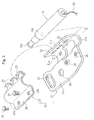
- Fig. 2 is an exploded perspective view showing an attaching clamp serving as an attaching member
- Fig. 3 is a cross-section along III-III line in Fig. 2
- Fig. 4 is an explanatory view showing a sandwiching procedure of the inflator by means of the attaching clamp
- Fig. 5 is an explanatory view of the attaching clamp sandwiching the inflator.
- a seat 1 is provided with a seat cushion 2 and a seat back 3 connected to the seat cushion 2.
- the seat cushion 2 is provided with a cushion pad 2a and a seat frame 2b.
- One end side of an air belt (expansion-type seat belt) 5 is attached to a side face of the seat frame 2b via an attaching clamp 20.
- the air belt 5 includes a shoulder belt portion 6 that is obliquely pulled around a front face side of an upper half of the body of an occupant seated on the seat 1, a lap portion 7, one end side of which is connected to a lower end of the shoulder portion 6 and the other end side of which is connected to the attaching clamp 20, being pulled around a front face side in the vicinity of a waist portion or a lower stomach portion of the occupant in the left and right direction, and a non-expansion type shoulder belt 8 connected to an upper end of the shoulder portion 6.
- the shoulder belt 8 is hung through a shoulder anchor 9 provided at a pillar portion (not shown) of a vehicle body, and the tip end side thereof is capable of being retracted by means of a seat belt retractor (not shown).
- a portion between the shoulder portion 6 and the lap portion 7 is hung through a through-anchor of a tongue (not shown).
- a buckle device (not shown), to which the tongue is connected (latched), is provided at a side of the seat frame 2b opposite to that of the attaching clamp 20.
- Gas is supplied to the lap portion 7 from an inflator 10 attached to the attaching clamp 20.
- the gas supplied from the inflator 10 is also introduced into the shoulder portion 6 via the lap portion 7 in this embodiment.
- the gas may be supplied to the shoulder portion 6 and the lap portion 7 from separate inflators.
- the attaching clamp 20 is rotatably attached to the seat frame 2b in a front-and-back direction of the vehicle body by means of a pivot 11.
- the attaching clamp 20 is composed of a main plate 21 connected to the seat frame 2b and a sub-plate 22 attached to the main plate 21, and the inflator 10 is sandwiched between the main plate 21 and the sub-plate 22.
- the inflator 10 is formed of a straight rod like shape (approximately a cylindrical shape), and a tube like gas-blowing out nozzle 10a protrudes in an extending direction of the axis line from one end (tip end) side thereof in an axis line direction.
- the inflator 10 is configured such that the gas is blown out in the extending direction of the axis line of the gas blowing-out nozzle 10a from the tip end thereof.
- a numeral 10b denotes a harness for power distribution for the inflator 10, which extends from the other end (rear end) of the inflator 10.
- a positioning projection 10c for positioning the inflator 10 to the attaching clamp 20 protrudes from a predetermined position of an outer peripheral surface of the inflator 10, as shown in Fig. 3.
- An inflator holding portion 21 a of the main plate 21 is formed into approximately a half around of a cylindrical shape in a curved manner surrounding approximately a half around of the outer peripheral surface of the inflator 10, as shown in Figs. 4 and 5.
- a one end side 21b in the peripheral direction of the inflator holding portion 21 a is extending in approximately a tangential line direction of the inflator 10; and a hook-portion hooking hole 23 is formed to serve as a hooked portion for a hook portion 28, described later, at the one end side 21b.
- three hook-portion hooking holes 23 are formed at different positions in the axis line direction of the inflator 10.
- An approximately flat shaped base piece portion 21 c is extended from the other end side in a peripheral direction of the inflator holding portion 2 1 a toward approximately a radial direction of the inflator 10. As shown in Fig. 2, the base piece portion 21 c is extended toward a tip end side (the side of the gas blowing-out nozzle 10a) in an axis line direction of the inflator 10 more than the inflator holding portion 21a, and a lap portion insertion hole 24 into which a tip end side of the aforementioned lap portion 7 is inserted is provided along an edge of a tip end side in the extending direction.
- the lap portion insertion hole 24 is extending in a direction intersecting with the axis line of the inflator 10.
- a pivot hole 25 in which the aforementioned pivot 11 is inserted is provided.
- a portion in the base piece portion 21 c, situated at a rear end side of the inflator 10 from the pivot hole 25, is configured to form a portion in which a fastening portion 29, described later, overlaps thereon, and a nut 26 into which a bolt 30 for fastening the fastening portion 29 is screwed is firmly fixed at this portion.
- two nuts 26 are provided in the axis line direction of the inflator 10 at the different positions thereof
- the sub-plate 22 is formed into approximately a half around of a cylindrical shape in a curved manner surrounding an extent of a half around of a remaining outer peripheral surface of the inflator 10, or an extent of a peripheral length slightly shorter than that.
- a hook portion 28 to catch a hook-portion hooking hole 23 protrudes from one end side in a peripheral direction of the sub-plate 22 (a side of the hook-portion hooking hole 23 of the main plate 21) to approximately a radial direction of the inflator 10.
- the hook portion 28 is provided three in number in a positional relation corresponding to each of the hook-portion hooking holes 23.
- a tip end side of each of the hook portions 28 is formed into approximately an L-shape or a J-shape in an extending direction of one end side 21b of the aforementioned inflator holding portion 21 a in a curved manner.
- a lingual-piece like fastening portion 29 is protruding in a manner so as to be in parallel with the base piece portion 21 c toward approximately a radial direction of the inflator 10.
- Two bolt insertion holes 29a are provided in the fastening portion 29 in an overlapping positional relationship with the nuts 26 provided on the base piece portion 21 c.
- a plate thickness T 1 of the sub-plate 22 is configured to be smaller than a plate thickness T 2 of the main plate 21.
- the inflator 10 When the inflator 10 is attached to the attaching clamp 20, firstly, the inflator 10 is fit in the inflator holding portion 21a of the main plate 21, as shown in Fig. 3. At this moment, the positioning projection 10c of the inflator 10 is engaged with the small hole 27 of the bottom face of the inflator holding portion 21a.
- each of the hook portions 28 of the sub-plate 22 is hooked on each of the hook-portion hooking holes 23 of the main plate 21, and the sub-plate 22 is overlapped with the main plate 21 at a side opposite to the inflator 10, in a manner so as to rotate the sub-plate 22 about the hooked portions of the hook-portion hooking hole 23 with the hook portion 28 that serve as a fulcrum, and the fastening portion 29 of the sub-plate 22 is configured to be situated in parallel with the base piece portion 21 c of the main plate 21.
- the bolt 30 is screwed into the nut 26 via the bolt insertion hole 29a of the fastening portion 29, and thus the fastening portion 29 and the base piece portion 21c are fastened.
- the inflator 10 is fixed in a manner sandwiched between the main plate 21 and the sub-plate 22.
- the lap portion 7 of the air belt 5 is connected to the main plate 21 via the aforementioned lap portion insertion hole 24, and a gas introducing duct 7a of the lap portion 7 is connected to the gas blowing-out nozzle 10a of the inflator 10.
- a tip end side of the lap portion 7 is folded back and stitched with itself in a manner so as to surround an upper edge side of the lap portion insertion hole 24 after inserting the tip end side of the lap portion 7 into the lap portion insertion hole 24.
- the lap portion 7 may be connected to the main plate 21 before the inflator 10 is attached to the attaching clamp 20.
- the main plate 21 is disposed at a side face of the seat frame 2b, and the pivot 11 is firmly fixed to the seat frame 2b through the aforementioned pivot hole 25.
- the main plate 21 (attaching clamp 20) is attached to the seat frame 2b, and attaching operation of the inflator 10 to the seat frame 2b is thereby completed.
- the hook portion 28 of the sub-plate 22 is hooked on the hook-portion hooking hole 23 of the main plate 21, and the fastening portion 29 and the base piece portion 21c are fastened with a bolt 30, upon situating the fastening portion 29 of the sub-plate 22 in parallel with the base piece portion 21 c of the main plate 21 in a manner so as to sandwich the inflator 10 between the main plate 21 and the sub-plate 22.
- the sub-plate 22 can be easily fastened on to the main plate 21.
- the plate thickness T 1 of the sub-plate 22 is configured to be smaller than the plate thickness T 2 of the main plate 21.
- the firmness of attaching the inflator 10 is sufficiently high because the main plate 21 is attached to the seat frame 2b.
- the weight of the sub-plate 22 can be aimed at reducing by means of reduction of the plate thickness T 1 of the sub-plate 22. Further, bending process for the sub-plate is performed with ease.
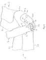
- FIG. 6 shows a side view with an attaching clamp 20A according to a second embodiment mounted to a seat, similar to the view of Fig. 1. However, in Fig. 6 the portion where the attached clamp 20A is mounted is shown in an enlarged manner.
- the seat of Fig. 6 has a seat cushion 2 with a cushion pad 2a and a seat frame 2b.
- the seat of Fig. 6 also has a seat back 3 which is in this case depicted with a seat frame portion 3a and a seat back pad 3b.
- the seat of Fig. 6 further comprises a seat finisher 4 located generally at the area where the seat cushion 2 and the seat back 3 are linked.
- the seat finisher 4 has a portion 4b being equipped with a cover and a cut-out portion 4b where the cover is cut out.
- the attaching clamp 20A of the embodiment shown in Fig. 6 is located at the portion 4b.
- the general structure of the attaching clamp 20A is similar to the structure of the attaching clamp 20 as shown in Figs. 1-5 and in particular in Fig. 2.
- the attaching clamp 20A shown has a main plate and a sub-plate which are fixed together by bolts 30 so as to sandwich an inflator 10 therebetween.
- the attaching clamp 20A also has a lap portion insertion hole 24 which, as can be seen in Fig. 6, is positioned different than in Fig. 2.
- the lap portion insertion hole extends basically perpendicular to the inflator, whereas in Fig. 6 the longitudinal axis of the lap portion insertion hole 24 forms an acute angle with the inflator 10.
- the lap belt 7 can be fixed to the attaching clamp 20A when the attaching clamp is positioned as shown in Fig. 6, i.e. which the longitudinal axis of the inflator 10 basically parallel to the direction in which the seat finisher 4 extends from the seat cushion 2.
- a bent duct 32 is provided extending from the inflator 10 to the lap portion.
- holding portions 31 are provided at the attaching clamp 20A to securely hold the duct 32 in position.
- a hole similar to hole 25 of Fig. 2 is provided, and the attaching clamp 20A can be fixed to the seat with a bolt 34 extending through said hole.
- Bolt 34 may act as a pivot for rotatably mounting the attaching clamp 20A like the pivot 11 of the embodiment of Figs. 1-5.
- cut-outs 33 may be provided in the cover 4a of the seat finisher and the seat frame 2b of the seat cushion 2 in order to guide the lap belt portion 7.
- the hook portion is provided in the sub-plate and the hook portion-hooking hole is provided in the main plate in the aforementioned embodiments, the hook portion may be provided in the main plate and the hook-portion hooking hole may be formed in the sub-plate.
- the present invention is applicable of various inflator attaching structures, such as an inflator attaching structure of an air bag device for preventing the submarine phenomenon from occurring as described in the introductory portion, an inflator attaching structure for use in a side airbag device, or the like.
Landscapes
- Engineering & Computer Science (AREA)
- Mechanical Engineering (AREA)
- Air Bags (AREA)
- Automotive Seat Belt Assembly (AREA)
- Cleaning Of Streets, Tracks, Or Beaches (AREA)
Applications Claiming Priority (1)
| Application Number | Priority Date | Filing Date | Title |
|---|---|---|---|
| JP2005295245A JP4736687B2 (ja) | 2005-10-07 | 2005-10-07 | インフレータ取付構造及びラップアンカ |
Publications (3)
| Publication Number | Publication Date |
|---|---|
| EP1772329A2 true EP1772329A2 (de) | 2007-04-11 |
| EP1772329A3 EP1772329A3 (de) | 2008-06-04 |
| EP1772329B1 EP1772329B1 (de) | 2009-12-02 |
Family
ID=37603428
Family Applications (1)
| Application Number | Title | Priority Date | Filing Date |
|---|---|---|---|
| EP06019250A Expired - Fee Related EP1772329B1 (de) | 2005-10-07 | 2006-09-14 | Haltevorrichtung für einen Gasgenerator und Verankerung für einen Beckengurt |
Country Status (5)
| Country | Link |
|---|---|
| US (1) | US7661697B2 (de) |
| EP (1) | EP1772329B1 (de) |
| JP (1) | JP4736687B2 (de) |
| CN (1) | CN1944113B (de) |
| DE (1) | DE602006010789D1 (de) |
Families Citing this family (30)
| Publication number | Priority date | Publication date | Assignee | Title |
|---|---|---|---|---|
| JP4734933B2 (ja) * | 2004-02-27 | 2011-07-27 | タカタ株式会社 | 車両乗員保護システムおよびインフレータ |
| JP4923529B2 (ja) * | 2005-11-14 | 2012-04-25 | タカタ株式会社 | 乗員拘束装置 |
| JP2007137181A (ja) * | 2005-11-16 | 2007-06-07 | Takata Corp | エアベルト装置 |
| US20080106074A1 (en) * | 2006-11-02 | 2008-05-08 | Key Safety Systems, Inc. | Air Bag Module and Fastener |
| KR100858220B1 (ko) * | 2007-10-22 | 2008-09-10 | 현대모비스 주식회사 | 에어백모듈 |
| JP2009154670A (ja) * | 2007-12-26 | 2009-07-16 | Nippon Plast Co Ltd | インフレータ取付装置及びエアバッグ装置 |
| US7980590B2 (en) * | 2008-03-19 | 2011-07-19 | Amsafe, Inc. | Inflatable personal restraint systems having web-mounted inflators and associated methods of use and manufacture |
| US7862081B2 (en) * | 2008-10-09 | 2011-01-04 | Gm Global Technology Operations, Inc. | Motor vehicle safety restraint system |
| US7905514B2 (en) * | 2008-11-14 | 2011-03-15 | GM Global Technology Operations LLC | Motor vehicle safety restraint system |
| DE102011000052A1 (de) * | 2010-01-08 | 2011-07-28 | TK Holdings, Inc., Mich. | Airbag |
| DE102010052782A1 (de) * | 2010-11-30 | 2012-05-31 | Trw Automotive Gmbh | Fahrzeuginsassenrückhaltesystem für ein Fahrzeug und Dichtungselement |
| US8439398B2 (en) | 2011-07-29 | 2013-05-14 | Amsafe, Inc. | Inflator connectors for inflatable personal restraints and associated systems and methods |
| US9511866B2 (en) | 2012-03-19 | 2016-12-06 | Amsafe, Inc. | Structure mounted airbag assemblies and associated systems and methods |
| US8523220B1 (en) | 2012-03-19 | 2013-09-03 | Amsafe, Inc. | Structure mounted airbag assemblies and associated systems and methods |
| US8651519B2 (en) * | 2012-04-09 | 2014-02-18 | Autoliv Asp, Inc. | Seatbelt anchor airbag |
| KR101614492B1 (ko) * | 2013-05-06 | 2016-04-22 | 아우토리브 디벨롭먼트 아베 | 차량용 벨트 백 |
| KR101560543B1 (ko) | 2013-05-06 | 2015-10-15 | 아우토리브 디벨롭먼트 아베 | 차량용 벨트 백의 앙카 조립체 |
| JP6113048B2 (ja) | 2013-10-23 | 2017-04-12 | 株式会社東海理化電機製作所 | シートベルト装置 |
| EP3170703B1 (de) * | 2014-07-14 | 2019-03-13 | TS Tech Co., Ltd. | Seitenairbagvorrichtung |
| US9352839B2 (en) | 2014-10-02 | 2016-05-31 | Amsafe, Inc. | Active positioning airbag assembly and associated systems and methods |
| US9944245B2 (en) | 2015-03-28 | 2018-04-17 | Amsafe, Inc. | Extending pass-through airbag occupant restraint systems, and associated systems and methods |
| EP3283336B1 (de) | 2015-04-11 | 2019-11-20 | AmSafe, Inc. | Aktives entlüftungssystem für airbag |
| DE102015006898A1 (de) * | 2015-06-03 | 2016-12-22 | Trw Airbag Systems Gmbh | Baugruppe eines Fahrzeugsicherheitssystems, Fahrzeugsicherheitssystem, Fahrzeugsicherheitseinrichtung und Verfahren zum Herstellen einer Baugruppe eines Fahrzeugsicherheitssystems |
| US10604259B2 (en) | 2016-01-20 | 2020-03-31 | Amsafe, Inc. | Occupant restraint systems having extending restraints, and associated systems and methods |
| US11485311B2 (en) | 2017-11-09 | 2022-11-01 | Ts Tech Co., Ltd. | Side airbag device and method for manufacturing same |
| US11414039B2 (en) * | 2017-11-09 | 2022-08-16 | Honda Motor Co., Ltd. | Side airbag device |
| GB2579668B (en) * | 2018-12-12 | 2021-01-13 | Ford Global Tech Llc | An airbag |
| JP7115411B2 (ja) * | 2019-04-23 | 2022-08-09 | 豊田合成株式会社 | 膝保護用エアバッグ装置 |
| JP7124810B2 (ja) * | 2019-08-26 | 2022-08-24 | 豊田合成株式会社 | サイドエアバッグ装置 |
| US11292425B2 (en) | 2019-11-19 | 2022-04-05 | Schroth Safety Products Llc | Safety device |
Citations (5)
| Publication number | Priority date | Publication date | Assignee | Title |
|---|---|---|---|---|
| US5899485A (en) | 1996-12-10 | 1999-05-04 | Takata, Inc. | Air bag module with simplified manifold |
| JP2001213256A (ja) | 2000-02-07 | 2001-08-07 | Honda Motor Co Ltd | エアベルト装置 |
| EP1216895A2 (de) | 2000-12-22 | 2002-06-26 | TAKATA (EUROPE) VEHICLE SAFETY TECHNOLOGY GmbH | Haltevorrichtung |
| JP2003312439A (ja) | 2002-04-23 | 2003-11-06 | Honda Motor Co Ltd | エアベルト装置 |
| EP1550588A2 (de) | 2003-12-24 | 2005-07-06 | Toyoda Gosei Co., Ltd. | Knieschutzeinrichtung |
Family Cites Families (22)
| Publication number | Priority date | Publication date | Assignee | Title |
|---|---|---|---|---|
| BE756451A (fr) * | 1970-02-21 | 1971-03-01 | Rutzki Edith | Ceinture de securite |
| US3841654A (en) * | 1972-09-21 | 1974-10-15 | Allied Chem | Vehicle safety system |
| US3970329A (en) * | 1973-01-10 | 1976-07-20 | Allied Chemical Corporation | Inflatable band restraint stitching |
| US3866940A (en) * | 1973-01-11 | 1975-02-18 | Allied Chem | Differentially inflatable restraining band for vehicles |
| JPS63258239A (ja) * | 1987-04-14 | 1988-10-25 | Mitsuharu Yamaguchi | 膨張機能を有する人体緊締保護方法 |
| JP2707923B2 (ja) * | 1992-08-04 | 1998-02-04 | トヨタ自動車株式会社 | サイドエアバッグ装置の衝突センサ取付構造 |
| JP3666963B2 (ja) * | 1995-12-22 | 2005-06-29 | オートリブ デベロップメント アクテボラゲット | エアバッグ装置 |
| JP3285129B2 (ja) | 1997-01-31 | 2002-05-27 | ジョンソン コントロールズ オートモーティブ システムズ株式会社 | 車両用シート |
| US6109647A (en) * | 1997-12-15 | 2000-08-29 | Honda Giken Kogyo Kabushiki Kaisha | Seat-occupant restraining apparatus |
| DE69910304T2 (de) * | 1998-06-09 | 2004-06-24 | Takata Corp. | Aufblasbare Sicherheitsgurtvorrichtung |
| JP3809736B2 (ja) * | 1998-12-24 | 2006-08-16 | タカタ株式会社 | エアベルト装置 |
| JP2000225913A (ja) * | 1999-02-08 | 2000-08-15 | Takata Corp | エアバッグ装置とインフレータとの連結構造 |
| US6406058B1 (en) * | 1999-11-18 | 2002-06-18 | Universal Propulsion Co., Inc. | Inflatable safety restraint system |
| US6305710B1 (en) * | 2000-02-24 | 2001-10-23 | Autoliv Asp, Inc. | Inflatable knee bolster module assembly |
| US6471243B1 (en) * | 2000-09-07 | 2002-10-29 | Trw Vehicle Safety Systems Inc. | Inflation mechanism for inflatable seat belt |
| JP3912195B2 (ja) | 2002-06-12 | 2007-05-09 | タカタ株式会社 | 乗員保護装置 |
| JP4122904B2 (ja) | 2002-09-05 | 2008-07-23 | タカタ株式会社 | 乗員保護装置 |
| JP2004106651A (ja) | 2002-09-17 | 2004-04-08 | Takata Corp | 乗員保護装置 |
| JP4053463B2 (ja) * | 2003-05-26 | 2008-02-27 | オートリブ株式会社 | エアバッグ付きシートベルト装置 |
| JP2005231504A (ja) | 2004-02-19 | 2005-09-02 | Takata Corp | 乗員保護装置 |
| JP2006117219A (ja) | 2004-02-20 | 2006-05-11 | Takata Corp | 乗員保護装置 |
| JP2005239055A (ja) * | 2004-02-27 | 2005-09-08 | Takata Corp | 乗員保護装置 |
-
2005
- 2005-10-07 JP JP2005295245A patent/JP4736687B2/ja not_active Expired - Fee Related
-
2006
- 2006-09-14 DE DE602006010789T patent/DE602006010789D1/de active Active
- 2006-09-14 EP EP06019250A patent/EP1772329B1/de not_active Expired - Fee Related
- 2006-09-29 US US11/529,429 patent/US7661697B2/en not_active Expired - Fee Related
- 2006-09-30 CN CN2006101420119A patent/CN1944113B/zh not_active Expired - Fee Related
Patent Citations (5)
| Publication number | Priority date | Publication date | Assignee | Title |
|---|---|---|---|---|
| US5899485A (en) | 1996-12-10 | 1999-05-04 | Takata, Inc. | Air bag module with simplified manifold |
| JP2001213256A (ja) | 2000-02-07 | 2001-08-07 | Honda Motor Co Ltd | エアベルト装置 |
| EP1216895A2 (de) | 2000-12-22 | 2002-06-26 | TAKATA (EUROPE) VEHICLE SAFETY TECHNOLOGY GmbH | Haltevorrichtung |
| JP2003312439A (ja) | 2002-04-23 | 2003-11-06 | Honda Motor Co Ltd | エアベルト装置 |
| EP1550588A2 (de) | 2003-12-24 | 2005-07-06 | Toyoda Gosei Co., Ltd. | Knieschutzeinrichtung |
Also Published As
| Publication number | Publication date |
|---|---|
| JP2007099224A (ja) | 2007-04-19 |
| US20070080526A1 (en) | 2007-04-12 |
| CN1944113A (zh) | 2007-04-11 |
| JP4736687B2 (ja) | 2011-07-27 |
| US20090230662A9 (en) | 2009-09-17 |
| CN1944113B (zh) | 2010-11-17 |
| US7661697B2 (en) | 2010-02-16 |
| DE602006010789D1 (de) | 2010-01-14 |
| EP1772329A3 (de) | 2008-06-04 |
| EP1772329B1 (de) | 2009-12-02 |
Similar Documents
| Publication | Publication Date | Title |
|---|---|---|
| EP1772329B1 (de) | Haltevorrichtung für einen Gasgenerator und Verankerung für einen Beckengurt | |
| US7735855B2 (en) | Bracket for securing side airbag for automotive vehicle | |
| US7789414B2 (en) | Gas generator assembly mounting mechanism | |
| US7862075B2 (en) | Bracket for use in curtain airbag and curtain airbag apparatus | |
| US11548468B2 (en) | Occupant protection system | |
| EP2559598B1 (de) | Luftgurtvorrichtung | |
| US7874582B2 (en) | Child seat installation structure with seat belt having expandable portion | |
| EP1422104A1 (de) | Insassenschutzeinrichtung. | |
| US8840137B2 (en) | Belt integrated airbag | |
| JP2017218134A (ja) | エアバッグ装置 | |
| US20220258688A1 (en) | Side airbag device | |
| JP4923531B2 (ja) | エアベルト装置 | |
| JP2006199198A (ja) | ラップアウタプリテンショナーの配設構造 | |
| JP6499096B2 (ja) | 乗員保護装置 | |
| JP6772659B2 (ja) | 乗員拘束装置 | |
| CN111002942B (zh) | 侧安全气囊装置 | |
| JP2007090903A (ja) | シートベルト装置 | |
| JP6825417B2 (ja) | 車両用シートベルトガイド構造 | |
| JP5495691B2 (ja) | 車両用シート装置 | |
| JPH07323800A (ja) | エアバッグドア用ストラップ取付構造 | |
| JP2024007694A (ja) | 力布の固定構造およびこれを備えた車両用シート | |
| JP2023118011A (ja) | 乗員保護装置 | |
| CN116279271A (zh) | 气囊装置 | |
| JP2021054252A (ja) | 乗員保護装置 | |
| JP2023120836A (ja) | 乗員保護装置 |
Legal Events
| Date | Code | Title | Description |
|---|---|---|---|
| PUAI | Public reference made under article 153(3) epc to a published international application that has entered the european phase |
Free format text: ORIGINAL CODE: 0009012 |
|
| AK | Designated contracting states |
Kind code of ref document: A2 Designated state(s): AT BE BG CH CY CZ DE DK EE ES FI FR GB GR HU IE IS IT LI LT LU LV MC NL PL PT RO SE SI SK TR |
|
| AX | Request for extension of the european patent |
Extension state: AL BA HR MK YU |
|
| PUAL | Search report despatched |
Free format text: ORIGINAL CODE: 0009013 |
|
| AK | Designated contracting states |
Kind code of ref document: A3 Designated state(s): AT BE BG CH CY CZ DE DK EE ES FI FR GB GR HU IE IS IT LI LT LU LV MC NL PL PT RO SE SI SK TR |
|
| AX | Request for extension of the european patent |
Extension state: AL BA HR MK RS |
|
| 17P | Request for examination filed |
Effective date: 20080904 |
|
| 17Q | First examination report despatched |
Effective date: 20081029 |
|
| AKX | Designation fees paid |
Designated state(s): DE GB |
|
| GRAP | Despatch of communication of intention to grant a patent |
Free format text: ORIGINAL CODE: EPIDOSNIGR1 |
|
| GRAS | Grant fee paid |
Free format text: ORIGINAL CODE: EPIDOSNIGR3 |
|
| GRAA | (expected) grant |
Free format text: ORIGINAL CODE: 0009210 |
|
| AK | Designated contracting states |
Kind code of ref document: B1 Designated state(s): DE GB |
|
| REG | Reference to a national code |
Ref country code: GB Ref legal event code: FG4D |
|
| REF | Corresponds to: |
Ref document number: 602006010789 Country of ref document: DE Date of ref document: 20100114 Kind code of ref document: P |
|
| PLBE | No opposition filed within time limit |
Free format text: ORIGINAL CODE: 0009261 |
|
| STAA | Information on the status of an ep patent application or granted ep patent |
Free format text: STATUS: NO OPPOSITION FILED WITHIN TIME LIMIT |
|
| 26N | No opposition filed |
Effective date: 20100903 |
|
| PGFP | Annual fee paid to national office [announced via postgrant information from national office to epo] |
Ref country code: GB Payment date: 20120912 Year of fee payment: 7 |
|
| GBPC | Gb: european patent ceased through non-payment of renewal fee |
Effective date: 20130914 |
|
| PG25 | Lapsed in a contracting state [announced via postgrant information from national office to epo] |
Ref country code: GB Free format text: LAPSE BECAUSE OF NON-PAYMENT OF DUE FEES Effective date: 20130914 |
|
| REG | Reference to a national code |
Ref country code: DE Ref legal event code: R082 Ref document number: 602006010789 Country of ref document: DE Representative=s name: KRAUS & WEISERT PATENTANWAELTE PARTGMBB, DE Ref country code: DE Ref legal event code: R081 Ref document number: 602006010789 Country of ref document: DE Owner name: JOYSON SAFETY SYSTEMS JAPAN K.K., JP Free format text: FORMER OWNER: TAKATA CORP., TOKIO/TOKYO, JP |
|
| PGFP | Annual fee paid to national office [announced via postgrant information from national office to epo] |
Ref country code: DE Payment date: 20180920 Year of fee payment: 13 |
|
| REG | Reference to a national code |
Ref country code: DE Ref legal event code: R119 Ref document number: 602006010789 Country of ref document: DE |
|
| PG25 | Lapsed in a contracting state [announced via postgrant information from national office to epo] |
Ref country code: DE Free format text: LAPSE BECAUSE OF NON-PAYMENT OF DUE FEES Effective date: 20200401 |