EP1686768A2 - Klappbares Telefon mit rotierenden Anzeige - Google Patents
Klappbares Telefon mit rotierenden Anzeige Download PDFInfo
- Publication number
- EP1686768A2 EP1686768A2 EP06001253A EP06001253A EP1686768A2 EP 1686768 A2 EP1686768 A2 EP 1686768A2 EP 06001253 A EP06001253 A EP 06001253A EP 06001253 A EP06001253 A EP 06001253A EP 1686768 A2 EP1686768 A2 EP 1686768A2
- Authority
- EP
- European Patent Office
- Prior art keywords
- liquid crystal
- crystal display
- display part
- housing
- cellular phone
- Prior art date
- Legal status (The legal status is an assumption and is not a legal conclusion. Google has not performed a legal analysis and makes no representation as to the accuracy of the status listed.)
- Withdrawn
Links
Images


Classifications
-
- H—ELECTRICITY
- H04—ELECTRIC COMMUNICATION TECHNIQUE
- H04B—TRANSMISSION
- H04B1/00—Details of transmission systems, not covered by a single one of groups H04B3/00 - H04B13/00; Details of transmission systems not characterised by the medium used for transmission
- H04B1/38—Transceivers, i.e. devices in which transmitter and receiver form a structural unit and in which at least one part is used for functions of transmitting and receiving
- H04B1/40—Circuits
-
- H—ELECTRICITY
- H04—ELECTRIC COMMUNICATION TECHNIQUE
- H04M—TELEPHONIC COMMUNICATION
- H04M1/00—Substation equipment, e.g. for use by subscribers
- H04M1/02—Constructional features of telephone sets
- H04M1/0202—Portable telephone sets, e.g. cordless phones, mobile phones or bar type handsets
- H04M1/0206—Portable telephones comprising a plurality of mechanically joined movable body parts, e.g. hinged housings
- H04M1/0247—Portable telephones comprising a plurality of mechanically joined movable body parts, e.g. hinged housings comprising more than two body parts
-
- G—PHYSICS
- G06—COMPUTING; CALCULATING OR COUNTING
- G06F—ELECTRIC DIGITAL DATA PROCESSING
- G06F1/00—Details not covered by groups G06F3/00 - G06F13/00 and G06F21/00
- G06F1/16—Constructional details or arrangements
- G06F1/1613—Constructional details or arrangements for portable computers
- G06F1/1615—Constructional details or arrangements for portable computers with several enclosures having relative motions, each enclosure supporting at least one I/O or computing function
- G06F1/1616—Constructional details or arrangements for portable computers with several enclosures having relative motions, each enclosure supporting at least one I/O or computing function with folding flat displays, e.g. laptop computers or notebooks having a clamshell configuration, with body parts pivoting to an open position around an axis parallel to the plane they define in closed position
-
- G—PHYSICS
- G06—COMPUTING; CALCULATING OR COUNTING
- G06F—ELECTRIC DIGITAL DATA PROCESSING
- G06F1/00—Details not covered by groups G06F3/00 - G06F13/00 and G06F21/00
- G06F1/16—Constructional details or arrangements
- G06F1/1613—Constructional details or arrangements for portable computers
- G06F1/1615—Constructional details or arrangements for portable computers with several enclosures having relative motions, each enclosure supporting at least one I/O or computing function
- G06F1/1622—Constructional details or arrangements for portable computers with several enclosures having relative motions, each enclosure supporting at least one I/O or computing function with enclosures rotating around an axis perpendicular to the plane they define or with ball-joint coupling, e.g. PDA with display enclosure orientation changeable between portrait and landscape by rotation with respect to a coplanar body enclosure
-
- H—ELECTRICITY
- H04—ELECTRIC COMMUNICATION TECHNIQUE
- H04M—TELEPHONIC COMMUNICATION
- H04M1/00—Substation equipment, e.g. for use by subscribers
- H04M1/02—Constructional features of telephone sets
- H04M1/0202—Portable telephone sets, e.g. cordless phones, mobile phones or bar type handsets
- H04M1/0206—Portable telephones comprising a plurality of mechanically joined movable body parts, e.g. hinged housings
- H04M1/0208—Portable telephones comprising a plurality of mechanically joined movable body parts, e.g. hinged housings characterized by the relative motions of the body parts
- H04M1/0214—Foldable telephones, i.e. with body parts pivoting to an open position around an axis parallel to the plane they define in closed position
-
- H—ELECTRICITY
- H04—ELECTRIC COMMUNICATION TECHNIQUE
- H04M—TELEPHONIC COMMUNICATION
- H04M1/00—Substation equipment, e.g. for use by subscribers
- H04M1/02—Constructional features of telephone sets
- H04M1/0202—Portable telephone sets, e.g. cordless phones, mobile phones or bar type handsets
- H04M1/0206—Portable telephones comprising a plurality of mechanically joined movable body parts, e.g. hinged housings
- H04M1/0208—Portable telephones comprising a plurality of mechanically joined movable body parts, e.g. hinged housings characterized by the relative motions of the body parts
- H04M1/0225—Rotatable telephones, i.e. the body parts pivoting to an open position around an axis perpendicular to the plane they define in closed position
- H04M1/0227—Rotatable in one plane, i.e. using a one degree of freedom hinge
-
- H—ELECTRICITY
- H04—ELECTRIC COMMUNICATION TECHNIQUE
- H04M—TELEPHONIC COMMUNICATION
- H04M1/00—Substation equipment, e.g. for use by subscribers
- H04M1/02—Constructional features of telephone sets
- H04M1/0202—Portable telephone sets, e.g. cordless phones, mobile phones or bar type handsets
- H04M1/0206—Portable telephones comprising a plurality of mechanically joined movable body parts, e.g. hinged housings
- H04M1/0208—Portable telephones comprising a plurality of mechanically joined movable body parts, e.g. hinged housings characterized by the relative motions of the body parts
- H04M1/0225—Rotatable telephones, i.e. the body parts pivoting to an open position around an axis perpendicular to the plane they define in closed position
- H04M1/0233—Including a rotatable display body part
-
- H—ELECTRICITY
- H04—ELECTRIC COMMUNICATION TECHNIQUE
- H04M—TELEPHONIC COMMUNICATION
- H04M1/00—Substation equipment, e.g. for use by subscribers
- H04M1/02—Constructional features of telephone sets
- H04M1/0202—Portable telephone sets, e.g. cordless phones, mobile phones or bar type handsets
- H04M1/0206—Portable telephones comprising a plurality of mechanically joined movable body parts, e.g. hinged housings
- H04M1/0208—Portable telephones comprising a plurality of mechanically joined movable body parts, e.g. hinged housings characterized by the relative motions of the body parts
- H04M1/0235—Slidable or telescopic telephones, i.e. with a relative translation movement of the body parts; Telephones using a combination of translation and other relative motions of the body parts
- H04M1/0237—Sliding mechanism with one degree of freedom
-
- H—ELECTRICITY
- H04—ELECTRIC COMMUNICATION TECHNIQUE
- H04M—TELEPHONIC COMMUNICATION
- H04M1/00—Substation equipment, e.g. for use by subscribers
- H04M1/02—Constructional features of telephone sets
- H04M1/0202—Portable telephone sets, e.g. cordless phones, mobile phones or bar type handsets
- H04M1/026—Details of the structure or mounting of specific components
- H04M1/0266—Details of the structure or mounting of specific components for a display module assembly
Definitions
- the present invention relates to a folding cellular phone, particularly to a folding cellular phone in which a liquid crystal display part is supported to be able to change the orientation between landscape and portrait.
- cellular phones are provided with various capabilities in addition to the communication function, such as e-mail transmission/reception, digital camera shooting, recording/reproducing, television reception, scheduling and so on.
- the chief function of the cellular phone is making and receiving calls.
- importance has been placed on downsizing and weight reduction.
- the cellular phone is vertically oriented and reduced in width.
- the landscape image is displayed full on the portrait display without scaling down.
- the liquid crystal display part and an operation part of the folding cellular phone come into sight when the cellular phone is opened.
- the operation part is also rotated 90 degrees. It is troublesome and difficult for the user to do input with the operation keys in such an unusual state.
- Japanese Unexamined Patent Publication No. 2001-156893 discloses a folding cellular phone including a liquid crystal display part which is supported on a first housing such that the orientation thereof is changeable from portrait to landscape while the cellular phone itself is held in the portrait orientation.
- the liquid crystal display part of the folding cellular phone is supported by a support shaft arranged at a center portion thereof to extend vertical to the liquid crystal display part such that the liquid crystal display part is rotated 90 degrees about the support shaft.
- the bottom side of the liquid crystal display part In order to rotate the liquid crystal display part without contacting a hinge for connecting a first housing and a second housing in a pivotable manner to open/close the phone or a bulge formed below the first housing attached with the liquid crystal display part while preventing an increase in size and thickness of the cellular phone, the bottom side of the liquid crystal display part needs to be rounded to form an arc corresponding to the circumference of a circle having the support shaft as the center. In such a case, the liquid crystal display part cannot be enlarged.
- Japanese Unexamined Patent Publication No. 2003-319043 discloses a folding cellular phone including a support mechanism for supporting the liquid crystal display part on a first housing in a slidable and rotatable manner.
- the liquid crystal display part of the folding cellular phone first slides in the vertical direction and then rotates about a support shaft arranged at a center portion of the liquid crystal display part. Therefore, the liquid crystal display part does not contact the hinge or the bulge provided at the bottom side of the first housing. Thus, the liquid crystal display part is enlarged.
- Japanese Unexamined Patent Publication No. 2004-78073 discloses a support mechanism for a liquid crystal display device which makes it possible to change the orientation of the liquid crystal display part between portrait and landscape.
- digital terrestrial television broadcasting will begin in earnest. Unlike the conventional analog television broadcasting, the digital terrestrial television broadcasting provides so-called interactive services. For example, people can take part in a quiz show, do shopping or complete payment to a bank account through a television set.
- the cellular phone is configured to receive the digital terrestrial television broadcasting, the user needs to operate the keys looking at an image on the display screen.
- television images are landscape-oriented. Therefore, in order to see the landscape television image as large as possible on the small liquid crystal display of the cellular phone, the liquid crystal display needs to be oriented landscape.
- the cellular phone according to Japanese Unexamined Patent Publication No. 2003-319043 requires two kinds of movements, i.e., slide and rotation, to change the orientation. These movements cannot be achieved by a single hand, thereby complicating the operation.
- the liquid crystal display device according to Japanese Unexamined Patent Publication No. 2004-78073 is not required to reduce the size and weight as strictly as the cellular phone is.
- the liquid crystal display part of thereof is not so often changed between portrait and landscape orientation. Therefore, the switching mechanism is complicated and the operation thereof is also complicated.
- the present invention has been achieved in view of the above-described problems.
- the present invention has added a twist to the support mechanism of the liquid crystal display part of the cellular phone to achieve an object of the present invention, i.e., to increase the size of the liquid crystal display part without increasing the size of the cellular phone itself and allow a user to change the orientation of the liquid crystal display part easily between portrait and landscape so that the user can handle the operation part easily looking at the liquid crystal display oriented portrait or landscape.
- the orientation of the liquid crystal display part is changed between portrait and landscape while a bottom corner of the liquid crystal display part moves along the hinge.
- the present invention provides a folding cellular phone including a first housing provided with a liquid crystal display part on the surface thereof, a second housing including an operation part formed on the surface thereof and a hinge for connecting the first housing and the second housing in a pivotable manner to open/close the folding cellular phone.
- the liquid crystal display part is supported on the first housing by a support mechanism such that the orientation of the liquid crystal display part is changeable between portrait and landscape and the support mechanism is configured to support and guide the liquid crystal display part such that a bottom corner of the liquid crystal display part moves along the hinge when the orientation of the liquid crystal display part is changed between portrait and landscape.
- the liquid crystal display part is used in the portrait orientation when the main functions of the cellular phone such as making/receiving calls or sending/receiving e-mails are used.
- the liquid crystal display part is changed to the landscape orientation so that a landscape image is displayed full on the screen and the user does input with the operation keys of the operation part kept in the usual portrait orientation.
- the user operates the liquid crystal display part supported on the first housing.
- the support mechanism guides the liquid crystal display part such that a bottom corner of the liquid crystal display part moves along the hinge. Specifically, as the liquid crystal display part moves while a certain clearance is kept from the hinge, the liquid crystal display part does not contact the hinge or the bulge formed below the first housing even if the bottom side of the liquid crystal display part is not rounded.
- the horizontal center of the portrait- or landscape-oriented liquid crystal display part is positioned substantially at the horizontal center of the first housing.
- the liquid crystal display part when a conventional support shaft for supporting the liquid crystal display part on the first housing is provided at a center portion of the liquid crystal display part and the horizontal center of the landscape-oriented liquid crystal display part is required to be positioned substantially at the horizontal center of the first housing, the liquid crystal display part must be reduced in length from the top end in accordance with the bottom end which has been worked for preventing the interference of the hinge or the bulge. As a result, the liquid crystal display part is reduced in size.
- the support mechanism guides the liquid crystal display part such that the bottom corner thereof moves along the hinge upon changing the orientation to portrait or landscape. Therefore, there is no need of providing the conventional support shaft at the center portion of the liquid crystal display part.
- the horizontal center of the liquid crystal display part is positioned substantially at the horizontal center of the first housing, i.e., the horizontal center of the operation part.
- the support mechanism is a cam.
- the liquid crystal display part is surely guided such that the bottom corner thereof moves along the hinge.
- the cam is configured to support and guide the liquid crystal display part such that the bottom corner of the liquid crystal display part moves along the hinge to draw a linear locus when the orientation of the liquid crystal display part is changed between portrait and landscape and the liquid crystal display part has a linear side which comes to the bottom in the portrait orientation.
- the liquid crystal display part As the liquid crystal display part is guided by the cam to change the orientation such that the bottom corner of the liquid crystal display part moves along the hinge to draw a linear locus, the liquid crystal display part does not contact the hinge even if the liquid crystal display part has the linear bottom side.
- the cam includes a horizontal guide groove which is formed in the first housing and extends in the horizontal direction in the form of an upward convex arc, a vertical guide groove which is formed in the first housing to extend straight in the vertical direction, a first guide pin which is arranged on the rear surface of the liquid crystal display part to slidably engage with the horizontal guide groove and a second guide pin which is arranged on the rear surface of the liquid crystal display part to slidably engage with the vertical guide groove.
- the first guide pin of the liquid crystal display part is engaged with and slides on the horizontal guide groove, and at the same time, the second guide pin of the liquid crystal display part is engaged with and slides on the vertical guide groove. According to the movement restriction by the cam, the liquid crystal display part is changed between portrait and landscape orientation while the bottom corner of the liquid crystal display part moves along the hinge.
- the cam includes an elastic member for biasing the liquid crystal display part to change the orientation at least to portrait or landscape.
- the elastic member assists the liquid crystal display part to change the orientation from portrait to landscape, landscape to portrait or in both ways.
- the elastic member is a torsion coil spring which is fixed to the first guide pin at one end and to the first housing at the other end.
- the elastic member is achieved by a simple and hard-to-break structure.
- a cable housing bulging toward the first housing is formed on a portion of the rear surface of the liquid crystal display part facing the vertical guide groove and an electric cable for electrically connecting the liquid crystal display part and the first housing is arranged in the cable housing to be slightly inclined with respect to the rear surface of the liquid crystal display part.
- the electric cable When the liquid crystal display part is supported on the first housing such that the orientation is changeable between portrait and landscape, the electric cable generally arranged to pass in the vertical direction to the rear surface of the liquid crystal display part in a through hole formed in the support shaft for supporting the liquid crystal display part on the first housing. Therefore, the electric cable is folded over near the through hole, thereby increasing the total thickness of the first housing and the liquid crystal display part more than twice the diameter of the electric cable.
- the electric cable is arranged to be slightly inclined with respect to the rear surface of the liquid crystal display part in the cable housing bulging toward the first housing. Therefore, the electric cable is connected to the liquid crystal display part without a need of folding the electric cable near the cable housing and the total thickness of the first housing and the liquid crystal display part is not increased more than twice the outer diameter of the electric cable.
- a through hole is formed in the axial center of the second guide pin and the electric cable for electrically connecting the liquid crystal display part and the first housing passes through the through hole in the second guide pin.
- the electric cable passes through the second guide pin which moves the least when the liquid crystal display part is changed between portrait and landscape orientation, the electric cable moves less upon changing the orientation.
- horizontal guide groove, vertical guide groove, first guide pin and second guide pin are assembled into a unit.
- the first and second guide pins are precisely arranged in the guide grooves and the cam is easily attached to the first housing.
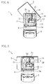
- FIG. 1 is an oblique view illustrating a folding cellular phone according to an embodiment of the present invention in a closed state.
- FIG. 2 is an oblique view illustrating the folding cellular phone in an opened state and a liquid crystal display part in the portrait orientation.
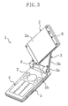
- FIG. 3 is an oblique view illustrating the folding cellular phone in a state where the liquid crystal display part is changing to the portrait or landscape orientation.
- FIG. 4 is an oblique view illustrating the folding cellular phone in the opened state and the liquid crystal display part in the landscape orientation.
- the folding cellular phone 1 of the present embodiment includes a first housing 3 provided with a liquid crystal display part 2 on the surface thereof, a second housing 5 including an operation part 4 formed on the surface thereof and a hinge 6 for connecting the first and second housings 3 and 5 in a pivotable manner to open/close the folding cellular phone 1.
- the first and second housings 3 and 5 are electrically connected by a connecting means (not shown) in the hinge 6.
- the folding cellular phone 1 is changeable between the closed state shown in FIG. 1 and the opened state shown in FIG. 2.
- the operation part 4 of the second housing 5 includes a plurality of operation keys 7.
- the operation keys 7 are arranged such that the user can do input smoothly when he/she holds the folding cellular phone 1 in the portrait orientation and provided with markings on their surfaces.
- Various functions of the folding cellular phone 1 are available through the operation with the operation keys 7.
- the second housing 5 is also provided with a microphone for communication (not shown).
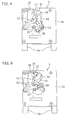
- the first housing 3 is provided with a cam 10 serving as a support mechanism for supporting the liquid crystal display part 2 in the form of an almost rectangular plate such that the orientation of the liquid crystal display part 2 is changeable between portrait and landscape.
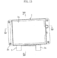
- the first housing 3 includes a first housing body 3b provided with bosses 3a at both ends of the bottom side for receiving a shaft (not shown) of the hinge 6 and a rear cover 3c (omitted for explanation in FIGS. 2 to 7) in the form of a rectangular dish for covering the first housing body 3b.
- the liquid crystal display part 2 has a linear side which comes to the bottom when the liquid crystal display part 2 is portrait-oriented.
- a rectangular liquid crystal display 2a is provided on the almost entire surface of the liquid crystal display part 2.
- a speaker 8 for communication is provided at an end portion of the liquid crystal display part 2 which comes to the top when the liquid crystal display part 2 is portrait-oriented.
- the corners of the liquid crystal display part 2, including a bottom corner 2b, are chamfered for design and safety purposes.
- a cam opening 3d is provided in an upper left portion of the front surface of the first housing 3 (the surface facing the liquid crystal display part 2). Below the cam opening 3d, a rear liquid crystal display 11 is provided for indicating time or other information when the cellular phone is closed.
- the liquid crystal display part 2 and the operation part 4 come into sight when the cellular phone 1 is opened. Therefore, whether the liquid crystal display part 2 is portrait- or landscape-oriented, the user handles the operation keys 7 of the operation part 4 in the portrait orientation looking at the liquid crystal display 2a of the liquid crystal display part 2.
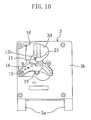
- the cam 10 includes a horizontal guide groove 12 which is formed in the first housing 3 to extend in the horizontal direction in the form of an upward convex arc, a vertical guide groove 14 which is formed in the first housing 3 to extend straight in the vertical direction, a first guide pin 13 which is arranged on the rear surface of the liquid crystal display part 2 to slidably engage with the horizontal guide groove 12 and a second guide pin 15 which is arranged on the rear surface of the liquid crystal display part 2 to slidably engage with the vertical guide groove 14.
- the horizontal guide groove 12 and the vertical guide groove 14 are formed in a metallic guide plate 16 attached to the first housing 3.
- the vertical guide groove 12 is an opening in the form of an upward convex arc and the center thereof is shifted to the right when viewed from the back of the folding cellular phone 1.
- the vertical guide groove 14 is a linear opening which is formed above the uppermost part of the horizontal guide groove 12 to extend in the vertical direction.
- steps 12a and 14a are formed at the peripheries of the guide grooves 12 and 14, respectively.
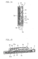
- the guide plate 16 is positioned in the middle of the thickness of the first housing 3 as shown in FIGS. 14 and 15 and fixed to the first housing body 3b with screws (not shown) inserted in through holes 16a.
- the second guide pin 15 corresponding to a conventional support shaft extending vertical to the liquid crystal display part 2 is off-centered to be positioned at an upper right portion of the first housing 3 when viewed from the back of the folding cellular phone 1.
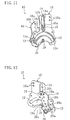
- the linking member 18 has a plate-shaped mounting part 18b provided with through holes 18a for fixing or positioning the linking member 18 to or at the rear surface of the liquid crystal display part 2 and a tip portion 18c continuously extending from the mounting part 18b in the form of L when viewed from the side.
- the first guide pin 13 is provided at an end portion of the linking member 18, i.e., an end portion of the mounting part 18b, to extend vertical to the first housing 3.
- the second guide pin 15 is provided at the other end portion of the linking member 18, i.e., an end portion of the tip portion 18c, to extend vertical to the first housing 3.
- the tips of the guide pins 13 and 15 are tapered to such a degree that the tips are inserted into the guide grooves 12 and 14.
- the tapered tips of the guide pins 13 and 15 are inserted into the guide grooves 12 and 14 and then riveted to form ring-shaped heads 13a and 15a.
- the ring-shaped heads 13a and 15a slide on the steps 12a and 14a, respectively.
- a pin 19 for fixing a spring is formed at a bottom portion of the guide plate 16 to extend vertical toward the liquid crystal display part 2.
- a torsion coil spring 20 as an elastic member is fixed to the pin 19. Both ends 20a and 20b of the torsion coil spring 20 are coiled in a loop. The end 20a is rotatably fitted around the first guide pin 13 and the end 20b is rotatably fitted around the pin 19. Accordingly, the torsion coil spring 20 is supported to move from side to side on the pin 19.
- the elastic force of the torsion coil spring 20 biases the liquid crystal display part 2 to change the orientation from portrait to landscape and vice versa. Specifically, when the first guide pin 13 comes to the closest position to the pin 19 as in the state shown in FIG.
- the guide grooves 12 and 14, the first and second guide pins 13 and 15 and the torsion coil spring 20 is assembled into a unit and this cam unit 10 is attached to the first housing 3.
- a cable housing 22 for passing an electric cable 21 therein is provided at the rear surface of the liquid crystal display part 2.
- the electric cable 21 is connected to the rear surface of the liquid crystal display 2a at an end 21a and to a connecting means of the hinge 6 at the other end, thereby establishing electric connection between the liquid crystal display part 2 and the first housing 3 (second housing 5).
- the electric cable 21 is partially shown in the figures.
- the cable housing 22 is in the form of a narrow rectangle when viewed from the back of the liquid crystal display part 2. As viewed from the side, a bottom wall 22a of the cable housing 22 is slightly inclined with respect to the rear surface of the liquid crystal display part 2.
- an opening is formed in an end wall of the cable housing 22 continuous from the inclined bottom wall 22a and close to the rear surface of the first housing 3, so that the electric cable 21 arranged in the cable housing 22 to be slightly inclined with respect to the rear surface of the liquid crystal display part 2 passes through the opening.
- the electric cable 21 is arranged not to be folded over between the liquid crystal display part 2 and the first housing 3.
- the cable housing 22 is configured to move within the cam opening 3d of the first housing 3.
- the electric cable 21 is arranged substantially in the form of an inverted-U when viewed from the back so as not to hinder the movement of the cam 10 when the orientation of the liquid crystal display part 2 is changed to portrait or landscape.
- the folding cellular phone 1 when not used or in a stand-by state, the folding cellular phone 1 is closed.
- the liquid crystal display part 2 and the operation part 4 come into sight.
- the liquid crystal display part 2 is kept in the portrait orientation and the user does input with the operation keys 4.
- the landscape orientation is preferred, for example, to watch a landscape image of the digital terrestrial television broadcasting or prepare or read e-mails in English, the user rotates the portrait liquid crystal display part 2 to change the display orientation to landscape.
- the user rotates the liquid crystal display part 2 clockwise against the biasing force of the torsion coil spring 20 such that the bottom corner 2b comes to the position as shown in FIG. 3.
- the second guide pin 15 positioned at the bottom end of the vertical guide groove 14 moves to the top end and the first guide pin 13 positioned at the left end of the vertical guide groove 12 moves to the center.
- the liquid crystal display part 2 is changed to the landscape orientation with the help of the biasing force of the torsion coil spring 20.
- the second guide pin 15 positioned at the top end of the vertical guide groove 14 moves to the bottom end and the first guide pin 13 positioned at the center of the horizontal guide groove 12 moves to the right end.
- the first guide pin 13 of the liquid crystal display part 2 slides in the horizontal guide groove 12 and at the same time, the second guide pin 15 of the liquid crystal display part 2slides in the vertical guide groove 14.
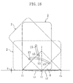
- FIG. 17 shows a locus of a point C2 which lies on the line formed by connecting the vertex C1 of the bottom corner 2b and the second guide pin 15 under the movement restriction by the cam 10.
- the vertex C1 of the bottom corner 2b forms a locus L1 which overlaps the hinge 6.
- the bottom corner 2b is actually rounded, the lowermost part of the rounded corner draws a linear locus L2 while keeping a certain clearance S from the hinge 6.
- the liquid crystal display part 2 does not go below the locus L2
- the liquid crystal display part 2 is rotated without contacting the hinge 6 even if the bottom end of the liquid crystal display part 2 is not rounded to form an arc corresponding to the circumference of a circle having the support shaft of the liquid crystal display part 2 as the center.
- the electric cable 21 moves within the cam opening 3d of the first housing 1 while being covered with the cable housing 22, the electric cable 21 is not tangled with other components.
- the horizontal center of the liquid crystal display part 2 is positioned substantially at the horizontal center of the first housing 3.
- a landscape image is displayed full on the screen of the landscape liquid crystal display 2a, and then the user does input with the operation keys of the operation part 4 to take part in a quiz show, do shopping or complete payment to a bank account through the display.
- the liquid crystal display part 2 is rotated counterclockwise when viewed from the front against the biasing force of the torsion coil spring 20.
- the torsion coil spring 20 goes beyond the position where the angle of deflection is the maximum, the liquid crystal display part 2 returns to the portrait orientation with the help of the biasing force.
- the cellular phone 1 is closed to be in the standby state.
- the liquid crystal display part 2 is supported on the first housing 3 by the cam 10 such that the orientation is changeable between portrait and landscape.
- the cam 10 supports and guides the liquid crystal display part 2 such that the bottom corner 2b of the liquid crystal display part 2 moves along the hinge 6 when the orientation of the liquid crystal display part 2 is changed. Therefore, the liquid crystal display part 2 is enlarged without increasing the size of the cellular phone 1 itself. Further, the orientation of the liquid crystal display part 2 is easily changed between portrait and landscape and the user can use the operation part 4 in the portrait orientation as usual even when the liquid crystal display 2a is landscape-oriented.
- the cam 10 serves as the support mechanism. Therefore, the orientation of the liquid crystal display part 2 is surely changed while the bottom corner 2b of the liquid crystal display part 2 moves along the hinge 6 without receiving any interference.
- the cam 10 makes it possible to switch the orientation of the liquid crystal display part 2 without receiving any interference while the horizontal center of the liquid crystal display part 2, regardless of whether portrait- or landscape-oriented, is positioned substantially at the horizontal center of the first housing 3. Therefore, the display screen is enlarged as much as possible and the liquid crystal display part 2 is positioned substantially at the horizontal center of the cellular phone 1 regardless of the orientation thereof.
- the folding cellular phone 1 is provided with good looks, a visible liquid crystal display and ease of operation.
- the liquid crystal display part 2 has a linear side which comes to the bottom in the portrait orientation.
- the cam 10 supports the liquid crystal display part 2 such that the bottom corner 2b moves along the hinge 6 to draw a linear locus L2 when the orientation of the liquid crystal display part 2 is changed between portrait and landscape. Therefore, the display screen is enlarged nearly to the bottom end of the portrait liquid crystal display part 2.
- the folding cellular phone 1 is provided with a larger display and greater ease of operation.
- the orientation of the liquid crystal display part 2 is changed to portrait or landscape by rotating the liquid crystal display part 2 such that the bottom corner 2b moves along the hinge 6 while the first guide pin 13 is engaged with and slides on the horizontal guide groove 12 and the second guide pin 15 is engaged with and slides with the vertical guide groove 14.
- the orientation of the liquid crystal display part 2 is easily and surely changed to portrait or landscape with a simple structure without receiving any interference.
- the cam 10 is provided with the torsion coil spring 20 for biasing the liquid crystal display part 2 to change the orientation to portrait or landscape. Therefore, the user can change the orientation of the liquid crystal display part 2 with a single motion by a single hand.
- the torsion coil spring 20 which is simple and hard to break is connected to the first guide pin 13 at one end and to the pin 19 of the first housing 3 at the other end. Therefore, the cam 10 moves smoothly and is achieved at low cost.
- the cable housing 22 is formed in the liquid crystal display part 2 to bulge toward the first housing 3 and the electric cable 21 is arranged therein to be slightly inclined with respect to the rear surface of the liquid crystal display part 2. Therefore, the first housing 3 and the liquid crystal display part 2 are reduced in thickness and the folding cellular phone 1 becomes thin and compact.
- the cam 10 is a unit assembly including the first and second guide pins 13 and 15 arranged precisely in the guide grooves 12 and 14. Therefore, the cam 10 is easily installed. Further, if the cam 10 is made of metal, the cam 10 moves more smoothly and increases rigidity.
- the folding cellular phone of the present invention may also have the following structures.
- the horizontal guide groove 12 and the vertical guide groove 14 are not limited to have the shapes as described above.
- the guide grooves may be shaped as shown in FIG. 18. Also in this case, the lowermost part of the rounded bottom corner 2b is guided to move along the linear locus L2 while keeping a certain clearance S from the hinge 6.
- the liquid crystal display part 2 is supported and guided by the cam 10 such that the bottom corner 2b of the liquid crystal display part 2 moves to along the hinge 6 to draw the linear locus L2.
- the bottom corner 2b may draw a curved locus L2.
- the shape of the horizontal guide groove 12 changed to control the locus L2.
- a camera may be arranged in a bulge between the bottom side of the first housing 3 and the hinge 6.
- the bottom corner 2b of the liquid crystal display part 2 is prevented from receiving the interference of the bulge.
- the number of the horizontal guide groove 12 may be increased to two.
- a second horizontal guide groove in the form of a tighter upward convex arc is formed above the horizontal guide groove 14 to be engaged with another first guide pin formed on the linking member 18.
- the second horizontal guide groove may be formed on the locus drawn by the point C2 shown in FIG. 17.
- the horizontal guide groove 12, vertical guide groove 14, first guide pin 13 and second guide pin 15 are assembled into a unit, but these components may not be assembled into a unit.
- the horizontal and vertical guide grooves 12 and 14 are integrally formed in the first housing body 3b of the first housing 3 and the first and second guide pins 15 may be integrated with the rear surface of the liquid crystal display part 2.
- the electric cable 21 is arranged to pass through the cable housing 22 to be slightly inclined with respect to the rear surface of the liquid crystal display part 2.
- the electric cable 21 may pass through a through hole 15b (shown in FIG. 10) formed in the second guide pin 15. By so doing, the electric cable 21 moves less because the second guide pin 15 moves the least when the orientation is changed. Further, the electric cable 21 is arranged easily.
- the torsion coil spring 20 is arranged to bias the liquid crystal display part 2 to change the orientation to portrait and landscape.
- the torsion coil spring 20 may bias the liquid crystal display part 2 to change the orientation to portrait or landscape only.
- the cam 10 rotates the liquid crystal display part 2 clockwise as viewed from the front to change the orientation from portrait to landscape.
- the liquid crystal display part 2 may be rotated counterclockwise to change the orientation.
- the horizontal center of the portrait- or landscape-oriented liquid crystal display device 2 is positioned substantially at the horizontal center of the first housing 3.
- the horizontal center of the liquid crystal display part 2 may be shifted to the right or left.
- the support mechanism is achieved by the cam 10, but this is not limitative.
- the support mechanism may be any structure as long as it supports and guides the liquid crystal display part 2 such that the bottom corner 2b of the liquid crystal display part 2 moves along the hinge 6 when the orientation of the liquid crystal display part 2 is changed between portrait and landscape.
- the liquid crystal display part 2 is provided with the liquid crystal display 2a.
- the liquid crystal display 2a may be replaced with an organic electroluminescence display.
Applications Claiming Priority (1)
| Application Number | Priority Date | Filing Date | Title |
|---|---|---|---|
| JP2005024070A JP4384059B2 (ja) | 2005-01-31 | 2005-01-31 | 折畳み式携帯電話 |
Publications (2)
| Publication Number | Publication Date |
|---|---|
| EP1686768A2 true EP1686768A2 (de) | 2006-08-02 |
| EP1686768A3 EP1686768A3 (de) | 2009-08-12 |
Family
ID=36215715
Family Applications (1)
| Application Number | Title | Priority Date | Filing Date |
|---|---|---|---|
| EP06001253A Withdrawn EP1686768A3 (de) | 2005-01-31 | 2006-01-20 | Klappbares Telefon mit rotierender Anzeige |
Country Status (6)
| Country | Link |
|---|---|
| US (1) | US7546150B2 (de) |
| EP (1) | EP1686768A3 (de) |
| JP (1) | JP4384059B2 (de) |
| KR (1) | KR100709652B1 (de) |
| CN (2) | CN101459702B (de) |
| HK (1) | HK1092303A1 (de) |
Cited By (8)
| Publication number | Priority date | Publication date | Assignee | Title |
|---|---|---|---|---|
| EP1898606A2 (de) | 2006-09-07 | 2008-03-12 | Samsung Electronics Co., Ltd. | Scharniervorrichtung mit mehreren Achsen für ein tragbares Endgerät und Anschlusselement mit mehreren Achsen |
| WO2008028456A1 (de) * | 2006-09-05 | 2008-03-13 | Lumberg Connect Gmbh | Mechanismus zum öffnen bzw. schliessen eines gerätes |
| EP1914962A2 (de) | 2006-10-19 | 2008-04-23 | Sharp Kabushiki Kaisha | Mobiles Endgerät mit Schiebemechanismus |
| EP1926290A1 (de) | 2006-11-23 | 2008-05-28 | Samsung Electronics Co., Ltd. | Scharniergelenkvorrichtung eines tragbaren Endgeräts und Doppelgelenkvorrichtung damit |
| EP2197180A1 (de) * | 2007-11-12 | 2010-06-16 | Fujikura, Ltd. | Elektronische einheit und elektronischer kabelbaum |
| EP2202948A1 (de) * | 2007-10-11 | 2010-06-30 | Nec Corporation | Tragbares informationsverarbeitungsendgerät |
| CN101287023B (zh) * | 2007-04-10 | 2011-12-28 | 安费诺凤凰株式会社 | 用于便携式电话的滑动型开启和关闭装置 |
| FR3116171A1 (fr) | 2020-11-09 | 2022-05-13 | Alexandre Mazer | dispositif de téléphonie portable |
Families Citing this family (86)
| Publication number | Priority date | Publication date | Assignee | Title |
|---|---|---|---|---|
| CN100391103C (zh) * | 1999-10-27 | 2008-05-28 | 菲罗兹·加萨比安 | 集成袖珍键盘系统 |
| AU2005253600B2 (en) * | 2004-06-04 | 2011-01-27 | Benjamin Firooz Ghassabian | Systems to enhance data entry in mobile and fixed environment |
| JP2006157464A (ja) * | 2004-11-29 | 2006-06-15 | Kyocera Corp | 音響装置 |
| EA200800069A1 (ru) | 2005-06-16 | 2008-06-30 | Фируз Гассабиан | Система ввода данных |
| KR100724956B1 (ko) * | 2005-12-13 | 2007-06-04 | 삼성전자주식회사 | 이동 통신 단말의 배경화면 표시 방법 |
| JP4554510B2 (ja) * | 2005-12-28 | 2010-09-29 | スガツネ工業株式会社 | ヒンジ装置及び携帯機器 |
| JP4227994B2 (ja) * | 2006-01-13 | 2009-02-18 | シャープ株式会社 | 折畳み式携帯機器 |
| KR100713479B1 (ko) * | 2006-06-08 | 2007-05-02 | 삼성전자주식회사 | 휴대 단말기 및 그의 슬라이딩/스윙 거치 장치 |
| US20080141125A1 (en) * | 2006-06-23 | 2008-06-12 | Firooz Ghassabian | Combined data entry systems |
| JP4413210B2 (ja) * | 2006-07-27 | 2010-02-10 | シャープ株式会社 | 折畳み式携帯通信機器 |
| US8352000B2 (en) * | 2006-08-22 | 2013-01-08 | Samsung Electronics Co., Ltd. | Mobile phone having dual connection member and hinge device thereof |
| KR100810277B1 (ko) * | 2006-08-22 | 2008-03-06 | 삼성전자주식회사 | 듀얼 연결부재를 구비한 휴대 단말기 및 그의 힌지 장치 |
| KR100764228B1 (ko) * | 2006-09-07 | 2007-10-08 | 암페놀피닉스 주식회사 | 휴대전화기용 스윙힌지 및 그 휴대전화기의 작동방법 |
| JP4568259B2 (ja) * | 2006-09-19 | 2010-10-27 | スガツネ工業株式会社 | ヒンジ装置 |
| US8380257B2 (en) * | 2006-09-26 | 2013-02-19 | Samsung Electronics Co., Ltd. | Swing-type mobile communication terminal and swing device thereof |
| KR100800712B1 (ko) * | 2006-10-02 | 2008-02-01 | 삼성전자주식회사 | 스윙 타입 이동 통신 단말기의 반자동 스윙 장치 |
| JP4638403B2 (ja) * | 2006-11-09 | 2011-02-23 | 株式会社山本精密 | スライド・回転取付ユニット及び電子機器 |
| JP4604015B2 (ja) * | 2006-11-20 | 2010-12-22 | シャープ株式会社 | 携帯機器 |
| KR100790076B1 (ko) * | 2006-11-23 | 2008-01-02 | 삼성전자주식회사 | 휴대 단말기의 회전 힌지 장치 및 이를 구비한 듀얼 힌지장치, 스윙형 휴대 단말기 |
| KR101409658B1 (ko) * | 2007-11-06 | 2014-06-19 | 삼성전자주식회사 | 휴대 단말기의 회전 힌지 장치 |
| JP2008153901A (ja) * | 2006-12-15 | 2008-07-03 | Fujitsu Ltd | 電子機器 |
| JP4709128B2 (ja) * | 2006-12-15 | 2011-06-22 | 富士通株式会社 | 電子機器 |
| KR101279512B1 (ko) * | 2006-12-26 | 2013-06-28 | 엘지전자 주식회사 | 싸이클로이드 구조의 회전형 힌지 조립체를 가지는 휴대단말기 |
| KR100860671B1 (ko) * | 2007-01-22 | 2008-09-26 | 삼성전자주식회사 | 휴대 단말기의 회전 힌지 장치 및 이를 구비한 듀얼 힌지장치, 스윙형 휴대 단말기 및 슬라이딩/회전형 휴대 단말기 |
| KR100800713B1 (ko) * | 2007-01-29 | 2008-02-01 | 삼성전자주식회사 | 휴대용 단말기 |
| JP4733062B2 (ja) * | 2007-02-06 | 2011-07-27 | シャープ株式会社 | 折畳み式携帯通信端末 |
| JP4973221B2 (ja) * | 2007-02-14 | 2012-07-11 | 富士通株式会社 | 携帯端末装置 |
| JP4875518B2 (ja) * | 2007-03-06 | 2012-02-15 | シャープ株式会社 | 折畳み式携帯端末 |
| JP4820319B2 (ja) * | 2007-03-22 | 2011-11-24 | シャープ株式会社 | 折畳み式携帯端末 |
| JP4288287B2 (ja) | 2007-03-22 | 2009-07-01 | シャープ株式会社 | 折畳み式携帯端末 |
| JP4416804B2 (ja) | 2007-03-26 | 2010-02-17 | シャープ株式会社 | 携帯端末 |
| KR100802012B1 (ko) * | 2007-05-09 | 2008-02-12 | 주식회사 피앤텔 | 슬라이딩 선회장치 |
| JP5044281B2 (ja) * | 2007-05-15 | 2012-10-10 | 株式会社山本精密 | スライド回転取付ユニット及び携帯電話機 |
| CA2687137A1 (en) * | 2007-05-18 | 2008-11-27 | Magna Seating Inc. | Deployable center armrest |
| KR100842629B1 (ko) * | 2007-05-23 | 2008-06-30 | 삼성전자주식회사 | 휴대용 전자 장치의 회전 힌지 장치 및 이를 구비한 듀얼힌지 장치 |
| JP5263154B2 (ja) | 2007-05-30 | 2013-08-14 | 日本電気株式会社 | 携帯型電子機器 |
| TW200909700A (en) * | 2007-08-17 | 2009-03-01 | Asustek Comp Inc | Foldable electronic device |
| KR20090021481A (ko) * | 2007-08-27 | 2009-03-04 | 삼성전자주식회사 | 힌지를 통과하는 케이블을 구비하는 휴대 단말기 |
| IL188523A0 (en) * | 2008-01-01 | 2008-11-03 | Keyless Systems Ltd | Data entry system |
| KR100875857B1 (ko) * | 2007-09-12 | 2008-12-26 | 암페놀피닉스 주식회사 | 휴대전화기용 스윙힌지 |
| KR100875856B1 (ko) * | 2007-10-04 | 2008-12-26 | 암페놀피닉스 주식회사 | 휴대전화기용 스윙힌지 |
| US20100216516A1 (en) * | 2007-10-05 | 2010-08-26 | Mikio Fujiwara | Terminal having display section |
| JP4899190B2 (ja) * | 2007-10-31 | 2012-03-21 | Necカシオモバイルコミュニケーションズ株式会社 | 携帯電子機器 |
| JP4917517B2 (ja) * | 2007-11-16 | 2012-04-18 | 株式会社山本精密 | スライド回転取付ユニット及び携帯電話機 |
| JP5221108B2 (ja) * | 2007-11-16 | 2013-06-26 | 株式会社山本精密 | スライド回転取付ユニット及び携帯電話機 |
| US7779509B2 (en) * | 2007-11-21 | 2010-08-24 | Shin Zu Shing Co., Ltd. | Sliding hinge |
| US20090145337A1 (en) * | 2007-12-05 | 2009-06-11 | Shin Zu Shing Co., Ltd. | Slidable hinge |
| KR101413012B1 (ko) * | 2007-12-05 | 2014-07-01 | 삼성전자주식회사 | 회전 힌지 모듈과 이를 구비하는 휴대 단말기 |
| CN101470530B (zh) * | 2007-12-26 | 2010-09-29 | 深圳富泰宏精密工业有限公司 | 键盘装置及具有该键盘装置的便携式电子装置 |
| JP5061366B2 (ja) * | 2008-01-04 | 2012-10-31 | Necカシオモバイルコミュニケーションズ株式会社 | ヒンジ構造、及び折り畳み式電子機器 |
| JP4899191B2 (ja) * | 2008-01-21 | 2012-03-21 | Necカシオモバイルコミュニケーションズ株式会社 | 携帯電子機器 |
| US7752712B2 (en) * | 2008-01-21 | 2010-07-13 | Shin Zu Shing Co., Ltd. | Hinge |
| JP4924463B2 (ja) * | 2008-02-14 | 2012-04-25 | 富士通株式会社 | 自動スイング機構及び携帯機器 |
| JP4899193B2 (ja) * | 2008-02-20 | 2012-03-21 | Necカシオモバイルコミュニケーションズ株式会社 | 電子機器 |
| JP5082920B2 (ja) * | 2008-02-25 | 2012-11-28 | 富士通株式会社 | 防水型ヒンジモジュールおよび電子機器 |
| JP5073563B2 (ja) * | 2008-04-10 | 2012-11-14 | 株式会社山本精密 | 筐体相互の連結ユニット及び携帯端末 |
| JP4659059B2 (ja) * | 2008-04-11 | 2011-03-30 | 株式会社ストロベリーコーポレーション | 相対移動付勢装置並びに相対移動付勢装置を用いた電子機器 |
| CN102027734A (zh) * | 2008-05-16 | 2011-04-20 | 夏普株式会社 | 带脉搏计的便携终端 |
| JP4505525B2 (ja) * | 2008-07-28 | 2010-07-21 | シャープ株式会社 | 携帯端末 |
| JP4436876B2 (ja) * | 2008-08-28 | 2010-03-24 | シャープ株式会社 | 携帯端末 |
| EP2309705A4 (de) * | 2008-07-28 | 2014-06-04 | Sharp Kk | Mobiles endgerät |
| EP2339819A4 (de) * | 2008-10-20 | 2013-01-02 | Nec Corp | Vorrichtung und verfahren zur statuserkennung in einer mobilvorrichtung |
| JP5121742B2 (ja) * | 2009-01-15 | 2013-01-16 | 三菱電機株式会社 | 表示装置 |
| JP5262769B2 (ja) * | 2009-01-30 | 2013-08-14 | 富士通株式会社 | 情報端末装置及びヒンジユニット |
| WO2010098774A1 (en) * | 2009-02-28 | 2010-09-02 | Hewlett-Packard Development Company, L.P. | Latch system |
| JP5110024B2 (ja) * | 2009-03-31 | 2012-12-26 | 富士通株式会社 | 情報処理端末 |
| US20110061484A1 (en) * | 2009-09-16 | 2011-03-17 | Kabushiki Kaisha Strawberry Corporation | Device for urging relative movement and electronic apparatus employing device for urging relative movement |
| JP4783847B2 (ja) | 2009-11-09 | 2011-09-28 | シャープ株式会社 | 携帯端末 |
| KR101601981B1 (ko) * | 2010-02-05 | 2016-03-17 | 삼성전자주식회사 | 휴대용 통신 장치 및 그의 거치 장치 |
| US8723814B2 (en) | 2010-05-10 | 2014-05-13 | Blackberry Limited | Handheld electronic communication device |
| EP2387208B1 (de) | 2010-05-10 | 2014-03-05 | BlackBerry Limited | Tragbare elektronische Kommunikationsvorrichtung |
| CN102255987A (zh) * | 2010-05-20 | 2011-11-23 | 深圳富泰宏精密工业有限公司 | 旋转机构及具有该旋转机构的电子装置 |
| CN102255986B (zh) * | 2010-05-20 | 2014-04-30 | 深圳富泰宏精密工业有限公司 | 旋转机构及具有该旋转机构的电子装置 |
| KR100993221B1 (ko) * | 2010-05-28 | 2010-11-10 | 한종근 | 힌지장치를 이용한 휴대용 단말기 케이스 |
| JP5194062B2 (ja) * | 2010-06-16 | 2013-05-08 | シャープ株式会社 | 携帯端末 |
| CN201774779U (zh) * | 2010-07-21 | 2011-03-23 | 深圳富泰宏精密工业有限公司 | 防护结构及具有该防护结构的便携式电子装置 |
| CN102469726A (zh) * | 2010-11-16 | 2012-05-23 | 深圳富泰宏精密工业有限公司 | 滑盖机构及应用其的便携式电子装置 |
| US8693188B2 (en) | 2011-05-24 | 2014-04-08 | Blackberry Limited | Pivotable display guide mechanism for an electronic mobile device |
| TW201339445A (zh) * | 2012-03-27 | 2013-10-01 | Wistron Corp | 轉軸機構及其掀蓋式裝置 |
| US8971031B2 (en) | 2012-08-07 | 2015-03-03 | Creator Technology B.V. | Display system with a flexible display |
| JP6452986B2 (ja) * | 2014-08-12 | 2019-01-16 | Re・Leaf株式会社 | 支持スタンド |
| US10890288B2 (en) * | 2018-04-13 | 2021-01-12 | Microsoft Technology Licensing, Llc | Systems and methods of providing a multipositional display |
| CN111449528A (zh) * | 2019-01-18 | 2020-07-28 | 佛山市顺德区美的电热电器制造有限公司 | 烹饪器具的上盖组件和烹饪器具 |
| JP7358963B2 (ja) * | 2019-02-20 | 2023-10-11 | 株式会社リコー | ディスプレイ用スタンド及びディスプレイスタンドシステム |
| TWI727787B (zh) * | 2019-05-23 | 2021-05-11 | 仁寶電腦工業股份有限公司 | 具滑轉機制的電子裝置 |
| CN112198928B (zh) * | 2020-09-30 | 2023-05-02 | 联想(北京)有限公司 | 一种电子设备 |
Citations (1)
| Publication number | Priority date | Publication date | Assignee | Title |
|---|---|---|---|---|
| EP0703401A1 (de) | 1994-08-22 | 1996-03-27 | Casio Computer Company Limited | Einrichtung zum Schwenken einer Platte |
Family Cites Families (37)
| Publication number | Priority date | Publication date | Assignee | Title |
|---|---|---|---|---|
| US20020073588A1 (en) * | 1990-06-11 | 2002-06-20 | Reynolds Randy B. | Point-of-purchase advertising by a cantilevered display mechanism and related methods |
| US6266045B1 (en) * | 1994-06-30 | 2001-07-24 | Telxon Corporation | Interactive display user interface computer and method |
| JPH08185242A (ja) | 1994-12-27 | 1996-07-16 | Casio Comput Co Ltd | 情報処理機器 |
| JP3360455B2 (ja) | 1994-12-27 | 2002-12-24 | カシオ計算機株式会社 | 情報処理機器 |
| US5708561A (en) * | 1996-08-13 | 1998-01-13 | Vivek R. Huilgol | Portable computer having display slidably and rotatably mounted for movement between landscape and portrait orientation and to open and close speaker ports |
| JP2000020166A (ja) | 1998-06-30 | 2000-01-21 | Nikko Ind Corp | 表示部の回転機構及びこれを備えた電子機器 |
| DE69824289T2 (de) * | 1998-09-21 | 2005-06-16 | Hewlett-Packard Development Co., L.P., Houston | Drehbare Anzeigevorrichtung |
| JP2001142408A (ja) | 1999-11-17 | 2001-05-25 | Hitachi Ltd | 画像表示装置 |
| JP2001156893A (ja) | 1999-11-29 | 2001-06-08 | Nec Saitama Ltd | 通信機器の表示システム及び方法 |
| JP2002341998A (ja) | 2001-05-16 | 2002-11-29 | Casio Comput Co Ltd | 情報処理装置及び文字入力装置 |
| CN1177453C (zh) * | 2001-07-19 | 2004-11-24 | 朱占新 | 可旋显示屏移动电话 |
| JP2003174495A (ja) * | 2001-09-28 | 2003-06-20 | Nec Corp | 折り畳み式携帯情報端末 |
| JP3770146B2 (ja) | 2001-10-29 | 2006-04-26 | 三菱電機株式会社 | 携帯情報端末 |
| KR100486611B1 (ko) * | 2001-12-18 | 2005-05-03 | 주식회사 팬택앤큐리텔 | 회전가능한 액정표시장치를 가지는 이동통신 단말기 |
| JP2003244293A (ja) * | 2002-02-14 | 2003-08-29 | Nec Corp | 折り畳み式携帯情報端末 |
| JP4061473B2 (ja) * | 2002-04-26 | 2008-03-19 | 日本電気株式会社 | 折り畳み型携帯電話機 |
| JP2004054409A (ja) | 2002-07-17 | 2004-02-19 | Natural Foods & Life:Kk | 携帯情報端末機 |
| JP3595547B2 (ja) | 2002-08-22 | 2004-12-02 | シャープ株式会社 | 薄型表示装置 |
| JP3839383B2 (ja) | 2002-09-27 | 2006-11-01 | 富士写真フイルム株式会社 | 携帯端末装置 |
| KR100484732B1 (ko) | 2002-11-19 | 2005-04-22 | 삼성전자주식회사 | 슬라이딩 타입 휴대용 무선 단말기 |
| JP2004253526A (ja) | 2003-02-19 | 2004-09-09 | Strawberry Corporation | スライド装置並びにスライド装置を用いた電子機器 |
| FI118668B (fi) * | 2003-04-01 | 2008-01-31 | Samsung Electro Mech | Matkapuhelin ja sen automaattinen pyöritysmenetelmä |
| JP4192024B2 (ja) * | 2003-04-17 | 2008-12-03 | 加藤電機株式会社 | 携帯端末用取付装置 |
| KR100678041B1 (ko) | 2003-11-24 | 2007-02-01 | 삼성전자주식회사 | 슬라이딩/회전성 힌지 수단을 구비한 휴대용 디지털 통신장치 |
| JP4031776B2 (ja) * | 2004-04-30 | 2008-01-09 | 松下電器産業株式会社 | 放送用受信機付き携帯電話 |
| WO2005117400A1 (ja) * | 2004-05-31 | 2005-12-08 | Sharp Kabushiki Kaisha | 携帯通信端末 |
| JP4286735B2 (ja) * | 2004-07-08 | 2009-07-01 | シャープ株式会社 | 携帯機器 |
| JP2004302491A (ja) | 2004-07-15 | 2004-10-28 | Sharp Corp | 液晶表示装置 |
| EP1791328A1 (de) * | 2004-09-14 | 2007-05-30 | Mitsubishi Denki Kabushiki Kaisha | Mobile vorrichtung |
| EP1798940A4 (de) * | 2004-10-01 | 2010-03-17 | Sharp Kk | Mobil-informationsendgerät |
| KR100630068B1 (ko) * | 2005-01-25 | 2006-09-27 | 삼성전자주식회사 | 디스플레이 회전형 휴대 단말기의 힌지 장치 |
| JP4190509B2 (ja) * | 2005-03-02 | 2008-12-03 | シャープ株式会社 | 折畳み式携帯電話 |
| US20060246964A1 (en) * | 2005-04-29 | 2006-11-02 | Castaneda Julio C | Electronic device comprising a single hinge twist mechanism and a method to use same |
| JP4127842B2 (ja) * | 2006-06-05 | 2008-07-30 | 株式会社東芝 | 情報処理装置 |
| US8352000B2 (en) * | 2006-08-22 | 2013-01-08 | Samsung Electronics Co., Ltd. | Mobile phone having dual connection member and hinge device thereof |
| CN101140008B (zh) * | 2006-09-05 | 2012-11-21 | 鸿富锦精密工业(深圳)有限公司 | 铰链结构 |
| US8364214B2 (en) * | 2006-12-14 | 2013-01-29 | Nokia Corporation | Electrically released magnet locking mechanism |
-
2005
- 2005-01-31 JP JP2005024070A patent/JP4384059B2/ja not_active Expired - Fee Related
- 2005-12-07 US US11/295,452 patent/US7546150B2/en not_active Expired - Fee Related
-
2006
- 2006-01-20 EP EP06001253A patent/EP1686768A3/de not_active Withdrawn
- 2006-01-27 KR KR1020060008677A patent/KR100709652B1/ko not_active IP Right Cessation
- 2006-01-28 CN CN2008101795782A patent/CN101459702B/zh not_active Expired - Fee Related
- 2006-01-28 CN CNB200610004779XA patent/CN100525125C/zh not_active Expired - Fee Related
- 2006-11-17 HK HK06112703.7A patent/HK1092303A1/xx not_active IP Right Cessation
Patent Citations (1)
| Publication number | Priority date | Publication date | Assignee | Title |
|---|---|---|---|---|
| EP0703401A1 (de) | 1994-08-22 | 1996-03-27 | Casio Computer Company Limited | Einrichtung zum Schwenken einer Platte |
Cited By (18)
| Publication number | Priority date | Publication date | Assignee | Title |
|---|---|---|---|---|
| WO2008028456A1 (de) * | 2006-09-05 | 2008-03-13 | Lumberg Connect Gmbh | Mechanismus zum öffnen bzw. schliessen eines gerätes |
| EP1898606A2 (de) | 2006-09-07 | 2008-03-12 | Samsung Electronics Co., Ltd. | Scharniervorrichtung mit mehreren Achsen für ein tragbares Endgerät und Anschlusselement mit mehreren Achsen |
| US8250712B2 (en) | 2006-09-07 | 2012-08-28 | Samsung Electronics Co., Ltd | Hinge device having a plurality of axes for a portable terminal and a connection member having the plurality of axes |
| EP1898606A3 (de) * | 2006-09-07 | 2009-03-18 | Samsung Electronics Co., Ltd. | Scharniervorrichtung mit mehreren Achsen für ein tragbares Endgerät und Anschlusselement mit mehreren Achsen |
| EP1914962A2 (de) | 2006-10-19 | 2008-04-23 | Sharp Kabushiki Kaisha | Mobiles Endgerät mit Schiebemechanismus |
| EP1914962A3 (de) * | 2006-10-19 | 2010-01-27 | Sharp Kabushiki Kaisha | Mobiles Endgerät mit Schiebemechanismus |
| US8014842B2 (en) | 2006-10-19 | 2011-09-06 | Sharp Kabushiki Kaisha | Sliding type mobile terminal |
| US7991441B2 (en) | 2006-11-23 | 2011-08-02 | Samsung Electronics Co., Ltd | Swing hinge device of a portable terminal and dual hinge device having the same |
| EP1926290A1 (de) | 2006-11-23 | 2008-05-28 | Samsung Electronics Co., Ltd. | Scharniergelenkvorrichtung eines tragbaren Endgeräts und Doppelgelenkvorrichtung damit |
| CN101287023B (zh) * | 2007-04-10 | 2011-12-28 | 安费诺凤凰株式会社 | 用于便携式电话的滑动型开启和关闭装置 |
| EP2202948A1 (de) * | 2007-10-11 | 2010-06-30 | Nec Corporation | Tragbares informationsverarbeitungsendgerät |
| EP2202948A4 (de) * | 2007-10-11 | 2012-01-25 | Nec Corp | Tragbares informationsverarbeitungsendgerät |
| US8564936B2 (en) | 2007-10-11 | 2013-10-22 | Nec Corporation | Portable information processing terminal |
| CN101822028B (zh) * | 2007-10-11 | 2014-06-25 | 日本电气株式会社 | 便携式信息处理终端 |
| EP2197180A1 (de) * | 2007-11-12 | 2010-06-16 | Fujikura, Ltd. | Elektronische einheit und elektronischer kabelbaum |
| EP2197180A4 (de) * | 2007-11-12 | 2012-02-15 | Fujikura Ltd | Elektronische einheit und elektronischer kabelbaum |
| US8416581B2 (en) | 2007-11-12 | 2013-04-09 | Fujikura Ltd. | Electronic apparatus and electronic apparatus wiring harness having a flat U-shape |
| FR3116171A1 (fr) | 2020-11-09 | 2022-05-13 | Alexandre Mazer | dispositif de téléphonie portable |
Also Published As
| Publication number | Publication date |
|---|---|
| JP4384059B2 (ja) | 2009-12-16 |
| CN1816065A (zh) | 2006-08-09 |
| KR20060088044A (ko) | 2006-08-03 |
| EP1686768A3 (de) | 2009-08-12 |
| US7546150B2 (en) | 2009-06-09 |
| CN101459702A (zh) | 2009-06-17 |
| CN101459702B (zh) | 2013-03-13 |
| JP2006211576A (ja) | 2006-08-10 |
| CN100525125C (zh) | 2009-08-05 |
| US20060172764A1 (en) | 2006-08-03 |
| HK1092303A1 (en) | 2007-02-02 |
| KR100709652B1 (ko) | 2007-04-20 |
Similar Documents
| Publication | Publication Date | Title |
|---|---|---|
| US7546150B2 (en) | Folding cellular phone | |
| EP1699209B1 (de) | Faltbares Mobiltelefon welches Mittel zur Einschränkung des Öffnens und des Schliessens enthält | |
| JP4227994B2 (ja) | 折畳み式携帯機器 | |
| JP4484859B2 (ja) | スライド式携帯機器 | |
| EP1976239B1 (de) | Tragbare elektronische Vorrichtung | |
| JP4783847B2 (ja) | 携帯端末 | |
| EP1883206A1 (de) | Zusammenklappbare und tragbare Kommunikationsvorrichtung | |
| JP4733062B2 (ja) | 折畳み式携帯通信端末 | |
| JP4838874B2 (ja) | 回転支持機構 | |
| JP4384218B2 (ja) | 折畳み式携帯電話 | |
| JP4572183B2 (ja) | 折畳み式携帯機器 | |
| JP4317889B2 (ja) | 折畳み式携帯電話 | |
| JP4436876B2 (ja) | 携帯端末 | |
| JP4384219B2 (ja) | 折畳み式携帯電話 | |
| JP4228029B2 (ja) | 折畳み式携帯機器 | |
| JP4547354B2 (ja) | 折畳み式携帯通信機器 | |
| JP2007312330A (ja) | 折畳み式携帯通信機器 | |
| JP2008028846A (ja) | 折畳み式携帯通信機器 | |
| JP4820319B2 (ja) | 折畳み式携帯端末 | |
| JP2008034946A (ja) | 折畳み式携帯電話 | |
| JP2008035414A (ja) | 携帯端末装置 | |
| JP2007312329A (ja) | 折畳み式携帯通信機器 |
Legal Events
| Date | Code | Title | Description |
|---|---|---|---|
| PUAI | Public reference made under article 153(3) epc to a published international application that has entered the european phase |
Free format text: ORIGINAL CODE: 0009012 |
|
| AK | Designated contracting states |
Kind code of ref document: A2 Designated state(s): AT BE BG CH CY CZ DE DK EE ES FI FR GB GR HU IE IS IT LI LT LU LV MC NL PL PT RO SE SI SK TR |
|
| AX | Request for extension of the european patent |
Extension state: AL BA HR MK YU |
|
| PUAL | Search report despatched |
Free format text: ORIGINAL CODE: 0009013 |
|
| AK | Designated contracting states |
Kind code of ref document: A3 Designated state(s): AT BE BG CH CY CZ DE DK EE ES FI FR GB GR HU IE IS IT LI LT LU LV MC NL PL PT RO SE SI SK TR |
|
| AX | Request for extension of the european patent |
Extension state: AL BA HR MK YU |
|
| 17P | Request for examination filed |
Effective date: 20100212 |
|
| AKX | Designation fees paid |
Designated state(s): DE FR GB IT |
|
| 17Q | First examination report despatched |
Effective date: 20100419 |
|
| GRAP | Despatch of communication of intention to grant a patent |
Free format text: ORIGINAL CODE: EPIDOSNIGR1 |
|
| INTG | Intention to grant announced |
Effective date: 20130507 |
|
| STAA | Information on the status of an ep patent application or granted ep patent |
Free format text: STATUS: THE APPLICATION IS DEEMED TO BE WITHDRAWN |
|
| 18D | Application deemed to be withdrawn |
Effective date: 20130918 |