EP1657657A2 - Methode zur Simulation von Deformierungen von Gummimaterial - Google Patents
Methode zur Simulation von Deformierungen von Gummimaterial Download PDFInfo
- Publication number
- EP1657657A2 EP1657657A2 EP05022052A EP05022052A EP1657657A2 EP 1657657 A2 EP1657657 A2 EP 1657657A2 EP 05022052 A EP05022052 A EP 05022052A EP 05022052 A EP05022052 A EP 05022052A EP 1657657 A2 EP1657657 A2 EP 1657657A2
- Authority
- EP
- European Patent Office
- Prior art keywords
- model
- rubber
- filler
- deformation
- rubber material
- Prior art date
- Legal status (The legal status is an assumption and is not a legal conclusion. Google has not performed a legal analysis and makes no representation as to the accuracy of the status listed.)
- Granted
Links
Images


Classifications
-
- G—PHYSICS
- G01—MEASURING; TESTING
- G01N—INVESTIGATING OR ANALYSING MATERIALS BY DETERMINING THEIR CHEMICAL OR PHYSICAL PROPERTIES
- G01N33/00—Investigating or analysing materials by specific methods not covered by groups G01N1/00 - G01N31/00
- G01N33/44—Resins; Plastics; Rubber; Leather
-
- G—PHYSICS
- G06—COMPUTING OR CALCULATING; COUNTING
- G06F—ELECTRIC DIGITAL DATA PROCESSING
- G06F30/00—Computer-aided design [CAD]
- G06F30/20—Design optimisation, verification or simulation
- G06F30/23—Design optimisation, verification or simulation using finite element methods [FEM] or finite difference methods [FDM]
-
- G—PHYSICS
- G01—MEASURING; TESTING
- G01B—MEASURING LENGTH, THICKNESS OR SIMILAR LINEAR DIMENSIONS; MEASURING ANGLES; MEASURING AREAS; MEASURING IRREGULARITIES OF SURFACES OR CONTOURS
- G01B21/00—Measuring arrangements or details thereof, where the measuring technique is not covered by the other groups of this subclass, unspecified or not relevant
- G01B21/32—Measuring arrangements or details thereof, where the measuring technique is not covered by the other groups of this subclass, unspecified or not relevant for measuring the deformation in a solid
Definitions
- the present invention relates to a method of simulating deformation of a rubber material which comprises: a filler part made of at least one filler particle; and a rubber part made of rubber and surrounding the filler part, with good accuracy.
- the rubber material is widely used in for example, tires and industrial goods such as sporting goods.
- a simulation of for example, deformation process of the rubber material is carried out using a computer.
- the conventional simulation methods of the rubber material are described in for example, the following articles.
- the article (1) describes a method for analyzing a rubber material using a molecular chain network model theory. According to the method described in this article, however, strain-rate dependence of general rubber material can not be replicated.
- the strain-rate dependence is a characteristic of a rubber material showing different viscoelasticity characteristics depending upon its strain rate. That is, when amplitude strains of different frequencies (e.g., 10 Hz and 1,000 Hz) are applied to the same rubber test pieces, energy losses of the respective frequencies have different values. In the article (1), such the strain-rate dependence is not taken into consideration. Thus, material characteristics of different frequencies can not be evaluated precisely from one rubber material model.
- a pneumatic tire is used as an example of a rubber product, and two performances, i.e., its fuel efficiency and grip performance (index of stick of the tire with respect to a road surface at the time of acceleration and/or deceleration) will be considered.
- fuel efficiency and grip performance index of stick of the tire with respect to a road surface at the time of acceleration and/or deceleration
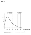
- Fig. 21 is a graph showing a relationship between the frequency of strain rate and the energy loss calculated using frequency-temperature conversion rule with respect to a tire rubber material, and the relationship is shown with solid line.
- the energy loss is also largely varied. According to the method of the article (1), however, even if the strain rate of the rubber model is changed, only the same energy loss is obtained as shown with chain double-dashed line. With this, data useful for developing rubber can not be obtained.
- the strain rate is a product of deformation frequency and strain.
- the article (2) describes that a rubber model is set from rubber material in which a filler is mixed, and the strain-rate dependence is taken into consideration.
- the handling of an interface between the filler and rubber is important problem.
- relatively high energy loss was generated due to slip or friction between the rubber and filler. Therefore, in order to carry out a precise simulation of rubber material, it is important to model the filler and the rubber separately.
- the filler and the rubber are modeled collectively not separately. With such a method, it is not impossible to obtain information such as a state of interface between rubber and filler and a distribution state of stress at the time of deformation.
- a method of simulating deformation of a rubber material having a filler part made of at least one filler particle and a rubber part surrounding the filler part comprises the steps of:
- the rubber material model used for the deformation calculation includes a filler model and a rubber model surrounding the filler model. Therefore, it is possible to know a distribution of physical value (e.g., stress and energy loss) around the filler. Therefore, more detail and more concrete analysis can be carried out. Such physical values data are visualized as a distribution chart, and this becomes useful information for developing rubber and/or filler materials.
- a distribution of physical value e.g., stress and energy loss
- strain-rate dependence is defined in the rubber model.
- a physical tester which applies periodic strain to a rubber and measures viscoelasticity thereof.
- the frequency of strain is as low as about 1,000 Hz. This is not sufficient to evaluate the grip performance of rubber products such as a tread rubber. If the strain-rate dependence is applied to the rubber model, viscoelasticity of high dimension which can not be obtained by the tester can be estimated.
- the rubber model includes an interface model and a matrix model.
- a filler-mixed rubber has a physical interface between the filler and rubber.
- the interface is a physical coupling.
- the filler is silica
- the interface is a chemical coupling by means of a coupling agent.
- Fig. 1 shows a computer apparatus 1 for carrying out a simulation method according to the present invention.
- the computer apparatus 1 includes a main unit 1a, a keyboard 1b, and a mouse 1c serving as input means, and a display 1d serving as output means.
- the main unit 1a is appropriately provided with a central processing unit (abbreviated as "a CPU"), a ROM, a working memory, a large-capacity storage device such as a magnetic disk, and drives 1a1 and 1a2 for a CD-ROM or a flexible disk.
- the large-capacity storage device stores therein processing procedures (i.e., programs) for executing a method, described later.
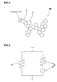
- Fig. 2 shows one example of a processing procedure of the simulation method according to the present invention.
- a rubber material model is first set (step S1).
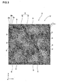
- Fig. 3 one example of the rubber material model 2 serving as a microscopic structure (It may be also called "unit cell”.) is visually shown.
- a microscopic region of the rubber material comprising a filler part made of at least one filler particle and a rubber part surrounding the filler part (no object on whether existent or not) to be analyzed is divided into a finite number of small elements 2a, 2b, 2c ....
- a parameter necessary for deformation calculation using a numerical analysis method is given to each element 2a, 2b, 2c ....
- the numerical analysis method includes for example, finite element method, finite volume method, calculus of finite differences, or boundary element method.
- the parameter includes for example, node coordinate value, element shape, and/or material property of each element 2a, 2b, 2c ....
- a triangular or a quadrilateral element serving as for example, a two-dimensional plane and a tetrahedral or a hexagonal element serving as a three-dimensional element is used for each element 2a, 2b, 2c ....
- the rubber material model 2 is numerical data utilizable in the computer apparatus 1.
- the two-dimensional rubber material model 2 is shown.
- the rubber material model 2 of this present embodiment is analyzed in a plane distorted state in a later-described deformation simulation. Therefore, the rubber material model 2 does not have a strain in the Z direction (direction perpendicular to the sheet of the drawing). Vertical and horizontal sizes of the rubber material model 2 of this embodiment are set to be 300x300 nanometers.
- the rubber material model 2 comprises at least one filler model 3 in which the filler part is modeled into a finite number of elements, and a rubber model 4 in which the rubber part is modeled into a finite number of elements disposed around the filler model.
- the rubber model 4 comprises at least one interface model 5 contacting around the filler model 3, and a matrix model 6 disposed outside the interface model.
- the interface model 5 is filling with a space between the filler model 3 and the matrix model 6.
- the filler model 3 is illustrated as a white part
- the matrix model 6 is illustrated as the darkest part
- the interface model 5 is illustrated as a little thin gray part.
- the filler model 3 in which a carbon black is modeled is shown. It is to be noted that the filler is not limited to carbon black and may be for example, silica and the like.
- the physical shape of the filler model 3 is set based on the shape of the carbon black particles filled in the actual rubber imaged with an electronic microscope.
- Fig. 4 shows a secondary particle CB of the carbon black.
- the secondary particle CB has, more specifically, a structure in which a plurality of spherical primary particles 7 each consisting of carbon atom having a diameter of approximately 10 nm is irregularly bonded three-dimensionally.
- the filler model 3 of this embodiment is set to the standard in the plane shape of above secondary particle CB of the carbon black.
- the carbon black has hardness (modulus of longitudinal elasticity) several hundred times harder than the matrix rubber.
- the filler model 3 is defined as an elastic body with a modulus of longitudinal elasticity as the material property, and the stress and the strain are proportional in the deformation calculation so as to not produce energy loss in the present embodiment.
- the number of filler model 3 in a cell unit is appropriately set based on the filler blending amount of the rubber material of the analyzing object.
- the interface model 5 is not necessarily limited to continuously surround the filler model 3, but preferably, surrounds the filler model 3 throughout the entire range.
- the interface model 5 has a small thickness.
- the thickness t of the interface model 5 is preferably set in a range of from 1 to 20 nm, and more preferably from 5 to 10 nm.
- the matrix model 6 comprises a finite number of triangular and/or quadrilateral elements, and constitutes a main part of the rubber material model 2 in a unit cell U.
- a strain-rate dependence in which stress generated in accordance with strain rate is varied is defined in the rubber model 4.
- Fig. 5 is a conception diagram used for explaining a deformation principle of the rubber model 4 with the strain-rate dependence.
- Each element of the rubber model 4 is expressed as a model in which a first deformation network "A" and a second deformation network B are coupled to each other in parallel.
- a stress S generated in the entire system is a sum of a stress generated in the first deformation network "A" and a stress generated in the second deformation network B. Since the networks A and B are coupled to each other in parallel, strains (extensions) generated in the networks A and B are the same.
- the first deformation network A is expressed as one which is equivalent to a coil spring.
- the stress generated in the first deformation network "A” assumes a value which is in proportion to the extension (strain) of the spring. Further, the extension of the spring generates only based on a load. Therefore, the stress which does not depend on the strain rate is generated in the first deformation network "A".
- the second deformation network B is expressed as a model that a coil spring e and a dashpot p are connected to each other in series.
- the dashpot p is a damping apparatus comprising a cylinder sealing fluid therein, and a piston with an orifice which moves in the cylinder.
- the fluid is pursuant to Newton's viscosity rule, and is oil for example. Resistance which is proportional to moving speed of the piston is generated in the dashpot e.
- the extension (strain) of the entire second deformation network B is equal to a sum of extensions of the spring e and dashpot p.
- stress generated in the second deformation network B is equal to a value corresponding to the extension (strain) of the spring e.
- the extension of the spring e is not simply determined in accordance with a load, and the extension is influenced by resistance of the dashpot p which depends on its strain rate. That is, the second deformation network B produces stress which depends on the strain rate.
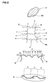
- the above mentioned molecular chain network model theory depends that the rubber material "a” has a network structure as a microscopic structure "da".
- the network structure of the rubber material includes a plurality of molecular chains c linked at a linking point b and arranged disorderly.
- the linking point b includes a chemical linking point between the molecules such as for example, a chemical cross-linking point.
- One molecular chain c comprises a plurality of segments d.
- One segment d is the smallest constitutional unit for repetition in the above mentioned theory. Further, one segment d is configured by joining a plurality of monomers f in which carbon atoms are linked by covalent bonding. Carbon atoms each freely rotates with respect to each other around a bond axis between the carbons. Thus, the segment d can be bent, as a whole, into various shapes.
- the macroscopic structure of the rubber material comprises a cubic network structure body h in which the microscopic eight chain rubber elasticity models g are collected.
- the molecular chain c extends from one linking point b1 placed at the center of the cube to each of the eight linking point b2 at each apex of the cube, as shown enlarged on the right side of Fig. 7.
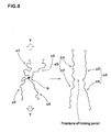
- the rubber material tolerates great strain reaching to several hundred % by stretching.
- the inventor et al. hypothesized that the great strain of the rubber material is produced when the debt portion such as the linking point b of the molecule chain c which became entangled intricately comes loose. That is, as shown in Fig. 8, when tensile stress shown as arrows Y is loaded to the molecular chains c1, c2, c3 and c4 linked at one linking point b, each molecular chain c1 to c4 stretch and the linking point b is subjected to great strain and tends to break (disappear). As shown on the right side of Fig. 8, the two molecular chains c1 and c2 act as one long molecular chain c5. The molecular chains c3 and c4 also act in the same way. In this method of this present embodiment, in order to obtain an exact result, the reduction of the linking point b of such a molecule chain c is taken into consideration in the equation (1) as follows.
- the network structure body h as shown in Fig. 7 is a body in which k number of eight chain rubber elasticity model are each bonded in the directions of the axis, the height, and the depth. It is to be noted that k is a sufficiently big number.
- the average segment number N in one molecular chain has to increase.
- the average segment number N is a variable parameter having different values according to the deformation, the reduction of the binding number m of the molecular chain by stretch can be expressed in the simulation.
- the loaded deformation is deformation in which distortion of rubber model 4 increases between minute time.
- the average segment number N is determined by various methods. For instance, the average segment number N can be increased based on the parameter related to strain during the loaded deformation.
- the parameter related to strain is not particularly limited and may be for example, strain, strain rate, or primary invariable quantity I 1 of strain.
- the average segment number N is defined by the following equation (9). This equation shows that the average segment number N is a function of the primary invariable quantity I 1 (more specifically, a parameter ⁇ c square root thereof) of strain in each element of the relevant rubber model 4.
- N ( ⁇ c ) A + B ⁇ ⁇ c + C ⁇ ⁇ c 2 + D ⁇ ⁇ c 3 + E ⁇ ⁇ c 4
- the average segment number N in each strain is derived so as to comply with the curve during when load is loaded.
- the parameters A to E of equation (9) are determined so as to comply with the determined average segment number N during loading.
- N 16 is used, and as for the value of N during unloaded deformation, the value at the time of the end of load is adopted.
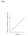
- a relationship between the average segment number N and the parameter ⁇ c during loaded deformation of each element of the rubber model 4 is shown.
- ⁇ c a parameter relating to strain
- the average segment number N is also gradually increased.
- the upper limit of parameter ⁇ c is 2.5.
- the parameter ⁇ c of each element of the rubber model 4 is calculated on a steady basis.
- the calculated ⁇ c is substituted to equation (9), and the average segment number N during the relevant strain state of the relevant element is calculated.
- the value of the average segment number N is held during unloaded deformation of the rubber model 4 in which load is reducing in a minute time.
- Second deformation network B
- the eight chains rubber elasticity model based on the molecular chain network model theory is also applied to the spring e of the second deformation network B. Therefore, stress generated in the second deformation network B is also calculated using the above mentioned equation (1). However, resistance depending upon strain rate is generated in the second deformation network B, and this exerts influence on extension ratio ⁇ c .
- each main stretch ⁇ i (Be) is calculated in accordance with the following procedure.
- a right shoulder subscript "Be” is a symbol used for distinguishing from the main stretch of the first deformation network A.
- corresponding shearing stress ⁇ (B) in the second deformation network B is calculated in the equation (10).
- ⁇ (B)' is a corresponding stress of the second deformation network B obtained by the calculation of the previous step.
- a strain rate of the dashpot p is calculated from the equation (11) by using value of corresponding shearing stress ⁇ (B) and ⁇ c (Bp) .
- the ⁇ c (Bp) in the equation (11) is an extension ratio of the dashpot p. This value is calculated based on the method of proviso of the equation (1) from the last calculated value ⁇ i (Bp) (calculated in the later-described equation (14)).
- a strain rate D (Bp) of the dashpot p is calculated from the following equation (12) from the strain rate.
- the extension of the dashpot p is calculated by the following equations (13) and (14) from the strain rate D (Bp) .
- the subscript t represents a time step of calculation, and ⁇ t represents increment thereof.
- Each stretch ⁇ i (Be) of the spring e of the second deformation network B is calculated from the following equation (15).
- ⁇ i represents extension ratio of the entire second deformation network B.
- ⁇ i ( B e ) ⁇ i / ⁇ i ( B p )
- the stress of the second deformation network B is calculated by substituting the ⁇ i (Be) into the equation (1).
- the entire stress of the rubber model 4 is calculated. This stress depends on the strain rate. This dependence is adjusted based on each material constants c1 and c2 in the equation (11).
- the strain rate dependence is defined by at least one of, preferably both of the interface model 5 and the matrix model 6.
- the strain-rate dependence is defined by both the interface model 5 and the matrix model 6.
- the interface model 5 has a viscoelastic property different from the matrix model 6.
- the viscoelastic property includes the characteristic expressed with the stress-strain curve at arbitrary deformation rates, as shown in Fig. 10.
- the interface model 5 of the present embodiment has a viscoelastic property softer than the matrix model 6 such that the inclination to the horizontal axis of the stress-strain curve of interface model 5 can be set up smaller than that of matrix model 6 as shown in Fig. 10.
- the area of a hysteresis loop of each stress-strain curve is also changeable.
- the viscoelasticity characteristic is set that the stress of interface model 5 becomes larger than matrix model 6.
- step S3 the deformation calculation (simulation) using the set rubber material model 2 is performed (step S3).
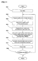
- Fig. 11 one example of a specific procedure of the deformation calculation is shown.
- necessary data is first input to the computer apparatus 1 (step S31).
- the input data includes for example, numerical data for configuring the rubber material model 2, and a variety of pre-set boundary conditions.
- step S32 A rigid matrix of each element is then formed (step S32) in the computer apparatus 1, and thereafter, the rigid matrix of the entire structure is assembled (step S33).
- step S34 A known node displacement and node force are adopted to the rigid matrix of the entire structure (step S34), and an analysis of the rigidity formula is carried out.
- the unknown node displacement is determined (step S35) and physical quantity such as strain, stress, and principal stress of each element are calculated and output (steps S36 and S37).
- step S38 a determination is made whether or not to finish the calculation, and if the calculation is not to be finished, steps after step S32 is repeated.
- the deformation calculation may be carried out using an engineering system analyzing application software (e.g., LS-DYNA and the like, developed and improved in Livermore Software Technology Corporation (US)) using the finite element method.
- application software e.g., LS-DYNA and the like, developed and improved in Livermore Software Technology Corporation (US)
- a rubber entire model M is set as shown in Fig. 12 for a homogenizing method.
- the entire model M comprises a great number of the unit cells U of the microscopic structure arranged periodically, and has a size which suits the computer simulation.
- the homogenizing method is used.
- the method comprises a first stage of simulating the whole by using the entire model M equivalent to the area for analysis, and a second stage of converting the result to the microscopic structure (unit cell) at arbitrary points in the area for analysis.
- the homogenizing method two independent variables of macroscopic scales X 1 and X 2 representing an entire model M and the microscopic scales y 1 and y 2 representing the unit cell U of the rubber material model 2 are used as shown in Fig. 12.
- the respective independent variable in different scales of the microscopic scales y 1 , y 2 and the macroscopic scales x 1 , x 2 are asymptotically developed.
- an average dynamic response of the entire model M of a certain size periodically including the unit cells U can be obtained.
- the asymptotically developing homogenizing method is a method already established in the numerical calculation method. The method is described in detail in for example, the following article.
- volume content of filler model 30%
- the average segment number N is calculated for each strain state, as mentioned above, and such value is substituted to equation (1) and the calculation is sequentially carried out.
- the three-dimensional eight chain rubber elasticity model of Aruuda et al. is used in the rubber material model 2 (the entire model M) without changing in the direction of thickness (direction of z axis in Fig. 3).
- the average segment number N of the matrix model 3 and the interface model 5 is set as the following:
- Fig. 14 shows another result of the present embodiment.
- the strain rate dependence is defined only in the interface model, and is not defined in the matrix model.
- Representative examples of the filler are carbon black and silica. The biggest difference therebetween is not the filler itself but is an interface between the filler surface and the rubber. It is considered that the rubber in the vicinity of the interface exerts sensitive influence on the material characteristics, and dependency on the strain rate is high. Therefore, it is effective to change the strain-rate dependence of the interface model and the matrix model to obtain an important idea as to how the filler and the polymer should be coupled to each other.
- strain rate dependence as shown in Fig. 14 is defined.
- an interface model 1 having carbon black has great strain rate dependence and energy loss is also set great.
- An interface model 2 having silica has small strain rate dependence and energy loss is also set small.
- the high speed deformation has the strain rate of 1,000 (/s) and the low speed deformation has the strain rate of 0.1 (/s).
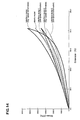
- Fig. 15 shows a result of the simulation.
- a vertical axis shows strain and a lateral axis shows true stress. From this result, it can be found that although only rate dependence of the interface model having small thickness is changed, a large difference is generated in the viscoelasticity characteristics of the rubber material.
- Fig. 16 is a graph in which a lateral axis shows elasticity modulus (inclination with respect to the lateral axis of the graph shown in Fig. 15), and a vertical axis shows energy loss (hysteresis loop). Concerning the grip performance of the previous tire, viscoelasticity characteristics extending in a left and upward direction of the graph is preferable.
- the simulation of this embodiment includes a step for forming and displaying a distribution chart from obtained data (step S5).
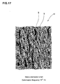
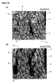
- Fig. 17 shows one example of the distribution chart of stress generated in each element of the unit cell U (this unit cell U is one shown in Fig. 12 not in Fig. 3) in the maximum strain state at the time of the high speed deformation. Further, variation of the outline shape of the unit cell U is also visualized.
- the step for forming the distribution diagram is carried out by replacing a stress value obtained for each element by information which can visually be identified such as color information (color saturation, hue, brightness and the like). In Fig. 17, greater strain has denser color saturation. From this result, it can be found that greater stress is concentrated on a portion where a distance between filler models 3 and 3 is smaller. It can also be found that a portion having higher stress is connected in a form of a line along a tensile direction through the filler model 3.
- Fig. 18 is a distribution chart of energy loss generated in each element of the unit cell U at the time of high speed deformation. To obtain the energy loss, load was removed at the same speed as that of each strain rate, and a stress strain curve of one cycle was obtained. The outline shape of the unit cell U shown in Fig. 17 was employed. In this distribution chart also, the energy loss obtained for each element was replaced by the color information (color saturation, hue, brightness and the like). Greater strain has denser color saturation. From this result also, it can be found that greater stress is generated on a portion where a distance between filler models 3 and 3 is smaller. The filler model 3 is colored but generates no energy loss. In addition, the data such as physical value used in the distribution chart is not limited to stress value or energy loss, and various values are employed in accordance with purpose of analysis.
- Figs. 19(A) and 19(B) are partial enlarged views of stress distributions of the unit cell U in the maximum strain state at the time of high speed deformation and low speed deformation, respectively, and show a state in which the stress distribution is varied depending upon difference of deformation frequency although the strain is the same. That is, in the case of the high speed deformation, high stress is generated in relatively wide range, and this phenomenon appears clearly especially between the filler models 3 and 3.
- the distribution chart provides extremely useful information useful for developing the actual rubber material.
- a filler to be filled into rubber for example, one from which uniform stress distribution can be obtained at the time of deformation is preferable.
- To develop such a filler to be filled into rubber material it is important to first know the current stress distribution state. From its result, it is possible to try to improve the distribution properties and its physical shape of the filler to reduce the variation of distance between the fillers as small as possible.
- Using the improved filler model a unit cell is again formed, and the deformation simulation can be carried out repeatedly on a computer until preferable uniform stress distribution is obtained.
- the physical structure of the unit cell i.e., filler's particle shape, distribution degree and the like of the filler are reflected to the actual produce.
- the distribution state of the filler can be controlled by three parameters, i.e., a mixing amount of filler into rubber, mixing time and mixing temperature. Therefore, if the distribution properties of the ideal filler model 3 can be obtained, it is possible to develop a tire rubber composition having excellent grip force or rubber material having excellent fuel efficiency for relatively short time.
- the simulation method of the present invention is effectively used for developing tread rubber of a pneumatic tire, for example.
- the fuel efficiency of the tread rubber is more excellent if complex elasticity modulus at the time of low speed deformation of rubber is greater and the energy loss is smaller.
- an index X1 of fuel efficiency of tread rubber can be expressed as in the following equation (16), and a rubber having greater index X1 is preferable:
- X 1 K 1 ⁇ tan ⁇ L + K 2 ⁇ E L ⁇ ⁇ 1
- K1 and K2 represent constants
- tan ⁇ L represents loss tangent of filler to be filled into rubber in a specific frequency in a range of 10 to 100 Hz
- E L * represents a complex elasticity modulus of filler to be filled into rubber at a specific frequency in a range of deformation frequency 10 to 100 Hz.
- an index x2 of grip performance of tread rubber can be expressed in the following equation (17), and a rubber having greater index X2 is preferable:
- X 2 K 3 ⁇ tan ⁇ H wherein, K3 represents a constant, and tan ⁇ H represents a loss tangent of filler to be filled into rubber at a specific frequency in a range of deformation frequency 10 4 to 10 6 Hz.
- Fig. 20 is a flowchart showing one example of a developing method of tread rubber utilizing the simulation method of the present invention.
- a rubber material model 2 is first set (step Sa1) and based on this, a deformation simulation under the low speed deformation is carried out.
- the index X1 concerning the fuel efficiency is calculated (step Sa2).
- the deformation simulation is carried out under the high speed deformation condition.
- the index X2 concerning the grip performance is calculated (step Sa3).
- the steps sa2 and Sa3 may be carried out in parallel or in the reversed order.
- step Sa4 it is determined whether the sum of the indices X1 an X2 becomes maximum. If true in the step Sa4, the actual filler and rubber mixture is prototyped and designed based on the set rubber material model 2 (unit cell U). If false in the step Sa4, the parameter of the unit cell U is changed, and the rubber material model 2 is again set (step Sa1). Then, the deformation simulation is repeatedly carried out in the same manner until the sum (x1+x2) of the indices becomes maximum.
- parameters to be changed are an inclination of the stress-strain diagram (parameters such as C R and N in the equation (1)), the magnitude of the hysteresis loop (inclinations of ⁇ c and N in Fig. 9), and the strain-rate dependence (material constant of the equation (11)).
- the simulation method of the present invention is of great use for developing concrete various rubber products.
Landscapes
- Engineering & Computer Science (AREA)
- Physics & Mathematics (AREA)
- General Physics & Mathematics (AREA)
- Theoretical Computer Science (AREA)
- Chemical & Material Sciences (AREA)
- General Engineering & Computer Science (AREA)
- Geometry (AREA)
- Evolutionary Computation (AREA)
- Health & Medical Sciences (AREA)
- Life Sciences & Earth Sciences (AREA)
- Computer Hardware Design (AREA)
- Analytical Chemistry (AREA)
- Medicinal Chemistry (AREA)
- Food Science & Technology (AREA)
- Biochemistry (AREA)
- General Health & Medical Sciences (AREA)
- Immunology (AREA)
- Pathology (AREA)
- Investigating Strength Of Materials By Application Of Mechanical Stress (AREA)
- Tires In General (AREA)
- Management, Administration, Business Operations System, And Electronic Commerce (AREA)
Applications Claiming Priority (1)
| Application Number | Priority Date | Filing Date | Title |
|---|---|---|---|
| JP2004330846A JP4594043B2 (ja) | 2004-11-15 | 2004-11-15 | ゴム材料のシミュレーション方法 |
Publications (3)
| Publication Number | Publication Date |
|---|---|
| EP1657657A2 true EP1657657A2 (de) | 2006-05-17 |
| EP1657657A3 EP1657657A3 (de) | 2006-06-07 |
| EP1657657B1 EP1657657B1 (de) | 2011-06-29 |
Family
ID=35811561
Family Applications (1)
| Application Number | Title | Priority Date | Filing Date |
|---|---|---|---|
| EP05022052A Ceased EP1657657B1 (de) | 2004-11-15 | 2005-10-10 | Methode zur Simulation von Deformierungen von Gummimaterial |
Country Status (6)
| Country | Link |
|---|---|
| US (1) | US7292966B2 (de) |
| EP (1) | EP1657657B1 (de) |
| JP (1) | JP4594043B2 (de) |
| KR (1) | KR101085174B1 (de) |
| CN (1) | CN1776696B (de) |
| TW (1) | TWI344611B (de) |
Cited By (4)
| Publication number | Priority date | Publication date | Assignee | Title |
|---|---|---|---|---|
| EP2568284A2 (de) | 2011-09-09 | 2013-03-13 | Sumitomo Rubber Industries, Ltd. | Verfahren zur Simulation der Verformung einer Gummiverbindung mit Füllpartikeln |
| EP2682883A2 (de) * | 2012-07-05 | 2014-01-08 | Sumitomo Rubber Industries, Ltd. | Verfahren zur Simulation von Polymermaterial |
| EP2752780A4 (de) * | 2011-10-20 | 2015-06-03 | Sumitomo Rubber Ind | Verfahren zur erzeugung eines simulationsmodells für füllstoffgemischtes material |
| CN109766669A (zh) * | 2019-03-06 | 2019-05-17 | 四川大学 | 预测导电复合材料电阻及其响应的可视化数学模型方法 |
Families Citing this family (34)
| Publication number | Priority date | Publication date | Assignee | Title |
|---|---|---|---|---|
| EP1526468B1 (de) * | 2003-10-17 | 2009-09-30 | Sumitomo Rubber Industries Limited | Verfahren zur Simulation von viskoelastischem Material |
| JP4697870B2 (ja) * | 2005-10-07 | 2011-06-08 | 住友ゴム工業株式会社 | 粘弾性材料のシミュレーション方法 |
| JP4685747B2 (ja) * | 2006-11-09 | 2011-05-18 | 住友ゴム工業株式会社 | ゴム材料解析モデルの作成方法 |
| JP4833870B2 (ja) | 2007-01-16 | 2011-12-07 | 富士通株式会社 | 非線形性の強い弾性体材料部材の解析モデル作成装置、解析モデル作成プログラム、解析モデル作成方法、および電子機器設計方法 |
| JP5012094B2 (ja) * | 2007-03-06 | 2012-08-29 | 横浜ゴム株式会社 | 粘弾性特性決定方法、シミュレーションプログラムおよびシミュレーション装置、および、粘弾性特性を備えたシミュレーションモデルを用いるシミュレーション方法 |
| JP5001883B2 (ja) * | 2008-03-12 | 2012-08-15 | 住友ゴム工業株式会社 | ゴム材料のシミュレーション方法 |
| JP5215053B2 (ja) * | 2008-06-16 | 2013-06-19 | 株式会社ブリヂストン | 架橋ゴムのシミュレーション方法 |
| JP4603082B2 (ja) * | 2009-02-03 | 2010-12-22 | 株式会社ブリヂストン | ゴム材料の変形挙動予測装置及びゴム材料の変形挙動予測方法 |
| JP4852626B2 (ja) * | 2009-04-28 | 2012-01-11 | 日東電工株式会社 | 応力−ひずみ曲線式を出力するためのプログラム及びその装置、並びに、弾性材料の物性評価方法 |
| JP5559594B2 (ja) * | 2010-05-20 | 2014-07-23 | 住友ゴム工業株式会社 | ゴム材料のシミュレーション方法 |
| JP5039178B2 (ja) * | 2010-06-21 | 2012-10-03 | 住友ゴム工業株式会社 | 粘弾性材料からなる製品のシミュレーション方法 |
| JP5623859B2 (ja) * | 2010-10-05 | 2014-11-12 | 株式会社ブリヂストン | ゴム製品の弾性応答性能の予測方法、設計方法、及び弾性応答性能予測装置 |
| JP5227436B2 (ja) * | 2011-03-18 | 2013-07-03 | 住友ゴム工業株式会社 | フィラー配合ゴムの有限要素モデルの作成方法 |
| US10292775B2 (en) | 2011-08-26 | 2019-05-21 | Brainlab Ag | Systems and method for determining the shape of a surgical instrument and surgical instruments having a deformable body |
| JP5395864B2 (ja) * | 2011-09-14 | 2014-01-22 | 住友ゴム工業株式会社 | ゴム材料のシミュレーション方法 |
| JP5503618B2 (ja) * | 2011-10-03 | 2014-05-28 | 住友ゴム工業株式会社 | ゴム材料のシミュレーション方法 |
| JP2013108800A (ja) * | 2011-11-18 | 2013-06-06 | Sumitomo Rubber Ind Ltd | ゴム材料のシミュレーション方法 |
| KR101293982B1 (ko) * | 2011-12-08 | 2013-08-07 | 현대자동차주식회사 | 탄성중합체의 시뮬레이션 방법 |
| JP5466727B2 (ja) * | 2012-05-16 | 2014-04-09 | 住友ゴム工業株式会社 | 高分子材料のシミュレーション方法 |
| JP2014010047A (ja) * | 2012-06-29 | 2014-01-20 | Nitto Denko Corp | 応力−ひずみ曲線式を出力するためのプログラム及びその装置並びに弾性材料の物性評価方法 |
| KR102262622B1 (ko) * | 2013-10-07 | 2021-06-08 | 스미토모 고무 코교 카부시키카이샤 | 필러 배합 고무의 유한 요소 모델의 작성 방법 |
| JP6048358B2 (ja) * | 2013-10-08 | 2016-12-21 | トヨタ自動車株式会社 | 解析装置 |
| JP5913260B2 (ja) * | 2013-11-14 | 2016-04-27 | 住友ゴム工業株式会社 | 高分子材料のシミュレーション方法 |
| KR20160024552A (ko) * | 2014-08-26 | 2016-03-07 | 삼성전자주식회사 | 입자로 구성된 변형체를 모델링하는 방법 및 장치 |
| CN104807432A (zh) * | 2015-05-19 | 2015-07-29 | 重庆大学 | 基于柔性拧紧装配的矩形橡胶密封圈轴向形变量的软测量方法 |
| JP6218298B2 (ja) * | 2015-08-24 | 2017-10-25 | 高周波粘弾性株式会社 | タイヤ及びタイヤの特性評価方法 |
| JP6552938B2 (ja) * | 2015-10-15 | 2019-07-31 | Toyo Tire株式会社 | フィラー充填ゴムのヒステリシスロスを算出する方法、装置及びプログラム |
| CN105806302B (zh) * | 2016-03-25 | 2018-03-30 | 首钢总公司 | 一种测试轧制过程中钢坯内部金属变形量的实验方法 |
| KR102013808B1 (ko) | 2017-11-22 | 2019-08-23 | 한국과학기술원 | 표면 근사 함수를 이용한 변형체 시뮬레이션 방법 |
| CN109325253B (zh) * | 2018-08-01 | 2023-05-26 | 苏州智道势能信息科技有限公司 | 一种密封件密封性模拟测试方法 |
| CN110688794B (zh) * | 2019-09-24 | 2023-05-02 | 青岛科技大学 | 一种免充气轮胎有限元仿真分析与性能优化方法 |
| JP7571535B2 (ja) * | 2020-12-24 | 2024-10-23 | 住友ゴム工業株式会社 | 高分子材料のシミュレーション方法 |
| CN115034052A (zh) * | 2022-05-30 | 2022-09-09 | 广东时谛智能科技有限公司 | 鞋底模型弹性展示方法、装置、设备及存储介质 |
| CN116754469B (zh) * | 2023-07-13 | 2026-04-14 | 中国人民解放军火箭军工程大学 | 一种表征橡胶材料阻尼性能的方法及系统 |
Family Cites Families (5)
| Publication number | Priority date | Publication date | Assignee | Title |
|---|---|---|---|---|
| JPH1011613A (ja) | 1996-06-25 | 1998-01-16 | Matsushita Electric Works Ltd | 複合材料の微視的構造の3次元有限要素モデル作成方法 |
| JP4103949B2 (ja) | 2000-10-16 | 2008-06-18 | 横浜ゴム株式会社 | ゴム複合体の設計方法 |
| JP3466584B2 (ja) | 2001-06-06 | 2003-11-10 | 住友ゴム工業株式会社 | 粘弾性材料からなる製品の性能予測のためのシミュレーション方法 |
| CN1276824C (zh) * | 2003-03-26 | 2006-09-27 | 吴超 | 混凝土模拟成型橡胶模具制造工艺 |
| JP3668238B2 (ja) * | 2003-10-17 | 2005-07-06 | 住友ゴム工業株式会社 | ゴム材料のシミュレーション方法 |
-
2004
- 2004-11-15 JP JP2004330846A patent/JP4594043B2/ja not_active Expired - Fee Related
-
2005
- 2005-09-16 US US11/227,518 patent/US7292966B2/en not_active Expired - Fee Related
- 2005-09-21 TW TW094132603A patent/TWI344611B/zh not_active IP Right Cessation
- 2005-10-10 EP EP05022052A patent/EP1657657B1/de not_active Ceased
- 2005-11-07 CN CN2005101246902A patent/CN1776696B/zh not_active Expired - Fee Related
- 2005-11-10 KR KR1020050107546A patent/KR101085174B1/ko not_active Expired - Fee Related
Non-Patent Citations (6)
| Title |
|---|
| BERGSTROM J S ET AL: "MECHANICAL BEHAVIOR OF PARTICLE FILLED ELASTOMERS" RUBBER CHEMISTRY AND TECHNOLOGY, ACS, AKRON, OH, US, September 1999 (1999-09), pages 633-656, XP009063213 ISSN: 0035-9475 * |
| DOMMELEN VAN J A W ET AL: "A NUMERICAL INVESTIGATION OF THE POTENTIAL OF RUBBER AND MINERAL PARTICLES FOR TOUGHENING OF SEMICRYSTALLINE POLYMERS" COMPUTATIONAL MATERIALS SCIENCE, ELSEVIER, AMSTERDAM, NL, vol. 27, no. 4, June 2003 (2003-06), pages 480-492, XP007900242 ISSN: 0927-0256 * |
| E.M. ARRUDA, M.C.BOYCE: "A three-dimensional constitutive model for the large stretch behavior of rubber elastic materials" J. MECH. PHYS. SOLIDS, vol. 41, no. 2, 1993, pages 389-412, XP002376112 * |
| J.S. BERGSTR\M, M.C. BOYCE: "Constitutive modeling of the large strain time-dependent behavior of elastomers" J. MECH. PHYS. SOLIDS, vol. 46, no. 5, 1998, pages 931-954, XP002376113 * |
| J.S. BERGSTR\M, M.C. BOYCE: "Constitutive modeling of the time-dependent and cyclic loading of elastomers and application to soft biological tissues" MECHANICS OF MATERIALS, vol. 33, 2001, pages 523-530, XP002376111 * |
| SMIT P P A: "THE GLASS TRANSITION IN CARBON BLACK REINFORCED RUBBER" RHEOLOGICA ACTA, DIETRICH STEINKOPFF VERLAG, DARMSTADT, DE, vol. 5, December 1966 (1966-12), pages 277-283, XP009063221 ISSN: 0035-4511 * |
Cited By (6)
| Publication number | Priority date | Publication date | Assignee | Title |
|---|---|---|---|---|
| EP2568284A2 (de) | 2011-09-09 | 2013-03-13 | Sumitomo Rubber Industries, Ltd. | Verfahren zur Simulation der Verformung einer Gummiverbindung mit Füllpartikeln |
| EP2752780A4 (de) * | 2011-10-20 | 2015-06-03 | Sumitomo Rubber Ind | Verfahren zur erzeugung eines simulationsmodells für füllstoffgemischtes material |
| US10002210B2 (en) | 2011-10-20 | 2018-06-19 | Sumitomo Rubber Industries, Ltd. | Simulation model generation method for filler mixed material |
| EP2682883A2 (de) * | 2012-07-05 | 2014-01-08 | Sumitomo Rubber Industries, Ltd. | Verfahren zur Simulation von Polymermaterial |
| CN109766669A (zh) * | 2019-03-06 | 2019-05-17 | 四川大学 | 预测导电复合材料电阻及其响应的可视化数学模型方法 |
| CN109766669B (zh) * | 2019-03-06 | 2022-09-27 | 四川大学 | 预测导电复合材料电阻及其响应的可视化数学模型方法 |
Also Published As
| Publication number | Publication date |
|---|---|
| JP2006138810A (ja) | 2006-06-01 |
| US7292966B2 (en) | 2007-11-06 |
| EP1657657A3 (de) | 2006-06-07 |
| CN1776696B (zh) | 2010-09-22 |
| TWI344611B (en) | 2011-07-01 |
| US20060106586A1 (en) | 2006-05-18 |
| KR101085174B1 (ko) | 2011-11-18 |
| JP4594043B2 (ja) | 2010-12-08 |
| CN1776696A (zh) | 2006-05-24 |
| EP1657657B1 (de) | 2011-06-29 |
| TW200615820A (en) | 2006-05-16 |
| KR20060054142A (ko) | 2006-05-22 |
Similar Documents
| Publication | Publication Date | Title |
|---|---|---|
| EP1657657B1 (de) | Methode zur Simulation von Deformierungen von Gummimaterial | |
| KR101083654B1 (ko) | 점탄성재료의 시뮬레이션 방법 | |
| JP3668238B2 (ja) | ゴム材料のシミュレーション方法 | |
| KR101801999B1 (ko) | 고무 재료의 시뮬레이션 방법 | |
| US9990450B2 (en) | Simulation method for high polymer material | |
| JP6254325B1 (ja) | 高分子材料の粗視化分子動力学シミュレーション方法 | |
| JP3668239B2 (ja) | 粘弾性材料のシミュレーション方法 | |
| Rahman et al. | Stress-strain characteristics of flexible pavement using finite element analysis | |
| US7308387B1 (en) | Method and system for numerically simulating foam-like material in finite element analysis | |
| JP3660932B2 (ja) | ゴム材料のシミュレーション方法 | |
| JP5402274B2 (ja) | 回転体のシミュレーション方法、装置及びプログラム | |
| JP4697870B2 (ja) | 粘弾性材料のシミュレーション方法 | |
| Suiker et al. | Modeling failure and deformation of an assembly of spheres with frictional contacts | |
| JP4961955B2 (ja) | 構造体のシミュレーション方法 | |
| JP2016151480A (ja) | 複合材料の解析方法、複合材料の解析用コンピュータプログラム、複合材料の解析結果の評価方法及び複合材料の解析結果の評価用コンピュータプログラム | |
| Böl et al. | Finite element modelling of rubber-like materials—a comparison between simulation and experiment | |
| JP7024593B2 (ja) | 複合材料の解析方法及び複合材料の解析用コンピュータプログラム | |
| Iwamoto | A property trend study of polybenzimidazole using molecular modeling | |
| JP7613170B2 (ja) | フィラーモデルの作成方法 | |
| JP7024594B2 (ja) | 複合材料の解析方法及び複合材料の解析用コンピュータプログラム | |
| Reinelt | Frictional contact of elastomer materials on rough rigid surfaces | |
| Effinger et al. | Nonlinear viscoelastic modeling of foams | |
| Yayla | Constitutive Modeling of Amplitude Dependent Dynamic Response of Polymeric Materials |
Legal Events
| Date | Code | Title | Description |
|---|---|---|---|
| PUAI | Public reference made under article 153(3) epc to a published international application that has entered the european phase |
Free format text: ORIGINAL CODE: 0009012 |
|
| PUAL | Search report despatched |
Free format text: ORIGINAL CODE: 0009013 |
|
| AK | Designated contracting states |
Kind code of ref document: A2 Designated state(s): AT BE BG CH CY CZ DE DK EE ES FI FR GB GR HU IE IS IT LI LT LU LV MC NL PL PT RO SE SI SK TR |
|
| AX | Request for extension of the european patent |
Extension state: AL BA HR MK YU |
|
| RIC1 | Information provided on ipc code assigned before grant |
Ipc: G06F 17/50 20060101AFI20060301BHEP |
|
| AK | Designated contracting states |
Kind code of ref document: A3 Designated state(s): AT BE BG CH CY CZ DE DK EE ES FI FR GB GR HU IE IS IT LI LT LU LV MC NL PL PT RO SE SI SK TR |
|
| AX | Request for extension of the european patent |
Extension state: AL BA HR MK YU |
|
| 17P | Request for examination filed |
Effective date: 20061113 |
|
| AKX | Designation fees paid |
Designated state(s): DE FR GB |
|
| GRAP | Despatch of communication of intention to grant a patent |
Free format text: ORIGINAL CODE: EPIDOSNIGR1 |
|
| GRAS | Grant fee paid |
Free format text: ORIGINAL CODE: EPIDOSNIGR3 |
|
| GRAA | (expected) grant |
Free format text: ORIGINAL CODE: 0009210 |
|
| AK | Designated contracting states |
Kind code of ref document: B1 Designated state(s): DE FR GB |
|
| REG | Reference to a national code |
Ref country code: GB Ref legal event code: FG4D |
|
| REG | Reference to a national code |
Ref country code: DE Ref legal event code: R096 Ref document number: 602005028712 Country of ref document: DE Effective date: 20110908 |
|
| PLBE | No opposition filed within time limit |
Free format text: ORIGINAL CODE: 0009261 |
|
| STAA | Information on the status of an ep patent application or granted ep patent |
Free format text: STATUS: NO OPPOSITION FILED WITHIN TIME LIMIT |
|
| 26N | No opposition filed |
Effective date: 20120330 |
|
| REG | Reference to a national code |
Ref country code: DE Ref legal event code: R097 Ref document number: 602005028712 Country of ref document: DE Effective date: 20120330 |
|
| PGFP | Annual fee paid to national office [announced via postgrant information from national office to epo] |
Ref country code: GB Payment date: 20131009 Year of fee payment: 9 |
|
| GBPC | Gb: european patent ceased through non-payment of renewal fee |
Effective date: 20141010 |
|
| PG25 | Lapsed in a contracting state [announced via postgrant information from national office to epo] |
Ref country code: GB Free format text: LAPSE BECAUSE OF NON-PAYMENT OF DUE FEES Effective date: 20141010 |
|
| REG | Reference to a national code |
Ref country code: FR Ref legal event code: PLFP Year of fee payment: 12 |
|
| REG | Reference to a national code |
Ref country code: FR Ref legal event code: PLFP Year of fee payment: 13 |
|
| REG | Reference to a national code |
Ref country code: FR Ref legal event code: PLFP Year of fee payment: 14 |
|
| PGFP | Annual fee paid to national office [announced via postgrant information from national office to epo] |
Ref country code: FR Payment date: 20190913 Year of fee payment: 15 |
|
| REG | Reference to a national code |
Ref country code: DE Ref legal event code: R079 Ref document number: 602005028712 Country of ref document: DE Free format text: PREVIOUS MAIN CLASS: G06F0017500000 Ipc: G06F0030000000 |
|
| PGFP | Annual fee paid to national office [announced via postgrant information from national office to epo] |
Ref country code: DE Payment date: 20190924 Year of fee payment: 15 |
|
| REG | Reference to a national code |
Ref country code: DE Ref legal event code: R119 Ref document number: 602005028712 Country of ref document: DE |
|
| PG25 | Lapsed in a contracting state [announced via postgrant information from national office to epo] |
Ref country code: DE Free format text: LAPSE BECAUSE OF NON-PAYMENT OF DUE FEES Effective date: 20210501 Ref country code: FR Free format text: LAPSE BECAUSE OF NON-PAYMENT OF DUE FEES Effective date: 20201031 |