EP1649325B1 - Appareil de projection lithographique, procede de drainage au gaz, procede de fabrication d'un dispositif et systeme d'approvisionnement en gaz de drainage - Google Patents
Appareil de projection lithographique, procede de drainage au gaz, procede de fabrication d'un dispositif et systeme d'approvisionnement en gaz de drainage Download PDFInfo
- Publication number
- EP1649325B1 EP1649325B1 EP04774827A EP04774827A EP1649325B1 EP 1649325 B1 EP1649325 B1 EP 1649325B1 EP 04774827 A EP04774827 A EP 04774827A EP 04774827 A EP04774827 A EP 04774827A EP 1649325 B1 EP1649325 B1 EP 1649325B1
- Authority
- EP
- European Patent Office
- Prior art keywords
- gas
- purge gas
- projection apparatus
- lithographic projection
- gas mixture
- Prior art date
- Legal status (The legal status is an assumption and is not a legal conclusion. Google has not performed a legal analysis and makes no representation as to the accuracy of the status listed.)
- Not-in-force
Links
Images
Classifications
-
- G—PHYSICS
- G02—OPTICS
- G02B—OPTICAL ELEMENTS, SYSTEMS OR APPARATUS
- G02B1/00—Optical elements characterised by the material of which they are made; Optical coatings for optical elements
- G02B1/10—Optical coatings produced by application to, or surface treatment of, optical elements
- G02B1/18—Coatings for keeping optical surfaces clean, e.g. hydrophobic or photo-catalytic films
-
- G—PHYSICS
- G02—OPTICS
- G02B—OPTICAL ELEMENTS, SYSTEMS OR APPARATUS
- G02B27/00—Optical systems or apparatus not provided for by any of the groups G02B1/00 - G02B26/00, G02B30/00
- G02B27/0006—Optical systems or apparatus not provided for by any of the groups G02B1/00 - G02B26/00, G02B30/00 with means to keep optical surfaces clean, e.g. by preventing or removing dirt, stains, contamination, condensation
-
- G—PHYSICS
- G03—PHOTOGRAPHY; CINEMATOGRAPHY; ANALOGOUS TECHNIQUES USING WAVES OTHER THAN OPTICAL WAVES; ELECTROGRAPHY; HOLOGRAPHY
- G03F—PHOTOMECHANICAL PRODUCTION OF TEXTURED OR PATTERNED SURFACES, e.g. FOR PRINTING, FOR PROCESSING OF SEMICONDUCTOR DEVICES; MATERIALS THEREFOR; ORIGINALS THEREFOR; APPARATUS SPECIALLY ADAPTED THEREFOR
- G03F7/00—Photomechanical, e.g. photolithographic, production of textured or patterned surfaces, e.g. printing surfaces; Materials therefor, e.g. comprising photoresists; Apparatus specially adapted therefor
- G03F7/70—Microphotolithographic exposure; Apparatus therefor
- G03F7/708—Construction of apparatus, e.g. environment aspects, hygiene aspects or materials
- G03F7/70858—Environment aspects, e.g. pressure of beam-path gas, temperature
- G03F7/70883—Environment aspects, e.g. pressure of beam-path gas, temperature of optical system
-
- G—PHYSICS
- G03—PHOTOGRAPHY; CINEMATOGRAPHY; ANALOGOUS TECHNIQUES USING WAVES OTHER THAN OPTICAL WAVES; ELECTROGRAPHY; HOLOGRAPHY
- G03F—PHOTOMECHANICAL PRODUCTION OF TEXTURED OR PATTERNED SURFACES, e.g. FOR PRINTING, FOR PROCESSING OF SEMICONDUCTOR DEVICES; MATERIALS THEREFOR; ORIGINALS THEREFOR; APPARATUS SPECIALLY ADAPTED THEREFOR
- G03F7/00—Photomechanical, e.g. photolithographic, production of textured or patterned surfaces, e.g. printing surfaces; Materials therefor, e.g. comprising photoresists; Apparatus specially adapted therefor
- G03F7/70—Microphotolithographic exposure; Apparatus therefor
- G03F7/708—Construction of apparatus, e.g. environment aspects, hygiene aspects or materials
- G03F7/70908—Hygiene, e.g. preventing apparatus pollution, mitigating effect of pollution or removing pollutants from apparatus
- G03F7/70933—Purge, e.g. exchanging fluid or gas to remove pollutants
-
- G—PHYSICS
- G03—PHOTOGRAPHY; CINEMATOGRAPHY; ANALOGOUS TECHNIQUES USING WAVES OTHER THAN OPTICAL WAVES; ELECTROGRAPHY; HOLOGRAPHY
- G03F—PHOTOMECHANICAL PRODUCTION OF TEXTURED OR PATTERNED SURFACES, e.g. FOR PRINTING, FOR PROCESSING OF SEMICONDUCTOR DEVICES; MATERIALS THEREFOR; ORIGINALS THEREFOR; APPARATUS SPECIALLY ADAPTED THEREFOR
- G03F7/00—Photomechanical, e.g. photolithographic, production of textured or patterned surfaces, e.g. printing surfaces; Materials therefor, e.g. comprising photoresists; Apparatus specially adapted therefor
- G03F7/70—Microphotolithographic exposure; Apparatus therefor
- G03F7/708—Construction of apparatus, e.g. environment aspects, hygiene aspects or materials
- G03F7/70991—Connection with other apparatus, e.g. multiple exposure stations, particular arrangement of exposure apparatus and pre-exposure and/or post-exposure apparatus; Shared apparatus, e.g. having shared radiation source, shared mask or workpiece stage, shared base-plate; Utilities, e.g. cable, pipe or wireless arrangements for data, power, fluids or vacuum
Definitions
- the present invention relates to a lithographic projection apparatus as set forth in the preamble of claim 2.
- the invention further relates to a method comprising gas purging and a purge gas supply system.
- patterning means as here employed should be broadly interpreted as referring to means that can be used to endow an incoming radiation beam with a patterned cross-section, corresponding to a pattern that is to be created in a target portion of the substrate; the term “light valve” can also be used in this context.
- the said pattern will correspond to a particular functional layer in a device being created in the target portion, such as an integrated circuit or other device (see below). Examples of such patterning means include:
- Lithographic projection apparatus can be used, for example, in the manufacture of integrated circuits (ICs).
- the patterning means may generate a circuit pattern corresponding to an individual layer of the IC, and this pattern can be imaged onto a target portion (e.g. comprising one or more dies) on a substrate (silicon wafer) that has been coated with a layer of radiation-sensitive material (resist).
- a target portion e.g. comprising one or more dies
- a substrate silicon wafer
- a layer of radiation-sensitive material resist
- a single wafer will contain a whole network of adjacent target portions that are successively irradiated via the projection system, one at a time.
- employing patterning by a mask on a mask table a distinction can be made between two different types of machine.
- each target portion is irradiated by exposing the entire mask pattern onto the target portion in one go; such an apparatus is commonly referred to as a wafer stepper or step-and-repeat apparatus.
- each target portion is irradiated by progressively scanning the mask pattern under the projection beam in a given reference direction (the "scanning" direction) while synchronously scanning the substrate table parallel or anti-parallel to this direction; since, in general, the projection system will have a magnification factor M (generally ⁇ 1), the speed V at which the substrate table is scanned will be a factor M times that at which the mask table is scanned.
- M magnification factor
- a pattern (e.g. in a mask) is imaged onto a substrate that is at least partially covered by a layer of radiation-sensitive material (resist).
- the substrate Prior to this imaging step, the substrate may undergo various procedures, such as priming, resist coating and a soft bake. After exposure, the substrate may be subjected to other procedures, such as a post-exposure bake (PEB), development, a hard bake and measurement/inspection of the imaged features.
- PEB post-exposure bake
- This array of procedures is used as a basis to pattern an individual layer of a device, e.g. an IC.
- Such a patterned layer may then undergo various processes such as etching, ion-implantation (doping), metallization, oxidation, chemo-mechanical polishing, etc., all intended to finish off an individual layer. If several layers are required, then the whole procedure, or a variant thereof, will have to be repeated for each new layer. Eventually, an array of devices will be present on the substrate (wafer). These devices are then separated from one another by a technique such as dicing or sawing, whence the individual devices can be mounted on a carrier, connected to pins, etc. Further information regarding such processes can be obtained, for example, from the book " Microchip Fabrication: A Practical Guide to Semiconductor Processing", Third Edition, by Peter van Zant, McGraw Hill Publishing Co., 1997, ISBN 0-07-06725-4 .
- the projection system may hereinafter be referred to as the "lens"; however, this term should be broadly interpreted as encompassing various types of projection system, including refractive optics, reflective optics, and catadioptric systems, as appropriate for example for the exposure radiation being used, or for other factors such as the use of an immersion fluid or the use of a vacuum.
- the radiation system may also include components operating according to any of these design types for directing, shaping or controlling the projection beam of radiation, and such components may also be referred to below, collectively or singularly, as a "lens".
- the lithographic apparatus may be of a type having two or more substrate tables (and/or two or more mask tables). In such "multiple stage" devices the additional tables may be used in parallel, or preparatory steps may be carried out 15 on one or more tables while one or more other tables are being used for exposures. Dual stage lithographic apparatus are described, for example, in US 5,969,441 and WO 98/40791 .
- the lithographic apparatus may also be of a type wherein the substrate is immersed in a liquid having a relatively high refractive index, e.g. water, so as to fill a space between the final element of the projection system and the substrate.
- Immersion techniques are well known in the art for increasing the numerical aperture of projection systems.
- US Patent US 6,545,746 B1 discloses a lithographic apparatus comprising gas supply system for providing a gas flow to the lithographic apparatus.
- UV radiation e.g. with a wavelength of 365, 248, 193, 157 or 126 nm
- EUV extreme ultra-violet
- particle beams such as ion beams or electron beams.
- a drawback of this known method is that the purge gas may have an adverse effect on the activity of chemicals used in the lithographic projection process.
- some types of radiation-sensitive material resist
- resists sensitive to ultra-violet radiation and acetal-base photo-resists do not function properly in an environment provided with the purge gas.
- Experiments performed by the applicant have revealed that these resists require a moisture, e.g. water vapour, to develop.
- the purge gas may have an effect on the performance of measurement devices present in the lithographic projection apparatus, such as interferometric instruments for example. It is found by the applicant that because of the lack of moisture, the purge gas affects the refractive index and thereby changes the outcome of interferometric measurements as well.
- the gas used for gas bearings in e.g. an immersion lithography apparatus differs from a purge gas in that e.g. the purity requirements are less strict, and in that it is provided at a much higher pressure.
- This high pressure gas flow provides for a stable and small gap between a surface of the substrate and the "shower head" of the immersion lithography apparatus, thereby reducing the likelihood of collision between the shower head and the substrate.
- the same problem as regards affecting interferometric measurements because of lack of moisture also applies to air bearing gas.
- US patent no 5,592,572 discloses photolithographic apparatus with a projection system wherein the refractive index of gas is controlled. Adding moisture is disclosed as an embodiment of adjusting the refractive index.
- US patent No. 6,545,746 B discloses (FIG. 13, FIG. 19) a lithographic projection apparatus comprising gas control systems 329A, 330A, 331A configured to control the humidity of nitrogen gas in hermetic chambers 301a, 314a and 303a respectively.
- US patent No. 6,432,204 B discloses (FIG. 6) a temperature control system for a coating and developing system comprising a clean air supply source 85 and a humidity controller 81.
- European patent application EP-A-1 126 323 discloses ( FIG. 2 ) a lithographic projection apparatus comprising a purge-gas feeding-unit 5 and gas feed tubes 16A, 16B, 16C, 16D, 16E of which 16E is configured to feed purge gas to a wafer chamber 38.
- the invention therefore provides a lithographic projection apparatus according to claim 2.
- the purge gas supply system comprises a purge gas mixture generator for generating a purge gas mixture.
- the purge gas mixture comprises at least one purge gas and moisture. Thus, a moisture is present and the activity of chemicals, e.g. the development of the resists, is not affected by the purge gas.
- the invention also provides a method according to claim 11.
- a purge gas mixture comprising a purge gas and moisture is used.
- chemicals used in the lithographic projection apparatus are not affected by the purge gas.
- the invention further provides a purge gas supply system according to claim 1.
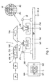
- FIG. 1 schematically depicts an example of an embodiment of a lithographic projection apparatus 1 according to the invention.
- the apparatus 1 typically comprises:
- the apparatus is of a reflective type (i.e. has a reflective mask). However, in general, it may also be of a transmissive type, for example (with a transmissive mask). Alternatively, the apparatus may employ another kind of patterning means, such as a programmable mirror array of a type as referred to above.
- the source LA (e.g. a Hg lamp, an excimer laser, an undulator or wiggler provided around the path of an electron beam in a storage ring or synchrotron, a laser-produced plasma source or otherwise) produces a beam of radiation.
- This beam is fed into an illumination system (illuminator) IL, either directly or after having traversed conditioning means, such as a beam expander Ex, for example.
- the illuminator IL may comprise adjusting means AM for setting the outer and/or inner radial extent (commonly referred to as ⁇ -outer and ⁇ -inner, respectively) of the intensity distribution in the beam.
- it will generally comprise various other components, such as an integrator IN and a condenser CO.
- the beam PB impinging on the mask MA has a desired uniformity and intensity distribution in its cross-section.
- the source LA may be within the housing of the lithographic projection apparatus (as is often the case when the source LA is a mercury lamp, for example), but that it may also be remote from the lithographic projection apparatus, the radiation beam which it produces being led into the apparatus (e.g. with the aid of suitable directing mirrors); this latter scenario is often the case when the source LA is an excimer laser.
- the current invention and claims encompass both of these scenarios.
- the beam PB subsequently intercepts the mask MA, which is held on a mask table MT. Having been selectively reflected by the mask MA, the beam PB passes through the projection system PL, which focuses the beam PB onto a target portion C of the substrate W. With the aid of the second positioning means PW (and interferometric measuring means IF), the substrate table WT can be moved accurately, e.g. so as to position different target portions C in the path of the beam PB. Similarly, the first positioning means PM can be used to accurately position the mask MA with respect to the path of the beam PB, e.g. after mechanical retrieval of the mask MA from a mask library, or during a scan.
- the mask table MT may just be connected to a short stroke actuator, or may be fixed.
- Mask MA and substrate W may be aligned using mask alignment marks M1, M2 and substrate alignment marks P1, P2.
- the depicted apparatus can be used in two different modes:
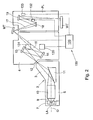
- FIG. 2 shows a projection system PL and a radiation system 2 which can be used in the example of a lithographic projection apparatus 1 of FIG. 1 .
- the radiation system 2 comprises an illumination optics unit 4.
- the radiation system may also comprise a source-collector module or radiation unit 3.
- the radiation unit 3 is provided with a radiation source LA which may be formed by a discharge plasma.
- the radiation source LA may employ a gas or vapor, such as Xe gas or Li vapor in which a very hot plasma may be created to emit radiation in the EUV range of the electromagnetic spectrum.
- the very hot plasma is created by causing a partially ionized plasma of an electrical discharge to collapse onto the optical axis O.
- Partial pressures of 0.1 mbar of Xe, Li vapor or any other suitable gas or vapor may be required for efficient generation of the radiation.
- the radiation emitted by radiation source LA is passed from the source chamber 7 into collector chamber 8 via a gas barrier structure or "foil trap" 9.
- the gas barrier structure comprises a channel structure such as, for instance, described in detail in European patent applications EP-A-1233 468 and EP-A-1 057 079 .
- the collector chamber 8 comprises a radiation collector 10 which can be formed by a grazing incidence collector. Radiation passed by collector 10 is reflected off a grating spectral filter 11 to be focused in a virtual source point 12 at an aperture in the collector chamber 8. From chamber 8, the projection beam 16 is reflected in illumination optics unit 4 via normal incidence reflectors 13, 14 onto a reticle or mask positioned on reticle or mask table MT. A patterned beam 17 is formed which is imaged in projection system PL via reflective elements 18, 19 onto a wafer stage or substrate table WT. More elements than shown may generally be present in illumination optics unit 4 and projection system PL.
- the example of a lithographic projection apparatus 1 according to an embodiment of the invention of FIG. 1 includes a purge gas supply system 100 according to the invention.
- Purge gas outlets 130-133 of the purge gas supply system 100 are positioned in the projection system PL and the radiation system 2 near the reflectors 13,14 and the reflective elements 18,19, as is shown in FIG. 2 .
- other parts of the apparatus may likewise be provided with a purge gas supply system according to an embodiment of the invention.
- a reticle and one or more sensors of the lithographic projection apparatus may be provided with a purge gas supply system according to the invention.
- the purge gas supply system 100 is positioned inside the lithographic projection apparatus 1 and the purge gas supply system 100 can be controlled in any manner suitable for the specific implementation using any convenient means outside the apparatus 1. However, it is likewise possible to position at least some parts of the purge gas supply system 100 outside the lithographic projection apparatus 1, such as for example the purge gas mixture generator 120 or otherwise.
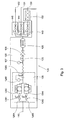
- FIG. 3 shows a practical example of a purge gas supply system 100.
- a similar system as shown in Fig. 3 may likewise be utilized in conditioning gas used in gas bearings in e.g. an immersion lithography apparatus.
- a purge gas inlet 110 is connected to a, not shown, purge gas supply apparatus which supplies a dry gas which is substantially without moisture, such as, for example, a pressurised gas supply circuit, a cylinder with compressed dry air or otherwise.
- the dry gas is fed through the purge gas mixture generator 120.
- the purge gas mixture generator 120 the dry gas is purified further, as is explained below in more detail.
- the purge gas mixture generator 120 includes a moisturiser 150 which adds a moisture to the dry gas, for some of the purge gas outlets 130-132.
- the moisturiser 150 is connected a single purge gas outlet 130.
- the other purge gas outlets 131,132 are not connected to the moisturiser 150.
- the purge gas outlet 130 a purge gas mixture comprising the purge gas and moisture is presented, whereas at the other purge gas outlets 131,132 only the dry purge gas is presented.
- the purge gas mixture may be provided only near surfaces provided with chemicals which require a moisture, such as the wafer table WT in the example of FIG. 1 , whereas other parts of the lithographic projection apparatus 1 can be provided with a 'dry' purge gas, i.e, without moisture.
- the moisture is added to a purge gas
- properties of the purge gas mixture such as the relative humidity or purity of the moisture
- the system is flexible, because the amount of moisture present in the purge gas mixture may easily be adjusted by adding more or less moisture to the purge gas.
- the purge gas mixture generator 120 in the example of FIG. 3 comprises, in a flow direction and that order: a purifier apparatus 128, a flow meter 127, a valve 125, a reducer 129, a heat exchanger 126 and a moisturiser 150.
- compressed dry air (CDA) from a, not shown, CDA source is supplied to the purifier apparatus 128 via the purge gas inlet 110.
- the CDA is purified by the purifier 128.
- the purifier 128 comprises two parallel flow branches 128A,128B each comprising, in the flow direction and that order: an automatic valve 1281,1282 and a regenerable purifier device 1283,1284.
- the regenerable purifier devices 1283,1284 are each provided with a heating element to heat and thereby regenerate the respective purifier device 1283,1284.
- the flow branches are connected downstream of the purifier devices 1283,1284 to a shut-off valve 1285 which is controlled by a purity sensor 1286.
- regenerable purifiers Because of the regenerable purifiers, the system can be used for a long time period by regenerating the purifiers in case they become saturated with the compounds removed from the purge gas.
- the regenerable purifiers may be of any suitable type, such as for example a, known as such, regenerable filter which removes contaminating compounds or particles out of a gas by means of a physical process, such as adsorption, catalysis or otherwise, as opposed to the, non regenerable, chemical processes occuring in a charcoal filter, for example.
- regenerable purifier does not contain organic material and the regenerable purifiers may for example contain a material suitable for physical binding a contaminant of the purge gas, such as for example: metals, zeolite, titanium oxides, gallium or palladium compounds, or otherwise.
- the purifier devices 1283,1284 are alternately put in a purifying state in which the CDA is purified and a regenerating state. In the regenerating state the purifier device is regenerated by means of the respective heating element. Thus, for example, while the purifier device 1283 purifies the CDA, the purifier device 1284 is regenerated.
- the purifier 128 can thus operate continuously while maintaining a constant level of purification.
- the automatic valves 1281,1282 are operated in correspondence with the operation of the corresponding purifier device 1283,1284. Thus, when a purifier device 1283,1284 is regenerated, the corresponding valve 1281,1282 is closed, while when a purifier device 1283,1284 is used to purify, the corresponding valve is open.
- the purified CDA is fed through the shut-off valve 1285 which is controlled by the purity sensor 1286, which is known per se and for the sake of brevity is not described in further detail.
- the purity sensor 1286 automatically closes the shut-off valve 1285 when the purity of the purified CDA is below a predetermined threshold value. Thus, contamination of the lithographic projection apparatus 1 with a purge gas with insufficient purity levels is prevented automatically.
- the flow of purified CDA can be monitored via the flow meter 127. Via the valve 125 the flow can be shut-off manually.
- the reducer 129 provides a stable pressure at the outlet of the reducer, thus a stable purge gas pressure is provided to restrictions (via the heat exchanger 126).
- the heat exchanger 126 provides a constant purified CDA temperature.
- the heat exchanger 126 extracts or adds heat to the purified CDA in order to achieve a gas temperature which is suitable for the specific implementation.
- stable processing conditions are required and the heat exchanger may thus stabilize the temperature of the purified CDA to have a gas temperature which is constant over time.
- Suitable conditions for the purge gas at the purge gas outlets are found to be: a flow of 20-30 standard litres per minute, and/or a temperature of the purge gas of about 22 degrees Celsius and/or a relative humidity in the range of 30-60%.
- the invention is not limited to these conditions and other values for these parameters may likewise be used in a system according to the invention.
- the heat exchanger 126 is connected via restrictions 143-145 to the purge gas outlets 130-132.
- the restrictions 143-145 limit the gas flow, such that at each of the purge gas outlets 130-132 a desired, fixed purge gas flow and pressure is obtained.
- a suitable value for the purge gas pressure at the purge gas outlets is for example 100 mbar. It is likewise possible to use adjustable restrictions to provide an adjustable gas flow at each of the purge gas outlets 130-132.
- the moisturiser 150 is connected downstream from the heat exchanger between the restriction 143 and the purge gas outlet 130.
- the purge gas outlet 130 is provided in the example of FIG. 1 and 2 near the wafer table WT.
- the moisturiser 150 adds a moisture to the purified CDA and thus provides a purge gas mixture to the outlet 130. In this example, only at a single outlet a purge gas mixture is discharged. However, it is likewise possible to discharge a purge gas mixture to two or more purge gas outlets, for example by connecting a multiple of purge gas outlets to separate moisturisers or connecting two or more outlets to the same moisturiser. It is likewise possible to provide a moisturiser at a different position in the purge gas mixture generator than is shown in FIG.
- the moisturiser 150 may be placed between the purge gas mixture generator 120 and the valve 143 instead of between the valve 143 and the purge gas outlet 130.
- the moisturizer 150 operates as a restriction as well and if so desired, the restriction 143 connected to the moisturiser 150 may be omitted.
- an additional heat exchanger (not shown) is provided at the purge gas outlet 130 for a better temperature control of the purge gas mixture.
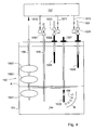
- the moisturiser 150 in FIG. 3 may for example be implemented as the example of FIG. 4 , however the moisturiser 150 may likewise be implemented differently, and for example comprise a vaporiser which vaporises a fluid into a flow of purge gas or otherwise.
- the moisturiser 150 shown in FIG. 4 comprises a liquid vessel 151 which is filled to a liquid level A with a liquid 154, such as high purity water for example.
- a gas inlet 1521 from hereon referred to as the wet gas inlet 1521, is placed mounding submerged in the liquid 154, that is below the liquid level A.
- Another gas inlet 1522 from hereon referred to as the dry gas inlet 1522, is placed mounding above the liquid level A, i.e. in the part of the liquid vessel 151 not filled with the liquid 154.
- a gas outlet 153 connects the part of the liquid vessel 153 above the liquid 154 with other parts of the purge gas supply system 100.
- a purge gas e.g.
- purified compressed dry air is fed into the liquid vessel 151 via the wet gas inlet 1521.
- bubbles 159 of purge gas are generated in the liquid 154. Due to buoyancy forces, the bubbles 159 travel upwards after mounding in the liquid 154, as indicated in FIG. 4 with arrow B. During this upwards travelling period, moisture from the liquid 154 enters the bubbles 159, for example due to diffusive processes or otherwise.
- the purge gas in the bubbles 159 is mixed with a moisture.
- the bubbles 159 supply their gaseous content to the gas(es) present in the liquid vessel 151 above the liquid 154.
- the resulting purge gas mixture is discharged from the vessel via the gas outlet 153.
- the wet gas inlet 1521 is a tubular element with an outside end connected outside the liquid vessel 151 to a, not shown, purge gas supply device, such as the purge gas mixture generator 120 of FIG. 3 , for example.
- the wet gas inlet 1521 is provided with a filter element 1525 with small, e.g. 0.5 micron, passages at an inside end which is positioned in the inside of the liquid vessel 151.
- the filter element 1525 is at least partially, (in this example entirely) placed in the liquid 154.
- the wet gas inlet 1521 generates a large amount of very small bubbles of purge gas. Because of their small size, in this example about 0.5 micron however other suitable dimensions may likewise be used, the bubbles 159 are moisturised to saturation in a relatively short time period, i.e. a relatively short travelling distance through the liquid 154.
- the dry gas inlet 1522 is provided with a filter element 1524 similar to the filter element of the wet gas inlet 1521.
- the gas flow through the wet gas inlet 1521 and the dry gas inlet 1522 is substantially similar, and the amount of moisture in the purge gas mixture is substantially half the amount of moisture in the bubbles 159 at the moment the bubbles 159 leave the liquid 154. That is, if the bubbles 159 are saturated with moisture, i.e. 100 % relative humidity (Rh), the purge gas mixture has a 50 % Rh.
- a purge gas mixture with a relative humidity above or equal to 20%, such as equal or more than 25% provides good results with respect to the performance of photo-resists. Furthermore, it is found that a purge gas mixture with a relative humidity equal or above 25% and below 70%, such as 60%, has a good preventive effect with respect to the accuracy of measurement systems in the lithographic projection apparatus. Furthermore, it was found that a humidity, e.g. about 40%, which is similar to the humidity in the space surrounding the lithographic projection apparatus, e.g. the cleanroom, provides optimal results.
- the gas outlet 153 is provided at its inside end with a fine-meshed, e.g. 0.003 micron, filter 1526 which filters particles and small droplets out of the gas flowing out of the liquid vessel 151. Thus, contamination of the surface to which the purge gas mixture is supplied by such particles is prevented.
- a fine-meshed, e.g. 0.003 micron, filter 1526 which filters particles and small droplets out of the gas flowing out of the liquid vessel 151.
- the relative amount of moisture in the purge gas mixture can be controlled in an uncomplicated manner, in different ways.
- parameters of the liquid vessel can be controlled.
- the amount of purge gas without moisture brought into the vessel 151 via the dry gas inlet 1522 relative to the amount of purge gas with moisture generated via the wet gas inlet 1521 can be controlled.
- the controlled parameters of the liquid vessel 151 may for example be one or more of: the inside temperature, flow, pressure, residence time of the purge gas in the liquid.
- the liquid vessel 151 may be provided with a heating element which is controlled by a control device in response to a temperature signal representing a temperature inside the liquid vessel provided by a temperature measuring device, for example.
- the residence time of the bubbles in the liquid 154 can be changed by adjusting the position at which the gas bubbles are inserted in the liquid via the wet gas inlet 1521. For example when the filter 1525 is positioned further into the liquid 154, the distance the bubbles have to travel to the liquid level A is increased and hence the residence time increases as well. The longer the gas bubbles are present in the liquid 154, the more moisture can be absorbed into the gas. Thus, by changing the residence time the humidity of the gas can be adapted.
- the moisturiser device 150 of FIG. 4 is further provided with a control device 157 via which the amount of moisture in the purge gas mixture can be controlled.
- the control device 157 is connected with a moisture control contact 1571 to a control valve 1523 in the dry gas inlet 1522 via which the flow rate of the purge gas supplied to the dry inlet 1522 can be controlled and therefore the amount of dry purge gas relative to the amount of moisturised gas.
- a humidity sensor (not shown) at the gas outlet 153, communicatively connected to the control device 157, provides to the control device 157 the humidity information of the purge gas mixture at the gas outlet 153. This information can be used by the control device 157 to adjust at least one of the parameters to control the amount of moisture in the purge gas mixture.
- the control device 157 further controls the amount of liquid 154 present in the liquid vessel 151.
- the control device 157 is connected with a liquid control contact 1572 to a control valve 1561 of a liquid supply 156 and with an overflow contact 1573 to a control valve 1531 of the gas outlet 153.
- a liquid level measuring device 158 is communicatively connected to the control device.
- the liquid level measuring device 158 provides a liquid level signal to the control device 157 which represents a property of the liquid level in the liquid vessel 151.
- the control device 157 operates the control valve 1561 and a control valve 1531 in response to the liquid level signal.
- the liquid level measuring device 158 comprises three float switches 1581-1583 positioned at suitable, different, heights with respect to the bottom of the liquid vessel 151.
- a lowest float switch 1581 is positioned nearest to the bottom.
- the lowest float switch 1581 provides an empty signal to the control device 157 when the liquid level A is at or below the lowest float switch 1581.
- the control devices 157 opens the control valve 1561 and automatically liquid is supplied to the vessel.
- the float switch 1582 in the middle provides a full signal in case the liquid level A reaches the height of this flow switch 1582.
- the control device 157 closes the control valve 1561 in response to the full signal and thereby turns off the liquid supply.
- a top float switch 1583 is positioned furthest away from the bottom.
- the top float switch 1583 provides an overfill signal to the control device 157 in case the liquid level A is at or above the top float switch 1581.
- the control device 157 shuts off the control valve 1531 of the gas outlet 153 to prevent leakage of the liquid into other parts of the lithographic projection apparatus 1.
Abstract
Claims (12)
- Un système d'amenée de gaz (100) pour fournir un gaz à au moins une partie d'un appareil de projection lithographique (1) comprenant un moyen de mesure interférométrique (IF, IF1), le gaz étant un gaz de purge, ledit système d'amenée de gaz comprenant :une entrée d'amenée de gaz (110) ; etune sortie de gaz (130) pour amener un mélange de gaz à ladite au moins une partie de l'appareil de projection lithographique, lequel mélange de gaz comprend au moins un gaz et une humidité ; etun générateur de mélange de gaz (120) arrangé pour générer le mélange de gaz, le générateur de mélange de gaz (120) étant pourvu d'un dispositif humidificateur (150) arrangé pour ajouter l'humidité à une partie du gaz de purge amené depuis l'entrée d'amenée de gaz (110),le système d'amenée de gaz (100) comprenant en outre une autre sortie de gaz (131, 132) arrangée pour fournir une autre partie du gaz de purge provenant de l'entrée d'amenée de gaz (110), substantiellement sans ajout d'humidité, à une autre partie de l'appareil de projection lithographique, etle mélange de gaz étant fourni par la sortie de gaz (130) à une partie de l'appareil lithographique (1) où le moyen de mesure interférométrique (IF, IF1) est configuré pour prendre des mesures interférométriques.
- Un appareil de projection lithographique (1) comprenant :un système de rayonnement pour fournir un faisceau de projection de rayonnement ;une structure formant support pour servir de support à un moyen pour conformer selon un motif, le moyen pour conformer selon un motif servant à conformer le faisceau de projection selon un motif souhaité ;une table porte-substrat (WT) pour porter un substrat ;un système de projection (PL) pour projeter le faisceau à motif sur une portion cible du substrat ;un moyen de mesure interférométrique (IF, IF1) ; etau moins un système d'amenée de gaz (100) selon la revendication 1.
- Un appareil de projection lithographique (1) tel que revendiqué dans la revendication 2, dans lequel le dispositif humidificateur (150) comprend :un récipient de liquide (151) avec au moins une admission de gaz (1521, 1522) et une sortie de gaz (153), lesdites admission de gaz et sortie de gaz étant raccordées l'une à l'autre via un raccordement humidifiant, si bien que dans le cas où un gaz de purge s'écoule à travers le raccordement humidifiant, ledit gaz de purge est introduit au travers d'un liquide (154) présent dans le récipient de liquide et ledit gaz de purge est humidifié.
- Un appareil de projection lithographique (1) tel que revendiqué dans la revendication 3, comprenant en outre une admission de gaz sec (1522) raccordée à la sortie de gaz, pour mélanger un gaz de purge non humidifié avec le gaz de purge humidifié introduit au travers du liquide (154) et obtenir de ce fait ledit mélange de gaz de purge.
- Un appareil de projection lithographique (1) tel que revendiqué dans la revendication 3 ou la revendication 4, dans lequel le raccordement humidifiant est un raccordement saturant pour introduire ledit gaz de purge au travers dudit liquide (154) de telle sorte que ledit gaz de purge soit humidifié jusqu'à saturation avec ladite humidité.
- Un appareil de projection lithographique (1) tel que revendiqué dans l'une quelconque des revendications 3 à 5, comprenant en outre un dispositif de contrôle (157) raccordé au récipient de liquide (151), pour contrôler au moins une quantité d'humidité présente dans le mélange de gaz de purge.
- Un appareil de projection lithographique (1) tel que revendiqué dans l'une quelconque des revendications 2 à 6, dans lequel le générateur de mélange de gaz de purge (120) comprend en outre un dispositif formant filtre régénérable (1283, 1284) pour éliminer par filtration au moins un composant non désiré d'au moins :soit le gaz de purge, soit l'humidité, soit le mélange de gaz de purge.
- Un appareil de projection lithographique tel que revendiqué dans la revendication 7, comprenant deux dispositifs formant filtres régénérables (1283, 1284) raccordés en parallèle, lesquels dispositifs formant filtres peuvent être régénérés en alternance pour permettre une filtration en continu.
- Un appareil de projection lithographique (1) tel que revendiqué dans l'une quelconque des revendications 2 à 8, dans lequel ladite humidité inclut de la vapeur d'eau.
- Un appareil de projection lithographique (1) tel que revendiqué dans la revendication 9, dans lequel ledit mélange de gaz de purge contient au moins 20 % HR de vapeur d'eau, et de préférence pas plus de 70 % HR.
- Un procédé pour fournir un gaz de purge à au moins une partie d'un appareil de projection lithographique (1), comprenant :un système de rayonnement pour fournir un faisceau de projection de rayonnement ;une structure formant support pour servir de support à un moyen pour conformer selon un motif, le moyen pour conformer selon un motif servant à conformer le faisceau de projection selon un motif souhaité ;une table porte-substrat (WT) pour porter un substrat ; etun système de projection (PL) pour projeter le faisceau à motif sur une portion cible du substrat ;un moyen de mesure interférométrique (IF, IF1) pour prendre des mesures interférométriques ;ledit procédé comprenant les étapes consistant à :amener un écoulement gazeux de gaz de purge composé d'au moins un gaz ;ajouter de l'humidité à une partie dudit écoulement gazeux pour former un mélange de gaz ;amener le mélange de gaz à au moins une partie de l'appareil de projection lithographique ;amener une autre partie dudit gaz de purge sans ajout d'humidité à une autre partie de l'appareil de projection lithographique pour purger ladite autre partie de l'appareil de projection lithographique,l'étape d'amener le mélange de gaz incluant le fait d'amener le mélange de gaz à une partie de l'appareil lithographique (1) où le moyen de mesure interférométrique (IF, IF1) est configuré pour prendre des mesures interférométriques.
- Un procédé de fabrication de dispositif, comprenant les étapes consistant à :fournir un substrat qui est au moins partiellement recouvert d'une couche de matériau sensible au rayonnement ;appliquer un procédé tel que revendiqué dans la revendication 11 à au moins une partie du substrat ;fournir un faisceau de projection de rayonnement ;utiliser un moyen pour conformer selon un motif afin de doter le faisceau de projection d'un motif dans sa coupe transversale ;projeter le faisceau de rayonnement à motif sur une portion cible de la couche de matériau sensible au rayonnement ;amener le mélange de gaz près d'une surface d'un composant utilisé dans le procédé de fabrication de dispositif.
Applications Claiming Priority (2)
| Application Number | Priority Date | Filing Date | Title |
|---|---|---|---|
| US10/623,180 US7384149B2 (en) | 2003-07-21 | 2003-07-21 | Lithographic projection apparatus, gas purging method and device manufacturing method and purge gas supply system |
| PCT/NL2004/000519 WO2005008339A2 (fr) | 2003-07-21 | 2004-07-20 | Appareil de projection lithographique, procede de drainage au gaz, procede de fabrication d'un dispositif et systeme d'approvisionnement en gaz de drainage |
Publications (2)
| Publication Number | Publication Date |
|---|---|
| EP1649325A2 EP1649325A2 (fr) | 2006-04-26 |
| EP1649325B1 true EP1649325B1 (fr) | 2012-01-11 |
Family
ID=34079792
Family Applications (3)
| Application Number | Title | Priority Date | Filing Date |
|---|---|---|---|
| EP04774827A Not-in-force EP1649325B1 (fr) | 2003-07-21 | 2004-07-20 | Appareil de projection lithographique, procede de drainage au gaz, procede de fabrication d'un dispositif et systeme d'approvisionnement en gaz de drainage |
| EP04757185A Expired - Fee Related EP1646915B1 (fr) | 2003-07-21 | 2004-07-21 | Procede d'humidification des gaz de purge et appareil de projection lithographique |
| EP10162412A Pending EP2211233A2 (fr) | 2003-07-21 | 2004-07-21 | Appareil de projection lithographique et procédé de purge de gaz |
Family Applications After (2)
| Application Number | Title | Priority Date | Filing Date |
|---|---|---|---|
| EP04757185A Expired - Fee Related EP1646915B1 (fr) | 2003-07-21 | 2004-07-21 | Procede d'humidification des gaz de purge et appareil de projection lithographique |
| EP10162412A Pending EP2211233A2 (fr) | 2003-07-21 | 2004-07-21 | Appareil de projection lithographique et procédé de purge de gaz |
Country Status (9)
| Country | Link |
|---|---|
| US (4) | US7384149B2 (fr) |
| EP (3) | EP1649325B1 (fr) |
| JP (4) | JP4487108B2 (fr) |
| KR (3) | KR100846184B1 (fr) |
| CN (3) | CN1853142B (fr) |
| DE (1) | DE602004027497D1 (fr) |
| SG (1) | SG141460A1 (fr) |
| TW (3) | TWI251130B (fr) |
| WO (2) | WO2005008339A2 (fr) |
Families Citing this family (111)
| Publication number | Priority date | Publication date | Assignee | Title |
|---|---|---|---|---|
| US9482966B2 (en) | 2002-11-12 | 2016-11-01 | Asml Netherlands B.V. | Lithographic apparatus and device manufacturing method |
| JP3953460B2 (ja) | 2002-11-12 | 2007-08-08 | エーエスエムエル ネザーランズ ビー.ブイ. | リソグラフィ投影装置 |
| US10503084B2 (en) | 2002-11-12 | 2019-12-10 | Asml Netherlands B.V. | Lithographic apparatus and device manufacturing method |
| CN100470367C (zh) | 2002-11-12 | 2009-03-18 | Asml荷兰有限公司 | 光刻装置和器件制造方法 |
| KR20050085235A (ko) | 2002-12-10 | 2005-08-29 | 가부시키가이샤 니콘 | 노광 장치 및 디바이스 제조 방법 |
| SG171468A1 (en) | 2002-12-10 | 2011-06-29 | Nikon Corp | Exposure apparatus and method for producing device |
| US7242455B2 (en) | 2002-12-10 | 2007-07-10 | Nikon Corporation | Exposure apparatus and method for producing device |
| CN1723541B (zh) | 2002-12-10 | 2010-06-02 | 株式会社尼康 | 曝光装置和器件制造方法 |
| US7948604B2 (en) | 2002-12-10 | 2011-05-24 | Nikon Corporation | Exposure apparatus and method for producing device |
| DE10261775A1 (de) | 2002-12-20 | 2004-07-01 | Carl Zeiss Smt Ag | Vorrichtung zur optischen Vermessung eines Abbildungssystems |
| KR101562447B1 (ko) | 2003-02-26 | 2015-10-21 | 가부시키가이샤 니콘 | 노광 장치, 노광 방법 및 디바이스 제조 방법 |
| WO2004086470A1 (fr) | 2003-03-25 | 2004-10-07 | Nikon Corporation | Systeme d'exposition et procede de production de dispositifs |
| EP1612850B1 (fr) | 2003-04-07 | 2009-03-25 | Nikon Corporation | Appareil d'exposition et procede pour fabrication d'un dispositif |
| KR20110104084A (ko) | 2003-04-09 | 2011-09-21 | 가부시키가이샤 니콘 | 액침 리소그래피 유체 제어 시스템 |
| SG141426A1 (en) | 2003-04-10 | 2008-04-28 | Nikon Corp | Environmental system including vacuum scavange for an immersion lithography apparatus |
| JP4488005B2 (ja) | 2003-04-10 | 2010-06-23 | 株式会社ニコン | 液浸リソグラフィ装置用の液体を捕集するための流出通路 |
| EP3352015A1 (fr) | 2003-04-10 | 2018-07-25 | Nikon Corporation | Système environnemental comprenant une zone de transport pour un appareil de lithographie par immersion |
| WO2004092830A2 (fr) | 2003-04-11 | 2004-10-28 | Nikon Corporation | Systeme de projection et de recuperation de liquides pour lithographie par immersion |
| CN101980087B (zh) | 2003-04-11 | 2013-03-27 | 株式会社尼康 | 浸没曝光设备以及浸没曝光方法 |
| SG2014015135A (en) | 2003-04-11 | 2015-06-29 | Nippon Kogaku Kk | Cleanup method for optics in immersion lithography |
| JP2006523958A (ja) | 2003-04-17 | 2006-10-19 | 株式会社ニコン | 液浸リソグラフィで使用するためのオートフォーカス素子の光学的構造 |
| TWI295414B (en) | 2003-05-13 | 2008-04-01 | Asml Netherlands Bv | Lithographic apparatus and device manufacturing method |
| TWI612556B (zh) | 2003-05-23 | 2018-01-21 | Nikon Corp | 曝光裝置、曝光方法及元件製造方法 |
| TW201515064A (zh) | 2003-05-23 | 2015-04-16 | 尼康股份有限公司 | 曝光方法及曝光裝置以及元件製造方法 |
| CN100541717C (zh) | 2003-05-28 | 2009-09-16 | 株式会社尼康 | 曝光方法、曝光装置以及器件制造方法 |
| US7189291B2 (en) * | 2003-06-02 | 2007-03-13 | Entegris, Inc. | Method for the removal of airborne molecular contaminants using oxygen gas mixtures |
| US7213963B2 (en) | 2003-06-09 | 2007-05-08 | Asml Netherlands B.V. | Lithographic apparatus and device manufacturing method |
| US7684008B2 (en) | 2003-06-11 | 2010-03-23 | Asml Netherlands B.V. | Lithographic apparatus and device manufacturing method |
| TW201818451A (zh) | 2003-06-13 | 2018-05-16 | 日商尼康股份有限公司 | 曝光裝置、元件製造方法 |
| KR101674329B1 (ko) | 2003-06-19 | 2016-11-08 | 가부시키가이샤 니콘 | 노광 장치 및 디바이스 제조방법 |
| EP2466382B1 (fr) | 2003-07-08 | 2014-11-26 | Nikon Corporation | Table support de tranches pour lithographie en immersion |
| EP2264532B1 (fr) | 2003-07-09 | 2012-10-31 | Nikon Corporation | Appareil d'exposition et procédé de fabrication d'un dispositif |
| KR20060026883A (ko) | 2003-07-09 | 2006-03-24 | 가부시키가이샤 니콘 | 결합장치, 노광장치 및 디바이스 제조방법 |
| WO2005006418A1 (fr) | 2003-07-09 | 2005-01-20 | Nikon Corporation | Dispositif d'exposition et procede de fabrication |
| US20060285091A1 (en) * | 2003-07-21 | 2006-12-21 | Parekh Bipin S | Lithographic projection apparatus, gas purging method, device manufacturing method and purge gas supply system related application |
| US7384149B2 (en) * | 2003-07-21 | 2008-06-10 | Asml Netherlands B.V. | Lithographic projection apparatus, gas purging method and device manufacturing method and purge gas supply system |
| WO2005010960A1 (fr) | 2003-07-25 | 2005-02-03 | Nikon Corporation | Systeme d'inspection , dispositif d'inspection et procede de production pour systeme de projection optique |
| US7175968B2 (en) | 2003-07-28 | 2007-02-13 | Asml Netherlands B.V. | Lithographic apparatus, device manufacturing method and a substrate |
| EP1503244A1 (fr) | 2003-07-28 | 2005-02-02 | ASML Netherlands B.V. | Appareil de projection lithographique et méthode de fabrication d'un dispositif |
| CN102043350B (zh) | 2003-07-28 | 2014-01-29 | 株式会社尼康 | 曝光装置、器件制造方法、及曝光装置的控制方法 |
| US7779781B2 (en) | 2003-07-31 | 2010-08-24 | Asml Netherlands B.V. | Lithographic apparatus and device manufacturing method |
| EP2804048A1 (fr) | 2003-08-29 | 2014-11-19 | Nikon Corporation | Appareil d'exposition et procédé de production d'un dispositif |
| TWI263859B (en) | 2003-08-29 | 2006-10-11 | Asml Netherlands Bv | Lithographic apparatus and device manufacturing method |
| KR101238114B1 (ko) | 2003-09-03 | 2013-02-27 | 가부시키가이샤 니콘 | 액침 리소그래피용 유체를 제공하기 위한 장치 및 방법 |
| WO2005029559A1 (fr) | 2003-09-19 | 2005-03-31 | Nikon Corporation | Appareil d'insolation et procede permettant de produire un dispositif |
| TW200518187A (en) | 2003-09-29 | 2005-06-01 | Nikon Corp | Exposure apparatus, exposure method, and device manufacturing method |
| EP1672681B8 (fr) | 2003-10-08 | 2011-09-21 | Miyagi Nikon Precision Co., Ltd. | Appareil d'exposition, procede de transport de substrat, procede d'exposition, et procede de production d'un dispositif |
| EP1672682A4 (fr) | 2003-10-08 | 2008-10-15 | Zao Nikon Co Ltd | Appareil et procede de transport de substrat, appareil et procede d'exposition, et procede de production de dispositif |
| TW201738932A (zh) | 2003-10-09 | 2017-11-01 | Nippon Kogaku Kk | 曝光裝置及曝光方法、元件製造方法 |
| US7411653B2 (en) | 2003-10-28 | 2008-08-12 | Asml Netherlands B.V. | Lithographic apparatus |
| US7352433B2 (en) | 2003-10-28 | 2008-04-01 | Asml Netherlands B.V. | Lithographic apparatus and device manufacturing method |
| JP4295712B2 (ja) | 2003-11-14 | 2009-07-15 | エーエスエムエル ネザーランズ ビー.ブイ. | リソグラフィ装置及び装置製造方法 |
| KR101394764B1 (ko) | 2003-12-03 | 2014-05-27 | 가부시키가이샤 니콘 | 노광 장치, 노광 방법 및 디바이스 제조 방법, 그리고 광학 부품 |
| CN100487860C (zh) | 2003-12-15 | 2009-05-13 | 株式会社尼康 | 台装置、曝光装置和曝光方法 |
| US7394521B2 (en) | 2003-12-23 | 2008-07-01 | Asml Netherlands B.V. | Lithographic apparatus and device manufacturing method |
| ATE459898T1 (de) | 2004-01-20 | 2010-03-15 | Zeiss Carl Smt Ag | Belichtungsvorrichtung und messeinrichtung für eine projektionslinse |
| US7589822B2 (en) | 2004-02-02 | 2009-09-15 | Nikon Corporation | Stage drive method and stage unit, exposure apparatus, and device manufacturing method |
| KR101227211B1 (ko) | 2004-02-03 | 2013-01-28 | 가부시키가이샤 니콘 | 노광 장치 및 디바이스 제조 방법 |
| KR101441777B1 (ko) | 2004-03-25 | 2014-09-22 | 가부시키가이샤 니콘 | 노광 장치 및 디바이스 제조 방법 |
| US7898642B2 (en) | 2004-04-14 | 2011-03-01 | Asml Netherlands B.V. | Lithographic apparatus and device manufacturing method |
| EP1747499A2 (fr) | 2004-05-04 | 2007-01-31 | Nikon Corporation | Appareil et procede d'approvisionnement en fluide pour la lithographie par immersion |
| US7616383B2 (en) | 2004-05-18 | 2009-11-10 | Asml Netherlands B.V. | Lithographic apparatus and device manufacturing method |
| CN101833247B (zh) | 2004-06-04 | 2013-11-06 | 卡尔蔡司Smt有限责任公司 | 微光刻投影曝光系统的投影物镜的光学测量的测量系统 |
| KR101512884B1 (ko) | 2004-06-09 | 2015-04-16 | 가부시키가이샤 니콘 | 노광 장치 및 디바이스 제조 방법 |
| US7463330B2 (en) | 2004-07-07 | 2008-12-09 | Asml Netherlands B.V. | Lithographic apparatus and device manufacturing method |
| ATE441937T1 (de) | 2004-07-12 | 2009-09-15 | Nikon Corp | Belichtungsgerät und bauelemente- herstellungsverfahren |
| KR20070048164A (ko) | 2004-08-18 | 2007-05-08 | 가부시키가이샤 니콘 | 노광 장치 및 디바이스 제조 방법 |
| US7701550B2 (en) | 2004-08-19 | 2010-04-20 | Asml Netherlands B.V. | Lithographic apparatus and device manufacturing method |
| US7397533B2 (en) | 2004-12-07 | 2008-07-08 | Asml Netherlands B.V. | Lithographic apparatus and device manufacturing method |
| US7880860B2 (en) | 2004-12-20 | 2011-02-01 | Asml Netherlands B.V. | Lithographic apparatus and device manufacturing method |
| SG124351A1 (en) | 2005-01-14 | 2006-08-30 | Asml Netherlands Bv | Lithographic apparatus and device manufacturing method |
| SG124359A1 (en) | 2005-01-14 | 2006-08-30 | Asml Netherlands Bv | Lithographic apparatus and device manufacturing method |
| US8692973B2 (en) | 2005-01-31 | 2014-04-08 | Nikon Corporation | Exposure apparatus and method for producing device |
| EP3079164A1 (fr) | 2005-01-31 | 2016-10-12 | Nikon Corporation | Appareil d'exposition et procédé de production d'un dispositif |
| US7282701B2 (en) | 2005-02-28 | 2007-10-16 | Asml Netherlands B.V. | Sensor for use in a lithographic apparatus |
| US20060199274A1 (en) * | 2005-03-01 | 2006-09-07 | Canon Kabushiki Kaisha | Atmosphere conditioning method, exposure apparatus, and device manufacturing method |
| JP4072543B2 (ja) * | 2005-03-18 | 2008-04-09 | キヤノン株式会社 | 液浸露光装置及びデバイス製造方法 |
| USRE43576E1 (en) | 2005-04-08 | 2012-08-14 | Asml Netherlands B.V. | Dual stage lithographic apparatus and device manufacturing method |
| WO2007019105A1 (fr) * | 2005-08-03 | 2007-02-15 | Entegris, Inc. | Conteneur de transfert |
| US7986395B2 (en) * | 2005-10-24 | 2011-07-26 | Taiwan Semiconductor Manufacturing Company, Ltd. | Immersion lithography apparatus and methods |
| US7420194B2 (en) | 2005-12-27 | 2008-09-02 | Asml Netherlands B.V. | Lithographic apparatus and substrate edge seal |
| US7528387B2 (en) * | 2005-12-29 | 2009-05-05 | Interuniversitair Microelektronica Centrum (Imec) | Methods and systems for characterising and optimising immersion lithographic processing |
| US7649611B2 (en) | 2005-12-30 | 2010-01-19 | Asml Netherlands B.V. | Lithographic apparatus and device manufacturing method |
| US7253875B1 (en) * | 2006-03-03 | 2007-08-07 | Asml Netherlands B.V. | Lithographic apparatus and device manufacturing method |
| JP5567327B2 (ja) | 2006-04-03 | 2014-08-06 | インテグリス・インコーポレーテッド | 常圧マイクロ波プラズマ処理多孔性膜 |
| DE102006021797A1 (de) | 2006-05-09 | 2007-11-15 | Carl Zeiss Smt Ag | Optische Abbildungseinrichtung mit thermischer Dämpfung |
| CN101506087B (zh) | 2006-06-19 | 2011-09-21 | 诚实公司 | 用于净化光罩存储器的系统 |
| US8564759B2 (en) * | 2006-06-29 | 2013-10-22 | Taiwan Semiconductor Manufacturing Company, Ltd. | Apparatus and method for immersion lithography |
| US7933000B2 (en) * | 2006-11-16 | 2011-04-26 | Asml Netherlands B.V. | Device manufacturing method, method for holding a patterning device and lithographic apparatus including an applicator for applying molecules onto a clamp area of a patterning device |
| US7866637B2 (en) * | 2007-01-26 | 2011-01-11 | Asml Netherlands B.V. | Humidifying apparatus, lithographic apparatus and humidifying method |
| US8817226B2 (en) | 2007-02-15 | 2014-08-26 | Asml Holding N.V. | Systems and methods for insitu lens cleaning using ozone in immersion lithography |
| US8654305B2 (en) | 2007-02-15 | 2014-02-18 | Asml Holding N.V. | Systems and methods for insitu lens cleaning in immersion lithography |
| US8237911B2 (en) | 2007-03-15 | 2012-08-07 | Nikon Corporation | Apparatus and methods for keeping immersion fluid adjacent to an optical assembly during wafer exchange in an immersion lithography machine |
| NL1036181A1 (nl) * | 2007-11-30 | 2009-06-04 | Asml Netherlands Bv | A lithographic apparatus, a projection system and a device manufacturing method. |
| US9176393B2 (en) | 2008-05-28 | 2015-11-03 | Asml Netherlands B.V. | Lithographic apparatus and a method of operating the apparatus |
| CN102481524B (zh) * | 2009-08-21 | 2014-06-18 | 东丽株式会社 | 水蒸气透过性膜、中空纱膜和中空纱膜组件 |
| TWI450324B (zh) * | 2010-01-25 | 2014-08-21 | Gudeng Prec Ind Co Ltd | 微影設備之光罩清潔方法及微影設備之光罩清潔系統 |
| EP2381310B1 (fr) | 2010-04-22 | 2015-05-06 | ASML Netherlands BV | Structure de manipulation de fluide et appareil lithographique |
| KR101814854B1 (ko) * | 2010-12-28 | 2018-01-04 | 도레이 카부시키가이샤 | 의료 재료 및 중공사막 모듈 |
| GB2502476A (en) * | 2011-02-15 | 2013-11-27 | Schlumberger Holdings | Method and apparatus for protecting downhole components with inert atmosphere |
| NL2009305A (en) * | 2011-08-31 | 2013-03-04 | Asml Netherlands Bv | A method of determining focus corrections, lithographic processing cell and device manufacturing method. |
| KR102227564B1 (ko) * | 2014-01-20 | 2021-03-15 | 삼성디스플레이 주식회사 | 포토레지스트 조성물 |
| US10005018B2 (en) * | 2016-09-02 | 2018-06-26 | Battelle Memorial Institute | Xenon collection method and system |
| JP6767257B2 (ja) * | 2016-12-22 | 2020-10-14 | 東京エレクトロン株式会社 | 基板処理装置及び基板処理方法 |
| JP7193459B2 (ja) | 2017-01-06 | 2022-12-20 | エーエスエムエル ネザーランズ ビー.ブイ. | 極端紫外線源(euv源) |
| DE102017207030A1 (de) * | 2017-04-26 | 2018-10-31 | Carl Zeiss Smt Gmbh | Verfahren zur Reinigung von optischen Elementen für den ultravioletten Wellenlängenbereich |
| US11626285B2 (en) * | 2019-09-10 | 2023-04-11 | Taiwan Semiconductor Manufacturing Co., Ltd. | Method of manufacturing a semiconductor device |
| KR20210053633A (ko) * | 2019-11-04 | 2021-05-12 | 허니웰 인터내셔널 인코포레이티드 | 가스 감지에서 잘못된 알람 이벤트를 검출하기 위한 방법 및 시스템 |
| EP3832391A1 (fr) * | 2019-12-03 | 2021-06-09 | ASML Netherlands B.V. | Ensemble de serrage |
| DE102020204545A1 (de) * | 2020-04-08 | 2021-10-14 | Carl Zeiss Smt Gmbh | Verfahren und vorrichtung zum trocknen eines bauteilinnenraums |
| DE102023200132A1 (de) | 2022-05-04 | 2023-11-09 | Carl Zeiss Smt Gmbh | Einrichtung zur Entfernung von gasförmigen Kontaminationen und Vorrichtung, insbesondere Lithographiesystem, mit einer solchen Einrichtung |
Citations (3)
| Publication number | Priority date | Publication date | Assignee | Title |
|---|---|---|---|---|
| EP1126323A2 (fr) * | 2000-02-15 | 2001-08-22 | Nikon Corporation | Méthode d'exposition et appareil d'exposition |
| US6432204B1 (en) * | 2000-05-17 | 2002-08-13 | Tokyo Electron Limited | Temperature and humidity controlled processing system |
| US6545746B1 (en) * | 1996-03-04 | 2003-04-08 | Nikon Corporation | Projection exposure apparatus |
Family Cites Families (69)
| Publication number | Priority date | Publication date | Assignee | Title |
|---|---|---|---|---|
| DE19910441C1 (de) * | 1999-03-10 | 2000-06-21 | Fraunhofer Ges Forschung | Luftbefeuchtung |
| DE2964203D1 (en) * | 1978-07-12 | 1983-01-13 | Jackson Richard R | Nested hollow fiber humidifier |
| DD160756A3 (de) * | 1981-04-24 | 1984-02-29 | Gudrun Dietz | Anordnung zur verbesserung fotochemischer umsetzungsprozesse in fotoresistschichten |
| JPS62130321U (fr) | 1986-02-07 | 1987-08-18 | ||
| US4902456A (en) | 1988-05-04 | 1990-02-20 | Millipore Corporation | Fluorocarbon membranes and process for making fluorocarbon membranes |
| US5523193A (en) | 1988-05-31 | 1996-06-04 | Texas Instruments Incorporated | Method and apparatus for patterning and imaging member |
| DE59105735D1 (de) | 1990-05-02 | 1995-07-20 | Fraunhofer Ges Forschung | Belichtungsvorrichtung. |
| US5229872A (en) | 1992-01-21 | 1993-07-20 | Hughes Aircraft Company | Exposure device including an electrically aligned electronic mask for micropatterning |
| JPH0636993A (ja) * | 1992-05-21 | 1994-02-10 | Canon Inc | 露光装置及び半導体素子の製造方法 |
| US5240472A (en) * | 1992-05-29 | 1993-08-31 | Air Products And Chemicls, Inc. | Moisture removal from a wet gas |
| US5348691A (en) * | 1993-06-11 | 1994-09-20 | United Technologies Corporation | Atmosphere membrane humidifier and method and system for producing humidified air |
| IT1264661B1 (it) | 1993-07-05 | 1996-10-04 | Ausimont Spa | Copolimeri termoprocessabilin del tetrafluoroetilene |
| US5996976A (en) * | 1993-07-13 | 1999-12-07 | Lynntech, Inc. | Gas humidification system using water permeable membranes |
| JP3500619B2 (ja) * | 1993-10-28 | 2004-02-23 | 株式会社ニコン | 投影露光装置 |
| US5528905A (en) | 1994-03-25 | 1996-06-25 | Essex Invention S.A. | Contactor, particularly a vapour exchanger for the control of the air hygrometric content, and a device for air handling |
| EP0882493A3 (fr) | 1994-06-22 | 1999-06-30 | Fls Miljo A/S | Procédé de transfert de masse |
| JPH08266631A (ja) * | 1995-03-31 | 1996-10-15 | Asahi Glass Co Ltd | 呼吸用気体の加湿装置 |
| WO1997033205A1 (fr) | 1996-03-06 | 1997-09-12 | Philips Electronics N.V. | Systeme d'interferometre differentiel et dispositif lithographique a balayage par etapes pourvu d'un tel systeme |
| KR100542414B1 (ko) * | 1996-03-27 | 2006-05-10 | 가부시키가이샤 니콘 | 노광장치및공조장치 |
| JPH09275054A (ja) * | 1996-04-03 | 1997-10-21 | Nikon Corp | 半導体製造装置 |
| KR100512450B1 (ko) | 1996-12-24 | 2006-01-27 | 에이에스엠엘 네델란즈 비.브이. | 두개의물체홀더를가진이차원적으로안정화된위치설정장치와이런위치설정장치를구비한리소그래픽장치 |
| AU2048097A (en) | 1997-01-29 | 1998-08-18 | Micronic Laser Systems Ab | Method and apparatus for the production of a structure by focused laser radiation on a photosensitively coated substrate |
| SE509062C2 (sv) | 1997-02-28 | 1998-11-30 | Micronic Laser Systems Ab | Dataomvandlingsmetod för en laserskrivare med flera strålar för mycket komplexa mikrokolitografiska mönster |
| USRE40043E1 (en) | 1997-03-10 | 2008-02-05 | Asml Netherlands B.V. | Positioning device having two object holders |
| EP1014429A4 (fr) * | 1997-04-18 | 2000-07-19 | Nikon Corp | Procede et dispositif de commande de l'exposition, procede et dispositif d'exposition, et procede de fabrication dudit dispositif |
| US5910292A (en) * | 1997-08-19 | 1999-06-08 | Aeronex, Inc. | Method for water removal from corrosive gas streams |
| US6059859A (en) * | 1997-09-19 | 2000-05-09 | Aeronex, Inc. | Method, composition and apparatus for water removal from non-corrosive gas streams |
| NL1008352C2 (nl) | 1998-02-19 | 1999-08-20 | Stichting Tech Wetenschapp | Inrichting, geschikt voor extreem ultraviolet lithografie, omvattende een stralingsbron en een verwerkingsorgaan voor het verwerken van de van de stralingsbron afkomstige straling, alsmede een filter voor het onderdrukken van ongewenste atomaire en microscopische deeltjes welke door een stralingsbron zijn uitgezonden. |
| US6089282A (en) * | 1998-05-08 | 2000-07-18 | Aeronex, Inc. | Method for recovery and reuse of gas |
| DE69934701T2 (de) * | 1998-09-09 | 2007-11-15 | Pall Corp. | Verfahren zur Behandlung von Fluida |
| US6254936B1 (en) * | 1998-09-14 | 2001-07-03 | Silicon Valley Group, Inc. | Environment exchange control for material on a wafer surface |
| US6235641B1 (en) | 1998-10-30 | 2001-05-22 | Fsi International Inc. | Method and system to control the concentration of dissolved gas in a liquid |
| US6582496B1 (en) * | 2000-01-28 | 2003-06-24 | Mykrolis Corporation | Hollow fiber membrane contactor |
| JP4514959B2 (ja) * | 1999-01-29 | 2010-07-28 | マイクロリス・コーポレイション | 中空繊維膜の製造方法 |
| DE60029087T2 (de) * | 1999-01-29 | 2007-05-31 | Entegris, Inc., Chaska | Stoffaustauschapparat mit hohlfibermembran |
| US6802972B1 (en) * | 1999-01-29 | 2004-10-12 | Mykrolis Corporation | Microporous hollow fiber membranes from perfluorinated thermoplastic polymers |
| US6149817A (en) | 1999-03-08 | 2000-11-21 | Celgard Inc. | Shell-less hollow fiber membrane fluid contactor |
| US6394109B1 (en) * | 1999-04-13 | 2002-05-28 | Applied Materials, Inc. | Method and apparatus for removing carbon contamination in a sub-atmospheric charged particle beam lithography system |
| AU4949900A (en) * | 1999-05-28 | 2000-12-18 | Nikon Corporation | Exposure method and apparatus |
| JP3927344B2 (ja) * | 2000-01-19 | 2007-06-06 | 本田技研工業株式会社 | 加湿装置 |
| JP3869999B2 (ja) * | 2000-03-30 | 2007-01-17 | キヤノン株式会社 | 露光装置および半導体デバイス製造方法 |
| US6402818B1 (en) | 2000-06-02 | 2002-06-11 | Celgard Inc. | Degassing a liquid with a membrane contactor |
| JP2001349585A (ja) | 2000-06-07 | 2001-12-21 | Orion Mach Co Ltd | 吸湿性中空繊維を使用する高分子膜加湿器 |
| JP2001358055A (ja) | 2000-06-15 | 2001-12-26 | Nikon Corp | 露光装置及びデバイス製造方法 |
| US6305097B1 (en) * | 2000-06-29 | 2001-10-23 | Texas Instruments Incorporated | Apparatus for in-situ reticle cleaning at photolithography tool |
| JP2002158170A (ja) * | 2000-09-08 | 2002-05-31 | Nikon Corp | 露光装置及びデバイス製造方法 |
| JP4610715B2 (ja) * | 2000-11-06 | 2011-01-12 | Nok株式会社 | 加湿装置 |
| JP2002158154A (ja) * | 2000-11-16 | 2002-05-31 | Canon Inc | 露光装置 |
| DE10059910C2 (de) * | 2000-12-01 | 2003-01-16 | Daimler Chrysler Ag | Vorrichtung zur kontinuierlichen Befeuchtung und Entfeuchtung der Zuluft von Fertigungsprozessen oder Raumlufttechnik-Anlagen |
| US20020136939A1 (en) | 2001-02-15 | 2002-09-26 | Grieve M. James | Fuel cell and battery voltage controlling method and system |
| JP3765531B2 (ja) | 2001-03-30 | 2006-04-12 | 本田技研工業株式会社 | 加湿モジュール |
| US6391090B1 (en) | 2001-04-02 | 2002-05-21 | Aeronex, Inc. | Method for purification of lens gases used in photolithography |
| US6842998B2 (en) * | 2001-04-06 | 2005-01-18 | Akrion Llc | Membrane dryer |
| US6616841B2 (en) | 2001-06-21 | 2003-09-09 | Celgard Inc. | Hollow fiber membrane contactor |
| US6514313B1 (en) * | 2001-06-22 | 2003-02-04 | Aeronex, Inc. | Gas purification system and method |
| US6724460B2 (en) * | 2001-11-19 | 2004-04-20 | Asml Netherlands B.V. | Lithographic projection apparatus, device manufacturing method, device manufactured thereby, cleaning unit and method of cleaning contaminated objects |
| US6828569B2 (en) * | 2001-11-19 | 2004-12-07 | Asml Netherlands B.V. | Lithographic projection apparatus, device manufacturing method and device manufactured thereby |
| US20030162305A1 (en) * | 2002-02-25 | 2003-08-28 | Daniel Alvarez | Gas contaminant detection and quantification method |
| US6638341B1 (en) * | 2002-06-14 | 2003-10-28 | Aeronex, Inc. | Method for rapid activation or preconditioning of porous gas purification substrates |
| US7455721B2 (en) * | 2002-07-18 | 2008-11-25 | Daimler Ag | Device and method for humidifying a gas flow |
| KR101101737B1 (ko) | 2002-12-10 | 2012-01-05 | 가부시키가이샤 니콘 | 노광장치 및 노광방법, 디바이스 제조방법 |
| KR20050103946A (ko) * | 2003-02-21 | 2005-11-01 | 마이크롤리스 코포레이션 | 정화제 정보 탐색 시스템 |
| US7189291B2 (en) * | 2003-06-02 | 2007-03-13 | Entegris, Inc. | Method for the removal of airborne molecular contaminants using oxygen gas mixtures |
| US6867844B2 (en) | 2003-06-19 | 2005-03-15 | Asml Holding N.V. | Immersion photolithography system and method using microchannel nozzles |
| US7384149B2 (en) * | 2003-07-21 | 2008-06-10 | Asml Netherlands B.V. | Lithographic projection apparatus, gas purging method and device manufacturing method and purge gas supply system |
| US20060285091A1 (en) | 2003-07-21 | 2006-12-21 | Parekh Bipin S | Lithographic projection apparatus, gas purging method, device manufacturing method and purge gas supply system related application |
| US7779781B2 (en) * | 2003-07-31 | 2010-08-24 | Asml Netherlands B.V. | Lithographic apparatus and device manufacturing method |
| US7701550B2 (en) | 2004-08-19 | 2010-04-20 | Asml Netherlands B.V. | Lithographic apparatus and device manufacturing method |
| US11206499B2 (en) | 2016-08-18 | 2021-12-21 | Qualcomm Incorporated | Hearable device comprising integrated device and wireless functionality |
-
2003
- 2003-07-21 US US10/623,180 patent/US7384149B2/en not_active Expired - Lifetime
-
2004
- 2004-07-20 JP JP2006521023A patent/JP4487108B2/ja active Active
- 2004-07-20 US US10/894,365 patent/US7113254B2/en not_active Expired - Lifetime
- 2004-07-20 TW TW093121654A patent/TWI251130B/zh active
- 2004-07-20 WO PCT/NL2004/000519 patent/WO2005008339A2/fr active Application Filing
- 2004-07-20 CN CN2004800266052A patent/CN1853142B/zh active Active
- 2004-07-20 KR KR1020067001345A patent/KR100846184B1/ko not_active IP Right Cessation
- 2004-07-20 EP EP04774827A patent/EP1649325B1/fr not_active Not-in-force
- 2004-07-21 US US10/565,486 patent/US7879137B2/en not_active Expired - Fee Related
- 2004-07-21 CN CN2007101812213A patent/CN101144986B/zh not_active Expired - Fee Related
- 2004-07-21 KR KR1020077023567A patent/KR20070106805A/ko active IP Right Grant
- 2004-07-21 SG SG200802367-3A patent/SG141460A1/en unknown
- 2004-07-21 WO PCT/US2004/023490 patent/WO2005010619A2/fr active Application Filing
- 2004-07-21 EP EP04757185A patent/EP1646915B1/fr not_active Expired - Fee Related
- 2004-07-21 KR KR1020067001321A patent/KR101077683B1/ko not_active IP Right Cessation
- 2004-07-21 TW TW093121732A patent/TW200511389A/zh unknown
- 2004-07-21 JP JP2006521216A patent/JP2006528431A/ja not_active Withdrawn
- 2004-07-21 DE DE602004027497T patent/DE602004027497D1/de active Active
- 2004-07-21 CN CN200480021018A patent/CN100590530C/zh not_active Expired - Fee Related
- 2004-07-21 EP EP10162412A patent/EP2211233A2/fr active Pending
- 2004-07-21 TW TW096131640A patent/TW200801848A/zh unknown
-
2006
- 2006-09-25 US US11/525,934 patent/US7450215B2/en not_active Expired - Lifetime
-
2007
- 2007-11-19 JP JP2007299182A patent/JP2008160080A/ja not_active Withdrawn
-
2011
- 2011-10-27 JP JP2011235682A patent/JP2012074712A/ja not_active Withdrawn
Patent Citations (3)
| Publication number | Priority date | Publication date | Assignee | Title |
|---|---|---|---|---|
| US6545746B1 (en) * | 1996-03-04 | 2003-04-08 | Nikon Corporation | Projection exposure apparatus |
| EP1126323A2 (fr) * | 2000-02-15 | 2001-08-22 | Nikon Corporation | Méthode d'exposition et appareil d'exposition |
| US6432204B1 (en) * | 2000-05-17 | 2002-08-13 | Tokyo Electron Limited | Temperature and humidity controlled processing system |
Also Published As
Similar Documents
| Publication | Publication Date | Title |
|---|---|---|
| EP1649325B1 (fr) | Appareil de projection lithographique, procede de drainage au gaz, procede de fabrication d'un dispositif et systeme d'approvisionnement en gaz de drainage | |
| US7315346B2 (en) | Lithographic apparatus and device manufacturing method | |
| EP1312983B1 (fr) | Photonettoyage | |
| US7115886B2 (en) | Lithographic projection apparatus, device manufacturing method and device manufactured thereby | |
| US7026629B2 (en) | Lithographic apparatus and device manufacturing method | |
| EP1429189B1 (fr) | Appareil lithographique et méthode de fabrication d'un dispositif | |
| EP1447716A2 (fr) | Appareil lithographique avec système de purge par gaz | |
| JP2008004969A (ja) | リソグラフィ装置およびデバイス製造方法 | |
| US6847430B2 (en) | Lithographic apparatus and device manufacturing method | |
| EP1160627A2 (fr) | Appareil lithographique, méthode de fabrication d'un dispositif et dispositif fabriqué par cette méthode | |
| KR101583644B1 (ko) | 자석을 포함하는 리소그래피 장치, 리소그래피 장치에서 자석의 보호를 위한 방법, 및 디바이스 제조 방법 | |
| EP1503243A1 (fr) | Appareil lithographique, méthode de fabrication d'un dispositif et dispositif fabriqué par cette méthode |
Legal Events
| Date | Code | Title | Description |
|---|---|---|---|
| PUAI | Public reference made under article 153(3) epc to a published international application that has entered the european phase |
Free format text: ORIGINAL CODE: 0009012 |
|
| 17P | Request for examination filed |
Effective date: 20060220 |
|
| AK | Designated contracting states |
Kind code of ref document: A2 Designated state(s): DE FR GB IT NL |
|
| RAP1 | Party data changed (applicant data changed or rights of an application transferred) |
Owner name: ENTEGRIS, INC. Owner name: ASML NETHERLANDS B.V. |
|
| DAX | Request for extension of the european patent (deleted) | ||
| RBV | Designated contracting states (corrected) |
Designated state(s): DE FR GB IT NL |
|
| GRAP | Despatch of communication of intention to grant a patent |
Free format text: ORIGINAL CODE: EPIDOSNIGR1 |
|
| GRAS | Grant fee paid |
Free format text: ORIGINAL CODE: EPIDOSNIGR3 |
|
| GRAA | (expected) grant |
Free format text: ORIGINAL CODE: 0009210 |
|
| AK | Designated contracting states |
Kind code of ref document: B1 Designated state(s): DE FR GB IT NL |
|
| REG | Reference to a national code |
Ref country code: GB Ref legal event code: FG4D |
|
| REG | Reference to a national code |
Ref country code: DE Ref legal event code: R096 Ref document number: 602004036112 Country of ref document: DE Effective date: 20120308 |
|
| REG | Reference to a national code |
Ref country code: NL Ref legal event code: VDEP Effective date: 20120111 |
|
| PG25 | Lapsed in a contracting state [announced via postgrant information from national office to epo] |
Ref country code: NL Free format text: LAPSE BECAUSE OF FAILURE TO SUBMIT A TRANSLATION OF THE DESCRIPTION OR TO PAY THE FEE WITHIN THE PRESCRIBED TIME-LIMIT Effective date: 20120111 |
|
| PLBE | No opposition filed within time limit |
Free format text: ORIGINAL CODE: 0009261 |
|
| STAA | Information on the status of an ep patent application or granted ep patent |
Free format text: STATUS: NO OPPOSITION FILED WITHIN TIME LIMIT |
|
| PG25 | Lapsed in a contracting state [announced via postgrant information from national office to epo] |
Ref country code: IT Free format text: LAPSE BECAUSE OF FAILURE TO SUBMIT A TRANSLATION OF THE DESCRIPTION OR TO PAY THE FEE WITHIN THE PRESCRIBED TIME-LIMIT Effective date: 20120111 |
|
| 26N | No opposition filed |
Effective date: 20121012 |
|
| REG | Reference to a national code |
Ref country code: DE Ref legal event code: R097 Ref document number: 602004036112 Country of ref document: DE Effective date: 20121012 |
|
| GBPC | Gb: european patent ceased through non-payment of renewal fee |
Effective date: 20120720 |
|
| PG25 | Lapsed in a contracting state [announced via postgrant information from national office to epo] |
Ref country code: GB Free format text: LAPSE BECAUSE OF NON-PAYMENT OF DUE FEES Effective date: 20120720 |
|
| REG | Reference to a national code |
Ref country code: FR Ref legal event code: PLFP Year of fee payment: 13 |
|
| PGFP | Annual fee paid to national office [announced via postgrant information from national office to epo] |
Ref country code: DE Payment date: 20160722 Year of fee payment: 13 |
|
| PGFP | Annual fee paid to national office [announced via postgrant information from national office to epo] |
Ref country code: FR Payment date: 20160721 Year of fee payment: 13 |
|
| REG | Reference to a national code |
Ref country code: DE Ref legal event code: R119 Ref document number: 602004036112 Country of ref document: DE |
|
| REG | Reference to a national code |
Ref country code: FR Ref legal event code: ST Effective date: 20180330 |
|
| PG25 | Lapsed in a contracting state [announced via postgrant information from national office to epo] |
Ref country code: DE Free format text: LAPSE BECAUSE OF NON-PAYMENT OF DUE FEES Effective date: 20180201 |
|
| PG25 | Lapsed in a contracting state [announced via postgrant information from national office to epo] |
Ref country code: FR Free format text: LAPSE BECAUSE OF NON-PAYMENT OF DUE FEES Effective date: 20170731 |
|
| P01 | Opt-out of the competence of the unified patent court (upc) registered |
Effective date: 20230526 |