EP1642671A1 - Teilebeförderungs- und -befestigungsverfahren und vorrichtung dafür - Google Patents
Teilebeförderungs- und -befestigungsverfahren und vorrichtung dafür Download PDFInfo
- Publication number
- EP1642671A1 EP1642671A1 EP04746639A EP04746639A EP1642671A1 EP 1642671 A1 EP1642671 A1 EP 1642671A1 EP 04746639 A EP04746639 A EP 04746639A EP 04746639 A EP04746639 A EP 04746639A EP 1642671 A1 EP1642671 A1 EP 1642671A1
- Authority
- EP
- European Patent Office
- Prior art keywords
- parts
- conveyance
- tank
- mounting portion
- mounting
- Prior art date
- Legal status (The legal status is an assumption and is not a legal conclusion. Google has not performed a legal analysis and makes no representation as to the accuracy of the status listed.)
- Withdrawn
Links
Images


Classifications
-
- B—PERFORMING OPERATIONS; TRANSPORTING
- B62—LAND VEHICLES FOR TRAVELLING OTHERWISE THAN ON RAILS
- B62D—MOTOR VEHICLES; TRAILERS
- B62D65/00—Designing, manufacturing, e.g. assembling, facilitating disassembly, or structurally modifying motor vehicles or trailers, not otherwise provided for
- B62D65/02—Joining sub-units or components to, or positioning sub-units or components with respect to, body shell or other sub-units or components
- B62D65/18—Transportation, conveyor or haulage systems specially adapted for motor vehicle or trailer assembly lines
-
- B—PERFORMING OPERATIONS; TRANSPORTING
- B25—HAND TOOLS; PORTABLE POWER-DRIVEN TOOLS; MANIPULATORS
- B25J—MANIPULATORS; CHAMBERS PROVIDED WITH MANIPULATION DEVICES
- B25J13/00—Controls for manipulators
- B25J13/02—Hand grip control means
-
- B—PERFORMING OPERATIONS; TRANSPORTING
- B25—HAND TOOLS; PORTABLE POWER-DRIVEN TOOLS; MANIPULATORS
- B25J—MANIPULATORS; CHAMBERS PROVIDED WITH MANIPULATION DEVICES
- B25J9/00—Programme-controlled manipulators
- B25J9/0093—Programme-controlled manipulators co-operating with conveyor means
-
- B—PERFORMING OPERATIONS; TRANSPORTING
- B62—LAND VEHICLES FOR TRAVELLING OTHERWISE THAN ON RAILS
- B62D—MOTOR VEHICLES; TRAILERS
- B62D65/00—Designing, manufacturing, e.g. assembling, facilitating disassembly, or structurally modifying motor vehicles or trailers, not otherwise provided for
- B62D65/02—Joining sub-units or components to, or positioning sub-units or components with respect to, body shell or other sub-units or components
-
- B—PERFORMING OPERATIONS; TRANSPORTING
- B66—HOISTING; LIFTING; HAULING
- B66C—CRANES; LOAD-ENGAGING ELEMENTS OR DEVICES FOR CRANES, CAPSTANS, WINCHES, OR TACKLES
- B66C23/00—Cranes comprising essentially a beam, boom, or triangular structure acting as a cantilever and mounted for translatory of swinging movements in vertical or horizontal planes or a combination of such movements, e.g. jib-cranes, derricks, tower cranes
- B66C23/005—Cranes comprising essentially a beam, boom, or triangular structure acting as a cantilever and mounted for translatory of swinging movements in vertical or horizontal planes or a combination of such movements, e.g. jib-cranes, derricks, tower cranes with balanced jib, e.g. pantograph arrangement, the jib being moved manually
-
- B—PERFORMING OPERATIONS; TRANSPORTING
- B66—HOISTING; LIFTING; HAULING
- B66F—HOISTING, LIFTING, HAULING OR PUSHING, NOT OTHERWISE PROVIDED FOR, e.g. DEVICES WHICH APPLY A LIFTING OR PUSHING FORCE DIRECTLY TO THE SURFACE OF A LOAD
- B66F9/00—Devices for lifting or lowering bulky or heavy goods for loading or unloading purposes
- B66F9/06—Devices for lifting or lowering bulky or heavy goods for loading or unloading purposes movable, with their loads, on wheels or the like, e.g. fork-lift trucks
-
- B—PERFORMING OPERATIONS; TRANSPORTING
- B23—MACHINE TOOLS; METAL-WORKING NOT OTHERWISE PROVIDED FOR
- B23P—METAL-WORKING NOT OTHERWISE PROVIDED FOR; COMBINED OPERATIONS; UNIVERSAL MACHINE TOOLS
- B23P2700/00—Indexing scheme relating to the articles being treated, e.g. manufactured, repaired, assembled, connected or other operations covered in the subgroups
- B23P2700/50—Other automobile vehicle parts, i.e. manufactured in assembly lines
-
- Y—GENERAL TAGGING OF NEW TECHNOLOGICAL DEVELOPMENTS; GENERAL TAGGING OF CROSS-SECTIONAL TECHNOLOGIES SPANNING OVER SEVERAL SECTIONS OF THE IPC; TECHNICAL SUBJECTS COVERED BY FORMER USPC CROSS-REFERENCE ART COLLECTIONS [XRACs] AND DIGESTS
- Y10—TECHNICAL SUBJECTS COVERED BY FORMER USPC
- Y10T—TECHNICAL SUBJECTS COVERED BY FORMER US CLASSIFICATION
- Y10T29/00—Metal working
- Y10T29/49—Method of mechanical manufacture
- Y10T29/49826—Assembling or joining
-
- Y—GENERAL TAGGING OF NEW TECHNOLOGICAL DEVELOPMENTS; GENERAL TAGGING OF CROSS-SECTIONAL TECHNOLOGIES SPANNING OVER SEVERAL SECTIONS OF THE IPC; TECHNICAL SUBJECTS COVERED BY FORMER USPC CROSS-REFERENCE ART COLLECTIONS [XRACs] AND DIGESTS
- Y10—TECHNICAL SUBJECTS COVERED BY FORMER USPC
- Y10T—TECHNICAL SUBJECTS COVERED BY FORMER US CLASSIFICATION
- Y10T29/00—Metal working
- Y10T29/53—Means to assemble or disassemble
- Y10T29/53539—Means to assemble or disassemble including work conveyor
Definitions
- the present invention relates to a parts conveying/mounting method in which parts are arranged to be automatically conveyed synchronously with the flowof amounted body and to be mounted by assisting the work force of a worker, and also relates to a device for effecting the method.
- the reaction force imparting type work assisting device is an assisting device in which a heavy article is supported by a manipulator, and the force indirectly applied to the heavy article by a worker is detected by a force sensor, so that the manipulator is controlled on the basis of the detected information to reduce the manual load.
- Patent Document 1 Japanese Patent Laid-Open No. 2000-84881
- an object of the present invention is to make it possible to efficiently perform the mounting work by automating the conveyance of parts and assisting only the work of mounting the parts to a mounted body.
- a parts conveying/mounting method in which parts are conveyed from a parts feeding section to a vicinity of a mounting portion of a mounted body flowing on a production line and mounted to the mounting portion, comprising: a parts reception process in which parts are received from the parts feeding section by parts support means; an automatic conveyance process in which automatic conveyance means is operated to move the received parts to the vicinity of the mounted body, to continue to move synchronously with the flow of the mounted body, and is further operated to return to the parts feeding section after mounting the parts; a parts approach process in which in the automatic conveyance process, conveyance means mounted on the automatic conveyance means and connected to the parts support means is automatically moved to the vicinity of the mounting portion of the mounted body; and a mounting process in which the parts moved to the vicinity of the mounted body in the parts approach process are made into contact with the mounting portion and fixed by manually handling the conveyance means through assist conveyance.
- parts are automatically conveyed to the vicinity of the mounted body and moved synchronously with the flow of the mounted body, so that a worker need only make the parts held in the vicinity of the mounted body into contact with the mounting portion and fixed.
- the force needed to move the parts is reduced by the assist mode.
- a parts conveying/mounting device in which parts are conveyed from a parts feeding section to a vicinity of a mounting portion of a mounted body flowing on a production line and mounted to the mounting portion, comprising: parts support means which freely supports the parts in a state sufficiently resistible to conveyance from the parts feeding section to the mounting portion of the mounted body; first conveyance means constituted to travel on a floor surface of work place of a worker via an actuator and to bring the parts supportmeans roughly in the vicinityof the parts to bemounted; second conveyance means constituted to be connected with the parts support means and the first conveying means and to convey the parts support means to the mounting portion of the mounted body via an actuator; and control means by which the first conveyance means is controlled to automatically move from the parts feeding section to the production line, to continue to move synchronously with the flow of the mounted body on the production line, and further to automatically move to the parts feeding section after completion of an operation to release the parts from the parts support means; by which the actuator is controlled to
- parts are conveyed to the vicinity of the mounted body to continue to move synchronously with the flow of the mounted body, so that the worker need only make the parts held in the vicinity of the mounted body into contact with the mounting portion and fixed.
- the force necessary for moving the parts is reduced by the assist mode.
- the parts are automatically conveyed to the vicinity of the mounted body so as to move synchronously with the flow of the mounted body, as a result of which the worker need only perform the positioning and fixing of the parts.
- the work force is reduced by the assist mode.
- the parts are efficiently mounted. Further, the remaining time can be used to perform the other operation.
- Figure 1 is an explanatory view of a series of steps in which a tank as a part is automatically conveyed by using a parts conveying/mounting device according to the present invention, to be mounted to a vehicle body as a mounted body.
- Figure 1 shows a plane of a main line and a line side.
- Figure 2 is an explanatoryviewof a sub-step and a tank reception step in the line side.
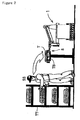
- Figure 3 is an explanatory view of a tank mounting step in the main line.
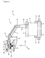
- Figure 4 is a structural drawing of the parts conveying/mounting device.
- Figure 5 is a block diagram of the parts conveying/mounting device.
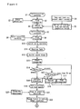
- Figure 6 to Figure 8 are flow charts showing operation contents in each of the steps of a parts conveying/mounting method.
- vehicle body (mounted body) W shown by a virtual line is made to flow in the direction of the thick arrow shown in the figure at a constant speed (for example 0.1m/s) in a state of being hung by a conveyor apparatus (not shown).
- a tank placing base (parts feeding section) TB and a tank storage rack TT are provided in the line side (lower side in Figure 1).
- a worker SS of a sub-step takes out a tank T from the tank storage rack TT, and transfers the tank onto the tank placing base TB to perform a small assembly operation.
- the worker SS of the sub-step confirms that the tank T is placed at a predetermined position on the placing base TB, goes out of the tank take-out area TA shown in Figure 1 to depress a completion switch (push-button switch) KB.
- a tank reception request instruction is fed to a self-traveling parts conveying/mounting device (power assist device) 1 via a host device and the like.
- a self-traveling parts conveying/mounting device power assist device 1
- tank take-out area entry detecting means SK consisting of a mat switch (floor switch) and a photoelectric area sensor and the like, which are provided in the tank take-out area
- the entry information is fed to the parts conveying/mounting device 1 via the host device and the like (or directly).
- the parts conveying/mounting device 1 suspends its operation.
- the parts conveying/mounting device 1 traveling toward a parts reception position TP reduces the travel speed and thereafter stops the traveling at a spot of a predetermined distance ahead of the parts reception position TP (a spot on the side of the main line ML from the tank take-out area TA).
- the parts conveying/mounting device 1 When receiving the tank T placed on the tank placing base TB by moving a tank support mechanism 8 upward (see Figure 2), the parts conveying/mounting device 1 travels along a travel guiding route K consisting of magnets laid on the floor to the main line ML at a high speed (for example 0.6 m/s), and thereafter temporarily stops at a stand-by position TP.
- a travel guiding route K consisting of magnets laid on the floor to the main line ML at a high speed (for example 0.6 m/s), and thereafter temporarily stops at a stand-by position TP.
- a vehicle body passage photoelectric sensor WS for detecting passage of a vehicle body W and a hanger synchronous encoder HE for detecting position of a hunger are provided for the main line as shown in Figure 5.
- Each of output signals of the vehicle body passage photoelectric sensor WS and the hanger synchronous encoder HE is fed to the parts conveying/mounting device 1.
- the parts conveying/mounting device 1 stands by at the standby position TP in a state where the travel direction is changed.
- the parts conveying/mounting device 1 travels synchronously with the flow of the vehicle body W on the basis of the output signal of the hanger synchronous encoder HE.
- the parts conveying/mounting device 1 recognizes a tank mounting position on the basis of vehicle type information (or tank mounting position information) fed via the host device 30, and automatically travels synchronously with the flow of the vehicle body W so as to maintain a predetermined positional relationship between the tank mounting position of the vehicle body W and the tank T.
- the parts conveying/mounting device 1 raises the support position of the tank T to make the tank T close to the mounting position of the vehicle body W and continues the synchronized travel while maintaining the positional state.
- a worker MS of the main line switches a mode change over switch of the parts conveying/mounting device 1 from the automatic side to the assist side. Then, as shown in Figure 3, the worker MS operates an operation lever 16 to make the tank in contact with the tank mounting position of the vehicle body W, while receiving power assist in moving the tank T, and thereafter releasing the hand from the operation lever. Even when the hand is released from the operation lever, the self-travelingpower assist device 1 maintains the position of the tank T, so that the worker MS of the main line mounts the tank T to the vehicle body W by using, for example, a metallic band and the like and fixes the tank T by tightening tank bolts via the metallic band and the like. The worker MS of the main line can use both hands, and hence, can efficiently perform the mounting operation of the tank T.
- the worker MS of the main line grasps the operation lever 16 to move the tank support mechanism 8 downward (to a region in which the tank T does not interfere with the vehicle body W). Then, the worker MS of the main line switches the mode changeover switch MS to the automatic side and thereafter depresses a completion switch KS. Noted that when the worker MS of the main line depresses the completion switch KS, the parts conveying/mounting device 1 may be arranged to automatically move the tank support mechanism 8 downward (to a region in which the tank T does not interfere with the vehicle body W). Thereby, the workload of the worker MS of the main line can be further reduced.
- the parts conveying/mounting device 1 stops low-speed synchronous travel, and travels in the return direction (the direction reverse to the flow direction of the vehicle body W) to temporarily stop at the stand-by position TP. Then, the parts conveying/mounting device 1 changes the travel direction and starts self-traveling at high speed to return to the parts reception position SP.
- the parts conveying/mounting device 1 repeats reception of the tank T, high-speed conveyance to the main line, low-speed synchronous travel in the main line, and return travel after mounting of the tank T.
- the tank T is automatically conveyed to the vicinity of the vehicle body W by the parts conveying/mounting device 1, so that the worker MS of the main line can efficiently perform mounting operation of the tank T only by positioning the tank T in the assist mode.
- FIG. 4 is a structural drawing of the parts conveying/mounting device according to the present invention.
- the parts conveying/mounting device 1 is constituted by providing a power assist mechanism 4 in the upper part of a self-traveling carrier body 3 provided with a plurality of traveling wheels 2, 2.
- the power assist mechanism 4 consists of an arm support base 6 vertically provided for a table 5 movable in two directions T, B orthogonal to each other, an arm 7 rotatably mounted to the arm support base 6, and the tank support mechanism 8 connected to the tip of the arm 7.
- the table 5 is moved in the T direction by a T direction drive motor 9.
- the table 5 is also moved in the B direction by a B direction drive motor 10.
- the arm 7 is rotated by an H direction drive motor 11.
- the tank support mechanism 8 comprises a vertical section 12 linked to the tip of the arm 7, a horizontal section 13 mounted to the vertical section 12, a tank support section 15 mounted to the horizontal section 13 via a floatingmechanism 14, and the operation lever 16 mounted to the vertical section 12 (or the horizontal section 13).
- a grip section (assist grip) 17 at the tip of the operation lever 16 is provided with a deadman switch 18 and an operation force sensor 19.
- the floating mechanism 14 holds the tank supporting section 15 movably in three axial directions (H, T, B).
- the floating mechanism 14 consists of a slide mechanism for three axial directions, floating springs 20, 21, 22 for each direction, and three displacement sensors (workpiece reaction force sensors) 23, 24, 25 for detecting the displacement in each axial direction (see Figure 5).
- a pair of bumper switches 26, 26 which operate at the time of contacting an obstacle or the like, and a pair of laser scanner sensors 27, 27 searching an obstacle or the like in a front part in the travel direction are provided, respectively.
- FIG. 5 is a block diagram of the parts conveying/mounting device according to the present invention.
- the parts conveying/mounting device 1 comprises a travel control section 31, an operation control section 32, an assist control section 33, an operation/display panel section 34, a motor drive section 35 and a power supply section 36.
- Reference numeral 37 denotes a movable cable, through which electric power, various kinds of signals and information are supplied. Noted that a battery may be mounted in the carrier body 3 so as to make transmission and reception of various signals and information wirelessly performed. In this case, the movable cable 37 becomes unnecessary.
- the present embodiment is configured so as to make serial data communication performed between the host device 30 and the parts conveying/mounting device 1. Then, vehicle kind information (vehicle type information and information about the tank mounting position) is arranged to be fed from the host device 30 to the parts conveying/mounting device 1, while depression information of the completion switch KB indicating that the preset operation of the tank in the line side is completed, and entry detection information of the tank take-out area entry detecting means SK are arranged to be fed to the host device 30. Further, the operation state of the parts conveying/mounting device 1, and abnormality information at the time of occurrence of abnormality are arranged to be fed from the parts conveying/mounting device 1 to the host device 30.
- vehicle kind information vehicle type information and information about the tank mounting position
- depression information of the completion switch KB indicating that the preset operation of the tank in the line side is completed
- entry detection information of the tank take-out area entry detecting means SK are arranged to be fed to the host device 30.
- the travel control section 31 is constituted by using a microcomputer system, and comprises a communication I/F (interface) section, a digital I/O (input output) section, an analog I/O (input output) section, encoder/counter section, motion control section and the like.
- travel guiding magnets MK which form the travel guiding route K are laid on the floor of the tank mounting process. Further, position scale magnets MS are laid along the travel guiding route K. Further, at the parts reception position SP and the temporary stop position TP, there are provided stop/junction point magnets MP which indicate these positions.
- a travel guiding magnetic sensor 41 For the bottom portion of the parts conveying/mounting device 1 (carrier body 3) , there are provided a travel guiding magnetic sensor 41, a position scale magnetic sensor 42 and a stop/junction point magnetic sensor 43 for detecting each of the magnets MK, MS, MP.
- the travel control section 31 recognizes the travel path K on the basis of detection outputs of the travel guiding magnetic sensor 41, and makes the carrier body 3 travel along the travel path K.
- the travel control section 31 recognizes the travel distance and the present position by counting detection outputs of the position scale magnetic sensors 42. Also, the travel control section 31 successively calculates the travel speed to control the rotation speed of each of the travel motors 44, 45 so that the rotation speedbecomes a target speed.
- the travel control section 31 drives a travel direction change motor 46 to change the travel direction.
- the travel control section 31 stops each of the travel motors 44, 45.
- the travel control section 31 reduces the travel speed in accordance with the distance to the obstacle or stops traveling.
- the operation control section 32 is constituted by utilizing a microcomputer system.
- the operation control section 32 respectively monitors the operation of the travel control section 31 and the assist control section 33, and also performs control of cooperation operation and sequence operation between the travel control section 31 and the assist control section 33.
- the operation control section 32 and the travel control section 31 may be constituted by a single microcomputer system.
- the operation control section 32, the travel control section 31 and the assist control section 33 may be constituted by a single microcomputer system.
- the assist control section 33 is constituted by utilizing a microcomputer system.
- the assist control section 33 adjusts the support position of the tank by controlling the rotation of each of the drive motors 9, 10, 11.
- the assist control section 33 controls the operation of each of the drive motors 9, 10, 11 on the basis of the detection output of the operation force sensor 19 to feed the assist force (perform power assist) when the tank is moved.
- the operation force sensor 19 uses sensors detecting the operation force in three axial directions (directions of T, B, H), respectively. Specifically, the operation force in each direction is arranged to be detected by using at least three pressure sensors and load cells.
- the assist control section 33 controls the work assist force (assist force) fed by each of the drive motors 9, 10, 11, corresponding to the operation force in each direction.
- the assist control section 33 monitors the output of each of the displacement sensors 23, 24, 25. When the displacement for example in the H direction is detected in the assist mode, the assist control section 33 reduces the assist force in the H direction corresponding to the displacement. Thereby, when the tank T contacts the vehicle body W, the reaction force can be given to the worker MS who operates the operation lever 16. The worker MS can sense that tank T touches the vehicle body W and the like, because the force to operate the operation lever 16 becomes heavy.
- the deadman switch 18 is a three position switch. When the switch lever is operated by a proper force, the deadman switch 18 is in the on (closed) state. When the switch lever is not operated and tightly grasped, the deadman switch 18 is in the off (open) state. Even if the mode changeover switch MS is set to the assist mode side, when a deadman switch 18 is in the off (open) state, the assist control section 33 stops feeding electric power to each of the drive motors 9, 10, 11, so as to stop feeding the work assist force (assist force).
- the operation/display panel section 34 comprises various kinds of operation switches (for example an emergency stop push-button switch, an abnormality reset push-button switch, an operation preparation switch, a switch for switching teaching mode, panel operation mode and remote control mode, and the like) in addition to the completion switch KS and the mode changeover switch MS.
- the operation/display panel section 34 also comprises various state indicators composed of lamps for indicating the operation state, a character display device and the like. The control state in the travel control section 31 is fed to the operation/display panel section 34 via the operation control section 32, so as to be displayed.
- the parts conveying/mounting device 1 comprises a connection connector 51 to be connected with a teaching pendant 50.
- the assist control section 33 comprises a communication function to communicate with the teaching pendant 50.
- the moving operation of the tank support mechanism 8 can be taught and set by using the teaching pendant 50.
- FIGS. 6 to Figure 8 are flow charts showing operation contents in each of the steps of a parts conveying/mounting method according to the present invention.
- the parts conveying/mounting device 1 is assumed to be self-traveling toward the parts reception position SP.
- the tank take-out area entry detecting means SK detects the entry of a person into the tank take-out area TA (step S2), the parts conveying/mounting device 1 stops traveling (step S3).
- the worker SS of the sub-step performs a small assembly operation for taking out the tank in the tank take-out area TA, and presets (mounts) the tank T on the tank placing base (parts feeding section) 8 (step S4).
- step S5 When worker SS goes out of the tank take-out area TA and depresses the completion switch KB (step S5), the parts conveying/mounting device 1 starts traveling (step S6). Thereby, the parts conveying/mounting device 1 is in the state of self-traveling on the return path (step S7).
- the parts conveying/mounting device 1 stops traveling (step S9).
- the parts conveying/mounting device 1 automatically operates an assist servo, and moves the arm 7 upwards (step S10) to move upward the tank support mechanism 8 which is in a lowered state. Thereby, the parts conveying/mounting device 1 receives the tank T preset (mounted) on the tank placing base (parts feeding section) 8 (step S11). When receiving the tank T, the parts conveying/mounting device 1 stops the assist servo (step S12), and starts traveling (step S13).
- the parts conveying/mounting device 1 irradiates a laser beam to the front part in the travel direction by means of the laser scanner sensor 27 while scanning the laser beam, thereby detecting an obstacle and measuring the distance to the obstacle on the basis of the light reflected by the obstacle.
- the distance to the obstacle is determined in step S15.
- the travel speed is reduced (step S16).
- the travel is stopped (step S17).
- the parts conveying/mounting device 1 When there is no obstacle, and when the obstacle is removed, the parts conveying/mounting device 1 continues to travel (step S18). Thereby, the parts conveying/mounting device 1 self-travels at high speed toward the main line ML along the travel guiding route K (step S19).
- the parts conveying/mounting device 1 stops traveling (step S21).
- the parts conveying/mounting device 1 in the state of temporary stop at the stand-by position TP, turns the wheels to change the travel direction to the conveyance direction of the vehicle body W (step S22).
- the parts conveying/mounting device 1 When passage of the vehicle body W is detected by the vehicle body passage photoelectric sensor WS (step S23), the parts conveying/mounting device 1 in the state of temporary stop at the stand-by position TP starts to travel synchronously with the vehicle body W (step S24).
- the parts conveying/mounting device 1 may automatically operate the assist servo tomove the arm7 further upward from the position at the time of conveying the tank (at the time of traveling) , so that the tank T is brought closer to the tank mounting portion of the vehicle body W. Thereby, the moving amount for positioning in mounting the tank can be reduced, so that the positioning operation canbe more easily performed.
- the main lineworkerMS switches the mode changeover switch MS of the parts conveying/mounting device 1 from the automatic side to the assistance side (step S25).
- the worker MS grasps the grip section 17 (assist grip) of the operation lever 16 to put the deadman switch 18 provided for the grip section 17 (assist grip) into the on-state (step S26)
- the assist servo using each of the drive motors 9, 10, 11 as the actuator is put into operation (step S27).
- the operating force with which the worker MS operates the grip section 17 (assist grip) of the operation lever 16 is detected by the operation force sensor 19, so that the assist force in the operation direction is fed by each of the drive motors 9, 10, 11.
- the worker MS can move the tank T placed on the tank support section 15 of the tank support mechanism 8 by light power.
- step S30 When the workerMS positions the tank T at the tankmounting portion of the vehicle body W (step S28), and releases the hand from the grip section 17 (assist grip) to put the deadman switch 18 into the off-state (step S29), the assist servo is stopped (step S30). Even when the assist servo is stopped, the tank T is held at the positioned position, so that the worker MS can perform the tank mounting operation such as tightening operation of tank bolts in a state where both hands are free (step S31). After mounting the tank T to the vehicle body W, the worker MS grasps the grip section 17 (assist grip) to put the deadman switch 18 into the on-state (step S32). Thereby, the assist servo operates (step S33), so that the worker MS can move in the state of receiving the power assist the tank support mechanism (jig) 8 to the position where the tank support mechanism does not interfere with the vehicle body W (step S34).
- step S35 After moving the tank support mechanism (jig) 8 to the position where the tank support mechanism does not interfere with the vehicle body W, the worker MS releases the hand from the grip section 17 (assist grip) (step S35). By releasing the hand from the grip section 17 (assist grip), the deadman switch 18 is put into the off-state, so that the assist servo is stopped (step S36).
- step S38 the worker MS switches the mode changeover switch MS from the assistance side to the automatic side.
- step S38 the completion switch KS
- step S39 the parts conveying/mounting device 1 stops low-speed synchronous travel (step S39) continued up to that time (step S40).
- the parts conveying/mounting device 1 When stopping the low-speed synchronous travel, the parts conveying/mounting device 1 starts self-traveling in the return direction in step S41.
- the parts conveying/mounting device 1 irradiates a laser beam to the front part in the return travel direction by the laser scanner sensor 27 for the return travel direction while scanning the laser beam, thereby detecting an obstacle and measuring the distance to the obstacle on the basis of the light reflected by the obstacle.
- the distance to the obstacle is determined in step S43.
- the travel speed is reduced (step S44).
- the distance to the obstacle is less than 50 cm, the travel is stopped (step S45).
- the parts conveying/mounting device 1 When there is no obstacle and when the obstacle is removed, the parts conveying/mounting device 1 continues to travel (step S46). Thereby, the parts conveying/mounting device 1 self-travels at high speed toward the stand-by position TP along the travel guiding route K (step S46).
- the parts conveying/mounting device 1 stops traveling at the stand-by position TP (step S48).
- the parts conveying/mounting device 1 in a state of temporary stop at the stand-by position TP, turns the wheels to change the travel direction to the direction toward the parts reception position SP (step S49).
- the parts conveying/mounting device 1 starts self-traveling in the return direction (step S50). Thereby, the parts conveying/mounting device 1 self-travels at high speed toward the parts reception position SP (step S51).
- the reaching of the parts stop position SP is detected by the stop/junction point magnetic sensor 43 (step S52)
- the parts conveying/mounting device 1 stops traveling (step S53).
Landscapes
- Engineering & Computer Science (AREA)
- Mechanical Engineering (AREA)
- Transportation (AREA)
- Robotics (AREA)
- Combustion & Propulsion (AREA)
- Chemical & Material Sciences (AREA)
- Manufacturing & Machinery (AREA)
- Structural Engineering (AREA)
- Civil Engineering (AREA)
- Life Sciences & Earth Sciences (AREA)
- Geology (AREA)
- Automatic Assembly (AREA)
- Automobile Manufacture Line, Endless Track Vehicle, Trailer (AREA)
- Control Of Position, Course, Altitude, Or Attitude Of Moving Bodies (AREA)
- Manipulator (AREA)
Applications Claiming Priority (2)
| Application Number | Priority Date | Filing Date | Title |
|---|---|---|---|
| JP2003192102A JP4350441B2 (ja) | 2003-07-04 | 2003-07-04 | 部品搬送・取付方法およびその装置 |
| PCT/JP2004/009170 WO2005002783A1 (ja) | 2003-07-04 | 2004-06-30 | 部品搬送・取付方法およびその装置 |
Publications (2)
| Publication Number | Publication Date |
|---|---|
| EP1642671A1 true EP1642671A1 (de) | 2006-04-05 |
| EP1642671A4 EP1642671A4 (de) | 2008-06-18 |
Family
ID=33562387
Family Applications (1)
| Application Number | Title | Priority Date | Filing Date |
|---|---|---|---|
| EP04746639A Withdrawn EP1642671A4 (de) | 2003-07-04 | 2004-06-30 | Teilebeförderungs- und -befestigungsverfahren und vorrichtung dafür |
Country Status (6)
| Country | Link |
|---|---|
| US (1) | US20090199385A1 (de) |
| EP (1) | EP1642671A4 (de) |
| JP (1) | JP4350441B2 (de) |
| CN (1) | CN100540209C (de) |
| CA (1) | CA2530869A1 (de) |
| WO (1) | WO2005002783A1 (de) |
Cited By (9)
| Publication number | Priority date | Publication date | Assignee | Title |
|---|---|---|---|---|
| WO2009106984A2 (en) * | 2008-02-27 | 2009-09-03 | Toyota Jidosha Kabushiki Kaisha | Power assist device and method of controlling the power assist device |
| FR2942156A3 (fr) * | 2009-02-19 | 2010-08-20 | Peugeot Citroen Automobiles Sa | Poste de montage d'un vehicule automobile comportant un robot muni d'un organe de prehension |
| WO2011088865A1 (de) * | 2010-01-21 | 2011-07-28 | Daimler Ag | Montageeinrichtung |
| WO2012119716A1 (de) * | 2011-03-09 | 2012-09-13 | Eisenmann Ag | Tauchbehandlungsanlage für fahrzeugkarosserien und verfahren zum betreiben einer solchen |
| WO2015049136A3 (de) * | 2013-09-26 | 2015-06-11 | Kuka Systems Gmbh | Arbeitsvorrichtung und arbeitsverfahren |
| ITUB20155597A1 (it) * | 2015-11-16 | 2017-05-16 | Fca Italy Spa | Attrezzature per linee di assemblaggio di autoveicoli |
| ITUB20155610A1 (it) * | 2015-11-16 | 2017-05-16 | Fca Italy Spa | Attrezzature per linee di assemblaggio di autoveicoli |
| ITUB20155595A1 (it) * | 2015-11-16 | 2017-05-16 | Fca Italy Spa | Attrezzature per linee di assemblaggio di autoveicoli |
| FR3073508A1 (fr) * | 2017-11-14 | 2019-05-17 | Renault S.A.S. | Ligne d'acheminement comprenant un chariot de transport ameliore |
Families Citing this family (25)
| Publication number | Priority date | Publication date | Assignee | Title |
|---|---|---|---|---|
| JP4553203B2 (ja) * | 2005-08-01 | 2010-09-29 | 国立大学法人 名古屋工業大学 | 作業補助装置 |
| JP2007038059A (ja) * | 2005-08-01 | 2007-02-15 | Nagoya Institute Of Technology | 作業補助装置 |
| CN101300105A (zh) * | 2005-09-05 | 2008-11-05 | 本田技研工业株式会社 | 装置和人的共同作业系统 |
| WO2007029306A1 (ja) * | 2005-09-05 | 2007-03-15 | Honda Motor Co., Ltd. | 搬送・組付けシステム |
| JP4562722B2 (ja) * | 2006-12-07 | 2010-10-13 | 本田技研工業株式会社 | 部品位置決め方法 |
| JP4221619B1 (ja) * | 2007-09-07 | 2009-02-12 | トヨタ自動車株式会社 | ワーク搭載装置 |
| JP4508263B2 (ja) * | 2008-04-24 | 2010-07-21 | トヨタ自動車株式会社 | パワーアシスト装置およびその制御方法 |
| CN104308849B (zh) * | 2009-05-22 | 2016-06-01 | 丰田自动车东日本株式会社 | 作业辅助机器人系统 |
| FR2956372B1 (fr) * | 2010-02-18 | 2015-03-20 | Peugeot Citroen Automobiles Sa | Ligne d'assemblage de caisses de vehicules automobiles ou d'applications sous caisses de vehicules automobiles equipee d'une fosse accessible par un operateur et procede mettant en oeuvre une telle ligne |
| CN102085611B (zh) * | 2010-11-11 | 2012-09-12 | 宁波工程学院 | 应变片自动装配方法及装配系统 |
| DE202013102095U1 (de) * | 2013-05-14 | 2014-08-18 | Hubtex Maschinenbau Gmbh & Co. Kg | Begleitversorgungsplattform |
| JP6336340B2 (ja) * | 2014-06-23 | 2018-06-06 | 住友ゴム工業株式会社 | ハンドリング装置および前記ハンドリング装置に用いるアタッチメント |
| WO2016129045A1 (ja) * | 2015-02-09 | 2016-08-18 | 株式会社日立製作所 | 搬送システム、搬送システムに用いられるコントローラ、および、搬送方法 |
| CN104708632B (zh) * | 2015-03-27 | 2017-03-22 | 河北工业大学 | 板材搬运安装机械手控制系统 |
| CN104972427B (zh) * | 2015-06-19 | 2017-01-11 | 北京新联铁科技股份有限公司 | 一种转向架牵引拉杆张拉器 |
| KR101724490B1 (ko) * | 2015-12-02 | 2017-04-07 | 기아자동차 주식회사 | 협업로봇을 이용한 차량 생산시스템 및 생산방법 |
| CN107914261A (zh) * | 2017-09-29 | 2018-04-17 | 中冶宝钢技术服务有限公司 | 放射源源罐拆装装置 |
| JP7047749B2 (ja) * | 2018-12-20 | 2022-04-05 | トヨタ自動車株式会社 | 自動車の製造方法 |
| CN110509043B (zh) * | 2019-09-03 | 2021-07-09 | 上海发那科机器人有限公司 | 一种机器人随动汽车主轮胎的安装拧紧系统及方法 |
| NL2025670B1 (en) * | 2020-05-26 | 2021-12-13 | Meyn Food Processing Tech Bv | A method for hanging poultry or parts thereof on an overhead conveyor, a system and an apparatus |
| JP2022025271A (ja) | 2020-07-29 | 2022-02-10 | セイコーエプソン株式会社 | 作業方法およびロボットシステム |
| JP7301409B2 (ja) * | 2021-01-08 | 2023-07-03 | 株式会社LexxPluss | 搬送システム、及び搬送制御方法 |
| WO2022149285A1 (ja) * | 2021-01-08 | 2022-07-14 | 株式会社LexxPluss | 搬送システム、及び搬送制御方法 |
| FR3129100A1 (fr) * | 2021-11-17 | 2023-05-19 | Psa Automobiles Sa (To Use) | Système manipulateur pour robot d’assistance intelligent |
| CN115432085B (zh) * | 2022-09-29 | 2023-07-21 | 深蓝汽车科技有限公司 | 一种避免汽车功能设计与产线生产冲突的方法 |
Citations (11)
| Publication number | Priority date | Publication date | Assignee | Title |
|---|---|---|---|---|
| JPS61100329A (ja) * | 1984-10-18 | 1986-05-19 | Mitsubishi Motors Corp | 作業用台車 |
| GB2168174A (en) * | 1984-11-05 | 1986-06-11 | Nissan Motor | Method and system for automatically attaching works onto vehicle bodies carried on a conveyor |
| JPS61244680A (ja) * | 1985-04-24 | 1986-10-30 | Honda Motor Co Ltd | 車体への重量ワ−ク取付装置 |
| US5088176A (en) * | 1990-03-16 | 1992-02-18 | Fuji Jukogyo Kabushiki Kaisha | Apparatus for aid in attaching work |
| JPH06119047A (ja) * | 1992-10-09 | 1994-04-28 | Daifuku Co Ltd | 搬送設備 |
| JPH06219349A (ja) * | 1993-01-27 | 1994-08-09 | Honda Motor Co Ltd | 燃料タンク組付装置 |
| EP0629469A1 (de) * | 1992-12-04 | 1994-12-21 | Toyota Jidosha Kabushiki Kaisha | Automatische montagevorrichtung |
| US6109424A (en) * | 1997-03-20 | 2000-08-29 | Fori Automation, Inc. | Chassis/body marriage lift machine |
| EP1110854A2 (de) * | 1999-12-23 | 2001-06-27 | Hyundai Motor Company | Robotersystem synchronisiert mit der Förderbandgeschwindigkeit und Bereitstellung von Fahrzeugsitzen mit so einem Robotersystem |
| JP2003072609A (ja) * | 2001-09-06 | 2003-03-12 | Daifuku Co Ltd | 自動車等の組立用搬送装置 |
| WO2005077591A1 (ja) * | 2004-02-12 | 2005-08-25 | Honda Motor Co., Ltd. | 部品位置決め方法及びその装置 |
Family Cites Families (36)
| Publication number | Priority date | Publication date | Assignee | Title |
|---|---|---|---|---|
| DE1704112C3 (de) * | 1968-01-09 | 1974-01-17 | Fa. Hermann Heye, 4962 Obernkirchen | Maschine zur Herstellung von Hohlkörpern nach dem Preß-Blas-Verfahren und Verfahren zu ihrer Steuerung und Regelung |
| US3839004A (en) * | 1968-01-09 | 1974-10-01 | Heye H | Process for the production of glass bottles or the like |
| JPS62168766A (ja) * | 1986-01-22 | 1987-07-25 | Mazda Motor Corp | 車体組立装置 |
| JPS584378A (ja) * | 1981-06-29 | 1983-01-11 | ファナック株式会社 | ワ−ク供給装置 |
| US4740133A (en) * | 1983-11-24 | 1988-04-26 | Mazda Motor Corporation | Composite working device using a robot and method of accomplishing composite work using a robot |
| US4611749A (en) * | 1983-11-28 | 1986-09-16 | Mazda Motor Corporation | Method of and system for assembling a plurality of parts into a unit |
| GB2168934B (en) * | 1984-12-19 | 1988-07-27 | Honda Motor Co Ltd | Method and apparatus for mounting parts to both sides of a main body |
| US4869416A (en) * | 1986-07-09 | 1989-09-26 | Mazda Motor Corporation | Assembly line conveyance |
| US4894908A (en) * | 1987-08-20 | 1990-01-23 | Gmf Robotics Corporation | Method for automated assembly of assemblies such as automotive assemblies and system utilizing same |
| US4815190A (en) * | 1987-08-20 | 1989-03-28 | Gmf Robotics Corporation | Method for automated assembly of assemblies such as automotive assemblies |
| JP2708434B2 (ja) * | 1987-10-08 | 1998-02-04 | マツダ株式会社 | 車体組付方法および装置 |
| JP2831999B2 (ja) * | 1987-12-01 | 1998-12-02 | マツダ株式会社 | 自動車組立ラインの足回り部組付装置 |
| DE68924999T2 (de) * | 1988-06-11 | 1996-04-25 | Nissan Motor | Verfahren zum Zusammenbau eines Fahrzeugaufbaus. |
| US5102280A (en) * | 1989-03-07 | 1992-04-07 | Ade Corporation | Robot prealigner |
| IT1248419B (it) * | 1990-06-15 | 1995-01-16 | Comau Spa | Stazione di assemblaggio di struttura di lamiera stampata provvista di robot di saldatura utilizzabili anche per il controllo periodico delle attrezzature utilizzate nella stazione. |
| JP2520787B2 (ja) * | 1990-11-28 | 1996-07-31 | 本田技研工業株式会社 | 車両のリヤフロア加工ライン |
| DE9105490U1 (de) * | 1991-05-03 | 1992-09-10 | Kuka Schweissanlagen + Roboter Gmbh, 8900 Augsburg, De | |
| US5191694A (en) * | 1991-07-03 | 1993-03-09 | Shape Inc. | Cassette assembly line |
| JP3189235B2 (ja) * | 1992-06-16 | 2001-07-16 | 株式会社アイジー技術研究所 | 目地構造 |
| US5226584A (en) * | 1992-10-27 | 1993-07-13 | Kurata Corporation | Parts assembling method |
| US5311659A (en) * | 1993-08-09 | 1994-05-17 | Chrysler Corporation | Apparatus for installing instrument panel assemblies in automotive vehicle bodies |
| JP2732787B2 (ja) * | 1993-09-28 | 1998-03-30 | 本田技研工業株式会社 | タイヤ取付装置 |
| US5560535A (en) * | 1995-03-30 | 1996-10-01 | Western Atlas, Inc. | Flexible body framing system |
| JPH08282998A (ja) * | 1995-04-14 | 1996-10-29 | Sanyo Mach Works Ltd | バランサ |
| US6151772A (en) * | 1997-11-21 | 2000-11-28 | Pigott; Patrick C. | Automated machinery for fabricating a wrought-iron fence |
| JP4253864B2 (ja) * | 1998-05-26 | 2009-04-15 | 日産自動車株式会社 | 自動車のダッシュモジュール搭載装置 |
| DE29813669U1 (de) * | 1998-07-31 | 1999-12-23 | Kuka Schweissanlagen Gmbh | Flexible Arbeitsstation |
| JP2000095324A (ja) * | 1998-09-24 | 2000-04-04 | Mazda Motor Corp | 移送装置及びその制御方法 |
| JP3442300B2 (ja) * | 1998-11-30 | 2003-09-02 | 本田技研工業株式会社 | 車体用ウインドガラスの取付け装置 |
| JP3678046B2 (ja) * | 1999-03-31 | 2005-08-03 | 三菱自動車工業株式会社 | インストルメントパネルアセンブリの組付装置 |
| DE29908094U1 (de) * | 1999-05-06 | 2000-10-05 | Cooper Power Tools Gmbh & Co | Transportsystem |
| JP4343404B2 (ja) * | 2000-06-12 | 2009-10-14 | 本田技研工業株式会社 | 自動車用フロアの多機種混合生産方法 |
| US6932263B2 (en) * | 2002-04-08 | 2005-08-23 | Progressive Tool & Industries Co. | Vehicle framing system for plurality of vehicle body styles |
| DE102005027986B4 (de) * | 2005-06-16 | 2008-06-05 | Thyssenkrupp Drauz Nothelfer Gmbh | Verfahren und Anlage zum Zusammenbauen von Bauteilen einer Fahrzeugkarosserie |
| EP1958897B1 (de) * | 2006-07-25 | 2009-12-09 | Honda Motor Co., Ltd. | Förderverfahren und Fördervorrichtung |
| US7677428B2 (en) * | 2006-11-20 | 2010-03-16 | Comau, Inc. | Motor vehicle body framing apparatus |
-
2003
- 2003-07-04 JP JP2003192102A patent/JP4350441B2/ja not_active Expired - Fee Related
-
2004
- 2004-06-30 CN CNB2004800188373A patent/CN100540209C/zh not_active Expired - Fee Related
- 2004-06-30 US US10/562,904 patent/US20090199385A1/en not_active Abandoned
- 2004-06-30 CA CA002530869A patent/CA2530869A1/en not_active Abandoned
- 2004-06-30 WO PCT/JP2004/009170 patent/WO2005002783A1/ja active Application Filing
- 2004-06-30 EP EP04746639A patent/EP1642671A4/de not_active Withdrawn
Patent Citations (11)
| Publication number | Priority date | Publication date | Assignee | Title |
|---|---|---|---|---|
| JPS61100329A (ja) * | 1984-10-18 | 1986-05-19 | Mitsubishi Motors Corp | 作業用台車 |
| GB2168174A (en) * | 1984-11-05 | 1986-06-11 | Nissan Motor | Method and system for automatically attaching works onto vehicle bodies carried on a conveyor |
| JPS61244680A (ja) * | 1985-04-24 | 1986-10-30 | Honda Motor Co Ltd | 車体への重量ワ−ク取付装置 |
| US5088176A (en) * | 1990-03-16 | 1992-02-18 | Fuji Jukogyo Kabushiki Kaisha | Apparatus for aid in attaching work |
| JPH06119047A (ja) * | 1992-10-09 | 1994-04-28 | Daifuku Co Ltd | 搬送設備 |
| EP0629469A1 (de) * | 1992-12-04 | 1994-12-21 | Toyota Jidosha Kabushiki Kaisha | Automatische montagevorrichtung |
| JPH06219349A (ja) * | 1993-01-27 | 1994-08-09 | Honda Motor Co Ltd | 燃料タンク組付装置 |
| US6109424A (en) * | 1997-03-20 | 2000-08-29 | Fori Automation, Inc. | Chassis/body marriage lift machine |
| EP1110854A2 (de) * | 1999-12-23 | 2001-06-27 | Hyundai Motor Company | Robotersystem synchronisiert mit der Förderbandgeschwindigkeit und Bereitstellung von Fahrzeugsitzen mit so einem Robotersystem |
| JP2003072609A (ja) * | 2001-09-06 | 2003-03-12 | Daifuku Co Ltd | 自動車等の組立用搬送装置 |
| WO2005077591A1 (ja) * | 2004-02-12 | 2005-08-25 | Honda Motor Co., Ltd. | 部品位置決め方法及びその装置 |
Non-Patent Citations (1)
| Title |
|---|
| See also references of WO2005002783A1 * |
Cited By (12)
| Publication number | Priority date | Publication date | Assignee | Title |
|---|---|---|---|---|
| WO2009106984A2 (en) * | 2008-02-27 | 2009-09-03 | Toyota Jidosha Kabushiki Kaisha | Power assist device and method of controlling the power assist device |
| WO2009106984A3 (en) * | 2008-02-27 | 2009-12-10 | Toyota Jidosha Kabushiki Kaisha | Power assist device and method of controlling the power assist device |
| US20110010012A1 (en) * | 2008-02-27 | 2011-01-13 | Toyota Jidosha Kabushiki Kaisha | Power assist device and method of controlling the power assist device |
| US8392024B2 (en) | 2008-02-27 | 2013-03-05 | Toyota Jidosha Kabushiki Kaisha | Power assist device and method of controlling the power assist device |
| FR2942156A3 (fr) * | 2009-02-19 | 2010-08-20 | Peugeot Citroen Automobiles Sa | Poste de montage d'un vehicule automobile comportant un robot muni d'un organe de prehension |
| WO2011088865A1 (de) * | 2010-01-21 | 2011-07-28 | Daimler Ag | Montageeinrichtung |
| WO2012119716A1 (de) * | 2011-03-09 | 2012-09-13 | Eisenmann Ag | Tauchbehandlungsanlage für fahrzeugkarosserien und verfahren zum betreiben einer solchen |
| WO2015049136A3 (de) * | 2013-09-26 | 2015-06-11 | Kuka Systems Gmbh | Arbeitsvorrichtung und arbeitsverfahren |
| ITUB20155597A1 (it) * | 2015-11-16 | 2017-05-16 | Fca Italy Spa | Attrezzature per linee di assemblaggio di autoveicoli |
| ITUB20155610A1 (it) * | 2015-11-16 | 2017-05-16 | Fca Italy Spa | Attrezzature per linee di assemblaggio di autoveicoli |
| ITUB20155595A1 (it) * | 2015-11-16 | 2017-05-16 | Fca Italy Spa | Attrezzature per linee di assemblaggio di autoveicoli |
| FR3073508A1 (fr) * | 2017-11-14 | 2019-05-17 | Renault S.A.S. | Ligne d'acheminement comprenant un chariot de transport ameliore |
Also Published As
| Publication number | Publication date |
|---|---|
| CN1819893A (zh) | 2006-08-16 |
| US20090199385A1 (en) | 2009-08-13 |
| CN100540209C (zh) | 2009-09-16 |
| WO2005002783A1 (ja) | 2005-01-13 |
| JP4350441B2 (ja) | 2009-10-21 |
| CA2530869A1 (en) | 2005-01-13 |
| JP2005022050A (ja) | 2005-01-27 |
| EP1642671A4 (de) | 2008-06-18 |
Similar Documents
| Publication | Publication Date | Title |
|---|---|---|
| EP1642671A1 (de) | Teilebeförderungs- und -befestigungsverfahren und vorrichtung dafür | |
| CN108161889B (zh) | 一种基于agv的工业机器人 | |
| CN103286782B (zh) | 一种机器人的柔性跟踪定位系统及跟踪定位方法 | |
| JP5738149B2 (ja) | 薄板の加工のための機械式の加工装置、並びに該加工装置における工具交換のための方法 | |
| JP6249292B2 (ja) | 作業システム | |
| KR100743906B1 (ko) | 비용접부 최소화 오토캐리지 및 그의 용접방법 | |
| JPH0626205A (ja) | フロアパネル着脱装置およびフロアパネル | |
| JP4274865B2 (ja) | アシストエリアの設定方法 | |
| CN109048065B (zh) | 一种汽车前后轴自动化加工系统 | |
| CN111993568B (zh) | 安装设备及具有其的生产线 | |
| CN215478216U (zh) | 一种基于3d视觉定位下重卡桥壳类零件的智能搬运装置 | |
| CN210824060U (zh) | 往复式电机上料装置 | |
| JP2009148787A (ja) | 板材搬出設備 | |
| CN217731797U (zh) | 一种传送定位装置 | |
| JP2924990B2 (ja) | 物品搬送設備 | |
| CN210593913U (zh) | 具有轨道切换机构的中药饮片自动配药输送装置 | |
| CN115593537B (zh) | 一种多车型混流全景天窗装配系统 | |
| CN220885940U (zh) | 骨架错位分料定位机构 | |
| CN117532644B (zh) | 一种三维视觉引导机械手抓取装置及其控制方法 | |
| CN219881536U (zh) | 一种焊接设备 | |
| CN117517314B (zh) | 视觉检测设备 | |
| JP2001347943A (ja) | 組立ライン、部品用の搬送車、および自走搬送車の制御方法 | |
| CN108792600B (zh) | 一种用于上料系统的摆料装置 | |
| JPH0737824Y2 (ja) | ロボツトのコンベア同期装置 | |
| JP2824277B2 (ja) | 切断処理装置 |
Legal Events
| Date | Code | Title | Description |
|---|---|---|---|
| PUAI | Public reference made under article 153(3) epc to a published international application that has entered the european phase |
Free format text: ORIGINAL CODE: 0009012 |
|
| 17P | Request for examination filed |
Effective date: 20060103 |
|
| AK | Designated contracting states |
Kind code of ref document: A1 Designated state(s): DE GB |
|
| DAX | Request for extension of the european patent (deleted) | ||
| RBV | Designated contracting states (corrected) |
Designated state(s): DE GB |
|
| RIN1 | Information on inventor provided before grant (corrected) |
Inventor name: OZAWA, TETSUYAC/O HONDA ENGINEERING CO., LTD. Inventor name: OSADA, ATSUSHIC/O HONDA ENGINEERING CO., LTD. Inventor name: KATAMINE, TAKESHIC/O HONDA ENGINEERING CO., LTD. Inventor name: MARUO, MASARUC/O HONDA ENGINEERING CO., LTD. |
|
| A4 | Supplementary search report drawn up and despatched |
Effective date: 20080520 |
|
| RIC1 | Information provided on ipc code assigned before grant |
Ipc: B62D 65/18 20060101ALI20080514BHEP Ipc: B62D 65/02 20060101ALI20080514BHEP Ipc: B25J 13/00 20060101ALI20080514BHEP Ipc: G05B 19/418 20060101ALI20080514BHEP Ipc: B23P 19/00 20060101AFI20050114BHEP Ipc: B23P 21/00 20060101ALI20080514BHEP |
|
| 17Q | First examination report despatched |
Effective date: 20080725 |
|
| STAA | Information on the status of an ep patent application or granted ep patent |
Free format text: STATUS: THE APPLICATION IS DEEMED TO BE WITHDRAWN |
|
| 18D | Application deemed to be withdrawn |
Effective date: 20120920 |