EP1617061A1 - Lehrlaufdrehzahlregler für verbrennungsmotor, verbrennungsmotorsteuerung und verbrennungsmotor - Google Patents
Lehrlaufdrehzahlregler für verbrennungsmotor, verbrennungsmotorsteuerung und verbrennungsmotor Download PDFInfo
- Publication number
- EP1617061A1 EP1617061A1 EP04724133A EP04724133A EP1617061A1 EP 1617061 A1 EP1617061 A1 EP 1617061A1 EP 04724133 A EP04724133 A EP 04724133A EP 04724133 A EP04724133 A EP 04724133A EP 1617061 A1 EP1617061 A1 EP 1617061A1
- Authority
- EP
- European Patent Office
- Prior art keywords
- intake
- internal combustion
- combustion engine
- control valve
- rotational speed
- Prior art date
- Legal status (The legal status is an assumption and is not a legal conclusion. Google has not performed a legal analysis and makes no representation as to the accuracy of the status listed.)
- Granted
Links
- 238000002485 combustion reaction Methods 0.000 title claims abstract description 164
- 239000000446 fuel Substances 0.000 claims abstract description 83
- 238000011144 upstream manufacturing Methods 0.000 claims abstract description 12
- 238000002347 injection Methods 0.000 claims description 15
- 239000007924 injection Substances 0.000 claims description 15
- 238000010586 diagram Methods 0.000 description 16
- 230000000694 effects Effects 0.000 description 11
- 230000001360 synchronised effect Effects 0.000 description 5
- 230000006835 compression Effects 0.000 description 4
- 238000007906 compression Methods 0.000 description 4
- 238000013507 mapping Methods 0.000 description 4
- 230000000452 restraining effect Effects 0.000 description 4
- 238000001514 detection method Methods 0.000 description 3
- 230000002238 attenuated effect Effects 0.000 description 1
- 238000006243 chemical reaction Methods 0.000 description 1
Images


Classifications
-
- F—MECHANICAL ENGINEERING; LIGHTING; HEATING; WEAPONS; BLASTING
- F02—COMBUSTION ENGINES; HOT-GAS OR COMBUSTION-PRODUCT ENGINE PLANTS
- F02D—CONTROLLING COMBUSTION ENGINES
- F02D41/00—Electrical control of supply of combustible mixture or its constituents
- F02D41/02—Circuit arrangements for generating control signals
- F02D41/14—Introducing closed-loop corrections
- F02D41/16—Introducing closed-loop corrections for idling
-
- F—MECHANICAL ENGINEERING; LIGHTING; HEATING; WEAPONS; BLASTING
- F02—COMBUSTION ENGINES; HOT-GAS OR COMBUSTION-PRODUCT ENGINE PLANTS
- F02D—CONTROLLING COMBUSTION ENGINES
- F02D31/00—Use of speed-sensing governors to control combustion engines, not otherwise provided for
- F02D31/001—Electric control of rotation speed
- F02D31/002—Electric control of rotation speed controlling air supply
- F02D31/003—Electric control of rotation speed controlling air supply for idle speed control
- F02D31/005—Electric control of rotation speed controlling air supply for idle speed control by controlling a throttle by-pass
-
- F—MECHANICAL ENGINEERING; LIGHTING; HEATING; WEAPONS; BLASTING
- F02—COMBUSTION ENGINES; HOT-GAS OR COMBUSTION-PRODUCT ENGINE PLANTS
- F02D—CONTROLLING COMBUSTION ENGINES
- F02D41/00—Electrical control of supply of combustible mixture or its constituents
- F02D41/02—Circuit arrangements for generating control signals
- F02D41/04—Introducing corrections for particular operating conditions
- F02D41/08—Introducing corrections for particular operating conditions for idling
-
- F—MECHANICAL ENGINEERING; LIGHTING; HEATING; WEAPONS; BLASTING
- F02—COMBUSTION ENGINES; HOT-GAS OR COMBUSTION-PRODUCT ENGINE PLANTS
- F02D—CONTROLLING COMBUSTION ENGINES
- F02D2200/00—Input parameters for engine control
- F02D2200/02—Input parameters for engine control the parameters being related to the engine
- F02D2200/04—Engine intake system parameters
- F02D2200/0406—Intake manifold pressure
Definitions
- the present invention relates to an idle rotational speed controller, a controller of an internal combustion engine and an internal combustion engine, which enable stable idling operation.
- an internal combustion engine mounted to a vehicle including an auxiliary intake path opened to a downstream side of a throttle valve of an intake path and communicating with the atmosphere, a control valve for controlling an auxiliary air amount (idling intake amount) supplied to the internal combustion engine via the auxiliary intake path, and a fuel supplying unit for supplying a predetermined fuel amount in accordance with a total intake amount including the auxiliary air amount to a combustion chamber of the internal combustion engine, in which a predetermined rotational position of the internal combustion engine is detected and the control valve is opened in synchronism with a signal of the predetermined position (refer to, for example, Patent Reference 1).
- Patent Reference 1 JP-B-63-60219 (pagesl-7, Figs.1-4)
- a controller of an internal combustion engine for controlling a fuel supply amount of the fuel supplying unit by detecting an intake pressure of the intake path by an intake pressure detecting unit arranged on the downstream side of the throttle valve of the intake path, when the auxiliary intake path is connected to the downstream side of the throttle valve of the intake path and the control valve of an opening/closing type is used, there is a case in which by a change in the intake pressure by operating to open and close the control valve, despite a steady state, the state is erroneously determined to shift to an accelerating or decelerating state and an idling rotational speed becomes unstable.
- the invention has been carried out in view of such a situation and it is an object thereof to provide an idle rotational speed controller, a controller of an internal combustion engine and an internal combustion engine, which enable stable idling operation.
- the invention is constituted as follows.
- a first aspect of the invention is an idle rotational speed controller of an internal combustion engine including an intake path for sucking air to be supplied to a combustion chamber of the internal combustion engine, a throttle valve arranged at the intake path for controlling an intake amount, an auxiliary intake path for communicating the intake path on an upstream side of the throttle valve and the intake path on a downstream side of the throttle valve, and an opening/closing type control valve arranged at the auxiliary intake path for controlling an idling intake amount, the idle rotational speed controller including: an intake pressure detecting unit for detecting an intake pressure of the intake path; a fuel supplying unit for controlling a supply amount of a fuel supplied to the combustion chamber based on at least the intake pressure; and a controlling unit for synchronizing a drive reference position for driving to open or close the control valve with a timing of detecting the intake pressure by the intake pressure detecting unit.
- the controlling unit determines the fuel supply amount of the fuel supplying unit by predicting a steady state load from the intake pressure, for example, the intake pressure at a predetermined position of a crank angle of the internal combustion engine. Further, the fuel supply amount determined by the controlling unit is the fuel supply amount of a successive cycle.
- the intake pressure detecting unit by synchronizing the drive reference position of driving to open and close the control valve with the timing for detecting the intake pressure by the intake pressure detecting unit, it can be prevented that the intake pressure detecting unit erroneously detects a pressure fluctuation caused by operating to open and close the control valve and the supply amount of the fuel cannot stably be controlled, and stable idling rotation can be carried out.
- a second aspect of the invention is characterized in that the controlling unit controls a state of closing the control valve by setting a timing of driving to close the control valve as the drive reference position in the idle rotational speed controller of an internal combustion described in the first aspect.
- the control valve when an idling rotational speed is increased, the control valve is controlled in a direction of restraining an engine rotational speed, and when the idling rotational speed is reduced, the control valve is controlled in a direction of increasing the engine rotational speed, and therefore, the fluctuation in rotationof the internal combustion engine can be restrained.
- a third aspect of the invention is characterized in that the controlling unit increases the supply amount of the fuel when a pressure difference between the intake pressure before one cycle or more and a current one is equal to or larger than a threshold in accordance with a state of opening or closing the control valve in the idle rotational speed controller of an internal combustion engine described in the first aspect.
- the controlling unit detects an accelerating state by comparing, for example, the intake pressure before one cycle or more and the current intake pressure. Further, a state of opening or closing the control valve can be predicted or detected by, for example, an engine rotational speed, a throttle opening degree, a ratio (duty) of a time period of opening the control valve in a predetermined time period or the like.
- the third aspect of the invention in addition to the effect of the first aspect, it can be prevented that even when the state is a steady state, the state is erroneously determined to shift to the accelerating state by a change in the intake pressure caused by operating to open or close the control valve and the supply amount of the fuel is increased, and the fuel can stably be supplied.
- a fourth aspect of the invention is characterized in that the threshold is set by a two-dimensional table constituting an axis thereof by an engine rotational speed in the idle rotational speed controller of an internal combustion engine described in the third aspect.
- the threshold is set by the two-dimensional table constituting the axis thereof by the engine rotational speed, and therefore, the fuel can stably be supplied even at a low idling rotational speed at which the fluctuation in the intake pressure caused by operating to open or close the control valve is large.
- the idling rotational speed can stably be controlled without being erroneously determined that the state is not the steady state.
- a fifth aspect of the invention is characterized in that the controlling unit increases the supply amount of the fuel by asynchronous injection in the idle rotational speed controller of an internal combustion engine described in the third aspect.
- the fuel supply amount is increased by the asynchronous injection, and therefore, the fuel can be supplied swiftly and stably.
- a sixth aspect of the invention is an idle rotational speed controller of an internal combustion engine including an intake path for sucking air to be supplied to a combustion chamber of the internal combustion engine, a throttle valve arranged at the intake path for controlling an intake amount, an auxiliary intake path for communicating the intake path on an upstream side of the throttle valve and the intake path on a downstream side of the throttle valve, and an opening/closing type control valve arranged at the auxiliary intake path for controlling an idling intake amount, the idle rotational speed controller including: an intake pressure detecting unit for detecting an intake pressure of the intake path; a stroke determining unit for determining a stroke of the internal combustion engine based on at least the intake pressure; and a controlling unit for synchronizing a drive reference position for driving to open or close the control valve with a timing of detecting the intake pressure by the intake pressure detecting unit.
- the controlling unit determines the stroke of the internal combustion engine by, for example, a pressure difference of the intake pressure at a predetermined crank angle and a change in a speed of rotating a crank.
- the intake pressure detecting unit by synchronizing the drive reference position of driving to open or close the control valve with the timing of detecting the intake pressure by the intake pressure detecting unit, it can be prevented that the intake pressure detecting unit erroneously detects the fluctuation in the pressure caused by operating to open and close the control valve and the stroke cannot be determined, and stable idling rotation can be carried out.
- the control valve when the idling rotational speed is increased, the control valve is controlled in a direction of restraining the engine rotational speed, and when the idling rotational speed is reduced, the control valve is controlled in a direction of increasing the engine rotational speed, and therefore, the fluctuation in rotation of the internal combustion engine can be restrained.
- An eighth aspect of the invention is an idle rotational speed controller of an internal combustion engine including an intake path for sucking air to be supplied to a combustion chamber of the internal combustion engine, a throttle valve arranged at the intake path for controlling an intake amount, an auxiliary intake path for communicating the intake path on an upstream side of the throttle valve and the intake path on a downstream side of the throttle valve, and an opening/closing type control valve arranged at the auxiliary intake path for controlling an idling intake amount, the idle rotational speed controller including: an intake pressure detecting unit for detecting an intake pressure of the intake path; a stroke determining unit for determining a stroke of the internal combustion engine based on at least the intake pressure; and a controlling unit for controlling the control valve by synchronizing a drive reference position for driving to open or close the control valve with a timing of detecting the intake pressure by the intake pressure detecting unit, and changing the drive reference position with respect to a crank rotation of the internal combustion engine after finishing to determine the stroke by the stroke determining unit from that of before finishing to determine the stroke.
- the stroke of the internal combustion engine is determined based on the intake pressure of the intake path, and therefore, even in a state in which the stroke of the internal combustion engine cannot be determined immediately after starting the internal combustion engine, the intake amount sucked to the combustion chamber can be controlled by synchronizing the drive reference position without deviating the intake timing, and excellent engine starting performance and stable idling rotational speed control can be realized.
- a ninth aspect of the invention is characterized in that the controlling unit controls to bring about the drive reference position once for each rotation of a crank before finishing to determine the stroke by the stroke determining unit and bring about the drive reference position once for each two rotations of the crank after finishing to determine the stroke in the idle rotational speed controller of an internal combustion engine described in the eighth aspect.
- an effect as a fast idle device is further promoted and excellent engine starting performance and stable idling rotational speed control can be realized.
- a tenth aspect of the invention is an idle rotational speed controller of an internal combustion engine including an intake path for sucking air to be supplied to a combustion chamber of the internal combustion engine, a throttle valve arranged at the intake path for controlling an intake amount, an auxiliary intake path for communicating the intake path on an upstream side of the throttle valve and the intake path on a downstream side of the throttle valve, and an opening/closing type control valve arranged at the auxiliary intake path for controlling an idling intake amount
- the idle rotational speed controller including: an intake pressure detecting unit for detecting an intake pressure of the intake path; a stroke determining unit for determining a stroke of the internal combustion engine based on at least the intake pressure; and a controlling unit for controlling the control valve by synchronizing a drive reference position for driving to open or close the control valve with a timing of detecting the intake pressure by the intake pressure detecting unit, and preventing the control valve from being driven to open or close before finishing to determine the stroke by the stroke determining unit.
- the intake pressure detecting unit in a state inwhichthe stroke of the internal combustion engine immediately after starting the internal combustion engine is difficult to determine since the stroke of the internal combustion engine is determined based on the intake pressure of the intake path, by not driving to open or close the control valve, it can be prevented that the intake pressure detecting unit cannot determine the stroke by erroneously detecting the fluctuation in the pressure caused by operating to open or close the control valve, and excellent engine starting performance and stable idling rotational speed control can be realized.
- An eleventh aspect of the invention is an idle rotational speed controller of an internal combustion engine including an intake path for sucking air to be supplied to a combustion chamber of the internal combustion engine, a throttle valve arranged at the intake path for controlling an intake amount, an auxiliary intake path for communicating the intake path on an upstream side of the throttle valve and the intake path on a downstream side of the throttle valve, and an opening/closing type control valve arranged at the auxiliary intake path for controlling an idling intake amount, the idle rotational speed controller including: an intake pressure detecting unit for detecting an intake pressure of the intake path; a fuel supplying unit for controlling a supply amount of a fuel supplied to the combustion chamber based on at least the intake pressure; and a controlling unit for synchronizing a drive reference position for driving to open or close the control valve with a timing of detecting the intake pressure by the intake pressure detecting unit.
- the intake pressure detecting unit by synchronizing the drive reference position of driving to open or close the control valve with the timing of detecting the intake pressure by the intake pressure detecting unit, it can be prevented that the intake pressure detecting unit erroneously detects the fluctuation in the pressure caused by operating to open or close the control valve and the supply amount of the fuel cannot stably be controlled or the stroke cannot be determined, and stable idling rotation can be carried out.
- the control valve when the idling rotational speed is increased, the control valve is controlled in a direction of restraining the engine rotational speed, and when the idling rotational speed is reduced, the control valve is controlled in a direction of increasing the engine rotational speed, and therefore, the fluctuation in rotationof the internal combustion engine can be restrained.
- a thirteenth aspect of the invention is an internal combustion engine including the idle rotational speed controller of an internal combustion engine according to any one of the first to twelfth aspects of the invention.
- an internal combustion engine the rotational fluctuation of which is restrained and which is provided with the stable idle rotational speed controller having excellent engine starting performance.
- a fourteenth aspect of the invention is a controller of an internal combustion engine including an intake path for sucking air to be supplied to a combustion chamber of the internal combustion engine, a fuel supplying unit for supplying a fuel to the combustion chamber, a throttle valve arranged at the intake path for controlling an intake amount, and intake pressure detecting unit for detecting an intake pressure of the intake path; wherein the fuel supplying unit increases a supply amount of the fuel when a pressure difference of the intake pressure before one cycle or more and a current one is equal to or larger than a threshold in accordance with an engine rotational speed of the internal combustion engine.
- the fourteenth aspect of the invention it can be prevented that despite a steady state, the state is erroneously determined to shift to accelerating state and the fuel supply amount is increased, and the fuel can be supplied stably.
- a fifteenth aspect of the invention is characterized in that the threshold is set by a two-dimensional table constituting an axis thereof by an engine rotational speed in the internal combustion engine control apparatus described in the fourteenth aspect.
- the threshold is set by the two-dimensional table constituting the axis thereof by the engine rotational speed, and therefore, the fuel can stably be supplied without increasing the fuel supply amount erroneously by a low idling rotational speed at which the fluctuation in rotation is large.
- a sixteenth aspect of the invention is characterized in that the controlling unit increases the supply amount of the fuel by asynchronous injection in the internal combustion engine control apparatus described in the fourteenth aspect.
- the supply amount of the fuel is increased by the asynchronous injection, and therefore, the fuel can be supplied swiftly and stably.
- a seventeenth aspect of the invention is an internal combustion engine including the controller of an internal combustion engine according to any one of the fourteenth to sixteenth aspects.
- an internal combustion engine the rotational fluctuation of which is restrained and which includes the controller of the internal combustion engine having excellent engine starting performance and carrying out stable idling rotational speed control.
- numeral 1 designates an internal combustion engine
- numeral 2 designates a crank
- numeral 8 designates an intake path
- numeral 11 designates a throttle valve
- numeral 12 designates an auxiliary intake path
- numeral 13 designates a control valve
- numeral 15 designates controlling unit
- numeral 17 designates a fuel supplying unit
- numeral 30 designates crank angle detecting unit
- numeral 31 designates engine rotational speed detecting unit
- numeral 33 designates stroke determining unit
- notation S1 designates an intake pressure detecting unit
- notation S2 designates an engine temperature detecting unit
- notation S3 designates a crank pulse output detecting unit
- numeral 50 designates a control apparatus unit.
- Fig.1 is a constitution view substantially showing the whole of an idle rotational speed controller of an internal combustion engine
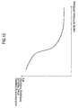
- Fig.2 is a diagram showing a relationship between a crank angle and an intake pressure
- Fig. 3 is a diagram showing a relationship between the crank angle and the intake pressure when a throttle opening degree is changed
- Fig.4 is a diagram showing a state of driving to open and close a control valve
- Fig.5 is a diagram showing a crank pulse and a stroke
- Fig.6 is a diagram showing the crank pulse, determination of the stroke, detection of the intake pressure, and a state of driving the control valve.
- the embodiment is applicable also to an internal combustion engine of multi cylinders.
- the crank 2 is connected to a piston 4 via a connecting rod 3, and the crank is rotated in an arrow mark direction by reciprocating the piton 4.
- the internal combustion engine 1 is provided with an ignition plug 6 that faces to a combustion chamber 5, and the combustion chamber 5 is opened with an exhaust path 7 and the intake path 8.
- An opening of the exhaust path 7 is opened and closed by an exhaust valve 9, an opening of the intake path 8 is opened and closed by an intake valve 10, and the exhaust valve 9 and the intake valve 10 are opened and closed in synchronism with rotation of the crank 2.
- the throttle valve 11 is arranged at a middle of the intake path 8 and the throttle valve 11 controls an intake amount for sucking air to be supplied to the combustion chamber 5.
- the intake path 8 is provided with the auxiliary intake path 12 for communicating an upstream side and a downstream side by bypassing the throttle valve 11, and the auxiliary intake path 12 is provided with the control valve 13 of an opening/closing type for controlling an idling intake amount.
- the intake pressure immediately after opening the intake valve 10 is high.
- the intake pressure is reduced and when the intake valve 10 is closed, the intake pressure is increased.
- a crank number of "0" designates a compression upper dead center.
- the intake pressure is changed by a throttle opening degree. That is, as the throttle opening degree is increased, a reduction in the intake pressure when the intake valve 10 is opened is reduced.
- the crank angle of "0" designates the compression upper dead center.
- the control valve 13 of the embodiment is constituted by a solenoid valve and opens/closes the auxiliary intake path 12 by being controlled by a controlling unit 15 provided at a control apparatus unit 50.
- the controlling unit 15 is constituted by CPU, RAM, ROM and the like.
- a drive reference position is constituted by a timing of driving to close the control valve 13 and by controlling a time period of closing the control valve 13, a ratio of a time period of opening the control valve 13 within a predetermined time period is controlled (duty control) to thereby drive to open and close the control valve 13.
- an idle intake amount is controlled by setting the drive reference position and the time period of closing the control valve.
- the intake path 8 is provided with a fuel injection valve 16 on a downstream side of a portion of communicating the throttle valve 11 and the auxiliary intake path 12.
- the fuel injection valve 16 constitutes fuel supplying unit along with the fuel pump 17 and the like and a fuel injection amount is controlled by the controlling unit 15 electrically connected thereto.
- the intake path 8 is provided with an intake pressure detecting unit S1 on the downstream side of the portion of communicating the throttle valve 11 and the auxiliary intake path 12.
- the intake pressure detecting unit S1 detects the intake pressure of the intake path 8 on the downstream side of the auxiliary intake path 12 and transmits information of the detected intake pressure to the controlling unit 15.
- the controlling unit 15 predicts a steady state load by the intake pressure at a predetermined position of a crank angle of the internal combustion engine 1 and determines a fuel supply amount of the fuel supplying unit, and therefore, the fuel can be supplied with high accuracy based on the intake pressure.
- the fuel supply amount determined by the controlling unit 15 is a fuel supply amount for a next cycle.
- the fuel can be supplied with high accuracy by making the intake path 8 and the auxiliary intake path 12 merge to communicate with the single combustion chamber 5 of the internal combustion engine 1.
- the fuel can be supplied with high accuracy based on the intake pressure by arranging the intake pressure detecting unit S1 on a downstream side of a merging portion 8a at which the intake path 8 and the auxiliary intake path 12 merge and detecting the intake pressure.
- the internal combustion engine 1 is provided with an engine temperature detecting unit S2.
- the engine temperature detecting unit S2 detects an engine temperature and transmits information of the detected engine temperature to the controlling unit 15.
- the internal combustion engine 1 is provided with a crank pulse outputting unit S3.
- the crank pulse outputting unit S3 outputs a crank pulse produced by a projection 2a of the rotating crank 2 and transmits the crank pulse to the controlling unit 15.
- control apparatus unit 50 is provided with a crank angle detecting unit 30, an engine rotational speed detecting unit 31, a stroke determining unit 33 and the like other than the controlling unit 15.
- the crank angle detecting unit 30 detects a crank angle of the crank 2 by the crank pulse produced by the crank pulse outputting unit S3.
- the engine rotational speed detecting unit 31 detects an engine rotational speed by the crank pulse produced by the crank pulse outputting unit S3.
- the controlling unit 15 controls the fuel supply amount by driving the fuel injection valve 16 and the fuel pump 17 in the fuel supplying unit based on the intake pressure and the engine rotational speed.
- crank pulse number is attached to a crank pulse produced by the projection 2a.
- a crank pulse number at a compression dead center is designated by "0". It is determined that the crank pulse numbers of "0" through “6” designate an expansion stroke, the crank pulse numbers of "6" through “12” designate an exhaust stroke, the crank pulse numbers of "12” through “18” designate an intake stroke, and the crank pulse numbers of "18" through “0” designate a compression stroke.
- cranking when cranking is stated by starting the internal combustion engine 1, the crank pulse is outputted, and the intake pressure is increased.
- the intake pressure is reduced when the crank pulse is not outputted, and the upper dead center is finished to be determined by a timing at which the crank pulse is not outputted.
- the intake pressure is increased, combustion is carried out and combustion is finished to be determined by the timing at which the crank pulse is not outputted.
- the strokes are finished to be determined by repeating these twice.
- the drive reference position is controlled to constitute the timing for each one rotation, and after finishing to determine the strokes, the drive reference position is controlled to constitute the timing once for each two rotations of the crank.
- a first embodiment of the invention is constituted as shown in Fig.7.
- the first embodiment includes the crank angle detecting unit 30 for detecting the crank angle of the crank 2 by the crank pulse produced by the crank 2, the intake pressure detecting unit S1 for detecting the intake pressure of the intake path 8 on the downstream side of the auxiliary intake path 12, the stroke determining unit 33 for determining the stroke of the internal combustion engine 1 based on the crank pulse and a change in the intake pressure, and the controlling unit 15 for controlling the control valve 13 by controlling a state of closing the control valve 13 by setting the drive reference position as the timing of driving to close the throttle valve 13.
- the controlling unit 15 synchronizes the timing of driving the control valve 13 based on the crank angle with the timing of detecting the intake pressure.
- crank pulse is outputted after finishing to determine the combustion, and when a predetermined time period of closing the control valve has elapsed, the state of driving the control valve 13 is made to be opened to open the auxiliary intake path 12.
- the intake pressure at the timing at which the crank pulse is not outputted is designated by notation P2, and the state of driving the control valve 13 synchronized with the timing of detecting the intake pressure is closed to close the auxiliary intake path 12.
- the upper dead center is finished to be determined at a timing at which the crank pulse is not outputted, the intake pressure at this occasion is designated by notation P4 and the stroke is finished to be determined.
- the drive reference position for driving to close the control valve 13 is controlled to be once for each rotation of the crank and when combustion is finished to be determined and the intake pressure is at P1, the control valve 13 driven to close in synchronism with the timing of detecting the intake pressure closes the auxiliary intake path 12.
- the state of driving the control valve is controlled to be once for each rotation of the crank by setting the drive reference position as a time point of closing the state of closing the control valve.
- the intake pressures P2, P3 constitute the drive reference positions.
- the drive reference position of driving to close the control valve 13 thereafter is controlled to be once for each two rotations (1 cycle) of the crank to constitute the drive reference position in synchronism with the intake pressures P4, P5....
- the timing of driving to close the control valve 13 based on the crank angle is synchronized with the timing of detecting the intake pressure.
- a fluctuation in the intake pressure at a crank pulse the same as a crank pulse one cycle before can be restrained to be small, a fluctuation in the intake pressure caused by opening or closing the control valve 13 is prevented from being detected erroneously, and the steady state load can be detected further accurately.
- the idling rotational speed of the internal combustion engine 1 is controlled by controlling the intake air amount immediately after starting.
- the idling rotational speed can stably be controlled without determining that the state is not brought into the steady state by a change in the intake pressure caused by opening or closing the control valve 13, and the stroke can be determined without fail even in a system which is not provided with the stroke determining sensor by determining the stroke of the internal combustion engine 1 by detecting the intake pressure of the intake path 8.
- a second embodiment of the invention is constituted as shown in Fig.8.
- the embodiment includes the crank angle detecting unit 30 for detecting the crank angle of the crank 2 by the crank pulse produced by the crank 2 and the control valve 13.
- the controlling unit 15 constitutes the drive reference position by the timing of driving to close the control valve 13 and the time period of closing the control valve constituting the state of closing the control valve 13 is controlled by a timer 40 provided to the controlling unit 15.
- the control is executed by the time period of closing the control valve.
- Fig. 8 (b) when the engine rotation is increased, the control valve opening time period of the control valve 13 is shortened in accordance with an increase in the number of the crank pulses in the control valve closing time period of the control valve 13. Meanwhile, as shown in Fig.8(c), when the engine rotation is reduced, the time period of opening the control valve 13 is made to be long in accordance with a reduction in the number of crank pulses in the control valve closing time period of the control valve 13.
- control valve closing time period is controlled by the timer 40, for example, the control valve closing time period can also be controlled with respect to a position by the crank angle of the crank 2.
- a third embodiment of the invention is constituted as shown in Fig.9.
- the third embodiment includes the crank angle detecting unit 30 for detecting the crank angle of the crank by the crank pulse produced by the crank, the intake pressure detecting unit S1 for detecting the intake pressure of the intake path 8 on the downstream side of the auxiliary path 12, the stroke determining unit 33 for determining the stroke of the internal combustion engine 1 by the crank pulse and a change in the intake pressure, and the controlling unit 15 for controlling the state of closing the control valve 13 by constituting the drive reference position by the timing of driving to close the control valve 13.
- the controlling unit 15 synchronizes the timing of driving to close the control valve 13 based on the crank angle with a stroke determination finish timing as the drive reference position, and the drive reference position with respect to a crank rotation of the internal combustion engine 1 is changed before and after finishing to determine the stroke.
- the crank numbers of "6" through “18” constitute the time period of controlling the control valve 13.
- the control valve 13 is closed at the crank numbers of "6” through “9"
- the control valve 13 is opened at the crank numbers of "10” through “18”.
- a time period of not driving the control valve 13 is eliminated, from the crank number "18”, the control valve 13 is driven to open and close similar to pattern 1 and pattern 4, and stable idling rotational speed control can be realized by eliminating the time period of not driving the control valve 13 in changing the drive reference position.
- the drive reference position is varied before and after finishing to determine the stroke, and after finishing to determine the stroke, the drive reference position is controlled to be synchronized with an initial predetermined crank angle.
- control valve 13 is closed at the cranknumber of "6" of the drive reference position of driving to close the control valve 13 before finishing to determine the stroke
- control valve 13 is closed at the crank number of "18" of the drive reference position of driving to close the control valve 13 and the control is executed by constituting the reference by the crank number of "6" or "18"
- the control valve 13 is closed at the crank number of "18” and the control is executed by constituting the reference by the crank number of "18".
- the drive reference position is varied before and after finishing to determine the stroke, after finishing to determine the stroke, the control is executed by synchronizing the drive reference position of driving to close the control valve 13 with the initial predetermined crank angle, or the crank number of "18" according to the embodiment and the idling rotational speed control which is stable with a small variation in rotation can be realized.
- the drive reference position is varied before and after finishing to determine the stroke, before finishing to determine the stroke, the control valve 13 is controlled to open fully and after finishing to determine the stroke, the control valve 13 is controlled in accordance with a state of operating the internal combustion engine. That is, before finishing to determine the stroke, the control valve 13 is controlled to open fully, as shown in Fig. 8 (b) , when the engine rotation is increased, the time period of opening the control valve 13 is shortened in accordance with the increase in the number of crank pulses in the time period of closing the control valve 13.
- the time period of opening the control valve 13 is made to be long in accordance with the reduction in the number of crank pulses in the time period of closing the control valve 13, and the idling rotational speed can be realized to control stably with a smaller fluctuation in rotation by driving to open or close the control valve 13 in accordance with the state of the internal combustion engine.
- the drive reference position is varied before and after finishing to determine the stroke, before finishing to determine the stroke, as shown in Fig.6, the drive reference position is controlled once for each rotation of the crank 2, after finishing to determine the stroke, the drive reference position is controlled once for two rotations of the crank angle 2, thereby, the idling rotational speed can be realized to control stably with smaller fluctuation in rotation.
- a fourth embodiment of the invention is constituted as shown in Fig.10.
- the fourth embodiment includes the engine rotational speed detecting unit 31 for detecting the engine rotational speed by the crank pulse produced by the crank 2, the intake pressure detecting unit S1 for detecting the intake pressure of the intake path 8 on the downstream side of the auxiliary intake path 12, and fuel supplying unit for supplying fuel to the combustion chamber 5.
- the fuel supplying unit delivers fuel from the fuel pump 17 to the fuel injection valve 16 and fuel is supplied to the combustion chamber 5 by the fuel injection valve 16.
- fuel is supplied from the fuel injection valve 16 to the combustion chamber 5 via the intake path 8, the invention is not limited thereto, and the fuel maybe supplied from the fuel injection valve 16 directly to the combustion chamber 5.
- the fuel supplying unit can also be constituted by an electronically controlled carburetor and the fuel pump.
- the controlling unit 15 controls the fuel supply amount supplied to the combustion chamber 5 based on the intake pressure and the engine rotational speed, and the controlling unit 15 is provided with a threshold of a pressure difference between the intake pressure before one cycle which is required for determining an accelerating or decelerating state of the engine rotational speed and the current intake pressure.
- the threshold of the pressure difference between the intake pressure before one cycle which is required for determining the accelerating or decelerating state of the engine rotational speed and the current intake pressure is set by a two-dimensional table constituting an axis thereof by the engine rotational speed as shown in Fig.10.
- the threshold of the pressure difference between the intake pressure before one cycle and the current intake pressure is increased, and when the engine rotational number is increased, the threshold is successively reduced and when a predetermined engine rotational speed is reached, the threshold is made to be constant at a small value.
- the fuel can be supplied stably without increasing the fuel supply amount erroneously by a low idling rotational speed having a large fluctuation in rotation.
- the idling rotational speed can stably be maintained without being erroneously determined not to be in the steady state.
- the fuel supply amount is increased and fuel can be supplied stably. Further, fuel can be supplied stably by increasing the fuel supply amount by asynchronous injection.
- Fig.11 shows a crank pulse interruption flow.
- the intake pressure is increased and the intake pressure is converted by AD conversion to input (Sa 1).
- the control valve (solenoid valve) 13 is started to be controlled to close (Sa 2), and it is determined whether the timing is before determining the stroke (Sa 3).
- a time period of closing the control valve 13 at the drive reference position of once for each rotation is calculated from the engine rotational speed and the engine temperature (Sa 5), and the timer 40 is started to output the close signal to the control valve 13 (Sa 6).
- Fig.12 shows a timer interruption flow.
- cranking is started and the engine rotation is detected.
- the control valve 13 is closed and is opened at the upper dead center and is continued to open until finishing to determine combustion, and the ratio (duty) of the time period of opening the control valve 13 in the predetermined time period is set to 100.
- control valve 13 When combustion is finished to be determined, the control valve 13 is duty controlled by FID initial duty searched by mapping of the engine temperature.
- the control valve 13 is duty controlled while attenuating the duty by each FID duty attenuating amount/2 by mapping of the engine temperature and is duty controlled by the FID duty attenuating amount searched by mapping by the engine temperature.
- the control valve 13 When the attenuated duty becomes smaller than FID target duty, the control valve 13 is duty controlled by the FID target duty by the engine temperature mapping, the control valve 13 is controlled by the constant duty control from the FID drive duty control value (close side), and when the duty in calculation becomes "0", duty control of the control value 13 is stopped.
- the first embodiment to the fourth embodiment are applicable to the internal combustion control apparatus or the internal combustion respectively by themselves or applicable by combinations of any of them.
- the invention is applicable to an idle rotational speed controller and an internal combustion control apparatus of an internal combustion as well as an internal combustion engine including an intake path for sucking air to be supplied to a combustion chamber of the internal combustion engine, and an auxiliary intake path communicating with a downstream side of a throttle valve arranged at the intake path for controlling an intake amount, and a control valve arranged at the auxiliary intake path for controlling an idling intake amount.
Landscapes
- Engineering & Computer Science (AREA)
- Chemical & Material Sciences (AREA)
- Combustion & Propulsion (AREA)
- Mechanical Engineering (AREA)
- General Engineering & Computer Science (AREA)
- Electrical Control Of Air Or Fuel Supplied To Internal-Combustion Engine (AREA)
- Combined Controls Of Internal Combustion Engines (AREA)
- Control Of Throttle Valves Provided In The Intake System Or In The Exhaust System (AREA)
Applications Claiming Priority (2)
| Application Number | Priority Date | Filing Date | Title |
|---|---|---|---|
| JP2003092447 | 2003-03-28 | ||
| PCT/JP2004/004429 WO2004088111A1 (ja) | 2003-03-28 | 2004-03-29 | 内燃機関のアイドル回転数制御装置及び内燃機関制御装置並びに内燃機関 |
Publications (3)
| Publication Number | Publication Date |
|---|---|
| EP1617061A1 true EP1617061A1 (de) | 2006-01-18 |
| EP1617061A4 EP1617061A4 (de) | 2009-04-15 |
| EP1617061B1 EP1617061B1 (de) | 2018-05-02 |
Family
ID=33127320
Family Applications (1)
| Application Number | Title | Priority Date | Filing Date |
|---|---|---|---|
| EP04724133.6A Expired - Lifetime EP1617061B1 (de) | 2003-03-28 | 2004-03-29 | Lehrlaufdrehzahlregler für verbrennungsmotor, verbrennungsmotorsteuerung und verbrennungsmotor |
Country Status (7)
| Country | Link |
|---|---|
| US (1) | US7311080B2 (de) |
| EP (1) | EP1617061B1 (de) |
| JP (1) | JP3990709B2 (de) |
| CN (2) | CN101550878B (de) |
| ES (1) | ES2668958T3 (de) |
| TW (1) | TWI257448B (de) |
| WO (1) | WO2004088111A1 (de) |
Cited By (1)
| Publication number | Priority date | Publication date | Assignee | Title |
|---|---|---|---|---|
| EP2894320A1 (de) * | 2014-01-06 | 2015-07-15 | Yamaha Hatsudoki Kabushiki Kaisha | Vorrichtung zum Ermitteln instabiler Verbrennung in einer Brennkraftmaschine |
Families Citing this family (12)
| Publication number | Priority date | Publication date | Assignee | Title |
|---|---|---|---|---|
| JP2006336616A (ja) * | 2005-06-06 | 2006-12-14 | Aisan Ind Co Ltd | エンジンの流量制御装置及び吸気装置 |
| JP2007023862A (ja) * | 2005-07-14 | 2007-02-01 | Yamaha Motor Co Ltd | 内燃機関及び内燃機関の回転速度制御方法 |
| JP2007181188A (ja) * | 2005-11-30 | 2007-07-12 | Nikon Corp | 携帯通信端末 |
| EP2133540A4 (de) * | 2007-03-05 | 2013-08-07 | Yanmar Co Ltd | Kraftstoffeinspritzsteuervorrichtung für dieselmotor |
| CN101275493B (zh) * | 2007-03-30 | 2012-10-10 | 光阳工业股份有限公司 | 摩托车喷射式引擎的减速方法 |
| US8746381B2 (en) * | 2009-04-09 | 2014-06-10 | Ford Global Technologies, Llc | Automotive vehicle and method for operating an engine therein |
| JP6326960B2 (ja) * | 2014-05-21 | 2018-05-23 | スズキ株式会社 | 内燃機関のスロットル位置判定システム及び内燃機関の燃料噴射制御システム |
| JP6385407B2 (ja) * | 2016-09-22 | 2018-09-05 | 本田技研工業株式会社 | 内燃機関のロータリ式スロットル装置 |
| CN107218150A (zh) * | 2017-06-29 | 2017-09-29 | 重庆隆鑫发动机有限公司 | 燃烧室气道结构、燃烧室进气系统及内燃机 |
| JP6925511B2 (ja) * | 2018-03-30 | 2021-08-25 | 本田技研工業株式会社 | エンジン制御装置 |
| JP7097405B2 (ja) * | 2020-04-30 | 2022-07-07 | 本田技研工業株式会社 | 異常検知装置 |
| CN112814798B (zh) * | 2021-01-05 | 2022-11-29 | 潍柴动力股份有限公司 | 发动机及其控制系统和控制方法 |
Citations (6)
| Publication number | Priority date | Publication date | Assignee | Title |
|---|---|---|---|---|
| GB2119971A (en) * | 1982-05-08 | 1983-11-23 | Honda Motor Co Ltd | Method of controlling engine idling speed immediately after starting the engine |
| GB2266170A (en) * | 1992-04-15 | 1993-10-20 | Nippon Denso Co | Control of idling in an internal combustion engine |
| JPH06146961A (ja) * | 1992-11-10 | 1994-05-27 | Toyota Motor Corp | 内燃機関の燃料供給制御装置 |
| JPH08158920A (ja) * | 1994-12-09 | 1996-06-18 | Fujitsu Ten Ltd | 電子式燃料噴射の過渡時の補正制御装置 |
| JP2000110619A (ja) * | 1998-10-02 | 2000-04-18 | Mitsubishi Motors Corp | 内燃機関 |
| EP1108874A2 (de) * | 1999-12-14 | 2001-06-20 | Honda Giken Kogyo Kabushiki Kaisha | Vorrichtung zur Regelung der Leerlaufdrehzahl einer Maschine |
Family Cites Families (20)
| Publication number | Priority date | Publication date | Assignee | Title |
|---|---|---|---|---|
| JPS58122350A (ja) | 1982-01-13 | 1983-07-21 | Honda Motor Co Ltd | 内燃エンジンのアイドル回転数フィ−ドバック制御装置 |
| JPS58172445A (ja) * | 1982-04-02 | 1983-10-11 | Honda Motor Co Ltd | 内燃エンジンのアイドル回転数フィ−ドバック制御方法 |
| JPS606033A (ja) * | 1983-06-16 | 1985-01-12 | Honda Motor Co Ltd | 内燃エンジンの吸入空気量制御方法 |
| JPS60150449A (ja) * | 1984-01-18 | 1985-08-08 | Honda Motor Co Ltd | 内燃エンジンのアイドル回転数フイ−ドバツク制御方法 |
| US4725954A (en) * | 1984-03-23 | 1988-02-16 | Nippondenso Co., Ltd. | Apparatus and method for controlling fuel supply to internal combustion engine |
| US4570592A (en) * | 1985-01-22 | 1986-02-18 | Honda Giken Kogyo Kabushiki Kaisha | Method of feedback-controlling idling speed of internal combustion engine |
| CN85104734B (zh) * | 1985-06-20 | 1987-12-16 | 株式会社日立制作所 | 内燃机燃油喷射控制器 |
| US4858136A (en) * | 1985-12-26 | 1989-08-15 | Toyota Jidosha Kabushiki Kaisha | Method of and apparatus for controlling fuel injection quantity for internal combustion engine |
| JP2602031B2 (ja) * | 1987-10-14 | 1997-04-23 | マツダ株式会社 | 内燃機関の電子制御装置 |
| US4903660A (en) * | 1987-11-19 | 1990-02-27 | Fuji Jukogyo Kabushiki Kaisha | Fuel injection control system for an automotive engine |
| JP3378640B2 (ja) * | 1994-03-09 | 2003-02-17 | 富士重工業株式会社 | アイドリング制御方法 |
| JP3812154B2 (ja) * | 1997-08-06 | 2006-08-23 | マツダ株式会社 | エンジンの制御装置 |
| US6152105A (en) * | 1998-03-31 | 2000-11-28 | Mazda Motor Corporation | Idle speed control device for engine |
| JP3506042B2 (ja) * | 1999-04-27 | 2004-03-15 | トヨタ自動車株式会社 | 内燃機関の制御装置 |
| JP2001020788A (ja) * | 1999-07-08 | 2001-01-23 | Denso Corp | 内燃機関の減速制御装置 |
| JP4358946B2 (ja) * | 1999-11-12 | 2009-11-04 | ヤマハ発動機株式会社 | 燃料噴射式4サイクルエンジン |
| JP2002122040A (ja) * | 2000-10-17 | 2002-04-26 | Mikuni Corp | 独立吸気型4サイクル内燃機関における電子制御燃料噴射装置 |
| JP2003065141A (ja) * | 2001-08-29 | 2003-03-05 | Yamaha Motor Co Ltd | 空燃比検出装置 |
| TWI221880B (en) * | 2001-10-24 | 2004-10-11 | Yamaha Motor Co Ltd | Engine control device |
| JP2006009632A (ja) * | 2004-06-24 | 2006-01-12 | Denso Corp | 内燃機関用制御装置 |
-
2004
- 2004-03-29 TW TW093108521A patent/TWI257448B/zh not_active IP Right Cessation
- 2004-03-29 WO PCT/JP2004/004429 patent/WO2004088111A1/ja active Application Filing
- 2004-03-29 JP JP2005504306A patent/JP3990709B2/ja not_active Expired - Lifetime
- 2004-03-29 US US10/551,246 patent/US7311080B2/en not_active Expired - Fee Related
- 2004-03-29 CN CN2009101390047A patent/CN101550878B/zh not_active Expired - Lifetime
- 2004-03-29 CN CNB2004800085131A patent/CN100549393C/zh not_active Expired - Lifetime
- 2004-03-29 ES ES04724133.6T patent/ES2668958T3/es not_active Expired - Lifetime
- 2004-03-29 EP EP04724133.6A patent/EP1617061B1/de not_active Expired - Lifetime
Patent Citations (6)
| Publication number | Priority date | Publication date | Assignee | Title |
|---|---|---|---|---|
| GB2119971A (en) * | 1982-05-08 | 1983-11-23 | Honda Motor Co Ltd | Method of controlling engine idling speed immediately after starting the engine |
| GB2266170A (en) * | 1992-04-15 | 1993-10-20 | Nippon Denso Co | Control of idling in an internal combustion engine |
| JPH06146961A (ja) * | 1992-11-10 | 1994-05-27 | Toyota Motor Corp | 内燃機関の燃料供給制御装置 |
| JPH08158920A (ja) * | 1994-12-09 | 1996-06-18 | Fujitsu Ten Ltd | 電子式燃料噴射の過渡時の補正制御装置 |
| JP2000110619A (ja) * | 1998-10-02 | 2000-04-18 | Mitsubishi Motors Corp | 内燃機関 |
| EP1108874A2 (de) * | 1999-12-14 | 2001-06-20 | Honda Giken Kogyo Kabushiki Kaisha | Vorrichtung zur Regelung der Leerlaufdrehzahl einer Maschine |
Non-Patent Citations (1)
| Title |
|---|
| See also references of WO2004088111A1 * |
Cited By (2)
| Publication number | Priority date | Publication date | Assignee | Title |
|---|---|---|---|---|
| EP2894320A1 (de) * | 2014-01-06 | 2015-07-15 | Yamaha Hatsudoki Kabushiki Kaisha | Vorrichtung zum Ermitteln instabiler Verbrennung in einer Brennkraftmaschine |
| TWI595153B (zh) * | 2014-01-06 | 2017-08-11 | 山葉發動機股份有限公司 | 跨坐型車輛 |
Also Published As
| Publication number | Publication date |
|---|---|
| EP1617061B1 (de) | 2018-05-02 |
| US7311080B2 (en) | 2007-12-25 |
| TW200424432A (en) | 2004-11-16 |
| JP3990709B2 (ja) | 2007-10-17 |
| CN101550878B (zh) | 2012-11-28 |
| JPWO2004088111A1 (ja) | 2006-07-06 |
| CN101550878A (zh) | 2009-10-07 |
| WO2004088111A1 (ja) | 2004-10-14 |
| CN100549393C (zh) | 2009-10-14 |
| CN1768196A (zh) | 2006-05-03 |
| US20060243245A1 (en) | 2006-11-02 |
| TWI257448B (en) | 2006-07-01 |
| EP1617061A4 (de) | 2009-04-15 |
| ES2668958T3 (es) | 2018-05-23 |
Similar Documents
| Publication | Publication Date | Title |
|---|---|---|
| US7066136B2 (en) | Output control system for internal combustion engine | |
| US7051693B2 (en) | Engine starting system | |
| US7137381B1 (en) | Indirect variable valve actuation for an internal combustion engine | |
| EP1403512B1 (de) | Verbrennungsmotor-Anlassersystem | |
| US7311080B2 (en) | Idle speed controller of internal, combustion engine, and internal combustion engine controller and internal combustion engine | |
| US20030101956A1 (en) | Method for starting a multi-cylinder internal combustion engine | |
| EP2660451B1 (de) | Verfahren zur steuerung des starts eines verbrennungsmotors und startsteuervorrichtung | |
| JP2001173471A (ja) | 電磁駆動式吸排気バルブを備えたエンジンシステムの制御装置 | |
| US5036801A (en) | Double cycle internal combustion engine | |
| GB2271441A (en) | Preventing coincidence of fuel injection pulses | |
| US7124717B2 (en) | Method and device for operating an internal combustion engine | |
| KR20050095642A (ko) | 내연 기관의 직접 분사를 제어하는 방법 | |
| JPH09250387A (ja) | 内燃機関の燃料噴射制御方法 | |
| JP2001263131A (ja) | エンジンの燃料噴射制御装置 | |
| JP2004132314A (ja) | 内燃機関の制御装置 | |
| WO2007120398A1 (en) | Method and apparatus for controlling engine valve timing | |
| JP2004100642A (ja) | 内燃機関の制御装置および制御方法 | |
| US11401885B2 (en) | Engine unit | |
| US11313313B2 (en) | Fuel injection control apparatus | |
| JP2985470B2 (ja) | 燃料噴射時期制御装置 | |
| JP3756366B2 (ja) | 内燃機関の制御装置 | |
| JPH0763087A (ja) | エンジンの燃料制御装置 | |
| CN116576055A (zh) | 用于内燃机的点火电路 | |
| JP2022062413A (ja) | 内燃機関の制御装置 | |
| JPH0953476A (ja) | 可変バルブタイミング内燃機関 |
Legal Events
| Date | Code | Title | Description |
|---|---|---|---|
| PUAI | Public reference made under article 153(3) epc to a published international application that has entered the european phase |
Free format text: ORIGINAL CODE: 0009012 |
|
| 17P | Request for examination filed |
Effective date: 20051025 |
|
| AK | Designated contracting states |
Kind code of ref document: A1 Designated state(s): AT BE BG CH CY CZ DE DK EE ES FI FR GB GR HU IE IT LI LU MC NL PL PT RO SE SI SK TR |
|
| AX | Request for extension of the european patent |
Extension state: AL LT LV MK |
|
| DAX | Request for extension of the european patent (deleted) | ||
| A4 | Supplementary search report drawn up and despatched |
Effective date: 20090313 |
|
| RIC1 | Information provided on ipc code assigned before grant |
Ipc: F02D 31/00 20060101ALI20090309BHEP Ipc: F02D 41/08 20060101AFI20041020BHEP |
|
| 17Q | First examination report despatched |
Effective date: 20090625 |
|
| GRAP | Despatch of communication of intention to grant a patent |
Free format text: ORIGINAL CODE: EPIDOSNIGR1 |
|
| STAA | Information on the status of an ep patent application or granted ep patent |
Free format text: STATUS: GRANT OF PATENT IS INTENDED |
|
| INTG | Intention to grant announced |
Effective date: 20171208 |
|
| GRAS | Grant fee paid |
Free format text: ORIGINAL CODE: EPIDOSNIGR3 |
|
| GRAA | (expected) grant |
Free format text: ORIGINAL CODE: 0009210 |
|
| STAA | Information on the status of an ep patent application or granted ep patent |
Free format text: STATUS: THE PATENT HAS BEEN GRANTED |
|
| AK | Designated contracting states |
Kind code of ref document: B1 Designated state(s): AT BE BG CH CY CZ DE DK EE ES FI FR GB GR HU IE IT LI LU MC NL PL PT RO SE SI SK TR |
|
| REG | Reference to a national code |
Ref country code: GB Ref legal event code: FG4D |
|
| REG | Reference to a national code |
Ref country code: CH Ref legal event code: EP Ref country code: AT Ref legal event code: REF Ref document number: 995517 Country of ref document: AT Kind code of ref document: T Effective date: 20180515 |
|
| REG | Reference to a national code |
Ref country code: ES Ref legal event code: FG2A Ref document number: 2668958 Country of ref document: ES Kind code of ref document: T3 Effective date: 20180523 |
|
| REG | Reference to a national code |
Ref country code: DE Ref legal event code: R096 Ref document number: 602004052660 Country of ref document: DE Ref country code: IE Ref legal event code: FG4D |
|
| REG | Reference to a national code |
Ref country code: NL Ref legal event code: MP Effective date: 20180502 |
|
| PG25 | Lapsed in a contracting state [announced via postgrant information from national office to epo] |
Ref country code: FI Free format text: LAPSE BECAUSE OF FAILURE TO SUBMIT A TRANSLATION OF THE DESCRIPTION OR TO PAY THE FEE WITHIN THE PRESCRIBED TIME-LIMIT Effective date: 20180502 Ref country code: BG Free format text: LAPSE BECAUSE OF FAILURE TO SUBMIT A TRANSLATION OF THE DESCRIPTION OR TO PAY THE FEE WITHIN THE PRESCRIBED TIME-LIMIT Effective date: 20180802 Ref country code: SE Free format text: LAPSE BECAUSE OF FAILURE TO SUBMIT A TRANSLATION OF THE DESCRIPTION OR TO PAY THE FEE WITHIN THE PRESCRIBED TIME-LIMIT Effective date: 20180502 |
|
| PG25 | Lapsed in a contracting state [announced via postgrant information from national office to epo] |
Ref country code: GR Free format text: LAPSE BECAUSE OF FAILURE TO SUBMIT A TRANSLATION OF THE DESCRIPTION OR TO PAY THE FEE WITHIN THE PRESCRIBED TIME-LIMIT Effective date: 20180803 Ref country code: NL Free format text: LAPSE BECAUSE OF FAILURE TO SUBMIT A TRANSLATION OF THE DESCRIPTION OR TO PAY THE FEE WITHIN THE PRESCRIBED TIME-LIMIT Effective date: 20180502 |
|
| REG | Reference to a national code |
Ref country code: AT Ref legal event code: MK05 Ref document number: 995517 Country of ref document: AT Kind code of ref document: T Effective date: 20180502 |
|
| PG25 | Lapsed in a contracting state [announced via postgrant information from national office to epo] |
Ref country code: PT Free format text: LAPSE BECAUSE OF FAILURE TO SUBMIT A TRANSLATION OF THE DESCRIPTION OR TO PAY THE FEE WITHIN THE PRESCRIBED TIME-LIMIT Effective date: 20180903 |
|
| PG25 | Lapsed in a contracting state [announced via postgrant information from national office to epo] |
Ref country code: RO Free format text: LAPSE BECAUSE OF FAILURE TO SUBMIT A TRANSLATION OF THE DESCRIPTION OR TO PAY THE FEE WITHIN THE PRESCRIBED TIME-LIMIT Effective date: 20180502 Ref country code: CZ Free format text: LAPSE BECAUSE OF FAILURE TO SUBMIT A TRANSLATION OF THE DESCRIPTION OR TO PAY THE FEE WITHIN THE PRESCRIBED TIME-LIMIT Effective date: 20180502 Ref country code: SK Free format text: LAPSE BECAUSE OF FAILURE TO SUBMIT A TRANSLATION OF THE DESCRIPTION OR TO PAY THE FEE WITHIN THE PRESCRIBED TIME-LIMIT Effective date: 20180502 Ref country code: PL Free format text: LAPSE BECAUSE OF FAILURE TO SUBMIT A TRANSLATION OF THE DESCRIPTION OR TO PAY THE FEE WITHIN THE PRESCRIBED TIME-LIMIT Effective date: 20180502 Ref country code: AT Free format text: LAPSE BECAUSE OF FAILURE TO SUBMIT A TRANSLATION OF THE DESCRIPTION OR TO PAY THE FEE WITHIN THE PRESCRIBED TIME-LIMIT Effective date: 20180502 Ref country code: EE Free format text: LAPSE BECAUSE OF FAILURE TO SUBMIT A TRANSLATION OF THE DESCRIPTION OR TO PAY THE FEE WITHIN THE PRESCRIBED TIME-LIMIT Effective date: 20180502 Ref country code: DK Free format text: LAPSE BECAUSE OF FAILURE TO SUBMIT A TRANSLATION OF THE DESCRIPTION OR TO PAY THE FEE WITHIN THE PRESCRIBED TIME-LIMIT Effective date: 20180502 |
|
| REG | Reference to a national code |
Ref country code: DE Ref legal event code: R097 Ref document number: 602004052660 Country of ref document: DE |
|
| PLBE | No opposition filed within time limit |
Free format text: ORIGINAL CODE: 0009261 |
|
| STAA | Information on the status of an ep patent application or granted ep patent |
Free format text: STATUS: NO OPPOSITION FILED WITHIN TIME LIMIT |
|
| 26N | No opposition filed |
Effective date: 20190205 |
|
| PG25 | Lapsed in a contracting state [announced via postgrant information from national office to epo] |
Ref country code: SI Free format text: LAPSE BECAUSE OF FAILURE TO SUBMIT A TRANSLATION OF THE DESCRIPTION OR TO PAY THE FEE WITHIN THE PRESCRIBED TIME-LIMIT Effective date: 20180502 |
|
| PG25 | Lapsed in a contracting state [announced via postgrant information from national office to epo] |
Ref country code: MC Free format text: LAPSE BECAUSE OF FAILURE TO SUBMIT A TRANSLATION OF THE DESCRIPTION OR TO PAY THE FEE WITHIN THE PRESCRIBED TIME-LIMIT Effective date: 20180502 |
|
| REG | Reference to a national code |
Ref country code: CH Ref legal event code: PL |
|
| PG25 | Lapsed in a contracting state [announced via postgrant information from national office to epo] |
Ref country code: LU Free format text: LAPSE BECAUSE OF NON-PAYMENT OF DUE FEES Effective date: 20190329 |
|
| REG | Reference to a national code |
Ref country code: BE Ref legal event code: MM Effective date: 20190331 |
|
| PG25 | Lapsed in a contracting state [announced via postgrant information from national office to epo] |
Ref country code: CH Free format text: LAPSE BECAUSE OF NON-PAYMENT OF DUE FEES Effective date: 20190331 Ref country code: IE Free format text: LAPSE BECAUSE OF NON-PAYMENT OF DUE FEES Effective date: 20190329 Ref country code: LI Free format text: LAPSE BECAUSE OF NON-PAYMENT OF DUE FEES Effective date: 20190331 |
|
| PG25 | Lapsed in a contracting state [announced via postgrant information from national office to epo] |
Ref country code: BE Free format text: LAPSE BECAUSE OF NON-PAYMENT OF DUE FEES Effective date: 20190331 |
|
| PG25 | Lapsed in a contracting state [announced via postgrant information from national office to epo] |
Ref country code: TR Free format text: LAPSE BECAUSE OF FAILURE TO SUBMIT A TRANSLATION OF THE DESCRIPTION OR TO PAY THE FEE WITHIN THE PRESCRIBED TIME-LIMIT Effective date: 20180502 |
|
| PG25 | Lapsed in a contracting state [announced via postgrant information from national office to epo] |
Ref country code: CY Free format text: LAPSE BECAUSE OF FAILURE TO SUBMIT A TRANSLATION OF THE DESCRIPTION OR TO PAY THE FEE WITHIN THE PRESCRIBED TIME-LIMIT Effective date: 20180502 |
|
| PG25 | Lapsed in a contracting state [announced via postgrant information from national office to epo] |
Ref country code: HU Free format text: LAPSE BECAUSE OF FAILURE TO SUBMIT A TRANSLATION OF THE DESCRIPTION OR TO PAY THE FEE WITHIN THE PRESCRIBED TIME-LIMIT; INVALID AB INITIO Effective date: 20040329 |
|
| PGFP | Annual fee paid to national office [announced via postgrant information from national office to epo] |
Ref country code: FR Payment date: 20230322 Year of fee payment: 20 |
|
| PGFP | Annual fee paid to national office [announced via postgrant information from national office to epo] |
Ref country code: GB Payment date: 20230321 Year of fee payment: 20 Ref country code: DE Payment date: 20230321 Year of fee payment: 20 |
|
| P01 | Opt-out of the competence of the unified patent court (upc) registered |
Effective date: 20230527 |
|
| PGFP | Annual fee paid to national office [announced via postgrant information from national office to epo] |
Ref country code: IT Payment date: 20230328 Year of fee payment: 20 Ref country code: ES Payment date: 20230527 Year of fee payment: 20 |
|
| REG | Reference to a national code |
Ref country code: DE Ref legal event code: R071 Ref document number: 602004052660 Country of ref document: DE |
|
| REG | Reference to a national code |
Ref country code: ES Ref legal event code: FD2A Effective date: 20240405 |
|
| PG25 | Lapsed in a contracting state [announced via postgrant information from national office to epo] |
Ref country code: ES Free format text: LAPSE BECAUSE OF EXPIRATION OF PROTECTION Effective date: 20240330 |
|
| REG | Reference to a national code |
Ref country code: GB Ref legal event code: PE20 Expiry date: 20240328 |
|
| PG25 | Lapsed in a contracting state [announced via postgrant information from national office to epo] |
Ref country code: ES Free format text: LAPSE BECAUSE OF EXPIRATION OF PROTECTION Effective date: 20240330 Ref country code: GB Free format text: LAPSE BECAUSE OF EXPIRATION OF PROTECTION Effective date: 20240328 |