EP1608067A2 - Rücksetzschaltung - Google Patents
Rücksetzschaltung Download PDFInfo
- Publication number
- EP1608067A2 EP1608067A2 EP04028059A EP04028059A EP1608067A2 EP 1608067 A2 EP1608067 A2 EP 1608067A2 EP 04028059 A EP04028059 A EP 04028059A EP 04028059 A EP04028059 A EP 04028059A EP 1608067 A2 EP1608067 A2 EP 1608067A2
- Authority
- EP
- European Patent Office
- Prior art keywords
- power
- power supply
- voltage
- field effect
- signal
- Prior art date
- Legal status (The legal status is an assumption and is not a legal conclusion. Google has not performed a legal analysis and makes no representation as to the accuracy of the status listed.)
- Granted
Links
Images


Classifications
-
- H—ELECTRICITY
- H03—ELECTRONIC CIRCUITRY
- H03K—PULSE TECHNIQUE
- H03K17/00—Electronic switching or gating, i.e. not by contact-making and –breaking
- H03K17/22—Modifications for ensuring a predetermined initial state when the supply voltage has been applied
-
- H—ELECTRICITY
- H03—ELECTRONIC CIRCUITRY
- H03K—PULSE TECHNIQUE
- H03K17/00—Electronic switching or gating, i.e. not by contact-making and –breaking
- H03K17/22—Modifications for ensuring a predetermined initial state when the supply voltage has been applied
- H03K17/223—Modifications for ensuring a predetermined initial state when the supply voltage has been applied in field-effect transistor switches
-
- H—ELECTRICITY
- H03—ELECTRONIC CIRCUITRY
- H03K—PULSE TECHNIQUE
- H03K3/00—Circuits for generating electric pulses; Monostable, bistable or multistable circuits
- H03K3/02—Generators characterised by the type of circuit or by the means used for producing pulses
- H03K3/353—Generators characterised by the type of circuit or by the means used for producing pulses by the use, as active elements, of field-effect transistors with internal or external positive feedback
- H03K3/356—Bistable circuits
- H03K3/356008—Bistable circuits ensuring a predetermined initial state when the supply voltage has been applied; storing the actual state when the supply voltage fails
Definitions
- the present invention relates to a reset circuit, and particularly relates to a reset circuit which outputs a power-on reset signal and a power-down reset signal.
- a power-on reset circuit generates a power-on reset signal to perform a reset during power-on.
- a power-down reset circuit generates a power-down reset signal to perform a reset during power-down. If the power-on reset circuit and the power-down reset circuit are formed by separate circuits, the circuit area thereof becomes larger. Moreover, it is difficult to control the timing when the power-down reset signal occurs during power-down.
- Patent Document 1 a power-on reset circuit having a hysteresis characteristic is disclosed in the following Patent Document 1.
- An object of the present invention is to provide a small-sized reset circuit capable of outputting a power-on reset signal and a power-down reset signal.
- Another object of the present invention is to facilitate the timing control of the power-down reset signal during power-down to prevent a poor startup when the power is repeatedly turned on/off.
- a reset circuit includes a power supply detection circuit, a power-down detection circuit, and an output circuit.
- the power supply detection circuit outputs a first signal when a first voltage according to a power supply voltage is higher than a first threshold and outputting a second signal when the first voltage is lower than the first threshold during power-on and power-down.
- the power-down detection circuit outputs a third signal when a second voltage according to the power supply voltage becomes lower than a second threshold after the second signal is outputted during power-down.
- the output circuit outputs a power-on reset signal which changes from low to high when the first signal is outputted during power-on and outputs a power-down reset signal which changes from low to high when the third signal is outputted during power-down.
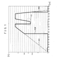
- Fig. 1 is a waveform chart showing an example of a reset signal POR generated by a reset circuit according to an embodiment of the present invention.
- the horizontal axis shows time after power-on (the power is turned on), and the vertical axis shows voltage.
- a power supply voltage VDD gradually rises from 0 V to 3.3 V after power-on, and drops from 3.3 V to 0 V after power-down (the power is turned off).
- the reset signal POR shows a power-on reset signal which becomes low (0 V) when the power supply voltage VDD is lower than a threshold Vth1 and becomes high (power supply voltage VDD) when the power supply voltage VDD is higher than the threshold Vth1.
- the reset signal POR shows a power-down reset signal which becomes high (power supply voltage VDD) when the power supply voltage VDD is higher than a threshold Vth2 and becomes low (0 V) when the power supply voltage VDD is lower than the threshold Vth2.
- the power supply voltage threshold Vth2 at which the power-down reset signal occurs is lower than the power supply voltage threshold Vth1 at which the power-on reset signal occurs. Namely, a hysteresis characteristic that both threshold values are different is provided. If the threshold Vth2 is the same as the threshold Vth1, a change due to noise of the power supply voltage VDD in the neighborhood of the threshold Vth1 such as shown in an area 101 causes a circuit to malfunction since the power-on reset signal and the power-down reset signal are sometimes produced and sometimes not produced. By providing the hysteresis characteristic, in the area 101, erroneous occurrence of the power-on reset signal and the power-down reset signal can be prevented.
- the power-on reset signal POR is used for resetting various circuits such as a ferroelectric memory.
- the power-on reset signal is used, for example, for resetting an initial value of a logic circuit during power-on.
- the power-down reset signal is used, for example, for stopping a circuit operation before the power supply voltage drops during power-down.
- Fig. 2 is a circuit diagram showing a configuration example of a power supply detection circuit according to this embodiment.
- Resistances 201 and 202 are connected in series between a power supply potential vdd and a reference potential Vss.
- a MOS (metal-oxide semiconductor) field effect transistor (FET) is referred to only as a transistor.
- Transistors 203 and 204 compose one inverter. A gate of the p-channel transistor 203 is connected to an interconnection point between the resistances 201 and 202, a source thereof is connected to the power supply potential vdd, and a drain thereof is connected to a drain of the n-channel transistor 204.
- a gate of the n-channel transistor 204 is connected to the interconnection point between the resistances 201 and 202, a source thereof is connected to the reference potential (ground) vss.
- An interconnection point between the gates is an input terminal of the inverter 203, 204, and an interconnection point between the drains is an output terminal of the inverter 203, 204.
- Inverters 206, 208, and 210 connected in series are connected between the output terminal of the inverter 203, 204 and a terminal pwren.
- a MOS capacitor 205 is composed of a p-channel transistor and connected between the output terminal of the inverter 203, 204 and the power supply potential vdd. Namely, a gate of the p-channel transistor 205 is connected to the output terminal of the inverter 203, 204, and a source and a drain thereof are connected to the power supply potential vdd.
- a MOS capacitor 207 is composed of an n-channel transistor and connected between an output terminal of the inverter 206 and the reference potential vss. Namely, a gate of the n-channel transistor 207 is connected to the output terminal of the inverter 206, and a source and a drain thereof are connected to the reference potential vss.
- a MOS capacitor 209 is connected between an output terminal of the inverter 208 and the power supply potential vdd in the same manner as the MOS capacitor 205.
- Fig. 5A is a waveform chart showing an example of a voltage PWREN of the terminal pwren and the power supply voltage VDD (vdd). Referring to Fig. 5A, the operation of the power supply detection circuit in Fig. 2 will be explained.
- an input voltage of the inverter 203, 204 is low.
- the inverter logically inverts the input voltage and outputs it.
- the inverter 203, 204 operates so as to output a high.
- An input terminal of the inverter 206 is connected to the power supply potential vdd via the MOS capacitor 205, and hence the inverter 206 operates so as to output a low.
- An input terminal of the inverter 208 is connected to the reference potential vss via the MOS capacitor 207, and hence the inverter 208 operates so as to output a high.
- An input terminal of the inverter 210 is connected to the power supply potential vdd via the MOS capacitor 209, and hence the inverter 210 operates so as to outputs a low. Consequently, an initial value of the voltage PWREN of the terminal pwren becomes low (0 V).
- the inverter 203, 204 can be inverted after the power supply potential vdd rises sufficiently.
- Fig. 3 is a circuit diagram showing a configuration example of an output circuit to output the power-on reset signal.
- a negative logical product (NAND) circuit 301 inputs signals of the terminal pwren and a terminal porx and outputs a NAND signal thereof.
- the terminal pwren is the same as the output terminal pwren in Fig. 2.
- the terminal porx is the same as an output terminal porx of an inverter 313.
- An input terminal of an inverter 302 is connected to an output terminal of the NAND circuit 301, and an output terminal thereof is connected to a gate of an n-channel transistor 303.
- a source of the n-channel transistor 303 is connected to the reference potential vss, and a drain thereof is connected to a node NH.
- a gate of a p-channel transistor 304 is connected to a node NL, a source thereof is connected to the power supply potential vdd, and a drain thereof is connected to the node NH.
- a gate of an n-channel transistor 305 is connected to the node NL, a source thereof is connected to the reference potential vss, and a drain thereof is connected to the node NH.
- a gate of a p-channel transistor 306 is connected to the node NH, a source thereof is connected to the power supply potential vdd, and a drain thereof is connected to the node NL.
- a gate of an n-channel transistor 307 is connected to the node NH, a source thereof is connected to the reference potential vss, and a drain thereof is connected to the node NL.
- a MOS capacitor 308 is composed of a p-channel transistor and connected between the power supply potential vdd and the node NH.
- a MOS capacitor 309 is composed of an n-channel transistor and connected between the reference potential vss and the node NL.
- Inverters 311, 312, and 313 corrected in series are connected between the node NL and the terminal porx.
- An input terminal of an inverter 314 is connected to the terminal porx, and an output terminal thereof is connected to a terminal por.
- the reset signal POR in Fig. 1 is outputted from the terminal por.
- a transistor 310 is provided to balance with the transistor 303, an inverter 315 is provided to balance with the inverter 311, and an inverter 316, 317 is provided to balance with the inverter 312, and they exert no influence on the operation.
- the transistors 304 and 305 compose one inverter.
- the transistors 306 and 307 compose one inverter.
- the inverter 304, 305 and the inverter 306, 306 compose one latch circuit, which stores a state. Namely, an input terminal of the inverter 304, 305 is connected to an output terminal of the inverter 306, 307, and an input terminal of the inverter 306, 307 is connected to an output terminal of the inverter 304, 305.
- Manufacturing is performed so that the threshold voltage of the transistor 305 is high and the threshold voltage of the transistor 307 is low.
- the threshold voltages of the transistors 304 and 306 are set similarly. Thereby, at power-on, the node NH operates so as to go high, and the node NL operates so as to go low. Moreover, the node NH tries to go high since it is connected to the power supply potential vdd via the MOS capacitor 308, and the node NL tries to go low since it is connected to the reference potential vss via the MOS capacitor 309. Consequently, in an initial state during power-on, the node NH goes high and the node NL goes low.
- the voltage PWREN of the terminal pwren is low until the point in time t1 in Fig. 5A, whereby the NAND circuit 301 outputs a high, and the inverter 302 inputs a low.
- the gate voltage of the transistor 303 goes low, whereby the transistor 303 is turned off.
- the nodes NH and NL remain in the aforementioned initial state. Since the node NL is low, the terminal porx is high, and the voltage POR (Fig. 1) of the terminal por is low.
- Fig. 4 is a circuit diagram showing a configuration example of an output circuit to output the power-on reset signal and the power-down reset signal.
- the output circuit in Fig. 4 is configured by adding the following circuit to the output circuit in Fig. 3.
- a gate of an n-channel transistor 401 is connected to a terminal resetctl, a drain thereof is connected to the power supply potential vdd, and a source thereof is connected to the node NH.
- a gate of an n-channel transistor 402 is connected to the terminal resetctl, a source thereof is connected to the reference potential vss, and a drain thereof is connected to the node NL. The voltage of the terminal resetctl will be explained later with reference to Fig. 6.
- a gate of a p-channel transistor 403 is connected to the terminal pwren (Fig. 2), a source thereof is connected to the power supply potential vdd, and a drain thereof is connected to a source of a p-channel transistor 404.
- a gate of the p-channel transistor 404 is connected to the terminal porx, and a drain thereof is connected to a terminal resetgo.
- This terminal porx is the same as the output terminal porx of the inverter 313.
- a gate of an n-channel transistor 405 is connected to the terminal porx, a source thereof is connected to the reference potential vss, and a drain thereof is connected to the terminal resetgo.
- An input terminal of an inverter 408 is connected to the terminal resetgo, and an output terminal thereof is connected to gates of transistors 406 and 407.
- a source of the p-channel transistor 406 is connected to the power supply potential vdd, and a drain thereof is connected to the terminal resetgo.
- a source of the n-channel transistor 407 is connected to the reference potential vss, and a drain thereof is connected to the terminal resetgo.
- Fig. 5B is a waveform chart showing an example of a voltage RESETGO of the terminal resetgo and the power supply voltage VDD. Referring to Fig. 5B, the operation of the output circuit in Fig. 4 will be explained.
- the transistors 404 and 405 compose one inverter. Until the point in time t2, the voltage RESETGO of the terminal resetgo is low when the terminal porx is high. Moreover, since the voltage PRWEN of the terminal pwren is high when the terminal porx is low, the voltage RESETGO of the terminal resetgo is low. Namely, until the point in time t2, the voltage RESETGO is low.
- the startup signal RESETGO to generate the power-down reset signal during power-down occurs.
- the terminal resetgo sometimes becomes floating and does not rise to the power supply potential vdd, whereby the feedback circuit 406 to 408 is incorporated therein.
- Fig. 6 is a circuit diagram showing a configuration example of a power-down detection circuit.
- a p-channel transistor 601 is diode-connected and connected between the power supply potential vdd and a node mon. Namely, a source of the p-channel transistor 601 is connected to the power supply potential vdd, a gate and a drain thereof are connected to the node mon.
- a MOS capacitor 602 is composed of an n-channel transistor and connected between the node mon and the reference potential vss.
- a gate of an n-channel transistor 603 is connected to a terminal pdx, a source thereof is connected to the node mon, and a drain thereof is connected to a drain of an n-channel transistor 604.
- a gate of the n-channel transistor 604 is connected to the terminal resetgo (Fig. 5), and a source thereof is connected to the reference potential vss.
- a gate of a p-channel transistor 605 is connected to the node mon, a source thereof is connected to the power supply potential vdd, and a drain thereof is connected to a source of a p-channel transistor 606.
- a gate of the p-channel transistor 606 is connected to the node mon, and a drain thereof is connected to a node out1.
- a gate of an n-channel transistor 607 is connected to the node mon, a drain thereof is connected to the node out1, and a source thereof is connected to a drain of an n-channel transistor 608.
- a gate of the n-channel transistor 608 is connected to the node mon, and a source thereof is connected to the reference potential vss.
- a gate of a p-channel transistor 609 is connected to the node out1, a source thereof is connected to the drain of the transistor 605, and a drain thereof is connected to the reference potential vss.
- a gate of an n-channel transistor 610 is connected to the node out1, a source thereof is connected to the drain of the transistor 608, and a drain thereof is connected to the power supply potential vdd.
- Fig. 7A is a waveform chart showing an example of the voltage RESETGO of the terminal resetgo, a voltage RESETCTL of the terminal resetctl, and the power supply voltage VDD
- Fig. 7B is a waveform chart showing an example of a voltage MON of the node mon and-the power supply voltage VDD. Referring to Fig. 7A and Fig. 7B, the operation of the power-down detection circuit in Fig. 6 will be explained.
- the voltage RESETGO is low as explained in Fig. 5B, whereby the transistor (switch element) 604 is off. Since the transistor 601 is diode-connected, the voltage MON of the node mon is lower than the power supply voltage VDD by the threshold voltage of the transistor 601.
- the transistor 604 is turned on.
- the transistor 601 determines the quantity supplied of an electric current
- the transistor 604 determines the quantity discharged of the electric current.
- the transistor 603 is a current limiting element, which can limit and reduce the current flowing between the transistors 601 and 604 (between the power supply potential vdd and the reference potential vss) to reduce power consumption.
- the terminal pdx has a reference voltage (for example, 1.0 V) lower than the power supply voltage VDD, and a generation circuit of this reference voltage will be explained later with reference to Fig. 9.
- the MOS capacitor 602 is a stabilization capacitor and can prevent undershoot of the voltage MON. Namely, by connecting the stabilization capacitor 602 to the node mon, immediately after the transistor 604 is turned on, the potential on the drain side is high, which can prevent a charge from being excessively extracted by high drive capability of the transistor 604 and thereby prevent an erroneous reset signal from being outputted.
- a gate voltage which depends on the power supply voltage VDD and is lower than the power supply voltage VDD, a gate-source voltage vgs of the transistor 603 becomes relatively low when the power supply voltage VDD drops, and hence the transistor 603 does not lose a function as a current limiting element.
- the p-channel transistor 601 has a p-type drain and an n-type well thereunder. This n-type well is connected to the power supply potential vdd.
- vdd the power supply potential
- a charge in the node mon is discharged in a forward direction via a diode of the p-type drain and the n-type well. Consequently, when the power supply voltage VDD drops, thanks to the p-channel transistor 601, the voltage MON can follow the drop in the power supply voltage.
- the transistors 605 to 610 compose a Schmitt circuit.
- the Schmitt circuit is a kind of inverter, and logically inverts an input voltage and then outputs it.
- the Schmitt circuit 605 to 610 outputs a low when the voltage MON is higher than a threshold. As a result, the voltage RESETCTL goes low.
- the Schmitt circuit 605 to 610 outputs a high.
- the inverters 611 and 612 perform amplification, and consequently the voltage RESETCTL goes high.
- the transistor 604 when the voltage RESETGO goes high at the point in time t2, the transistor 604 is turned on and extracts the charge from the monitor node mon, and thereby the voltage MON sharply drops to a level at which the voltage MON is stabilized by a balance between the diode-connected p-channel transistor 601 and the n-channel transistor 604. Thereafter, the voltage MON changes with an inclination determined by the balance between the transistors 601 and 604, following the drop in the power supply voltage VDD. As a result, the voltage MON reaches the threshold of the Schmitt circuit 605 to 610 earlier than the power supply voltage VDD, so that the reset signal RESETCTL is outputted at an appropriate level.
- the current drive capability of the transfer gate 603 lowers by being changed by the power supply voltage VDD even when the power supply voltage VDD drops very slowly, so that the monitoring level MON can be secured, whereby the effect of keeping the threshold Vth2 (Fig. 1) at which the reset signal RESETCTL is generated almost constant independent of the inclination of the fall of the power supply voltage VDD.
- the threshold Vth2 becomes high when the fall speed of the power supply voltage VDD is low, whereas the threshold Vth2 becomes low when the fall speed of the power supply voltage VDD is high. According to the fall speed, the threshold Vth2 changes. According to this embodiment, the monitoring level MON changes to follow the power supply voltage VDD, whereby the fixed threshold Vth2 can be secured irrespective of the fall speed of the power supply voltage VDD.
- the Schmitt circuit 605 to 610 has a hysteresis characteristic that a threshold when the input voltage rises and a threshold when the input voltage drops are different.
- the operation when the input voltage MON drops is important, and the operation when the input voltage MON rises need not be considered. Therefore, the transistor 609 may be eliminated.
- the Schmitt circuit 605 to 606 may be replaced with a simple inverter. Namely, it is required to eliminate the transistors 605, 608 to 610, connect the source of the p-channel transistor 606 to the power supply potential vdd, and connect the source of the n-channel transistor 607 to the reference potential vss.
- the Schmitt circuit can ensure a stable high-precision operation since it has a characteristic that its output voltage changes more sharply as compared with the change of its input voltage.
- Fig. 8 is a circuit diagram showing a configuration example of another power-down detection circuit substituted for the power-down detection circuit in Fig. 6.
- the circuit in Fig. 8 is configured by adding a p-channel transistor 801 to the circuit in Fig. 6.
- a gate of the p-channel transistor 801 is connected to a terminal V1, a source thereof is connected to the power supply potential vdd, and a drain thereof is connected to the node mon. Namely, the transistor 801 is connected in parallel with the transistor 601.
- the charge is supplied to the monitoring level MON from the diode-connected transistor 601, and given to the voltage which has dropped by the threshold voltage of the transistor 601 compared with the power supply voltage VDD.
- the monitoring level MON does not sometimes sufficiently rise.
- the terminal resetctl in Fig. 4 will be explained.
- the voltage RESETCTL of the terminal resetctl changes from low to high at the point in time t3 in Fig. 7A.
- the transistors 401 and 402 are off.
- the terminal resetctl goes high at the point in time t3, the transistors 401 and 402 are turned on.
- the node NH is reset high, and the node NL is reset low. Consequently, the terminal porx goes high, and the terminal por goes low.
- the voltage POR of the terminal por goes low.
- the aforementioned reset signal POR during power-down becomes a power-down reset signal.
- the voltage RESETGO of the terminal resetgo goes low. Since the nodes NH and NL are reset as described above, the reset signal POR can be normally generated without malfunction even if the power is turned on again immediately after power-down. Namely, the waiting time from power-down to the next power-on can be shortened.
- the power supply returns instantaneously after an instantaneous power supply voltage drop after power-on.
- the p-channel transistor 601 includes the p-type drain and the n-type well thereunder. This n-type well is connected to the power supply potential vdd.
- the power suppy potential vdd becomes 0 V
- the charge in the node mon is discharged in a forward direction via the diode of the p-type drain and the n-type well.
- the Schmitt circuit 605 to 610 cannot output a high since the power supply potential vdd drops instantaneously to 0 V. Namely, the reset signal RESETCTL cannot output a high. Thereafter, when the power supply potential Vdd returns instantaneously, the Schmitt circuit 605 to 610 outputs a high, and the reset signal RESETCTL goes high. As a result, the node NH in Fig. 4 is reset high, and the node NL is reset low, which makes a normal operation possible.
- Fig. 9 is a circuit diagram showing a generation circuit of a reference voltage to be inputted to the terminal pdx in Fig. 8.
- a source of a p-channel transistor 901 is connected to the power supply potential vdd, a gate and a drain thereof are connected to a terminal pd3.
- a gate of an n-channel transistor 902 is connected to the power supply potential vdd, a drain thereof is connected to the terminal pd3, and a source thereof is connected to a terminal outx1.
- a gate of an n-channel transistor 903 is connected to the power supply potential vdd, a drain thereof is connected to the terminal outx1, and a source thereof is connected to the terminal pdx.
- a gate of an n-channel transistor 904 is connected to the power supply potential vdd, a drain thereof is connected to the terminal pdx, and a source thereof is connected to a terminal outx0.
- a gate and a drain of an n-channel transistor 905 are connected to the terminal outx0, and a source thereof is connected to the reference potential vss.
- the p-channel transistor 901 is diode-connected and connected to the power supply potential vdd.
- the n-channel transistor 905 is diode-connected and connected to the reference potential vss. Between the transistors 901 and 905, three transistors 902 to 904 are connected in series. The transistors 902 to 904 function as resistances.
- Fig. 10 is a graph showing reference voltages of the terminals pd3, outx1, pdx, and outx0 in Fig. 9.
- the horizontal axis shows the power supply voltage VDD, and the vertical axis shows reference voltage.
- the reference voltage of each terminal shows a voltage value with respect to temperature change from 0°C to 70°C.
- an upper characteristic line shows a reference voltage at 70°C
- a lower characteristic line shows a reference voltage at 0°C.
- an upper characteristic line shows a reference voltage at 0°C
- a lower characteristic line shows a reference voltage at 70°C.
- the characteristics of the reference voltages of the terminals pd3, outx1, and outx0 change in relation to temperature change.
- the characteristic of the reference voltage of the terminal pdx is almost the same even if the temperature is changed from 0°C to 70°C.
- the reference potential of the terminal pdx which is hardly temperature-dependent is used as a gate potential of the transistor 603 in Fig. 8.
- the circuit in Fig. 8 can prevent characteristic change due to temperature.
- Fig. 11 is a circuit diagram showing a configuration example of another power supply detection circuit substituted for the power supply detection circuit in Fig. 2.
- the circuit in Fig. 11 is configured by eliminating the resistances 201 and 202 in the circuit in Fig. 2 and adding the terminal pdx.
- the terminal pdx is connected to the gates of the transistors 203 and 204, and the reference voltage generated by the reference voltage generation circuit in Fig. 9 is applied thereto.
- the circuit in Fig. 11 performs the same operation as the circuit in Fig. 2.
- the reference voltage generation circuit in Fig. 9 is used as a circuit which generates the reference voltage of the terminal pdx of both the power supply detection circuit in Fig. 2 and the power-down detection circuit in Fig. 8, which makes a reduction in circuit scale possible. Moreover, the temperature dependency of the circuit operation can be reduced.
- the power supply detection circuit in Fig. 2 outputs the high-level voltage PWREN when a first voltage according to the power supply voltage is higher than a first threshold and outputs the low-level voltage PWREN when the first voltage is lower than the first threshold during power-on and power-down.
- the power-down detection circuit in Fig. 6 outputs the reset signal RESETCTL when the voltage MON according to the power supply voltage VDD becomes lower than a second threshold after the low-level voltage PWREN is outputted during power-down.
- the reset circuit in this embodiment is obtained by uniting the power-on reset circuit to generate the power-on reset signal and the power-down reset circuit to generate the power-down reset signal.
- the power supply detection circuit is used both when the power-on reset signal is generated and when the power-down reset signal is generated, which makes it possible to realize the small-sized reset circuit.
- the power-down detection circuit detects power-down according to the output of the low-level voltage PWREN during power-down, which facilitates the timing control of the power-down reset signal during power-down, so that a poor startup when the power is repeatedly turned on/off can be prevented.
- This embodiment aims at a more stable circuit characteristic by adding a self-reset function having a hysteresis characteristic to "a circuit which converts the level of a power supply voltage, receives an output thereof by an inverter or the like, and generates a reset signal at a threshold of the inverter".
- the added function is the hysteresis characteristic which is indispensable as a characteristic of a power supply detection circuit.
- the Schmitt circuit is well-known as a circuit having this hysteresis characteristic.
- the power supply detection circuit has a danger of oscillating, and to avoid this danger, the provision of a dead zone using the Schmitt circuit is thought of.
- the dead zone of the Schmitt circuit utilizes feedback, whereby the width of the dead zone changes greatly according to the power supply voltage. Therefore, a characteristic ideal for the power supply detection circuit cannot be obtained by the Schmitt circuit alone since in addition to a change in transistor characteristic according to the process parameter, there is a change in dead zone width according to the level of the power supply voltage.
- the lower the power supply voltage the narrower the dead zone width becomes, whereby the hysteresis characteristic cannot be expected at a low power supply voltage.
- the hysteresis characteristic is realized by the threshold of the transistor 601 and the balance between the p-channel transistor 601 and the n-channel transistor 604 without using relative feedback.
- the minimum hysteresis is almost ensured by the threshold of the transistor 601, and moreover, by using the balance between the p-channel transistor 601 and the n-channel transistor 604, the control potential MON of the circuit which generates the reset signal RESETCTL by a characteristic dependent on the fall speed of the power supply voltage changes, whereby the reset timing independent of the fall speed of the power supply voltage can be controlled.
- the nodes NH and NL of the reset circuit can be forcibly initialized, which makes it possible to reduce the waiting time until the charges in the nodes NH and NL are extracted to the shortest possible time and hold down the occurrence rate of a poor startup of the reset circuit.
- a reset is triggered during power-down, as in the case where power is turned on, the potentials of the nodes are determined respectively with the rise of the power supply voltage, and without the entire circuit being brought into an initial state, the nodes are forcibly shifted to the initial state at the stage where the reset is triggered, whereby instability at the time of state transition can be eliminated. Moreover, once a reset is triggered, the initial state can be ensured, whereby it is unnecessary to provide a waiting time until the charges in the critical nodes NH and NL are extracted after the power supply voltage drops to the ground. Since the critical nodes NH and NH are initialized, a normal operation becomes possible in the next cycle even if the power supply voltage does not drop to the ground.
- One circuit is used as both the power supply detection circuit during power-on and the power supply detection circuit during power-down, which can reduce the number of elements in the circuit. Furthermore, the power supply detection circuit during power-on and the power-down detection circuit to trigger a reset during power-down are synchronized, and hence the hysteresis characteristic is difficult to degrade even if there is a process change.
- Fig. 12 is a circuit diagram showing a configuration example of still another power supply detection circuit substituted for the power supply detection circuit in Fig. 11.
- the circuit in Fig. 12 is configured by eliminating the transistors 203 and 204 from the circuit in Fig. 11 and adding the transistors 1201 to 1206 and the MOS capacitor 1207 thereto.
- the circuit of the transistors 901 to 905 to generate the reference voltage of the terminal pdx is the same as that in Fig. 9. Points in which the circuit in Fig. 12 is different from the circuit in Fig. 11 will be explained below.
- Gates of p-channel transistors 1201 to 1203 are connected to the reference potential vss.
- a source of the transistor 1201 is connected to the power supply potential vdd, a drain thereof is connected to a source of the transistor 1202.
- a source of the transistor 1203 is connected to a drain of the transistor 1202, and a drain thereof is connected to a node pd4.
- three transistors 1201 to 1203 are connected in series between the power supply potential vdd and the node pd4.
- the node pd4 is connected to the input terminal of the inverter 206.
- a gate of an n-channel transistor 1204 is connected to the terminal pdx, a drain thereof is connected to the node pd4, a source thereof is connected to a drain of an n-channel transistor 1205.
- a gate of the transistor 1205 is connected to the power supply potential vdd, and a source thereof is connected to a drain of an n-channel transistor 1206.
- a gate of the transistor 1206 is connected to the terminal pdx, and a source thereof is connected to the reference potential vss. Namely, three transistors 1204 to 1206 are connected in series between the node pd4 and the reference potential vss.
- the transistor 1205 functions as a resistance.
- the terminal pdx may be connected to the gate of the transistor 1205.
- a MOS capacitor 1207 is composed of an n-channel transistor, and connected between the terminal pdx and the reference potential vss.
- the MOS capacitor 1207 has a function of leading the initial value of the terminal pdx to a low level and a function as a stabilization capacitor.
- the transistors 1201 to 1206 have the same function as the inverter of the transistors 203 and 204 in Fig. 11.
- the transistors 1201 to 1203 function as resistances.
- the power supply detection circuit in Fig. 12 can perform the same operation as the power supply detection circuits in Fig. 2 and Fig. 11.
- the threshold of the inverter composed of the transistors 203 and 204 should be raised. However, it is not easy to raise the threshold thereof.
- the circuit in Fig. 12 has the advantage of being able to easily raise the threshold of the n-channel transistors 1204 and 1206. Furthermore, the circuit in Fig. 12 can prevent a bad influence exerted by threshold change due to process variation of the p-channel transistor 203 in Fig. 11.
- the leakage current I1 is a current flowing through the transistors 901 to 905.
- the leakage current I2 is a current flowing through the transistors 1201 to 1203.
- Fig. 13 is a circuit diagram showing a configuration example of yet another power supply detection circuit substituted for the power supply detection circuit in Fig. 12, and Fig. 14 is a timing chart for explaining the operation thereof.
- the circuit in Fig. 13 is configured by adding an inverter 1301 and a p-channel transistor 1302 to the circuit in Fig. 12. This addition can be realized by changing wiring of a mealy layer of a semiconductor device, and the circuit in Fig 12 and the circuit in Fig. 1e can be switched easily. Points in which the circuit in Fig. 13 is different from the circuit in Fig. 12 will be explained below.
- the gate of the p-channel transistor 1201 is connected to the terminal pwren.
- the inverter 1301 logically inverts the voltage of the terminal pwren and outputs it to the gate of the n-channel transistor 904.
- This transistor 904 is a transistor connected between the terminal pdx and the reference potential vss.
- the circuit in Fig. 12 generates the power-on reset signal and the power-down reset signal, and hence needs to always monitor the power supply voltage VDD. As a result, constantly the currents I1 and 12 flow and electric power is consumed. However, depending on uses of the reset circuit, the power-down reset signal is sometimes unnecessary. In other words, the time until a charge remaining in an internal node of the circuit is discharged can be sometimes secured. Hence, in the circuit in Fig. 13, only power-on can be detected, and the stand-by currents I1 and I2 can be cut off.
- a gate of the p-channel transistor 1302 is connected to the power supply potential vdd, and a source and a drain thereof is connected to the terminal pdx. After the transistor 904 is turned off, the terminal pdx remains high. After the transistor 1201 is turned off, the node pd4 remains low.
- the power supply returns instantaneously after an instantaneous power supply voltage drop after the detection of power-on, a charge remains in the terminal pdx during this period of time, which causes a problem that the terminal pdx remains high and the reset signal POR also remains high.
- the charge in the pdx can be discharged and extracted in the case of the instantaneous power supply voltage drop.
- the p-channel transistor 1302 includes a p-type drain, a p-type source, and an n-type well thereunder. This n-type well is connected to the power supply potential vdd.
- the power supply potential vdd drops, the charge in the terminal pdx is discharged in a forward direction via a diode of the p-type drain (source) and the n-type well. Therefore, when the power-supply voltage VDD drops instantaneously, the terminal pdx can follow the power supply voltage drop thanks to the p-channel transistor 1302. As a result, even in the case of the instantaneous power supply voltage drop, the reset signal POR can become 0 V following the power supply voltage VDD. When the power supply returns, the terminal pwren changes from low to high, and the critical nodes NH and NL can be reset.
- the reset signal POR also changes from low to high, and thereby the power-on reset signal is generated.
- a current I flows in a pulse form.
- the current I indicates a total current of the whole reset circuit.
- a standby current 1402 which is a total leakage current of the leakage currents I1 and I2 flows.
- the leakage currents I1 and I2 can be prevented, and hence a standby current 1401 can be 0 V.
- the power supply voltage VDD drops.
- the reset signal POR drops while keeping the same voltage as the power supply voltage VDD, so that the power-down reset signal is not generated.
- a period T1 is a period from when the power supply voltage VDD becomes 0 V by power-down until power-on is detected again.
- the p-channel transistor 1302 When the p-channel transistor 1302 is not provided, the charge in the terminal pdx remains without being discharged after power-down, and therefore the period T1 needs to be made longer. Namely, unless the period T1 from power-down to the next power-on is made longer, the power-on reset signal cannot be generated.
- the p-channel transistor 1302 the charge in the terminal pdx after power-down can be discharged, and the period T1 can be made shorter.
- the power supply voltage VDD makes an instantaneous power supply voltage drop, and the power supply returns instantaneously. Thanks to the p-channel transistor 1302, when the power supply voltage VDD drops instantaneously, the terminal pdx can follow the power supply voltage drop. As a result, even in the case of the instantaneous power supply voltage drop, the reset signal POR can become 0 V, following the power supply voltage VDD.
- the output terminal pwren changes from low to high, and the current I flows in a pulse form.
- the reset signal POR changes from low to high. Thereby, the critical nodes NH and NL can be reset.
- the power supply voltage VDD drops.
- the reset signal POR drops while keeping the same voltage as the power supply voltage VDD, so that the power-down reset signal is not generated.
- Fig. 15 is a circuit diagram showing a configuration example of still yet another power supply detection circuit substituted for the power supply detection circuit in Fig. 13.
- a circuit mode in Fig. 12 and a circuit mode in Fig. 13 can be switched.
- the circuit in Fig. 15 is configured by eliminating the inverter 1301 from the circuit in Fig. 13 and adding a NAND circuit 1501 and an inverter 1502 thereto. Points in which the circuit in Fig. 15 is different from the circuit in Fig. 13 will be explained below.
- the NAND circuit 1501 inputs signals of the terminal pwren and a terminal pdctl and outputs a NAND signal thereof.
- the inverter 1502 logically inverts an output signal of the NAND circuit 1501 and outputs it.
- the gate of the n-channel transistor 904 is connected to an output terminal of the NAND circuit 1501.
- the gate of the p-channel transistor 1201 is connected to an output terminal of the inverter 1502.
- the NAND circuit 1501 When the terminal pdctl has the reference potential vss, the NAND circuit 1501 outputs a high irrespective of the voltage of the terminal pwren.
- the n-channel transistor 904 is turned on since its gate goes high.
- the p-channel transistor 1201 is turned on since its gate goes low. Namely, the circuit in Fig. 15 becomes the same as the circuit in Fig. 12.
- the NAND circuit 1501 When the terminal pdctl has the power supply potential vdd, the NAND circuit 1501 outputs a logical inversion signal of the signal of the terminal pwren. Namely, the circuit in Fig. 15 becomes the same as the circuit in Fig. 13.
- the circuit mode in Fig. 12 can be set, and by applying the power supply potential vdd to the terminal pdctl, the circuit mode in Fig. 13 can be set.
- the circuit modes can be switched logically by a control signal of the terminal pdctl without changing a metal layer.
- a reset circuit includes a power supply detection circuit, a power-down detection circuit, and an output circuit.
- the power supply detection circuit outputs a first signal when a first voltage according to a power supply voltage is higher than a first threshold and outputting a second signal when the first voltage is lower than the first threshold during power-on and power-down.
- the power-down detection circuit outputs a third signal when a second voltage according to the power supply voltage becomes lower than a second threshold after the second signal is outputted during power-down.
- the output circuit outputs a power-on reset signal which changes from low to high when the first signal is outputted during power-on and outputs a power-down reset signal which changes from low to high when the third signal is outputted during power-down.
- the reset circuit is obtained by uniting the power-on reset circuit to generate the power-on reset signal and the power-down reset circuit to generate the power-down reset signal.
- the power supply detection circuit is used both when the power-on reset signal is generated and when the power-down reset signal is generated, whereby the small-sized reset circuit can be realized.
- the power-down detection circuit detects power-down according to the output of a second signal during power-down, which facilitates the timing control of the power-down reset signal during power-down, so that a poor startup when the power is repeatedly turned on/off can be prevented.
Landscapes
- Electronic Switches (AREA)
Applications Claiming Priority (2)
| Application Number | Priority Date | Filing Date | Title |
|---|---|---|---|
| JP2004177099 | 2004-06-15 | ||
| JP2004177099A JP4504108B2 (ja) | 2004-06-15 | 2004-06-15 | リセット回路 |
Publications (3)
| Publication Number | Publication Date |
|---|---|
| EP1608067A2 true EP1608067A2 (de) | 2005-12-21 |
| EP1608067A3 EP1608067A3 (de) | 2006-11-22 |
| EP1608067B1 EP1608067B1 (de) | 2008-12-17 |
Family
ID=34927537
Family Applications (1)
| Application Number | Title | Priority Date | Filing Date |
|---|---|---|---|
| EP04028059A Expired - Fee Related EP1608067B1 (de) | 2004-06-15 | 2004-11-25 | Rücksetzschaltung |
Country Status (6)
| Country | Link |
|---|---|
| US (1) | US7545186B2 (de) |
| EP (1) | EP1608067B1 (de) |
| JP (1) | JP4504108B2 (de) |
| KR (1) | KR100618518B1 (de) |
| CN (1) | CN100347959C (de) |
| DE (1) | DE602004018472D1 (de) |
Cited By (2)
| Publication number | Priority date | Publication date | Assignee | Title |
|---|---|---|---|---|
| WO2011060248A3 (en) * | 2009-11-13 | 2011-09-09 | Marvell World Trade Ltd. | Clock turn-on strategy for power management |
| TWI400883B (zh) * | 2008-04-21 | 2013-07-01 | Realtek Semiconductor Corp | 用以放大訊號時差之時間放大器及其方法 |
Families Citing this family (33)
| Publication number | Priority date | Publication date | Assignee | Title |
|---|---|---|---|---|
| JP4528254B2 (ja) * | 2005-11-25 | 2010-08-18 | 富士通セミコンダクター株式会社 | 電源電圧検出回路 |
| JP4786369B2 (ja) * | 2006-02-23 | 2011-10-05 | 富士通セミコンダクター株式会社 | 電源検出回路 |
| US7659758B2 (en) * | 2006-11-27 | 2010-02-09 | Fujitsu Microelectronics Limited | Reset circuit and system having reset circuit |
| JP4946521B2 (ja) * | 2006-11-27 | 2012-06-06 | 富士通セミコンダクター株式会社 | リセット回路およびリセット回路を備えたシステム |
| JP2009087398A (ja) * | 2007-09-27 | 2009-04-23 | Toshiba Corp | 電源回路 |
| KR100891389B1 (ko) * | 2007-11-02 | 2009-04-02 | 주식회사 하이닉스반도체 | 반도체 소자의 파워 온 리셋 회로 |
| JP4924375B2 (ja) * | 2007-11-15 | 2012-04-25 | 三菱電機株式会社 | パワー素子駆動用回路 |
| KR100937948B1 (ko) * | 2008-06-04 | 2010-01-21 | 주식회사 하이닉스반도체 | 파워 업 신호 생성회로와 생성 방법 |
| US7786770B1 (en) * | 2008-09-30 | 2010-08-31 | Altera Corporation | Reducing power consumption by disabling power-on reset circuits after power up |
| JP5225876B2 (ja) * | 2009-01-29 | 2013-07-03 | セイコーインスツル株式会社 | パワーオンリセット回路 |
| JP4866929B2 (ja) | 2009-03-11 | 2012-02-01 | ザインエレクトロニクス株式会社 | パワーオンリセット回路 |
| KR101003151B1 (ko) * | 2009-05-14 | 2010-12-21 | 주식회사 하이닉스반도체 | 반도체 메모리 장치의 파워 업 신호 생성 회로 |
| CN101882926B (zh) * | 2010-06-24 | 2016-03-23 | 深圳市中庆微科技开发有限公司 | 一种恒流驱动芯片上电复位电路 |
| JP5593917B2 (ja) * | 2010-07-26 | 2014-09-24 | ミツミ電機株式会社 | リセット回路及びそれを備える装置 |
| JP5828621B2 (ja) * | 2010-08-25 | 2015-12-09 | キヤノン株式会社 | 電力供給回路、該回路を備えた機器、及び電力供給回路の制御方法 |
| CN102882497B (zh) * | 2012-09-27 | 2015-02-18 | 电子科技大学 | 一种低功耗高可靠性上电复位电路 |
| CN103532531A (zh) * | 2013-10-12 | 2014-01-22 | 中山大学 | 一种上电复位电路及方法 |
| KR20170006980A (ko) | 2015-07-10 | 2017-01-18 | 에스케이하이닉스 주식회사 | 파워 온 리셋 회로 및 이를 포함하는 반도체 메모리 장치 |
| CN105049028B (zh) * | 2015-08-20 | 2018-10-16 | 上海华力微电子有限公司 | 一种防止i/o电路不确定态的上电检测电路 |
| US10644693B2 (en) * | 2015-10-20 | 2020-05-05 | Texas Instruments Incorporated | Power-on reset circuit with reset transition delay |
| CN105281726B (zh) * | 2015-11-20 | 2018-06-19 | 中国科学院微电子研究所 | 一种上电复位电路 |
| CN106027006B (zh) * | 2016-05-18 | 2019-02-05 | 上海华虹宏力半导体制造有限公司 | 上电复位电路 |
| KR102475458B1 (ko) | 2016-05-30 | 2022-12-08 | 에스케이하이닉스 주식회사 | 파워 온 리셋 회로 및 이를 포함하는 반도체 메모리 장치 |
| CN106054087A (zh) * | 2016-07-15 | 2016-10-26 | 上海璜域光电科技有限公司 | 一种用于无源射频标签的电源检测电路 |
| CN110147154B (zh) * | 2018-02-13 | 2022-11-08 | 北京京东尚科信息技术有限公司 | 实现掉电上电的方法、装置和电路 |
| CN108752681B (zh) * | 2018-04-10 | 2020-09-25 | 衢州蓝然新材料有限公司 | 带网布支撑的聚乙烯/聚苯乙烯复合膜卷及其制造方法 |
| TWI641225B (zh) * | 2018-05-03 | 2018-11-11 | 廣達電腦股份有限公司 | 電壓帶通致能電路 |
| CN109617543B (zh) * | 2018-10-11 | 2023-06-27 | 珠海妙存科技有限公司 | 一种精确控制检测阈值的加速掉电和复位方法及电路 |
| JP6792667B2 (ja) * | 2019-05-13 | 2020-11-25 | ウィンボンド エレクトロニクス コーポレーション | 半導体記憶装置 |
| CN110427089A (zh) * | 2019-09-11 | 2019-11-08 | 深圳市富满电子集团股份有限公司 | 适用于led显示屏芯片中的上电复位系统及方法 |
| CN114696816A (zh) * | 2020-12-30 | 2022-07-01 | 圣邦微电子(北京)股份有限公司 | 一种接口电路 |
| WO2023276734A1 (ja) * | 2021-06-28 | 2023-01-05 | ローム株式会社 | パワーオンリセット回路および半導体装置 |
| CN114302305B (zh) * | 2021-12-28 | 2024-01-19 | 荣成歌尔微电子有限公司 | 电源重置电路、asic芯片及麦克风 |
Citations (3)
| Publication number | Priority date | Publication date | Assignee | Title |
|---|---|---|---|---|
| US4611126A (en) * | 1984-10-04 | 1986-09-09 | Werkzeugmaschinenfabrik Oerlikon-Buehrle Ag | Power on/off reset generator |
| US6204701B1 (en) * | 1994-05-31 | 2001-03-20 | Texas Instruments Incorporated | Power up detection circuit |
| US6683481B1 (en) * | 2002-06-03 | 2004-01-27 | Xilinx, Inc. | Power on reset generator circuit providing hysteresis in a noisy power environment |
Family Cites Families (25)
| Publication number | Priority date | Publication date | Assignee | Title |
|---|---|---|---|---|
| JPS56108120A (en) * | 1980-01-31 | 1981-08-27 | Nec Corp | Automatic clearing circuit |
| US4446381A (en) * | 1982-04-22 | 1984-05-01 | Zilog, Inc. | Circuit and technique for initializing the state of bistable elements in an integrated electronic circuit |
| US4807141A (en) * | 1985-12-16 | 1989-02-21 | Pitney Bowes Inc. | Postage meter with microprocessor controlled reset inhibiting means |
| JPH05183416A (ja) | 1991-12-27 | 1993-07-23 | Hitachi Ltd | パワーオンリセット回路 |
| US5212412A (en) * | 1992-10-26 | 1993-05-18 | Codex Corporation | Power on reset circuit having hysteresis inverters |
| US5249227A (en) * | 1992-11-30 | 1993-09-28 | Motorola, Inc. | Method and apparatus of controlling processing devices during power transition |
| FR2699755B1 (fr) * | 1992-12-22 | 1995-03-10 | Sgs Thomson Microelectronics | Circuit de démarrage et de sécurité contre les coupures d'alimentation, pour circuit intégré. |
| US5497112A (en) * | 1994-07-12 | 1996-03-05 | General Instrument Corporation Of Delaware | Power-out reset system |
| JP2877015B2 (ja) * | 1995-02-15 | 1999-03-31 | 株式会社デンソー | パワーオン・パワーオフリセット装置 |
| KR100421523B1 (ko) * | 1995-08-21 | 2004-07-12 | 마츠시타 덴끼 산교 가부시키가이샤 | 전압검지회로,파워온오프리세트회로및반도체장치 |
| US5991887A (en) * | 1996-02-28 | 1999-11-23 | Dallas Semiconductor Corporation | Low power wake up circuitry, with internal power down of the wake up circuitry itself |
| DE69628729D1 (de) * | 1996-03-29 | 2003-07-24 | St Microelectronics Srl | Einschalt-Rücksetzsignal-Generatorschaltung |
| US5686848A (en) * | 1996-04-29 | 1997-11-11 | Mosaid Technologies Inc. | Power-up/power-down reset circuit for low voltage interval |
| US5831460A (en) * | 1997-02-26 | 1998-11-03 | Xilinx, Inc. | Power-on reset circuit with separate power-up and brown-out trigger levels |
| JPH1131956A (ja) * | 1997-07-10 | 1999-02-02 | Toshiba Corp | リセット信号発生回路 |
| US5917255A (en) * | 1998-01-20 | 1999-06-29 | Vlsi Technology, Inc. | Power-on-reset circuit having reduced size charging capacitor |
| US6084446A (en) * | 1998-03-30 | 2000-07-04 | Macronix International Co., Ltd. | Power on reset circuit |
| US6204703B1 (en) * | 1998-12-21 | 2001-03-20 | Samsung Electronics Co., Ltd. | Power on reset circuit with power noise immunity |
| JP4233205B2 (ja) * | 2000-09-28 | 2009-03-04 | シャープ株式会社 | リセット装置、半導体集積回路装置および半導体記憶装置 |
| JP3820913B2 (ja) * | 2001-05-16 | 2006-09-13 | ヤマハ株式会社 | パワー・オン/オフ・リセット回路 |
| JP3456987B2 (ja) * | 2001-12-07 | 2003-10-14 | 松下電器産業株式会社 | 光送信装置 |
| KR100463201B1 (ko) * | 2002-05-28 | 2004-12-23 | 삼성전자주식회사 | 파워 검출 회로, 이를 이용한 플래시 메모리 장치, 그 플래시 메모리 장치의 파워-온 독출 신호 발생 방법 및 플래시 메모리 장치의 안정적인 파워-온 독출 방법 |
| JP3935777B2 (ja) * | 2002-05-28 | 2007-06-27 | 富士通株式会社 | 出力回路装置 |
| KR100487536B1 (ko) * | 2002-08-20 | 2005-05-03 | 삼성전자주식회사 | 파워-온 리셋 회로 |
| JP4786369B2 (ja) * | 2006-02-23 | 2011-10-05 | 富士通セミコンダクター株式会社 | 電源検出回路 |
-
2004
- 2004-06-15 JP JP2004177099A patent/JP4504108B2/ja not_active Expired - Fee Related
- 2004-11-25 DE DE602004018472T patent/DE602004018472D1/de active Active
- 2004-11-25 EP EP04028059A patent/EP1608067B1/de not_active Expired - Fee Related
- 2004-11-29 US US10/998,060 patent/US7545186B2/en not_active Expired - Fee Related
- 2004-11-30 CN CNB2004100916851A patent/CN100347959C/zh not_active Expired - Fee Related
- 2004-11-30 KR KR1020040098962A patent/KR100618518B1/ko active IP Right Grant
Patent Citations (3)
| Publication number | Priority date | Publication date | Assignee | Title |
|---|---|---|---|---|
| US4611126A (en) * | 1984-10-04 | 1986-09-09 | Werkzeugmaschinenfabrik Oerlikon-Buehrle Ag | Power on/off reset generator |
| US6204701B1 (en) * | 1994-05-31 | 2001-03-20 | Texas Instruments Incorporated | Power up detection circuit |
| US6683481B1 (en) * | 2002-06-03 | 2004-01-27 | Xilinx, Inc. | Power on reset generator circuit providing hysteresis in a noisy power environment |
Cited By (3)
| Publication number | Priority date | Publication date | Assignee | Title |
|---|---|---|---|---|
| TWI400883B (zh) * | 2008-04-21 | 2013-07-01 | Realtek Semiconductor Corp | 用以放大訊號時差之時間放大器及其方法 |
| WO2011060248A3 (en) * | 2009-11-13 | 2011-09-09 | Marvell World Trade Ltd. | Clock turn-on strategy for power management |
| US8775854B2 (en) | 2009-11-13 | 2014-07-08 | Marvell World Trade Ltd. | Clock turn-on strategy for power management |
Also Published As
| Publication number | Publication date |
|---|---|
| US7545186B2 (en) | 2009-06-09 |
| JP2006005459A (ja) | 2006-01-05 |
| DE602004018472D1 (de) | 2009-01-29 |
| KR20050119078A (ko) | 2005-12-20 |
| KR100618518B1 (ko) | 2006-08-31 |
| CN1713526A (zh) | 2005-12-28 |
| EP1608067A3 (de) | 2006-11-22 |
| US20050275437A1 (en) | 2005-12-15 |
| CN100347959C (zh) | 2007-11-07 |
| EP1608067B1 (de) | 2008-12-17 |
| JP4504108B2 (ja) | 2010-07-14 |
Similar Documents
| Publication | Publication Date | Title |
|---|---|---|
| US7545186B2 (en) | Reset circuit | |
| US7176740B2 (en) | Level conversion circuit | |
| JP6169892B2 (ja) | 半導体集積回路およびその動作方法 | |
| US20220294426A1 (en) | Ultra-low energy per cycle oscillator topology | |
| US7382158B2 (en) | Level shifter circuit | |
| US8575987B2 (en) | Level shift circuit | |
| US6683445B2 (en) | Internal power voltage generator | |
| US9136827B2 (en) | Power-on reset circuit | |
| US7099223B2 (en) | Semiconductor memory device | |
| US7123062B2 (en) | Power-up circuit in semiconductor memory device | |
| JPH11214962A (ja) | 半導体集積回路装置 | |
| US5374923A (en) | Power-on detecting circuit | |
| JP5421075B2 (ja) | 入力回路 | |
| JP3652793B2 (ja) | 半導体装置の電圧変換回路 | |
| US6191624B1 (en) | Voltage comparator | |
| US7372321B2 (en) | Robust start-up circuit and method for on-chip self-biased voltage and/or current reference | |
| US7576575B2 (en) | Reset signal generator in semiconductor device | |
| US6265932B1 (en) | Substrate control voltage circuit of a semiconductor memory | |
| US20060145749A1 (en) | Bias circuit having reduced power-up delay | |
| US11271551B2 (en) | Level shifter | |
| US20100231273A1 (en) | Semiconductor device | |
| JP2000339981A (ja) | 半導体集積回路 | |
| JP2990160B1 (ja) | 電圧発生回路 | |
| KR100268781B1 (ko) | 반도체 장치의 입력 장치 | |
| KR100348301B1 (ko) | 파워 온 리셋 회로 |
Legal Events
| Date | Code | Title | Description |
|---|---|---|---|
| PUAI | Public reference made under article 153(3) epc to a published international application that has entered the european phase |
Free format text: ORIGINAL CODE: 0009012 |
|
| AK | Designated contracting states |
Kind code of ref document: A2 Designated state(s): AT BE BG CH CY CZ DE DK EE ES FI FR GB GR HU IE IS IT LI LU MC NL PL PT RO SE SI SK TR |
|
| AX | Request for extension of the european patent |
Extension state: AL HR LT LV MK YU |
|
| PUAL | Search report despatched |
Free format text: ORIGINAL CODE: 0009013 |
|
| AK | Designated contracting states |
Kind code of ref document: A3 Designated state(s): AT BE BG CH CY CZ DE DK EE ES FI FR GB GR HU IE IS IT LI LU MC NL PL PT RO SE SI SK TR |
|
| AX | Request for extension of the european patent |
Extension state: AL HR LT LV MK YU |
|
| 17P | Request for examination filed |
Effective date: 20070509 |
|
| AKX | Designation fees paid |
Designated state(s): DE FR |
|
| 17Q | First examination report despatched |
Effective date: 20070801 |
|
| GRAP | Despatch of communication of intention to grant a patent |
Free format text: ORIGINAL CODE: EPIDOSNIGR1 |
|
| GRAS | Grant fee paid |
Free format text: ORIGINAL CODE: EPIDOSNIGR3 |
|
| GRAA | (expected) grant |
Free format text: ORIGINAL CODE: 0009210 |
|
| AK | Designated contracting states |
Kind code of ref document: B1 Designated state(s): DE FR |
|
| RAP2 | Party data changed (patent owner data changed or rights of a patent transferred) |
Owner name: FUJITSU MICROELECTRONICS LIMITED |
|
| REF | Corresponds to: |
Ref document number: 602004018472 Country of ref document: DE Date of ref document: 20090129 Kind code of ref document: P |
|
| PLBE | No opposition filed within time limit |
Free format text: ORIGINAL CODE: 0009261 |
|
| STAA | Information on the status of an ep patent application or granted ep patent |
Free format text: STATUS: NO OPPOSITION FILED WITHIN TIME LIMIT |
|
| 26N | No opposition filed |
Effective date: 20090918 |
|
| PGFP | Annual fee paid to national office [announced via postgrant information from national office to epo] |
Ref country code: FR Payment date: 20091203 Year of fee payment: 6 |
|
| REG | Reference to a national code |
Ref country code: FR Ref legal event code: ST Effective date: 20110801 |
|
| PG25 | Lapsed in a contracting state [announced via postgrant information from national office to epo] |
Ref country code: FR Free format text: LAPSE BECAUSE OF NON-PAYMENT OF DUE FEES Effective date: 20101130 |
|
| PGFP | Annual fee paid to national office [announced via postgrant information from national office to epo] |
Ref country code: DE Payment date: 20191112 Year of fee payment: 16 |
|
| REG | Reference to a national code |
Ref country code: DE Ref legal event code: R119 Ref document number: 602004018472 Country of ref document: DE |
|
| PG25 | Lapsed in a contracting state [announced via postgrant information from national office to epo] |
Ref country code: DE Free format text: LAPSE BECAUSE OF NON-PAYMENT OF DUE FEES Effective date: 20210601 |