EP1589074B1 - Conductive polymer gel and process for producing the same, articles and conductive functional members, comprising such gel. - Google Patents
Conductive polymer gel and process for producing the same, articles and conductive functional members, comprising such gel. Download PDFInfo
- Publication number
- EP1589074B1 EP1589074B1 EP04705535A EP04705535A EP1589074B1 EP 1589074 B1 EP1589074 B1 EP 1589074B1 EP 04705535 A EP04705535 A EP 04705535A EP 04705535 A EP04705535 A EP 04705535A EP 1589074 B1 EP1589074 B1 EP 1589074B1
- Authority
- EP
- European Patent Office
- Prior art keywords
- conductive
- polymer gel
- conductive polymer
- gel
- alcohol
- Prior art date
- Legal status (The legal status is an assumption and is not a legal conclusion. Google has not performed a legal analysis and makes no representation as to the accuracy of the status listed.)
- Expired - Lifetime
Links
Images
Classifications
-
- C—CHEMISTRY; METALLURGY
- C08—ORGANIC MACROMOLECULAR COMPOUNDS; THEIR PREPARATION OR CHEMICAL WORKING-UP; COMPOSITIONS BASED THEREON
- C08J—WORKING-UP; GENERAL PROCESSES OF COMPOUNDING; AFTER-TREATMENT NOT COVERED BY SUBCLASSES C08B, C08C, C08F, C08G or C08H
- C08J3/00—Processes of treating or compounding macromolecular substances
- C08J3/02—Making solutions, dispersions, lattices or gels by other methods than by solution, emulsion or suspension polymerisation techniques
- C08J3/03—Making solutions, dispersions, lattices or gels by other methods than by solution, emulsion or suspension polymerisation techniques in aqueous media
- C08J3/075—Macromolecular gels
-
- C—CHEMISTRY; METALLURGY
- C08—ORGANIC MACROMOLECULAR COMPOUNDS; THEIR PREPARATION OR CHEMICAL WORKING-UP; COMPOSITIONS BASED THEREON
- C08L—COMPOSITIONS OF MACROMOLECULAR COMPOUNDS
- C08L65/00—Compositions of macromolecular compounds obtained by reactions forming a carbon-to-carbon link in the main chain; Compositions of derivatives of such polymers
-
- C—CHEMISTRY; METALLURGY
- C09—DYES; PAINTS; POLISHES; NATURAL RESINS; ADHESIVES; COMPOSITIONS NOT OTHERWISE PROVIDED FOR; APPLICATIONS OF MATERIALS NOT OTHERWISE PROVIDED FOR
- C09D—COATING COMPOSITIONS, e.g. PAINTS, VARNISHES OR LACQUERS; FILLING PASTES; CHEMICAL PAINT OR INK REMOVERS; INKS; CORRECTING FLUIDS; WOODSTAINS; PASTES OR SOLIDS FOR COLOURING OR PRINTING; USE OF MATERIALS THEREFOR
- C09D5/00—Coating compositions, e.g. paints, varnishes or lacquers, characterised by their physical nature or the effects produced; Filling pastes
- C09D5/24—Electrically-conducting paints
-
- H—ELECTRICITY
- H01—ELECTRIC ELEMENTS
- H01B—CABLES; CONDUCTORS; INSULATORS; SELECTION OF MATERIALS FOR THEIR CONDUCTIVE, INSULATING OR DIELECTRIC PROPERTIES
- H01B1/00—Conductors or conductive bodies characterised by the conductive materials; Selection of materials as conductors
- H01B1/06—Conductors or conductive bodies characterised by the conductive materials; Selection of materials as conductors mainly consisting of other non-metallic substances
- H01B1/12—Conductors or conductive bodies characterised by the conductive materials; Selection of materials as conductors mainly consisting of other non-metallic substances organic substances
- H01B1/122—Ionic conductors
-
- H—ELECTRICITY
- H01—ELECTRIC ELEMENTS
- H01M—PROCESSES OR MEANS, e.g. BATTERIES, FOR THE DIRECT CONVERSION OF CHEMICAL ENERGY INTO ELECTRICAL ENERGY
- H01M4/00—Electrodes
- H01M4/86—Inert electrodes with catalytic activity, e.g. for fuel cells
- H01M4/8605—Porous electrodes
-
- H—ELECTRICITY
- H01—ELECTRIC ELEMENTS
- H01M—PROCESSES OR MEANS, e.g. BATTERIES, FOR THE DIRECT CONVERSION OF CHEMICAL ENERGY INTO ELECTRICAL ENERGY
- H01M4/00—Electrodes
- H01M4/86—Inert electrodes with catalytic activity, e.g. for fuel cells
- H01M4/8663—Selection of inactive substances as ingredients for catalytic active masses, e.g. binders, fillers
- H01M4/8668—Binders
-
- H—ELECTRICITY
- H01—ELECTRIC ELEMENTS
- H01M—PROCESSES OR MEANS, e.g. BATTERIES, FOR THE DIRECT CONVERSION OF CHEMICAL ENERGY INTO ELECTRICAL ENERGY
- H01M4/00—Electrodes
- H01M4/86—Inert electrodes with catalytic activity, e.g. for fuel cells
- H01M4/8663—Selection of inactive substances as ingredients for catalytic active masses, e.g. binders, fillers
- H01M4/8673—Electrically conductive fillers
-
- H—ELECTRICITY
- H01—ELECTRIC ELEMENTS
- H01M—PROCESSES OR MEANS, e.g. BATTERIES, FOR THE DIRECT CONVERSION OF CHEMICAL ENERGY INTO ELECTRICAL ENERGY
- H01M4/00—Electrodes
- H01M4/86—Inert electrodes with catalytic activity, e.g. for fuel cells
- H01M4/90—Selection of catalytic material
- H01M4/92—Metals of platinum group
- H01M4/925—Metals of platinum group supported on carriers, e.g. powder carriers
- H01M4/926—Metals of platinum group supported on carriers, e.g. powder carriers on carbon or graphite
-
- H—ELECTRICITY
- H01—ELECTRIC ELEMENTS
- H01M—PROCESSES OR MEANS, e.g. BATTERIES, FOR THE DIRECT CONVERSION OF CHEMICAL ENERGY INTO ELECTRICAL ENERGY
- H01M8/00—Fuel cells; Manufacture thereof
- H01M8/10—Fuel cells with solid electrolytes
- H01M8/1004—Fuel cells with solid electrolytes characterised by membrane-electrode assemblies [MEA]
-
- C—CHEMISTRY; METALLURGY
- C08—ORGANIC MACROMOLECULAR COMPOUNDS; THEIR PREPARATION OR CHEMICAL WORKING-UP; COMPOSITIONS BASED THEREON
- C08J—WORKING-UP; GENERAL PROCESSES OF COMPOUNDING; AFTER-TREATMENT NOT COVERED BY SUBCLASSES C08B, C08C, C08F, C08G or C08H
- C08J2300/00—Characterised by the use of unspecified polymers
- C08J2300/12—Polymers characterised by physical features, e.g. anisotropy, viscosity or electrical conductivity
-
- C—CHEMISTRY; METALLURGY
- C08—ORGANIC MACROMOLECULAR COMPOUNDS; THEIR PREPARATION OR CHEMICAL WORKING-UP; COMPOSITIONS BASED THEREON
- C08J—WORKING-UP; GENERAL PROCESSES OF COMPOUNDING; AFTER-TREATMENT NOT COVERED BY SUBCLASSES C08B, C08C, C08F, C08G or C08H
- C08J2381/00—Characterised by the use of macromolecular compounds obtained by reactions forming in the main chain of the macromolecule a linkage containing sulfur with or without nitrogen, oxygen, or carbon only; Polysulfones; Derivatives of such polymers
-
- H—ELECTRICITY
- H01—ELECTRIC ELEMENTS
- H01M—PROCESSES OR MEANS, e.g. BATTERIES, FOR THE DIRECT CONVERSION OF CHEMICAL ENERGY INTO ELECTRICAL ENERGY
- H01M4/00—Electrodes
- H01M4/86—Inert electrodes with catalytic activity, e.g. for fuel cells
- H01M4/90—Selection of catalytic material
- H01M4/92—Metals of platinum group
-
- Y—GENERAL TAGGING OF NEW TECHNOLOGICAL DEVELOPMENTS; GENERAL TAGGING OF CROSS-SECTIONAL TECHNOLOGIES SPANNING OVER SEVERAL SECTIONS OF THE IPC; TECHNICAL SUBJECTS COVERED BY FORMER USPC CROSS-REFERENCE ART COLLECTIONS [XRACs] AND DIGESTS
- Y02—TECHNOLOGIES OR APPLICATIONS FOR MITIGATION OR ADAPTATION AGAINST CLIMATE CHANGE
- Y02E—REDUCTION OF GREENHOUSE GAS [GHG] EMISSIONS, RELATED TO ENERGY GENERATION, TRANSMISSION OR DISTRIBUTION
- Y02E60/00—Enabling technologies; Technologies with a potential or indirect contribution to GHG emissions mitigation
- Y02E60/30—Hydrogen technology
- Y02E60/50—Fuel cells
Definitions
- the present invention relates to a conductive polymer gel which is easily gelatinized and has good conductivity, and to a method of producing the same. More particularly, the present invention relates to an actuator, an iontophoretic patch label, and a biomedical electrode, which employ the conductive polymer gel; a toner which employs the conductive polymer gel; a conductive functional member, an antistatic sheet, and a printed circuit member, which employ the toner; a conductive paste which employs the conductive polymer gel; an electrode for fuel cells, which employs the conductive polymer gel; and a fuel cell which employs the electrode for fuel cells.
- the conductive polymer gel obtained by the prior art and the production method thereof had the following problems.
- the conductive polymer gel disclosed in (1) contains an electrolyte and the electrolyte exhibits conductivity, it may exhibit unstable conductivity or fail to ensure good conductivity when exposed to an atmosphere at a temperature lower than the freezing point of water. That is, it was difficult for the conductive polymer gel of the prior art to maintain good conductivity in an atmosphere at low temperature lower than the freezing point of water.
- the conductive polymer gel disclosed in (2) exhibits conductivity without containing an electrolyte, polymerization and gelation of the monomer must be conducted in the same process, and thus the process is complicated and a high level of technique is required in view of controllability.
- a toner for forming a circuit board a toner comprising a core portion composed of metal particles, and an insulating resin portion, with which the surface of the core portion is coated, is used, as disclosed in Japanese Patent Application, First Publication No. 2002-151828 (Document 3) and Japanese Patent Application, First Publication No. 2003-255594 (Document 4).
- the toner containing metal particles When the toner containing metal particles is used in the production of a printed circuit board and electronic parts, it is difficult to separate metal powders constituting the toner from organic components such as a resin portion upon disposal of the printed circuit board and electronic parts. Therefore, it is difficult to recycle resources.
- the toner for formation of the circuit board of the prior art comprises a core portion made of metal particles and, even if the printed circuit board and electronic parts produced by using the toner are incinerated, the metal component remains.
- a conductive paste is a mixture of a conductive material such as metal powder, and a resin binder.
- the conductive paste is applied on a base material such as resin film or a substrate and is then cured by heating, thereby making it possible to impart conductivity to the base material. Therefore, the conductive paste is employed to form printed circuit boards such as antenna coils for RF-ID (Radio Frequency-Identification), circuit board of printed circuit boards, electrodes of liquid crystal displays, and membranes circuit boards of keyboards.
- the conductive paste is employed to bond terminals and lead wires of electronic parts, and to form an internal conductive film (interlayer connection conductive layer) of a laminated ceramic capacitor.
- Japanese Patent Application, First Publication No. Hei 1-159906 (Document 5) and Japanese Patent Application, First Publication No. Hei 9-306240 (Document 6) disclose a conductive paste comprising a metal powder, as a main component, and a resin vehicle (resin binder) in which the metal powder is dispersed.
- PEFC polymer electrolyte type fuel cell
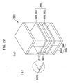
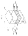
- FIG. 22 is a schematic view showing a cell 3101 constituting a power generation portion of PEFC of the prior art.
- the cell 3101 comprises a polymer electrolyte film 3102, and a fuel electrode (negative electrode) 3131 and an air electrode (positive electrode) 3132 provided at both sides of the polymer electrolyte film 3102.
- the fuel electrode 3131 and the air electrode 3132 which serve as an electrode 3103, is composed of porous supporting layers 3161a and 3161b made of a carbon paper, as a current collector, and catalyst layers 3162a and 3162b provided on the supporting layers 3161a and 3161b.
- the fuel electrode 3131 and the air electrode 3132 are provided at both sides of the polymer electrolyte film 3102 in a state in which the catalyst layers 3162a and 3162b are contacted with the polymer electrolyte film 3102.
- a hydrogen gas is fed to the fuel electrode 3131 and the hydrogen gas is adsorbed to the catalyst layer 3162a on the fuel electrode 3131, and is then converted into hydrogen ions and electrons.
- the resulting hydrogen ions move to the side of the air electrode 3132 in the polymer electrolyte film 3102, together with water, while electrons flow through an external circuit board (not shown) toward the air electrode 3132 from the fuel electrode 3131.
- An oxygen gas is fed to the air electrode 3132 and the oxygen gas is adsorbed to the catalyst layer 3162b on the air electrode 3132, and water is produced from oxygen molecules, and hydrogen ions and electrons moved from the fuel electrode 3131.
- platinum and a platinum alloy are mainly used. Since platinum is expensive, the cost required to produce PEFC increases. To reduce the amount of platinum, various techniques have been reported. However, since catalytic activity is reduced by an influence of catalyst poisoning due to a trace amount of carbon monoxide contained in a hydrogen gas in the fuel electrode 3131, it is necessary to use a large amount of platinum. Therefore, it is difficult to reduce the amount of platinum.
- the fuel electrode 3131 and the air electrode 3132 are respectively composed of two layers, for example, supporting layers 3161a and 3161b and catalyst layers 3162a and 3162b, and each layer has a large thickness. Therefore, reductioon of the thickness of the electrode 3103 and the fuel cell is limited.
- WO 00/02949 A discloses the preparation of PEDOT-PSS/PEO gels to be used in electrodes in electrochemical systems
- WO 02/093256 A discloses at color negative film samples comprising water as main component, a conductive conjugated polymer (Baytron® P), Ethylene glycol, and a coating surfactant.
- the conductive polymer gel of the present invention contains water, as a main component, a conductive conjugated polymers, alkylbenzenesulfonic acid as surfactant and optionally an alcohol.
- the conductive polymer gel of the present invention is formed by gelatinizing a conductive conjugated polymer such as polyacetylene, polyphenylene, polypyrrole, polythiophene, polyfuran, or polyselenophene, and does not contain an electrolyte such as magnesium chloride as an essential component. Since the conductive conjugated polymer constituting the conductive polymer gel containing water, as a main component, a conductive conjugated polymer, alkylbenzenesulfonic acid as surfactant and optionally an alcohol imparts conductivity, the conductive polymer gel can maintain good conductivity even when exposed to an atmosphere at a temperature lower than the freezing point of water.
- a conductive conjugated polymer such as polyacetylene, polyphenylene, polypyrrole, polythiophene, polyfuran, or polyselenophene
- the conductive polymer gel of the present invention can be used for various purposes which require to exhibition of a stable function under such severe conditions that ambient temperature is lower than the freezing point of water, for example, conductive gels having functionality (e.g., response to electrolytic stimulation, response to moisture absorption, heat sensitizing response, etc.) such as electrolytes of cells.
- conductive gels having functionality e.g., response to electrolytic stimulation, response to moisture absorption, heat sensitizing response, etc.
- the conductive polymer gel may contain an electrolyte. In the case in which it contains the electrolyte, the conductive polymer gel is provided with markedly excellent conductivity.
- the conductive conjugated polymer contained in the conductive polymer gel exhibits conductivity without being doped with a dopant even if the electrolyte is not added. Since the conductive conjugated polymer and a gel which employs the same in the present invention are provided with both electrical conduction and ionic conduction, the conductivity is not impaired even when exposed to an atmosphere at a temperature lower than the freezing point of water.
- the conductive conjugated polymer is at least one selected from polyacetylene, polyphenylene, polypyrrole, polythiophene, polyfuran, polyselenophene, polyisothianaphthene, polyphenylene sulfide, polyaniline, polyphenylenevinylene, polythiophenevinylene, poly-perinaphthalene, polyanthracene, polynaphthalene, polypyrene, polyazulene, and derivatives thereof.
- polypyrrole or polythiophene is preferably used because it is excellent in stability, reliability and availability.
- the dopant includes, for example, at least one selected from iodine, arsenic fluoride, iron chloride, perchloric acid, sulfonic acid, perfluorosulfonic acid, polystyrenesulfonic acid, sulfuric acid, hydrochloric acid, nitric acid, and derivatives thereof.
- polystyrenesulfonic acid is preferable because high conductivity can be easily adjusted.
- the surfactant is alkylbenzenesulfonic acid because of its chemical stability after gelation.
- the alcohol includes, for example, at least one selected from isopropyl alcohol, butanol, ethylene glycol, propylene glycol, glycerin, erythritol, polyethylene glycol, polyvinyl alcohol, and derivatives thereof.
- a monohydric alcohol having 3 or more carbon atoms, or polyhydric alcohol is preferable, and ethylene glycol and polyethylene glycol are more preferable.
- alkylbenzenesulfonic acid as a surfactant and optionally an alcohol are added to a conductive conjugated polymer colloidal dispersion and/or a conductive conjugated polymer solution, and then the mixture is left to stand, thereby to gelatinize the conductive conjugated polymer colloidal dispersion and/or the conductive conjugated polymer solution.
- conductive conjugated polymer colloidal dispersion and/or conductive conjugated polymer solution are used as a starting material in the above method, it is not necessary to carry out polymerization and gelation of a monomer in the same process, like the method of the prior art.
- Additives such as alkylbenzenesulfonic acid as a surfactant and optionally an alcohol are added by pouring into the conductive conjugated polymer colloidal dispersion and/or the conductive conjugated polymer solution without forming bubbles.
- the actuator of the present invention comprises an actuator body made of a conductive polymer gel, and the conductive polymer gel contains water, as a main component, a conductive conjugated polymer, alkylbenzenesulfonic acid as a surfactant, and optionally an alcohol.
- the actuator body may have any shape such as strip, spiral, ring, disk, comb, or indeterminate form, it preferably has a strip shape because it is easy to control a force.
- the strip shape does not mean only a precise rectangular solid, and its width and thickness may slightly vary in a longitudinal direction.
- the conductive polymer gel formed into a predetermined shape Only by replacing a dipping solution by water and a solvent such as acetone, the conductive polymer gel formed into a predetermined shape repeatedly expands or shrinks in the longitudinal direction. Therefore, the conductive polymer gel can be employed as the actuator.
- the iontophoretic patch label of the present invention comprises a pad, and electrodes composed of an anode and a cathode provided on one surface of the pad at regular intervals. By contacting an analyte with the other surface of the pad and applying an electric current between the electrodes, a treating agent is locally delivered to the analyte.
- the pad is made of a conductive polymer gel containing water, as a main component, a conductive conjugated polymer, alkylbenzenesulfonic acid as a surfactant, and optionally an alcohol.
- the pad is composed of the conductive polymer gel containing water, as a main component, a conductive conjugated polymer, alkylbenzenesulfonic acid as a surfactant, and optionally an alcohol good balance between electronic conduction and ionic conduction in the pad is maintained. Consequently, the thickness of a gel layer constituting the pad can be reduced, and thus it is made possible to reduce the thickness of the iontophoretic patch label.
- the biomedical electrode of the present invention comprises an electrode device, and a member which electrically and physically connects the electrode device to an analyte.
- the member is made of a conductive polymer gel containing water, as a main component, a conductive conjugated polymer, alkylbenzenesulfonic acid as a surfactant, and optionally an alcohol.
- the member which electrically and physically connects the electrode device to the analyte, is made of a conductive polymer gel containing water, as a main component, a conductive conjugated polymer, alkylbenzenesulfonic acid as a surfactant, and optionally an alcohol and therefore electronic conduction and ionic conduction can be optionally selected according to the conditions for production of the gel. Since the gel is provided with both electronic conduction and ionic conduction, good conductivity can be secured even when the gel layer constituting the member has a small thickness, and thus it is made possible to measure accurately. Furthermore, since the gel can stably retain shape for a long time, it is made possible to electrically and physically connect the electrode device to the analyte, satisfactorily.
- the toner of the present invention comprises a core portion made of a conductive polymer gel containing water, as a main component, a conductive conjugated polymer alkylbenzenesulfonic acid as a surfactant, and optionally an alcohol, and a resin portion provided on the surface of the core portion.
- a toner for formation of wiring of the prior art metal particles have been used as a core portion.
- a conductive polymer gel is used as the core portion in place of conventional metal particles, and thus the content of a metal component in the toner can be reduced as compared with the prior art.
- the core portion has preferably a spherical shape.
- the conductive conjugated polymer may further be doped with a dopant. Consequently, the concentration of a carrier in the conductive polymer gel can be increased and the conductivity can be improved.
- the first conductive functional member of the present invention comprises a base material, and a conductive portion made of a toner provided on at least one surface of the base material.
- the toner comprises a core portion made of a conductive polymer gel containing water, as a main component, a conductive conjugated polymer alkylbenzenesulfonic acid as a surfactant, and optionally an alcohol, and a resin portion provided on the surface of the core portion.
- the antistatic sheet of the present invention comprises a base material, and a conductive portion made of a toner provided on at least one surface of the base material.
- the conductive portion has a planar shape, and the toner comprises a core portion made of a conductive polymer gel containing water, as a main component, a conductive conjugated polymer, alkylbenzenesulfonic acid as a surfactant, and optionally an alcohol, and a resin portion provided on the surface of the core portion.
- the first printed circuit member of the present invention comprises a base material, and a conductive portion made of a toner provided on at least one surface of the base material.
- the conductive portion has a linear shape, and the toner comprises a core portion made of a conductive polymer gel containing water, as a main component, a conductive conjugated polymer, alkylbenzenesulfonic acid as a surfactant, and optionally an alcohol, and a resin portion provided on the surface of the core portion.
- the content of the metal component in the toner is reduced as compared with the toner for formation of wiring of the prior art. Therefore, in the first conductive functional member, the antistatic sheet and the first printed circuit member described above, since the conductive portion is composed of the toner, the content of the metal component can be reduced as compared with the prior art.
- the conductive paste of the present invention comprises a conductive polymer gel containing water, as a main component, a conductive conjugated polymer, alkylbenzenesulfonic acid as a surfactant, and optionally an alcohol a conductive powder; and a resin binder.
- the conductive polymer gel in the conductive paste is the same polymer compound (organic compound) as the resin binder, and is easily miscible and is also excellent in compatibility.
- the conductive conjugated polymer may further be doped with a dopant. Consequently, the concentration of a carrier in the conductive polymer gel can be increased and the conductivity can be improved.
- the second conductive functional member of the present invention comprises a base material, and a conductive portion made of a conductive paste provided on at least one surface of the base material.
- the conductive paste comprises a conductive polymer gel containing water, as a main component, a conductive conjugated polymer, alkylbenzenesulfonic acid as a surfactant, and optionally an alcohol; a conductive powder; and a resin binder.
- the second printed circuit member of the present invention comprises a base material, and a conductive portion made of a conductive paste provided on at least one surface of the base material.
- the conductive portion has a linear shape, and the conductive paste comprises a conductive polymer gel containing water, as a main component, a conductive conjugated polymer, alkylbenzenesulfonic acid as a surfactant, and optionally an alcohol; a conductive powder; and a resin binder. Consequently, in the second conductive functional member and the second printed circuit member, the content of the conductive powder required to obtain sufficient conductivity can be reduced as compared with the prior art.
- the second printed circuit member serves as an antenna having a linear shape, and an IC chip may be connected to the antenna. Consequently, it can be used as a non-contact type IC media.
- the electrode for fuel cell of the present invention comprises a conductive polymer gel containing water, as a main component, a conductive conjugated polymer, and a alkylbenzenesulfonic acid as a surfactant, and optionally an alcohol.
- the conductive polymer gel As a fuel electrode, a hydrogen gas is dissolved in water contained in the conductive polymer gel, thereby making it possible to dissociate into hydrogen ions and electrons.
- an oxygen gas can be incorporated by dissolving in water contained in the conductive polymer gel. Therefore, the electrode for fuel cells, comprising a supporting layer, on which a catalyst layer made of platinum is supported, of the prior art can be replaced by the conductive polymer gel.
- the conductive conjugated polymer may further be doped with a dopant. Consequently, the concentration of a carrier in the polymer gel can be increased and the conductivity can be improved.
- the fuel cell of the present invention is a fuel cell comprising a power generation portion composed of one or more cells stacked with each other, each cell comprising first and second electrodes, and an electrolyte interposed between the electrodes, wherein the first electrode and/or the second electrode comprise a conductive polymer gel containing water, as a main component, a conductive conjugated polymer alkylbenzenesulfonic acid as a surfactant, and optionally an alcohol.
- an electrode for fuel cells can be produced at low cost as compared with the case of using a supporting layer, on which a catalyst layer made of platinum is supported, of the prior art, and it is made possible to reduce the thickness of a power generator which employs the fuel cell.
- alkylbenzenesulfonic acid as a surfactant, and optionally an alcohol are added to a conductive conjugated polymer colloidal dispersion and/or a conductive conjugated polymer solution (hereinafter referred to as a conductive conjugated polymer colloidal dispersion), or a conductive conjugated polymer colloidal dispersion doped with a dopant, and then the mixture is left to stand under gelation conditions. Consequently, the conductive conjugated polymer colloidal dispersion is gelatinized to obtain a conductive polymer gel.
- the conductive polymer gel is a gel having conductivity and also has properties which are different from those of a "fluid which has high viscosity but flows". For example, even in the case of making a trial of discharging the conductive polymer gel of the present invention at normal temperature under atmospheric pressure from a container such as a beaker by inclining the beaker or turning it upside down, the conductive polymer gel is not discharged from the beaker.
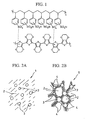
- FIG. 1 is an explanatory view showing schematically a molecular structure of a conductive poly(3,4-ethylenedioxythiophene)-poly(styrenesulfonic acid) (PEDOT/PSS).
- PEDOT/PSS conductive poly(3,4-ethylenedioxythiophene)-poly(styrenesulfonic acid)
- FIG. 2A is an explanatory view showing schematically a colloidal water dispersion of PEDOT/PSS.
- FIG. 2B is an explanatory view showing schematically a conductive polymer gel of the present invention obtained by adding a surfactant to the colloidal water dispersion of PEDOT/PSS shown in FIG. 2A , thereby to gelatinize the colloidal water dispersion.
- PEDOT/PSS molecules 3 are dispersed in water 2.
- a surfactant 4 is added to the colloidal water dispersion 1 of PEDOT/PSS and the mixture is left to stand under gelation conditions, as shown in FIG. 2B , a three-dimensional network is formed via the surfactant 4 and the mixture is easily gelatinized while containing water 2 to obtain a conductive polymer gel 5.
- a gel is obtained by adding alkylbenzenesulfonic acid as a surfactant, and optionally an alcohol to a colloidal water dispersion of PEDOT/PSS and leaving the mixture to stand under gelation conditions because a three-dimensional network is physically or chemically formed. It is believed that the resulting gel exhibits conductivity because of electrical conductivity and/or ionic conductivity. As a matter of course, it is not intended to limit this to such a way of thinking.
- gelation conditions are not specifically limited.
- a gel can be easily obtained, for example, by alkylbenzenesulfonic acid as a surfactant, and optionally an alcohol to a conductive conjugated polymer colloidal water dispersion under the conditions of an atmospheric atom and a normal temperature, well mixing them and leaving the mixture to stand at a predetermined temperature within a range from freezing temperature to the boiling temperature for a predetermined time.
- the temperature, at which gelation occurs to form a gel is not limited, but is preferably from 5 to 90oC, and more preferably 50oC or higher so as to obtain a solid gel having high conductivity and excellent handling properties.
- the temperature and time upon standing vary depending on the kind of the conductive conjugated polymer colloidal dispersion, and the kind, combination and amount of the surfactant and the alcohol. It is preferable to appropriately select the temperature and time, which enable gelation with good efficiency and production of satisfactory gel.
- the conductive conjugated polymer colloidal dispersion is obtained by dispersing at least one of (1) at least one of a conductive conjugated polymer selected from polyacetylene, polyphenylene, polypyrrole, polythiophene, polyfuran, polyselenophene, polyisothianaphthene, polyphenylene sulfide, polyaniline, polyphenylenevinylene, polythiophenevinylene, poly-perinaphthalene, polyanthracene, polynaphthalene, polypyrene, polyazulene, and derivatives thereof, and (2) conductive conjugated polymers doped with at least one dopant selected from iodine, arsenic fluoride, iron chloride, perchloric acid, sulfonic acid, perfluorosulfonic acid, polystyrenesulfonic acid, sulfuric acid, hydrochloric acid, nitric acid, and derivatives thereof, in a disperse medium (for example, water
- PEDOT/PSS poly(3,4-ethylenedioxythiophene)-poly(styrenesulfonic acid)
- a catalyst such as iron (III) toluenesulfonate
- the colloidal water dispersion is commercially available under the trade name of Baytron P (concentration of a conductive polymer (PEDOT/PSS): about 1.3% by weight, manufactured by Bayer Co.).
- the conductive conjugated polymer solution is obtained by dissolving the conductive conjugated polymer in water or an organic solvent.
- the conductive conjugated polymer colloidal dispersion and the conductive conjugated polymer solution can be used alone, or used in combination in arbitrary ratio.
- the surfactant used in the present invention is alkylbenzenesulfonic acid.
- Long-chain alkylbenzenesulfonic acid can be used, particularly preferably, because gelation efficiency is improved.
- the amount of the surfactant to be added in the conductive polymer gel is not specifically limited, but is preferably from 0.1 to 30 parts by weight, and more preferably from 0.5 to 10 parts by weight, based on 1 part by weight of the conductive polymer. When the amount is less than 0.1 parts by weight, gelation may not occur. On the other hand, when the amount exceeds 30 parts by weight, gelation may not occur, too.
- the alcohol is not specifically limited and there can be used at least one alcohol selected from known monohydric alcohols and polyhydric alcohols, and mixtures of two or more kinds of them.
- Examples of the monohydric alcohol include branched or linear alcohols, such as ethanol, isopropyl alcohol, and butanol; cyclic alcohol, polymer-like alcohol, and mixtures of two or more kinds of them.
- polyhydric alcohol examples include glycols such as ethylene glycol and propylene glycol; chain polyhydric alcohols such as glycerin, erythritol, xylytol, and sorbitol; cyclic polyhydric alcohols such as glucose and scroll; polymer-like polyhydric alcohols such as polyethylene glycol and polyvinyl alcohol; and mixtures of two or more kinds of them.
- isopropyl alcohol ethylene glycol and polyethylene glycol can be preferably used, and polyhydric alcohols such as ethylene glycol and polyethylene glycol are particularly preferable by the following reason.
- Ethylene glycol is used particularly preferably because it exerts an effect of causing gelation even at low concentration and also has no volatility.
- the molecular weight of polyethylene glycol is not specifically limited, but is preferably 1000 because gelation occurs even when the amount is smaller than that in case of the molecular weight of 400.
- the amount of the alcohol in the conductive polymer gel is not specifically limited, but is preferably from 1 to 70 parts by weight, and more preferably from 10 to 50 parts by weight, based on 1 part by weight of the conductive polymer. When the amount is less than 1 part by weight, gelation may not occur. The amount of more than 70 parts by weight is not preferable because viscosity of gel becomes too low and gelation may not occur, too.
- the surfactant can be used alone, or used in combination with an alcohol in arbitrary ratio. When using the surfactant in combination with the alcohol, the ratio thereof is not specifically limited.
- the first technique is a method of production in a conventional vial and its procedure will be described below.
- the second technique is a method of producing a film-like gel and its procedure will be described below.
- Electrical characteristics of the conductive polymer gel for example, conductivity and electromotive force can be determined by the following methods.
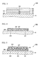
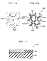
- FIG. 11 is a schematic sectional view showing an example of a toner 1001 according to an embodiment of the present invention.
- the toner 1001 comprises a generally spherical core portion 1011 made of a conductive polymer gel 1002, and a resin portion 1012 provided on the surface of the core portion 1011.
- the particle size of the toner 1001 is preferably 15 ⁇ m or less, and more preferably 8 ⁇ m or less. Consequently, excellent resolution can be realized and a pattern wiring having a fine line width can be formed when the toner 1001 is transferred and fixed onto a base material.
- the conductive polymer gel 1002 comprises water 1021, as a main component, a conductive conjugated polymer 1022, and a surfactant 1023 optionally an alcohol.
- the conductive polymer gel 1002 is formed by gelatinizing a conductive conjugated polymer 1022 using a surfactant 1023 optionally an alcohol, and those proposed in Japanese Patent Application No. 2003-19120 can be applied.
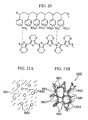
- FIG. 12 is a schematic view showing an example of a molecular structure of the conductive conjugated polymer 1022 shown in FIG. 13B .
- the conductive conjugated polymer 1022 is poly(3,4-ethylenedioxythiophene)-poly(styrenesulfonic acid)(hereinafter referred to as PEDOT/PSS) and is obtained by doping poly(3,4-ethylenedioxythiophene)(hereinafter referred to as PEDOT) with polystyrenesulfonic acid (hereinafter referred to as PSS) as a dopant.
- PEDOT/PSS poly(3,4-ethylenedioxythiophene)-poly(styrenesulfonic acid)
- PSS polystyrenesulfonic acid
- FIG. 13A is an explanatory view showing schematically a colloidal water dispersion of PEDOT/PSS
- FIG. 13B is an explanatory view showing schematically a conductive polymer gel 1002 of the present invention obtained by adding a surfactant 1023 to the colloidal water dispersion of PEDOT/PSS shown in FIG. 13A and gelatinizing the mixture.
- PEDOT/PSS molecules are dispersed in water 1021.
- the surfactant 1023 is added to the colloidal water dispersion of PEDOT/PSS and the mixture is left to stand under the gelation conditions, as shown in FIG. 13B , a three-dimensional network is formed via the surfactant 1023 and the mixture is easily gelatinized while including water 1021 therein, and thus a conductive polymer gel 1002 is obtained.
- a gel is obtained by adding the surfactant 1023 (optionally an alcohol) to the colloidal water dispersion of PEDOT/PSS and leaving the mixture to stand under gelation conditions because a three-dimensional network is physically or chemically formed. It is considered that the resulting gel exhibits conductivity because of electrical-conductivity and/or ionic conductivity. As a matter of course, this is not intended to be limited to such a way of thinking.
- the conductive conjugated polymer 1022 includes, for example, at least one selected from polyacetylene, polyphenylene, polypyrrole, polythiophene, polyfuran, polyselenophene, polyisothianaphthene, polyphenylene sulfide, polyaniline, polyphenylenevinylene, polythiophenevinylene, poly-perinaphthalene, polyanthracene, polynaphthalene, polypyrene, polyazulene, and derivatives thereof.
- polypyrrole or polythiophene shown in FIG. 12 is preferably used because it has high stability and high reliability and is readily available.
- the conductive conjugated polymer 1022 is preferably doped with a dopant, whereby, the concentration of a carrier in the conductive polymer gel 1002 increases and conductivity can be improved.
- the dopant includes, for example, at least one selected from iodine, arsenic fluoride, iron chloride, perchloric acid, sulfonic acid, perfluorosulfonic acid, polystyrenesulfonic acid, sulfuric acid, hydrochloric acid, nitric acid, and derivatives thereof.
- polystyrenesulfonic acid is preferable because high conductivity can be easily adjusted.
- Examples of the colloidal dispersion of the conductive conjugated polymer 1022 include a colloidal water dispersion of poly(3,4-ethylenedioxythiophene)-poly(styrenesulfonic acid) (hereinafter referred to as PEDOT/PSS) obtained by polymerizing 3,4-ethylenedioxythiophene in the presence of a catalyst such as iron (III) toluenesulfonate.
- PEDOT/PSS poly(3,4-ethylenedioxythiophene)-poly(styrenesulfonic acid)
- the colloidal water dispersion is commercially available under the trade name Baytron P (about 1.3 wt% dispersion of a conductive polymer (PEDOT/PSS), manufactured by Bayer Co.).
- the surfactant 1023 is alkylnaphthalenesulfonic acid.
- Long-chain alkylbenzenesulfonic acid is used, particularly preferably, because gelation efficiency is improved.
- the amount of the surfactant 1023 to be added to the conductive polymer gel is not specifically limited, but is preferably from 0.1 to 30 parts by weight, and more preferably from 0.5 to 10 parts by weight, based on 1 part by weight of the conductive polymer. When the amount is less than 0.1 parts by weight, gelation may not occur. The amount of more than 30 parts by weight is not preferable because gelation may not occur, too.
- the alcohol is not specifically limited and there can be used at least one alcohol selected from known monohydric alcohols and polyhydric alcohols, and mixtures of two or more kinds thereof.
- Examples of the monohydric alcohol include branched or linear alcohols, such as ethanol, isopropyl alcohol, and butanol; cyclic alcohol, polymer-like alcohol, and mixtures of two or more kinds thereof.
- polyhydric alcohol examples include glycols such as ethylene glycol and propylene glycol; chain polyhydric alcohols such as glycerin, erythritol, xylytol, and sorbitol; cyclic polyhydric alcohols such as glucose and scroll; polymer-like polyhydric alcohols such as polyethylene glycol and polyvinyl alcohol; and mixtures of two or more kinds therof.
- isopropyl alcohol ethylene glycol and polyethylene glycol can be preferably used, and polyhydric alcohols such as ethylene glycol and polyethylene glycol are particularly preferable for the following reason.
- Ethylene glycol is used particularly preferably because it exerts an effect of causing gelation even at low concentration and also has no volatility.
- the molecular weight of polyethylene glycol is not specifically limited, but is preferably 1000 because gelation occurs even when the amount is less than that in case of the molecular weight of 400.
- the amount of the alcohol in the conductive polymer gel 1002 is not specifically limited, but is preferably from 1 to 70 parts by weight, and more preferably from 10 to 50 parts by weight, based on 1 part by weight of the conductive polymer. When the amount is less than 1 part by weight, gelation may not occur. The amount of more than 70 parts by weight is not preferable because viscosity of gel becomes too small and gelation may not occur, too.
- the surfactant 1023 can be used alone, or used in combination with an alcohol in arbitrary ratio. When using the surfactant 1023 in combination with the alcohol, the ratio thereof is not specifically limited.
- the conductive conjugated polymer 1022 is gelatinized by using the surfactant 1023 optionally an alcohol by the following method.
- the surfactant 1023 optionally an alcohol as the additive are added by pouring into a colloidal dispersion prepared by dispersing the conductive conjugated polymer 1022 in water 1021 in a colloidal state and/or a conductive conjugated polymer solution without forming bubbles.
- the mixture is left to stand in an open or closed space in a conventional atmospheric atmosphere for a predetermined time in a state free from vibration.
- the conductive conjugated polymer solution is obtained by dissolving the conductive conjugated polymer 1022 in water or an organic solvent.
- the conductive conjugated polymer colloidal dispersion and the conductive conjugated polymer solution can be used alone, or can also be used in combination in arbitrary ratio.
- the core portion 1011 constituting the toner 1001 is composed of the conductive polymer gel 1002 and its shape is not specifically limited, but the core portion is in the form of particles.
- the amount of the conductive polymer gel 1002 constituting the core portion 1011 is preferably 40 parts by weight or more, and more preferably 65 parts by weight or more, based on 100 parts by weight of the toner 1001, and thus sufficient conductivity can be imparted to the base material when the toner 1001 is transferred onto the base material.
- the surface of the core portion 1011 is coated with the resin portion 1012.
- the resin portion 1012 is composed of an insulating resin, which serves as a binder, and there can be applied those which are used as a known binder for toner. Examples thereof include resins capable of fixing a toner by heat, such as styrene-acrylic copolymer resin, polyester resin, and epoxy resin; and resin mixtures obtained by adding a conductive polymer to the resins.
- the amount of the resin constituting the resin portion 1012 is preferably 0.1 parts by weight or more, and more preferably 30 parts by weight or less, based on 100 parts by weight of the toner 1001, and thus sufficient chargeability can be imparted to the surface of the toner 1001.
- an insulating portion made of various insulating components such as resin is provided, thereby to improve chargeability of the surface of the toner 1001 and to enhance developability.
- the surface of the toner 1001 is coated with a charge control agent 1013, thereby making it possible to adjust polarity (charge polarity) capable of charging the surface of the toner 1001 in the case of charging the toner 1001.
- charge control agent 1013 known charge control agents can be used and examples thereof include quaternary ammonium salt, azo-based metal-containing complex, salicylic acids metal complex, calixarenes, and amino group-containing fluorides. According to charge polarity of the surface of the toner 1001, the charge control agent can be appropriately selected and used.
- the amount of the charge control agent 1013 is preferably 0.1 parts by weight or more, and more preferably 5 parts by weight or less, based on 100 parts by weight of the toner 1001, and thus desired charge polarity can be imparted to the surface of the toner 1001.
- the surface of the toner 1001 is coated with a releasant 1014.
- a releasant 1014 known relesants can be used and examples thereof include olefinic wax and carnauba wax.
- the amount of the releasant 1014 is preferably 0.1 parts by weight or more, and more preferably 10 parts by weight or less, based on 100 parts by weight of the toner 1001, and thus sufficient releasability can be obtained.
- the toner 1001 can be produced by known methods such as grinding methods and particle precipitation methods.
- a conductive polymer gel 1002 is finely ground into particles, which serve as a core portion 1011, and finely ground particles of the conductive polymer gel 1002 are mixed with a resin, which serves as a resin portion 1012, and then the mixture is granulated to obtain a toner 1001 comprising the resin portion 1012 and the core portion 1011 whose surface is coated with the resin portion.
- the conductive polymer gel 1002, which constitutes the core portion 1011 of the toner 1001 is the same polymer compound (organic compound) as an insulating resin (binder) constituting the resin portion 1012, and is easily miscible and is also excellent in compatibility, and thus the entire surface of the core portion 1011 can be uniformly coated with the resin portion 1012.
- the entire surface of the core portion 1011 can be uniformly coated with the resin portion 1012, as described above, thus making it possible to realize a toner 1001 which is excellent in chargeability and can suppress poor development.
- the toner 1001 can be transferred and fixed onto the base material by a known developing system.
- the transfer method include toner image transfer methods such as electrostatic latent image transfer, electrostatic corona transfer, electrostatic belt transfer, electrostatic roller transfer, adhesion transfer, pressure transfer, and magnetic transfer methods.
- toner image transfer methods such as electrostatic latent image transfer, electrostatic corona transfer, electrostatic belt transfer, electrostatic roller transfer, adhesion transfer, pressure transfer, and magnetic transfer methods.
- multi-color or plural toners in combination there can be used multiple transfer systems such as multiple developing, transfer drum, intermediate transfer, and tandem systems.
- the core portion is composed of metal particles and true density is large, and therefore the development process requires a large charge amount.
- the core portion 1011 is made of a resin, like the toner for PPC (Plain Paper Copier), true density is small and the toner can be transferred and fixed onto the base material using a conventional copier.
- the first conductive functional member, the antistatic sheet 1003, and the first printed circuit member of the present invention will now be described.
- the first conductive functional member of the present invention comprises a sheet-like base material made of a resin film of PET (polyethylene terephthalate) or paper, and a conductive portion made of a toner provided on at least one surface of the base material.
- the conductive portion was formed by transferring and fixing the toner 1001 onto the base material. Detailed description of the toner 1001 is omitted because it is as described hereinabove.
- the base material is not limited to a sheet-like base material and may be any member on which the toner 1001 is transferred and fixed.
- the toner 1001 can be transferred and fixed onto the base material by a known developing system and a fine conductive portion can be formed with high accuracy.
- the shape of the conductive portion is not specifically limited and examples thereof include linear or planar conductive portion on which the toner 1001 is transferred and fixed onto at least one surface of the base material.
- the linear shape refers to a shape of one or plural straight lines or curved line, for example, pattern shape such as wavy shape, straight line, curved line, coil shape, polygon such as triangle or quadrangle, circle, ellipse, and shape, letter and symbol of a combination thereof.
- a planar conductive portion can be formed by forming plural linear conductive portions without pitches (intervals).
- planar conductive portion examples include a conductive portion whose one surface has a shape, for example, a polygon such as a triangle or quadrangle, circle, ellipse, and shape and symbol of a combination thereof.
- the conductive portion is not limited to those formed on the surface of the base material and may be those formed by transferring and fixing the toner 1001 inside the pore portion, recessed portion or groove provided on the base material.
- a conductive portion having a one-, two- or three-dimensional shape can be formed by using linear conductive portions alone or in combination.
- a conductive portion having a one-dimensional shape can be used as wiring and a conductive portion having a two-dimensional shape can be used as a pattern wiring, an electrode, an electromagnetic coil, and an antenna.
- a conductive portion having a three-dimensional shape can be used as a through electrode.
- Impedance characteristics and conductivity can be controlled by appropriately selecting the thickness, width, length and shape of the conductive portion, and the first conductive functional member can be used for various purposes which utilize the conductivity of the conductive portion.
- the first conductive functional member can be used as a wiring substrate and can be applied to various electronic equipment by mounting various electronic parts such as light emitting devices and IC chip on the base material. It can also be used as an IC tag and an IC label.
- FIG. 14 is a schematic sectional view showing an example of an antistatic sheet 1003 according to the present invention.
- the antistatic sheet 1003 is an example of the first conductive functional member and a conductive portion 1032 provided on a sheet-like base material 1031 has a planar shape.
- the conductive portion 1032 is provided on the entire surface of the base material 1031.
- the conductive portion 1032 imparts conductivity to the surface (surface of the base material 1031) of the antistatic sheet 1003 and the base material 1031 is not charged.
- the conductive portion 1032 may be provided on a portion of at least one surface of the base material 1031.
- the first printed circuit member of the present invention is an example of the first conductive functional member and the conductive portion provided on the sheet-like base material has a linear shape.
- the linear conductive portion can be used as a pattern wiring, an electrode, a through electrode, an electromagnetic coil, and an antenna. Therefore, the first printed circuit member can be used as a wiring substrate, an IC tag, and an IC label.
- a planar conductive portion can be formed by forming plural linear conductive portions without pitches (intervals), the conductive portion may be a planar conductive portion.
- the core portion 1011 of the toner 1001 is made of the conductive polymer gel 1002, the content of the metal component in the toner 1001 can be reduced as compared with the toner for formation of wiring of the prior art, wherein the core portion is made of metal particles. Consequently, it is made possible to reduce the environmental burden upon disposal of the printed circuit board or electronic parts made of the toner 1001.
- the antistatic sheet 1003, and the first printed circuit member since the conductive portion 1032 provided on at least one surface of the base material 1031 is composed of the toner 1001 of the present invention, the content of the metal component can be reduced and the environmental burden upon disposal can be reduced as compared with the toner for formation of wiring of the prior art, wherein the core portion is made of metal particles.
- the surface of the toner 1001 may be coated with an external additive so as to improve fluidity.
- an external additive known external additives can be used and examples thereof include fine inorganic particles such as silica, alumina, and titania (titanium oxide); and fine resin particles.
- the surface of the toner 1001 may be coated with coating agents such as silicone polymer and fluorine polymer; and carbon black.
- the toner 1001 is coated with a magnetic material.
- the toner may contain magnetic particles such as iron particles and ferrite particles, or a magnetic material such as magnetic particles whose surfaces are coated with a resin portion in the core portion 1011 or the resin portion 1012, or the toner may be a toner 1001 whose surfaces are coated with the magnetic material.
- the toner 1001 is mixed with a carrier.
- a powder of the toner 1001 may be mixed with a carrier powder.
- the carrier known carriers can be used and examples thereof include fine resin particles and magnetic powder.
- the particle size of the carrier is preferably 200 ⁇ m or less, and more preferably 100 ⁇ m or less. Consequently, it is made possible to achieve sufficient resolution.
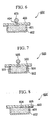
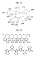
- FIG. 15 is a schematic view showing a conductive paste 2001 according to an embodiment of the present invention.
- the conductive paste 2001 contains at least a conductive polymer gel 2002, a conductive powder 2003, and a resin binder 2004.
- the conductive polymer gel 2002 and the conductive powder 2003 are conductive materials in the conductive paste 2001.
- the conductive polymer gel 2002 comprises water 2021, as a main component, the conductive conjugated polymer 2022, and the surfactant 2023 optionally an alcohol, as shown in FIG. 17B described hereinafter.
- the conductive polymer gel 2002 is formed by gelatinizing the conductive conjugated polymer 2022 by the surfactant 2023 optionally an alcohol and, for example, those proposed in the Japanese Patent Application No. 2003-19120 can be applied.
- FIG. 16 is a schematic view showing an example of a molecular structure of a conductive conjugated polymer 2022 shown in FIG. 17B .
- the conductive conjugated polymer 2022 is poly(3,4-ethylenedioxythiophene)-poly(styrenesulfonic acid) (hereinafter referred to as PEDOT/PSS) and is obtained by doping poly(3,4-ethylenedioxythiophene) (hereinafter referred to as PEDOT) with polystyrenesulfonic acid (hereinafter referred to as PSS) as a dopant.
- PEDOT/PSS poly(3,4-ethylenedioxythiophene)-poly(styrenesulfonic acid)
- PSS polystyrenesulfonic acid
- FIG. 17A is an explanatory view showing schematically PEDOT/PSS of a colloidal water dispersion
- FIG. 17B is an explanatory view showing schematically an example of a conductive polymer gel 2002 obtained by gelatinizing the colloidal water dispersion of PEDOT/PSS shown in FIG. 17A after the addition of a surfactant 2023.
- PEDOT/PSS molecules are dispersed in water.
- the surfactant 2023 is added to the colloidal water dispersion of PEDOT/PSS and the mixture is left to stand under the gelation conditions, as shown in FIG. 17B , a three-dimensional network is formed via the surfactant 2023 and the mixture is easily gelatinized while including water 2021 therein, and thus a conductive polymer gel 2002 is obtained.
- a gel is obtained by adding the surfactant 2023 optionally (an alcohol) to the colloidal water dispersion of PEDOT/PSS and leaving the mixture to stand under gelation conditions because a three-dimensional network is physically or chemically formed. It is considered that the resulting gel exhibits conductivity because of electronic conductivity and/or ionic conductivity. As a matter of course, this is not intended to be limited to such a way of thinking.
- the conductive conjugated polymer 2022 includes, for example, at least one selected from polyacetylene, polyphenylene, polypyrrole, polythiophene, polyfuran, polyselenophene, polyisothianaphthene, polyphenylene sulfide, polyaniline, polyphenylenevinylene, polythiophenevinylene, poly-perinaphthalene, polyanthracene, polynaphthalene, polypyrene, polyazulene, and derivatives thereof.
- polypyrrole or polythiophene shown in FIG. 16 is preferably used because it has high stability and high reliability and is easily available.
- the conductive conjugated polymer 2022 is preferably doped with a dopant, whereby, the concentration of a carrier in the conductive polymer gel 2002 increases and conductivity can be improved.
- the dopant includes, for example, at least one selected from iodine, arsenic fluoride, iron chloride, perchloric acid, sulfonic acid, perfluorosulfonic acid, polystyrenesulfonic acid, sulfuric acid, hydrochloric acid, nitric acid, and derivatives thereof.
- polystyrenesulfonic acid is preferable because high conductivity can be easily adjusted.
- colloidal dispersion of the conductive conjugated polymer 2022 examples include a colloidal water dispersion of poly(3,4-ethylenedioxythiophene)-poly(styrenesulfonic acid) (hereinafter referred to as PEDOT/PSS) obtained by polymerizing 3,4-ethylenedioxythiophene in the presence of a catalyst such as iron (III) toluenesulfonate.
- PEDOT/PSS poly(3,4-ethylenedioxythiophene)-poly(styrenesulfonic acid)
- the colloidal water dispersion is commercially available under the trade name of Baytron P (about 1.3 wt% dispersion of a conductive polymer (PEDOT/PSS), manufactured by Bayer Co.).
- the surfactant 2023 is alkylbenzenesulfonic acid.
- Long-chain alkylbenzenesulfonic acid is used, particularly preferably, because gelation efficiency is improved.
- the amount of the surfactant 2023 to be added to the conductive polymer gel is not specifically limited, but is preferably from 0.1 to 30 parts by weight, and more preferably from 0.5 to 10 parts by weight, based on 1 part by weight of the conductive polymer.
- gelation When the amount is less than 0.1 parts by weight, gelation may not occur. An amount of more than 30 parts by weight is not preferable because gelation may not occur, too.
- the alcohol is not specifically limited and there can be used at least one alcohol selected from known monohydric alcohols and polyhydric alcohols, and mixtures of two or more kinds thereof.
- Examples of the monohydric alcohol include branched or linear alcohols, such as ethanol, isopropyl alcohol, and butanol; cyclic alcohol, polymer-like alcohol, and mixtures of two or more kinds of them.
- polyhydric alcohol examples include glycols such as ethylene glycol and propylene glycol; chain polyhydric alcohols such as glycerin, erythritol, xylytol, and sorbitol; cyclic polyhydric alcohols such as glucose and scroll; polymer-like polyhydric alcohols such as polyethylene glycol and polyvinyl alcohol; and mixtures of two or more kinds of them.
- isopropyl alcohol ethylene glycol and polyethylene glycol can be preferably used, and polyhydric alcohols such as ethylene glycol and polyethylene glycol are particularly preferable for the following reason.
- Ethylene glycol is used particularly preferably because it exerts an effect of causing gelation even at low concentration and also has no volatility.
- the molecular weight of polyethylene glycol is not specifically limited, but is preferably 1000 because gelation occurs even when the amount is less than that in the case of the molecular weight of 400.
- the amount of the alcohol in the conductive polymer gel 2002 is not specifically limited, but is preferably from 1 to 70 parts by weight, and more preferably from 10 to 50 parts by weight, based on 1 part by weight of the conductive polymer. When the amount is less than 1 part by weight, gelation may not occur. An amount of more than 70 parts by weight is not preferable because viscosity of gel becomes too low and gelation may not occur, too.
- the surfactant 2023 can be used alone, or used in combination with an alcohol in arbitrary ratio.
- the ratio thereof is not specifically limited.
- the conductive conjugated polymer 2022 is gelatinized by using the surfactant 2023 and optionally an alcohol by the following method.
- the surfactant 2023 and optionally an alcohol as the additive are added by pouring into a colloidal dispersion prepared by dispersing the conductive conjugated polymer 2022 in water 2021 in a colloidal state and/or a conductive conjugated polymer solution without forming bubbles.
- the mixture is left to stand in an open or closed space in a conventional atmospheric atmosphere for a predetermined time in a state free from vibration.
- the conductive conjugated polymer solution is obtained by dissolving the conductive conjugated polymer 2022 in water or an organic solvent.
- the conductive conjugated polymer colloidal dispersion and the conductive conjugated polymer solution can be used alone, or can also be used in combination in arbitrary ratio.
- Examples of the conductive powder 2003 as a constituent component of the conductive paste 2001 include conductive carbon and metal powder.
- conductive carbon carbon black and acetylene carbon black produced by a furnace method and a channel methods can be used, and commercially available conduction grade conductive carbon can be preferably used.
- a silver powder is preferably used and imparts excellent conductivity.
- an alloy powder obtained by adding gold, platinum, palladium or rhodium to silver may be used.
- the conductive powder 2003 be previously subjected to a surface treatment, thereby to improve dispersibility of the conductive powder 2003. Consequently, the conductive powder 2003 is uniformly dispersed in the resin binder 2004, thereby making it possible to eliminate variation in characteristics such as conductivity.
- a treating agent of the conductive powder 2003 conventional surfactants and coupling agents can be used.
- Examples of the resin binder 2004 as the constituent component of the conductive paste 2001 include crosslinkable resins such as phenol resin, melamine resin, urea resin, xylene resin, alkyd resin, unsaturated polyester resin, acrylic resin, polyimide resin, furan resin, urethane resin, and polyisocyanate resin; and thermoplastic resins such as polyethylene, polypropylene, polyester, ABS resin, methyl polymethacrylate, polyvinyl chloride, polyvinylidene chloride, polyvinyl acetate, polyvinyl alcohol, polyacetal, polycarbonate, polyester, polyphenylene oxide, polysulfone, polyimide, polyether sulfone, polyallylate, polyether ketone, polyethylene tetrafluoride, and silicone resin.
- crosslinkable resins such as phenol resin, melamine resin, urea resin, xylene resin, alkyd resin, unsaturated polyester resin, acrylic resin, polyimide resin, furan resin, urethane
- crosslinking resins When using crosslinking resins, known curing agents and curing catalysts may be appropriately used.
- the solvent is usually added to the conductive paste 2001 so as to adjust the viscosity
- the resulting solution can be applied to the base material such as resin film or substrate by a conventional printing technique.
- solvent known solvents can be used.
- a solvent having a boiling point of 250oC or lower can be preferably used because the solvent is nearly vaporized without leaving a residue when the conductive paste 2001 is cured by heating.
- the solvent examples include hydrocarbon solvents such as toluene, cyclohexane, methylcyclohexane, n-hexane, and pentane; alcohols such as isopropyl alcohol and butylalcohol; ketones such as cyclohexanone, methyl ethyl ketone, methyl isobutyl ketone, diethyl ketone, and isophorone; esters such as ethyl acetate, propyl acetate, and butyl acetate; glycol monoethers such as ethylene glycol monomethyl ether, propylene glycol monoethyl ether, diethylene glycol monomethyl ether, and 3-methoxy-3-methylbutyl acetate, and acetates thereof; and mixtures of one or more kinds thereof.
- hydrocarbon solvents such as toluene, cyclohexane, methylcyclohexane, n-hexane, and pentan
- the conductive paste 2001 can be cured by heating after applying to the base material.
- a heating means a heating means using a heater is used alone, or in combination with a means of applying infrared light or high frequency.
- the conductive paste 2001 can be cured by irradiating with an electromagnetic wave such as microwaves, infrared light, visible light, ultraviolet light, vacuum ultraviolet light, X-rays, or electron beams after being applied to the base material.
- an electromagnetic wave such as microwaves, infrared light, visible light, ultraviolet light, vacuum ultraviolet light, X-rays, or electron beams after being applied to the base material.
- the conductive paste 2001 can be cured to form wiring.
- the conductive paste 2001 is produced by mixing constituent components such as conductive polymer gel 2002, conductive powder 2003 and resin binder 2004 using a known stirrer.
- a stirrer such as a homogenizer
- a kneading machine such as a triple roller or a kneader
- the constituent components may be mixed while applying ultrasonic waves or high frequency, or mixed while applying a pressure in a stirrer or kneading machine and varying the applied pressure.
- the conductive paste 2001 contains the conductive powder 2003 such as metal powder, and the conductive polymer gel 2002 as the conductive material, the content of the conductive powder 2003 required to obtain sufficient conductivity can be reduced as compared with the prior art. Since the content of the metal component (conductive powder 2003) can be reduced as compared with the prior art, the environmental burden can be reduced upon disposal of the printed circuit board and electronic parts which employ the conductive paste 2001.
- a ratio of the sum total of the content (G) in the conductive polymer gel 2002 and the content of a carbon component (Cp) in the conductive powder 2003 (G + Cp) to the sum total of the content (G) of the conductive polymer gel 2002 in the conductive paste 2001 and the content (P) of the conductive powder 2003 (G + P), ((G + Cp)/(G + P)), is preferably 0.07 or more, more preferably from 0.13 to 0.24, and most preferably 0.5 or more.
- the ratio (G + Cp)/(G + P) represents the proportion of an organic compound component such as carbon other than the metal component among the conductive materials, and the environmental burden can be reduced by controlling the proportion to 0.07 or more.
- a ratio of the sum total of the content (G) of the conductive polymer gel 2002 and the content (P) of the conductive powder 2003 (P + G) to the content B of the resin binder 2004, ((G + P)/B), is preferably from 3/7 to 9/1, and more preferably from 4 to 6.
- the ratio (G + P)/B represents a ratio of the conductive material to the resin binder 2004.
- the ratio (G + P)/B is 3/7 or more, conductivity required of the conductive paste 2001 is achieved and wirings and electrodes having sufficient conductivity can be formed by using the conductive paste 2001, and also bonding of terminals and lead wires of electronic parts can be conducted.
- the conductive powder 2003 is generally made of an inorganic compound such as metal powder and is inferior in compatibility with a resin binder (organic compound) 2004. Therefore, when the content of the conductive powder 2003 in the conductive paste 2001 is large and the content of the resin binder 2004, like the prior art, the conductive powder 2003 is hardly miscible with the resin binder 2004, thereby causing phase separation, and thus integrity of the conductive paste 2001 to the base material and flexibility drastically deteriorate. Therefore, in the case in which wiring is formed by applying the conductive paste 2001 to the base material and curing the conductive paste, the wiring is peeled off from the base material. Also because of poor flexibility, when the base material is bent, the wiring is broken at the bending portion of the base material.
- the conductive polymer gel 2002 is a polymer, like the resin binder 2004, molecules thereof are entangled with the surface of the conductive powder 2003, thereby retaining the conductive powder 2003.
- the conductive polymer gel 2002 serves as a conductive material, the content of the conductive powder 2003 can be reduced by the amount of the conductive polymer gel 2002.
- the content of the metal component (conductive powder 2003) is small as compared with the prior art, the environmental burden can be reduced upon disposal of the printed circuit board.
- the conductive polymer gel 2002 is the same polymer compound (organic compound) as the resin binder 2004, and is easily miscible and is also excellent in compatibility. Therefore, the conductive polymer gel 2002 and the resin binder 2004 can be uniformly mixed to easily obtain a conductive paste 2001.
- the conductive paste 2001 does not contain the conductive powder 2003 and may be composed of the conductive polymer gel 2002 and the resin binder 2004. Since conductivity is imparted even if the conductive material in the conductive paste 2001 is only the conductive polymer gel 2002, pattern wiring can be formed by applying the conductive paste 2001 to the base material and curing the conductive paste with heating.
- the conductive paste 2001 may contain fillers such as silica, alumina, mica, and carbon powder; colorants such as pigments and dyes: and auxiliaries such as polymerization inhibitors, antioxidants, thickeners, thixotropic agents, suspending agents, and dispersants.
- fillers such as silica, alumina, mica, and carbon powder
- colorants such as pigments and dyes
- auxiliaries such as polymerization inhibitors, antioxidants, thickeners, thixotropic agents, suspending agents, and dispersants.
- Each content of the fillers, colorants and auxiliaries is preferably 35% by weight or less based on the sum total of the conductive polymer gel 2002, the conductive powder 2003 and the resin binder 2004. Consequently, the above operation and effect of the present invention is not adversely affected [Second conductive functional member, second printed circuit member]
- the second conductive functional member of the present invention comprises a sheet-like base material made of a resin film of PET (polyethylene terephthalate) or paper, and a conductive portion made of a conductive paste provided on at least one surface of the base material.
- the conductive portion was formed by transferring and fixing the conductive paste 2001 onto the base material. Detailed description of the conductive paste 2001 is omitted because it is as described hereinabove.
- the method for formation of the conductive portion includes, for example, a method of applying the conductive paste 2001 of the present invention on the base material to form a predetermined pattern by a known printing technique such as screen printing, and curing while heating or irradiating with electromagnetic waves such as light.
- the base material is not limited to a sheet-like base material and may be any member on which the conductive paste 2001 can be applied and cured.
- the conductive paste 2001 can be applied and cured on the base material by a known printing technique and a fine conductive portion can be formed with high accuracy.
- the shape of the conductive portion is not specifically limited and examples thereof include linear or planar conductive paste 2001 which is applied and cured on at least one surface of the base material.
- the linear shape refers to a shape of one or plural straight lines or curved line, for example, pattern shape such as wavy shape, straight line, curved line, coil shape, polygon such as triangle or quadrangle, circle, ellipse, and shape, letter and symbol of a combination thereof.
- a planar conductive portion can be formed by forming plural linear conductive portions without pitches (intervals).
- planar conductive portion examples include a conductive portion whose one surface has a shape, for example, polygon such as triangle or quadrangle, circle, ellipse, and shape and symbol of a combination thereof.
- the conductive portion is not limited to those formed on the surface of the base material and may be those formed by applying and curing the conductive paste 2001 inside the pore portion, recessed portion or groove provided on the base material.
- a conductive portion having a one-, two- or three-dimensional shape can be formed by using linear conductive portions alone or in combination.
- a conductive portion having a one-dimensional shape can be used as wiring and a conductive portion having a two-dimensional shape can be used as a pattern wiring, an electrode, an electromagnetic coil, and an antenna.
- a conductive portion having a three-dimensional shape can be used as a through electrode.
- Impedance characteristics and conductivity can be controlled by appropriately selecting the thickness, width, length and shape of the conductive portion, and the second conductive functional member can be used for various purposes which utilize the conductivity of the conductive portion.
- the second conductive functional member can be used as a wiring substrate and can be applied to various electronic equipments by mounting various electronic parts such as light emitting devices and IC chip on the base material. It can also be used as an IC tag and an IC label.
- the conductive paste 2001 contains the conductive polymer gel 2002 and the conductive polymer gel 2002 is the same polymer compound (organic compound) as an resin binder 2004, and is easily miscible and is also excellent in compatibility, and thus the conductive polymer gel 2002 and the resin binder 2004 are uniformly mixed to obtain a conductive paste 2001.
- the conductive paste 2001 obtained by uniformly mixing the constituent components has a nearly constant viscosity, and thus pattern wiring having uniform thickness and uniform line width can be easily formed with good accuracy when the conductive paste 2001 is applied to the base material. Therefore, it is made possible to realize the second conductive functional member having a conductive portion, which has less variation in electrical characteristics such as impedance characteristics.
- the conductive portion formed by curing the conductive paste 2001 is excellent in integrity with the base material and is less likely to be peeled off. Also, because of excellent flexibility, the conductive portion is less likely to be broken at the bending portion of the base material when the base material is bent.
- the second printed circuit member of the present invention is an example of the second conductive functional member, and the conductive portion provided on the sheet-like base material has a linear form.
- the linear conductive portion is used as a pattern wiring, an electrode, a through electrode, an electromagnetic coil, and an antenna. Therefore, the second printed circuit member can be used as a wiring substrate, an IC tag, and an IC label.
- the conductive portion formed by curing the conductive paste 2001 is excellent in flexibility, even in the case in which a second printed circuit board comprising a base material composed of a flexible resin sheet made of PET abase material, which is used by bending the base material, like a membrane circuit board of a keyboard, wiring is less likely to be broken at the bending portion of the base material. Therefore, it can be preferably used.
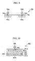
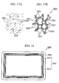
- FIG. 18 is a plan view showing a non-contact type IC media as an example of the second printed circuit member.
- the non-contact type IC media (hereinafter expressed by the same reference symbol 2005 as that of the second printed circuit member) comprises a base material 2006 made of a resin film of PET (polyethylene terephthalate) or a paper, and an RF-ID module 2007 (RF-ID: Radio Frequency-Identification) provided on the base material 2006.
- a base material 2006 made of a resin film of PET (polyethylene terephthalate) or a paper
- RF-ID module 2007 RF-ID: Radio Frequency-Identification
- the RF-ID module 2007 comprises an antenna coil 2071 composed of pattern wiring (linear conductive portion) formed by winding once or plural times in the form of a planar coil on the base material 2006, and an IC chip 2072 connected to the antenna coil 2071.
- the pattern wiring (conductive portion), which serves as the antenna coil 2071, is formed by applying the conductive paste 2001 to the base material 2006 and curing the conductive paste.
- the method for formation of the antenna coil 2071 includes, for example, a method of applying the conductive paste 2001 of the present invention on the base material 2006 to form a predetermined pattern, which serves as the antenna coil 2071, by a known printing technique such as screen printing, and curing while heating or irradiating with electromagnetic waves such as light.
- Radio communication can be conducted by the antenna coil 2071.
- received data are stored in the IC chip 2072 and also data stored in the IC chip 2072 can be transmitted to a receiver of an external reader/writer.
- the antenna coil 2071 is not limited to an antenna coil composed of a linear conductive portion having a two-dimensional shape such as planar coil shown in FIG. 18 , and may be an antenna coil composed of a linear conductive portion having a three-dimensional shape such as a spiral formed inside a through hole provided on the base material 2006 and both surfaces of the base material 2006.
- the antenna is not limited to a coil-shaped antenna such as antenna coil 2071 and may be any antenna composed of a linear conductive portion having a shape capable of receiving and transmitting an electric wave having a predetermined frequency.
- Examples thereof include a bipolar antenna composed of a linear conductive portion having a one-dimensional shape such as linear shape or a plygonal shape such as a triangle, and an antenna composed of a planar conductive portion formed by forming plural linear conductive portions without pitches (intervals).
- non-contact type IC media 2005 examples include a non-contact type IC tag 5 comprising a sheet-like base material 2006 such as a card, label, postcard, or envelope and an RF-ID module 2007 provided on the base material, and those comprising a base material 2006 such as an IC label or corrugated board, and an RF-ID module 2007 provided on at least one surface of the base material.
- a fuel cell comprises a power generation portion composed of one or more cells stacked with each other, each cell (single cell or unit cell) comprising at least a first electrode (hereinafter referred to as a fuel electrode), a second electrode (hereinafter referred to as an air electrode) and an electrolyte interposed between the electrodes.
- a fuel electrode hereinafter referred to as a fuel electrode
- a second electrode hereinafter referred to as an air electrode
- the power generation portion is provided with a gas feeding mechanism, which feeds a hydrogen gas to a fuel electrode and feeds an oxygen gas to an air electrode, and a connection portion which is electrically connected to the fuel electrode and the air electrode and connects a power generation portion to an external circuit board.
- FIG. 19 is a schematic view showing a fuel cell 3001 according to an embodiment of the present invention.
- the fuel cell is a polymer electrolyte type fuel cell (hereinafter also referred to as PEFC) and the cell 3001 comprises a polymer electrolyte film 3002, a fuel electrode (negative electrode) 3031 provided at both sides of the polymer electrolyte film 3002, and an air electrode (positive electrode) 3032.
- PEFC polymer electrolyte type fuel cell
- each side facing outside (the other principal plane opposite to one principal plane contacted with the polymer electrolyte film 3002, among two principal planes) is provided with a separator (pass partition plate) 3004 and the polymer electrolyte film 3002, the fuel electrode 3031 and the air electrode 3032 are interposed between a pair of separators 3004.
- a hydrogen gas is fed between a separator 3041 and a fuel electrode 3031 at the fuel electrode side, while an oxygen gas is fed between a separator 3042 and an air electrode 3032 at the air electrode side.
- a groove (not shown), which serves as a passage of a gas, is provided on the surface of the separator 3004.
- the polymer electrolyte film 3002 is a proton-conductive solid polymer film and examples thereof include proton-conductive ion exchange films such as perfluorosulfonic acid film (manufactured by Dupont under the trade name of Nafion).
- the fuel electrode 3031 and the air electrode 3032 comprises a conductive polymer gel 3005 containing water 3051, as a main component, a conductive conjugated polymer 3052, and a surfactant 3053 and optionally an alcohol.
- the conductive polymer gel 3005 is formed by gelatinizing the conductive conjugated polymer 3052 by the surfactant 3053 and optionally alcohol, and those proposed in Japanese Patent Application No. 2003-19120 can be applied.
- the conductive polymer gel 3005 is a gel having conductivity and also has properties which are different from those of a fluid which has high viscosity but flows. Also the conductive polymer gel has a proper strength and can retain its shape, and is also used as an electrode 3003 after being formed into a sheet-like material or a thin film.
- only one electrode 3003 may be composed of the conductive polymer gel 3005.
- FIG. 20 is a schematic view showing an example of a molecular structure of the conductive conjugated polymer 3005 shown in FIG. 21B .
- the conductive conjugated polymer 3052 is poly(3,4-ethylenedioxythiophene)-poly(styrenesulfonic acid)(hereinafter referred to as PEDOT/PSS) and is obtained by doping poly(3,4-ethylenedioxythiophene)(hereinafter referred to as PEDOT) with polystyrenesulfonic acid (hereinafter referred to as PSS) as a dopant.
- PEDOT/PSS poly(3,4-ethylenedioxythiophene)-poly(styrenesulfonic acid)
- PSS polystyrenesulfonic acid
- FIG. 21A is an explanatory view showing schematically a colloidal water dispersion of PEDOT/PSS
- FIG. 21B is an explanatory view showing schematically a conductive polymer gel 3005 of the present invention obtained by adding a surfactant 3053 to the colloidal water dispersion of PEDOT/PSS shown in FIG. 21A and gelatinizing the mixture.
- PEDOT/PSS molecules are dispersed in water 3051.
- the surfactant 3053 is added to the colloidal water dispersion of PEDOT/PSS and the mixture is left to stand under the gelation conditions, as shown in FIG. 21B , a three-dimensional network is formed via the surfactant 3053 and is easily gelatinized while including water 3051 therein, and thus a conductive polymer gel 3005 is obtained.
- a gel is obtained by adding the surfactant 3053 (optionally an alcohol) to the colloidal water dispersion of PEDOT/PSS and leaving the mixture to stand under gelation conditions because a three-dimensional network is physically or chemically formed. It is believed that the resulting gel exhibits conductivity because of electronic conductivity and/or ionic conductivity. As a matter of course, this is not intended to be limited to such a way of thinking.
- the conductive conjugated polymer 3052 includes, for example, at least one selected from polyacetylene, polyphenylene, polypyrrole, polythiophene, polyfuran, polyselenophene, polyisothianaphthene, polyphenylene sulfide, polyaniline, polyphenylenevinylene, polythiophenevinylene, poly-perinaphthalene, polyanthracene, polynaphthalene, polypyrene, polyazulene, and derivatives thereof.
- polypyrrole or polythiophene shown in FIG. 20 is preferably used because it has high stability and high reliability and is readily available.
- the conductive conjugated polymer 3052 is preferably doped with a dopant, whereby, the concentration of a carrier in the conductive polymer gel 3005 increases and conductivity can be improved.
- the dopant includes, for example, at least one selected from iodine, arsenic fluoride, iron chloride, perchloric acid, sulfonic acid, perfluorosulfonic acid, polystyrenesulfonic acid, sulfuric acid, hydrochloric acid, nitric acid, and derivatives thereof.
- polystyrenesulfonic acid is preferable because high conductivity can be easily adjusted.
- colloidal dispersion of the conductive conjugated polymer 3052 examples include a colloidal water dispersion of poly(3,4-ethylenedioxythiophene)-poly(styrenesulfonic acid) (hereinafter referred to as PEDOT/PSS) obtained by polymerizing 3,4-ethylenedioxythiophene in the presence of a catalyst such as iron (III) toluenesulfonate.
- PEDOT/PSS poly(3,4-ethylenedioxythiophene)-poly(styrenesulfonic acid)
- the colloidal water dispersion is commercially available under the trade name Baytron P (about 1.3 wt% dispersion of a conductive polymer (PEDOT/PSS), manufactured by Bayer Co.).
- the surfactant 3053 is alkylbenzenesulfonic acid
- long-chain alkylbenzenesulfonic acid is used, particularly preferably, because gelation efficiency is improved.
- the amount of the surfactant 3053 to be added to the conductive polymer gel 3005 is not specifically limited, but is preferably from 0.1 to 30 parts by weight, and more preferably from 0.5 to 10 parts by weight, based on 1 part by weight of the conductive polymer. When the amount is less than 0.1 parts by weight, gelation may not occur. The amount of more than 30 parts by weight is not preferable because gelation may not occur, too.
- the alcohol is not specifically limited and there can be used at least one alcohol selected from known monohydric alcohols and polyhydric alcohols, and mixtures of two or more kinds thereof.
- Examples of the monohydric alcohol include branched or linear alcohols, such as ethanol, isopropyl alcohol, and butanol; cyclic alcohol, polymer-like alcohol, and mixtures of two or more kinds thereof.
- polyhydric alcohol examples include glycols such as ethylene glycol and propylene glycol; chain polyhydric alcohols such as glycerin, erythritol, xylytol, and sorbitol; cyclic polyhydric alcohols such as glucose and scroll; polymer-like polyhydric alcohols such as polyethylene glycol and polyvinyl alcohol; and mixtures of two or more kinds thereof.
- isopropyl alcohol ethylene glycol and polyethylene glycol can be preferably used, and polyhydric alcohols such as ethylene glycol and polyethylene glycol are particularly preferable by the following reason.
- Ethylene glycol is used particularly preferably because it exerts an effect of causing gelation even at low concentration and also has no volatility.
- the molecular weight of polyethylene glycol is not specifically limited, but is preferably 1000 because gelation occurs even when the amount is less than that in case of the molecular weight of 400.
- the amount of the alcohol in the conductive polymer gel 3005 is not specifically limited, but is preferably from 1 to 70 parts by weight, and more preferably from 10 to 50 parts by weight, based on 1 part by weight of the conductive polymer. When the amount is less than 1 part by weight, gelation may not occur. An amount of more than 70 parts by weight is not preferable because viscosity of gel becomes too low and gelation may not occur, too.
- the surfactant 3053 can be used alone, or be used in combination with an alcohol in arbitrary ratio.
- the ratio thereof is not specifically limited.
- the conductive conjugated polymer 3052 is gelatinized by using the surfactant 3053 and optionally an alcohol by the following method.
- the surfactant 3053 and optionally an alcohol as the additive are added by pouring into a colloidal dispersion prepared by dispersing the conductive conjugated polymer 3052 in water 3051 in a colloidal state and/or a conductive conjugated polymer solution without forming bubbles.
- the mixture is left to stand in an open or closed space in a conventional atmospheric atmosphere for a predetermined time in a state free from vibration.
- the conductive conjugated polymer 3052 solution is obtained by dissolving the conductive conjugated polymer 3052 in water or an organic solvent.
- the conductive conjugated polymer colloidal dispersion and the conductive conjugated polymer solution can be used alone, or can also be used in combination in arbitrary ratio.
- the method of forming the fuel electrode 3031 and the air electrode 3032 by using the conductive polymer gel 3005 includes, for example, a method of forming the conductive polymer gel 3005 into a sheet having a predetermined thickness by the method described above, and providing the sheet at both ends of a polymer electrolyte film 3002 to form the fuel electrode 3031 and the air electrode 3032.
- the hydrogen gas fed is dissolved and incorporated into water 3051 included in the conductive polymer gel 3005.
- Hydrogen (molecules) dissolved in water 3051 of the conductive polymer gel 3005 is electrolytically dissociated to produce hydrogen ions and electrons according to the scheme (X).
- Electrons produced by dissociation of hydrogen propagate through the conductive conjugated polymer 3052 in the conductive polymer gel 3005 and flow through an external circuit board (not shown) connected to the cell 3001 to reach the air electrode 3032 of the cell 3001.
- Hydrogen ions produced by dissociation of hydrogen move in water 3051 included in the conductive polymer gel 3005 toward the polymer electrolyte film 3002. Hydrogen ions move in the polymer electrolyte film 3002 toward the air electrode 3032, together with water.
- the oxygen gas fed is dissolved and incorporated into water 3051 included in the conductive polymer gel 3005.
- Electrons produced in the fuel electrode 3031 flow through an external circuit board (not shown) from the fuel electrode 3031 to the air electrode 3032 of the cell 3001, and propagate through the conductive conjugated polymer 3052 in the conductive polymer gel 3005. Hydrogen ions move in water 3051 of the conductive polymer gel 3005.
- the fuel electrode 3031 comprises at least the conductive polymer gel 3005, it is made possible to dissociate the hydrogen gas into hydrogen ions and electrons by dissolving in water 3051 included in the conductive polymer gel 3005. Therefore, it is not necessary to dissociate the hydrogen gas into hydrogen ions by using a catalyst layer made of platinum or a platinum alloy, like in the prior art.
- the air electrode 3032 cntains at least the conductive polymer gel 3005 it is made possible to dissolve and incorporate the oxygen gas into water 3051 included in the conductive polymer gel 3005. Therefore, it is not necessary to adsorb the oxygen gas using a catalyst layer made of platinium or a platinum alloy, like in the prior art.
- the conductive polymer gel 3005 has proper strength and also has conductivity, it is not necessary that the fuel electrode 3031 and the air electrode 3032 have a two-layered structure of a supporting layer and a catalyst layer, like in the prior art, and the electrodes can be formed only of the conductive polymer gel 3005.
- the power generation portion of the cell has a stacked structure obtained by stacking plural cells 3001, thereby achieving high electromotive force. Therefore, when the thickness of the fuel electrode 3031 and the air electrode 3032 of the cell 3001 can be reduced, the thickness of the power generation portion is markedly reduced, thus making it possible to reduce the thickness and size of the fuel cell.
- the thickness of the thin film of the conductive polymer gel 3005, which constitutes the electrode 3003, is preferably from 0.01 to 50 ⁇ m, and thus the thin film of the conductive polymer gel 3005 has proper strength and can retain the shape. Therefore, it is made possible to ensure sufficient contact area between the hydrogen gas or oxygen gas and water 3051 included in the conductive polymer gel 3005, and to dissolve and incorporate the hydrogen gas or oxygen into water 3051.
- the electrode 3003 is made of the conductive polymer gel 3005, a problem such as separation of two layers does not occur, like the two-layered structure of the catalyst layer and the supporting layer of the prior art, and excellent long-term stability can be achieved.
- a discharge voltage and a current value are not decreased by an influence of carbon monoxide and approximately fixed voltage and current values can be stably obtained.
- the oxidation reaction in the fuel electrode 3031 and the reductive reaction in the air electrode 3032 can be conducted at a high reaction rate, whereby, power loss of the cell 3001 can be reduced and high discharge voltage (electromotive force) can be achieved.
- Examples 1 to 4 and Comparative Examples 1 to 2 describe the case where gelation is conducted by standing in an open state after the addition of a surfactant.
- a conductive conjugated polymer colloidal dispersion PEDOT/PSS (about 1.3 wt% colloidal water dispersion of a conductive polymer (PEDOT/PSS) manufactured by Bayer Co. under the trade name Baytron P) was mixed with 0.7 parts by weight of dodecylbenzenesulfonic acid (C 12 H 25 C 6 H 4 SO 3 H) (hereinafter also referred to as DBS) as an additive and, after stirring for about 10 minutes, the mixture was left to stand at a standing temperature of 10oC, 25oC and 50oC in a closed state for one day to obtain samples gelatinized at different standing temperatures.
- DBS dodecylbenzenesulfonic acid
- the gelation degree was examined.
- the gelation degree was evaluated by the following three-rank criteria (represented by the symbols ⁇ , ⁇ and ⁇ ).
- Example 2 the operation was conducted in the same manner as in Example 1, except that the amount of DBS to be mixed as the additive was changed to 1.0 part by weight, and then the mixture was left to stand at a standing temperature of 10oC, 25oC and 50oC in a closed state for one day to obtain samples gelatinized at different standing temperatures.
- Example 2 the operation was conducted in the same manner as in Example 1, except that the amount of DBS to be mixed as the additive was changed to 2.0 parts by weight, and then the mixture was left to stand at a standing temperature of 10oC, 25QC and 50QC in a closed state for one day to obtain samples gelatinized at different standing temperatures.
- Example 2 the operation was conducted in the same manner as in Example 1, except that the amount of DBS to be mixed as the additive was changed to 10 parts by weight, and then the mixture was left to stand at a standing temperature of 10oC, 25oC and 50oC in a closed state for one day to obtain samples gelatinized at different standing temperatures.
- Example 2 the operation was conducted in the same manner as in Example 1, except that the amount of DBS to be mixed as the additive was changed to 0.5 parts by weight, and then the mixture was left to stand at a standing temperature of 10oC, 25oC and 50oC in a closed state for one day to obtain samples gelatinized at different standing temperatures.
- Example 1 Additive (parts by weight) Evaluation results of gelation degree Measurement results of conductivity (mS/cm) Standing temperature (oC) DBS 10 25 50
- Example 1 0.7 ⁇ ⁇ ⁇ 0.5
- Example 2 1.0 ⁇ ⁇ ⁇ 1.5
- Example 3 2.0 ⁇ ⁇ ⁇ 20
- Example 4 10.0 ⁇ ⁇ ⁇ 98 Comparative Example 1 0.0 ⁇ ⁇ ⁇ * Comparative Example 2 0.5 ⁇ ⁇ ⁇ -
- This example describes the case where a surfactant such as DBS is used as the additive and the amount thereof is 2 parts by weight and also an electrolyte is added.
- a surfactant such as DBS
- the amount thereof is 2 parts by weight and also an electrolyte is added.
- the operation was conducted in the same manner as in Example 13, except that TFMS-Li was used as the electrolyte and the amount thereof was adjusted to 5 parts by weight, and then the mixture was left to stand at a standing temperature of 10oC, 25oC and 50oC in an open state to obtain samples gelatinized at different standing temperatures.
- Example 15 the operation was conducted in the same manner as in Example 15, except that TFMS-Ag was used as the electrolyte in place of TFMS-Li and the amount thereof was changed to 5 parts by weight, and then the mixture was left to stand at a standing temperature of 10oC, 25oC and 50oC to obtain samples gelatinized at different standing temperatures.
- This example describes an embodiment wherein the above conductive polymer gel, for example, the gel obtained in Example 3 is applied to an iontophoretic patch label for local delivery of a treating agent with reference to FIG. 3 to FIG. 5 .
- FIG. 3 is a schematic sectional view showing an example of an iontophoretic patch label for local delivery of a treating agent according to the present invention.
- FIG. 4 and FIG. 5 are schematic sectional views each showing another example of an iontophoretic patch label for showing local delivery of a treating agent according to the present invention.
- Any iontophoretic patch label for local delivery of a treating agent shown in FIG. 3 to FIG. 5 is an iontophoretic patch label comprising a pad, and electrodes composed of an anode and a cathode provided on one surface of the pad at regular intervals, which locally delivers a treating agent to an analyte by contacting the other surface on the pad with the analyte and applying an electric current between the electrodes.
- the pad is made of a conductive polymer gel containing water, as a main component, a conductive conjugated polymer alkylbenzenesulfonic acid and optionally an alcohol.
- the iontophoretic patch label 100 for local delivery of a treating agent shown in FIG. 3 comprises an electrode 101 which serves as an anode, and another electrode 102 which serves as a cathode, and a pad 103 made of the conductive polymer gel of the present invention disposed so as to stretch over both electrodes. Between the electrodes, an insulating material 104 prevents the electrodes from contacting each other, and a power supply 105 is connected to the electrodes.
- the iontophoretic patch label 100 for local delivery of a treating agent comprises a sheet-like base material 106 such as paper or plastic, and these parts stacked on the base material at each predetermined position.
- the treating agent (not shown, for example, chemical, cosmetic, etc.) is previously prepared on the surface of an analyte 10 such as skin, and the treating agent is ionized by applying a weak electric current between the electrodes 101 and 102 from the power supply 105, thereby to permeate into the local tissue through the analyte 10, and thus the treating agent can be efficiently delivered.
- the reference symbol whose two lower figures are the same as those in the reference symbol in FIG. 3 , denotes the same component part.
- the iontophoretic patch label 200 for local delivery of a treating agent shown in FIG. 4 is different from the iontophoretic patch label 100 for local delivery of a treating agent shown in FIG. 3 in that the treating agent 207 is previously contained in the pad 203 made of the conductive polymer gel.
- the treating agent 207 is previously contained in the pad 203 in the iontophoretic patch label 200 for local delivery of a treating agent, it is excellent in handling properties or convenience during use because it is not necessary to previously apply the treating agent on the surface of the analyte 10.
- the iontophoretic patch label 300 for local delivery of a treating agent shown in FIG. 5 is different from the iontophoretic patch label 100 for local delivery of a treating agent shown in FIG. 3 in that a case-shaped base material 308 made of plastic comprises numerous of fine pores 309 provided thereon and a container 310 containing a treating agent 307 is disposed on the base material 308.
- the treating agent 307 contained in the container 310 is fed through a hole 309 toward the gel 303 filled in the base material 308 in the direction shown by the arrow.
- the treating agent may be forcibly fed by an external power supply (not-shown) or naturally fed by gravity or an adsorption power.
- Such a feeding system makes it possible to deliver the treating agent to the surface of the analyte 10, and thus a preferable patch label can be provided for a long period.
- This example describes an embodiment wherein the above conductive polymer gel, for example, the gel obtained in Example 3 is applied to a biomedical electrode with reference to FIG. 6 to FIG. 10 .
- FIG. 6 is a schematic sectional view showing an example of a biomedical electrode according to the present invention.
- FIG. 7 to FIG. 10 are schematic sectional views each showing another example of a biomedical electrode according to the present invention.
- any biomedical electrode shown in FIG. 6 to FIG. 10 is a biomedical electrode comprising an electrode device, and a member which electrically and physically connects the electrode device to an analyte, wherein the member is made of a conductive polymer gel and the conductive polymer gel contains water, as a main component, a conductive conjugated polymer, alkylbenzenesulfonic acid and optionally an alcohol.
- a member 401 made of the conductive polymer gel of the present invention is contained in a container 402 subjected to a silicone treatment so as to impart releasability to the surface of a container made of plastic having excellent releasability such as polypropylene or polyethylene terephthalate, or paper, and is also sealed with a sheet-like cap body 403 made of polypropylene, polyethylene terephthalate, polyethylene or polyvinyl chloride which exhibits adhesion and non-conductivity to the member 401.
- the cap body 403 is provided with an electrode device 404 so as to be electrically conductive to the member 401 via one end of the cap body.
- the other end 405 of the electrode device 404 serves as a terminal to which a lead wire extending from an electrocardiograph is connected.
- a lead wire of the electrocardiograph is connected to the other end 405 of the electrode device 404 and the container 402 is removed from the cap body 403, and then the member 401 made of the conductive polymer gel is put on the human body (analyte) at a predetermined position.
- the reference symbol whose two lower figures are the same as those in the reference symbol in FIG. 6 , denotes the same component part.
- the biomedical electrode 500 shown in FIG. 7 is different from the biomedical electrode 400 shown in FIG. 6 in that an adhesive layer 506 is provided along the inside layer of a container 502 containing a member 501 made of a conductive polymer gel.
- the adhesive layer 506 moves toward the side of the member 501. Therefore, in the case of putting the member 501 made of the conductive polymer gel on the skin surface of the human body (analyte) at a predetermined position, adhesion with the skin surface is improved by an action of the adhesive layer 506. It is preferred that the adhesive layer 506 be previously provided inside the container 502 and that the inside of the container 502 be subjected to a releasing treatment so as to enhance releasability from the container 502.
- the reference symbol whose two lower figures are the same as those in the reference symbol in FIG. 6 , denotes the same component part.
- the biomedical electrode 600 shown in FIG. 8 is different from the biomedical electrode 400 shown in FIG. 6 in that a planar electrode device 604, which is formed by pattern-printing a conductive ink or putting a metal foil on the cap body 503 made of a plastic film at a predetermined position, is used in place of the steric electrode device 404.
- planar electrode device 604 makes it possible to provide a flat external surface to the biomedical electrode 600, the skin of the human body (analyte) may not be injured and safety during use can be improved.
- the reference symbol whose two lower figures are the same as those in the reference symbol in FIG. 6 , denotes the same component part.
- the biomedical electrode 700 shown in FIG. 9 is different from the biomedical electrode 400 shown in FIG. 6 in that, in a cap body, electrode devices 705a and 705b are arranged at regular intervals and each electrode device is provided with members 701a and 701b made of a conductive polymer gel.
- a lead wire of an external device is connected to the electrode devices 705a and 705b and the members 701a, 701b made of the conductive polymer gel are put on the human body (analyte) at a predetermined position.
- the biomedical electrode 800 shown in FIG. 10 is different from the biomedical electrode 400 shown in FIG. 6 in that members 801a and 801b made of a conductive polymer gel are arranged on both surfaces of a base material 810 made of a nonwoven fabric and, furthermore, separators 811a and 811b are provided opposite to the base material 810 via the members 801a and 801b.
- FIG. 10 shows an example wherein an acrylic-, rubber-, silicone-, or vinyl ether-based adhesive layer 806 is provided on the side of the member 801b.
- the separators 811a and 811b there can be preferably used a plastic film or paper subjected to a releasing treatment by applying a silicone resin or fluororesin to one or both surfaces thereof.
- the biomedical electrode 800 is produced by fixing the separator 811b provided with an adhesive layer 806 at a predetermined position to the lower surface of the base material 810 using an adhesive, disposing a frame (not shown) on the upper surface of the base material 810 at a predetermined position, and filling the frame with a flowable composition containing water, as a main component, a conductive conjugated polymer, alkylbenzenesulfonic acid as surfactant and optionally an alcohol. Consequently, the flowable composition leaches downward through openings or gaps of the base material 810.
- both flowable compositions are gelatinized to form conductive polymer gels 801a and 801b on both surfaces of the base material 810. Then, the frame is removed and the separator 811a is disposed so as to contact with the polymer gel 801a to obtain a biomedical electrode 800.
- the biomedical electrode 800 is used by putting the conductive polymer gel 801b to the human body (analyte) at a predetermined position after removing the separator 811b. Since the adhesive layer 806 provided outside the conductive polymer gel 801b serves to enhance adhesion of the conductive polymer gel 801b to the human body (analyte), it is made possible to ensure stability upon measurement.
- the conductive polymer gel 2002 shown in FIG. 17B was produced by the following method.
- a colloidal dispersion of PEDOT/PSS as a conductive conjugated polymer 2022 (about 1.3 wt% colloidal water dispersion of a conductive polymer (PEDOT/PSS) manufactured by Bayer Co. under the trade name of Baytron P) was mixed with 1 part by weight of dodecylbenzenesulfonic acid (C 12 H 25 C 6 H 4 SO 3 H) (hereinafter also referred to as DBS) as a surfactant 2023 and, after stirring for about 10 minutes, the mixture was left to stand at a standing temperature of 50oC in a closed state for one day to obtain a conductive polymer gel 2002.
- DBS dodecylbenzenesulfonic acid
- a conductive polymer gel 2002, a conductive powder 2003 as a silver powder, a resin binder 2004 and a solvent were mixed to obtain a conductive paste 2001.
- the total amount of the conductive polymer gel 2002, the conductive powder 2003 as the silver powder, the resin binder 2004 and the solvent is 100 parts by weight.
- the conductive powder 2003 used as the silver powder is a mixture of a silver powder (manufactured by TOKURIKI HONTEN CO., LTD. under the trade name of SILVEST E-20) and a silver powder (manufactured by TOKURIKI HONTEN CO., LTD. under the trade name of SILVEST E-20) in a weight ratio of 8:2.
- a conductive paste 2001 was applied to a PET film (manufactured by Toray Industries, Inc. under the trade name of Lumirror S) made of a base material 2006 in the form of a planar coil.
- the PET film coated with the conductive paste 2001 was left to stand in a hot blast stove at an inner temperature of 150oC for 30 minutes, thereby to cure the conductive paste 2001, thus forming an antenna coil 2071.
- IC chip 2072 manufactured by Philips under the trade name of Mifare was mounted to the base material 2006 so that a gold-plated bump is electrically connected to both terminals of the antenna coil 2071.
- a non-contact type IC media 2005 comprising an RF-ID module 2007 composed of the antenna coil 2071 formed by curing of the conductive paste 2001, and an IC chip 2072 connected to the antenna coil 2071 was produced, as shown in FIG. 18 .
- the electrical resistance of the antenna coil 2071 of each non-contact type IC media 2005 was measured.
- a non-contact type IC media 2005 to which the IC chip 2072 is not mounted, that is, IC media comprising the base material 2006 and the antenna coil 2071 formed by applying the conductive paste 2001 on the base material 2006 and curing the conductive paste was fired, and then the amount of the metal residue after curing was determined.
- the resulting electrical resistance and the resulting amount of the metal residue are shown in Table 6.
- the electrical resistance increases.
- the electrical resistance is 11 ⁇ / ⁇ or less and sufficient conductivity suited for wiring can be achieved and the resulting product can be used as the antenna coil 2071.
- the content of the silver powder can be reduced and the environmental burden can be suppressed.
- the ratio ((G + Cp)/(G + P)) is 0.07 or more, the amount of the metal residue after curing becomes 68% or less and the environmental burden can be sufficiently suppressed as compared with Comparative Example 13.
- non-contact type IC media 2005 transmission and reception of data were conducted using a reader/writer (manufactured by Philips). It was confirmed that any non-contact type IC media 2005 is capable of transmitting data to or receiving data from the IC chip 2072.
- the conductive polymer gel 3005 shown in FIG. 21B was produced by the following method.
- PEDOT/PSS as a colloidal dispersion of a conductive conjugated polymer 3052 (about 1.3 wt% colloidal water dispersion of a conductive polymer (PEDOT/PSS) manufactured by Bayer Co. under the trade name of Baytron P) was mixed with 1 part by weight of dodecylbenzenesulfonic acid (C 12 H 25 C 6 H 4 SO 3 H) (hereinafter also referred to as DBS) as a surfactant 3053 and, after stirring for about 10 minutes, the mixture was left to stand at a standing temperature of 50oC in a closed state for one day to obtain a conductive polymer gel 3005.
- DBS dodecylbenzenesulfonic acid
- the polymer electrolyte film 3002 was disposed between a pair of separators 3004 while contacting a conductive polymer gel 3005 (2 cm ⁇ 2 cm, 15 ⁇ m in thickness) with both surfaces of he polymer electrolyte film.
- the polymer electrolyte film 3002 and the conductive polymer gel 3005 were interposed between the separators 3004 to obtain a cell 3001 shown in FIG. 19 .
- a groove which serves as a passage of a gas, is provided, and thus a hydrogen or oxygen gas can be fed between the separator 3004 and the conductive polymer gel 3005.
- one conductive polymer gel 3005 serves as a fuel electrode 3031, while the other conductive polymer gel 3005 serves as an air electrode 3032.
- the fuel electrode 3131 and the air electrode 3132 have a thickness of 300 to 500 ⁇ m in Comparative Example 14, while the fuel electrode 3031 and the air electrode 3032 has a thickness of 15 ⁇ m and the thickness can be reduced to about 1/20 to 1/30 in Example 24.
- Example 24 it was possible to achieve high electromotive force which is almost the same as that in the case of Comparative Example 14.
- Example 24 platinum was not used in Example 24 and an electrode for fuel cells could be produced at low cost.
- the present invention provides a conductive polymer gel which can maintain good conductivity even when exposed to an atmosphere at a temperature lower than the freezing point of water.
- the conductive polymer gel can be employed for various purposes such as actuators, iontophoretic patch labels, biomedical electrodes, toners, conductive functional members, antistatic sheets, printed circuit members, conductive pastes, electrodes for fuel cell, and fuel cells.
- the conductive polymer gel contributes to output stability of equipments which require stable functions under such severe conditions that ambient temperature is lower than the freezing point of water.
Landscapes
- Chemical & Material Sciences (AREA)
- Chemical Kinetics & Catalysis (AREA)
- Electrochemistry (AREA)
- General Chemical & Material Sciences (AREA)
- Organic Chemistry (AREA)
- Engineering & Computer Science (AREA)
- Materials Engineering (AREA)
- Dispersion Chemistry (AREA)
- Health & Medical Sciences (AREA)
- Medicinal Chemistry (AREA)
- Polymers & Plastics (AREA)
- Life Sciences & Earth Sciences (AREA)
- Sustainable Development (AREA)
- Manufacturing & Machinery (AREA)
- Sustainable Energy (AREA)
- Physics & Mathematics (AREA)
- Spectroscopy & Molecular Physics (AREA)
- Wood Science & Technology (AREA)
- Compositions Of Macromolecular Compounds (AREA)
- Conductive Materials (AREA)
- Inert Electrodes (AREA)
Abstract
Applications Claiming Priority (17)
| Application Number | Priority Date | Filing Date | Title |
|---|---|---|---|
| JP2003019120 | 2003-01-28 | ||
| JP2003019120 | 2003-01-28 | ||
| JP2003364767 | 2003-10-24 | ||
| JP2003364767 | 2003-10-24 | ||
| JP2003380427 | 2003-11-10 | ||
| JP2003379628A JP3983731B2 (ja) | 2003-01-28 | 2003-11-10 | 導電性高分子ゲル及びその製造方法、アクチュエータ、イオン導入用パッチラベル並びに生体電極 |
| JP2003379628 | 2003-11-10 | ||
| JP2003380427 | 2003-11-10 | ||
| JP2003381701 | 2003-11-11 | ||
| JP2003381700A JP4510428B2 (ja) | 2003-11-11 | 2003-11-11 | 燃料電池用電極、燃料電池 |
| JP2003381701 | 2003-11-11 | ||
| JP2003381700 | 2003-11-11 | ||
| JP2003404885A JP4493995B2 (ja) | 2003-11-11 | 2003-12-03 | 導電性ペースト、導電機能部材、印刷回路部材 |
| JP2003404884A JP2005165043A (ja) | 2003-11-10 | 2003-12-03 | トナー、導電機能部材、帯電防止シート、印刷回路部材 |
| JP2003404885 | 2003-12-03 | ||
| JP2003404884 | 2003-12-03 | ||
| PCT/JP2004/000713 WO2004067637A1 (ja) | 2003-01-28 | 2004-01-27 | 導電性高分子ゲル及びその製造方法、アクチュエータ、イオン導入用パッチラベル、生体電極、トナー、導電機能部材、帯電防止シート、印刷回路部材、導電性ペースト、燃料電池用電極、並びに燃料電池 |
Publications (3)
| Publication Number | Publication Date |
|---|---|
| EP1589074A1 EP1589074A1 (en) | 2005-10-26 |
| EP1589074A4 EP1589074A4 (en) | 2007-08-08 |
| EP1589074B1 true EP1589074B1 (en) | 2012-04-11 |
Family
ID=32831262
Family Applications (1)
| Application Number | Title | Priority Date | Filing Date |
|---|---|---|---|
| EP04705535A Expired - Lifetime EP1589074B1 (en) | 2003-01-28 | 2004-01-27 | Conductive polymer gel and process for producing the same, articles and conductive functional members, comprising such gel. |
Country Status (8)
| Country | Link |
|---|---|
| US (1) | US7795335B2 (ja) |
| EP (1) | EP1589074B1 (ja) |
| KR (1) | KR100968107B1 (ja) |
| AU (1) | AU2004207106B2 (ja) |
| CA (1) | CA2513596C (ja) |
| MY (1) | MY159369A (ja) |
| TW (1) | TWI240736B (ja) |
| WO (1) | WO2004067637A1 (ja) |
Families Citing this family (31)
| Publication number | Priority date | Publication date | Assignee | Title |
|---|---|---|---|---|
| US7687582B1 (en) | 2001-08-31 | 2010-03-30 | Tda Research, Inc. | Methods of production, purification, and processing of poly(heteroaromatic) block copolymers with improved solubility or dispersability |
| CN1934658A (zh) * | 2004-03-24 | 2007-03-21 | 昭和电工株式会社 | 交联的自掺杂型导电聚合物、其制造方法、用该聚合物涂布的产品和电子器件 |
| KR100542228B1 (ko) * | 2004-06-30 | 2006-01-10 | 삼성에스디아이 주식회사 | 연료전지용 고분자 막/전극 접합체 및 이를 포함하는연료전지 |
| US9084546B2 (en) | 2005-08-31 | 2015-07-21 | The Regents Of The University Of Michigan | Co-electrodeposited hydrogel-conducting polymer electrodes for biomedical applications |
| JP5031302B2 (ja) | 2006-09-07 | 2012-09-19 | 株式会社ノリタケカンパニーリミテド | ガス拡散電極の形成方法 |
| US8527028B2 (en) | 2007-05-16 | 2013-09-03 | Medicomp, Inc. | Harness with sensors |
| US7982137B2 (en) * | 2007-06-27 | 2011-07-19 | Hamilton Sundstrand Corporation | Circuit board with an attached die and intermediate interposer |
| CN101657961B (zh) * | 2008-04-04 | 2012-08-22 | 松下电器产业株式会社 | 导电性高分子致动器及其制造方法 |
| US20090292325A1 (en) | 2008-05-02 | 2009-11-26 | Cederna Paul S | Hybrid bioelectrical interface device |
| CN101715626A (zh) | 2008-06-11 | 2010-05-26 | 松下电器产业株式会社 | 导电性高分子致动器及其制造方法 |
| JP4903760B2 (ja) * | 2008-08-05 | 2012-03-28 | Necトーキン株式会社 | 導電性高分子懸濁液およびその製造方法、導電性高分子材料、電解コンデンサ、ならびに固体電解コンデンサおよびその製造方法 |
| JP4287504B1 (ja) * | 2008-08-15 | 2009-07-01 | パナソニック株式会社 | 導電性高分子アクチュエータおよびその製造方法 |
| JP5273726B2 (ja) * | 2009-04-07 | 2013-08-28 | Necトーキン株式会社 | 固体電解コンデンサおよびその製造方法 |
| US9808616B2 (en) | 2011-01-14 | 2017-11-07 | The Regents Of The University Of Michigan | Regenerative peripheral nerve interface |
| US9087640B2 (en) * | 2011-04-08 | 2015-07-21 | Nec Tokin Corporation | Conductive polymer suspension and method for producing the same, conductive organic material, and electrolytic capacitor and method for producing the same |
| US9642192B2 (en) * | 2011-08-04 | 2017-05-02 | Fuelcell Energy, Inc. | Method and manufacturing assembly for sintering fuel cell electrodes and impregnating porous electrodes with electrolyte powders by induction heating for mass production |
| WO2013161633A1 (ja) | 2012-04-23 | 2013-10-31 | 株式会社村田製作所 | 導電性組成物、複合材料およびそれらの製造方法 |
| US20130338729A1 (en) * | 2012-06-16 | 2013-12-19 | Donald Spector | Self-contained adhesive patch for electrical stimulation for pain relief and muscle fatigue |
| KR102026446B1 (ko) * | 2012-07-20 | 2019-09-27 | 주식회사 동진쎄미켐 | 유기 도전성 조성물 |
| WO2014071317A1 (en) * | 2012-11-02 | 2014-05-08 | Massachusetts Institute Of Technology | Polymer composite actuator and generator driven by water gradients |
| TWI484017B (zh) * | 2012-12-11 | 2015-05-11 | Nat Univ Tsing Hua | 導電碳膠製作方法 |
| KR101419018B1 (ko) * | 2013-01-22 | 2014-08-13 | 강원대학교산학협력단 | 인체측정 전극용 점착성 겔 조성물 |
| KR101419023B1 (ko) * | 2013-01-22 | 2014-07-11 | 강원대학교산학협력단 | 인체측정 전극용 점착성 겔 조성물 |
| WO2014154360A2 (en) * | 2013-03-29 | 2014-10-02 | Heraeus Precious Metals Gmbh & Co. Kg | Non-polar solvents as an adhesion promoter additive in pedot/pss dispersions |
| WO2014201471A1 (en) * | 2013-06-14 | 2014-12-18 | University Of Washington | Conjugated polymers for conductive coatings and devices |
| US10314725B2 (en) | 2014-11-13 | 2019-06-11 | The Regents Of The University Of Michigan | Method for amplifying signals from individual nerve fascicles |
| WO2017127708A1 (en) * | 2016-01-22 | 2017-07-27 | Voxel8, Inc. | 3d printable composite waterborne dispersions |
| US10614928B2 (en) * | 2017-04-17 | 2020-04-07 | Philippe Hansen-Estruch | Biodegradable flexible lightweight energy storage composite and methods of making the same |
| EP4130162A4 (en) | 2020-03-30 | 2023-08-30 | Nitto Denko Corporation | CONDUCTIVE FILM, BIOELECTRODE AND BIOSENSOR |
| CN114316685B (zh) * | 2021-12-21 | 2023-03-17 | 江南大学 | 一种墨水直写3d打印pedot:pss复合水凝胶及其制备方法 |
| CN115109365A (zh) * | 2022-06-10 | 2022-09-27 | 重庆大学 | 一种双网络pedot柔性导电聚合物及其制备方法 |
Citations (2)
| Publication number | Priority date | Publication date | Assignee | Title |
|---|---|---|---|---|
| WO2000002949A1 (en) * | 1998-07-09 | 2000-01-20 | Forskarpatent I Linköping Ab | Polymer gel electrode |
| WO2002093256A1 (en) * | 2001-05-14 | 2002-11-21 | Eastman Kodak Company | Imaging materials comprising electrically conductive polymer particle layers |
Family Cites Families (28)
| Publication number | Priority date | Publication date | Assignee | Title |
|---|---|---|---|---|
| JPS59112688A (ja) | 1983-12-08 | 1984-06-29 | キヤノン株式会社 | 電子機器 |
| JPS62131421A (ja) | 1985-12-03 | 1987-06-13 | アキレス株式会社 | 導電性複合積層体の製造方法 |
| JPS63269165A (ja) | 1987-04-28 | 1988-11-07 | Ricoh Co Ltd | 静電荷像現像用トナ− |
| JP2535563B2 (ja) | 1987-09-29 | 1996-09-18 | 勝美 吉野 | 導電性高分子化合物の成形加工方法 |
| JPH01137266A (ja) | 1987-11-25 | 1989-05-30 | Ricoh Co Ltd | 静電荷像現像用トナー |
| JPH01159906A (ja) | 1987-12-14 | 1989-06-22 | Toyobo Co Ltd | 導電性ペースト |
| JPH02184861A (ja) | 1989-01-11 | 1990-07-19 | Konica Corp | 画像形成方法 |
| JPH03100561A (ja) | 1989-09-14 | 1991-04-25 | Japan Carlit Co Ltd:The | 電子写真用トナー |
| JP2803886B2 (ja) | 1990-03-09 | 1998-09-24 | リンテック株式会社 | 導電性ゲルおよびこれを用いた電極用パッド |
| JPH04293951A (ja) | 1991-03-25 | 1992-10-19 | Kuraray Co Ltd | ゲル状組成物及びその製造方法 |
| DE19507413A1 (de) * | 1994-05-06 | 1995-11-09 | Bayer Ag | Leitfähige Beschichtungen |
| JP3748087B2 (ja) | 1996-05-20 | 2006-02-22 | 東洋紡績株式会社 | 導電性ペースト |
| EP0918766B1 (en) * | 1996-07-22 | 2002-02-06 | Universite De Montreal | Self-acid-doped highly conducting polythiophenes |
| JP3258239B2 (ja) | 1996-08-29 | 2002-02-18 | 株式会社アイチコーポレーション | 平行リンク |
| JP3100561B2 (ja) | 1997-04-16 | 2000-10-16 | 日本磁力選鉱株式会社 | 破袋装置 |
| JPH11290286A (ja) | 1998-04-14 | 1999-10-26 | Sekisui Plastics Co Ltd | 導電性高分子ゲル、その製造法および用途 |
| DE19824186A1 (de) | 1998-05-29 | 1999-12-02 | Bayer Ag | Elektrochrome Anordnung auf Basis von Poly-(3,4-ethylendioxy-thiophen)-Derivaten und Gel-Elektrolyt mit UV-Schutz |
| KR100442408B1 (ko) * | 1998-11-05 | 2004-11-06 | 제일모직주식회사 | 고전도성및고투명성을갖는폴리티오펜계전도성고분자용액조성물 |
| JP3437124B2 (ja) * | 1999-06-18 | 2003-08-18 | 積水化成品工業株式会社 | 導電性高分子ゲルならびにそれを用いたゲルパッドおよび生体用電極 |
| EP1081549A1 (en) | 1999-08-30 | 2001-03-07 | Eastman Kodak Company | Coating composition containing polythiophene, film-forming binder, and solvent mixture |
| JP2002151828A (ja) | 2000-11-15 | 2002-05-24 | Kyocera Corp | 回路パターン形成方法 |
| DE10058116A1 (de) * | 2000-11-22 | 2002-05-23 | Bayer Ag | Polythiophene |
| JP2003046257A (ja) | 2001-07-30 | 2003-02-14 | Toppan Forms Co Ltd | 導電性高分子を用いた多層回路を備えたプリント配線紙 |
| JP2003213148A (ja) | 2002-01-18 | 2003-07-30 | Mitsubishi Rayon Co Ltd | 導電性組成物、導電体形成方法及び静電塗装方法 |
| JP3765764B2 (ja) | 2002-02-28 | 2006-04-12 | 株式会社巴川製紙所 | 回路形成用トナー |
| JP2003282078A (ja) | 2002-03-27 | 2003-10-03 | Sony Corp | 触媒粒子及びその製造方法、ガス拡散性電極体、並びに電気化学デバイス |
| JP3983731B2 (ja) | 2003-01-28 | 2007-09-26 | トッパン・フォームズ株式会社 | 導電性高分子ゲル及びその製造方法、アクチュエータ、イオン導入用パッチラベル並びに生体電極 |
| JP4293951B2 (ja) | 2004-07-23 | 2009-07-08 | 新日本製鐵株式会社 | コークスの気孔構造可視化方法 |
-
2004
- 2004-01-27 EP EP04705535A patent/EP1589074B1/en not_active Expired - Lifetime
- 2004-01-27 AU AU2004207106A patent/AU2004207106B2/en not_active Ceased
- 2004-01-27 KR KR1020057013757A patent/KR100968107B1/ko not_active Expired - Fee Related
- 2004-01-27 WO PCT/JP2004/000713 patent/WO2004067637A1/ja not_active Ceased
- 2004-01-27 CA CA2513596A patent/CA2513596C/en not_active Expired - Fee Related
- 2004-01-27 US US10/542,917 patent/US7795335B2/en not_active Expired - Fee Related
- 2004-01-27 TW TW093101739A patent/TWI240736B/zh not_active IP Right Cessation
- 2004-01-27 MY MYPI20040216A patent/MY159369A/en unknown
Patent Citations (2)
| Publication number | Priority date | Publication date | Assignee | Title |
|---|---|---|---|---|
| WO2000002949A1 (en) * | 1998-07-09 | 2000-01-20 | Forskarpatent I Linköping Ab | Polymer gel electrode |
| WO2002093256A1 (en) * | 2001-05-14 | 2002-11-21 | Eastman Kodak Company | Imaging materials comprising electrically conductive polymer particle layers |
Also Published As
| Publication number | Publication date |
|---|---|
| WO2004067637A1 (ja) | 2004-08-12 |
| CA2513596C (en) | 2012-03-13 |
| EP1589074A1 (en) | 2005-10-26 |
| KR20050093848A (ko) | 2005-09-23 |
| TW200422338A (en) | 2004-11-01 |
| AU2004207106A1 (en) | 2004-08-12 |
| TWI240736B (en) | 2005-10-01 |
| US7795335B2 (en) | 2010-09-14 |
| AU2004207106B2 (en) | 2009-01-08 |
| US20060057451A1 (en) | 2006-03-16 |
| EP1589074A4 (en) | 2007-08-08 |
| CA2513596A1 (en) | 2004-08-12 |
| HK1077319A1 (en) | 2006-02-10 |
| KR100968107B1 (ko) | 2010-07-06 |
| MY159369A (en) | 2016-12-30 |
Similar Documents
| Publication | Publication Date | Title |
|---|---|---|
| EP1589074B1 (en) | Conductive polymer gel and process for producing the same, articles and conductive functional members, comprising such gel. | |
| Liu et al. | A micromolding method for transparent and flexible thin‐film supercapacitors and hybrid supercapacitors | |
| Lee et al. | Room temperature electrochemical sintering of Zn microparticles and its use in printable conducting inks for bioresorbable electronics | |
| JP3983731B2 (ja) | 導電性高分子ゲル及びその製造方法、アクチュエータ、イオン導入用パッチラベル並びに生体電極 | |
| Liu et al. | Redox exchange induced MnO2 nanoparticle enrichment in poly (3, 4-ethylenedioxythiophene) nanowires for electrochemical energy storage | |
| EP1730215B1 (en) | A composition comprising a conductive polymer in colloidal form and carbon | |
| EP4122989B1 (en) | Conductive liquid metal microparticles comprising hydrogen-doped liquid metal oxide, conductive ink comprising same, and preparation method therefor | |
| WO2004025750A2 (en) | Method of fabricating fuel cells and membrane electrode assemblies | |
| US20120276434A1 (en) | Highly flexible printed alkaline batteries based on mesh embedded electrodes | |
| WO1998004008A1 (en) | Electrochemical cell having a polymer electrolyte | |
| US20230044133A1 (en) | Flexible electrode circuit capable of being 3d circuit printed strain sensor using same, and manufacturing method therefor | |
| WO1997015938A1 (en) | Electrochemical cell having symmetric inorganic electrodes | |
| WO2007146413A2 (en) | Printable batteries and methods related thereto | |
| CN109841426B (zh) | 石墨烯基柔性电极及其制备方法 | |
| KR20180121723A (ko) | 배터리 히터, 그를 포함하는 배터리 히터 조립체 및 배터리 시스템 | |
| CN100429278C (zh) | 导电聚合物凝胶、其制备方法及其应用 | |
| EP3096389A1 (en) | An apparatus and associated methods for electrical storage | |
| JP4493995B2 (ja) | 導電性ペースト、導電機能部材、印刷回路部材 | |
| EP2131375A1 (en) | Electric storage element | |
| CN103155064A (zh) | 远程通信装置及其相关方法 | |
| WO1998026463A1 (en) | Polymer electrolyte and an electrochemical cell containing the electrolyte | |
| CN100514730C (zh) | 膜电极接合体以及直接液体燃料型燃料电池 | |
| TW201222602A (en) | An apparatus and associated methods | |
| HK1077319B (en) | Conductive polymer gel and process for producing the same, articles and conductive functional members, comprising such gel | |
| TW502268B (en) | Method and apparatus for fabricating solid electrolytic capacitors |
Legal Events
| Date | Code | Title | Description |
|---|---|---|---|
| PUAI | Public reference made under article 153(3) epc to a published international application that has entered the european phase |
Free format text: ORIGINAL CODE: 0009012 |
|
| 17P | Request for examination filed |
Effective date: 20050725 |
|
| AK | Designated contracting states |
Kind code of ref document: A1 Designated state(s): AT BE BG CH CY CZ DE DK EE ES FI FR GB GR HU IE IT LI LU MC NL PT RO SE SI SK TR |
|
| AX | Request for extension of the european patent |
Extension state: AL LT LV MK |
|
| REG | Reference to a national code |
Ref country code: HK Ref legal event code: DE Ref document number: 1077319 Country of ref document: HK |
|
| RIN1 | Information on inventor provided before grant (corrected) |
Inventor name: ISHIHARA, MASAYOSHI Inventor name: TAKAHASHI, YUYA Inventor name: OKUZAKI, HIDENORI Inventor name: ENDO, YASUHIRO |
|
| DAX | Request for extension of the european patent (deleted) | ||
| RBV | Designated contracting states (corrected) |
Designated state(s): DE FR GB IT |
|
| A4 | Supplementary search report drawn up and despatched |
Effective date: 20070710 |
|
| RIC1 | Information provided on ipc code assigned before grant |
Ipc: C08G 61/12 20060101ALI20070704BHEP Ipc: H01B 1/12 20060101ALI20070704BHEP Ipc: C08L 65/00 20060101ALI20070704BHEP Ipc: C08L 101/00 20060101AFI20040816BHEP Ipc: C09D 5/24 20060101ALI20070704BHEP Ipc: H01M 4/86 20060101ALI20070704BHEP Ipc: H01M 8/10 20060101ALI20070704BHEP |
|
| 17Q | First examination report despatched |
Effective date: 20101201 |
|
| GRAP | Despatch of communication of intention to grant a patent |
Free format text: ORIGINAL CODE: EPIDOSNIGR1 |
|
| RTI1 | Title (correction) |
Free format text: CONDUCTIVE POLYMER GEL AND PROCESS FOR PRODUCING THE SAME, ARTICLES AND CONDUCTIVE FUNCTIONAL MEMBERS, COMPRISING SUCH GEL. |
|
| RAP1 | Party data changed (applicant data changed or rights of an application transferred) |
Owner name: TOPPAN FORMS CO., LTD. |
|
| RIN1 | Information on inventor provided before grant (corrected) |
Inventor name: ISHIHARA, MASAYOSHI Inventor name: ENDO, YASUHIRO Inventor name: TAKAHASHI, YUYA Inventor name: OKUZAKI, HIDENORI |
|
| GRAS | Grant fee paid |
Free format text: ORIGINAL CODE: EPIDOSNIGR3 |
|
| GRAA | (expected) grant |
Free format text: ORIGINAL CODE: 0009210 |
|
| AK | Designated contracting states |
Kind code of ref document: B1 Designated state(s): DE FR GB IT |
|
| REG | Reference to a national code |
Ref country code: GB Ref legal event code: FG4D |
|
| REG | Reference to a national code |
Ref country code: DE Ref legal event code: R096 Ref document number: 602004037276 Country of ref document: DE Effective date: 20120606 |
|
| REG | Reference to a national code |
Ref country code: HK Ref legal event code: GR Ref document number: 1077319 Country of ref document: HK |
|
| PLBE | No opposition filed within time limit |
Free format text: ORIGINAL CODE: 0009261 |
|
| STAA | Information on the status of an ep patent application or granted ep patent |
Free format text: STATUS: NO OPPOSITION FILED WITHIN TIME LIMIT |
|
| 26N | No opposition filed |
Effective date: 20130114 |
|
| REG | Reference to a national code |
Ref country code: DE Ref legal event code: R097 Ref document number: 602004037276 Country of ref document: DE Effective date: 20130114 |
|
| REG | Reference to a national code |
Ref country code: FR Ref legal event code: PLFP Year of fee payment: 12 |
|
| REG | Reference to a national code |
Ref country code: FR Ref legal event code: PLFP Year of fee payment: 13 |
|
| REG | Reference to a national code |
Ref country code: FR Ref legal event code: PLFP Year of fee payment: 14 |
|
| REG | Reference to a national code |
Ref country code: FR Ref legal event code: PLFP Year of fee payment: 15 |
|
| PGFP | Annual fee paid to national office [announced via postgrant information from national office to epo] |
Ref country code: FR Payment date: 20210119 Year of fee payment: 18 Ref country code: IT Payment date: 20210119 Year of fee payment: 18 |
|
| PGFP | Annual fee paid to national office [announced via postgrant information from national office to epo] |
Ref country code: GB Payment date: 20210115 Year of fee payment: 18 Ref country code: DE Payment date: 20210119 Year of fee payment: 18 |
|
| REG | Reference to a national code |
Ref country code: DE Ref legal event code: R119 Ref document number: 602004037276 Country of ref document: DE |
|
| GBPC | Gb: european patent ceased through non-payment of renewal fee |
Effective date: 20220127 |
|
| PG25 | Lapsed in a contracting state [announced via postgrant information from national office to epo] |
Ref country code: GB Free format text: LAPSE BECAUSE OF NON-PAYMENT OF DUE FEES Effective date: 20220127 Ref country code: DE Free format text: LAPSE BECAUSE OF NON-PAYMENT OF DUE FEES Effective date: 20220802 |
|
| PG25 | Lapsed in a contracting state [announced via postgrant information from national office to epo] |
Ref country code: FR Free format text: LAPSE BECAUSE OF NON-PAYMENT OF DUE FEES Effective date: 20220131 |
|
| PG25 | Lapsed in a contracting state [announced via postgrant information from national office to epo] |
Ref country code: IT Free format text: LAPSE BECAUSE OF NON-PAYMENT OF DUE FEES Effective date: 20220127 |