EP1586958A2 - Reinigungsvorrichtung mit einem reibungsverminderenden Element - Google Patents
Reinigungsvorrichtung mit einem reibungsverminderenden Element Download PDFInfo
- Publication number
- EP1586958A2 EP1586958A2 EP05007004A EP05007004A EP1586958A2 EP 1586958 A2 EP1586958 A2 EP 1586958A2 EP 05007004 A EP05007004 A EP 05007004A EP 05007004 A EP05007004 A EP 05007004A EP 1586958 A2 EP1586958 A2 EP 1586958A2
- Authority
- EP
- European Patent Office
- Prior art keywords
- toner
- image
- bearing member
- approximately
- image bearing
- Prior art date
- Legal status (The legal status is an assumption and is not a legal conclusion. Google has not performed a legal analysis and makes no representation as to the accuracy of the status listed.)
- Granted
Links
Images




Classifications
-
- G—PHYSICS
- G03—PHOTOGRAPHY; CINEMATOGRAPHY; ANALOGOUS TECHNIQUES USING WAVES OTHER THAN OPTICAL WAVES; ELECTROGRAPHY; HOLOGRAPHY
- G03G—ELECTROGRAPHY; ELECTROPHOTOGRAPHY; MAGNETOGRAPHY
- G03G9/00—Developers
- G03G9/08—Developers with toner particles
- G03G9/087—Binders for toner particles
- G03G9/08784—Macromolecular material not specially provided for in a single one of groups G03G9/08702 - G03G9/08775
- G03G9/08793—Crosslinked polymers
-
- A—HUMAN NECESSITIES
- A47—FURNITURE; DOMESTIC ARTICLES OR APPLIANCES; COFFEE MILLS; SPICE MILLS; SUCTION CLEANERS IN GENERAL
- A47L—DOMESTIC WASHING OR CLEANING; SUCTION CLEANERS IN GENERAL
- A47L7/00—Suction cleaners adapted for additional purposes; Tables with suction openings for cleaning purposes; Containers for cleaning articles by suction; Suction cleaners adapted to cleaning of brushes; Suction cleaners adapted to taking-up liquids
- A47L7/0061—Suction cleaners adapted for additional purposes; Tables with suction openings for cleaning purposes; Containers for cleaning articles by suction; Suction cleaners adapted to cleaning of brushes; Suction cleaners adapted to taking-up liquids adapted for disinfecting or sterilising
-
- A—HUMAN NECESSITIES
- A47—FURNITURE; DOMESTIC ARTICLES OR APPLIANCES; COFFEE MILLS; SPICE MILLS; SUCTION CLEANERS IN GENERAL
- A47L—DOMESTIC WASHING OR CLEANING; SUCTION CLEANERS IN GENERAL
- A47L9/00—Details or accessories of suction cleaners, e.g. mechanical means for controlling the suction or for effecting pulsating action; Storing devices specially adapted to suction cleaners or parts thereof; Carrying-vehicles specially adapted for suction cleaners
- A47L9/28—Installation of the electric equipment, e.g. adaptation or attachment to the suction cleaner; Controlling suction cleaners by electric means
-
- G—PHYSICS
- G03—PHOTOGRAPHY; CINEMATOGRAPHY; ANALOGOUS TECHNIQUES USING WAVES OTHER THAN OPTICAL WAVES; ELECTROGRAPHY; HOLOGRAPHY
- G03G—ELECTROGRAPHY; ELECTROPHOTOGRAPHY; MAGNETOGRAPHY
- G03G21/00—Arrangements not provided for by groups G03G13/00 - G03G19/00, e.g. cleaning, elimination of residual charge
- G03G21/0005—Arrangements not provided for by groups G03G13/00 - G03G19/00, e.g. cleaning, elimination of residual charge for removing solid developer or debris from the electrographic recording medium
- G03G21/0011—Arrangements not provided for by groups G03G13/00 - G03G19/00, e.g. cleaning, elimination of residual charge for removing solid developer or debris from the electrographic recording medium using a blade; Details of cleaning blades, e.g. blade shape, layer forming
- G03G21/0017—Details relating to the internal structure or chemical composition of the blades
-
- G—PHYSICS
- G03—PHOTOGRAPHY; CINEMATOGRAPHY; ANALOGOUS TECHNIQUES USING WAVES OTHER THAN OPTICAL WAVES; ELECTROGRAPHY; HOLOGRAPHY
- G03G—ELECTROGRAPHY; ELECTROPHOTOGRAPHY; MAGNETOGRAPHY
- G03G9/00—Developers
- G03G9/08—Developers with toner particles
- G03G9/0802—Preparation methods
- G03G9/0804—Preparation methods whereby the components are brought together in a liquid dispersing medium
-
- G—PHYSICS
- G03—PHOTOGRAPHY; CINEMATOGRAPHY; ANALOGOUS TECHNIQUES USING WAVES OTHER THAN OPTICAL WAVES; ELECTROGRAPHY; HOLOGRAPHY
- G03G—ELECTROGRAPHY; ELECTROPHOTOGRAPHY; MAGNETOGRAPHY
- G03G9/00—Developers
- G03G9/08—Developers with toner particles
- G03G9/0802—Preparation methods
- G03G9/0815—Post-treatment
-
- G—PHYSICS
- G03—PHOTOGRAPHY; CINEMATOGRAPHY; ANALOGOUS TECHNIQUES USING WAVES OTHER THAN OPTICAL WAVES; ELECTROGRAPHY; HOLOGRAPHY
- G03G—ELECTROGRAPHY; ELECTROPHOTOGRAPHY; MAGNETOGRAPHY
- G03G9/00—Developers
- G03G9/08—Developers with toner particles
- G03G9/0819—Developers with toner particles characterised by the dimensions of the particles
-
- G—PHYSICS
- G03—PHOTOGRAPHY; CINEMATOGRAPHY; ANALOGOUS TECHNIQUES USING WAVES OTHER THAN OPTICAL WAVES; ELECTROGRAPHY; HOLOGRAPHY
- G03G—ELECTROGRAPHY; ELECTROPHOTOGRAPHY; MAGNETOGRAPHY
- G03G9/00—Developers
- G03G9/08—Developers with toner particles
- G03G9/0827—Developers with toner particles characterised by their shape, e.g. degree of sphericity
-
- G—PHYSICS
- G03—PHOTOGRAPHY; CINEMATOGRAPHY; ANALOGOUS TECHNIQUES USING WAVES OTHER THAN OPTICAL WAVES; ELECTROGRAPHY; HOLOGRAPHY
- G03G—ELECTROGRAPHY; ELECTROPHOTOGRAPHY; MAGNETOGRAPHY
- G03G9/00—Developers
- G03G9/08—Developers with toner particles
- G03G9/083—Magnetic toner particles
-
- G—PHYSICS
- G03—PHOTOGRAPHY; CINEMATOGRAPHY; ANALOGOUS TECHNIQUES USING WAVES OTHER THAN OPTICAL WAVES; ELECTROGRAPHY; HOLOGRAPHY
- G03G—ELECTROGRAPHY; ELECTROPHOTOGRAPHY; MAGNETOGRAPHY
- G03G9/00—Developers
- G03G9/08—Developers with toner particles
- G03G9/087—Binders for toner particles
- G03G9/08742—Binders for toner particles comprising macromolecular compounds obtained otherwise than by reactions only involving carbon-to-carbon unsaturated bonds
- G03G9/08755—Polyesters
-
- G—PHYSICS
- G03—PHOTOGRAPHY; CINEMATOGRAPHY; ANALOGOUS TECHNIQUES USING WAVES OTHER THAN OPTICAL WAVES; ELECTROGRAPHY; HOLOGRAPHY
- G03G—ELECTROGRAPHY; ELECTROPHOTOGRAPHY; MAGNETOGRAPHY
- G03G9/00—Developers
- G03G9/08—Developers with toner particles
- G03G9/087—Binders for toner particles
- G03G9/08742—Binders for toner particles comprising macromolecular compounds obtained otherwise than by reactions only involving carbon-to-carbon unsaturated bonds
- G03G9/08764—Polyureas; Polyurethanes
-
- G—PHYSICS
- G03—PHOTOGRAPHY; CINEMATOGRAPHY; ANALOGOUS TECHNIQUES USING WAVES OTHER THAN OPTICAL WAVES; ELECTROGRAPHY; HOLOGRAPHY
- G03G—ELECTROGRAPHY; ELECTROPHOTOGRAPHY; MAGNETOGRAPHY
- G03G9/00—Developers
- G03G9/08—Developers with toner particles
- G03G9/087—Binders for toner particles
- G03G9/08775—Natural macromolecular compounds or derivatives thereof
- G03G9/08782—Waxes
-
- G—PHYSICS
- G03—PHOTOGRAPHY; CINEMATOGRAPHY; ANALOGOUS TECHNIQUES USING WAVES OTHER THAN OPTICAL WAVES; ELECTROGRAPHY; HOLOGRAPHY
- G03G—ELECTROGRAPHY; ELECTROPHOTOGRAPHY; MAGNETOGRAPHY
- G03G9/00—Developers
- G03G9/08—Developers with toner particles
- G03G9/087—Binders for toner particles
- G03G9/08784—Macromolecular material not specially provided for in a single one of groups G03G9/08702 - G03G9/08775
- G03G9/08791—Macromolecular material not specially provided for in a single one of groups G03G9/08702 - G03G9/08775 characterised by the presence of specified groups or side chains
-
- G—PHYSICS
- G03—PHOTOGRAPHY; CINEMATOGRAPHY; ANALOGOUS TECHNIQUES USING WAVES OTHER THAN OPTICAL WAVES; ELECTROGRAPHY; HOLOGRAPHY
- G03G—ELECTROGRAPHY; ELECTROPHOTOGRAPHY; MAGNETOGRAPHY
- G03G9/00—Developers
- G03G9/08—Developers with toner particles
- G03G9/097—Plasticisers; Charge controlling agents
- G03G9/09708—Inorganic compounds
-
- G—PHYSICS
- G03—PHOTOGRAPHY; CINEMATOGRAPHY; ANALOGOUS TECHNIQUES USING WAVES OTHER THAN OPTICAL WAVES; ELECTROGRAPHY; HOLOGRAPHY
- G03G—ELECTROGRAPHY; ELECTROPHOTOGRAPHY; MAGNETOGRAPHY
- G03G2221/00—Processes not provided for by group G03G2215/00, e.g. cleaning or residual charge elimination
- G03G2221/0005—Cleaning of residual toner
-
- G—PHYSICS
- G03—PHOTOGRAPHY; CINEMATOGRAPHY; ANALOGOUS TECHNIQUES USING WAVES OTHER THAN OPTICAL WAVES; ELECTROGRAPHY; HOLOGRAPHY
- G03G—ELECTROGRAPHY; ELECTROPHOTOGRAPHY; MAGNETOGRAPHY
- G03G2221/00—Processes not provided for by group G03G2215/00, e.g. cleaning or residual charge elimination
- G03G2221/0026—Cleaning of foreign matter, e.g. paper powder, from imaging member
- G03G2221/0068—Cleaning mechanism
- G03G2221/0089—Mechanical
-
- G—PHYSICS
- G03—PHOTOGRAPHY; CINEMATOGRAPHY; ANALOGOUS TECHNIQUES USING WAVES OTHER THAN OPTICAL WAVES; ELECTROGRAPHY; HOLOGRAPHY
- G03G—ELECTROGRAPHY; ELECTROPHOTOGRAPHY; MAGNETOGRAPHY
- G03G2221/00—Processes not provided for by group G03G2215/00, e.g. cleaning or residual charge elimination
- G03G2221/16—Mechanical means for facilitating the maintenance of the apparatus, e.g. modular arrangements and complete machine concepts
- G03G2221/18—Cartridge systems
- G03G2221/183—Process cartridge
Definitions
- the present invention relates to a method and apparatus for image forming capable of effectively removing residual toner from an image bearing member with a cleaning member having optimal degrees of hardness and repulsion elasticity, a cleaning mechanism used in the apparatus, a process cartridge including the cleaning mechanism in the apparatus, and toner used in the apparatus.
- an image forming apparatus employing an electro photographic method includes an image bearing member, a charging mechanism, an optical writing mechanism, a developing mechanism, an image transfer mechanism and a cleaning mechanism, and performs image forming operations as follows.
- the charging mechanism uniformly charges the image bearing member.
- the optical writing mechanism then irradiates the image bearing member to form an electrostatic latent image.
- the developing mechanism subsequently develops the electrostatic latent image to a toner image.
- the image transfer mechanism receives the toner image on an image transfer member or a recording medium conveyed a transfer member, so that the toner image can be fixed in a fixing mechanism and be discharged to a discharging tray or the like.
- the cleaning mechanism removes toner remaining on the image bearing member.
- the cleaning mechanism with respect to an image bearing member generally includes a blade cleaning method, a fur brush cleaning method, a magnet brush cleaning method, or the like.
- the blade cleaning method is used because of its small size and low cost.
- the toner visualizing the electrostatic latent image is studied to have further sphericity and smaller particle diameter to form high definition images.
- the toner prepared by pulverizing methods has a limit of these properties, polymerized toners prepared by suspension polymerizing methods, emulsification polymerizing methods and dispersion polymerizing methods capable of conglobating the toner and making the toner have a small particle diameter are being used.
- the small toner having a substantially spherical shape is known to have a poor cleaning ability. Since background image forming apparatuses have used a cleaning blade formed by a rubber material for removing the toner prepared by pulverizing methods, the cleaning blade cannot stop the toner falling through a space between an image bearing member and the cleaning blade into an inside of the image forming apparatus. The toner fell from the space may cause further abrasion of the cleaning blade, which may result in a shorter life of the cleaning blade. The toner also may adhere to a charging roller of the charging mechanism, which may result in a toner filming to produce defect images. Reducing a coefficient of friction of an image bearing member may work to improve a margin of cleaning ability of the cleaning blade, but may not be sufficiently effective to prevent the toner falling through the space between the image bearing member and the cleaning blade.
- the coefficient of friction of the image bearing member may be reduced by including a fluorocarbon resin on the surface thereof so that durability can be increased and a curl of a leading edge of the cleaning blade can be prevented.
- the above-described image bearing member may not surely remove the toner having a degree of sphericity equal to or greater than 0.93.
- the present invention has been made in view of the above-described circumstances.
- An object of the present invention is to provide an electro photographic image forming apparatus capable of effectively removing toner from an image bearing member with a cleaning member having optimal degrees of hardness and repulsion elasticity.
- Another object of the present invention is to provide a method of image forming capable of performing the above-described image forming operations effectively removing toner from the image bearing member with the cleaning member.
- Another object of the present invention is to provide a cleaning unit included in the above-described image forming apparatus having the cleaning member.
- Another object of the present invention is to provide a process cartridge including the image bearing member and the above-described cleaning unit.
- an image forming apparatus including an image bearing member, a charging mechanism, an optical writing mechanism, a developing mechanism, a transfer mechanism, a cleaning mechanism.
- the image bearing member is configured to bear an image on a surface thereof.
- the charging mechanism is configured to uniformly charge the surface of the image bearing member.
- the optical writing mechanism is configured to form the electrostatic latent image on the surface of the image bearing member based on image data.
- the developing mechanism is configured to develop the electrostatic latent image formed on the surface of the image bearing member into a toner image with toner.
- the transfer mechanism is configured to transfer the toner image from the image bearing member to an image receiver.
- the cleaning mechanism includes a cleaning blade and a friction reducing member.
- the cleaning blade is configured to scrape a residual toner on the surface of the image bearing member after the toner image is transferred to the image receiver.
- the cleaning blade is disposed in contact with the image bearing member, and has a JIS-A hardness equal to or more than 70 and a repulsion elasticity equal to or less than 30%.
- the friction reducing member is configured to reduce a coefficient of friction on the surface of the image bearing member.
- the cleaning blade may have an elongation at break equal to or greater than 20 MPa of 300% modulus.
- the cleaning blade may have an elongation at break equal to or greater than 200% modulus.
- the friction reducing member may include a brush member disposed in contact with the image bearing member and configured to apply a lubricant to the surface of the image bearing member.
- the cleaning blade may be disposed downstream of a contact position of the brush member and the image bearing member in a rotation direction of the image bearing member.
- the brush member may be configured to rotate in a same direction as the image bearing member at the contact position with the image bearing member.
- At least the image bearing member and the cleaning mechanism may be integrally assembled in a process cartridge detachably attached to the image forming apparatus.
- the above-described novel image forming apparatus may be configured to use the toner having a volume-based average particle diameter equal to or less than 10 ⁇ m and a distribution from approximately 1.00 to approximately 1.40, in which the distribution is defined by a ratio of the volume-based average particle diameter to a number-based average diameter.
- the above-described novel image forming apparatus may be configured to use the toner having an average circularity of from approximately 0.93 to approximately 1.00.
- the above-described novel image forming apparatus may be configured to use the toner having a spindle outer shape, and a ratio of a major axis r1 to a minor axis r2 from approximately 0.5 to approximately 1.0 and a ratio of a thickness r3 to the minor axis r2 from approximately 0.7 to approximately 1.0, and r1 ⁇ r2 ⁇ r3.
- the above-described novel image forming apparatus may be configured to use the toner obtained from at least one of an elongation and a crosslinking reaction of toner composition comprising a polyester prepolymer having a function group including nitrogen atom, a polyester, a colorant, and a releasing agent in an aqueous medium under resin fine particles.
- the present invention further provides a novel method of forming an image including charging a surface of an image bearing member, forming an electrostatic latent image on the surface of the image bearing member based on image data, developing the electrostatic latent image formed on the surface of the image bearing member into a toner image with toner, transferring the toner image from the image bearing member to an image receiver, removing a residual toner on the surface of the image bearing member after the toner image is transferred to the image receiver with a cleaning blade disposed in contact with the image bearing member and having a JIS-A hardness equal to or more than 70 and a repulsion elasticity equal to or less than 30%, and applying a lubricant on the surface of the image bearing member.
- the applying includes rotating in a same direction as the image bearing member at the contact position with the image bearing member.
- the present invention further provides a novel cleaning mechanism including a cleaning blade and a friction reducing member.
- the cleaning blade is configured to scrape a residual toner on a surface of an image bearing member after a toner image is transferred to an image receiver.
- the cleaning blade is disposed in contact with the image bearing member and has a JIS-A hardness equal to or more than 70 and a repulsion elasticity equal to or less than 30%.
- the friction reducing member is configured to reduce a coefficient of friction on the surface of the image bearing member.
- the present invention still further provides a novel process cartridge detachably attached to an image forming apparatus.
- the novel process cartridge includes at least an image bearing member and a cleaning mechanism.
- the image bearing member is configured to bear an image on a surface thereof.
- the cleaning mechanism includes a cleaning blade and a friction reducing member.
- the cleaning blade is configured to scrape a residual toner on the surface of the image bearing member after the image is transferred to an image receiver.
- the cleaning blade is disposed in contact with the image bearing member and has a JIS-A hardness equal to or more than 70 and a repulsion elasticity equal to or less than 30%.
- the friction reducing member is configured to reduce a coefficient of friction on the surface of the image bearing member.
- the present invention still further provides a novel toner includes binder resin and colorant.
- the novel toner has a volume-based average particle diameter equal to or less than 10 ⁇ m and a distribution from approximately 1.00 to approximately 1.40, wherein the distribution is defined by a ratio of the volume-based average particle diameter to a number-based average diameter.
- a printer 1 is shown as one example of an electro photographic image forming apparatus according to an embodiment of the present invention.
- the printer 1 of FIG. 1 is configured to form a color image with toners of four different colors, such as magenta (m), cyan (c), yellow (y) and black (bk), the image forming apparatus can be a monochromatic printer, a copier, a facsimile machine and other image forming apparatus.
- the printer 1 can include four image forming units 2m, 2c, 2y and 2bk as an image forming mechanism, an image transfer unit 3 as a transfer mechanism, a writing unit 6 as a writing mechanism, a fixing unit 9 as a fixing mechanism, a toner replenishing unit (not shown) as a toner feeding mechanism and sheet feeding cassettes 11 and 12 as a sheet feeding mechanism.
- the four image forming units 2m, 2c, 2y and 2bk include four photoconductive elements 5m, 5c, 5y and 5bk, respectively, four charging units 14m, 14c, 14y and 14bk, respectively, and four developing units 10m, 10c, 10y and 10bk.
- the four image forming units 2m, 2c, 2y and 2bk can have similar structures and functions, except that the toners are different colors to form magenta images, cyan images, yellow images and black images, respectively.
- the four image forming units 2m, 2c, 2y and 2bk are separately arranged at positions having different heights or elevations, in a stepped manner, and are separately detachable from the printer 1.
- the photoconductive elements 5m, 5c, 5y and 5bk separately receive respective light laser beams emitted by the writing unit 6, such that electrostatic latent images are formed on the surfaces of the four photoconductive elements 5m, 5c, 5y and 5bk.
- the charging units 14m, 14c, 14y and 14bk include respective charging rollers (see a charging roller 141 in FIG. 2) are held in contact with the photoconductive elements 5m, 5c, 5y and 5bk to charge respective surfaces of the photoconductive elements 5m, 5c, 5y and 5bk.
- the developing units 10m, 10c, 10y and 10bk are separately disposed in a vicinity of or adjacent the image forming units 2m, 2c, 2y and 2bk, respectively.
- the developing units 10m, 10c, 10y and 10bk store the different colored toners for the respective image forming units 2m, 2c, 2y and 2bk.
- the developing units 10m, 10c, 10y and 10bk can have structures and functions similar to one another, and respectively contain a two-component type developer including a toner and a carrier mixture. More specifically, the developing units 10m, 10c, 10y and 10bk respectively use magenta toner, cyan toner, yellow toner, and black toner.
- Each of the developing units 10m, 10c, 10y and 10bk includes a developing roller (not shown) facing the respective photoconductive elements 5m, 5c, 5y and 5bk, a screw conveyor (not shown) for conveying the developer while agitating the developer, and a toner content sensor (not shown).
- the developing roller includes a rotatable sleeve and a stationary magnet roller disposed in the rotatable sleeve.
- the transfer unit 3 including an image transfer belt 31 is located or disposed below the image forming units 2m, 2c, 2y and 2bk (substantially at the center of the printer 1).
- the image transfer belt 31 is passed over or surrounds a plurality of rollers including a paper attracting roller 58.
- the image transfer belt 31 is held in contact with the photoconductive elements 5m, 5c, 5y and 5bk and travels in a same direction as that in which the photoconductive elements 5m, 5c, 5y and 5bk rotate, as indicated by arrow A in FIG. 1.
- Four primary transfer mechanisms 57m, 57c, 57y and 57bk are disposed inside a loop of the image transfer belt 31 to face the respective photoconductive elements 5m, 5c, 5y and 5bk, which are accommodated in the image forming units 2m, 2c, 2y and 2bk.
- the toner replenishing unit replenishes fresh toner to each of the developing units 10m, 10c, 10y and 10bk in accordance with an output of the toner content sensor.
- Carrier particles generally include a core material or the core material provided with a coating layer.
- Magnetic material such as ferrite and magnetite may be used as the core material of the resin- coated carrier particles.
- a particle size of the core material may preferably be approximately 20 ⁇ m to approximately 65 ⁇ m, more preferably be approximately 30 ⁇ m to approximately 60 ⁇ m.
- the material for forming a carrier coating layer may be any one of styrene resins, acrylic resins, fluorine contained resins, silicone resins, and mixtures or copolymers of the above-described resins.
- the carrier coating layer may be formed by spraying the resin on the surfaces of the particles of the core material or by dipping the particles in the resin as used in a conventional method.
- the writing unit 6 is provided at a position above the image forming units 2m, 2c, 2y and 2bk.
- the writing unit 6 has four laser diodes (LDs), a polygon scanner, and lenses and mirrors.
- the four laser diodes (LDs) serve as light sources and irradiate the respective photoconductive elements 5m, 5c, 5y and 5bk with respective imagewise laser light beams to form electrostatic latent images thereon.
- the polygon scanner including a polygon mirror having six surfaces and a polygon motor. Lenses such as f-theta lenses, elongate WTLs, and other lenses, and mirrors are provided in an optical path of the respective laser light beams.
- the laser light beams emitted from the laser diodes are deflected by the polygon scanner to irradiate the photoconductive elements 5m 5c, 5y and 5bk.
- the sheet feeding mechanism is arranged in a lower portion of the printer 1, and includes the sheet feeding cassettes 11 and 12, sheet separation and feed units 55 and 56 assigned to the sheet feeding cassettes 11 and 12, respectively, and a pair of registration rollers 59.
- the sheet feeding cassettes 11 and 12 are loaded with a stack of sheets of particular size including a recording paper P.
- the recording paper P is fed from one of the sheet feeding cassettes 11 and 12 and is conveyed toward the pair of registration rollers 59.
- the sheet feeding mechanism also includes a duplex print unit 7, a reverse unit 8, a manual sheet feeding tray 13, a reverse discharging path 20, a sheet discharging roller pair 25 and a discharging tray 26.
- the duplex print unit 7 is provided at a position below the image transfer belt 31.
- the reverse unit 8 is provided on a left side of the printer 1 of FIG. 1, which discharges a recording paper P on which an image is formed after reversing the recording paper P or feeds the recording paper P to the duplex print unit 7.
- the duplex print unit 7 includes a pair of guide plates 45a and 45b, and four pairs of sheet feeding rollers 46.
- the duplex print unit 7 receives the recording paper P on one side of which an image is formed and which is fed to the duplex print unit 7 after the recording paper P is switched back at a reverse transporting passage 54 of the reverse unit 8.
- the duplex print unit 7 then transports the recording paper P to the sheet feeding mechanism.
- the reverse unit 8 includes plural pairs of feeding rollers and plural pairs of feeding guides of the reverse transporting passage 54. As described above, the reverse unit 8 feeds the recording paper P on which an image is formed to the duplex print unit 7 after reversing the recording paper P or discharges the recording paper P without reversing the recording paper P.
- the manual sheet feeding tray 13 is mounted on the right side of the printer 1 of FIG. 1.
- the manual sheet feeding tray 13 is openable in a direction indicated by arrow B. After opening the manual sheet feeding tray 13, an operator of the printer 1 may feed sheets by hand.
- the fixing unit 9 serving as the fixing mechanism is positioned between the image transfer belt 31 and the reverse unit 8 for fixing an image formed on the recording paper P.
- the reverse discharge path 20 branches off a downstream side of the fixing unit 9 in the direction in which the recording paper P is conveyed, so that the recording paper P conveyed into the reverse discharge path 20 is driven out to the discharging tray 26 by a sheet discharging roller pair 25.
- each of the photoconductive elements 5m, 5c, 5y and 5bk rotates in a clockwise direction in FIG. 1 and is uniformly charged with the corresponding charging rollers 14m, 14c, 14y and 14bk.
- the writing unit 6 irradiates the photoconductive elements 5m, 5c, 5y and 5bk of the image forming units 2m, 2c, 2y and 2bk with the laser light beams corresponding to the respective color image data, resulting in formation of electrostatic latent images, which correspond to the respective color image data, on respective surfaces of the photoconductive elements 5m, 5c, 5y and 5bk.
- the electrostatic latent images formed on the respective photoconductive elements 5m, 5c, 5y and 5bk are developed with the respective developers including respective color toners at the respective developing units 10m, 10c, 10y and 10bk, resulting in formation of magenta, cyan, yellow and black toner images on the respective photoconductive elements 5m, 5c, 5y and 5bk.
- the recording paper P is fed from one of the sheet feeding cassettes 11 and 12 with the respective sheet separation and feed units 55 and 56.
- the recording paper P is fed to the image forming units 2m, 2c, 2y and 2bk in synchronization with the pair of registration rollers 59 so that the color toner images formed on the photoconductive elements 5m, 5c, 5y and 5bk are transferred onto a proper position of the recording paper P.
- the recording paper P is positively charged with the paper attracting roller 58, and thereby the recording paper P is electrostatically attracted by the surface of the image transfer belt 31.
- the recording paper P is fed while the recording paper P is attracted by the image transfer belt 31, and the magenta, cyan, yellow and black toner images are sequentially transferred onto the recording paper P, resulting in formation of a full color image in which the magenta, cyan, yellow and black toner images are overlaid.
- the full color toner image on the recording paper P is fixed by the fixing unit 9 through the application of heat and pressure.
- the recording paper P having the fixed full color image is fed through a predetermined passage depending on image forming instructions. Specifically, the recording paper P is discharged to the sheet discharging tray 26 with an image side facing downward, or is discharged from the fixing unit 9 after passing through the reverse unit 8.
- the recording paper P is fed to the reverse transporting passage 54 and is switched back to be fed to the duplex print unit 7. Then another image is formed on the other side of the recording paper P by the image forming units 2m, 2c, 2y and 2bk, and a duplex print copy having color images on both sides of the recording paper P is discharged.
- the image forming operation described above is repeated.
- the photoconductive element 5 is separated from the image transfer belt 31.
- the photoconductive element 5 then keeps its rotation so that a brush roller can apply lubricant scraped from a molded lubricant onto the surface of the photoconductive element 5. Details of the lubricant and the related units will be described later.
- the subsequent image forming operations will repeat the above-described image forming processes. Since the layer of the lubricant on the surface of the photoconductive element 5 is thinly formed, the layer may not degrade the charging efficiency by the charging unit 14. A toner image newly formed on the photoconductive element 5 may be transferred onto a transfer sheet conveyed by the image transfer belt 31 in a next image forming operation of the printer 1.
- FIG. 2 a structure of one of the image forming units 2m, 2c, 2y and 2bk is described.
- Each of the image forming units 2m, 2c, 2y and 2bk has respective components around it. Since the image forming units 2m, 2c, 2y and 2bk have similar structures and functions to each other, except that the toners contained therein are of different colors, the discussion below with respect to FIGS. 2 and 3 use reference numerals for specifying components of the full-color printer 1 without suffixes indicative of colors such as m, c, y and bk.
- the image forming unit 2 of FIG. 2 for example, can be any one of the image forming units 2m, 2c, 2y and 2bk.
- the image forming unit 2 includes the photoconductive element 5, the charging unit 14, a cleaning unit 15, a lubricating unit 16.
- the photoconductive element 5 can include an amorphous metal like amorphous silicone, amorphous selenium, etc. which are photoconductive, and an organic compound like bisazo pigments and phthalocyanine pigments, etc. In the light of environment and disposal after use, it is preferable to use an OPC (organic photo conductor) element having an organic compound.
- OPC organic photo conductor
- the charging unit 14 may employ any one of a corona charging method, a roller charging method, a brush charging method, and a blade charging method.
- the charging unit 14 in this embodiment employs a roller charging method.
- the charging unit 14 includes a charging roller 141, a charging roller cleaning brush 142, and a power supply (not shown).
- the charging roller cleaning brush 142 is held in contact with the charging roller 14 for the purpose of cleaning.
- the power supply is connected with the charging roller 141.
- a high voltage is applied to the charging roller 141 to apply a predetermined voltage between the photoconductive element 5 and the charging roller 141.
- corona discharge is generated between the photoconductive element 5 and the charging roller 141, thereby uniformly charging a surface of the photoconductive element 5.
- the cleaning unit 15 includes a cleaning blade 151, a lubricant supplying unit 16, and a molded lubricant 162.
- the cleaning blade 151 is held in contact with the photoconductive element 5.
- the cleaning blade 151 may include liquid thermosetting materials such as urethane rubber.
- the cleaning blade 151 is not particularly limited to but may be urethane rubber.
- the cleaning blade 151 can be prepared, in particular., by a method such as one-shot methods, prepolymer methods, and pseudo one-shot methods that stand between the one-shot methods and prepolymer methods.
- Suitable liquid thermosetting materials are, for example, prepolymer for urethane rubber and curing agent.
- the prepolymer for urethane rubber is obtained by partially polymerizing polyisocyanate and polyol.
- the lubricant supplying unit 16 is arranged upstream of the cleaning blade 151 in a rotation of the photoconductive element 5.
- the lubricant supplying unit 16 abrasively scrapes the molded lubricant 162 to apply the scraped lubricant to the photoconductive element 5.
- the lubricant supplying unit 16 also includes a function as a toner removing unit. After a primary transfer operation, the lubricant supplying unit 16 serving as the toner removing unit removes toner remaining on the surface of the photoconductive element 5.
- the lubricant supplying unit 16 supplies small particles of lubricant scraped from the molded lubricant 162, so that the toner remaining on the surface of the photoconductive element 5 is finally removed by the cleaning blade 151 to prevent problems such as a toner filming.
- the structure of the cleaning unit 15 can be made simpler than before.
- the lubricant supplying unit 16 serving as the toner removing unit may include a brush roller 161 as shown in FIG. 2.
- the brush roller 161 includes resins such as nylon resins, acrylic resins, etc. added by a resistivity control material such as carbon black, and is controlled to have a volume resistivity in a range of from approximately 1 X 10 3 ⁇ cm to approximately 1 X 10 8 ⁇ cm.
- the brush roller 161 is arranged in a vicinity of the molded lubricant 162 as the molded lubricant 162 contacts by a spring with the brush roller 161.
- the molded lubricant 162 are metal salts of fatty acids such as lead oleate, zinc oleate, copper oleate, zinc stearate, cobalt stearate, iron stearate, copper stearate, zinc palmitate, copper palmitate, and zinc linoleate.
- metal salts of fatty acids zinc stearate is preferable.
- the metal salts of fatty acids such as zinc stearate and calcium stearate may be powdered to be rubbed in a solid mold as a molded lubricant.
- the brush roller 161 rotatably scrapes the molded lubricant 162 to supply fine lubricant particles onto the surface of the photoconductive element 5.
- the fine lubricant particles are spread to form a thin film layer so that a friction coefficient of the surface of the photoconductive element 5 may be reduced.
- the rotation direction of the brush roller 161 may be same as that of the photoconductive element 5 at a position in which the brush roller 161 contacts the photoconductive element 5. That is, the cleaning blade 151 is disposed downstream of a contact position of the brush roller 161 and the photoconductive element 5 in a rotation direction of the photoconductive element 5.
- the powdered zinc stearate, calcium stearate, etc. may be directly applied onto the surface of the photoconductive element 5 by a powder supplying mechanism (not shown).
- the cleaning blade 151 may reduce squeaking and chattering sounds and the photoconductive element 5 may be prevented from abrasion. It is because the modulus of repulsion elasticity of the cleaning blade 151 is low, self-induced vibration such as stick slip may less occur at a contact point of the cleaning blade 151 and the photoconductive element 5, result in less abrasion of the surface of the photoconductive element 5.
- the cleanability may increase when the cleaning blade 151 is bent by five degree and when a modulus
- the modulus of flexural rigidity of the cleaning blade 151 is less than 400 mN, a linear pressure applied to a portion in which the cleaning blade 151 contacts the photoconductive element 5 may become lower, and a force to prevent the toner falling through the space between the cleaning blade 151 and the photoconductive element 5 may become weaker.
- the cleaning blade 151 held in contact with the photoconductive element 5 may easily be deformed. If the area the cleaning blade 151 contacts the photoconductive element 5 is increased, a contact pressure to the area may be decreased, resulting in an increase of toner passing through the space between the cleaning blade 151 and the photoconductive element 5. Further, when the toner is pushed to the edge of the cleaning blade 151, the cleaning blade 151 cannot apply a sufficient power to push back the toner, resulting in an increase of toner passing through the above-described space.
- the cleaning blade 151 of the present invention can stop the toner falling through the space between the cleaning blade 151 and the photoconductive element 5.
- the cleaning blade 151 is held in contact with the photoconductive element 5 having a low coefficient of friction due to its lubricated surface, and is required to have optimal degrees of hardness and repulsion elasticity of the cleaning blade 151 with respect to the photoconductive element 5 to obtain a good cleanability and to stabilize a position of the cleaning blade 151. In the light of the circumstances, the measurements was held to find out the optical degrees of hardness and repulsion elasticity of the cleaning blade 151.
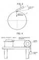
- FIG. 3 shows a schematic structure of the cleaning blade 151 contacting the photoconductive element 5.
- a linear pressure of the cleaning blade 151 against the photoconductive element 5 is 25 g/cm, and an initial contact angle thereof is 17 degrees.
- An amount of depth of the cleaning blade 151 digging into the surface of the photoconductive element 5 is 1.0 mm.
- the coefficient of static friction of the photoconductive element 5 is determined to be 0.25 according to a measurement by Euler's method as described below in reference to FIG. 4.
- Fig. 4 is a side elevation view showing measurement of the coefficient of static friction of the photoconductive element 5.
- a good quality paper of medium thickness is stretched as a belt over one fourth of a circumference of the photoconductive element 5 longitudinally in the direction of pulling. Both ends in a pulling direction of the good quality paper is provided with strings as a member supporting the paper.
- a weight of 0.98 N (100 gram) is suspended from one side of the belt.
- a force gauge installed on the other end is pulled.
- the friction coefficient of the photoconductive element 5 of the printer 1 serving as an image forming apparatus is set to a value that is set when the rotation becomes stable due to the image forming. Since the friction coefficient of the photoconductive element 5 is affected by other units arranged in the printer 1, the value is variable depending on a friction coefficient obtained immediately after the image forming is completed. However, the value of the friction coefficient may substantially become stable after 1000 of A4-size recording sheets are printed. Therefore, a friction coefficient described here is determined to be a friction coefficient obtained in a stable condition.
- Table 1 shows measurement results evaluating abrasions of nine cleaning blades A through I.
- the nine cleaning blades have different degrees of hardness by JIS-A (Japanese Industrial Standards, Division A) and different modulus of repulsion elasticity. Abrasions of the nine cleaning blades A through I were evaluated after performing respective printing operations of producing 10,000 copies each with the nine cleaning blades A through I.
- the cleaning blade 151 when the cleaning blade 151 has a degree of hardness equal to or greater than 70 by JIS-A and a degree of repulsion elasticity equal to or less than 30%, the cleaning blade 151 can stably stop the toner falling through the space between the cleaning blade151 and the photoconductive element 5, thereby increasing the removability of toner. Further, in this measurement, the cleaning blade 151 has an elongation at break equal to or greater than 20 MPa of 300% modulus or equal to or greater than 200% modulus.
- the photoconductive element 5 and the cleaning unit 15 may be integrally assembled in a process cartridge.
- the charging unit 14 and/or the developing unit 10 may be additionally integrally assembled in the process cartridge.
- the process cartridge may be detachably attached to the printer 1 for easy maintenance.
- the process cartridge may be replaced with a new one at the end of its useful life.
- small toner particles having a substantially spherical shape may be effectively removed from the photoconductive element 5 in the image forming process, thereby preventing deterioration in image quality.
- the process cartridge is useful for easy maintenance.
- a replacement of the process cartridge can restore the printer 1 to its original state easily, thereby reducing a period of time for servicing.
- a good removability of toner particles on the photoconductive element 5 may highly contribute to a long life time of the process cartridge.
- the cleaning unit 15 of the present invention may be effectively used for the printer 1 when the toner used in the developing unit 10 has high circularity, that is, the toner particles has an average circularity equal to or more than 0.93.
- the toner particles having a substantially spherical shape may be effectively removed from the photoconductive element 5. That is, the toner particles remaining on the surface of the photoconductive element 5 are first removed by the brush roller 161. The brush roller 161 then applies the molded lubricant 162 to the surface of the photoconductive element 5 so that the coefficient of friction of the photoconductive element 5 may be reduced. After the brush roller 161, the cleaning blade 151 scrapes the remaining toner to remove from the surface of the photoconductive element 5. Thus, even the small toner particles having a substantially spherical shape can be effectively removed without causing any damage to the surface of the photoconductive element 5.
- the cleaning unit 15 is preferable to clean particles of toner having a substantially spherical shape. It is preferable that a shape factor "SF1" of the toner is in a range from approximately 100 to approximately 180, and the shape factor "SF2" of the toner is in a range from approximately 100 to approximately 180.
- the shape factor "SF-1" is a parameter representing the roundness of a particle in FIG. 5A
- the shape factor "SF-2" is a parameter representing the roundness of a particle in FIG. 5B.
- the particle When the value of the shape factor "SF1" is 100, the particle has a perfect spherical shape. As the value of the "SF1" increases, the shape of the particle becomes more elliptical.
- the shape factor "SF-2" is a value representing irregularity (i.e., a ratio of convex and concave portions) of the shape of the material.
- the surface of the material is even (i.e., no convex and concave portions).
- the surface of the material becomes uneven (i.e., the number of convex and concave portions increase).
- toner images are sampled by using a field emission type scanning electron microscope (FE-SEM) S-800 manufactured by Hitachi, Ltd.
- the toner image information is analyzed by using an image analyzer (LUSEX3) manufactured by Nireko, Ltd.
- the cleaning unit 15 may easily remove the toner particles remaining on the surface of the photoconductive element 5.
- the values of the shape factors "SF1" and “SF2" exceed 100.
- the values of the shape factors "SF1" and “SF2" are preferable to be less than 180.
- the toner used in the image forming apparatus has a volume average particle size in a range from approximately 3 ⁇ m to approximately 8 ⁇ m.
- the particles of the toner are small in size and are in a range from approximately 1.00 to approximately 1.40 of ratio (Dv/Dn) of the volume average particle size (Dv) and the number average particle size (Dn) and the particle size distribution is narrow.
- Dv/Dn ratio of ratio
- the charging distribution of the toner becomes uniform and it is possible to achieve a high quality image with less excessive concentration of toner at a particular point on the paper and to have a higher transferring rate.
- the contents of fine particles of additives, etc. of the toner may be relatively high, these fine particles may be separated from the toner particles, easily causing toner filming on the surface of the photoconductive element 5.
- the brush roller 161 applies a lubricant to the surface of the photoconductive element 5 to reduce the friction coefficient of the surface of the photoconductive element 5, the cleaning blade 151 blocks the toner from passing through a gap between the photoconductive element 5 and the cleaning blade 151, thereby the toner removing performance may be more effective.
- a toner having a substantially spherical shape is preferably prepared by a method in which a toner composition dissolved or dispersed in an organic solvent, including a polyester prepolymer having a function group including a nitrogen atom, a polyester, a colorant, and a releasing agent is subjected to an elongation reaction and/or a crosslinking reaction in an aqueous medium in the presence of fine resin particles.
- Toner constituents and preferable manufacturing method of the toner of the present invention will be described below.
- the toner of the present invention includes a modified polyester (i) as binder resins.
- the toner in the present invention includes modified polyester (i) as a binder resin.
- Modified polyester means a polyester in which there is a bonding group present other than an ester bond in the polyester resin and resinous principles having a different structure in the polyester resin are bonded by a bond like covalent bond and ion bond. Concretely, it means a polyester terminal that is modified by introducing a functional group like an isocyanate group that reacts with a carboxylic acid group, a hydroxyl group to a polyester terminal and then allowed to react with a compound containing active hydrogen.
- Suitable polyesters include reaction products of a polyester prepolymer (A) having an isocyanate group with an amine (B).
- the polyester prepolymer (A) can be formed from a reaction between a polyester having an active hydrogen atom, which polyester is formed by polycondensation between a polyol (PO) and a polycarboxylic acid (PC), and a polyisocyanate (PIC).
- Specific examples of the groups including the active hydrogen include a hydroxyl group (an alcoholic hydroxyl group and a phenolic hydroxyl group), an amino group, a carboxyl group, a mercapto group, etc. In particular, the alcoholic hydroxyl group is preferably used.
- diols (DIo) and polyols having 3 or more valences (TO) can be used.
- a diol (DIO) alone or a mixture of a diol (DIO) and a small amount of polyol having 3 or more valences (TO) is preferably used.
- diol (DIO) examples include alkylene glycol such as ethylene glycol, 1,2-propylene glycol, 1,3-propylene glycol, 1,4-butanediol, and 1,6-hexanediol; alkylene ether glycol such as diethylene glycol, triethylene glycol, dipropylene glycol, polyethylene glycol, polypropylene glycol and polytetramethylene ether glycol; alicyclic diol such as 1,4-cyclohexanedimethanol and hydrogenated bisphenol A; bisphenol such as bisphenol A, bisphenol F and bisphenol S; adducts of the above-mentioned alicyclic diol with an alkylene oxide such as ethylene oxide, propylene oxide and butylene oxide; and adducts of the above-mentioned bisphenol with an alkylene oxide such as ethylene oxide, propylene oxide and butylene oxide.
- alkylene glycol such as ethylene glycol, 1,2-propylene
- alkylene glycol having 2 to 12 carbon atoms and adducts of bisphenol with an alkylene oxide are preferably used, and a mixture thereof is more preferably used.
- Specific examples of the polyol having 3 valences or more valences (TO) include multivalent aliphatic alcohol having 3 to 8 or more valences such as glycerin, trimethylolethane, trimethylolpropane, pentaerythritol and sorbitol; phenol having 3 or more valences such as trisphenol PA, phenolnovolak, cresolnovolak; and adducts of the above-mentioned polyphenol having 3 or more valences with an alkylene oxide.
- PC polycarboxylic acid
- DIC dicarboxylic acid
- TC polycarboxylic acids having 3 or more valences
- a dicarboylic acid (DIC) alone, or a mixture of the dicarboxylic acid (DIC) and a small amount of polycarboxylic acid having 3 or more valences (TC) is preferably used.
- dicarboxylic acids include alkylene dicarboxylic acids such as succinic acid, adipic acid and sebacic acid; alkenylene dicarboxylic acid such as maleic acid and fumaric acid; and aromatic dicarboxylic acids such as phthalic acid, isophthalic acid, terephthalic acid and naphthalene dicarboxylic acid.
- alkenylene dicarboxylic acid having 4 to 20 carbon atoms and aromatic dicarboxylic acid having 8 to 20 carbon atoms are preferably used.
- polycarboxylic acid having 3 or more valences include aromatic polycarboxylic acids having 9 to 20 carbon atoms such as trimellitic acid and pyromellitic acid.
- the polycarboxylic acid (PC) can be formed from a reaction between the above-mentioned acids anhydride or lower alkyl ester such as methyl ester, ethyl ester and isopropyl ester.
- the polyol (PO) and the polycarboxylic acid (PC) are mixed such that the equivalent ratio ([OH] /[COOH]) between the hydroxyl group [OH] of the polyol (1) and the carboxylic group [COOH] of the polyol carboxylic acid (2) is typically from 2/1 to 1/1, preferably from 1.5/1 to 1/1 and more preferably from 1.3/1 to 1.02/1.
- polyisocyanate examples include aliphatic polyisocyanate such as tetramethylenediisocyanate, hexamethylenediisocyanate and 2, 6-diisocyanatemethylcaproate; alicyclic polyisocyanate such as isophoronediisocyanate and cyclohexylmethanediisocyanate; 10 aromatic diisocyanate such as tolylenedisocyanate and diphenylmethanediisocyanate; aroma aliphatic diisocyanate such as .alpha., .alpha.,' .alpha.'-te-tramethylxylylenediisocyanate; isocyanurate; the above-mentioned polyisocyanate blocked with phenol derivatives, oxime and caprolactam; and their combinations.
- aliphatic polyisocyanate such as tetramethylenediisocyanate, hexamethylenediisocyanate and 2, 6-diis
- the polyisocyanate (PIC) is mixed with a polyester such that the equivalent ratio ([NCO] / [OH]) between the isocyanate group [NCO] of the polyisocyanate (PIC) and the hydroxyl group [OH] of the polyester is typically from 5/1 to 1/1, preferably from 4/1 to 1.2/1 and more preferably from 2.5/1 to 1.5/1.
- [NCO]/[OH] is greater than 5
- low temperature fixability of the resultant toner deteriorates.
- the molar ratio of [NCO] is less than 1, the urea content in the resultant modified polyester decreases and hot offset resistance of the resultant toner deteriorates.
- the content of the constitutional unit obtained from a polyisocyanate (PIC) in the polyester prepolymer (A) is from 0.5% to 40% by weight, preferably from 1% to 30% by weight and more preferably from 2% to 20% by weight.
- PIC polyisocyanate
- the content is less than 0.5% by weight, hot offset resistance of the resultant toner deteriorates and in addition the heat resistance and low temperature fixability of the toner also deteriorate.
- the content is greater than 40% by weight, low temperature fixability of the resultant toner deteriorates.
- the number of the isocyanate groups included in a molecule of the polyester prepolymer (A) is at least 1, preferably from 1.5 to 3 on average, and more preferably from 1.8 to 2.5 on average.
- the number of the isocyanate group is less than 1 per 1 molecule, the molecular weight of the urea-modified polyester decreases and hot offset resistance of the resultant toner deteriorates.
- amines (B) include diamines (B1), polyamines (B2) having three or more amino groups, amino alcohols (B3), amino mercaptans (B4), amino acids (B5) and blocked amines (B6) in which the amines (B1-B5) mentioned above are blocked.
- diamines (B1) include aromatic diamines (e.g., phenylene diamine, diethyltoluene diamine and 4,4'-diaminodiphenyl methane); alicyclic diamines (e.g., 4,4'-diamino-3,3'-dimethyldicyclohexyl methane, diamino cyclohexane and isophoron diamine); aliphatic diamines (e.g., ethylene diamine, tetramethylene diamine and hexamethylene diamine); etc.
- polyamines (B2) having three or more amino groups include diethylene triamine, triethylene tetramine.
- amino alcohols (B3) include ethanol amine and hydroxyethyl aniline.
- amino mercaptan (B4) include aminoethyl mercaptan and aminopropyl mercaptan.
- amino acid (B5) are aminopropionic acid and caproic acid.
- Specific examples of the blocked amines (B6) include ketimine compounds which are prepared by reacting one of the amines B1-B5 mentioned above with a ketone such as acetone, methyl ethyl ketone and methyl isobutyl ketone; oxazoline compounds, etc.
- diamines (B1) and mixtures in which a diamine is mixed with a small amount of a polyamine (B2) are preferably used.
- the mixing ratio (i.e., a ratio [NCO] / [NHx]) of the content of the prepolymer (A) having an isocyanate group to the amine (B) is from 1/2 to 2/1, preferably from 1.5/1 to 1/1.5 and more preferably from 1.2/1 to 1/1.2.
- the mixing ratio is greater than 2 or less than 1/2, molecular weight of the urea-modified polyester decreases, resulting in deterioration of hot offset resistance of the resultant toner.
- Suitable polyester resins for use in the toner of the present invention include a urea-modified polyesters (i).
- the urea-modified polyester (i) may include a urethane bonding as well as a urea bonding.
- the molar ratio (urea/urethane) of the urea bonding to the urethane bonding is from 100/0 to 10/90, preferably from 80/20 to 20/80 and more preferably from 60/40 to 30/70. When the molar ratio of the urea bonding is less than 10%, hot offset resistance of the resultant toner deteriorates.
- Modified polyesters such as the urea-modified polyester (i) can be produced by a method such as one-shot methods and prepolymer methods.
- the weight-average molecular weight of the urea-modified polyester (i) is not less than 10,000, preferably from 20,000 to 10,000,000 and more preferably from 30,000 to 1,000,000.
- the peak molecular weight is preferably from 1,000 to 10,000. When the peak molecular weight is less than 1,000, an elongation reaction tends not to occur and elasticity of the toner is low, hence hot offset resistance of the resultant toner deteriorates.
- the peak molecular weight is more than approximately 10,000, fixability is impaired and manufacturing problems may occur for example in the particle formation process or the pulverization process.
- the number-average molecular weight of the urea-modified polyester (i) is not particularly limited when the after-mentioned unmodified polyester resin (ii) is used in combination. Namely, the weight-average molecular weight of the urea-modified polyester resins has priority over the number-average molecular weight thereof. However, when the urea-modified polyester (i) is used alone, the number-average molecular weight is not greater than 20,000, preferably from 1,000 to 10,000, and more preferably from 2,000 to 8,000. When the number-average molecular weight is greater than 20,000, the low temperature fixability of the resultant toner deteriorates, and in addition the glossiness of full color images deteriorates.
- a reaction anticatalyst can optionally be used in the crosslinking and/or elongation reaction between the polyester prepolymer (A) and amines (B) to control a molecular weight of the resultant urea-modified polyesters, if desired.
- Specific examples of the reaction anticatalyst include monoamines such as diethyl amine, dibutyl amine, butyl amine and lauryl amine, and blocked amines, i.e., ketimine compounds prepared by blocking the monoamines mentioned above.
- not only the urea-modified polyester (i) alone but also the unmodified polyester resin (ii) can be included as a toner binder with the urea-modified polyester (i).
- a combination thereof improves low temperature fixability of the resultant toner and glossiness of color images produced thereby, and using the combination is more preferable than using the urea-modified polyester (i) alone.
- Suitable unmodified polyester resin (ii) includes polycondensation products of a polyol (PO) and a polycarboxylic acid (PC) similarly to the urea-modified polyester (i).
- Specific examples of the polyol (PO) and the polycarboxylic acid (PC) are the same as those for use in the urea-modified polyester (i).
- Polyester resins modified by a bonding such as urethane bonding other than a urea bonding can be considered to be the unmodified polyester in the present invention. It is preferable that the urea-modified polyester (i) at least partially mixes with the unmodified polyester resin (ii) to improve the low temperature fixability and hot offset resistance of the resultant toner.
- the urea-modified polyester (i) preferably has a structure similar to that of the unmodified polyester resin (ii).
- a mixing ratio ((i)/(ii)) between the urea-modified polyester (i) and polyester resin (ii) is from 5/95 to 80/20 by weight, preferably from 5/95 to 30/70 by weight, more preferably from 5/95 to 25/75 by weight, and even more preferably from 7/93 to 20/80 by weight.
- the weight ratio of the urea-modified polyester (i) is less than 5%, the hot offset resistance deteriorates, and in addition, it is difficult to impart a good combination of high temperature preservability and low temperature fixability of the toner.
- the peak molecular weight of the unmodified polyester (ii) is generally 1,000 to 10,000, preferably 2,000 to 8,000, and more preferably 2,000 to 5,000. When the peak molecular weight thereof is less than approximately 1,000, heat-resistant storability is impaired. When the peak molecular weight thereof is more than approximately 10,000, low temperature fixability is impaired. It is preferable that the hydroxyl value of (ii) is not less than 5. The value in a range of 10 to 120 is more preferable and a range of 20 to 80 is particularly preferable. The hydroxyl value thereof is less than approximately 5, it is difficult to impart a good combination of heat resistance storability and low temperature fixability.
- the acid value of the unmodified polyester (ii) is approximately 1 to approximately 5, and preferable 2 to 4.
- the wax having a high acid value is generally used as a wax component of the toner, it is preferable to use the resin having a low acid value as a toner binder because good charge property and high volume resistivity can be imparted to the resultant toner.
- the toner formed from such a wax and a resin is suitable for a two-component toner.
- the toner binder preferably has a glass transition temperature (Tg) of from 35 °C to 70 °C, and preferably from 55 C° to 65 °C.
- Tg glass transition temperature
- the glass transition temperature is less than 35 °C.
- the high temperature preservability of the toner deteriorates.
- the glass transition temperature is higher than 70 °C.
- the low temperature fixability deteriorates. Due to a combination of the modified polyester such as urea-modified polyester and polyester resin, the toner of the present invention has better high temperature preservability than conventional toners including a polyester resin as a binder resin even though the glass transition temperature is low.
- Suitable colorants for use in the toner of the present invention include known dyes and pigments.
- Specific examples of the colorants include carbon black, Nigrosine dyes, black iron oxide, Naphthol Yellow S, Hansa Yellow (10G, 5G and G), Cadmium Yellow, yellow iron oxide, loess, chrome yellow, Titan Yellow, polyazo yellow, Oil Yellow, Hansa Yellow (GR, A, RN and R), Pigment Yellow L, Benzidine Yellow (G and GR), Permanent Yellow (NCG), Vulcan Fast Yellow (5G and R), Tartrazine Lake, 25 Quinoline Yellow Lake, Anthrazane Yellow BGL, isoindolinone yellow, red iron oxide, red lead, orange lead, cadmium red, cadmium mercury red, antimony orange, Permanent Red 4R, Para Red, Fire Red, p-chloro-o-nitroaniline red, LitholFast Scarlet G, Brilliant Fast Scarlet, Brilliant Carmine BS, Permanent Red (F2R, F4R, FRL, FR
- a content of the colorant in the toner is preferably from 1% by weight to 15% by weight, and more preferably from 3% by weight to 10 % by weight, based on total weight of the toner.
- the colorants mentioned above for use in the present invention can be used as master batch pigments by being combined with a resin.
- binder resins to be kneaded with the master batch or used in the preparation of the master batch are styrenes like polystyrene, poly-p- chlorostyrene, polyvinyl toluene and polymers of their substitutes, or copolymers of these with a vinyl compound, polymethyl metacrylate, polybutyl metacrylate, polyvinyl chloride, polyvinyl acetate, polyethylene, polypropylene, polyester, epoxy resins, epoxy polyol resins, polyurethane, polyamides, polyvinyl butyral, polyacrylic resins, rosin, modified rosin, terpene resins, aliphatic and alicyclic hydrocarbon resins, aromatic petroleum resins, chlorinated paraffins, paraffin wax etc. which can be used alone or in combination.
- charge controlling agent examples include known charge controlling agents such as Nigrosine dyes, triphenylmethane dyes, metal complex dyes including chromium, chelate compounds of molybdic acid, Rhodaminedyes, alkoxyamines, quaternary ammonium salts (including fluorine-modified quaternary ammonium salts), alkylamides, phosphor and compounds including phosphor, tungsten and compounds including tungsten, fluorine-containing activators, metal salts of salicylic acid, salicylic acid derivatives, etc.
- charge controlling agents such as Nigrosine dyes, triphenylmethane dyes, metal complex dyes including chromium, chelate compounds of molybdic acid, Rhodaminedyes, alkoxyamines, quaternary ammonium salts (including fluorine-modified quaternary ammonium salts), alkylamides, phosphor and compounds including phosphor, tungsten and compounds including tungsten, fluor
- a content of the charge controlling agent is determined depending on the species of the binder resin used, whether or not an additive is added and toner manufacturing method (such as dispersion method) used, and is not particularly limited.
- the content of the charge controlling agent is typically from 0.1 to 10 parts by weight, and preferably from 0.2 to 5 parts by weight, per 100 parts by weight of the binder resin included in the toner.
- the content is too high, the toner has too large charge quantity, and thereby the electrostatic force of a developing roller attracting the toner increases, resulting in deterioration of the fluidity of the toner and decrease of the image density of toner images.
- a wax for use in the toner of the present invention as a releasing agent has a low melting point of from 50 °C to 120 °C.
- the wax is dispersed in the binder resin and serves as a releasing agent at a location between a fixing roller and the toner particles.
- the releasing agent include natural waxes such as vegetable waxes, e.g., carnauba wax, cotton wax, Japan wax and rice wax; animal waxes, e.g., bees wax and lanolin; mineral waxes, e.g., ozokelite and ceresine; and petroleum waxes, e.g., paraffin waxes, microcrystalline waxes and petrolatum.
- synthesized waxes can also be used.
- synthesized waxes include synthesized hydrocarbon waxes such as Fischer-Tropsch waxes and polyethylene waxes; and synthesized waxes such as ester waxes, ketone waxes and ether waxes.
- fatty acid amides such as 1,2-hydroxylstearic acid amide, stearic acid amide and phthalic anhydride imide
- low molecular weight crystalline polymers such as acrylic homopolymer and copolymers having a long alkyl group in their side chain, e.g., poly-n-stearyl methacrylate, poly-n- laurylmethacrylate and n-stearyl acrylate-ethyl methacrylate copolymers, can also be used.
- charge controlling agent and releasing agents can be dissolved and dispersed after kneaded upon application of heat together with a master batch pigment and a binder resin, and can be added when directly dissolved and dispersed in an organic solvent.
- the inorganic particulate material preferably has a primary particle diameter of from 5 x 10 -3 ⁇ m to 2 ⁇ m, and more preferably from 5 x 10 -3 ⁇ m to 0.5 ⁇ m.
- a specific surface area of the inorganic particulates measured by a BET method is preferably from 20 m 2 /g to 500 m 2 /g.
- the content of the external additive is preferably from 0.01% by weight to 5% by weight, and more preferably from 0.01% by weight to 2.0% by weight, based on total weight of the toner.
- the inorganic fine grains are silica, alumina, titanium oxide, barium titanate, magnesium titanate, calcium tiatanate, strontium titanate, zinc oxide, tin oxide, quartz sand, clay, mica, wollastonite, diatomaceous earth, chromium oxide, cerium oxide, red oxide, antimony trioxide, magnesium oxide, zirconium oxide, barium sulfate, barium carbonate, calcium carbonate, silicon carbide, and silicon nitride.
- hydrophobic silica fine grains and hydrophobic titanium oxide fine grains in combination it is preferable to use.
- the fluidity imparting agent does not part from the toner grains and insures desirable image quality free from spots or similar image defects. In addition, there can be reduced the amount of residual toner.
- Titanium oxide fine grains are desirable in environmental stability and image density stability, but tend to lower in charge start characteristics. Therefore, if the amount of titanium oxide fine particles is larger than the amount of silica fine grains, then the influence of the above side effect is considered to increase. However, so long as the amount of hydrophobic silica fine grains and hydrophobic titanium oxide fine grains is between 0.3% by weight and 1.5% by weight, the charge start characteristics are not noticeably impaired, i.e., desired charge start characteristics are achievable. Consequently, stable image quality is achievable despite repeated copying operation.
- the toner of the present invention is produced by the following method, but the manufacturing method is not limited thereto.
- a colorant, unmodified polyester, polyester prepolymer having isocyanate groups and a parting agent are dispersed into an organic solvent to prepare a toner material liquid.
- the organic solvent should preferably be volatile and have a boiling point of 100 °C or below because such a solvent is easy to remove after the formation of the toner mother particles. More specific examples of the organic solvent includes one or more of toluene, xylene, benzene, carbon tetrachloride, methylene chloride, 1,2-dichloroethane, 1,1,2-trichloroethane, trichloro ethylene, chloroform, monochlorobenzene, dichloroethylidene, methyl acetate, ethyl acetate, methyl ethyl ketone, methyl isobutyl ketone, and so forth.
- the aromatic solvent such as toluene and xylene; and a hydrocarbon halide such as methylene chloride, 1,2-dichloroethane, chloroform or carbon tetrachloride is preferably used.
- the amount of the organic solvent to be used should preferably 0 parts by weight to 300 parts by weight for 100 parts by weight of polyester prepolymer, more preferably 0 parts by weight to 100 parts by weight for 100 parts by weight of polyester prepolymer, and even more preferably 25 parts by weight to 70 parts by weight for 100 parts by weight of polyester prepolymer.
- the toner material liquid is emulsified in an aqueous medium in the presence of a surfactant and organic fine particles.
- the aqueous medium for use in the present invention is water alone or a mixture of water with an organic solvent which can be mixed with water.
- organic solvent include alcohols (e.g., methanol, isopropyl alcohol and ethylene glycol), dimethylformamide, tetrahydrofuran, cellosolves (e.g., methyl cellosolve), lower ketones (e.g., acetone and methyl ethyl ketone), etc.
- the content of the aqueous medium is typically from 50 parts by weight to 2,000 parts by weight, and preferably from 100 parts by weight to 1,000 parts by weight, per 100 parts by weight of the toner constituents.
- the content is less than 50 parts by weight, the dispersion of the toner constituents in the aqueous medium is not satisfactory, and thereby the resultant mother toner particles do not have a desired particle diameter.
- the content is greater than 2,000, the manufacturing costs increase.
- dispersants are used to emulsify and disperse an oil phase in an aqueous liquid including water in which the toner constituents are dispersed.
- dispersants include surfactants, resin fine-particle dispersants, etc.
- dispersants include anionic surfactants such as alkylbenzenesulfonic acid salts, .alpha.-olefin sulfonic acid salts, and phosphoric acid salts; cationic surfactants such as amine salts (e.g., alkyl amine salts, aminoalcohol fatty acid derivatives, polyamine fatty acid derivatives and imidazoline), and quaternary ammonium salts (e.g., alkyltrimethylammonium salts, dialkyldimethylammonium salts, alkyldimethyl benzyl ammonium salts, pyridinium salts, alkyl isoquinolinium salts and benzethonium chloride); nonionic surfactants such as fatty acid amide derivatives, polyhydric alcohol derivatives; and ampholytic surfactants such as alanine, dodecyldi(aminoethyl)glycine, di(octylaminoe
- a surfactant having a fluoroalkyl group can prepare a dispersion having good dispersibility even when a small amount of the surfactant is used.
- anionic surfactants having a fluoroalkyl group include fluoroalkyl carboxylic acids having from 2 to 10 carbon atoms and their metal salts, disodium perfluorooctanesulfonylglutamate, sodium 3- ⁇ omega-fluoroalkyl (C6-C11) oxy ⁇ -1-alkyl(C3-C4) sulfonate, sodium, 3-lomega-fluoroalkanoyl(C6-C8)-N-ethylamino ⁇ -1- propanesulfonate, fluoroalkyl(C11-C20) carboxylic acids and their metal salts, perfluoroalkylcarboxylic acids (7C-13C) and their metal salts, perfluoroalkyl(C4-C12)sulfonate and their
- Specific examples of the marketed products of such surfactants having a fluoroalkyl group include SARFRON (trademark registered) S-111, S-112 and S-113, which are manufactured by Asahi Glass Co., Ltd.; FLUORAD (trademark registered) FC-93, FC-95, FC-98 and FC-129, which are manufactured by Sumitomo 3M Ltd.; UNIDYNE (trademark registered) DS-101 and DS-102, which are manufactured by Daikin Industries, Ltd.; MEGAFACE (trademark registered) F-110, F-120, F-113, F-191, F-812 and F-833 which are manufactured by DainipponInk and Chemicals, Inc.; ECTOP EF-102, 103, 104, 105, 112, 123A, 123B, 306A, 501, 201 and 204, which are manufactured by Tohchem Products Co., Ltd.; FUTARGENT (trademark registered) F-100 and F150 manufactured by Neos; etc.
- cationic surfactants which can disperse an oil phase including toner constituents in water, include primary, secondary and tertiary aliphatic amines having a fluoroalkyl group, aliphatic quaternary ammonium salts such as perfluoroalkyl(C6-C10)sulfoneamidepropyltrimethylammonium salts, benzalkonium salts, benzetonium chloride, pyridinium salts, imidazolinium salts, etc.
- Specific examples of the marketed products thereof include SARFRON (trademark registered) S-121 (from Asahi Glass Co., Ltd.); FLUORAD (trademark registered) FC-135 (from Sumitomo 3M Ltd.); UNIDYNE DS-202 (from Daikin Industries, Ltd.); MEGAFACE (trademark registered) F-150 and F-824 (from Dainippon Ink and Chemicals, Inc.); ECTOP EF-132 (from Tohchem Products Co., Ltd.); FUTARGENT (trademark registered) F-300 (from Neos); etc.
- the resin constituting the fine polymer particles can be any known resin, as long as it can form an aqueous dispersion, and can be either a thermoplastic resin or a thermosetting resin.
- resins are vinyl resins, polyurethane resins, epoxy resins, polyester resins, polyamide resins, polyimide resins, silicone resins, phenolic resins, melamine resins, urea resins, aniline resins, ionomer resins, and polycarbonate resins. Each of these resins can be used alone or in combination.
- vinyl resins, polyurethane resins, epoxy resins, polyester resins, and mixtures of these resins are preferred for easily preparing an aqueous dispersion of fine spherical polymer particles.
- vinyl resins are homopolymers or copolymers of vinyl monomers, such as styrene-acrylic ester resins, styrene-methacrylic ester resins, styrene-butadiene copolymers, acrylic acid-acrylic ester copolymers, methacrylic acid-acrylic ester copolymers, styreneacrylonitrile copolymers, styrene-maleic anhydride copolymers, styrene-acrylic acid copolymers and styrene-methacrylic acid copolymers.
- An average particle diameter of the resin constituting the fine polymer particles is preferably from approximately 5 nm to approximately 200 nm, and more preferably from approximately 20 nm to approximately 300 nm.
- inorganic compounds such as tricalcium phosphate, calcium carbonate, titanium oxide, colloidal silica, and hydroxyapatite can be also used as the dispersing agent.
- protection colloids include polymers and copolymers prepared using monomers such as acids (e.g., acrylic acid, methacrylic acid, .alpha.-cyanoacrylic acid, .alpha.-cyanomethacrylic acid, itaconic acid, crotonic acid, fumaric acid, maleic acid and maleic anhydride), acrylic monomers having a hydroxyl group (e.g., .beta.-hydroxyethyl acrylate, .beta.-hydroxyethyl methacrylate, .beta.-hydroxypropyl acrylate, (.beta.-hydroxypropyl methacrylate, .gamma.-hydroxypropyl acrylate, .gamma.-hydroxypropyl methacrylate, 3-chloro-2-hydroxyprop
- polymers such as polyoxyethylene compounds (e.g., polyoxyethylene, polyoxypropylene, polyoxyethylenealkyl amines, polyoxypropylenealkyl amines, polyoxyethylenealkyl amides, polyoxypropylenealkyl, amides, polyoxyethylene nonylphenyl ethers, polyoxyethylene laurylphenyl ethers, polyoxyethylene stearylphenyl esters, and polyoxyethylene nonylphenyl esters); and cellulose compounds such as methyl cellulose, hydroxyethylcellulose and hydroxypropylcellulose, can also be used as the polymeric protective colloid.
- polyoxyethylene compounds e.g., polyoxyethylene, polyoxypropylene, polyoxyethylenealkyl amines, polyoxypropylenealkyl amines, polyoxyethylenealkyl amides, polyoxypropylenealkyl, amides, polyoxyethylene nonylphenyl ethers, polyoxyethylene laurylphenyl ethers, polyoxy
- the dispersion method is not particularly limited, and conventional dispersion facilities, e.g., low speed shearing type, high speed shearing type, friction type, high pressure jet type and ultrasonic type dispersers can be used.
- the high speed shearing type dispersion methods are preferable for preparing a dispersion including grains with a grain size of 2 to 20 ⁇ m.
- the number of rotation of the high speed shearing type dispersers is not particularly limited, but is usually 1,000 rpm (revolutions per minute) to 30,000 rpm, and preferably 5,000 rpm to 20,000 rpm.
- the dispersion time is not limited, it is usually 0.1 minute to 5 minutes for the batch system.
- the dispersion temperature is usually 0 °C to 150 °C, and preferably 40 °C to 98 °C under a pressurized condition.
- an amine (B) is added to the emulsion to be reacted with the polyester prepolymer (A) having isocyanate groups.
- the reaction causes the crosslinking and/or extension of the molecular chains to occur.
- the elongation and/or crosslinking reaction time is determined depending on the reactivity of the isocyanate structure of the prepolymer (A) and amine (B) used, but is typically from 10 minnutes to 40 hours, and preferably from 2 hours to 24 hours.
- the reaction temperature is typically from 0 °C to 150 °C, and preferably from 40 °C to 98 °C.
- a known catalyst such as dibutyltinlaurate and dioctyltinlaurate can be used.
- the amines (B) are used as the elongation agent and/or crosslinker.
- the entire system is gradually heated in a laminar-flow agitating state.
- fusiform mother toner particles can be produced.
- a dispersion stabilizer e.g., calcium phosphate, which is soluble in acid or alkali
- calcium phosphate is preferably removed from the toner mother particles by being dissolved by hydrochloric acid or similar acid, followed by washing with water. Further, such a dispersion stabilizer can be removed by a decomposition method using an enzyme.
- the penetration of the charge controlling agent and addition of the inorganic fine particles can be carried out using a conventional mixer.
- the particle shape of the particles can be controlled so as to be any shape between perfectly spherical and rugby ball shape.
- the conditions of the surface can also be controlled so as to be any condition between smooth surface and rough surface such as the surface of pickled plum.
- the toner used in the image forming apparatus 1 may be substantially spherical.
- An axis x of FIG. 6A represents a major axis r1 of FIG. 6B, which is the longest axis of the toner.
- An axis y of FIG. 6A represents a minor axis r2 of FIG. 6B, which is the second longest axis of the toner.
- the axis z of FIG. 6A represents a thickness r3 of FIG. 6B, which is a thickness of the shortest axis of the toner.
- the toner has a relationship between the major and minor axes r1 and r2 and the thickness r3 as follows: r1 ⁇ r2 ⁇ r3.
- the toner of FIG. 6A is preferably in a spindle shape in which the ratio (r2/r1) of the major axis r1 to the minor axis r2 is approximately 0.5 to approximately 0.8, and the ratio (r3/r2) of the thickness r3 to the minor axis is approximately 0.7 to approximately 1.0.
- the toner When the ratio (r2/r1) is less than approximately 0.5, the toner has an irregular particle shape, and the rates of the dot reproducibility and transfer efficiency may decrease, resulting in degrading image quality.
- the toner When the ratio (r3/r2) is less than approximately 0.7, the toner has an irregular particle shape, and the transferability may be degraded compared to transferability obtained with substantially spherical toner particles.
- the ratio (r3/r2) is approximately 1.0, the toner has a substantially spherical shape, and the fluidity of toner may increase.
- the lengths showing with r1, r2 and r3 can be monitored and measured with scanning electron microscope (SEM) by taking pictures from different angles.
- SEM scanning electron microscope
- the toner for electro photography of the present invention can be used as a one-component magnetic or nonmagnetic toner without a carrier or in combination with magnetic carriers in a two-component developer.
- the magnetic material used in the carrier includes a ferrite including a bivalent metal like iron, magnetite, Mn, Zn, Cu etc. with a desirable volume average particle size in a range of approximately 20 ⁇ m to approximately 100 ⁇ m.
- the average particle size is smaller than 20 ⁇ m, the carrier is easily adhered to the photoconductive element 5 during developing.
- the average particle size is greater than 100 ⁇ m, the magnetic material doesn't mix well with the toner and the toner is not sufficiently charged, thereby causing defective charging during continuous use.
- the a copper ferrite that includes zinc is used as the magnetic material due to its high saturation magnetization
- a suitable magnetic material can be selected according to the process of the printer 1 serving as an image forming apparatus.
- the resins that coat the magnetic carrier are not limited to any particular resins, but specific examples of the coating resins for the magnetic carrier are silicone resins, styrene-acrylic resins, fluorine resins, olefin resins, and the like.
- the coating resin is dissolved in a solvent, sprayed in the fluid bed, and then coated on the core.
- the resin particles are electrostatically adhered to the nucleons and are then coated by thermal melting.
- the thickness of the coated resin is preferably in a range from approximately 0.05 ⁇ m to approximately 10 ⁇ m, and more preferably from approximately 0.3 ⁇ m to approximately 4 ⁇ m.
Landscapes
- Physics & Mathematics (AREA)
- General Physics & Mathematics (AREA)
- Spectroscopy & Molecular Physics (AREA)
- Chemical & Material Sciences (AREA)
- Chemical Kinetics & Catalysis (AREA)
- Inorganic Chemistry (AREA)
- Engineering & Computer Science (AREA)
- Mechanical Engineering (AREA)
- Cleaning In Electrography (AREA)
- Developing Agents For Electrophotography (AREA)
Applications Claiming Priority (2)
| Application Number | Priority Date | Filing Date | Title |
|---|---|---|---|
| JP2004112681 | 2004-04-07 | ||
| JP2004112681A JP2005300626A (ja) | 2004-04-07 | 2004-04-07 | クリーニング装置、画像形成装置 |
Publications (3)
| Publication Number | Publication Date |
|---|---|
| EP1586958A2 true EP1586958A2 (de) | 2005-10-19 |
| EP1586958A3 EP1586958A3 (de) | 2005-11-16 |
| EP1586958B1 EP1586958B1 (de) | 2019-01-16 |
Family
ID=34934611
Family Applications (1)
| Application Number | Title | Priority Date | Filing Date |
|---|---|---|---|
| EP05007004.4A Expired - Lifetime EP1586958B1 (de) | 2004-04-07 | 2005-03-31 | Reinigungsvorrichtung mit einem reibungsverminderenden Element |
Country Status (5)
| Country | Link |
|---|---|
| US (1) | US7292816B2 (de) |
| EP (1) | EP1586958B1 (de) |
| JP (1) | JP2005300626A (de) |
| KR (1) | KR100741338B1 (de) |
| CN (1) | CN100394329C (de) |
Cited By (3)
| Publication number | Priority date | Publication date | Assignee | Title |
|---|---|---|---|---|
| EP1768003A1 (de) * | 2005-09-22 | 2007-03-28 | Ricoh Company, Ltd. | Schmiermittelzufuhrvorrichtung, Bilderzeugungsvorrichtung und Pressvorrichtung |
| EP1801663A3 (de) * | 2005-12-21 | 2008-07-23 | Sumitomo Rubber Industries, Ltd. | Reinigungsklinge zur Verwendung in einem Bilderzeugungsgerät |
| EP2738623A3 (de) * | 2012-11-30 | 2016-09-28 | Samsung Electronics Co., Ltd | Reinigungsklingen mit hervorragender Reinigungsleistung und Haltbarkeit, Reinigungseinheiten, elektrophotographische Abbildungsvorrichtung und elektrophotographische Kartuschen damit |
Families Citing this family (22)
| Publication number | Priority date | Publication date | Assignee | Title |
|---|---|---|---|---|
| US20030096185A1 (en) * | 2001-09-21 | 2003-05-22 | Hiroshi Yamashita | Dry toner, method for manufacturing the same, image forming apparatus, and image forming method |
| JP2004334092A (ja) * | 2003-05-12 | 2004-11-25 | Ricoh Co Ltd | クリーニング装置、プロセスカートリッジ、画像形成装置、及びこれらに用いるトナー |
| JP4647232B2 (ja) | 2003-06-24 | 2011-03-09 | 株式会社リコー | プロセスカートリッジ及び画像形成装置 |
| JP2005024665A (ja) | 2003-06-30 | 2005-01-27 | Ricoh Co Ltd | 粉体搬送装置、画像形成装置、トナー収容部及びプロセスカートリッジ |
| JP2005300626A (ja) | 2004-04-07 | 2005-10-27 | Ricoh Co Ltd | クリーニング装置、画像形成装置 |
| US7373101B2 (en) * | 2004-12-28 | 2008-05-13 | Ricoh Co., Ltd. | Method and apparatus for image forming and effectively applying lubricant to an image bearing member |
| JP2006208418A (ja) * | 2005-01-25 | 2006-08-10 | Ricoh Co Ltd | 画像形成装置、プロセスカートリッジ、トナー |
| JP4536628B2 (ja) * | 2005-09-16 | 2010-09-01 | 株式会社リコー | 画像形成装置、プロセスカートリッジ、画像形成方法 |
| JP2007171923A (ja) * | 2005-11-25 | 2007-07-05 | Ricoh Co Ltd | 現像装置、及び画像形成装置 |
| JP4900796B2 (ja) * | 2005-12-19 | 2012-03-21 | シンジーテック株式会社 | クリーニングブレード部材 |
| JP2008096948A (ja) * | 2006-09-12 | 2008-04-24 | Ricoh Co Ltd | 画像形成装置、プロセスカートリッジ |
| EP1909147A3 (de) * | 2006-10-02 | 2013-04-03 | Sumitomo Rubber Industries, Ltd. | Reinigungsklinge zur Verwendung in einem Bilderzeugungsgerät |
| US7885595B2 (en) * | 2007-09-04 | 2011-02-08 | Ricoh Company Limited | Lubricant applicator, process cartridge including same, and image forming apparatus including same |
| JP5063291B2 (ja) * | 2007-10-19 | 2012-10-31 | 株式会社リコー | 潤滑剤供給装置、プロセスカートリッジ、画像形成装置、潤滑剤供給部材、及び、サプライ |
| JP5073463B2 (ja) | 2007-11-30 | 2012-11-14 | 株式会社リコー | クリーニング装置、像担持体ユニット及び画像形成装置 |
| JP4687761B2 (ja) * | 2008-09-02 | 2011-05-25 | 富士ゼロックス株式会社 | 清掃部材、清掃器、像保持体ユニットおよび画像形成装置 |
| JP2010169899A (ja) * | 2009-01-23 | 2010-08-05 | Ricoh Co Ltd | クリーニング装置、プロセスカートリッジ、画像形成装置 |
| JP5375350B2 (ja) * | 2009-06-12 | 2013-12-25 | 株式会社リコー | クリーニング装置、プロセスカートリッジおよび画像形成装置 |
| JP4936481B2 (ja) * | 2009-08-31 | 2012-05-23 | 株式会社沖データ | クリーニング装置およびそれを備えた画像形成装置 |
| JP5424106B2 (ja) * | 2009-09-10 | 2014-02-26 | 株式会社リコー | 画像形成装置 |
| JP2011150311A (ja) * | 2009-12-21 | 2011-08-04 | Canon Inc | 画像形成装置 |
| JP5850301B2 (ja) | 2010-11-04 | 2016-02-03 | 株式会社リコー | 画像形成装置 |
Family Cites Families (112)
| Publication number | Priority date | Publication date | Assignee | Title |
|---|---|---|---|---|
| US4562136A (en) * | 1982-03-05 | 1985-12-31 | Ricoh Company, Ltd. | Two-component dry-type developer |
| DE3312741C2 (de) * | 1982-04-08 | 1985-07-04 | Ricoh Co., Ltd., Tokio/Tokyo | Trägerteilchen für elektrostatographische Entwickler und deren Verwendung |
| JPH06105364B2 (ja) * | 1984-06-06 | 1994-12-21 | 株式会社リコー | 電子写真用正荷電性トナー |
| JPH0654396B2 (ja) * | 1985-08-29 | 1994-07-20 | 株式会社リコー | 静電荷像現像用トナ− |
| US4762763A (en) * | 1985-12-19 | 1988-08-09 | Ricoh Co., Ltd. | Toner for developing electrostatic latent image |
| US4888263A (en) | 1985-12-19 | 1989-12-19 | Ricoh Co., Ltd. | Color toner for electrophotography |
| JP2806453B2 (ja) * | 1987-12-16 | 1998-09-30 | 株式会社リコー | 静電荷像現像用乾式カラートナー |
| US5244765A (en) * | 1990-03-15 | 1993-09-14 | Ricoh Company, Ltd. | Toner for developing latent electrostatic images |
| JP3090485B2 (ja) | 1990-04-26 | 2000-09-18 | 株式会社リコー | トナー |
| US5225303A (en) * | 1990-10-05 | 1993-07-06 | Ricoh Company, Ltd. | Dry-type toner including waxes release agent for electrophotography |
| US5384628A (en) * | 1992-10-10 | 1995-01-24 | Ricoh Company, Ltd. | Developing device for image forming equipment |
| JP3467061B2 (ja) * | 1993-06-25 | 2003-11-17 | 株式会社リコー | 操作部及び画像形成装置 |
| US5572293A (en) * | 1993-10-14 | 1996-11-05 | Ricoh Company, Ltd. | Method of and system for cleaning a charge inducing member |
| DE19534384B4 (de) * | 1994-09-16 | 2015-08-20 | Ricoh Co., Ltd. | Farb-Trockentoner für die Elektrophotographie und Herstellung desselben |
| US5596395A (en) * | 1994-09-21 | 1997-01-21 | Ricoh Company, Ltd. | Image forming apparatus and its control system having a single device for moving a charging member and a transfer member |
| JPH08166705A (ja) * | 1994-10-11 | 1996-06-25 | Ricoh Co Ltd | 画像形成装置 |
| JPH08211755A (ja) * | 1994-11-15 | 1996-08-20 | Ricoh Co Ltd | 画像形成装置 |
| JPH09106105A (ja) * | 1995-08-08 | 1997-04-22 | Ricoh Co Ltd | カラートナー |
| US5851716A (en) | 1996-04-08 | 1998-12-22 | Ricoh Company, Ltd. | Electrophotographic image forming method and toner composition used therefor |
| JPH1069155A (ja) * | 1996-05-29 | 1998-03-10 | Ricoh Co Ltd | 画像形成装置 |
| DE69717545T2 (de) * | 1996-06-18 | 2003-11-20 | Ricoh Co., Ltd. | Tonerzuführeinrichtung und Bilderzeugungsgerät |
| JPH1073976A (ja) * | 1996-07-03 | 1998-03-17 | Ricoh Co Ltd | 画像形成装置 |
| JP3537116B2 (ja) | 1996-11-01 | 2004-06-14 | 株式会社リコー | 画像形成装置 |
| US5950062A (en) * | 1997-01-14 | 1999-09-07 | Ricoh Co., Ltd. | Toner sorting device for separating reusable toner from used toner and image forming apparatus using the same device |
| US5923936A (en) * | 1997-03-27 | 1999-07-13 | Ricoh Company, Ltd. | Cleaning device for an image transfer belt device |
| KR100370539B1 (ko) * | 1997-04-03 | 2005-01-15 | 가부시키가이샤 리코 | 화상형성장치및방법 |
| JPH1184719A (ja) * | 1997-07-10 | 1999-03-30 | Ricoh Co Ltd | 乾式電子写真用トナー |
| JP3654560B2 (ja) | 1997-08-18 | 2005-06-02 | 株式会社リコー | 画像形成装置 |
| JPH11167251A (ja) * | 1997-10-03 | 1999-06-22 | Ricoh Co Ltd | 画像形成装置及び画像形成方法 |
| JPH11184340A (ja) | 1997-12-24 | 1999-07-09 | Konica Corp | 電子写真画像形成方法および画像形成装置 |
| JPH11282223A (ja) * | 1998-02-02 | 1999-10-15 | Ricoh Co Ltd | 画像形成装置、および光学検知システム |
| JP3565709B2 (ja) * | 1998-04-10 | 2004-09-15 | 株式会社リコー | 電子写真式画像形成装置 |
| DE69928876T2 (de) * | 1998-08-27 | 2006-08-24 | Ricoh Co., Ltd. | Toner für die Verwendung in der Elektrophotographie, Bilderzeugungsverfahren, Toner-Herstellungsverfahren und Apparat zur Toner-Herstellung |
| US6405015B1 (en) * | 1998-08-31 | 2002-06-11 | Canon Kabushiki Kaisha | Cleaning member cleaning device and image forming apparatus and process cartridge to which this cleaning device is applied |
| JP2000122448A (ja) * | 1998-10-13 | 2000-04-28 | Ricoh Co Ltd | 画像形成装置 |
| CN1172222C (zh) * | 1998-10-14 | 2004-10-20 | 株式会社理光 | 墨粉浓度控制方法及使用该方法的图像形成装置 |
| US6103441A (en) * | 1998-11-12 | 2000-08-15 | Ricoh Company, Ltd. | Color toner for electrophotography |
| CN1123805C (zh) * | 1998-11-24 | 2003-10-08 | 株式会社理光 | 图像形成装置中的消电技术及清洁技术的改良 |
| US6226481B1 (en) * | 1998-12-07 | 2001-05-01 | Ricoh Company, Ltd. | Image forming apparatus with control over developing unit during an idle running of an intermediate image transfer body |
| KR100348374B1 (ko) * | 1999-01-14 | 2002-08-10 | 가부시키가이샤 리코 | 화상 형성 장치 |
| JP3959222B2 (ja) * | 1999-05-06 | 2007-08-15 | 株式会社リコー | 現像装置および画像形成装置 |
| JP4070387B2 (ja) * | 1999-06-21 | 2008-04-02 | 株式会社リコー | 現像装置及び画像形成装置 |
| DE19950331C2 (de) * | 1999-10-19 | 2001-09-06 | Blum Novotest Gmbh | Verfahren und Vorrichtung zum Prüfen einer Schneidengeometrie eines drehantreibbaren Werkzeugs |
| US6363229B1 (en) * | 1999-11-17 | 2002-03-26 | Ricoh Company, Ltd. | Full-color toner image fixing method and apparatus |
| JP2002072586A (ja) * | 2000-08-31 | 2002-03-12 | Ricoh Co Ltd | 画像形成装置 |
| JP3719647B2 (ja) * | 2000-09-25 | 2005-11-24 | 株式会社リコー | 帯電ローラ、帯電装置、担持体ユニット、画像形成装置及び帯電ローラの製造方法 |
| US6597881B2 (en) * | 2000-10-16 | 2003-07-22 | Ricoh Company, Ltd. | Image forming apparatus |
| DE60136257D1 (de) * | 2000-11-08 | 2008-12-04 | Ricoh Kk | Trockentoner |
| JP3787082B2 (ja) * | 2000-11-30 | 2006-06-21 | 株式会社リコー | 分級装置および画像形成装置 |
| JP2002229336A (ja) * | 2000-12-01 | 2002-08-14 | Ricoh Co Ltd | 現像ローラ、現像装置及び画像形成装置 |
| JP4465866B2 (ja) * | 2000-12-07 | 2010-05-26 | コニカミノルタビジネステクノロジーズ株式会社 | 画像形成方法 |
| US6640080B2 (en) * | 2000-12-26 | 2003-10-28 | Konica Corporation | Image forming apparatus and image forming method |
| US6824945B2 (en) * | 2001-01-05 | 2004-11-30 | Ricoh Company, Ltd. | Electrophotographic toner |
| US6757505B2 (en) * | 2001-01-25 | 2004-06-29 | Ricoh Company, Ltd. | Image forming apparatus and cleaning device therefor |
| JP4096516B2 (ja) * | 2001-02-02 | 2008-06-04 | コニカミノルタホールディングス株式会社 | 濃淡カプセルトナー、該濃淡カプセルトナーの製造方法 |
| JP2002268490A (ja) * | 2001-03-07 | 2002-09-18 | Konica Corp | 画像形成装置 |
| EP1239334B1 (de) * | 2001-03-08 | 2011-05-11 | Ricoh Company, Ltd. | Tonerzusammensetzung |
| JP2003287958A (ja) | 2001-03-08 | 2003-10-10 | Ricoh Co Ltd | 回収トナー分級装置 |
| EP1686427A3 (de) | 2001-03-19 | 2008-03-19 | Ricoh Company, Ltd. | Trockentoner und Bilderzeugungsmethode |
| JP4284005B2 (ja) * | 2001-04-02 | 2009-06-24 | 株式会社リコー | 電子写真トナーおよびその製造方法 |
| JP4132728B2 (ja) * | 2001-06-08 | 2008-08-13 | 株式会社リコー | 現像装置、画像形成装置及びプロセスカートリッジ |
| JP2003005422A (ja) * | 2001-06-18 | 2003-01-08 | Ricoh Co Ltd | 画像形成装置 |
| EP1273977B1 (de) * | 2001-07-03 | 2008-03-26 | Ricoh Company, Ltd. | Trockentoner und Herstellungsverfahren |
| US6756175B2 (en) * | 2001-07-06 | 2004-06-29 | Ricoh Company, Ltd. | Method for fixing toner |
| JP4212849B2 (ja) * | 2001-08-31 | 2009-01-21 | 株式会社リコー | 画像形成装置 |
| DE60233024D1 (de) * | 2001-09-17 | 2009-09-03 | Ricoh Kk | Trockentoner |
| JP2003091100A (ja) * | 2001-09-19 | 2003-03-28 | Ricoh Co Ltd | 乾式トナー及び該トナーを用いた画像形成装置 |
| US20030096185A1 (en) * | 2001-09-21 | 2003-05-22 | Hiroshi Yamashita | Dry toner, method for manufacturing the same, image forming apparatus, and image forming method |
| EP1326143A3 (de) * | 2001-11-01 | 2003-07-16 | Ricoh Company, Ltd. | Entwicklungsvorrichtung in einem Bilderzeugungsgerät für Zweikomponentenentwickler mit einem magnetischen Toner |
| DE60225103T2 (de) * | 2001-11-02 | 2009-02-26 | Ricoh Co., Ltd. | Toner, Verfahren zu dessen Herstellung, sowie sein Bildherstellungsverfahren und Apparat, der den Toner enthält |
| EP1308790B2 (de) * | 2001-11-02 | 2015-05-27 | Ricoh Company, Ltd. | Toner für die Entwicklung elektrostatischer Bilder, Entwickler, und Entwicklungsverfahren |
| US6787280B2 (en) * | 2001-11-02 | 2004-09-07 | Ricoh Company, Ltd. | Electrophotographic toner and method of producing same |
| JP3914755B2 (ja) * | 2001-11-27 | 2007-05-16 | 株式会社リコー | 現像装置及び画像形成装置 |
| JP3571703B2 (ja) * | 2002-03-22 | 2004-09-29 | 株式会社リコー | 静電荷像現像用トナー及び現像剤並びに画像形成方法と画像形成装置 |
| JP2004004574A (ja) * | 2002-03-29 | 2004-01-08 | Ricoh Co Ltd | 画像形成装置 |
| US6807390B2 (en) * | 2002-04-12 | 2004-10-19 | Ricoh Company, Ltd. | Image forming apparatus |
| US6895209B2 (en) * | 2002-04-19 | 2005-05-17 | Ricoh Company, Ltd. | Cleaning device and image forming apparatus using the same |
| EP1369752B1 (de) * | 2002-06-03 | 2008-03-26 | Ricoh Company, Ltd. | Bilderzeugungsgerät mit einer Reinigungsklinge |
| ES2258184T5 (es) * | 2002-06-28 | 2014-10-29 | Ricoh Company, Ltd. | Tóner para revelar una imagen electrostática latente, depósito que contiene el mismo, revelador que usa el mismo, procedimiento para revelar que usa el mismo, procedimiento de formación de imágenes que usa el mismo, aparato de formación de imágenes que usa el mismo y cartucho para procedimiento de formación de imágenes que usa el mismo |
| JP2004061855A (ja) * | 2002-07-29 | 2004-02-26 | Konica Minolta Holdings Inc | 画像形成装置 |
| JP2004062062A (ja) * | 2002-07-31 | 2004-02-26 | Ricoh Co Ltd | 帯電装置および画像形成装置 |
| US7212767B2 (en) * | 2002-08-09 | 2007-05-01 | Ricoh Company, Ltd. | Image forming apparatus and process cartridge removably mounted thereto |
| US6975830B2 (en) * | 2002-09-12 | 2005-12-13 | Ricoh Company, Limited | Image forming apparatus, process cartridge, and waste toner recovery device |
| JP2004102137A (ja) * | 2002-09-12 | 2004-04-02 | Ricoh Co Ltd | 廃トナー回収装置及び画像形成装置 |
| DE60331214D1 (de) * | 2002-09-13 | 2010-03-25 | Ricoh Kk | Aufladevorrichtung mit Aufladerolle und und hiermit versehenes Bilderzeugungsgerät |
| JP2004109631A (ja) * | 2002-09-19 | 2004-04-08 | Ricoh Co Ltd | 画像形成装置及びプロセスカートリッジ |
| US6947692B2 (en) * | 2002-09-20 | 2005-09-20 | Ricoh Company Limited | Image forming method and apparatus |
| CN1287237C (zh) * | 2002-09-24 | 2006-11-29 | 株式会社理光 | 清洗装置、处理盒、成像装置及调色剂 |
| CN1315013C (zh) * | 2002-09-24 | 2007-05-09 | 株式会社理光 | 清洁装置、处理盒、成像装置及调色剂 |
| US7541128B2 (en) * | 2002-09-26 | 2009-06-02 | Ricoh Company Limited | Toner, developer including the toner, and method for fixing toner image |
| EP2244129B1 (de) * | 2002-10-02 | 2012-07-18 | Canon Kabushiki Kaisha | Feine Silica-Partikel, Toner, Zweikomponentenentwickler und Bilderzeugungsverfahren |
| EP1424603B1 (de) * | 2002-11-15 | 2006-10-04 | Ricoh Company, Ltd. | Toner und bildformender Apparat, worin der Toner verwendet wird |
| JP4358574B2 (ja) * | 2002-11-19 | 2009-11-04 | 株式会社リコー | 乾式トナー、画像形成方法、及び画像形成装置 |
| US7085528B2 (en) * | 2002-12-03 | 2006-08-01 | Ricoh Company, Ltd. | Cleaning unit, process cartridge, and image forming apparatus |
| JP2004191890A (ja) * | 2002-12-13 | 2004-07-08 | Ricoh Co Ltd | 負帯電性トナー及び現像剤並びに画像形成方法と画像形成装置 |
| EP1431837B1 (de) * | 2002-12-20 | 2014-12-03 | Ricoh Company, Ltd. | Ein Farbbilderzeugungsgerät mit montierbaren Prozesskartuschen |
| US7076192B2 (en) * | 2002-12-27 | 2006-07-11 | Ricoh Company, Ltd. | Powder conveying device and image forming apparatus using the same |
| DE602004007696T2 (de) * | 2003-01-21 | 2008-04-30 | Ricoh Co., Ltd. | Toner und Entwickler für die Entwicklung latenter elektrostatischer Bilder sowie Bilderzeugungsgerät |
| JP2004295065A (ja) * | 2003-02-03 | 2004-10-21 | Nippon Zeon Co Ltd | 静電荷像現像用トナー及びその製造方法 |
| JP4695335B2 (ja) * | 2003-02-28 | 2011-06-08 | 株式会社リコー | プロセスカートリッジおよび画像形成装置 |
| EP1452931A1 (de) * | 2003-02-28 | 2004-09-01 | Ricoh Company, Ltd. | Bildformungsapparat mit einsetzbarer Prozesskartusche |
| JP4383898B2 (ja) * | 2003-02-28 | 2009-12-16 | 株式会社リコー | 現像剤収容器、現像剤供給装置及び画像形成装置 |
| JP2004264619A (ja) * | 2003-03-03 | 2004-09-24 | Ricoh Co Ltd | 帯電ローラクリーニング機構、プロセスカートリッジ、画像形成装置 |
| JP4165817B2 (ja) * | 2003-04-10 | 2008-10-15 | 株式会社リコー | 画像形成装置及びこれに用いられるプロセスカートリッジ |
| JP2004334092A (ja) * | 2003-05-12 | 2004-11-25 | Ricoh Co Ltd | クリーニング装置、プロセスカートリッジ、画像形成装置、及びこれらに用いるトナー |
| US6930959B2 (en) | 2003-05-23 | 2005-08-16 | International Business Machines Corporation | Multi-axis wheel scroller and selector |
| JP2004361749A (ja) | 2003-06-05 | 2004-12-24 | Ricoh Co Ltd | 画像形成装置及び該画像形成装置の作像ユニット |
| CN100388135C (zh) * | 2003-06-06 | 2008-05-14 | 株式会社理光 | 图像形成装置及处理卡盒 |
| JP2005017463A (ja) * | 2003-06-24 | 2005-01-20 | Ricoh Co Ltd | 画像形成装置及びこれに用いられるプロセスカートリッジ、トナー |
| JP4647232B2 (ja) * | 2003-06-24 | 2011-03-09 | 株式会社リコー | プロセスカートリッジ及び画像形成装置 |
| JP2005024665A (ja) | 2003-06-30 | 2005-01-27 | Ricoh Co Ltd | 粉体搬送装置、画像形成装置、トナー収容部及びプロセスカートリッジ |
| JP2005300626A (ja) | 2004-04-07 | 2005-10-27 | Ricoh Co Ltd | クリーニング装置、画像形成装置 |
-
2004
- 2004-04-07 JP JP2004112681A patent/JP2005300626A/ja active Pending
-
2005
- 2005-03-31 EP EP05007004.4A patent/EP1586958B1/de not_active Expired - Lifetime
- 2005-04-05 CN CNB2005100628859A patent/CN100394329C/zh not_active Expired - Lifetime
- 2005-04-06 KR KR1020050028501A patent/KR100741338B1/ko not_active Expired - Lifetime
- 2005-04-07 US US11/100,813 patent/US7292816B2/en not_active Expired - Lifetime
Cited By (6)
| Publication number | Priority date | Publication date | Assignee | Title |
|---|---|---|---|---|
| EP1768003A1 (de) * | 2005-09-22 | 2007-03-28 | Ricoh Company, Ltd. | Schmiermittelzufuhrvorrichtung, Bilderzeugungsvorrichtung und Pressvorrichtung |
| US8235177B2 (en) | 2005-09-22 | 2012-08-07 | Ricoh Company, Ltd. | Lubricant supply device, image forming apparatus, and pressing device |
| US9411299B2 (en) | 2005-09-22 | 2016-08-09 | Ricoh Company, Ltd. | Lubricant supply device, image forming apparatus, and pressing device |
| EP1801663A3 (de) * | 2005-12-21 | 2008-07-23 | Sumitomo Rubber Industries, Ltd. | Reinigungsklinge zur Verwendung in einem Bilderzeugungsgerät |
| US7496325B2 (en) | 2005-12-21 | 2009-02-24 | Sumitomo Rubber Industries, Ltd. | Cleaning blade for use in image-forming apparatus |
| EP2738623A3 (de) * | 2012-11-30 | 2016-09-28 | Samsung Electronics Co., Ltd | Reinigungsklingen mit hervorragender Reinigungsleistung und Haltbarkeit, Reinigungseinheiten, elektrophotographische Abbildungsvorrichtung und elektrophotographische Kartuschen damit |
Also Published As
| Publication number | Publication date |
|---|---|
| EP1586958A3 (de) | 2005-11-16 |
| US20050232666A1 (en) | 2005-10-20 |
| JP2005300626A (ja) | 2005-10-27 |
| CN1680889A (zh) | 2005-10-12 |
| CN100394329C (zh) | 2008-06-11 |
| EP1586958B1 (de) | 2019-01-16 |
| KR20060045525A (ko) | 2006-05-17 |
| KR100741338B1 (ko) | 2007-07-23 |
| US7292816B2 (en) | 2007-11-06 |
Similar Documents
| Publication | Publication Date | Title |
|---|---|---|
| US7292816B2 (en) | Method and apparatus for electrophotographic image forming capable of effectively removing residual toner, a cleaning mechanism used therein, a process cartridge including the cleaning mechanism used in the apparatus, and toner used in the apparatus | |
| US7725069B2 (en) | Image forming apparatus and process unit for effectively applying lubricant and cleaning an image carrier | |
| US7672635B2 (en) | Method and apparatus for image forming and effectively applying lubricant to an image bearing member | |
| EP1491970B1 (de) | Bilderzeugungsgerät | |
| US7899382B2 (en) | Lubricant supplier, process cartridge including same, and image forming apparatus including same | |
| EP1477867B1 (de) | Reiniger, und Arbeitseinheit und Bilderzeugungsystem mit Reiniger | |
| US8135315B2 (en) | Developer regulating member in a developing unit, process cartridge including same, and image forming apparatus incorporating same | |
| US7463845B2 (en) | Charging device having a first and second pressure with a cleaning member, and process cartridge and image forming apparatus including the charging device | |
| US8180246B2 (en) | Image forming apparatus | |
| US7130564B2 (en) | Method and apparatus for image forming capable of removing residual toner without using a toner cleaning system, process cartridge for use in the apparatus and toner used for the image forming | |
| US7212777B2 (en) | Image forming apparatus used in electrostatic process | |
| JP2005070274A (ja) | 画像形成装置、プロセスカートリッジ、トナー | |
| US7693462B2 (en) | Process cartridge and image forming apparatus using image developer providing reduced toner cohesion | |
| US7383001B2 (en) | Image forming method and apparatus capable of effectively positioning a cleaning unit | |
| US7515856B2 (en) | Image forming apparatus, a process cartridge provided in the apparatus, and a developing device included in the process cartridge of the apparatus | |
| US7477856B2 (en) | Method and apparatus for image forming capable of effectively preventing resonance of frequencies | |
| US20070122217A1 (en) | Image forming apparatus & associated method of applying a lubricant | |
| JP2004333961A (ja) | 画像形成装置及びプロセスカートリッジ | |
| JP2006106454A (ja) | 画像形成装置 | |
| JP4606837B2 (ja) | 潤滑剤塗布装置、プロセスカートリッジおよび画像形成装置 | |
| JP4863617B2 (ja) | 画像形成装置 | |
| JP2005257965A (ja) | 画像形成装置 |
Legal Events
| Date | Code | Title | Description |
|---|---|---|---|
| PUAI | Public reference made under article 153(3) epc to a published international application that has entered the european phase |
Free format text: ORIGINAL CODE: 0009012 |
|
| PUAL | Search report despatched |
Free format text: ORIGINAL CODE: 0009013 |
|
| AK | Designated contracting states |
Kind code of ref document: A2 Designated state(s): AT BE BG CH CY CZ DE DK EE ES FI FR GB GR HU IE IS IT LI LT LU MC NL PL PT RO SE SI SK TR |
|
| AX | Request for extension of the european patent |
Extension state: AL BA HR LV MK YU |
|
| AK | Designated contracting states |
Kind code of ref document: A3 Designated state(s): AT BE BG CH CY CZ DE DK EE ES FI FR GB GR HU IE IS IT LI LT LU MC NL PL PT RO SE SI SK TR |
|
| AX | Request for extension of the european patent |
Extension state: AL BA HR LV MK YU |
|
| 17P | Request for examination filed |
Effective date: 20060308 |
|
| AKX | Designation fees paid |
Designated state(s): DE ES FR GB IT NL |
|
| 17Q | First examination report despatched |
Effective date: 20121214 |
|
| GRAP | Despatch of communication of intention to grant a patent |
Free format text: ORIGINAL CODE: EPIDOSNIGR1 |
|
| INTG | Intention to grant announced |
Effective date: 20180622 |
|
| GRAS | Grant fee paid |
Free format text: ORIGINAL CODE: EPIDOSNIGR3 |
|
| GRAA | (expected) grant |
Free format text: ORIGINAL CODE: 0009210 |
|
| AK | Designated contracting states |
Kind code of ref document: B1 Designated state(s): DE ES FR GB IT NL |
|
| REG | Reference to a national code |
Ref country code: GB Ref legal event code: FG4D |
|
| RIC2 | Information provided on ipc code assigned after grant |
Ipc: G03G 21/00 20060101AFI20050623BHEP |
|
| REG | Reference to a national code |
Ref country code: DE Ref legal event code: R096 Ref document number: 602005055276 Country of ref document: DE |
|
| REG | Reference to a national code |
Ref country code: NL Ref legal event code: MP Effective date: 20190116 |
|
| PG25 | Lapsed in a contracting state [announced via postgrant information from national office to epo] |
Ref country code: NL Free format text: LAPSE BECAUSE OF FAILURE TO SUBMIT A TRANSLATION OF THE DESCRIPTION OR TO PAY THE FEE WITHIN THE PRESCRIBED TIME-LIMIT Effective date: 20190116 |
|
| PG25 | Lapsed in a contracting state [announced via postgrant information from national office to epo] |
Ref country code: ES Free format text: LAPSE BECAUSE OF FAILURE TO SUBMIT A TRANSLATION OF THE DESCRIPTION OR TO PAY THE FEE WITHIN THE PRESCRIBED TIME-LIMIT Effective date: 20190116 |
|
| REG | Reference to a national code |
Ref country code: DE Ref legal event code: R097 Ref document number: 602005055276 Country of ref document: DE |
|
| PG25 | Lapsed in a contracting state [announced via postgrant information from national office to epo] |
Ref country code: IT Free format text: LAPSE BECAUSE OF FAILURE TO SUBMIT A TRANSLATION OF THE DESCRIPTION OR TO PAY THE FEE WITHIN THE PRESCRIBED TIME-LIMIT Effective date: 20190116 |
|
| PLBE | No opposition filed within time limit |
Free format text: ORIGINAL CODE: 0009261 |
|
| STAA | Information on the status of an ep patent application or granted ep patent |
Free format text: STATUS: NO OPPOSITION FILED WITHIN TIME LIMIT |
|
| 26N | No opposition filed |
Effective date: 20191017 |
|
| PGFP | Annual fee paid to national office [announced via postgrant information from national office to epo] |
Ref country code: FR Payment date: 20210323 Year of fee payment: 17 |
|
| PGFP | Annual fee paid to national office [announced via postgrant information from national office to epo] |
Ref country code: DE Payment date: 20210319 Year of fee payment: 17 Ref country code: GB Payment date: 20210324 Year of fee payment: 17 |
|
| REG | Reference to a national code |
Ref country code: DE Ref legal event code: R119 Ref document number: 602005055276 Country of ref document: DE |
|
| GBPC | Gb: european patent ceased through non-payment of renewal fee |
Effective date: 20220331 |
|
| PG25 | Lapsed in a contracting state [announced via postgrant information from national office to epo] |
Ref country code: GB Free format text: LAPSE BECAUSE OF NON-PAYMENT OF DUE FEES Effective date: 20220331 Ref country code: FR Free format text: LAPSE BECAUSE OF NON-PAYMENT OF DUE FEES Effective date: 20220331 Ref country code: DE Free format text: LAPSE BECAUSE OF NON-PAYMENT OF DUE FEES Effective date: 20221001 |