EP1585294B1 - Verfahren zum Steuern einer Freisprecheinrichtung und dazugehörige Freisprecheinrichtung - Google Patents
Verfahren zum Steuern einer Freisprecheinrichtung und dazugehörige Freisprecheinrichtung Download PDFInfo
- Publication number
- EP1585294B1 EP1585294B1 EP04255964A EP04255964A EP1585294B1 EP 1585294 B1 EP1585294 B1 EP 1585294B1 EP 04255964 A EP04255964 A EP 04255964A EP 04255964 A EP04255964 A EP 04255964A EP 1585294 B1 EP1585294 B1 EP 1585294B1
- Authority
- EP
- European Patent Office
- Prior art keywords
- hands
- radio
- free
- antenna
- free apparatus
- Prior art date
- Legal status (The legal status is an assumption and is not a legal conclusion. Google has not performed a legal analysis and makes no representation as to the accuracy of the status listed.)
- Expired - Lifetime
Links
- 238000000034 method Methods 0.000 title description 11
- 238000012546 transfer Methods 0.000 claims description 7
- 238000004891 communication Methods 0.000 description 21
- 238000010586 diagram Methods 0.000 description 18
- 238000012545 processing Methods 0.000 description 12
- 230000003321 amplification Effects 0.000 description 6
- 238000003199 nucleic acid amplification method Methods 0.000 description 6
- 230000000694 effects Effects 0.000 description 4
- 230000005540 biological transmission Effects 0.000 description 3
- 230000001413 cellular effect Effects 0.000 description 2
- 238000007796 conventional method Methods 0.000 description 1
- 230000003111 delayed effect Effects 0.000 description 1
- 230000006870 function Effects 0.000 description 1
- 238000005259 measurement Methods 0.000 description 1
- 230000003252 repetitive effect Effects 0.000 description 1
Images


Classifications
-
- H—ELECTRICITY
- H04—ELECTRIC COMMUNICATION TECHNIQUE
- H04M—TELEPHONIC COMMUNICATION
- H04M1/00—Substation equipment, e.g. for use by subscribers
- H04M1/60—Substation equipment, e.g. for use by subscribers including speech amplifiers
- H04M1/6033—Substation equipment, e.g. for use by subscribers including speech amplifiers for providing handsfree use or a loudspeaker mode in telephone sets
- H04M1/6041—Portable telephones adapted for handsfree use
- H04M1/6075—Portable telephones adapted for handsfree use adapted for handsfree use in a vehicle
Definitions
- the present invention relates to a method for controlling a hands-free system, a radio apparatus, and a hands-free apparatus.
- Radio communications are now widely used, including on moving vehicles or in any busy situations.
- Hands-free systems are used for such kinds of radio communications to assure traffic safety or any kind of conveniences.
- a hands-free system is formed by a radio apparatus, e.g., a cellular phone, and a hands-free apparatus,
- a radio apparatus and a hands-free apparatus are linked to each other by a local radio link to form a hands-free system, provided that they are capable of sending and receiving radio signals through the link.
- a local radio link examples include Bluetooth (TM) and a wireless local area network (WLAN), and particularly in the Bluetooth specifications there is provided a standardized hands-free profile to support such kinds of applications.
- a hands-free system formed by a radio apparatus and a hands-free apparatus.
- the hands-free apparatus has a microphone, a loud speaker, and an operation panel.
- the hands-free apparatus is connectable to the radio apparatus by a local radio link, and the radio apparatus may be set normal, i.e., to be used while being held by a human hand, or hands-free.
- a control channel is established on the local radio link.
- the radio apparatus is used as an ending node of a communication network.
- An incoming phone call received at the radio apparatus is transferred to the hands-free apparatus through the control channel.
- the call may be accepted on the hands-free apparatus, i.e., by operating the operation panel thereof.
- a voice channel is established on the local radio link to enable a voice communication in a hands-free manner, using the microphone and the loud speaker of the hands-free apparatus.
- the radio apparatus When a call arrives at the radio apparatus from another ending node of the communication network, i.e., the other party on the phone, the call is transferred from the radio apparatus to the hands-free apparatus through the control channel. If the call is not accepted on the hands-free apparatus during a predetermined period of time, the radio apparatus reads out a reply message, like "Sorry, I am not available for the time being", stored in a built-in memory and sends the reply message to the other party, as one of usual functions of radio apparatuses.
- a reply message like "Sorry, I am not available for the time being"
- Accepting the call on the hands-free apparatus is usually ineffective after sending the reply message begins. That is inconvenient, in a case where an operation to accept the call has to be delayed due to an instantaneous traffic situation or some other reasons although such an operation has been intended.
- Vehicular phone systems were improved to alleviate a danger when a call arrives at a radio apparatus included in the system, and the improved systems are disclosed in the Japanese published patent applications, e.g., H11-4190 and 2003-51896 , the English versions of which are available on the Japan Patent Office website.
- the former one of those conventional systems determines if the vehicle is moving or not, when a call from another party arrives at the radio apparatus, based on the velocity data obtained by a velocity measurement unit on board.
- a reply message is sent back, saying that the call cannot be accepted since the vehicle is moving, and a spoken message of the other party is recorded, if any.
- the latter one sends a reply message to the other party including vehicular status in addition to the information if it is moving or not at the time when the call arrives at the radio apparatus. That may help not to receive repetitive calls from the other party, who understands the vehicular status well due to the contents of the reply message.
- WO 9960765 discloses a system for controlling a mobile telephone in which a prerecorded reply message is sent after a predetermined time lapse, if a call is not accepted by the mobile telephone. The call can also be accepted subsequently, while the prerecorded message is playing.
- an advantage of the present invention is to provide a method for controlling a hands-free system that enables accepting a call by operating the hands-free apparatus, even after sending a reply message begins.
- a radio apparatus connectable to a radio station via a first antenna and connectable to a hands-free apparatus via a second antenna
- the radio apparatus comprises a first radio circuit configured to send and receive radio signals to and from the radio station via the first antenna; a second radio circuit send and receive a plurality of local radio signals to and from the hands-free apparatus via the second antenna; and a controller configured to control the radio apparatus, wherein the controller is arranged to (a) establish a control channel with the hands-free apparatus via the second radio circuit and the second antenna, and switch to hands-free mode, (b) send an incoming call to the hands-free apparatus through the control channel if the incoming call is detected while the hands-free mode is being set, (c) measure time elapsed after sending the incoming call to the hands-free apparatus, (d) reply to the incoming call automatically and record a voice message transmitted from the radio station if the measured time reaches a predetermined time period while no signal
- the invention also extends to a radio apparatus connectable to a radio station via a first antenna and connectable to a hands-free apparatus via a second antenna, characterized in that the radio apparatus comprises: a memory configured to store a ringing sound; a first radio circuit configured to send and receive radio signals to and from the radio station via the first antenna; a second radio circuit configured to send and receive a plurality of local radio signals to and from the hands-free apparatus via the second antenna; and a controller configured to control the radio apparatus, wherein the controller is arranged to (a) establish a control channel with the hands-free apparatus via the second radio circuit and the second antenna, and switch to hands-free mode, (b) send an incoming call to the hands-free apparatus through the control channel if the incoming call is detected while the hands-free mode is being set, (c) establish a voice channel with the hands-free apparatus via the second radio circuit and the second antenna after sending the incoming call to the hands-free apparatus, (d) measure time after sending the incoming call to the hands-free apparatus
- accepting a call on the hands-free apparatus is allowed not only before starting to send the reply message but also while it is being sent.
- the sequence to accept the call and start a hands-free voice communication thereby becomes more flexible.
- FIG. 1 is a block diagram of a first embodiment of a hands-free system of the present invention.
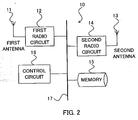
- FIG. 2 is a block diagram of a main part of a radio apparatus of the first embodiment.
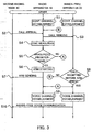
- FIG. 3 is a diagram of a processing sequence and signal flows of the first embodiment of a method for controlling a hands-free system of the present invention.
- FIG. 4 is a diagram of a processing sequence and signal flows of a second embodiment of a method for controlling a hands-free system of the present invention.
- FIG. 5 is a diagram of a processing sequence and signal flows of a third embodiment of a method for controlling a hands-free system of the present invention.
- FIG. 6 is a block diagram of a hands-free apparatus of a fourth embodiment of the invention.
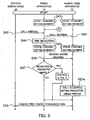
- FIG. 7 is a diagram of a processing sequence and signal flows of the fourth embodiment of a method for controlling a hands-free system of the present invention.
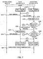
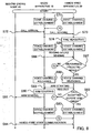
- FIG. 8 is a diagram of a processing sequence and signal flows of a fifth embodiment of a method for controlling a hands-free system of the present invention.
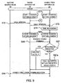
- FIG. 9 is a diagram of a processing sequence and signal flows of a sixth embodiment of a method for controlling a hands-free system of the present invention.
- FIG. 1 is a block diagram of a hands-free system of the first embodiment.
- the hands-free system 1 is formed by a radio apparatus 10 and a hands-free apparatus 20.
- the radio apparatus 10 is used as a first ending node of a communication network 30.
- a second ending node 40 is connected to the communication network 30.
- An example of the second ending node 40 is , though not limited to, a cellular phone.
- the radio apparatus 10 and the hands-free apparatus 20 are connectable to each other by a local radio link, e.g., Bluetooth (TM) or WLAN.
- the radio apparatus 10 may be set either normal, i.e., to be used being held by a human hand, or hands-free.
- the hands-free apparatus 20 has, e.g., a panel on which an operation is performed to accept a call sent from other ending nodes including the second ending node 40, and transferred from the radio apparatus 10 being set hands-free.
- the panel may be physically or virtually (e.g., on a screen) implemented.
- the hands-free apparatus 20 has, e.g., a microphone and a loud speaker to enable voice inputs and outputs in a hands-free manner.
- FIG. 2 is a block diagram of a main part of the radio apparatus 10 shown in FIG. 1 .
- the radio apparatus 10 has a first antenna 11 used for sending and receiving radio signals to and from the communication network 30 (more precisely a radio station belonging thereto). Those radio signals carry data and voice conveyed by the communication network 30.
- the first antenna 11 is connected to a first radio circuit 12 that performs transmission of radio signals including coding, modulation, amplification, and so on, and reception of radio signals including amplification, demodulation, decoding, and so on.
- the radio apparatus 10 has a second antenna 13 used for sending and receiving local radio signals to and from the hands-free apparatus 20.
- Those local radio signals carry data through a control channel established on the local radio link, and carry voice through a voice channel established on the local radio link.
- the second antenna 13 is connected to a second radio circuit 14 that performs transmission of local radio signals including coding, modulation, amplification, and so on, and reception of local radio signals including amplification, demodulation, decoding, and so on.
- the radio apparatus 10 has a memory 15 on which stored is a reply message.
- the reply message is, e.g., "Sorry, I am not available for the time being, such and such".
- the radio apparatus 10 has a control circuit 16 that is connected to the first radio circuit 12, the second radio circuit 14, and the memory 15 via a common bus 17.
- the control circuit 16 is, e.g., a microprocessor unit or a digital signal processor, and performs a hands-free control of the first embodiment.
- FIG. 3 is a diagram of a processing sequence and signal flows among the second ending node 40, the radio apparatus 10, and the hands-free apparatus 20 of the first embodiment.
- the control circuit 16 exchanges data necessary to establish a control channel with the hands-free apparatus 20, according to a specified protocol of the local radio link. Local radio signals carrying those data are sent to and received at the second radio circuit 14 and the second antenna 13. As the result a control channel is established on the local radio link (Step "S1").
- the control circuit 16 sets the radio apparatus 10 hands-free and waits for a call arriving from any other ending node of the communication network 30.
- the control circuit 16 receives a call sent by the second ending node 40 and conveyed by the communication network 30, with the first antenna 11 and the first radio circuit 12 (Step “S2").
- the control circuit 16 sends the call to the hands-free apparatus 20 through the control channel, with the second radio circuit 14 and the second antenna 13 (Step "S3").
- the control circuit 16 measures time after sending the call to the hands-free apparatus 20 (Step "S4").
- the hands-free apparatus 20 requests the radio apparatus 10 to establish a voice channel on the local radio link, through the control channel, when the call is accepted on the hands-free apparatus 20.
- the control circuit 16 is thereby aware if the call has been accepted on the hands-free apparatus 20 or not.
- Step "S6" the control circuit 16 reads the reply message out of the memory 15, and starts to send the reply message to the second ending node (Step "S6", or "ARM STARTING", where "ARM” stands for an automatic reply message), with the first radio circuit 12 and the first antenna 11.
- Step "S7" While the reply message is being sent (Step "S7"), the call has been neither accepted nor rejected yet.
- the control circuit 16 receives a request to establish a voice channel, and is aware that the call has been accepted on the hands-free apparatus 20, as described above.
- the control circuit 16 exchanges data necessary to establish a voice channel with the hands-free apparatus 20, according to a specified protocol of the local radio link.
- Local radio signals carrying those data are sent and received with the second radio circuit 14 and the second antenna 13.
- a voice channel is established (Step "S9").
- the control circuit 16 receives incoming voice messages from the second ending node 40 with the first antenna 11 and the first radio circuit 12, and transfers to the hands-free apparatus 20 through the voice channel with the second radio circuit 14 and the second antenna 13.
- the control circuit 16 receives outgoing voice messages from the hands-free apparatus and sends to the second ending node 40 vice versa.
- a hands-free voice communication is thus conducted between the second ending node 40 and the hands-free system 1 (Step "S10").
- Step "S9" When the call is accepted on the hands-free apparatus 20 before the measured time reaches the predetermined time period ("NO" of Step "S5"), the hands-free apparatus 20 and the radio apparatus 10 establish the voice channel (Step "S9") as described above. This sequence goes through a circled “A” as illustrated in FIG. 3 .
- Step "S8" When the call is not accepted on the hands-free apparatus 20 before sending the reply message ends ("NO" of Step "S8"), the control circuit 16 rejects the call and goes back to the status of waiting for an arriving call before Step "S2". This sequence goes through a circled "B" as illustrated in FIG. 3 .
- a spoken message sent from the second ending node 40 may be recorded and stored on the memory 15 before rejecting the call, in a case where the reply message includes inviting to leave a message.
- the radio apparatus 10 may be set normal before the call is accepted on the hands-free apparatus 20.
- a normal voice communication is conducted while the radio apparatus 10 is being held by a human hand in such a case.
- accepting a call on the hands-free apparatus is allowed not only before starting to send the reply message but also while it is being sent. This advantage makes hands-free systems more convenient and user-friendly than conventional ones.
- FIG. 1 and FIG. 2 will also be referenced as a hands-free system of the second embodiment has the same configuration as the one of the first embodiment shown in FIG. 1 and FIG. 2 .
- a ringing sound is stored on the memory 15 in addition to the reply message described in the first embodiment.
- FIG. 4 is a diagram of a processing sequence and signal flows among the second ending node 40, the radio apparatus 10, and the hands-free apparatus 20 of the second embodiment.
- Step "S41 " Establishing a control channel on the local radio link (Step "S41 "), receiving a call at the radio apparatus 10 (Step “S42”), sending the call to the hands-free apparatus (Step “S43”), and measuring time (Step “S44”) are identical to Steps "S1", “S2", “S3", and “S4", respectively, in FIG. 3 , and a detailed explanation of these steps is omitted.
- Step "S44" While measuring time (Step "S44"), the control circuit 16 exchanges data necessary to establish a voice channel in advance according to a specified protocol, with the hands-free apparatus 20, and establish the voice channel on the local radio link (Step "S45").
- the voice channel established in advance is identical to the voice channel in the first embodiment, and is used to transfer sounds as well as voice messages.
- the control circuit 16 reads the ringing sound out of the memory 15, and sends the sound to the hands-free apparatus 20 through the voice channel, with the second radio circuit 14 and the second antenna 13 (Step "S46").
- the hands-free apparatus 20 rings by reproducing the sound, e.g., from the loud speaker.
- Step "S48” the control circuit 16 releases the voice channel with the hands-free apparatus 20 (Step "S48"). Then the control circuit 16 reads the reply message out of the memory 15, and starts to send the reply message to the second ending node 40 (Step "S49") as at Step "S6" in FIG. 3 .
- Step "S50" Sending the reply message (Step “S50"), accepting the call on the hands-free apparatus 20 (Step “S51 “), establishing the voice channel (Step “S52”), and conducting a hands-free voice communication (Step “S53") are identical to Steps "S7", “S8", “S9", and “S10", respectively, in FIG. 3 , and a detailed explanation of these steps is omitted. It should be noted, though, that Step “S52” is re-establishing the voice channel in the second embodiment.
- Step "S51” When the call is not accepted before sending the reply message ends ("NO" of Step “S51 "), the control circuit 16 rejects the call and goes back to the status of waiting for an arriving call before Step "S42". This sequence goes through a circled “D” as illustrated in FIG. 4 .
- the hands free-apparatus informs of the call arrival by ringing. This advantage helps an earlier acknowledgement of a call arrival and enables a smoother hands-free voice communication.
- FIG. 1 and FIG. 2 will also be referenced as a hands-free system of the third embodiment has the same configuration as the one of the first embodiment shown in FIG. 1 and FIG. 2 .
- a ringing sound is stored on the memory 15 as in the second embodiment.
- FIG. 5 is a diagram of a processing sequence and signal flows among the second ending node 40, the radio apparatus 10, and the hands-free apparatus 20 of the third embodiment. Steps "S41" through “S47” are the same as in FIG. 4 , and that is why the same reference names are given to these steps, a detailed explanation of which is omitted.
- the hands-free apparatus 20 and the radio apparatus 10 maintain the voice channel established at Step "S45” and conduct the hands-free voice communication of Step “S53" using the voice channel.
- the voice channel is not released and is used to transfer voice messages between the radio apparatus and the hands-free apparatus, thus simplifying the sequence in a case where the call is accepted within the predetermined period.
- FIG. 1 will also be referenced since a hands-free system in the fourth embodiment has the same configuration as the one in the first embodiment shown in FIG. 1 .
- the same reference numerals given to the apparatuses, components or circuits in these figures will be used in the following description, and a detailed explanation of these is omitted.
- FIG. 6 is a block diagram of a hands-free apparatus 20 of the fourth embodiment.
- the hands-free apparatus 20 has an antenna 21 used for sending and receiving local radio signals to and from the radio apparatus 10. These local radio signals carry data through a control channel established on the local radio link, and carry voice through a voice channel established on the local radio link.
- the antenna 21 is connected to a radio circuit 22 that performs transmission of local radio signals including coding, modulation, amplification, and so on, and reception of local radio signals including amplification, demodulation, decoding, and so on.
- the hands-free apparatus 20 has an operation device 23 that is, e.g., a panel physically or virtually (e.g., on a screen) implemented, on which an operation is performed to accept a call from other ending nodes including the second ending node 40.
- the hands-free apparatus 20 has, e.g., a microphone and a loud speaker (both are not shown) to enable voice inputs and outputs in a hands-free manner.
- the hands-free apparatus 20 has a hands-free control circuit 24 that is connected to the radio circuit 22 and the operation device 23 via a common bus 25.
- the hands-free apparatus 20 sends and receives local radio signals to and from the radio apparatus 10 with the radio circuit 22 and the antenna 21, and has the radio apparatus 10 send and receive radio signals to and from the communication network 30, as controlled by the hands-free control circuit 24.
- the hands-free control circuit 24 is, e.g., a microprocessor or a digital signal processor, and performs a hands-free control of the fourth embodiment.
- FIG. 7 is a diagram of a processing sequence and signal flows among the second ending node 40, the radio apparatus 10, and the hands-free apparatus 20 in the fourth embodiment.
- the hands-free apparatus 20 exchanges data necessary to establish a control channel with the radio apparatus 10, according to a specified protocol of the local radio link. Local radio signals carrying these data are sent and received with the radio circuit 22 and the antenna 21. As the result a control channel is established on the local radio link (Step "S71 ").
- the radio apparatus 10 sets itself hands-free as described in the first embodiment.
- the radio apparatus 10 receives a call sent by the second ending node 40 and conveyed by the communication network 30 (Step "S72"), and transfers the call to the hands-free apparatus 20 through the control channel (Step "S73").
- the hands-free apparatus 20 receives the call with the antenna 21 and the radio circuit 22.
- the hands-free control circuit 24 measures time after receiving the call (Step "S74"). When a period of the measured time reaches a predetermined time period while the call is not accepted with the operation device 23 ("YES" of Step “S75"), the hands-free control circuit requests the radio apparatus 10 to start to send a reply message to the second ending node 40 (Step "S76"). The radio apparatus 10 then reads the reply message out of its memory and starts to send (Step "S77").
- Step "S78" While the reply message is being sent (Step "S78"), the call has been neither accepted nor rejected yet.
- the hands-free control circuit 24 exchanges data necessary to establish a voice channel with the radio apparatus 10, according to a specified protocol of the local radio link. Local radio signals carrying those data are sent and received with the radio circuit 22 and the antenna 21. As the result a voice channel is established (Step "S80").
- a hands-free voice communication is conducted between the second ending node 40 and the hands-free system 1 (Step "S81 ") as described in the first embodiment.
- Step "S80" When the call is accepted with the operation device 23 before the measured time reaches the predetermined time period ("NO" of Step “S75"), the hands-free apparatus 20 and the radio apparatus 10 establish the voice channel (Step "S80") as described above. This sequence goes through a circled “E” as illustrated in FIG. 3 .
- the hands-free control circuit 24 requests the radio apparatus 10 to reject the call and goes back to the status of waiting for an arriving call before Step "S72". This sequence goes through a circled "F” as illustrated in FIG. 7 .
- the hands-free system may be controlled by the hands-free apparatus and obtains the same effect as in the first embodiment.
- FIG. 1 and FIG. 6 will also be referenced as a hands-free system in the fifth embodiment has the same configuration as the one in the fourth embodiment shown in FIG. 1 and FIG. 6 .
- the same reference numerals given to the apparatuses, components or circuits in these figures will be used in the following description, and a detailed explanation of these is omitted.
- FIG. 8 is a diagram of a processing sequence and signal flows among the second ending node 40, the radio apparatus 10, and the hands-free apparatus 20 of the fifth embodiment. Steps "S71" through “S74" are the same as those in FIG. 7 , and a detailed explanation of these steps is omitted.
- the hands-free control circuit 24 While measuring time (Step "S74"), exchanges data necessary to establish a voice channel in advance according to a specified protocol, with the radio apparatus 10, and establish the voice channel on the local radio link (Step "S85").
- the voice channel established in advance is identical to the voice channel in the fourth embodiment, and is used to transfer sounds as well as voice messages.
- the radio apparatus 10 sends a ringing sound read out of its memory through the voice channel to the hands-free apparatus 20 (Step "S86").
- the ringing sound is received by the antenna 21 and the radio circuit 22, and the hands-free control circuit controls reproducing the ringing sound by, e.g., driving the loud speaker.
- the hands-free control circuit 24 releases the voice channel with the radio apparatus 10 (Step "S88"). Then the hands-free control circuit 24 requests the radio apparatus 10 to start to send a reply message to the second ending node 40 (Step "S89”). The radio apparatus 10 then reads the reply message out of its memory and starts to send (Step "S90").
- the hands-free control circuit 24 requests the radio apparatus 10 to reject the call and goes back to the status of waiting for an arriving call before Step "S72". This sequence goes through a circled "H” as illustrated in FIG. 8 .
- the hands-free system may be controlled by the hands-free apparatus and obtains the same effect as in the second embodiment.
- FIG. 9 A sixth embodiment of the present invention will now be described with reference to FIG. 9 .
- FIG. 1 and FIG. 6 will also be referenced since a hands-free system in the sixth embodiment has the same configuration as the one in the fourth embodiment shown in FIG. 1 and FIG. 6 .
- the same reference numerals given to the apparatuses, components or circuits in these figures will be used in the following description, and a detailed explanation of these is omitted.
- FIG. 9 is a diagram of a processing sequence and signal flows among the second ending node 40, the radio apparatus 10, and the hands-free apparatus 20 of the third embodiment. Steps "S71" through “S74", “S85”, “S86”, “YES” of "S87", “S88” through “S93” and “S94” are the same as those in FIG. 8 , and a detailed explanation of these steps is omitted.
- the hands-free apparatus 20 and the radio apparatus 10 maintain the voice channel established at Step "S85” and conduct the hands-free voice communication of Step “S94" using the voice channel.
- the hands-free system may be controlled by the hands-free apparatus and obtains the same effect as in the third embodiment.
Landscapes
- Engineering & Computer Science (AREA)
- Signal Processing (AREA)
- Telephone Function (AREA)
- Mobile Radio Communication Systems (AREA)
Claims (4)
- Funkgerät (10), das mit einer Funkstation über eine erste Antenne (11) verbindbar ist und mit einem Freihandgerät (20) über eine zweite Antenne (13) verbindbar ist, wobei das Funkgerät (10) umfasst:eine erste Funkschaltung (12), die konfiguriert ist, Funksignale zu und von der Funkstation über die erste Antenne (11) zu senden und zu empfangen;eine zweite Funkschaltung (14), eine Vielzahl von lokalen Funksignalen zu und von dem Freihandgerät (20) über die zweite Antenne (13) sendet und empfängt; undein Steuergerät (16), das konfiguriert ist, das Funkgerät zu steuern, dadurch gekennzeichnet, dass das Steuergerät (16) angeordnet ist, um(a) einen Steuerkanal mit dem Freihandgerät (20) über die zweite Funkschaltung (14) und die zweite Antenne (13) herzustellen und in einen Freihandmodus umzuschalten,(b) einen eingehenden Anruf an das Freihandgerät (20) über den Steuerkanal zu senden, falls der eingehende Anruf detektiert wird, während der Freihandmodus eingestellt ist,(c) eine Zeit zu messen, die nach einem Senden des eingehenden Anrufes an das Freihandgerät (20) verstrichen ist,(d) den eingehenden Anruf automatisch zu beantworten und eine Sprachnachricht aufzuzeichnen, die von der Funkstation übertragen wird, falls die gemessene Zeit einen vorbestimmten Zeitraum erreicht, während kein Signal zum Beantworten des eingehenden Anrufes von dem Freihandgerät (20) über den Steuerkanal empfangen wird,(e) einen Sprachkanal mit dem Freihandgerät (20) über die zweite Funkschaltung (14) und die zweite Antenne (13) herzustellen, falls ein Signal zum Beantworten des eingehenden Anrufes von dem Freihandgerät (20) über den Steuerkanal empfangen wird, während die Sprachnachricht aufgezeichnet wird, und(f) Übertragen einer Sprachnachricht von der Funkstation zu dem Freihandgerät (20) und einer Sprachnachricht von dem Freihandgerät (20) zu der Funkstation, nachdem das Signal zum Beantworten des eingehenden Anrufes von dem Freihandgerät (20) empfangen wird.
- Funkgerät (10) nach Anspruch 1, weiter mit:einem Speicher (15), der eine Antwortnachricht zum Auffordern eines Anrufers speichert, eine Sprachnachricht zu hinterlassen; unddas Steuergerät (16) konfiguriert ist, die Antwortnachricht an die Funkstation über die erste Funkschaltung (12) und die erste Antenne (11) zu senden, nachdem der eingehende Anruf automatisch beantwortet ist.
- Funkgerät (10), das mit einer Funkstation über eine erste Antenne (11) verbindbar ist und mit einem Freihandgerät (20) über eine zweite Antenne (13) verbindbar ist, wobei das Funkgerät (10) umfasst:einen Speicher (15), der konfiguriert ist, einen Klingelton zu speichern;eine erste Funkschaltung (12), die konfiguriert ist, Funksignale zu und von der Funkstation über die erste Antenne (11) zu senden und zu empfangen;eine zweite Funkschaltung (14), die konfiguriert ist, eine Vielzahl von lokalen Funksignalen zu und von dem Freihandgerät (20) über die zweite Antenne (13) zu senden und zu empfangen; undein Steuergerät (16), das konfiguriert ist, das Funkgerät (10) zu steuern, dadurch gekennzeichnet, dass das Steuergerät (16) angeordnet ist(a) einen Steuerkanal mit dem Freihandgerät (20) über die zweite Funkschaltung (14) und die zweite Antenne (13) herzustellen und in einen Freihandmodus umzuschalten,(b) einen eingehenden Anruf an das Freihandgerät (20) über den Steuerkanal zu senden, falls der eingehende Anruf detektiert wird, während der Freihandmodus eingestellt ist,(c) einen Sprachkanal mit dem Freihandgerät (20) über die zweite Funkschaltung (14) und die zweite Antenne (13) herzustellen, nachdem einem Senden des eingehenden Anruf an das Freihandgerät (20),(d) eine Zeit nach einem Senden des eingehenden Anrufes an das Freihandgerät (20) zu senden,(e) den Sprachkanal freizugeben, den eingehenden Anruf automatisch zu beantworten und eine Sprachnachricht aufzuzeichnen, die von der Funkstation übertragen wird, falls die gemessene Zeit einen vorbestimmten Zeitraum erreicht, während kein Signal zum Beantworten des eingehenden Anrufes von dem Freihandgerät (20) über den Steuerkanal empfangen wird,(f) den Sprachkanal mit dem Freihandgerät (20) über die zweite Funkschaltung (14) und die zweite Antenne (13) wieder herzustellen, falls ein Signal zum Beantworten des eingehenden Anrufes von dem Freihandgerät (20) über den Steuerkanal empfangen wird, während einem Aufzeichnen der Sprachnachricht, und(g) eine Sprachnachricht von der Funkstation an das Freihandgerät (20) und eine Sprachnachricht von dem Freihandgerät (20) an die Funkstation zu übertragen, nachdem das Signal zum Beantworten des eingehenden Anrufes von dem Freihandgerät (20) empfangen ist.
- Funkgerät (10) nach Anspruch 3, wobei der Speicher (15) weiter eine Antwortnachricht zum Auffordern eines Anrufers speichert, eine Sprachnachricht zu hinterlassen und das Steuergerät (16) angeordnet ist, die Antwortnachricht an die Funkstation über die erste Funkschaltung (12) und die erste Antenne (11) zu senden, nachdem der eingehende Anruf automatisch beantwortet ist.
Applications Claiming Priority (2)
| Application Number | Priority Date | Filing Date | Title |
|---|---|---|---|
| JP2004113012 | 2004-04-07 | ||
| JP2004113012A JP4319573B2 (ja) | 2004-04-07 | 2004-04-07 | 移動通信端末装置 |
Publications (2)
| Publication Number | Publication Date |
|---|---|
| EP1585294A1 EP1585294A1 (de) | 2005-10-12 |
| EP1585294B1 true EP1585294B1 (de) | 2009-01-14 |
Family
ID=34909504
Family Applications (1)
| Application Number | Title | Priority Date | Filing Date |
|---|---|---|---|
| EP04255964A Expired - Lifetime EP1585294B1 (de) | 2004-04-07 | 2004-09-29 | Verfahren zum Steuern einer Freisprecheinrichtung und dazugehörige Freisprecheinrichtung |
Country Status (4)
| Country | Link |
|---|---|
| US (1) | US7720512B2 (de) |
| EP (1) | EP1585294B1 (de) |
| JP (1) | JP4319573B2 (de) |
| DE (1) | DE602004019046D1 (de) |
Families Citing this family (12)
| Publication number | Priority date | Publication date | Assignee | Title |
|---|---|---|---|---|
| JP4225222B2 (ja) * | 2004-03-15 | 2009-02-18 | 株式会社デンソー | 車載ハンズフリー装置 |
| JP3842793B2 (ja) * | 2004-04-07 | 2006-11-08 | 株式会社東芝 | 移動通信端末装置 |
| US7515910B2 (en) * | 2005-09-26 | 2009-04-07 | Motorola, Inc. | Cellular/WLAN hybrid-terminal handover techniques |
| JP4439476B2 (ja) * | 2006-02-08 | 2010-03-24 | 株式会社東芝 | データ転送装置および携帯電話 |
| US20080268780A1 (en) * | 2007-04-27 | 2008-10-30 | Werner Jeffry W | Wireless notification apparatus and method |
| US20110059731A1 (en) * | 2009-09-04 | 2011-03-10 | George Gregory Schivley | Techniques for discouraging cell phone usage while driving a vehicle |
| US9241851B2 (en) | 2011-10-03 | 2016-01-26 | University Of South Florida | Hands-free user interface devices |
| DE112014000709B4 (de) * | 2013-02-07 | 2021-12-30 | Apple Inc. | Verfahren und vorrichtung zum betrieb eines sprachtriggers für einen digitalen assistenten |
| AU2021202255B9 (en) * | 2013-02-07 | 2022-06-09 | Apple Inc. | Voice trigger for a digital assistant |
| JP6319722B2 (ja) * | 2014-02-19 | 2018-05-09 | アルプス電気株式会社 | ハンズフリー機器 |
| US9924011B2 (en) * | 2014-08-29 | 2018-03-20 | Hyundai Motor Company | Manual bluetooth hands free transfer mode |
| CN105516439A (zh) * | 2014-09-23 | 2016-04-20 | 中兴通讯股份有限公司 | 一种电话接听、挂断方法及终端 |
Family Cites Families (22)
| Publication number | Priority date | Publication date | Assignee | Title |
|---|---|---|---|---|
| JPH054592Y2 (de) | 1987-07-13 | 1993-02-04 | ||
| US4881259A (en) * | 1989-01-06 | 1989-11-14 | Dynascan Corporation | Answering machine with cordless telephone |
| JPH07322350A (ja) * | 1994-05-23 | 1995-12-08 | Nec Corp | 親機と子機から成る携帯用移動電話機 |
| JP3474945B2 (ja) | 1994-08-31 | 2003-12-08 | 三洋電機株式会社 | コードレス電話装置 |
| JPH0984141A (ja) * | 1995-09-18 | 1997-03-28 | Casio Comput Co Ltd | 着信呼出装置 |
| US5966656A (en) * | 1997-03-11 | 1999-10-12 | Motorola, Inc. | Method and apparatus for displaying signal information in a radio communication device |
| JPH114190A (ja) * | 1997-06-11 | 1999-01-06 | Oki Electric Ind Co Ltd | 車載用携帯電話システム |
| KR100247199B1 (ko) * | 1997-11-06 | 2000-10-02 | 윤종용 | 이동통신전화기장치및통화방법 |
| GB2337666B (en) * | 1998-05-18 | 2000-11-08 | Matsushita Comm Ind Uk Ltd | Call handling in mobile telephones |
| JP2002526985A (ja) * | 1998-09-25 | 2002-08-20 | コーニンクレッカ フィリップス エレクトロニクス エヌ ヴィ | 無音応答機能を備える移動電話 |
| WO2001099392A1 (en) * | 2000-06-21 | 2001-12-27 | Seiko Epson Corporation | Mobile telephone and radio communication device cooperatively processing incoming call |
| JP3599097B2 (ja) * | 2000-10-10 | 2004-12-08 | 日本電気株式会社 | 周辺装置による携帯通信装置の呼出方法、それを用いた携帯通信装置および周辺装置 |
| JP2003051896A (ja) | 2001-05-28 | 2003-02-21 | Matsushita Electric Ind Co Ltd | 車載用通信装置及びその方法 |
| US7233808B2 (en) * | 2001-09-05 | 2007-06-19 | Agere Systems Inc. | Smart BLUETOOTH interface gateway to mate a non-BLUETOOTH wireless device with a BLUETOOTH headset |
| US6807433B2 (en) * | 2002-03-18 | 2004-10-19 | Kabushiki Kaisha Toshiba | Mobile communication terminal with unanswered incoming-call notifying function |
| US7110798B2 (en) * | 2002-05-09 | 2006-09-19 | Shary Nassimi | Wireless headset |
| DE10226425A1 (de) * | 2002-06-13 | 2003-12-24 | Bosch Gmbh Robert | Verfahren zur Unterstützung des Fahrers bei der Entgegennahme von Anrufen sowie Einrichtung hierzu |
| JP3707462B2 (ja) * | 2002-09-18 | 2005-10-19 | 日本電気株式会社 | 携帯電話機及びそれに用いるローカル無線通信方法並びにそのプログラム |
| US7027842B2 (en) * | 2002-09-24 | 2006-04-11 | Bellsouth Intellectual Property Corporation | Apparatus and method for providing hands-free operation of a device |
| US7142814B2 (en) * | 2002-12-11 | 2006-11-28 | Shary Nassimi | Automatic Bluetooth inquiry mode headset |
| US7953454B2 (en) * | 2003-03-21 | 2011-05-31 | Sony Ericsson Mobile Communications Ab | Wireless hands-free system with silent user signaling |
| JP3842793B2 (ja) | 2004-04-07 | 2006-11-08 | 株式会社東芝 | 移動通信端末装置 |
-
2004
- 2004-04-07 JP JP2004113012A patent/JP4319573B2/ja not_active Expired - Fee Related
- 2004-09-29 DE DE602004019046T patent/DE602004019046D1/de not_active Expired - Lifetime
- 2004-09-29 EP EP04255964A patent/EP1585294B1/de not_active Expired - Lifetime
- 2004-10-01 US US10/954,493 patent/US7720512B2/en not_active Expired - Fee Related
Also Published As
| Publication number | Publication date |
|---|---|
| JP4319573B2 (ja) | 2009-08-26 |
| US7720512B2 (en) | 2010-05-18 |
| JP2005303435A (ja) | 2005-10-27 |
| EP1585294A1 (de) | 2005-10-12 |
| US20050113149A1 (en) | 2005-05-26 |
| DE602004019046D1 (de) | 2009-03-05 |
Similar Documents
| Publication | Publication Date | Title |
|---|---|---|
| EP1585294B1 (de) | Verfahren zum Steuern einer Freisprecheinrichtung und dazugehörige Freisprecheinrichtung | |
| US7336933B2 (en) | Method of maintaining communication with a device | |
| KR100712415B1 (ko) | 통신 시스템의 콜백 방법 및 단말기 | |
| JP3224365B2 (ja) | 無線通信方法および無線通信システム | |
| JP3099710B2 (ja) | デジタル無線電話システム | |
| US7496047B2 (en) | Communication terminal, operating equipment, communication system, and communication control method | |
| JPH1198256A (ja) | 通信端末機及びディジタル交換機ならびに発信者情報転送システム | |
| KR100800763B1 (ko) | 이동 통신 단말의 음성 사서함 연결 방법 | |
| JP3022881B1 (ja) | 通信回線確保システム及びその方法 | |
| JP2001008259A (ja) | コールバック通信制御方法とそのシステム | |
| JP4183147B2 (ja) | 通信端末、制御方法 | |
| JP3639438B2 (ja) | 携帯電話機における応答保留方法 | |
| JP3141750B2 (ja) | ボタン電話装置 | |
| JP2531340B2 (ja) | 無線電話装置 | |
| JP4581791B2 (ja) | 電話システムおよび無線基地局装置 | |
| JP2002044243A (ja) | ボタン電話装置 | |
| JP3009308B2 (ja) | マルチゾーンコードレスシステムにおける使用すべき接続装置の決定方法及びマルチゾーンコードレスシステム | |
| JP3225807B2 (ja) | コードレス着信制御方法及びその装置 | |
| JPH05122304A (ja) | コードレスisdn端末 | |
| JPH09149458A (ja) | 移動型電話機およびこれを有するメールシステム | |
| JPH06225357A (ja) | 通信システム | |
| JP2002044242A (ja) | ボタン電話装置 | |
| JPH05160785A (ja) | 無線電話装置 | |
| JPH10294963A (ja) | 携帯電話のマルチベンダ間接続システム | |
| JPH08237749A (ja) | 無線電話装置および無線電話システム装置 |
Legal Events
| Date | Code | Title | Description |
|---|---|---|---|
| PUAI | Public reference made under article 153(3) epc to a published international application that has entered the european phase |
Free format text: ORIGINAL CODE: 0009012 |
|
| 17P | Request for examination filed |
Effective date: 20041008 |
|
| AK | Designated contracting states |
Kind code of ref document: A1 Designated state(s): AT BE BG CH CY CZ DE DK EE ES FI FR GB GR HU IE IT LI LU MC NL PL PT RO SE SI SK TR |
|
| AX | Request for extension of the european patent |
Extension state: AL HR LT LV MK |
|
| AKX | Designation fees paid |
Designated state(s): DE FR GB |
|
| R17C | First examination report despatched (corrected) |
Effective date: 20060321 |
|
| GRAP | Despatch of communication of intention to grant a patent |
Free format text: ORIGINAL CODE: EPIDOSNIGR1 |
|
| GRAS | Grant fee paid |
Free format text: ORIGINAL CODE: EPIDOSNIGR3 |
|
| GRAA | (expected) grant |
Free format text: ORIGINAL CODE: 0009210 |
|
| AK | Designated contracting states |
Kind code of ref document: B1 Designated state(s): DE FR GB |
|
| REG | Reference to a national code |
Ref country code: GB Ref legal event code: FG4D |
|
| REF | Corresponds to: |
Ref document number: 602004019046 Country of ref document: DE Date of ref document: 20090305 Kind code of ref document: P |
|
| PLBE | No opposition filed within time limit |
Free format text: ORIGINAL CODE: 0009261 |
|
| STAA | Information on the status of an ep patent application or granted ep patent |
Free format text: STATUS: NO OPPOSITION FILED WITHIN TIME LIMIT |
|
| 26N | No opposition filed |
Effective date: 20091015 |
|
| REG | Reference to a national code |
Ref country code: GB Ref legal event code: 732E Free format text: REGISTERED BETWEEN 20110224 AND 20110302 |
|
| REG | Reference to a national code |
Ref country code: FR Ref legal event code: TP |
|
| REG | Reference to a national code |
Ref country code: DE Ref legal event code: R082 Ref document number: 602004019046 Country of ref document: DE Representative=s name: HOFFMANN - EITLE, DE |
|
| REG | Reference to a national code |
Ref country code: DE Ref legal event code: R081 Ref document number: 602004019046 Country of ref document: DE Owner name: FUJITSU MOBILE COMMUNICATIONS LTD., JP Free format text: FORMER OWNER: KABUSHIKI KAISHA TOSHIBA, TOKYO, JP Effective date: 20111213 Ref country code: DE Ref legal event code: R082 Ref document number: 602004019046 Country of ref document: DE Representative=s name: HOFFMANN - EITLE, DE Effective date: 20111213 Ref country code: DE Ref legal event code: R082 Ref document number: 602004019046 Country of ref document: DE Representative=s name: HOFFMANN - EITLE PATENT- UND RECHTSANWAELTE PA, DE Effective date: 20111213 |
|
| REG | Reference to a national code |
Ref country code: DE Ref legal event code: R082 Ref document number: 602004019046 Country of ref document: DE Representative=s name: HOFFMANN - EITLE, DE |
|
| REG | Reference to a national code |
Ref country code: FR Ref legal event code: CD Owner name: FUJITSU TOSHIBA MOBILE COMMUNICATIONS LIMITED, JP Effective date: 20130128 |
|
| REG | Reference to a national code |
Ref country code: DE Ref legal event code: R081 Ref document number: 602004019046 Country of ref document: DE Owner name: FUJITSU MOBILE COMMUNICATIONS LTD., JP Free format text: FORMER OWNER: FUJITSU TOSHIBA MOBILE COMMUNICATIONS LTD., KAWASAKI-SHI, JP Effective date: 20130123 Ref country code: DE Ref legal event code: R082 Ref document number: 602004019046 Country of ref document: DE Representative=s name: HOFFMANN - EITLE, DE Effective date: 20130123 Ref country code: DE Ref legal event code: R081 Ref document number: 602004019046 Country of ref document: DE Owner name: FUJITSU MOBILE COMMUNICATIONS LTD., JP Free format text: FORMER OWNER: FUJITSU TOSHIBA MOBILE COMMUNICATIONS LTD., KAWASAKI-SHI, KANAGAWA, JP Effective date: 20130123 Ref country code: DE Ref legal event code: R082 Ref document number: 602004019046 Country of ref document: DE Representative=s name: HOFFMANN - EITLE PATENT- UND RECHTSANWAELTE PA, DE Effective date: 20130123 |
|
| REG | Reference to a national code |
Ref country code: FR Ref legal event code: PLFP Year of fee payment: 13 |
|
| REG | Reference to a national code |
Ref country code: FR Ref legal event code: PLFP Year of fee payment: 14 |
|
| REG | Reference to a national code |
Ref country code: FR Ref legal event code: PLFP Year of fee payment: 15 |
|
| REG | Reference to a national code |
Ref country code: DE Ref legal event code: R082 Ref document number: 602004019046 Country of ref document: DE Representative=s name: HOFFMANN - EITLE PATENT- UND RECHTSANWAELTE PA, DE Ref country code: DE Ref legal event code: R081 Ref document number: 602004019046 Country of ref document: DE Owner name: FUJITSU CONNECTED TECHNOLOGIES LIMITED, KAWASA, JP Free format text: FORMER OWNER: FUJITSU MOBILE COMMUNICATIONS LTD., KAWASAKI-SHI, JP |
|
| REG | Reference to a national code |
Ref country code: GB Ref legal event code: 732E Free format text: REGISTERED BETWEEN 20190214 AND 20190221 |
|
| PGFP | Annual fee paid to national office [announced via postgrant information from national office to epo] |
Ref country code: FR Payment date: 20190815 Year of fee payment: 16 Ref country code: DE Payment date: 20190917 Year of fee payment: 16 |
|
| PGFP | Annual fee paid to national office [announced via postgrant information from national office to epo] |
Ref country code: GB Payment date: 20190926 Year of fee payment: 16 |
|
| REG | Reference to a national code |
Ref country code: DE Ref legal event code: R119 Ref document number: 602004019046 Country of ref document: DE |
|
| GBPC | Gb: european patent ceased through non-payment of renewal fee |
Effective date: 20200929 |
|
| PG25 | Lapsed in a contracting state [announced via postgrant information from national office to epo] |
Ref country code: FR Free format text: LAPSE BECAUSE OF NON-PAYMENT OF DUE FEES Effective date: 20200930 Ref country code: DE Free format text: LAPSE BECAUSE OF NON-PAYMENT OF DUE FEES Effective date: 20210401 |
|
| PG25 | Lapsed in a contracting state [announced via postgrant information from national office to epo] |
Ref country code: GB Free format text: LAPSE BECAUSE OF NON-PAYMENT OF DUE FEES Effective date: 20200929 |