EP1585294B1 - Method for controlling a hands-free apparatus and corresponding hands-free apparatus - Google Patents
Method for controlling a hands-free apparatus and corresponding hands-free apparatus Download PDFInfo
- Publication number
- EP1585294B1 EP1585294B1 EP04255964A EP04255964A EP1585294B1 EP 1585294 B1 EP1585294 B1 EP 1585294B1 EP 04255964 A EP04255964 A EP 04255964A EP 04255964 A EP04255964 A EP 04255964A EP 1585294 B1 EP1585294 B1 EP 1585294B1
- Authority
- EP
- European Patent Office
- Prior art keywords
- hands
- radio
- free
- antenna
- free apparatus
- Prior art date
- Legal status (The legal status is an assumption and is not a legal conclusion. Google has not performed a legal analysis and makes no representation as to the accuracy of the status listed.)
- Expired - Lifetime
Links
- 238000000034 method Methods 0.000 title description 11
- 238000012546 transfer Methods 0.000 claims description 7
- 238000004891 communication Methods 0.000 description 21
- 238000010586 diagram Methods 0.000 description 18
- 238000012545 processing Methods 0.000 description 12
- 230000003321 amplification Effects 0.000 description 6
- 238000003199 nucleic acid amplification method Methods 0.000 description 6
- 230000000694 effects Effects 0.000 description 4
- 230000005540 biological transmission Effects 0.000 description 3
- 230000001413 cellular effect Effects 0.000 description 2
- 238000007796 conventional method Methods 0.000 description 1
- 230000003111 delayed effect Effects 0.000 description 1
- 230000006870 function Effects 0.000 description 1
- 238000005259 measurement Methods 0.000 description 1
- 230000003252 repetitive effect Effects 0.000 description 1
Images


Classifications
-
- H—ELECTRICITY
- H04—ELECTRIC COMMUNICATION TECHNIQUE
- H04M—TELEPHONIC COMMUNICATION
- H04M1/00—Substation equipment, e.g. for use by subscribers
- H04M1/60—Substation equipment, e.g. for use by subscribers including speech amplifiers
- H04M1/6033—Substation equipment, e.g. for use by subscribers including speech amplifiers for providing handsfree use or a loudspeaker mode in telephone sets
- H04M1/6041—Portable telephones adapted for handsfree use
- H04M1/6075—Portable telephones adapted for handsfree use adapted for handsfree use in a vehicle
Definitions
- the present invention relates to a method for controlling a hands-free system, a radio apparatus, and a hands-free apparatus.
- Radio communications are now widely used, including on moving vehicles or in any busy situations.
- Hands-free systems are used for such kinds of radio communications to assure traffic safety or any kind of conveniences.
- a hands-free system is formed by a radio apparatus, e.g., a cellular phone, and a hands-free apparatus,
- a radio apparatus and a hands-free apparatus are linked to each other by a local radio link to form a hands-free system, provided that they are capable of sending and receiving radio signals through the link.
- a local radio link examples include Bluetooth (TM) and a wireless local area network (WLAN), and particularly in the Bluetooth specifications there is provided a standardized hands-free profile to support such kinds of applications.
- a hands-free system formed by a radio apparatus and a hands-free apparatus.
- the hands-free apparatus has a microphone, a loud speaker, and an operation panel.
- the hands-free apparatus is connectable to the radio apparatus by a local radio link, and the radio apparatus may be set normal, i.e., to be used while being held by a human hand, or hands-free.
- a control channel is established on the local radio link.
- the radio apparatus is used as an ending node of a communication network.
- An incoming phone call received at the radio apparatus is transferred to the hands-free apparatus through the control channel.
- the call may be accepted on the hands-free apparatus, i.e., by operating the operation panel thereof.
- a voice channel is established on the local radio link to enable a voice communication in a hands-free manner, using the microphone and the loud speaker of the hands-free apparatus.
- the radio apparatus When a call arrives at the radio apparatus from another ending node of the communication network, i.e., the other party on the phone, the call is transferred from the radio apparatus to the hands-free apparatus through the control channel. If the call is not accepted on the hands-free apparatus during a predetermined period of time, the radio apparatus reads out a reply message, like "Sorry, I am not available for the time being", stored in a built-in memory and sends the reply message to the other party, as one of usual functions of radio apparatuses.
- a reply message like "Sorry, I am not available for the time being"
- Accepting the call on the hands-free apparatus is usually ineffective after sending the reply message begins. That is inconvenient, in a case where an operation to accept the call has to be delayed due to an instantaneous traffic situation or some other reasons although such an operation has been intended.
- Vehicular phone systems were improved to alleviate a danger when a call arrives at a radio apparatus included in the system, and the improved systems are disclosed in the Japanese published patent applications, e.g., H11-4190 and 2003-51896 , the English versions of which are available on the Japan Patent Office website.
- the former one of those conventional systems determines if the vehicle is moving or not, when a call from another party arrives at the radio apparatus, based on the velocity data obtained by a velocity measurement unit on board.
- a reply message is sent back, saying that the call cannot be accepted since the vehicle is moving, and a spoken message of the other party is recorded, if any.
- the latter one sends a reply message to the other party including vehicular status in addition to the information if it is moving or not at the time when the call arrives at the radio apparatus. That may help not to receive repetitive calls from the other party, who understands the vehicular status well due to the contents of the reply message.
- WO 9960765 discloses a system for controlling a mobile telephone in which a prerecorded reply message is sent after a predetermined time lapse, if a call is not accepted by the mobile telephone. The call can also be accepted subsequently, while the prerecorded message is playing.
- an advantage of the present invention is to provide a method for controlling a hands-free system that enables accepting a call by operating the hands-free apparatus, even after sending a reply message begins.
- a radio apparatus connectable to a radio station via a first antenna and connectable to a hands-free apparatus via a second antenna
- the radio apparatus comprises a first radio circuit configured to send and receive radio signals to and from the radio station via the first antenna; a second radio circuit send and receive a plurality of local radio signals to and from the hands-free apparatus via the second antenna; and a controller configured to control the radio apparatus, wherein the controller is arranged to (a) establish a control channel with the hands-free apparatus via the second radio circuit and the second antenna, and switch to hands-free mode, (b) send an incoming call to the hands-free apparatus through the control channel if the incoming call is detected while the hands-free mode is being set, (c) measure time elapsed after sending the incoming call to the hands-free apparatus, (d) reply to the incoming call automatically and record a voice message transmitted from the radio station if the measured time reaches a predetermined time period while no signal
- the invention also extends to a radio apparatus connectable to a radio station via a first antenna and connectable to a hands-free apparatus via a second antenna, characterized in that the radio apparatus comprises: a memory configured to store a ringing sound; a first radio circuit configured to send and receive radio signals to and from the radio station via the first antenna; a second radio circuit configured to send and receive a plurality of local radio signals to and from the hands-free apparatus via the second antenna; and a controller configured to control the radio apparatus, wherein the controller is arranged to (a) establish a control channel with the hands-free apparatus via the second radio circuit and the second antenna, and switch to hands-free mode, (b) send an incoming call to the hands-free apparatus through the control channel if the incoming call is detected while the hands-free mode is being set, (c) establish a voice channel with the hands-free apparatus via the second radio circuit and the second antenna after sending the incoming call to the hands-free apparatus, (d) measure time after sending the incoming call to the hands-free apparatus
- accepting a call on the hands-free apparatus is allowed not only before starting to send the reply message but also while it is being sent.
- the sequence to accept the call and start a hands-free voice communication thereby becomes more flexible.
- FIG. 1 is a block diagram of a first embodiment of a hands-free system of the present invention.
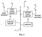
- FIG. 2 is a block diagram of a main part of a radio apparatus of the first embodiment.
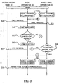
- FIG. 3 is a diagram of a processing sequence and signal flows of the first embodiment of a method for controlling a hands-free system of the present invention.
- FIG. 4 is a diagram of a processing sequence and signal flows of a second embodiment of a method for controlling a hands-free system of the present invention.
- FIG. 5 is a diagram of a processing sequence and signal flows of a third embodiment of a method for controlling a hands-free system of the present invention.
- FIG. 6 is a block diagram of a hands-free apparatus of a fourth embodiment of the invention.
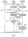
- FIG. 7 is a diagram of a processing sequence and signal flows of the fourth embodiment of a method for controlling a hands-free system of the present invention.
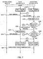
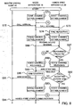
- FIG. 8 is a diagram of a processing sequence and signal flows of a fifth embodiment of a method for controlling a hands-free system of the present invention.
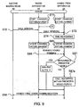
- FIG. 9 is a diagram of a processing sequence and signal flows of a sixth embodiment of a method for controlling a hands-free system of the present invention.
- FIG. 1 is a block diagram of a hands-free system of the first embodiment.
- the hands-free system 1 is formed by a radio apparatus 10 and a hands-free apparatus 20.
- the radio apparatus 10 is used as a first ending node of a communication network 30.
- a second ending node 40 is connected to the communication network 30.
- An example of the second ending node 40 is , though not limited to, a cellular phone.
- the radio apparatus 10 and the hands-free apparatus 20 are connectable to each other by a local radio link, e.g., Bluetooth (TM) or WLAN.
- the radio apparatus 10 may be set either normal, i.e., to be used being held by a human hand, or hands-free.
- the hands-free apparatus 20 has, e.g., a panel on which an operation is performed to accept a call sent from other ending nodes including the second ending node 40, and transferred from the radio apparatus 10 being set hands-free.
- the panel may be physically or virtually (e.g., on a screen) implemented.
- the hands-free apparatus 20 has, e.g., a microphone and a loud speaker to enable voice inputs and outputs in a hands-free manner.
- FIG. 2 is a block diagram of a main part of the radio apparatus 10 shown in FIG. 1 .
- the radio apparatus 10 has a first antenna 11 used for sending and receiving radio signals to and from the communication network 30 (more precisely a radio station belonging thereto). Those radio signals carry data and voice conveyed by the communication network 30.
- the first antenna 11 is connected to a first radio circuit 12 that performs transmission of radio signals including coding, modulation, amplification, and so on, and reception of radio signals including amplification, demodulation, decoding, and so on.
- the radio apparatus 10 has a second antenna 13 used for sending and receiving local radio signals to and from the hands-free apparatus 20.
- Those local radio signals carry data through a control channel established on the local radio link, and carry voice through a voice channel established on the local radio link.
- the second antenna 13 is connected to a second radio circuit 14 that performs transmission of local radio signals including coding, modulation, amplification, and so on, and reception of local radio signals including amplification, demodulation, decoding, and so on.
- the radio apparatus 10 has a memory 15 on which stored is a reply message.
- the reply message is, e.g., "Sorry, I am not available for the time being, such and such".
- the radio apparatus 10 has a control circuit 16 that is connected to the first radio circuit 12, the second radio circuit 14, and the memory 15 via a common bus 17.
- the control circuit 16 is, e.g., a microprocessor unit or a digital signal processor, and performs a hands-free control of the first embodiment.
- FIG. 3 is a diagram of a processing sequence and signal flows among the second ending node 40, the radio apparatus 10, and the hands-free apparatus 20 of the first embodiment.
- the control circuit 16 exchanges data necessary to establish a control channel with the hands-free apparatus 20, according to a specified protocol of the local radio link. Local radio signals carrying those data are sent to and received at the second radio circuit 14 and the second antenna 13. As the result a control channel is established on the local radio link (Step "S1").
- the control circuit 16 sets the radio apparatus 10 hands-free and waits for a call arriving from any other ending node of the communication network 30.
- the control circuit 16 receives a call sent by the second ending node 40 and conveyed by the communication network 30, with the first antenna 11 and the first radio circuit 12 (Step “S2").
- the control circuit 16 sends the call to the hands-free apparatus 20 through the control channel, with the second radio circuit 14 and the second antenna 13 (Step "S3").
- the control circuit 16 measures time after sending the call to the hands-free apparatus 20 (Step "S4").
- the hands-free apparatus 20 requests the radio apparatus 10 to establish a voice channel on the local radio link, through the control channel, when the call is accepted on the hands-free apparatus 20.
- the control circuit 16 is thereby aware if the call has been accepted on the hands-free apparatus 20 or not.
- Step "S6" the control circuit 16 reads the reply message out of the memory 15, and starts to send the reply message to the second ending node (Step "S6", or "ARM STARTING", where "ARM” stands for an automatic reply message), with the first radio circuit 12 and the first antenna 11.
- Step "S7" While the reply message is being sent (Step "S7"), the call has been neither accepted nor rejected yet.
- the control circuit 16 receives a request to establish a voice channel, and is aware that the call has been accepted on the hands-free apparatus 20, as described above.
- the control circuit 16 exchanges data necessary to establish a voice channel with the hands-free apparatus 20, according to a specified protocol of the local radio link.
- Local radio signals carrying those data are sent and received with the second radio circuit 14 and the second antenna 13.
- a voice channel is established (Step "S9").
- the control circuit 16 receives incoming voice messages from the second ending node 40 with the first antenna 11 and the first radio circuit 12, and transfers to the hands-free apparatus 20 through the voice channel with the second radio circuit 14 and the second antenna 13.
- the control circuit 16 receives outgoing voice messages from the hands-free apparatus and sends to the second ending node 40 vice versa.
- a hands-free voice communication is thus conducted between the second ending node 40 and the hands-free system 1 (Step "S10").
- Step "S9" When the call is accepted on the hands-free apparatus 20 before the measured time reaches the predetermined time period ("NO" of Step "S5"), the hands-free apparatus 20 and the radio apparatus 10 establish the voice channel (Step "S9") as described above. This sequence goes through a circled “A” as illustrated in FIG. 3 .
- Step "S8" When the call is not accepted on the hands-free apparatus 20 before sending the reply message ends ("NO" of Step "S8"), the control circuit 16 rejects the call and goes back to the status of waiting for an arriving call before Step "S2". This sequence goes through a circled "B" as illustrated in FIG. 3 .
- a spoken message sent from the second ending node 40 may be recorded and stored on the memory 15 before rejecting the call, in a case where the reply message includes inviting to leave a message.
- the radio apparatus 10 may be set normal before the call is accepted on the hands-free apparatus 20.
- a normal voice communication is conducted while the radio apparatus 10 is being held by a human hand in such a case.
- accepting a call on the hands-free apparatus is allowed not only before starting to send the reply message but also while it is being sent. This advantage makes hands-free systems more convenient and user-friendly than conventional ones.
- FIG. 1 and FIG. 2 will also be referenced as a hands-free system of the second embodiment has the same configuration as the one of the first embodiment shown in FIG. 1 and FIG. 2 .
- a ringing sound is stored on the memory 15 in addition to the reply message described in the first embodiment.
- FIG. 4 is a diagram of a processing sequence and signal flows among the second ending node 40, the radio apparatus 10, and the hands-free apparatus 20 of the second embodiment.
- Step "S41 " Establishing a control channel on the local radio link (Step "S41 "), receiving a call at the radio apparatus 10 (Step “S42”), sending the call to the hands-free apparatus (Step “S43”), and measuring time (Step “S44”) are identical to Steps "S1", “S2", “S3", and “S4", respectively, in FIG. 3 , and a detailed explanation of these steps is omitted.
- Step "S44" While measuring time (Step "S44"), the control circuit 16 exchanges data necessary to establish a voice channel in advance according to a specified protocol, with the hands-free apparatus 20, and establish the voice channel on the local radio link (Step "S45").
- the voice channel established in advance is identical to the voice channel in the first embodiment, and is used to transfer sounds as well as voice messages.
- the control circuit 16 reads the ringing sound out of the memory 15, and sends the sound to the hands-free apparatus 20 through the voice channel, with the second radio circuit 14 and the second antenna 13 (Step "S46").
- the hands-free apparatus 20 rings by reproducing the sound, e.g., from the loud speaker.
- Step "S48” the control circuit 16 releases the voice channel with the hands-free apparatus 20 (Step "S48"). Then the control circuit 16 reads the reply message out of the memory 15, and starts to send the reply message to the second ending node 40 (Step "S49") as at Step "S6" in FIG. 3 .
- Step "S50" Sending the reply message (Step “S50"), accepting the call on the hands-free apparatus 20 (Step “S51 “), establishing the voice channel (Step “S52”), and conducting a hands-free voice communication (Step “S53") are identical to Steps "S7", “S8", “S9", and “S10", respectively, in FIG. 3 , and a detailed explanation of these steps is omitted. It should be noted, though, that Step “S52” is re-establishing the voice channel in the second embodiment.
- Step "S51” When the call is not accepted before sending the reply message ends ("NO" of Step “S51 "), the control circuit 16 rejects the call and goes back to the status of waiting for an arriving call before Step "S42". This sequence goes through a circled “D” as illustrated in FIG. 4 .
- the hands free-apparatus informs of the call arrival by ringing. This advantage helps an earlier acknowledgement of a call arrival and enables a smoother hands-free voice communication.
- FIG. 1 and FIG. 2 will also be referenced as a hands-free system of the third embodiment has the same configuration as the one of the first embodiment shown in FIG. 1 and FIG. 2 .
- a ringing sound is stored on the memory 15 as in the second embodiment.
- FIG. 5 is a diagram of a processing sequence and signal flows among the second ending node 40, the radio apparatus 10, and the hands-free apparatus 20 of the third embodiment. Steps "S41" through “S47” are the same as in FIG. 4 , and that is why the same reference names are given to these steps, a detailed explanation of which is omitted.
- the hands-free apparatus 20 and the radio apparatus 10 maintain the voice channel established at Step "S45” and conduct the hands-free voice communication of Step “S53" using the voice channel.
- the voice channel is not released and is used to transfer voice messages between the radio apparatus and the hands-free apparatus, thus simplifying the sequence in a case where the call is accepted within the predetermined period.
- FIG. 1 will also be referenced since a hands-free system in the fourth embodiment has the same configuration as the one in the first embodiment shown in FIG. 1 .
- the same reference numerals given to the apparatuses, components or circuits in these figures will be used in the following description, and a detailed explanation of these is omitted.
- FIG. 6 is a block diagram of a hands-free apparatus 20 of the fourth embodiment.
- the hands-free apparatus 20 has an antenna 21 used for sending and receiving local radio signals to and from the radio apparatus 10. These local radio signals carry data through a control channel established on the local radio link, and carry voice through a voice channel established on the local radio link.
- the antenna 21 is connected to a radio circuit 22 that performs transmission of local radio signals including coding, modulation, amplification, and so on, and reception of local radio signals including amplification, demodulation, decoding, and so on.
- the hands-free apparatus 20 has an operation device 23 that is, e.g., a panel physically or virtually (e.g., on a screen) implemented, on which an operation is performed to accept a call from other ending nodes including the second ending node 40.
- the hands-free apparatus 20 has, e.g., a microphone and a loud speaker (both are not shown) to enable voice inputs and outputs in a hands-free manner.
- the hands-free apparatus 20 has a hands-free control circuit 24 that is connected to the radio circuit 22 and the operation device 23 via a common bus 25.
- the hands-free apparatus 20 sends and receives local radio signals to and from the radio apparatus 10 with the radio circuit 22 and the antenna 21, and has the radio apparatus 10 send and receive radio signals to and from the communication network 30, as controlled by the hands-free control circuit 24.
- the hands-free control circuit 24 is, e.g., a microprocessor or a digital signal processor, and performs a hands-free control of the fourth embodiment.
- FIG. 7 is a diagram of a processing sequence and signal flows among the second ending node 40, the radio apparatus 10, and the hands-free apparatus 20 in the fourth embodiment.
- the hands-free apparatus 20 exchanges data necessary to establish a control channel with the radio apparatus 10, according to a specified protocol of the local radio link. Local radio signals carrying these data are sent and received with the radio circuit 22 and the antenna 21. As the result a control channel is established on the local radio link (Step "S71 ").
- the radio apparatus 10 sets itself hands-free as described in the first embodiment.
- the radio apparatus 10 receives a call sent by the second ending node 40 and conveyed by the communication network 30 (Step "S72"), and transfers the call to the hands-free apparatus 20 through the control channel (Step "S73").
- the hands-free apparatus 20 receives the call with the antenna 21 and the radio circuit 22.
- the hands-free control circuit 24 measures time after receiving the call (Step "S74"). When a period of the measured time reaches a predetermined time period while the call is not accepted with the operation device 23 ("YES" of Step “S75"), the hands-free control circuit requests the radio apparatus 10 to start to send a reply message to the second ending node 40 (Step "S76"). The radio apparatus 10 then reads the reply message out of its memory and starts to send (Step "S77").
- Step "S78" While the reply message is being sent (Step "S78"), the call has been neither accepted nor rejected yet.
- the hands-free control circuit 24 exchanges data necessary to establish a voice channel with the radio apparatus 10, according to a specified protocol of the local radio link. Local radio signals carrying those data are sent and received with the radio circuit 22 and the antenna 21. As the result a voice channel is established (Step "S80").
- a hands-free voice communication is conducted between the second ending node 40 and the hands-free system 1 (Step "S81 ") as described in the first embodiment.
- Step "S80" When the call is accepted with the operation device 23 before the measured time reaches the predetermined time period ("NO" of Step “S75"), the hands-free apparatus 20 and the radio apparatus 10 establish the voice channel (Step "S80") as described above. This sequence goes through a circled “E” as illustrated in FIG. 3 .
- the hands-free control circuit 24 requests the radio apparatus 10 to reject the call and goes back to the status of waiting for an arriving call before Step "S72". This sequence goes through a circled "F” as illustrated in FIG. 7 .
- the hands-free system may be controlled by the hands-free apparatus and obtains the same effect as in the first embodiment.
- FIG. 1 and FIG. 6 will also be referenced as a hands-free system in the fifth embodiment has the same configuration as the one in the fourth embodiment shown in FIG. 1 and FIG. 6 .
- the same reference numerals given to the apparatuses, components or circuits in these figures will be used in the following description, and a detailed explanation of these is omitted.
- FIG. 8 is a diagram of a processing sequence and signal flows among the second ending node 40, the radio apparatus 10, and the hands-free apparatus 20 of the fifth embodiment. Steps "S71" through “S74" are the same as those in FIG. 7 , and a detailed explanation of these steps is omitted.
- the hands-free control circuit 24 While measuring time (Step "S74"), exchanges data necessary to establish a voice channel in advance according to a specified protocol, with the radio apparatus 10, and establish the voice channel on the local radio link (Step "S85").
- the voice channel established in advance is identical to the voice channel in the fourth embodiment, and is used to transfer sounds as well as voice messages.
- the radio apparatus 10 sends a ringing sound read out of its memory through the voice channel to the hands-free apparatus 20 (Step "S86").
- the ringing sound is received by the antenna 21 and the radio circuit 22, and the hands-free control circuit controls reproducing the ringing sound by, e.g., driving the loud speaker.
- the hands-free control circuit 24 releases the voice channel with the radio apparatus 10 (Step "S88"). Then the hands-free control circuit 24 requests the radio apparatus 10 to start to send a reply message to the second ending node 40 (Step "S89”). The radio apparatus 10 then reads the reply message out of its memory and starts to send (Step "S90").
- the hands-free control circuit 24 requests the radio apparatus 10 to reject the call and goes back to the status of waiting for an arriving call before Step "S72". This sequence goes through a circled "H” as illustrated in FIG. 8 .
- the hands-free system may be controlled by the hands-free apparatus and obtains the same effect as in the second embodiment.
- FIG. 9 A sixth embodiment of the present invention will now be described with reference to FIG. 9 .
- FIG. 1 and FIG. 6 will also be referenced since a hands-free system in the sixth embodiment has the same configuration as the one in the fourth embodiment shown in FIG. 1 and FIG. 6 .
- the same reference numerals given to the apparatuses, components or circuits in these figures will be used in the following description, and a detailed explanation of these is omitted.
- FIG. 9 is a diagram of a processing sequence and signal flows among the second ending node 40, the radio apparatus 10, and the hands-free apparatus 20 of the third embodiment. Steps "S71" through “S74", “S85”, “S86”, “YES” of "S87", “S88” through “S93” and “S94” are the same as those in FIG. 8 , and a detailed explanation of these steps is omitted.
- the hands-free apparatus 20 and the radio apparatus 10 maintain the voice channel established at Step "S85” and conduct the hands-free voice communication of Step “S94" using the voice channel.
- the hands-free system may be controlled by the hands-free apparatus and obtains the same effect as in the third embodiment.
Landscapes
- Engineering & Computer Science (AREA)
- Signal Processing (AREA)
- Telephone Function (AREA)
- Mobile Radio Communication Systems (AREA)
Description
- The present invention relates to a method for controlling a hands-free system, a radio apparatus, and a hands-free apparatus.
- Radio communications are now widely used, including on moving vehicles or in any busy situations. Hands-free systems are used for such kinds of radio communications to assure traffic safety or any kind of conveniences. A hands-free system is formed by a radio apparatus, e.g., a cellular phone, and a hands-free apparatus,
- A radio apparatus and a hands-free apparatus are linked to each other by a local radio link to form a hands-free system, provided that they are capable of sending and receiving radio signals through the link. Examples of such a local radio link are Bluetooth (TM) and a wireless local area network (WLAN), and particularly in the Bluetooth specifications there is provided a standardized hands-free profile to support such kinds of applications.
- Here is assumed a hands-free system formed by a radio apparatus and a hands-free apparatus. The hands-free apparatus has a microphone, a loud speaker, and an operation panel. The hands-free apparatus is connectable to the radio apparatus by a local radio link, and the radio apparatus may be set normal, i.e., to be used while being held by a human hand, or hands-free. When the radio apparatus is set hands-free, a control channel is established on the local radio link.
- The radio apparatus is used as an ending node of a communication network. An incoming phone call received at the radio apparatus is transferred to the hands-free apparatus through the control channel. The call may be accepted on the hands-free apparatus, i.e., by operating the operation panel thereof. When the call is accepted on the hands-free apparatus, a voice channel is established on the local radio link to enable a voice communication in a hands-free manner, using the microphone and the loud speaker of the hands-free apparatus.
- When a call arrives at the radio apparatus from another ending node of the communication network, i.e., the other party on the phone, the call is transferred from the radio apparatus to the hands-free apparatus through the control channel. If the call is not accepted on the hands-free apparatus during a predetermined period of time, the radio apparatus reads out a reply message, like "Sorry, I am not available for the time being", stored in a built-in memory and sends the reply message to the other party, as one of usual functions of radio apparatuses.
- Accepting the call on the hands-free apparatus is usually ineffective after sending the reply message begins. That is inconvenient, in a case where an operation to accept the call has to be delayed due to an instantaneous traffic situation or some other reasons although such an operation has been intended.
- Vehicular phone systems were improved to alleviate a danger when a call arrives at a radio apparatus included in the system, and the improved systems are disclosed in the
Japanese published patent applications, e.g., H11-4190 2003-51896 - The former one of those conventional systems determines if the vehicle is moving or not, when a call from another party arrives at the radio apparatus, based on the velocity data obtained by a velocity measurement unit on board. When it is determined that the vehicle is moving, a reply message is sent back, saying that the call cannot be accepted since the vehicle is moving, and a spoken message of the other party is recorded, if any.
- The latter one sends a reply message to the other party including vehicular status in addition to the information if it is moving or not at the time when the call arrives at the radio apparatus. That may help not to receive repetitive calls from the other party, who understands the vehicular status well due to the contents of the reply message.
-
WO 9960765 - The conventional techniques described above, however, do not solve the problem that accepting the call on the hands-free apparatus is ineffective after sending a reply message begins.
- To solve the technical problem described above, an advantage of the present invention is to provide a method for controlling a hands-free system that enables accepting a call by operating the hands-free apparatus, even after sending a reply message begins.
- According to one aspect of the present invention to achieve the above advantage, there is provided a radio apparatus connectable to a radio station via a first antenna and connectable to a hands-free apparatus via a second antenna, characterized in that the radio apparatus comprises a first radio circuit configured to send and receive radio signals to and from the radio station via the first antenna; a second radio circuit send and receive a plurality of local radio signals to and from the hands-free apparatus via the second antenna; and a controller configured to control the radio apparatus, wherein the controller is arranged to (a) establish a control channel with the hands-free apparatus via the second radio circuit and the second antenna, and switch to hands-free mode, (b) send an incoming call to the hands-free apparatus through the control channel if the incoming call is detected while the hands-free mode is being set, (c) measure time elapsed after sending the incoming call to the hands-free apparatus, (d) reply to the incoming call automatically and record a voice message transmitted from the radio station if the measured time reaches a predetermined time period while no signal for replying the incoming call is received from the hands-free apparatus via the control channel, (e) establish a voice channel with the hands-free apparatus via the second radio circuit and the second antenna if a signal for replying the incoming call is received from the hands-free apparatus via the control channel while recording the voice message, and (f) transferring a voice message from the radio station to the hands-free apparatus and a voice message from the hands-free apparatus to the radio station after the signal for replying to the incoming call is received from the hands-free apparatus.
- The invention also extends to a radio apparatus connectable to a radio station via a first antenna and connectable to a hands-free apparatus via a second antenna, characterized in that the radio apparatus comprises: a memory configured to store a ringing sound; a first radio circuit configured to send and receive radio signals to and from the radio station via the first antenna; a second radio circuit configured to send and receive a plurality of local radio signals to and from the hands-free apparatus via the second antenna; and a controller configured to control the radio apparatus, wherein the controller is arranged to (a) establish a control channel with the hands-free apparatus via the second radio circuit and the second antenna, and switch to hands-free mode, (b) send an incoming call to the hands-free apparatus through the control channel if the incoming call is detected while the hands-free mode is being set, (c) establish a voice channel with the hands-free apparatus via the second radio circuit and the second antenna after sending the incoming call to the hands-free apparatus, (d) measure time after sending the incoming call to the hands-free apparatus, (e) release the voice channel, reply to the incoming call automatically, and record a voice message transmitted from the radio station if the measured time reaches a predetermined time period while no signal for replying the incoming call is received from the hands-free apparatus via the control channel, (f) re-establish the voice channel with the hands-free apparatus via the second radio circuit and the second antenna if a signal for replying the incoming call is received from the hands-free apparatus via the control channel while recording the voice message, and (g) transfer a voice message from the radio station to the hands-free apparatus and a voice message from the hands-free apparatus to the radio station after the signal for replying the incoming call is received from the hands-free apparatus.
- In accordance with the above aspect of the present invention, accepting a call on the hands-free apparatus is allowed not only before starting to send the reply message but also while it is being sent. The sequence to accept the call and start a hands-free voice communication thereby becomes more flexible.
-
FIG. 1 is a block diagram of a first embodiment of a hands-free system of the present invention. -
FIG. 2 is a block diagram of a main part of a radio apparatus of the first embodiment. -
FIG. 3 is a diagram of a processing sequence and signal flows of the first embodiment of a method for controlling a hands-free system of the present invention. -
FIG. 4 is a diagram of a processing sequence and signal flows of a second embodiment of a method for controlling a hands-free system of the present invention. -
FIG. 5 is a diagram of a processing sequence and signal flows of a third embodiment of a method for controlling a hands-free system of the present invention. -
FIG. 6 is a block diagram of a hands-free apparatus of a fourth embodiment of the invention. -
FIG. 7 is a diagram of a processing sequence and signal flows of the fourth embodiment of a method for controlling a hands-free system of the present invention. -
FIG. 8 is a diagram of a processing sequence and signal flows of a fifth embodiment of a method for controlling a hands-free system of the present invention. -
FIG. 9 is a diagram of a processing sequence and signal flows of a sixth embodiment of a method for controlling a hands-free system of the present invention. - A first embodiment of the present invention will be described with reference to
FIG. 1 through FIG. 3 .FIG. 1 is a block diagram of a hands-free system of the first embodiment. - The hands-free system 1 is formed by a
radio apparatus 10 and a hands-free apparatus 20. Theradio apparatus 10 is used as a first ending node of acommunication network 30. A second endingnode 40 is connected to thecommunication network 30. An example of thesecond ending node 40 is , though not limited to, a cellular phone. Theradio apparatus 10 and the hands-free apparatus 20 are connectable to each other by a local radio link, e.g., Bluetooth (TM) or WLAN. Theradio apparatus 10 may be set either normal, i.e., to be used being held by a human hand, or hands-free. - The hands-
free apparatus 20 has, e.g., a panel on which an operation is performed to accept a call sent from other ending nodes including thesecond ending node 40, and transferred from theradio apparatus 10 being set hands-free. The panel may be physically or virtually (e.g., on a screen) implemented. The hands-free apparatus 20 has, e.g., a microphone and a loud speaker to enable voice inputs and outputs in a hands-free manner. -
FIG. 2 is a block diagram of a main part of theradio apparatus 10 shown inFIG. 1 . Theradio apparatus 10 has afirst antenna 11 used for sending and receiving radio signals to and from the communication network 30 (more precisely a radio station belonging thereto). Those radio signals carry data and voice conveyed by thecommunication network 30. - The
first antenna 11 is connected to afirst radio circuit 12 that performs transmission of radio signals including coding, modulation, amplification, and so on, and reception of radio signals including amplification, demodulation, decoding, and so on. - The
radio apparatus 10 has asecond antenna 13 used for sending and receiving local radio signals to and from the hands-free apparatus 20. Those local radio signals carry data through a control channel established on the local radio link, and carry voice through a voice channel established on the local radio link. - The
second antenna 13 is connected to asecond radio circuit 14 that performs transmission of local radio signals including coding, modulation, amplification, and so on, and reception of local radio signals including amplification, demodulation, decoding, and so on. - The
radio apparatus 10 has amemory 15 on which stored is a reply message. The reply message is, e.g., "Sorry, I am not available for the time being, such and such". - The
radio apparatus 10 has acontrol circuit 16 that is connected to thefirst radio circuit 12, thesecond radio circuit 14, and thememory 15 via acommon bus 17. Thecontrol circuit 16 is, e.g., a microprocessor unit or a digital signal processor, and performs a hands-free control of the first embodiment. - A method for controlling the hands-free system 1 of the first embodiment will be described with reference to
FIG. 3 , which is a diagram of a processing sequence and signal flows among thesecond ending node 40, theradio apparatus 10, and the hands-free apparatus 20 of the first embodiment. - The
control circuit 16 exchanges data necessary to establish a control channel with the hands-free apparatus 20, according to a specified protocol of the local radio link. Local radio signals carrying those data are sent to and received at thesecond radio circuit 14 and thesecond antenna 13. As the result a control channel is established on the local radio link (Step "S1"). Thecontrol circuit 16 sets theradio apparatus 10 hands-free and waits for a call arriving from any other ending node of thecommunication network 30. - The
control circuit 16 receives a call sent by thesecond ending node 40 and conveyed by thecommunication network 30, with thefirst antenna 11 and the first radio circuit 12 (Step "S2"). Thecontrol circuit 16 sends the call to the hands-free apparatus 20 through the control channel, with thesecond radio circuit 14 and the second antenna 13 (Step "S3"). - The
control circuit 16 measures time after sending the call to the hands-free apparatus 20 (Step "S4"). The hands-free apparatus 20 requests theradio apparatus 10 to establish a voice channel on the local radio link, through the control channel, when the call is accepted on the hands-free apparatus 20. Thecontrol circuit 16 is thereby aware if the call has been accepted on the hands-free apparatus 20 or not. - When a period of the measured time reaches a predetermined time period while the call is not accepted on the hands-free apparatus 20 ("YES" of Step "S5"), the
control circuit 16 reads the reply message out of thememory 15, and starts to send the reply message to the second ending node (Step "S6", or "ARM STARTING", where "ARM" stands for an automatic reply message), with thefirst radio circuit 12 and thefirst antenna 11. - While the reply message is being sent (Step "S7"), the call has been neither accepted nor rejected yet. When the call is accepted on the hands-
free apparatus 20 in the meantime ("YES" of Step "S8"), thecontrol circuit 16 receives a request to establish a voice channel, and is aware that the call has been accepted on the hands-free apparatus 20, as described above. - The
control circuit 16 exchanges data necessary to establish a voice channel with the hands-free apparatus 20, according to a specified protocol of the local radio link. Local radio signals carrying those data are sent and received with thesecond radio circuit 14 and thesecond antenna 13. As the result a voice channel is established (Step "S9"). - Once the voice channel is established on the local radio link, the
control circuit 16 receives incoming voice messages from thesecond ending node 40 with thefirst antenna 11 and thefirst radio circuit 12, and transfers to the hands-free apparatus 20 through the voice channel with thesecond radio circuit 14 and thesecond antenna 13. Thecontrol circuit 16 receives outgoing voice messages from the hands-free apparatus and sends to thesecond ending node 40 vice versa. A hands-free voice communication is thus conducted between thesecond ending node 40 and the hands-free system 1 (Step "S10"). - When the call is accepted on the hands-
free apparatus 20 before the measured time reaches the predetermined time period ("NO" of Step "S5"), the hands-free apparatus 20 and theradio apparatus 10 establish the voice channel (Step "S9") as described above. This sequence goes through a circled "A" as illustrated inFIG. 3 . - When the call is not accepted on the hands-
free apparatus 20 before sending the reply message ends ("NO" of Step "S8"), thecontrol circuit 16 rejects the call and goes back to the status of waiting for an arriving call before Step "S2". This sequence goes through a circled "B" as illustrated inFIG. 3 . - A spoken message sent from the
second ending node 40 may be recorded and stored on thememory 15 before rejecting the call, in a case where the reply message includes inviting to leave a message. - The
radio apparatus 10 may be set normal before the call is accepted on the hands-free apparatus 20. A normal voice communication is conducted while theradio apparatus 10 is being held by a human hand in such a case. - According to the first embodiment described above, accepting a call on the hands-free apparatus is allowed not only before starting to send the reply message but also while it is being sent. This advantage makes hands-free systems more convenient and user-friendly than conventional ones.
- A second embodiment of the present invention will be described with reference to
FIG. 4 .FIG. 1 andFIG. 2 will also be referenced as a hands-free system of the second embodiment has the same configuration as the one of the first embodiment shown inFIG. 1 andFIG. 2 . - The same reference numerals given to the apparatuses, components or units in these figures will be used in the following description, and a detailed explanation of them is omitted. A ringing sound is stored on the
memory 15 in addition to the reply message described in the first embodiment. -
FIG. 4 is a diagram of a processing sequence and signal flows among thesecond ending node 40, theradio apparatus 10, and the hands-free apparatus 20 of the second embodiment. - Establishing a control channel on the local radio link (Step "S41 "), receiving a call at the radio apparatus 10 (Step "S42"), sending the call to the hands-free apparatus (Step "S43"), and measuring time (Step "S44") are identical to Steps "S1", "S2", "S3", and "S4", respectively, in
FIG. 3 , and a detailed explanation of these steps is omitted. - While measuring time (Step "S44"), the
control circuit 16 exchanges data necessary to establish a voice channel in advance according to a specified protocol, with the hands-free apparatus 20, and establish the voice channel on the local radio link (Step "S45"). The voice channel established in advance is identical to the voice channel in the first embodiment, and is used to transfer sounds as well as voice messages. - The
control circuit 16 reads the ringing sound out of thememory 15, and sends the sound to the hands-free apparatus 20 through the voice channel, with thesecond radio circuit 14 and the second antenna 13 (Step "S46"). The hands-free apparatus 20 rings by reproducing the sound, e.g., from the loud speaker. - When a period of the measured time reaches a predetermined time period while the call is not accepted on the hands-free apparatus ("YES" of Step "S47"), the
control circuit 16 releases the voice channel with the hands-free apparatus 20 (Step "S48"). Then thecontrol circuit 16 reads the reply message out of thememory 15, and starts to send the reply message to the second ending node 40 (Step "S49") as at Step "S6" inFIG. 3 . - Sending the reply message (Step "S50"), accepting the call on the hands-free apparatus 20 (Step "S51 "), establishing the voice channel (Step "S52"), and conducting a hands-free voice communication (Step "S53") are identical to Steps "S7", "S8", "S9", and "S10", respectively, in
FIG. 3 , and a detailed explanation of these steps is omitted. It should be noted, though, that Step "S52" is re-establishing the voice channel in the second embodiment. - When the call is accepted on the hands-
free apparatus 20 before the measured time reaches the predetermined time period ("NO" of Step "S47"), the sequence goes through a circled "C" as illustrated inFIG. 4 , and a detailed explanation of which will be described later as another embodiment of the present invention. - When the call is not accepted before sending the reply message ends ("NO" of Step "S51 "), the
control circuit 16 rejects the call and goes back to the status of waiting for an arriving call before Step "S42". This sequence goes through a circled "D" as illustrated inFIG. 4 . - According to the second embodiment described above, the hands free-apparatus informs of the call arrival by ringing. This advantage helps an earlier acknowledgement of a call arrival and enables a smoother hands-free voice communication.
- A third embodiment of the present invention will be described with reference to
FIG. 5 .FIG. 1 andFIG. 2 will also be referenced as a hands-free system of the third embodiment has the same configuration as the one of the first embodiment shown inFIG. 1 andFIG. 2 . - The same reference numerals given to the apparatuses, components or units in these figures will be used in the following description, and a detailed explanation of them is omitted. A ringing sound is stored on the
memory 15 as in the second embodiment. -
FIG. 5 is a diagram of a processing sequence and signal flows among thesecond ending node 40, theradio apparatus 10, and the hands-free apparatus 20 of the third embodiment. Steps "S41" through "S47" are the same as inFIG. 4 , and that is why the same reference names are given to these steps, a detailed explanation of which is omitted. - When the call is accepted on the hands-
free apparatus 20 before the measured time reaches the predetermined time period ("NO" of Step "S47", and Step "S47a"), the hands-free apparatus 20 and theradio apparatus 10 maintain the voice channel established at Step "S45" and conduct the hands-free voice communication of Step "S53" using the voice channel. - When a period of the measured time reaches a predetermined time period while the call is not accepted on the hands-free apparatus ("YES" of Step "S47"), the sequence follows Steps "S48" through "S52" in
FIG. 4 , as described in the second embodiment. - According to the third embodiment described above, the voice channel is not released and is used to transfer voice messages between the radio apparatus and the hands-free apparatus, thus simplifying the sequence in a case where the call is accepted within the predetermined period.
- A fourth embodiment of the present invention will now be described with reference to
FIG. 6 andFIG. 7 .FIG. 1 will also be referenced since a hands-free system in the fourth embodiment has the same configuration as the one in the first embodiment shown inFIG. 1 . The same reference numerals given to the apparatuses, components or circuits in these figures will be used in the following description, and a detailed explanation of these is omitted. -
FIG. 6 is a block diagram of a hands-free apparatus 20 of the fourth embodiment. The hands-free apparatus 20 has anantenna 21 used for sending and receiving local radio signals to and from theradio apparatus 10. These local radio signals carry data through a control channel established on the local radio link, and carry voice through a voice channel established on the local radio link. - The
antenna 21 is connected to aradio circuit 22 that performs transmission of local radio signals including coding, modulation, amplification, and so on, and reception of local radio signals including amplification, demodulation, decoding, and so on. - The hands-
free apparatus 20 has anoperation device 23 that is, e.g., a panel physically or virtually (e.g., on a screen) implemented, on which an operation is performed to accept a call from other ending nodes including thesecond ending node 40. The hands-free apparatus 20 has, e.g., a microphone and a loud speaker (both are not shown) to enable voice inputs and outputs in a hands-free manner. - The hands-
free apparatus 20 has a hands-free control circuit 24 that is connected to theradio circuit 22 and theoperation device 23 via acommon bus 25. - The hands-
free apparatus 20 sends and receives local radio signals to and from theradio apparatus 10 with theradio circuit 22 and theantenna 21, and has theradio apparatus 10 send and receive radio signals to and from thecommunication network 30, as controlled by the hands-free control circuit 24. A sequence including such sending and receiving will be described later. The hands-free control circuit 24 is, e.g., a microprocessor or a digital signal processor, and performs a hands-free control of the fourth embodiment. - A method for controlling the hands-free system 1 in the fourth embodiment will be described with reference to
FIG. 7 , which is a diagram of a processing sequence and signal flows among thesecond ending node 40, theradio apparatus 10, and the hands-free apparatus 20 in the fourth embodiment. - The hands-
free apparatus 20 exchanges data necessary to establish a control channel with theradio apparatus 10, according to a specified protocol of the local radio link. Local radio signals carrying these data are sent and received with theradio circuit 22 and theantenna 21. As the result a control channel is established on the local radio link (Step "S71 "). Theradio apparatus 10 sets itself hands-free as described in the first embodiment. - The
radio apparatus 10 receives a call sent by thesecond ending node 40 and conveyed by the communication network 30 (Step "S72"), and transfers the call to the hands-free apparatus 20 through the control channel (Step "S73"). The hands-free apparatus 20 receives the call with theantenna 21 and theradio circuit 22. - The hands-
free control circuit 24 measures time after receiving the call (Step "S74"). When a period of the measured time reaches a predetermined time period while the call is not accepted with the operation device 23 ("YES" of Step "S75"), the hands-free control circuit requests theradio apparatus 10 to start to send a reply message to the second ending node 40 (Step "S76"). Theradio apparatus 10 then reads the reply message out of its memory and starts to send (Step "S77"). - While the reply message is being sent (Step "S78"), the call has been neither accepted nor rejected yet. When the call is accepted with the
operation device 23 in the meantime ("YES" of Step "S79"), the hands-free control circuit 24 exchanges data necessary to establish a voice channel with theradio apparatus 10, according to a specified protocol of the local radio link. Local radio signals carrying those data are sent and received with theradio circuit 22 and theantenna 21. As the result a voice channel is established (Step "S80"). - Once the voice channel is established on the local radio link, a hands-free voice communication is conducted between the
second ending node 40 and the hands-free system 1 (Step "S81 ") as described in the first embodiment. - When the call is accepted with the
operation device 23 before the measured time reaches the predetermined time period ("NO" of Step "S75"), the hands-free apparatus 20 and theradio apparatus 10 establish the voice channel (Step "S80") as described above. This sequence goes through a circled "E" as illustrated inFIG. 3 . - When the call is not accepted with the
operation device 23 before sending the reply message ends ("NO" of Step "S79"), the hands-free control circuit 24 requests theradio apparatus 10 to reject the call and goes back to the status of waiting for an arriving call before Step "S72". This sequence goes through a circled "F" as illustrated inFIG. 7 . - According to the fourth embodiment described above, the hands-free system may be controlled by the hands-free apparatus and obtains the same effect as in the first embodiment.
- A fifth embodiment of the present invention will now be described with reference to
FIG. 8 .FIG. 1 andFIG. 6 will also be referenced as a hands-free system in the fifth embodiment has the same configuration as the one in the fourth embodiment shown inFIG. 1 andFIG. 6 . The same reference numerals given to the apparatuses, components or circuits in these figures will be used in the following description, and a detailed explanation of these is omitted. -
FIG. 8 is a diagram of a processing sequence and signal flows among thesecond ending node 40, theradio apparatus 10, and the hands-free apparatus 20 of the fifth embodiment. Steps "S71" through "S74" are the same as those inFIG. 7 , and a detailed explanation of these steps is omitted. - While measuring time (Step "S74"), the hands-
free control circuit 24 exchanges data necessary to establish a voice channel in advance according to a specified protocol, with theradio apparatus 10, and establish the voice channel on the local radio link (Step "S85"). The voice channel established in advance is identical to the voice channel in the fourth embodiment, and is used to transfer sounds as well as voice messages. - The
radio apparatus 10 sends a ringing sound read out of its memory through the voice channel to the hands-free apparatus 20 (Step "S86"). The ringing sound is received by theantenna 21 and theradio circuit 22, and the hands-free control circuit controls reproducing the ringing sound by, e.g., driving the loud speaker. - When a period of the measured time reaches a predetermined time period while the call is not accepted with the operation device 23 ("YES" of Step "S87"), the hands-
free control circuit 24 releases the voice channel with the radio apparatus 10 (Step "S88"). Then the hands-free control circuit 24 requests theradio apparatus 10 to start to send a reply message to the second ending node 40 (Step "S89"). Theradio apparatus 10 then reads the reply message out of its memory and starts to send (Step "S90"). - The following Steps "S91", "YES" of "S92", "S93" and "S94" are identical to the Steps "S78", "YES" of "S79", "S80" and "S81", respectively, and a detailed explanation of these is omitted.
- When the call is accepted with the
operation device 23 before the measured time reaches the predetermined time period ("NO" of Step "S87"), the sequence goes through a circled "G" as illustrated inFIG. 8 , and a detailed explanation of which will be described later as another embodiment of the present invention. - When the call is not accepted with the
operation device 23 before sending the reply message ends ("NO" of Step "S92"), the hands-free control circuit 24 requests theradio apparatus 10 to reject the call and goes back to the status of waiting for an arriving call before Step "S72". This sequence goes through a circled "H" as illustrated inFIG. 8 . - According to the fifth embodiment described above, the hands-free system may be controlled by the hands-free apparatus and obtains the same effect as in the second embodiment.
- A sixth embodiment of the present invention will now be described with reference to
FIG. 9 .FIG. 1 andFIG. 6 will also be referenced since a hands-free system in the sixth embodiment has the same configuration as the one in the fourth embodiment shown inFIG. 1 andFIG. 6 . The same reference numerals given to the apparatuses, components or circuits in these figures will be used in the following description, and a detailed explanation of these is omitted. -
FIG. 9 is a diagram of a processing sequence and signal flows among thesecond ending node 40, theradio apparatus 10, and the hands-free apparatus 20 of the third embodiment. Steps "S71" through "S74", "S85", "S86", "YES" of "S87", "S88" through "S93" and "S94" are the same as those inFIG. 8 , and a detailed explanation of these steps is omitted. - When the call is accepted with the
operation device 23 before the measured time reaches the predetermined time period ("NO" of Step "S87, and Step "S87a"), the hands-free apparatus 20 and theradio apparatus 10 maintain the voice channel established at Step "S85" and conduct the hands-free voice communication of Step "S94" using the voice channel. - According to the sixth embodiment described above, the hands-free system may be controlled by the hands-free apparatus and obtains the same effect as in the third embodiment.
- The particular hardware or software implementation of the present invention may be varied while still remaining within the scope of the present invention. It is therefore to be understood that within the scope of the appended claims and their equivalents, the invention may be practiced otherwise than as specifically described herein.
Claims (4)
- A radio apparatus (10) connectable to a radio station via a first antenna (11) and connectable to a hands-free apparatus (20) via a second antenna (13), wherein the radio apparatus (10) comprises
a first radio circuit (12) configured to send and receive radio signals to and from the radio station via the first antenna (11);
a second radio circuit (14) send and receive a plurality of local radio signals to and from the hands-free apparatus (20) via the second antenna (13); and
a controller (16) configured to control the radio apparatus (10), characterized in that the controller (16) is arranged to(a) establish a control channel with the hands-free apparatus (20) via the second radio circuit (14) and the second antenna (13), and switch to hands-free mode,(b) send an incoming call to the hands-free apparatus (20) through the control channel if the incoming call is detected while the hands-free mode is being set,(c) measure time elapsed after sending the incoming call to the hands-free apparatus (20),(d) reply to the incoming call automatically and record a voice message transmitted from the radio station if the measured time reaches a predetermined time period while no signal for replying the incoming call is received from the hands-free apparatus (20) via the control channel,(e) establish a voice channel with the hands-free apparatus (20) via the second radio circuit (14) and the second antenna (13) if a signal for replying the incoming call is received from the hands-free apparatus (20) via the control channel while recording the voice message, and(f) transferring a voice message from the radio station to the hands-free apparatus (20) and a voice message from the hands-free apparatus (20) to the radio station after the signal for replying to the incoming call is received from the hands-free apparatus (20). - The radio apparatus (10) according to claim 1, further comprising:a memory (15) which stores a reply message for prompting a caller to leave a voice message; andthe controller (16) is adapted to send the reply message to the radio station via the first radio circuit (12) and the first antenna (11) after replying the incoming call automatically.
- A radio apparatus (10) connectable to a radio station via a first antenna (11) and connectable to a hands-free apparatus (20) via a second antenna (13), wherein the radio apparatus (10) comprises:a memory (15) configured to store a ringing sound;a first radio circuit (12) configured to send and receive radio signals to and from the radio station via the first antenna (11);a second radio circuit (14) configured to send and receive a plurality of local radio signals to and from the hands-free apparatus (20) via the second antenna (13); anda controller (16) configured to control the radio apparatus (10), characterized in that the controller (16) is arranged to(a) establish a control channel with the hands-free apparatus (20) via the second radio circuit (14) and the second antenna (13), and switch to hands-free mode,(b) send an incoming call to the hands-free apparatus (20) through the control channel if the incoming call is detected while the hands-free mode is being set,(c) establish a voice channel with the hands-free apparatus (20) via the second radio circuit (14) and the second antenna (13) after sending the incoming call to the hands-free apparatus (20),(d) measure time after sending the incoming call to the hands-free apparatus (20),(e) release the voice channel, reply to the incoming call automatically, and record a voice message transmitted from the radio station if the measured time reaches a predetermined time period while no signal for replying the incoming call is received from the hands-free apparatus (20) via the control channel,(f) re-establish the voice channel with the hands-free apparatus (20) via the second radio circuit (14) and the second antenna (13) if a signal for replying the incoming call is received from the hands-free apparatus (20) via the control channel while recording the voice message, and(g) transfer a voice message from the radio station to the hands-free apparatus (20) and a voice message from the hands-free apparatus (20) to the radio station after the signal for replying the incoming call is received from the hands-free apparatus (20).
- A radio apparatus (10) according to claim 3, wherein the memory (15) further stores a reply message for prompting a caller to leave a voice message, and the controller (16) is adapted to send the reply message to the radio station via the first radio circuit (12) and the first antenna (11) after replying the incoming call automatically.
Applications Claiming Priority (2)
| Application Number | Priority Date | Filing Date | Title |
|---|---|---|---|
| JP2004113012 | 2004-04-07 | ||
| JP2004113012A JP4319573B2 (en) | 2004-04-07 | 2004-04-07 | Mobile communication terminal |
Publications (2)
| Publication Number | Publication Date |
|---|---|
| EP1585294A1 EP1585294A1 (en) | 2005-10-12 |
| EP1585294B1 true EP1585294B1 (en) | 2009-01-14 |
Family
ID=34909504
Family Applications (1)
| Application Number | Title | Priority Date | Filing Date |
|---|---|---|---|
| EP04255964A Expired - Lifetime EP1585294B1 (en) | 2004-04-07 | 2004-09-29 | Method for controlling a hands-free apparatus and corresponding hands-free apparatus |
Country Status (4)
| Country | Link |
|---|---|
| US (1) | US7720512B2 (en) |
| EP (1) | EP1585294B1 (en) |
| JP (1) | JP4319573B2 (en) |
| DE (1) | DE602004019046D1 (en) |
Families Citing this family (12)
| Publication number | Priority date | Publication date | Assignee | Title |
|---|---|---|---|---|
| JP4225222B2 (en) * | 2004-03-15 | 2009-02-18 | 株式会社デンソー | In-vehicle hands-free device |
| JP3842793B2 (en) * | 2004-04-07 | 2006-11-08 | 株式会社東芝 | Mobile communication terminal |
| US7515910B2 (en) * | 2005-09-26 | 2009-04-07 | Motorola, Inc. | Cellular/WLAN hybrid-terminal handover techniques |
| JP4439476B2 (en) * | 2006-02-08 | 2010-03-24 | 株式会社東芝 | Data transfer device and mobile phone |
| US20080268780A1 (en) * | 2007-04-27 | 2008-10-30 | Werner Jeffry W | Wireless notification apparatus and method |
| US20110059731A1 (en) * | 2009-09-04 | 2011-03-10 | George Gregory Schivley | Techniques for discouraging cell phone usage while driving a vehicle |
| US9241851B2 (en) | 2011-10-03 | 2016-01-26 | University Of South Florida | Hands-free user interface devices |
| KR102698417B1 (en) | 2013-02-07 | 2024-08-26 | 애플 인크. | Voice trigger for a digital assistant |
| AU2021202255B9 (en) * | 2013-02-07 | 2022-06-09 | Apple Inc. | Voice trigger for a digital assistant |
| JP6319722B2 (en) * | 2014-02-19 | 2018-05-09 | アルプス電気株式会社 | Hands-free equipment |
| US9924011B2 (en) * | 2014-08-29 | 2018-03-20 | Hyundai Motor Company | Manual bluetooth hands free transfer mode |
| CN105516439A (en) * | 2014-09-23 | 2016-04-20 | 中兴通讯股份有限公司 | Telephone answering method, telephone hanging up method, and terminal |
Family Cites Families (22)
| Publication number | Priority date | Publication date | Assignee | Title |
|---|---|---|---|---|
| JPH054592Y2 (en) | 1987-07-13 | 1993-02-04 | ||
| US4881259A (en) * | 1989-01-06 | 1989-11-14 | Dynascan Corporation | Answering machine with cordless telephone |
| JPH07322350A (en) * | 1994-05-23 | 1995-12-08 | Nec Corp | Portable mobile telephone set composed of master unit and slave unit |
| JP3474945B2 (en) | 1994-08-31 | 2003-12-08 | 三洋電機株式会社 | Cordless telephone equipment |
| JPH0984141A (en) * | 1995-09-18 | 1997-03-28 | Casio Comput Co Ltd | Incoming call device |
| US5966656A (en) * | 1997-03-11 | 1999-10-12 | Motorola, Inc. | Method and apparatus for displaying signal information in a radio communication device |
| JPH114190A (en) * | 1997-06-11 | 1999-01-06 | Oki Electric Ind Co Ltd | On-vehicle portable telephone system |
| KR100247199B1 (en) * | 1997-11-06 | 2000-10-02 | 윤종용 | Apparatus for separating base and handset unit of cellular phone and method for communicating using said cellular phone |
| GB2337666B (en) * | 1998-05-18 | 2000-11-08 | Matsushita Comm Ind Uk Ltd | Call handling in mobile telephones |
| WO2000019688A1 (en) * | 1998-09-25 | 2000-04-06 | Koninklijke Philips Electronics N.V. | Mobile telephone with silent answer |
| EP1212885B1 (en) * | 2000-06-21 | 2009-04-29 | Seiko Epson Corporation | Mobile telephone and radio communication device cooperatively processing incoming call |
| JP3599097B2 (en) * | 2000-10-10 | 2004-12-08 | 日本電気株式会社 | Method of calling portable communication device by peripheral device, portable communication device using the same, and peripheral device |
| JP2003051896A (en) | 2001-05-28 | 2003-02-21 | Matsushita Electric Ind Co Ltd | In-vehicle communication device and method |
| US7233808B2 (en) * | 2001-09-05 | 2007-06-19 | Agere Systems Inc. | Smart BLUETOOTH interface gateway to mate a non-BLUETOOTH wireless device with a BLUETOOTH headset |
| US6807433B2 (en) * | 2002-03-18 | 2004-10-19 | Kabushiki Kaisha Toshiba | Mobile communication terminal with unanswered incoming-call notifying function |
| US7110798B2 (en) * | 2002-05-09 | 2006-09-19 | Shary Nassimi | Wireless headset |
| DE10226425A1 (en) * | 2002-06-13 | 2003-12-24 | Bosch Gmbh Robert | Procedure for assisting the driver in answering calls and device therefor |
| JP3707462B2 (en) * | 2002-09-18 | 2005-10-19 | 日本電気株式会社 | Mobile phone, local wireless communication method used therefor, and program thereof |
| US7027842B2 (en) * | 2002-09-24 | 2006-04-11 | Bellsouth Intellectual Property Corporation | Apparatus and method for providing hands-free operation of a device |
| US7142814B2 (en) * | 2002-12-11 | 2006-11-28 | Shary Nassimi | Automatic Bluetooth inquiry mode headset |
| US7953454B2 (en) * | 2003-03-21 | 2011-05-31 | Sony Ericsson Mobile Communications Ab | Wireless hands-free system with silent user signaling |
| JP3842793B2 (en) * | 2004-04-07 | 2006-11-08 | 株式会社東芝 | Mobile communication terminal |
-
2004
- 2004-04-07 JP JP2004113012A patent/JP4319573B2/en not_active Expired - Fee Related
- 2004-09-29 DE DE602004019046T patent/DE602004019046D1/en not_active Expired - Lifetime
- 2004-09-29 EP EP04255964A patent/EP1585294B1/en not_active Expired - Lifetime
- 2004-10-01 US US10/954,493 patent/US7720512B2/en not_active Expired - Fee Related
Also Published As
| Publication number | Publication date |
|---|---|
| US20050113149A1 (en) | 2005-05-26 |
| US7720512B2 (en) | 2010-05-18 |
| EP1585294A1 (en) | 2005-10-12 |
| JP2005303435A (en) | 2005-10-27 |
| JP4319573B2 (en) | 2009-08-26 |
| DE602004019046D1 (en) | 2009-03-05 |
Similar Documents
| Publication | Publication Date | Title |
|---|---|---|
| EP1585294B1 (en) | Method for controlling a hands-free apparatus and corresponding hands-free apparatus | |
| US7336933B2 (en) | Method of maintaining communication with a device | |
| KR100712415B1 (en) | Method and terminal of callback in communication system | |
| JP3224365B2 (en) | Wireless communication method and wireless communication system | |
| JP3099710B2 (en) | Digital wireless telephone system | |
| US7496047B2 (en) | Communication terminal, operating equipment, communication system, and communication control method | |
| JPH1198256A (en) | Communication terminal, digital exchange, and caller information transfer system | |
| KR100800763B1 (en) | How to connect voice mail to mobile communication terminal | |
| JP3022881B1 (en) | Communication line securing system and method | |
| JP2001008259A (en) | Method for controlling call-back communication and system thereof | |
| JP2002165270A (en) | Phs terminal and method for automatically switching communication system during phs call | |
| JP4183147B2 (en) | Communication terminal, control method | |
| JP3639438B2 (en) | Response hold method in mobile phone | |
| JP3141750B2 (en) | Key telephone equipment | |
| JP2531340B2 (en) | Wireless telephone equipment | |
| JP4581791B2 (en) | Telephone system and radio base station apparatus | |
| JP2954117B2 (en) | Used base station history information notification method and mobile telephone switching system | |
| JP2002044243A (en) | Key telephone | |
| JP3009308B2 (en) | Method of determining connection device to be used in multi-zone cordless system and multi-zone cordless system | |
| JP3225807B2 (en) | Cordless incoming call control method and apparatus | |
| JPH05122304A (en) | Cordless isdn terminal equipment | |
| JPH09149458A (en) | Mobile telephone equipment and mail system having it | |
| JPH06225357A (en) | Communications system | |
| JP2002044242A (en) | Key telephone system | |
| JPH05160785A (en) | Wireless telephone |
Legal Events
| Date | Code | Title | Description |
|---|---|---|---|
| PUAI | Public reference made under article 153(3) epc to a published international application that has entered the european phase |
Free format text: ORIGINAL CODE: 0009012 |
|
| 17P | Request for examination filed |
Effective date: 20041008 |
|
| AK | Designated contracting states |
Kind code of ref document: A1 Designated state(s): AT BE BG CH CY CZ DE DK EE ES FI FR GB GR HU IE IT LI LU MC NL PL PT RO SE SI SK TR |
|
| AX | Request for extension of the european patent |
Extension state: AL HR LT LV MK |
|
| AKX | Designation fees paid |
Designated state(s): DE FR GB |
|
| R17C | First examination report despatched (corrected) |
Effective date: 20060321 |
|
| GRAP | Despatch of communication of intention to grant a patent |
Free format text: ORIGINAL CODE: EPIDOSNIGR1 |
|
| GRAS | Grant fee paid |
Free format text: ORIGINAL CODE: EPIDOSNIGR3 |
|
| GRAA | (expected) grant |
Free format text: ORIGINAL CODE: 0009210 |
|
| AK | Designated contracting states |
Kind code of ref document: B1 Designated state(s): DE FR GB |
|
| REG | Reference to a national code |
Ref country code: GB Ref legal event code: FG4D |
|
| REF | Corresponds to: |
Ref document number: 602004019046 Country of ref document: DE Date of ref document: 20090305 Kind code of ref document: P |
|
| PLBE | No opposition filed within time limit |
Free format text: ORIGINAL CODE: 0009261 |
|
| STAA | Information on the status of an ep patent application or granted ep patent |
Free format text: STATUS: NO OPPOSITION FILED WITHIN TIME LIMIT |
|
| 26N | No opposition filed |
Effective date: 20091015 |
|
| REG | Reference to a national code |
Ref country code: GB Ref legal event code: 732E Free format text: REGISTERED BETWEEN 20110224 AND 20110302 |
|
| REG | Reference to a national code |
Ref country code: FR Ref legal event code: TP |
|
| REG | Reference to a national code |
Ref country code: DE Ref legal event code: R082 Ref document number: 602004019046 Country of ref document: DE Representative=s name: HOFFMANN - EITLE, DE |
|
| REG | Reference to a national code |
Ref country code: DE Ref legal event code: R081 Ref document number: 602004019046 Country of ref document: DE Owner name: FUJITSU MOBILE COMMUNICATIONS LTD., JP Free format text: FORMER OWNER: KABUSHIKI KAISHA TOSHIBA, TOKYO, JP Effective date: 20111213 Ref country code: DE Ref legal event code: R082 Ref document number: 602004019046 Country of ref document: DE Representative=s name: HOFFMANN - EITLE, DE Effective date: 20111213 Ref country code: DE Ref legal event code: R082 Ref document number: 602004019046 Country of ref document: DE Representative=s name: HOFFMANN - EITLE PATENT- UND RECHTSANWAELTE PA, DE Effective date: 20111213 |
|
| REG | Reference to a national code |
Ref country code: DE Ref legal event code: R082 Ref document number: 602004019046 Country of ref document: DE Representative=s name: HOFFMANN - EITLE, DE |
|
| REG | Reference to a national code |
Ref country code: FR Ref legal event code: CD Owner name: FUJITSU TOSHIBA MOBILE COMMUNICATIONS LIMITED, JP Effective date: 20130128 |
|
| REG | Reference to a national code |
Ref country code: DE Ref legal event code: R081 Ref document number: 602004019046 Country of ref document: DE Owner name: FUJITSU MOBILE COMMUNICATIONS LTD., JP Free format text: FORMER OWNER: FUJITSU TOSHIBA MOBILE COMMUNICATIONS LTD., KAWASAKI-SHI, JP Effective date: 20130123 Ref country code: DE Ref legal event code: R082 Ref document number: 602004019046 Country of ref document: DE Representative=s name: HOFFMANN - EITLE, DE Effective date: 20130123 Ref country code: DE Ref legal event code: R081 Ref document number: 602004019046 Country of ref document: DE Owner name: FUJITSU MOBILE COMMUNICATIONS LTD., JP Free format text: FORMER OWNER: FUJITSU TOSHIBA MOBILE COMMUNICATIONS LTD., KAWASAKI-SHI, KANAGAWA, JP Effective date: 20130123 Ref country code: DE Ref legal event code: R082 Ref document number: 602004019046 Country of ref document: DE Representative=s name: HOFFMANN - EITLE PATENT- UND RECHTSANWAELTE PA, DE Effective date: 20130123 |
|
| REG | Reference to a national code |
Ref country code: FR Ref legal event code: PLFP Year of fee payment: 13 |
|
| REG | Reference to a national code |
Ref country code: FR Ref legal event code: PLFP Year of fee payment: 14 |
|
| REG | Reference to a national code |
Ref country code: FR Ref legal event code: PLFP Year of fee payment: 15 |
|
| REG | Reference to a national code |
Ref country code: DE Ref legal event code: R082 Ref document number: 602004019046 Country of ref document: DE Representative=s name: HOFFMANN - EITLE PATENT- UND RECHTSANWAELTE PA, DE Ref country code: DE Ref legal event code: R081 Ref document number: 602004019046 Country of ref document: DE Owner name: FUJITSU CONNECTED TECHNOLOGIES LIMITED, KAWASA, JP Free format text: FORMER OWNER: FUJITSU MOBILE COMMUNICATIONS LTD., KAWASAKI-SHI, JP |
|
| REG | Reference to a national code |
Ref country code: GB Ref legal event code: 732E Free format text: REGISTERED BETWEEN 20190214 AND 20190221 |
|
| PGFP | Annual fee paid to national office [announced via postgrant information from national office to epo] |
Ref country code: FR Payment date: 20190815 Year of fee payment: 16 Ref country code: DE Payment date: 20190917 Year of fee payment: 16 |
|
| PGFP | Annual fee paid to national office [announced via postgrant information from national office to epo] |
Ref country code: GB Payment date: 20190926 Year of fee payment: 16 |
|
| REG | Reference to a national code |
Ref country code: DE Ref legal event code: R119 Ref document number: 602004019046 Country of ref document: DE |
|
| GBPC | Gb: european patent ceased through non-payment of renewal fee |
Effective date: 20200929 |
|
| PG25 | Lapsed in a contracting state [announced via postgrant information from national office to epo] |
Ref country code: FR Free format text: LAPSE BECAUSE OF NON-PAYMENT OF DUE FEES Effective date: 20200930 Ref country code: DE Free format text: LAPSE BECAUSE OF NON-PAYMENT OF DUE FEES Effective date: 20210401 |
|
| PG25 | Lapsed in a contracting state [announced via postgrant information from national office to epo] |
Ref country code: GB Free format text: LAPSE BECAUSE OF NON-PAYMENT OF DUE FEES Effective date: 20200929 |