EP1557908B1 - Un connecteur - Google Patents
Un connecteur Download PDFInfo
- Publication number
- EP1557908B1 EP1557908B1 EP04030924A EP04030924A EP1557908B1 EP 1557908 B1 EP1557908 B1 EP 1557908B1 EP 04030924 A EP04030924 A EP 04030924A EP 04030924 A EP04030924 A EP 04030924A EP 1557908 B1 EP1557908 B1 EP 1557908B1
- Authority
- EP
- European Patent Office
- Prior art keywords
- housing
- lock arm
- lock
- arm
- connector
- Prior art date
- Legal status (The legal status is an assumption and is not a legal conclusion. Google has not performed a legal analysis and makes no representation as to the accuracy of the status listed.)
- Expired - Fee Related
Links
Images


Classifications
-
- H—ELECTRICITY
- H01—ELECTRIC ELEMENTS
- H01R—ELECTRICALLY-CONDUCTIVE CONNECTIONS; STRUCTURAL ASSOCIATIONS OF A PLURALITY OF MUTUALLY-INSULATED ELECTRICAL CONNECTING ELEMENTS; COUPLING DEVICES; CURRENT COLLECTORS
- H01R13/00—Details of coupling devices of the kinds covered by groups H01R12/70 or H01R24/00 - H01R33/00
- H01R13/40—Securing contact members in or to a base or case; Insulating of contact members
- H01R13/42—Securing in a demountable manner
- H01R13/422—Securing in resilient one-piece base or case, e.g. by friction; One-piece base or case formed with resilient locking means
- H01R13/4223—Securing in resilient one-piece base or case, e.g. by friction; One-piece base or case formed with resilient locking means comprising integral flexible contact retaining fingers
-
- H—ELECTRICITY
- H01—ELECTRIC ELEMENTS
- H01R—ELECTRICALLY-CONDUCTIVE CONNECTIONS; STRUCTURAL ASSOCIATIONS OF A PLURALITY OF MUTUALLY-INSULATED ELECTRICAL CONNECTING ELEMENTS; COUPLING DEVICES; CURRENT COLLECTORS
- H01R13/00—Details of coupling devices of the kinds covered by groups H01R12/70 or H01R24/00 - H01R33/00
- H01R13/62—Means for facilitating engagement or disengagement of coupling parts or for holding them in engagement
- H01R13/639—Additional means for holding or locking coupling parts together, after engagement, e.g. separate keylock, retainer strap
-
- H—ELECTRICITY
- H01—ELECTRIC ELEMENTS
- H01R—ELECTRICALLY-CONDUCTIVE CONNECTIONS; STRUCTURAL ASSOCIATIONS OF A PLURALITY OF MUTUALLY-INSULATED ELECTRICAL CONNECTING ELEMENTS; COUPLING DEVICES; CURRENT COLLECTORS
- H01R13/00—Details of coupling devices of the kinds covered by groups H01R12/70 or H01R24/00 - H01R33/00
- H01R13/62—Means for facilitating engagement or disengagement of coupling parts or for holding them in engagement
- H01R13/627—Snap or like fastening
- H01R13/6275—Latching arms not integral with the housing
-
- H—ELECTRICITY
- H01—ELECTRIC ELEMENTS
- H01R—ELECTRICALLY-CONDUCTIVE CONNECTIONS; STRUCTURAL ASSOCIATIONS OF A PLURALITY OF MUTUALLY-INSULATED ELECTRICAL CONNECTING ELEMENTS; COUPLING DEVICES; CURRENT COLLECTORS
- H01R13/00—Details of coupling devices of the kinds covered by groups H01R12/70 or H01R24/00 - H01R33/00
- H01R13/62—Means for facilitating engagement or disengagement of coupling parts or for holding them in engagement
- H01R13/629—Additional means for facilitating engagement or disengagement of coupling parts, e.g. aligning or guiding means, levers, gas pressure electrical locking indicators, manufacturing tolerances
-
- H—ELECTRICITY
- H01—ELECTRIC ELEMENTS
- H01R—ELECTRICALLY-CONDUCTIVE CONNECTIONS; STRUCTURAL ASSOCIATIONS OF A PLURALITY OF MUTUALLY-INSULATED ELECTRICAL CONNECTING ELEMENTS; COUPLING DEVICES; CURRENT COLLECTORS
- H01R13/00—Details of coupling devices of the kinds covered by groups H01R12/70 or H01R24/00 - H01R33/00
- H01R13/648—Protective earth or shield arrangements on coupling devices, e.g. anti-static shielding
- H01R13/658—High frequency shielding arrangements, e.g. against EMI [Electro-Magnetic Interference] or EMP [Electro-Magnetic Pulse]
- H01R13/6581—Shield structure
- H01R13/6582—Shield structure with resilient means for engaging mating connector
Definitions
- the present invention relates to a connector provided with a lock arm.
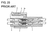
- a connector provided with a lock arm for holding a mating connector in a connected state is known e.g. from Japanese Unexamined Patent Publication No. H07-282884 .
- This connector is constructed such that a cantilever-shaped lock arm projects from the front end of the upper surface of a housing and is engageable with an engaging portion of the mating connector to be connected with the housing to hold the mating connector in a connected state.
- the housing made of a synthetic resin is integrally formed with the lock arm by molding in the above connector, a standing portion of the lock arm from the housing tends to be high, which causes a problem of enlarging the connector in height direction.
- a further example of a connector provided with a lock arm for holding a mating connector in a connected state is e.g. known from Japanese Unexamined Patent Publication No. H05-182712 .
- this connector is constructed such that a female housing 3 is fittable into a receptacle 2 of a male housing 1, a cantilever-shaped lock arm 4 is integrally formed on the upper surface of the female housing 3 and engageable with an engaging portion 5 provided on an upper part 2a of the receptacle 2 to hold the two housings 1, 3 in their connected state.
- the above connector tends to be large along height direction since the lock arm 4 and the upper part 2a of the receptacle 2 are placed one over the other in the connected state.
- US 6 146 182 discloses an electrical connector with latching means in which a pair of spring latching means is disposed in a corresponding slot of a housing from a top wall.
- US-A-4 898 549 discloses a connector built from one or more single rowed housings with long lasting locking mechanism for receiving male terminals and ends of sheathed wires connected thereto.
- This connector is further formed with means for, if and when two of the housings are laid together with their sinlge rows of holes substantially parallel, locating them with respect to mutual sliding movement.
- EP-A-1 180 822 discloses a cable connector comprising a housing containing one or more contact elements, one or more openings for accommodating a corresponding number of cables and a means for establishing a connection to a counterpart, such as a header soldered to a printed circuit board.
- EP-A-0 288 249 describes a spring latch for latching together electrical connectors for engaging plug connector modules side-by-side.
- the integral spring latch members are secured along commoned end surfaces of the modules to comprise a plug connector assembly manipulable as a unit.
- DE-A-32 09 076 describes a cover for a connector formed from two box-formed shells having sub miniature pole formations of a military standardized contact disposition.
- the present invention was developed in view of the above problem and an object thereof is to provide a connector suitable for the miniaturization.
- the lock arm made of the metallic piece is pressingly held onto or at the housing so as to be mounted on an outer surface of the housing, a projecting height I of the lock arm from the housing can be reduced as compared to connectors in which a housing is integrally formed with a lock arm by molding as in the prior art. As a result, the connector can be miniaturized.
- the locking portion projects out from the outer surface of the housing.
- the insufficient insertion of the terminal fitting can be detected by visually confirming this locking portion from the outside. If the lock arm is mounted on the housing after the terminal fittings are inserted into the housing, the lock arm can be prevented from standing as a hindrance to the visual confirmation of the locking portions.
- the lock arm is so arranged as to substantially face the locking portions and can be retracted into deformation spaces for the locking portions during the resilient deformation.
- the connector can be further miniaturized as compared to connectors in which deformation spaces for locking portions and a lock arm are separately defined.
- the lock arm includes at least one press-in or insertion portion projecting down or towards the housing and at least one press-in or inserting groove into which the press-in portion at least partly can be pressed or inserted is so formed in the housing as to have an open upper end.
- the lock arm can be held onto the housing by pressing the press-in portion into the press-in groove from above, it can be easily mounted.
- the housing includes a receptacle into which the mating connector is at least partly fittable and wherein e lock arm is engageable with an engaging portion of the mating connector to hold the mating connector in a connected state.
- the lock arm is at least partly, preferably substantially fully arranged in the lock-arm arranging space formed by cutting or recessing the receptacle.
- a connector comprising a housing including a receptacle into which a mating connector is fittable and a lock arm engageable with an engaging portion of the mating connector to hold the mating connector in a connected state, wherein the lock arm is made of a metallic piece and arranged in a lock-arm arranging space formed by cutting the receptacle.
- the connector can be made smaller as compared to connectors in which a receptacle and a lock arm are placed one over the other along height direction as in the prior art.
- the lock arm is formed such that it can undergo a substantially seesaw-like displacement and/or deformation.
- the lock arm has a lock portion engageable with an engaging portion of the mating connector, the lock portion being provided at one end of the lock portion while having an operable portion for canceling a locked state provided at the other end thereof.
- the lock arm is formed such that it can undergo a seesaw-like displacement or rocking movement and/or deformation, and has a lock portion engageable with the engaging portion provided at one end thereof while having an operable portion for canceling a locked state provided at the other end thereof.
- the lock arm can be inclined or moved or displaced by operating the operable portion, thereby disengaging the lock portion from the engaging portion.
- a reinforcing portion made of a metal plate is provided to at least partly, preferably substantially fully cover an outer surface of a part of the housing, preferably of the receptacle, where the lock-arm arranging space is formed, and the lock arm preferably is formed to be integral or unitary to the reinforcing portion.
- a reinforcing portion made of a metal plate is provided to cover an outer surface of a part of the receptacle where the lock-arm arranging space is formed by cutting, and the lock arm is formed to be integral to the reinforcing portion.
- a reduction in the strength of the housing resulting from the formation of the lock-arm arranging space in the receptacle by cutting can be compensated for by the reinforcing portion made of the metal plate. Further, since the reinforcing portion is integrally formed with the lock arm, the construction can be simplified.
- the housing is or is to be fixed to an electric or electronic device, such as a circuit board
- the reinforcing portion is integrally or unitarily formed with a board fixing portion to be fixed to the electric or electronic device, preferably the circuit board.
- the reinforcing portion is integrally formed with the board fixing portion, the construction can be further simplified.
- FIGS. 1 to 11 A first preferred embodiment of the present invention is described with reference to FIGS. 1 to 11.
- a female connector F connectable along a connecting direction CD with a mating male connector M and provided with a lock arm 40 (as a preferred movable member).
- sides of the two connectors F, M to be connected with each other are referred to as front side, and reference is made to all the figures except FIG. 4 concerning vertical direction.
- the male connector M preferably is a circuit board connector to be mounted on a circuit board K (as a preferred electric or electronic device) and includes a male housing 10 made e.g. of a synthetic resin and one or more, preferably a plurality of (forty) male terminal fittings 11 at least partly mounted or mountable in the male housing 10 at one or more stages.
- a male housing 10 made e.g. of a synthetic resin and one or more, preferably a plurality of (forty) male terminal fittings 11 at least partly mounted or mountable in the male housing 10 at one or more stages.
- the male housing 10 is narrow and long along widthwise direction WD as a whole, and includes a terminal holding portion 12 formed with one or more terminal insertion holes 12a through which the male terminal fittings 11 are insertable from behind and a receptacle 13 preferably substantially in the form of a rectangular tube projecting forward from the peripheral edge of the terminal holding portion 12.
- Twenty terminal insertion holes 12a are arranged side by side substantially at even intervals along widthwise direction WD preferably at each of upper and lower stages, wherein the terminal insertion holes 12a at the upper stage are arranged at positions displaced (offset) from those at the lower stage along widthwise direction WD.
- Each male terminal fitting 11 has its part projecting backward from the terminal holding portion 12 bent e.g.
- a front portion of the male terminal fitting 11 at least partly projecting into the receptacle 13 serves as a connector-side connecting portion 11 a electrically connectable with a female terminal fitting 21 of the female connector F, whereas the rear end thereof serves as a board-side connecting portion 11 b electrically connectable with the electric/electronic device, e.g. with a conductor path (not shown) printed on the circuit board K by soldering, welding, press fitting, or the like.
- a female housing 20 of the female connector F is at least partly fittable into the receptacle 13 substantially along the connecting direction CD from front.
- An intermediate portion (preferably substantially widthwise middle portion) of the lateral (upper) wall of the receptacle 13 extending substantially in widthwise direction WD is formed to be thinner than the opposite side portions, whereby an escaping groove 14 for letting the lock arm 40 and the like escape is formed to have an open front end.
- a fitting recess 15 into which a lock portion 43 of the lock arm 40 is at least partly fittable is formed in a portion of the lateral (upper) wall of the receptacle 13 facing the escaping groove 14, and an engaging portion 16 engageable with the lock portion 43 is formed before or near the fitting recess 15.
- the fitting recess 15 preferably is in the form of a hole made at an intermediate position of the lateral (upper) wall and substantially vertically penetrating the lateral (upper) wall to communicate with the outside.
- the engaging portion 16 is provided at the front end of the upper wall, wherein the inner surface thereof is formed into a slanted or bent surface sloped up or outward toward the front and the rear surface thereof as a locking surface engageable with the lock portion 43 is formed into a substantially straight surface substantially extending in widthwise direction WD.
- one or more, preferably four receiving recesses 17 for at least partly receiving corresponding elongated projections 26 of the female connector F are formed in each of the lateral (upper and lower) surfaces of the inner circumference of the receptacle 13. It should be noted that the male housing 10 can be fixed to the circuit board K using an unillustrated mounting member.
- the female connector F includes the female housing 20 made e.g. of a synthetic resin and one or more, preferably a plurality of (forty) female terminal fittings 21 at least partly accommodated in the female housing 20.
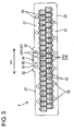
- the female housing 20 preferably is in the form of a laterally long block narrow and long along widthwise direction WD as a whole.
- the female housing 20 is formed with one or more cavities 22 into which the female terminal fittings 21 are at least partly insertable in an inserting direction ID, preferably substantially from behind, at positions substantially corresponding to the respective terminal insertion holes 12a of the male connector M.
- each female terminal fitting 21 is constructed such that a (preferably substantially box-shaped) main portion 21 a substantially hollow along forward and backward directions and a wire connecting portion, preferably comprising a barrel portion 21 b to be connected, preferably crimped or bent or folded into connection, with an end of a wire W are coupled one after the other.
- a resilient contact piece 21c which can be brought into contact with the connector-side connecting portion 11 a of the male terminal fitting 11 is provided in or at the main portion 21a.
- One or more (preferably substantially cantilever-shaped) locking portions 24 are formed in walls of the respective cavities 22 preferably substantially opposite from those walls partitioning the adjacent (upper and lower) cavities 22, specifically, in the upper walls of the cavities 22 at the upper stage and the bottom walls of the cavities 22 at the lower stage by making one or more slits 23 preferably having a substantially U-shaped plan view as shown in FIGS. 4 and 8. Since the respective slits 23 are so formed in upper and bottom surfaces 20a, 20b of the female housing 20 as to substantially communicate with the outside, the insides of the cavities 22 can be at least partly seen through the slits 23 from the outside and the respective locking portions 24 are at least partly exposed to the outside.
- Each locking portion 24 is resiliently deformable in a direction intersecting with the insertion direction ID or substantially along vertical direction and is engageable with a jaw portion 21 d of the main portion 21 a of the female terminal fitting 21 to retain the female terminal fitting 21 in the cavity 22.
- the locking portion 24 extends substantially obliquely from the rear end as a base end toward the front end as a free end in such a manner as to at least partly project into the cavity 22, and the outer surface thereof preferably is substantially continuous with the lateral (upper) surface 20a or the lateral (bottom) surface 20b (outer surface extending substantially along a side-by-side arranging direction of the cavities 22) of the female housing 20.
- a detecting portion 25 projects outward from the outer surface of the front end of each locking portion 24.
- the outer surface of the detecting portion 25 is substantially in flush with the outer surface 20a or the bottom surface 20b of the female housing 20 when the locking portion 24 is in a natural state where no force act thereon.
- the detecting portion 25 projects out from the upper surface 20a or the bottom surface 20b of the female housing 20 (see FIG. 6). Accordingly, if an attempt is made to connect the two housings 10, 20 with the locking portions 24 resiliently deformed, the front end surfaces of the detecting portions 25 come into contact with the front end surface of the receptacle 13, thereby hindering the connecting operation.
- deformation spaces 33 for the respective locking portions 24 are defined outside the upper and bottom surfaces 20a, 20b of the female housing 20 and shared as a connection space with the mating male connector M.
- the elongated projections 26 which function to guide the connecting operation of the two housings 10, 20 are provided on the lateral (upper) surface 20a and/or the lateral (bottom) surface 20b of the female housing 20. More specifically, two elongated projections 26 are provided at the substantially opposite widthwise end positions and two elongated projections 26 are provided at intermediate positions toward the widthwise center of each of the lateral (upper and bottom) surfaces 20a, 20b of the female housing 20. A total of eight elongated projections 26 are provided. Although the respective elongated projections 26 extend forward from the rear end position of the female housing 20, those 26 provided at the intermediate positions toward the widthwise center have their intermediate portions removed to be divided into front and rear sections (see FIG.
- the upper and lower elongated projections 26 arranged at intermediate positions toward the center are displaced from or with respect to each other along widthwise direction WD.
- the front end positions of the lower elongated projections 26 are substantially aligned with the front end position of the female housing 20, whereas those of the upper elongated projections 26 are retracted from the front end position of the female housing 20 and the front end surfaces thereof are overhanging or undercut surfaces sloped up or outward toward the front.
- One or more, preferably a pair of ribs 27 extending substantially along widthwise direction WD (side-by-side arranging direction of the cavities 22) are provided at the rear ends of the lateral (upper and bottom) surfaces 20a, 20b of the female housing 20 as shown in FIGS. 2 to 4. Since the ribs 27 preferably are formed substantially over the entire width area of the female housing 20 and couple the elongated projections 26 at the opposite ends, they contribute to increasing the strength of the female housing 20.
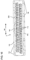
- the upper rib 27 has its intermediate portion (preferably substantially widthwise middle part) cut off or recessed over a specified (predetermined or predeterminable) range in order to let the lock arm 40 escape, thereby being divided into lateral (left and right) sections shown in FIG. 2.
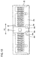
- the ribs 27 preferably have the substantially same height as the elongated projections 26 and allow an operator to place his fingers thereon upon connecting and separating the female housing 20 (see FIG. 13). Further, one or more marks 28 for letting the operator (preferably visually) confirm the positions of the respective cavities 22 are formed preferably by recessing in the rear end surfaces of the respective elongated projections 26 and the ribs 27 (see FIG. 3). It should be noted that the intervals and shape of the marks 28 can be arbitrarily changed from those shown.
- the lock arm 40 is made of a metallic piece obtained preferably by press-working a metal plate (e.g. made of a stainless steel) separate from the female housing 20, and is pressed or mounted onto the lateral (upper) surface 20a (outer surface from which the locking portions 24 can project) of the female housing 20 to be held there. More specifically, the lock arm 40 includes an arm portion 41 extending substantially along forward and backward directions FBD, and a press-in or engagement portion 42 projecting down or towards the female housing 20 from the front end or end portion of the arm portion 41 and at least partly pressable into or engageable with the female housing 20.
- a metal plate e.g. made of a stainless steel
- a front end portion of the arm portion 41 is substantially horizontal (or extending substantially along forward and backward directions FBD), and a rear portion thereof is sloped up or outward (or away from the female housing 20) toward the back.
- An intermediate portion (preferably substantially longitudinal middle) of the sloped portion of the arm portion 41 is embossed to project upward or outward (or away from the female housing 20), thereby forming the lock portion 43.
- the front surface of the lock portion 43 is a slanted surface sloped up or outward (or away from the female housing 20) toward the back (preferably slightly steeper than the sloped portion of the arm portion 41), whereas the rear surface thereof as a locking surface engageable with the engaging portion 16 is arranged at an angle different from 0° or 180°, preferably substantially in the range of about 75° to about 105° with respect to the connecting direction CD, preferably an overhanging or undercut surface sloped down or inwardly or towards the female housing 20 toward the front.
- the press-in portion 42 preferably is formed to be wider than the arm portion 41.
- one or more, preferably a pair of lock-arm holding portions 29 for holding the lock arm 40 are provided at the front end of an intermediate part (preferably substantially a widthwise middle part) of the lateral (upper) surface 20a of the female housing 20.
- the lock-arm holding portions 29 preferably are transversely spaced apart by a distance which is about the width of the arm portion 41 as shown in FIG. 4 and project upward or outward from the lateral (upper) surface 20a of the female housing 20, wherein a projecting height thereof is substantially equal to those of the elongated projections 26 and the ribs 27.
- the lock-arm holding portions 29 are formed with press-in grooves or recesses or holes 30 into which the press-in portion 41 can be at least partly pressed and which have an open end.
- the press-in grooves 30 are so formed as to recess the upper surface 20a of the female housing 20 by a specified (predetermined or predeterminable) depth.
- One or more, preferably a pair of retaining portions 31 engageable with the upper or outer surface of the arm portion 41 to retain the lock arm 40 are provided preferably immediately behind the lock-arm holding portions 29.
- the lock-arm holding portions 29 and the retaining portions 31 at least partly enter the escaping groove 14 of the receptacle 13 together with the arm portion 41 of the lock arm 40 to escape upon connecting the female housing 20 with the male housing 10.
- the lock arm 40 is resiliently deformable in a direction intersecting with the connecting direction CD or substantially along vertical direction with rear end positions (front end position of the sloped portion of the arm portion 41) of engaging parts of the arm portion 41 with the retaining portions 31 as a supporting point as shown in FIG. 8, and the arm portion 41 is retracted into a deformation space 45 defined between the arm portion 41 and the lateral (upper) surface 20a of the female housing 20 during the resilient deformation of the lock arm 40 (see FIG. 9).
- the arm portion 41 of the lock arm 40 is located at a position substantially overlapping one or more, e.g.
- the lock arm 40 can be retracted into the deformation spaces 330 for these three locking portions 240 during the resilient deformation of the lock arm 40, i.e. the deformation spaces 330 for the locking portions 240 are shared as the deformation space 45 for the lock arm 40.
- the detecting portions 250 reach an arrangement space of the arm portion 41 beyond the deformation space 45 for the lock arm 40 (see FIG. 6), i.e. the deformation spaces 330 for the locking portions 240 are or correspond to a sum of a part of the arrangement space for the lock arm 40 and the deformation space 45 for the lock arm 40.
- the lock arm 40 preferably is supported at one end with the press-in portion 42 at the front end fixed to the female housing 20, and a rear end thereof as a free end or rear end portion serves as an operable portion 44.
- the arm portion 41 can be forcibly resiliently deformed downward or toward the female housing 20, i.e. in unlocking direction.
- one or more, preferably a pair of protecting portions 32 projecting up or outward preferably to the substantially same height as the upper end position of the operable portion 44 are provided at the inner end positions of the upper rib 27 of the female housing 20.
- the two protecting portions 32 By arranging the two protecting portions 32 preferably at the substantially opposite sides of the operable portion 44, an unillustrated external wire and the like can be prevented from at least partly entering below the operable portion 44 from behind, with the result that the lock arm 40 can be prevented from being turned forward. It should be noted that the protecting portions 32 may be higher than the operable portion 44.
- the female connector F is assembled.
- the one or more female terminal fittings 21 connected, preferably crimped into connection, with the ends of the wires W are at least partly inserted into the respective cavities 22.
- the locking portions 24 are temporarily resiliently deformed in a direction intersecting the inserting direction ID by being pressed by the main portions 21 a and the detecting portions 25 at least partly project out from the lateral (upper and/or lower) surfaces 20a, 20b of the female housing 20.
- the locking portions 24 are resiliently at least partly restored to engage the jaw portions 21 d of the main portions 21 a as shown in FIG. 7, whereby the female terminal fittings 21 are retained. If the female terminal fitting 21 is left at an intermediate position during the insertion, the insufficient insertion of the female terminal fitting 21 can be detected preferably by visually conforming the projecting detecting portion 25 (250) or the female terminal fittings 21 in the cavity 22 through the slit 23.
- the lock arm 40 is mounted on the female housing 20.
- the front end of the lock arm 40 is pressed from a state shown in FIG. 7, thereby at least partly pressing the press-in portion 42 into the press-in groove(s) 30.
- the press-in portion 42 is pressed up to a proper depth in the press-in groove(s) 30 and the retaining portions 31 are engaged with the outer (upper) surface of the arm portion 41 as shown in FIG. 8, whereby the lock arm 40 is held in its press-in state.
- the lock arm 40 comes into interference with the detecting portion(s) 250 of the locking portion(s) 240 because the locking portion(s) 240 substantially facing the lock arm 40 project into the arrangement space for the lock arm 40, thereby hindering the mounting operation (see FIG. 6). In this way, the insufficient insertion of the female terminal fittings 21 can also be detected.
- the female terminal fittings 21 may be at least partly inserted after the lock arm 40 is mounted. In such a case, after the lock arm 40 is mounted, the arm portion 41 may be temporarily turned forward and then the female terminal fittings 21 may be at least partly inserted.
- the locking portions 240 and the like can be easily visually confirmed from the outside even for the e.g. three middle cavities 22 overlapping the lock arm 40.
- the lock arm 40 may be returned towards or substantially to its initial posture.
- the female connector F is connected with the male connector M along the connecting direction CD.
- the front end surfaces of the respective elongated projections 26 come substantially into contact with the front end surface of the receptacle 13, thereby hindering the connecting operation to prevent an error connection.
- the front end surfaces of the detecting portions 25 of the locking portions 24 projecting from the upper and bottom surfaces 20a, 20b of the female housing 20 come substantially into contact with the front end surface of the receptacle 13, thereby hindering the connecting operation.
- the insufficient insertion of the female terminal fittings 21 can also be securely detected (see FIG. 6).
- the elongated projections 26 at least partly enter the corresponding receiving recesses 17 to smoothly guide the connecting operation. Further, the arm portion 41 of the lock arm 40, the one or more lock-arm holding portions 29 and the one or more retaining portions 31 are let to escape into the escaping groove 14 of the receptacle 13.
- the female housing 20 is connected up to a specified (predetermined or predeterminable) depth, the slanted front surface of the lock portion 43 and the slanted front surface of the engaging portion 16 come substantially into sliding contact with each other, whereby the lock arm 40 is resiliently deformed as shown in FIG. 9.
- the lock arm 40 is resiliently deformed with the rear end positions of the engaging parts of the arm portion 41 with the retaining portions as a supporting point, and at least partly retracted into the deformation space 45 (deformation spaces 330) below or at the female housing 20 side.
- the arm portion 41 preferably is substantially horizontal or substantially parallel to the forward and backward directions FBD (being sustantially parallel to the connecting direction CD) preferably over the substantially entire length and the lower or inner surface thereof reaches the substantially same position as the lateral (upper) surface 20a of the female housing 20.
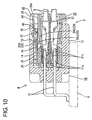
- the lock portion 43 reaches the fitting recess 15 and the lock arm 40 is resiliently at least partly restored to engage the rear surface of the lock portion 43 with the rear surface of the engaging portion 16 as shown in FIG. 10.
- the two connectors F, M are inseparably connected with each other.
- the resilient contact pieces 21 c of the female terminal fittings 21 are properly held in resilient contact with the connector-side connecting portions 11 a of the male terminal fittings 11.
- the operable portion 44 is operated, preferably pressed from above e.g. by fingers to forcibly resiliently deform the lock arm 40 towards the female housing 20. Then, as shown in FIG. 11, the lock arm 40 is resiliently deformed and the arm portion 41 and the lock portion 43 are displaced away from the engaging portion 16 and the fitting recess 15. Thus, an engaging area of the lock portion 43 with the engaging portion 16 gradually decreases.
- the female connector F can be separated from the male connector M.
- the female connector F can be easily pulled out by placing the fingers on the e.g. two ribs 27 provided on the lateral (upper and/or bottom) surfaces 20a, 20b of the female housing 20 to grip the ribs 27.
- the lock arm 40 made of a metallic piece is pressingly held onto the female housing 20.
- the projecting height of the lock arm 40 from the female housing 20 can be reduced, with the result that the female connector F can be made smaller along height direction.
- the lock arm 40 since the lock arm 40 is separate from the female housing 20, it can be exchanged if it should be broken.
- the lock arm 40 preferably is mounted or mountable on or to the female housing 20 after the female terminal fittings 21 are at least partly inserted into the female housing 20, the lock arm 40 can be preferably prevented from standing as a hindrance to the visual confirmation of the locking portions 240 (detecting portions 250) to face the lock arm 40.
- the lock arm 40 is arranged to substantially face the locking portions 240 and can be retracted into the deformation spaces 330 for the locking portions 240, i.e. the deformation spaces 330 for the locking portions 240 are shared as the deformation space 45 for the lock arm 40 during the resilient deformation of the lock arm 40.
- the female connector F can be further miniaturized as compared to connectors in which deformation spaces for locking portions and a deformation space for a lock arm are separately defined.
- the lock arm 40 is provided with the press-in portion 42 projecting down, the female housing 20 is provided with the press-in grooves 30 having the open upper ends, and the press-in portion 42 can be pressed into the press-in grooves 30 from above, the lock arm 40 can be easily mounted.
- a female housing 20 made e.g. of a synthetic resin is formed with one or more cavities 22 for at least partly accommodating one or more respective female terminal fittings 21, and one or more locking portions 24 engageable with the female terminal fittings 21 to retain them are provided in the cavities 22.
- Each locking portion 24 projects out from a lateral (upper) surface 20a or lateral (bottom) surface 20b of the female housing 20 during the resilient deformation.
- a lock arm 40 for holding a mating male connector M in a connected state is mounted on or to or at least partly in the female housing 20.
- the lock arm 40 is made of a metallic piece and includes a press-in portion 42 which can be at least partly pressed or inserted or engaged into press-in grooves 30 of the female housing 20.
- the lock arm 40 is so arranged as to substantially face the locking portions 240 and can be at least partly retracted into deformation spaces 330 for the locking portions 240 during the resilient deformation.
- FIGS. 12 to 15 A second preferred embodiment of the present invention is described with reference to FIGS. 12 to 15.
- This second embodiment mainly shows a modified mounting construction for the lock arm 40.
- no repetitive description is given on the similar or same construction as the first embodiment described above by identifying it by the same reference numerals.
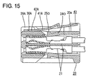
- a pair of lock-arm holding portions 29A project from a lateral (upper) surface 20a of a female housing 20 while being spaced apart by a specified (predetermined or predeterminable) distance (substantially narrower than an arm portion 41A), wherein press-in grooves 30A having open rear ends are formed in the rear surfaces of the lock-arm holding portions 29A.
- a substantially horizontal portion portion extending substantially in parallel with the connecting direction CD and/or the forward and backward directions FBD
- the lock arm 40 is pushed forward from a state shown in FIG.
- the lock arm 40 is resiliently deformable upward and downward r towards and away from the female housing 20 with a position of the arm portion 41A supported at the rear ends of the lock-arm holding portions 29A as a supporting point.
- the retaining portions 31 shown in the first embodiment preferably are not provided in the second embodiment, they may be additionally provided.
- FIGS. 16 to 24 A third preferred embodiment of the present invention is described with reference to FIGS. 16 to 24.
- a metallic member 140 integrally formed with a lock arm 143 is mounted on or to a male connector M connectable along a connecting direction CD with a mating female connector F.
- sides of the two connectors F, M to be connected with each other are referred to as front side, and reference is made to all the figures 16 to 24 except FIGS. 17 and 19 concerning vertical direction.
- the female connector F includes a female housing 110 made e.g. of a synthetic resin and one or more, preferably a plurality of (forty) female terminal fittings 111 at least partly accommodated in the female housing 110.
- the female housing 110 preferably substantially is in the form of a laterally long block narrow and long along widthwise direction WD as a whole.
- each female terminal fitting 111 is constructed such that a (preferably substantially box-shaped) main portion 111a hollow along forward and backward directions FBD and a wire connecting portion, preferably comprising a barrel portion 111 b, to be connected, preferably crimped or bent or folded into connection, with an end of a wire W are coupled one after the other.
- a resilient contact piece 111 c which can be brought into contact with a connector-side connecting portion 121 a of a male terminal fitting 121 is provided in the main portion 111a.
- One or more (preferably substantially cantilever-shaped) locking portions 113 are formed in walls of the respective cavities 112 preferably substantially opposite from those partitioning the adjacent (upper and lower) cavities 112, specifically, in the upper walls of the cavities 112 at the upper stage and the bottom walls of the cavities 112 at the lower stage by making slits of a specified (predetermined or predeterminable) shape.
- Each locking portion 113 is resiliently deformable along vertical direction and is engageable with a jaw portion 111 d of the main portion 111 a of the female terminal fitting 111 to retain the female terminal fitting 111 in the cavity 112.
- the locking portion 113 extends obliquely from the rear end or end portion as a base end substantially toward the front end as a free end in such a manner as to at least partly project into the cavity 112, and the outer surface thereof is substantially continuous with the lateral (upper or bottom) surface of the female housing 110, i.e. an outer surface of the female housing 110. Since the locking portions 113 at least partly project out from the upper and bottom surfaces of the female housing 110 while being resiliently deformed, if an attempt is made to connect the two housings 110, 120 in this state, the projecting-out locking portions 113 interfere with the front end surface of the receptacle 123 to hinder the connecting operation.
- one or more elongated projections 114 which function to guide the connecting operation of the two housings 110, 120 along the connecting direction CD are provided on the lateral (upper and bottom) surface of the female housing 110. More specifically, two elongated projections 114 are provided at the substantially opposite widthwise end positions and two elongated projections 114 are provided at intermediate positions toward the widthwise center of each of the lateral (upper and bottom) surfaces of the female housing 110. A total of eight elongated projections 114 are provided. Although the respective elongated projections 114 extend forward from the rear end position of the female housing 110, those 114 provided at the intermediate positions toward the widthwise center have their intermediate portions removed or recessed to be divided into front and rear sections (see FIG.
- the upper and lower elongated projections 114 arranged at intermediate positions toward the center are displaced from each other along widthwise direction WD.
- the front end positions of the lower elongated projections 114 are substantially aligned with the front end position of the female housing 110, whereas those of the upper elongated projections 114 are retracted from the front end position of the female housing 110 and the front end surfaces thereof are overhanging or undercut surfaces sloped up or outward toward the front.
- One or more, preferably a pair of ribs 115 extending substantially along widthwise direction WD (side-by-side arranging direction of the cavities 112) are provided at the rear ends of the lateral (upper and bottom) surfaces of the female housing 110. Since the ribs 115 preferably are formed substantially over the entire width area of the female housing 110 and substantially couple the elongated projections 114 at the opposite ends 114, they contribute to increasing the strength of the female housing 110. The ribs 115 preferably have the substantially same height as the elongated projections 114 and allow an operator to place his fingers thereon upon connecting and separating the female housing 110 (see FIG. 24).
- An engaging portion 116 engageable with the lock arm 143 of the male connector M is provided substantially in the widthwise middle of the upper surface of the female housing 110.
- the engaging portion 116 projects outward or upward from the lateral (upper) surface of the female housing 110 and is located at a position slightly retracted from the front end position of the female housing 110 (position immediately before the locking portions 113), and the width thereof is set to be substantially equal to that of a lock portion 148 of the lock arm 143.
- the front surface of the engaging portion 116 is formed into a slanted surface sloped up or outward toward the back in order to guide a movement of the lock arm 143 onto the engaging portion 16 during the connecting operation.
- the rear surface of the engaging portion 116 as a locking surface engageable with the lock arm 143 is a substantially straight surface along a direction intersecting the connecting direction CD or substantially vertical direction.
- the male connector M preferably is a circuit board connector to be mounted on a circuit board K (as a preferred electric/electronic device) and includes a male housing 120 made e.g. of a synthetic resin, one or more, preferably a plurality of (forty) male terminal fittings 121 at least partly mounted in the male housing 120, and the metallic member 140 to be described later mounted on or to or at least partly into the male housing 120.
- a circuit board connector to be mounted on a circuit board K (as a preferred electric/electronic device) and includes a male housing 120 made e.g. of a synthetic resin, one or more, preferably a plurality of (forty) male terminal fittings 121 at least partly mounted in the male housing 120, and the metallic member 140 to be described later mounted on or to or at least partly into the male housing 120.
- the male housing 120 is narrow and long along widthwise direction WD as a whole, and includes a terminal holding portion 122 formed with terminal insertion holes 122a through which the male terminal fittings 121 are at least partly insertable in an insertion direction from behind and the receptacle 123 preferably substantially in the form of a rectangular tube projecting forward from the peripheral edge of the terminal holding portion 122.
- Twenty terminal insertion holes 122a are arranged substantially side by side substantially at even intervals along widthwise direction WD at one or more stages, preferably at each of upper and lower stages, wherein the terminal insertion holes 122a at the upper stage are arranged at positions displaced from those at the lower stage along widthwise direction WD.
- Each male terminal fitting 121 has its part projecting backward from the terminal holding portion 122 bent at an angle different from 0° or 180° or down preferably substantially at a right angle, and a rear end portion thereof is bent at an angle different from 0° or 180°, preferably again substantially at a right angle, to preferably extend substantially backward.
- a front portion of the male terminal fitting 121 projecting into the receptacle 123 serves as a connector-side connecting portion 121 a electrically connectable with the female terminal fitting 111 of the female connector F, whereas the rear end thereof serves as a board-side connecting portion 121b electrically connectable with a conductor path (not shown) printed on the circuit board K preferably by soldering, (ultrasonic) welding, press fitting or the like.
- the female housing 110 of the female connector F is at least partly fittable into the receptacle 123 substantially along the connecting direction CD or from front.
- a receiving recess 124 for permitting the entrance of the engaging portion 116 is formed at an intermediate position, preferably at a substantially widthwise middle position, of the ceiling surface of the receptacle 123.
- one or more, e.g. four receiving recesses 125 for receiving the corresponding elongated projections 114 are formed in each of the lateral (bottom and ceiling) surfaces of the receptacle 123.
- a metallic-member mounting portion 126 for mounting the metallic member 140 having the lock arm 143 is formed in or on the outer circumferential surface of the receptacle 123. The constructions of the metallic member 140 and the metallic-member mounting portion 126 are described in detail below.
- the metallic member 140 preferably is formed by bending, folding and/or embossing a metal plate stamped or cut out into a specified (predetermined or predeterminable) shape from a metal or metal-like material.
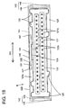
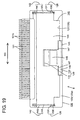
- the metallic member 140 is, as shown in FIGS. 18 to 20, comprised of a main portion 141 at least partly covering the lateral (upper) surface of the receptacle 123, a pair of fixing portions 142 projecting at an angle different from 0° or 180°, preferably substantially normal or down from the opposite lateral edges or edge portions of the main portion 141 and at least partly covering the side surfaces of the receptacle 123, and the lock arm 143 formed at the main portion 141.
- the metallic-member mounting portion 126 includes a main-portion mounting recess 127 formed in the lateral (upper) surface of the receptacle 123, a pair of fixing-portion mounting grooves 128 formed in the substantially opposite side surfaces of the receptacle 123, and a lock-arm arranging space 129 formed in an upper part 123a of the receptacle 123.
- the main portion 141 is substantially in the form of a substantially flat plate and laterally long along widthwise direction WD preferably substantially over the entire width area of the lateral (upper) surface of the receptacle 123.
- the main-portion mounting recess 127 is formed in a corresponding width area, preferably substantially over the entire width area, of the lateral (upper) part 123a of the receptacle 123 to have a depth preferably substantially corresponding or equal to the thickness of the main portion 141.
- the upper surface of the mounted main portion 141 and that of the receptacle 123 preferably are substantially in flush with each other (see FIG. 18).
- Each fixing portion 142 includes a housing fixing portion 144 preferably vertically long substantially (preferably over the substantially entire height area of the side surface of the receptacle 123), and a board fixing portion 145 projecting sideways from the lateral (bottom) end of the housing fixing portion 144, thereby preferably being substantially L-shaped as a whole (see FIG. 18). As shown in FIG.
- each fixing-portion mounting groove 128 preferably is formed substantially over the entire height area of the side portion of the receptacle 123 and includes a housing-fixing-portion accommodating portion 130 vertically or laterally penetrating the side portion of the receptacle 123 and adapted to at least partly accommodate the housing fixing portion 144, and a board-fixing-portion accommodating portion 131 which is an opening made in the side portion of the receptacle 123 for at least partly accommodating the board fixing portion 145.
- the housing fixing portion 144 has such a stepped or converging configuration as to have an upper or first portion 144a (large-width portion), a middle or intermediate or second portion 144b (middle-width portion) and a bottom or third portion 144c (small-width portion) having three different widths, whereas the board fixing portion 145 is formed to have substantially the same width as the bottom portion 144c to be coupled.
- the housing-fixing-portion accommodating portion 130 is formed such that a wider portion 130a having a width substantially equal to or larger than that of the upper or first portion 144a of the housing fixing portion 144 and a narrower portion 130b having a width substantially equal to or larger than that of the middle or second portion 144b are coupled one over or near the other, whereas the board-fixing-portion accommodating portion 131 is formed to have a width substantially equal to or larger than those of the bottom or third portion 144c of the main portion 141 and the board fixing portion 145.
- One or more, preferably a pair of retaining portions 146 project sideways from the substantially opposite lateral edges or edge portions of the middle or second portion 144b of the housing fixing portion 144.
- the board fixing portions 145 are fixed to the circuit board K by soldering, (ultrasonic) welding, press-fitting or the like.
- the projecting ends (outer ends) of the board fixing portions 145 preferably are set to be substantially in flush with the side surfaces of the receptacle 123.
- the lock arm 143 is made of a metallic piece formed by making a specified slit in the main portion 141 of the metallic member 140.
- the lock arm 143 preferably includes one or more, preferably a pair of supporting portions 147 coupled to the (preferably substantially opposite) inner edge(s) of the main portion 141, the lock portion 148 projecting backward from the supporting portions 147, and an operable portion 149 projecting forward from the supporting portions 147.
- the lock portion 148 is formed such that an inclined portion sloped down or inwardly or towards the male housing 120 toward the back and a substantially horizontal portion substantially horizontal (or parallel to the forward and backward directions FBD) at the rear end are coupled to each other.
- the rear surface of the engaging portion 116 is engageable with the rear edge of the horizontal portion.
- the front surface of the inclined portion of the lock portion 148 is a slanted surface substantially along the front surface of the engaging portion 116.
- the operable portion 149 is substantially horizontal preferably over the substantially entire length and wider than (e.g. about twice) the lock portion 148.
- the lock arm 143 can resiliently undergo a seesaw-like or displacement or rocking movement with the supporting portions 147 as a supporting point, so that the operable portion 149 and the lock portion 148 are displaced in opposite directions, the lock portion 148 being displaced in a displacement direction DD1 substantially outward or away from the male housing 120 and the operable portion 149 being displaced in a displacement direction DD2 substantially inward or towards the male housing 120 (see FIG. 22), the displacement directions DD1 and DD2 being substantially opposite to each other. Accordingly, when the operable portion 149 is pressed down or towards the male housing 120 (direction DD2), the lock portion 148 is displaced upward or away from the male housing 120 (direction DD1), i.e. unlocking direction.
- the upper part 123a of the receptacle 123 is cut to form the lock-arm arranging space 129 for at least partly accommodating the lock arm 143.
- the lock-arm arranging space 129 is comprised of a lock-portion accommodating portion 132 in the form of a substantially rectangular hole vertically penetrating the upper part 123a at an intermediate position (preferably at a substantially widthwise middle position) of the upper part 123a of the receptacle 123, and an operable-portion accommodating portion 133 formed by thinning or recessing a front end portion of the upper part 123a of the receptacle 123.
- the lock-portion accommodating portion 132 substantially communicates with the operable-portion accommodating portion 133 and the aforementioned receiving recess 124.
- the lock portion 148 is at least partly located in the lock-portion accommodating portion 132
- the operable portion 149 is at least partly located in the operable-portion accommodating portion 133
- the supporting portions 147 are held substantially in contact with or in proximity to a bottom or inner surface 133a of the operable-portion accommodating portion 133.
- This bottom surface 133a of the operable-portion accommodating portion 133 is sloped down or inwardly toward the front (more distanced from the operable portion 147 in a direction away from a position in contact with the supporting portions 147), whereby a specified (predetermined or predeterminable) clearance for permitting the inclination of the operable portion 149 in the displacement direction DD2 is defined between the bottom or inner surface 133a and the operable portion 149. Since the operable portion 149 can be brought substantially into contact with the bottom surface 133a before the lock arm 143 is deformed beyond its resiliency limit at the time of being pressed, the operable portion 149 is prevented from being excessively pressed.
- the upper or outer surface of the operable portion 149 and that of the receptacle 123 preferably are substantially in flush, and/or the bottom end surface of the rear end of the lock portion 148 is substantially in flush with the ceiling surface of the receptacle 123.
- the lock arm 143 is located substantially at the same position as the upper part 123a of the receptacle 123 with respect to height direction. Since the metallic member 140 preferably is entirely accommodated in the metallic-member mounting portion 126 in this way, it does not project out from the outer circumferential surface of the male housing 120. It should be noted that a part (portion proximate to the supporting portions 147 and the operable portion 149) of the main portion 141 is at least partly accommodated in the operable-portion accommodating portion 133.
- the main portion 141 of the metallic member 140 can at least partly, preferably substantially fully cover the upper surface (outer surface) of the upper part 123a of the receptacle 123 where the lock-arm arranging space 129 is defined, a reduction in the strength of the upper part 123a resulting from the formation of the lock-arm arranging space 129 by cutting can be compensated for reinforcement.
- the main portion 141 preferably also functions as a reinforcing portion.
- the respective male terminal fittings 121 are at least partly inserted into the corresponding terminal insertion holes 122a from the inserting direction, preferably substantially from behind, and the metallic member 140 is mounted into or onto the metallic-member mounting portion 126 substantially laterally or from above.
- the metallic member 140 is pushed to a substantially proper depth or position, one or more steps 144d at the bottom ends of the upper portions 144a of the housing fixing portions 144 come into contact with steps or projections 130c at the bottom ends of the wider portions 130b of the housing-fixing-portion accommodating portions 130 as shown in FIG.
- the lower surfaces of the board fixing portions 145 preferably are located at such positions as to be substantially in flush with the bottom surface of the male housing 120 (such positions that the upper surface of the main portion 141 is substantially in flush with that of the receptacle 123).
- the retaining portions 146 preferably bite in or engage or thrust at least partly into the edges of the narrower portions 130b to prevent an upward detaching movement (movement in a detaching direction) of the metallic member 140. It does not matter which of the inserting operation of the male terminal fittings 121 and the mounting operation of the metallic member 140 is carried out first.
- the male connector M assembled as above is or is to be fixed to the circuit board K.
- both board fixing portions 145 are placed at positions where they are planned to be fixed to the circuit board K, e.g. molten solder is attached to the peripheral edges of both board fixing portions 145 and solidified to fix the male connector M to the circuit board K.
- the board-side connecting portions 121 b of the male terminal fittings 121 are successively soldered to the corresponding conductor paths on the circuit board K.
- the female connector F separately assembled is connected with the male connector M fixed to the circuit board K.
- the female housing 120 is at least partly fitted into the receptacle 123 of the male housing 120 along the connecting direction CD from a state shown in FIG. 21, the respective elongated projections 114 enter the receiving recesses 125 to smoothly guide the connecting operation.
- the female housing 110 is connected up to a specified (predetermined or predeterminable) depth, the slanted front surface of the lock portion 148 and the slanted front surface of the engaging portion 116 come substantially into sliding contact with each other, whereby the lock arm 143 is resiliently deformed and/or displaced as shown in FIG. 22.
- the lock arm 143 undergoes a seesaw-like displacement or rocking movement substantially about the supporting portions 147, whereby the lock portion 148 moves onto the engaging portion 116 to be displaced upward or in the displacement direction DD1, and the operable portion 149 is displaced downward or in the displacement direction DD2 (see enlarged view in FIG. 22).
- the engaging portion 116 reaches a position behind the lock portion 148, and the lock arm 143 is resiliently at least partly restored to engage the rear edge of the lock portion 148 with the rear surface of the engaging portion 116 as shown in FIG. 23.
- the two connectors F, M are inseparably connected with each other.
- the resilient contact pieces 111 c of the female terminal fittings 111 are substantially properly held in resilient contact with the connector-side connecting portions 121 a of the male terminal fittings 121.
- the operable portion 149 is operated (e.g. pressed from above by fingers) to forcibly resiliently deform and/or displace the lock arm 143.
- the lock arm 143 undergoes a seesaw-like displacement or rocking movement substantially about the supporting portions 147 to displace the lock portion 148 upward or in the displacement direction DD1 (direction away from the engaging portion 116) and to gradually reduce an area of engagement with the engaging portion 116.
- the supporting portions 147 are or may be supported from below by being held substantially in contact with the bottom surface 133a of the operable-portion accommodating portion 133.
- the female connector F can be separated from the male connector M.
- the female connector F can be easily pulled out by placing the fingers on the one or more ribs 115 of the female housing 110 to grip the ribs 115. If an attempt is made to excessively press the operable portion 149, the operable portion 149 comes substantially into contact with the bottom surface 133a of the operable-portion accommodating portion 133 to prevent any further displacement thereof. Therefore, such a situation where the lock arm 143 is substantially plastically deformed preferably can be avoided.
- the receptacle 123 of the male housing 120 is cut to form the lock-arm arranging space 129 and the lock arm 143 made of a metallic piece is at least partly, preferably substantially fully arranged therein.
- the male connector M can be made smaller as compared to connectors in which a receptacle and a lock arm are placed one over the other along height direction as in the prior art.
- the lock arm 143 is formed such that it can undergo a seesaw-like displacement or rocking movement and has the lock portion 148 engageable with the engaging portion 116 provided at the rear end thereof and the operable portion 149 provided at the front end thereof, the lock arm 143 can be inclined by operating the operable portion 149 to disengage the lock portion 148 from the engaging portion 116.
- the main portion 141 made of a metal plate is placed to at least partly, preferably substantially fully cover the outer surface of the upper part 123a of the receptacle 123 where the lock-arm arranging space 129 is formed preferably by cutting or recessing, a reduction in the strength of the male housing 120 resulting from the formation of the lock-arm arranging space 129 can be compensated for.
- the main portion 141 is integrally or unitarily formed with the lock arm 143, the construction can be simplified.
- the board fixing portions 145 are formed to be integral to the main portion 141 via the housing fixing portions 144, the construction can be further simplified.
- a male housing 120 is provided with a receptacle 123 into which a female connector F is at least partly fittable.
- the male housing 120 is provided with a metallic-member mounting portion 126 used to at least partly mount or accommodate a metallic member 140, and the metallic member 140 is provided with a lock arm 143 engageable with an engaging portion 116 of the female connector F.
- the metallic-member mounting portion 126 includes a lock-arm arranging space 129 in which the lock arm 143 can be at least partly accommodated, and the lock-arm arranging space 129 is formed by cutting or recessing an upper part 23a of the receptacle 123.
Claims (9)
- Connecteur (F ; M), comprenant :un boîtier (20 ; 120) réalisé en une résine synthétique, etun bras de verrouillage (40 ; 143) afin de maintenir un connecteur conjugué (M ; F) dans un état raccordé,dans lequel le bras de verrouillage (40 ; 143) est réalisé en une pièce métallique et maintenu de manière pressée sur le boîtier (20 ; 120) ou au niveau de celui-ci
dans lequel le bras de verrouillage (40 ; 143) est monté sur une surface externe (20a, 127) du boîtier (20 ; 120),
dans lequel le boîtier (20) comporte une ou plusieurs cavités (22) afin de recevoir au moins partiellement un ou plusieurs raccords de borne respectifs (21),
caractérisé en ce que
une ou plusieurs parties de verrouillage (24), pouvant être couplées aux raccords de borne respectifs (21) afin de les retenir, sont formées dans les cavités respectives (22) et peuvent au moins partiellement s'étendre à partir d'une surface externe (20a ; 20b) du boîtier (20) au cours de la déformation élastique, et
le bras de verrouillage (40) est monté sur la surface externe (20a ; 20b) du boîtier (20) à partir duquel les parties de verrouillage (24) peuvent au moins partiellement s'étendre. - Connecteur selon la revendication 1, dans lequel le bras de verrouillage (40) est agencé de manière à faire sensiblement face aux parties de verrouillage (24) et peut être rétracté dans les espaces de déformation (330) pour les parties de verrouillage (240) au cours de la déformation élastique.
- Connecteur selon une ou plusieurs des revendications précédentes dans lequel le bras de verrouillage (40) comporte au moins une partie de pression (42 ; 42A) s'étendant vers le bas ou vers le boîtier (20) et au moins une rainure de pression (30 ; 30A) dans laquelle la partie de pression (42 ; 42A) peut être au moins partiellement pressée est formée sur le boîtier (20) de manière à présenter une extrémité externe ouverte.
- Connecteur selon une ou plusieurs des revendications précédentes, dans lequel le boîtier (120) comporte un réceptacle (123) à l'intérieur duquel le connecteur conjugué (F) peut, au moins partiellement, être assemblé et dans lequel un bras de verrouillage (143) peut être couplé avec une partie de couplage (116) du connecteur conjugué (F) afin de maintenir le connecteur conjugué (F) dans un état raccordé.
- Connecteur selon la revendication 4, dans lequel le bras de verrouillage (143) est au moins partiellement, de préférence, presque entièrement, agencé dans un espace d'agencement de bras de verrouillage (129) formé par découpe ou formation en creux du réceptacle (123).
- Connecteur selon une ou plusieurs des revendications précédentes, dans lequel le bras de verrouillage (143) est formé de telle sorte qu'il peut subir un déplacement et/ou une déformation sensiblement en dent de scie.
- Connecteur selon une ou plusieurs des revendications précédentes, dans lequel le bras de verrouillage (40 ; 143) présente une partie de verrouillage (43 ; 148) pouvant être couplée à une partie de couplage (16 ; 116) du connecteur conjugué (M ; F), la partie de verrouillage (43 ; 148) étant formée au niveau d'une première extrémité du bras de verrouillage (40 ; 143), tout en présentant une partie de commande (44 ; 149), destinée à annuler un état verrouillé, agencée sur l'autre extrémité de celui-ci.
- Connecteur selon une ou plusieurs des revendications précédentes, dans lequel une partie de renforcement (141) réalisée en une plaque métallique est formée de manière à recouvrir au moins partiellement, de préférence, presque totalement, une surface externe d'une partie (123a) du boîtier (120), de préférence, du réceptacle (123), sur laquelle l'espace d'agencement de bras de verrouillage (129) est formé, et le bras de verrouillage (143) est, de préférence, formé de manière intégrale ou unitaire avec la partie de renforcement (141).
- Connecteur selon la revendication 8, dans lequel le boîtier (120) doit être fixé sur un dispositif électrique ou électronique tel qu'un circuit imprimé (K), et la partie de renforcement (141) est formée de manière intégrale ou unitaire avec une partie de fixation de plaque (145) à fixer sur le dispositif électrique ou électronique (K).
Applications Claiming Priority (4)
| Application Number | Priority Date | Filing Date | Title |
|---|---|---|---|
| JP2004000624 | 2004-01-05 | ||
| JP2004000624A JP2005197035A (ja) | 2004-01-05 | 2004-01-05 | コネクタ |
| JP2004004667A JP2005197184A (ja) | 2004-01-09 | 2004-01-09 | コネクタ |
| JP2004004667 | 2004-01-09 |
Publications (3)
| Publication Number | Publication Date |
|---|---|
| EP1557908A2 EP1557908A2 (fr) | 2005-07-27 |
| EP1557908A3 EP1557908A3 (fr) | 2005-08-31 |
| EP1557908B1 true EP1557908B1 (fr) | 2007-08-15 |
Family
ID=34635675
Family Applications (1)
| Application Number | Title | Priority Date | Filing Date |
|---|---|---|---|
| EP04030924A Expired - Fee Related EP1557908B1 (fr) | 2004-01-05 | 2004-12-28 | Un connecteur |
Country Status (5)
| Country | Link |
|---|---|
| US (1) | US7008254B2 (fr) |
| EP (1) | EP1557908B1 (fr) |
| KR (1) | KR100740849B1 (fr) |
| CN (1) | CN100377444C (fr) |
| DE (1) | DE602004008208T2 (fr) |
Families Citing this family (16)
| Publication number | Priority date | Publication date | Assignee | Title |
|---|---|---|---|---|
| JP4267641B2 (ja) * | 2006-06-02 | 2009-05-27 | タイコエレクトロニクスアンプ株式会社 | 電気コネクタ組立体 |
| US7448896B2 (en) * | 2006-06-22 | 2008-11-11 | John Mezzalingua Associates, Inc. | Connector release tab |
| DE202006020722U1 (de) * | 2006-11-17 | 2009-08-13 | Phoenix Contact Gmbh & Co. Kg | Elektrische Steckverbinderkupplung |
| JP5012072B2 (ja) * | 2007-02-14 | 2012-08-29 | 住友電装株式会社 | 基板用コネクタ |
| KR100866081B1 (ko) * | 2007-02-28 | 2008-10-30 | 한국단자공업 주식회사 | 이중 잠금 리셉터클 단자 커넥터 |
| KR100955647B1 (ko) | 2008-03-27 | 2010-05-06 | 한국단자공업 주식회사 | 수형 하우징과 암형 하우징을 포함하는 커넥터 조립체 |
| DE102009058616B4 (de) * | 2009-12-17 | 2011-11-10 | Harting Electronics Gmbh & Co. Kg | Leiterplattensteckverbinder mit Verriegelungsvorrichtung |
| US8764211B2 (en) * | 2010-05-26 | 2014-07-01 | Doug Fredrickson | Non-opaque junction box cover with troubleshooting electronic circuit board |
| US20140057501A1 (en) * | 2012-08-27 | 2014-02-27 | GM Global Technology Operations LLC | Electrical-mechanical fastening device for motor vehicles |
| JP6196961B2 (ja) * | 2014-12-11 | 2017-09-13 | 矢崎総業株式会社 | コネクタ |
| CN106953190B (zh) * | 2017-03-03 | 2019-07-26 | 中航光电科技股份有限公司 | 连接器、连接器接触件、连接器壳体组件及连接器壳体 |
| JP6885245B2 (ja) * | 2017-07-18 | 2021-06-09 | 住友電装株式会社 | コネクタ |
| JP6575586B2 (ja) * | 2017-12-21 | 2019-09-18 | 株式会社オートネットワーク技術研究所 | シールド端子 |
| JP6889842B2 (ja) * | 2018-02-26 | 2021-06-18 | 住友電装株式会社 | コネクタ |
| JP6605660B1 (ja) * | 2018-06-19 | 2019-11-13 | 日本航空電子工業株式会社 | コネクタ装置、コネクタ及び相手側コネクタ |
| JP7281089B2 (ja) * | 2019-11-29 | 2023-05-25 | 住友電装株式会社 | コネクタ |
Citations (3)
| Publication number | Priority date | Publication date | Assignee | Title |
|---|---|---|---|---|
| DE3209076A1 (de) * | 1982-03-12 | 1983-09-22 | FCT Electronic GmbH, 8000 München | Abdeckhaube fuer steckverbinder |
| US4898549A (en) * | 1986-01-28 | 1990-02-06 | Omron Tateisi Electronics Co. | Connector built from one or more single rowed housings, with long lasting locking mechanism |
| EP1180822A1 (fr) * | 2000-08-11 | 2002-02-20 | F.C.I. - Framatome Connectors International | Connecteur de câble et kit de réalisation d'un connecteur de câble |
Family Cites Families (27)
| Publication number | Priority date | Publication date | Assignee | Title |
|---|---|---|---|---|
| GB1463751A (en) * | 1974-05-03 | 1977-02-09 | Amp Inc | Electrical tab receptacle |
| US4735583A (en) * | 1987-04-24 | 1988-04-05 | Amp Incorporated | Spring latch for latching together electrical connectors and improved latching system |
| JPH0313682U (fr) * | 1989-06-26 | 1991-02-12 | ||
| JPH03120742A (ja) | 1989-10-04 | 1991-05-22 | Hitachi Ltd | 半導体装置のエージング方法、及び、同装置 |
| JPH0754724B2 (ja) * | 1989-11-17 | 1995-06-07 | 菱星電装株式会社 | コネクタのロック機構 |
| US5171161A (en) * | 1991-05-09 | 1992-12-15 | Molex Incorporated | Electrical connector assemblies |
| JPH0568085A (ja) | 1991-09-10 | 1993-03-19 | Nec Corp | 自動交換機の局データ設定方式 |
| JP2634528B2 (ja) * | 1991-12-27 | 1997-07-30 | 矢崎総業株式会社 | コネクタ |
| JPH0568085U (ja) * | 1992-02-19 | 1993-09-10 | 菱星電装株式会社 | コネクタのロック機構 |
| JP3314100B2 (ja) | 1993-03-12 | 2002-08-12 | 菱星電装株式会社 | コネクタのロック機構 |
| US5637014A (en) * | 1994-01-31 | 1997-06-10 | Mitsumi Electric Co., Ltd. | Electrical connector |
| JP3053522B2 (ja) * | 1994-04-12 | 2000-06-19 | 株式会社フジクラ | コネクタ |
| US5685739A (en) * | 1996-02-14 | 1997-11-11 | The Whitaker Corporation | Shielded electrical connector |
| JP2708040B2 (ja) | 1996-07-01 | 1998-02-04 | 株式会社エンプラス | Tcp用icキャリア |
| JPH1032043A (ja) | 1996-07-15 | 1998-02-03 | Hosiden Corp | コネクタ構造及びそのプラグとソケット |
| JPH10321292A (ja) | 1997-05-16 | 1998-12-04 | Sumitomo Wiring Syst Ltd | コネクタ |
| US6045404A (en) * | 1997-06-30 | 2000-04-04 | The Whitaker Corporation | Electrical connector having a terminal position assurance device |
| JPH11185878A (ja) * | 1997-12-25 | 1999-07-09 | Matsushita Electric Works Ltd | コネクタプラグのロック構造 |
| JP3365612B2 (ja) | 1998-01-30 | 2003-01-14 | 富士通株式会社 | 電子装置用試験装置 |
| EP0933835B1 (fr) * | 1998-02-03 | 2003-09-10 | The Whitaker Corporation | Connecteur électrique |
| JPH11326379A (ja) | 1998-03-12 | 1999-11-26 | Fujitsu Ltd | 電子部品用コンタクタ及びその製造方法及びコンタクタ製造装置 |
| JP2000214216A (ja) | 1999-01-26 | 2000-08-04 | Hitachi Ltd | 半導体検査装置 |
| JP3559725B2 (ja) | 1999-06-28 | 2004-09-02 | 株式会社ルネサステクノロジ | 半導体素子検査用ソケット、半導体装置の検査方法及び製造方法 |
| US6123575A (en) * | 1999-07-30 | 2000-09-26 | Huang; Wayne | Electrical card connector with mixed latching means |
| US6146182A (en) * | 1999-08-13 | 2000-11-14 | Hon Hai Precision Ind. Co., Ltd. | Electrical connector with latching means |
| JP2002141151A (ja) | 2000-11-06 | 2002-05-17 | Texas Instr Japan Ltd | ソケット |
| JP3546384B2 (ja) | 2001-06-04 | 2004-07-28 | 日本航空電子工業株式会社 | コネクタのロック装置 |
-
2004
- 2004-12-28 DE DE602004008208T patent/DE602004008208T2/de active Active
- 2004-12-28 EP EP04030924A patent/EP1557908B1/fr not_active Expired - Fee Related
-
2005
- 2005-01-03 US US11/028,097 patent/US7008254B2/en not_active Expired - Fee Related
- 2005-01-05 KR KR1020050000928A patent/KR100740849B1/ko not_active IP Right Cessation
- 2005-01-05 CN CNB200510003744XA patent/CN100377444C/zh not_active Expired - Fee Related
Patent Citations (3)
| Publication number | Priority date | Publication date | Assignee | Title |
|---|---|---|---|---|
| DE3209076A1 (de) * | 1982-03-12 | 1983-09-22 | FCT Electronic GmbH, 8000 München | Abdeckhaube fuer steckverbinder |
| US4898549A (en) * | 1986-01-28 | 1990-02-06 | Omron Tateisi Electronics Co. | Connector built from one or more single rowed housings, with long lasting locking mechanism |
| EP1180822A1 (fr) * | 2000-08-11 | 2002-02-20 | F.C.I. - Framatome Connectors International | Connecteur de câble et kit de réalisation d'un connecteur de câble |
Also Published As
| Publication number | Publication date |
|---|---|
| KR20050072075A (ko) | 2005-07-08 |
| US7008254B2 (en) | 2006-03-07 |
| US20050148229A1 (en) | 2005-07-07 |
| EP1557908A2 (fr) | 2005-07-27 |
| DE602004008208T2 (de) | 2008-05-15 |
| KR100740849B1 (ko) | 2007-07-20 |
| CN100377444C (zh) | 2008-03-26 |
| EP1557908A3 (fr) | 2005-08-31 |
| DE602004008208D1 (de) | 2007-09-27 |
| CN1645683A (zh) | 2005-07-27 |
Similar Documents
| Publication | Publication Date | Title |
|---|---|---|
| EP1936749B1 (fr) | Organe de contact, connecteur et procédé de fabrication | |
| JP3121388U (ja) | プラグコネクタ及びその組立 | |
| US7530861B2 (en) | Connector | |
| EP1557908B1 (fr) | Un connecteur | |
| EP1587178B1 (fr) | Connecteur | |
| EP1626464B1 (fr) | Connecteur blindé | |
| EP1986284A2 (fr) | Connecteur et son procédé d'assemblage | |
| US6659797B2 (en) | Connector with resiliently deflectable lock arm | |
| EP1030411A1 (fr) | Connecteur de raccordement | |
| EP1983618B1 (fr) | Connecteur | |
| EP1641083B1 (fr) | Connecteur et assemblage de connecteurs | |
| EP1986288B1 (fr) | Borne de court-circuit, connecteur et son procédé d'assemblage | |
| US6533615B2 (en) | Shielding terminal and a connector provided therewith | |
| EP1863135A2 (fr) | Connecteur et gabarit de déblocage de celui-ci | |
| EP1801925B1 (fr) | Connecteur et ensemble de connecteurs | |
| EP1548894B1 (fr) | Connecteur | |
| EP0905823A1 (fr) | Connecteur électrique | |
| US20040097113A1 (en) | Connector | |
| EP1303009B1 (fr) | Boîtier, connecteur de raccordement et méthode de montage | |
| EP1538706B1 (fr) | Support de retenue pour connecteur | |
| EP1134848B1 (fr) | Connecteur et ensemble de bornes de contact | |
| EP1801926B1 (fr) | Connecteur et ensemble de connecteurs | |
| JP4968793B2 (ja) | 電気コネクタ組立体 | |
| US6488547B2 (en) | Connector with longitudinally spaced locks for retaining terminal fittings | |
| EP1705757A1 (fr) | Connecteur et méthode de l'assembler |
Legal Events
| Date | Code | Title | Description |
|---|---|---|---|
| PUAI | Public reference made under article 153(3) epc to a published international application that has entered the european phase |
Free format text: ORIGINAL CODE: 0009012 |
|
| PUAL | Search report despatched |
Free format text: ORIGINAL CODE: 0009013 |
|
| 17P | Request for examination filed |
Effective date: 20050113 |
|
| AK | Designated contracting states |
Kind code of ref document: A2 Designated state(s): AT BE BG CH CY CZ DE DK EE ES FI FR GB GR HU IE IS IT LI LT LU MC NL PL PT RO SE SI SK TR |
|
| AX | Request for extension of the european patent |
Extension state: AL BA HR LV MK YU |
|
| AK | Designated contracting states |
Kind code of ref document: A3 Designated state(s): AT BE BG CH CY CZ DE DK EE ES FI FR GB GR HU IE IS IT LI LT LU MC NL PL PT RO SE SI SK TR |
|
| AX | Request for extension of the european patent |
Extension state: AL BA HR LV MK YU |
|
| AKX | Designation fees paid |
Designated state(s): DE FR GB |
|
| GRAP | Despatch of communication of intention to grant a patent |
Free format text: ORIGINAL CODE: EPIDOSNIGR1 |
|
| GRAS | Grant fee paid |
Free format text: ORIGINAL CODE: EPIDOSNIGR3 |
|
| GRAA | (expected) grant |
Free format text: ORIGINAL CODE: 0009210 |
|
| AK | Designated contracting states |
Kind code of ref document: B1 Designated state(s): DE FR GB |
|
| REG | Reference to a national code |
Ref country code: GB Ref legal event code: FG4D |
|
| REF | Corresponds to: |
Ref document number: 602004008208 Country of ref document: DE Date of ref document: 20070927 Kind code of ref document: P |
|
| ET | Fr: translation filed | ||
| PLBE | No opposition filed within time limit |
Free format text: ORIGINAL CODE: 0009261 |
|
| STAA | Information on the status of an ep patent application or granted ep patent |
Free format text: STATUS: NO OPPOSITION FILED WITHIN TIME LIMIT |
|
| 26N | No opposition filed |
Effective date: 20080516 |
|
| GBPC | Gb: european patent ceased through non-payment of renewal fee |
Effective date: 20081228 |
|
| PG25 | Lapsed in a contracting state [announced via postgrant information from national office to epo] |
Ref country code: GB Free format text: LAPSE BECAUSE OF NON-PAYMENT OF DUE FEES Effective date: 20081228 |
|
| PGFP | Annual fee paid to national office [announced via postgrant information from national office to epo] |
Ref country code: FR Payment date: 20130107 Year of fee payment: 9 |
|
| PGFP | Annual fee paid to national office [announced via postgrant information from national office to epo] |
Ref country code: DE Payment date: 20121231 Year of fee payment: 9 |
|
| REG | Reference to a national code |
Ref country code: DE Ref legal event code: R119 Ref document number: 602004008208 Country of ref document: DE |
|
| REG | Reference to a national code |
Ref country code: FR Ref legal event code: ST Effective date: 20140829 |
|
| REG | Reference to a national code |
Ref country code: DE Ref legal event code: R119 Ref document number: 602004008208 Country of ref document: DE Effective date: 20140701 |
|
| PG25 | Lapsed in a contracting state [announced via postgrant information from national office to epo] |
Ref country code: DE Free format text: LAPSE BECAUSE OF NON-PAYMENT OF DUE FEES Effective date: 20140701 |
|
| PG25 | Lapsed in a contracting state [announced via postgrant information from national office to epo] |
Ref country code: FR Free format text: LAPSE BECAUSE OF NON-PAYMENT OF DUE FEES Effective date: 20131231 |