EP1548460A1 - Radarvorrichtung - Google Patents
Radarvorrichtung Download PDFInfo
- Publication number
- EP1548460A1 EP1548460A1 EP04030287A EP04030287A EP1548460A1 EP 1548460 A1 EP1548460 A1 EP 1548460A1 EP 04030287 A EP04030287 A EP 04030287A EP 04030287 A EP04030287 A EP 04030287A EP 1548460 A1 EP1548460 A1 EP 1548460A1
- Authority
- EP
- European Patent Office
- Prior art keywords
- pulse width
- signal
- detection signal
- generates
- modulation signal
- Prior art date
- Legal status (The legal status is an assumption and is not a legal conclusion. Google has not performed a legal analysis and makes no representation as to the accuracy of the status listed.)
- Ceased
Links
- 238000001514 detection method Methods 0.000 claims abstract description 260
- 230000003111 delayed effect Effects 0.000 claims abstract description 75
- 230000000630 rising effect Effects 0.000 claims abstract description 35
- 230000005540 biological transmission Effects 0.000 claims abstract description 18
- 239000000284 extract Substances 0.000 claims abstract description 10
- 238000010276 construction Methods 0.000 description 25
- 102100040844 Dual specificity protein kinase CLK2 Human genes 0.000 description 11
- 101000749291 Homo sapiens Dual specificity protein kinase CLK2 Proteins 0.000 description 11
- 238000005070 sampling Methods 0.000 description 9
- 238000010586 diagram Methods 0.000 description 7
- 102100040856 Dual specificity protein kinase CLK3 Human genes 0.000 description 5
- 101000749304 Homo sapiens Dual specificity protein kinase CLK3 Proteins 0.000 description 5
- 230000003321 amplification Effects 0.000 description 5
- 238000003199 nucleic acid amplification method Methods 0.000 description 5
- 238000006243 chemical reaction Methods 0.000 description 4
- 238000005259 measurement Methods 0.000 description 4
- 102100040858 Dual specificity protein kinase CLK4 Human genes 0.000 description 3
- 101000749298 Homo sapiens Dual specificity protein kinase CLK4 Proteins 0.000 description 3
- 230000001934 delay Effects 0.000 description 3
- 238000007493 shaping process Methods 0.000 description 3
- 239000013078 crystal Substances 0.000 description 2
- 238000004519 manufacturing process Methods 0.000 description 1
- 230000001360 synchronised effect Effects 0.000 description 1
- 230000002123 temporal effect Effects 0.000 description 1
Images


Classifications
-
- G—PHYSICS
- G01—MEASURING; TESTING
- G01R—MEASURING ELECTRIC VARIABLES; MEASURING MAGNETIC VARIABLES
- G01R29/00—Arrangements for measuring or indicating electric quantities not covered by groups G01R19/00 - G01R27/00
- G01R29/02—Measuring characteristics of individual pulses, e.g. deviation from pulse flatness, rise time or duration
- G01R29/023—Measuring pulse width
-
- G—PHYSICS
- G01—MEASURING; TESTING
- G01S—RADIO DIRECTION-FINDING; RADIO NAVIGATION; DETERMINING DISTANCE OR VELOCITY BY USE OF RADIO WAVES; LOCATING OR PRESENCE-DETECTING BY USE OF THE REFLECTION OR RERADIATION OF RADIO WAVES; ANALOGOUS ARRANGEMENTS USING OTHER WAVES
- G01S13/00—Systems using the reflection or reradiation of radio waves, e.g. radar systems; Analogous systems using reflection or reradiation of waves whose nature or wavelength is irrelevant or unspecified
- G01S13/02—Systems using reflection of radio waves, e.g. primary radar systems; Analogous systems
- G01S13/06—Systems determining position data of a target
- G01S13/08—Systems for measuring distance only
- G01S13/10—Systems for measuring distance only using transmission of interrupted, pulse modulated waves
- G01S13/14—Systems for measuring distance only using transmission of interrupted, pulse modulated waves wherein a voltage or current pulse is initiated and terminated in accordance respectively with the pulse transmission and echo reception
- G01S13/16—Systems for measuring distance only using transmission of interrupted, pulse modulated waves wherein a voltage or current pulse is initiated and terminated in accordance respectively with the pulse transmission and echo reception using counters
-
- G—PHYSICS
- G01—MEASURING; TESTING
- G01S—RADIO DIRECTION-FINDING; RADIO NAVIGATION; DETERMINING DISTANCE OR VELOCITY BY USE OF RADIO WAVES; LOCATING OR PRESENCE-DETECTING BY USE OF THE REFLECTION OR RERADIATION OF RADIO WAVES; ANALOGOUS ARRANGEMENTS USING OTHER WAVES
- G01S13/00—Systems using the reflection or reradiation of radio waves, e.g. radar systems; Analogous systems using reflection or reradiation of waves whose nature or wavelength is irrelevant or unspecified
- G01S13/02—Systems using reflection of radio waves, e.g. primary radar systems; Analogous systems
- G01S13/06—Systems determining position data of a target
- G01S13/08—Systems for measuring distance only
- G01S13/10—Systems for measuring distance only using transmission of interrupted, pulse modulated waves
- G01S13/103—Systems for measuring distance only using transmission of interrupted, pulse modulated waves particularities of the measurement of the distance
-
- G—PHYSICS
- G01—MEASURING; TESTING
- G01S—RADIO DIRECTION-FINDING; RADIO NAVIGATION; DETERMINING DISTANCE OR VELOCITY BY USE OF RADIO WAVES; LOCATING OR PRESENCE-DETECTING BY USE OF THE REFLECTION OR RERADIATION OF RADIO WAVES; ANALOGOUS ARRANGEMENTS USING OTHER WAVES
- G01S13/00—Systems using the reflection or reradiation of radio waves, e.g. radar systems; Analogous systems using reflection or reradiation of waves whose nature or wavelength is irrelevant or unspecified
- G01S13/88—Radar or analogous systems specially adapted for specific applications
- G01S13/93—Radar or analogous systems specially adapted for specific applications for anti-collision purposes
- G01S13/931—Radar or analogous systems specially adapted for specific applications for anti-collision purposes of land vehicles
-
- G—PHYSICS
- G01—MEASURING; TESTING
- G01S—RADIO DIRECTION-FINDING; RADIO NAVIGATION; DETERMINING DISTANCE OR VELOCITY BY USE OF RADIO WAVES; LOCATING OR PRESENCE-DETECTING BY USE OF THE REFLECTION OR RERADIATION OF RADIO WAVES; ANALOGOUS ARRANGEMENTS USING OTHER WAVES
- G01S17/00—Systems using the reflection or reradiation of electromagnetic waves other than radio waves, e.g. lidar systems
- G01S17/02—Systems using the reflection of electromagnetic waves other than radio waves
- G01S17/06—Systems determining position data of a target
- G01S17/08—Systems determining position data of a target for measuring distance only
- G01S17/10—Systems determining position data of a target for measuring distance only using transmission of interrupted, pulse-modulated waves
- G01S17/14—Systems determining position data of a target for measuring distance only using transmission of interrupted, pulse-modulated waves wherein a voltage or current pulse is initiated and terminated in accordance with the pulse transmission and echo reception respectively, e.g. using counters
Definitions
- a first radar apparatus includes: a modulation signal generating unit that generates a modulation signal with a predetermined pulse width based on an internal clock with a cycle Tc and generates a trigger signal in synchronization with the modulation signal; a carrier wave generating unit that generates a carrier wave; a modulation unit that generates a high frequency signal by modulating the carrier wave using the modulation signal that has been inputted and outputs the high frequency signal; a modulation signal extracting unit that extracts the modulation signal from a component of the high frequency signal that has been transmitted via a transmission antenna, the component having been reflected by a measured object and received by a reception antenna; a detection signal generating unit that generates a detection signal, which can be used to measure a distance to the measured object, based on the trigger signal and the modulation signal extracted by the modulation signal extracting unit; and a pulse width calculating unit that calculates a pulse width of the detection signal, wherein the pulse width calculating unit includes: a delay circuit that generates
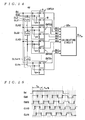
- FIG. 5 is a timing chart useful in explaining the operation of the pulse width calculating unit shown in FIG. 2;
- FIG. 9 is a timing chart useful in explaining the operation of the pulse width calculating unit shown in FIG. 7;
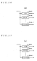
- FIG. 14 is a block diagram showing the construction of a pulse width calculating unit of a fourth radar apparatus
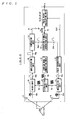
- the pulse width calculating unit 16 generates, based on the detection signal Sd that can be used to measure the distance L to the vehicle OB, (n-1) delayed detection signals S d2 , S d3 , ..., S dn whose phases are respectively shifted by Tc/n with respect to the detection signal S d .
- the respective pulse widths of the detection signal S d and the delayed detection signals S d2 , S d3 , ..., S dn are counted in synchronization with the internal clock CLK using the n counter circuits CNT11, CNT12, ..., CNT1n and the sum Dsum of the n count values D1, D2, ..., Dn found by this counting is calculated.
- the falling edges of the respective delayed detection signals S d2 to S d4 are included in a half cycle following the half cycle of the internal clock CLK in which the falling edge of the detection signal S d is included.
- the counter B of the counter circuit CNT22 carries out four count operations in the same way as the respective counters B in the counter circuits CNT23 and CNT24.
- the count values of the other counters A and B are 3.
- the count values D11, D12, D21, D22, ..., D41, D42 of the respective counters A, B outputted from the respective counter circuits CNT21 to CNT24 only the count values D22, D32, and D42 are 4, with the other count values being 3.
- the totals of the count values of the respective counters A, B outputted from the counter circuits CNT21 to CNT24 are each 6 for the counter circuits CNT21 and are 7 for the respective counter circuits CNT22, CNT23 and CNT24.
- the calculating circuit 22a calculates the sum Dsum of the count values D11 to D42 outputted from the respective counter circuits CNT21 to CNT24, multiplies the sum Dsum by Tc/(2 ⁇ 4), and further adds Tc/(4 ⁇ 4) to calculate the pulse width Tw of the detection signal S d . More specifically, when the pulse width of the detection signal S d is the length shown in FIG.
- the pulse width calculating unit 32 includes a delay circuit DL1, n counter circuits CNT11 to CNT1n, and a calculating circuit 16a, and calculates the pulse width Tw of the inputted detection signal S d .
- the delay circuit DL1 outputs (n-1) delayed internal clocks CLK2 to CLKn that are the internal clock CLK inputted from the delay element DL11 after the internal clock CLK has been delayed by Tc/(2 ⁇ n), 2 ⁇ Tc/(2 ⁇ n), ..., (n-1) ⁇ Tc/(2 ⁇ n), respectively.
Landscapes
- Engineering & Computer Science (AREA)
- Radar, Positioning & Navigation (AREA)
- Remote Sensing (AREA)
- Physics & Mathematics (AREA)
- General Physics & Mathematics (AREA)
- Computer Networks & Wireless Communication (AREA)
- Electromagnetism (AREA)
- Radar Systems Or Details Thereof (AREA)
- Traffic Control Systems (AREA)
Applications Claiming Priority (2)
| Application Number | Priority Date | Filing Date | Title |
|---|---|---|---|
| JP2003424518 | 2003-12-22 | ||
| JP2003424518A JP2005181180A (ja) | 2003-12-22 | 2003-12-22 | レーダ装置 |
Publications (1)
| Publication Number | Publication Date |
|---|---|
| EP1548460A1 true EP1548460A1 (de) | 2005-06-29 |
Family
ID=34544927
Family Applications (1)
| Application Number | Title | Priority Date | Filing Date |
|---|---|---|---|
| EP04030287A Ceased EP1548460A1 (de) | 2003-12-22 | 2004-12-21 | Radarvorrichtung |
Country Status (4)
| Country | Link |
|---|---|
| US (1) | US7280069B2 (de) |
| EP (1) | EP1548460A1 (de) |
| JP (1) | JP2005181180A (de) |
| KR (1) | KR100679528B1 (de) |
Cited By (3)
| Publication number | Priority date | Publication date | Assignee | Title |
|---|---|---|---|---|
| EP2546708A1 (de) * | 2011-07-15 | 2013-01-16 | Askey Technology (Jiangsu) Ltd. | Verfahren und System zum Messen des Abstands |
| EP2546657A1 (de) * | 2011-07-15 | 2013-01-16 | Askey Technology (Jiangsu) Ltd. | Verfahren und System zum Messen der Geschwindigkeit |
| EP2546709A1 (de) * | 2011-07-15 | 2013-01-16 | Askey Technology (Jiangsu) Ltd. | Verfahren und System zum Messen von Zeit |
Families Citing this family (25)
| Publication number | Priority date | Publication date | Assignee | Title |
|---|---|---|---|---|
| JP2005180992A (ja) * | 2003-12-17 | 2005-07-07 | Tdk Corp | レーダ装置 |
| JP2006064644A (ja) | 2004-08-30 | 2006-03-09 | Tdk Corp | パルス波レーダー装置 |
| WO2007083355A1 (ja) | 2006-01-17 | 2007-07-26 | Fujitsu Limited | レーダ装置及びその処理方法 |
| JP2008241695A (ja) | 2007-02-27 | 2008-10-09 | Fujifilm Corp | 測距装置及び測距方法 |
| JP2008209298A (ja) * | 2007-02-27 | 2008-09-11 | Fujifilm Corp | 測距装置及び測距方法 |
| JP5180501B2 (ja) * | 2007-03-23 | 2013-04-10 | 富士フイルム株式会社 | 測距装置及び測距方法 |
| JP5180502B2 (ja) * | 2007-03-23 | 2013-04-10 | 富士フイルム株式会社 | 測距装置及び測距方法 |
| JP2009031165A (ja) * | 2007-07-27 | 2009-02-12 | Toyota Motor Corp | パルスレーダ装置 |
| JP4895304B2 (ja) * | 2007-09-26 | 2012-03-14 | 富士フイルム株式会社 | 測距方法および装置 |
| JP5280030B2 (ja) * | 2007-09-26 | 2013-09-04 | 富士フイルム株式会社 | 測距方法および装置 |
| JP5021410B2 (ja) * | 2007-09-28 | 2012-09-05 | 富士フイルム株式会社 | 測距装置および測距方法並びにプログラム |
| JP2009085705A (ja) * | 2007-09-28 | 2009-04-23 | Fujifilm Corp | 測距装置および測距方法並びにプログラム |
| US8125620B2 (en) | 2007-10-18 | 2012-02-28 | PulsedLight, LLC | Optical sensor device |
| JP5436795B2 (ja) * | 2008-04-09 | 2014-03-05 | 日本無線株式会社 | レーダー受信波処理装置、及びレーダー装置 |
| JP5119501B2 (ja) * | 2009-11-12 | 2013-01-16 | 株式会社ネットコムセック | 周波数測定装置 |
| JP2012154856A (ja) * | 2011-01-27 | 2012-08-16 | Koko Res Kk | 周波数計測装置及び周波数位相差比較装置 |
| TWI481892B (zh) | 2012-12-13 | 2015-04-21 | Ind Tech Res Inst | 脈波雷達測距裝置及其測距演算法 |
| EP2916141B1 (de) * | 2014-03-06 | 2024-07-10 | Acconeer AB | Sender-Empfänger-System |
| CN104569620A (zh) * | 2014-12-30 | 2015-04-29 | 西安奇维科技股份有限公司 | 一种高精度数字脉宽采集的方法 |
| RU2607639C2 (ru) * | 2014-12-31 | 2017-01-10 | Федеральное государственное бюджетное учреждение "4 Центральный научно-исследовательский институт" Министерства обороны Российской Федерации | Способ определения дальности до объекта с источником излучения сигналов с разными частотами |
| RU2586622C1 (ru) * | 2015-08-24 | 2016-06-10 | Александр Абрамович Часовской | Устройство определения направления до импульсных излучателей |
| CN107422193B (zh) * | 2017-06-30 | 2023-09-15 | 成都信息工程大学 | 一种测量单粒子翻转瞬态脉冲长度的电路及方法 |
| US10533966B2 (en) | 2017-07-27 | 2020-01-14 | Taiwan Semiconductor Manufacturing Co., Ltd. | Digital time domain readout circuit for bioFET sensor cascades |
| RU2659818C1 (ru) * | 2017-12-25 | 2018-07-04 | Александр Абрамович Часовской | Устройство определения направления до импульсных излучателей |
| CN116125148A (zh) * | 2022-12-23 | 2023-05-16 | 天津兆讯电子技术有限公司 | 一种脉冲信号宽度检测电路及芯片 |
Citations (7)
| Publication number | Priority date | Publication date | Assignee | Title |
|---|---|---|---|---|
| US3264454A (en) * | 1962-09-24 | 1966-08-02 | Canoga Electronics Corp | Digital device for measuring time intervals |
| JPH06138230A (ja) * | 1992-10-28 | 1994-05-20 | Nec Corp | 測距装置 |
| JPH07244154A (ja) * | 1994-03-07 | 1995-09-19 | Mitsubishi Electric Corp | 車両用レーダ装置 |
| US5598116A (en) * | 1994-10-31 | 1997-01-28 | Daewoo Electronics, Co. Ltd. | Apparatus for measuring a pulse duration |
| JPH09304533A (ja) * | 1996-05-20 | 1997-11-28 | Omron Corp | 距離測定装置及び車両 |
| US5745442A (en) * | 1996-10-22 | 1998-04-28 | Power Spectra, Inc. | Digital time interval measurement engine for a time of flight system |
| US6137438A (en) * | 1998-07-22 | 2000-10-24 | Thomas E. McEwan | Precision short-range pulse-echo systems with automatic pulse detectors |
Family Cites Families (22)
| Publication number | Priority date | Publication date | Assignee | Title |
|---|---|---|---|---|
| US3666367A (en) * | 1970-06-01 | 1972-05-30 | Hughes Aircraft Co | Digital range measuring system |
| US4153366A (en) * | 1977-06-21 | 1979-05-08 | The Charles Stark Draper Laboratory, Inc. | Rangefinding system |
| US4150375A (en) * | 1978-03-02 | 1979-04-17 | Sperry Rand Corporation | Interferometric protective system for vehicles |
| CH641308B (de) * | 1982-07-13 | Wild Heerbrugg Ag | Vorrichtung zur laufzeitmessung von impulssignalen. | |
| JPS6243589A (ja) * | 1985-08-20 | 1987-02-25 | Meisei Electric Co Ltd | 時間計測方法 |
| SE465392B (sv) * | 1990-01-12 | 1991-09-02 | Optab Optronikinnovation Ab | Foerfarande och anordning vid optiska avstaandsmaetare |
| JP2517876Y2 (ja) * | 1990-04-23 | 1996-11-20 | 日本航空電子工業株式会社 | ホモダイン方式電波測距装置 |
| JPH05249260A (ja) * | 1992-03-06 | 1993-09-28 | Seiko Epson Corp | 時間計測方法 |
| JPH07280940A (ja) * | 1994-04-12 | 1995-10-27 | Mitsubishi Electric Corp | 車両用レーダ装置 |
| US5612779A (en) * | 1995-01-19 | 1997-03-18 | Laser Technology, Inc. | Automatic noise threshold determining circuit and method for a laser range finder |
| US5574552A (en) * | 1995-01-19 | 1996-11-12 | Laser Technology, Inc. | Self-calibrating precision timing circuit and method for a laser range finder |
| JPH0921873A (ja) * | 1995-07-04 | 1997-01-21 | Koito Mfg Co Ltd | 距離測定装置 |
| JP2793524B2 (ja) * | 1995-07-31 | 1998-09-03 | 日本電気アイシーマイコンシステム株式会社 | 時間測定システムおよびその測定方法 |
| JPH1048338A (ja) * | 1996-05-20 | 1998-02-20 | Olympus Optical Co Ltd | 距離測定装置 |
| JP3123931B2 (ja) * | 1996-08-29 | 2001-01-15 | 日本電気アイシーマイコンシステム株式会社 | 時間測定システム及びその時間測定方法 |
| JP3757557B2 (ja) * | 1997-07-23 | 2006-03-22 | 株式会社デンソー | 距離測定装置 |
| EP0933649A3 (de) * | 1998-01-28 | 2002-03-27 | Nikon Corporation | Entfernungsmessgerät |
| JP3899708B2 (ja) * | 1998-10-16 | 2007-03-28 | 株式会社デンソー | 距離測定装置 |
| JP4857466B2 (ja) * | 2001-01-18 | 2012-01-18 | 株式会社デンソー | 時間測定装置及び距離測定装置 |
| US6771103B2 (en) * | 2001-03-14 | 2004-08-03 | Denso Corporation | Time measurement apparatus, distance measurement apparatus, and clock signal generating apparatus usable therein |
| JP4457525B2 (ja) * | 2001-06-11 | 2010-04-28 | 株式会社デンソー | 距離測定装置 |
| JP2006064644A (ja) * | 2004-08-30 | 2006-03-09 | Tdk Corp | パルス波レーダー装置 |
-
2003
- 2003-12-22 JP JP2003424518A patent/JP2005181180A/ja active Pending
-
2004
- 2004-11-30 KR KR1020040099343A patent/KR100679528B1/ko not_active Expired - Fee Related
- 2004-12-21 EP EP04030287A patent/EP1548460A1/de not_active Ceased
- 2004-12-21 US US11/016,973 patent/US7280069B2/en not_active Expired - Fee Related
Patent Citations (7)
| Publication number | Priority date | Publication date | Assignee | Title |
|---|---|---|---|---|
| US3264454A (en) * | 1962-09-24 | 1966-08-02 | Canoga Electronics Corp | Digital device for measuring time intervals |
| JPH06138230A (ja) * | 1992-10-28 | 1994-05-20 | Nec Corp | 測距装置 |
| JPH07244154A (ja) * | 1994-03-07 | 1995-09-19 | Mitsubishi Electric Corp | 車両用レーダ装置 |
| US5598116A (en) * | 1994-10-31 | 1997-01-28 | Daewoo Electronics, Co. Ltd. | Apparatus for measuring a pulse duration |
| JPH09304533A (ja) * | 1996-05-20 | 1997-11-28 | Omron Corp | 距離測定装置及び車両 |
| US5745442A (en) * | 1996-10-22 | 1998-04-28 | Power Spectra, Inc. | Digital time interval measurement engine for a time of flight system |
| US6137438A (en) * | 1998-07-22 | 2000-10-24 | Thomas E. McEwan | Precision short-range pulse-echo systems with automatic pulse detectors |
Non-Patent Citations (1)
| Title |
|---|
| PATENT ABSTRACTS OF JAPAN vol. 1996, no. 01 31 January 1996 (1996-01-31) * |
Cited By (3)
| Publication number | Priority date | Publication date | Assignee | Title |
|---|---|---|---|---|
| EP2546708A1 (de) * | 2011-07-15 | 2013-01-16 | Askey Technology (Jiangsu) Ltd. | Verfahren und System zum Messen des Abstands |
| EP2546657A1 (de) * | 2011-07-15 | 2013-01-16 | Askey Technology (Jiangsu) Ltd. | Verfahren und System zum Messen der Geschwindigkeit |
| EP2546709A1 (de) * | 2011-07-15 | 2013-01-16 | Askey Technology (Jiangsu) Ltd. | Verfahren und System zum Messen von Zeit |
Also Published As
| Publication number | Publication date |
|---|---|
| US20050134498A1 (en) | 2005-06-23 |
| US7280069B2 (en) | 2007-10-09 |
| KR20050063677A (ko) | 2005-06-28 |
| JP2005181180A (ja) | 2005-07-07 |
| KR100679528B1 (ko) | 2007-02-07 |
Similar Documents
| Publication | Publication Date | Title |
|---|---|---|
| EP1548460A1 (de) | Radarvorrichtung | |
| US5686921A (en) | Radar system | |
| Jansson et al. | A multichannel high-precision CMOS time-to-digital converter for laser-scanner-based perception systems | |
| US5724041A (en) | Spread spectrum radar device using pseudorandom noise signal for detection of an object | |
| US6771103B2 (en) | Time measurement apparatus, distance measurement apparatus, and clock signal generating apparatus usable therein | |
| EP2000810B1 (de) | Bestimmung der Sinusperiode | |
| US20040100626A1 (en) | Method and device for operating a pmd system | |
| CN107843903B (zh) | 一种多阀值tdc高精度激光脉冲测距方法 | |
| CN112994690A (zh) | 时间-数字转换器以及转换方法 | |
| CN101080646B (zh) | 电子测量方法 | |
| JP2008524562A5 (de) | ||
| EP3680683B1 (de) | Sensorvorrichtung und messverfahren | |
| US6859165B2 (en) | Pulse radar device | |
| JP2013205092A (ja) | 時間測定装置 | |
| JP2007033287A (ja) | パルス波レーダー装置 | |
| JP5654253B2 (ja) | 障害物検知装置 | |
| JP4754981B2 (ja) | パルスレーダ装置 | |
| JP3453341B2 (ja) | レーダ装置 | |
| JPH04363687A (ja) | 測距方式 | |
| US20080267016A1 (en) | Electric Counter Circuit | |
| JPH09318738A (ja) | レーダ装置 | |
| JPS6293677A (ja) | 障害物検知装置 | |
| CN118707539A (zh) | 一种便于提高速度和精度的激光测距仪 | |
| CN121008251A (zh) | 一种回波信号接收方法、装置、终端设备及存储介质 | |
| RU2007753C1 (ru) | Корреляционная измерительная система |
Legal Events
| Date | Code | Title | Description |
|---|---|---|---|
| PUAI | Public reference made under article 153(3) epc to a published international application that has entered the european phase |
Free format text: ORIGINAL CODE: 0009012 |
|
| AK | Designated contracting states |
Kind code of ref document: A1 Designated state(s): AT BE BG CH CY CZ DE DK EE ES FI FR GB GR HU IE IS IT LI LT LU MC NL PL PT RO SE SI SK TR |
|
| AX | Request for extension of the european patent |
Extension state: AL BA HR LV MK YU |
|
| 17P | Request for examination filed |
Effective date: 20051004 |
|
| AKX | Designation fees paid |
Designated state(s): DE FR GB IT SE |
|
| STAA | Information on the status of an ep patent application or granted ep patent |
Free format text: STATUS: THE APPLICATION HAS BEEN REFUSED |
|
| 18R | Application refused |
Effective date: 20080712 |