EP1531629A1 - Bildverarbeitungssystem - Google Patents
Bildverarbeitungssystem Download PDFInfo
- Publication number
- EP1531629A1 EP1531629A1 EP03771304A EP03771304A EP1531629A1 EP 1531629 A1 EP1531629 A1 EP 1531629A1 EP 03771304 A EP03771304 A EP 03771304A EP 03771304 A EP03771304 A EP 03771304A EP 1531629 A1 EP1531629 A1 EP 1531629A1
- Authority
- EP
- European Patent Office
- Prior art keywords
- image
- light
- spectroscopic
- subject
- processing system
- Prior art date
- Legal status (The legal status is an assumption and is not a legal conclusion. Google has not performed a legal analysis and makes no representation as to the accuracy of the status listed.)
- Withdrawn
Links
Images


Classifications
-
- A—HUMAN NECESSITIES
- A61—MEDICAL OR VETERINARY SCIENCE; HYGIENE
- A61B—DIAGNOSIS; SURGERY; IDENTIFICATION
- A61B5/00—Measuring for diagnostic purposes; Identification of persons
-
- H—ELECTRICITY
- H04—ELECTRIC COMMUNICATION TECHNIQUE
- H04N—PICTORIAL COMMUNICATION, e.g. TELEVISION
- H04N23/00—Cameras or camera modules comprising electronic image sensors; Control thereof
- H04N23/56—Cameras or camera modules comprising electronic image sensors; Control thereof provided with illuminating means
-
- H—ELECTRICITY
- H04—ELECTRIC COMMUNICATION TECHNIQUE
- H04N—PICTORIAL COMMUNICATION, e.g. TELEVISION
- H04N23/00—Cameras or camera modules comprising electronic image sensors; Control thereof
- H04N23/60—Control of cameras or camera modules
- H04N23/63—Control of cameras or camera modules by using electronic viewfinders
-
- H—ELECTRICITY
- H04—ELECTRIC COMMUNICATION TECHNIQUE
- H04N—PICTORIAL COMMUNICATION, e.g. TELEVISION
- H04N23/00—Cameras or camera modules comprising electronic image sensors; Control thereof
- H04N23/60—Control of cameras or camera modules
- H04N23/667—Camera operation mode switching, e.g. between still and video, sport and normal or high- and low-resolution modes
-
- H—ELECTRICITY
- H04—ELECTRIC COMMUNICATION TECHNIQUE
- H04N—PICTORIAL COMMUNICATION, e.g. TELEVISION
- H04N23/00—Cameras or camera modules comprising electronic image sensors; Control thereof
- H04N23/80—Camera processing pipelines; Components thereof
- H04N23/84—Camera processing pipelines; Components thereof for processing colour signals
-
- H—ELECTRICITY
- H04—ELECTRIC COMMUNICATION TECHNIQUE
- H04N—PICTORIAL COMMUNICATION, e.g. TELEVISION
- H04N25/00—Circuitry of solid-state image sensors [SSIS]; Control thereof
- H04N25/10—Circuitry of solid-state image sensors [SSIS]; Control thereof for transforming different wavelengths into image signals
- H04N25/11—Arrangement of colour filter arrays [CFA]; Filter mosaics
-
- H—ELECTRICITY
- H04—ELECTRIC COMMUNICATION TECHNIQUE
- H04N—PICTORIAL COMMUNICATION, e.g. TELEVISION
- H04N25/00—Circuitry of solid-state image sensors [SSIS]; Control thereof
- H04N25/40—Extracting pixel data from image sensors by controlling scanning circuits, e.g. by modifying the number of pixels sampled or to be sampled
- H04N25/44—Extracting pixel data from image sensors by controlling scanning circuits, e.g. by modifying the number of pixels sampled or to be sampled by partially reading an SSIS array
Definitions
- the present invention relates to an image processing system, and more particularly, to an image processing system which captures a spectroscopic image of a subject and performs the processing color reproduction of the subject with high precision.
- a camera system is used for the skin check which observes the skin surface on a monitor by enlarging it.
- the camera system for skin check is used in the dermatology, esthetic salon, beauty counseling, and the like.
- the pecuriality of the skin surface is checked by observing an image of the crista cutis or sulcus cutis and then the counseling is performed.
- Japanese Unexamined Patent Application Publication No. 8-149352 discloses one camera for skin check.
- a skin observing apparatus comprises: a case having the opening in front thereof; an optical system having an optical axis as the center of the opening arranged in the case; a solid-state image pick-up device which forms an optical image from the optical system on an image pick-up surface; and a plurality of light-emitting devices which are arranged to illuminate a subject out of the opening via the opening from the inside of the case, have the light illumination in the direction to the opening, are arranged like a ring with the optical axis as the center, and have blue luminescent color.
- Japanese Unexamined Patent Application Publication No. 7-322103 discloses another camera for skin check comprising: a lens which is arranged in a case, facing an image pick-up window opened in front of a case main body; an image pick-up device which picks-up an optical image incident via the lens; a circular-line fluorescent lamp which is arranged in the case and illuminates the image pick-up window; a reflecting unit which adjusts an advancing angle by the reflection upon guiding illuminating light from the circular-line fluorescent lamp; a transparent sliding pipe which is arranged coaxially to the image pick-up window in the case with the same diameter as that of the circumference of the image pick-up window and is freely movable in the axial direction; and a shading ring unit which is attached to a part of the transparent sliding pipe and realizes a first state and a second state.
- the first state permits the passage of the illuminating light from the circular-line fluorescent lamp via a transparent portion of the transparent sliding pipe in response to the movement of the transparent sliding pipe in the axial direction and which prohibits the passage of the illuminating light from the circular-line fluorescent lamp via the reflecting unit.
- the second state permits the passage of the illuminating light from the circular-line fluorescent lamp via the reflecting unit and which prohibits the passage of the illuminating light from the fluorescent lamp of the image pick-up window via the transparent sliding pipe.
- the dentistry needs to finish the color with the sense of comfort to the patient teeth in the case of creating a prosthetic tooth.
- data on the teeth color is obtained with the subjectivity by the direct comparison with the patient teeth color by using a shading guide.
- the paint color of a vehicle and a building, the spectroscopic characteristics of food, and the dyeing of cloths require a technology for reproducing the color of the subject with accuracy for the purpose of using on the diagnosis, examination, confirmation, and determination.
- Japanese Unexamined Patent Application Publication No. 2000-152269 discloses a color reproducing system in which multi-band image data is captured by picking-up an image of a subject under exterior lighting with many spectroscopic filters arranged on a rotary filter turret and further the color is reproduced by estimating the spectroscopic spectrum of the subject with high accuracy.
- the color reproducing system disclosed in the Japanese Unexamined Patent Application Publication No. 2000-152269 is used to obtain spectrum data of the subject in a laboratory or the like, with the heavy weight in the fixing type, and needs another illuminating sensor which is used for the color reproduction with the exterior lighting.
- the above-mentioned fields of users, for whom the compact size, light weight, and handy property are necessary for the operation do not satisfy with the conventional color reproducing system.
- the dermatology conventionally uses a handy-type image processing system that does not obtain the multi-band data. Therefore, the handy-type image processing system does not satisfy the need for color reproduction with high precision.
- an image processing system comprises: a photographing apparatus; and a processing apparatus.
- the photographing apparatus comprises: a plurality of light-emitting devices for illuminating a subject, the plurality of light-emitting devices respectively emit light having the independent and different characteristics of spectroscopic distributions at least in a visible-light area; an image pick-up optical system which forms a subject image illuminated by the light-emitting devices; an image pick-up device unit which picks-up the subject image formed by the image pick-up optical system and outputs an image signal; and a control unit which controls an operation for capturing a plurality of subject spectroscopic images by selectively lighting-on the plurality of light-emitting devices in accordance with the characteristics of the spectroscopic distributions and by varying the selection of the plurality of light-emitting devices with the synchronization of the light-on operation and the operation for picking-up the image by the image pick-up device by a plurality of times.
- the processing apparatus comprises: a plurality of
- the control unit sets a group comprising a plurality of devices comprising at least one light-emitting device from among the plurality of light-emitting devices in accordance with the characteristics of the spectroscopic distributions, determines the light-on sequence of the plurality of devices in the set group, lights-on the light-emitting devices in the devices in accordance with the light-on sequence for selective light-on operation, and controls the plurality of spectroscopic images.
- control unit sets a plurality of types of the groups and controls the operation for using the set groups necessary for application.
- the control unit sets a group of the light-emitting groups comprising the light-emitting devices of blue in the visible light area, the light-emitting devices of red in the visible light area, and the light-emitting devices of green in the visible light area, among from the plurality of light-emitting devices, sequentially lights-on the light-emitting devices of the group every image pick-up frame, and controls the operation for picking-up a three-primary-color moving image by the image pick-up device unit.
- the photographing apparatus further comprises: a photographing operating unit which inputs at least an instruction for starting a spectroscopic image photographing operation.
- the control unit controls the operation for capturing the plurality of subject spectroscopic images in accordance with the input of the instruction for starting the spectroscopic image photographing operation from the photographing operating unit.
- the photographing operating unit comprises a pressing button switch
- the control unit controls the operation for changing the group upon pressing the button switch.
- control unit controls light-on timings of the devices of the changed group, upon pressing the button switch.
- control unit controls the operation for starting the image pick-up operation by the image pick-up device unit after starting the light-on operation of the light-emitting device and for ending it before lighting-off the light-emitting device.
- the image pick-up device unit comprises: a spectroscopic unit which performs the spectroscopy on incident light to make it into light with a plurality of wavelengths; and a plurality of image pick-up devices which pick-up the light with the plurality of wavelengths subjected to the spectroscopy by the spectroscopic unit.
- the image pick-up device unit comprises a color image pick-up device having a color filter array.
- the photographing apparatus further comprises: a spectrum sensor which senses the characteristics of the spectroscopic distributions of the light-emitting devices.
- the photographing apparatus further comprises a spectrum sensor which senses the characteristic of the spectroscopic distribution of ambient light.
- the photographing apparatus further comprises an abutting portion which is abutted to the subject at one end thereof.
- the abutting portion comprises a flexible material with cylindrical shape.
- the abutting portion comprises a material which rejects or reduces the influence from ambient light.
- the abutting portion is detachable to a casing of the photographing apparatus.
- the processing apparatus further comprises an image memory unit which stores the subject spectroscopic image photographed by the photographing apparatus, and the calculating unit calculates a desired image based on the image signal stored in the image memory unit.
- the calculating unit calculates a signal for displaying the subject image which is color-reproduced at the high fidelity level based on the subject spectroscopic image stored in the image memory unit.
- the processing apparatus calculates profile information necessary for calculating the signal for displaying the subject image which is color-reproduced at the high fidelity level based on the data captured by the photographing apparatus.
- the calculating unit determines or analyzes the subject based on the subject spectroscopic image stored in the image memory unit and outputs the determining or analyzing result.
- the image pick-up device unit changes a frame rate for the image pick-up operation.
- the photographing apparatus further comprises a photographing operating unit for inputting at least an instruction for starting the spectroscopic image photographing operation, and the control unit controls the operation for capturing the plurality of subject spectroscopic images in accordance with the input of the instruction for starting the operation for photographing the spectroscopic image from the photographing operating unit.
- Figs. 1 to 16 relate to a first embodiment
- Fig. 1 is a block diagram showing the configuration of an image processing system.
- the image processing system comprises: a photographing apparatus 1 which can take a picture of a subject spectroscopic image by illuminating a subject with illuminating light having a plurality of independent varying wavelength bands in a visible light area; and a processing apparatus 2 which is connected to the photographing apparatus 1 and processes the subject spectroscopic image outputted from the photographing apparatus 1.
- the processing apparatus 2 is connected to a network 3 if necessary.
- the image pick-up operation of a still image and the image pick-up operation of a moving image are performed. That is, in the image pick-up operation of the still image, illuminating light having six types of wavelength bands (six primary-color illuminating light) is sequentially irradiated to the subject, and six subject-spectroscopic-images are captured as the still images.
- the image pick-up operation of the moving image at least one piece of illuminating light is selected from the six primary-color illuminating light, three R-, G-, and B-illuminating light is set and is sequentially irradiated, and the images are captured as a surface-sequential moving image.
- the photographing apparatus 1 comprises: a casing 5 having a projecting port 5a which projects the illuminating light, as will be described later, and on which reflecting light from the subject is incident; an abutting portion 4 which is detachably attached to the projecting port 5a of the casing 5 and is cylindrically-shaped, containing a material with the flexibility for shielding so as to prevent the mixing the ambient light and the illuminating light projected to the subject via the projecting port 5a; first to sixth LEDs 6a to 6f serving as light-emitting devices which are built-in the casing 5 and emit the illuminating light by the light-on so as to illuminate the subject; an image pick-up optical system 7 which is built-in the casing 5 and creates a subject image illuminated by the first to sixth LEDs 6a to 6f; a CCD 8 serving as an image pick-up device, included in an image pick-up device unit which picks-up the subject image formed by the image pick-up optical system 7 and outputs an image signal; an
- the processing apparatus 2 comprises: a calculating device 21 which comprises, e.g., a personal computer or the like, receives the subject spectroscopic image outputted from the external I/F 17, calculates three XYZ excitation values by using an input profile as will be described later, and generates a display signal for obtaining, from a display 22 that will be described later, substantially the same three XYZ excitation values as the three XYZ excitation values presumed to be given by the subject with a display profile based on the calculated three XYZ excitation values; and the display 22 which displays the image on which the colors are reproduced at the high fidelity level by using the display signal outputted from the calculating device 21.
- the processing apparatus 2 comprises a network interface for connecting to the network 3 and the like.
- the photographing apparatus 1 and the processing apparatus 2 may be connected by wiring.
- the photographing apparatus 1 and the processing apparatus 2 may be connected by radio frequency using Bluetooth or radio LAN or may be integrally configured.
- Fig. 3 is a graph showing the spectroscopic sensitivity characteristics of the CCD 8, the light-emitting spectrums of the first to sixth LEDs 6a to 6f, and the spectroscopic characteristics thereof.
- the first to sixth LEDs 6a to 6f serving as the light-emitting devices have varied independent light-emitting spectrums.
- the light of the first LED 6a shown by a curve fL1 is blue having the small amount of violet, for example.
- the light of the second LED 6b shown by a curve fL2 is blue having the small amount of green, for example.
- the light of the third LED 6c shown by a curve fL3 is green having the small amount of blue, for example.
- the light of the fourth LED 6d shown by a curve fL4 is green having the small amount of yellow, for example.
- the light of the fifth LED 6e shown by a curve fL5 is orange, for example.
- the light of the sixth LED 6f shown by a curve fL6 is red, for example.
- the light-emitting spectrums of the first to sixth LEDs 6a to 6f are completely separated without overlaying each other.
- the light-emitting spectrums of the first to sixth LEDs 6a to 6f may be partly overlaid.
- the number of types of LEDs is not limited to six and an arbitrary number of types of LEDs may be properly combined.
- the spectrums of the illuminating light of the LEDs may be arrayed at an equal wavelength interval (at which peaks, for example, are aligned at an equal interval in the wavelength direction), at an equal wavelength ratio interval (at which the peaks or the like are aligned at a predetermined ratio interval in the wavelength direction), at a specific array for specific purpose (by which the peaks or the like are specifically aligned in the wavelength direction for the specific purpose), by the setting to be sequentially multiplying a specific wavelength-color (by which the peaks or the like are aligned at the position for sequentially multiplying the wavelength by using the specific wavelength as a basic wavelength), by the arrangement of a specific polarizing color (by which the blight expressed by the peaks aligned in the wavelength direction is polarized in the specific direction), or by the arrangement of light extended to outside the visible light area (by which the light expressed by the peaks aligned in the wavelength direction reaches an area outside the visible light area).
- the spectrum alignment matching the using purpose may be selected.
- the light-emitting device uses the LED serving as a semiconductor light-emitting device with high luminance that is light in weight, compact in size, and is easily obtained because of its relatively inexpensive price.
- the light-emitting device is not limited to this and may be a semiconductor laser such as an LD (laser diode) or another light-emitting device.
- the CCD 8 is a monochrome-type one. As shown by a curve fS in Fig. 3(A), the sensor sensitivity entirely covers the visible light area.
- the image pick-up device uses a monochrome-type CCD. However, the image pick-up device is not limited to this and may use a color-type CCD as will be described later, a CMOS-type CCD, or other image pick-up devices.
- curves fSL1 to fSL6 show the spectroscopic sensitivity characteristics, when the CCD 8 receives the light of the subject images illuminated by the first to sixth LEDs 6a to 6f.
- the difference of wavelengths having the total spectroscopic sensitivity characteristics is electrically processed later or is corrected as the input profile of the photographing apparatus 1.
- Fig. 2 is a diagram showing an example configuration and an example of the arrangement of the LEDs.
- the first to sixth LEDs 6a to 6f comprise six primary colors. Three sets of the first to sixth LEDs 6a to 6f (three sets for each color) are sequentially arranged like a ring.
- the arranging sequence shown in Fig. 2(A) is one example, the present invention is not limited to this and can be widely applied to an arbitrary arrangement such as inverse sequence and random arrangement.
- a plurality of light-emitting portions 6A are arranged like a ring.
- the first to sixth LEDs 6a to 6f are arranged such that the light-emitting portions 6A include the six primary colors.
- one light-emitting portion 6A includes all the six primary colors, but the present invention is not limited to this and the six primary colors are separately arranged to a plurality of light-emitting portions 6A, e.g., three primary colors are arranged to the two light-emitting portions 6A.
- one ends 6Ba to 6Bf of a fiber bundle 6B are connected to the first to sixth LEDs 6a to 6f and the other end 6Bg of the fiber bundle 6B is formed like a ring.
- the bundle fiber end comprises a plurality of fine fibers.
- the fine fibers of the LEDs are mixed and thus the light is irradiated to the subject by using the fibers as an even light source like a ring. The influence of total reflection from the subject is suppressed.
- the arrangement of the LEDs is not limited to the examples shown in Fig. 2. As long as the CCD 8 does not disturb the image pick-up operation, the arrangement of the LEDs can may be like a ring one, cross one, rectangular one, random one, and another proper one.
- the photographing apparatus 1 picks-up the moving image as the normal RGB images and the still image as the subject spectroscopic images of the six primary colors for reproducing the color at the high fidelity level.
- the moving image is picked-up.
- the still image is picked-up.
- the two modes are switched by pressing a photographing button 14a (refer to Fig. 16) comprising a pressing button switch included in the operating switch 14.
- the capturing mode of the monitoring image is automatically set by switching-on a power switch, and the subject image is displayed on the LED monitor 16 as the moving image.
- the portion in the subject for photographing the spectroscopic image is searched and the photographing apparatus 1 is positioned.
- the portion in the subject to be photographed is within the image pick-up range and the photographing apparatus 1 is positioned.
- the photographing button 14a (refer to Fig. 16)
- the capturing mode of the monitoring image is switched to the capturing mode of the spectroscopic image and the subject spectroscopic image is captured as the still image.
- the mode is returned to the capturing mode of the monitoring image and the portion in the subject for next capturing spectroscopic image is searched.
- a result of analyzing the spectroscopic image or the color reproduction using the captured spectroscopic image is displayed on the LCD monitor 16 or the display 22 by another setting just after capturing the spectroscopic image.
- Fig. 4 is a flowchart showing the operations for light emission of LEDs and for image capturing by the image pick-up device upon capturing the 6-band spectroscopic images.
- Fig. 5 is a timing chart showing a state of the operations for light emission of the LEDs and for image capturing by the image pick-up device upon capturing the 6-band spectroscopic images.
- Fig. 6 is a graph showing the band characteristics of the frames upon capturing the 6-band spectroscopic images.
- step S1 By pressing the photographing button 14a (refer to Fig. 16), the capturing mode of the monitoring image is switched to the capturing mode of the spectroscopic image and then it is determined whether or not the image pick-up operation of the spectroscopic image starts (step S1).
- the photographing button 14a comprises a two-step pressing button and adjusts the focusing or the amount of exposure at the first pressing step serving as half pressing and starts the exposure at the second pressing step serving as the complete pressing, in step S1, it is determined whether or not the operation is to be executed at the second pressing step.
- step S2 one is set to a variable n (step S2) and the n-th LED is lit-on (step S3). Since n is set to 1, the first LED 6a is lit-on.
- the illumination light using the first LED 6a is irradiated to the subject via the projecting port 5a of the casing 5.
- the abutting portion 4 is softly abutted to the subject surface so as to prevent the flow-in of the ambient light, the only the illumination light from the first LED 6a is projected to the subject.
- the reflecting light from the subject is formed onto the CCD 8 by using the image pick-up optical system 7.
- step S4 After starting the light-on operation of the first LED 6a, the image pick-up operation of the CCD 8, specifically, the storaging of charges starts (refer to Fig. 5) (step S4).
- the first LED 6a is lit-off (step S5).
- the image data is read from the CCD 8, is converted into digital data by the A/D converter 9, and is stored in a predetermined storage area (n-th memory, here, first memory) in the memory 11 (step S6).
- n-th memory here, first memory
- the memory 11 has the storage areas serving as the first to sixth memories, and the spectroscopic images are sequentially stored in the storage areas.
- variable n is incremented (step S7).
- the variable n is incremented from one to two.
- step S8 It is determined whether or not the variable n is seven or more (step S8). Since the variable n is 2 yet here, the processing returns to step S3 whereupon the second LED 6b is lit-on. After that, the operation in steps S3 to S7 is performed.
- step S6 After the sixth LED 6f is lit-on when the variable n is 6 and the operation to step S6 ends, the 6-band spectroscopic image is captured as shown in Fig. 6 and is stored in the memory 11.
- step S7 the variable n is incremented to 7, then, in step S8, it is determined that the variable n reaches 7 and the operation for capturing the 6-band spectroscopic images ends.
- the image capturing timings by the LEDs and the CCD are not limited to the foregoing. Identically, the LEDs are lit-on after starting capturing the image by the image pick-up device and the image capturing by the image pick-up device ends after the LEDs are lit-off
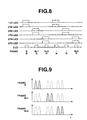
- Fig. 7 is a flowchart showing the operation for light emission of the LEDs and for image capturing by the image pick-up device upon capturing the monitoring image.
- Fig. 8 is a timing showing a state of the operation for light emission of the LEDs and for image capturing by the image pick-up device upon capturing the monitoring image.
- Fig. 9 is a graph showing the band characteristics of the frames upon capturing the monitoring image.
- the first LED 6a and the second LED 6b emit the light corresponding to the range of blue (B)
- the third LED 6c and the fourth LED 6d emit the light corresponding to the range of green (G)
- the fifth LED 6e and the sixth LED 6f emit the light corresponding to the range of red (R), thereby capturing the RGB images serving as the moving image by the surface sequential method.
- the primary colors of the light emission are selected for using on general RGB images.
- the present invention is not limited to this and another primary color of the light emission may be selected for using on specific application.
- the capturing mode of the monitoring image is set by switching-on the power switch or the mode is returned to the capturing mode of the monitoring image by ending the capturing mode of the spectroscopic image. Then, the start of the image pick-up operation of the monitoring image is waited (step S11).
- the image pick-up operation promptly starts and the variable n is set to one (step S12).
- the n-th LED and the (n+1)-th LED are lit-on (step S13). Since the variable n is set to one, the first LED 6a and the second LED 6b are lit-on.
- step S14 After starting the light-on operation of the first LED 6a and the second LED 6b, the image pick-up operation by the CCD 8 starts (refer to Fig. 8) (step S14).
- the first LED 6a and the second LED 6b are lit-off (step S15).
- the image data is read from the CCD 8, is converted into the digital data by the A/D converter 9, and is stored in a predetermined storage area (n-th memory, here, first memory) in the memory 11 via the bus 10 (step S16).
- variable n is increased by two (step S17).
- the variable n is increased from 1 to 3.
- step S18 It is determined whether or not the variable n is 7 or more (step S18).
- the processing returns to step S13 whereupon the third LED 6c and the fourth LED 6d are lit-on.
- the operation in steps S13 to S17 is performed.
- variable n is 5 and further the processing returns to step S13 whereupon the fifth LED 6e and the sixth LED 6f are lit-on.
- the operation to step S16 ends.
- the RGB images with the band characteristics shown in Fig. 9 are sequentially captured in order of R, G, and B, and are stored in the first memory, third memory, and fifth memory in the memory 11.
- the variable n is incremented to 7 in step S17 and therefore it is determined in step S18 that the variable n reaches 7.
- step S11 After capturing the RGB images, the processing returns to step S11 whereupon it is determined whether or not the next RGB images are captured.
- the capturing mode of the monitoring image is sequentially set, the next RGB images are captured. This operation is repeated, thereby capturing the RGB moving images.
- the image capturing timings of the LEDs and CCD are not limited to this. Identically, the LEDs are lit-on after starting capturing the image by the image pick-up device and the operation for capturing the image by the image pick-up device ends after lighting-off the LEDs.
- the above-mentioned image data stored in the memory 11 is then read, is converted into the image signal for display on the monitor, and is outputted and displayed on the LCD monitor 16 via the monitor I/F 15. Further, the setting of the image processing system is changed, thereby displaying the image data on the display 22 of the processing apparatus 2.
- the LEDs for the six primary colors are divided into three groups including the two LEDs, namely, R devices, G devices, and B devices.
- the LED for one primary color may be emitted for the light, specifically, the first LED 6a may be emitted with respect to the light B (blue), the third LED 6c may emit the light G (green), and the fifth LED 6e may be emitted with respect to the light R (red).
- the LED may be selected such that the spectroscopic characteristics of the LEDs match the RGB light emission.
- Only the LED for one primary color or the LEDs for a plurality of primary colors may be lit-on, thereby capturing a monochrome monitoring image. Consequently, the image can be displayed at a high speed on the monitor.
- Fig. 10 is a diagram showing an example of lighting-on the LEDs when the three LEDs for each of six primary colors are arranged.
- the light-emitting mode includes a case of lighting-on all the LEDs, a case of lighting-on one LED for one primary color, a case of lighting-on the three LEDs for one primary color, a case of lighting-on the LEDs for six primary colors one by one, a case of lighting-on the six LEDs of blue (B) in the eighteen LEDs for six primary colors, a case of lighting-on the six LEDs of green (G) in the eighteen LEDs for six primary colors, a case of lighting-on the six LEDs of red (R) in the eighteen LEDs for six primary colors, a case of lighting-on the three LEDs of blue (B) in the eighteen LEDs for six primary colors, a case of lighting-on the three LEDs of green (G) in the eighteen LEDs for six primary colors, or a case of lighting-on the three LEDs of red (R) in the eighteen LEDs for six primary colors.
- the devices for each color simultaneously emit the light and the devices collected at
- the photographing apparatus 1 picks-up the image of the subject either on contact or on noncontact with the subject. However, in order to accurately reproduce the image, it is necessary to prevent the influence from the light generated by devices other than the photographing apparatus 1.
- the illumination of the exterior lighting needs to be lit-off.
- the abutting portion 4 that is cylindrically shaped is softly abutted to the subject (refer to Fig. 1) as mentioned above. The shielding performance is ensured.
- the abutting portion 4 Since the abutting portion 4 is used in the image pick-up operation in the contact state, referring to Fig. 11, the abutting portion 4 is detachable and disposable member in view of the sanitation for preventing the bacterial contamination or dirt when the subject is the human body and in view of preventing the transfer of dirt when the subject is a painting plate.
- Fig. 11 is a perspective view showing the abutting portion 4 that is detachable to the projecting port 5a of the casing 5.
- the abutting portion 4 contains a heat insulator when the subject is at the high temperature or low temperature, an electric insulator when the subject is electrostatic or conductive, a solution-proof material when the subject is dipped in the solution, or a glass window for projecting the illuminating light and receiving the reflecting light. Since the abutting portion 4 is a single detachable part, the abutting portion 4 is easily formed, including the various above-mentioned materials. Further, an observing window that is opened and is closed to the abutting portion 4 is easily arranged to observe the subject surface by the naked eyes.
- one specific primary color or a plurality of primary colors are used from among the plurality of primary colors whose light is emitted by the LEDs, thereby enabling the use for the examination or determination for specific application.
- the subject spectroscopic image is recorded to the memory 11 by the image pick-up operation of the photographing apparatus 1, is sent to the processing apparatus 2 via the external I/F 17, and is recorded to an image memory unit 32 (refer to Fig. 12) incorporated in the processing apparatus 2. Then, the calculating device 21 that is operated by predetermined software performs the color reproduction or image processing of the recorded image.
- the processing result is displayed on the display 22 of the processing apparatus 2 or is transferred and is displayed on the LCD monitor 16.
- Fig. 12 is a block diagram showing the configuration for performing color reproduction to display on the display 22 in the processing apparatus 2.
- the processing apparatus 2 comprises: an image distributing unit 31 which distributes the storage areas in the image memory unit 32 depending on which of the first to sixth LEDs 6a to 6f illuminates the subject spectroscopic images inputted from the photographing apparatus 1; the image memory unit 32 having first to sixth memories 32a to 32f serving as the storage memories for storing the subject spectroscopic images distributed by the image distributing unit 31; and a color reproduction calculating unit 33 which reads the subject spectroscopic image stored in the image memory unit 32 and calculates and outputs display image data for displaying the image that is color-reproduced at the high fidelity level on the display 22.
- the components 31 to 33 are included in the calculating device 21 shown in Fig. 1.
- the processing apparatus 2 comprises the display 22 which displays the image that is color-reproduced at the high fidelity level based on the display image data outputted from the color reproduction calculating unit 33.
- the color reproduction calculating unit 33 comprises: an input profile storing portion 33b which stores a profile on the photographing apparatus 1; an XYZ estimating and calculating portion 33a which reads the subject spectroscopic images stored in the first to sixth memories 32a to 32f in the image memory unit 32 and creates the image data having three XYZ excitation values by the estimation and calculation using the input profile stored in the input profile storing portion 33b and a predetermined equal-color function set therein; a display profile storing portion 33d which stores a profile on the display 22; and a display value converting portion 33c which creates the display image data for being outputted on the display 22 by the calculation using the image data of the three XYZ excitation values estimated by the XYZ estimating and calculating portion 33a and the display profile stored in the display profile storing portion 33d.
- the input profile stored in the input profile storing portion 33b is as disclosed in, e.g., Japanese Unexamined Patent Application Publication No. 2000-341499.
- the input profile is calculated based on the characteristics and setting of the photographing apparatus 1 including the spectroscopic sensitivity of the CCD 8 used for the image pick-up operation (image input device), spectrum data of the illuminating light upon photographing the subject (information on the illuminating light for photographing), spectrum data of the illuminating light at the installing position of the display 22 for observing the created subject image (information on the illuminating light for observation), information such as static characteristics of the spectroscopic reflectance of the photographed subject (information on the subject characteristics).
- Fig. 14 is a block diagram showing an example configuration for creating the input file in the processing apparatus 2.
- the input profile may be created based on the data obtained from the photographing apparatus 1 in the processing apparatus 2.
- the data obtained by the photographing apparatus 1 includes illumination light spectrum data, camera characteristic data, subject characteristic data, and the like.
- the illumination spectrum data is spectrum data on the illumination upon picking-up the image of the subject, for example, and becomes spectrum data of the first to sixth LEDs 6a to 6f included in the photographing apparatus 1 in the contact state.
- the illumination spectrum data includes spectrum data of the external illumination upon photographing the subject.
- the camera characteristic data includes characteristics of the image pick-up optical system 7 including a focusing level, image pick-up characteristics of the CCD 8, shutter speed, stop value, and various characteristics.
- the subject characteristics include spectroscopic statistic data and the like when the subject is the tooth, skin, or painting material, for example.
- the operating switch 14 may include in this case a subject designation operating portion to create the input profile with high precision and thus a subject designating signal for designating the subject may be inputted.
- the processing apparatus 2 which creates the input profile based on the data comprises: an input profile calculating portion 33e which reads the illumination spectrum data, the camera characteristic data, and the subject characteristic data and thus creates the input profile; and the input profile storing portion 33b which stores the input profile created by the input profile calculating portion 33e.
- the color can be adaptively reproduced at the high fidelity level even when the photographing apparatus 1 connected to the processing apparatus is changed to the different individual one or different type of device (e.g., the image pick-up optical system 7 is changed) and even when the environment illumination for photographing is changed or the subject serving as the photographing target is variously changed.
- the photographing apparatus 1 connected to the processing apparatus is changed to the different individual one or different type of device (e.g., the image pick-up optical system 7 is changed) and even when the environment illumination for photographing is changed or the subject serving as the photographing target is variously changed.
- the display profile stored in the display profile storing portion 33d is calculated based on information such as a chromaticity value of a display primary-color value of the display 22 (e.g., RGB primary color values when the display 22 is an RGB monitor) and the tone curve of the display 22.
- the display may be a multi-primary-color reproducing system disclosed in Japanese Unexamined Patent Application Publication No. 2000-338950.
- Fig. 13 is a block diagram showing an example configuration for image determination of the subject based on the captured subject spectroscopic image.
- the subject spectroscopic image stored in the first to sixth LEDs 32a to 32f in the image memory unit 32 is read and is determined on the subject image by an image determining and calculating unit 34.
- the determining result is outputted and is displayed on the display 22.
- the image may be determined and may be calculated via a network and the result may be displayed on the LCD monitor 16.
- the image determining and calculating unit 34 comprises: a determining function storing portion 34b which stores a determining function for various classification/determination/diagnosis/analysis on the subject; and a determining and calculating portion 34a which calculates, by using the determining function, all the six subject spectroscopic images stored in the first to sixth memories 32a to 32f in the image memory unit 32 or at least one subject spectroscopic image selected from the six ones, thus brings out the determining result, and creates image data for displaying the determining result on the display 22.
- the determining function can be variously replaced depending on for which application the image processing system is used. If the image processing system is limited to the use for dentistry, the determining function is replaced with the determination of tooth whitening level and the determination of tooth tone. If the image processing system is limited to the use for dermatology, the determining function is replaced with the correlation and the entropy analysis between the crista cutis and the sulcus cutis on the skin surface. Therefore, the determining function storing portion 34b may comprise a rewritable or write-once storage medium which can rewrite and add the determining function used depending on the application.
- An example of the above-mentioned determining function is a function disclosed in Japanese Unexamined Patent Application Publication No. 7-120324.
- the image determining and calculating unit 34 shown in Fig. 13 may be provided in the processing apparatus 2, in place of the color-reproduction calculating unit 33 shown in Fig. 12.
- the image determining and calculating unit 34 shown in Fig. 13 and the color-reproduction calculating unit 33 shown in Fig. 12 may be provided in the processing apparatus 2 and thus the processing may be simultaneously executed or may be performed by selectively switching the necessary one.
- Fig. 15 is a diagram showing a display example of the LCD monitor 16 in the photographing apparatus 1.
- the LCD monitor 16 is arranged to the top of a grip portion 5b on the rear side of the casing 5 in the photographing apparatus 1, and displays an image as shown in Fig. 15(B) or 15(C).
- an image of the hand is picked-up as an example.
- Fig. 15(B) shows a state displaying the moving image picked-up in the capturing mode of the monitoring image.
- the LCD monitor 16 has a function of a finder.
- Fig. 15(C) shows a state for displaying the determining result of the subject image by the image determining and calculating unit 34.
- the LCD monitor 16 displays an ID number of the subject (e.g., patient number in a diagnostic supporting system in the medical field) and a graph indicating a numerical analysis result obtained by the image determination (e.g., curing process).
- the LCD monitor 16 displays various information including a color-reproducing image, patient medical record, various data, and charts.
- the LCD monitor 16 has the function of the finder upon selecting the photographed portion and the function of the monitor upon displaying the color-reproduced result and the result of classification/determination/diagnosis/analysis.
- the display 22 of the processing apparatus 2 has a wider area and higher definition, as compared with those of the LCD monitor 16 arranged to the handy photographing apparatus 1. Therefore, the display 22 may display the activation, condition setting, GUI for inputting information such as subject ID, patient career, subject information such as previous information, and the processing result, of processing software executed depending on the purpose in the processing apparatus 2.
- An external database is connected to the network 3, for example.
- the subject information may be obtained to the processing apparatus 2 from the external database, or the processing result in the processing apparatus 2 may be stored into the external database.
- the identification can be mutually performed upon connecting the processing apparatus 2 and the external system via the network 3 or the identification can be performed in accordance with the security level which is added to the subject data.
- Fig. 16 is a diagram showing a state of using the image processing system.
- the photographing apparatus 1 is compact in size and light in weight. For example, the photographing apparatus 1 performs the image pick-up operation by abutting the front end side of the casing 5 having the image pick-up system to a photographing target portion of the subject by gripping the grip portion 5b with one hand.
- the abutting portion 4 is a detachable and disposable member, and shields the external light which irradiates the photographing target portion of the subject.
- a photographing button 14a included in the operating switch 14 is arranged on the top of the grip portion 5b, e.g., the position operable with the forefinger.
- the portion to be photographed is specified on the LCD monitor 16 and then the photographing button 14a is pressed down, thereby shifting the capturing mode of the monitoring image to the capturing mode of the spectroscopic image to perform the image pick-up operation of the spectroscopic image.
- the captured spectroscopic images are subjected to data processing in the processing apparatus 2 and is displayed on the display 22.
- the processing result of the processing apparatus 2 may be displayed on the LCD monitor 16 in the photographing apparatus 1 by the setting and the like if necessary.
- the processing apparatus 2 is shown as a notebook type personal computer with a display.
- the processing apparatus 2 may be connected to the network 3 via an interface (I/F) such as RS-232C, USB, or IEEE1394 provided in the notebook type personal computer.
- I/F interface
- the photographing apparatus in the image processing system comprises six LEDs having different spectroscopic distributions in the visible light area.
- the subject spectroscopic image is picked-up by emitting the light of the six LEDs while shading the ambient light.
- the photographing apparatus is reduced in size because the compact light semiconductor light-emitting device such as the LED is used as the light source, and the photographing apparatus may be a handy one.
- the processing of the processing apparatus enables the display to display the image with the color reproduced at the high fidelity level.
- the designation of the LED for emitting the light and the light-emitting sequence of the LEDs enables to pick-up images of not only the normal RGB moving images but also images used for various purposes.
- the use of the monochrome CCD slightly reduces the costs.
- the image data of colors is captured one screen by one screen without causing a lacking of pixel. Therefore, the interpolation is omitted.
- Figs. 17 to 20 relate to a second embodiment of the present invention.
- Fig. 17 is a block diagram showing the configuration of an image processing system.
- Fig. 18 is a timing chart showing reading states in a full mode and a double-speed mode.
- Fig. 19 is a diagram showing a state of lines read in a 2/4-line double-speed mode and a 2/8-line four-time speed mode.
- Fig. 20 is a flowchart showing the operation for setting a photographing mode.
- the second embodiment uses the basic configuration according to the first embodiment. Further, according to the second embodiment, it is possible to adjust an image reading speed from a color CCD having a color filter array (CFA) 19 in front of the image processing system.
- CFA color filter array
- the image reading speed corresponds to a display speed, and the display speed cannot be faster than the image reading speed.
- the display interval is 30 images/sec or more.
- the display interval becomes long in proportion to the increase, and a flickering state and the large image positional shift due to difference of time to capture a primary color image are caused.
- a camera control I/F 12A adjusts the image reading speed from a CCD 8A so that the long display interval is prevented and the display interval is constant irrespective of the read number N of primary colors.
- An operation for selecting the photographing mode is inputted from the operating switch 14 (step S21) and the CPU 18 detects the input and then records the set photographing mode and the information thereon to a part of recording area in the memory 11 (step S22). Further, the CPU 18 issues a control command for changing the photographing mode to the camera control I/F 12A (step S23).
- the camera control I/F 12A receives the instruction, controls the driving operation of the CCD 8A, and changes the photographing mode. In this case, the camera control I/F 12A controls the LED driver 13 intrelockingly to the operation of the CCD 8A, thereby adjusting the amount of light emission of the first to sixth LEDs 6a to 6f together.
- the photographing mode set by the photographing apparatus 1 is as follows, for example.
- the "full mode" is a normal mode for sequentially reading all the pixels of all scanning lines of the CCD 8A at the normal speed.
- the frames include the frame for simultaneously emitting the light of the first LED 6a, the third LED 6c, and the fifth LED 6e, and the frame for simultaneously emitting the light of the second LED 6b, the fourth LED 6d, and the sixth LED 6f. Means for capturing the six-primary-color image by the above-mentioned light emission will be described later according to the third embodiment.
- the "reading double-speed mode” is a mode for sequentially reading all the pixels of all the scanning lines of the CCD 8A at the double speed of the normal one as shown in Fig. 18(B).
- the reading speed of the double speed is explained as an example, the present invention is not limited to this and may be a proper-multiple time or a variable multiple time.
- the "2/4 line double-speed mode” is a mode for reducing, to the half, the time for reading one frame by scanning only two lines every four lines. Although the resolution in the vertical direction is half, the image in the entire effective area is obtained.
- the "2/8 line four-time-speed mode" is a mode for reducing, to 1/4 time of the normal mode, the time for reading one frame by scanning only 2 lines every eight lines.
- the "2/16 line eight-time-speed mode" is a mode for reducing, to 1/8 time of the normal mode, the time for reading one frame by scanning only 2 lines every 16 lines.
- the "first center-portion scanning mode” is a mode for reducing, to the half, the time for reading one frame by scanning only a portion of an S/2 (here, reference symbol S denotes the number of all the scanning lines) line in the center portion within the effective area.
- the "second center-portion scanning mode" is a mode for reducing, to 1/4 speed, the time for reading one frame by scanning only a portion of an S/4 (here, reference symbol S denotes the number of all the scanning lines) line in the center portion within the effective area.
- the "third center-portion scanning mode" is a mode for reducing, to 1/8 speed, the time for reading one frame by scanning only a portion of the S/8 line in the center within the effective area.
- the "fourth center-portion scanning mode" is a mode for reducing, to 1/16 speed, the time for reading one frame by scanning only a portion of the S/16 line in the center within the effective area.
- the "first center-portion high-speed scanning mode" is a mode for reducing, to 1/4 speed, the time for reading one frame by scanning only a portion of the S/2 line in the center portion within the effective area at the double speed of the normal one.
- the "second center-portion high-speed scanning mode" is a mode for reducing, to 1/8 speed, the time for reading one frame by scanning only a portion of the S/4 line in the center portion within the effective area at the double speed of the normal one.
- the present invention is not limited to those and another means can scan the lines at the high speed.
- the photographing mode is summarized as follows, including the foregoing.
- the scanning speed is made fast. This is achieved by adjusting the timing of a trigger timing for instructing the reading start. For example, when the display time of one frame is 1/30 sec, the increase in speed is accomplished by setting the timing of the trigger signal so that the reading time of the prima colors (here, N primary colors) is 1/30/N.
- the scanning speed is made fast by thinning-out operation.
- the above first speed increasing means causes the limitation on the fast speed due to the image pick-up device.
- the speed can be made increased by stable scanning operation. Therefore, the degradation of a frame rate is prevented and the flickering state on the display is prevented.
- the lines are thinned-out based on a pixel unit in addition to the thinning-out operation for a predetermined period or a predetermined range based on a line unit.
- the image pick-up device is an XY address type one, only a desired pixel is precisely read.
- the speed is made increased by varying the frame rate depending on the primary color.
- the green (G) pixels close to a luminance signal are arranged double number of red (R) or blue (B) pixels.
- R red
- B blue
- the present invention is not limited to this and many frames of the specific primary color may be read or a reading rate may be varied step by step in accordance with the necessity.
- the same advantages as those according to the first embodiment are obtained. Further, the constant display speed is ensured by changing the reading speed. In the case of the color reproduction at the high fidelity level, the moving image with natural motion is displayed.
- Figs. 21 to 36 relate to the third embodiment of the present invention.
- Fig. 21 is a block diagram showing the configuration of an image processing system.
- Fig. 22 is a diagram showing an example of a state of using the image processing system.
- the same components as those according to the first embodiment are designated by the same reference numerals and are not described. Mainly, only different portions are described.
- the third embodiment uses the basic configuration according to the first embodiment. Further, according to the third embodiment, a 3-band color filter array is arranged onto the image pick-up surface of the CCD.
- the photographing apparatus 1 comprises a 3-band (RGB) color filter array 19 (abbreviated to a CFA in the drawings) near the CCD 8 on the optical path on which the image pick-up optical system 7 forms the subject image, and a single-plate color image pick-up device is provided as the image pick-up device.
- RGB RGB
- CFA color filter array
- Fig. 23 is a graph showing the light-emitting spectrums of the first to sixth LEDs 6a to 6f and the spectroscopic sensitivity characteristics of the CCD 8, the spectroscopic sensitivity characteristics passing through the color filter array 19.
- curves fSB, fSG, and fSR shown in Fig. 23 denote the total spectroscopic sensitivity characteristics which are obtained by the transmittance distribution of the color filter array 19 and the light-receiving sensitivity distribution of the CCD 8.
- the curve fSB indicating a spectroscopic band area corresponding to a blue color filter includes the two curves fL1 and fL2, and receives the light emitted by the first LED 6a and the second LED 6b.
- the curve fSG indicating a spectroscopic band area corresponding to a green color filter includes the two curves fL3 and fL4, and receives the third LED 6c and the fourth LED 6d.
- the curve fSR indicating a spectroscopic band area corresponding to a red color filter includes the two curves fL5 and fL6, and receives the fifth LED 6e and the sixth LED 6f.
- the total spectroscopic sensitivity characteristics are not necessarily independently separated and may be partly overlaid at the peripheral portion. Further, similarly to the first embodiment, the light-emitting spectrums of the first to sixth LEDs 6a to 6f may be partly overlaid. of course, the number of LED types is not limited to six and a proper number of LEDs may be combined.
- the capturing mode of the monitoring image and the capturing mode of the spectroscopic image are switched to capture the image.
- Fig. 24 is a graph showing the spectroscopic characteristics of the spectroscopic images of frames upon creating the 6-band spectroscopic images.
- Fig. 26 is a flowchart showing the operations for light emission of LEDs upon capturing the 6-band spectroscopic images and for image capturing by an image pick-up device.
- Fig. 27 is a timing chart showing states of the operations for light emission of the LEDs upon capturing the 6-band spectroscopic images and for image capturing by the image pick-up device.
- the photographing button 14a is pressed, thereby switching the mode to the capturing mode of the spectroscopic image. Then, it is determined whether or not the image pick-up operation of the spectroscopic image starts (step S31).
- the image pick-up operation of the spectroscopic image starts, then, the image of the frame N is captured, and the image of a frame (N+1) is thereafter captured.
- the capturing operation of the image of the frame N starts and then the first LED 6a, the third LED 6c, and the fifth LED 6e are simultaneously lit-on (refer to Fig. 24(A)) (step S32).
- the CCD 8 starts to pick-up the image (refer to Fig. 27) (step S33).
- the image data is read from the CCD 8, is converted into the digital data by the A/D converter 9, and is stored in a predetermined storage area (frame memory) in the memory 11 via the bus 10 (step S34).
- the image data stored in the frame memory is classified every primary color, and is stored in the predetermined storage area (first, third, and fifth memories) in the memory 11 (step S35).
- step S36 the first LED 6a, third LED 6c, and fifth LED 6e are lit-off (step S36) and thus the capturing operation of the images of the frame N ends.
- the capturing operation of the image of the next frame (N+1) is basically similar to the capturing operation of the image of the frame N, only different in the lit-on LED and the memory area in which the picked-up image data is transferred.
- the second LED 6b, the fourth LED 6d, and the sixth LED 6f are simultaneously lit-on (refer to Fig. 24(B)) (step 37).
- the image pick-up operation of the CCD 8 starts (refer to Fig. 27) (step S38).
- the image data is read from the CCD 8, is converted into the digital data by the A/D converter 9, and is stored in a predetermined storage area (frame memory) in the memory 11 via the bus 10 (step S39).
- the image data stored in the frame memory is classified every primary color, and is stored in the predetermined storage area (second, fourth, and sixth memories) in the memory 11 (step S40).
- step S41 the second LED 6b, fourth LED 6d, and sixth LED 6f are lit-off (step S41) and thus the capturing operation of the images of the frame (N+1) ends.
- the image capturing timing of the LEDs and the CCD is not limited to this and, identically, the LEDs may be lit-on after starting capturing the image by the image pick-up device and the operation for capturing the image by the image pick-up device may end after the light-off operation of the LED.
- the images of the primary colors stored in the first to sixth memories in steps S35 to S40 are subjected to the interpolation in the photographing apparatus 1 or the processing apparatus 2 if necessary because of the lack of a pixel in accordance with the alignment of the primary colors in the color filter array 19.
- the 6-band subject spectroscopic images stored in the memory 11 are sent to the processing apparatus 2 and are subjected to the color reproduction and image processing by a processing program.
- the processing result is displayed on the display 22 by another processing program or is transferred to the photographing apparatus 1 and is displayed on the LCD monitor 16.
- Fig. 25 is a graph showing the spectroscopic characteristics of the frames upon creating the monitoring image.
- Fig. 28 is a flowchart showing the operations for light emission of the LEDs upon capturing the monitoring image and for image capturing by the image pick-up device.
- Fig. 29 is a timing chart showing states of the operations or light emission of the LEDs upon capturing the monitoring image and for image capturing by the image pick-up device.
- the general RGB images are assumed and the primary colors for light emission are selected so that the first LED 6a and the second LED 6b correspond to the blue (B), the third LED 6c and the fourth LED 6d correspond to the green (G), and the fifth LED 6e and the sixth LED 6f correspond to the red (R).
- the power switch is turned on, thereby setting the capturing mode of the monitoring image.
- the capturing mode of the spectroscopic image ends, thereby returning the mode to the capturing mode of the monitoring image.
- the start for picking-up the monitoring image is waited (step S51).
- the image pick-up operation starts and all the first to sixth LEDs 6a to 6f are lit-on (refer to Fig. 25) (step S52).
- the image pick-up operation by the CCD 8 starts (refer to Fig. 29) (step S53).
- step S54 After ending the image pick-up operation by the CCD 8, then, all the first to sixth LEDs 6a to 6f are lit-off (step S54).
- the image data is read from the CCD 8, is converted into the digital data by the A/D converter 9, and is stored in the predetermined storage areas (first, third, and fifth memories) in the memory 11 via the bus 10 (step S55).
- step S51 During setting the capturing mode of the monitoring image, the processing returns to step S51, the above-mentioned operations are repeated, and thus the moving image is captured.
- the thus-obtained image is converted into the monitoring image data, and is displayed on the LCD monitor 16 via the monitor I/F 15.
- the monitoring image is displayed on the display 22 in the processing apparatus 2.
- the power consumption is reduced by lighting-on and lighting-off the first to sixth LEDs 6a to 6f every image pick-up operation performed by the CCD 8.
- the first to sixth LEDs 6a to 6f may be continuously lit-on.
- the image capturing timing of the LEDs and the CCD is not limited to this and, identically, the LEDs may be lit-on after starting capturing the image by the image pick-up device and the operation for capturing the image by the image pick-up device may end after the light-off operation of the LEDs.
- the continuous capturing mode of the 6-band spectroscopic images enables the creation of the monitoring image by addition of memories of the first and second bands of the 6-band spectroscopic images, addition of memories of the third and fourth bands, and addition of memories of the fifth and sixth bands.
- the monitoring image is created only by addition of memories without changing the algorithm of the photographing portion. This is advantageous as a monitoring method upon measuring the continuous spectroscopic images.
- Figs. 30 to 36 relate to modifications of the third embodiment.
- Fig. 30 is a graph showing the light-emitting spectrums of the LEDs and the spectroscopic sensitivity characteristics of the CCD passed through a color filter array, upon creating the 8-band spectroscopic images.
- the LED is arranged with the light-emitting spectroscopic characteristics between the RGB bands detected by the CCD 8 via the color filter array 19.
- the LEDs only emit the light of the six primary colors (6 bands), it is detected that the 8 band signals are outputted.
- the spectroscopic characteristics of the light emission of the first to sixth LEDs 6a to 6f are as follows (shown by curves fL1' to fL6').
- the curve fSB indicating the spectroscopic band area corresponding to the blue color filter includes the two curves fL1' and fL2', and further includes a part of the curve fL3'.
- the curve fSG indicating the spectroscopic band area corresponding to the green color filter includes the curve fL4', and further includes a part of the curve fL3' and a part of the fL5'.
- the curve fSR indicating the spectroscopic band area corresponding to the red color filter includes the curve fL6' and further includes a part of the curve fL5'.
- the spectroscopic characteristics (curve fL3') of the light emission from the third LED 6c exist between the band through the blue color filter and the band through the green color filter.
- the spectroscopic characteristics (curve fL5') of the light emission from the fifth LED 6e exist between the band through the green color filter and the band through the red color filter.
- the total spectroscopic sensitivity characteristics upon receiving the light emitted from the first to sixth LEDs 6a to 6f by the CCD 8 via the input button unit 19 is 8 bands including a curve fSL1' (formed by the curves fL1' and fSB), a curve fSL2' (formed by the curves fL2' and fSB), a curve fSL3' (formed by the curves fL3' and the curve fSB), a curve fSL4' (formed by the curves fL3' and fSG), a curve fSL5' (formed by the curves fL4' and fSG), a curve fSL6' (formed by the curves fL5' and fSG), a curve fSL7' (formed by the curves fL5' and fSR), and a curve fSL8' (formed by the curves fL6
- Fig. 31 is a graph showing the spectroscopic characteristics of the spectroscopic images of frames, upon creating the 8-band spectroscopic images.
- Fig. 32 is a flowchart showing the operation for light emission of the LEDs and for image capturing by the image pick-up device, upon capturing the 8-band spectroscopic images.
- Fig. 33 is a timing chart showing a state of the operations for light emission of the LEDs and for image capturing by the image pick-up device, upon capturing the 8-band spectroscopic images.
- the storage areas including first to eighth memories are arranged in the photographing apparatus 1 to pick-up the 8-band spectroscopic images.
- the photographing button 14a is pressed and thus the mode is switched to the capturing mode of the spectroscopic image. Then, it is determined whether or not the image pick-up operation of the spectroscopic image starts (step S61).
- the image pick-up operation of the spectroscopic image starts. Then, referring to Fig. 31(A), the operation for capturing the image of the frame N starts.
- the first LED 6a and the fourth LED 6d are simultaneously lit-on (step S62).
- the image pick-up operation of the CCD 8 starts (refer to Fig. 33) (step S63).
- the first LED 6a and fourth LED 6d are lit-off (step S64).
- the image data is read from the CCD 8, is converted into the digital data by the A/D converter 9, and is stored in predetermined storage areas (first and second memories) in the memory 11 via the bus 10 (step S65).
- the operation for capturing the image of the frame N ends (operation for capturing the image of the 2-band subject spectroscopic images ends).
- step S66 the operation for capturing the image of the frame (N+1) starts, and the second LED 6b and the fifth LED 6e are simultaneously lit-on (step S66).
- the image pick-up operation by the CCD 8 starts (refer to Fig. 33) (step S67).
- the second LED 6b and fifth LED 6e are lit-off (step S68).
- the image data is read from the CCD 8, and is stored in predetermined storage areas (third, fourth, and fifth memories) in the memory 11 (step S69).
- the operation for capturing the image of the frame (N+1) ends (operation for capturing the image of the 3-band subject spectroscopic images ends).
- step S70 the operation for capturing the image of the frame (N+2) starts, and the third LED 6c and the sixth LED 6f are simultaneously lit-on (step S70).
- the image pick-up operation by the CCD 8 starts (refer to Fig. 33) (step S71).
- the third LED 6c and sixth LED 6f are lit-off (step S72).
- the image data is read from the CCD 8, and is stored in predetermined storage areas (sixth, seventh, and eighth memories) in the memory 11 (step S73).
- the operation for capturing the image of the frame (N+2) ends (operation for capturing the image of the 3-band subject spectroscopic images ends).
- the image capturing timings of the LEDs and the CCD are not limited to the foregoing. Identically, the LEDs are lit-on after starting capturing the image by the image pick-up device and the image capturing by the image pick-up device ends after the light-off operation of the LEDs.
- the 6-band subject spectroscopic images stored in the memory 11 are sent to the processing apparatus 2 and are subjected to the color reproduction and image processing by a processing program.
- the processing result is displayed on the display 22 by another processing program or is transferred to the photographing apparatus 1 and is displayed on the LCD monitor 16.
- Fig. 34 is a graph showing the spectroscopic characteristics of the spectroscopic images of the frames, upon creating the monitoring image.
- Fig. 35 is a flowchart showing the operations for light emission of the LEDs and for image capturing by the image pick-up device, upon capturing the monitoring image.
- Fig. 36 is a timing chart showing the state of the operations for light emission of the LEDs and for image capturing by the image pick-up device, upon capturing the monitoring image.
- the power switch is turned on, thereby setting the capturing mode of the monitoring image.
- the capturing mode of the spectroscopic image ends, thereby returning the mode to the capturing mode of the monitoring image.
- the start for picking-up the monitoring image is waited (step S81).
- the image pick-up operation starts and all the first to sixth LEDs 6a to 6f are lit-on (refer to Fig. 34) (step S82).
- the image pick-up operation by the CCD 8 starts (refer to Fig. 36) (step S83).
- step S84 After ending the image pick-up operation by the CCD 8, then, all the first to sixth LEDs 6a to 6f are lit-off (step S84).
- the image data is read from the CCD 8, is converted into the digital data by the A/D converter 9, and is stored in a predetermined storage area in the memory 11 via the bus 10 (step S85).
- the first to sixth LEDs 6a to 6f are lit-on and are lit-off every image pick-up operation by the CCD 8, thereby reducing the power consumption.
- the first to sixth LEDs 6a to 6f may be continuously lit-on during setting the capturing mode of the monitoring image.
- the image capturing timings of the LEDs and the CCD are not limited to the foregoing. Identically, the LEDs are lit-on after starting capturing the image by the image pick-up device and the image capturing by the image pick-up device ends after the light-off operation of the LEDs.
- step S81 Until resetting the capturing mode of the monitoring image, the processing returns to step S81, then the above-mentioned operation is repeated, and the image data for moving image is continuously captured.
- the captured images are converted into the monitoring image data, and are displayed on the LCD monitor 16 via the monitor I/F 15.
- the monitoring image is displayed on the display 22 of the processing apparatus 2.
- the image pick-up device is a simple-plate image pick-up device which is formed by the combination with the 3-band color filter array.
- the present invention is not limited to this and may be a three-plate 3-band image pick-up device comprising a spectroscopic unit, such as a spectroscopic mirror or spectroscopic prism, which performs the spectroscopy of the incident light into a plurality of wavelengths, and a plurality of image pick-up devices which pick-up the image of the light of the plurality of wavelength bands which are divided by the spectroscopic unit.
- the image pick-up devices may be a two-plate image pick-up device.
- the color filter is not limited to a primary color system filter of three RGB bands and may be a complementary color system filter.
- the 8-band subject spectroscopic image data is captured from the LEDs of the 6-band light-emitting spectrums.
- the present invention is not limited to this.
- Arbitrary subject spectroscopic image data may be captured by the combination.
- the light source may be only the third LED and the fifth LED, namely, 2-band light source.
- the 4-band subject spectroscopic images are captured.
- the light source may be used by various combination.
- the same advantages as those first and second embodiments are obtained. Further, the use of the color image pick-up device reduces the number of image pick-up times necessary for capturing the subject spectroscopic image, and the moving image is easily color-reproduced at the high fidelity level.
- the light-emitting spectrums of the LEDs exist over the spectroscopic sensitivity distributions of the light received by the color image pick-up device.
- the 8-band subject spectroscopic image data is captured by using the LEDs of the 6-band light-emitting spectrum.
- Figs. 37 to 42 relate to the fourth embodiment of the present invention.
- Fig. 37 is a block diagram showing the configuration of an image processing system. According to the fourth embodiment, the same components as those according to the first to third embodiments are designated by the same reference numerals, a description thereof is omitted, and mainly different portions are described.
- the fourth embodiment uses the basic configuration according to the third embodiment. Further, according to the fourth embodiment, the image processing system comprises a spectrum sensor.
- the photographing apparatus 1 in the image processing system comprises: a spectrum sensor 41 which senses the light spectrum distribution; a probe 42 which guides the sensed light to the spectrum sensor 41; a sensor I/F 43 which converts an output from the spectrum sensor 41 into a digital signal, processes it, and outputs it; a subject characteristic memory 44 which stores the subject characteristic; and a camera characteristic memory 45 which stores camera characteristic, in addition to the configuration according to the third embodiment shown in Fig. 21.
- the spectrum sensor 41 senses only the spectrum, not capturing the light as the image, different from the configuration for capturing the 6-band spectroscopic image by the CCD 8 with the first to sixth LEDs 6a to 6f.
- the spectrum sensor 41 covers the entire range of the visible light serving as the light sensing range (380 nm to 800 nm), sensors the spectrum by a grating method with a resolution of 5 nm. Thus, the specific spectrum data can be captured. Although the grating-method spectrum sensor is used as an example, the spectrum sensor 41 may be another.
- the probe 42 uses a flexible optical fiber (or optical fiber bundle).
- the probe 42 is not limited to this and any probe for guiding the sensed light can be widely used.
- the optical spectrum can be sensed by sensing the light from the subject.
- a standard white board is used in place of the subject, thereby measuring the spectrum characteristic of the illuminating light.
- the ambient illuminating light is sensed and the spectrum characteristics of the exterior lighting are measured.
- Fig. 38 is a diagram showing one example of a state of using the image processing system having a plurality of spectrum sensors.
- a first spectrum sensor 47 and a second spectrum sensor 46 are used.
- the first spectrum sensor 47 is arranged to sense the spectroscopic spectrum of the subject portion, and the tip of an optical fiber 49 serving as a probe is arranged at the incident position of the subject light via the projecting port 5a of the casing 5, near the first to sixth LEDs 6a to 6f.
- the first spectrum sensor 47 has the standard white board arranged, in place of the subject, thereby being used to sense the illuminating spectrums of the first to sixth LEDs 6a to 6f. Further, the tip of the first spectrum sensor 47 has a lens or the like as will be described later, thereby directly capturing spectroscopic reflecting spectrums of a spot (specific portion) of the subject.
- the spectrum data such as the painting color of a vehicle, painting color of the building, spectroscopic characteristics of food, or dyeing of the cloths is directly obtained and is used as data for examination and confirmation.
- the second spectrum sensor 46 is arranged to sense the illuminating light spectrum of the environment under which the subject is placed.
- the tip of an optical fiber 48 as a probe is exposed to the outer surface of the casing 5.
- an integrating sphere 48c which is white and semi-transparent covers the tip of the optical fiber 48.
- the spectrum of ambient light of the photographing apparatus 1 is sensed and is compared with the spectrums of the LEDs included in the photographing apparatus 1.
- the ambient light and the LED light are adaptively switched for the image pick-up operation.
- the ambient light is used upon picking-up the moving images of RGB.
- the power consumption is reduced by not emitting the light of the LED in the photographing apparatus 1.
- Fig. 39 is a sectional view showing an example configuration of the spectrum sensor 41.
- the light is incident on an incident end 42a, and the light is outputted from an output end 42b.
- the spectrum sensor 41 comprises: a box 41a; an incident-light slit 41b which is arranged as an opening at one end of the box 41a and on which the light is outputted from the output end 42b of the probe 42 serving as slit light; a grating 41c which is arranged in the box 41a, performs the stereoscopy of the slit light incident from the incident-light slit 41b in accordance with the wavelength, and reflects in the different directions and collects the light; and a photodiode array 41d which is attached to the box 41a, receives the light collected at positions varied depending on the wavelengths by the grating 41c, and outputs a signal in accordance with the strength of the received light.
- the photodiode array 41d photoelectrically converts the light with the wavelengths varied depending on the light receiving positions, and outputs the signal in accordance with the strength.
- the sensor 43 comprises an A/D converter 43a which converts an analog signal outputted from the photodiode array 41d into a digital signal.
- the digital signal after the conversion is outputted to the CPU 18 or the like via the bus 10.
- the CPU 18 receives the digital signal as spectrum information indicating the strength of the wavelength, and analyzes the information.
- Fig. 40 is a sectional view showing a state of an incident end 49a of the optical fiber 49 connected to the first spectrum sensor 47. Referring to Fig. 40, the image pick-up optical system 7 and the like are not shown.
- the light from an angle range is incident on the incident end 49a of the optical fiber 49.
- the standard white board is used as the subject, the spectrums of the LED illumination are sensed and information on the color change due to the aging change is obtained.
- Fig. 41 is a sectional view showing an example configuration of arranging an optical system 49c for sensor near the incident end 49a of the optical fiber 49 connected to the spectrum sensor 47. Referring to Fig. 41, the image pick-up optical system 7 and the like are not shown.
- the optical system 49c for sensor comprising a lens and the like are arranged to the incident end 49a of the optical fiber 49 connected to the first spectrum sensor 47. Therefore, beams incident on the incident end 49a are limited to the light from a range of the subject. As mentioned above, the spectrum at the specific position of the subject is measured with the resolution of the high wavelength.
- Fig. 42 is a sectional view showing a state of an incident end 48a of the optical fiber 48 connected to the second spectrum sensor 46 arranged for capturing the ambient light. Referring to Fig. 42, the image pick-up optical system 7 and the like are not shown.
- the incident end 48a of the optical fiber 48 for input is exposed to the outer surface of the casing 5 and has the integrating sphere 48c which is white and is semi-transparent to surround the incident end 48a.
- the ambient illuminating light is illuminated to the integrating sphere 48c, thus, the light is diffused and passed, and the light is incident on the incident end 48a of the optical fiber 48.
- the incident light is transmitted by the optical fiber 48 and the spectrums are measured by the second spectrum sensor 46.
- the same advantages as those according to the first to third embodiments are obtained.
- the spectrum sensor is arranged.
- the spectrum distribution of the subject light is obtained, the spectrum distribution of the LEDs is obtained, and the color is accurately reproduced in real time.
- the use of the optical system for sensor enables the spectrum distribution of the specific portion of the subject to be obtained.
- the optical system for sensor has the resolution of 5 nm. Therefore, it is possible to obtain the specific spectrum data of the specific portion of the subject and the detailed diagnosis or determination is performed by the obtained data.
- the profile of the illuminating spectrum of the ambient illuminating light is obtained in real time because the spectrum of the ambient illuminating light can be sensed.
- the image processing system with the compact and mobile size and light weight reproduces the colors at the high fidelity level.
Applications Claiming Priority (3)
| Application Number | Priority Date | Filing Date | Title |
|---|---|---|---|
| JP2002218863 | 2002-07-26 | ||
| JP2002218863 | 2002-07-26 | ||
| PCT/JP2003/009380 WO2004012461A1 (ja) | 2002-07-26 | 2003-07-24 | 画像処理システム |
Publications (2)
| Publication Number | Publication Date |
|---|---|
| EP1531629A1 true EP1531629A1 (de) | 2005-05-18 |
| EP1531629A4 EP1531629A4 (de) | 2006-05-17 |
Family
ID=31184690
Family Applications (1)
| Application Number | Title | Priority Date | Filing Date |
|---|---|---|---|
| EP03771304A Withdrawn EP1531629A4 (de) | 2002-07-26 | 2003-07-24 | Bildverarbeitungssystem |
Country Status (7)
| Country | Link |
|---|---|
| US (2) | US7773802B2 (de) |
| EP (1) | EP1531629A4 (de) |
| JP (5) | JP4198114B2 (de) |
| KR (1) | KR100685358B1 (de) |
| CN (1) | CN1672428B (de) |
| AU (1) | AU2003252253A1 (de) |
| WO (1) | WO2004012461A1 (de) |
Cited By (3)
| Publication number | Priority date | Publication date | Assignee | Title |
|---|---|---|---|---|
| EP2047792A1 (de) * | 2006-08-03 | 2009-04-15 | Olympus Medical Systems Corp. | Endoskopvorrichtung |
| WO2013064959A1 (en) * | 2011-11-04 | 2013-05-10 | Koninklijke Philips Electronics N.V. | Device and method for multi-spectral illumination |
| EP3321659A4 (de) * | 2015-07-09 | 2019-01-16 | Olympus Corporation | Chromoskopievorrichtung und chromoskopieverfahren |
Families Citing this family (50)
| Publication number | Priority date | Publication date | Assignee | Title |
|---|---|---|---|---|
| US7256833B2 (en) * | 2002-05-22 | 2007-08-14 | Avago Technologies Ecbu Ip (Singapore) Pte. Ltd. | Method and apparatus for automatically optimizing optical contrast in automated equipment |
| WO2004012461A1 (ja) | 2002-07-26 | 2004-02-05 | Olympus Optical Co., Ltd. | 画像処理システム |
| EP2433555A3 (de) | 2002-07-26 | 2013-01-16 | Olympus Corporation | Bildverarbeitungssystem |
| AU2003900924A0 (en) * | 2003-02-28 | 2003-03-13 | Medsaic Pty Ltd | Imaging device |
| JP4088313B2 (ja) * | 2004-01-23 | 2008-05-21 | オリンパス株式会社 | 画像処理システム、院内処理システム |
| US20050237476A1 (en) * | 2004-04-27 | 2005-10-27 | Braun David A | Liquid crystal display apparatus and method of scanning a color image |
| EP1621857A3 (de) * | 2004-07-29 | 2006-04-12 | MHT Optic Research AG | Vorrichting zur Bestimmung der Farbvalenz von transluzenten Objekten, insbesondere Zähnen |
| JP4407485B2 (ja) * | 2004-11-12 | 2010-02-03 | 株式会社ニコン | 撮像装置、画像処理装置および画像処理プログラム |
| JPWO2006064635A1 (ja) * | 2004-12-17 | 2008-06-12 | コニカミノルタホールディングス株式会社 | 診断システム |
| JP4831962B2 (ja) * | 2004-12-24 | 2011-12-07 | オリンパス株式会社 | 撮影装置 |
| JP2006279227A (ja) * | 2005-03-28 | 2006-10-12 | Fuji Xerox Co Ltd | 撮像装置 |
| JP4616681B2 (ja) * | 2005-03-30 | 2011-01-19 | 斎藤 建夫 | 血管観察用プローブおよび血管観察装置 |
| US7426029B2 (en) | 2005-08-31 | 2008-09-16 | Microsoft Corporation | Color measurement using compact device |
| US7822270B2 (en) | 2005-08-31 | 2010-10-26 | Microsoft Corporation | Multimedia color management system |
| US7573620B2 (en) | 2005-09-01 | 2009-08-11 | Microsoft Corporation | Gamuts and gamut mapping |
| US8274714B2 (en) | 2005-11-30 | 2012-09-25 | Microsoft Corporation | Quantifiable color calibration |
| US8050519B2 (en) * | 2005-12-19 | 2011-11-01 | Olympus Corporation | Image combining apparatus |
| JP4844121B2 (ja) * | 2005-12-27 | 2011-12-28 | 船井電機株式会社 | 画像センサおよび撮像装置 |
| US7817851B2 (en) * | 2006-11-27 | 2010-10-19 | Microsoft Corporation | Color fidelity metric |
| US8284279B2 (en) | 2007-01-29 | 2012-10-09 | Park Jong-Il | Method of multispectral imaging and an apparatus thereof |
| TWI345053B (en) * | 2007-03-16 | 2011-07-11 | Ind Tech Res Inst | Image-acquiring system with high-spectrum resolution and method for the same |
| JP2009071540A (ja) * | 2007-09-12 | 2009-04-02 | Ricoh Co Ltd | 画像入力システム、画像入力方法、プログラム及び記憶媒体 |
| US20120004884A1 (en) * | 2008-01-23 | 2012-01-05 | Bernard Fillol | Device and method for the space-colorimetric measurement of a three-dimensional object |
| US8270666B2 (en) | 2008-02-12 | 2012-09-18 | Certusview Technologies, Llc | Searchable electronic records of underground facility locate marking operations |
| US8672225B2 (en) | 2012-01-31 | 2014-03-18 | Ncr Corporation | Convertible barcode reader |
| CA2707246C (en) | 2009-07-07 | 2015-12-29 | Certusview Technologies, Llc | Automatic assessment of a productivity and/or a competence of a locate technician with respect to a locate and marking operation |
| US8532342B2 (en) | 2008-02-12 | 2013-09-10 | Certusview Technologies, Llc | Electronic manifest of underground facility locate marks |
| JP5098030B2 (ja) * | 2008-04-02 | 2012-12-12 | 富士フイルム株式会社 | 撮像装置、撮像方法、およびプログラム |
| CN101572048B (zh) * | 2008-05-04 | 2011-09-21 | 联想(北京)有限公司 | 一种成像显示装置及其控制方法 |
| US8572193B2 (en) | 2009-02-10 | 2013-10-29 | Certusview Technologies, Llc | Methods, apparatus, and systems for providing an enhanced positive response in underground facility locate and marking operations |
| US8902251B2 (en) | 2009-02-10 | 2014-12-02 | Certusview Technologies, Llc | Methods, apparatus and systems for generating limited access files for searchable electronic records of underground facility locate and/or marking operations |
| CN101909382B (zh) * | 2009-06-03 | 2013-05-08 | 海洋王照明科技股份有限公司 | 一种照明系统和照明方法 |
| JP4889766B2 (ja) * | 2009-06-15 | 2012-03-07 | シャープ株式会社 | 画像読取り装置、及びそれを備えた画像形成装置 |
| US8194237B2 (en) * | 2009-10-15 | 2012-06-05 | Authentix, Inc. | Document sensor |
| WO2011113162A1 (en) * | 2010-03-17 | 2011-09-22 | Haishan Zeng | Rapid multi-spectral imaging methods and apparatus and applications for cancer detection and localization |
| CA2815998C (en) | 2010-08-11 | 2016-09-13 | Certusview Technologies, Llc | Methods, apparatus and systems for facilitating generation and assessment of engineering plans |
| US9456737B2 (en) | 2010-11-16 | 2016-10-04 | Given Imaging Ltd. | In-vivo imaging device and method for performing spectral analysis |
| JP2013096883A (ja) | 2011-11-02 | 2013-05-20 | Seiko Epson Corp | 分光測定装置 |
| EP2677363A1 (de) * | 2012-06-20 | 2013-12-25 | bioMérieux | Optische Vorrichtung mit einer Kamera, einer Blende und Beleuchtungsmitteln |
| JP6092049B2 (ja) * | 2013-08-28 | 2017-03-08 | 東芝ライフスタイル株式会社 | 撮像システム及び撮像装置 |
| JP6460631B2 (ja) * | 2014-02-19 | 2019-01-30 | オリンパス株式会社 | 撮像装置、内視鏡装置及び顕微鏡装置 |
| JP6391947B2 (ja) * | 2014-03-07 | 2018-09-19 | ポーラ化成工業株式会社 | 撮像ユニット及び撮像装置 |
| JP6240012B2 (ja) * | 2014-03-26 | 2017-11-29 | キヤノン株式会社 | 色処理装置およびその方法 |
| JP6104458B2 (ja) * | 2014-08-04 | 2017-03-29 | オリンパス株式会社 | 医療画像の色統合システム |
| WO2016125234A1 (ja) * | 2015-02-02 | 2016-08-11 | 株式会社イクス | 発光装置、校正係数の算出方法及び検査対象物の撮像画像の校正方法 |
| WO2016145093A1 (en) * | 2015-03-09 | 2016-09-15 | D4D Technologies, Llc | Intra-oral scanner with color tip assembly |
| JP2018126174A (ja) * | 2015-06-17 | 2018-08-16 | オリンパス株式会社 | 内視鏡装置 |
| RU2649048C1 (ru) | 2016-11-25 | 2018-03-29 | Самсунг Электроникс Ко., Лтд. | Система компактного спектрометра, предназначенного для неинвазивного измерения спектров поглощения и пропускания образцов биологической ткани |
| WO2019026191A1 (ja) * | 2017-08-01 | 2019-02-07 | オリンパス株式会社 | 撮像装置および制御方法 |
| EP3998767B1 (de) * | 2019-07-12 | 2023-10-11 | Koito Manufacturing Co., Ltd. | Bildgebungsvorrichtung, beleuchtungsvorrichtung dafür, fahrzeug und lampenfassung für fahrzeug |
Citations (5)
| Publication number | Priority date | Publication date | Assignee | Title |
|---|---|---|---|---|
| US5408268A (en) * | 1992-06-26 | 1995-04-18 | Apollo Camera, L.L.C. | Video imaging system and method using a single full frame sensor and sequential color object illumination |
| EP0660616A2 (de) * | 1993-12-22 | 1995-06-28 | Eastman Kodak Company | Elektronische Kamera mit sequentieller Farbaufnahme |
| JPH11225953A (ja) * | 1998-02-12 | 1999-08-24 | Olympus Optical Co Ltd | 内視鏡装置 |
| WO2000050927A2 (en) * | 1999-02-25 | 2000-08-31 | Envision Advanced Medical Systems Ltd. | Optical device |
| JP2001029313A (ja) * | 1999-05-18 | 2001-02-06 | Olympus Optical Co Ltd | 内視鏡装置 |
Family Cites Families (137)
| Publication number | Priority date | Publication date | Assignee | Title |
|---|---|---|---|---|
| JPS4714934U (de) * | 1971-03-18 | 1972-10-21 | ||
| US3986777A (en) * | 1974-08-22 | 1976-10-19 | Weber Dental Mfg. Co., Div. Of Sterndent Corporation | Tristimulus colorimeter for use in the fabrication of artificial teeth |
| JPS589928B2 (ja) * | 1977-09-30 | 1983-02-23 | ミノルタ株式会社 | 自動及び手動焦点調節可能なスチ−ルカメラ |
| US4849779A (en) * | 1984-11-14 | 1989-07-18 | Minolta Camera Kabushiki Kaisha | Moving driving device of camera |
| JPS6238437A (ja) * | 1985-08-13 | 1987-02-19 | Nippon Kogaku Kk <Nikon> | カメラ |
| JPS63290091A (ja) * | 1987-05-22 | 1988-11-28 | Olympus Optical Co Ltd | 内視鏡用画像デ−タ圧縮装置 |
| US5051823A (en) * | 1988-01-28 | 1991-09-24 | Fuji Optical Systems, Inc. | Dental instrument including laser device and electronic video dental camera |
| JP3014104B2 (ja) | 1989-09-01 | 2000-02-28 | 鐘紡株式会社 | 皮膚表面拡大装置 |
| JPH0390123A (ja) | 1989-09-04 | 1991-04-16 | Mitsubishi Electric Home Appliance Co Ltd | 電気掃除機 |
| JPH03202821A (ja) * | 1989-12-28 | 1991-09-04 | Canon Inc | カメラ |
| US5936731A (en) * | 1991-02-22 | 1999-08-10 | Applied Spectral Imaging Ltd. | Method for simultaneous detection of multiple fluorophores for in situ hybridization and chromosome painting |
| US20030107652A1 (en) * | 1992-09-11 | 2003-06-12 | Williams Ronald R. | Dental video camera |
| US6306421B1 (en) * | 1992-09-25 | 2001-10-23 | Neorx Corporation | Therapeutic inhibitor of vascular smooth muscle cells |
| US5396472A (en) | 1993-09-24 | 1995-03-07 | Western Atlas International | Method for deriving water bottom reflectivity in dual sensor seismic surveys |
| US5503559A (en) * | 1993-09-30 | 1996-04-02 | Cedars-Sinai Medical Center | Fiber-optic endodontic apparatus and method |
| JP3469619B2 (ja) * | 1993-10-22 | 2003-11-25 | オリンパス光学工業株式会社 | 色分類装置 |
| JP3379820B2 (ja) | 1994-05-24 | 2003-02-24 | 東京電子工業株式会社 | 肌診断用テレビカメラ装置 |
| KR100216087B1 (ko) * | 1994-07-26 | 1999-08-16 | 미따라이 하지메 | 광학기기 |
| JPH0865690A (ja) | 1994-08-24 | 1996-03-08 | Sony Tektronix Corp | カラー静止画像撮影装置 |
| JPH0879770A (ja) | 1994-08-31 | 1996-03-22 | Mitsubishi Electric Corp | 撮像装置 |
| DE69508345T2 (de) * | 1994-11-12 | 1999-10-07 | Sony Corp | Ansteuerverfahren einer CCD Festkörper-Bildaufnahmevorrichtung und Videokamera nach dem Verfahren |
| JP3410836B2 (ja) | 1994-11-25 | 2003-05-26 | 株式会社東芝 | 肌観察装置 |
| US5766006A (en) * | 1995-06-26 | 1998-06-16 | Murljacic; Maryann Lehmann | Tooth shade analyzer system and methods |
| US5690486A (en) * | 1995-07-28 | 1997-11-25 | Dentalase Corporation | Dental tooth color detector apparatus and method |
| JP3713321B2 (ja) | 1995-12-19 | 2005-11-09 | オリンパス株式会社 | カラー画像記録再生システム及び画像カラー画像記録再生方法 |
| JPH09178564A (ja) | 1995-12-21 | 1997-07-11 | Shimadzu Corp | 分光測定装置 |
| US6373573B1 (en) * | 2000-03-13 | 2002-04-16 | Lj Laboratories L.L.C. | Apparatus for measuring optical characteristics of a substrate and pigments applied thereto |
| US6307629B1 (en) * | 1997-08-12 | 2001-10-23 | Lj Laboratories, L.L.C. | Apparatus and method for measuring optical characteristics of an object |
| US6239868B1 (en) * | 1996-01-02 | 2001-05-29 | Lj Laboratories, L.L.C. | Apparatus and method for measuring optical characteristics of an object |
| US6254385B1 (en) * | 1997-01-02 | 2001-07-03 | Lj Laboratories, Llc | Apparatus and method for measuring optical characteristics of teeth |
| US5759030A (en) * | 1996-01-02 | 1998-06-02 | Lj Laboratories, L.L.C. | Method for determing optical characteristics of teeth |
| US7728845B2 (en) * | 1996-02-26 | 2010-06-01 | Rah Color Technologies Llc | Color calibration of color image rendering devices |
| US6421083B1 (en) * | 1996-03-29 | 2002-07-16 | Sony Corporation | Color imaging device and method |
| JPH1042302A (ja) | 1996-04-26 | 1998-02-13 | Olympus Optical Co Ltd | 面順次カラー撮像装置 |
| JPH1051796A (ja) | 1996-05-31 | 1998-02-20 | Olympus Optical Co Ltd | 固体撮像装置 |
| DE19638758A1 (de) * | 1996-09-13 | 1998-03-19 | Rubbert Ruedger | Verfahren und Vorrichtung zur dreidimensionalen Vermessung von Objekten |
| US6201880B1 (en) * | 1996-12-31 | 2001-03-13 | Electro-Optical Sciences | Method and apparatus for electronically imaging a tooth through transillumination by light |
| US6714657B1 (en) * | 1996-12-31 | 2004-03-30 | Electro-Optical Sciences Inc. | Apparatus for holding optical instruments in a reproducible position with respect to teeth |
| US6301004B1 (en) * | 2000-05-31 | 2001-10-09 | Lj Laboratories, L.L.C. | Apparatus and method for measuring optical characteristics of an object |
| US6654060B1 (en) * | 1997-01-07 | 2003-11-25 | Canon Kabushiki Kaisha | Video-image control apparatus and method and storage medium |
| US6006041A (en) * | 1997-03-12 | 1999-12-21 | Canon Kabushiki Kaisha | Display device |
| US6409504B1 (en) * | 1997-06-20 | 2002-06-25 | Align Technology, Inc. | Manipulating a digital dentition model to form models of individual dentition components |
| US6870616B2 (en) * | 1998-06-30 | 2005-03-22 | Jjl Technologies Llc | Spectrometer apparatus for determining an optical characteristic of an object or material having one or more sensors for determining a physical position or non-color property |
| JPH1155444A (ja) | 1997-08-06 | 1999-02-26 | Olympus Optical Co Ltd | 画像取込装置 |
| US6111650A (en) * | 1997-08-14 | 2000-08-29 | Rawicz; Andrew | Method and apparatus for color matching of slightly colored translucent objects such as teeth and dental prosthesis, in particular |
| JPH11104061A (ja) | 1997-10-02 | 1999-04-20 | Olympus Optical Co Ltd | 経内視鏡的蛍光観察装置 |
| US5995763A (en) * | 1997-10-10 | 1999-11-30 | Posa; John G. | Remote microphone and range-finding configurations |
| JPH11146265A (ja) | 1997-11-10 | 1999-05-28 | Fuji Photo Film Co Ltd | 画像入力装置及びこれを用いた撮像プリント装置 |
| JP4233624B2 (ja) | 1997-12-26 | 2009-03-04 | カシオ計算機株式会社 | 電子カメラ装置 |
| US6038024A (en) * | 1998-01-09 | 2000-03-14 | Mht Optic Research | Method and an apparatus for determining the color stimulus specification of an object |
| JP3939855B2 (ja) | 1998-05-11 | 2007-07-04 | 株式会社リコー | 両面原稿読み取り方法および装置 |
| GB9816088D0 (en) * | 1998-07-23 | 1998-09-23 | Axis Biochemicals Asa | System |
| US6967644B1 (en) * | 1998-10-01 | 2005-11-22 | Canon Kabushiki Kaisha | Coordinate input apparatus and control method thereof, and computer readable memory |
| JP4212165B2 (ja) * | 1998-11-13 | 2009-01-21 | オリンパス株式会社 | 色再現システム |
| JP3813361B2 (ja) | 1998-11-18 | 2006-08-23 | ソニー株式会社 | 画像処理装置及び画像処理方法 |
| US7068825B2 (en) * | 1999-03-08 | 2006-06-27 | Orametrix, Inc. | Scanning system and calibration method for capturing precise three-dimensional information of objects |
| US6431870B1 (en) * | 1999-11-30 | 2002-08-13 | Ora Metrix, Inc. | Method and apparatus for generating a desired three-dimensional digital model of an orthodontic structure |
| JP3902904B2 (ja) * | 1999-03-23 | 2007-04-11 | キヤノン株式会社 | 情報提示装置、方法、カメラ制御装置、方法及びコンピュータ読み取り可能な記憶媒体 |
| JP2000296114A (ja) | 1999-04-15 | 2000-10-24 | Canon Inc | 眼撮影装置 |
| JP3768028B2 (ja) * | 1999-04-30 | 2006-04-19 | シャープ株式会社 | 画像処理方法、画像処理装置及び画像形成装置 |
| JP2000338950A (ja) | 1999-05-26 | 2000-12-08 | Olympus Optical Co Ltd | 色再現システム |
| JP2000341499A (ja) | 1999-05-31 | 2000-12-08 | Olympus Optical Co Ltd | 色再現装置 |
| JP2001024971A (ja) | 1999-07-06 | 2001-01-26 | Canon Inc | 画像処理装置及び画像処理方法並びにメモリ媒体 |
| US6454437B1 (en) * | 1999-07-28 | 2002-09-24 | William Kelly | Ring lighting |
| JP2001083009A (ja) | 1999-09-13 | 2001-03-30 | Fuji Photo Film Co Ltd | マルチバンド画像情報抽出方法および装置 |
| JP4317297B2 (ja) * | 1999-09-30 | 2009-08-19 | フジノン株式会社 | 電子内視鏡装置 |
| KR100345053B1 (ko) | 1999-10-01 | 2002-07-19 | 삼성전자 주식회사 | Hsg-si 제조 방법 및 상기 방법을 수행하는 장치 |
| AU7813500A (en) * | 1999-10-18 | 2001-04-30 | Mv Research Limited | Machine vision |
| AU1547101A (en) * | 1999-11-26 | 2001-06-04 | Applied Spectral Imaging Ltd. | System and method for functional brain mapping and an oxygen saturation difference map algorithm for effecting same |
| US6341957B1 (en) * | 1999-11-27 | 2002-01-29 | Electro-Optical Sciences Inc. | Method of transillumination imaging of teeth |
| DE19958407A1 (de) * | 1999-12-02 | 2001-06-07 | Philips Corp Intellectual Pty | Anordnung zur Darstellung von Schichtbildern |
| DE60036232T2 (de) * | 1999-12-08 | 2008-05-21 | X-Rite, Inc., Grandville | Optisches Messgerät und Verfahren |
| DE19962779B4 (de) * | 1999-12-23 | 2009-06-25 | Byk-Gardner Gmbh | Vorrichtung zur quantifizierten Bestimmung der Qualität von Oberflächen |
| US6362888B1 (en) * | 1999-12-23 | 2002-03-26 | Lj Laboratories, L.L.C. | Spectrometer assembly |
| US6414750B2 (en) * | 2000-01-10 | 2002-07-02 | Lj Laboratories, L.L.C. | Spectrometric apparatus and method for measuring optical characteristics of an object |
| WO2001055956A1 (en) | 2000-01-28 | 2001-08-02 | Aevora Beauty Concepts, Inc. | Cosmetic color determinate system |
| US6775567B2 (en) * | 2000-02-25 | 2004-08-10 | Xenogen Corporation | Imaging apparatus |
| US6940545B1 (en) * | 2000-02-28 | 2005-09-06 | Eastman Kodak Company | Face detecting camera and method |
| US6276933B1 (en) * | 2000-03-21 | 2001-08-21 | Ivan Melnyk | Dental translucency analyzer and method |
| JP2001275003A (ja) * | 2000-03-24 | 2001-10-05 | Fuji Photo Film Co Ltd | 画像補正方法および装置並びに記録媒体 |
| EP1158761A1 (de) * | 2000-05-26 | 2001-11-28 | GRETAG IMAGING Trading AG | Fotografische Bilderfassung mit Leuchtdiodenchips |
| JP4192407B2 (ja) | 2000-06-23 | 2008-12-10 | カシオ計算機株式会社 | 腕時計 |
| US6540513B2 (en) * | 2000-07-11 | 2003-04-01 | Mht Optic Research Ag | Apparatus for simulating the ambient color and translucence conditions in the oral cavity of a patient |
| JP2004506187A (ja) | 2000-08-07 | 2004-02-26 | ディジタル カラー メジャメント リミテッド | 色合わせシステム |
| US20020107448A1 (en) * | 2000-10-06 | 2002-08-08 | Gandjbakhche Amir H. | Probe using diffuse-reflectance spectroscopy |
| JP2002112960A (ja) | 2000-10-11 | 2002-04-16 | Asahi Optical Co Ltd | 電子内視鏡装置 |
| JP4500431B2 (ja) | 2000-11-17 | 2010-07-14 | キヤノン株式会社 | 画像表示装置、画像表示方法および記憶媒体 |
| US7228061B2 (en) * | 2000-11-17 | 2007-06-05 | Canon Kabushiki Kaisha | Image display system, image reproducing apparatus, digital television apparatus, image display method, and storage medium for controlling image display based on additional information read from multiple image recording apparatuses |
| JP3859196B2 (ja) | 2001-01-31 | 2006-12-20 | 富士フイルムホールディングス株式会社 | デジタルカメラ |
| JP4115098B2 (ja) * | 2001-03-28 | 2008-07-09 | 株式会社リコー | 画像形成装置及びマスキング係数算出方法並びにマスキング係数算出プログラムを記録した記録媒体 |
| EP1252859A3 (de) * | 2001-04-27 | 2003-12-17 | Firma Ivoclar Vivadent AG | Dentalkamera mit einem Mundstück |
| US7215803B2 (en) * | 2001-04-29 | 2007-05-08 | Geodigm Corporation | Method and apparatus for interactive remote viewing and collaboration of dental images |
| US6742901B2 (en) * | 2001-05-16 | 2004-06-01 | Sony Corporation | Imaging prevention method and system |
| US6960165B2 (en) * | 2001-05-16 | 2005-11-01 | Olympus Corporation | Endoscope with a single image pick-up element for fluorescent and normal-light images |
| US20020191102A1 (en) * | 2001-05-31 | 2002-12-19 | Casio Computer Co., Ltd. | Light emitting device, camera with light emitting device, and image pickup method |
| EP1262751B1 (de) * | 2001-06-01 | 2011-04-06 | Ivoclar Vivadent AG | Vorrichtung und Verfahren zur Lichtanalyse |
| JP3826174B2 (ja) | 2001-07-06 | 2006-09-27 | 独立行政法人情報通信研究機構 | 撮像装置 |
| JP2003021859A (ja) | 2001-07-09 | 2003-01-24 | Konica Corp | 撮影用ガイド、人物写真撮影装置、人物写真プリント装置 |
| JP3925301B2 (ja) * | 2001-07-12 | 2007-06-06 | コニカミノルタセンシング株式会社 | 分光特性測定装置および同装置の分光感度の波長シフト補正方法 |
| JP4759180B2 (ja) | 2001-08-02 | 2011-08-31 | キヤノン株式会社 | カメラ及びカメラシステム |
| US6749310B2 (en) * | 2001-09-07 | 2004-06-15 | Contrast Lighting Services, Inc. | Wide area lighting effects system |
| JP2003087806A (ja) | 2001-09-12 | 2003-03-20 | Fuji Photo Film Co Ltd | マルチバンドカメラ用フィルターとその形成方法並びにこの方法のプログラム及びこれを記録した記録媒体 |
| JP4168617B2 (ja) | 2001-10-03 | 2008-10-22 | カシオ計算機株式会社 | 撮像装置用閃光装置、閃光装置付撮像装置及び撮像方法 |
| US7144248B2 (en) * | 2001-10-18 | 2006-12-05 | Irwin Dean S | Device for oral UV photo-therapy |
| US6672868B1 (en) * | 2001-11-23 | 2004-01-06 | Electro-Optical Sciences Inc. | Method of transillumination imaging of teeth |
| JP2003189068A (ja) | 2001-12-18 | 2003-07-04 | Ricoh Co Ltd | カラー画像読取り装置 |
| CA2510405C (en) * | 2002-01-16 | 2010-12-14 | Andrei Feldman | Oral implant template |
| JP3801049B2 (ja) * | 2002-01-22 | 2006-07-26 | ソニー株式会社 | 情報処理装置及び情報処理方法並びに情報処理プログラム |
| US6776614B2 (en) * | 2002-02-13 | 2004-08-17 | Lingualcare, Inc. | Modular system for customized orthodontic appliances |
| JP2003309856A (ja) | 2002-04-17 | 2003-10-31 | Sony Corp | 撮像装置および方法、記録媒体、並びにプログラム |
| JP2003315153A (ja) * | 2002-04-23 | 2003-11-06 | Minolta Co Ltd | 測色装置 |
| JP2003333608A (ja) | 2002-05-08 | 2003-11-21 | Makoto Dejima | 肌撮影用面順次方式テレビカメラ装置 |
| US7255558B2 (en) * | 2002-06-18 | 2007-08-14 | Cadent, Ltd. | Dental imaging instrument having air stream auxiliary |
| WO2004012461A1 (ja) | 2002-07-26 | 2004-02-05 | Olympus Optical Co., Ltd. | 画像処理システム |
| EP2433555A3 (de) * | 2002-07-26 | 2013-01-16 | Olympus Corporation | Bildverarbeitungssystem |
| US7029277B2 (en) * | 2002-10-17 | 2006-04-18 | Coltene / Whaledent Inc. | Curing light with engineered spectrum and power compressor guide |
| US20040125996A1 (en) * | 2002-12-27 | 2004-07-01 | Unilever Home & Personal Care Usa, Division Of Conopco, Inc. | Skin diagnostic imaging method and apparatus |
| JP2006514739A (ja) * | 2002-12-31 | 2006-05-11 | ディースリーディー,エル.ピー. | 歯科用レーザデジタイザシステム |
| US7184150B2 (en) * | 2003-03-24 | 2007-02-27 | D4D Technologies, Llc | Laser digitizer system for dental applications |
| US7033172B2 (en) * | 2003-04-16 | 2006-04-25 | Eastman Kodak Company | Dental positioning grid |
| AU2004237243B2 (en) * | 2003-05-05 | 2010-11-11 | D4D Technologies, Llc | Optical coherence tomography imaging |
| US7118374B2 (en) * | 2003-06-09 | 2006-10-10 | Ivoclar Vivadent Ag | Enhanced tooth shade guide |
| US7064830B2 (en) * | 2003-06-12 | 2006-06-20 | Eastman Kodak Company | Dental color imaging system |
| JP2005021562A (ja) * | 2003-07-01 | 2005-01-27 | Namco Ltd | 位置検出システム、ゲーム装置、プログラム及び情報記憶媒体 |
| JP4913597B2 (ja) * | 2003-09-17 | 2012-04-11 | ディーフォーディー テクノロジーズ エルエルシー | 高速マルチプルライン三次元デジタル化法 |
| US7341450B2 (en) * | 2003-10-03 | 2008-03-11 | Shade Analyzing Technologies, Inc. | Tooth shade scan system and method |
| DE10352394B4 (de) * | 2003-11-10 | 2009-07-30 | Ivoclar Vivadent Ag | Intraorale Kameraeinrichtung sowie Verfahren zum Erzeugen eines ausgerichteten Bildes eines intraoralen Gegenstandes, insbesondere eines Patientenzahnes |
| JP4088313B2 (ja) * | 2004-01-23 | 2008-05-21 | オリンパス株式会社 | 画像処理システム、院内処理システム |
| US7106511B2 (en) * | 2004-03-02 | 2006-09-12 | Agilent Technologies, Inc. | Imaging system with large depth of field |
| JP2005293075A (ja) * | 2004-03-31 | 2005-10-20 | Brother Ind Ltd | 3次元形状検出装置、3次元形状検出方法、3次元形状検出プログラム |
| JP4800591B2 (ja) * | 2004-05-26 | 2011-10-26 | オリンパス株式会社 | 撮影システム |
| EP1905350A4 (de) * | 2005-07-19 | 2012-03-07 | Konica Minolta Holdings Inc | Bildprozessor, bildbearbeitungssystem und bildbearbeitungsprogramm |
| US7596253B2 (en) * | 2005-10-31 | 2009-09-29 | Carestream Health, Inc. | Method and apparatus for detection of caries |
| JP2007271395A (ja) * | 2006-03-30 | 2007-10-18 | Brother Ind Ltd | 3次元色形状計測装置 |
| JP4845590B2 (ja) * | 2006-05-22 | 2011-12-28 | オリンパス株式会社 | 内視鏡システム |
| US8866894B2 (en) * | 2008-01-22 | 2014-10-21 | Carestream Health, Inc. | Method for real-time visualization of caries condition |
| JP4594429B2 (ja) * | 2008-06-30 | 2010-12-08 | オリンパス株式会社 | 歯科用測色装置、システム、方法、及びプログラム |
-
2003
- 2003-07-24 WO PCT/JP2003/009380 patent/WO2004012461A1/ja active Application Filing
- 2003-07-24 AU AU2003252253A patent/AU2003252253A1/en not_active Abandoned
- 2003-07-24 JP JP2004524134A patent/JP4198114B2/ja not_active Expired - Fee Related
- 2003-07-24 US US10/521,778 patent/US7773802B2/en active Active
- 2003-07-24 KR KR1020057001463A patent/KR100685358B1/ko not_active IP Right Cessation
- 2003-07-24 CN CN038179334A patent/CN1672428B/zh not_active Expired - Fee Related
- 2003-07-24 EP EP03771304A patent/EP1531629A4/de not_active Withdrawn
-
2008
- 2008-06-02 JP JP2008144542A patent/JP4294715B2/ja not_active Expired - Lifetime
- 2008-06-02 JP JP2008144541A patent/JP2008289169A/ja active Pending
- 2008-06-02 JP JP2008144540A patent/JP2008271588A/ja not_active Withdrawn
- 2008-11-21 JP JP2008298263A patent/JP4536810B2/ja not_active Expired - Fee Related
-
2010
- 2010-07-12 US US12/834,133 patent/US7889919B2/en not_active Expired - Fee Related
Patent Citations (5)
| Publication number | Priority date | Publication date | Assignee | Title |
|---|---|---|---|---|
| US5408268A (en) * | 1992-06-26 | 1995-04-18 | Apollo Camera, L.L.C. | Video imaging system and method using a single full frame sensor and sequential color object illumination |
| EP0660616A2 (de) * | 1993-12-22 | 1995-06-28 | Eastman Kodak Company | Elektronische Kamera mit sequentieller Farbaufnahme |
| JPH11225953A (ja) * | 1998-02-12 | 1999-08-24 | Olympus Optical Co Ltd | 内視鏡装置 |
| WO2000050927A2 (en) * | 1999-02-25 | 2000-08-31 | Envision Advanced Medical Systems Ltd. | Optical device |
| JP2001029313A (ja) * | 1999-05-18 | 2001-02-06 | Olympus Optical Co Ltd | 内視鏡装置 |
Non-Patent Citations (1)
| Title |
|---|
| See also references of WO2004012461A1 * |
Cited By (5)
| Publication number | Priority date | Publication date | Assignee | Title |
|---|---|---|---|---|
| EP2047792A1 (de) * | 2006-08-03 | 2009-04-15 | Olympus Medical Systems Corp. | Endoskopvorrichtung |
| EP2047792A4 (de) * | 2006-08-03 | 2010-03-17 | Olympus Medical Systems Corp | Endoskopvorrichtung |
| US8773522B2 (en) | 2006-08-03 | 2014-07-08 | Olympus Medical Systems Corp. | Endoscope apparatus |
| WO2013064959A1 (en) * | 2011-11-04 | 2013-05-10 | Koninklijke Philips Electronics N.V. | Device and method for multi-spectral illumination |
| EP3321659A4 (de) * | 2015-07-09 | 2019-01-16 | Olympus Corporation | Chromoskopievorrichtung und chromoskopieverfahren |
Also Published As
| Publication number | Publication date |
|---|---|
| AU2003252253A1 (en) | 2004-02-16 |
| US20100277570A1 (en) | 2010-11-04 |
| US7773802B2 (en) | 2010-08-10 |
| US20050254704A1 (en) | 2005-11-17 |
| JPWO2004012461A1 (ja) | 2005-11-24 |
| JP2008283692A (ja) | 2008-11-20 |
| EP1531629A4 (de) | 2006-05-17 |
| KR100685358B1 (ko) | 2007-02-22 |
| JP2008289169A (ja) | 2008-11-27 |
| CN1672428A (zh) | 2005-09-21 |
| KR20050026010A (ko) | 2005-03-14 |
| JP2008271588A (ja) | 2008-11-06 |
| JP4294715B2 (ja) | 2009-07-15 |
| JP4198114B2 (ja) | 2008-12-17 |
| JP2009071863A (ja) | 2009-04-02 |
| US7889919B2 (en) | 2011-02-15 |
| WO2004012461A1 (ja) | 2004-02-05 |
| JP4536810B2 (ja) | 2010-09-01 |
| CN1672428B (zh) | 2010-11-03 |
Similar Documents
| Publication | Publication Date | Title |
|---|---|---|
| US7889919B2 (en) | Image processing system and photographing apparatus for illuminating a subject | |
| US7876955B2 (en) | Image processing system which calculates and displays color grade data and display image data | |
| JP4088313B2 (ja) | 画像処理システム、院内処理システム | |
| JP4482021B2 (ja) | カメラ | |
| JP4616318B2 (ja) | カメラ | |
| JP4669889B2 (ja) | 分光測色装置及び分光測色方法 |
Legal Events
| Date | Code | Title | Description |
|---|---|---|---|
| PUAI | Public reference made under article 153(3) epc to a published international application that has entered the european phase |
Free format text: ORIGINAL CODE: 0009012 |
|
| 17P | Request for examination filed |
Effective date: 20050125 |
|
| AK | Designated contracting states |
Kind code of ref document: A1 Designated state(s): AT BE BG CH CY CZ DE DK EE ES FI FR GB GR HU IE IT LI LU MC NL PT RO SE SI SK TR |
|
| AX | Request for extension of the european patent |
Extension state: AL LT LV MK |
|
| DAX | Request for extension of the european patent (deleted) | ||
| RBV | Designated contracting states (corrected) |
Designated state(s): DE FR GB IT |
|
| A4 | Supplementary search report drawn up and despatched |
Effective date: 20060331 |
|
| RIN1 | Information on inventor provided before grant (corrected) |
Inventor name: KONNO, OSAMU Inventor name: AJITO, TAKEYUKI Inventor name: KOMIYA, YASUHIRO Inventor name: NAKAMURA, TOMOYUKI Inventor name: WADA, TORU |
|
| 17Q | First examination report despatched |
Effective date: 20071029 |
|
| RAP1 | Party data changed (applicant data changed or rights of an application transferred) |
Owner name: OLYMPUS CORPORATION |
|
| RAP1 | Party data changed (applicant data changed or rights of an application transferred) |
Owner name: OLYMPUS CORPORATION |
|
| RIN1 | Information on inventor provided before grant (corrected) |
Inventor name: WADA, TORU Inventor name: KOMIYA, YASUHIRO Inventor name: KONNO, OSAMU Inventor name: NAKAMURA, TOMOYUKI Inventor name: AJITO, TAKEYUKI |
|
| STAA | Information on the status of an ep patent application or granted ep patent |
Free format text: STATUS: THE APPLICATION IS DEEMED TO BE WITHDRAWN |
|
| 18D | Application deemed to be withdrawn |
Effective date: 20181005 |