EP2677363A1 - Optische Vorrichtung mit einer Kamera, einer Blende und Beleuchtungsmitteln - Google Patents
Optische Vorrichtung mit einer Kamera, einer Blende und Beleuchtungsmitteln Download PDFInfo
- Publication number
- EP2677363A1 EP2677363A1 EP12305702.8A EP12305702A EP2677363A1 EP 2677363 A1 EP2677363 A1 EP 2677363A1 EP 12305702 A EP12305702 A EP 12305702A EP 2677363 A1 EP2677363 A1 EP 2677363A1
- Authority
- EP
- European Patent Office
- Prior art keywords
- optical device
- camera
- optical
- illumination
- optical axis
- Prior art date
- Legal status (The legal status is an assumption and is not a legal conclusion. Google has not performed a legal analysis and makes no representation as to the accuracy of the status listed.)
- Withdrawn
Links
Images


Classifications
-
- G—PHYSICS
- G02—OPTICS
- G02B—OPTICAL ELEMENTS, SYSTEMS OR APPARATUS
- G02B27/00—Optical systems or apparatus not provided for by any of the groups G02B1/00 - G02B26/00, G02B30/00
- G02B27/0075—Optical systems or apparatus not provided for by any of the groups G02B1/00 - G02B26/00, G02B30/00 with means for altering, e.g. increasing, the depth of field or depth of focus
-
- G—PHYSICS
- G03—PHOTOGRAPHY; CINEMATOGRAPHY; ANALOGOUS TECHNIQUES USING WAVES OTHER THAN OPTICAL WAVES; ELECTROGRAPHY; HOLOGRAPHY
- G03B—APPARATUS OR ARRANGEMENTS FOR TAKING PHOTOGRAPHS OR FOR PROJECTING OR VIEWING THEM; APPARATUS OR ARRANGEMENTS EMPLOYING ANALOGOUS TECHNIQUES USING WAVES OTHER THAN OPTICAL WAVES; ACCESSORIES THEREFOR
- G03B9/00—Exposure-making shutters; Diaphragms
- G03B9/02—Diaphragms
-
- G—PHYSICS
- G02—OPTICS
- G02B—OPTICAL ELEMENTS, SYSTEMS OR APPARATUS
- G02B13/00—Optical objectives specially designed for the purposes specified below
- G02B13/24—Optical objectives specially designed for the purposes specified below for reproducing or copying at short object distances
-
- G—PHYSICS
- G02—OPTICS
- G02B—OPTICAL ELEMENTS, SYSTEMS OR APPARATUS
- G02B27/00—Optical systems or apparatus not provided for by any of the groups G02B1/00 - G02B26/00, G02B30/00
- G02B27/0025—Optical systems or apparatus not provided for by any of the groups G02B1/00 - G02B26/00, G02B30/00 for optical correction, e.g. distorsion, aberration
-
- G—PHYSICS
- G03—PHOTOGRAPHY; CINEMATOGRAPHY; ANALOGOUS TECHNIQUES USING WAVES OTHER THAN OPTICAL WAVES; ELECTROGRAPHY; HOLOGRAPHY
- G03B—APPARATUS OR ARRANGEMENTS FOR TAKING PHOTOGRAPHS OR FOR PROJECTING OR VIEWING THEM; APPARATUS OR ARRANGEMENTS EMPLOYING ANALOGOUS TECHNIQUES USING WAVES OTHER THAN OPTICAL WAVES; ACCESSORIES THEREFOR
- G03B13/00—Viewfinders; Focusing aids for cameras; Means for focusing for cameras; Autofocus systems for cameras
- G03B13/18—Focusing aids
-
- G—PHYSICS
- G03—PHOTOGRAPHY; CINEMATOGRAPHY; ANALOGOUS TECHNIQUES USING WAVES OTHER THAN OPTICAL WAVES; ELECTROGRAPHY; HOLOGRAPHY
- G03B—APPARATUS OR ARRANGEMENTS FOR TAKING PHOTOGRAPHS OR FOR PROJECTING OR VIEWING THEM; APPARATUS OR ARRANGEMENTS EMPLOYING ANALOGOUS TECHNIQUES USING WAVES OTHER THAN OPTICAL WAVES; ACCESSORIES THEREFOR
- G03B15/00—Special procedures for taking photographs; Apparatus therefor
- G03B15/02—Illuminating scene
-
- G—PHYSICS
- G06—COMPUTING; CALCULATING OR COUNTING
- G06K—GRAPHICAL DATA READING; PRESENTATION OF DATA; RECORD CARRIERS; HANDLING RECORD CARRIERS
- G06K7/00—Methods or arrangements for sensing record carriers, e.g. for reading patterns
- G06K7/10—Methods or arrangements for sensing record carriers, e.g. for reading patterns by electromagnetic radiation, e.g. optical sensing; by corpuscular radiation
- G06K7/10544—Methods or arrangements for sensing record carriers, e.g. for reading patterns by electromagnetic radiation, e.g. optical sensing; by corpuscular radiation by scanning of the records by radiation in the optical part of the electromagnetic spectrum
- G06K7/10712—Fixed beam scanning
- G06K7/10722—Photodetector array or CCD scanning
- G06K7/10732—Light sources
-
- G—PHYSICS
- G06—COMPUTING; CALCULATING OR COUNTING
- G06K—GRAPHICAL DATA READING; PRESENTATION OF DATA; RECORD CARRIERS; HANDLING RECORD CARRIERS
- G06K7/00—Methods or arrangements for sensing record carriers, e.g. for reading patterns
- G06K7/10—Methods or arrangements for sensing record carriers, e.g. for reading patterns by electromagnetic radiation, e.g. optical sensing; by corpuscular radiation
- G06K7/10544—Methods or arrangements for sensing record carriers, e.g. for reading patterns by electromagnetic radiation, e.g. optical sensing; by corpuscular radiation by scanning of the records by radiation in the optical part of the electromagnetic spectrum
- G06K7/10792—Special measures in relation to the object to be scanned
- G06K7/10801—Multidistance reading
- G06K7/10811—Focalisation
-
- G—PHYSICS
- G06—COMPUTING; CALCULATING OR COUNTING
- G06K—GRAPHICAL DATA READING; PRESENTATION OF DATA; RECORD CARRIERS; HANDLING RECORD CARRIERS
- G06K7/00—Methods or arrangements for sensing record carriers, e.g. for reading patterns
- G06K7/10—Methods or arrangements for sensing record carriers, e.g. for reading patterns by electromagnetic radiation, e.g. optical sensing; by corpuscular radiation
- G06K7/10544—Methods or arrangements for sensing record carriers, e.g. for reading patterns by electromagnetic radiation, e.g. optical sensing; by corpuscular radiation by scanning of the records by radiation in the optical part of the electromagnetic spectrum
- G06K7/10821—Methods or arrangements for sensing record carriers, e.g. for reading patterns by electromagnetic radiation, e.g. optical sensing; by corpuscular radiation by scanning of the records by radiation in the optical part of the electromagnetic spectrum further details of bar or optical code scanning devices
- G06K7/10831—Arrangement of optical elements, e.g. lenses, mirrors, prisms
-
- H—ELECTRICITY
- H04—ELECTRIC COMMUNICATION TECHNIQUE
- H04N—PICTORIAL COMMUNICATION, e.g. TELEVISION
- H04N23/00—Cameras or camera modules comprising electronic image sensors; Control thereof
- H04N23/56—Cameras or camera modules comprising electronic image sensors; Control thereof provided with illuminating means
Definitions
- the invention relates to an optical device including a fixed focus camera and a diaphragm for improving the depth of field of said camera and improving the quality of an image to be taken of an object located in the improved depth of field.
- the optical device according to the invention is specifically adapted for use in an optical reader, wherein the optical device is linked to means for image recognition of the image captured by the camera.
- optical devices can be used to monitor particular elements of said systems and procedures.
- the optical device is used to capture an image of said elements of the system or procedure.
- image recognition techniques the image can be analysed and the result of this analysis can be used, for instance, to monitor and influence the control of the system or procedure.
- a typical use of such an optical device in an automated system is the use of the optical system to read an optical code or barcode attached to a product to identify the type of product as well as for instance the batch number of the product used in the system or procedure.
- an optical device with a camera that can be produced for relative low costs, such as a fixed focus camera.
- the quality of the images obtained with the fixed focus camera is often adapted to the specific task for which the optical device is employed.
- an available technical solution is to improve the depth of field of the camera.
- the improved depth of field of the camera should be adequate for the specific use and purpose of the optical device.
- the US Patent Application US2007/0119942 discloses a method for improving the depth of field of a camera used in a linear optical barcode reader.
- the linear optical barcode reader according to US2007/0119942 comprises a camera with a photosensitive element or sensor and an optical receiving device, with one or more lenses, for forming an image on the sensor.
- the optical receiving device has an optical receiving path or optical axis.
- the device comprises in the optical axis of the optical receiving device, upstream or downstream of the objective, a diaphragm to improve the depth of field of the camera.
- This diaphragm has the form of an opaque screen stopping the light, with a light passing aperture. In use, the rays which pass through the aperture contribute to the formation of the image onto the sensor. By contrast, the light beams that are intercepted will not contribute to the formation of the image.
- the effect of the presence of the diaphragm in the optical axis of the camera is that the depth of field of the camera is increased when compared with a camera which does not comprise the diaphragm.
- the solution according to US2007/0119942 provides an improvement of the depth of field in one specific direction. This is due to the rectangular shape of the light passing aperture. The effect is that the solution according to the prior art can be used for a specific task such as reading a linear optical barcode. However, the solution according to the prior art document is not adapted to provide a general solution for increasing the depth of field of cameras used in an optical device for analysing objects with arbitrary shapes, such as 2-D optical codes. The solution according to US2007/0119942 would not be adapted to improve the depth of field of a camera used for a general task, such as a sample level detection.
- the object of the invention is to provide an improved optical device with a camera and means for improving the depth of field of said camera and means for improving the quality of an image to be taken of an object located in the improved depth of field, wherein the improvement of the depth of field is not limited to a specific directional use of the optical device.
- the word "camera” makes reference to the combination of one or more lenses and a photosensitive sensor, wherein the lenses are used for forming an image on the sensor.
- the range of camera-object distances is meant within which the quality of the image obtained with the camera is sufficient for the specific use of the camera. If the camera is used in combination with means for image recognition, the "depth of field of the camera” would include the range of camera-object distances within which the quality of the image obtained would be sufficient to allow subsequent image recognition.
- the increase of the range of camera-object distances is meant within which the quality of the image obtained with the camera is sufficient for the specific use of the camera.
- the “increased” or “improved” depth of field allows more flexibility in the distance between the camera and the object of interest, compared to a camera which does not have this improved depth of field.
- the invention relates to an optical device including a fixed focus camera having a predetermined depth of field with an optical axis, wherein the optical device comprises a diaphragm positioned in the optical axis of the camera and comprising a light passing aperture for increasing the predetermined depth of field of said camera to provide an increased depth of field, wherein the light passing aperture of the diaphragm is circular shaped and positioned to have its centre point coincide with the optical axis of the camera and wherein the optical device further comprises illumination means for evenly illuminating an object positioned within the increased depth of field of the camera.
- the illumination means comprises at least one illumination source and at least one illumination location for emitting light.
- the illumination means comprises at least one illumination source and at least two illumination locations for emitting light, wherein the illumination locations are positioned around the optical axis.
- the optical device comprises a support located around the optical axis of the camera and wherein the at least one illumination source is fixed on the support.
- the support for the at least one illumination source has the form of a ring positioned around the optical axis of the camera.
- the illumination means comprises two illumination sources which are symmetrically positioned with respect to the optical axis.
- the illumination means comprises at least one light emitting diode (LED).
- LED light emitting diode
- the illumination means comprises a plurality of LEDs positioned around the optical axis to provide an even illumination.
- the illumination means comprises at least two LEDs positioned around the optical axis.
- the illumination means comprises at least four LEDs positioned around the optical axis.
- the illumination means comprises six LEDs positioned around the optical axis.
- the diaphragm is provided with an adjuster for adjusting the size of the light passing aperture.
- the optical device comprises a memory connected to the camera, for storing images taken by the camera.
- the optical device is provided with a microprocessor connected to the camera for processing the images taken by the camera.
- the camera comprises a CMOS photosensitive sensor.
- an apparatus for automated analysis of a sample wherein the apparatus is adapted to perform an automated process for analysing the sample, the apparatus having a recipient for a consumable to be used in said automated process, wherein the apparatus further comprises an optical reader for identifying an optical code on the consumable, wherein the reader comprises an optical device according to the present invention.
- the reader is provided with means for processing and analyzing images taken by the optical device and wherein the optical reader is provided with instruction means adapted to generate instructions based on the processing and analysing of said images.
- the apparatus is provided with control means for controlling the automated process performed by the apparatus, and the instruction means of the optical reader are connected to the control means of the apparatus in order to allow the control means to receive instructions after the processing and analysis of the images taken by the optical device.
- the apparatus is an apparatus for biological sample analysis.
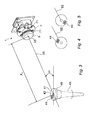
- an optical device 1 comprises a camera and a diaphragm 5 which is positioned and attached to the camera in order to be in the optical axis of the camera. Details of the camera are shown in fig. 2 .
- the diaphragm 5 is provided with a light passing aperture 53 and the diaphragm is positioned in order to have the centre point of this light passing aperture 53 coincide with the optical axis of the camera.
- the camera is connected to a support 20 which is adapted to fix the optical device at an appropriate position with an appropriate inclination with respect to a support. This support could be used to position the optical device, for instance, inside an apparatus, such as an apparatus for biological testing.
- the optical device 1 is also provided with a ring 7 positioned around the optical axis of the camera.
- the ring 7 comprises illumination sources 71 fixed thereon.
- the ring 7 may rotate around the optical axis of the camera over an angle of 360°.
- the ring 7 provides a support for positioning the illumination sources 71 around the optical axis of the camera.
- the illumination sources 71 are positioned around the optical axis to allow the illumination sources 71 to evenly, i.e. homogeneously, illuminate an object which is positioned within the increased depth of field of the camera and of which a picture is to be taken. As the object is located in the increased depth of field of the camera, the object is evenly illuminated.
- the even illumination provides a homogeneous quality of the image taken of the object with respect to the optical axis of the camera. The even illumination avoids creating an image with areas having both good quality and poor quality.
- the illumination sources may be symmetrically positioned on the ring 7. This means that both illumination sources 71 are separated by an angle of 180° between them.
- the illuminations sources 71 may each be separated by an angle of 120° between them.
- the relationship between the illumination sources 71 and the position of the object of which a photo is to be taken is more clearly indicated in fig. 3 .
- the illumination sources 71 may also have the form of illumination locations.
- An illumination location is a point of departure of light which is emitted from the illumination sources 71 in the direction of an object of which an image should be taken.
- An illumination location may, for instance, be the end of an optical fibre which is related to an illumination source 71.
- several illumination locations may relate to one illumination source 71. As the illumination locations are positioned around the optical axis of the camera, the effect is that the light emitted by the plurality of illumination locations allows an even illumination of the object.
- the at least one illumination source 71 may be associated with at least two illumination locations to provide an even illumination.
- the illumination locations may be symmetrically positioned around the optical axis to provide an even illumination for the object.
- the illumination locations may be evenly distributed around the optical axis to ensure even illumination of the object of which is image should be taken.
- the illumination source 71 may be associated with at least one illumination location.
- the optical device 1 comprises such illumination means.
- the optical device 1 comprises a support 20 for fixing the optical device 1 in an appropriate position and with an appropriate orientation with respect to an object of which an image should be taken.
- the optical device 1 further comprises a camera comprising a camera body 2, a lens holder 3, a lens housing 4 and a locking nut 6.
- the camera body 2 is fixed to a lens holder 3.
- the lens housing 4 is fixed to the lens holder 3 comprising in its interior at least one lens.
- the locking nut 6 is used for blocking the lens housing 4 in the lens holder 3.
- the optical device 1 also comprises a ring 7 provided with illuminating sources 71 comprising specific characteristics such as: a reduced size to comply with the size of the camera, a low power consumption to avoid increasing consumption cost, a variety of colours to provide different colour illumination effects, a reduced aperture to provide a focused beam to illuminate the object.
- the illumination sources may be in the form of LEDs.
- the LEDs are positioned evenly around the optical axis of the camera in order to allow the illumination sources to evenly illuminate an object within the increased depth of field of the camera as previously described.
- the optical axis and the specific functioning of those illuminating sources 71 will be described in detail with reference to fig. 3 .
- the ring 7 may rotate from one position to another position where the two positions are separated by an angle of 180° for example to provide an even illumination of the object.
- the illumination source 71 on the ring may provide two different illumination locations corresponding to the two positions of the ring 7.
- the ring 7 comprises six LEDs evenly spread out around the optical axis of the camera. It should be noted that another number of LEDs like four or eight can also be used as long as the LEDs cooperate to evenly illuminate an object within the increased depth of field of the camera.
- the diaphragm 5 is attached to the lens housing 4 and forms an opaque screen stopping the light from entering into the camera.
- the diaphragm 5 comprises a light passing aperture 53 so that of a beam of light the rays' incident on the diaphragm, only the ray which passes through the aperture 53 will contribute to the formation of an image in the camera, while those intercepted by the diaphragm 5 are excluded there from.
- the illumination source 71 is designed to optimize the density of light coming through the diaphragm 5 through the light aperture.
- the diaphragm 5 and the illumination source 71 provide an improved quality of an image to be taken in the increased depth of field of the camera.
- the diaphragm 5 is provided with screws 51 and 52, such as Allen screws, in order to fix the diaphragm 5 to the lens housing 4. It should be noted that the diaphragm 5 is positioned on the camera in order for the centre point of the aperture 53 of the diaphragm to coincide with the optical axis of the camera to which the diaphragm is attached. An adjuster comprising control knobs (not shown) can be provided on the diaphragm 5 to control the specific size of the diaphragm.
- the camera module used in the optical device 1 according to figs. 1 and 2 is typically based on a board with a photosensitive sensor, such as a complementary metal-oxide-semiconductor (CMOS) sensor.
- CMOS complementary metal-oxide-semiconductor
- the camera module is connected to an interface board based on a micro processor.
- the microprocessor manages the camera module and decodes the image obtained by the camera.
- the interface board has an embedded algorithm which is specific for the purpose of the optical device. For instance, if the optical device is used for reading a 2-D barcode, the embedded algorithm will be adapted to decode the 2-D barcode.
- the interface board may further manage the communication board which means that the interface board is linked to the operating system of the apparatus wherein the camera module is used. This communication could be used for test, calibration and debug purposes.
- the interface board may be provided with a memory system like flash, RAM and an EEPROM.
- the interface board may also provide a power supply with a voltage supervisor, interface connectors and some other simple circuits for signal adjusting.
- the image is acquired via the CMOS sensor and then transferred to the RAM memory for subsequent elaboration.
- the algorithm embedded in the interface board may then decode, for instance, the 2-D barcode and provides the results of this processing to the main board.
- the interface board based on a microprocessor may be responsible for managing the camera module in order to properly acquire the image to be processed.
- the diaphragm 5 is provided with a light passing aperture 53 that may regulate the amount of light that passes.
- the diaphragm 5 may be responsible for increasing the depth of field of the camera and so enlarge the range of object window where the images are on focus.
- the lens housing 4 may be blocked on the lens holder 3 by the lock nut 6 in order to fix the focus position of the lens.
- FIG. 3 A possible use of the optical device 1 according to the present invention is shown in fig. 3 .
- the optical device 1 is fixed in a certain position at a distance and inclination adapted to read a 2-D barcode 44 present on top of a tip 40 received in a recipient for the tip 45.
- the tip 40 has a circular top surface 41 with an aperture 42 in the centre thereof. This aperture 42 is needed for liquid handling via the bottom end of the tip 40. This allows the tip 40 to be used for transferring a certain amount of fluid from a first position for sucking in the fluid to a second position for dispensing the fluid at said second position.
- the tip 40 could be any tip used in a device for biological analyses. Alternatively, the tip could be of the type which is provided in its interior with a specific coating. In use, it is important to be able to identify the specific tip 40 which is positioned in the recipient 45. For this purpose the tip 40 carries a 2-D barcode 44. With this 2-D barcode 44, not only the type of tip 40 can be identified, but also the batch of which the tip is part. This information is important for checking whether the right tip is positioned at the right position, in order to identify whether the tip is present or not, in order to establish the batch number to which the tip belongs, etc.
- the total surface area available for printing the 2-D barcode 44 on top of the tip 40 is very limited because of the presence, on the one hand, of the border of the circular surface 41 of the tip and, on the other, of the presence of the aperture 42 in the centre of the top surface of the tip. Therefore, the 2-D barcode 44 may be relatively small with a dimension of typically 2 x 1 mm.
- the distance X 1 between the leading end of the optical device 1 and the centre of the tip 40 may be relatively long, in the order of 90-110mm.
- the fixed focus length of the camera comprising a predetermined depth of field used in the optical device 1 would not be able to produce images with sufficient quality of the barcode 44 in order to allow the decoding of the barcode 44.
- the problem relating to this lack of quality is that the tip 40 can rotate within the recipient 45. That means that even if the optical device 1 is fixed with respect to the recipient 45 for the tip, it is still possible that the position of the barcode 44 with respect to the optical device 1 can differ.
- Figs. 4 and 5 show a first and a second rotational position of the tip 40 with respect to the recipient 45 and therefore a first and second position of the barcode on top of the tip 40 with respect to the optical device 1.
- figs. 4 and 5 only part of the optical axis 55 is shown.
- the barcode 44 is positioned in a first position with respect to the optical device 1.
- the distance between the optical device 1 and the barcode 44 is longer than in the position according to fig. 4 .
- the camera of the optical device 1 needs to have a sufficient depth of field to allow the optical device 1 to take an image of the barcode 44 with sufficient quality for decoding the barcode.
- a first possibility is to position the object provided with the optical code 44 in a fixed position. Thereafter, the optical device 1 is placed in position wherein the optical device 1 can take an image of the optical code 44 on the object. This means that the optical device 1 is positioned to ensure that the optical code 44 is within the depth of field of the camera of the optical device 1.
- the optical device 1 is fixed in a position and thereafter the object provided with the optical code 44 is placed in a position with respect to the optical device 1, to have the optical code 44 within the increased depth of field of the camera of the optical device 1.
- the mutual position of the optical device 1 and the optical code 44 should be such that the code 44 is within the increased depth of field of the camera of the optical device 1.
- the predetermined depth of field of the optical device 1 is increased by using a diaphragm 5 with, in its centre, a light passing aperture 53.
- This light passing aperture 53 is circular and the centre point of the circular coincides with the optical axis 55 of the camera of the optical device 1.
- the shape of the aperture helps the optical device to have a similar resolution in all possible directions.
- rotation of the tip 40 has no effect on the quality of the image taken in, for instance, the position according to fig. 4 compared to the image taken in the position according to fig. 5 .
- the sufficient quality of the image of the barcode 44 in all possible positions can be guaranteed.
- the second adaptation related to the optical device 1 according to fig. 3 to ensure a good quality image is the presence of the ring 7 with the illumination means 71.
- the optical device 1 is specifically adapted to be used in the interior of an apparatus such as an apparatus for biological analyses. This means that the optical device 1 is used in the dark.
- the illumination means 71 are evenly positioned around the optical axis 55 to evenly illuminate the object of which an image must be taken, in this case the top surface 41 of the tip 40.
- the combination of the presence of a diaphragm 5 for increasing the depth of field and the illuminating sources 71 on the ring 7 provide together an equal image quality for the images obtained with the fixed focus camera in the optical device. This quality will be provided for all the possible positions of the barcode 44 with respect to the optical device 1.
- the optical device 1 is specifically suitable for reading a barcode on a consumable that is used in an apparatus for biological analyses and tests.
- This type of barcode may be present, for instance, on a consumable in the form of a tip.
- the optical device may be used to take an image of the surface of the tip in the area wherein the barcode is expected to be found. Once the image is taken, the image can be processed using image recognition techniques.
- a first use of the optical device 1 is to use the outcome of the image recognition as a means to check the barcode's presence or absence.
- the absence of the barcode could be an indication that the tip is not present or that the tip is not properly positioned in the apparatus.
- the optical device 1 can be used to read the barcode to thereby identify the specific tip that is positioned in the apparatus.
- the identification of the tip is an important safety step for the proper operation of the apparatus.
- the result of the identification of the consumable allows the operator or an automatic control system, in a first instance, to check whether the right consumable is positioned in the right place before the apparatus can authorise a specific analysis procedure or test to start.
- the identification of the consumable can also provide information about the specific batch of consumables from which the tip belongs to. It is possible that the results of a procedure or test need to be adjusted after the test is completed by applying a correction which is linked to the batch of consumables that is used in the procedure or test. Moreover or alternatively, the identification of the consumable could be used in a calibration procedure using information linked to a specific batch of consumables, prior to launching the apparatus or test.
- a second use of the optical device 1 is to use the identification of a first consumable used in an apparatus and to compare this first consumable with a further consumable which is used in the same apparatus.
- This second consumable could be identified in any proper way or manner, manually or automatically, for instance by using a further barcode reader.
- the identification of the first consumable including its type and the batch number, can be compared to similar information of the second consumable. Once the two consumables have been compared, it is possible, in the operation of the apparatus to only allow the start of a procedure or test if the identification of the first consumable confirms that it matches the identity of the second consumable.
- the algorithm used to process the image taken by the camera of the optical device has to be adapted to this specific use.
- the 2-D barcode in the example is a DataMatrix ECC-200 barcode. This type of barcode typically has a matrix of 8x18 elements.
- the position of the optical device 1 with respect to the top of the tip 40 used in this example is shown in fig. 3 .
- the dimensions of the different elements and the distances between the several elements are further detailed in figs. 6 and 8 .
- a photosensitive sensor 100 of the optical device 1 is positioned in a sensor plane 101.
- the sensor 100 is positioned in the optical axis 55 of the optical device.
- the target for taking an image is the 2-D barcode 44.
- the barcode 44 is positioned in a target plane 111.
- ⁇ is the angle between the optical axis 55 and the target plane 111 (see fig. 6 ) of the barcode 44.
- the angle ⁇ is set to be between 35° and 40°.
- a focus system is present in the form of a lens between the sensor 100 and the barcode 44.
- the lens 103 has an end lens plane 104.
- the distance between the sensor plane 101 and the end lens plane 104 is 25.25 mm.
- the lens 103 has a thickness taken in the direction of the optical axis of 14.45 mm.
- the distance between the end lens plane 104 and the target plane 111 is 102.45 mm.
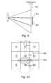
- depth of field is explained with reference to fig. 7 .
- the following definition is used to refer to the "depth of field” of the optical device: if an object is seen through an optical system, the depth of field is the interval of object-distances which give an acceptable sharpness of the image, for the particular use for which the image is taken.
- DOF U f - U n ;
- a schematical embodiment of an optical device is shown having two lenses, a first lens 201 and a second lens 202.
- the back focal length bfl 11.8mm
- the tolerance on the total distance is +/- 1.2mm, wherein the 'total distance' is the distance between the edge of the focus lens, lens 201 and the sensor 100.
- the dimension of the circle of confusion is calculated from the data matrix projected on the sensor 100.
- Fig. 9 represents a ray tracing from the lens along the optical axis 102.
- Fig. 10 represents a transverse view of the sensor array.
- the circle of confusion 300 has a radius of n-1 pixels.
- the area of confusion is indicated with reference number 301.
- the lens opening is controlled by a diaphragm 5, having a light passing aperture 53.
- the thickness of the diaphragm does not contribute to increase the lens opening but the amount of light getting into the optical system increases, the reflected rays as shown on in fig. 12 increase the amount of light.
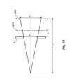
- the plane containing the barcode 44 is tilted with respect to the orthogonal plane as shown in fig. 13 .
- the minimum of DOF is now defined as the projection of the tip diameter along the optical axis 55. As it is interesting to compare the minimum of DOF to the actual DOF, this comparison is performed with the offset out of focus as defined on the fig. 13 .
- the condition on the lens opening is: d ⁇ 1.07 ⁇ mm
- the aperture 53 should at least have a diameter of 2 mm.
- the minimum depth of field is fixed at 15mm, this value being related to the usage of diaphragm of 2mm+/-0.05 mm of manufacturing tolerance and lens opening 2.18mm.
- the error on the focal distance is the characteristic that has the largest influence.
- V image distance
- the circle of confusion has basically a diameter of 0.032mm, 12% of uncertainty can make it decrease to 0.028mm.
- the Airy disk caused by diffraction has a diameter in the order of 0.0132mm which is small enough not to disturb the geometrical optics.
- the tuning is operated on the image distance (V) to get the expected DOF, previously obtained at the nominal position, in the first case 1) the DOF advances 1.2mm; in the second case 2) the DOF goes 1.2mm back.
- the error on the focal distance can be acceptably compensated by adjusting the position of the system.
Priority Applications (8)
| Application Number | Priority Date | Filing Date | Title |
|---|---|---|---|
| EP12305702.8A EP2677363A1 (de) | 2012-06-20 | 2012-06-20 | Optische Vorrichtung mit einer Kamera, einer Blende und Beleuchtungsmitteln |
| JP2015517759A JP6328620B2 (ja) | 2012-06-20 | 2013-06-20 | カメラと絞りとを含む光学デバイス |
| EP13729963.2A EP2864837B1 (de) | 2012-06-20 | 2013-06-20 | Optische vorrichtung mit einer kamera, einer blende und beleuchtungsmitteln |
| US14/402,619 US9936119B2 (en) | 2012-06-20 | 2013-06-20 | Optical device including a camera, a diaphragm and illumination means for increasing the predetermined depth of field of the camera |
| CN201320355993.5U CN203561816U (zh) | 2012-06-20 | 2013-06-20 | 光学设备及用于样品的自动分析的仪器 |
| PCT/EP2013/062868 WO2013190035A1 (en) | 2012-06-20 | 2013-06-20 | An optical device including a camera, a diaphragm and illumination means |
| CN201310245917.3A CN103513494B (zh) | 2012-06-20 | 2013-06-20 | 包括照相机和光圈的光学设备 |
| KR1020147036742A KR102015904B1 (ko) | 2012-06-20 | 2013-06-20 | 카메라, 조리개 및 조명 수단을 포함하는 광학 디바이스 |
Applications Claiming Priority (1)
| Application Number | Priority Date | Filing Date | Title |
|---|---|---|---|
| EP12305702.8A EP2677363A1 (de) | 2012-06-20 | 2012-06-20 | Optische Vorrichtung mit einer Kamera, einer Blende und Beleuchtungsmitteln |
Publications (1)
| Publication Number | Publication Date |
|---|---|
| EP2677363A1 true EP2677363A1 (de) | 2013-12-25 |
Family
ID=48656054
Family Applications (2)
| Application Number | Title | Priority Date | Filing Date |
|---|---|---|---|
| EP12305702.8A Withdrawn EP2677363A1 (de) | 2012-06-20 | 2012-06-20 | Optische Vorrichtung mit einer Kamera, einer Blende und Beleuchtungsmitteln |
| EP13729963.2A Active EP2864837B1 (de) | 2012-06-20 | 2013-06-20 | Optische vorrichtung mit einer kamera, einer blende und beleuchtungsmitteln |
Family Applications After (1)
| Application Number | Title | Priority Date | Filing Date |
|---|---|---|---|
| EP13729963.2A Active EP2864837B1 (de) | 2012-06-20 | 2013-06-20 | Optische vorrichtung mit einer kamera, einer blende und beleuchtungsmitteln |
Country Status (6)
| Country | Link |
|---|---|
| US (1) | US9936119B2 (de) |
| EP (2) | EP2677363A1 (de) |
| JP (1) | JP6328620B2 (de) |
| KR (1) | KR102015904B1 (de) |
| CN (2) | CN103513494B (de) |
| WO (1) | WO2013190035A1 (de) |
Families Citing this family (6)
| Publication number | Priority date | Publication date | Assignee | Title |
|---|---|---|---|---|
| EP2677363A1 (de) * | 2012-06-20 | 2013-12-25 | bioMérieux | Optische Vorrichtung mit einer Kamera, einer Blende und Beleuchtungsmitteln |
| CN105049556B (zh) * | 2015-06-30 | 2018-07-06 | 广东欧珀移动通信有限公司 | 移动终端 |
| JP7336094B2 (ja) * | 2019-02-08 | 2023-08-31 | タカノ株式会社 | 撮像装置 |
| EP3800877B1 (de) * | 2019-07-11 | 2022-08-10 | SZ DJI Technology Co., Ltd. | Schärfenziehradanordnung, handgehaltene vorrichtung und bilderfassungssystem |
| KR102473150B1 (ko) | 2020-08-20 | 2022-12-01 | 엘텍코리아 주식회사 | 사용자의 카메라 조명이 외부에 노출되지 않는 조명 비노출형 카메라 및 이를 이용한 카메라 조명 비노출 제어방법 |
| DE102021114556A1 (de) * | 2021-06-07 | 2022-12-08 | Sick Ag | Kamera und Verfahren zur Erfassung von durch einen Erfassungsbereich bewegten Objekten |
Citations (6)
| Publication number | Priority date | Publication date | Assignee | Title |
|---|---|---|---|---|
| WO1999006871A1 (de) * | 1997-07-30 | 1999-02-11 | Rodenstock Präzisionsoptik Gmbh | Kamera und insbesondere modulare dentalkamera |
| JP2000099625A (ja) * | 1998-09-28 | 2000-04-07 | Nidek Co Ltd | 文字認識装置 |
| JP2003098426A (ja) * | 2001-09-20 | 2003-04-03 | Olympus Optical Co Ltd | 撮影レンズ、その撮影レンズを用いたカメラ及びそのカメラにおける絞り |
| US20070119942A1 (en) | 2005-11-29 | 2007-05-31 | Datalogic S.P.A. | Method, diaphragms and optical receiving devices for improving the depth of field in a linear optical code reader |
| DE102009017819A1 (de) * | 2009-04-20 | 2010-10-21 | DüRR DENTAL AG | Dentale oder medizinische Kamera |
| US20110234781A1 (en) * | 2008-01-14 | 2011-09-29 | Kaltenbach & Voigt Gmbh | Dental Intra-oral Camera |
Family Cites Families (35)
| Publication number | Priority date | Publication date | Assignee | Title |
|---|---|---|---|---|
| US4459005A (en) * | 1983-04-13 | 1984-07-10 | Eastman Kodak Company | Flash exposure control apparatus for a fixed-focus camera |
| JPH08190600A (ja) * | 1995-01-11 | 1996-07-23 | Olympus Optical Co Ltd | 情報再生システム |
| KR960035759A (ko) * | 1995-03-03 | 1996-10-24 | 김광호 | 코히어런스 팩터 조절용 기구 및 그 조절방법 |
| US5585616A (en) * | 1995-05-05 | 1996-12-17 | Rockwell International Corporation | Camera for capturing and decoding machine-readable matrix symbol images applied to reflective surfaces |
| US6034372A (en) * | 1997-12-03 | 2000-03-07 | The United States Of America As Represented By The Secretary Of The Air Force | Pupil stop for multi-band focal plane arrays |
| US6512919B2 (en) * | 1998-12-14 | 2003-01-28 | Fujitsu Limited | Electronic shopping system utilizing a program downloadable wireless videophone |
| JP3554703B2 (ja) * | 2000-10-12 | 2004-08-18 | リバーベル株式会社 | 情報端末装置 |
| US6749310B2 (en) * | 2001-09-07 | 2004-06-15 | Contrast Lighting Services, Inc. | Wide area lighting effects system |
| US6870684B2 (en) * | 2001-09-24 | 2005-03-22 | Kulicke & Soffa Investments, Inc. | Multi-wavelength aperture and vision system and method using same |
| US6761561B2 (en) * | 2002-06-07 | 2004-07-13 | Schick Technologies | Wireless dental camera |
| EP1531629A4 (de) * | 2002-07-26 | 2006-05-17 | Olympus Corp | Bildverarbeitungssystem |
| JP2004110760A (ja) * | 2002-09-19 | 2004-04-08 | Aisin Engineering Kk | コード読取装置 |
| JP2004246172A (ja) * | 2003-02-14 | 2004-09-02 | Konica Minolta Holdings Inc | 撮像装置及び携帯端末 |
| CN101699850A (zh) * | 2004-01-23 | 2010-04-28 | 奥林巴斯株式会社 | 图像处理系统以及照相机 |
| JP2005292443A (ja) * | 2004-03-31 | 2005-10-20 | Nec Saitama Ltd | カメラの至近距離撮影用の制御装置 |
| EP1829479A1 (de) * | 2005-02-16 | 2007-09-05 | Matsushita Electric Industrial Co., Ltd. | Vorrichtung zur biometrischen unterscheidung, authentifizierungsvorrichtung und verfahren zur biometrischen unterscheidung |
| JP4389812B2 (ja) * | 2005-03-03 | 2009-12-24 | 株式会社デンソーウェーブ | 光学情報読取装置 |
| WO2006095110A2 (fr) * | 2005-03-07 | 2006-09-14 | Dxo Labs | Procédé pour commander une action, notamment une modification de netteté, à partir d'une image numérique en couleurs |
| KR101334081B1 (ko) * | 2005-07-08 | 2013-11-29 | 일렉트로 싸이언티픽 인더스트리이즈 인코포레이티드 | 광원의 평면 어레이에 의해 방출된 수렴 광선을 달성하는 방법 및 장치 |
| US7400458B2 (en) * | 2005-08-12 | 2008-07-15 | Philips Lumileds Lighting Company, Llc | Imaging optics with wavelength dependent aperture stop |
| US20070133983A1 (en) * | 2005-12-14 | 2007-06-14 | Matilda Traff | Light-controlling element for a camera |
| US20070139792A1 (en) * | 2005-12-21 | 2007-06-21 | Michel Sayag | Adjustable apodized lens aperture |
| US7585122B2 (en) | 2006-03-15 | 2009-09-08 | Nokia Corporation | Aperture construction for a mobile camera |
| US7711259B2 (en) * | 2006-07-14 | 2010-05-04 | Aptina Imaging Corporation | Method and apparatus for increasing depth of field for an imager |
| JP5315574B2 (ja) * | 2007-03-22 | 2013-10-16 | 富士フイルム株式会社 | 撮像装置 |
| EP2487483B1 (de) * | 2007-07-10 | 2018-10-03 | Datalogic IP TECH S.r.l. | Sichtsystem |
| US20100046792A1 (en) * | 2008-08-22 | 2010-02-25 | Pioneer Hi-Bred International, Inc. | Methods for counting corn silks or other plural elongated strands and use of the count for characterizing the strands or their origin |
| GB2463480A (en) * | 2008-09-12 | 2010-03-17 | Sharp Kk | Camera Having Large Depth of Field |
| WO2011038457A1 (en) * | 2009-09-30 | 2011-04-07 | Lions Eye Institute Limited | Imager, module for an imager, imaging system and method |
| JP5130332B2 (ja) * | 2009-12-11 | 2013-01-30 | 東芝テック株式会社 | スキャナ |
| KR20110009084U (ko) * | 2010-03-17 | 2011-09-23 | 재 영 이 | Dslr 카메라용 led 링 라이트 장치 |
| JP5330313B2 (ja) * | 2010-05-24 | 2013-10-30 | 株式会社日立ハイテクノロジーズ | 生体試料の分析装置 |
| KR101655742B1 (ko) * | 2010-07-16 | 2016-09-09 | 주식회사 듀얼어퍼처인터네셔널 | 다중 조리개 촬영용 플래시 시스템 |
| US8730383B2 (en) * | 2011-11-30 | 2014-05-20 | Cognex Corporation | System and method for controlling illumination in a vision system |
| EP2677363A1 (de) * | 2012-06-20 | 2013-12-25 | bioMérieux | Optische Vorrichtung mit einer Kamera, einer Blende und Beleuchtungsmitteln |
-
2012
- 2012-06-20 EP EP12305702.8A patent/EP2677363A1/de not_active Withdrawn
-
2013
- 2013-06-20 JP JP2015517759A patent/JP6328620B2/ja active Active
- 2013-06-20 CN CN201310245917.3A patent/CN103513494B/zh active Active
- 2013-06-20 EP EP13729963.2A patent/EP2864837B1/de active Active
- 2013-06-20 KR KR1020147036742A patent/KR102015904B1/ko active IP Right Grant
- 2013-06-20 WO PCT/EP2013/062868 patent/WO2013190035A1/en active Application Filing
- 2013-06-20 CN CN201320355993.5U patent/CN203561816U/zh not_active Expired - Lifetime
- 2013-06-20 US US14/402,619 patent/US9936119B2/en active Active
Patent Citations (6)
| Publication number | Priority date | Publication date | Assignee | Title |
|---|---|---|---|---|
| WO1999006871A1 (de) * | 1997-07-30 | 1999-02-11 | Rodenstock Präzisionsoptik Gmbh | Kamera und insbesondere modulare dentalkamera |
| JP2000099625A (ja) * | 1998-09-28 | 2000-04-07 | Nidek Co Ltd | 文字認識装置 |
| JP2003098426A (ja) * | 2001-09-20 | 2003-04-03 | Olympus Optical Co Ltd | 撮影レンズ、その撮影レンズを用いたカメラ及びそのカメラにおける絞り |
| US20070119942A1 (en) | 2005-11-29 | 2007-05-31 | Datalogic S.P.A. | Method, diaphragms and optical receiving devices for improving the depth of field in a linear optical code reader |
| US20110234781A1 (en) * | 2008-01-14 | 2011-09-29 | Kaltenbach & Voigt Gmbh | Dental Intra-oral Camera |
| DE102009017819A1 (de) * | 2009-04-20 | 2010-10-21 | DüRR DENTAL AG | Dentale oder medizinische Kamera |
Also Published As
| Publication number | Publication date |
|---|---|
| WO2013190035A1 (en) | 2013-12-27 |
| JP2015526948A (ja) | 2015-09-10 |
| KR20150021965A (ko) | 2015-03-03 |
| CN203561816U (zh) | 2014-04-23 |
| CN103513494B (zh) | 2018-01-02 |
| US20150156398A1 (en) | 2015-06-04 |
| EP2864837B1 (de) | 2023-08-02 |
| EP2864837A1 (de) | 2015-04-29 |
| US9936119B2 (en) | 2018-04-03 |
| JP6328620B2 (ja) | 2018-05-23 |
| CN103513494A (zh) | 2014-01-15 |
| KR102015904B1 (ko) | 2019-10-21 |
Similar Documents
| Publication | Publication Date | Title |
|---|---|---|
| EP2864837B1 (de) | Optische vorrichtung mit einer kamera, einer blende und beleuchtungsmitteln | |
| CN106959293B (zh) | 通过视觉系统检测反光面上缺陷的系统及方法 | |
| US8576390B1 (en) | System and method for determining and controlling focal distance in a vision system camera | |
| US20150269403A1 (en) | Barcode reader having multiple sets of imaging optics | |
| JP5328812B2 (ja) | 物体を検出するための補助照明のための装置及び方法 | |
| US7292331B2 (en) | Inspection lighting head system and method of operation | |
| US7715023B2 (en) | Jig mounting apparatus | |
| KR101578496B1 (ko) | 이미지 센서의 틸트 결정 방법 | |
| US11493454B2 (en) | System and method for detecting defects on a specular surface with a vision system | |
| CN111929038B (zh) | 微镜片的测试装置、方法、测试设备及计算机存储介质 | |
| EP1035408A1 (de) | Vorrichtung zur messung der eigenschaften eines optischen winkels | |
| CN106483734B (zh) | 照明组件 | |
| KR20150118073A (ko) | 카메라 렌즈에 의한 비네팅을 측정하는 시스템 | |
| RU178286U1 (ru) | Автоматизированное оптико-электронное устройство для диагностики защитных голограмм | |
| US9027836B1 (en) | Barcode reader configured for multi-lens ranging | |
| KR101739696B1 (ko) | 재질인식 조명 시스템 및 이를 이용한 재질인식 방법 | |
| JP6039119B1 (ja) | 欠陥検査装置 | |
| US20100295939A1 (en) | Table gauge | |
| KR101447857B1 (ko) | 렌즈 모듈 이물 검사 시스템 | |
| JP2020134174A (ja) | 検査装置 | |
| JP2003202302A (ja) | 表面欠陥検査装置 | |
| JP4056399B2 (ja) | 外観欠陥検査装置 | |
| JP2023160096A (ja) | 表面欠陥検出装置および表面欠陥検出方法 | |
| JPH085577A (ja) | カメラ受光位置補正用標板およびカメラ位置補正装置ならびに外観欠陥検査装置 | |
| CN115436018A (zh) | 光学检测系统 |
Legal Events
| Date | Code | Title | Description |
|---|---|---|---|
| PUAI | Public reference made under article 153(3) epc to a published international application that has entered the european phase |
Free format text: ORIGINAL CODE: 0009012 |
|
| AK | Designated contracting states |
Kind code of ref document: A1 Designated state(s): AL AT BE BG CH CY CZ DE DK EE ES FI FR GB GR HR HU IE IS IT LI LT LU LV MC MK MT NL NO PL PT RO RS SE SI SK SM TR |
|
| AX | Request for extension of the european patent |
Extension state: BA ME |
|
| STAA | Information on the status of an ep patent application or granted ep patent |
Free format text: STATUS: THE APPLICATION IS DEEMED TO BE WITHDRAWN |
|
| 18D | Application deemed to be withdrawn |
Effective date: 20140626 |