EP1511570B1 - Mikrofluidstrukturen - Google Patents
Mikrofluidstrukturen Download PDFInfo
- Publication number
- EP1511570B1 EP1511570B1 EP03757231A EP03757231A EP1511570B1 EP 1511570 B1 EP1511570 B1 EP 1511570B1 EP 03757231 A EP03757231 A EP 03757231A EP 03757231 A EP03757231 A EP 03757231A EP 1511570 B1 EP1511570 B1 EP 1511570B1
- Authority
- EP
- European Patent Office
- Prior art keywords
- micro
- fluidic system
- micro fluidic
- posts
- flow
- Prior art date
- Legal status (The legal status is an assumption and is not a legal conclusion. Google has not performed a legal analysis and makes no representation as to the accuracy of the status listed.)
- Expired - Lifetime
Links
Images


Classifications
-
- B—PERFORMING OPERATIONS; TRANSPORTING
- B01—PHYSICAL OR CHEMICAL PROCESSES OR APPARATUS IN GENERAL
- B01L—CHEMICAL OR PHYSICAL LABORATORY APPARATUS FOR GENERAL USE
- B01L3/00—Containers or dishes for laboratory use, e.g. laboratory glassware; Droppers
- B01L3/50—Containers for the purpose of retaining a material to be analysed, e.g. test tubes
- B01L3/502—Containers for the purpose of retaining a material to be analysed, e.g. test tubes with fluid transport, e.g. in multi-compartment structures
- B01L3/5027—Containers for the purpose of retaining a material to be analysed, e.g. test tubes with fluid transport, e.g. in multi-compartment structures by integrated microfluidic structures, i.e. dimensions of channels and chambers are such that surface tension forces are important, e.g. lab-on-a-chip
- B01L3/50273—Containers for the purpose of retaining a material to be analysed, e.g. test tubes with fluid transport, e.g. in multi-compartment structures by integrated microfluidic structures, i.e. dimensions of channels and chambers are such that surface tension forces are important, e.g. lab-on-a-chip characterised by the means or forces applied to move the fluids
-
- B—PERFORMING OPERATIONS; TRANSPORTING
- B01—PHYSICAL OR CHEMICAL PROCESSES OR APPARATUS IN GENERAL
- B01L—CHEMICAL OR PHYSICAL LABORATORY APPARATUS FOR GENERAL USE
- B01L3/00—Containers or dishes for laboratory use, e.g. laboratory glassware; Droppers
- B01L3/50—Containers for the purpose of retaining a material to be analysed, e.g. test tubes
- B01L3/502—Containers for the purpose of retaining a material to be analysed, e.g. test tubes with fluid transport, e.g. in multi-compartment structures
- B01L3/5027—Containers for the purpose of retaining a material to be analysed, e.g. test tubes with fluid transport, e.g. in multi-compartment structures by integrated microfluidic structures, i.e. dimensions of channels and chambers are such that surface tension forces are important, e.g. lab-on-a-chip
- B01L3/502746—Containers for the purpose of retaining a material to be analysed, e.g. test tubes with fluid transport, e.g. in multi-compartment structures by integrated microfluidic structures, i.e. dimensions of channels and chambers are such that surface tension forces are important, e.g. lab-on-a-chip characterised by the means for controlling flow resistance, e.g. flow controllers, baffles or throttle valves
-
- B—PERFORMING OPERATIONS; TRANSPORTING
- B01—PHYSICAL OR CHEMICAL PROCESSES OR APPARATUS IN GENERAL
- B01L—CHEMICAL OR PHYSICAL LABORATORY APPARATUS FOR GENERAL USE
- B01L3/00—Containers or dishes for laboratory use, e.g. laboratory glassware; Droppers
- B01L3/50—Containers for the purpose of retaining a material to be analysed, e.g. test tubes
- B01L3/502—Containers for the purpose of retaining a material to be analysed, e.g. test tubes with fluid transport, e.g. in multi-compartment structures
- B01L3/5027—Containers for the purpose of retaining a material to be analysed, e.g. test tubes with fluid transport, e.g. in multi-compartment structures by integrated microfluidic structures, i.e. dimensions of channels and chambers are such that surface tension forces are important, e.g. lab-on-a-chip
- B01L3/502761—Containers for the purpose of retaining a material to be analysed, e.g. test tubes with fluid transport, e.g. in multi-compartment structures by integrated microfluidic structures, i.e. dimensions of channels and chambers are such that surface tension forces are important, e.g. lab-on-a-chip specially adapted for handling suspended solids or molecules independently from the bulk fluid flow, e.g. for trapping or sorting beads or physically stretching molecules
-
- G—PHYSICS
- G01—MEASURING; TESTING
- G01N—INVESTIGATING OR ANALYSING MATERIALS BY DETERMINING THEIR CHEMICAL OR PHYSICAL PROPERTIES
- G01N30/00—Investigating or analysing materials by separation into components using adsorption, absorption or similar phenomena or using ion-exchange, e.g. chromatography or field flow fractionation
- G01N30/02—Column chromatography
- G01N30/60—Construction of the column
- G01N30/6052—Construction of the column body
- G01N30/6065—Construction of the column body with varying cross section
-
- G—PHYSICS
- G01—MEASURING; TESTING
- G01N—INVESTIGATING OR ANALYSING MATERIALS BY DETERMINING THEIR CHEMICAL OR PHYSICAL PROPERTIES
- G01N30/00—Investigating or analysing materials by separation into components using adsorption, absorption or similar phenomena or using ion-exchange, e.g. chromatography or field flow fractionation
- G01N30/02—Column chromatography
- G01N30/60—Construction of the column
- G01N30/6095—Micromachined or nanomachined, e.g. micro- or nanosize
-
- B—PERFORMING OPERATIONS; TRANSPORTING
- B01—PHYSICAL OR CHEMICAL PROCESSES OR APPARATUS IN GENERAL
- B01L—CHEMICAL OR PHYSICAL LABORATORY APPARATUS FOR GENERAL USE
- B01L2200/00—Solutions for specific problems relating to chemical or physical laboratory apparatus
- B01L2200/06—Fluid handling related problems
- B01L2200/0647—Handling flowable solids, e.g. microscopic beads, cells, particles
- B01L2200/0668—Trapping microscopic beads
-
- B—PERFORMING OPERATIONS; TRANSPORTING
- B01—PHYSICAL OR CHEMICAL PROCESSES OR APPARATUS IN GENERAL
- B01L—CHEMICAL OR PHYSICAL LABORATORY APPARATUS FOR GENERAL USE
- B01L2300/00—Additional constructional details
- B01L2300/18—Means for temperature control
-
- B—PERFORMING OPERATIONS; TRANSPORTING
- B01—PHYSICAL OR CHEMICAL PROCESSES OR APPARATUS IN GENERAL
- B01L—CHEMICAL OR PHYSICAL LABORATORY APPARATUS FOR GENERAL USE
- B01L2400/00—Moving or stopping fluids
- B01L2400/04—Moving fluids with specific forces or mechanical means
- B01L2400/0403—Moving fluids with specific forces or mechanical means specific forces
- B01L2400/0406—Moving fluids with specific forces or mechanical means specific forces capillary forces
-
- B—PERFORMING OPERATIONS; TRANSPORTING
- B01—PHYSICAL OR CHEMICAL PROCESSES OR APPARATUS IN GENERAL
- B01L—CHEMICAL OR PHYSICAL LABORATORY APPARATUS FOR GENERAL USE
- B01L2400/00—Moving or stopping fluids
- B01L2400/08—Regulating or influencing the flow resistance
- B01L2400/084—Passive control of flow resistance
- B01L2400/086—Passive control of flow resistance using baffles or other fixed flow obstructions
-
- G—PHYSICS
- G01—MEASURING; TESTING
- G01N—INVESTIGATING OR ANALYSING MATERIALS BY DETERMINING THEIR CHEMICAL OR PHYSICAL PROPERTIES
- G01N30/00—Investigating or analysing materials by separation into components using adsorption, absorption or similar phenomena or using ion-exchange, e.g. chromatography or field flow fractionation
- G01N30/02—Column chromatography
- G01N30/50—Conditioning of the sorbent material or stationary liquid
- G01N30/52—Physical parameters
- G01N2030/524—Physical parameters structural properties
- G01N2030/525—Physical parameters structural properties surface properties, e.g. porosity
-
- Y—GENERAL TAGGING OF NEW TECHNOLOGICAL DEVELOPMENTS; GENERAL TAGGING OF CROSS-SECTIONAL TECHNOLOGIES SPANNING OVER SEVERAL SECTIONS OF THE IPC; TECHNICAL SUBJECTS COVERED BY FORMER USPC CROSS-REFERENCE ART COLLECTIONS [XRACs] AND DIGESTS
- Y10—TECHNICAL SUBJECTS COVERED BY FORMER USPC
- Y10T—TECHNICAL SUBJECTS COVERED BY FORMER US CLASSIFICATION
- Y10T436/00—Chemistry: analytical and immunological testing
- Y10T436/25—Chemistry: analytical and immunological testing including sample preparation
Definitions
- the present invention relates to micro fluidic structures, and in particular to a micro structure defining a liquid flow system, wherein capillary action is utilized as the main driving force for liquid transport through said structure.
- micro fluidic structure according to the invention is useful in various fields of application such as miniaturized bioassays, preparatory steps for such assays, separation, electrophoresis, capillary chromatography, micro reaction cavity procedures, miniaturized liquid communication units, biosensor flow cells and the like.
- Liquid transport through channels or structures on a micro scale has important implications in a number of different technologies.
- Controlled transport of fluids through micro channels has been a challenge, with the microstructure itself imparting difficulties not found on a larger scale.
- the driving force utilized in most micro channel structures depends on electro-endosmosis, gravitational forces, external pressure or capillary migration.
- Surface materials often have unbound electrons, polar moieties, or other features generating a surface charge or reactivity. Surface characteristics often have a more pronounced impact on a micro scale system than on a larger structure. This is particularly true in micro systems where the fluid flow is driven by attractions between liquids and the surface materials through which they are transported.
- ⁇ gl represents the surface tension of the fluid with respect to the air (millijoules/m 2 ), g is the gravitational constant (m/s 2 ), r is the radius of the capillary tube (m), and ⁇ is the fluid density (kg/n 3 ).
- Planar micro structures have been developed in which a number of grooves or channels are made, typically such a planar structure is produced by etching grooves in a semiconductor substrate, such as a silicon wafer, and then covering the etched surface by a cover plate to complete the channels. Such structures are, however, rather time consuming and expensive to produce.
- micro structures need to be customized, e.g. by the addition of chemical reagents, the functionalization of surfaces etc., these steps often need to be performed by somebody other than the producer of the micro structure.
- the micro structures are manufactured at one location and shipped to another facility e.g. for the addition of reagents, whereupon they often need to be returned to the manufacturer for closing and sealing.
- One aim of the present invention is therefore to make available a micro structure offering greater flexibility and ease, in particular with regard to the post-production customization.
- Systems used at present utilize external means, e.g. gravity, centrifugal force (spinning of disk elements with micro channels on the surface), or pressure to impose transport of liquids in channels.
- electric fields can be used to impose transport of dissolved charged species in micro systems.
- external auxiliary equipment is employed, such as a motor to generate the spinning of a disk, pumps to create pressure, electrodes and power supplies to apply electric fields etc.
- Such equipment is costly and sometimes rather complex.
- Another aim of the invention is therefore to make available a micro structure with built-in functionality, removing or reducing the need of external means to impose liquid transport.
- EP 1 120 164 describes the use of a plurality of micro structures in a capillary pathway, said pathway having at least one curved portion, the pathway comprising a base, an inner wall defined by a first radius from a center point and defined by a second radius greater than the first radius, the inner wall and outer wall being fixed to the base and defining the lateral boundaries of the capillary pathway, and a lid extending at least from the inner wall to the outer wall covering the capillary pathway. It becomes clear that the micro structures themselves do not form a capillary pathway, but only influence the flow as the fluid travels around curved portions in said capillary pathway, the flow being somewhat slower near the inner wall of a curved portion than near the outer wall.
- U.S. 5,885,527 cited in the above EP 1 120 164 describes assay devices including micro structures forming reaction barriers. These reaction barriers are formed by corrugated or otherwise patterned surfaces, having grooves which together with a cover or top member form narrow channels between different chambers in said device. It is clear from the description and figures, that the capillary channels are indeed formed only when a top member is placed on a bottom member a capillary distance apart. Further, the top and bottom members may be married, the various chambers sealed and the capillaries formed by a number of techniques, including but not limited to, gluing, welding by ultrasound, riveting and the like.
- U.S. 5,837,115 discloses a sorting apparatus and method for fractionating and simultaneously viewing individual micro structures, such as cells, viruses, macro molecules or minute particles in a fluid medium.
- the aim of the invention is to replace agarose gels and other traditionally used fractionation media with a lattice structure with uniform distribution, size and shape of the hindered environment.
- the hindered environment may be formed by posts, bunkers, v-shaped or cup-shaped structures, forming sifting means for the cells, viruses etc under study.
- This structure is covered by ceiling means positioned over the lattice causing the migration of microstructures in essentially a single layer through the sifting means exclusively.
- the invention according to U.S. 5,837,115 does not seem to consider capillary forces, but instead suggests the provision of electrodes for generating an electric field over the lattice structure.
- micro fluidic structures integrated in a support which is suitable for mass production, and in a configuration which makes the micro fluidic device, comprising said structures, easily handled in the down-stream production process, and in particular in the customization of the device.
- One aim of the present invention is therefore to provide a micro-fluidic structure, i.e. a geometric micro structure defining a liquid flow system, suitable for capillary transport of liquids and which is inexpensive to produce, optionally permitting a disposable type product, optionally having branched flow channels, optionally exhibiting local surface characteristics, and providing great freedom in choice of material, e.g. with regard to surface, optical and electric properties.
- a micro-fluidic structure i.e. a geometric micro structure defining a liquid flow system, suitable for capillary transport of liquids and which is inexpensive to produce, optionally permitting a disposable type product, optionally having branched flow channels, optionally exhibiting local surface characteristics, and providing great freedom in choice of material, e.g. with regard to surface, optical and electric properties.
- the micro fluidic structure according to the present invention comprises various forms of geometric micro structures defining the desired liquid flow system.
- the present invention in its broadest aspect provides a flow path consisting of a multitude of micro structures inducing the flow of fluids through said flow path, as well as methods where this flow path is used.
- the invention in particular provides a micro fluidic system comprising a substrate, and, provided on said substrate, at least one flow path and functional means in which liquid samples can be treated by desired procedures, wherein said at least one flow path is/are laid out to form a pattern for the transport of liquid samples to, through and from said functional means; wherein the flow path consists of a plurality of micro posts protruding upwards from said substrate; wherein the spacing between the micro posts is such as to induce a capillary action in a liquid sample applied anywhere to said flow path, so as to force said liquid to move from where said liquid sample was applied.
- micro as in micro fluidic, micro structure etc is used to define a device or a process which comprises or involves at least one feature having a leght, width or height normally expressed in micrometers ( ⁇ m, 1 x 10 -6 m).
- nano is here used in its generally accepted meaning, as in nanometer (nm, 1 x 10 -9 m).
- passive as used in e.g. "passive control” or “passive fluid dynamics” refers for the purposes of this invention to a control that is not influenced by actions taken during a process that is to be carried out, but rather the control is determined by fixed system parameters, which are design dependent.
- the passive control is generated by using the natural capillary forces that exist on a micro scale.
- open in this context means that the flow paths defined by the micro structures are accessible from above and have no cover or lid which takes part in creating the capillary flow.
- the above definition does however not rule out that a secondary cover or lid, at a distance from the micro structure, can be provided.
- hydrophilic groups refers to substrates and substances having polar and/or charged groups, such as hydroxyl, carboxyl, amino, sulphonate, thiol, aldehyde etc.
- hydrophobic structure refers to substrates and substances having non polar structures.
- chemically reactive groups refers to all organic and inorganic groups used in covalent coupling of molecules to solid faces and known to persons skilled in the art, such a hydroxyl, carboxyl, amino, sulphonate, thiol, aldehyde etc.
- biological affinity refers to substances having specific binding of a substance or a defined group of related substances.
- exemplary substances are antibodies, antigens, haptens, biotin, avidin, lectin, sugar, nucleic acids, hormones and their receptors.
- the invention in its broadest aspect provides a multi-element capillary structure adapted to effect the capillary flow of liquids along said structure in open systems by using micro-structures provided on or in said structure. Advantage is taken of the surface effects between a fluid and the surfaces contacting the fluid. These surface effects come into play at the micro scale.
- devices having a structure comprising at least one liquid flow path, connecting different processing compartments within said structure for carrying out a number of different unit operations.
- processing compartments, elements and/or devices are chemical reaction compartments, incubation compartments, wash compartments or elements, flow control elements, measurement elements, time gates, separation means, heating means, means for irradiation with electromagnetic radiation, magnetic means for trapping magnetic components of said liquid within said functional means, electrodes for applying voltage to the liquid over a selected region, detectors for detecting physical or chemical properties e.g, temperature, pH, viscosity, absorbance etc., or any other device or means for chemically, biologically or physically treating a liquid sample or reaction mixture located within or passing through said compartment, element and/or device.
- One physical parameter that characterizes the magnitude of the capillary force is the contact angle between the water and the surrounding material.
- the material e.g., glass
- hydrophilic When the material has a contact angle greater than 90° it is considered hydrophobic.
- pressure In the hydrophobic case, pressure is required to force water into the space.
- the narrower the capillary the greater the force that is required.
- the flow rates of the water depend more on pressure gradients and friction and less on whether the material is hydrophobic or hydrophilic.
- the contact area between liquid and the surface of the solid material is maximized, whereby the capillary force increases so that a fluid flow within or along the flow path according to the invention is spontaneously induced and maintained over a desired period of time.
- passive fluid dynamics This process represents what can be referred to as "passive fluid dynamics".
- the present inventors have found that it is advantageous to use such passive fluid dynamics to control and drive the flow of fluid in open micro channels or structures on a surface.
- the passive nature of the transport mechanism according to the invention makes it direction independent, as compared to a system on a spinning disk where mainly a radial transport is possible.
- Transport by application of an electric field is mainly bi-directional at best. Capillary flow can be induced in any direction, provided the pattern of micro structures forming the flow paths is designed properly.
- a person skilled in the field of desingning micro structures and fluid flow cannerls on such structures will be able to apply the teaching of the invention without undue experimentation.
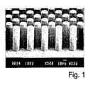
- Figure 1 shows a SEM microphotograph of an example of a micro fluidic structure embodying the inventive concept. It is evident from the picture that the micro posts have an identical shaped, a regular form and are evenly spaced over the support structure. Also the surface between the micro posts is even. A skilled person will recognize that the micro posts shown in the SEM microphotograph have a high aspect ratio. In this example, the micro posts were about 100 ⁇ m high, had a diameter of 20 ⁇ m and a center-to-center distance of 30 ⁇ m. This accounts for an aspect ratio of 1:5. It is generally held that an aspect ration > 1:2 is a high aspect ratio.
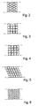
- Figures 2 through 6 show a number of different cross sections of the micro structures forming the fluid flow path according to the present invention.
- the micro structures or micro posts can have a cross section which is one of circular, elliptical, rhombic, triangular, square, rectangular, heptagonal, hexagonal etc or a combination thereof.
- the cross section can also be any fraction of the above forms, such as a half-circle, a crescent, U-shaped, X-shaped etc as long as the dimension and center-to-center distance of the individual microstructures is such, that capillary flow is induced without the provision of any lid or cover, limiting the flow path.
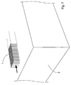
- Figure 7 shows schematically a flow path consisting of a multitude of circular micro posts 1 on a surface 2.
- the micro posts can naturally have any cross section, height and ceter-to-center distance, as long as the parameters are chosen such that capillary flow is induced.
- the direction of the capillary flow is indicated by the black arrow.
- the support 2 is schematically indicated as having a thickness comparable to the height of the micro posts. While this is not ruled out, the most frequently encountered supports will be considerably thicker.
- Figure 7 is thus only a schematic illustration.
- a device according to the invention may comprise a support and at least one flow path consisting of micro structures as shown in Figure 7 .
- a multitude of flow paths forming a channel system is required.
- the individual channels connect different functional regions, means or devices, such as reaction chambers, separation media etc.
- the basic structure embodying the inventive concept is a substrate having at least one flow path provided in or on its surface.
- This flow path or channel is formed by column like micro structures or micro posts, protruding from the surface of said surface.
- the characteristic feature of the flow path and the micro posts therein is that the dimensions of said posts and the distance between said posts are selected such that capillary flow of liquids can be maintained therein.
- the distance between said columns is in the range of 0.1 -1000 ⁇ m, preferably 1-100 ⁇ m.
- the columns are preferably higher than 1 ⁇ m, more preferably higher than 10 ⁇ m.
- Most preferably said micro posts have a high aspect ratio, that is a width to height ratio greater than 1:2.
- the micro posts can be either positioned within a secondary structure on the surface, such as a groove or a depressed area, or directly on the surface, protruding there from.
- a secondary structure such as a groove in a substrate
- the flow path will have a bottom located beneath the general substrate surface, and more or less vertical side walls, together with the bottom forming a channel. The capillary action inducing, the flow is however caused by the interaction between the liquid and the micro posts.
- the micro posts or columns are laid out as regions, preferably elongated, of upstanding columns, without any delimiting side walls.
- the flow path is subdivided into zones wherein the columns can have different column height, diameter, geometry and/or different column density, i.e. number of micro-posts per unit area.
- Figure 8 is a schematical illustration of this embodiment.
- a plurality of micro posts 1 are provided in close proximity in adjacent groups of micro posts having different size, shape or functionality.
- these groups are indicated 3, 4, and 5 and the differences shown as different size, shape and spacing only for the sake of illustration.
- Such groups can form an array, having desired functionality.
- Preferably said groups form a gradient, which can be continuous or discontinuous, preferably continuous.
- a first more dense zone 3 is provided, where the micro structures have a smaller diameter and smaller distance.
- Such zone can act as a sieve or "fence" preventing larger particles, e.g. cells from passing.
- a zone 4 with posts having relatively large spacing between them This can serve to temporarily decrease the time for a liquid-solid face interaction in a desired region, e.g. if it is desired that the sample be exposed to some surface bound moiety for an specified time, in order for a particular reaction to proceed to a reasonable completion etc.
- a zone 5 of larger micro posts squares in the shown example
- a second zone 4 similar to that is provided.
- the capillary flow path or paths has/have integrated surfaces or zones composed of bibulous material capable of capillary transport. This is schematically illustrated in Fig. 9 which shows a simple application of this concept.
- a closed channel structure not covered by the scope of the claims comprising a plurality of micro-posts 1 filling the channel.
- the structure has a bottom substrate 2 and a cover 6, the substrate also forming side walls (not shown), and having an input aperture or hole 7, an optional further aperture or hole 8, and an exit aperture (not shown). If a drop 9 of liquid is applied to the input aperture 7, a capillary flow will immediately begin, and will continue to draw liquid from the drop until the flow reaches the exit, where no further capillary action will occur. However, if a bibulous material such as pad 10 of filter paper or the like of sufficient size, is applied at, within or in contact with the exit aperture, this material will by its capability of drawing liquid act as a "flow sink", i.e. it will absorb the liquid that exits from the channel, thereby enabling an essentially continuous flow through the channel.
- a bibulous material such as pad 10 of filter paper or the like of sufficient size
- Another embodiment having a flow sink is that of the closed channel ending in an open region or zone of micro posts, said region having a relatively large area as compared to the channel.
- This large region will act as a flow sink in the same sense as the bibulous material discussed above. If e.g. heating means is provided to heat this region, evaporation of the liquid can be induced, thereby creating a sink that in principle could be maintained indefinitely. Evaporation of the liquid will also make possible the capture of components present in the flow, at a desired location and at a desired time in the device or process employing such device.
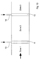
- Figure 10 shows schematically another embodiment and application of the flow path structures according to the invention, the flow path comprising a plurality of consecutive micro fluidic structures, interrupted by zones without such structures, i.e. a small space or discontinuity 11 and 12, said discontinuity acting as capillary barriers, preventing liquid from being transported across the zones without assistance.
- the direction of the liquid flow is illustrated with the large horizontal arrow.
- the discontinuities can be bridged or assisted transport can be brought about e.g. by applying a pressure pulse, whereby the capillary barriers provided by the voids are broken.
- the means for creating the pulse can be implemented by providing a very small channel 13 and 14 opening into the spacing, and for example momentarily applying sub-pressure (indicated with vertical arrows) in said channels. At the other end of the channel some means for providing a slight sub-pressure can be provided, whereby liquid from the regions on each side of the discontinuity will be forced into it, and when the gap is filled, capillary flow will again be resumed.
- Figure 11 shows a schematic partial view of a device according to the invention, where micro posts 1 are provided on a substrate 2, said substrate having larger protrusions 16 for carrying a cover or lid 15, said protrusions defining a distance between the surface the substrate and the lid considerably larger that the height of the micro posts, and such that no capillary interaction between the substrate and the lid can arise.
- the cover or lid 15 may further have apertures or holes 17, said holes preferably indication points for adding a sample or a reagent, for reading a result or for following the advancement of the reaction/reactions taking place on the substrate.
- the cover or lid is attached to the protrusions 16 only after the surface of the substrate has been functionalized or customized, i.e. after the addition of the necessary reagents and/or functionalities.
- Figure 12 shows schematically an exploded view of the embodiment of Figure 11 , where a pipette tip 18 is shown deposition of a drop of a liquid through an opening 17 on a flow path according to the invention.
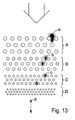
- Figure 13 illustrates an embodiment where groups of micro structures within a continuous flow path form a gradient with respect to at least one property, e.g. the shape, size, center-to-center distance or a functional / chemical property.
- the flow path comprises a discontinuos gradient with respect to the size and center-to-center distance of the micro structures, represented by the groups A, B, C and D.
- a gradient like this can function to delay the passage of biological or chemical entities, such as particles, cells, organelles, macro molecules or the like, in a desired manner, or separate such entities.
- Entities captured in zone A are illustrated by the shape "a", entities captured in zone B with "b” and so on.
- the shape "e” illustrates entities that pass unhindered through the gradient.
- the flow paths can comprise integrated surfaces or zones containing a number of different functional elements or devices for performing a number of different operations on the media located within or in association to the flow paths.
- functional elements or devices are electrodes and/or other means of electrical manipulation of liquids and reagents.
- the electrical manipulation can e.g. comprises oxidation/reduction of species.
- Other representative examples of functional devices are optics and other means to manipulate light e.g. for the purpose of measuring concentrations by absorbance, inducing conformational changes by light irradiation.
- Magnets or means for detection of magnetic substances can also be arranged in or around the flow paths. Thereby, magnetic particles can be trapped and retained at desired locations in the structure, and the magnetic property of the particles can thereby be used as a marker or indicator of successful transport to a certain point in the system. Furthermore, magnetic particles can be coated with substances with biological affinity and used in different kinds of assays.
- means for the manipulating of temperature can be provided in selected locations in a flow path according to the invention.
- means for the manipulating of temperature can be provided in selected locations in a flow path according to the invention.
- the particles within or in association to the flow paths, at least in one of the zones containing micro structures such as micro posts or columns, where there is subdivision between zones with and without these structures.
- the particles can thereby be bound by physical forces to said substrate, or chemically bound, e.g. covalently bound to said substrate.
- said particles can be mechanically trapped within the zone (zones) containing said structures.
- the substrate has reactive substances attached to its surface.
- reactive substances are used in connection with detection of substances of chemical or biological origin.
- the reactive substances are used in connection with immobilisation of substances of biological as well as non-biological origin, i.e. they are provided as sites to which the substances to be immobilized can react so as to become bound to the substrate.
- a reactive substance provided on the substrate is the use thereof in connection with separation of substances of biological as well as non-biological origin, where the substance can be selectively reactive with a species that one wishes to separate from another in a mixture.
- the surfaces of a channel in a structure according to the invention can be modified by chemical or physical means. Such a modified surface can thereby be used in connection with detection of substances of biological and chemical origin.
- a modified surface of this kind can be used in connection with immobilisation of substances of biological as well as non-biological origin. It can also be used in connection with separation of substances of biological as well as non-biological origin.
- flow paths are used as means for multi spot detection, whereby said paths optionally have particles provided therein, said particles having chemically reactive groups or substances with bio-affinity bound in the micro spot area.
- flow path structures are suitable applications of flow path structures according to the invention.
- a biological sample e.g. in blood, serum, plasma, urine, cerebral spinal fluid, tears, amniotic fluid, semen or saliva, the measurements preferably being based on specific biological interactions.
- a specific application is that said analyte is measured by immunological means.
- the analyte can also be detected by specific interactions using poly or oligonucleotides, preferably single stranded nucleic acids or aptameres.
- the flow path structures according to the invention can also be used for the separation of cells, and for the screening of synthetic or biological libraries.
- a channel for the purposes of the present invention goes beyond the ordinary concept of a channel, by allowing entirely open structures having no physical delimitations except for a bottom substrate on which the micro post or column structures are provided.
- the channel or flow path comprises a groove (i.e. having a bottom and side walls), there is the option to leave the channel open upwards.
- micro-fluidic structure may be very sensitive to oxygen, and therefore it may be absolutely necessary to exclude the sample liquid from atmospheric exposure.
- access openings in said cover for enabling introduction of e.g. reagents, gas, liquids, or samples into said structure.
- Such access openings can also be used for connecting external equipment, e.g. via suitable tubing or the like.
- Manufacturing of such microstructures could in its simplest form be done by direct curing of a photosensitive mono- or pre-polymer deposited on a substrate, employing a mask through which light is irradiated to initiate curing, and thereafter rinsing away the un-cured areas (thick film photo-resist process).
- An other straightforward method is through replication of an original into a polymer.
- the original could be manufactured in silicon through a DRIE-process (Deap Reactive Ion Etch) where high aspect ration structures could be produced.
- DRIE-process Deap Reactive Ion Etch
- Other ways of producing such originals could for instance be through laser processing, electro discharge methods, Free Form Manufacturing (FFM), electrochemical or chemical etching, gas phase etching, mechanical processing, thick film photoresist processes or combinations thereof, of or on a substrate of, for instance, silicon, glass, quartz, ceramic, metal or plastic material. e.g. PMMA or Teflon.
- the most straight forward method of replication would be casting of a mono- or pre-polymer over an original with the desired negative shape.
- Other ways of producing the polymer replicas could involve injection molding or embossing of thermoplastics or thermoset materials.
- a an intermediate replica in a suitable material could first be produced from the original.
- stamper process could be to first deposit a conducting layer on top of the original and thereafter through electroplating form a negative from the original.
- Certain plating materials such as Nickel lend themselves also to the repeated and non-destructive production of copies of the stamper. This gives the possibility to both change polarity from negative to positive as well as producing series of identical stampers for large volume production of replicas.
- Other examples of stamper manufacturing could be in a well chosen polymer given the negative shape of the original in a casting, embossing or injection molding process. The same possibility of repeatedly and non-destructively making copies of the stamper could also be true for polymer stampers.
- micro-fluidic structure of the invention may, of course, be designed for a plurality of micro-fluidic purposes. Among those are e.g. capillary chromatography, ion-exchange chromatography, hydrophobic interaction chromatography, immunoassays, hybridization assays and other molecular biology assays, micro reaction cavity procedures, miniaturized liquid communication units, biosensor flow cells, etc.
- Reaction cavities constructed in accordance with the invention may, for example, be used for various forms of solid phase synthesis, such as peptide or oligonucleotide synthesis. PCR, DNA solid phase sequencing reactions, sample treatment and detection, just to mention a few.
- micro fluidic structures according to the invention can be made in different ways. One convenient method is outlined above, but it is also possible to make the structures from separate parts which are assembled after column formation has taken place in a suitable substrate.
- Example 1 Flow in open channels with columns made of silicon
- Flow channels were produced by etching silicon wafers by a standard method well known to a person skilled in the art.
- the resulting silicon chips had a length of 25 mm and a width of 5 mm.
- the area covered by columns was 10 mm long and 4 mm wide.
- the columns had a height of 100 ⁇ m and a diameter of 20 ⁇ m, the center-to-center distance being 30 ⁇ m.
- Capillary flow was tested with purified water, buffer and blood plasma.
- a wicking membrane (Whatman WF 1.5) was placed a few mm in at the distal end of the chip to facilitate the liquid flow.
- Example 2 Flow in open channels with columns made of epoxy plastic
- Flow channels were produced by first etching silicon wafers by a standard method well known to a person skilled in the art. A thin layer of epoxy was the applied uniformly to the silicon wafer. The resulting epoxy covered chips had a length of 25 mm and a width of 5 mm. The area covered by columns was 10 mm long and 4 mm wide. The columns had a height of approximately 90 ⁇ m and a diameter of approximately 20 ⁇ m, the center-to-center distance being close to 30 ⁇ m.
- Capillary flow was tested with purified water and buffer.
- a wicking membrane (Whatman WF 1.5) was placed a few mm in at the distal end of the chip to facilitate the liquid flow.
- the chip was pretreated (one hour, room temperature) with a buffer containing 50 mmole/l sodium phosphate, 6% bovine serum albumin, 0,2% Tween 20, pH 7.5 prior to addition of water or buffer. 8 ⁇ l of water added to zone 1 took about 90 seconds to flow through the zone with columns. Similar flow speed was found with a buffer containing 50 mmole/l sodium phosphate, 6% bovine serum albumin, 0,2% Tween 20, pH 7.5.
Landscapes
- Chemical & Material Sciences (AREA)
- Health & Medical Sciences (AREA)
- Analytical Chemistry (AREA)
- General Health & Medical Sciences (AREA)
- Clinical Laboratory Science (AREA)
- Dispersion Chemistry (AREA)
- Chemical Kinetics & Catalysis (AREA)
- Physics & Mathematics (AREA)
- Hematology (AREA)
- Pathology (AREA)
- Biochemistry (AREA)
- Immunology (AREA)
- General Physics & Mathematics (AREA)
- Life Sciences & Earth Sciences (AREA)
- Fluid Mechanics (AREA)
- Nanotechnology (AREA)
- Engineering & Computer Science (AREA)
- Automatic Analysis And Handling Materials Therefor (AREA)
- Physical Or Chemical Processes And Apparatus (AREA)
- Micromachines (AREA)
- Apparatus Associated With Microorganisms And Enzymes (AREA)
- Feeding, Discharge, Calcimining, Fusing, And Gas-Generation Devices (AREA)
- Inorganic Fibers (AREA)
- Medicines Containing Plant Substances (AREA)
Claims (28)
- Mikrofluidiksystem, aufweisend eine Unterlage (2) und, auf der Unterlage vorgesehen, mindestens einen Strömungsweg und Behandlungssektoren, in denen flüssige Proben mittels gewünschter Verfahren behandelt werden können, wobei der mindestens eine Strömungsweg dafür ausgelegt ist/sind, ein Muster für den Transport flüssiger Proben zu, durch und von den Behandlungssektoren zu bilden;
dadurch gekennzeichnet, dass der Strömungsweg offen ist und keine Abdeckung oder Deckel hat, die (der) an der Erzeugung einer Kapillarströmung Anteil hat, und dass der Strömungsweg aus einer Mehrzahl von Mikrostreben (1), die von der Unterlage nach oben vorspringen, besteht; wobei der Abstand zwischen den Mikrostreben so ist, dass in einer flüssigen Probe, die dem Strömungsweg irgendwo zugeführt wird, eine Kapillarwirkung induziert wird, so dass die Flüssigkeit gezwungen wird, sich von dort, wo die flüssige Probe zugeführt wurde, zu bewegen. - Mikrofluidiksystem nach Anspruch 1, bei dem die Behandlungssektoren eine oder mehrere der Komponenten chemischer Reaktor, Trennmittel, Heizmittel, Mittel zum Bestrahlen mit elektromagnetischer Strahlung, magnetische Mittel zum Festhalten magnetischer Bestandteile der Flüssigkeit in den Behandlungssektoren und Elektroden zum Anlegen von Spannung an der Flüssigkeit über einen ausgewählten Bereich aufweisen.
- Mikrofluidiksystem nach Anspruch 1 oder 2, bei dem die Unterlage (2) mit Vertiefungen mit einer unteren Oberfläche und Seitenwänden ausgestattet ist, und bei dem die Strömungswege aus Mikrostreben (1), die von der unteren Oberfläche der Vertiefungen vorspringen, bestehen.
- Mikrofluidiksystem nach Anspruch 3, bei dem die Strömungswege von einem Oberteil oder einem Deckel (15) bedeckt sind, wobei das Oberteil oder der Deckel zu der Kapillarwirkung in dem Strömungskanal nicht beiträgt.
- Mikrofluidiksystem nach Anspruch 4, bei dem der Deckel (15) Zugangsöffnungen zum Ermöglichen der Einführung von Reagenzien, Gas, Flüssigkeiten, Proben in die Strömungswege hat.
- Mikrofluidiksystem nach Anspruch 1 oder 2, bei dem die Unterlage (2) im wesentlichen flach ist und die Mikrostreben (1) von der Unterlage vorspringen.
- Mikrofluidiksystem nach einem der vorangehenden Ansprüche, bei dem die Mikrostreben so in benachbarte Segmente gruppiert sind, dass zwischen derartigen Segmenten ein Abstand oder eine Unterbrechung geschaffen wird, wobei die Unterbrechung eine endliche Entfernung hat, die groß genug ist, um eine Kapillarströmung zwischen den Segmenten zu verhindern, wodurch eine Strömungssperre geschaffen wird.
- Mikrofluidiksystem nach Anspruch 7, bei dem Mittel zum Zuführen von Energie zu einem oder mehreren ausgewählten Segmenten vorgesehen sind, um einen erzwungenen Transport über die Strömungssperre zu induzieren.
- Mikrofluidiksystem nach Anspruch 8, bei dem die Energie-Zuführmittel ausgewählt sind aus einem Druckimpulserzeuger, einem Ultraschallerzeuger, einem elektromagnetischen Strahlungsmittel.
- Mikrofluidiksystem nach Anspruch 7, aufweisend Mittel zum Zuführen von Flüssigkeit zu der Unterbrechung, um eine Brücke über die Unterbrechung zu schaffen, um eine Strömung darüber hinweg zu induzieren.
- Mikrofluidiksystem nach Anspruch 1, bei dem die Mikrostreben eine Funktionalität in Form von chemisch reaktiven Gruppen an ihrer Oberfläche haben.
- Mikrofluidiksystem nach Anspruch 1, bei dem die Mikrostreben eine Funktionalität in Form von Substanzen mit biologischer Affinität an ihre Oberfläche gebunden haben.
- Mikrofluidiksystem nach Anspruch 1, bei dem die Mikrostreben eine Funktionalität in Form von hydrophilen Gruppen an ihrer Oberfläche haben.
- Mikrofluidiksystem nach Anspruch 1, bei dem die Mikrostreben eine Funktionalität in Form von positiv und/oder negativ geladenen Gruppen an ihrer Oberfläche haben.
- Mikrofluidiksystem nach Anspruch 1, bei dem die Mikrostreben eine Funktionalität in Form von hydrophoben Strukturen an ihrer Oberfläche haben.
- Mikrofluidiksystem nach einem der Ansprüche 11 bis 15, bei dem die Funktionalität an den Mikrostreben in den gesamten Strömungswegen angebracht ist oder auf einen diskreten Bereich oder Teil des Strömungswegs begrenzt ist.
- Mikrofluidiksystem nach Anspruch 1, bei dem die Mikrobenstreben Eigenschaften haben, die ausgewählt sind aus Mikrostreben-Durchmesser, -Höhe, -Gestalt, -Querschnitt, -Oberflächenbeschichtung, der Anzahl an Mikrostreben pro Einheitsfläche, dem Benetzungsverhalten der Mikrostreben-Oberfläche oder einer Kombination davon.
- Mikrofluidiksystem nach einem der vorangehenden Ansprüche, bei dem in dem mindestens einen Strömungsweg Teilchen vorgesehen sind.
- Mikrofluidiksystem nach Anspruch 18, bei dem die Teilchen chemisch oder physikalisch an die Unterlage gebunden sind, oder mechanisch innerhalb eines Bereichs, der eine Mehrzahl an Mikrostreben aufweist, festgehalten werden.
- Mikrofluidicsystem nach einem der vorangehenden Ansprüche, bei dem die Strömungswege integrierte Zonen oder abgegrenzte Oberflächen, die Elektroden oder andere Mittel zur elektrischen Beeinflussung von Flüssigkeiten und/oder Reagenzien enthalten, haben.
- Mikrofluidiksystem nach einem der vorangehenden Ansprüche, bei dem die Strömungswege integrierte Zonen oder abgegrenzte Oberflächen, die optische Elemente oder andere Mittel zum Durchlassen, Fokussieren, Reflektieren oder Absorbieren von Licht enthalten, haben.
- Mikrofluidiksystem nach einem der vorangehenden Ansprüche, bei dem die Strömungswege integrierte Zonen oder abgegrenzte Oberflächen, die Magnete oder Mittel zur Beeinflussung und/oder zum Nachweis magnetischer Substanzen enthalten, haben.
- Mikrofluidiksystem nach einem der vorangehenden Ansprüche, bei dem die Strömungswege integrierte Zonen oder abgegrenzte Oberflächen, die Mittel zur Regulierung der Temperatur in der Zone, zum Beispiel zum Heizen oder Kühlen der Zone, enthalten, haben.
- Verwendung eines Mikrofluidiksystems gemäß Anspruch 1 zur Durchführung chemischer oder biochemischer Prozesse im Mikromaßstab.
- Verwendung eines Mikrofluidiksystems gemäß einem der Ansprüche 1, 2, 14 oder 18 im Trennungsschritt einer lonenaustauschchromatographie.
- Verwendung eines Mikrofluidiksystems gemäß Anspruch 1 bei den vorbereitenden Schritten einer Hydrophobchromatographie.
- Verwendung eines Mikrofluidiksystems gemäß Anspruch 1 in einem Verfahren zum Konzentrieren von Proben bei der Durchführung physikalischer, chemischer oder biochemischer Prozesse im Mikromaßstab.
- Verwendung eines Mikrofluidiksystems gemäß Anspruch 1 in einem Verfahren zum Trennen von Zellen oder anderen mikroskopischen biologischen Gebilden bei der Durchführung physikalischer, chemischer oder biochemischer Prozesse im Mikromaßstab.
Applications Claiming Priority (3)
| Application Number | Priority Date | Filing Date | Title |
|---|---|---|---|
| SE0201738 | 2002-06-07 | ||
| SE0201738A SE0201738D0 (sv) | 2002-06-07 | 2002-06-07 | Micro-fluid structures |
| PCT/SE2003/000919 WO2003103835A1 (en) | 2002-06-07 | 2003-06-04 | Micro fluidic structures |
Publications (2)
| Publication Number | Publication Date |
|---|---|
| EP1511570A1 EP1511570A1 (de) | 2005-03-09 |
| EP1511570B1 true EP1511570B1 (de) | 2008-08-13 |
Family
ID=20288110
Family Applications (1)
| Application Number | Title | Priority Date | Filing Date |
|---|---|---|---|
| EP03757231A Expired - Lifetime EP1511570B1 (de) | 2002-06-07 | 2003-06-04 | Mikrofluidstrukturen |
Country Status (10)
| Country | Link |
|---|---|
| US (3) | US8025854B2 (de) |
| EP (1) | EP1511570B1 (de) |
| JP (1) | JP4597664B2 (de) |
| CN (1) | CN100342972C (de) |
| AT (1) | ATE404285T1 (de) |
| AU (1) | AU2003243080B2 (de) |
| BR (1) | BR0311495B1 (de) |
| DE (2) | DE60322891D1 (de) |
| SE (1) | SE0201738D0 (de) |
| WO (1) | WO2003103835A1 (de) |
Cited By (1)
| Publication number | Priority date | Publication date | Assignee | Title |
|---|---|---|---|---|
| CN105628660A (zh) * | 2015-12-29 | 2016-06-01 | 大连理工大学 | 一种无源微阀poct芯片 |
Families Citing this family (275)
| Publication number | Priority date | Publication date | Assignee | Title |
|---|---|---|---|---|
| US6036924A (en) | 1997-12-04 | 2000-03-14 | Hewlett-Packard Company | Cassette of lancet cartridges for sampling blood |
| US6391005B1 (en) | 1998-03-30 | 2002-05-21 | Agilent Technologies, Inc. | Apparatus and method for penetration with shaft having a sensor for sensing penetration depth |
| US8641644B2 (en) | 2000-11-21 | 2014-02-04 | Sanofi-Aventis Deutschland Gmbh | Blood testing apparatus having a rotatable cartridge with multiple lancing elements and testing means |
| DE10057832C1 (de) | 2000-11-21 | 2002-02-21 | Hartmann Paul Ag | Blutanalysegerät |
| ATE485766T1 (de) | 2001-06-12 | 2010-11-15 | Pelikan Technologies Inc | Elektrisches betätigungselement für eine lanzette |
| US8337419B2 (en) | 2002-04-19 | 2012-12-25 | Sanofi-Aventis Deutschland Gmbh | Tissue penetration device |
| US9427532B2 (en) | 2001-06-12 | 2016-08-30 | Sanofi-Aventis Deutschland Gmbh | Tissue penetration device |
| ES2336081T3 (es) | 2001-06-12 | 2010-04-08 | Pelikan Technologies Inc. | Dispositivo de puncion de auto-optimizacion con medios de adaptacion a variaciones temporales en las propiedades cutaneas. |
| AU2002312521A1 (en) | 2001-06-12 | 2002-12-23 | Pelikan Technologies, Inc. | Blood sampling apparatus and method |
| AU2002348683A1 (en) | 2001-06-12 | 2002-12-23 | Pelikan Technologies, Inc. | Method and apparatus for lancet launching device integrated onto a blood-sampling cartridge |
| US9795747B2 (en) | 2010-06-02 | 2017-10-24 | Sanofi-Aventis Deutschland Gmbh | Methods and apparatus for lancet actuation |
| US7981056B2 (en) | 2002-04-19 | 2011-07-19 | Pelikan Technologies, Inc. | Methods and apparatus for lancet actuation |
| CA2448681C (en) | 2001-06-12 | 2014-09-09 | Pelikan Technologies, Inc. | Integrated blood sampling analysis system with multi-use sampling module |
| ATE497731T1 (de) | 2001-06-12 | 2011-02-15 | Pelikan Technologies Inc | Gerät zur erhöhung der erfolgsrate im hinblick auf die durch einen fingerstich erhaltene blutausbeute |
| US7041068B2 (en) | 2001-06-12 | 2006-05-09 | Pelikan Technologies, Inc. | Sampling module device and method |
| US9226699B2 (en) | 2002-04-19 | 2016-01-05 | Sanofi-Aventis Deutschland Gmbh | Body fluid sampling module with a continuous compression tissue interface surface |
| US7344894B2 (en) | 2001-10-16 | 2008-03-18 | Agilent Technologies, Inc. | Thermal regulation of fluidic samples within a diagnostic cartridge |
| US8784335B2 (en) | 2002-04-19 | 2014-07-22 | Sanofi-Aventis Deutschland Gmbh | Body fluid sampling device with a capacitive sensor |
| US7491178B2 (en) | 2002-04-19 | 2009-02-17 | Pelikan Technologies, Inc. | Method and apparatus for penetrating tissue |
| US7547287B2 (en) | 2002-04-19 | 2009-06-16 | Pelikan Technologies, Inc. | Method and apparatus for penetrating tissue |
| US7374544B2 (en) | 2002-04-19 | 2008-05-20 | Pelikan Technologies, Inc. | Method and apparatus for penetrating tissue |
| US7481776B2 (en) | 2002-04-19 | 2009-01-27 | Pelikan Technologies, Inc. | Method and apparatus for penetrating tissue |
| US7524293B2 (en) | 2002-04-19 | 2009-04-28 | Pelikan Technologies, Inc. | Method and apparatus for penetrating tissue |
| US7901362B2 (en) | 2002-04-19 | 2011-03-08 | Pelikan Technologies, Inc. | Method and apparatus for penetrating tissue |
| US7674232B2 (en) | 2002-04-19 | 2010-03-09 | Pelikan Technologies, Inc. | Method and apparatus for penetrating tissue |
| US7229458B2 (en) | 2002-04-19 | 2007-06-12 | Pelikan Technologies, Inc. | Method and apparatus for penetrating tissue |
| US7717863B2 (en) | 2002-04-19 | 2010-05-18 | Pelikan Technologies, Inc. | Method and apparatus for penetrating tissue |
| US7297122B2 (en) | 2002-04-19 | 2007-11-20 | Pelikan Technologies, Inc. | Method and apparatus for penetrating tissue |
| US7175642B2 (en) | 2002-04-19 | 2007-02-13 | Pelikan Technologies, Inc. | Methods and apparatus for lancet actuation |
| US9795334B2 (en) | 2002-04-19 | 2017-10-24 | Sanofi-Aventis Deutschland Gmbh | Method and apparatus for penetrating tissue |
| US7331931B2 (en) | 2002-04-19 | 2008-02-19 | Pelikan Technologies, Inc. | Method and apparatus for penetrating tissue |
| US7648468B2 (en) | 2002-04-19 | 2010-01-19 | Pelikon Technologies, Inc. | Method and apparatus for penetrating tissue |
| US8267870B2 (en) | 2002-04-19 | 2012-09-18 | Sanofi-Aventis Deutschland Gmbh | Method and apparatus for body fluid sampling with hybrid actuation |
| US8579831B2 (en) | 2002-04-19 | 2013-11-12 | Sanofi-Aventis Deutschland Gmbh | Method and apparatus for penetrating tissue |
| US7232451B2 (en) | 2002-04-19 | 2007-06-19 | Pelikan Technologies, Inc. | Method and apparatus for penetrating tissue |
| US7226461B2 (en) | 2002-04-19 | 2007-06-05 | Pelikan Technologies, Inc. | Method and apparatus for a multi-use body fluid sampling device with sterility barrier release |
| US9314194B2 (en) | 2002-04-19 | 2016-04-19 | Sanofi-Aventis Deutschland Gmbh | Tissue penetration device |
| US7582099B2 (en) | 2002-04-19 | 2009-09-01 | Pelikan Technologies, Inc | Method and apparatus for penetrating tissue |
| US7410468B2 (en) | 2002-04-19 | 2008-08-12 | Pelikan Technologies, Inc. | Method and apparatus for penetrating tissue |
| US7563232B2 (en) | 2002-04-19 | 2009-07-21 | Pelikan Technologies, Inc. | Method and apparatus for penetrating tissue |
| US7976476B2 (en) * | 2002-04-19 | 2011-07-12 | Pelikan Technologies, Inc. | Device and method for variable speed lancet |
| US7291117B2 (en) | 2002-04-19 | 2007-11-06 | Pelikan Technologies, Inc. | Method and apparatus for penetrating tissue |
| US7892183B2 (en) | 2002-04-19 | 2011-02-22 | Pelikan Technologies, Inc. | Method and apparatus for body fluid sampling and analyte sensing |
| US7909778B2 (en) * | 2002-04-19 | 2011-03-22 | Pelikan Technologies, Inc. | Method and apparatus for penetrating tissue |
| US8702624B2 (en) | 2006-09-29 | 2014-04-22 | Sanofi-Aventis Deutschland Gmbh | Analyte measurement device with a single shot actuator |
| US7141058B2 (en) * | 2002-04-19 | 2006-11-28 | Pelikan Technologies, Inc. | Method and apparatus for a body fluid sampling device using illumination |
| US8221334B2 (en) | 2002-04-19 | 2012-07-17 | Sanofi-Aventis Deutschland Gmbh | Method and apparatus for penetrating tissue |
| US9248267B2 (en) | 2002-04-19 | 2016-02-02 | Sanofi-Aventis Deustchland Gmbh | Tissue penetration device |
| US7371247B2 (en) * | 2002-04-19 | 2008-05-13 | Pelikan Technologies, Inc | Method and apparatus for penetrating tissue |
| EP2359689B1 (de) * | 2002-09-27 | 2015-08-26 | The General Hospital Corporation | Mikrofluid-Vorrichtung zur Zelltrennung, sowie Verwendung derselben |
| US8574895B2 (en) | 2002-12-30 | 2013-11-05 | Sanofi-Aventis Deutschland Gmbh | Method and apparatus using optical techniques to measure analyte levels |
| WO2004060174A2 (en) * | 2002-12-31 | 2004-07-22 | Pelikan Technologies Inc. | Method and apparatus for loading penetrating members |
| US20040191127A1 (en) * | 2003-03-31 | 2004-09-30 | Avinoam Kornblit | Method and apparatus for controlling the movement of a liquid on a nanostructured or microstructured surface |
| EP1633235B1 (de) | 2003-06-06 | 2014-05-21 | Sanofi-Aventis Deutschland GmbH | Gerät für die entnahme von körperflüssigkeiten und analyten-nachweis |
| WO2006001797A1 (en) | 2004-06-14 | 2006-01-05 | Pelikan Technologies, Inc. | Low pain penetrating |
| US7604592B2 (en) | 2003-06-13 | 2009-10-20 | Pelikan Technologies, Inc. | Method and apparatus for a point of care device |
| EP1671096A4 (de) | 2003-09-29 | 2009-09-16 | Pelikan Technologies Inc | Verfahren und apparatur für eine verbesserte probeneinfangvorrichtung |
| US9351680B2 (en) | 2003-10-14 | 2016-05-31 | Sanofi-Aventis Deutschland Gmbh | Method and apparatus for a variable user interface |
| EP1700108A1 (de) * | 2003-12-30 | 2006-09-13 | 3M Innovative Properties Company | Akustische oberflächenwellen-sensoreinheiten |
| CA2552208A1 (en) * | 2003-12-30 | 2005-07-14 | 3M Innovative Properties Company | Detection cartridges, modules, systems and methods |
| EP1706026B1 (de) | 2003-12-31 | 2017-03-01 | Sanofi-Aventis Deutschland GmbH | Verfahren und vorrichtung zur verbesserung der fluidströmung und der probennahme |
| US7822454B1 (en) | 2005-01-03 | 2010-10-26 | Pelikan Technologies, Inc. | Fluid sampling device with improved analyte detecting member configuration |
| JP4922156B2 (ja) * | 2004-03-23 | 2012-04-25 | ヴェロシス インコーポレイテッド | マイクロチャネル装置における調整された均一なコーティング |
| US7048889B2 (en) * | 2004-03-23 | 2006-05-23 | Lucent Technologies Inc. | Dynamically controllable biological/chemical detectors having nanostructured surfaces |
| SE0400662D0 (sv) * | 2004-03-24 | 2004-03-24 | Aamic Ab | Assay device and method |
| US7390388B2 (en) * | 2004-03-25 | 2008-06-24 | Hewlett-Packard Development Company, L.P. | Method of sorting cells on a biodevice |
| JP4362532B2 (ja) | 2004-04-07 | 2009-11-11 | ウォードロウ パートナーズ エルピー | 生体液を分析する使い捨てチャンバ |
| US7323033B2 (en) * | 2004-04-30 | 2008-01-29 | Lucent Technologies Inc. | Nanostructured surfaces having variable permeability |
| WO2006011062A2 (en) | 2004-05-20 | 2006-02-02 | Albatros Technologies Gmbh & Co. Kg | Printable hydrogel for biosensors |
| SE527036C2 (sv) | 2004-06-02 | 2005-12-13 | Aamic Ab | Analysanordning med reglerat flöde och motsvarande förfarande |
| WO2005120365A1 (en) | 2004-06-03 | 2005-12-22 | Pelikan Technologies, Inc. | Method and apparatus for a fluid sampling device |
| JP4661125B2 (ja) * | 2004-08-04 | 2011-03-30 | 日立電線株式会社 | 成分分離素子およびその製造方法 |
| US7608446B2 (en) | 2004-09-30 | 2009-10-27 | Alcatel-Lucent Usa Inc. | Nanostructured surface for microparticle analysis and manipulation |
| US8652831B2 (en) | 2004-12-30 | 2014-02-18 | Sanofi-Aventis Deutschland Gmbh | Method and apparatus for analyte measurement test time |
| US20090136982A1 (en) | 2005-01-18 | 2009-05-28 | Biocept, Inc. | Cell separation using microchannel having patterned posts |
| US8158410B2 (en) * | 2005-01-18 | 2012-04-17 | Biocept, Inc. | Recovery of rare cells using a microchannel apparatus with patterned posts |
| US20060252087A1 (en) * | 2005-01-18 | 2006-11-09 | Biocept, Inc. | Recovery of rare cells using a microchannel apparatus with patterned posts |
| CN103382434B (zh) | 2005-01-18 | 2016-05-25 | 生物概念股份有限公司 | 利用含排列成图案的立柱的微通道分离细胞 |
| US7678495B2 (en) | 2005-01-31 | 2010-03-16 | Alcatel-Lucent Usa Inc. | Graphitic nanostructured battery |
| EP1874920A4 (de) * | 2005-04-05 | 2009-11-04 | Cellpoint Diagnostics | Vorrichtungen und verfahren zur anreicherung und veränderung zirkulierender tumorzellen und anderer partikel |
| US20070196820A1 (en) * | 2005-04-05 | 2007-08-23 | Ravi Kapur | Devices and methods for enrichment and alteration of cells and other particles |
| SE528233C2 (sv) * | 2005-06-20 | 2006-09-26 | Aamic Ab | Metod och medel för att åstadkomma vätsketransport |
| WO2007009125A2 (en) * | 2005-07-14 | 2007-01-18 | Nano-Ditech Corporation | Microfluidic devices and methods of preparing and using the same |
| US8921102B2 (en) | 2005-07-29 | 2014-12-30 | Gpb Scientific, Llc | Devices and methods for enrichment and alteration of circulating tumor cells and other particles |
| US7666665B2 (en) | 2005-08-31 | 2010-02-23 | Alcatel-Lucent Usa Inc. | Low adsorption surface |
| US7883665B2 (en) * | 2005-09-14 | 2011-02-08 | Alcatel-Lucent Usa Inc. | Chemical and biological detection arrays |
| US8721161B2 (en) | 2005-09-15 | 2014-05-13 | Alcatel Lucent | Fluid oscillations on structured surfaces |
| US8287808B2 (en) | 2005-09-15 | 2012-10-16 | Alcatel Lucent | Surface for reversible wetting-dewetting |
| US8734003B2 (en) | 2005-09-15 | 2014-05-27 | Alcatel Lucent | Micro-chemical mixing |
| US7412938B2 (en) | 2005-09-15 | 2008-08-19 | Lucent Technologies Inc. | Structured surfaces with controlled flow resistance |
| GB2430393A (en) * | 2005-09-23 | 2007-03-28 | Univ Aston | Micro Device for Automatic Spermatozoa Selection and Cell Sorting |
| EP1772722A1 (de) * | 2005-10-07 | 2007-04-11 | Micronas Holding GmbH | Reaktionskammer |
| US7731901B2 (en) | 2005-10-19 | 2010-06-08 | Abbott Laboratories | Apparatus and method for performing counts within a biologic fluid sample |
| US20090301227A1 (en) * | 2005-12-08 | 2009-12-10 | Wataru Hattori | Liquid Contact Structure, Structure for Controlling Movement of Liquid and Method of Controlling Movement of Liquid |
| PL1820571T3 (pl) * | 2006-02-09 | 2009-11-30 | Hoffmann La Roche | Struktury 3D na bazie podłoży 2D |
| RU2398250C2 (ru) * | 2006-02-27 | 2010-08-27 | Нокиа Корпорейшн | Дифракционные решетки с перестраиваемой эффективностью |
| SE529711C2 (sv) | 2006-03-22 | 2007-11-06 | Aamic Ab | Fluorescensläsare |
| WO2007149043A1 (en) * | 2006-06-20 | 2007-12-27 | Åmic AB | Assay device |
| SE531948C2 (sv) * | 2006-06-20 | 2009-09-15 | Aamic Ab | Analysanordning för vätskeprover innefattande filter i direkt kontakt med projektioner |
| EP2100130A1 (de) * | 2006-12-29 | 2009-09-16 | 3M Innovative Properties Company | Verfahren zur detektion von bioanalyten durch akustisch-mechanische detektionssysteme unter dem zusatz von liposomen |
| SE529978C2 (sv) * | 2007-04-16 | 2008-01-22 | Aamic Ab | Analysanordning för vätskeformiga prov |
| EP2017000B1 (de) | 2007-07-11 | 2012-09-05 | Corning Incorporated | Mikrofluidische Geräte für verstärkte Verfahren |
| EP2205358B1 (de) * | 2007-09-10 | 2012-02-29 | Ortho-Clinical Diagnostics, Inc. | Ansaugen und abgabe kleiner flüssigkeitsvolumen |
| EP2045015B1 (de) * | 2007-10-01 | 2011-11-23 | Tecan Trading AG | Mikroküvetten-Anordnung und deren Verwendung |
| US7928368B2 (en) | 2007-11-02 | 2011-04-19 | Licentia Oy | Micropillar array electrospray chip |
| US20090208975A1 (en) * | 2007-12-13 | 2009-08-20 | Beckman Coulter, Inc. | Device and methods for detecting a target cell |
| EP2230504B1 (de) | 2008-01-08 | 2013-04-24 | Nippon Telegraph and Telephone Corporation | Kapillarpumpeneinheit und durchflusszelle |
| EP2226623B1 (de) * | 2008-02-01 | 2014-06-18 | Nippon Telegraph and Telephone Corporation | Durchfluss-küvette |
| CA2716411C (en) | 2008-02-27 | 2015-11-24 | Boehringer Ingelheim Microparts Gmbh | Apparatus for the separation of plasma |
| WO2009112030A1 (en) * | 2008-03-12 | 2009-09-17 | Fluimedix Aps | Controlled liquid handling |
| WO2009126900A1 (en) | 2008-04-11 | 2009-10-15 | Pelikan Technologies, Inc. | Method and apparatus for analyte detecting device |
| CA2668839C (en) * | 2008-06-16 | 2017-12-05 | Amic Ab | Method and analysis device comprising a substrate zone |
| SE533514C2 (sv) * | 2008-06-16 | 2010-10-12 | Aamic Ab | Analysanordning och förfarande |
| US8974749B2 (en) * | 2008-06-16 | 2015-03-10 | Johnson & Johnson Ab | Assay device and method |
| SE532644C2 (sv) * | 2008-07-03 | 2010-03-09 | Aamic Ab | Förfarande för att analysera cirkulerande antikroppar |
| US9285361B2 (en) | 2008-07-03 | 2016-03-15 | Johnson & Johnson Ab | Method for the analysis of circulating antibodies |
| KR101099495B1 (ko) * | 2008-10-14 | 2011-12-28 | 삼성전자주식회사 | 원심력 기반의 미세유동장치, 이의 제조 방법 및 이를 이용한 시료분석방법 |
| JP2012507721A (ja) * | 2008-10-30 | 2012-03-29 | ユニヴァーシティ オブ ワシントン | 使い捨てマイクロ流体デバイス用基板 |
| EP2202522A1 (de) | 2008-12-23 | 2010-06-30 | Universiteit Leiden | Verfahren zur Immobilisierung von Mikrovesikeln, Mittel und Verfahren zu deren Nachweis und deren Verwendungen |
| EP2213364A1 (de) * | 2009-01-30 | 2010-08-04 | Albert-Ludwigs-Universität Freiburg | Phasenleitermuster für Flüssigkeitsmanipulation |
| US9375169B2 (en) | 2009-01-30 | 2016-06-28 | Sanofi-Aventis Deutschland Gmbh | Cam drive for managing disposable penetrating member actions with a single motor and motor and control system |
| US9163883B2 (en) | 2009-03-06 | 2015-10-20 | Kevlin Thermal Technologies, Inc. | Flexible thermal ground plane and manufacturing the same |
| JP5816613B2 (ja) * | 2009-04-23 | 2015-11-18 | ダブリン シティ ユニバーシティ | 凝固をモニタするための側方流動分析装置及びその方法 |
| CN101601987B (zh) * | 2009-06-30 | 2012-05-09 | 宁波大学 | 在微流控芯片之间实现数字微流体输运的装置及方法 |
| EP2269737B1 (de) * | 2009-07-02 | 2017-09-13 | Amic AB | Testvorrichtung mit seriellen Reaktionszonen |
| EP2270506A3 (de) | 2009-07-02 | 2011-03-09 | Amic AB | Verstärkt markiertes Konjugat zur Verwendung bei Immuntests |
| EP2281632B1 (de) | 2009-07-02 | 2013-11-13 | Amic AB | Kapillare Testvorrichtung und deren Herstellung |
| CN101613075B (zh) * | 2009-07-28 | 2011-06-01 | 西安交通大学 | 一种限制液滴运动虚拟通道的构造方法 |
| EP2488871B1 (de) * | 2009-10-16 | 2017-01-04 | Åmic AB | Testverfahren unter verwendung magnetischer partikel |
| JP5490492B2 (ja) * | 2009-10-30 | 2014-05-14 | 学校法人立命館 | 血漿分離器及び血液分析装置 |
| EP2329877A1 (de) | 2009-12-04 | 2011-06-08 | Roche Diagnostics GmbH | Mikrofluidisches Element zur Analyse einer Flüssigkeitsprobe |
| CN102762289B (zh) | 2009-12-18 | 2016-08-03 | 艾博特健康公司 | 生物流体分析卡盒 |
| US8187979B2 (en) * | 2009-12-23 | 2012-05-29 | Varian Semiconductor Equipment Associates, Inc. | Workpiece patterning with plasma sheath modulation |
| WO2011078115A1 (ja) * | 2009-12-25 | 2011-06-30 | 学校法人常翔学園 | 固液分離機能を有する装置、μ-TASデバイス及び固液分離方法 |
| JP2011169695A (ja) * | 2010-02-17 | 2011-09-01 | Sharp Corp | 送液装置 |
| US8965476B2 (en) | 2010-04-16 | 2015-02-24 | Sanofi-Aventis Deutschland Gmbh | Tissue penetration device |
| US20110284110A1 (en) * | 2010-05-24 | 2011-11-24 | Web Industries Inc. | Microfluidic surfaces and devices |
| GB201014316D0 (en) | 2010-08-27 | 2010-10-13 | Univ Dublin City | A agglutination assay method and device |
| US9451913B2 (en) * | 2010-12-10 | 2016-09-27 | Touchtek Labs, Llc | Transdermal sampling and analysis device |
| US9873118B2 (en) | 2010-12-30 | 2018-01-23 | Abbott Point Of Care, Inc. | Biologic fluid analysis cartridge with sample handling portion and analysis chamber portion |
| CA2832494C (en) | 2011-04-06 | 2019-11-26 | Ortho-Clinical Diagnostics, Inc. | Assay device having rhombus-shaped projections |
| EP2726870B1 (de) | 2011-06-29 | 2018-10-03 | Academia Sinica | Erfassung, reinigung und freisetzung eines biologischen stoffes anahnd einer oberflächenbeschichtung |
| DE102011080527A1 (de) * | 2011-08-05 | 2013-02-07 | Robert Bosch Gmbh | Lateral durchströmtes Chromatographieelement |
| CN103890590B (zh) | 2011-08-24 | 2016-03-09 | 艾博特健康公司 | 生物流体样品分析盒 |
| US20130210036A1 (en) | 2012-01-20 | 2013-08-15 | Ortho-Clinical Diagnostics, Inc. | Controlling Fluid Flow Through An Assay Device |
| KR20130085991A (ko) | 2012-01-20 | 2013-07-30 | 오르토-클리니칼 다이아그노스틱스, 인코포레이티드 | 코너 주위의 균일한 유동을 갖는 분석 장치 |
| BR102013001324A2 (pt) | 2012-01-20 | 2015-07-28 | Ortho Clinical Diagnostics Inc | Dispositivo de ensaio tendo tamanho de amostra controlável e método para controlar o tamanho da amostra em um dispositivo de ensaio |
| BR102013001395A2 (pt) | 2012-01-20 | 2015-11-17 | Ortho Clinical Diagnostics Inc | dispositivo de ensaio tendo múltiplas células de reagentes |
| WO2013109821A1 (en) | 2012-01-20 | 2013-07-25 | Ortho-Clinical Diagnostics, Inc. | Assay device having multiplexing |
| EP3305918B1 (de) | 2012-03-05 | 2020-06-03 | President and Fellows of Harvard College | Verfahren für epigenetische sequenzierung |
| CA2818332C (en) | 2012-06-12 | 2021-07-20 | Ortho-Clinical Diagnostics, Inc. | Lateral flow assay devices for use in clinical diagnostic apparatus and configuration of clinical diagnostic apparatus for same |
| PL2888592T3 (pl) | 2012-08-21 | 2018-03-30 | Janssen Pharmaceutica Nv | Przeciwciała względem kwetiapiny i ich zastosowania |
| EP2888284B1 (de) | 2012-08-21 | 2022-07-06 | Janssen Pharmaceutica NV | Antikörper gegen risperidon-haptene und verwendungen davon |
| CA2882562C (en) | 2012-08-21 | 2019-08-27 | Eric Hryhorenko | Antibodies to aripiprazole and use thereof |
| JP6450314B2 (ja) | 2012-08-21 | 2019-01-09 | ヤンセン ファーマシューティカ エヌ.ベー. | クエチアピンハプテンに対する抗体及びその使用 |
| JP2015527365A (ja) | 2012-08-21 | 2015-09-17 | オルソ−クリニカル ダイアグノスティクス,インコーポレイティド | パリペリドンに対する抗体及びその使用 |
| ES2691092T3 (es) | 2012-08-21 | 2018-11-23 | Janssen Pharmaceutica Nv | Anticuerpos contra la risperidona y uso de los mismos |
| WO2014031656A1 (en) | 2012-08-21 | 2014-02-27 | Ortho-Clinical Diagnostics, Inc | Antibodies to olanzapine haptens and use thereof |
| CA2882596C (en) | 2012-08-21 | 2019-05-14 | Ortho-Clinical Diagnostics, Inc. | Antibodies to olanzapine and use thereof |
| JP2015529199A (ja) | 2012-08-21 | 2015-10-05 | オルソ−クリニカル ダイアグノスティクス,インコーポレイティド | パリペリドンハプテンに対する抗体及びその使用 |
| JP6389176B2 (ja) | 2012-08-21 | 2018-09-12 | ヤンセン ファーマシューティカ エヌ.ベー. | アリピプラゾールハプテンに対する抗体及びその使用 |
| US9494500B2 (en) | 2012-10-29 | 2016-11-15 | Academia Sinica | Collection and concentration system for biologic substance of interest and use thereof |
| JP6328655B2 (ja) | 2012-11-15 | 2018-05-23 | オーソ・クリニカル・ダイアグノスティックス・インコーポレーテッド | 反応時間を使用してアッセイを較正すること |
| JP6359263B2 (ja) | 2012-11-15 | 2018-07-18 | オーソ・クリニカル・ダイアグノスティックス・インコーポレーテッド | 流れモニタリングに基づく、側方流動アッセイ装置の品質/プロセス制御 |
| EP2926115B1 (de) * | 2012-11-30 | 2021-05-26 | The University of North Carolina At Chapel Hill | Verfahren und systeme zur bestimmung der physikalischer eigenschaften einer probe in einer tragbaren point-of-care-diagnosevorrichtung |
| US10040018B2 (en) | 2013-01-09 | 2018-08-07 | Imagine Tf, Llc | Fluid filters and methods of use |
| US10288537B2 (en) | 2013-02-04 | 2019-05-14 | Epona Biotech Ltd | Test fluid collection system |
| CA2841692C (en) | 2013-02-12 | 2023-08-22 | Zhong Ding | Reagent zone deposition pattern |
| CN108212237B (zh) * | 2013-03-06 | 2020-12-08 | 哈佛学院院长及董事 | 形成相对单分散液滴的装置和方法 |
| JP2014173934A (ja) * | 2013-03-07 | 2014-09-22 | Toshiba Corp | 半導体マイクロ分析チップ及びその製造方法 |
| JP5904958B2 (ja) | 2013-03-07 | 2016-04-20 | 株式会社東芝 | 半導体マイクロ分析チップ及びその製造方法 |
| JP2014173937A (ja) * | 2013-03-07 | 2014-09-22 | Toshiba Corp | 半導体マイクロ分析チップ及び検体流動方法 |
| JP5951527B2 (ja) | 2013-03-07 | 2016-07-13 | 株式会社東芝 | 検体検出装置及び検出方法 |
| EP2778679B1 (de) | 2013-03-15 | 2017-09-27 | Ortho-Clinical Diagnostics, Inc. | Drehbare scheibenförmige Flüssigkeitsprobenentnahmevorrichtung |
| US10898116B2 (en) | 2013-03-15 | 2021-01-26 | Cambridge Medical Technologies LLC | Methods of manufacture to optimize performance of transdermal sampling and analysis device |
| EP2777499B1 (de) | 2013-03-15 | 2015-09-16 | Ortho-Clinical Diagnostics Inc | Drehbare Vorrichtung zur Flüssigkeitsprobenentnahme |
| KR101562946B1 (ko) | 2013-04-23 | 2015-10-26 | 주식회사 수젠텍 | 검체 내 분석물을 검출하기 위한 디바이스 및 방법 |
| KR101416634B1 (ko) * | 2013-05-20 | 2014-07-10 | 경희대학교 산학협력단 | 미세유체 칩과 그 제조방법 및 미세유체 분리시스템 |
| CA2912947C (en) * | 2013-05-22 | 2017-06-20 | Imec Vzw | Compact fluid analysis device and method to fabricate |
| JP6151128B2 (ja) * | 2013-08-12 | 2017-06-21 | 株式会社東芝 | 半導体マイクロ分析チップ及びその製造方法 |
| DE102013111759A1 (de) * | 2013-10-25 | 2015-04-30 | Bürkert Werke GmbH | Vorrichtung und Verfahren zur Untersuchung von Probenflüssigkeit |
| EP3077806B1 (de) | 2013-12-06 | 2019-09-11 | Ortho Clinical Diagnostics, Inc. | Testvorrichtung mit einem waschanschluss |
| CN103706414A (zh) * | 2013-12-19 | 2014-04-09 | 重庆大学 | 一种多段毛细管轴向精密定位与移转装置 |
| EP2918263B1 (de) * | 2014-03-13 | 2017-05-03 | Sabanci Üniversitesi | Arzneimittelabgabesystem |
| TW201623605A (zh) | 2014-04-01 | 2016-07-01 | 中央研究院 | 用於癌症診斷及預後之方法及系統 |
| US20150298091A1 (en) | 2014-04-21 | 2015-10-22 | President And Fellows Of Harvard College | Systems and methods for barcoding nucleic acids |
| US9861920B1 (en) | 2015-05-01 | 2018-01-09 | Imagine Tf, Llc | Three dimensional nanometer filters and methods of use |
| US10730047B2 (en) | 2014-06-24 | 2020-08-04 | Imagine Tf, Llc | Micro-channel fluid filters and methods of use |
| US9903858B2 (en) | 2014-07-23 | 2018-02-27 | Ortho-Clinical Diagnostics, Inc. | Multiplexing with single sample metering event to increase throughput |
| US10031085B2 (en) | 2014-07-24 | 2018-07-24 | Ortho-Clinical Diagnostics, Inc. | Point of care analytical processing system |
| US10071373B2 (en) | 2014-08-08 | 2018-09-11 | Ortho-Clinical Diagnostics, Inc. | Lateral-flow assay device having flow constrictions |
| US10073091B2 (en) | 2014-08-08 | 2018-09-11 | Ortho-Clinical Diagnostics, Inc. | Lateral flow assay device |
| US11033896B2 (en) | 2014-08-08 | 2021-06-15 | Ortho-Clinical Diagnostics, Inc. | Lateral-flow assay device with filtration flow control |
| US10112198B2 (en) | 2014-08-26 | 2018-10-30 | Academia Sinica | Collector architecture layout design |
| US10124275B2 (en) | 2014-09-05 | 2018-11-13 | Imagine Tf, Llc | Microstructure separation filters |
| US12523431B2 (en) | 2014-09-15 | 2026-01-13 | Kelvin Thermal Technologies, Inc. | Polymer-based microfabricated thermal ground plane |
| US11988453B2 (en) | 2014-09-17 | 2024-05-21 | Kelvin Thermal Technologies, Inc. | Thermal management planes |
| US12385697B2 (en) | 2014-09-17 | 2025-08-12 | Kelvin Thermal Technologies, Inc. | Micropillar-enabled thermal ground plane |
| US11598594B2 (en) | 2014-09-17 | 2023-03-07 | The Regents Of The University Of Colorado | Micropillar-enabled thermal ground plane |
| EP3226003A4 (de) * | 2014-11-28 | 2018-06-20 | Toyo Seikan Group Holdings, Ltd. | Mikrofluidübertragungsstruktur und analysevorrichtung |
| KR101759059B1 (ko) * | 2015-01-14 | 2017-07-19 | 서울대학교산학협력단 | 마이크로 구조체 및 이를 포함하는 액체 이송체 |
| US10758849B2 (en) | 2015-02-18 | 2020-09-01 | Imagine Tf, Llc | Three dimensional filter devices and apparatuses |
| US11746367B2 (en) | 2015-04-17 | 2023-09-05 | President And Fellows Of Harvard College | Barcoding systems and methods for gene sequencing and other applications |
| EP3298403A1 (de) | 2015-05-19 | 2018-03-28 | Ortho-Clinical Diagnostics Inc | Verfahren zur verbesserung des flüssigprobenstromes bei einer testvorrichtung |
| TWI581862B (zh) * | 2015-06-16 | 2017-05-11 | 亞諾法生技股份有限公司 | 微流道裝置的夾持載具 |
| US10118842B2 (en) | 2015-07-09 | 2018-11-06 | Imagine Tf, Llc | Deionizing fluid filter devices and methods of use |
| US10202569B2 (en) | 2015-07-24 | 2019-02-12 | President And Fellows Of Harvard College | Radial microfluidic devices and methods of use |
| US10479046B2 (en) | 2015-08-19 | 2019-11-19 | Imagine Tf, Llc | Absorbent microstructure arrays and methods of use |
| US10369567B2 (en) * | 2015-11-04 | 2019-08-06 | International Business Machines Corporation | Continuous, capacitance-based monitoring of liquid flows in a microfluidic device |
| US11009464B2 (en) * | 2015-12-11 | 2021-05-18 | International Business Machines Corporation | Smartphone compatible on-chip biodetection using integrated optical component and microfluidic channel with nanopillar array |
| EP3390449A1 (de) | 2015-12-17 | 2018-10-24 | Janssen Pharmaceutica N.V. | Antikörper gegen risperidon und verwendung davon |
| CN105728070A (zh) * | 2015-12-17 | 2016-07-06 | 广州万孚生物技术股份有限公司 | 一种用于微流控芯片的载体 |
| US10435478B2 (en) | 2015-12-17 | 2019-10-08 | Janssen Pharmaceutica Nv | Antibodies to quetiapine and use thereof |
| CN105675859B (zh) * | 2016-01-20 | 2017-11-07 | 大连理工大学 | 一种迷宫式微流体延时流动操控单元 |
| US10656151B2 (en) | 2016-01-29 | 2020-05-19 | Ortho-Clinical Diagnostics, Inc. | Air capillary vent for a lateral flow assay device |
| CN107085101A (zh) * | 2016-02-15 | 2017-08-22 | 葛宇杰 | 强疏水pdms作为基片材质的亚型猪流感检测用芯片装置 |
| US10107726B2 (en) | 2016-03-16 | 2018-10-23 | Cellmax, Ltd. | Collection of suspended cells using a transferable membrane |
| CN107469476A (zh) * | 2016-06-07 | 2017-12-15 | 杨国勇 | 流体处理装置 |
| CN107469477A (zh) * | 2016-06-07 | 2017-12-15 | 杨国勇 | 流体处理装置及其制备方法 |
| CN107469478B (zh) * | 2016-06-07 | 2023-06-06 | 苏州苏瑞膜纳米科技有限公司 | 流体处理装置及其制备方法 |
| CN107469480A (zh) * | 2016-06-07 | 2017-12-15 | 杨国勇 | 流体处理装置 |
| CN107469479B (zh) * | 2016-06-07 | 2023-06-06 | 苏州苏瑞膜纳米科技有限公司 | 流体处理装置 |
| CN107473434B (zh) * | 2016-06-07 | 2023-12-22 | 苏州苏瑞膜纳米科技有限公司 | 流体处理装置及其制备方法 |
| JP6849678B2 (ja) | 2016-06-14 | 2021-03-24 | デンカ株式会社 | 液体試料検査キット用膜担体、液体試料検査キット及び液体試料検査キットの製造方法 |
| CN106311368B (zh) * | 2016-07-29 | 2018-06-15 | 大连理工大学 | 一种用于微量进样器的液滴无损脱离装置 |
| US20180029070A1 (en) | 2016-08-01 | 2018-02-01 | Ho Young Yun | Liquid patterning device and method |
| US12104856B2 (en) | 2016-10-19 | 2024-10-01 | Kelvin Thermal Technologies, Inc. | Method and device for optimization of vapor transport in a thermal ground plane using void space in mobile systems |
| WO2018083523A1 (en) * | 2016-11-03 | 2018-05-11 | The Royal Intitution For The Advancement Of Learning/Mc Gill University | Nanofluidic platform |
| CN110191944A (zh) * | 2016-11-22 | 2019-08-30 | Inl-国际伊比利亚纳米技术实验室 | 微尺度细胞过滤器 |
| US10603647B2 (en) * | 2016-12-01 | 2020-03-31 | Imagine Tf, Llc | Microstructure flow mixing devices |
| CA3053110A1 (en) * | 2017-02-10 | 2018-08-16 | Quidel Corporation | Lateral flow assay with substrate having channels for controlled fluid flow |
| WO2018152496A1 (en) | 2017-02-17 | 2018-08-23 | The Usa, As Represented By The Secretary, Dept. Of Health And Human Services | Compositions and methods for the diagnosis and treatment of zika virus infection |
| CN110312934B (zh) | 2017-03-28 | 2023-02-17 | 电化株式会社 | 膜载体和使用其的液体试样检测试剂盒 |
| ES2912613T3 (es) | 2017-03-28 | 2022-05-26 | Denka Company Ltd | Soporte de membrana, kit para probar una muestra líquida usando el mismo, y método de fabricación del mismo |
| CN108722504A (zh) * | 2017-04-19 | 2018-11-02 | 光宝电子(广州)有限公司 | 检测装置及其注入口结构 |
| EP3871774A1 (de) * | 2017-04-24 | 2021-09-01 | miDiagnostics NV | Kanal und kapillares auslöseventil damit |
| EP3615569A1 (de) | 2017-04-25 | 2020-03-04 | The U.S.A. As Represented By The Secretary, Department Of Health And Human Services | Antikörper und verfahren zur diagnose und behandlung von epstein-barr-virus-infektionen |
| WO2018208801A1 (en) | 2017-05-08 | 2018-11-15 | Kelvin Thermal Technologies, Inc. | Thermal management planes |
| CN107315317B (zh) * | 2017-07-11 | 2020-11-27 | 深圳市华星光电技术有限公司 | 光罩修补装置、光罩修补方法及光罩修补液 |
| WO2019018629A1 (en) | 2017-07-19 | 2019-01-24 | The Usa, As Represented By The Secretary, Dept. Of Health And Human Services | ANTIBODIES AND METHODS FOR DIAGNOSING AND TREATING INFECTION WITH HEPATITIS B VIRUS |
| US11253852B2 (en) | 2017-08-17 | 2022-02-22 | Abbott Point Of Care Inc. | Devices, systems, and methods for performing optical assays |
| CN110869746B (zh) | 2017-08-17 | 2023-08-11 | 雅培医护站股份有限公司 | 利用通用电路系统执行光学和电化学测定的技术 |
| US11067526B2 (en) | 2017-08-17 | 2021-07-20 | Abbott Point Of Care Inc. | Devices, systems, and methods for performing optical and electrochemical assays |
| CN107640739A (zh) * | 2017-09-06 | 2018-01-30 | 邱丹丹 | 液滴在润湿梯度表面上长距离自驱动方法 |
| US11614395B2 (en) | 2017-10-16 | 2023-03-28 | The Royal Institution For The Advancement Of Learning/Mcgill University | Miniaturized flow cell and system for single-molecule nanoconfinement and imaging |
| KR102614682B1 (ko) | 2017-12-11 | 2023-12-19 | 덴카 주식회사 | 액체 시료 검사 키트용 막 담체, 액체 시료 검사 키트, 액체 시료 검사 키트의 제조 방법, 액체 시료의 검사 방법 및 막 담체 |
| US11402377B2 (en) | 2017-12-11 | 2022-08-02 | Denka Company Limited | Membrane carrier for liquid sample test kit, liquid sample test kit, and membrane carrier |
| WO2019213416A1 (en) | 2018-05-02 | 2019-11-07 | The Usa, As Represented By The Secretary, Dept. Of Health And Human Services | Antibodies and methods for the diagnosis, prevention, and treatment of epstein barr virus infection |
| US20210162413A1 (en) * | 2018-06-18 | 2021-06-03 | Hewlett-Packard Development Company, L.P. | Microfluidic immunoassays |
| DE102018210664A1 (de) * | 2018-06-29 | 2020-01-02 | Robert Bosch Gmbh | Mikrofluidische Flusszelle und Verfahren zur Separierung von Nukleinsäuren |
| CN113164953B (zh) * | 2018-11-21 | 2023-07-21 | Bvw控股公司 | 微结构化区分装置 |
| DE212019000445U1 (de) | 2018-12-11 | 2021-08-17 | Kelvin Thermal Technologies | Dampfkammer |
| CN109813791B (zh) * | 2019-01-02 | 2020-09-18 | 北京科技大学 | 一种基于微柱阵列的微液滴高通量电化学传感器 |
| GB201902769D0 (en) | 2019-03-01 | 2019-04-17 | Univ Court Of The Univ Of Aberdeen | Antibody molcules and uses thereof |
| MX2021011344A (es) * | 2019-03-18 | 2021-10-13 | Siemens Healthcare Diagnostics Inc | Consumibles de diagnostico que incorporan matrices de microproyeccion recubiertas, y metodos de los mismos. |
| US11633129B2 (en) | 2019-04-05 | 2023-04-25 | Cambridge Medical Technologies LLC | Non-invasive transdermal sampling and analysis device incorporating redox cofactors |
| US12590896B2 (en) | 2019-05-28 | 2026-03-31 | Robert A. Levine | Apparatus and method for transferring and analyzing suspended particles in a liquid sample |
| FR3098128B1 (fr) * | 2019-07-05 | 2023-11-17 | Commissariat Energie Atomique | Dispositif microfluidique comportant une microgoutte présentant une matrice sol-gel. |
| US11375931B2 (en) | 2019-08-08 | 2022-07-05 | Cambridge Medical Technologies LLC | Non-invasive transdermal sampling and analysis device incorporating an electrochemical bioassay |
| WO2021125406A1 (ko) * | 2019-12-20 | 2021-06-24 | 김영재 | 정자 추출 마이크로 유체칩 및 그의 정자 추출 방법 |
| CN111330657B (zh) * | 2020-03-06 | 2021-12-31 | 上海材料研究所 | 一种基于相控阵超声波换能器的微流控装置 |
| EP4145138B1 (de) * | 2020-04-28 | 2025-03-05 | Denka Company Limited | Detektionsvorrichtung und detektionsverfahren |
| US12464679B2 (en) | 2020-06-19 | 2025-11-04 | Kelvin Thermal Technologies, Inc. | Folding thermal ground plane |
| WO2022118727A1 (ja) * | 2020-12-01 | 2022-06-09 | デンカ株式会社 | 検出装置 |
| TWI854167B (zh) * | 2020-12-14 | 2024-09-01 | 國立中央大學 | 複合式細胞成像與生化檢測晶片及其使用方法 |
| BE1028976B1 (nl) * | 2020-12-30 | 2022-08-01 | Pharmafluidics N V | Pilaarstructuren |
| WO2022176897A1 (ja) * | 2021-02-19 | 2022-08-25 | デンカ株式会社 | デバイス、チップおよび基板 |
| TWI788850B (zh) * | 2021-05-17 | 2023-01-01 | 張勝致 | 生物力學測試系統及其反應器模組 |
| US20230152211A1 (en) * | 2021-11-11 | 2023-05-18 | California Institute Of Technology | System for Optically Analyzing a Test Sample and Method Therefor |
| CN114522649B (zh) * | 2022-02-15 | 2023-03-31 | 浙江大学 | 一种基于磁流体重构的声学微粒捕获及轨迹操控方法 |
| CN114682312B (zh) * | 2022-03-30 | 2023-06-13 | 北京航空航天大学 | 基于硅基的液滴自运输微结构及运输方法 |
| WO2024172849A2 (en) | 2022-05-13 | 2024-08-22 | University Of Rochester | Multiplex photonic biosensor apparatus, system, and methods |
| CN115337665B (zh) * | 2022-09-14 | 2023-05-30 | 洛阳理工学院 | 微通道萃取装置辅助从黄岑根中高效分离黄芩苷的方法 |
| CN121794573A (zh) * | 2023-09-26 | 2026-04-03 | 凸版控股株式会社 | 检查设备及检查方法 |
| WO2026064707A1 (en) | 2024-09-23 | 2026-03-26 | University Of Rochester | Apparatus, method, and system for measuring enzyme activity and enzyme concentration |
Citations (1)
| Publication number | Priority date | Publication date | Assignee | Title |
|---|---|---|---|---|
| US6296020B1 (en) * | 1998-10-13 | 2001-10-02 | Biomicro Systems, Inc. | Fluid circuit components based upon passive fluid dynamics |
Family Cites Families (17)
| Publication number | Priority date | Publication date | Assignee | Title |
|---|---|---|---|---|
| CA1337173C (en) * | 1989-04-28 | 1995-10-03 | Westaim Biomedical Corp. | Thin film diagnostic device |
| US5540888A (en) * | 1991-11-11 | 1996-07-30 | British Technology Group Limited | Liquid transfer assay devices |
| US6143576A (en) * | 1992-05-21 | 2000-11-07 | Biosite Diagnostics, Inc. | Non-porous diagnostic devices for the controlled movement of reagents |
| US6905882B2 (en) * | 1992-05-21 | 2005-06-14 | Biosite, Inc. | Diagnostic devices and apparatus for the controlled movement of reagents without membranes |
| US6156270A (en) * | 1992-05-21 | 2000-12-05 | Biosite Diagnostics, Inc. | Diagnostic devices and apparatus for the controlled movement of reagents without membranes |
| US6767510B1 (en) * | 1992-05-21 | 2004-07-27 | Biosite, Inc. | Diagnostic devices and apparatus for the controlled movement of reagents without membranes |
| US5427663A (en) * | 1993-06-08 | 1995-06-27 | British Technology Group Usa Inc. | Microlithographic array for macromolecule and cell fractionation |
| US5573923A (en) * | 1993-12-22 | 1996-11-12 | Eli Lilly And Company | Method for removing N-terminal dipeptides from precursor polypeptides with immobilized dipeptidylaminopeptidase from dictyostelium discoideum |
| US6391265B1 (en) * | 1996-08-26 | 2002-05-21 | Biosite Diagnostics, Inc. | Devices incorporating filters for filtering fluid samples |
| US6156273A (en) * | 1997-05-27 | 2000-12-05 | Purdue Research Corporation | Separation columns and methods for manufacturing the improved separation columns |
| EP0977030B1 (de) * | 1998-07-29 | 2001-03-21 | Hewlett-Packard Company | Chip zur elektroforetischen Trennung von Molekülen und Verfahren zur Verwendung desselben |
| US6878540B2 (en) * | 1999-06-25 | 2005-04-12 | Cepheid | Device for lysing cells, spores, or microorganisms |
| US6319719B1 (en) * | 1999-10-28 | 2001-11-20 | Roche Diagnostics Corporation | Capillary hematocrit separation structure and method |
| US6451264B1 (en) * | 2000-01-28 | 2002-09-17 | Roche Diagnostics Corporation | Fluid flow control in curved capillary channels |
| US6454924B2 (en) * | 2000-02-23 | 2002-09-24 | Zyomyx, Inc. | Microfluidic devices and methods |
| JP2002001102A (ja) | 2000-06-20 | 2002-01-08 | Kanagawa Acad Of Sci & Technol | マイクロチャンネル構造 |
| US20040126767A1 (en) * | 2002-12-27 | 2004-07-01 | Biosite Incorporated | Method and system for disease detection using marker combinations |
-
2002
- 2002-06-07 SE SE0201738A patent/SE0201738D0/xx unknown
-
2003
- 2003-06-04 EP EP03757231A patent/EP1511570B1/de not_active Expired - Lifetime
- 2003-06-04 BR BRPI0311495-3A patent/BR0311495B1/pt not_active IP Right Cessation
- 2003-06-04 AU AU2003243080A patent/AU2003243080B2/en not_active Expired
- 2003-06-04 JP JP2004510949A patent/JP4597664B2/ja not_active Expired - Lifetime
- 2003-06-04 CN CNB038132524A patent/CN100342972C/zh not_active Expired - Fee Related
- 2003-06-04 AT AT03757231T patent/ATE404285T1/de not_active IP Right Cessation
- 2003-06-04 DE DE60322891T patent/DE60322891D1/de not_active Expired - Lifetime
- 2003-06-04 WO PCT/SE2003/000919 patent/WO2003103835A1/en not_active Ceased
- 2003-06-04 US US10/492,453 patent/US8025854B2/en active Active
- 2003-06-04 DE DE03757231T patent/DE03757231T1/de active Pending
-
2011
- 2011-08-19 US US13/213,685 patent/US20120028818A1/en not_active Abandoned
-
2016
- 2016-08-23 US US15/244,039 patent/US20160354779A1/en not_active Abandoned
Patent Citations (1)
| Publication number | Priority date | Publication date | Assignee | Title |
|---|---|---|---|---|
| US6296020B1 (en) * | 1998-10-13 | 2001-10-02 | Biomicro Systems, Inc. | Fluid circuit components based upon passive fluid dynamics |
Cited By (2)
| Publication number | Priority date | Publication date | Assignee | Title |
|---|---|---|---|---|
| CN105628660A (zh) * | 2015-12-29 | 2016-06-01 | 大连理工大学 | 一种无源微阀poct芯片 |
| CN105628660B (zh) * | 2015-12-29 | 2018-04-10 | 大连理工大学 | 一种无源微阀poct芯片 |
Also Published As
| Publication number | Publication date |
|---|---|
| SE0201738D0 (sv) | 2002-06-07 |
| ATE404285T1 (de) | 2008-08-15 |
| US20120028818A1 (en) | 2012-02-02 |
| JP4597664B2 (ja) | 2010-12-15 |
| BR0311495B1 (pt) | 2012-08-21 |
| CN100342972C (zh) | 2007-10-17 |
| WO2003103835A1 (en) | 2003-12-18 |
| AU2003243080B2 (en) | 2008-10-16 |
| CN1658972A (zh) | 2005-08-24 |
| US20160354779A1 (en) | 2016-12-08 |
| AU2003243080A1 (en) | 2003-12-22 |
| US20050042766A1 (en) | 2005-02-24 |
| US8025854B2 (en) | 2011-09-27 |
| DE60322891D1 (de) | 2008-09-25 |
| EP1511570A1 (de) | 2005-03-09 |
| DE03757231T1 (de) | 2005-07-14 |
| BR0311495A (pt) | 2005-03-15 |
| JP2005532151A (ja) | 2005-10-27 |
Similar Documents
| Publication | Publication Date | Title |
|---|---|---|
| EP1511570B1 (de) | Mikrofluidstrukturen | |
| US8120770B2 (en) | Three-dimensional (3D) hydrodynamic focusing using a microfluidic device | |
| Teste et al. | Selective handling of droplets in a microfluidic device using magnetic rails | |
| US5757482A (en) | Module for optical detection in microscale fluidic analyses | |
| EP2014761B1 (de) | Vorrichtung zum Verarbeiten eines Analyten und Verfahren zum Verarbeiten und/oder Erkennen eines Analyten mittels dieser Vorrichtung | |
| US7169578B2 (en) | Cell isolation and screening device and method of using same | |
| US8940147B1 (en) | Microfluidic hubs, systems, and methods for interface fluidic modules | |
| JP4931330B2 (ja) | マイクロ流体構造、特にバイオチップを製造する方法および該方法によって得られた構造 | |
| US20060128006A1 (en) | Hydrodynamic capture and release mechanisms for particle manipulation | |
| US20050023156A1 (en) | Nanostructured material transport devices and their fabrication by application of molecular coatings to nanoscale channels | |
| JP4368804B2 (ja) | 微小流体素子の並列処理 | |
| US20030178641A1 (en) | Microfluidic platforms for use with specific binding assays, specific binding assays that employ microfluidics, and methods | |
| US20050148064A1 (en) | Microfluid molecular-flow fractionator and bioreactor with integrated active/passive diffusion barrier | |
| JP2004163104A (ja) | 微量液体秤取構造及び該構造を有するマイクロチップ | |
| WO2003011451A1 (en) | Cell isolation and screening device and method of using same | |
| JP2004093558A (ja) | 分析用チップ、分析用チップユニット及び分析装置ならびに分析用チップの作製方法 | |
| JP2002502955A (ja) | 高スループットスクリーニングアッセイ用仮想ウェル | |
| US20060102482A1 (en) | Fluidic system | |
| WO2009005680A1 (en) | Methods and apparatus for manipulation of fluidic species | |
| AU2923801A (en) | Biochannel assay for hybridization with biomaterial | |
| US20020127740A1 (en) | Quantitative microfluidic biochip and method of use | |
| US7169577B2 (en) | Cell isolation and screening device and method of using same | |
| US20070116594A1 (en) | Analytical microchip | |
| US20040228774A1 (en) | Microreactor, its production method, and sample screening device | |
| Kitamori et al. | Extended-nanofluidic systems for chemistry and biotechnology |
Legal Events
| Date | Code | Title | Description |
|---|---|---|---|
| PUAI | Public reference made under article 153(3) epc to a published international application that has entered the european phase |
Free format text: ORIGINAL CODE: 0009012 |
|
| 17P | Request for examination filed |
Effective date: 20041015 |
|
| AK | Designated contracting states |
Kind code of ref document: A1 Designated state(s): AT BE BG CH CY CZ DE DK EE ES FI FR GB GR HU IE IT LI LU MC NL PT RO SE SI SK TR |
|
| AX | Request for extension of the european patent |
Extension state: AL LT LV MK |
|
| EL | Fr: translation of claims filed | ||
| TCNL | Nl: translation of patent claims filed | ||
| DET | De: translation of patent claims | ||
| DAX | Request for extension of the european patent (deleted) | ||
| 17Q | First examination report despatched |
Effective date: 20060712 |
|
| GRAP | Despatch of communication of intention to grant a patent |
Free format text: ORIGINAL CODE: EPIDOSNIGR1 |
|
| GRAS | Grant fee paid |
Free format text: ORIGINAL CODE: EPIDOSNIGR3 |
|
| GRAA | (expected) grant |
Free format text: ORIGINAL CODE: 0009210 |
|
| AK | Designated contracting states |
Kind code of ref document: B1 Designated state(s): AT BE BG CH CY CZ DE DK EE ES FI FR GB GR HU IE IT LI LU MC NL PT RO SE SI SK TR |
|
| REG | Reference to a national code |
Ref country code: GB Ref legal event code: FG4D |
|
| REG | Reference to a national code |
Ref country code: CH Ref legal event code: NV Representative=s name: WILLIAM BLANC & CIE CONSEILS EN PROPRIETE INDUSTRI Ref country code: CH Ref legal event code: EP |
|
| REG | Reference to a national code |
Ref country code: IE Ref legal event code: FG4D |
|
| REF | Corresponds to: |
Ref document number: 60322891 Country of ref document: DE Date of ref document: 20080925 Kind code of ref document: P |
|
| PG25 | Lapsed in a contracting state [announced via postgrant information from national office to epo] |
Ref country code: ES Free format text: LAPSE BECAUSE OF FAILURE TO SUBMIT A TRANSLATION OF THE DESCRIPTION OR TO PAY THE FEE WITHIN THE PRESCRIBED TIME-LIMIT Effective date: 20081124 |
|
| REG | Reference to a national code |
Ref country code: CH Ref legal event code: NV Representative=s name: E. BLUM & CO. AG PATENT- UND MARKENANWAELTE VSP |
|
| PG25 | Lapsed in a contracting state [announced via postgrant information from national office to epo] |
Ref country code: AT Free format text: LAPSE BECAUSE OF FAILURE TO SUBMIT A TRANSLATION OF THE DESCRIPTION OR TO PAY THE FEE WITHIN THE PRESCRIBED TIME-LIMIT Effective date: 20080813 Ref country code: SI Free format text: LAPSE BECAUSE OF FAILURE TO SUBMIT A TRANSLATION OF THE DESCRIPTION OR TO PAY THE FEE WITHIN THE PRESCRIBED TIME-LIMIT Effective date: 20080813 Ref country code: FI Free format text: LAPSE BECAUSE OF FAILURE TO SUBMIT A TRANSLATION OF THE DESCRIPTION OR TO PAY THE FEE WITHIN THE PRESCRIBED TIME-LIMIT Effective date: 20080813 |
|
| PG25 | Lapsed in a contracting state [announced via postgrant information from national office to epo] |
Ref country code: BE Free format text: LAPSE BECAUSE OF FAILURE TO SUBMIT A TRANSLATION OF THE DESCRIPTION OR TO PAY THE FEE WITHIN THE PRESCRIBED TIME-LIMIT Effective date: 20080813 |
|
| PG25 | Lapsed in a contracting state [announced via postgrant information from national office to epo] |
Ref country code: BG Free format text: LAPSE BECAUSE OF FAILURE TO SUBMIT A TRANSLATION OF THE DESCRIPTION OR TO PAY THE FEE WITHIN THE PRESCRIBED TIME-LIMIT Effective date: 20081113 Ref country code: DK Free format text: LAPSE BECAUSE OF FAILURE TO SUBMIT A TRANSLATION OF THE DESCRIPTION OR TO PAY THE FEE WITHIN THE PRESCRIBED TIME-LIMIT Effective date: 20080813 |
|
| PG25 | Lapsed in a contracting state [announced via postgrant information from national office to epo] |
Ref country code: SK Free format text: LAPSE BECAUSE OF FAILURE TO SUBMIT A TRANSLATION OF THE DESCRIPTION OR TO PAY THE FEE WITHIN THE PRESCRIBED TIME-LIMIT Effective date: 20080813 Ref country code: RO Free format text: LAPSE BECAUSE OF FAILURE TO SUBMIT A TRANSLATION OF THE DESCRIPTION OR TO PAY THE FEE WITHIN THE PRESCRIBED TIME-LIMIT Effective date: 20080813 Ref country code: PT Free format text: LAPSE BECAUSE OF FAILURE TO SUBMIT A TRANSLATION OF THE DESCRIPTION OR TO PAY THE FEE WITHIN THE PRESCRIBED TIME-LIMIT Effective date: 20090113 Ref country code: CZ Free format text: LAPSE BECAUSE OF FAILURE TO SUBMIT A TRANSLATION OF THE DESCRIPTION OR TO PAY THE FEE WITHIN THE PRESCRIBED TIME-LIMIT Effective date: 20080813 |
|
| PLBE | No opposition filed within time limit |
Free format text: ORIGINAL CODE: 0009261 |
|
| STAA | Information on the status of an ep patent application or granted ep patent |
Free format text: STATUS: NO OPPOSITION FILED WITHIN TIME LIMIT |
|
| 26N | No opposition filed |
Effective date: 20090514 |
|
| PG25 | Lapsed in a contracting state [announced via postgrant information from national office to epo] |
Ref country code: EE Free format text: LAPSE BECAUSE OF FAILURE TO SUBMIT A TRANSLATION OF THE DESCRIPTION OR TO PAY THE FEE WITHIN THE PRESCRIBED TIME-LIMIT Effective date: 20080813 |
|
| PG25 | Lapsed in a contracting state [announced via postgrant information from national office to epo] |
Ref country code: IT Free format text: LAPSE BECAUSE OF FAILURE TO SUBMIT A TRANSLATION OF THE DESCRIPTION OR TO PAY THE FEE WITHIN THE PRESCRIBED TIME-LIMIT Effective date: 20080813 |
|
| PG25 | Lapsed in a contracting state [announced via postgrant information from national office to epo] |
Ref country code: MC Free format text: LAPSE BECAUSE OF NON-PAYMENT OF DUE FEES Effective date: 20090630 Ref country code: SE Free format text: LAPSE BECAUSE OF FAILURE TO SUBMIT A TRANSLATION OF THE DESCRIPTION OR TO PAY THE FEE WITHIN THE PRESCRIBED TIME-LIMIT Effective date: 20081113 |
|
| PG25 | Lapsed in a contracting state [announced via postgrant information from national office to epo] |
Ref country code: IE Free format text: LAPSE BECAUSE OF NON-PAYMENT OF DUE FEES Effective date: 20090604 |
|
| PG25 | Lapsed in a contracting state [announced via postgrant information from national office to epo] |
Ref country code: GR Free format text: LAPSE BECAUSE OF FAILURE TO SUBMIT A TRANSLATION OF THE DESCRIPTION OR TO PAY THE FEE WITHIN THE PRESCRIBED TIME-LIMIT Effective date: 20081114 |
|
| PG25 | Lapsed in a contracting state [announced via postgrant information from national office to epo] |
Ref country code: LU Free format text: LAPSE BECAUSE OF NON-PAYMENT OF DUE FEES Effective date: 20090604 |
|
| PG25 | Lapsed in a contracting state [announced via postgrant information from national office to epo] |
Ref country code: HU Free format text: LAPSE BECAUSE OF FAILURE TO SUBMIT A TRANSLATION OF THE DESCRIPTION OR TO PAY THE FEE WITHIN THE PRESCRIBED TIME-LIMIT Effective date: 20090214 |
|
| PG25 | Lapsed in a contracting state [announced via postgrant information from national office to epo] |
Ref country code: TR Free format text: LAPSE BECAUSE OF FAILURE TO SUBMIT A TRANSLATION OF THE DESCRIPTION OR TO PAY THE FEE WITHIN THE PRESCRIBED TIME-LIMIT Effective date: 20080813 |
|
| PG25 | Lapsed in a contracting state [announced via postgrant information from national office to epo] |
Ref country code: CY Free format text: LAPSE BECAUSE OF FAILURE TO SUBMIT A TRANSLATION OF THE DESCRIPTION OR TO PAY THE FEE WITHIN THE PRESCRIBED TIME-LIMIT Effective date: 20080813 |
|
| REG | Reference to a national code |
Ref country code: FR Ref legal event code: PLFP Year of fee payment: 14 |
|
| REG | Reference to a national code |
Ref country code: FR Ref legal event code: PLFP Year of fee payment: 15 |
|
| PGFP | Annual fee paid to national office [announced via postgrant information from national office to epo] |
Ref country code: NL Payment date: 20170614 Year of fee payment: 15 |
|
| REG | Reference to a national code |
Ref country code: FR Ref legal event code: PLFP Year of fee payment: 16 |
|
| REG | Reference to a national code |
Ref country code: CH Ref legal event code: NV Representative=s name: GEVERS SA, CH Ref country code: CH Ref legal event code: PUE Owner name: CRIMSON INTERNATIONAL ASSETS LLC, US Free format text: FORMER OWNER: AMIC AB, SE |
|
| REG | Reference to a national code |
Ref country code: GB Ref legal event code: 732E Free format text: REGISTERED BETWEEN 20180920 AND 20180926 |
|
| REG | Reference to a national code |
Ref country code: DE Ref legal event code: R082 Ref document number: 60322891 Country of ref document: DE Representative=s name: K&L GATES LLP RECHTSANWAELTE, DE Ref country code: DE Ref legal event code: R081 Ref document number: 60322891 Country of ref document: DE Owner name: CRIMSON INTERNATIONAL ASSETS LLC, WILMINGTON, US Free format text: FORMER OWNER: AMIC AB, UPPSALA, SE |
|
| REG | Reference to a national code |
Ref country code: NL Ref legal event code: MM Effective date: 20180701 |
|
| PG25 | Lapsed in a contracting state [announced via postgrant information from national office to epo] |
Ref country code: NL Free format text: LAPSE BECAUSE OF NON-PAYMENT OF DUE FEES Effective date: 20180701 |
|
| REG | Reference to a national code |
Ref country code: CH Ref legal event code: NV Representative=s name: BOVARD SA NEUCHATEL CONSEILS EN PROPRIETE INTE, CH |
|
| PGFP | Annual fee paid to national office [announced via postgrant information from national office to epo] |
Ref country code: GB Payment date: 20220414 Year of fee payment: 20 Ref country code: FR Payment date: 20220408 Year of fee payment: 20 Ref country code: DE Payment date: 20220414 Year of fee payment: 20 |
|
| PGFP | Annual fee paid to national office [announced via postgrant information from national office to epo] |
Ref country code: CH Payment date: 20220702 Year of fee payment: 20 |
|
| REG | Reference to a national code |
Ref country code: DE Ref legal event code: R071 Ref document number: 60322891 Country of ref document: DE |
|
| REG | Reference to a national code |
Ref country code: CH Ref legal event code: PL |
|
| REG | Reference to a national code |
Ref country code: GB Ref legal event code: PE20 Expiry date: 20230603 |
|
| P01 | Opt-out of the competence of the unified patent court (upc) registered |
Effective date: 20230602 |
|
| PG25 | Lapsed in a contracting state [announced via postgrant information from national office to epo] |
Ref country code: GB Free format text: LAPSE BECAUSE OF EXPIRATION OF PROTECTION Effective date: 20230603 |