US10758849B2 - Three dimensional filter devices and apparatuses - Google Patents
Three dimensional filter devices and apparatuses Download PDFInfo
- Publication number
- US10758849B2 US10758849B2 US15/045,119 US201615045119A US10758849B2 US 10758849 B2 US10758849 B2 US 10758849B2 US 201615045119 A US201615045119 A US 201615045119A US 10758849 B2 US10758849 B2 US 10758849B2
- Authority
- US
- United States
- Prior art keywords
- filter
- base structure
- rows
- microstructure
- filter device
- Prior art date
- Legal status (The legal status is an assumption and is not a legal conclusion. Google has not performed a legal analysis and makes no representation as to the accuracy of the status listed.)
- Active, expires
Links
- 239000012530 fluid Substances 0.000 claims abstract description 39
- 239000013618 particulate matter Substances 0.000 claims abstract description 9
- 230000002093 peripheral effect Effects 0.000 claims description 19
- 125000006850 spacer group Chemical group 0.000 claims description 17
- 238000001914 filtration Methods 0.000 claims description 15
- 239000002245 particle Substances 0.000 claims description 8
- 238000004140 cleaning Methods 0.000 claims description 7
- 238000004891 communication Methods 0.000 claims description 5
- 230000005684 electric field Effects 0.000 claims description 2
- 239000000758 substrate Substances 0.000 abstract description 9
- 239000011248 coating agent Substances 0.000 description 12
- 238000000576 coating method Methods 0.000 description 12
- 239000000463 material Substances 0.000 description 9
- 238000004519 manufacturing process Methods 0.000 description 8
- 238000000034 method Methods 0.000 description 4
- 239000007787 solid Substances 0.000 description 4
- 230000008901 benefit Effects 0.000 description 3
- 239000000853 adhesive Substances 0.000 description 2
- 238000010586 diagram Methods 0.000 description 2
- 238000005516 engineering process Methods 0.000 description 2
- 230000013011 mating Effects 0.000 description 2
- 230000009471 action Effects 0.000 description 1
- 239000000654 additive Substances 0.000 description 1
- 230000000996 additive effect Effects 0.000 description 1
- 230000001070 adhesive effect Effects 0.000 description 1
- 239000012620 biological material Substances 0.000 description 1
- 239000000919 ceramic Substances 0.000 description 1
- 239000002131 composite material Substances 0.000 description 1
- 239000004020 conductor Substances 0.000 description 1
- 238000010276 construction Methods 0.000 description 1
- 230000003111 delayed effect Effects 0.000 description 1
- 230000001419 dependent effect Effects 0.000 description 1
- 238000000151 deposition Methods 0.000 description 1
- 239000003989 dielectric material Substances 0.000 description 1
- 239000011521 glass Substances 0.000 description 1
- 239000002241 glass-ceramic Substances 0.000 description 1
- 230000008676 import Effects 0.000 description 1
- 238000001746 injection moulding Methods 0.000 description 1
- 229910052500 inorganic mineral Inorganic materials 0.000 description 1
- 238000009413 insulation Methods 0.000 description 1
- 230000001788 irregular Effects 0.000 description 1
- 238000003698 laser cutting Methods 0.000 description 1
- 238000001459 lithography Methods 0.000 description 1
- 238000004020 luminiscence type Methods 0.000 description 1
- 239000002184 metal Substances 0.000 description 1
- 238000003801 milling Methods 0.000 description 1
- 239000011707 mineral Substances 0.000 description 1
- 238000012986 modification Methods 0.000 description 1
- 230000004048 modification Effects 0.000 description 1
- 239000002086 nanomaterial Substances 0.000 description 1
- 230000003287 optical effect Effects 0.000 description 1
- 229920000642 polymer Polymers 0.000 description 1
- 238000003825 pressing Methods 0.000 description 1
- 238000007639 printing Methods 0.000 description 1
- 239000004065 semiconductor Substances 0.000 description 1
- 239000000126 substance Substances 0.000 description 1
- 230000001360 synchronised effect Effects 0.000 description 1
- 238000007666 vacuum forming Methods 0.000 description 1
- XLYOFNOQVPJJNP-UHFFFAOYSA-N water Substances O XLYOFNOQVPJJNP-UHFFFAOYSA-N 0.000 description 1
- 239000002023 wood Substances 0.000 description 1
Images


Classifications
-
- B—PERFORMING OPERATIONS; TRANSPORTING
- B01—PHYSICAL OR CHEMICAL PROCESSES OR APPARATUS IN GENERAL
- B01D—SEPARATION
- B01D29/00—Filters with filtering elements stationary during filtration, e.g. pressure or suction filters, not covered by groups B01D24/00 - B01D27/00; Filtering elements therefor
- B01D29/44—Edge filtering elements, i.e. using contiguous impervious surfaces
- B01D29/46—Edge filtering elements, i.e. using contiguous impervious surfaces of flat, stacked bodies
-
- B—PERFORMING OPERATIONS; TRANSPORTING
- B01—PHYSICAL OR CHEMICAL PROCESSES OR APPARATUS IN GENERAL
- B01D—SEPARATION
- B01D35/00—Filtering devices having features not specifically covered by groups B01D24/00 - B01D33/00, or for applications not specifically covered by groups B01D24/00 - B01D33/00; Auxiliary devices for filtration; Filter housing constructions
- B01D35/06—Filters making use of electricity or magnetism
Definitions
- the present disclosure is generally directed to three dimensional filter devices and apparatuses/structures incorporating the same.
- the filter devices are stackable to create filter apparatuses. These filter apparatuses can be collapsed for filtering a fluid and expanded for cleaning.
- the present disclosure is directed to a filter device comprising: (a) a substrate comprising a primary inlet boundary and a primary outlet boundary; (b) a plurality of filter rows, each of the plurality filter rows comprising: (i) microstructure filter members that remove particulate matter from a fluid flowing across or through the substrate, the fluid entering through the inlet boundary and exiting through the outlet boundary, wherein each of the microstructure filter members comprises a secondary inlet channel and a secondary outlet channel that couple to adjacent microstructure filter members.
- the present disclosure is directed to a filter device comprising: a substrate having an upper surface and a lower surface, the substrate comprising a plurality of filter rows disposed on any of the upper surface, the lower surface, and combinations thereof; each of the plurality filter rows comprising microstructure filter members that remove particulate matter from a fluid flowing across or through the substrate; the plurality filter rows being arranged onto the upper surface to form v-shaped grooves that define primary channels.
- a filter device is comprised of a plurality of the filter devices arranged into a stacked configuration. In some embodiments, adjacent ones of the plurality of the filter devices are spaced apart with resilient spacers that allow the substrates to be collapsed into a filtering configuration and expanded to a cleaning configuration.
- Another filter device can comprise: (a) a plurality of filter devices, each of the filter devices comprising: (i) an upper surface; (ii) a lower surface; and (iii) a plurality of filter rows disposed on any of the upper surface, the lower surface, and combinations thereof; each of the plurality filter rows comprising microstructure filter members that remove particulate matter from a fluid flowing across or through the substrate; the plurality filter rows being arranged onto the upper surface to form v-shaped grooves that define primary channels.
- FIG. 1A is a front plan view of an example filter device, constructed in accordance with the present disclosure.
- FIG. 1B is a perspective view of an example filter device, constructed in accordance with the present disclosure.
- FIG. 2 is a close up view of FIG. 1 illustrating flow across channels of the filter device.
- FIG. 3 is a close up view of FIG. 2 illustrating blocks of microstructure filter members of filter rows.
- FIG. 4 is a close up view of FIG. 3 illustrating a single block of microstructure filter members (filter features).
- FIG. 5 is a close up view of FIG. 4 , illustrating channels between microstructure filter members.
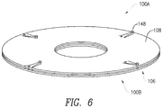
- FIG. 6 is a perspective view of an underside of an example filter device.
- FIG. 7 is a perspective view of an example filter device that is comprised of a plurality of filter devices, such as the filter device of FIGS. 1A-6 .
- FIG. 8 illustrates another example filter device, constructed in accordance with the present disclosure.
- FIGS. 9A and 9B collectively illustrate another example filter device/apparatus disposed between a collapsed configuration and an expanded configuration.
- FIG. 10 illustrates an additional example filter device, constructed in accordance with the present disclosure.
- FIG. 11 is a close up perspective view of the example filter device of FIG. 10 , illustrating filter rows with microstructure filter members.
- FIG. 12 is a close up perspective view of the example filter device of FIG. 11 , illustrating the microstructure filter members as posts arranged in a zig-zag configuration.
- FIG. 13 is a close up perspective view of another example filter device, illustrating the microstructure filter members as posts arranged in a linear configuration.
- FIG. 14 is a perspective view of another example filter device that comprises microstructure filter members manufactured by grooves cut into the filter rows.
- FIGS. 15 and 16 collectively illustrate a perspective view of another example filter device that comprises filter rows of alternating size.
- FIGS. 17 and 18 collectively illustrate a perspective view of another example filter device that comprises apertures or drain holes within the filter rows.
- FIG. 19 is a cross sectional view of an example filter device that comprises filter rows on an upper surface and filter rows on a lower surface.
- the present disclosure is generally directed to filters and filtering apparatuses comprised of a plurality of filter devices, and methods for using the same. These filters are used for filtering particular matter from a fluid.
- the filter devices include permutations of primary, secondary, tertiary, and quaternary inlet and/or outlet channels.
- One or more embodiments comprise rows of microstructure filtering members that filter particulates from a fluid flowing across and/or through various parts of the filter device.
- Any fluid that bears particulate matter can be processed using the filter devices and filter structures/apparatuses of the present disclosure.
- FIGS. 1A and 1B collectively illustrate an example filter device 100 .
- the filter device 100 comprises a base structure 102 and a plurality of filter rows, such as filter row 104 .
- the base structure 102 can include a disk of material manufactured from any desired material.
- the base structure 102 can include a dielectric material, whereas in other embodiments a conductive material can be utilized.
- the base structure 102 can be charged to attract particles within the fluid.
- the base structure 102 is electrically charged to create an electric field across a fluid as it flows along or through the base structure 102 .
- the electrical charge can also cause particle attraction in the plurality of filter TOWS.
- the base structure 102 and/or the plurality of filter rows can be coated or manufactured from a material that causes chemical attraction of particulates rather than (or in addition to) electrical attraction of the particles.
- the base structure 102 is provided with an upper surface 106 and a lower surface 108 (illustrated in FIG. 6 ), which are spaced apart from one another based on a thickness of the base structure 102 and the plurality of filter rows.
- the filter device 100 is illustrated as having an annular shape, the filter device 100 can include any other desired shape such as triangular, rectangular, circular, square, polygonal and irregular.
- the base structure 102 comprises a central aperture 110 that defines either a primary inlet or outlet boundary B 1 .
- An outer peripheral edge 112 of the base structure 102 defines a complimentary a primary inlet or outlet boundary B 2 .
- B 1 is the primary inlet and B 2 is the primary outlet.
- B 2 is the primary inlet and B 1 is the primary outlet.
- the base structure 102 is ringed with a plurality of rib protrusions, such as protrusion 114 that define spaces that allow for filtering large particles from a fluid. This is advantageous when the primary inlet boundary is defined by the outer peripheral edge 112 of the base structure 102 .
- the plurality of filter rows can be created by any manufacturing process that allows material to be removed from a blank of material that is transformed into the filter device.
- the plurality of filter rows is created from depositing material onto the base structure 102 , using any one or more methods which would be known to one of ordinary skill in the art with the present disclosure before them.
- the plurality of filter rows provides paths of fluid flow across and through the plurality of filter rows.
- the plurality of filter rows can be arranged in v-shaped configurations and disposed on the base structure 102 so as to cover a portion of the upper surface 106 .
- spaces between adjacent filter rows, such as space 116 include an aperture fabricated into the base structure 102 so as to provide a path of fluid communication through the filter device 100 , passing from the upper surface 106 to lower surface 108 .
- spaces such as space 116 and its corresponding aperture are illustrated along with a fluid flow direction where the primary inlet boundary is defined by the outer peripheral edge 112 .
- the filter row 104 comprises microstructure filter members arranged into blocks, such as block 118 and block 120 .
- a primary block 122 links two filter rows together.
- the microstructures are not illustrated in FIG. 3 for purposes of clarity, but are illustrated in various embodiments herein.
- block 118 and block 120 are in fluid communication with one another (and other adjacent blocks) using inlet ports and outlet ports, such as outlet port 124 of block 118 that couples to inlet port 126 of block 120 .
- Adjacent microstructure filter blocks also define a secondary inlet channel and a secondary outlet channels.
- block 118 and block 120 define a secondary inlet channel 128 and a secondary outlet channel 130 .
- the spaces between filter rows can function also as primary inlet and/or outlet channels.
- FIG. 4 illustrates microstructures 132 of block 118 .
- FIG. 5 illustrates rows of microstructures such as adjacent rows 134 and 136 .
- the adjacent rows of microstructures define tertiary inlet and outlet channels, such as tertiary inlet channel 138 and tertiary outlet channel 140 .
- each row such as row 134 comprises two offset rows of posts 142 .
- quaternary inlet and outlet channels are defined by actual microstructures features. Thus, flow across the microstructure features flows from the quaternary inlets to the quaternary outlets. In one example, quaternary inlets 144 and quaternary outlets 146 are illustrated across two rows of microstructures features.
- the microstructure filter members are covered with a covering or layer that partially encloses the microstructure filter member blocks to increase fluid pressure and therefore fluid velocity through the microstructure filter members.
- the layer or covering can also be provided by a lower surface of an adjacent filter device, which is disposed above the filter device 100 , when a plurality of filter devices are stacked together.
- FIG. 6 illustrates two filter devices 100 A and 100 B (two of the filter devices 100 of FIGS. 1-5 ) comprising a plurality of spacers, such as spacer 148 .
- the spacers include resilient bodies in some instances.
- the spacers are resiliently biased to allow adjacent, stacked filter devices 100 A and 100 B to be spaced apart from one another but compressed in some applications.
- FIG. 7 illustrates an example filter device 200 that includes a plurality of filter devices, such as the filter device 100 of FIGS. 1A-6 .
- the inclusion of the resilient spacers allows the filter device 200 to be compressed into a collapsed configuration.
- the filter devices are compressed into contacting or mating configuration, where a lower surface of one filter device contacts the plurality of filter rows of a lower positioned filter device. This contacting or mating configuration allows for filtering of a fluid flowing through or across the individual filter devices that comprise the filter device 200 .
- FIG. 8 illustrates another example filter device 300 that is similar in construction to the filter device 100 of FIGS. 1A-6 with the exception that the base structure 302 does not include apertures in the spaces between the plurality of filter rows of microstructure features. Thus, other than a central aperture, the base structure is continuous.
- FIG. 9A illustrates another filter device/apparatus 200 in a compressed configuration.
- the example filter device/apparatus 200 is disposed in an expanded configuration, which allows for cleaning of the plurality of filter devices by exposing the plurality of filter rows and the microstructure features of the plurality of filter rows to a cleaning fluid.
- a cleaning fluid can be sprayed across the plurality of filter rows and the microstructure features to remove the particulate matter isolated by the base structure, plurality of filter rows, microstructure features, or other features of the filter devices such as rib protrusions and the like.
- FIG. 10 illustrates another example filter device 400 that includes a base structure 402 that is constructed as a disk of material, although as mentioned above other shapes are also likewise contemplated for use.
- the base structure 402 is provided with a plurality of filter rows, such as filter row 404 that extend between a central aperture 406 defined by an inner peripheral edge 408 of the base structure 402 and an outer peripheral edge 410 of the base structure 402 .
- the filter rows extend around the base structure in a fan pattern comprised of a series of connected v-shaped structures.
- a closer view of a portion of the plurality of filter rows illustrates microstructures 412 .
- these microstructure features can include grooves cut into the filter row material. That is, the plurality of filter rows are solid structures and grooves are manufactured into the structural material to create the microstructures 412 .
- FIG. 12 Another example filter device 500 is illustrated in FIG. 12 where a plurality of filter rows 502 include microstructures 504 constructed of posts 506 that are deposited onto the filter rows 502 . In one embodiment, a notch is fabricated into each of the filter rows 502 to accommodate the posts 506 . In FIG. 12 the posts 506 are arranged into a zig-zag or v-shaped pattern. The posts 506 create tertiary inlet channels 508 and tertiary outlet channels 510 . These tertiary inlet channels 508 and tertiary outlet channels 510 are in fluid communication with secondary inlet channels 512 and secondary outlet channels 514 . Again, the defining consideration as to whether a channel is an inlet or outlet channel is dependent on the direction of fluid flow across or through the filter device 500 . Thus, the designation of secondary inlet channels 512 and secondary outlet channels 514 is exemplary and not limiting.
- FIG. 13 illustrates an example filter device 600 that includes linear post microstructures 602 .
- FIG. 14 illustrates an example filter device 700 that includes post style microstructures 702 arranged in a groove style configuration.
- microstructure features in terms of numbers, placement, spacing, and the like are determined based on the filtering criteria established for the filter device.
- the microstructure features may be placed closer together and in greater numbers, as well as being arranged in more complicated patterns so as to prevent the passage of particles through the microstructure filters.
- an individual filter row can include different permutations of microstructure features where larger sized and wider spaced microstructure features are included on one portion of the filter row while smaller sized and more narrowly spaced microstructure features are disposed on another portion of the filter row.
- the smaller sized and more narrowly spaced microstructure features can be located near the outlet boundary in some embodiments.
- an example filter device 800 includes a plurality of filter rows 802 that alternate in length such that a first portion of the plurality of filter rows, such as row 804 , extend from an inner peripheral edge 806 of a base structure 808 to an outer peripheral edge 810 of the base structure 808 .
- the overall length between the inner peripheral edge 806 and the outer peripheral edge 810 defines a first length L 1
- a second portion of the plurality of filter rows, such as row 804 extend from the outer peripheral edge 810 of the base structure 808 at a second length L 2 that is less than the first length L 1 .
- the shorter ones of the filter rows are disposed within the longer ones of the filter rows, in some embodiments.
- an example filter device 900 includes a plurality of filter rows 902 .
- An aperture, such as aperture 904 is disposed between each adjoining pair of filter rows, such as rows 906 and 908 .
- the apertures are located near an inner peripheral edge 910 , although other aperture placements and/or numbers of apertures can be utilized.
- FIG. 19 illustrates another example filter device 1000 that comprises a base structure 1002 that can be constructed similarly to other base structures (such as base structure 102 of FIG. 1A ).
- the device 1000 comprises a plurality of filter rows such as filter row 1004 , which are disposed on an upper surface 1006 of the base structure 1002 .
- the device 1000 also comprises a plurality of filter rows such as filter row 1008 , which are disposed on a lower surface 1010 of the base structure 1002 .
- filter rows are disposed on both the upper and lower surfaces of the base structure 1002 .
- the filter rows on the upper and lower surfaces can be similar in structure to one another, while in other embodiments the filter rows on the upper surface 1006 can have different geometrical (or microstructure features) configurations than those provided on the lower surface 1010 .
- a hyphenated term (e.g., “on-demand”) may be occasionally interchangeably used with its non-hyphenated version (e.g., “on demand”)
- a capitalized entry e.g., “Software”
- a non-capitalized version e.g., “software”
- a plural term may be indicated with or without an apostrophe (e.g., PE's or PEs)
- an italicized term e.g., “N+1” may be interchangeably used with its non-italicized version (e.g., “N+1”).
- Such occasional interchangeable uses shall not be considered inconsistent with each other.
- a “means for” performing a task or set of tasks. It will be understood that a “means for” may be expressed herein in terms of a structure, device, assembly, sub-assembly, component, and combinations thereof. Alternatively, in some embodiments the “means for” is expressed in terms of prose, or as a flow chart or a diagram.
- first, second, etc. may be used herein to describe various elements, components, regions, layers and/or sections, these elements, components, regions, layers and/or sections should not necessarily be limited by such terms. These terms are only used to distinguish one element, component, region, layer or section from another element, component, region, layer or section. Thus, a first element, component, region, layer or section discussed below could be termed a second element, component, region, layer or section without departing from the teachings of the present disclosure.
- Example embodiments of the present disclosure are described herein with reference to illustrations of idealized embodiments (and intermediate structures) of the present disclosure. As such, variations from the shapes of the illustrations as a result, for example, of manufacturing techniques and/or tolerances, are to be expected. Thus, the example embodiments of the present disclosure should not be construed as necessarily limited to the particular shapes of regions illustrated herein, but are to include deviations in shapes that result, for example, from manufacturing.
- Any and/or all elements, as disclosed herein, can be formed from a same, structurally continuous piece, such as being unitary, and/or be separately manufactured and/or connected, such as being an assembly and/or modules. Any and/or all elements, as disclosed herein, can be manufactured via any manufacturing processes, whether additive manufacturing, subtractive manufacturing and/or other any other types of manufacturing. For example, some manufacturing processes include three dimensional (3D) printing, laser cutting, computer numerical control (CNC) routing, milling, pressing, stamping, vacuum forming, hydroforming, injection molding, lithography and/or others.
- 3D three dimensional
- CNC computer numerical control
- any and/or all elements, as disclosed herein, can include, whether partially and/or fully, a solid, including a metal, a mineral, a ceramic, an amorphous solid, such as glass, a glass ceramic, an organic solid, such as wood and/or a polymer, such as rubber, a composite material, a semiconductor, a nano-material, a biomaterial and/or any combinations thereof.
- a solid including a metal, a mineral, a ceramic, an amorphous solid, such as glass, a glass ceramic, an organic solid, such as wood and/or a polymer, such as rubber, a composite material, a semiconductor, a nano-material, a biomaterial and/or any combinations thereof.
- any and/or all elements, as disclosed herein, can include, whether partially and/or fully, a coating, including an informational coating, such as ink, an adhesive coating, a melt-adhesive coating, such as vacuum seal and/or heat seal, a release coating, such as tape liner, a low surface energy coating, an optical coating, such as for tint, color, hue, saturation, tone, shade, transparency, translucency, non-transparency, luminescence, anti-reflection and/or holographic, a photo-sensitive coating, an electronic and/or thermal property coating, such as for passivity, insulation, resistance or conduction, a magnetic coating, a water-resistant and/or waterproof coating, a scent coating and/or any combinations thereof.
- a coating including an informational coating, such as ink, an adhesive coating, a melt-adhesive coating, such as vacuum seal and/or heat seal, a release coating, such as tape liner, a low surface energy coating, an optical coating, such as for tint, color, hue
- relative terms such as “below,” “lower,” “above,” and “upper” may be used herein to describe one element's relationship to another element as illustrated in the accompanying drawings. Such relative terms are intended to encompass different orientations of illustrated technologies in addition to the orientation depicted in the accompanying drawings. For example, if a device in the accompanying drawings is turned over, then the elements described as being on the “lower” side of other elements would then be oriented on “upper” sides of the other elements. Similarly, if the device in one of the figures is turned over, elements described as “below” or “beneath” other elements would then be oriented “above” the other elements. Therefore, the example terms “below” and “lower” can, therefore, encompass both an orientation of above and below.
Abstract
Description
Claims (21)
Priority Applications (1)
| Application Number | Priority Date | Filing Date | Title |
|---|---|---|---|
| US15/045,119 US10758849B2 (en) | 2015-02-18 | 2016-02-16 | Three dimensional filter devices and apparatuses |
Applications Claiming Priority (2)
| Application Number | Priority Date | Filing Date | Title |
|---|---|---|---|
| US201562176420P | 2015-02-18 | 2015-02-18 | |
| US15/045,119 US10758849B2 (en) | 2015-02-18 | 2016-02-16 | Three dimensional filter devices and apparatuses |
Publications (2)
| Publication Number | Publication Date |
|---|---|
| US20160236120A1 US20160236120A1 (en) | 2016-08-18 |
| US10758849B2 true US10758849B2 (en) | 2020-09-01 |
Family
ID=56620646
Family Applications (1)
| Application Number | Title | Priority Date | Filing Date |
|---|---|---|---|
| US15/045,119 Active 2036-05-17 US10758849B2 (en) | 2015-02-18 | 2016-02-16 | Three dimensional filter devices and apparatuses |
Country Status (2)
| Country | Link |
|---|---|
| US (1) | US10758849B2 (en) |
| WO (1) | WO2016133929A1 (en) |
Cited By (1)
| Publication number | Priority date | Publication date | Assignee | Title |
|---|---|---|---|---|
| US20220347603A1 (en) * | 2021-04-30 | 2022-11-03 | Pall Corporation | Filter disk segments |
Families Citing this family (10)
| Publication number | Priority date | Publication date | Assignee | Title |
|---|---|---|---|---|
| US10040018B2 (en) | 2013-01-09 | 2018-08-07 | Imagine Tf, Llc | Fluid filters and methods of use |
| US9861920B1 (en) | 2015-05-01 | 2018-01-09 | Imagine Tf, Llc | Three dimensional nanometer filters and methods of use |
| US10730047B2 (en) | 2014-06-24 | 2020-08-04 | Imagine Tf, Llc | Micro-channel fluid filters and methods of use |
| US10124275B2 (en) | 2014-09-05 | 2018-11-13 | Imagine Tf, Llc | Microstructure separation filters |
| US10758849B2 (en) | 2015-02-18 | 2020-09-01 | Imagine Tf, Llc | Three dimensional filter devices and apparatuses |
| US10118842B2 (en) | 2015-07-09 | 2018-11-06 | Imagine Tf, Llc | Deionizing fluid filter devices and methods of use |
| US10479046B2 (en) | 2015-08-19 | 2019-11-19 | Imagine Tf, Llc | Absorbent microstructure arrays and methods of use |
| US11020690B2 (en) | 2018-12-06 | 2021-06-01 | Caterpillar Inc. | 3D printed filter center tube |
| US10981335B2 (en) * | 2019-02-06 | 2021-04-20 | Caterpillar Inc. | Filtration media packs produced using additive manufacturing |
| US11684874B2 (en) * | 2020-12-29 | 2023-06-27 | Metal Industries Research & Development Centre | Tangential flow filtration module and tangential flow filtration assembly |
Citations (132)
| Publication number | Priority date | Publication date | Assignee | Title |
|---|---|---|---|---|
| US1977174A (en) | 1933-10-19 | 1934-10-16 | Victor R Heftler | Filter |
| US3250396A (en) | 1964-08-12 | 1966-05-10 | Ametek Inc | Rotary disc filter |
| US3335946A (en) | 1964-04-14 | 1967-08-15 | Ceskoslovenska Akademie Ved | Separating disks for centrifuges |
| DE1270004B (en) * | 1964-12-21 | 1968-06-12 | M Jacques Muller | Filter element |
| US3884805A (en) | 1974-05-13 | 1975-05-20 | Artisan Ind | Apparatus and process for continuous concentration of solids from a solids-containing fluid |
| US3948779A (en) | 1972-12-29 | 1976-04-06 | Jackson Clifford E | Disc filter |
| US4267045A (en) * | 1978-10-26 | 1981-05-12 | The Babcock & Wilcox Company | Labyrinth disk stack having disks with integral filter screens |
| US4410430A (en) | 1981-05-11 | 1983-10-18 | California Institute Of Technology | Stacked-disc structure for fluid filter or valve silencer |
| US4423090A (en) | 1982-02-02 | 1983-12-27 | General Motors Corporation | Method of making wall-flow monolith filter |
| US4430232A (en) * | 1981-02-04 | 1984-02-07 | Charles Doucet | Disc filter for liquids |
| US4478769A (en) | 1982-09-30 | 1984-10-23 | Amerace Corporation | Method for forming an embossing tool with an optically precise pattern |
| US4486363A (en) | 1982-09-30 | 1984-12-04 | Amerace Corporation | Method and apparatus for embossing a precision optical pattern in a resinous sheet |
| US4601861A (en) | 1982-09-30 | 1986-07-22 | Amerace Corporation | Methods and apparatus for embossing a precision optical pattern in a resinous sheet or laminate |
| US4620917A (en) | 1982-02-08 | 1986-11-04 | Nippon Soken, Inc. | Electrostatic filtering device |
| US4668558A (en) | 1978-07-20 | 1987-05-26 | Minnesota Mining And Manufacturing Company | Shaped plastic articles having replicated microstructure surfaces |
| US4797175A (en) | 1987-03-09 | 1989-01-10 | Hughes Aircraft Company | Method for making solid element fluid filter for removing small particles from fluids |
| US4842739A (en) | 1987-08-20 | 1989-06-27 | Minnesota Mining And Manufacturing Company | High surface area filter cartridge |
| US4842794A (en) | 1987-07-30 | 1989-06-27 | Applied Extrusion Technologies, Inc. | Method of making apertured films and net like fabrics |
| US4891120A (en) | 1986-06-06 | 1990-01-02 | Sethi Rajinder S | Chromatographic separation device |
| US4902420A (en) | 1987-03-27 | 1990-02-20 | Pall Corporation | Segmented filter disc with slotted support and drainage plate and support spacer |
| US4960449A (en) | 1989-02-28 | 1990-10-02 | Cummins Engine Company, Inc. | Ceramic particulate trap and method of making the same |
| US4971769A (en) | 1988-08-20 | 1990-11-20 | Schwaebische Huettenwerke Gmbh | Filter device for use in heating or incineration plants |
| US5009857A (en) | 1988-03-10 | 1991-04-23 | Schwaebische Huettenwerke Gmbh | Filter for gases |
| US5100551A (en) | 1987-03-27 | 1992-03-31 | Pall Corporation | Segmented filter disc with slotted support and drainage plate |
| US5200073A (en) | 1991-02-22 | 1993-04-06 | Gelman Sciences Inc. | Polymeric film filter assembly |
| US5204690A (en) | 1991-07-01 | 1993-04-20 | Xerox Corporation | Ink jet printhead having intergral silicon filter |
| US5207962A (en) | 1991-06-25 | 1993-05-04 | Applied Extrusion Technologies, Inc. | Method of making apertured film fabrics |
| US5262107A (en) | 1991-06-25 | 1993-11-16 | Applied Extrusion Technologies, Inc. | Method of making apertured film fabrics |
| US5290447A (en) | 1990-02-08 | 1994-03-01 | Lippold Hans Joachim | Block-shaped pleated filter insert |
| US5505852A (en) | 1992-03-04 | 1996-04-09 | Minnesota Mining And Manufacturing Company | Filter element for the filtration of fluids |
| EP0639223B1 (en) | 1992-05-01 | 1996-07-03 | The Trustees Of The University Of Pennsylvania | Microfabricated sperm handling devices |
| US5552046A (en) | 1995-01-23 | 1996-09-03 | Johnston; Arthur W. | Multi-stage microbiological water filter |
| US5568819A (en) | 1993-06-11 | 1996-10-29 | R. J. Reynolds Tobacco Company | Cigarette filter |
| US5645704A (en) | 1994-05-03 | 1997-07-08 | Eugene Sandler | Electrostatic filter device |
| US5858231A (en) * | 1987-02-10 | 1999-01-12 | Drori; Mordeki | Filter apparatus |
| US5985164A (en) | 1994-03-07 | 1999-11-16 | Regents Of The University Of California | Method for forming a filter |
| US6274035B1 (en) | 1999-03-23 | 2001-08-14 | Sidney W. K. Yuan | Biological filtration using parallel sheets |
| US6273938B1 (en) | 1999-08-13 | 2001-08-14 | 3M Innovative Properties Company | Channel flow filter |
| US6284072B1 (en) | 1996-11-09 | 2001-09-04 | Epigem Limited | Multifunctional microstructures and preparation thereof |
| US6306300B1 (en) | 1997-09-06 | 2001-10-23 | William Henry Harding | Filter cartridges and filter cells |
| US6346192B2 (en) | 1999-05-14 | 2002-02-12 | Therox, Inc. | Apparatus for high pressure fluid filtration |
| EP1196242A1 (en) | 1999-06-08 | 2002-04-17 | Bayer Aktiengesellschaft | Catalysts based on organic-inorganic hybrid materials containing titanium, for the selective oxidation of hydrocarbons |
| EP1197255A1 (en) | 2000-10-11 | 2002-04-17 | 3M Innovative Properties Company | Combination filter system including flow channel filtration media and an absorber particle filtration medium |
| US6375870B1 (en) | 1998-11-17 | 2002-04-23 | Corning Incorporated | Replicating a nanoscale pattern |
| US6391097B1 (en) * | 1999-06-18 | 2002-05-21 | Gideon Rosenberg | Filtration disc including electric field formation |
| US20020060183A1 (en) | 2000-09-15 | 2002-05-23 | Paul C. Thomas | Spiral pleated filter cartridges |
| US20020125192A1 (en) | 2001-02-14 | 2002-09-12 | Lopez Gabriel P. | Nanostructured devices for separation and analysis |
| US6471746B2 (en) | 1999-10-19 | 2002-10-29 | 3M Innovative Properties Company | Electrofiltration process |
| US20020185003A1 (en) | 2001-06-11 | 2002-12-12 | Rochester Institute Of Technology | Electrostatic filter and a method thereof |
| US6524488B1 (en) | 1998-06-18 | 2003-02-25 | 3M Innovative Properties Company | Method of filtering certain particles from a fluid using a depth loading filtration media |
| US20030104170A1 (en) | 2001-02-07 | 2003-06-05 | 3M Innovative Properties Company | Microstructured surface film assembly for liquid acquisition and transport |
| US20030118781A1 (en) | 1999-01-29 | 2003-06-26 | Minnesota Mining And Manufacturing Company | Contoured layer channel flow filtration media |
| US6589317B2 (en) | 2001-08-10 | 2003-07-08 | 3M Innovative Properties Company | Structured surface filtration media array |
| US6632357B1 (en) | 1999-11-18 | 2003-10-14 | University Of South Florida | Reverse osmosis (“RO”) membrane system incorporating function of flow channel spacer |
| US6685833B2 (en) | 2000-09-21 | 2004-02-03 | Lpd Technologies, Inc. | Fluid filter element |
| US6746890B2 (en) | 2002-07-17 | 2004-06-08 | Tini Alloy Company | Three dimensional thin film devices and methods of fabrication |
| US6748978B2 (en) | 2001-04-20 | 2004-06-15 | Nanostream, Inc. | Microfluidic devices with porous regions |
| US6761962B2 (en) | 1998-06-18 | 2004-07-13 | 3M Innovative Properties Company | Microfluidic articles |
| US20040159319A1 (en) | 1997-09-26 | 2004-08-19 | Boehringer Ingelheim International Gmbh | Microstructured filter |
| EP1449585A1 (en) | 1999-07-07 | 2004-08-25 | 3M Innovative Properties Company | Microfluidic article |
| US6827906B1 (en) | 1997-10-15 | 2004-12-07 | Aclara Biosciences, Inc. | Continuous form microstructure assay array |
| US6872302B2 (en) | 2002-03-15 | 2005-03-29 | Alfatech S.P.A. | Chromatographic apparatus |
| US6915566B2 (en) | 1999-03-01 | 2005-07-12 | Texas Instruments Incorporated | Method of fabricating flexible circuits for integrated circuit interconnections |
| US20050179150A1 (en) | 2003-01-06 | 2005-08-18 | Bharadwaj Rishikesh K. | Embossed oriented optical films |
| US6936086B2 (en) | 2002-09-11 | 2005-08-30 | Planar Systems, Inc. | High conductivity particle filter |
| US7032426B2 (en) | 2000-08-17 | 2006-04-25 | Industrial Origami, Llc | Techniques for designing and manufacturing precision-folded, high strength, fatigue-resistant structures and sheet therefor |
| US7048848B2 (en) | 2001-03-20 | 2006-05-23 | Norbert Assion | Hybrid spin-on filter |
| US7081208B2 (en) | 2002-12-16 | 2006-07-25 | International Business Machines Corporation | Method to build a microfilter |
| US7104406B2 (en) | 2003-08-18 | 2006-09-12 | Industrial Technology Research Institute | Micro-filter for filtering blood cells |
| US20060219627A1 (en) | 2005-03-31 | 2006-10-05 | Rodgers M S | MEMS filter module with concentric filtering walls |
| US7122068B2 (en) | 2001-05-01 | 2006-10-17 | Wix Filtration Corp. | Pleated filter media with embossed spacers and cross flow |
| US7163733B2 (en) | 2004-11-12 | 2007-01-16 | Eastman Kodak Company | Touch screen having spacer dots with channels |
| US20070020772A1 (en) | 2002-04-16 | 2007-01-25 | Princeton University | Gradient structures interfacing microfluidics and nanofluidics, methods for fabrication and uses thereof |
| US7223364B1 (en) | 1999-07-07 | 2007-05-29 | 3M Innovative Properties Company | Detection article having fluid control film |
| US7238255B2 (en) | 2001-12-31 | 2007-07-03 | Gyros Patent Ab | Microfluidic device and its manufacture |
| US20070151920A1 (en) | 2005-12-06 | 2007-07-05 | Kay Ronald J | System and method of micromolded filtration microstructure and devices |
| US7282148B2 (en) | 2003-10-30 | 2007-10-16 | International Business Machines Corporation | Porous silicon composite structure as large filtration array |
| US20070246433A1 (en) | 2005-11-07 | 2007-10-25 | Bilal Zuberi | Refractory Exhaust Filtering Method and Apparatus |
| US20070251867A1 (en) | 2006-04-13 | 2007-11-01 | Mihlbauer Brad L | Aquarium Filter |
| US20080012151A1 (en) | 2003-06-19 | 2008-01-17 | Avantone Oy | Method and an Apparatus for Manufacturing an Electronic Thin-Film Component and an Electronic Thin-Film Component |
| US20080014410A1 (en) | 2006-06-28 | 2008-01-17 | 3M Innovative Properties Company | Oriented Polymeric Articles and Method |
| US7323105B1 (en) | 2004-08-11 | 2008-01-29 | Fleetguard, Inc. | High capacity direct flow filter with maintained channel width |
| US7425227B1 (en) | 2004-06-17 | 2008-09-16 | Wix Filtration Corp Llc | Pleated filter element with offset emboss pattern |
| US7442303B2 (en) | 1999-12-08 | 2008-10-28 | Baxter International Inc. | Microporous filter membrane, method of making microporous filter membrane and separator employing microporous filter membranes |
| US20080296238A1 (en) | 2006-05-31 | 2008-12-04 | Dean Haldopoulos | Modular filter assembly |
| US20090102094A1 (en) | 2001-12-03 | 2009-04-23 | Donaldson Company, Inc. | Media, filter element using corrugated media sheet, corrugated sheet, and methods |
| US7531120B2 (en) | 2000-12-02 | 2009-05-12 | Aquamarijn Holding B.V. | Method of making a product with a micro or nano sized structure and product |
| US20090120874A1 (en) | 2005-05-20 | 2009-05-14 | Peter Holme Jensen | Membrane for filtering of water |
| US20090149345A1 (en) | 2005-03-07 | 2009-06-11 | Kuraray Co., Ltd. | Microchannel array and method for producing the same, and blood measuring method employing it |
| US7588619B2 (en) | 2006-11-28 | 2009-09-15 | Wix Filtration Corp. | Cross-flow filter media and filter assembly |
| US20100028604A1 (en) | 2008-08-01 | 2010-02-04 | The Ohio State University | Hierarchical structures for superhydrophobic surfaces and methods of making |
| US20100216126A1 (en) | 2007-01-12 | 2010-08-26 | Brunel University | Microfluidic device |
| EP1254689B1 (en) | 2001-05-01 | 2010-09-01 | Wix Filtration Corp LLC | Pleated filter media with embossed spacers and cross flow |
| US20100317132A1 (en) | 2009-05-12 | 2010-12-16 | Rogers John A | Printed Assemblies of Ultrathin, Microscale Inorganic Light Emitting Diodes for Deformable and Semitransparent Displays |
| US7901758B2 (en) | 2002-12-13 | 2011-03-08 | Ole-Bendt Rasmussen | Laminates of films having improved resistance to bending in all directions and methods and apparatus for their manufacture |
| US7922795B2 (en) | 2005-04-29 | 2011-04-12 | University Of Rochester | Ultrathin nanoscale membranes, methods of making, and uses thereof |
| US20110100900A1 (en) | 2008-04-28 | 2011-05-05 | Kenneth Joseph Drury | Monolith Membrane Module for Liquid Filtration |
| WO2011066055A2 (en) | 2009-11-24 | 2011-06-03 | Unipixel Displays, Inc. | Formation of electrically conductive pattern by surface energy modification |
| US7959780B2 (en) | 2004-07-26 | 2011-06-14 | Emporia Capital Funding Llc | Textured ion exchange membranes |
| US7988840B2 (en) | 2002-10-23 | 2011-08-02 | The Trustees Of Princeton University | Method for continuous particle separation using obstacle arrays asymmetrically aligned to fields |
| US8025854B2 (en) | 2002-06-07 | 2011-09-27 | Amic Ab | Micro fluidic structures |
| US20110240476A1 (en) | 2008-12-17 | 2011-10-06 | Ding Wang | Fabrication of conductive nanostructures on a flexible substrate |
| US8083941B2 (en) | 2007-08-17 | 2011-12-27 | Huan-Jun Chien | Construction of the wedge filtration media laminated by wedge filter plate |
| US20120006760A1 (en) | 2002-09-27 | 2012-01-12 | Mehmet Toner | Microfluidic device for cell separation and uses thereof |
| US20120037544A1 (en) | 2009-04-23 | 2012-02-16 | Logos Energy, Inc. | Lateral displacement array for microfiltration |
| US8179381B2 (en) | 2008-02-28 | 2012-05-15 | 3M Innovative Properties Company | Touch screen sensor |
| US8186913B2 (en) | 2007-04-16 | 2012-05-29 | The General Hospital Corporation | Systems and methods for particle focusing in microchannels |
| US8273245B2 (en) | 2004-10-06 | 2012-09-25 | State Of Oregon Acting By And Through The State Board Of Higher Education On Behalf Of Oregon State University | Microfluidic devices, particularly filtration devices comprising polymeric membranes, and methods for their manufacture and use |
| US20120244314A1 (en) | 2009-12-14 | 2012-09-27 | 3M Innovative Properties Company | Microperforated polymeric film and methods of making and using the same |
| US20120244311A1 (en) | 2009-12-11 | 2012-09-27 | Astenjohnson, Inc. | Industrial fabric comprised of selectively slit and embossed film |
| US8277759B2 (en) | 2008-03-04 | 2012-10-02 | The University Of Utah Research Foundation | Microfluidic flow cell |
| FR2973257A1 (en) * | 2011-03-31 | 2012-10-05 | Hydro Leduc | Self-cleaning and adjustable-size polluted liquid filter for reciprocating pumping device, has elements whose spacing is adjusted to define size of particles to be passed, or increased to maximum to allow retained particles to be detached |
| US20120261331A1 (en) | 2009-10-19 | 2012-10-18 | Dirk Ter Horst | Embossed fluid filter element |
| US20120261333A1 (en) | 2011-04-13 | 2012-10-18 | Shane James Moran | Filter element for fluid filtration system |
| US20120267249A1 (en) | 2009-10-28 | 2012-10-25 | International Business Machines Corporation | Surface charge enabled nanoporous semi-permeable membrane for desalination |
| US8297449B2 (en) | 2010-01-12 | 2012-10-30 | International Business Machines Corporation | Nanoporous semi-permeable membrane and methods for fabricating the same |
| US20120273990A1 (en) | 2003-08-07 | 2012-11-01 | O'donnell Hugh Joseph | Method and Apparatus for Making an Apertured Web |
| US8328022B2 (en) | 2009-09-07 | 2012-12-11 | Mann + Hummel Gmbh | Filter for filtering fluids |
| US20130008848A1 (en) | 2010-04-14 | 2013-01-10 | Nanospace Ab | Filter comprising stackable filter wafers with filtering channels on opposing sides of the wafers |
| US20130078163A1 (en) | 2011-09-22 | 2013-03-28 | Georgia Tech Research Corporation | Deterministic High-Density Single-Cell Trap Array |
| CN203139755U (en) | 2013-03-22 | 2013-08-21 | 新疆泓科节水设备制造有限公司 | Laminated-type water filter for micro-irrigation |
| US8679336B2 (en) | 2008-11-14 | 2014-03-25 | Fuji Xerox Co., Ltd. | Microchannel device, separation apparatus, and separation method |
| WO2014116183A1 (en) | 2013-01-24 | 2014-07-31 | National University Of Singapore | Microdevices for separation of non-spherical particles and applications thereof |
| US20140221544A1 (en) | 1999-08-04 | 2014-08-07 | Hybrid Plastics, Inc. | Method for Modifying Surface Properties with Nanostructured Chemicals |
| US20140224658A1 (en) | 2013-01-09 | 2014-08-14 | Imagine Tf, Llc | Fluid filters and methods of use |
| US20150367257A1 (en) | 2014-06-24 | 2015-12-24 | Imagine Tf, Llc | Micro-channel fluid filters and methods of use |
| WO2015199663A1 (en) | 2014-06-24 | 2015-12-30 | Imagine Tf, Llc | Micro-channel fluid filters and methods of use |
| US20160067634A1 (en) | 2014-09-05 | 2016-03-10 | Imagine Tf, Llc | Microstructure Separation Filters |
| WO2016037150A1 (en) | 2014-09-05 | 2016-03-10 | Imagine Tf, Llc | Microstructure separation filters |
| WO2016133929A1 (en) | 2015-02-18 | 2016-08-25 | Imagine Tf, Llc | Three dimensional filter devices and apparatuses |
| US20170008781A1 (en) | 2015-07-09 | 2017-01-12 | Imagine Tf, Llc | Deionizing fluid filter devices and methods of use |
| WO2017007734A1 (en) | 2015-07-09 | 2017-01-12 | Imagine Tf, Llc | Deionizing fluid filter devices and methods of use |
-
2016
- 2016-02-16 US US15/045,119 patent/US10758849B2/en active Active
- 2016-02-16 WO PCT/US2016/018119 patent/WO2016133929A1/en active Application Filing
Patent Citations (145)
| Publication number | Priority date | Publication date | Assignee | Title |
|---|---|---|---|---|
| US1977174A (en) | 1933-10-19 | 1934-10-16 | Victor R Heftler | Filter |
| US3335946A (en) | 1964-04-14 | 1967-08-15 | Ceskoslovenska Akademie Ved | Separating disks for centrifuges |
| US3250396A (en) | 1964-08-12 | 1966-05-10 | Ametek Inc | Rotary disc filter |
| DE1270004B (en) * | 1964-12-21 | 1968-06-12 | M Jacques Muller | Filter element |
| US3948779A (en) | 1972-12-29 | 1976-04-06 | Jackson Clifford E | Disc filter |
| US3884805A (en) | 1974-05-13 | 1975-05-20 | Artisan Ind | Apparatus and process for continuous concentration of solids from a solids-containing fluid |
| US4668558A (en) | 1978-07-20 | 1987-05-26 | Minnesota Mining And Manufacturing Company | Shaped plastic articles having replicated microstructure surfaces |
| US4267045A (en) * | 1978-10-26 | 1981-05-12 | The Babcock & Wilcox Company | Labyrinth disk stack having disks with integral filter screens |
| US4430232A (en) * | 1981-02-04 | 1984-02-07 | Charles Doucet | Disc filter for liquids |
| US4410430A (en) | 1981-05-11 | 1983-10-18 | California Institute Of Technology | Stacked-disc structure for fluid filter or valve silencer |
| US4423090A (en) | 1982-02-02 | 1983-12-27 | General Motors Corporation | Method of making wall-flow monolith filter |
| US4620917A (en) | 1982-02-08 | 1986-11-04 | Nippon Soken, Inc. | Electrostatic filtering device |
| US4478769A (en) | 1982-09-30 | 1984-10-23 | Amerace Corporation | Method for forming an embossing tool with an optically precise pattern |
| US4601861A (en) | 1982-09-30 | 1986-07-22 | Amerace Corporation | Methods and apparatus for embossing a precision optical pattern in a resinous sheet or laminate |
| US4486363A (en) | 1982-09-30 | 1984-12-04 | Amerace Corporation | Method and apparatus for embossing a precision optical pattern in a resinous sheet |
| US4891120A (en) | 1986-06-06 | 1990-01-02 | Sethi Rajinder S | Chromatographic separation device |
| US5858231A (en) * | 1987-02-10 | 1999-01-12 | Drori; Mordeki | Filter apparatus |
| US4797175A (en) | 1987-03-09 | 1989-01-10 | Hughes Aircraft Company | Method for making solid element fluid filter for removing small particles from fluids |
| US4902420A (en) | 1987-03-27 | 1990-02-20 | Pall Corporation | Segmented filter disc with slotted support and drainage plate and support spacer |
| US5100551A (en) | 1987-03-27 | 1992-03-31 | Pall Corporation | Segmented filter disc with slotted support and drainage plate |
| US4842794A (en) | 1987-07-30 | 1989-06-27 | Applied Extrusion Technologies, Inc. | Method of making apertured films and net like fabrics |
| US4842739A (en) | 1987-08-20 | 1989-06-27 | Minnesota Mining And Manufacturing Company | High surface area filter cartridge |
| US5009857A (en) | 1988-03-10 | 1991-04-23 | Schwaebische Huettenwerke Gmbh | Filter for gases |
| US4971769A (en) | 1988-08-20 | 1990-11-20 | Schwaebische Huettenwerke Gmbh | Filter device for use in heating or incineration plants |
| US4960449A (en) | 1989-02-28 | 1990-10-02 | Cummins Engine Company, Inc. | Ceramic particulate trap and method of making the same |
| US5290447A (en) | 1990-02-08 | 1994-03-01 | Lippold Hans Joachim | Block-shaped pleated filter insert |
| US5200073A (en) | 1991-02-22 | 1993-04-06 | Gelman Sciences Inc. | Polymeric film filter assembly |
| US5207962A (en) | 1991-06-25 | 1993-05-04 | Applied Extrusion Technologies, Inc. | Method of making apertured film fabrics |
| US5262107A (en) | 1991-06-25 | 1993-11-16 | Applied Extrusion Technologies, Inc. | Method of making apertured film fabrics |
| US5204690A (en) | 1991-07-01 | 1993-04-20 | Xerox Corporation | Ink jet printhead having intergral silicon filter |
| US5505852A (en) | 1992-03-04 | 1996-04-09 | Minnesota Mining And Manufacturing Company | Filter element for the filtration of fluids |
| EP0639223B1 (en) | 1992-05-01 | 1996-07-03 | The Trustees Of The University Of Pennsylvania | Microfabricated sperm handling devices |
| US5568819A (en) | 1993-06-11 | 1996-10-29 | R. J. Reynolds Tobacco Company | Cigarette filter |
| US5985164A (en) | 1994-03-07 | 1999-11-16 | Regents Of The University Of California | Method for forming a filter |
| US5645704A (en) | 1994-05-03 | 1997-07-08 | Eugene Sandler | Electrostatic filter device |
| US5552046A (en) | 1995-01-23 | 1996-09-03 | Johnston; Arthur W. | Multi-stage microbiological water filter |
| US6284072B1 (en) | 1996-11-09 | 2001-09-04 | Epigem Limited | Multifunctional microstructures and preparation thereof |
| US6306300B1 (en) | 1997-09-06 | 2001-10-23 | William Henry Harding | Filter cartridges and filter cells |
| US6977042B2 (en) * | 1997-09-26 | 2005-12-20 | Klaus Kadel | Microstructured filter |
| US7645383B2 (en) | 1997-09-26 | 2010-01-12 | Boehringer Ingelheim International Gmbh | Microstructured filter |
| US20040159319A1 (en) | 1997-09-26 | 2004-08-19 | Boehringer Ingelheim International Gmbh | Microstructured filter |
| US6827906B1 (en) | 1997-10-15 | 2004-12-07 | Aclara Biosciences, Inc. | Continuous form microstructure assay array |
| US6524488B1 (en) | 1998-06-18 | 2003-02-25 | 3M Innovative Properties Company | Method of filtering certain particles from a fluid using a depth loading filtration media |
| US6761962B2 (en) | 1998-06-18 | 2004-07-13 | 3M Innovative Properties Company | Microfluidic articles |
| US6375870B1 (en) | 1998-11-17 | 2002-04-23 | Corning Incorporated | Replicating a nanoscale pattern |
| US6752889B2 (en) | 1999-01-29 | 2004-06-22 | 3M Innovative Properties Company | Contoured layer channel flow filtration media |
| US20030118781A1 (en) | 1999-01-29 | 2003-06-26 | Minnesota Mining And Manufacturing Company | Contoured layer channel flow filtration media |
| US6915566B2 (en) | 1999-03-01 | 2005-07-12 | Texas Instruments Incorporated | Method of fabricating flexible circuits for integrated circuit interconnections |
| US6274035B1 (en) | 1999-03-23 | 2001-08-14 | Sidney W. K. Yuan | Biological filtration using parallel sheets |
| US6346192B2 (en) | 1999-05-14 | 2002-02-12 | Therox, Inc. | Apparatus for high pressure fluid filtration |
| EP1196242A1 (en) | 1999-06-08 | 2002-04-17 | Bayer Aktiengesellschaft | Catalysts based on organic-inorganic hybrid materials containing titanium, for the selective oxidation of hydrocarbons |
| US6391097B1 (en) * | 1999-06-18 | 2002-05-21 | Gideon Rosenberg | Filtration disc including electric field formation |
| US8197775B2 (en) | 1999-07-07 | 2012-06-12 | 3M Innovative Properties Company | Detection article having fluid control film |
| US7223364B1 (en) | 1999-07-07 | 2007-05-29 | 3M Innovative Properties Company | Detection article having fluid control film |
| EP1449585A1 (en) | 1999-07-07 | 2004-08-25 | 3M Innovative Properties Company | Microfluidic article |
| US20140221544A1 (en) | 1999-08-04 | 2014-08-07 | Hybrid Plastics, Inc. | Method for Modifying Surface Properties with Nanostructured Chemicals |
| US6273938B1 (en) | 1999-08-13 | 2001-08-14 | 3M Innovative Properties Company | Channel flow filter |
| US6471746B2 (en) | 1999-10-19 | 2002-10-29 | 3M Innovative Properties Company | Electrofiltration process |
| US6632357B1 (en) | 1999-11-18 | 2003-10-14 | University Of South Florida | Reverse osmosis (“RO”) membrane system incorporating function of flow channel spacer |
| US7442303B2 (en) | 1999-12-08 | 2008-10-28 | Baxter International Inc. | Microporous filter membrane, method of making microporous filter membrane and separator employing microporous filter membranes |
| US7784619B2 (en) | 1999-12-08 | 2010-08-31 | Baxter International Inc. | Method of making microporous filter membrane |
| US7032426B2 (en) | 2000-08-17 | 2006-04-25 | Industrial Origami, Llc | Techniques for designing and manufacturing precision-folded, high strength, fatigue-resistant structures and sheet therefor |
| US20020060183A1 (en) | 2000-09-15 | 2002-05-23 | Paul C. Thomas | Spiral pleated filter cartridges |
| US6685833B2 (en) | 2000-09-21 | 2004-02-03 | Lpd Technologies, Inc. | Fluid filter element |
| EP1197255A1 (en) | 2000-10-11 | 2002-04-17 | 3M Innovative Properties Company | Combination filter system including flow channel filtration media and an absorber particle filtration medium |
| US7531120B2 (en) | 2000-12-02 | 2009-05-12 | Aquamarijn Holding B.V. | Method of making a product with a micro or nano sized structure and product |
| US20030104170A1 (en) | 2001-02-07 | 2003-06-05 | 3M Innovative Properties Company | Microstructured surface film assembly for liquid acquisition and transport |
| US6685841B2 (en) | 2001-02-14 | 2004-02-03 | Gabriel P. Lopez | Nanostructured devices for separation and analysis |
| US20020125192A1 (en) | 2001-02-14 | 2002-09-12 | Lopez Gabriel P. | Nanostructured devices for separation and analysis |
| US7048848B2 (en) | 2001-03-20 | 2006-05-23 | Norbert Assion | Hybrid spin-on filter |
| US6748978B2 (en) | 2001-04-20 | 2004-06-15 | Nanostream, Inc. | Microfluidic devices with porous regions |
| US7122068B2 (en) | 2001-05-01 | 2006-10-17 | Wix Filtration Corp. | Pleated filter media with embossed spacers and cross flow |
| EP1254689B1 (en) | 2001-05-01 | 2010-09-01 | Wix Filtration Corp LLC | Pleated filter media with embossed spacers and cross flow |
| US20020185003A1 (en) | 2001-06-11 | 2002-12-12 | Rochester Institute Of Technology | Electrostatic filter and a method thereof |
| US6589317B2 (en) | 2001-08-10 | 2003-07-08 | 3M Innovative Properties Company | Structured surface filtration media array |
| US20090102094A1 (en) | 2001-12-03 | 2009-04-23 | Donaldson Company, Inc. | Media, filter element using corrugated media sheet, corrugated sheet, and methods |
| US7238255B2 (en) | 2001-12-31 | 2007-07-03 | Gyros Patent Ab | Microfluidic device and its manufacture |
| US6872302B2 (en) | 2002-03-15 | 2005-03-29 | Alfatech S.P.A. | Chromatographic apparatus |
| US20070020772A1 (en) | 2002-04-16 | 2007-01-25 | Princeton University | Gradient structures interfacing microfluidics and nanofluidics, methods for fabrication and uses thereof |
| US7217562B2 (en) | 2002-04-16 | 2007-05-15 | Princeton University | Gradient structures interfacing microfluidics and nanofluidics, methods for fabrication and uses thereof |
| US8025854B2 (en) | 2002-06-07 | 2011-09-27 | Amic Ab | Micro fluidic structures |
| US6746890B2 (en) | 2002-07-17 | 2004-06-08 | Tini Alloy Company | Three dimensional thin film devices and methods of fabrication |
| US6936086B2 (en) | 2002-09-11 | 2005-08-30 | Planar Systems, Inc. | High conductivity particle filter |
| US20120006760A1 (en) | 2002-09-27 | 2012-01-12 | Mehmet Toner | Microfluidic device for cell separation and uses thereof |
| US8304230B2 (en) | 2002-09-27 | 2012-11-06 | The General Hospital Corporation | Microfluidic device for cell separation and uses thereof |
| US7988840B2 (en) | 2002-10-23 | 2011-08-02 | The Trustees Of Princeton University | Method for continuous particle separation using obstacle arrays asymmetrically aligned to fields |
| US8282799B2 (en) | 2002-10-23 | 2012-10-09 | The Trustees Of Princeton University | Method for continuous particle separation using obstacle arrays asymmetrically aligned to fields |
| US7901758B2 (en) | 2002-12-13 | 2011-03-08 | Ole-Bendt Rasmussen | Laminates of films having improved resistance to bending in all directions and methods and apparatus for their manufacture |
| US7081208B2 (en) | 2002-12-16 | 2006-07-25 | International Business Machines Corporation | Method to build a microfilter |
| US20050179150A1 (en) | 2003-01-06 | 2005-08-18 | Bharadwaj Rishikesh K. | Embossed oriented optical films |
| US20080012151A1 (en) | 2003-06-19 | 2008-01-17 | Avantone Oy | Method and an Apparatus for Manufacturing an Electronic Thin-Film Component and an Electronic Thin-Film Component |
| US20120273990A1 (en) | 2003-08-07 | 2012-11-01 | O'donnell Hugh Joseph | Method and Apparatus for Making an Apertured Web |
| US7104406B2 (en) | 2003-08-18 | 2006-09-12 | Industrial Technology Research Institute | Micro-filter for filtering blood cells |
| US7282148B2 (en) | 2003-10-30 | 2007-10-16 | International Business Machines Corporation | Porous silicon composite structure as large filtration array |
| US7425227B1 (en) | 2004-06-17 | 2008-09-16 | Wix Filtration Corp Llc | Pleated filter element with offset emboss pattern |
| US7959780B2 (en) | 2004-07-26 | 2011-06-14 | Emporia Capital Funding Llc | Textured ion exchange membranes |
| US7323105B1 (en) | 2004-08-11 | 2008-01-29 | Fleetguard, Inc. | High capacity direct flow filter with maintained channel width |
| US8273245B2 (en) | 2004-10-06 | 2012-09-25 | State Of Oregon Acting By And Through The State Board Of Higher Education On Behalf Of Oregon State University | Microfluidic devices, particularly filtration devices comprising polymeric membranes, and methods for their manufacture and use |
| US7163733B2 (en) | 2004-11-12 | 2007-01-16 | Eastman Kodak Company | Touch screen having spacer dots with channels |
| US20090149345A1 (en) | 2005-03-07 | 2009-06-11 | Kuraray Co., Ltd. | Microchannel array and method for producing the same, and blood measuring method employing it |
| US20060219627A1 (en) | 2005-03-31 | 2006-10-05 | Rodgers M S | MEMS filter module with concentric filtering walls |
| US7922795B2 (en) | 2005-04-29 | 2011-04-12 | University Of Rochester | Ultrathin nanoscale membranes, methods of making, and uses thereof |
| US7857978B2 (en) | 2005-05-20 | 2010-12-28 | Aquaporin A/S | Membrane for filtering of water |
| US20090120874A1 (en) | 2005-05-20 | 2009-05-14 | Peter Holme Jensen | Membrane for filtering of water |
| US20070246433A1 (en) | 2005-11-07 | 2007-10-25 | Bilal Zuberi | Refractory Exhaust Filtering Method and Apparatus |
| US20070151920A1 (en) | 2005-12-06 | 2007-07-05 | Kay Ronald J | System and method of micromolded filtration microstructure and devices |
| US7569139B2 (en) | 2006-04-13 | 2009-08-04 | Newa Tecno Industria S.R.L. | Aquarium filter assembly and filter element |
| US20070251867A1 (en) | 2006-04-13 | 2007-11-01 | Mihlbauer Brad L | Aquarium Filter |
| US20080296238A1 (en) | 2006-05-31 | 2008-12-04 | Dean Haldopoulos | Modular filter assembly |
| US20080014410A1 (en) | 2006-06-28 | 2008-01-17 | 3M Innovative Properties Company | Oriented Polymeric Articles and Method |
| US7588619B2 (en) | 2006-11-28 | 2009-09-15 | Wix Filtration Corp. | Cross-flow filter media and filter assembly |
| US20100216126A1 (en) | 2007-01-12 | 2010-08-26 | Brunel University | Microfluidic device |
| US8186913B2 (en) | 2007-04-16 | 2012-05-29 | The General Hospital Corporation | Systems and methods for particle focusing in microchannels |
| US8083941B2 (en) | 2007-08-17 | 2011-12-27 | Huan-Jun Chien | Construction of the wedge filtration media laminated by wedge filter plate |
| US8179381B2 (en) | 2008-02-28 | 2012-05-15 | 3M Innovative Properties Company | Touch screen sensor |
| US8277759B2 (en) | 2008-03-04 | 2012-10-02 | The University Of Utah Research Foundation | Microfluidic flow cell |
| US20110100900A1 (en) | 2008-04-28 | 2011-05-05 | Kenneth Joseph Drury | Monolith Membrane Module for Liquid Filtration |
| US20100028604A1 (en) | 2008-08-01 | 2010-02-04 | The Ohio State University | Hierarchical structures for superhydrophobic surfaces and methods of making |
| US8679336B2 (en) | 2008-11-14 | 2014-03-25 | Fuji Xerox Co., Ltd. | Microchannel device, separation apparatus, and separation method |
| US20110240476A1 (en) | 2008-12-17 | 2011-10-06 | Ding Wang | Fabrication of conductive nanostructures on a flexible substrate |
| US20120037544A1 (en) | 2009-04-23 | 2012-02-16 | Logos Energy, Inc. | Lateral displacement array for microfiltration |
| US20100317132A1 (en) | 2009-05-12 | 2010-12-16 | Rogers John A | Printed Assemblies of Ultrathin, Microscale Inorganic Light Emitting Diodes for Deformable and Semitransparent Displays |
| US8328022B2 (en) | 2009-09-07 | 2012-12-11 | Mann + Hummel Gmbh | Filter for filtering fluids |
| US20120261331A1 (en) | 2009-10-19 | 2012-10-18 | Dirk Ter Horst | Embossed fluid filter element |
| US20120267249A1 (en) | 2009-10-28 | 2012-10-25 | International Business Machines Corporation | Surface charge enabled nanoporous semi-permeable membrane for desalination |
| EP2505047A2 (en) | 2009-11-24 | 2012-10-03 | Uni-Pixel Displays, Inc. | Formation of electrically conductive pattern by surface energy modification |
| WO2011066055A2 (en) | 2009-11-24 | 2011-06-03 | Unipixel Displays, Inc. | Formation of electrically conductive pattern by surface energy modification |
| US20120244311A1 (en) | 2009-12-11 | 2012-09-27 | Astenjohnson, Inc. | Industrial fabric comprised of selectively slit and embossed film |
| US20120244314A1 (en) | 2009-12-14 | 2012-09-27 | 3M Innovative Properties Company | Microperforated polymeric film and methods of making and using the same |
| US8297449B2 (en) | 2010-01-12 | 2012-10-30 | International Business Machines Corporation | Nanoporous semi-permeable membrane and methods for fabricating the same |
| US20130008848A1 (en) | 2010-04-14 | 2013-01-10 | Nanospace Ab | Filter comprising stackable filter wafers with filtering channels on opposing sides of the wafers |
| FR2973257A1 (en) * | 2011-03-31 | 2012-10-05 | Hydro Leduc | Self-cleaning and adjustable-size polluted liquid filter for reciprocating pumping device, has elements whose spacing is adjusted to define size of particles to be passed, or increased to maximum to allow retained particles to be detached |
| US20120261333A1 (en) | 2011-04-13 | 2012-10-18 | Shane James Moran | Filter element for fluid filtration system |
| US20130078163A1 (en) | 2011-09-22 | 2013-03-28 | Georgia Tech Research Corporation | Deterministic High-Density Single-Cell Trap Array |
| US20140224658A1 (en) | 2013-01-09 | 2014-08-14 | Imagine Tf, Llc | Fluid filters and methods of use |
| WO2015105524A1 (en) | 2013-01-09 | 2015-07-16 | Imagine Tf, Llc | Fluid filters and methods of use |
| WO2014116183A1 (en) | 2013-01-24 | 2014-07-31 | National University Of Singapore | Microdevices for separation of non-spherical particles and applications thereof |
| CN203139755U (en) | 2013-03-22 | 2013-08-21 | 新疆泓科节水设备制造有限公司 | Laminated-type water filter for micro-irrigation |
| US20150367257A1 (en) | 2014-06-24 | 2015-12-24 | Imagine Tf, Llc | Micro-channel fluid filters and methods of use |
| WO2015199663A1 (en) | 2014-06-24 | 2015-12-30 | Imagine Tf, Llc | Micro-channel fluid filters and methods of use |
| US20160067634A1 (en) | 2014-09-05 | 2016-03-10 | Imagine Tf, Llc | Microstructure Separation Filters |
| WO2016037150A1 (en) | 2014-09-05 | 2016-03-10 | Imagine Tf, Llc | Microstructure separation filters |
| WO2016133929A1 (en) | 2015-02-18 | 2016-08-25 | Imagine Tf, Llc | Three dimensional filter devices and apparatuses |
| US20170008781A1 (en) | 2015-07-09 | 2017-01-12 | Imagine Tf, Llc | Deionizing fluid filter devices and methods of use |
| WO2017007734A1 (en) | 2015-07-09 | 2017-01-12 | Imagine Tf, Llc | Deionizing fluid filter devices and methods of use |
Non-Patent Citations (12)
| Title |
|---|
| Brown, R.C. "Electrically Charged Filter Materials." Engineering Science and Education Journal 1.2 (1992): 71. * |
| English Machine Translation of CN 203139755. * |
| English Machine Translation of FR-2973257-A1. * |
| English Translation of DE-1270004-B. * |
| International Search Report and Written Opinion dated Aug. 28, 2014 in Application No. PCT/US2014/036439, filed May 1, 2014. |
| International Search Report and Written Opinion dated Dec. 1, 2014 in Application No. PCT/US2014/043942, filed Jun. 24, 2014. |
| International Search Report and Written Opinion dated Dec. 17, 2015 in Application No. PCT/US2015/048723, filed Sep. 4, 2015. |
| International Search Report and Written Opinion dated May 19, 2016 in Application No. PCT/US2016/018119, filed Feb. 16, 2016, 10 pages. |
| Non-Final Office Action, dated Dec. 21, 2016, U.S. Appl. No. 14/701,528, filed May 1, 2015. |
| Non-Final Office Action, dated Jan. 12, 2017, U.S. Appl. No. 14/313,924, filed Jun. 25, 2014. |
| Non-Final Office Action, dated Jan. 25, 2017, U.S. Appl. No. 15/233,701, filed Aug. 10, 2016. |
| Patent Cooperation Treaty Application No. PCT/US2016/040878, "International Search Report" and "Written Opinion of the International Searching Authority," dated Sep. 19, 2016, 11 pages. |
Cited By (1)
| Publication number | Priority date | Publication date | Assignee | Title |
|---|---|---|---|---|
| US20220347603A1 (en) * | 2021-04-30 | 2022-11-03 | Pall Corporation | Filter disk segments |
Also Published As
| Publication number | Publication date |
|---|---|
| WO2016133929A1 (en) | 2016-08-25 |
| US20160236120A1 (en) | 2016-08-18 |
Similar Documents
| Publication | Publication Date | Title |
|---|---|---|
| US10758849B2 (en) | Three dimensional filter devices and apparatuses | |
| US10118842B2 (en) | Deionizing fluid filter devices and methods of use | |
| CN208013890U (en) | tactile element and tactile output system | |
| US11254085B2 (en) | Absorbent microstructure arrays and methods of use | |
| CN103563014B (en) | Nonlinear resistive element | |
| WO2017007734A1 (en) | Deionizing fluid filter devices and methods of use | |
| ATE386330T1 (en) | ELECTRICAL DEVICES AND METHODS OF MANUFACTURING | |
| CN104094139B (en) | The manufacture method of lens arra and hold substrate and film for the film of this manufacture method and be sticked and use instrument | |
| CN105449397B (en) | Connector modules | |
| US20200314965A1 (en) | PTC Heating Element and Electric Heating Device Comprising Such | |
| CN104615293B (en) | Touch panel and touch display device thereof | |
| DE102008005935A1 (en) | Semiconductor arrangement and method for producing a semiconductor device | |
| KR101556314B1 (en) | Bridge structure in conductive mesh and method for manufacturing the same | |
| US20090296395A1 (en) | Light Strip | |
| US10682845B2 (en) | Film transducer | |
| KR101300577B1 (en) | Led lamp for vehicle and the method thereof | |
| US20230198057A1 (en) | Battery module and methods of assembly | |
| WO2012140534A1 (en) | Cell tray for a cell stack or other multiple cell battery module | |
| CN210074672U (en) | Network wiring deconcentrator | |
| US11319711B2 (en) | Metal interior material and interior material attachment structure | |
| WO2010052210A2 (en) | Connecting device for a photovoltaic solar module | |
| CA2660698A1 (en) | Fuel cell separator and method for manufacturing same | |
| CN207604038U (en) | A kind of electric elements protecting box | |
| JP2002329563A (en) | Contact plug | |
| SE532057C2 (en) | Flow plate for use in a fuel cell stack |
Legal Events
| Date | Code | Title | Description |
|---|---|---|---|
| AS | Assignment |
Owner name: IMAGINE TF, LLC, CALIFORNIA Free format text: ASSIGNMENT OF ASSIGNORS INTEREST;ASSIGNOR:RICHARDSON, BRIAN EDWARD;REEL/FRAME:037960/0298 Effective date: 20160212 |
|
| STPP | Information on status: patent application and granting procedure in general |
Free format text: DOCKETED NEW CASE - READY FOR EXAMINATION |
|
| STPP | Information on status: patent application and granting procedure in general |
Free format text: NON FINAL ACTION MAILED |
|
| STPP | Information on status: patent application and granting procedure in general |
Free format text: RESPONSE TO NON-FINAL OFFICE ACTION ENTERED AND FORWARDED TO EXAMINER |
|
| STPP | Information on status: patent application and granting procedure in general |
Free format text: FINAL REJECTION MAILED |
|
| STPP | Information on status: patent application and granting procedure in general |
Free format text: NOTICE OF ALLOWANCE MAILED -- APPLICATION RECEIVED IN OFFICE OF PUBLICATIONS |
|
| STPP | Information on status: patent application and granting procedure in general |
Free format text: AWAITING TC RESP., ISSUE FEE NOT PAID |
|
| STPP | Information on status: patent application and granting procedure in general |
Free format text: PUBLICATIONS -- ISSUE FEE PAYMENT RECEIVED |
|
| STCF | Information on status: patent grant |
Free format text: PATENTED CASE |