EP2918263B1 - Arzneimittelabgabesystem - Google Patents
Arzneimittelabgabesystem Download PDFInfo
- Publication number
- EP2918263B1 EP2918263B1 EP14159546.2A EP14159546A EP2918263B1 EP 2918263 B1 EP2918263 B1 EP 2918263B1 EP 14159546 A EP14159546 A EP 14159546A EP 2918263 B1 EP2918263 B1 EP 2918263B1
- Authority
- EP
- European Patent Office
- Prior art keywords
- drug delivery
- base
- delivery system
- pharmaceutical drug
- outlet
- Prior art date
- Legal status (The legal status is an assumption and is not a legal conclusion. Google has not performed a legal analysis and makes no representation as to the accuracy of the status listed.)
- Active
Links
Images


Classifications
-
- A—HUMAN NECESSITIES
- A61—MEDICAL OR VETERINARY SCIENCE; HYGIENE
- A61M—DEVICES FOR INTRODUCING MEDIA INTO, OR ONTO, THE BODY; DEVICES FOR TRANSDUCING BODY MEDIA OR FOR TAKING MEDIA FROM THE BODY; DEVICES FOR PRODUCING OR ENDING SLEEP OR STUPOR
- A61M5/00—Devices for bringing media into the body in a subcutaneous, intra-vascular or intramuscular way; Accessories therefor, e.g. filling or cleaning devices, arm-rests
- A61M5/14—Infusion devices, e.g. infusing by gravity; Blood infusion; Accessories therefor
- A61M5/142—Pressure infusion, e.g. using pumps
- A61M5/14212—Pumping with an aspiration and an expulsion action
-
- A—HUMAN NECESSITIES
- A61—MEDICAL OR VETERINARY SCIENCE; HYGIENE
- A61M—DEVICES FOR INTRODUCING MEDIA INTO, OR ONTO, THE BODY; DEVICES FOR TRANSDUCING BODY MEDIA OR FOR TAKING MEDIA FROM THE BODY; DEVICES FOR PRODUCING OR ENDING SLEEP OR STUPOR
- A61M5/00—Devices for bringing media into the body in a subcutaneous, intra-vascular or intramuscular way; Accessories therefor, e.g. filling or cleaning devices, arm-rests
- A61M5/14—Infusion devices, e.g. infusing by gravity; Blood infusion; Accessories therefor
- A61M5/142—Pressure infusion, e.g. using pumps
- A61M5/14244—Pressure infusion, e.g. using pumps adapted to be carried by the patient, e.g. portable on the body
- A61M5/14276—Pressure infusion, e.g. using pumps adapted to be carried by the patient, e.g. portable on the body specially adapted for implantation
-
- A—HUMAN NECESSITIES
- A61—MEDICAL OR VETERINARY SCIENCE; HYGIENE
- A61M—DEVICES FOR INTRODUCING MEDIA INTO, OR ONTO, THE BODY; DEVICES FOR TRANSDUCING BODY MEDIA OR FOR TAKING MEDIA FROM THE BODY; DEVICES FOR PRODUCING OR ENDING SLEEP OR STUPOR
- A61M39/00—Tubes, tube connectors, tube couplings, valves, access sites or the like, specially adapted for medical use
- A61M39/02—Access sites
- A61M2039/0205—Access sites for injecting media
-
- A—HUMAN NECESSITIES
- A61—MEDICAL OR VETERINARY SCIENCE; HYGIENE
- A61M—DEVICES FOR INTRODUCING MEDIA INTO, OR ONTO, THE BODY; DEVICES FOR TRANSDUCING BODY MEDIA OR FOR TAKING MEDIA FROM THE BODY; DEVICES FOR PRODUCING OR ENDING SLEEP OR STUPOR
- A61M2205/00—General characteristics of the apparatus
- A61M2205/02—General characteristics of the apparatus characterised by a particular materials
- A61M2205/0244—Micromachined materials, e.g. made from silicon wafers, microelectromechanical systems [MEMS] or comprising nanotechnology
Definitions
- the present invention relates to a pharmaceutical drug delivery system which has features of passive reagent mixing with enhanced micro structures and fluid flow promotion with nanostructures provided on the system surfaces.
- the present invention further relates to a production method for such pharmaceutical drug delivery system.
- Drugs are composed of reagents, which need to be precisely mixed and heated to generate a desired composition. In this process, the extent of mixing and heating and the dosage for each reagent are very critical.
- a drug delivery system is defined as a formulation or a system that enables the introduction of a therapeutic substance in the body and improves its efficacy and safety by controlling the rate, time, and place of release of drugs in the body. This process includes the administration of the therapeutic product, the release of the active ingredients across the biological membranes to the site of action.
- the most common methods of the drug delivery include deliveries through the mouth, skin, nasal, ocular, rectal, injection and inhalation routes.
- Drug delivery systems use automated procedures, which can be initiated by just pushing a button. Therefore, human errors are minimized. These systems may be designed as reprogrammable systems. Therefore, application of the systems can be extended to any pharmaceutical drug preparation procedure such as preparation of radiopharmaceutical drugs.
- the dimensions of such system can be within the range of 0.1 - 1 mm.
- Current efforts in the area of drug delivery consist of the improvement of targeted delivery, where the drug is only active in the targeted area of the body (for example, in cancerous tissues), sustained release formulations, in which the drug is released over a period of time in a controlled manner from a formulation, and reducing the side effects of the drugs, which are hazardous to the people's health, as much as possible.
- the method used in the drug delivery system can have a significant effect on the drugs' efficiency.
- Some reagents have an optimum concentration range, within which utmost benefit is reached, and concentrations below this range can be toxic or produce no healing benefit at all.
- concentrations below this range can be toxic or produce no healing benefit at all.
- various drug delivery systems are currently under development. By increasing the mixing rate of the reagents of the certain drug, the improvement of the drug's efficiency and the reduction of the hazardous side effects of the drug are the main purpose of the proposed concept.
- Prior art applications in the present technical field mainly disclose clinical dispensers, automated injectors and mixers.
- a pharmaceutical drug delivery system as defined in the preamble of claim 1 is disclosed in US2012/220980 .
- prior art implementations are not satisfactory for fulfilling a multifunctional task, namely heating, mixing and delivering the reagent.
- the international publication WO 2007149439 discloses a drug delivery dispenser, which has a feature of heating.
- the device uses drug cartridges and processes the reagent inside a chamber.
- the device can only be used in stable clinical operations.
- EP1432464 a controller unit for the precise drug amount is disclosed.
- this control unit is only capable of sending different signals to the chambers with different sizes, which would contain a precise amount of reagent. This feature is not realized via an electronic control circuit which would provide a safer manner for precision of drug amounts to be delivered.
- EP1177802 features disposable parts and programmable flow control. Neither passive mixing nor heating features are present in the publication, which would enhance mixing rates. Moreover, it has a relatively expensive base cost since the used actuators are made of piezoelectric materials, which have a high unit price.
- Primary object of the present invention is to provide a Micro Electro Mechanical System (MEMS) wherein the above mentioned deficiencies in the prior art are overcome.
- MEMS Micro Electro Mechanical System
- Another object of the present invention is to provide a Micro Electro Mechanical System (MEMS) which is a drug delivery system featuring the homogenous mixing process of multiple reagents, the heating process, and the controllability.
- MEMS Micro Electro Mechanical System
- Another object of the present invention is to provide a Micro Electro Mechanical System (MEMS) which is a drug delivery system wherein self-pumping of reagents without requiring any external device is provided.
- MEMS Micro Electro Mechanical System
- an object of the present invention is to provide a Micro Electro Mechanical System (MEMS) which is a drug delivery system that is independent of any external power source.
- MEMS Micro Electro Mechanical System
- an object of the present invention is to provide a Micro Electro Mechanical System (MEMS) which is a drug delivery system wherein drugs are administered to patients with just sufficient amount of the reagents in a controlled and safe fashion so those unnecessary amounts of the reagents are limited in quantity.
- MEMS Micro Electro Mechanical System
- Yet another object of the present invention is to provide an autonomous, effective, and compact Micro Electro Mechanical System (MEMS) which is a drug delivery system.
- MEMS Micro Electro Mechanical System
- a pharmaceutical drug delivery system having a base comprising at least two inlets, an outlet and a passive mixing chamber having micro pin fins with heights in the range of 10 to 100 ⁇ m characterized in that the base is selectively coated with nanostructures which are made of a material different than the material of said base, such that the base comprises a plurality of regions R 1 to R N each having a different nanostructure coating intensity, and such that a surface tension gradient is established among regions R 1 to R N for promoting fluid flow towards the outlet.
- the present invention further proposes a method for obtaining a pharmaceutical drug delivery system having a base, at least two inlets, an outlet and a passive mixing chamber having micro pin fins with heights in the range of 10 to 100 ⁇ m, which method comprises the steps of forming a base comprising at least two inlets, an outlet and a passive mixing chamber having micro pin fins; and selectively coating said base with nanostructures made of a material which is different than the material of said base, such that the base comprises a plurality of regions R 1 to R N each having a different nanostructure coating intensity, and such that a surface tension gradient is established among regions R 1 to R N for promoting fluid flow towards the outlet.
- MEMS micro electro mechanical system
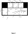
- FIG. 1 shows an embodiment of a base (1) of a drug delivery system according to the present invention.
- the base (1) comprises a plurality of fluid transferring paths i.e. which are inlets (2), a passive mixing chamber (7) having micro pin fins (8) and an outlet (20).
- a chamber into which the fluids to be mixed are introduced are primary chambers (4).
- a primary chamber (4) has at least one inlet (2) portion for introduction of fluids into the primary chamber; and a microchannel (3) for transferring fluids into the passive mixing chamber (7).
- a microchannel (3) preferably comprises a micro-orifice (not shown) for mitigating cavitating flow to enhance mixing.
- Fluid flow directions on the base (1) are basically shown with arrows (6), introduction or injection of fluids into the system through the inlets (2) is basically shown with arrows (16), and fluid mixture outlet (20) from the device is basically shown with arrow (26).
- the base (1) for the drug delivery system according to the present invention is preferably prepared in one piece.
- fluids in a primary chamber (4) can be further transferred through a microchannel (3) into a subsequent chamber (not shown) for further mixing with a fluid transferred from another primary chamber (4).
- Any chamber is preferably monitored in terms of pH by using a sealed pH probe (not shown).
- Wet portions of the base i.e. fluid transferring paths (2, 3) to be subjected to fluids can be heated to obtain preferred temperatures for aimed mixing operations.
- the base (1) comprises at least one passive mixing chamber (7) comprising micro pin fins (8) with heights of 10-100 ⁇ m to enhance passive mixing of fluids by generating turbulence within flowing fluid mixture.
- the turbulence provides an evenly distribution of temperature and concentrations inside the passive mixing chamber (7).
- the micro pin fins (8) also enhance heat transfer to the chamber (4) from a heater (not shown) adjacent with the base (1).
- the heater can preferably be mounted to the lower side of the base (1) which is the opposite side of said upper side.
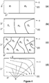
- Figure 2 shows a plan view of the embodiment of Fig.1 , wherein a preferred distribution for the micro pin fins (8) on the base (1) is emphasized. Also a homogeneous distribution of the micro pin fins (8) is possible.
- a machinable material known for the skilled person in the art of microfabrication e.g. silicon, PDMS (polydimethyl siloxane), SU-8, glass, metals and alloys; and preferably silicon, SU8 or PDMS can be selected.
- the base (1) can be fabricated by a microfabrication method such as micromilling, soft lithography, molding, IC (integrated circuit) fabrication methods including lithography, DRIE (deep reactive ion etching), and deposition techniques for keeping the dimensions of the base in micro scale.
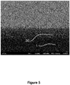
- a nanostructure may be a nano-film (30) as shown in Figure 5 , or a geometrical shape, preferably a nano-rod (40) as shown in Figure 3 integrated on the base, the form of which can be considered as basically cylindrical.
- the distribution of nanostructures varies throughout the base, so that the intensity or distribution of nanostructures is gradual throughout the fluid flow direction.
- the direction, on which the surface tension gradient promotes the fluid flow is basically represented on Figure 1 with arrows (9).
- the nanostructures intensity can be either in its minimum or maximum extent. Whether said intensity in proximinity of the outlet (20) is minimum or maximum, is to be chosen in accordance with production material of the base (1), that of the nanostructures, and the fluids to be mixed in the drug delivery system.
- the base (1) is selectively coated with nanostructures which are made of a material different than the material of said base, such that the base (1) comprises a plurality of regions R 1 to R N with varying nanostructure coating intensities, and such that a surface tension gradient is established among regions R 1 to R N for promoting fluid flow towards the outlet (20).
- Figure 4 (a), (b) and (c) schematically show how the base (1) divides into regions (R 1 to R N ), where 1 ⁇ N and N denotes the number of regions with varying nanostructure coating intensities.
- the intensity of nanostructure coating on a certain region is equal to zero where a unit area (1 ⁇ m 2 ) on said region does not comprise any nanostructure, and equal to 1 where a unit area on said region is fully covered with nanostructures.
- the SEM photograph given in Figure 3 shows a nano-rods (40) coated region with a nanostructure coating intensity of 1
- the representative SEM photograph given in Figure 5 shows a nano-film (30) coated region with a nanostructure coating intensity of 1.
- the nano-film (30) may have a thickness ranging between 50-1500 nm.
- the surface tension gradient promoting the fluid flow towards the outlet (20) is obtained at the liquid-solid interface along the pre-determined fluid flow direction, since the surface tension behavior between liquids and solids in contact with said liquids vary for material choices for nanostructures and base i.e. solid materials. Said minimum intensity may be apprehended as absence of nanostructures in a region on the base, either in proximal or distal regions to the outlet (20).
- GLAD Gancing Angle Deposition
- CVD Chemical Vapor Deposition
- PVD Physical Vapor Deposition
- the base which is at least partly provided with nanostructures of gradual intensity, shape and layout profiles throughout the base can preferably be obtained by GLAD.
- Nano-rods for a base for a drug delivery system have diameters of 50-150 nm and more preferably 75-125 nm; and heights of 500-3000 nm, more preferably 1000-1500 nm for obtaining sufficient fluid guidance effect by adjusting their intensity thus a surface tension gradient throughout the base occurs.
- Figure 3 shows scanning electron microscope (SEM) photographs of the base, wherein the base is provided with basically perpendicular nano-rods as nanostructures; (a) shows the plan view of the base surface, and (b) shows a cross-section thereof.
- the nano-rods can also be inclined with respect to the base surface for obtaining a nanostructure covered base for a drug delivery system according to the present invention.
- the outlet (20) is located in proximity of a distal corner of the base with regard to an inlet (2) as schematically exemplified in Figure 4 (d) .
- the drug delivery system according to the present invention may have reduced pressure.
- Such system comprises a cover (not shown) for protecting the base (1) from outer factors.
- microchannels (3) and chambers (7, 4) define an 'inside' of the drug delivery system; thus the inlets (2) and the outlet (20) remain as mere openings of the drug delivery system connecting the inside of the drug delivery system to the atmosphere.
- the inlets and the outlet are sealed, the system becomes a closed, isolated system.
- the pressure inside the drug delivery system remains reduced compared to the atmospheric pressure until the first use of the drug delivery system. Even though it is not an essential feature of the present invention, reduced pressure inside the system facilitates feeding fluids by causing suction into the system and particularly towards the passive mixing chamber (7).
- the cover is preferably optically transparent so that the fluids in the system and the drug delivery to the patients can be visually spectated. Therefore, the cover is preferably a thin layer made of a transparent solid material e.g. Pyrex, sealed to the base (1).
- a transparent solid material e.g. Pyrex
- the final mixture can be collected from the outlet (20) using an injector (not shown), yet the microfluidic drug delivery system according to the present invention preferably comprises a secondary chamber (not shown) connected with the passive mixing chamber (7) for storing the final fluid mixture upon leaving the passive mixing chamber (7) through the outlet (20).
- the final mixture can be taken through an opening on the secondary chamber, for instance by using an injector.
- the mixing performance of the microfluidic drug delivery system of the above prototype was tested using Bradford reagent (obtained from Sigma Aldrich under the product name B6916) and deionized water, and the absorbance difference results has shown that the mixing performance of the system is found substantial and satisfactory.
- a method for producing a pharmaceutical drug delivery system having a base (1) comprising at least two inlets (2), an outlet (20) and a passive mixing chamber (7) having micro pin fins (8) with heights in the range of 10 to 100 ⁇ m which method comprises the following steps:
- the proposed design and method is promising since it is more compact than commercial pumps in terms of the size and still generates similar flow rates compared to the other micropumps. Furthermore, the design has no moving parts. This kind of actuation could be a significant alternative for more common techniques such as electromechanical, electrokinetic, and piezoelectric actuation and could assist to the flows of reagents due to pressure difference between the inlet and into desired location on the system.
- the heater is preferably controlled by a controller circuit.
- the controller circuit is preferably connected to the casing fed by batteries, preferably located adjacent with the casing, and even more preferably on the lower surface of the base.
- a standard control board such as a pair of Suboard II controller is supplied for the use in a prototype according to the preferred embodiment.
- data provided by temperature sensors and the progress time may preferably be displayed on a display such as an LCD screen of the controller circuit.
- Analog data provided by temperature sensors is converted into digital data by a microcontroller in order to see heating process on the display in the control of heating process.
- the microcontroller is supplied with battery power, and battery power can also be used for supplying a control relay between the heater and the power supply thereof.
- a heater circuit for a drug delivery system may comprise several resistors including bias resistors, a thermistor, a diode and a FET transistor.
- the heater circuit provides required average temperature throughout the microfluidic drug delivery system.
- the heating process is controlled via a microcontroller.
- the heater circuit is connected to the microcontroller and obtains necessary voltage from the controller board.
- a display such as a LED indicator can be added for indication of the temperature within the device.
- the change in the bias resistors can be applied to obtain a set point as a higher limit for the temperature.
- Solid state temperature sensors are suitable for the system. Such sensors enable temperature measurements between -55 and 150°C for control applications.
- a temperature sensor can be used for determining minimum, average, and differential temperatures.
- Temperature sensors for the device convert temperature input into proportional current output so that one can see the actual temperature level and even control it by connecting the temperature sensor to the microcontroller.
- at least one of such sensors is integrated with the device. Temperature values due to the heat supplied by the heater are to be measured by these temperature sensors.
- the packaging material should be thermally conductive e.g. a metal or alloy thereof for facilitating the heat transfer from the outside of the packaging. Obviously, the melting point of the packaging material should be higher than the temperatures provided by the heater.
- CAD computer-aided design
- the present invention enables mobility in a practical and economical manner due to its size and disposable coverage.
- the drug delivery process is highly safe due to control of the quantity of reagents and the heating operation.
- the drug delivery system of the present invention which is a micro electro mechanical system (MEMS) further provides an improved device featuring homogenous mixing process of multiple reagents, heating process, and controllability. Conveying of reagents is independent of any external device and independent of power source. This group of objects is achieved by means of surface tension gradients on the base in consequence of non-homogenous distribution of nanostructures, and reduced pressure within the device. Effective heating as a result of enhanced surface area with pin fins promoting turbulation thus mixing provides significant advantages over microfluidic drug delivery systems of the prior art.
- MEMS micro electro mechanical system
- the present invention brings passive conveying, effective mixing, heating and controlling all the processes together in one device. Further, it does not require any external power source and is relatively cheap in comparison with alternative drug delivery systems such as transdermal ones. Homogenous mixing of the reagents is achieved in an improved manner.
- the drug delivery system of the present invention exploits Micro Electro Mechanical System (MEMS) technology to address to the requirement for an autonomous, effective, and compact drug delivery system.
- MEMS Micro Electro Mechanical System
Claims (15)
- Pharmazeutisches Wirkstoffabgabesystem mit einer Basis (1), die mindestens zwei Einlässe (2), einen Auslass (20) und eine passive Mischkammer (7) mit Mikropin-Rippen (8) mit Höhen im Bereich von 10 bis 100 µm, dadurch gekennzeichnet, dass die Basis (1) selektiv mit Nanostrukturen beschichtet ist, die aus einem vom Material der Basis verschiedenen Material gemacht sind, so dass die Basis (1) eine Vielzahl an Regionen R1 bis RN umfasst, von denen jede eine verschiedene Nanostrukturbeschichtungsintensität aufweist, und so dass ein Oberflächenspannungsgradient zwischen Regionen R1 bis RN zum Fördern von Flüssigkeitsfluss auf den Auslass (20) hin aufgebaut ist.
- Pharmazeutisches Wirkstoffabgabesystem nach Anspruch 1, wobei die Basis (1) weiterhin eine primäre Kammer (4) umfasst, die einen oder mehrere Mikrokanal/Mikrokanäle (3) zum Überführen von Flüssigkeit in eine anschließende Kammer aufweist.
- Pharmazeutisches Wirkstoffabgabesystem nach Anspruch 2, wobei die anschließende Kammer die passive Mischkammer (7) ist.
- Pharmazeutisches Wirkstoffabgabesystem nach Anspruch 2 oder Anspruch 3, wobei der eine oder die mehreren Mikrokanäle (3) eine Mikroöffnung zum Abschwächen von kavitierendem Durchfluss umfasst, um Mischen zu verstärken.
- Pharmazeutisches Wirkstoffabgabesystem nach Anspruch 1, wobei die Basis (1) aus einem Material ausgewählt aus der Liste bestehend aus Silizium, Polydimethylsiloxan, SU-8, Glas, Metallen und Metalllegierungen gemacht ist.
- Pharmazeutisches Wirkstoffabgabesystem nach Anspruch 1, wobei die Nanostruktur aus einem Material ausgewählt aus der Liste bestehend aus Silizium, Polydimethylsiloxan, SU-8, Glas, Metallen und Metalllegierungen gemacht ist.
- Pharmazeutisches Wirkstoffabgabesystem nach Anspruch 1, wobei die Nanostrukturen Nanostäbchen mit Durchmessern im Bereich von 50 bis 150 nm und Höhen im Bereich von 500 bis 3000 nm sind.
- Pharmazeutisches Wirkstoffabgabesystem nach Anspruch 1, wobei die Nanostrukturen Nanostäbchen mit Durchmessern von 75-125 nm und Höhen von 1000-1500 nm sind.
- Pharmazeutisches Wirkstoffabgabesystem nach Anspruch 1, wobei die Nanostruktur ein Nanofilm mit einer Dicke im Bereich von 50-1500 nm ist.
- Pharmazeutisches Wirkstoffabgabesystem nach Anspruch 1, wobei das Wirkstoffabgabesystem eine sekundäre Kammer umfasst, die mit der passiven Mischkammer (7) zum Lagern von Flüssigkeit beim Verlassen der passiven Mischkammer (7) durch den Auslass (20) verbunden ist.
- Pharmazeutisches Wirkstoffabgabesystem nach Anspruch 10, wobei das System weiterhin eine Abdeckung umfasst, die aus einem optisch transparenten Material gemacht ist.
- Verfahren zum Herstellen eines pharmazeutischen Wirkstoffabgabesystems gemäß Anspruch 1, mit einer Basis (1), mindestens zwei Einlässen (2), einem Auslass (20) und einer passiven Mischkammer (7) mit Mikropin-Rippen (8) mit Höhen im Bereich von 10 bis 100 µm; wobei das Verfahren die Schritte umfasst:a- Bilden einer Basis (1), die mindestens zwei Einlässe (2), einen Auslass (20) und eine passive Mischkammer (7) mit Mikropin-Rippen (8) mit Höhen im Bereich von 10 bis 100 µm umfasst;b- selektives Beschichten der Basis mit Nanostrukturen, die aus einem Material gemacht sind, das verschieden vom Material der Basis ist, so dass die Basis (1) eine Vielzahl an Regionen R1 bis RN umfasst, von denen jede eine verschiedene Nanostrukturbeschichtungsintensität aufweist, und so dass ein Oberflächenspannungsgradient zwischen Regionen R1 bis RN zum Fördern von Flüssigkeitsfluss auf den Auslass (20) hin aufgebaut ist.
- Verfahren nach Anspruch 11, wobei die Basis unter Verwendung einer Mikrofabrikationstechnik gebildet wird, die aus der Liste ausgewählt ist, die aus Mikromahlen, weicher Lithographie, Formen, Lithographie, reaktivem Ionentiefätzen und Abscheidungstechniken besteht.
- Verfahren nach Anspruch 11, wobei die Nanostrukturbeschichtung entweder durch Glanzwinkel-Abscheidung, chemische Dampfabscheidung oder physikalische Dampfabscheidung gebildet wird.
- Verfahren nach Anspruch 11, wobei das Verfahren weiterhin den Schritt des Isolierens des Wirkstoffabgabesystems und Anlegen von Vakuum innerhalb der passiven Mischkammer (7) umfasst.
Priority Applications (3)
| Application Number | Priority Date | Filing Date | Title |
|---|---|---|---|
| EP14159546.2A EP2918263B1 (de) | 2014-03-13 | 2014-03-13 | Arzneimittelabgabesystem |
| PCT/EP2015/055168 WO2015136036A1 (en) | 2014-03-13 | 2015-03-12 | Pharmaceutical drug delivery system |
| US15/123,654 US10166330B2 (en) | 2014-03-13 | 2015-03-12 | Pharmaceutical drug delivery system |
Applications Claiming Priority (1)
| Application Number | Priority Date | Filing Date | Title |
|---|---|---|---|
| EP14159546.2A EP2918263B1 (de) | 2014-03-13 | 2014-03-13 | Arzneimittelabgabesystem |
Publications (2)
| Publication Number | Publication Date |
|---|---|
| EP2918263A1 EP2918263A1 (de) | 2015-09-16 |
| EP2918263B1 true EP2918263B1 (de) | 2017-05-03 |
Family
ID=50423965
Family Applications (1)
| Application Number | Title | Priority Date | Filing Date |
|---|---|---|---|
| EP14159546.2A Active EP2918263B1 (de) | 2014-03-13 | 2014-03-13 | Arzneimittelabgabesystem |
Country Status (3)
| Country | Link |
|---|---|
| US (1) | US10166330B2 (de) |
| EP (1) | EP2918263B1 (de) |
| WO (1) | WO2015136036A1 (de) |
Families Citing this family (1)
| Publication number | Priority date | Publication date | Assignee | Title |
|---|---|---|---|---|
| US11766822B2 (en) | 2019-08-20 | 2023-09-26 | 3M Innovative Properties Company | Microstructured surface with increased microorganism removal when cleaned, articles and methods |
Family Cites Families (13)
| Publication number | Priority date | Publication date | Assignee | Title |
|---|---|---|---|---|
| US6283294B1 (en) * | 1999-09-01 | 2001-09-04 | Biogaia Biologics Ab | Enclosed living cell dispensing tube |
| US6589229B1 (en) | 2000-07-31 | 2003-07-08 | Becton, Dickinson And Company | Wearable, self-contained drug infusion device |
| ATE420681T1 (de) | 2001-09-26 | 2009-01-15 | Novo Nordisk As | Modulare vorrichtung zur verabreichung von medikamenten |
| SE0201738D0 (sv) * | 2002-06-07 | 2002-06-07 | Aamic Ab | Micro-fluid structures |
| EP1539270A1 (de) * | 2002-09-18 | 2005-06-15 | Medtronic Vascular, Inc. | Steuerbare, arznemittelfreisetzende gradientbeschichtungen für medizinische vorrichtungen |
| US20070100306A1 (en) * | 2005-11-03 | 2007-05-03 | Dizio James P | Release coating containing thermoplastic polymers |
| US20080045925A1 (en) | 2006-06-19 | 2008-02-21 | Stepovich Matthew J | Drug delivery system |
| US8186913B2 (en) * | 2007-04-16 | 2012-05-29 | The General Hospital Corporation | Systems and methods for particle focusing in microchannels |
| EP2406007A4 (de) * | 2009-03-10 | 2013-03-06 | Univ Monash | Thrombozytenaggregation anhand einer mikrofluidischen vorrichtung |
| KR100974626B1 (ko) * | 2009-12-22 | 2010-08-09 | 동국대학교 산학협력단 | 접촉 구조의 나노로드 반도체 소자 및 그 제조 방법 |
| WO2011102892A1 (en) * | 2010-02-18 | 2011-08-25 | Kent State University | Fast-switching surface-stabilized liquid crystal cells |
| EP2632613B1 (de) * | 2010-10-28 | 2017-08-30 | 3M Innovative Properties Company | Manipulierte oberflächen zur reduktion der bakteriellen adhäsion |
| US8696637B2 (en) * | 2011-02-28 | 2014-04-15 | Kimberly-Clark Worldwide | Transdermal patch containing microneedles |
-
2014
- 2014-03-13 EP EP14159546.2A patent/EP2918263B1/de active Active
-
2015
- 2015-03-12 US US15/123,654 patent/US10166330B2/en active Active
- 2015-03-12 WO PCT/EP2015/055168 patent/WO2015136036A1/en active Application Filing
Also Published As
| Publication number | Publication date |
|---|---|
| US10166330B2 (en) | 2019-01-01 |
| EP2918263A1 (de) | 2015-09-16 |
| US20170072138A1 (en) | 2017-03-16 |
| WO2015136036A1 (en) | 2015-09-17 |
Similar Documents
| Publication | Publication Date | Title |
|---|---|---|
| CN103328089B (zh) | 喷雾干燥技术 | |
| AU2003270320B2 (en) | Aerosol generating device and method of use thereof | |
| CN100482352C (zh) | 气溶胶产生装置和方法 | |
| KR100799611B1 (ko) | 에어로졸 발생기 및, 에어로졸 발생기를 제조하고사용하는 방법 | |
| CN101356378B (zh) | 微流体系统 | |
| KR20180118119A (ko) | 전자담배제품 및 전자담배제품용 카트리지 | |
| Roy et al. | Microelectromechanical systems and neurosurgery: A new era in a new millennium | |
| US7740619B2 (en) | Spring driven ophthalmic injection device with safety actuator lockout feature | |
| JP2001505640A (ja) | マイクロポンプ | |
| TW200800403A (en) | Swirl nozzle | |
| WO2007095296A2 (en) | Fluid delivery apparatus with vial fill | |
| WO2016085739A1 (en) | Systems and methods for encapsulation of actives in compartments or sub-compartments | |
| US10166330B2 (en) | Pharmaceutical drug delivery system | |
| TW200301709A (en) | Infusion system | |
| Li et al. | Perturbation-induced droplets for manipulating droplet structure and configuration in microfluidics | |
| US6854460B1 (en) | Controlled deliveries and depositions of pharmaceutical and other aerosolized masses | |
| Hwang et al. | Targeted electrohydrodynamic printing for micro-reservoir drug delivery systems | |
| JP7299900B2 (ja) | 流体投与アセンブリ | |
| Hosseini | Micro-electromechanical system based electronic capsules (MEMS) aimed at optimizing drug delivery to the human body | |
| US20220280731A1 (en) | Aerosol delivery devices and methods of using same | |
| Lopez-Salazar et al. | Design and simulation of a high precision drug delivery system | |
| TW201622766A (zh) | 流體施配裝置及其製造方法 | |
| Lee | Drug delivery microdevice: Design, simulation, and experiments | |
| US20220295896A1 (en) | Aerosol delivery devices and methods of using same | |
| Last et al. | Scaling toward Diminutive MEMS: Dust‐Sized Spray Chips for Aerosolized Drug Delivery to the Lung |
Legal Events
| Date | Code | Title | Description |
|---|---|---|---|
| PUAI | Public reference made under article 153(3) epc to a published international application that has entered the european phase |
Free format text: ORIGINAL CODE: 0009012 |
|
| AK | Designated contracting states |
Kind code of ref document: A1 Designated state(s): AL AT BE BG CH CY CZ DE DK EE ES FI FR GB GR HR HU IE IS IT LI LT LU LV MC MK MT NL NO PL PT RO RS SE SI SK SM TR |
|
| AX | Request for extension of the european patent |
Extension state: BA ME |
|
| 17P | Request for examination filed |
Effective date: 20160210 |
|
| RBV | Designated contracting states (corrected) |
Designated state(s): AL AT BE BG CH CY CZ DE DK EE ES FI FR GB GR HR HU IE IS IT LI LT LU LV MC MK MT NL NO PL PT RO RS SE SI SK SM TR |
|
| REG | Reference to a national code |
Ref country code: DE Ref legal event code: R079 Ref document number: 602014009195 Country of ref document: DE Free format text: PREVIOUS MAIN CLASS: A61K0009000000 Ipc: A61M0005142000 |
|
| GRAP | Despatch of communication of intention to grant a patent |
Free format text: ORIGINAL CODE: EPIDOSNIGR1 |
|
| RIC1 | Information provided on ipc code assigned before grant |
Ipc: A61M 5/142 20060101AFI20161025BHEP |
|
| INTG | Intention to grant announced |
Effective date: 20161124 |
|
| RIN1 | Information on inventor provided before grant (corrected) |
Inventor name: KOSAR, ALI Inventor name: PERK, OSMAN YAVUZ |
|
| GRAS | Grant fee paid |
Free format text: ORIGINAL CODE: EPIDOSNIGR3 |
|
| GRAA | (expected) grant |
Free format text: ORIGINAL CODE: 0009210 |
|
| AK | Designated contracting states |
Kind code of ref document: B1 Designated state(s): AL AT BE BG CH CY CZ DE DK EE ES FI FR GB GR HR HU IE IS IT LI LT LU LV MC MK MT NL NO PL PT RO RS SE SI SK SM TR |
|
| REG | Reference to a national code |
Ref country code: GB Ref legal event code: FG4D |
|
| REG | Reference to a national code |
Ref country code: AT Ref legal event code: REF Ref document number: 889266 Country of ref document: AT Kind code of ref document: T Effective date: 20170515 Ref country code: CH Ref legal event code: EP |
|
| REG | Reference to a national code |
Ref country code: IE Ref legal event code: FG4D |
|
| REG | Reference to a national code |
Ref country code: DE Ref legal event code: R096 Ref document number: 602014009195 Country of ref document: DE |
|
| REG | Reference to a national code |
Ref country code: NL Ref legal event code: MP Effective date: 20170503 |
|
| REG | Reference to a national code |
Ref country code: AT Ref legal event code: MK05 Ref document number: 889266 Country of ref document: AT Kind code of ref document: T Effective date: 20170503 |
|
| REG | Reference to a national code |
Ref country code: LT Ref legal event code: MG4D |
|
| PG25 | Lapsed in a contracting state [announced via postgrant information from national office to epo] |
Ref country code: HR Free format text: LAPSE BECAUSE OF FAILURE TO SUBMIT A TRANSLATION OF THE DESCRIPTION OR TO PAY THE FEE WITHIN THE PRESCRIBED TIME-LIMIT Effective date: 20170503 Ref country code: NO Free format text: LAPSE BECAUSE OF FAILURE TO SUBMIT A TRANSLATION OF THE DESCRIPTION OR TO PAY THE FEE WITHIN THE PRESCRIBED TIME-LIMIT Effective date: 20170803 Ref country code: LT Free format text: LAPSE BECAUSE OF FAILURE TO SUBMIT A TRANSLATION OF THE DESCRIPTION OR TO PAY THE FEE WITHIN THE PRESCRIBED TIME-LIMIT Effective date: 20170503 Ref country code: ES Free format text: LAPSE BECAUSE OF FAILURE TO SUBMIT A TRANSLATION OF THE DESCRIPTION OR TO PAY THE FEE WITHIN THE PRESCRIBED TIME-LIMIT Effective date: 20170503 Ref country code: AT Free format text: LAPSE BECAUSE OF FAILURE TO SUBMIT A TRANSLATION OF THE DESCRIPTION OR TO PAY THE FEE WITHIN THE PRESCRIBED TIME-LIMIT Effective date: 20170503 Ref country code: GR Free format text: LAPSE BECAUSE OF FAILURE TO SUBMIT A TRANSLATION OF THE DESCRIPTION OR TO PAY THE FEE WITHIN THE PRESCRIBED TIME-LIMIT Effective date: 20170804 Ref country code: FI Free format text: LAPSE BECAUSE OF FAILURE TO SUBMIT A TRANSLATION OF THE DESCRIPTION OR TO PAY THE FEE WITHIN THE PRESCRIBED TIME-LIMIT Effective date: 20170503 |
|
| PG25 | Lapsed in a contracting state [announced via postgrant information from national office to epo] |
Ref country code: PL Free format text: LAPSE BECAUSE OF FAILURE TO SUBMIT A TRANSLATION OF THE DESCRIPTION OR TO PAY THE FEE WITHIN THE PRESCRIBED TIME-LIMIT Effective date: 20170503 Ref country code: IS Free format text: LAPSE BECAUSE OF FAILURE TO SUBMIT A TRANSLATION OF THE DESCRIPTION OR TO PAY THE FEE WITHIN THE PRESCRIBED TIME-LIMIT Effective date: 20170903 Ref country code: NL Free format text: LAPSE BECAUSE OF FAILURE TO SUBMIT A TRANSLATION OF THE DESCRIPTION OR TO PAY THE FEE WITHIN THE PRESCRIBED TIME-LIMIT Effective date: 20170503 Ref country code: BG Free format text: LAPSE BECAUSE OF FAILURE TO SUBMIT A TRANSLATION OF THE DESCRIPTION OR TO PAY THE FEE WITHIN THE PRESCRIBED TIME-LIMIT Effective date: 20170803 Ref country code: LV Free format text: LAPSE BECAUSE OF FAILURE TO SUBMIT A TRANSLATION OF THE DESCRIPTION OR TO PAY THE FEE WITHIN THE PRESCRIBED TIME-LIMIT Effective date: 20170503 Ref country code: SE Free format text: LAPSE BECAUSE OF FAILURE TO SUBMIT A TRANSLATION OF THE DESCRIPTION OR TO PAY THE FEE WITHIN THE PRESCRIBED TIME-LIMIT Effective date: 20170503 Ref country code: RS Free format text: LAPSE BECAUSE OF FAILURE TO SUBMIT A TRANSLATION OF THE DESCRIPTION OR TO PAY THE FEE WITHIN THE PRESCRIBED TIME-LIMIT Effective date: 20170503 |
|
| PG25 | Lapsed in a contracting state [announced via postgrant information from national office to epo] |
Ref country code: RO Free format text: LAPSE BECAUSE OF FAILURE TO SUBMIT A TRANSLATION OF THE DESCRIPTION OR TO PAY THE FEE WITHIN THE PRESCRIBED TIME-LIMIT Effective date: 20170503 Ref country code: DK Free format text: LAPSE BECAUSE OF FAILURE TO SUBMIT A TRANSLATION OF THE DESCRIPTION OR TO PAY THE FEE WITHIN THE PRESCRIBED TIME-LIMIT Effective date: 20170503 Ref country code: CZ Free format text: LAPSE BECAUSE OF FAILURE TO SUBMIT A TRANSLATION OF THE DESCRIPTION OR TO PAY THE FEE WITHIN THE PRESCRIBED TIME-LIMIT Effective date: 20170503 Ref country code: SK Free format text: LAPSE BECAUSE OF FAILURE TO SUBMIT A TRANSLATION OF THE DESCRIPTION OR TO PAY THE FEE WITHIN THE PRESCRIBED TIME-LIMIT Effective date: 20170503 Ref country code: EE Free format text: LAPSE BECAUSE OF FAILURE TO SUBMIT A TRANSLATION OF THE DESCRIPTION OR TO PAY THE FEE WITHIN THE PRESCRIBED TIME-LIMIT Effective date: 20170503 |
|
| REG | Reference to a national code |
Ref country code: DE Ref legal event code: R097 Ref document number: 602014009195 Country of ref document: DE |
|
| PG25 | Lapsed in a contracting state [announced via postgrant information from national office to epo] |
Ref country code: IT Free format text: LAPSE BECAUSE OF FAILURE TO SUBMIT A TRANSLATION OF THE DESCRIPTION OR TO PAY THE FEE WITHIN THE PRESCRIBED TIME-LIMIT Effective date: 20170503 Ref country code: SM Free format text: LAPSE BECAUSE OF FAILURE TO SUBMIT A TRANSLATION OF THE DESCRIPTION OR TO PAY THE FEE WITHIN THE PRESCRIBED TIME-LIMIT Effective date: 20170503 |
|
| PLBE | No opposition filed within time limit |
Free format text: ORIGINAL CODE: 0009261 |
|
| STAA | Information on the status of an ep patent application or granted ep patent |
Free format text: STATUS: NO OPPOSITION FILED WITHIN TIME LIMIT |
|
| 26N | No opposition filed |
Effective date: 20180206 |
|
| PG25 | Lapsed in a contracting state [announced via postgrant information from national office to epo] |
Ref country code: SI Free format text: LAPSE BECAUSE OF FAILURE TO SUBMIT A TRANSLATION OF THE DESCRIPTION OR TO PAY THE FEE WITHIN THE PRESCRIBED TIME-LIMIT Effective date: 20170503 |
|
| REG | Reference to a national code |
Ref country code: CH Ref legal event code: PL |
|
| PG25 | Lapsed in a contracting state [announced via postgrant information from national office to epo] |
Ref country code: MC Free format text: LAPSE BECAUSE OF FAILURE TO SUBMIT A TRANSLATION OF THE DESCRIPTION OR TO PAY THE FEE WITHIN THE PRESCRIBED TIME-LIMIT Effective date: 20170503 |
|
| REG | Reference to a national code |
Ref country code: BE Ref legal event code: MM Effective date: 20180331 |
|
| REG | Reference to a national code |
Ref country code: IE Ref legal event code: MM4A |
|
| PG25 | Lapsed in a contracting state [announced via postgrant information from national office to epo] |
Ref country code: LU Free format text: LAPSE BECAUSE OF NON-PAYMENT OF DUE FEES Effective date: 20180313 |
|
| PG25 | Lapsed in a contracting state [announced via postgrant information from national office to epo] |
Ref country code: IE Free format text: LAPSE BECAUSE OF NON-PAYMENT OF DUE FEES Effective date: 20180313 |
|
| PG25 | Lapsed in a contracting state [announced via postgrant information from national office to epo] |
Ref country code: CH Free format text: LAPSE BECAUSE OF NON-PAYMENT OF DUE FEES Effective date: 20180331 Ref country code: BE Free format text: LAPSE BECAUSE OF NON-PAYMENT OF DUE FEES Effective date: 20180331 Ref country code: LI Free format text: LAPSE BECAUSE OF NON-PAYMENT OF DUE FEES Effective date: 20180331 |
|
| PG25 | Lapsed in a contracting state [announced via postgrant information from national office to epo] |
Ref country code: FR Free format text: LAPSE BECAUSE OF NON-PAYMENT OF DUE FEES Effective date: 20180331 |
|
| PG25 | Lapsed in a contracting state [announced via postgrant information from national office to epo] |
Ref country code: MT Free format text: LAPSE BECAUSE OF NON-PAYMENT OF DUE FEES Effective date: 20180313 |
|
| PG25 | Lapsed in a contracting state [announced via postgrant information from national office to epo] |
Ref country code: TR Free format text: LAPSE BECAUSE OF FAILURE TO SUBMIT A TRANSLATION OF THE DESCRIPTION OR TO PAY THE FEE WITHIN THE PRESCRIBED TIME-LIMIT Effective date: 20170503 |
|
| PG25 | Lapsed in a contracting state [announced via postgrant information from national office to epo] |
Ref country code: PT Free format text: LAPSE BECAUSE OF FAILURE TO SUBMIT A TRANSLATION OF THE DESCRIPTION OR TO PAY THE FEE WITHIN THE PRESCRIBED TIME-LIMIT Effective date: 20170503 |
|
| PG25 | Lapsed in a contracting state [announced via postgrant information from national office to epo] |
Ref country code: CY Free format text: LAPSE BECAUSE OF FAILURE TO SUBMIT A TRANSLATION OF THE DESCRIPTION OR TO PAY THE FEE WITHIN THE PRESCRIBED TIME-LIMIT Effective date: 20170503 Ref country code: HU Free format text: LAPSE BECAUSE OF FAILURE TO SUBMIT A TRANSLATION OF THE DESCRIPTION OR TO PAY THE FEE WITHIN THE PRESCRIBED TIME-LIMIT; INVALID AB INITIO Effective date: 20140313 Ref country code: MK Free format text: LAPSE BECAUSE OF NON-PAYMENT OF DUE FEES Effective date: 20170503 |
|
| PG25 | Lapsed in a contracting state [announced via postgrant information from national office to epo] |
Ref country code: AL Free format text: LAPSE BECAUSE OF FAILURE TO SUBMIT A TRANSLATION OF THE DESCRIPTION OR TO PAY THE FEE WITHIN THE PRESCRIBED TIME-LIMIT Effective date: 20170503 |
|
| PGFP | Annual fee paid to national office [announced via postgrant information from national office to epo] |
Ref country code: GB Payment date: 20230324 Year of fee payment: 10 Ref country code: DE Payment date: 20230307 Year of fee payment: 10 |