US9795747B2 - Methods and apparatus for lancet actuation - Google Patents
Methods and apparatus for lancet actuation Download PDFInfo
- Publication number
- US9795747B2 US9795747B2 US13/151,613 US201113151613A US9795747B2 US 9795747 B2 US9795747 B2 US 9795747B2 US 201113151613 A US201113151613 A US 201113151613A US 9795747 B2 US9795747 B2 US 9795747B2
- Authority
- US
- United States
- Prior art keywords
- lancet
- sample
- driver
- sampling
- skin
- Prior art date
- Legal status (The legal status is an assumption and is not a legal conclusion. Google has not performed a legal analysis and makes no representation as to the accuracy of the status listed.)
- Active
Links
Images


Classifications
-
- A—HUMAN NECESSITIES
- A61—MEDICAL OR VETERINARY SCIENCE; HYGIENE
- A61M—DEVICES FOR INTRODUCING MEDIA INTO, OR ONTO, THE BODY; DEVICES FOR TRANSDUCING BODY MEDIA OR FOR TAKING MEDIA FROM THE BODY; DEVICES FOR PRODUCING OR ENDING SLEEP OR STUPOR
- A61M5/00—Devices for bringing media into the body in a subcutaneous, intra-vascular or intramuscular way; Accessories therefor, e.g. filling or cleaning devices, arm-rests
- A61M5/46—Devices for bringing media into the body in a subcutaneous, intra-vascular or intramuscular way; Accessories therefor, e.g. filling or cleaning devices, arm-rests having means for controlling depth of insertion
-
- A—HUMAN NECESSITIES
- A61—MEDICAL OR VETERINARY SCIENCE; HYGIENE
- A61B—DIAGNOSIS; SURGERY; IDENTIFICATION
- A61B5/00—Measuring for diagnostic purposes; Identification of persons
- A61B5/15—Devices for taking samples of blood
- A61B5/150007—Details
- A61B5/150015—Source of blood
- A61B5/150022—Source of blood for capillary blood or interstitial fluid
-
- A—HUMAN NECESSITIES
- A61—MEDICAL OR VETERINARY SCIENCE; HYGIENE
- A61B—DIAGNOSIS; SURGERY; IDENTIFICATION
- A61B5/00—Measuring for diagnostic purposes; Identification of persons
- A61B5/15—Devices for taking samples of blood
- A61B5/150007—Details
- A61B5/150053—Details for enhanced collection of blood or interstitial fluid at the sample site, e.g. by applying compression, heat, vibration, ultrasound, suction or vacuum to tissue; for reduction of pain or discomfort; Skin piercing elements, e.g. blades, needles, lancets or canulas, with adjustable piercing speed
- A61B5/150061—Means for enhancing collection
- A61B5/150083—Means for enhancing collection by vibration, e.g. ultrasound
-
- A—HUMAN NECESSITIES
- A61—MEDICAL OR VETERINARY SCIENCE; HYGIENE
- A61B—DIAGNOSIS; SURGERY; IDENTIFICATION
- A61B5/00—Measuring for diagnostic purposes; Identification of persons
- A61B5/15—Devices for taking samples of blood
- A61B5/150007—Details
- A61B5/150053—Details for enhanced collection of blood or interstitial fluid at the sample site, e.g. by applying compression, heat, vibration, ultrasound, suction or vacuum to tissue; for reduction of pain or discomfort; Skin piercing elements, e.g. blades, needles, lancets or canulas, with adjustable piercing speed
- A61B5/150061—Means for enhancing collection
- A61B5/150091—Means for enhancing collection by electricity
-
- A—HUMAN NECESSITIES
- A61—MEDICAL OR VETERINARY SCIENCE; HYGIENE
- A61B—DIAGNOSIS; SURGERY; IDENTIFICATION
- A61B5/00—Measuring for diagnostic purposes; Identification of persons
- A61B5/15—Devices for taking samples of blood
- A61B5/150007—Details
- A61B5/150053—Details for enhanced collection of blood or interstitial fluid at the sample site, e.g. by applying compression, heat, vibration, ultrasound, suction or vacuum to tissue; for reduction of pain or discomfort; Skin piercing elements, e.g. blades, needles, lancets or canulas, with adjustable piercing speed
- A61B5/150061—Means for enhancing collection
- A61B5/150099—Means for enhancing collection by negative pressure, other than vacuum extraction into a syringe by pulling on the piston rod or into pre-evacuated tubes
-
- A—HUMAN NECESSITIES
- A61—MEDICAL OR VETERINARY SCIENCE; HYGIENE
- A61B—DIAGNOSIS; SURGERY; IDENTIFICATION
- A61B5/00—Measuring for diagnostic purposes; Identification of persons
- A61B5/15—Devices for taking samples of blood
- A61B5/150007—Details
- A61B5/150053—Details for enhanced collection of blood or interstitial fluid at the sample site, e.g. by applying compression, heat, vibration, ultrasound, suction or vacuum to tissue; for reduction of pain or discomfort; Skin piercing elements, e.g. blades, needles, lancets or canulas, with adjustable piercing speed
- A61B5/150106—Means for reducing pain or discomfort applied before puncturing; desensitising the skin at the location where body is to be pierced
- A61B5/150137—Means for reducing pain or discomfort applied before puncturing; desensitising the skin at the location where body is to be pierced by vibration
-
- A—HUMAN NECESSITIES
- A61—MEDICAL OR VETERINARY SCIENCE; HYGIENE
- A61B—DIAGNOSIS; SURGERY; IDENTIFICATION
- A61B5/00—Measuring for diagnostic purposes; Identification of persons
- A61B5/15—Devices for taking samples of blood
- A61B5/150007—Details
- A61B5/150053—Details for enhanced collection of blood or interstitial fluid at the sample site, e.g. by applying compression, heat, vibration, ultrasound, suction or vacuum to tissue; for reduction of pain or discomfort; Skin piercing elements, e.g. blades, needles, lancets or canulas, with adjustable piercing speed
- A61B5/150106—Means for reducing pain or discomfort applied before puncturing; desensitising the skin at the location where body is to be pierced
- A61B5/150152—Means for reducing pain or discomfort applied before puncturing; desensitising the skin at the location where body is to be pierced by an adequate mechanical impact on the puncturing location
-
- A—HUMAN NECESSITIES
- A61—MEDICAL OR VETERINARY SCIENCE; HYGIENE
- A61B—DIAGNOSIS; SURGERY; IDENTIFICATION
- A61B5/00—Measuring for diagnostic purposes; Identification of persons
- A61B5/15—Devices for taking samples of blood
- A61B5/150007—Details
- A61B5/150053—Details for enhanced collection of blood or interstitial fluid at the sample site, e.g. by applying compression, heat, vibration, ultrasound, suction or vacuum to tissue; for reduction of pain or discomfort; Skin piercing elements, e.g. blades, needles, lancets or canulas, with adjustable piercing speed
- A61B5/150167—Adjustable piercing speed of skin piercing element, e.g. blade, needle, lancet or canula, for example with varying spring force or pneumatic drive
-
- A—HUMAN NECESSITIES
- A61—MEDICAL OR VETERINARY SCIENCE; HYGIENE
- A61B—DIAGNOSIS; SURGERY; IDENTIFICATION
- A61B5/00—Measuring for diagnostic purposes; Identification of persons
- A61B5/15—Devices for taking samples of blood
- A61B5/150007—Details
- A61B5/150175—Adjustment of penetration depth
- A61B5/15019—Depth adjustment mechanism using movable stops located inside the piercing device housing and limiting the travel of the drive mechanism
-
- A—HUMAN NECESSITIES
- A61—MEDICAL OR VETERINARY SCIENCE; HYGIENE
- A61B—DIAGNOSIS; SURGERY; IDENTIFICATION
- A61B5/00—Measuring for diagnostic purposes; Identification of persons
- A61B5/15—Devices for taking samples of blood
- A61B5/150007—Details
- A61B5/150206—Construction or design features not otherwise provided for; manufacturing or production; packages; sterilisation of piercing element, piercing device or sampling device
- A61B5/150267—Modular design or construction, i.e. subunits are assembled separately before being joined together or the device comprises interchangeable or detachable modules
-
- A—HUMAN NECESSITIES
- A61—MEDICAL OR VETERINARY SCIENCE; HYGIENE
- A61B—DIAGNOSIS; SURGERY; IDENTIFICATION
- A61B5/00—Measuring for diagnostic purposes; Identification of persons
- A61B5/15—Devices for taking samples of blood
- A61B5/150007—Details
- A61B5/150206—Construction or design features not otherwise provided for; manufacturing or production; packages; sterilisation of piercing element, piercing device or sampling device
- A61B5/150274—Manufacture or production processes or steps for blood sampling devices
- A61B5/150282—Manufacture or production processes or steps for blood sampling devices for piercing elements, e.g. blade, lancet, canula, needle
-
- A—HUMAN NECESSITIES
- A61—MEDICAL OR VETERINARY SCIENCE; HYGIENE
- A61B—DIAGNOSIS; SURGERY; IDENTIFICATION
- A61B5/00—Measuring for diagnostic purposes; Identification of persons
- A61B5/15—Devices for taking samples of blood
- A61B5/150007—Details
- A61B5/150206—Construction or design features not otherwise provided for; manufacturing or production; packages; sterilisation of piercing element, piercing device or sampling device
- A61B5/150274—Manufacture or production processes or steps for blood sampling devices
- A61B5/15029—Manufacture or production processes or steps for blood sampling devices for driving devices, i.e. means for driving the piercing element
-
- A—HUMAN NECESSITIES
- A61—MEDICAL OR VETERINARY SCIENCE; HYGIENE
- A61B—DIAGNOSIS; SURGERY; IDENTIFICATION
- A61B5/00—Measuring for diagnostic purposes; Identification of persons
- A61B5/15—Devices for taking samples of blood
- A61B5/150007—Details
- A61B5/150374—Details of piercing elements or protective means for preventing accidental injuries by such piercing elements
- A61B5/150381—Design of piercing elements
- A61B5/150412—Pointed piercing elements, e.g. needles, lancets for piercing the skin
- A61B5/150427—Specific tip design, e.g. for improved penetration characteristics
-
- A—HUMAN NECESSITIES
- A61—MEDICAL OR VETERINARY SCIENCE; HYGIENE
- A61B—DIAGNOSIS; SURGERY; IDENTIFICATION
- A61B5/00—Measuring for diagnostic purposes; Identification of persons
- A61B5/15—Devices for taking samples of blood
- A61B5/150007—Details
- A61B5/150374—Details of piercing elements or protective means for preventing accidental injuries by such piercing elements
- A61B5/150534—Design of protective means for piercing elements for preventing accidental needle sticks, e.g. shields, caps, protectors, axially extensible sleeves, pivotable protective sleeves
- A61B5/150572—Pierceable protectors, e.g. shields, caps, sleeves or films, e.g. for hygienic purposes
-
- A—HUMAN NECESSITIES
- A61—MEDICAL OR VETERINARY SCIENCE; HYGIENE
- A61B—DIAGNOSIS; SURGERY; IDENTIFICATION
- A61B5/00—Measuring for diagnostic purposes; Identification of persons
- A61B5/15—Devices for taking samples of blood
- A61B5/150007—Details
- A61B5/150801—Means for facilitating use, e.g. by people with impaired vision; means for indicating when used correctly or incorrectly; means for alarming
- A61B5/150809—Means for facilitating use, e.g. by people with impaired vision; means for indicating when used correctly or incorrectly; means for alarming by audible feedback
-
- A—HUMAN NECESSITIES
- A61—MEDICAL OR VETERINARY SCIENCE; HYGIENE
- A61B—DIAGNOSIS; SURGERY; IDENTIFICATION
- A61B5/00—Measuring for diagnostic purposes; Identification of persons
- A61B5/15—Devices for taking samples of blood
- A61B5/150007—Details
- A61B5/150801—Means for facilitating use, e.g. by people with impaired vision; means for indicating when used correctly or incorrectly; means for alarming
- A61B5/150816—Means for facilitating use, e.g. by people with impaired vision; means for indicating when used correctly or incorrectly; means for alarming by tactile feedback, e.g. vibration
-
- A—HUMAN NECESSITIES
- A61—MEDICAL OR VETERINARY SCIENCE; HYGIENE
- A61B—DIAGNOSIS; SURGERY; IDENTIFICATION
- A61B5/00—Measuring for diagnostic purposes; Identification of persons
- A61B5/15—Devices for taking samples of blood
- A61B5/150007—Details
- A61B5/150801—Means for facilitating use, e.g. by people with impaired vision; means for indicating when used correctly or incorrectly; means for alarming
- A61B5/150824—Means for facilitating use, e.g. by people with impaired vision; means for indicating when used correctly or incorrectly; means for alarming by visual feedback
-
- A—HUMAN NECESSITIES
- A61—MEDICAL OR VETERINARY SCIENCE; HYGIENE
- A61B—DIAGNOSIS; SURGERY; IDENTIFICATION
- A61B5/00—Measuring for diagnostic purposes; Identification of persons
- A61B5/15—Devices for taking samples of blood
- A61B5/150007—Details
- A61B5/150946—Means for varying, regulating, indicating or limiting the speed or time of blood collection
-
- A—HUMAN NECESSITIES
- A61—MEDICAL OR VETERINARY SCIENCE; HYGIENE
- A61B—DIAGNOSIS; SURGERY; IDENTIFICATION
- A61B5/00—Measuring for diagnostic purposes; Identification of persons
- A61B5/15—Devices for taking samples of blood
- A61B5/150007—Details
- A61B5/150954—Means for the detection of operative contact with patient, e.g. by temperature sensitive sensor
-
- A—HUMAN NECESSITIES
- A61—MEDICAL OR VETERINARY SCIENCE; HYGIENE
- A61B—DIAGNOSIS; SURGERY; IDENTIFICATION
- A61B5/00—Measuring for diagnostic purposes; Identification of persons
- A61B5/15—Devices for taking samples of blood
- A61B5/151—Devices specially adapted for taking samples of capillary blood, e.g. by lancets, needles or blades
- A61B5/15101—Details
- A61B5/15103—Piercing procedure
- A61B5/15107—Piercing being assisted by a triggering mechanism
- A61B5/15113—Manually triggered, i.e. the triggering requires a deliberate action by the user such as pressing a drive button
-
- A—HUMAN NECESSITIES
- A61—MEDICAL OR VETERINARY SCIENCE; HYGIENE
- A61B—DIAGNOSIS; SURGERY; IDENTIFICATION
- A61B5/00—Measuring for diagnostic purposes; Identification of persons
- A61B5/15—Devices for taking samples of blood
- A61B5/151—Devices specially adapted for taking samples of capillary blood, e.g. by lancets, needles or blades
- A61B5/15101—Details
- A61B5/15115—Driving means for propelling the piercing element to pierce the skin, e.g. comprising mechanisms based on shape memory alloys, magnetism, solenoids, piezoelectric effect, biased elements, resilient elements, vacuum or compressed fluids
- A61B5/15123—Driving means for propelling the piercing element to pierce the skin, e.g. comprising mechanisms based on shape memory alloys, magnetism, solenoids, piezoelectric effect, biased elements, resilient elements, vacuum or compressed fluids comprising magnets or solenoids
-
- A—HUMAN NECESSITIES
- A61—MEDICAL OR VETERINARY SCIENCE; HYGIENE
- A61B—DIAGNOSIS; SURGERY; IDENTIFICATION
- A61B5/00—Measuring for diagnostic purposes; Identification of persons
- A61B5/15—Devices for taking samples of blood
- A61B5/151—Devices specially adapted for taking samples of capillary blood, e.g. by lancets, needles or blades
- A61B5/15146—Devices loaded with multiple lancets simultaneously, e.g. for serial firing without reloading, for example by use of stocking means.
- A61B5/15148—Constructional features of stocking means, e.g. strip, roll, disc, cartridge, belt or tube
- A61B5/15149—Arrangement of piercing elements relative to each other
- A61B5/15153—Multiple piercing elements stocked in a single compartment
-
- A—HUMAN NECESSITIES
- A61—MEDICAL OR VETERINARY SCIENCE; HYGIENE
- A61B—DIAGNOSIS; SURGERY; IDENTIFICATION
- A61B5/00—Measuring for diagnostic purposes; Identification of persons
- A61B5/15—Devices for taking samples of blood
- A61B5/151—Devices specially adapted for taking samples of capillary blood, e.g. by lancets, needles or blades
- A61B5/15146—Devices loaded with multiple lancets simultaneously, e.g. for serial firing without reloading, for example by use of stocking means.
- A61B5/15148—Constructional features of stocking means, e.g. strip, roll, disc, cartridge, belt or tube
- A61B5/15149—Arrangement of piercing elements relative to each other
- A61B5/15155—Piercing elements which are specially shaped or are provided with fittings or attachments to facilitate nesting, stacking or joining together end-to-end or side-by-side
-
- A—HUMAN NECESSITIES
- A61—MEDICAL OR VETERINARY SCIENCE; HYGIENE
- A61B—DIAGNOSIS; SURGERY; IDENTIFICATION
- A61B5/00—Measuring for diagnostic purposes; Identification of persons
- A61B5/15—Devices for taking samples of blood
- A61B5/151—Devices specially adapted for taking samples of capillary blood, e.g. by lancets, needles or blades
- A61B5/15146—Devices loaded with multiple lancets simultaneously, e.g. for serial firing without reloading, for example by use of stocking means.
- A61B5/15148—Constructional features of stocking means, e.g. strip, roll, disc, cartridge, belt or tube
- A61B5/15157—Geometry of stocking means or arrangement of piercing elements therein
- A61B5/15159—Piercing elements stocked in or on a disc
- A61B5/15163—Characterized by propelling the piercing element in an axial direction relative to the disc
-
- A—HUMAN NECESSITIES
- A61—MEDICAL OR VETERINARY SCIENCE; HYGIENE
- A61B—DIAGNOSIS; SURGERY; IDENTIFICATION
- A61B5/00—Measuring for diagnostic purposes; Identification of persons
- A61B5/15—Devices for taking samples of blood
- A61B5/151—Devices specially adapted for taking samples of capillary blood, e.g. by lancets, needles or blades
- A61B5/15146—Devices loaded with multiple lancets simultaneously, e.g. for serial firing without reloading, for example by use of stocking means.
- A61B5/15148—Constructional features of stocking means, e.g. strip, roll, disc, cartridge, belt or tube
- A61B5/15157—Geometry of stocking means or arrangement of piercing elements therein
- A61B5/15165—Piercing elements stocked in or on a strip
- A61B5/15169—Characterized by a rolled strip
-
- A—HUMAN NECESSITIES
- A61—MEDICAL OR VETERINARY SCIENCE; HYGIENE
- A61B—DIAGNOSIS; SURGERY; IDENTIFICATION
- A61B5/00—Measuring for diagnostic purposes; Identification of persons
- A61B5/15—Devices for taking samples of blood
- A61B5/151—Devices specially adapted for taking samples of capillary blood, e.g. by lancets, needles or blades
- A61B5/15146—Devices loaded with multiple lancets simultaneously, e.g. for serial firing without reloading, for example by use of stocking means.
- A61B5/15148—Constructional features of stocking means, e.g. strip, roll, disc, cartridge, belt or tube
- A61B5/15157—Geometry of stocking means or arrangement of piercing elements therein
- A61B5/15165—Piercing elements stocked in or on a strip
- A61B5/15171—Characterized by propelling the piercing element perpendicular to the direction of movement of the strip
-
- A—HUMAN NECESSITIES
- A61—MEDICAL OR VETERINARY SCIENCE; HYGIENE
- A61B—DIAGNOSIS; SURGERY; IDENTIFICATION
- A61B5/00—Measuring for diagnostic purposes; Identification of persons
- A61B5/15—Devices for taking samples of blood
- A61B5/151—Devices specially adapted for taking samples of capillary blood, e.g. by lancets, needles or blades
- A61B5/15146—Devices loaded with multiple lancets simultaneously, e.g. for serial firing without reloading, for example by use of stocking means.
- A61B5/15148—Constructional features of stocking means, e.g. strip, roll, disc, cartridge, belt or tube
- A61B5/15178—Stocking means comprising separate compartments or units for new and for used piercing elements
-
- A—HUMAN NECESSITIES
- A61—MEDICAL OR VETERINARY SCIENCE; HYGIENE
- A61B—DIAGNOSIS; SURGERY; IDENTIFICATION
- A61B5/00—Measuring for diagnostic purposes; Identification of persons
- A61B5/15—Devices for taking samples of blood
- A61B5/151—Devices specially adapted for taking samples of capillary blood, e.g. by lancets, needles or blades
- A61B5/15186—Devices loaded with a single lancet, i.e. a single lancet with or without a casing is loaded into a reusable drive device and then discarded after use; drive devices reloadable for multiple use
- A61B5/15188—Constructional features of reusable driving devices
- A61B5/1519—Constructional features of reusable driving devices comprising driving means, e.g. a spring, for propelling the piercing unit
-
- A—HUMAN NECESSITIES
- A61—MEDICAL OR VETERINARY SCIENCE; HYGIENE
- A61B—DIAGNOSIS; SURGERY; IDENTIFICATION
- A61B5/00—Measuring for diagnostic purposes; Identification of persons
- A61B5/15—Devices for taking samples of blood
- A61B5/151—Devices specially adapted for taking samples of capillary blood, e.g. by lancets, needles or blades
- A61B5/15186—Devices loaded with a single lancet, i.e. a single lancet with or without a casing is loaded into a reusable drive device and then discarded after use; drive devices reloadable for multiple use
- A61B5/15188—Constructional features of reusable driving devices
- A61B5/15192—Constructional features of reusable driving devices comprising driving means, e.g. a spring, for retracting the lancet unit into the driving device housing
- A61B5/15194—Constructional features of reusable driving devices comprising driving means, e.g. a spring, for retracting the lancet unit into the driving device housing fully automatically retracted, i.e. the retraction does not require a deliberate action by the user, e.g. by terminating the contact with the patient's skin
-
- A—HUMAN NECESSITIES
- A61—MEDICAL OR VETERINARY SCIENCE; HYGIENE
- A61B—DIAGNOSIS; SURGERY; IDENTIFICATION
- A61B5/00—Measuring for diagnostic purposes; Identification of persons
- A61B5/15—Devices for taking samples of blood
- A61B5/157—Devices characterised by integrated means for measuring characteristics of blood
-
- A—HUMAN NECESSITIES
- A61—MEDICAL OR VETERINARY SCIENCE; HYGIENE
- A61M—DEVICES FOR INTRODUCING MEDIA INTO, OR ONTO, THE BODY; DEVICES FOR TRANSDUCING BODY MEDIA OR FOR TAKING MEDIA FROM THE BODY; DEVICES FOR PRODUCING OR ENDING SLEEP OR STUPOR
- A61M5/00—Devices for bringing media into the body in a subcutaneous, intra-vascular or intramuscular way; Accessories therefor, e.g. filling or cleaning devices, arm-rests
- A61M5/14—Infusion devices, e.g. infusing by gravity; Blood infusion; Accessories therefor
- A61M5/142—Pressure infusion, e.g. using pumps
- A61M5/145—Pressure infusion, e.g. using pumps using pressurised reservoirs, e.g. pressurised by means of pistons
-
- A—HUMAN NECESSITIES
- A61—MEDICAL OR VETERINARY SCIENCE; HYGIENE
- A61M—DEVICES FOR INTRODUCING MEDIA INTO, OR ONTO, THE BODY; DEVICES FOR TRANSDUCING BODY MEDIA OR FOR TAKING MEDIA FROM THE BODY; DEVICES FOR PRODUCING OR ENDING SLEEP OR STUPOR
- A61M5/00—Devices for bringing media into the body in a subcutaneous, intra-vascular or intramuscular way; Accessories therefor, e.g. filling or cleaning devices, arm-rests
- A61M5/14—Infusion devices, e.g. infusing by gravity; Blood infusion; Accessories therefor
- A61M5/168—Means for controlling media flow to the body or for metering media to the body, e.g. drip meters, counters ; Monitoring media flow to the body
- A61M5/172—Means for controlling media flow to the body or for metering media to the body, e.g. drip meters, counters ; Monitoring media flow to the body electrical or electronic
-
- A—HUMAN NECESSITIES
- A61—MEDICAL OR VETERINARY SCIENCE; HYGIENE
- A61M—DEVICES FOR INTRODUCING MEDIA INTO, OR ONTO, THE BODY; DEVICES FOR TRANSDUCING BODY MEDIA OR FOR TAKING MEDIA FROM THE BODY; DEVICES FOR PRODUCING OR ENDING SLEEP OR STUPOR
- A61M5/00—Devices for bringing media into the body in a subcutaneous, intra-vascular or intramuscular way; Accessories therefor, e.g. filling or cleaning devices, arm-rests
- A61M5/178—Syringes
- A61M5/20—Automatic syringes, e.g. with automatically actuated piston rod, with automatic needle injection, filling automatically
-
- A—HUMAN NECESSITIES
- A61—MEDICAL OR VETERINARY SCIENCE; HYGIENE
- A61M—DEVICES FOR INTRODUCING MEDIA INTO, OR ONTO, THE BODY; DEVICES FOR TRANSDUCING BODY MEDIA OR FOR TAKING MEDIA FROM THE BODY; DEVICES FOR PRODUCING OR ENDING SLEEP OR STUPOR
- A61M5/00—Devices for bringing media into the body in a subcutaneous, intra-vascular or intramuscular way; Accessories therefor, e.g. filling or cleaning devices, arm-rests
- A61M5/178—Syringes
- A61M5/31—Details
- A61M5/32—Needles; Details of needles pertaining to their connection with syringe or hub; Accessories for bringing the needle into, or holding the needle on, the body; Devices for protection of needles
- A61M5/3287—Accessories for bringing the needle into the body; Automatic needle insertion
-
- A—HUMAN NECESSITIES
- A61—MEDICAL OR VETERINARY SCIENCE; HYGIENE
- A61M—DEVICES FOR INTRODUCING MEDIA INTO, OR ONTO, THE BODY; DEVICES FOR TRANSDUCING BODY MEDIA OR FOR TAKING MEDIA FROM THE BODY; DEVICES FOR PRODUCING OR ENDING SLEEP OR STUPOR
- A61M5/00—Devices for bringing media into the body in a subcutaneous, intra-vascular or intramuscular way; Accessories therefor, e.g. filling or cleaning devices, arm-rests
- A61M5/178—Syringes
- A61M5/31—Details
- A61M5/32—Needles; Details of needles pertaining to their connection with syringe or hub; Accessories for bringing the needle into, or holding the needle on, the body; Devices for protection of needles
- A61M5/3295—Multiple needle devices, e.g. a plurality of needles arranged coaxially or in parallel
-
- A—HUMAN NECESSITIES
- A61—MEDICAL OR VETERINARY SCIENCE; HYGIENE
- A61B—DIAGNOSIS; SURGERY; IDENTIFICATION
- A61B5/00—Measuring for diagnostic purposes; Identification of persons
- A61B5/15—Devices for taking samples of blood
- A61B5/150007—Details
- A61B5/150053—Details for enhanced collection of blood or interstitial fluid at the sample site, e.g. by applying compression, heat, vibration, ultrasound, suction or vacuum to tissue; for reduction of pain or discomfort; Skin piercing elements, e.g. blades, needles, lancets or canulas, with adjustable piercing speed
- A61B5/150106—Means for reducing pain or discomfort applied before puncturing; desensitising the skin at the location where body is to be pierced
- A61B5/15016—Means for reducing pain or discomfort applied before puncturing; desensitising the skin at the location where body is to be pierced by accessories for bringing the piercing element into the body, e.g. through rotation of the piercing element
-
- A—HUMAN NECESSITIES
- A61—MEDICAL OR VETERINARY SCIENCE; HYGIENE
- A61B—DIAGNOSIS; SURGERY; IDENTIFICATION
- A61B5/00—Measuring for diagnostic purposes; Identification of persons
- A61B5/15—Devices for taking samples of blood
- A61B5/150007—Details
- A61B5/150175—Adjustment of penetration depth
-
- A—HUMAN NECESSITIES
- A61—MEDICAL OR VETERINARY SCIENCE; HYGIENE
- A61B—DIAGNOSIS; SURGERY; IDENTIFICATION
- A61B5/00—Measuring for diagnostic purposes; Identification of persons
- A61B5/15—Devices for taking samples of blood
- A61B5/150007—Details
- A61B5/150206—Construction or design features not otherwise provided for; manufacturing or production; packages; sterilisation of piercing element, piercing device or sampling device
- A61B5/150259—Improved gripping, e.g. with high friction pattern or projections on the housing surface or an ergonometric shape
-
- A—HUMAN NECESSITIES
- A61—MEDICAL OR VETERINARY SCIENCE; HYGIENE
- A61B—DIAGNOSIS; SURGERY; IDENTIFICATION
- A61B5/00—Measuring for diagnostic purposes; Identification of persons
- A61B5/15—Devices for taking samples of blood
- A61B5/150007—Details
- A61B5/150748—Having means for aiding positioning of the piercing device at a location where the body is to be pierced
-
- A—HUMAN NECESSITIES
- A61—MEDICAL OR VETERINARY SCIENCE; HYGIENE
- A61B—DIAGNOSIS; SURGERY; IDENTIFICATION
- A61B5/00—Measuring for diagnostic purposes; Identification of persons
- A61B5/15—Devices for taking samples of blood
- A61B5/151—Devices specially adapted for taking samples of capillary blood, e.g. by lancets, needles or blades
- A61B5/15101—Details
- A61B5/15103—Piercing procedure
- A61B5/15107—Piercing being assisted by a triggering mechanism
- A61B5/15109—Fully automatically triggered, i.e. the triggering does not require a deliberate action by the user, e.g. by contact with the patient's skin
-
- A—HUMAN NECESSITIES
- A61—MEDICAL OR VETERINARY SCIENCE; HYGIENE
- A61B—DIAGNOSIS; SURGERY; IDENTIFICATION
- A61B5/00—Measuring for diagnostic purposes; Identification of persons
- A61B5/15—Devices for taking samples of blood
- A61B5/151—Devices specially adapted for taking samples of capillary blood, e.g. by lancets, needles or blades
- A61B5/15146—Devices loaded with multiple lancets simultaneously, e.g. for serial firing without reloading, for example by use of stocking means.
- A61B5/15148—Constructional features of stocking means, e.g. strip, roll, disc, cartridge, belt or tube
- A61B5/15176—Stocking means comprising cap, cover, sheath or protection for aseptic stocking
-
- A—HUMAN NECESSITIES
- A61—MEDICAL OR VETERINARY SCIENCE; HYGIENE
- A61B—DIAGNOSIS; SURGERY; IDENTIFICATION
- A61B5/00—Measuring for diagnostic purposes; Identification of persons
- A61B5/15—Devices for taking samples of blood
- A61B5/151—Devices specially adapted for taking samples of capillary blood, e.g. by lancets, needles or blades
- A61B5/15146—Devices loaded with multiple lancets simultaneously, e.g. for serial firing without reloading, for example by use of stocking means.
- A61B5/15184—Piercing device comprising a separate compartment or unit for used piercing elements
-
- A—HUMAN NECESSITIES
- A61—MEDICAL OR VETERINARY SCIENCE; HYGIENE
- A61B—DIAGNOSIS; SURGERY; IDENTIFICATION
- A61B5/00—Measuring for diagnostic purposes; Identification of persons
- A61B5/15—Devices for taking samples of blood
- A61B5/151—Devices specially adapted for taking samples of capillary blood, e.g. by lancets, needles or blades
- A61B5/15186—Devices loaded with a single lancet, i.e. a single lancet with or without a casing is loaded into a reusable drive device and then discarded after use; drive devices reloadable for multiple use
-
- A—HUMAN NECESSITIES
- A61—MEDICAL OR VETERINARY SCIENCE; HYGIENE
- A61M—DEVICES FOR INTRODUCING MEDIA INTO, OR ONTO, THE BODY; DEVICES FOR TRANSDUCING BODY MEDIA OR FOR TAKING MEDIA FROM THE BODY; DEVICES FOR PRODUCING OR ENDING SLEEP OR STUPOR
- A61M5/00—Devices for bringing media into the body in a subcutaneous, intra-vascular or intramuscular way; Accessories therefor, e.g. filling or cleaning devices, arm-rests
- A61M5/178—Syringes
- A61M5/20—Automatic syringes, e.g. with automatically actuated piston rod, with automatic needle injection, filling automatically
- A61M2005/206—With automatic needle insertion
-
- A—HUMAN NECESSITIES
- A61—MEDICAL OR VETERINARY SCIENCE; HYGIENE
- A61M—DEVICES FOR INTRODUCING MEDIA INTO, OR ONTO, THE BODY; DEVICES FOR TRANSDUCING BODY MEDIA OR FOR TAKING MEDIA FROM THE BODY; DEVICES FOR PRODUCING OR ENDING SLEEP OR STUPOR
- A61M2205/00—General characteristics of the apparatus
- A61M2205/33—Controlling, regulating or measuring
-
- A—HUMAN NECESSITIES
- A61—MEDICAL OR VETERINARY SCIENCE; HYGIENE
- A61M—DEVICES FOR INTRODUCING MEDIA INTO, OR ONTO, THE BODY; DEVICES FOR TRANSDUCING BODY MEDIA OR FOR TAKING MEDIA FROM THE BODY; DEVICES FOR PRODUCING OR ENDING SLEEP OR STUPOR
- A61M2205/00—General characteristics of the apparatus
- A61M2205/50—General characteristics of the apparatus with microprocessors or computers
Definitions
- Lancing devices are known in the medical health-care products industry for piercing the skin to produce blood for analysis.
- Biochemical analysis of blood samples is a diagnostic tool for determining clinical information.
- Many point-of-care tests are performed using whole blood, the most common being monitoring diabetic blood glucose level.
- Other uses for this method include the analysis of oxygen and coagulation based on Prothrombin time measurement.
- a drop of blood for this type of analysis is obtained by making a small incision in the fingertip, creating a small wound, which generates a small blood droplet on the surface of the skin.
- lancing devices that contain a multitude of spring, cam and mass actuators to drive the lancet. These include cantilever springs, diaphragms, coil springs, as well as gravity plumbs used to drive the lancet.
- the device is pre-cocked or the user cocks the device. The device is held against the skin and the user, or pressure from the users skin, mechanically triggers the ballistic launch of the lancet. The forward movement and depth of skin penetration of the lancet is determined by a mechanical stop and/or dampening, as well as a spring or cam to retract the lancet.
- Such devices have the possibility of multiple strikes due to recoil, in addition to vibratory stimulation of the skin as the driver impacts the end of the launcher stop, and only allow for rough control for skin thickness variation. Different skin thickness may yield different results in terms of pain perception, blood yield and success rate of obtaining blood between different users of the lancing device.
- Success rate generally encompasses the probability of producing a blood sample with one lancing action, which is sufficient in volume to perform the desired analytical test.
- the blood may appear spontaneously at the surface of the skin, or may be “milked” from the wound. Milking generally involves pressing the side of the digit, or in proximity of the wound to express the blood to the surface. In traditional methods, the blood droplet produced by the lancing action must reach the surface of the skin to be viable for testing.
- Another problem frequently encountered by patients who must use lancing equipment to obtain and analyze blood samples is the amount of manual dexterity and hand-eye coordination required to properly operate the lancing and sample testing equipment due to retinopathies and neuropathies particularly, severe in elderly diabetic patients. For those patients, operating existing lancet and sample testing equipment can be a challenge. Once a blood droplet is created, that droplet must then be guided into a receiving channel of a small test strip or the like. If the sample placement on the strip is unsuccessful, repetition of the entire procedure including re-lancing the skin to obtain a new blood droplet is necessary.
- a lancet driver is configured to exert a driving force on a lancet during a lancing cycle and is used on a tissue site.
- the driver comprises of a drive force generator for advancing the lancet along a path into the tissue site, and a manual switch for a user interface input.
- FIGS. 1-3 are graphs of lancet velocity versus position for embodiments of spring driven, cam driven, and controllable force drivers.
- FIG. 4 illustrates an embodiment of a controllable force driver in the form of a flat electric lancet driver that has a solenoid-type configuration.
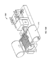
- FIG. 5 illustrates an embodiment of a controllable force driver in the form of a cylindrical electric lancet driver using a coiled solenoid -type configuration.
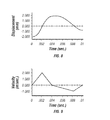
- FIG. 6 illustrates a displacement over time profile of a lancet driven by a harmonic spring/mass system.
- FIG. 8 illustrates a displacement over time profile of an embodiment of a controllable force driver.
- FIGS. 9 illustrates a velocity over time profile of an embodiment of a controllable force driver.
- FIG. 11 illustrates blood following the lancet needle to the skin surface, maintaining an open wound tract.
- FIG. 13 is a graph of force vs. time during the advancement and retraction of a lancet showing some characteristic phases of a lancing cycle.
- FIG. 15 illustrates an embodiment of a lancet tip.
- FIG. 16 is a graph showing displacement of a lancet over time.
- FIG. 18 illustrates the tip of an embodiment of a lancet before, during and after the creation of an incision braced with a helix.
- FIG. 20 is a perspective view of a tissue penetration device having features of the invention.
- FIG. 21 is an elevation view in partial longitudinal section of the tissue penetration device of FIG. 20 .
- FIG. 22 is an elevation view in partial section of an alternative embodiment.
- FIG. 28 is a front view of the drive coupler of the tissue penetration device of FIG. 21 with the lancet not shown for purposes of illustration.
- FIG. 30 is a diagrammatic view of a patient's finger and a lancet tip moving toward the skin of the finger.
- FIG. 32 is a diagrammatic view of the lancet tip depressing the skin of a patient's finger.
- FIG. 33 is a diagrammatic view of the lancet tip further depressing the skin of a patient's finger.
- FIG. 34 is a diagrammatic view of the lancet tip penetrating the skin of a patient's finger.
- FIGS. 37-41 illustrate a method of tissue penetration that may measure elastic recoil of the skin.
- FIG. 44 is a graphical representation of velocity vs. position of a lancing cycle.
- FIG. 45 is a graphical representation of velocity vs. time of a lancing cycle.
- FIG. 46 is an elevation view in partial longitudinal section of an alternative embodiment of a driver coil pack and position sensor.
- FIG. 47 is a perspective view of a flat coil driver having features of the invention.
- FIG. 48 is an exploded view of the flat coil driver of FIG. 47 .
- FIG. 49 is an elevational view in partial longitudinal section of a tapered driver coil pack having features of the invention.
- FIG. 51 shows an embodiment of a sampling module which houses a lancet and sample reservoir.
- FIG. 52 shows a housing that includes a driver and a chamber where the module shown in FIG. 51 can be loaded.
- FIG. 53 shows a tissue penetrating sampling device with the module loaded into the housing.
- FIG. 54 shows an alternate embodiment of a lancet configuration.
- FIG. 55 illustrates an embodiment of a sample input port, sample reservoir and ergonomically contoured finger contact area.
- FIG. 56 illustrates the tissue penetration sampling device during a lancing event.
- FIG. 57 illustrates a thermal sample sensor having a sample detection element near a surface over which a fluid may flow and an alternative position for a sampled detection element that would be exposed to a fluid flowing across the surface.
- FIG. 58 shows a configuration of a thermal sample sensor with a sample detection element that includes a separate heating element.
- FIG. 59 depicts three thermal sample detectors such as that shown in FIG. 58 with sample detection elements located near each other alongside a surface.
- FIG. 60 illustrates thermal sample sensors positioned relative to a channel having an analysis site.
- FIG. 61 shows thermal sample sensors with sample detection analyzers positioned relative to analysis sites arranged in an array on a surface.
- FIG. 62 schematically illustrates a sampling module device including several possible configurations of thermal sample sensors including sample detection elements positioned relative to sample flow channels and analytical regions.
- FIG. 64 is a top view in partial section of a sampling module of the tissue penetration sampling device of FIG. 63 .
- FIG. 65 is a cross sectional view through line 65 - 65 of the sampling module shown in FIG. 64 .
- FIG. 66 schematically depicts a sectional view of an alternative embodiment of the sampling module.
- FIG. 67 depicts a portion of the sampling module surrounding a sampling port.
- FIGS. 68-70 show in sectional view one implementation of a spring powered lancet driver in three different positions during use of the lancet driver.
- FIG. 71 illustrates an embodiment of a tissue penetration sampling device having features of the invention.
- FIG. 72 shows a top surface of a cartridge that includes multiple sampling modules.
- FIG. 73 shows in partial section a sampling module of the sampling cartridge positioned in a reader device.
- FIG. 74 is a perspective view in partial section of a tissue penetration sampling device with a cartridge of sampling modules.
- FIG. 76 is a top view of the tissue penetration sampling device of FIG. 75 .
- FIG. 78 is a perspective view of a single sampling module of the sampling module belt of FIG. 59 .
- FIG. 79 is a bottom view of a section of the flexible polymer sheet of the sampling module of FIG. 78 illustrating the flexible conductors and contact points deposited on the bottom surface of the flexible polymer sheet.
- FIG. 80 is a perspective view of the body portion of the sampling module of FIG. 77 without the flexible polymer cover sheet or lancet.
- FIG. 81 is an enlarged portion of the body portion of the sampling module of FIG. 80 illustrating the input port, sample flow channel, analytical region, lancet channel and lancet guides of the sampling module.
- FIG. 82 is an enlarged elevational view of a portion of an alternative embodiment of a sampling module having a plurality of small volume analytical regions.
- FIG. 83 is a perspective view of a body portion of a lancet module that can house and guide a lancet without sampling or analytical functions.
- FIG. 84 is an elevational view of a drive coupler having a T-slot configured to accept a drive head of a lancet.
- FIG. 85 is an elevational view of the drive coupler of FIG. 84 from the side and illustrating the guide ramps of the drive coupler.
- FIG. 86 is a perspective view of the drive coupler of FIG. 84 with a lancet being loaded into the T-slot of the drive coupler.
- FIG. 87 is a perspective view of the drive coupler of FIG. 86 with the drive head of the lancet completely loaded into the T-slot of the drive coupler.
- FIG. 88 is a perspective view of a sampling module belt disposed within the T-slot of the drive coupler with a drive head of a lancet of one of the sampling modules loaded within the T-slot of the drive coupler.
- FIG. 89 is a perspective view of a sampling module cartridge with the sampling modules arranged in a ring configuration.
- FIG. 90 is a perspective view of a sampling module cartridge with the plurality of sampling modules arranged in a block matrix with lancet drive heads configured to mate with a drive coupler having adhesive coupling.
- FIG. 91 is a side view of an alternative embodiment of a drive coupler having a lateral slot configured to accept the L-shaped drive head of the lancet that is disposed within a lancet module and shown with the L-shaped drive head loaded in the lateral slot.
- FIG. 92 is an exploded view of the drive coupler, lancet with L-shaped drive head and lancet module of FIG. 91 .
- FIG. 93 is a perspective view of the front of a lancet cartridge coupled to the distal end of a controlled electromagnetic driver.
- FIG. 94 is an elevational front view of the lancet cartridge of FIG. 93 .
- FIG. 95 is a top view of the lancet cartridge of FIG. 93 .
- FIG. 96 is a perspective view of the lancet cartridge of FIG. 93 with a portion of the cartridge body and lancet receptacle not shown for purposes of illustration of the internal mechanism.
- FIGS. 97-101 illustrate an embodiment of an agent injection device.
- FIGS. 102-106 illustrate an embodiment of a cartridge for use in sampling having a sampling cartridge body and a lancet cartridge body.
- FIG. 107 is a schematic showing a lancet driver having a driver force generator and a sensor according to the present invention.
- FIG. 108 is a schematic showing one embodiment of the lancet driver using closed loop control.
- FIG. 109 is a schematic showing one embodiment of the lancet driver using a damper.
- FIGS. 110A and 110B show embodiments of the lancet driver for use with multiple lancets.
- FIGS. 111-115 illustrate embodiments of a lancet driver with a variety of different interface devices.
- FIGS. 116( a ) and 116( b ) illustrate top and side views of embodiments of a lancet driver with a multi-switch user interface of the present invention.
- FIG. 117 illustrates an embodiment of a lancet driver of the present invention with an LED.
- FIG. 118 illustrates an embodiment of a lancet driver of the present invention with a semi-transparent lancet window.
- Variations in skin thickness including the stratum corneum and hydration of the epidermis can yield different results between different users with existing tissue penetration devices, such as lancing devices wherein the tissue penetrating element of the tissue penetration device is a lancet.
- tissue penetration devices such as lancing devices wherein the tissue penetrating element of the tissue penetration device is a lancet.
- Many current devices rely on adjustable mechanical stops or damping, to control the lancet's depth of penetration.
- FIGS. 1 and 2 Displacement velocity profiles for both spring driven and cam driven tissue penetration devices are shown in FIGS. 1 and 2 , respectively.
- Velocity is plotted against displacement X of the lancet.
- FIG. 1 represents a displacement/velocity profile typical of spring driven devices.
- the lancet exit velocity increases until the lancet hits the surface of the skin 10 . Because of the tensile characteristics of the skin, it will bend or deform until the lancet tip cuts the surface 20 , the lancet will then penetrate the skin until it reaches a full stop 30 . At this point displacement is maximal and reaches a limit of penetration and the lancet stops. Mechanical stops absorb excess energy from the driver and transfer it to the lancet.
- the energy stored in the spring can cause recoil resulting in multiple piercing as seen by the coiled profile in FIG. 1 . This results in unnecessary pain from the additional tissue penetration as well as from transferring vibratory energy into the skin and exciting nerve endings. Retraction of the lancet then occurs and the lancet exits the skin 40 to return into the housing. Velocity cannot be controlled in any meaningful way for this type of spring-powered driver.
- FIG. 2 shows a displacement/velocity profile for a cam driven driver, which is similar to that of FIG. 1 , but because the return path is specified in the cam configuration, there is no possibility of multiple tissue penetrations from one actuation.
- Cam based drivers can offer some level of control of lancet velocity vs. displacement, but not enough to achieve many desirable displacement/velocity profiles.
- Embodiments of the present invention allow for the ability to accurately control depth of penetration, to control lancet penetration and withdrawal velocity, and therefore reduce the pain perceived when cutting into the skin.
- Embodiments of the invention include a controllable driver that can be used with a feedback loop with a position sensor to control the power delivered to the lancet, which can optimize the velocity and displacement profile to compensate for variations in skin thickness
- Pain reduction can be achieved by using a rapid lancet cutting speed, which is facilitated by the use of a lightweight lancet.
- the rapid cutting minimizes the shock waves produced when the lancet strikes the skin in addition to compressing the skin for efficient cutting. If a controllable driver is used, the need for a mechanical stop can be eliminated. Due to the very light mass of the lancet and lack of a mechanical stop, there is little or no vibrational energy transferred to the finger during cutting.
- the lancing devices such as those whose velocity versus position profiles are shown in FIGS. 1 and 2 typically yield 50% spontaneous blood.
- some lancing events are unsuccessful and yield no blood, even on milking the finger.
- a spontaneous blood droplet generation is dependent on reaching the blood capillaries and venuoles, which yield the blood sample. It is therefore an issue of correct depth of penetration of the cutting device. Due to variations in skin thickness and hydration, some types of skin will deform more before cutting starts, and hence the actual depth of penetration will be less, resulting in less capillaries and venuoles cut.
- a controllable force driver can control the depth of penetration of a lancet and hence improve the spontaneity of blood yield. Furthermore, the use of a controllable force driver can allow for slow retraction of the lancet (slower than the cutting velocity) resulting in improved success rate due to the would channel remaining open for the free passage of blood to the surface of the skin.
- An electromagnetic driver can be coupled directly to the lancet minimizing the mass of the lancet and allowing the driver to bring the lancet to a stop at a predetermined depth without the use of a mechanical stop. Alternatively, if a mechanical stop is required for positive positioning, the energy transferred to the stop can be minimized.
- the electromagnetic driver allows programmable control over the velocity vs. position profile of the entire lancing process including timing the start of the lancet, tracking the lancet position, measuring the lancet velocity, controlling the distal stop acceleration, and controlling the skin penetration depth.
- the tissue penetration device includes a controllable force driver in the form of an electromagnetic driver, which can be used to drive a lancet.
- Lancet generally includes any sharp or blunt member, preferably having a relatively low mass, used to puncture the skin for the purpose of cutting blood vessels and allowing blood to flow to the surface of the skin.
- Electromagnetic driver generally includes any device that moves or drives a tissue penetrating element, such as a lancet under an electrically or magnetically induced force.
- FIG. 4 is a partially exploded view of an embodiment of an electromagnetic driver. The top half of the driver is shown assembled. The bottom half of the driver is shown exploded for illustrative purposes.
- FIG. 4 shows the inner insulating housing 22 separated from the stationary housing or PC board 20 , and the lancet 24 and flag 26 assembly separated from the inner insulating housing 22 for illustrative purposes.
- only four rivets 18 are shown as attached to the inner insulating housing 22 and separated from the PC board 20 .
- each coil drive field core in the PC board located in the PC Board 20 and 30 is connected to the inner insulating housing 22 and 32 with rivets.
- the electromagnetic driver has a moving part comprising a lancet assembly with a lancet 24 and a magnetically permeable flag 26 attached at the proximal or drive end and a stationary part comprising a stationary housing assembly with electric field coils arranged so that they produce a balanced field at the flag to reduce or eliminate any net lateral force on the flag.
- the electric field coils are generally one or more metal coils, which generate a magnetic field when electric current passes through the coil.
- the iron flag is a flat or enlarged piece of magnetic material, which increases the surface area of the lancet assembly to enhance the magnetic forces generated between the proximal end of the lancet and a magnetic field produced by the field coils. The combined mass of the lancet and the iron flag can be minimized to facilitate rapid acceleration for introduction into the skin of a patient, to reduce the impact when the lancet stops in the skin, and to facilitate prompt velocity profile changes throughout the sampling cycle.
- the stationary housing assembly consists of a PC board 20 , a lower inner insulating housing 22 , an upper inner insulating housing 32 , an upper PC board 30 , and rivets 18 assembled into a single unit.
- the lower and upper inner insulating housing 22 and 32 are relieved to form a slot so that lancet assembly can be slid into the driver assembly from the side perpendicular to the direction of the lancet's advancement and retraction. This allows the disposal of the lancet assembly and reuse of the stationary housing assembly with another lancet assembly while avoiding accidental lancet launches during replacement.
- the electric field coils in the upper and lower stationary housing 20 and 30 are fabricated in a multi-layer printed circuit (PC) board. They may also be conventionally wound wire coils.
- PC printed circuit
- a Teflon® material, or other low friction insulating material is used to construct the lower and upper inner insulating housing 22 and 32 .
- Each insulating housing is mounted on the PC board to provide electrical insulation and physical protection, as well as to provide a low-friction guide for the lancet.
- the lower and upper inner insulating housing 22 and 32 provide a reference surface with a small gap so that the lancet assembly 24 and 26 can align with the drive field coils in the PC board for good magnetic coupling.
- Rivets 18 connect the lower inner insulating housing 22 to the lower stationary housing 20 and are made of magnetically permeable material such as ferrite or steel, which serves to concentrate the magnetic field. This mirrors the construction of the upper inner insulating housing 32 and upper stationary housing 30 . These rivets form the poles of the electric field coils.
- the PC board is fabricated with multiple layers of coils or with multiple boards. Each layer supports spiral traces around a central hole. Alternate layers spiral from the center outwards or from the edges inward. In this way each layer connects via simple feed-through holes, and the current always travels in the same direction, summing the ampere-turns.
- the PC boards within the lower and upper stationary housings 20 and 30 are connected to the lower and upper inner insulating housings 22 and 32 with the rivets 18 .
- the lower and upper inner insulating housings 22 and 32 expose the rivet heads on opposite ends of the slot where the lancet assembly 24 and 26 travels.
- the magnetic field lines from each rivet create magnetic poles at the rivet heads.
- An iron bar on the opposite side of the PC board within each of the lower and upper stationary housing 20 and 30 completes the magnetic circuit by connecting the rivets.
- Any fastener made of magnetically permeable material such as iron or steel can be used In place of the rivets.
- a single component made of magnetically permeable material and formed in a horseshoe shape can be used in place of the rivet/screw and iron bar assembly.
- the magnetically permeable flag 26 attached to the lancet 24 is divided into slits and bars 34 .
- the slit patterns are staggered so that coils can drive the flag 26 in two, three or more phases.
- Both lower and upper PC boards 20 and 30 contain drive coils so that there is a symmetrical magnetic field above and below the flag 26 .
- a magnetic field is established around the bars between the slits of the magnetically permeable iron on the flag 26 .
- the bars of the flag experience a force that tends to move the magnetically permeable material to a position minimizing the number and length of magnetic field lines and conducting the magnetic field lines between the magnetic poles.
- a three phase, three-pole design or a shading coil that is offset by one-quarter pitch establishes the direction of travel.
- the lower and upper PC boards 20 and 30 shown in FIG. 4 contain electric field coils, which drive the lancet assembly and the circuitry for controlling the entire electromagnetic driver.
- the embodiment described above generally uses the principles of a magnetic attraction drive, similar to commonly available circular stepper motors (Hurst Manufacturing BA Series motor, or “Electrical Engineering Handbook” Second edition p 1472-1474, 1997). These references are hereby incorporated by reference.
- Other embodiments can include a linear induction drive that uses a changing magnetic field to induce electric currents in the lancet assembly. These induced currents produce a secondary magnetic field that repels the primary field and applies a net force on the lancet assembly.
- the linear induction drive uses an electrical drive control that sweeps a magnetic field from pole to pole, propelling the lancet before it. Varying the rate of the sweep and the magnitude of the field by altering the driving voltage and frequency controls the force applied to the lancet assembly and its velocity.
- the arrangement of the coils and rivets to concentrate the magnetic flux also applies to the induction design creating a growing magnetic field as the electric current in the field switches on.
- This growing magnetic field creates an opposing electric current in the conductive flag.
- the flag In a linear induction motor the flag is electrically conductive, and its magnetic properties are unimportant. Copper or aluminum are materials that can be used for the conductive flags. Copper is generally used because of its good electrical conductivity.
- the opposing electrical field produces an opposing magnetic field that repels the field of the coils.
- a moving field can be generated which pushes the flag along just below the synchronous speed of the coils.
- the flag can be moved at a desired speed.
- FIG. 5 shows another embodiment of a solenoid type electromagnetic driver that is capable of driving an iron core or slug mounted to the lancet assembly using a direct current (DC) power supply.
- the electromagnetic driver includes a driver coil pack that is divided into three separate coils along the path of the lancet, two end coils and a middle coil. Direct current is alternated to the coils to advance and retract the lancet.
- the driver coil pack is shown with three coils, any suitable number of coils may be used, for example, 4, 5, 6, 7 or more coils may be used.
- the stationary iron housing 40 contains the driver coil pack with a first coil 52 is flanked by iron spacers 50 which concentrate the magnetic flux at the inner diameter creating magnetic poles.
- the inner insulating housing 48 isolates the lancet 42 and iron core 46 from the coils and provides a smooth, low friction guide surface.
- the lancet guide 44 further centers the lancet 42 and iron core 46 .
- the lancet 42 is protracted and retracted by alternating the current between the first coil 52 , the middle coil, and the third coil to attract the iron core 46 . Reversing the coil sequence and attracting the core and lancet back into the housing retracts the lancet.
- the lancet guide 44 also serves as a stop for the iron core 46 mounted to the lancet 42 .
- tissue penetration devices which employ spring or cam driving methods have a symmetrical or nearly symmetrical actuation displacement and velocity profiles on the advancement and retraction of the lancet as shown in FIGS. 6 and 7 .
- the stored energy determines the velocity profile until the energy is dissipated.
- Controlling impact, retraction velocity, and dwell time of the lancet within the tissue can be useful in order to achieve a high success rate while accommodating variations in skin properties and minimize pain.
- Advantages can be achieved by taking into account that tissue dwell time is related to the amount of skin deformation as the lancet tries to puncture the surface of the skin and variance in skin deformation from patient to patient based on skin hydration.
- FIG. 8 illustrates an embodiment of a controlled displacement profile
- FIG. 9 illustrates an embodiment of a the controlled velocity profile.
- Reduced pain can be achieved by using impact velocities of greater than 2 m/s entry of a tissue penetrating element, such as a lancet, into tissue.
- Retraction of the lancet at a low velocity following the sectioning of the venuole/capillary mesh allows the blood to flood the wound tract and flow freely to the surface, thus using the lancet to keep the channel open during retraction as shown in FIGS. 10 and 11 .
- Low-velocity retraction of the lancet near the wound flap prevents the wound flap from sealing off the channel.
- the ability to slow the lancet retraction directly contributes to increasing the success rate of obtaining blood.
- Increasing the sampling success rate to near 100% can be important to the combination of sampling and acquisition into an integrated sampling module such as an integrated glucose-sampling module, which incorporates a glucose test strip.
- the lancet and lancet driver are configured so that feedback control is based on lancet displacement, velocity, or acceleration.
- the feedback control information relating to the actual lancet path is returned to a processor such as that illustrated in FIG. 12 that regulates the energy to the driver, thereby precisely controlling the lancet throughout its advancement and retraction.
- the driver may be driven by electric current, which includes direct current and alternating current.
- the drive voltage can be turned off, allowing the coils to relax, and then the cycle is repeated.
- the degree of magnetic coupling between the coils is converted electronically to a proportional DC voltage that is supplied to an analog-to-digital converter.
- the digitized position signal is then processed and compared to a desired “nominal” position by a central processing unit (CPU).
- the CPU to set the level and/or length of the next power pulse to the solenoid coils uses error between the actual and nominal positions.
- the driver coil pack has three coils consisting of a central driving coil flanked by balanced detection coils built into the driver assembly so that they surround an actuation or magnetically active region with the region centered on the middle coil at mid-stroke.
- a current pulse is applied to the central coil, voltages are induced in the adjacent sense coils. If the sense coils are connected together so that their induced voltages oppose each other, the resulting signal will be positive for deflection from mid-stroke in one direction, negative in the other direction, and zero at mid-stroke.
- This measuring technique is commonly used in Linear Variable Differential Transformers (LVDT). Lancet position is determined by measuring the electrical balance between the two sensing coils.
- LVDT Linear Variable Differential Transformers
- a feedback loop can use a commercially available LED/photo transducer module such as the OPB703 manufactured by Optek Technology, Inc., 1215 W. Crosby Road, Carrollton, Tex., 75006 to determine the distance from the fixed module on the stationary housing to a reflective surface or target mounted on the lancet assembly.
- the LED acts as a light emitter to send light beams to the reflective surface, which in turn reflects the light back to the photo transducer, which acts as a light sensor. Distances over the range of 4 mm or so are determined by measuring the intensity of the reflected light by the photo transducer.
- a feedback loop can use a magnetically permeable region on the lancet shaft itself as the core of a Linear Variable Differential Transformer (LVDT).
- LVDT Linear Variable Differential Transformer
- the feedback control supplies a piezoelectric driver, superimposing a high frequency oscillation on the basic displacement profile.
- the piezoelectric driver provides improved cutting efficiency and reduces pain by allowing the lancet to “saw” its way into the tissue or to destroy cells with cavitation energy generated by the high frequency of vibration of the advancing edge of the lancet.
- the drive power to the piezoelectric driver is monitored for an impedance shift as the device interacts with the target tissue.
- the resulting force measurement, coupled with the known mass of the lancet is used to determine lancet acceleration, velocity, and position.
- FIG. 12 illustrates the operation of a feedback loop using a processor.
- the processor 60 stores profiles 62 in non-volatile memory.
- a user inputs information 64 about the desired circumstances or parameters for a lancing event.
- the processor 60 selects a driver profile 62 from a set of alternative driver profiles that have been preprogrammed in the processor 60 based on typical or desired tissue penetration device performance determined through testing at the factory or as programmed in by the operator.
- the processor 60 may customize by either scaling or modifying the profile based on additional user input information 64 .
- the processor 60 is ready to modulate the power from the power supply 66 to the lancet driver 68 through an amplifier 70 .
- the processor 60 measures the location of the lancet 72 using a position sensing mechanism 74 through an analog to digital converter 76 . Examples of position sensing mechanisms have been described in the embodiments above.
- the processor 60 calculates the movement of the lancet by comparing the actual profile of the lancet to the predetermined profile.
- the processor 60 modulates the power to the lancet driver 68 through a signal generator 78 , which controls the amplifier 70 so that the actual profile of the lancet does not exceed the predetermined profile by more than a preset error limit.
- the error limit is the accuracy in the control of the lancet.
- the processor 60 can allow the user to rank the results of the lancing event.
- the processor 60 stores these results and constructs a database 80 for the individual user.
- the processor 60 calculates the profile traits such as degree of painlessness, success rate, and blood volume for various profiles 62 depending on user input information 64 to optimize the profile to the individual user for subsequent lancing cycles. These profile traits depend on the characteristic phases of lancet advancement and retraction.
- the processor 60 uses these calculations to optimize profiles 62 for each user.
- an internal clock allows storage in the database 80 of information such as the time of day to generate a time stamp for the lancing event and the time between lancing events to anticipate the user's diurnal needs.
- the database stores information and statistics for each user and each profile that particular user uses.
- the processor 60 can be used to calculate the appropriate lancet diameter and geometry necessary to realize the blood volume required by the user. For example, if the user requires a 1-5 micro liter volume of blood, the processor selects a 200 micron diameter lancet to achieve these results. For each class of lancet, both diameter and lancet tip geometry, is stored in the processor to correspond with upper and lower limits of attainable blood volume based on the predetermined displacement and velocity profiles.
- the lancing device is capable of prompting the user for information at the beginning and the end of the lancing event to more adequately suit the user.
- the goal is to either change to a different profile or modify an existing profile.
- the force driving the lancet is varied during advancement and retraction to follow the profile.
- the method of lancing using the lancing device comprises selecting a profile, lancing according to the selected profile, determining lancing profile traits for each characteristic phase of the lancing cycle, and optimizing profile traits for subsequent lancing events.
- FIG. 13 shows an embodiment of the characteristic phases of lancet advancement and retraction on a graph of force versus time illustrating the force exerted by the lancet driver on the lancet to achieve the desired displacement and velocity profile.
- the characteristic phases are the lancet introduction phase A-C where the lancet is longitudinally advanced into the skin, the lancet rest phase D where the lancet terminates its longitudinal movement reaching its maximum depth and becoming relatively stationary, and the lancet retraction phase E-G where the lancet is longitudinally retracted out of the skin.
- the duration of the lancet retraction phase E-G is longer than the duration of the lancet introduction phase A-C, which in turn is longer than the duration of the lancet rest phase D.
- the lancet retraction phase further comprises a primary retraction phase E when the skin pushes the lancet out of the wound tract, a secondary retraction phase F when the lancet starts to become dislodged and pulls in the opposite direction of the skin, and lancet exit phase G when the lancet becomes free of the skin.
- Primary retraction is the result of exerting a decreasing force to pull the lancet out of the skin as the lancet pulls away from the finger.
- Secondary retraction is the result of exerting a force in the opposite direction to dislodge the lancet. Control is necessary to keep the wound tract open as blood flows up the wound tract.
- FIG. 14 shows a standard industry lancet for glucose testing which has a three-facet geometry. Taking a rod of diameter 114 and grinding 8 degrees to the plane of the primary axis to create the primary facet 110 produces the lancet 116 . The secondary facets 112 are then created by rotating the shaft of the needle 15 degrees, and then rolling over 12 degrees to the plane of the primary facet. Other possible geometry's require altering the lancet's production parameters such as shaft diameter, angles, and translation distance.
- FIG. 15 illustrates facet and tip geometry 120 and 122 , diameter 124 , and depth 126 which are significant factors in reducing pain, blood volume and success rate. It is known that additional cutting by the lancet is achieved by increasing the shear percentage or ratio of the primary to secondary facets, which when combined with reducing the lancet's diameter reduces skin tear and penetration force and gives the perception of less pain. Overall success rate of blood yield, however, also depends on a variety of factors, including the existence of facets, facet geometry, and skin anatomy.
- FIG. 16 shows another embodiment of displacement versus time profile of a lancet for a controlled lancet retraction.
- FIG. 17 shows the velocity vs. time profile of the lancet for the controlled retraction of FIG. 16 .
- the lancet driver controls lancet displacement and velocity at several steps in the lancing cycle, including when the lancet cuts the blood vessels to allow blood to pool 130 , and as the lancet retracts, regulating the retraction rate to allow the blood to flood the wound tract while keeping the wound flap from sealing the channel 132 to permit blood to exit the wound.
- FIG. 18 shows the use of an embodiment of the invention, which includes a retractable coil on the lancet tip.
- a coiled helix or tube 140 is attached externally to lancet 116 with the freedom to slide such that when the lancet penetrates the skin 150 , the helix or tube 140 follows the trajectory of the lancet 116 .
- the helix begins the lancing cycle coiled around the facets and shaft of the lancet 144 . As the lancet penetrates the skin, the helix braces the wound tract around the lancet 146 .
- the tube or helix 140 is made of wire or metal of the type commonly used in angioplasty stents such as stainless steel, nickel titanium alloy or the like.
- the tube or helix 140 or a ring can be made of a biodegradable material, which braces the wound tract by becoming lodged in the skin. Biodegradation is completed within seconds or minutes of insertion, allowing adequate time for blood to pool and flow up the wound tract. Biodegradation is activated by heat, moisture, or pH from the skin.
- the wound could be held open by coating the lancet with a powder or other granular substance.
- the powder coats the wound tract and keeps it open when the lancet is withdrawn.
- the powder or other granular substance can be a coarse bed of microspheres or capsules which hold the channel open while allowing blood to flow through the porous interstices.
- FIG. 19 shows a further embodiment of a method and device for facilitating blood flow utilizing an elastomer to coat the wound.
- This method uses an elastomer 154 , such as silicon rubber, to coat or brace the wound tract 156 by covering and stretching the surface of the finger 158 .
- the elastomer 154 is applied to the finger 158 prior to lancing. After a short delay, the lancet (not shown) then penetrates the elastomer 154 and the skin on the surface of the finger 158 as is seen in 160 . Blood is allowed to pool and rise to the surface while the elastomer 154 braces the wound tract 156 as is seen in 162 and 164 .
- Other known mechanisms for increasing the success rate of blood yield after lancing can include creating a vacuum, suctioning the wound, applying an adhesive strip, vibration while cutting, or initiating a second lance if the first is unsuccessful.
- FIG. 20 illustrates an embodiment of a tissue penetration device, more specifically, a lancing device 180 that includes a controllable driver 179 coupled to a tissue penetration element.
- the lancing device 180 has a proximal end 181 and a distal end 182 .
- the tissue penetration element in the form of a lancet 183 , which is coupled to an elongate coupler shaft 184 by a drive coupler 185 .
- the elongate coupler shaft 184 has a proximal end 186 and a distal end 187 .
- a driver coil pack 188 is disposed about the elongate coupler shaft 184 proximal of the lancet 183 .
- a position sensor 191 is disposed about a proximal portion 192 of the elongate coupler shaft 184 and an electrical conductor 194 electrically couples a processor 193 to the position sensor 191 .
- the elongate coupler shaft 184 driven by the driver coil pack 188 controlled by the position sensor 191 and processor 193 form the controllable driver, specifically, a controllable electromagnetic driver.
- the lancet 183 has a proximal end 195 and a distal end 196 with a sharpened point at the distal end 196 of the lancet 183 and a drive head 198 disposed at the proximal end 195 of the lancet 183 .
- a lancet shaft 201 is disposed between the drive head 198 and the sharpened point 197 .
- the lancet shaft 201 may be comprised of stainless steel, or any other suitable material or alloy and have a transverse dimension of about 0.1 to about 0.4 mm.
- a magnetic member 202 is secured to the elongate coupler shaft 184 proximal of the drive coupler 185 on a distal portion 203 of the elongate coupler shaft 184 .
- the magnetic member 202 is a substantially cylindrical piece of magnetic material having an axial lumen 204 extending the length of the magnetic member 202 .
- the magnetic member 202 has an outer transverse dimension that allows the magnetic member 202 to slide easily within an axial lumen 205 of a low friction, possibly lubricious, polymer guide tube 205 ′ disposed within the driver coil pack 188 .
- the magnetic member 202 may have an outer transverse dimension of about 1.0 to about 5.0 mm, specifically, about 2.3 to about 2.5 mm.
- the magnetic member 202 may have a length of about 3.0 to about 5.0 mm, specifically, about 4.7 to about 4.9 mm.
- the magnetic member 202 can be made from a variety of magnetic materials including ferrous metals such as ferrous steel, iron, ferrite, or the like.
- the magnetic member 202 may be secured to the distal portion 203 of the elongate coupler shaft 184 by a variety of methods including adhesive or epoxy bonding, welding, crimping or any other suitable method.
- an optical encoder flag 206 is secured to the elongate coupler shaft 184 .
- the optical encoder flag 206 is configured to move within a slot 207 in the position sensor 191 .
- the slot 207 of the position sensor 191 is formed between a first body portion 208 and a second body portion 209 of the position sensor 191 .
- the slot 207 may have separation width of about 1.5 to about 2.0 mm.
- the optical encoder flag 206 can have a length of about 14 to about 18 mm, a width of about 3 to about 5 mm and a thickness of about 0.04 to about 0.06 mm.
- the optical encoder flag 206 interacts with various optical beams generated by LEDs disposed on or in the position sensor body portions 208 and 209 in a predetermined manner.
- the interaction of the optical beams generated by the LEDs of the position sensor 191 generates a signal that indicates the longitudinal position of the optical flag 206 relative to the position sensor 191 with a substantially high degree of resolution.
- the resolution of the position sensor 191 may be about 200 to about 400 cycles per inch, specifically, about 350 to about 370 cycles per inch.
- the position sensor 191 may have a speed response time (position/time resolution) of 0 to about 120,000 Hz, where one dark and light stripe of the flag constitutes one Hertz, or cycle per second.
- the position of the optical encoder flag 206 relative to the magnetic member 202 , driver coil pack 188 and position sensor 191 is such that the optical encoder 191 can provide precise positional information about the lancet 183 over the entire length of the lancet's power stroke.
- An optical encoder that is suitable for the position sensor 191 is a linear optical incremental encoder, model HEDS 9200, manufactured by Agilent Technologies.
- the model HEDS 9200 may have a length of about 20 to about 30 mm, a width of about 8 to about 12 mm, and a height of about 9 to about 11 mm.
- the position sensor 191 illustrated is a linear optical incremental encoder, other suitable position sensor embodiments could be used, provided they posses the requisite positional resolution and time response.
- the HEDS 9200 is a two channel device where the channels are 90 degrees out of phase with each other. This results in a resolution of four times the basic cycle of the flag. These quadrature outputs make it possible for the processor to determine the direction of lancet travel.
- Other suitable position sensors include capacitive encoders, analog reflective sensors, such as the reflective position sensor discussed above, and the like.
- a coupler shaft guide 211 is disposed towards the proximal end 181 of the lancing device 180 .
- the guide 211 has a guide lumen 212 disposed in the guide 211 to slidingly accept the proximal portion 192 of the elongate coupler shaft 184 .
- the guide 211 keeps the elongate coupler shaft 184 centered horizontally and vertically in the slot 202 of the optical encoder 191 .
- the driver coil pack 188 , position sensor 191 and coupler shaft guide 211 are all secured to a base 213 .
- the base 213 is longitudinally coextensive with the driver coil pack 188 , position sensor 191 and coupler shaft guide 211 .
- the base 213 can take the form of a rectangular piece of metal or polymer, or may be a more elaborate housing with recesses, which are configured to accept the various components of the lancing device 180 .
- Axially adjacent each of the coils 214 - 217 is a magnetic disk or washer 218 that augments completion of the magnetic circuit of the coils 214 - 217 during a lancing cycle of the device 180 .
- the magnetic washers 218 of the embodiment of FIG. 21 are made of ferrous steel but could be made of any other suitable magnetic material, such as iron or ferrite.
- the outer shell 189 of the driver coil pack 188 is also made of iron or steel to complete the magnetic path around the coils and between the washers 218 .
- the magnetic washers 218 have an outer diameter commensurate with an outer diameter of the driver coil pack 188 of about 4.0 to about 8.0 mm.
- the magnetic washers 218 have an axial thickness of about 0.05, to about 0.4 mm, specifically, about 0.15 to about 0.25 mm.
- Each coil 214 - 217 can have an axial length of about 1.0 to about 3.0 mm, specifically, about 1.8 to about 2.0 mm.
- Each coil 214 - 217 can have an outer transverse dimension or diameter of about 4.0, to about 2.0 mm, specifically, about 9.0 to about 12.0 mm.
- the axial lumen 205 can have a transverse dimension of about 1.0 to about 3.0 mm.
- driver coil 188 it may be advantageous in some driver coil 188 embodiments to replace one or more of the coils with permanent magnets, which produce a magnetic field similar to that of the coils when the coils are activated.
- Having a fixed zero or start point for the elongate coupler shaft 184 and lancet 183 can be critical to properly controlling the depth of penetration of the lancet 183 as well as other lancing parameters. This can be because some methods of depth penetration control for a controllable driver measure the acceleration and displacement of the elongate coupler shaft 184 and lancet 183 from a known start position. If the distance of the lancet tip 196 from the target tissue is known, acceleration and displacement of the lancet is known and the start position of the lancet is know, the time and position of tissue contact and depth of penetration can be determined by the processor 193 .
- the polymer non-magnetic disc spacer 219 ′′ is used so that the magnetic member 202 can be centered in a zero or start position slightly proximal of the proximal-most coil 217 of the driver coil pack 188 . This allows the magnetic member to be attracted by the proximal-most coil 217 at the initiation of the lancing cycle instead of being passive in the forward drive portion of the lancing cycle.
- Electrical conductors 222 couple the driver coil pack 188 with the processor 193 which can be configured or programmed to control the current flow in the coils 214 - 217 of the driver coil pack 188 based on position feedback from the position sensor 191 , which is coupled to the processor 193 by electrical conductors 194 .
- a power source 225 is electrically coupled to the processor 193 and provides electrical power to operate the processor 193 and power the coil driver pack 188 .
- the power source 225 may be one or more batteries that provide direct current power to the 193 processor.
- FIG. 23 shows a transverse cross sectional view of drive coupler 185 in more detail.
- the drive head 198 of the lancet 183 is disposed within the drive coupler 185 with a first retaining rail 226 and second retaining rail 227 capturing the drive head 198 while allowing the drive head 198 to be inserted laterally into the drive coupler 185 and retracted laterally with minimal mechanical resistance.
- the drive coupler 185 may optionally be configured to include snap ridges 228 which allow the drive head 198 to be laterally inserted and retracted, but keep the drive head 198 from falling out of the drive coupler 185 unless a predetermined amount of externally applied lateral force is applied to the drive head 198 of the lancet 183 towards the lateral opening 231 of the drive coupler 185 .
- FIG. 27 shows an enlarged side view into the coupler opening 231 of the drive coupler 185 showing the snap ridges 228 disposed in the lateral opening 231 and the retaining rails 226 and 227 .
- FIG. 28 shows an enlarged front view of the drive coupler 185 .
- FIGS. 29A-29C a flow diagram is shown that describes the operations performed by the processor 193 in controlling the lancet 183 of the lancing device 180 discussed above during an operating cycle.
- FIGS. 30-36 illustrate the interaction of the lancet 183 and skin 233 of the patient's finger 234 during an operation cycle of the lancet device 183 .
- the processor 193 operates under control of programming steps that are stored in an associated memory. When the programming steps are executed, the processor 193 performs operations as described herein. Thus, the programming steps implement the functionality of the operations described with respect to the flow diagram of FIG. 29 .
- the processor 193 can receive the programming steps from a program product stored in recordable media, including a direct access program product storage device such as a hard drive or flash ROM, a removable program product storage device such as a floppy disk, or in any other manner known to those of skill in the art.
- the processor 193 can also download the programming steps through a network connection or serial connection.
- the processor 193 also causes the lancet to assume an initial stationary position.
- the lancet 183 is typically fully retracted such that the magnetic member 202 is positioned substantially adjacent the fourth coil 217 of the driver coil pack 188 , shown in FIG. 21 above.
- the processor 193 can move the lancet 183 to the initial stationary position by pulsing an electrical current to the fourth coil 217 to thereby attract the magnetic member 202 on the lancet 183 to the fourth coil 217 .
- the magnetic member can be positioned in the initial stationary position by virtue of a permanent magnet, such as bar magnet 219 , disc magnet 219 ′ or any other suitable magnet as discussed above with regard to the tissue penetration device illustrated in FIGS. 20 and 21 .
- the processor 193 In the next operation, represented by the flow diagram box numbered 247 , the processor 193 energizes one or more of the coils in the coil pack 188 . This should cause the lancet 183 to begin to move (i.e., achieve a non-zero speed) toward the skin target 233 . The processor 193 then determines whether or not the lancet is indeed moving, as represented by the decision box numbered 249 . The processor 193 can determine whether the lancet 183 is moving by monitoring the position of the lancet 183 to determine whether the position changes over time.
- the processor 193 can monitor the position of the lancet 183 by keeping track of the position of the optical encoder flag 206 secured to the elongate coupler shaft 184 wherein the encoder 191 produces a signal coupled to the processor 193 that indicates the spatial position of the lancet 183 .
- the process proceeds to the operation represented by the flow diagram box numbered 253 , where the processor deems that an error condition is present. This means that some error in the system is causing the lancet 183 not to move.
- the error may be mechanical, electrical, or software related.
- the lancet 183 may be stuck in the stationary position because something is impeding its movement.
- the processor 193 can cause an electrical current to be sent to the third coil 216 so that the third coil 216 attracts the magnetic member 202 and causes the magnetic member 202 to move from a position adjacent the fourth coil 217 toward the third coil 216 .
- the processor preferably determines which coil 214 - 217 should be used to attract the magnetic member 202 based on the position of the magnetic member 202 relative to the coils 214 - 217 . In this manner, the processor 193 provides a controlled force to the lancet that controls the movement of the lancet.
- the processor 193 may successively transition the current between coils 214 - 217 so that as the magnetic member 202 moves past a particular coil 214 - 217 , the processor 193 then shuts off current to that coil 214 - 217 and then applies current to another coil 214 - 217 that will attract the magnetic member 202 and cause the magnetic member 202 to continue to move in the desired direction.
- the processor 193 can take into account various factors, including the speed of the lancet 183 , the position of the lancet 183 relative to the coils 214 - 217 , the number of coils 214 - 217 , and the level of current to be applied to the coils 214 - 217 to achieve a desired speed or acceleration.
- the processor 193 determines whether the cutting or distal end tip 196 of the lancet 183 has contacted the patient's skin 233 , as shown in FIG. 31 and as represented by the decision box numbered 265 in FIG. 29B .
- the processor 193 may determine whether the lancet 183 has made contact with the target tissue 233 by a variety of methods, including some that rely on parameters which are measured prior to initiation of a lancing cycle and other methods that are adaptable to use during a lancing cycle without any predetermined parameters.
- the processor 193 determines that the skin has been contacted when the end tip 196 of the lancet 183 has moved a predetermined distance with respect to its initial position. If the distance from the tip 961 of the lancet 183 to the target tissue 233 is known prior to initiation of lancet 183 movement, the initial position of the lancet 183 is fixed and known, and the movement and position of the lancet 183 can be accurately measured during a lancing cycle, then the position and time of lancet contact can be determined.
- This method requires an accurate measurement of the distance between the lancet tip 196 and the patient's skin 233 when the lancet 183 is in the zero time or initial position. This can be accomplished in a number of ways. One way is to control all of the mechanical parameters that influence the distance from the lancet tip 196 to the patient's tissue or a surface of the lancing device 180 that will contact the patient's skin 233 . This could include the start position of the magnetic member 202 , magnetic path tolerance, magnetic member 202 dimensions, driver coil pack 188 location within the lancing device 180 as a whole, length of the elongate coupling shaft 184 , placement of the magnetic member 202 on the elongate coupling shaft 184 , length of the lancet 183 etc.
- moving the lancet tip 196 to the target tissue 233 very slowly and gently touching the skin 233 prior to actuation can accomplish the distance from the lancet tip 196 to the tissue 233 .
- the position sensor can accurately measure the distance from the initialization point to the point of contact, where the resistance to advancement of the lancet 183 stops the lancet movement.
- the lancet 183 is then retracted to the initialization point having measured the distance to the target tissue 233 without creating any discomfort to the user.
- the processor 193 may use software to determine whether the lancet 183 has made contact with the patient's skin 233 by measuring for a sudden reduction in velocity of the lancet 183 due to friction or resistance imposed on the lancet 183 by the patient's skin 233 .
- the optical encoder 191 measures displacement of the lancet 183 .
- the position output data provides input to the interrupt input of the processor 193 .
- the processor 193 also has a timer capable of measuring the time between interrupts. The distance between interrupts is known for the optical encoder 191 , so the velocity of the lancet 183 can be calculated by dividing the distance between interrupts by the time between the interrupts.
- This method requires that velocity losses to the lancet 183 and elongate coupler 184 assembly due to friction are known to an acceptable level so that these velocity losses and resulting deceleration can be accounted for when establishing a deceleration threshold above which contact between lancet tip 196 and target tissue 233 will be presumed.
- This same concept can be implemented in many ways. For example, rather than monitoring the velocity of the lancet 183 , if the processor 193 is controlling the lancet driver in order to maintain a fixed velocity, the power to the driver 188 could be monitored. If an amount of power above a predetermined threshold is required in order to maintain a constant velocity, then contact between the tip of the lancet 196 and the skin 233 could be presumed.
- contact of the lancet 183 with the patient's skin 233 can be determined by measurement of electrical continuity in a circuit that includes the lancet 183 , the patient's finger 234 and an electrical contact pad 240 that is disposed on the patient's skin 233 adjacent the contact site 237 of the lancet 183 , as shown in FIG. 31 .
- the circuit 239 is completed and current flows through the circuit 239 . Completion of the circuit 239 can then be detected by the processor 193 to confirm skin 233 contact by the lancet 183 .
- the process proceeds to a timeout operation, as represented by the decision box numbered 267 in FIG. 29B .
- the processor 193 waits a predetermined time period. If the timeout period has not yet elapsed (a “No” outcome from the decision box 267 ), then the processor continues to monitor whether the lancet has contacted the target skin 233 .
- the processor 193 preferably continues to monitor the position and speed of the lancet 183 , as well as the electrical current to the appropriate coil 214 - 217 to maintain the desired lancet 183 movement.
- the process proceeds to a withdraw phase, where the lancet is withdrawn away from the skin 233 , as discussed more fully below.
- the lancet 183 may not have contacted the target skin 233 for a variety of reasons, such as if the patient removed the skin 233 from the lancing device or if something obstructed the lancet 183 prior to it contacting the skin.
- the processor 193 may also proceed to the withdraw phase prior to skin contact for other reasons. For example, at some point after initiation of movement of the lancet 183 , the processor 193 may determine that the forward acceleration of the lancet 183 towards the patient's skin 233 should be stopped or that current to all coils 214 - 217 should be shut down. This can occur, for example, if it is determined that the lancet 183 has achieved sufficient forward velocity, but has not yet contacted the skin 233 .
- the average penetration velocity of the lancet 183 from the point of contact with the skin to the point of maximum penetration may be about 2.0 to about 10.0 m/s, specifically, about 3.8 to about 4.2 m/s.
- the average penetration velocity of the lancet may be from about 2 to about 8 meters per second, specifically, about 2 to about 4 m/s.
- the processor 193 can also proceed to the withdraw phase if it is determined that the lancet 183 has fully extended to the end of the power stroke of the operation cycle of lancing procedure. In other words, the process may proceed to withdraw phase when an axial center 241 of the magnetic member 202 has moved distal of an axial center 242 of the first coil 214 as show in FIG. 21 . In this situation, any continued power to any of the coils 214 - 217 of the driver coil pack 188 serves to decelerate the magnetic member 202 and thus the lancet 183 . In this regard, the processor 193 considers the length of the lancet 183 (which can be stored in memory) the position of the lancet 183 relative to the magnetic member 202 , as well as the distance that the lancet 183 has traveled.
- the processor 193 determines that the lancet 183 has contacted the skin 233 (a “Yes” outcome from the decision box 265 ), then the processor 193 can adjust the speed of the lancet 183 or the power delivered to the lancet 183 for skin penetration to overcome any frictional forces on the lancet 183 in order to maintain a desired penetration velocity of the lancet.
- the flow diagram box numbered 267 represents this.
- the distal tip 196 of the lancet 183 will first begin to depress or tent the contacted skin 237 and the skin 233 adjacent the lancet 183 to form a tented portion 243 as shown in FIG. 32 and further shown in FIG. 33 .
- the lancet 183 will eventually begin to penetrate the skin 233 , as shown in FIG. 34 .
- the static force at the distal tip 196 of the lancet 183 from the skin 233 will become a dynamic cutting force, which is generally less than the static tip force.
- the tented portion 243 of the skin 233 adjacent the distal tip 196 of the lancet 183 which had been depressed as shown in FIGS. 32 and 24 will spring back as shown in FIG. 34 .
- the processor 193 determines whether the distal end 196 of the lancet 183 has reached a brake depth.
- the brake depth is the skin penetration depth for which the processor 193 determines that deceleration of the lancet 183 is to be initiated in order to achieve a desired final penetration depth 244 of the lancet 183 as show in FIG. 35 .
- the brake depth may be pre-determined and programmed into the processor's memory, or the processor 193 may dynamically determine the brake depth during the actuation.
- the amount of penetration of the lancet 183 in the skin 233 of the patient may be measured during the operation cycle of the lancet device 180 .
- Penetration measurement can be carried out by a variety of methods that are not dependent on measurement of tenting of the patient's skin.
- the penetration depth of the lancet 183 in the patient's skin 233 is measured by monitoring the amount of capacitance between the lancet 183 and the patient's skin 233 .
- a circuit includes the lancet 183 , the patient's finger 234 , the processor 193 and electrical conductors connecting these elements.
- the lancet 183 penetrates the patient's skin 233
- the greater the amount of penetration the greater the surface contact area between the lancet 183 and the patient's skin 233 .
- the contact area increases, so does the capacitance between the skin 233 and the lancet 183 .
- the increased capacitance can be easily measured by the processor 193 using methods known in the art and penetration depth can then be correlated to the amount of capacitance.
- the same method can be used by measuring the electrical resistance between the lancet 183 and the patient's skin.
- the process proceeds to the operation represented by the flow diagram box numbered 275 .
- the processor 193 causes a braking force to be applied to the lancet to thereby reduce the speed of the lancet 183 to achieve a desired amount of final skin penetration depth 244 , as shown in FIG. 26 .
- FIGS. 32 and 33 illustrate the lancet making contact with the patient's skin and deforming or depressing the skin prior to any substantial penetration of the skin.
- the speed of the lancet 183 is preferably reduced to a value below a desired threshold and is ultimately reduced to zero.
- the processor 193 can reduce the speed of the lancet 183 by causing a current to be sent to a 214 - 217 coil that will exert an attractive braking force on the magnetic member 202 in a proximal direction away from the patient's tissue or skin 233 , as indicated by the arrow 290 in FIG. 36 . Such a negative force reduces the forward or distally oriented speed of the lancet 183 .
- the processor 193 can determine which coil 214 - 217 to energize based upon the position of the magnetic member 202 with respect to the coils 214 - 217 of the driver coil pack 188 , as indicated by the position sensor 191 .
- the process proceeds to the withdraw phase, as represented by the flow diagram box numbered 277 .
- the withdraw phase begins with the operation represented by the flow diagram box numbered 279 in FIG. 29C .
- the processor 193 allows the lancet 183 to settle at a position of maximum skin penetration 244 , as shown in FIG. 35 .
- the processor 193 waits until any motion in the lancet 183 (due to vibration from impact and spring energy stored in the skin, etc.) has stopped by monitoring changes in position of the lancet 183 .
- the processor 193 preferably waits until several milliseconds (ms), such as on the order of about 8 ms, have passed with no changes in position of the lancet 183 .
- the lancet may be allowed to settle for about 1 to about 2000 milliseconds, specifically, about 50 to about 200 milliseconds.
- the settling time may be about 1 to about 200 milliseconds.
- FIGS. 37-41 a lancet 183 is illustrated in various phases of a lancing cycle with target tissue 233 .
- FIG. 37 shows tip 196 of lancet 183 making initial contact with the skin 233 at the point of initial impact.
- FIG. 38 illustrates an enlarged view of the lancet 183 making initial contact with the tissue 233 shown in FIG. 37 .
- the lancet tip 196 has depressed or tented the skin 233 prior to penetration over a distance of X, as indicated by the arrow labeled X in FIG. 39 .
- the lancet 183 has reached the full length of the cutting power stroke and is at maximum displacement. In this position, the lancet tip 196 has penetrated the tissue 233 a distance of Y, as indicated by the arrow labeled Y in FIG. 39 .
- FIG. 38 illustrates an enlarged view of the lancet 183 making initial contact with the tissue 233 shown in FIG. 37 .
- the lancet tip 196 was displaced a total distance of X plus Y from the time initial contact with the skin 233 was made to the time the lancet tip 196 reached its maximum extension as shown in FIG. 40 .
- the lancet tip 196 has only penetrated the skin 233 a distance Y because of the tenting phenomenon.
- the processor 193 allows the lancet to settle for about 8 msec. It is during this settling time that the skin 233 rebounds or relaxes back to approximately its original configuration prior to contact by the lancet 183 as shown in FIG. 41 .
- the lancet tip 196 is still buried in the skin to a depth of Y, as shown in FIG. 41 , however the elastic recoil of the tissue has displaced the lancet rearward or retrograde to the point of inelastic tenting that is indicated by the arrows Z in FIG. 41 .
- the processor reads and stores the position data generated by the position sensor 191 and thus measures the amount of elastic tenting, which is the difference between X and Z.
- FIG. 42 shows both a velocity versus time graph and a position versus time graph of a lancet tip 196 during a lancing cycle that includes elastic and inelastic tenting.
- FIG. 42 shows both a velocity versus time graph and a position versus time graph of a lancet tip 196 during a lancing cycle that includes elastic and inelastic tenting.
- the lancet 183 is being accelerated from the initialization position or zero position.
- point B the lancet is in ballistic or coasting mode, with no additional power being delivered.
- the lancet tip 196 contacts the tissue 233 and begins to tent the skin 233 until it reaches a displacement C.
- the amount of inelastic tenting indicated by Z tends to be fairly consistent and small compared to the magnitude of the elastic tenting.
- the amount of inelastic tenting Z can be about 120 to about 140 microns.
- the value for the total amount of tenting for the penetration stroke of the lancet 183 is effectively equal to the rearward displacement of the lancet during the settling phase as measured by the processor 193 plus a predetermined value for the inelastic recoil, such as 130 microns.
- Inelastic recoil for some embodiments can be about 100 to about 200 microns.
- the ability to measure the magnitude of skin 233 tenting for a patient is important to controlling the depth of penetration of the lancet tip 196 as the skin is generally known to vary in elasticity and other parameters due to age, time of day, level of hydration, gender and pathological state.
- This value for total tenting for the lancing cycle can then be used to determine the various characteristics of the patient's skin 233 .
- This data can be analyzed in order to predict the total lancet displacement, from the point of skin contact, necessary for a successful lancing procedure. This enables the tissue penetration device to achieve a high success rate and minimize pain for the user.
- a rolling average table can be used to collect and store the tenting data for a patient with a pointer to the last entry in the table. When a new entry is input, it can replace the entry at the pointer and the pointer advances to the next value. When an average is desired, all the values are added and the sum divided by the total number of entries by the processor 193 . Similar techniques involving exponential decay (multiply by 0.95, add 0.05 times current value, etc.) are also possible.
- FIG. 43 shows a cross sectional view of the layers of the skin 233 .
- the stratum corneum is typically about 0.1 to about 0.6 mm thick and the distance from the top of the dermis to the venuole plexus can be from about 0.3 to about 1.4 mm.
- Elastic tenting can have a magnitude of up to about 2 mm or so, specifically, about 0.2 to about 2.0 mm, with an average magnitude of about 1 mm.
- the amount of lancet displacement necessary to overcome the tenting can have a magnitude greater than the thickness of skin necessary to penetrate in order to reach the venuolar plexus.
- the total lancet displacement from point of initial skin contact may have an average value of about 1.7 to about 2.1 mm.
- penetration depth and maximum penetration depth may be about 0.5 mm to about 5 mm, specifically, about 1 mm to about 3 mm. In some embodiments, a maximum penetration depth of about 0.5 to about 3 mm is useful.
- the processor 193 causes a withdraw force to be exerted on the lancet 183 to retract the lancet 183 from the skin 233 , as shown by arrow 290 in FIG. 36
- the processor 193 sends a current to an appropriate coil 214 - 217 so that the coil 214 - 217 exerts an attractive distally oriented force on the magnetic member 202 , which should cause the lancet 183 to move backward in the desired direction.
- the lancet 183 is withdrawn with less force and a lower speed than the force and speed during the penetration portion of the operation cycle.
- Withdrawal speed of the lancet in some embodiments can be about 0.004 to about 0.5 m/s, specifically, about 0.006 to about 0.01 m/s.
- useful withdrawal velocities can be about 0.001 to about 0.02 meters per second, specifically, about 0.001 to about 0.01 meters per second.
- the withdrawal velocity may up to about 0.02 meters per second.
- a ratio of the average penetration velocity relative to the average withdrawal velocity can be about 100 to about 1000.
- a withdrawal velocity of about 2 to about 10 meters per second may be used.
- the processor 193 determines whether the lancet 183 is moving in the desired backward direction as a result of the force applied, as represented by the decision box numbered 281 . If the processor 193 determines that the lancet 183 is not moving (a “No” result from the decision box 281 ), then the processor 193 continues to cause a force to be exerted on the lancet 183 , as represented by the flow diagram box numbered 282 . The processor 193 may cause a stronger force to be exerted on the lancet 183 or may just continue to apply the same amount of force. The processor then again determines whether the lancet is moving, as represented by the decision box numbered 283 .
- the processor 193 determines that an error condition is present, as represented by the flow diagram box numbered 284 .
- the processor preferably de-energizes the coils to remove force from the lancet, as the lack of movement may be an indication that the lancet is stuck in the skin of the patient and, therefore, that it may be undesirable to continue to attempt pull the lancet out of the skin.
- the process proceeds to the operation represented by the flow diagram box numbered 285 .
- the backward movement of the lancet 183 continues until the lancet distal end has been completely withdrawn from the patient's skin 233 .
- the lancet 183 is withdrawn with less force and a lower speed than the force and speed during the penetration portion of the operation cycle.
- the relatively slow withdrawal of the lancet 183 may allow the blood from the capillaries of the patient accessed by the lancet 183 to follow the lancet 183 during withdrawal and reach the skin surface to reliably produce a usable blood sample. The process then ends.
- Controlling the lancet motion over the operating cycle of the lancet 183 as discussed above allows a wide variety of lancet velocity profiles to be generated by the lancing device 180 .
- any of the lancet velocity profiles discussed above with regard to other embodiments can be achieved with the processor 193 , position sensor 191 and driver coil pack 188 of the lancing device 180 .
- FIGS. 44 and 45 illustrates a lancet profile with a fast entry velocity and a slow withdrawal velocity.
- FIG. 44 illustrates an embodiment of a lancing profile showing velocity of the lancet versus position. The lancing profile starts at zero time and position and shows acceleration of the lancet towards the tissue from the electromagnetic force generated from the electromagnetic driver.
- the power is shut off and the lancet 183 begins to coast until it reaches the skin 233 indicated by B at which point, the velocity begins to decrease.
- the lancet 183 has reached maximum displacement and settles momentarily, typically for a time of about 8 milliseconds.
- the withdrawal phase may use a dual speed profile, with the slow 0.006 to 0.01 meter per second speed used until the lancet is withdrawn past the contact point with the tissue, then a faster speed of 0.01 to 1 meters per second may be used to shorten the complete cycle.
- FIG. 46 another embodiment of a lancing device including a controllable driver 294 with a driver coil pack 295 , position sensor and lancet 183 are shown.
- the lancet 297 has a proximal end 298 and a distal end 299 with a sharpened point at the distal end 299 of the lancet 297 .
- a magnetic member 301 disposed about and secured to a proximal end portion 302 of the lancet 297 with a lancet shaft 303 being disposed between the magnetic member 301 and the sharpened point 299 .
- the lancet shaft 303 may be comprised of stainless steel, or any other suitable material or alloy.
- the lancet shaft 303 may have a length of about 3 mm to about 50 mm specifically, about 5 mm to about 15 mm.
- the magnetic member 301 is configured to slide within an axial lumen 304 of the driver coil pack 295 .
- the driver coil pack 295 includes a most distal first coil 305 , a second coil 306 , which is axially disposed between the first coil 305 and a third coil 307 , and a proximal-most fourth coil 308 .
- Each of the first coil 305 , second coil 306 , third coil 307 and fourth coil 308 has an axial lumen.
- the axial lumens of the first through fourth coils 305 - 308 are configured to be coaxial with the axial lumens of the other coils and together form the axial lumen 309 of the driver coil pack 295 as a whole.
- Axially adjacent each of the coils 305 - 308 is a magnetic disk or washer 310 that augments completion of the magnetic circuit of the coils 305 - 308 during a lancing cycle of the driven coil pack 295 .
- the magnetic washers 310 of the embodiment of FIG. 46 are made of ferrous steel but could be made of any other suitable magnetic material, such as iron or ferrite.
- the magnetic washers 310 have an outer diameter commensurate with an outer diameter of the driver coil pack 295 of about 4.0 to about 8.0 mm.
- the magnetic washers 310 have an axial thickness of about 0.05, to about 0.4 mm, specifically, about 0.15 to about 0.25 mm.
- the outer shell 294 of the coil pack is also made of iron or steel to complete the magnetic path around the coils and between the washers 310 .
- the elongate electrical conductor 311 is generally an insulated solid copper wire.
- the particular materials, dimensions number of coil windings etc. of the coils 305 - 308 , washers 310 and other components of the driver coil pack 295 can be the same or similar to the materials, dimensions number of coil windings etc. of the driver coil pack 188 discussed above.
- Electrical conductors 312 couple the driver coil pack 295 with a processor 313 which can be configured or programmed to control the current flow in the coils 305 - 308 of the driver coil pack 295 based on position feedback from the position sensor 296 , which is coupled to the processor 313 by electrical conductors 315 .
- a power source 316 is electrically coupled to the processor 313 and provides electrical power to operate the processor 313 and power the driver coil pack 295 .
- the power source 316 may be one or more batteries (not shown) that provide direct current power to the processor 313 as discussed above.
- the position sensor 296 is an analog reflecting light sensor that has a light source and light receiver in the form of a photo transducer 317 disposed within a housing 318 with the housing 318 secured in fixed spatial relation to the driver coil pack 295 .
- a reflective member 319 is disposed on or secured to a proximal end 320 of the magnetic member 301 .
- the processor 313 determines the position of the lancet 299 by first emitting light from the light source of the photo transducer 317 towards the reflective member 319 with a predetermined solid angle of emission. Then, the light receiver of the photo transducer 317 measures the intensity of light reflected from the reflective member 319 and electrical conductors 315 transmit the signal generated therefrom to the processor 313 .
- the position of the lancet 297 can thereafter be determined by measuring the intensity of reflected light at any given moment.
- the sensor 296 uses a commercially available LED/photo transducer module such as the OPB703 manufactured by Optek Technology, Inc., 1215 W. Crosby Road, Carrollton, Tex., 75006. This method of analog reflective measurement for position sensing can be used for any of the embodiments of lancet actuators discussed herein.
- any of the lancet actuators or drivers that include coils may use one or more of the coils to determine the position of the lancet 297 by using a magnetically permeable region on the lancet shaft 303 or magnetic member 301 itself as the core of a Linear Variable Differential Transformer (LVDT).
- LVDT Linear Variable Differential Transformer
- a flat coil lancet driver 325 which has a main body housing 326 and a rotating frame 327 .
- the rotating frame 327 pivots about an axle 328 disposed between a base 329 , a top body portion 330 of the main body housing 326 and disposed in a pivot guide 331 of the rotating frame 327 .
- An actuator arm 332 of the rotating frame 327 extends radially from the pivot guide 331 and has a linkage receiving opening 333 disposed at an outward end 334 of the actuator arm 332 .
- a first end 335 of a coupler linkage 336 is coupled to the linkage receiving opening 333 of the actuator arm 332 and can rotate within the linkage receiving opening 333 .
- a second end 337 of the coupler linkage 336 is disposed within an opening at a proximal end 338 of a coupler translation member 341 .
- This configuration allows circumferential forces imposed upon the actuator arm 332 to be transferred into linear forces on a drive coupler 342 secured to a distal end 343 of the coupler translation member 341 .
- the materials and dimensions of the drive coupler 342 can be the same or similar to the materials and dimensions of the drive coupler 342 discussed above.
- a translation substrate in the form of a coil arm 344 extends radially from the pivot guide 331 of the rotating frame 327 .
- the coil arm 344 is substantially triangular in shape.
- a flat coil 345 is disposed on and secured to the coil arm 344 .
- the flat coil 345 has leading segment 346 and a trailing segment 347 , both of which extend substantially orthogonal to the direction of motion of the segments 346 and 347 when the rotating frame 327 is rotating about the pivot guide 331 .
- the leading segment 346 is disposed within a first magnetically active region 348 generated by a first upper permanent magnet 349 secured to an upper magnet base 351 and a first lower permanent magnet 352 secured to a lower magnet base 353 .
- the trailing segment 347 is disposed within a second magnetically active region 354 generated by a second upper permanent magnet 355 secured to the upper magnet base 351 and a second lower permanent magnet secured to the lower magnet base 353 .
- the magnetic field lines or circuit of the first upper and lower permanent magnets 349 , 352 , 355 and 356 can be directed upward from the first lower permanent magnet 352 to the first upper permanent magnet 349 or downward in an opposite direction.
- the magnetic field lines from the second permanent magnets 355 and 356 are also directed up or down, and will have a direction opposite to that of the first upper and lower permanent magnets 349 and 352 .
- This configuration produces rotational force on the coil arm 344 about the pivot guide 331 with the direction of the force determined by the direction of current flow in the flat coil 345 . As seen in FIGS.
- the movable member 327 is not fully enclosed, encircled, or surrounded by the magnets 349 , 353 , 355 , and 356 . It should be understood that in other embodiments, the configuration may be altered such that the movable member 327 contains a magnet and coils take the place of items 349 , 353 , 355 , and 356 in those positions. Thus, the coil is a flat coil that does not fully enclose the movable member.
- a position sensor 357 includes an optical encoder disk section 358 is secured to the rotating frame 327 which rotates with the rotating frame 327 and is read by an optical encoder 359 which is secured to the base 329 .
- the position sensor 357 determines the rotational position of the rotating frame 327 and sends the position information to a processor 360 which can have features which are the same or similar to the features of the processor 193 discussed above via electrical leads 361 .
- Electrical conductor leads 363 of the flat coil 345 are also electrically coupled to the processor 360 .
- the rotational forces imposed on the segments 346 and 347 are transferred to the rotating frame 327 to the actuator arm 332 , through the coupler linkage 336 and coupler translation member 341 and eventually to the drive coupler 342 .
- a lancet (not shown) is secured into the drive coupler 342 , and the flat coil lancet actuator 325 activated.
- the electrical current in the flat coil 345 determines the forces generated on the drive coupler 342 , and hence, a lancet secured to the coupler 342 .
- the processor 360 controls the electrical current in the flat coil 345 based on the position and velocity of the lancet as measured by the position sensor 357 information sent to the processor 360 .
- the processor 360 is able to control the velocity of a lancet in a manner similar to the processor 193 discussed above and can generate any of the desired lancet velocity profiles discussed above, in addition to others.
- FIGS. 49 and 50 depict yet another embodiment of a controlled driver 369 having a driver coil pack 370 for a tissue penetration device.
- the driver coil pack 370 has a proximal end 371 , a distal end 372 and an axial lumen 373 extending from the proximal end 371 to the distal end 372 .
- An inner coil 374 is disposed about the axial lumen 373 and has a tapered configuration with increasing wraps per inch of an elongate conductor 375 in a distal direction.
- the inner coil 374 extends from the proximal end 371 of the coil driver pack 370 to the distal end 372 of the driver coil pack 370 with a major outer diameter or transverse dimension of about 1 to about 25 mm, specifically about 1 to about 12 mm.
- the outer diameter or transverse dimension of the inner coil 374 at the proximal end 371 of the driver coil pack 370 is approximately equal to the diameter of the axial lumen 373 at the proximal end 371 of the coil pack 370 . That is, the inner coil 374 tapers to a reduce outer diameter proximally until there are few or no wraps of elongate electrical conductor 375 at the proximal end 371 of the driver coil pack 370 .
- the tapered configuration of the inner coil 374 produces an axial magnetic field gradient within the axial lumen 373 of the driver coil pack 370 when the inner coil 374 is activated with electrical current flowing through the elongate electrical conductor 375 of the inner coil 374 .
- the axial magnetic field gradient produces a driving force for a magnetic member 376 disposed within the axial lumen 373 that drives the magnetic member 376 towards the distal end 372 of the driver coil pack 370 when the inner coil 374 is activated.
- the driving force on the magnetic member produced by the inner coil 374 is a smooth continuous force, which can produce a smooth and continuous acceleration of the magnetic member 376 and lancet 377 secured thereto.
- the ratio of the increase in outer diameter versus axial displacement along the inner coil 374 in a distal direction can be from about 1 to about 0.08, specifically, about 1 to about 0.08.
- An outer coil 378 is disposed on and longitudinally coextensive with the inner coil 374 .
- the outer coil 378 can have the same or similar dimensions and construction as the inner coil 374 , except that the outer coil 378 tapers proximally to an increased diameter or transverse dimension.
- the greater wraps per inch of elongate electrical conductor 379 in a proximal direction for the outer coil 378 produces a magnetic field gradient that drives the magnetic member 376 in a proximal direction when the outer coil 378 is activated with electrical current. This produces a braking or reversing effect on the magnetic member 376 during an operational cycle of the lancet 377 and driver coil pack 370 .
- the elongate electrical conductors 375 and 379 of the inner coil 374 and outer coil 378 are coupled to a processor 381 , which is coupled to an electrical power source 382 .
- the processor 381 can have properties similar to the other processors discussed above and can control the velocity profile of the magnetic member 376 and lancet 377 to produce any of the velocity profiles above as well as others.
- the driver coil pack 370 can be used as a substitute for the coil driver pack discussed above, with other components of the lancing device 180 being the same or similar.
- Embodiments of driver or actuator mechanisms having been described, we now discuss embodiments of devices which can house lancets, collect samples of fluids, analyze the samples or any combination of these functions.
- These front-end devices may be integrated with actuators, such as those discussed above, or any other suitable driver or controllable driver.
- a measurement session is set up by gathering various articles such as lancets, lancet drivers, test strips, analyzing instrument, etc.
- the patient must assemble the paraphernalia by loading a sterile lancet, loading a test strip, and arming the lancet driver.
- the patient must place a finger against the lancet driver and using the other hand to activate the driver.
- the patient must put down the lancet driver and place the bleeding finger against a test strip, (which may or may not have been loaded into an analyzing instrument). The patient must insure blood has been loaded onto the test strip and the analyzing instrument has been calibrated prior to such loading.
- the patient must dispose of all the blood-contaminated paraphernalia including the lancet.
- the sampling module 410 is capable of transporting the blood sample from the sample reservoir 422 through small passages (not shown), to an analytical region 428 .
- the analytical region 428 can include chemical, physical, optical, electrical or other means of analyzing the blood sample.
- the lancet, sample flow channel, sample reservoir and analytical region are integrated into the sampling module 410 in a single packaged unit.
- FIG. 52 shows the chamber 430 in the housing 410 ′ where the sampling module 410 is loaded.
- the sampling module 410 is loaded on a socket 432 suspended with springs 434 and sits in slot 436 .
- a driver 438 is attached to the socket 432 .
- the driver 438 has a proximal end 440 and a distal end 442 .
- the driver 438 can be either a controllable driver or non-controllable driver any mechanical, such as spring or cam driven, or electrical, such as electromagnetically or electronically driven, means for advancing, stopping, and retracting the lancet.
- the socket 432 also contains an analyzer 448 , which is a system for analyzing blood.
- the analyzer 448 corresponds to the analytical region 428 on the module 410 when it is loaded into the socket 432 .
- FIG. 53 shows a tissue penetration sampling device 411 with the sampling module 410 loaded into the socket 432 of housing 410 ′.
- the analytical region 428 and analyzer 448 overlap.
- the driver 438 fits into the cavity 420 .
- the proximal end 440 of the driver 438 abuts the distal end 416 of the lancet 412 .
- the patient's finger 450 sits on the ergonomically contoured surface 426 .
- FIG. 55 illustrates the orifice 452 and ergonomically contoured surface 426 .
- the conduit 418 has an orifice 452 , which opens on a blood well 454 .
- the sample input port 424 of the reservoir 422 also opens on the blood well 454 .
- the diameter of the sample input port 424 is significantly greater than the diameter of the orifice 452 , which is substantially the same diameter as the diameter of the lancet 412 .
- FIG. 56 shows a drawing of the lancing event.
- the patient applies pressure by pushing down with the finger 450 on the ergonomically contoured surface 426 .
- This applies downward pressure on the sampling module 410 , which is loaded into the socket 432 .
- the sensor 446 makes contact with the distal end 442 of the driver 438 and thereby electrically detects the presence of the finger on the ergonomically contoured surface.
- the sensor can be a piezoelectric device, which detects this pressure and sends a signal to circuit 456 , which actuates the driver 438 and advances and then retracts the lancet 412 lancing the finger 450 .
- the sensor 446 is an electric contact, which closes a circuit when it contacts the driver 438 activating the driver 438 to advance and retract the lancet 412 lancing the finger 450 .
- An embodiment of a method of sampling includes a reduced number of steps that must be taken by a patient to obtain a sample and analysis of the sample.
- the patient loads a sampling module 410 with an embedded sterile lancet into the housing device 410 ′.
- the patient initiates a lancing cycle by turning on the power to the device or by placing the finger to be lanced on the ergonomically contoured surface 426 and pressing down. Initiation of the sensor makes the sensor operational and gives control to activate the launcher.
- the patient is then optionally informed to remove the finger by an audible signal such as a buzzer or a beeper, and/or a visual signal such as an LED or a display screen.
- the patient can then dispose of all the contaminated parts by removing the sampling module 410 and disposing of it.
- multiple sampling modules 410 may be loaded into the housing 410 ′ in the form of a cartridge (not shown). The patient can be informed by the tissue penetration sampling device 411 as to when to dispose of the entire cartridge after the analysis is complete.
- a thermal sensor 500 embedded in a substrate 502 adjacent to a surface 504 over which a fluid may flow.
- the surface may be, for example, a wall of a channel through which fluid may flow or a surface of a planar device over which fluid may flow.
- the thermal sensor 500 is in electrical communication with a signal-conditioning element 506 , which may be embedded in the substrate 502 or may be remotely located.
- the signal-conditioning element 506 receives the signal from the thermal sensor 500 and modifies it by means such as amplifying it and filtering it to reduce noise.
- FIG. 57 also depicts a thermal sensor 508 located at an alternate location on the surface where it is directly exposed to the fluid flow.
- FIG. 58 shows a configuration of a thermal sensor 500 adjacent to a separate heating element 510 .
- the thermal sensor 500 and the heating element 510 are embedded in a substrate 502 adjacent to a surface 504 over which a fluid may flow.
- one or more additional thermal sensors may be adjacent the heating element and may provide for increased signal sensitivity.
- the thermal sensor 500 is in electrical communication with a signal-conditioning element 506 , which may be embedded in the substrate 502 or may be remotely located.
- FIG. 59 depicts a configuration of thermal sensors 500 having three thermal sensor/heating element pairs ( 500 / 510 ), or detector elements, (with associated signal conditioning elements 506 and power supply and control elements 512 as described in FIG. 58 ) embedded in a substrate 502 near each other alongside a surface 504 .
- the figure depicts the thermal sensors 500 arranged in a linear fashion parallel to the surface 504 , but any operable configuration may be used.
- fewer than three or more than three thermal sensor/heating element pairs ( 500 / 510 ) may be used to indicate the arrival of fluid flowing across a surface 504 .
- self-heating thermal sensors are used, eliminating the separate heating elements.
- a substrate 502 defines a channel 520 having an interior surface 522 over which fluid may flow.
- An analysis site 524 is located within the channel 520 where fluid flowing in the channel 520 may contact the analysis site 524 .
- the analysis site 524 may alternatively be upon the interior surface 522 , recessed into the substrate 502 , or essentially flush with the interior surface 522 .
- FIG. 60 depicts several possible locations for thermal sensors relative the substrate, the channel, and the analysis site; also, other locations may be useful and will depend upon the design of the device, as will be apparent to those of skill in art.
- thermal sensors may be omitted from one or more of the locations depicted in FIG. 60 , depending on the intended design.
- a recess in the analysis site 524 may provide the location for a thermal sensor 526 , as may the perimeter of the analysis site provide the location for a thermal sensor 528 .
- One or more thermal sensors 530 , 532 , 534 may be located on the upstream side of the analysis site 524 (as fluid flows from right to left in FIG. 60 ), or one or more thermal sensors 536 , 538 , 540 may be located on the downstream side of the analysis site 524 .
- FIG. 61 shows possible positions for thermal sensors relative to analysis sites 524 arranged in an array on a surface 556 .
- a recess in the analysis site 524 may provide the location for a thermal sensor 544 , as may the perimeter of the analysis site provide the location for a thermal sensor 546 .
- the edge of the surface surrounding the array of analysis sites may provide the position for one or more thermal sensors 548 .
- Thermal sensors may be positioned between analysis sites in a particular row 550 or column 552 of the array, or may be arranged on the diagonal 554 .
- the thermal sensor(s) may be may be embedded in the substrate near the surface or may be located upon the surface, recessed into the surface, or essentially flush with the surface.
- Each thermal sensor may also be associated with a signal conditioning elements, heating elements, and power supply and control elements, as described above, and a single signal conditioning element, heating element, or power supply and control element may be associated with more than one thermal sensor.
- the use of small thermal sensors can be useful in miniaturized systems, such as microfluidic devices, which perform biomolecular analyses on very small fluid samples. Such analyses generally include passing a biomolecular fluid through, over, or adjacent to an analysis site and result in information about the biomolecular fluid being obtained through the use of reagents and/or test circuits and/or components associated with the analysis site.
- FIG. 62 depicts several possible configurations of thermal sensors relative to channels and analysis sites.
- the device schematically depicted in FIG. 62 may be, e.g., a microfluidic device for analyzing a small volume of a sample fluid, e.g. a biomolecular fluid.
- the device has a sample reservoir 560 for holding a quantity of a sample fluid.
- the sample fluid is introduced to the sample reservoir 560 via a sample inlet port 562 in fluid communication with the sample reservoir 560 .
- a thermal sensor 564 is located in or near the sample inlet port 562 .
- a primary channel 566 originates at the sample reservoir 560 and terminates at an outflow reservoir 568 .
- One or more supplemental reservoirs 570 are optionally present and are in fluid communication with the primary channel 566 via one or more supplemental channels 572 , which lead from the supplemental reservoir 570 to the primary channel 566 .
- the supplemental reservoir 570 functions to hold fluids necessary for the operation of the assay, such as reagent solutions, wash solutions, developer solutions, fixative solutions, et cetera.
- an array of analysis sites 574 is present in the primary channel 566 at a predetermined distance from the sample reservoir 560 .
- Thermal sensors are located directly upstream (as fluid flows from right to left in the figure) from the array 576 and directly downstream from the array 578 . Thermal sensors are also located in the primary channel adjacent to where the primary channel originates at the sample reservoir 580 and adjacent to where the primary channel terminates at the outflow reservoir 582 . The supplemental channel provides the location for another thermal sensor 584 .
- the thermal sensor 564 located in or near the sample inlet port 562 is used to indicate the arrival of the sample fluid, e.g. the biomolecular fluid, in the local environment of the thermal sensor, as described herein, and thus provides confirmation that the sample fluid has successfully been introduced into the device.
- the thermal sensor 580 located in the primary channel 566 adjacent to where the primary channel 566 originates at the sample reservoir 560 produces a signal indicating that sample fluid has started to flow from the sample reservoir 560 into the primary channel 566 .
- the thermal sensors 576 in the primary channel 566 just upstream from the array of analysis sites 574 may be used to indicate that the fluid sample is approaching the array 574 .
- the thermal sensors 578 in the primary channel 566 just downstream from the array of analysis sites 574 may be used to indicate that the fluid sample has advanced beyond the array 574 and has thus contacted each analysis site.
- the thermal sensor 584 in the supplemental channel 572 provides confirmation that the fluid contained within the supplemental reservoir 570 has commenced to flow therefrom.
- the thermal sensor 582 in the primary channel 566 adjacent to where the primary channel 566 terminates at the outflow reservoir 568 indicates when sample fluid arrives near the outflow reservoir 568 , which may then indicate that sufficient sample fluid has passed over the array of analysis sites 574 and that the analysis at the analysis sites is completed.
- Embodiments of the invention provide for the use of a thermal sensor to detect the arrival of the fluid sample at a determined region, such as an analysis site, in the local environment of the thermal sensor near the thermal sensor.
- Thermistors are thermally-sensitive resistors whose prime function is to detect a predictable and precise change in electrical resistance when subjected to a corresponding change in temperature
- Negative Temperature Coefficient (NTC) thermistors exhibit a decrease in electrical resistance when subjected to an increase in temperature
- Positive Temperature Coefficient (PTC) thermistors exhibit an increase in electrical resistance when subjected to an increase in temperature.
- thermistors have been manufactured for over the counter use and application. Thermistors are capable of operating over the temperature range of ⁇ 100 degrees to over 600 degrees Fahrenheit. Because of their flexibility, thermistors are useful for application to micro-fluidics and temperature measurement and control.
- a change in temperature results in a corresponding change in the electrical resistance of the thermistor.
- This temperature change results from either an external transfer of heat via conduction or radiation from the sample or surrounding environment to the thermistor, or as an internal application of heat due to electrical power dissipation within the device.
- the power dissipated in the device is sufficient to raise its temperature above the temperature of the local environment, which in turn more easily detects thermal changes in the conductivity of the local environment.
- Thermistors are frequently used in “self heating” mode in applications such as fluid level detection, airflow detection and thermal conductivity materials characterization. This mode is particularly useful in fluid sensing, since a self-heating conductivity sensor dissipates significantly more heat in a fluid or in a moving air stream than it does in still air.
- Embodiments of the invention may be designed such that the thermal sensor is exposed directly to the sample. However, it may also be embedded in the material of the device, e.g., in the wall of a channel meant to transport the sample.
- the thermal sensor may be covered with a thin coating of polymer or other protective material.
- Embodiments of the device need to establish a baseline or threshold value of a monitored parameter such as temperature. Ideally this is established during the setup process. Once fluid movement has been initiated, the device continuously monitors for a significant change thereafter. The change level designated as “significant” is designed as a compromise between noise rejection and adequate sensitivity.
- the actual definition of the “zero- or start-time” may also include an algorithm determined from the time history of the data, i.e., it can be defined ranging from the exact instant that a simple threshold is crossed, to a complex mathematical function based upon a time sequence of data.
- a signal is read from a thermal sensor in the absence of the sample or fluid.
- the fluid sample is then introduced.
- the sample flows to or past the site of interest in the local environment of the thermal sensor, and the thermal sensor registers the arrival of the sample.
- the site of interest may include an analysis site for conducting, e.g., an enzymatic assay. Measuring the arrival of fluid at the site of interest thus indicates the zero- or start-time of the reaction to be performed. For detection of fluid presence, these sites may be any of a variety of desired locations along the fluidic pathway.
- Embodiments of the invention are particularly well suited to a microfluidic cartridge or platform, which provide the user with an assurance that a fluid sample has been introduced and has flowed to the appropriate locations in the platform.
- a rate-based assay must measure both an initiation time, and some number of later time points, one of which is the end-point of the assay. Therefore, baseline or threshold value can be established, and then continuously monitored for a significant change thereafter; one such change is the arrival of the fluid sample that initiates the enzyme reaction. Baseline values are frequently established during the device setup process.
- the threshold is designed as a compromise between noise rejection and adequate sensitivity.
- the defined zero- or “start-time” can be defined ranging from the exact instant that a simple threshold is crossed, to the value algorithmically determined using a filter based on a time sequence of data.
- Embodiments of the invention accomplish this in a variety of ways.
- an initial temperature measurement is made at a thermal sensor without the sample present.
- the arrival of a sample changes causes the thermal sensor to register a new value. These values are then compared.
- thermal conductivity sensors such as thermal conductivity or thermal capacity
- heat flux sensors At least two hardware implementations have been used and are described above.
- One implementation utilizes a thermal sensor in a “self-heating mode.”
- a self-heating thermal sensor may utilize a positive temperature coefficient thermistor placed in or near the flow channel, e.g. located in the wall of the flow channel.
- An electrical current is run through the thermistor, causing the average temperature of the thermistor to rise above that of the surrounding environment.
- the temperature can be determined from the electrical resistance, since it is temperature dependent.
- a second hardware implementation requires a separate heating element in or near the flow channel, plus a thermal sensor arrangement in close proximity. Passing a current through the element provides heat to the local environment and establishes a local temperature detected by the thermocouple device. This temperature or its dynamic response is altered by the arrival of the fluid or blood in or near the local environment, similar to the previously described implementation, and the event is detected electronically.
- the heating element can be operated in a controlled input mode, which may include controlling one or more of the following parameters—applied current, voltage or power—in a prescribed manner.
- a controlled input mode When operating in controlled input mode, fluctuations of the temperature of the thermal sensor are monitored in order to detect the arrival of the fluid.
- the heating element can be operated in such a fashion as to control the temperature of the thermal sensor in a prescribed manner.
- the resulting fluctuations in one or more of the input parameters to the heating element can be monitored in order to detect the arrival of the fluid.
- the prescribed parameter can be held to a constant value or sequence of values that are held constant during specific phases of operation of the device.
- the prescribed parameter can also varied as a known function or waveform in time.
- the change in the monitored parameters caused by the arrival of the fluid can be calculated in any of a number of ways, using methods well known in the art of signal processing.
- the signal processing methods allow the relation of the signal received prior to arrival of the fluid with the signal received upon arrival of the fluid to indicate that the fluid has arrived. For example, and after suitable signal filtering is applied, changes in the monitored value or the rate of change of the value of the signal can be monitored to detect the arrival of the fluid. Additionally, the arrival of fluid will cause a dynamic change in the thermodynamic properties of the local environment, such as thermal conductivity or thermal capacity. When the input parameter is a time varying function this change of thermodynamic properties will cause a phase shift of the measured parameter relative to the controlled parameter. This phase shift can be monitored to detect the arrival of the fluid.
- FIG. 63 an alternative embodiment of a tissue penetration sampling device is shown which incorporates disposable sampling module 590 , a lancet driver 591 , and an optional module cartridge 592 are shown.
- the optional module cartridge comprises a case body 593 having a storage cavity 594 for storing sampling modules 590 . A cover to this cavity has been left out for clarity.
- the cartridge further comprises a chamber 595 for holding the lancet driver 591 .
- the lancet driver has a preload adjustment knob 596 , by which the trigger point of the lancet driver may be adjusted. This insures a reproducible tension on the surface of the skin for better control of the depth of penetration and blood yield.
- the sampling site further includes an opening 599 located in the concave depression.
- the lancet driver 591 is used to fire a lancet contained within and guided by the sampling module 590 to create an incision on the user's finger when the finger is placed on the sampling site 597 .
- the sampling site forms a substantially airtight seal at the opening when the skin is firmly pressed against the sampling site; the sampling site may additionally have a soft, compressible material surrounding the opening to further limit contamination of the blood sample by ambient air. “Substantially airtight” in this context means that only a negligible amount of ambient air may leak past the seal under ordinary operating conditions, the substantially airtight seal allowing the blood to be collected seamlessly.
- the lancet 600 is protected in the integrated housing 601 that provides a cradle 602 for positioning the user's finger or other body part, a sampling port 603 within the cradle 602 , and a sample reservoir 603 ′ for collecting the resulting blood sample.
- the lancet 600 is a shaft with a distal end 604 sharpened to produce the incision with minimal pain.
- the lancet 600 further has an enlarged proximal end 605 opposite the distal end. Similar lancets are commonly known in the art.
- the lancet may have a variety of configurations known in the art, with suitable modifications being made to the system to accommodate such other lancet configurations, such configurations having a sharp instrument that exits the sampling port to create a wound from which a blood sample may be obtained.
- the lancet 600 is slidably disposed within a lancet guide 606 in the housing 601 , and movement of the lancet 600 within the lancet guide 606 is closely controlled to reduce lateral motion of the lancet, thereby reducing the pain of the lance stick.
- the sample acquisition module also includes a return stop 613 , which retains the lancet within the sample acquisition module.
- the sampling module has an attachment site 615 for attachment to the lancet driver.
- the sampling module further includes a depth selector allowing the user to select one of several penetration depth settings.
- the depth selector is shown as a multi-position thumbwheel 607 having a graduated surface. By rotating the thumbwheel 607 , the user selects which part of the graduated surface contacts the enlarged proximal end 605 of the lancet to limit the movement of the lancet 600 within the lancet guide 606 .
- the thumbwheel is maintained in the selected position by a retainer 608 having a protruding, rounded surface which engages at least one of several depressions 609 (e.g.dimples, grooves, or slots) in the thumbwheel 607 .
- the depressions 609 are spatially aligned to correspond with the graduated slope of the thumbwheel 607 , so that, when the thumbwheel 607 is turned, the depth setting is selected and maintained by the retainer 608 engaging the depression 609 corresponding to the particular depth setting selected.
- the retainer may be located on the depth selector and the depressions corresponding to the depth setting located on the housing such that retainer may functionally engage the depressions.
- the depth selector may take the form of a wedge having a graduated slope, which contacts the enlarged proximal end of the lancet, with the wedge being retained by a groove in the housing.
- the sample reservoir 603 ′ includes an elongate, rounded chamber 610 within the housing 601 of the sample acquisition module.
- the chamber 610 has a flat or slightly spherical shape, with at least one side of the chamber 610 being formed by a smooth polymer, preferably absent of sharp corners.
- the sample reservoir 603 ′ also includes a sample input port 611 to the chamber 610 , which is in fluid communication with the sampling port 603 , and a vent 612 exiting the chamber.
- FIG. 66 shows a portion of the sampling module illustrating an alternate embodiment of the sample reservoir.
- the sample reservoir has a chamber 616 having a sample input port 617 joining the chamber 616 to a blood transport capillary channel 618 ; the chamber 616 also has a vent 619 .
- the chamber has a first side 620 that has a flat or slightly spherical shape absent of sharp corners and is formed by a smooth polymer.
- An elastomeric diaphragm 621 is attached to the perimeter of the chamber 616 and preferably is capable of closely fitting to the first side of the chamber 620 .
- the diaphragm 621 When the diaphragm 621 is flexed away from the first side of the chamber 620 (low pressure supplied from the source via duct 626 ), the first check valve 622 is open and the second check valve 623 is closed, aspiration of the blood sample into the sample reservoir follows.
- the diaphragm 621 When the diaphragm 621 is flexed in the direction of the first side of the chamber 620 (high pressure supplied from the source via duct 626 ) with the first check valve 622 closed and the second check valve 623 open, the blood is forced out of the chamber 616 .
- the direction of movement and actuation speed of the diaphragm 621 can be controlled by the pressure source, and therefore the flow of the sample can be accelerated or decelerated. This feature allows not only reduced damage to the blood cells but also for the control of the speed by which the chamber 616 is filled.
- a chemical sensor or other testing means is located within the sampling module, and the blood is delivered to the chemical sensor or other testing means via a blood transfer channel in fluid communication with the sample reservoir.
- the components of the sampling module may be injection molded and the diaphragm may be fused or insertion molded as an integral component.
- the primary sample flow channel 629 has a greater cross-sectional area than the supplemental sample flow channel 632 , preferably by at least a factor of two.
- the supplemental sample flow channel 632 draws fluid faster than the primary sample flow channel 629 .
- the particular surfaces which receive the treatment are selected to improve flow of blood from an incised finger on the sampling site cradle surface 628 through the sample input port 627 and at least one of the sample flow channels 629 , 632 to the sample reservoir.
- the treatment process should be masked off and limited only to the selected surfaces.
- the masking process of selectively modifying the sampling surface from hydrophobic to hydrophilic may be done with mechanical masking techniques such as with metal shielding, deposited dielectric or conductive films, or electrical shielding means.
- the substrate material may be selected to be hydrophilic or hydrophobic, and a portion of the surface of the substrate material may be treated for the opposite characteristic.
- FIG. 67 a membrane 635 at the base of the sample input port 627 is positioned between the retracted sharpened distal end of the lancet 636 and the entrance to the sample flow channels 631 , 634 .
- the membrane 635 facilitates the blood sample flow through the sample flow channels 629 , 632 by restricting the blood from flowing into the area 636 surrounding the distal end of the lancet 637 . The blood thus flows preferentially into the sample reservoir.
- the membrane 635 is treated to have a hydrophobic characteristic.
- the membrane 635 is made of polymer-based film 638 that has been coated with a silicone-based gel 639 .
- the membrane structure may comprise a polymer-based film 638 composed of polyethylene terephthalate, such as the film sold under the trademark MYLAR.
- the membrane structure may further comprise a thin coating of a silicone-based gel 639 such as the gel sold under the trademark SYLGARD on at least one surface of the film.
- a silicone-based gel 639 such as the gel sold under the trademark SYLGARD on at least one surface of the film.
- the usefulness of such a film is its ability to reseal after the lancet has penetrated it without physically affecting the lancet's cutting tip and edges.
- the MYLAR film provides structural stability while the thin SYLGARD silicone laminate is flexible enough to retain its form and close over the hole made in the MYLAR film.
- Other similar materials fulfilling the structural stability and flexibility roles may be used in the manufacture of the membrane in this embodiment.
- FIGS. 68-70 illustrate one implementation of a lancet driver 640 at three different points during the use of the lancet driver.
- proximal indicates a position relatively close to the site of attachment of the sampling module; conversely, distal indicates a position relatively far from the site of attachment of the sampling module.
- the lancet driver has a driver handle body 641 defining a cylindrical well 642 within which is a preload spring 643 .
- Proximal to the preload spring 643 is a driver sleeve 644 , which closely fits within and is slidably disposed within the well 642 .
- the driver sleeve 644 defines a cylindrical driver chamber 645 within which is an actuator spring 646 .
- Proximal to the actuator spring 646 is a plunger sleeve 647 , which closely fits within and is slidably disposed within the driver sleeve 644 .
- the driver handle body 641 has a distal end 648 defining a threaded passage 649 into which a preload screw 650 fits.
- the preload screw defines a counterbore 651 .
- the preload screw 650 has a distal end 652 attached to a preload adjustment knob 653 and a proximal end 654 defining an aperture 655 .
- the driver sleeve 644 has a distal end 656 attached to a catch fitting 657 .
- the catch fitting 657 defines a catch hole 658 .
- the driver sleeve 644 has a proximal end 659 with a sloped ring feature 660 circling the interior surface of the driver sleeve's proximal end 659 .
- the lancet driver includes a plunger stem 660 having a proximal end 661 and a distal end 662 . At its distal end 662 , an enlarged plunger head 663 terminates the plunger stem 660 . At its proximal end 661 , the plunger stem 660 is fixed to the plunger tip 667 by adhesively bonding, welding, crimping, or threading into a hole 665 in the plunger tip 667 . A plunger hook 665 is located on the plunger stem 660 between the plunger head 663 and the plunger tip 667 . The plunger head 663 is slidably disposed within the counterbore 651 defined by the preload screw 650 .
- tissue penetration sampling device The operation of the tissue penetration sampling device may be described as follows, with reference to FIGS. 63-70 .
- a fresh sampling module 590 is removed from the storage cavity 594 and adjusted for the desired depth setting using the multi-position thumbwheel 607 .
- the sampling module 590 is then placed onto the end of the lancet driver 591 .
- the preload setting may be checked, but will not change from cycle to cycle once the preferred setting is found; if necessary, the preload setting may be adjusted using the preload adjustment knob 596 .
- the combined sampling module and lancet driver assembly is then pressed against the user's finger (or other selected anatomical feature) in a smooth motion until the preset trigger point is reached.
- the trigger point corresponds to the amount of preload force that needs to be overcome to actuate the driver to drive the lancet towards the skin.
- the preload screw allows the preload setting to be adjusted by the user such that a consistent, preset (by the user) amount of preload force is applied to the sampling site 597 each time a lancing is performed.
- the plunger hook 665 engages catch fitting 657 , holding the actuator spring 646 in a cocked position while the force against the finger builds as the driver sleeve 644 continues to compress the preload spring 643 .
- the sloped back of the plunger hook 665 slides into the hole 655 in the proximal end of the preload screw 654 and disengages from the catch fitting 657 .
- the plunger sleeve 647 is free to move in a proximal direction once the plunger hook 665 releases, and the plunger sleeve 647 is accelerated by the actuator spring 646 until the plunger tip 667 strikes the enlarged proximal end of the lancet 212 .
- the plunger tip 667 of the actuated lancet driver Upon striking the enlarged proximal end of the lancet 605 , the plunger tip 667 of the actuated lancet driver reversibly engages the enlarged proximal end of the lancet 605 .
- This may be accomplished by mechanical means, e.g. a fitting attached to the plunger tip 667 that detachably engages a complementary fitting on the enlarged proximal end of the lancet 605 , or the enlarged proximal end of the lancet 605 may be coated with an adhesive that adheres to the plunger tip 667 of the actuated lancet driver.
- the direction of movement of the lancet 600 is then reversed and the extended actuator spring then quickly retracts the sharpened distal end of the lancet 604 back through the sampling port 603 .
- the lancet 600 is stripped from the plunger tip 667 by the return stop 613 .
- the adhesive adheres to the return stop 613 retaining the lancet in a safe position.
- the sample input port 603 As blood seeps from the wound, it fills the sample input port 603 and is drawn by capillary action into the sample reservoir 603 ′.
- the wound In this embodiment, there is no reduced pressure or vacuum at the wound, i.e. the wound is at ambient air pressure, although embodiments which draw the blood sample by suction, e.g. supplied by a syringe or pump, may be used.
- the vent 612 allows the capillary action to proceed until the entire chamber is filled, and provides a transfer port for analysis of the blood by other instrumentation. The finger is held against the sample acquisition module until a complete sample is observed in the sample reservoir.
- the driver sleeve 644 is forced to slide in the driver handle body 641 by energy stored in the preload spring 643 .
- the driver sleeve 644 , plunger sleeve 647 , and actuator spring 646 move outward together until the plunger head 663 on the plunger stem 660 contacts the bottom of the counterbore 651 at the proximal end of the preload screw 654 .
- the preload spring 643 continues to move the driver sleeve 644 outward compressing the actuator spring 646 until the plunger hook 665 passes through the hole 658 in the catch fitting 657 .
- the two springs reach equilibrium and the plunger sleeve 647 comes to rest in a cocked position.
- the sampling module 600 may be placed in a separate analysis device to obtain blood chemistry readings.
- the integrated housing 601 or sample reservoir 603 ′ of the sampling module 600 contains at least one biosensor, which is powered by and/or read by the separate analysis device.
- the analysis device performs an optical analysis of the blood sample directly through the clear plastic cover of the sampling module.
- the blood sample may be transferred from the sampling module into an analysis device for distribution to various analysis processes.
- Alternate embodiments of the invention offer improved success rates for sampling, which reduces the needless sacrifice of a sample storage reservoir or an analysis module due to inadequate volume fill. Alternate embodiments allow automatic verification that sufficient blood has been collected before signaling the user (e.g. by a signal light or an audible beep) that it is okay to remove the skin from the sampling site. In such alternate embodiments, one or more additional lancet(s) (denoted backup lancets) and/or lancet driver(s) (denoted backup lancet drivers) and/or sample reservoir(s) (denoted backup sample reservoirs) are present with the “primary” sampling module.
- a backup sampling cycle is initiated automatically.
- the “backup sampling cycle” includes disconnecting the primary sample reservoir via a simple valving system, bringing the backup components online, lancing of the skin, collection of the blood, and movement of the blood to the backup sample reservoir.
- the cycle repeats itself, if necessary, until the correct volume is obtained. Only then is the sample reservoir made available as a source of sampled blood for use in measurements or for other applications.
- the series of reservoirs and/or lancets and/or lancet drivers may easily be manufactured in the same housing and be transparent to the user.
- up to three sample reservoirs are present in a single sample acquisition module, each connected via a capillary channel/valving system to one or more sampling ports.
- Another embodiment has four sample reservoirs (the primary plus three backup) present in a single sample acquisition module, each connected via a capillary channel/valving system to one or more sampling ports. With three or four sample reservoirs, at least an 80% sampling success rate can be achieved for some embodiments.
- Another embodiment includes a miniaturized version of the tissue penetration sampling device.
- Several of the miniature lancets may be located in a single sampling site, with corresponding sample flow channels to transfer blood to one or more reservoirs.
- the sample flow channels may optionally have valves for controlling flow of blood.
- the device may also include one or more sensors, such as the thermal sensors discussed above, for detecting the presence of blood, e.g. to determine if a sufficient quantity of blood has been obtained.
- the disposable sampling module, the lancet driver, and the optional module cartridge will have dimensions no larger than about 150 mm long, 60 mm wide, and 25 mm thick.
- the dimensions of the lancet driver without the cartridge or sampling module are no larger than about 80 mm long, 10 mm wide, and 10 mm thick, or specifically no larger than about 50 mm long, 7 mm wide, and 7 mm thick, or even more specifically no larger than about 15 mm long, 5 mm wide, and 3 mm thick; dimensions of the lancet driver without the cartridge or sampling module are generally at least about 1 mm long, 0.1 mm wide, and 0.1 mm thick, or specifically at least about 2 mm long, 0.2 mm wide, and 0.2 mm thick, or more specifically at least about 4 mm long, 0.4 mm wide, and 0.4 mm thick.
- dimensions of the miniature sampling module without the lancet driver or cartridge are no larger than about 15 mm long, about 10 mm wide, and about 10 mm thick, or no larger than about 10 mm long, about 7 mm wide, and about 7 mm thick, or no larger than about 5 mm long, about 3 mm wide, and about 2 mm thick; dimensions of the miniature sampling module without the lancet driver or cartridge are generally at least about 1 mm long, 0.1 mm wide, and 0.1 mm thick, specifically at least about 2 mm long, 0.2 mm wide, and 0.2 mm thick, or more specifically at least about 4 mm long, 0.4 mm wide, and 0.4 mm thick.
- FIG. 71 another embodiment of a tissue penetration sampling device is shown, incorporating a disposable sampling module 608 cartridge and analyzer device 669 is shown.
- the analyzer device 669 includes a deck 670 having a lid 671 attached to the deck by hinges along the rear edge of the system 672 .
- a readout display 673 on the lid 671 functions to give the user information about the status of the analyzer device 669 and/or the sampling module cartridge 668 , or to give readout of a blood test.
- the analyzer device 669 has several function buttons 674 for controlling function of the analyzer device 669 or for inputting information into the reader device 669 .
- the reader device may have a touch-sensitive screen, an optical scanner, or other input means known in the art.
- An analyzer device with an optical scanner may be particularly useful in a clinical setting, where patient information may be recorded using scan codes on patients' wristbands or files.
- the analyzer reader device may have a memory, enabling the analyzer device to store results of many recent tests.
- the analyzer device may also have a clock and calendar function, enabling the results of tests stored in the memory to be time and date-stamped.
- a computer interface 675 enables records in memory to be exported to a computer.
- the analyzer device 669 has a chamber located between the deck 670 and the lid 671 , which closely accommodates a sampling module cartridge 668 . Raising the lid 671 , allowing a sampling module cartridge 668 to be inserted or removed, accesses the chamber.
- the sampling module cartridge has a plurality of sampling sites 678 on the housing, which are shown as slightly concave depressions near the perimeter of the sampling module cartridge 668 . Each sampling site defines an opening 679 contiguous with a sample input port entering the sampling module. In an alternate embodiment, the sampling sites and sample input ports are located on the edge of the sampling module cartridge.
- Optical windows 680 allow transmission of light into the sampling module cartridge for the purpose of optically reading test results.
- sensor connection points allow transmission of test results to the analyzer device via electrical contact.
- Access ports 681 if present, allow transmission of force or pressure into the sampling module cartridge from the analyzer device. The access ports may be useful in conjunction with running a calibration test or combining reagents with sampled blood or other bodily fluids.
- sampling module cartridge is radially partitioned into many sampling modules, each sampling module having the components necessary to perform a single blood sampling and testing event.
- a plurality of sampling modules are present on a sampling module cartridge, generally at least ten sampling modules are present on a single disposable sampling module cartridge; at least about 20, or more on some embodiments, and at least about 34 sampling modules are present on one embodiment, allowing the sampling module cartridge to be maintained in the analyzer device for about a week before replacing with a new sampling module cartridge (assuming five sampling and testing events per day for seven days).
- sampling modules may be included on a single sampling module cartridge, allowing up to a month between replacements with new sampling module cartridges. It may be necessary for sampling sites to be located in several concentric rings around the sampling module cartridge or otherwise packed onto the housing surface to allow the higher number of sampling modules on a single sampling module cartridge.
- FIG. 73 depicts, in a highly schematic way, a single sampling module, positioned within the analyzer device.
- the sampling module has a sample input port 682 , which is contiguous with an opening 683 defined by a sampling site 684 on the cartridge housing 685 .
- a lancet 686 having a lancet tip 687 adjacent to the sample input port 682 is operably maintained within the housing such that the lancet 686 can move to extend the lancet tip 687 through the sample input port 682 to outside of the sampling module cartridge.
- the lancet 686 also has a lancet head 688 opposite the lancet tip.
- the lancet 686 driven to move by a lancet driver 689 , which is schematically depicted as a coil around the lancet 686 .
- the lancet driver 689 optionally is included in the sampling module cartridge as pictured or alternatively is external to the sampling module cartridge.
- the sampling module may further include a driver port 690 defined by the housing adjacent to the lancet head 688 —the driver port 690 allows an external lancet driver 691 access to the lancet 686 .
- the lancet driver 689 may be necessary to have a driver connection point 694 upon the housing accessible to the analyzer device.
- the driver connection point 694 may be a means of triggering the lancet driver 689 or of supplying motive force to the lancet driver 689 , e.g. an electrical current to an electromechanical lancet driver. Note that any of the drivers discussed above, including controllable drivers, electromechanical drivers, etc., can be substituted for the lancet driver 689 shown.
- a pierceable membrane 692 is present between the lancet tip 687 and the sample input port 682 , sealing the lancet 686 from any outside contact prior to use.
- a second membrane 693 may be present adjacent to the lancet head 688 sealing the driver port 690 .
- the pierceable membrane 692 and the second membrane 693 function to isolate the lancet 686 within the lancet chamber to maintain sterility of the lancet 686 prior to use.
- the lancet tip 687 and the external lancet driver 691 pierce the pierceable membrane 692 and the second membrane 693 , if present respectively.
- a sample flow channel 695 leads from the sample input port 682 to an analytical region 696 .
- the analytical region 696 is associated with a sample sensor capable of being read by the analyzer device. If the sample sensor is optical in nature, the sample sensor may include optically transparent windows 697 in the housing above and below the analytical region 696 , allowing a light source in the analyzer device to pass light 698 through the analytical region.
- An optical sensor 698 ′ e.g. a CMOS array, is present in the analyzer device for sensing the light 699 that has passed through the analytical region 696 and generating a signal to be analyzed by the analyzer device.
- the senor is electrochemical 700 , e.g. an enzyme electrode, and includes a means of transmitting an electric current from the sampling module cartridge to the analyzer device, e.g. an electrical contact 701 , or plurality of electrical contacts 701 , on the housing accessible to the analyzer device.
- electrochemical 700 e.g. an enzyme electrode
- the analyzer device includes a means of transmitting an electric current from the sampling module cartridge to the analyzer device, e.g. an electrical contact 701 , or plurality of electrical contacts 701 , on the housing accessible to the analyzer device.
- the pierceable membrane 692 may be made of polymer-based film that has been coated with a silicone-based gel.
- the membrane structure may comprise a polymer-based film composed of polyethylene terephthalate, such as the film sold under the trademark MYLAR®.
- the membrane structure may further comprise a thin coating of a silicone-based gel such as the gel sold under the trademark SYLGARD® on at least one surface of the film.
- the usefulness of such a film is its ability to reseal after the lancet tip has penetrated it without physically affecting the lancet's cutting tip and edges.
- the MYLAR® film provides structural stability while the thin SYLGARD® silicone laminate is flexible enough to retain its form and close over the hole made in the MYLAR® film.
- Other similar materials fulfilling the structural stability and flexibility roles may be used in the manufacture of the pierceable membrane in this embodiment.
- the pierceable membrane 692 operates to allow the lancet tip 687 to pierce the pierceable membrane 692 as the lancet tip 687 travels into and through the sampling port 682 .
- the silicone-based gel of the membrane 692 automatically seals the cut caused by the lancet tip 687 . Therefore, after an incision is made on a finger of a user and the lancet tip 687 is retracted back through the pierceable membrane 692 , the blood from the incision is prevented from flowing through the pierceable membrane 692 , which aids the blood to travel through the sample flow channel 695 to accumulate within the analytical region 696 .
- pierceable membrane 692 prevents blood from flowing into the lancet device assembly, and blood contamination and loss into the lancet device mechanism cavity are prevented.
- used sample input ports are automatically sealed off before going to the next sample acquisition cycle by a simple button mechanism. A similar mechanism seals off a sample input port should sampling be unsuccessful.
- a calibrant supply reservoir 702 is also present in each sampling module.
- the calibrant supply reservoir 702 is filled with a calibrant solution and is in fluid communication with a calibration chamber 703 .
- the calibration chamber 703 provides a source of a known signal from the sampling module cartridge to be used to validate and quantify the test conducted in the analytical region 696 . As such, the configuration of the calibration chamber 703 closely resembles the analytical region 696 .
- the calibrant solution is forced from the calibrant supply reservoir 702 into the calibration chamber 703 .
- the figure depicts a stylized plunger 704 above the calibrant supply reservoir 702 ready to squeeze the calibrant supply reservoir 702 .
- a variety of methods of transporting small quantities of fluid are known in the art and can be implemented on the sampling module cartridge.
- the calibration chamber 703 is associated with a calibrant testing means.
- FIG. 73 shows two alternate calibrant testing means—optical windows 697 and an electrochemical sensor 676 .
- optical windows 697 allow passage of light 677 from the analyzer device through the calibration chamber 703 , whereupon the light 703 ′ leaving the calibration chamber 703 passes onto an optical sensor 698 ′ to result in a signal in the analyzer device.
- the electrochemical sensor 676 is capable of generating a signal that is communicated to the analyzer device via, e g. an electrical contact 704 ′, which is accessible to a contact probe 702 ′ on the analyzer device that can be extended to contact the electrical contact 704 ′.
- the calibrant solution may be any solution, which, in combination with the calibrant testing means, will provide a suitable signal, which will serve as calibration measurement to the analyzer device. Suitable calibrant solutions are known in the art, e.g. glucose solutions of known concentration. The calibration measurement is used to adjust the results obtained from sample sensor from the analytical region 696 .
- each component of the sampling module must be small, particularly the sample flow channel and the analytical region.
- the sample flow channel can be less than about 0.5 mm in diameter, specifically less than about 0.3 mm in diameter, more specifically less than about 0.2 mm in diameter, and even more specifically less than about 0.1 mm in diameter.
- the sample flow channel may generally be at least about 50 micrometers in diameter.
- the dimensions of the analytical region may be less than about 1 mm by about 1 mm by about 1 mm, specifically less than about 0.6 mm by about 0.6 mm by about 0.4 mm, more specifically less than about 0.4 mm by 0.4 mm by 0.2 mm, and even more specifically less than about 0.2 mm by about 0.2 mm by about 0.1 mm.
- the analytical region can generally be at least about 100 micrometers by 100 micrometers by 50 micrometers.
- the sampling module cartridge is able to return a valid testing result with less than about 5 microliters of blood taken from the skin of a patient, specifically less than about 1 microliter, more specifically less than about 0.4 microliters, and even more specifically less than about 0.2 microliters. Generally, at least 0.05 microliters of blood is drawn for a sample.
- the cartridge housing may be made in a plurality of distinct pieces, which are then assembled to provide the completed housing.
- the distinct pieces may be manufactured from a wide range of substrate materials.
- Suitable materials for forming the described apparatus include, but are not limited to, polymeric materials, ceramics (including aluminum oxide and the like), glass, metals, composites, and laminates thereof.
- Polymeric materials are particularly preferred herein and will typically be organic polymers that are homopolymers or copolymers, naturally occurring or synthetic, crosslinked or uncrosslinked.
- sampling module cartridges such as sampling modules, housings, etc.
- materials such as the following: polycarbonates; polyesters, including poly(ethylene terephthalate) and poly(butylene terephthalate); polyamides, (such as nylons); polyethers, including polyformaldehyde and poly(phenylene sulfide); polyimides, such as that manufactured under the trademarks KAPTON (DuPont, Wilmington, Del.) and UPILEX (Ube Industries, Ltd., Japan); polyolefin compounds, including ABS polymers, Kel-F copolymers, poly(methyl methacrylate), poly(styrene-butadiene) copolymers, poly(tetrafluoroethylene), poly(ethylenevinyl acetate) copolymers, poly(N-vinylcarbazole) and polystyrene.
- polycarbonates including poly(ethylene terephthalate) and poly(butylene terephthalate); polyamides, (such as nylons); poly
- the various components and devices described herein may also be fabricated from a “composite,” i.e., a composition comprised of unlike materials.
- the composite may be a block composite, e.g., an ABA block composite, an ABC block composite, or the like.
- the composite may be a heterogeneous combination of materials, i.e., in which the materials are distinct from separate phases, or a homogeneous combination of unlike materials.
- a laminate composite with several different bonded layers of identical or different materials can also be used.
- composite substrates include polymer laminates, polymer-metal laminates, e.g., polymer coated with copper, a ceramic-in-metal or a polymer-in-metal composite.
- One composite material is a polyimide laminate formed from a first layer of polyimide such as KAPTON polyimide, available from DuPont (Wilmington, Del.), that has been co-extruded with a second, thin layer of a thermal adhesive form of polyimide known as KJ®, also available from DuPont (Wilmington, Del.).
- Any suitable fabrication method for the various components and devices described herein can be used, including, but not limited to, molding and casting techniques, embossing methods, surface machining techniques, bulk machining techniques, and stamping methods. Further, injection-molding techniques well known in the art may be useful in shaping the materials used to produce sample modules and other components.
- the user removes any outer packaging material from the sampling module cartridge 668 and opens the lid 671 of the analyzer device 669 , exposing the chamber.
- the sampling module cartridge 668 is slipped into the chamber and the lid 671 closed.
- the patient's skin is positioned upon the sampling site 678 and the integrated process of lancing the skin, collecting the blood sample, and testing the blood sample is initiated, e.g. by pressing a function button 674 to cause the lancet driver to be triggered.
- the patient's skin is maintained in position upon the sampling site 678 , adjacent the sample input port 682 , until an adequate volume of blood has been collected, whereupon the system may emit a signal (e.g. an audible beep) that the patient's skin may be lifted from the sampling site 678 .
- a signal e.g. an audible beep
- the analyzer device 669 automatically reads the results from the sampling module cartridge 668 and reports the results on the readout display 673 .
- the analyzer device 669 may also store the result in memory for later downloading to a computer system.
- the sampling module cartridge 668 may then automatically be advanced to bring the next sampling module inline for the next use.
- the patient's skin may be placed upon the sampling site 678 of the (already installed) sampling module cartridge 668 , thus simplifying the process of blood sampling and testing.
- sampling module cartridge A method of providing more convenient blood sampling, wherein a series of blood samples may be collected and tested using a single disposable sampling module cartridge which is designed to couple to an analyzer device is described.
- Embodiments of the sampling module cartridge include a plurality of sampling modules. Each sampling module can be adapted to perform a single blood sampling cycle and is functionally arranged within the sampling module cartridge to allow a new sampling module to be brought online after a blood sampling cycle is completed.
- Each blood sampling cycle may include lancing of a patient's skin, collection of a blood sample, and testing of the blood sample.
- the blood sampling cycle may also include reading of information about the blood sample by the analyzer device, display and/or storage of test results by the analyzer device, and/or automatically advancing the sampling module cartridge to bring a new sampling module online and ready for the next blood sampling cycle to begin.
- a method embodiment starts with coupling of the sampling module cartridge and analyzer device and then initiating a blood sampling cycle.
- the sampling module cartridge is advanced to bring a fresh, unused sampling module online, ready to perform another blood sampling cycle.
- at least ten sampling modules are present, allowing the sampling module cartridge to be advanced nine times after the initial blood sampling cycle.
- sampling module cartridge may be advanced about 19 times, and about 34 times in some embodiments, allowing about 19 or about 34 blood sampling cycles, respectively, after the initial blood sampling cycle. After a series of blood sampling cycles has been performed and substantially all (i.e. more than about 80%) of the sampling modules have been used, the sampling module cartridge is decoupled from the analyzer device and discarded, leaving the analyzer device ready to be coupled with a new sampling module cartridge.
- a tissue penetration sampling device 180 is shown with the controllable driver 179 of FIG. 20 coupled to a sampling module cartridge 705 and disposed within a driver housing 706 .
- a ratchet drive mechanism 707 is secured to the driver housing 706 , coupled to the sampling module cartridge 705 and configured to advance a sampling module belt 708 within the sampling module cartridge 705 so as to allow sequential use of each sampling module 709 in the sampling module belt 708 .
- the ratchet drive mechanism 707 has a drive wheel 711 configured to engage the sampling modules 709 of the sampling module belt 708 .
- the drive wheel 711 is coupled to an actuation lever 712 that advances the drive wheel 711 in increments of the width of a single sampling module 709 .
- a T-slot drive coupler 713 is secured to the elongated coupler shaft 184 .
- a sampling module 709 is loaded and ready for use with the drive head 198 of the lancet 183 of the sampling module 709 loaded in the T-slot 714 of the drive coupler 713 .
- a sampling site 715 is disposed at the distal end 716 of the sampling module 709 disposed about a lancet exit port 717 .
- the distal end 716 of the sampling module 709 is exposed in a module window 718 , which is an opening in a cartridge cover 721 of the sampling module cartridge 705 . This allows the distal end 716 of the sampling module 709 loaded for use to be exposed to avoid contamination of the cartridge cover 721 with blood from the lancing process.
- a reader module 722 is disposed over a distal portion of the sampling module 709 that is loaded in the drive coupler 713 for use and has two contact brushes 724 that are configured to align and make electrical contact with sensor contacts 725 of the sampling module 709 as shown in FIG. 77 .
- the processor 193 of the controllable driver 179 can read a signal from an analytical region 726 of the sampling module 709 after a lancing cycle is complete and a blood sample enters the analytical region 726 of the sampling module 709 .
- the contact brushes 724 can have any suitable configuration that will allow the sampling module belt 708 to pass laterally beneath the contact brushes 724 and reliably make electrical contact with the sampling module 709 loaded in the drive coupler 713 and ready for use.
- a spring loaded conductive ball bearing is one example of a contact brush 724 that could be used.
- a resilient conductive strip shaped to press against the inside surface of the flexible polymer sheet 727 along the sensor contact region 728 of the sampling module 709 is another embodiment of a contact brush 724 .
- the sampling module cartridge 705 has a supply canister 729 and a receptacle canister 730 .
- the unused sampling modules of the sampling module belt 708 are disposed within the supply canister 729 and the sampling modules of the sampling module belt 708 that have been used are advanced serially after use into the receptacle canister 730 .
- FIG. 77 is a perspective view of a section of the sampling module belt 708 shown in the sampling module cartridge 705 in FIG. 74 .
- the sampling module belt 708 has a plurality of sampling modules 709 connected in series by a sheet of flexible polymer 727 .
- the sampling module belt 708 shown in FIG. 77 is formed from a plurality of sampling module body portions 731 that are disposed laterally adjacent each other and connected and sealed by a single sheet of flexible polymer 727 .
- the flexible polymer sheet 727 can optionally have sensor contacts 725 , flexible electrical conductors 732 , sample sensors 733 or any combination of these elements formed on the inside surface 734 of the flexible polymer sheet 727 . These electrical, optical or chemical elements can be formed by a variety of methods including vapor deposition and the like.
- the proximal portion 735 of the flexible polymer sheet 727 has been folded over on itself in order to expose the sensor contacts 725 to the outside surface of the sampling module 709 .
- the flexible polymer sheet 727 can be secured to the sampling module body portion 731 by adhesive bonding, solvent bonding, ultrasonic thermal bonding or any other suitable method.
- FIG. 78 shows a perspective view of a single sampling module 709 of the sampling module belt 708 of FIG. 77 during the assembly phase of the sampling module 709 .
- the proximal portion 735 of the flexible polymer sheet 727 is being folded over on itself as shown in order to expose the sensor contacts 725 on the inside surface of the flexible polymer sheet 727 .
- FIG. 79 is a bottom view of a section of the flexible polymer sheet 727 of the sampling module 709 of FIG. 78 illustrating the sensor contacts 725 , flexible conductors 732 and sample sensors 733 deposited on the bottom surface of the flexible polymer sheet 727 .
- a lancet 183 is shown disposed within the lancet channel 736 of the sampling module 709 of FIG. 78 as well as within the lancet channels 736 of the sampling modules 709 of the sampling module belt 708 of FIG. 77 .
- the lancet 183 has a tip 196 and a shaft portion 201 and a drive head 198 .
- the shaft portion 201 of the lancet slides within the lancet channel 736 of the sampling module 709 and the drive head 198 of the lancet 183 has clearance to move in a proximal and distal direction within the drive head slot 737 of the sampling module 709 .
- Disposed adjacent the drive head slot 737 and at least partially forming the drive head slot are a first protective strut 737 ′ and a second protective strut 737 ′′ that are elongated and extend substantially parallel to the lancet 183 .
- the drive head 198 of the lancet 183 can have a width of about 0.9 to about 1.1 mm.
- the thickness of the drive head 198 of the lancet 183 can be about 0.4 to about 0.6 mm.
- the drive head slot 714 of the sampling module 709 should have a width that allows the drive head 198 to move freely within the drive head slot 714 .
- the shaft portion 201 of the lancet 183 can have a transverse dimension of about 50 mm to about 1000 mm.
- the shaft portion 201 of the lancet 183 has a round transverse cross section, however, other configurations are contemplated.
- the sampling module body portions 731 and the sheet of flexible polymer 727 can both be made of polymethylmethacrylate (PMMA), or any other suitable polymer, such as those discussed above.
- PMMA polymethylmethacrylate
- the dimensions of a typical sampling module body portion 731 can be about 14 to about 18 mm in length, about 4 to about 5 mm in width, and about 1.5 to about 2.5 mm in thickness. In other embodiments, the length of the sample module body portion can be about 0.5 to about 2.0 inch and the transverse dimension can be about 0.1 to about 0.5 inch.
- the thickness of the flexible polymer sheet 727 can be about 100 to about 150 microns.
- the distance between adjacent sampling modules 709 in the sampling module belt 708 can vary from about 0.1 mm to about 0.3 mm, and in some embodiments, from about 0.2 to about 0.6.
- FIGS. 80 and 81 show a perspective view of the body portion 731 of the sampling module 709 of FIG. 77 without the flexible polymer cover sheet 727 or lancet 183 shown for purposes of illustration.
- FIG. 81 is an enlarged view of a portion of the body portion 731 of the sampling module 709 of FIG. 80 illustrating the sampling site 715 , sample input cavity 715 ′, sample input port 741 , sample flow channel 742 , analytical region 743 , control chamber 744 , vent 762 , lancet channel 736 , lancet channel stopping structures 747 and 748 and lancet guides 749 - 751 of the sampling module 709 .
- the lancet channel 736 has a proximal end 752 and a distal end 753 and includes a series of lancet bearing guide portions 749 - 751 and sample flow stopping structures 747 - 748 .
- the lancet guides 749 - 751 may be configured to fit closely with the shaft of the lancet 183 and confine the lancet 183 to substantially axial movement.
- the distal-most lancet guide portion 749 is disposed adjacent the sample input port 741 and includes at its distal-most extremity, the lancet exit port 754 which is disposed adjacent the sample input cavity 715 ′.
- the sample input cavity can have a transverse dimension, depth or both, of about 2 to 5 times the transverse dimension of the lancet 183 , or about 0.2 to about 2 mm, specifically, about 0.4 to about 1.5 mm, and more specifically, about 0.5 to about 1.0 mm.
- the distal-most lancet guide 749 can have inner transverse dimensions of about 300 to about 350 microns in width and about 300 to about 350 microns in depth.
- Proximal of the distal-most lancet guide portion 749 is a distal sample flow stop 747 that includes a chamber adjacent the distal-most lancet 749 .
- the chamber has a transverse dimension that is significantly larger than the transverse dimension of the distal-most lancet guide 749 .
- the chamber can have a width of about 600 to about 800 microns, and a depth of about 400 to about 600 microns and a length of about 2000 to about 2200 microns.
- the rapid transition of transverse dimension and cross sectional area between the distal-most lancet bearing guide 749 and the distal sample flow stop 747 interrupts the capillary action that draws a fluid sample through the sample input cavity 715 ′ and into the lancet channel 736 .
- a center lancet bearing guide 750 is disposed proximal of the distal lancet channel stop 747 and can have dimensions similar to those of the distal-most lancet bearing guide 749 .
- Proximal of the center lancet guide 750 is a proximal lancet channel stop 748 with a chamber.
- the dimensions of the proximal lancet channel stop can be the same or similar to those of the distal lancet channel stop 747 .
- the proximal lancet channel stop 748 can have a width of about 600 to about 800 microns, and a depth of about 400 to about 600 microns and a length of about 2800 to about 3000 microns.
- Proximal of the proximal lancet channel stop 748 is a proximal lancet guide 751 .
- the proximal lancet guide 751 can dimensions similar to those of the other lancet guide 749 and 750 portions with inner transverse dimensions of about 300 to about 350 microns in width and about 300 to about 350 microns in depth.
- the transverse dimension of the lancet guides 749 - 751 are about 10 percent larger than the transverse dimension of the shaft portion 201 of the lancet 183 that the lancet guides 749 - 751 are configured to guide.
- a proximal fracturable seal (not shown) can be positioned between the proximal lancet guide 751 and the shaft portion 201 of the lancet 183 that seals the chamber of the proximal lancet channel stop 748 from the outside environment.
- the fracturable seal seals the chamber of the proximal lancet channel stop 748 and other interior portions of the sample chamber from the outside environment when the sampling module 709 is stored for use.
- the fracturable seal remains intact until the lancet 183 is driven distally during a lancet cycle at which point the seal is broken and the sterile interior portion of the sample chamber is exposed and ready to accept input of a liquid sample, such as a sample of blood.
- a distal fracturable seal (not shown) can be disposed between the lancet 183 and the distal-most lancet guide 749 of the sampling module 709 to seal the distal end 753 of the lancet channel 736 and sample input port 741 to maintain sterility of the interior portion of the sampling module 709 until the lancet 183 is driven forward during a lancing cycle.
- the sample input port 741 Adjacent the lancet exit port 754 within the sample input cavity 715 ′ is the sample input port 741 that is configured to accept a fluid sample that emanates into the sample input cavity 715 ′ from target tissue 233 at a lancing site after a lancing cycle.
- the dimensions of the sample input port 741 can a depth of about 60 to about 70 microns, a width of about 400 to about 600 microns.
- the sample input cavity can have a transverse dimension of about 2 to about 5 times the transverse dimension of the lancet 183 , or about 400 to about 1000 microns.
- the sample input cavity serves to accept a fluid sample as it emanates from lanced tissue and direct the fluid sample to the sample input port 741 and thereafter the sample flow channel 742 .
- the sample flow channel 742 is disposed between and in fluid communication with the sample input port 741 and the analytical region 743 .
- the transverse dimensions of the sample flow channel 742 can be the same as the transverse dimensions of the sample input port 741 with a depth of about 60 to about 70 microns, a width of about 400 to about 600 microns.
- the length of the sample flow channel 742 can be about 900 to about 1100 microns.
- the sample input cavity 715 ′ may be sized and configured to facilitate sampling success by applying pressure to a perimeter of target tissue 233 before, during and after the lancing cycle and hold the wound track open after the lancing cycle to allow blood or other fluid to flow from the wound track and into the sample input cavity 715 ′.
- the sample in then drawn by capillary or other forces through the sample flow channel 742 and into the analytical region 743 and ultimately into the control chamber 744 .
- the control chamber 744 may be used to provide indirect confirmation of a complete fill of the analytical region 743 by a sample fluid. If a fluid sample has been detected in the control chamber 744 , this confirms that the sample has completely filled the analytical region 743 .
- sample detectors may be positioned within the control chamber 744 to confirm filling of the analytical region 743 .
- the analytical region 743 is disposed between and in fluid communication with the sample flow channel 742 and the control chamber 744 .
- the analytical region 743 can have a depth of about 60 to about 70 microns, a width of about 900 to about 1100 microns and a length of about 5 to about 6 mm.
- a typical volume for the analytical region 743 can be about 380 to about 400 nanoliters.
- the control chamber 744 is disposed adjacent to and proximal of the analytical region 743 and can have a transverse dimension or diameter of about 900 to about 1100 microns and a depth of about 60 to about 70 microns.
- the control chamber 744 is vented to the chamber of the proximal lancet channel stop 748 by a vent that is disposed between and in fluid communication with the control chamber 744 and the chamber of the proximal lancet channel stop 748 .
- Vent 762 can have transverse dimensions that are the same or similar to those of the sample flow channel 742 disposed between the analytical region 743 and the sample input port 741 .
- Any of the interior surfaces of the sample input port 741 , sample flow channels 742 and 762 , analytical region 743 , vents 745 or control chamber 744 can be coated with a coating that promotes capillary action.
- a hydrophilic coating such as a detergent is an example of such a coating.
- the analytical region 743 accommodates a blood sample that travels by capillary action from the sampling site 715 through the sample input cavity 715 ′ and into the sample input port 741 , through the sample flow channel 742 and into the analytical region 743 .
- the blood can then travel into the control chamber 744 .
- the control chamber 744 and analytical region 743 are both vented by the vent 762 that allows gases to escape and prevents bubble formation and entrapment of a sample in the analytical region 743 and control chamber 744 . Note that, in addition to capillary action, flow of a blood sample into the analytical region 743 can be facilitated or accomplished by application of vacuum, mechanical pumping or any other suitable method.
- analytical testing can be performed on the sample with the results transmitted to the processor 193 by electrical conductors 732 , optically or by any other suitable method or means. In some embodiments, it may be desirable to confirm that the blood sample has filled the analytical region 743 and that an appropriate amount of sample is present in the chamber in order to carry out the analysis on the sample.
- Confirmation of sample arrival in either the analytical region 743 or the control chamber 744 can be achieved visually, through the flexible polymer sheet 727 which can be transparent.
- having the sample input cavity 715 ′ and sample input port 741 adjacent the lancet exit port 754 allows the blood sample to be collected from the patient's skin 233 without the need for moving the sampling module 709 between the lancing cycle and the sample collection process. As such, the user does not need to be able to see the sample in order to have it transferred into the sampling module 709 . Because of this, the position of the sample input cavity 715 ′ and the sample input port 741 adjacent the lancet exit port 754 allows a very small amount of sample to be reliably obtained and tested.
- Samples on the order of tens of nanoliters, such as about 10 to about 50 nanoliters can be reliably collected and tested with a sampling module 709 .
- This size of blood sample is too small to see and reliably verify visually. Therefore, it is necessary to have another method to confirm the presence of the blood sample in the analytical region 743 .
- Sample sensors 733 such as the thermal sample sensors discussed above can positioned in the analytical region 743 or control chamber 744 to confirm the arrival of an appropriate amount of blood sample.
- optical methods such as spectroscopic analysis of the contents of the analytical region 743 or control chamber 744 could be used to confirm arrival of the blood sample.
- Other methods such as electrical detection could also be used and these same detection methods can also be disposed anywhere along the sample flow path through the sampling module 709 to confirm the position or progress of the sample (or samples) as it moves along the flow path as indicated by the arrows 763 in FIG. 81 .
- the detection methods described above can also be useful for analytical methods requiring an accurate start time.
- the requirement for having an accurate start time for an analytical method can in turn require rapid filling of an analytical region 743 because many analytical processes begin once the blood sample enters the analytical region 743 . If the analytical region 743 takes too long to fill, the portion of the blood sample that first enters the analytical region 743 will have been tested for a longer time that the last portion of the sample to enter the analytical region 743 which can result in inaccurate results. Therefore, it may be desirable in these circumstances to have the blood sample flow first to a reservoir, filling the reservoir, and then have the sample rapidly flow all at once from the reservoir into the analytical region 743 .
- the analytical region 743 can have a transverse cross section that is substantially greater than a transverse cross section of the control chamber 744 .
- the change in transverse cross section can be accomplished by restrictions in the lateral transverse dimension of the control chamber 744 versus the analytical region 743 , by step decreases in the depth of the control chamber 744 , or any other suitable method.
- Such a step between the analytical region 743 and the control chamber 744 is shown in FIG. 81 .
- the analytical region 743 can behave as a sample reservoir and the control chamber 744 as an analytical region that requires rapid or nearly instantaneous filling in order to have a consistent analysis start time.
- the analytical region 743 fills by a flow of sample from the sample flow channel 742 until the analytical region is full and the sample reaches the step decrease in chamber depth at the boundary with the control chamber 744 .
- the sample then rapidly fills the control chamber 744 by virtue of the enhanced capillary action of the reduced cross sectional area of the control chamber 744 .
- the rapid filling of the control chamber allows any analytical process initiated by the presence of sample to be carried out in the control chamber 744 with a reliable start time for the analytical process for the entire sample of the control chamber 744 .
- FIG. 82 is an enlarged elevational view of a portion of an alternative embodiment of a sampling module 766 having a plurality of small volume analytical regions 767 .
- the small volume analytical regions 767 can have dimensions of about 40 to about 60 microns in width in both directions and a depth that yields a volume for each analytical region 767 of about 1 nanoliter to about 100 nanoliters, specifically about 10 nanoliters to about 50 nanoliters.
- the array of small volume analytical regions 767 can be filled by capillary action through a sample flow channel 768 that branches at a first branch point 769 , a second branch point 770 and a third branch point 771 .
- Each small volume analytical region 767 can be used to perform a like analytical test or a variety of different tests can be performed in the various analytical regions 767 .
- the analytical regions 767 must have maintain a very accurate volume, as some of the analytical tests that can be performed on a blood sample are volume dependent.
- Some analytical testing methods detect glucose levels by measuring the rate or kinetic of glucose consumption. Blood volume required for these tests is on the order of about 1 to about 3 microliters.
- the kinetic analysis is not sensitive to variations in the volume of the blood sample as it depends on the concentration of glucose in the relatively large volume sample with the concentration of glucose remaining essentially constant throughout the analysis. Because this type of analysis dynamically consumes glucose during the testing, it is not suitable for use with small samples, e.g. samples on the order of tens of nanoliters where the consumption of glucose would alter the concentration of glucose.
- Another analytical method uses an optical fluorescence decay measurement that allows very small sample volumes to be analyzed. This method also requires that the volume of the analytical region 767 be precisely controlled.
- the small volume analytical regions 767 discussed above can meet the criteria of maintaining small accurately controlled volumes when the small volume analytical regions 767 are formed using precision manufacturing techniques.
- Accurately formed small volume analytical regions 767 can be formed in materials such as PMMA by methods such as molding and stamping. Machining and etching, either by chemical or laser processes can also be used. Vapor deposition and lithography can also be used to achieve the desired results.
- the sampling modules 709 and 766 discussed above are directed to embodiments that both house the lancet 183 and have the ability to collect and analyze a sample.
- the lancet 183 may be housed and a sample collected in a sample reservoir without any analytical function.
- the analysis of the sample in the sample reservoir may be carried out by transferring the sample from the reservoir to a separate analyzer.
- some modules only serve to house a lancet 183 without any sample acquisition capability at all.
- the body portion 774 of such a lancet module 775 is shown in FIG. 83 .
- the lancet module 775 has an outer structure similar to that of the sampling modules 709 and 766 discussed above, and can be made from the same or similar materials.
- a flexible polymer sheet 727 (not shown) can be used to cover the face of the lancet module 775 and contain the lancet 183 in a lancet channel 776 that extends longitudinally in the lancet module body portion 774 .
- the flexible sheet of polymer 727 can be from the same material and have the same dimensions as the flexible polymer sheet 727 discussed above. Note that the proximal portion of the flexible polymer sheet 727 need not be folded over on itself because there are no sensor contacts 725 to expose.
- the flexible polymer sheet 727 in such a lancet module 775 serves only to confine the lancet 183 in the lancet channel 776 .
- the lancet module 775 can be configured in a lancet module belt, similar to the sampling module belt 708 discussed above with the flexible polymer sheet 727 acting as the belt.
- a drive head slot 777 is dispose proximal of the lancet channel 776 .
- tissue penetration sampling device 180 of FIG. 74 use of the device 180 begins with the loading of a sampling module cartridge 705 into the controllable driver housing 706 so as to couple the cartridge 705 to the controllable driver housing 706 and engage the sampling module belt 708 with the ratchet drive 707 and drive coupler 713 of the controllable driver 179 .
- the drive coupler 713 can have a T-slot configuration such as shown in FIGS. 84 and 85 .
- the distal end of the elongate coupler shaft 184 is secured to the drive coupler 713 which has a main body portion 779 , a first and second guide ramp 780 and 781 and a T-slot 714 disposed within the main body portion 779 .
- the T-slot 714 is configured to accept the drive head 198 of the lancet 183 .
- the sampling module belt 708 is advanced laterally until the drive head 198 of a lancet 183 of one of the sampling modules 709 is fed into the drive coupler 713 as shown in FIGS. 86-88 .
- FIGS. 86-88 also illustrate a lancet crimp device 783 that bends the shaft portion 201 of a used lancet 183 that is adjacent to the drive coupler 713 . This prevents the used lancet 183 from moving out through the module body 731 and being reused.
- sampling modules 709 of the sampling module belt 708 are used sequentially, they are advanced laterally one at a time into the receptacle canister 730 where they are stored until the entire sampling module belt 708 is consumed.
- the receptacle canister 730 can then be properly disposed of in accordance with proper techniques for disposal of blood-contaminated waste.
- the sampling module cartridge 705 allows the user to perform multiple testing operations conveniently without being unnecessarily exposed to blood waste products and need only dispose of one cartridge after many uses instead of having to dispose of a contaminated lancet 183 or module 709 after each use.
- FIGS. 89 and 90 illustrate alternative embodiments of sampling module cartridges.
- FIG. 89 shows a sampling module cartridge 784 in a carousel configuration with adjacent sampling modules 785 connected rigidly and with sensor contacts 786 from the analytical regions of the various sampling modules 785 disposed near an inner radius 787 of the carousel.
- the sampling modules 785 of the sampling module cartridge 784 are advanced through a drive coupler 713 but in a circular as opposed to a linear fashion.
- FIG. 90 illustrates a block of sampling modules 788 in a four by eight matrix.
- the drive head 198 of the lancets 183 of the sampling modules 789 shown in FIG. 90 are engaged and driven using a different method from that of the drive coupler 713 discussed above.
- the drive heads 198 of the lancets 183 have an adhesive coating 790 that mates with and secures to the drive coupler 791 of the lancet driver 179 , which can be any of the drivers, including controllable drivers, discussed above.
- the distal end 792 of the drive coupler 791 contacts and sticks to the adhesive 790 of proximal surface of the drive head 198 of the lancet 183 during the beginning of the lancet cycle.
- the driver coupler 791 pushes the lancet 183 into the target tissue 237 to a desired depth of penetration and stops.
- the drive coupler 791 then retracts the lancet 183 from the tissue 233 using the adhesive contact between the proximal surface of the drive head 198 of the lancet 183 and distal end surface of the drive coupler 791 , which is shaped to mate with the proximal surface.
- FIG. 91 is a side view of an alternative embodiment of a drive coupler 796 having a lateral slot 797 configured to accept the L-shaped drive head 798 of the lancet 799 that is disposed within a lancet module 800 and shown with the L-shaped drive head 798 loaded in the lateral slot 797 .
- FIG. 92 is an exploded view of the drive coupler 796 , lancet 799 with L-shaped drive head 798 and lancet module 800 of FIG. 91 .
- This type of drive coupler 796 and drive head 798 arrangements could be substituted for the configuration discussed above with regard to FIGS. 84-88 .
- the L-shaped embodiment of the drive head 798 may be a less expensive option for producing a coupling arrangement that allows serial advancement of a sampling module belt or lancet module belt through the drive coupler 796 of a lancet driver, such as a controllable lancet driver 179 .
- the lancet cartridge 803 has a supply canister 805 and a receptacle canister 806 .
- a lancet belt 807 is disposed within the supply canister 805 .
- the lancet belt 807 contains multiple sterile lancets 183 with the shaft portion 201 of the lancets 183 disposed between the adhesive surface 808 of a first carrier tape 809 and the adhesive surface 810 of a second carrier tape 811 with the adhesive surfaces 808 and 810 pressed together around the shaft portion 201 of the lancets 183 to hold them securely in the lancet belt 807 .
- the lancets 183 have drive heads 198 which are configured to be laterally engaged with a drive coupler 713 , which is secured to an elongate coupler shaft 184 of the controllable driver 179 .
- a lead portion 822 of the second carrier tape 811 is also disposed between the first cog roller 814 and second cog roller 815 and is wrapped around an outer surface 823 of the second turning roller 828 , and again engages roller 815 with the cogs 826 ′ of the second cog roller 815 engaged in with mating holes 825 of the second carrier tape 811 .
- the lead portion 822 of the second carrier tape 811 is thereafter secured to a second take-up roller 817 .
- the turning rollers 827 and 828 peel the first and second carrier tapes 809 and 811 apart and expose a lancet 183 .
- the added length or slack of the portions of the first and second carrier tapes 809 and 811 produced from the advancement of the first and second cog rollers 814 and 815 is taken up by the first and second take-up rollers 816 and 817 .
- the exposed lancet 183 is captured by a lancet guide wheel 826 ′ of the belt advance mechanism 804 , shown in FIG.
- the lancet guide wheel 826 ′ then advances the lancet 183 laterally until the drive head 198 of the lancet 183 is loaded into the drive coupler 713 of the controllable driver 179 .
- the controllable driver 179 can then be activated driving the lancet 183 into the target tissue 233 and retracted to complete the lancing cycle.
- the belt advance mechanism 804 can once again be activated which rotates the lancet guide wheel 826 and advances the used lancet 183 laterally and into the receptacle canister 806 .
- a new unused lancet 183 is loaded into the drive coupler 713 and readied for the next lancing cycle.
- This repeating sequential use of the multiple lancing device 180 continues until all lancets 183 in the lancet belt 807 have been used and disposed of in the receptacle canister 806 .
- the lancet belt cartridge 803 can then be removed and disposed of without exposing the user to any blood contaminated materials.
- the belt advance mechanism 804 can be activated by a variety of methods, including a motorized drive or a manually operated thumbwheel which is coupled to the first and second cog rollers 814 and 815 and lancet guide wheel 826 .
- tissue penetration devices discussed herein could be used for substantially painless delivery of small amounts of drugs, or other bioactive agents such as gene therapy agents, vectors, radioactive sources etc.
- tissue penetration devices and lancet devices discussed herein could be used to delivery agents to positions within a patient's body as well as taking materials from a patient's body such as blood, lymph fluid, spinal fluid and the like.
- Drugs delivered may include analgesics that would further reduce the pain perceived by the patient upon penetration of the patient's body tissue, as well as anticoagulants that may facilitate the successful acquisition of a blood sample upon penetration of the patient's tissue.
- a device for injecting a drug or other useful material into the tissue of a patient is illustrated.
- the ability to localize an injection or vaccine to a specific site within a tissue, layers of tissue or organ within the body can be important.
- epithelial tumors can be treated by injection of antigens, cytokine, or colony stimulating factor by hypodermic needle or high-pressure injection sufficient for the antigen to enter at least the epidermis or the dermis of a patient.
- the efficacy of a drug or combination drug therapy depends on targeted delivery to localized areas thus affecting treatment outcome.
- the ability to accurately deliver drugs or vaccinations to a specific depth within the skin or tissue layer may avoid wastage of expensive drug therapies therefore impacting cost effectiveness of a particular treatment.
- the ability to deliver a drug or other agent to a precise depth can be a clear advantage where the outcome of treatment depends on precise localized drug delivery (such as with the treatment of intralesional immunotherapy).
- FIG. 97 illustrates 901 distal end 901 of a hypodermic needle 902 being driven into layers of skin tissue 903 by an electromagnetic controllable driver 904 .
- the electromagnetic controllable driver 904 of FIG. 79 can have any suitable configuration, such as the configuration of electromagnetic controllable drivers discussed above.
- the layers of skin 903 being penetrated include the stratum corneum 905 , the stratum lucidum 906 , the stratum granulosum 907 , the stratum spinosum 908 , the stratum basale 909 and the dermis 911 .
- the thickness of the stratum corneum 905 is typically about 300 micrometers in thickness.
- the portion of the epidermis excluding the stratum corneum 905 includes the stratum lucidum 906 , stratum granulosum 907 , and stratum basale can be about 200 micrometers in thickness.
- the dermis can be about 1000 micrometers in thickness.
- an outlet port 912 of the hypodermic needle 902 is shown disposed approximately in the stratum spinosum 908 layer of the skin 903 injecting an agent 913 into the stratum spinosum 908 .
- FIGS. 98-101 illustrate an agent injection module 915 including an injection member 916 , that includes a collapsible canister 917 and the hypodermic needle 902 , that may be driven or actuated by a controllable driver, such as any of the controllable drivers discussed above, to drive the hypodermic needle into the skin 903 for injection of drugs, vaccines or the like.
- the agent injection module 915 has a reservoir, which can be in the form of the collapsible canister 917 having a main chamber 918 , such as shown in FIG. 98 , for the drug or vaccine 913 to be injected.
- a cassette of a plurality of agent injection modules 915 may provide a series of metered doses for long-term medication needs.
- Such a cassette may be configured similarly to the module cassettes discussed above.
- Agent injection modules 915 and needles 902 may be disposable, avoiding biohazard concerns from unspent drug or used hypodermic needles 902 .
- the geometry of the cutting facets 921 of the hypodermic needle shown in FIG. 79 may be the same or similar to the geometry of the cutting facets of the lancet 183 discussed above.
- Inherent in the position and velocity control system of some embodiments of a controllable driver is the ability to precisely determine the position or penetration depth of the hypodermic needle 902 relative to the controllable driver or layers of target tissue or skin 903 being penetrated.
- controllable drivers that use optical encoders for position sensors, such as an Agilent HEDS 9200 series, and using a four edge detection algorithm, it is possible to achieve an in plane spatial resolution of +/ ⁇ 17 ⁇ m in depth. If a total tissue penetration stroke is about 3 mm in length, such as might be used for intradermal or subcutaneous injection, a total of 88 position points can be resolved along the penetration stroke.
- a spatial resolution this fine allows precise placement of a distal tip 901 or outlet port 912 of the hypodermic needle 902 with respect to the layers of the skin 903 during delivery of the agent or drug 913 .
- a displacement accuracy of better than about 200 microns can be achieved, in others a displacement accuracy of better than about 40 microns can be achieved.
- the agent injection module 915 includes the injection member 916 which includes the hypodermic needle 902 and drug reservoir or collapsible canister 917 , which may couple to an elongated coupler shaft 184 via a drive coupler 185 as shown.
- the hypodermic needle 902 can be driven to a desired penetration depth, and then the drug or other agent 913 , such as a vaccine, is passed into an inlet port 922 of the needle 902 through a central lumen 923 of the hypodermic needle 902 as shown by arrow 924 , shown in FIG. 98 , and out of the outlet port 912 at the distal end 901 of the hypodermic needle 902 , shown in FIG. 97 .
- Drug or agent delivery can occur at the point of maximum penetration, or following retraction of the hypodermic needle 902 . In some embodiments, it may be desirable to deliver the drug or agent 913 during insertion of the hypodermic needle 902 . Drug or agent delivery can continue as the hypodermic needle 902 is being withdrawn (this is commonly the practice during anesthesia in dental work). Alternatively drug delivery can occur while the needle 902 is stationary during any part of the retraction phase.
- the hollow hypodermic needle 902 is fitted with the collapsible canister 917 containing a drug or other agent 913 to be dispensed.
- the walls 928 of this collapsible canister 917 can be made of a soft resilient material such as plastic, rubber, or any other suitable material.
- a distal plate 925 is disposed at the distal end 926 of the collapsible canister is fixed securely to the shaft 927 of the hypodermic needle proximal of the distal tip 901 of the hypodermic needle 902 .
- the distal plate 925 is sealed and secured to the shaft 927 of the hypodermic needle 902 to prevent leakage of the medication 913 from the collapsible canister 917 .
- a proximal plate 931 disposed at a proximal end 932 of the collapsible canister 917 is slidingly fitted to a proximal portion 933 of the shaft 927 of the hypodermic needle 902 with a sliding seal 934 .
- the sliding seal 934 prevents leakage of the agent or medication 913 between the seal 934 and an outside surface of the shaft 927 of the hypodermic needle 902 .
- the sliding seal allows the proximal plate 931 of the collapsible canister 917 to slide axially along the needle 902 relative to the distal plate 925 of the collapsible canister 917 .
- a drug dose may be loaded into the main chamber 918 of the collapsible canister 917 during manufacture, and the entire assembly protected during shipping and storage by packaging and guide fins 935 surrounding the drive head slot 936 of the agent injection module 915 .
- An injection cycle may begin when the agent injection module 915 is loaded into a ratchet advance mechanism (not shown), and registered at a drive position with a drive head 937 of the hypodermic needle 902 engaged in the drive coupler 185 .
- the position of the hypodermic needle 902 and collapsible canister 917 in this ready position is shown in FIG. 99 .
- the controllable driver can then be used to launch the injection member 916 including the hypodermic needle 902 and collapsible canister 917 towards and into the patient's tissue 903 at a high velocity to a pre-determined depth into the patient's skin or other organ.
- the velocity of the injection member 916 at the point of contact with the patient's skin 903 or other tissue can be up to about 10 meters per second for some embodiments, specifically, about 2 to about 5 m/s. In some embodiments, the velocity of the injection member 916 may be about 2 to about 10 m/s at the point of contact with the patient's skin 903 .
- the proximal plate 931 of the collapsible canister 917 passes between two latch springs 938 of module body 939 that snap in behind the proximal plate 931 when the collapsible canister 917 reaches the end of the penetration stroke, as shown in FIG. 100 .
- the decreasing volume of the main chamber 918 forces the drug or other agent 913 disposed within the main chamber 918 of the collapsible canister 917 out of the main chamber 918 into the inlet port 922 in the shaft 927 of the hypodermic needle 902 .
- the inlet port 922 of the hypodermic needle 902 is disposed within an in fluid communication with the main chamber 918 of the collapsible canister 917 as shown in FIG. 80 .
- the drug or agent then passes through the central lumen 923 of the hollow shaft 927 of the hypodermic needle 902 and is then dispensed from the output port 912 at the distal end 901 of the hypodermic needle 902 into the target tissue 903 .
- the drive coupler 185 may continue to be retracted until the drive head 937 of the hypodermic needle 902 breaks free or the distal seal 941 between the distal plate 925 of the chamber and the hypodermic needle 902 fails, allowing the drive coupler 185 to return to a starting position.
- the distal tip 901 of the hypodermic needle 902 can be driven to a precise penetration depth within the tissue 903 of the patient using any of the methods or devices discussed above with regard to achieving a desired penetration depth using a controllable driver or any other suitable driver.
- the agent injection module 915 is loaded into a ratchet advance mechanism that includes an adjustable or movable distal stage or surface (not shown) that positions the agent injection 915 module relative to a skin contact point or surface 942 .
- an agent delivery module 915 having a penetration stroke of predetermined fixed length, such as shown in FIGS. 99-101 reaches a pre-settable penetration depth.
- the movable stage remains stationary during a drug delivery cycle.
- the moveable stage motion may be coordinated with a withdrawal of the hypodermic needle 902 to further control the depth of drug delivery.
- drive fingers are secured to an actuation mechanism (not shown) and replace the latch springs 938 .
- the actuation mechanism is driven electronically in conjunction with the controllable driver by a processor or controller, such as the processor 60 discussed above, to control the rate and amount of drug delivered anywhere in the actuation cycle. This embodiment allows the delivery of medication during the actuation cycle as well as the retraction cycle.
- Inherent in the position and velocity control system of a controllable driver is the ability to precisely define the position in space of the hypodermic needle 902 , allowing finite placement of the hypodermic needle in the skin 903 for injection of drugs, vaccines or the like. Drug delivery can be discrete or continuous depending on the need.
- FIGS. 102-106 illustrate an embodiment of a cartridge 945 that may be used for sampling that has both a lancet cartridge body 946 and an sampling cartridge body 947 .
- the sampling cartridge body 947 includes a plurality of sampling module portions 948 that are disposed radially from a longitudinal axis 949 of the sampling cartridge body 947 .
- the lancet cartridge body 946 includes a plurality of lancet module portions 950 that have a lancet channel 951 with a lancet 183 slidably disposed therein.
- the lancet module portions 950 are disposed radially from a longitudinal axis 952 of the lancet cartridge body 946 .
- FIG. 102 shows an exploded view in perspective of the cartridge 945 , which has a proximal end portion 954 and a distal end portion 955 .
- the lancet cartridge body 946 is disposed at the proximal end portion 954 of the cartridge 945 and has a plurality of lancet module portions 950 , such as the lancet module portion 950 shown in FIG. 103 .
- Each lancet module portion 950 has a lancet channel 951 with a lancet 183 slidably disposed within the lancet channel 951 .
- the lancet channels 951 are substantially parallel to the longitudinal axis 952 of the lancet cartridge body 946 .
- each lancet channel 951 By disposing each lancet channel 951 a fixed known radial distance from the longitudinal axes 952 and 958 of the lancet cartridge body 946 and cartridge 945 , the lancet channels 951 can then be readily and repeatably aligned in a functional arrangement with lancet channels 953 of the sampling cartridge body 947 .
- the lancet cartridge body 946 rotates about a removable pivot shaft 959 which has a longitudinal axis 960 that is coaxial with the longitudinal axes 952 and 950 of the lancet cartridge body 946 and cartridge 945 .
- the sampling cartridge body 947 includes a base 961 and a cover sheet 962 that covers a proximal surface 963 of the base forming a fluid tight seal.
- Each sampling module portion 948 of the sampling cartridge body 947 such as the sampling module portion 948 shown in FIG. 104 (without the cover sheet for clarity of illustration), has a sample reservoir 964 and a lancet channel 953 .
- the sample reservoir 964 has a vent 965 at an outward radial end that allows the sample reservoir 964 to readily fill with a fluid sample.
- the sample reservoir 964 is in fluid communication with the respective lancet channel 953 which extends substantially parallel to the longitudinal axis 949 of the sampling cartridge body 947 .
- the lancet channel 953 is disposed at the inward radial end of the sample reservoir 964 .
- the lancet channels 953 of the sample cartridge body 947 allow passage of the lancet 183 and also function as a sample flow channel 966 extending from an inlet port 967 of the lancet channel 953 , shown in FIG. 106 , to the sample reservoir 964 .
- a proximal surface 968 of the cover sheet 962 is spatially separated from a distal surface 969 of the lancet cartridge body 946 at the lancet channel site in order to prevent any fluid sample from being drawn by capillary action into the lancet channels 951 of the lancet cartridge body 946 .
- the spatial separation of the proximal surface 968 of the cover sheet 962 from the distal surface 969 of the lancet cartridge body 946 is achieved with a boss 970 between the two surfaces 968 and 969 that is formed into the distal surface 969 of the lancet cartridge body as shown in FIG. 105 .
- the cartridge bodies 946 and 947 may have features, dimensions or materials that are the same as, or similar to, features, dimensions or materials of the sampling cartridges and lancet cartridges, or any components thereof, discussed above.
- the module portions 948 and 950 may also have features, dimensions or materials that are the same as, or similar to, features, dimensions or materials of the lancet or sampling modules, or any components thereof, discussed above.
- the cartridge 945 can be coupled to, or positioned adjacent any of the drivers discussed above, or any other suitable driver, in an operative configuration whereby the lancets of the lancet cartridge body can be selectively driven in a lancing cycle.
- lancet module portions, sampling module portions or both could be arranged in a two dimensional array with relative x-y motion being used to align the module portions in a functional arrangement.
- relative x-y motion could be accomplished with position sensors and servo motors in such an alternative embodiment order to achieve the alignment.
- one embodiment of the present invention may comprise a lancet driver 1000 configured to exert a driving force on a lancet 1002 and used on a tissue site 234 as seen in FIG. 37 .
- the lancet driver 1000 uses a drive force generator 1004 such as, but not limited to, the device of FIG. 4 , a linear voice coil device 294 , or rotary voice coil device 325 to advance or actuate the lancet along a path 1006 into a tissue site 234 (as similarly illustrated in FIGS. 30-41 ).
- a variety of drive force generators may be used such as voice coil drive force generators, solenoid drive force generators, or similar drive force generators.
- Spring-based drive force generators or other non-electrical force generators may be used in certain alternative embodiments where the force generators can deliver the lancet at desired speeds while having mechanical dampers, stops, or other apparatus to provide the desired deceleration that minimizes oscillation of the lancet (see FIG. 68 ). Additionally, as seen in FIG. 47 , the coil does not need to be fully surrounded by a magnetically active region.
- a sensor 1008 may be used to detect lancet position along the path 1006 during the lancing cycle.
- a suitable sensor may include, but is not limited to, the position sensing mechanism 74 , position sensor 191 , optical position sensor 319 , optical position sensor 357 , or the like.
- a suitable sensor may also include those that can provide lancet position and sufficient sensor resolution to provide lancet velocity along the path 1006 .
- the sensor 1008 may be positioned such as to detect the position of a drive element that corresponds to or actuates the lancet (as shown in FIG. 21 , element 219 ).
- the sensor 1008 may also be positioned to detect the position of the lancet itself (as shown in FIG. 46 , elements 296 and 319 ).
- the lancet velocity profile or waveform may be designed to drive the lancet to minimize pain to a patient while also providing sufficient body fluid or blood yield for sampling purposes.
- the velocity profile specifically in electrically powered force generators, may correspond to the duration and amount of electric current applied to the electrically powered force generators.
- the velocity profile may also provide for programmable deceleration profile of the lancet velocity to provide lancet stopping in the tissue site without a sudden hard stop that increases pain to the patient.
- the lancet velocity profile may be used with suitable drive force generators to provide lancet velocities between about 0.8 to 20.0 meter per second on the penetration stroke and lancet velocities of 0.5 meters per second to less than about 0.02 meters per second on the withdrawal stroke.
- the lancet 1002 may be driven along a path towards the tissue site 324 , into the tissue site 324 , and then withdrawn from the tissue site 324 (see FIG. 10 ) to draw body fluid into a wound channel created by the lancet (see FIG. 11 ).
- the lancet may follow a one directional linear path into the tissue site and follow the same linear path out of the tissue site.
- a voice coil drive force generator 1030 is shown with a mechanical damper 1032 for providing a controlled deceleration as the lancet reaches a desired displacement away from the driver.
- This mechanical damper 1032 may be similar in concept to one discussed with FIG. 68 , except that the drive portion of the device is electrically actuated.
- Other suitable mechanical dampers may include dashpots using air, liquid or gel, electro-dynamic using eddy currents induced into a conductor with permanent or electro-magnets, mechanical stops comprising polymer or elastomeric material minimizing oscillations, or a mechanical catch that holds the lancet in position until it is desired to release the lancet for the withdrawal stroke or some combination of these dampers.
- the damper 1032 may be disposed in a variety of locations on the lancet driver including coupling to the lancet or to the drive components of force generator 1030 (shown in phantom).
- FIGS. 110A and 110B show embodiments of the present invention having a drive force generator 1004 and a multiple lancet device 1040 such as a bandolier described in FIGS. 96 and 102 .
- the drive force generator 1004 may be, but is not limited to, a voice coil force generator for driving lancet 1042 ( FIG. 110B ).
- the multiple lancet device or cartridge 1040 is similar to the embodiment of FIG. 93 and allows the user to have multiple lancet events without reloading the driver with a new lancet for each lancing event. This reduces the number of steps that a patient performs and thus will reduce the barrier to more frequent blood glucose testing.
- the HI processor 1056 is in sleep mode and runs intermittently to conserve power.
- the HI processor 1056 controls the power to the actuator processor 1054 as needed. It also is a watchdog timer for the high-speed processor so that it will not remain on for long periods of time and drain the batteries.
- the communications between these two processors 1054 and 1056 uses a few lines and may be, but not necessarily, serial in nature.
- the communications may use a variety of interface standard such as, but not limited to, RS-232, SPI, I 2 C or a proprietary scheme.
- the present embodiment may include at least one interface wire and ground.
- the human interface may provide a variety of outputs such as, but not limited to, stick or lancing event number, lancets remaining, time, alarm, profile information, force in last stick/lancing event, or last stick/lancing event time.
- the present invention may include one or more buttons so that the user may control the Human Interface.
- One or more output display devices such as, but not limited to, individual LED's, arrays of LED's, LCD panels, buzzers, beepers, vibration, may be used by the user to provide feedback.
- External communications with other data interchange devices like personal computers, modems, personal data assistants, etc. may be provided.
- the human interface may further include but is not limited to, at least one pushbutton, a touch pad independent of the display device, or a touch sensitive screen on the LCD display. Additionally the interface may allow for other functionality such as an interface that allows the user to control the sampling/pain interface setting, or a device that sense whether there is a lancet loaded and ready for use, multiple sampling/pain interface protocols that the user can preset for sampling different areas of the body such as the finger versus the forearm. Additionally, a real time clock and one or more alarms the user can set for reminders of when the next stick is needed.
- the alarms may be individually settable with a master enable/disable that affects all alarms to easily suppress them in restaurants and theaters or other situations where an alarm would be offensive.
- the alarms can be set for blinking light, sound, and vibration or off.
- An enhancement would allow an alarm to be enabled for one or more days. This way the users schedule could be accommodated. For instance an alarm might be set for 10:00 AM for Monday thru Friday, but turned off Saturday and Sunday in preference to an alarm for 11:00 AM on those days.
- the HI may have a data recorder function. It may accumulate various data for feedback to the user or another data collection device or network. Some examples of types of data that might be recorded include: the number of lancets used, the number of sticks for this day, the time and date of the last n lancet events, or the interval between alarm and stick, amount of force of the stick, user setting, battery status, etc.
- the HI processor may pass the information to other devices through commonly available data interface devices or interfaces 1064 , or optionally a proprietary interface.
- Some common data interface devices or interfaces include but are not limited to: Serial RS-232, modem interface, USB, HPNA, Ethernet, optical interface, IRDA, RF interface, Bluetooth interface, cellular telephone interface, 2 way pager interface, a parallel port interface standard, near field magnetic coupling, or other RF network transceiver.
- Serial RS-232 modem interface
- USB USB
- HPNA high-power digital converter
- Ethernet optical interface
- IRDA IRDA
- RF interface Bluetooth interface
- cellular telephone interface 2 way pager interface
- 2 way pager interface a parallel port interface standard
- near field magnetic coupling or other RF network transceiver.
- One use of these interfaces is to move the data to somewhere else so that the user, a doctor, nurse or other medical technician may analyze it.
- the interfaces may be compatible with personal computers, modems, PDAs or existing computer networks.
- a lancing device 1110 includes, (i) a manual switch for a user interface input, (ii) an LED or light source, (iii) a user interface indicator, (iv) a transparent lancet detect window and (v) angled cylindrical housings.
- the multi-position mechanical switch 1112 is illustrated in FIGS. 116( a ) and 116( b ) .
- the multi-position mechanical switch 1112 can have fixed or mechanically indexed positions via low cost and high reliability circuit board contact pads. These provide a digital switch connection or combined analog electronic level and used as a user interface input control,
- the use interface input control can provide for depth setting range and comfort profile which, as a non-limiting example, can be about 3 to 100 discrete steps, provide device on and off, device standby, and the like. It also can enable lancing device 1110 to be put in a sleep or standby mode as well as disable launching of the lancet unintentionally with the fire button.
- An LED, or other suitable light source 1114 shown in FIG. 117 , can be used to indicate a variety of different user interface outputs including but not limited to, low battery, charging, lancet present, device error condition(s), ready to launch, an indication that the battery requires replacement and the like.
- a clear, semi-transparent and/or molded housing feature permits light or partial light transmittance of symbols, including but not limited to, a battery annucator, lancet present symbol, audio on/off, depth setting, data management mode and the like.
- a clear or semitransparent housing window 1116 illustrated in FIG. 118 , allows the user to visibly confirm that a lancet is loaded, unloaded, moving during launch, and enables a secondary function of enabling removal of physical contaminants such as blood, dust or other objects potentially detrimental to the bearing actuator and cleaning by removing the housing window.
- the lancing device 1110 has angled housings. This provides for a smaller device volume via two dissimilar cylindrical shapes. One shape is for a larger radial battery, and the other smaller diameter is for all additional hardware such as the Actuator Assembly, high voltage capacitor, PCB and all electrical components, transformer, encoder, lancets, microcontroller.
- the lancing device 1110 has the following design requirements/specifications: (i) Mass: low mass, which as a non-limiting example can be a total moving mass ⁇ 0.40 g (ii) Friction: very low, consistent friction (affects contact point) (iii) user interface: simple, intuitive, requiring very low dexterity, visual acuity and tactile feel, Some design constraints include but are not limited to, (i) user handled, over-molded lancet needle, (ii) a sterility barrier provided by overmold, removed by user, and the like.
- design elements of the lancing device 1110 can include but are not limited to, (i) lancet-chuck coupling: robust, accuracy of needle placement X-Y-Z, tactile feedback for insertion and removal; (ii) lancet present/absent detection: low cost solution to detecting presence/absence; (ii) interface to lancing drive: close mechanical coupling for drive (slug), (iii) bearings/guidance: per tolerance analysis, varies for application, (iv) latching: ability to latch for storage, removal of lancet, and the like.
- design elements of the lancing device 1110 include but are not limited to, (i) lancet-chuck coupling: method for interfacing removable over-molded lancet to chuck/drive; (ii) toroidal spring retention (e.g., balseal); (iii) bearings: guide feature(s) for accurately defining lancing trajectory; (iv) chuck-chassis form bearings; (v) bearings contained in a disposable cartridge; (vi) latching: holding the lancet from exiting the lancing device 1110 when not in use and for removal of the lancet; (vii) a magnetic actuated latch; (viii) a button press for lancet access, latching; (ix) lancet present detection: transparent detection of lancet present or absent from the lancing device 1110 ; (x) moving a plunger for an encoder relative to a chuck (lancet insertion positions encoder to home position relative to chuck); (xi) lancing device 1110 being capable of taking action based
- the positioning of the LCD screen for the human interface may be varied so as to provide the best location for ergonomic use.
- the human interface may be a voice system that uses words to describe status or alarms related to device usage. Expected variations or differences in the results are contemplated in accordance with the objects and practices of the present invention. It is intended, therefore, that the invention be defined by the scope of the claims which follow and that such claims be interpreted as broadly as is reasonable.
Abstract
Description
Claims (9)
Priority Applications (10)
| Application Number | Priority Date | Filing Date | Title |
|---|---|---|---|
| US13/151,613 US9795747B2 (en) | 2010-06-02 | 2011-06-02 | Methods and apparatus for lancet actuation |
| EP12727521.2A EP2713880B1 (en) | 2011-06-02 | 2012-06-04 | Apparatus for lancet actuation |
| CN201280027074.3A CN103561649B (en) | 2011-06-02 | 2012-06-04 | The method and apparatus activated for lancet |
| PCT/US2012/040679 WO2012167228A1 (en) | 2011-06-02 | 2012-06-04 | Methods and apparatus for lancet actuation |
| AU2012261846A AU2012261846A1 (en) | 2011-06-02 | 2012-06-04 | Methods and apparatus for lancet actuation |
| JP2014513782A JP6194307B2 (en) | 2011-06-02 | 2012-06-04 | Lancet operating method and apparatus |
| CA2836908A CA2836908A1 (en) | 2011-06-02 | 2012-06-04 | Methods and apparatus for lancet actuation |
| US14/082,434 US9802007B2 (en) | 2001-06-12 | 2013-11-18 | Methods and apparatus for lancet actuation |
| IL229646A IL229646A0 (en) | 2011-06-02 | 2013-11-26 | Methods and apparatus for lancet actuation |
| US14/738,117 US9744312B2 (en) | 2001-06-12 | 2015-06-12 | Methods and apparatus for lancet actuation |
Applications Claiming Priority (3)
| Application Number | Priority Date | Filing Date | Title |
|---|---|---|---|
| US35062510P | 2010-06-02 | 2010-06-02 | |
| US35101310P | 2010-06-03 | 2010-06-03 | |
| US13/151,613 US9795747B2 (en) | 2010-06-02 | 2011-06-02 | Methods and apparatus for lancet actuation |
Related Parent Applications (1)
| Application Number | Title | Priority Date | Filing Date |
|---|---|---|---|
| US12/942,246 Continuation-In-Part US9226699B2 (en) | 2001-06-12 | 2010-11-09 | Body fluid sampling module with a continuous compression tissue interface surface |
Related Child Applications (2)
| Application Number | Title | Priority Date | Filing Date |
|---|---|---|---|
| US14/082,434 Continuation US9802007B2 (en) | 2001-06-12 | 2013-11-18 | Methods and apparatus for lancet actuation |
| US14/738,117 Continuation US9744312B2 (en) | 2001-06-12 | 2015-06-12 | Methods and apparatus for lancet actuation |
Publications (2)
| Publication Number | Publication Date |
|---|---|
| US20120271197A1 US20120271197A1 (en) | 2012-10-25 |
| US9795747B2 true US9795747B2 (en) | 2017-10-24 |
Family
ID=46276013
Family Applications (3)
| Application Number | Title | Priority Date | Filing Date |
|---|---|---|---|
| US13/151,613 Active US9795747B2 (en) | 2001-06-12 | 2011-06-02 | Methods and apparatus for lancet actuation |
| US14/082,434 Expired - Lifetime US9802007B2 (en) | 2001-06-12 | 2013-11-18 | Methods and apparatus for lancet actuation |
| US14/738,117 Expired - Lifetime US9744312B2 (en) | 2001-06-12 | 2015-06-12 | Methods and apparatus for lancet actuation |
Family Applications After (2)
| Application Number | Title | Priority Date | Filing Date |
|---|---|---|---|
| US14/082,434 Expired - Lifetime US9802007B2 (en) | 2001-06-12 | 2013-11-18 | Methods and apparatus for lancet actuation |
| US14/738,117 Expired - Lifetime US9744312B2 (en) | 2001-06-12 | 2015-06-12 | Methods and apparatus for lancet actuation |
Country Status (8)
| Country | Link |
|---|---|
| US (3) | US9795747B2 (en) |
| EP (1) | EP2713880B1 (en) |
| JP (1) | JP6194307B2 (en) |
| CN (1) | CN103561649B (en) |
| AU (1) | AU2012261846A1 (en) |
| CA (1) | CA2836908A1 (en) |
| IL (1) | IL229646A0 (en) |
| WO (1) | WO2012167228A1 (en) |
Cited By (1)
| Publication number | Priority date | Publication date | Assignee | Title |
|---|---|---|---|---|
| RU2700839C2 (en) * | 2014-11-26 | 2019-09-23 | Росемоунт Инк. | Measurement system with display function |
Families Citing this family (49)
| Publication number | Priority date | Publication date | Assignee | Title |
|---|---|---|---|---|
| US8641644B2 (en) | 2000-11-21 | 2014-02-04 | Sanofi-Aventis Deutschland Gmbh | Blood testing apparatus having a rotatable cartridge with multiple lancing elements and testing means |
| ATE485766T1 (en) | 2001-06-12 | 2010-11-15 | Pelikan Technologies Inc | ELECTRICAL ACTUATING ELEMENT FOR A LANCET |
| US9226699B2 (en) | 2002-04-19 | 2016-01-05 | Sanofi-Aventis Deutschland Gmbh | Body fluid sampling module with a continuous compression tissue interface surface |
| US9427532B2 (en) | 2001-06-12 | 2016-08-30 | Sanofi-Aventis Deutschland Gmbh | Tissue penetration device |
| US7344507B2 (en) | 2002-04-19 | 2008-03-18 | Pelikan Technologies, Inc. | Method and apparatus for lancet actuation |
| US9795747B2 (en) * | 2010-06-02 | 2017-10-24 | Sanofi-Aventis Deutschland Gmbh | Methods and apparatus for lancet actuation |
| US7041068B2 (en) | 2001-06-12 | 2006-05-09 | Pelikan Technologies, Inc. | Sampling module device and method |
| US6966880B2 (en) * | 2001-10-16 | 2005-11-22 | Agilent Technologies, Inc. | Universal diagnostic platform |
| US9795334B2 (en) | 2002-04-19 | 2017-10-24 | Sanofi-Aventis Deutschland Gmbh | Method and apparatus for penetrating tissue |
| US7198606B2 (en) | 2002-04-19 | 2007-04-03 | Pelikan Technologies, Inc. | Method and apparatus for a multi-use body fluid sampling device with analyte sensing |
| US8579831B2 (en) | 2002-04-19 | 2013-11-12 | Sanofi-Aventis Deutschland Gmbh | Method and apparatus for penetrating tissue |
| US8784335B2 (en) | 2002-04-19 | 2014-07-22 | Sanofi-Aventis Deutschland Gmbh | Body fluid sampling device with a capacitive sensor |
| US7547287B2 (en) | 2002-04-19 | 2009-06-16 | Pelikan Technologies, Inc. | Method and apparatus for penetrating tissue |
| US8702624B2 (en) | 2006-09-29 | 2014-04-22 | Sanofi-Aventis Deutschland Gmbh | Analyte measurement device with a single shot actuator |
| US9248267B2 (en) | 2002-04-19 | 2016-02-02 | Sanofi-Aventis Deustchland Gmbh | Tissue penetration device |
| US9314194B2 (en) | 2002-04-19 | 2016-04-19 | Sanofi-Aventis Deutschland Gmbh | Tissue penetration device |
| US8574895B2 (en) | 2002-12-30 | 2013-11-05 | Sanofi-Aventis Deutschland Gmbh | Method and apparatus using optical techniques to measure analyte levels |
| WO2006001797A1 (en) | 2004-06-14 | 2006-01-05 | Pelikan Technologies, Inc. | Low pain penetrating |
| WO2005033659A2 (en) | 2003-09-29 | 2005-04-14 | Pelikan Technologies, Inc. | Method and apparatus for an improved sample capture device |
| WO2005037095A1 (en) | 2003-10-14 | 2005-04-28 | Pelikan Technologies, Inc. | Method and apparatus for a variable user interface |
| US8668656B2 (en) | 2003-12-31 | 2014-03-11 | Sanofi-Aventis Deutschland Gmbh | Method and apparatus for improving fluidic flow and sample capture |
| EP1751546A2 (en) | 2004-05-20 | 2007-02-14 | Albatros Technologies GmbH & Co. KG | Printable hydrogel for biosensors |
| US9775553B2 (en) | 2004-06-03 | 2017-10-03 | Sanofi-Aventis Deutschland Gmbh | Method and apparatus for a fluid sampling device |
| US9820684B2 (en) | 2004-06-03 | 2017-11-21 | Sanofi-Aventis Deutschland Gmbh | Method and apparatus for a fluid sampling device |
| US8652831B2 (en) | 2004-12-30 | 2014-02-18 | Sanofi-Aventis Deutschland Gmbh | Method and apparatus for analyte measurement test time |
| JP2009052016A (en) * | 2007-07-27 | 2009-03-12 | Fujifilm Corp | Composition, molded product, its manufacturing method, film and its manufacturing method |
| EP3984454A1 (en) | 2008-06-06 | 2022-04-20 | Intuity Medical, Inc. | Medical diagnostic devices and methods |
| CA3095014A1 (en) | 2008-06-06 | 2009-12-10 | Intuity Medical, Inc. | Detection meter and mode of operation |
| US9375169B2 (en) | 2009-01-30 | 2016-06-28 | Sanofi-Aventis Deutschland Gmbh | Cam drive for managing disposable penetrating member actions with a single motor and motor and control system |
| US8965476B2 (en) | 2010-04-16 | 2015-02-24 | Sanofi-Aventis Deutschland Gmbh | Tissue penetration device |
| US20120271123A1 (en) * | 2010-06-09 | 2012-10-25 | Mark Castle | Integrated lancing device |
| CA2845254A1 (en) * | 2011-09-22 | 2013-03-28 | Sanofi-Aventis Deutschland Gmbh | Detecting a blood sample |
| US9146069B2 (en) | 2012-05-22 | 2015-09-29 | Haptech, Inc. | Method and apparatus for firearm recoil simulation |
| US10852093B2 (en) * | 2012-05-22 | 2020-12-01 | Haptech, Inc. | Methods and apparatuses for haptic systems |
| US9402954B1 (en) | 2012-12-10 | 2016-08-02 | Richard S. Slevin | Medical injector |
| CA2912283A1 (en) * | 2013-06-21 | 2014-12-21 | Intuity Medical, Inc. | Analyte monitoring system with audible feedback |
| US9849221B2 (en) * | 2013-10-04 | 2017-12-26 | Flex Fluidics, Llc | Inline pump with rear attachable syringe |
| KR102451556B1 (en) * | 2014-10-30 | 2022-10-06 | 햅텍, 아이엔씨. | Methods and apparatuses for haptic systems |
| CN108791545B (en) * | 2014-11-28 | 2022-02-15 | 哈普技术公司 | Simulation system |
| EP3380141B1 (en) * | 2015-11-27 | 2024-04-10 | Sanofi-Aventis Deutschland GmbH | An injection device |
| WO2017122314A1 (en) * | 2016-01-14 | 2017-07-20 | 株式会社島津製作所 | Specimen collection device, holder for specimen collection device, and specimen pre-processing method that uses specimen collection device |
| US10485577B2 (en) * | 2016-02-18 | 2019-11-26 | Synergetics Usa, Inc. | Surgical device with triggered propulsion system for inserting a trocar-cannula assembly |
| US11382657B2 (en) | 2016-02-18 | 2022-07-12 | Synergetics Usa, Inc. | Surgical devices with triggered propulsion system for inserting a trocar-cannula assembly |
| US11116419B2 (en) * | 2016-06-01 | 2021-09-14 | Becton, Dickinson And Company | Invasive medical devices including magnetic region and systems and methods |
| CN107174310B (en) * | 2016-11-08 | 2023-07-21 | 胡超伟 | Ultramicro needle knife gun |
| EP3398637A1 (en) * | 2017-05-05 | 2018-11-07 | Ares Trading S.A. | Tip determiner for an injection device |
| CN107456668A (en) * | 2017-09-14 | 2017-12-12 | 路馨怡 | A kind of onychomycosis adjuvant therapy device |
| CN112294490B (en) * | 2020-11-19 | 2022-06-07 | 南京工程学院 | Agricultural electric injector |
| CN113229814B (en) * | 2021-05-18 | 2022-02-01 | 湖北文理学院 | Peripheral blood sampling device, control method thereof, control device, and storage medium |
Citations (2474)
| Publication number | Priority date | Publication date | Assignee | Title |
|---|---|---|---|---|
| US2061A (en) | 1841-04-24 | Spring-lancet | ||
| US55620A (en) | 1866-06-19 | Improvement in spring-lancets | ||
| US1135465A (en) | 1914-07-01 | 1915-04-13 | William M Pollock | Lancet. |
| US1733847A (en) | 1927-03-11 | 1929-10-29 | Variety Fire Door Company | Door-latch retainer |
| US2258857A (en) | 1939-01-09 | 1941-10-14 | George C Mccann | Mechanical distraction method and device |
| US2628319A (en) | 1952-05-29 | 1953-02-10 | Vang Alfred | Electric hammer |
| US2714890A (en) | 1953-08-06 | 1955-08-09 | Vang Alfred | Vibratory surgical instruments |
| US2747138A (en) | 1952-10-24 | 1956-05-22 | Bell Telephone Labor Inc | Broad band amplifier devices |
| US2763935A (en) | 1954-06-11 | 1956-09-25 | Purdne Res Foundation | Determining depth of layers of fat and of muscle on an animal body |
| US2801633A (en) | 1954-02-17 | 1957-08-06 | Joseph C Ehrlich | Lancets |
| US2880876A (en) | 1954-10-02 | 1959-04-07 | Melotte Ecremeuses | Apparatus for separating a liquid from an overlying layer of foam |
| US3030959A (en) | 1959-09-04 | 1962-04-24 | Praemeta | Surgical lancet for blood sampling |
| US3046987A (en) | 1957-06-05 | 1962-07-31 | Joseph C Ehrlich | Disposable lancet |
| US3063451A (en) | 1959-09-28 | 1962-11-13 | Arthur J Kowalk | Self-venting type needle |
| US3086288A (en) | 1955-04-20 | 1963-04-23 | Cavitron Ultrasonics Inc | Ultrasonically vibrated cutting knives |
| US3090384A (en) | 1960-04-15 | 1963-05-21 | Mfg Process Lab Inc | Needle |
| US3208452A (en) | 1960-09-08 | 1965-09-28 | Panray Parlam Corp | Surface treating device |
| US3358689A (en) | 1964-06-09 | 1967-12-19 | Roehr Products Company Inc | Integral lancet and package |
| US3412729A (en) | 1965-08-30 | 1968-11-26 | Nasa Usa | Method and apparatus for continuously monitoring blood oxygenation, blood pressure, pulse rate and the pressure pulse curve utilizing an ear oximeter as transducer |
| US3424154A (en) | 1965-11-08 | 1969-01-28 | Charles W Kinsley | Injection system |
| US3448307A (en) | 1966-09-06 | 1969-06-03 | Edwards Co | Bell striker reciprocating motor |
| US3494358A (en) | 1967-12-18 | 1970-02-10 | Verne Fehlis | Self-triggered veterinary inoculating device |
| US3607097A (en) | 1967-08-09 | 1971-09-21 | Philips Corp | Analyzer for liquid samples |
| US3620209A (en) | 1970-05-08 | 1971-11-16 | Harvey Kravitz | Device for reducing the pain of injections of medicines and other biologicals |
| US3628026A (en) | 1969-09-05 | 1971-12-14 | Dynamics Res Corp | Linear encoder immune to scale bending error |
| US3626929A (en) | 1968-07-26 | 1971-12-14 | Micromedic Systems Inc | Apparatus for obtaining a percutaneous and digital blood sample |
| US3665672A (en) | 1970-01-05 | 1972-05-30 | Propper Mfg Co Inc | Method and apparatus for manufacturing and packing lancets |
| US3673475A (en) | 1970-09-15 | 1972-06-27 | Fred M Hufnagel | Pulse drive circuit for coils of dental impact tools and the like |
| DE2206674A1 (en) | 1971-02-12 | 1972-08-31 | The Norwich Pharmacal Co., Norwich, N.Y. (V.StA.) | 3,4-Dihydrobenzo square bracket to square bracket to square bracket to 1,7 square bracket to naphthyridin-2 (2H) -one |
| US3712292A (en) | 1971-07-20 | 1973-01-23 | Karen Lafley V | Method and apparatus for producing swept frequency-modulated audio signal patterns for inducing sleep |
| US3712293A (en) | 1970-07-27 | 1973-01-23 | Mielke C | Apparatus and method for measuring hemostatic properties of platelets |
| US3734812A (en) | 1970-08-25 | 1973-05-22 | Polymer Processing Res Inst | Laminate product of crossed stretched tapes having perforations for air permeation and method for preparing the same |
| US3742954A (en) | 1972-02-22 | 1973-07-03 | F Strickland | Snake bite kit |
| US3780960A (en) | 1971-10-06 | 1973-12-25 | Rengo Co Ltd | Web splicing apparatus |
| US3832776A (en) | 1972-11-24 | 1974-09-03 | H Sawyer | Electronically powered knife |
| US3836148A (en) | 1974-01-11 | 1974-09-17 | V Manning | Rotatable dart board, magnetic darts and magnetic scoring switches |
| US3851543A (en) | 1973-05-10 | 1974-12-03 | Gen Motors Corp | Adjustable steering column |
| US3853010A (en) | 1973-03-05 | 1974-12-10 | Varian Associates | Sample container support with coding means |
| US3924818A (en) | 1973-02-20 | 1975-12-09 | Skf Kugellagerfabriken Gmbh | Thread storage device |
| US3938526A (en) | 1974-05-20 | 1976-02-17 | Anderson Weston A | Electrical acupuncture needle heater |
| US3953172A (en) | 1974-05-10 | 1976-04-27 | Union Carbide Corporation | Method and apparatus for assaying liquid materials |
| US3971365A (en) | 1973-02-12 | 1976-07-27 | Beckman Instruments, Inc. | Bioelectrical impedance measuring system |
| US4057394A (en) | 1976-05-24 | 1977-11-08 | Miles Laboratories, Inc. | Test device and method for determining blood hemoglobin |
| US4077406A (en) | 1976-06-24 | 1978-03-07 | American Cyanamid Company | Pellet implanter for animal treatment |
| US4109655A (en) | 1975-10-16 | 1978-08-29 | Manufacture Francaise d'Armes et Cycles de Saint-Etienne Manufrance | Multi-penetration vaccination apparatus |
| US4139011A (en) | 1975-12-19 | 1979-02-13 | Benoit Jean L P M | Device for driving a needle into a patient |
| US4154228A (en) | 1976-08-06 | 1979-05-15 | California Institute Of Technology | Apparatus and method of inserting a microelectrode in body tissue or the like using vibration means |
| US4168130A (en) | 1977-04-22 | 1979-09-18 | Dr. Barth Kg | Apparatus for placing paving elements |
| GB1558111A (en) | 1977-08-19 | 1979-12-19 | Radelkis Electrokemiai | Method and sensor device for detecting the location and orcharacter of a lesion in body tissure |
| US4184486A (en) | 1977-08-11 | 1980-01-22 | Radelkis Elektrokemiai Muszergyarto Szovetkezet | Diagnostic method and sensor device for detecting lesions in body tissues |
| US4190420A (en) | 1978-06-05 | 1980-02-26 | Eastman Kodak Company | Container for dispensing articles to an automated analyzer |
| US4191193A (en) | 1976-02-29 | 1980-03-04 | Mitsubishi Petrochemical Co. Ltd. | Catheter head-type transducer |
| US4193690A (en) | 1977-10-19 | 1980-03-18 | University Of Southern California | Heterodyne detection of coherent Raman signals |
| US4203446A (en) | 1976-09-24 | 1980-05-20 | Hellige Gmbh | Precision spring lancet |
| US4207870A (en) | 1978-06-15 | 1980-06-17 | Becton, Dickinson And Company | Blood sampling assembly having porous vent means vein entry indicator |
| WO1980001389A1 (en) | 1978-12-31 | 1980-07-10 | Kyoto Daiichi Kagaku Kk | Test piece for measuring glucose |
| US4224125A (en) | 1977-09-28 | 1980-09-23 | Matsushita Electric Industrial Co., Ltd. | Enzyme electrode |
| US4223674A (en) | 1978-06-29 | 1980-09-23 | Arthur J. McIntosh | Implant gun |
| US4224949A (en) | 1977-11-17 | 1980-09-30 | Cornell Research Foundation, Inc. | Method and electrical resistance probe for detection of estrus in bovine |
| US4230118A (en) | 1977-08-05 | 1980-10-28 | Holman Rury R | Automatic lancet |
| US4240439A (en) | 1975-04-30 | 1980-12-23 | Hokkaido University | Method of obtaining information of a specified or target area of a living body near its skin surface by the application of a nuclear magnetic resonance phenomenon |
| US4254083A (en) | 1979-07-23 | 1981-03-03 | Eastman Kodak Company | Structural configuration for transport of a liquid drop through an ingress aperture |
| US4258001A (en) | 1978-12-27 | 1981-03-24 | Eastman Kodak Company | Element, structure and method for the analysis or transport of liquids |
| US4259653A (en) | 1977-11-22 | 1981-03-31 | Magnetic Laboratories, Inc. | Electromagnetic reciprocating linear actuator with permanent magnet armature |
| US4299230A (en) | 1979-05-09 | 1981-11-10 | Olympus Optical Co., Ltd. | Stabbing apparatus for diagnosis of living body |
| US4301412A (en) | 1979-10-29 | 1981-11-17 | United States Surgical Corporation | Liquid conductivity measuring system and sample cards therefor |
| US4321397A (en) | 1979-01-31 | 1982-03-23 | Millipore Corporation | 4-Aminoantipyrine dye for the analytic determination of hydrogen peroxide |
| US4338174A (en) | 1979-01-08 | 1982-07-06 | Mcneilab, Inc. | Electrochemical sensor with temperature compensation means |
| US4340669A (en) | 1981-02-12 | 1982-07-20 | Miles Laboratories, Inc. | System for the determination of glucose in fluids |
| US4350762A (en) | 1980-02-04 | 1982-09-21 | Elvi S.P.A. | Aminopyrine improved Trinder's reagent and dosing process for hydrogen peroxide from enzymatic oxidation of metabolic substrata with the same |
| US4356826A (en) | 1979-05-09 | 1982-11-02 | Olympus Optical Co., Ltd. | Stabbing apparatus for diagnosis of living body |
| US4360016A (en) | 1980-07-01 | 1982-11-23 | Transidyne General Corp. | Blood collecting device |
| US4388922A (en) | 1981-07-29 | 1983-06-21 | Becton, Dickinson And Company | Suction canister system for serial collection of fluids |
| US4391906A (en) | 1981-02-12 | 1983-07-05 | Miles Laboratories, Inc. | System for the determination of glucose in fluids |
| US4391905A (en) | 1981-02-12 | 1983-07-05 | Miles Laboratories, Inc. | System for the determination of glucose in fluids |
| US4392933A (en) | 1978-10-31 | 1983-07-12 | Matsushita Electric Industrial Co., Ltd. | Electrochemical measuring apparatus comprising enzyme electrode |
| US4394512A (en) | 1980-02-05 | 1983-07-19 | Boehringer Mannheim Gmbh | 1-(Substituted phenyl) aminoantipyrin compounds |
| US4397556A (en) | 1979-09-05 | 1983-08-09 | Carl Zeiss-Stiftung | Material-testing method and apparatus |
| US4407008A (en) | 1980-10-08 | 1983-09-27 | Carl Zeiss-Stiftung | Method and apparatus for light-induced scanning-microscope display of specimen parameters and of their distribution |
| US4411266A (en) | 1980-09-24 | 1983-10-25 | Cosman Eric R | Thermocouple radio frequency lesion electrode |
| US4414975A (en) | 1981-05-15 | 1983-11-15 | Ryder International Corp. | Blood lancet |
| US4418037A (en) | 1981-04-17 | 1983-11-29 | Fuji Photo Film Co., Ltd. | Color indicator composition and film for detecting hydrogen peroxide |
| US4420564A (en) | 1980-11-21 | 1983-12-13 | Fuji Electric Company, Ltd. | Blood sugar analyzer having fixed enzyme membrane sensor |
| US4425039A (en) | 1982-05-07 | 1984-01-10 | Industrial Holographics, Inc. | Apparatus for the practice of double exposure interferometric non-destructive testing |
| US4426451A (en) | 1981-01-28 | 1984-01-17 | Eastman Kodak Company | Multi-zoned reaction vessel having pressure-actuatable control means between zones |
| US4426884A (en) | 1982-02-01 | 1984-01-24 | The Langer Biomechanics Group, Inc. | Flexible force sensor |
| US4440301A (en) | 1981-07-16 | 1984-04-03 | American Hospital Supply Corporation | Self-stacking reagent slide |
| US4442836A (en) | 1980-03-22 | 1984-04-17 | Clinicon Mannheim Gmbh | Blood lancet device |
| US4442972A (en) | 1981-09-14 | 1984-04-17 | Texas Instruments Incorporated | Electrically controlled programmable digital thermostat and method for regulating the operation of multistage heating and cooling systems |
| US4449529A (en) | 1981-11-18 | 1984-05-22 | Becton Dickinson And Company | Automatic retractable lancet assembly |
| EP0112498A2 (en) | 1982-11-30 | 1984-07-04 | Asea Ab | Apparatus for automatically cleaning windows |
| US4462405A (en) * | 1982-09-27 | 1984-07-31 | Ehrlich Joseph C | Blood letting apparatus |
| US4469110A (en) | 1981-06-25 | 1984-09-04 | Slama Gerard J | Device for causing a pinprick to obtain and to test a drop of blood |
| US4490139A (en) | 1983-01-28 | 1984-12-25 | Eli Lilly And Company | Implant needle and method |
| EP0136362A1 (en) | 1983-03-11 | 1985-04-10 | Matsushita Electric Industrial Co., Ltd. | Biosensor |
| EP0137975A2 (en) | 1983-09-15 | 1985-04-24 | Becton Dickinson and Company | Blood lancet assembly |
| US4518384A (en) | 1983-06-17 | 1985-05-21 | Survival Technology, Inc. | Multiple medicament cartridge clip and medicament discharging device therefor |
| US4517978A (en) | 1983-01-13 | 1985-05-21 | Levin Paul D | Blood sampling instrument |
| FR2555432A1 (en) | 1983-11-25 | 1985-05-31 | Franceschi Claude | Method for puncturing blood vessels combining a needle propeller with a Doppler ultrasonograph which guides it |
| US4523994A (en) | 1982-06-30 | 1985-06-18 | Shimadzu Corporation | Bis-crown-ether derivatives and their use |
| US4525164A (en) | 1981-04-24 | 1985-06-25 | Biotek, Inc. | Wearable medication infusion system with arcuated reservoir |
| US4535773A (en) | 1982-03-26 | 1985-08-20 | Inbae Yoon | Safety puncturing instrument and method |
| US4535769A (en) | 1981-03-23 | 1985-08-20 | Becton, Dickinson And Company | Automatic retractable lancet assembly |
| US4537197A (en) | 1981-03-06 | 1985-08-27 | Hulka Jaroslav F | Disposable fetal oxygen monitor |
| US4539988A (en) | 1983-07-05 | 1985-09-10 | Packaging Corporation International | Disposable automatic lancet |
| WO1985004089A1 (en) | 1984-03-09 | 1985-09-26 | Geoffrey Charles Palmer | Apparatus for sampling a fluid |
| US4545382A (en) | 1981-10-23 | 1985-10-08 | Genetics International, Inc. | Sensor for components of a liquid mixture |
| EP0160768A1 (en) | 1984-05-04 | 1985-11-13 | Kurabo Industries Ltd. | Spectrophotometric apparatus for the non-invasive determination of glucose in body tissues |
| US4561445A (en) | 1983-05-25 | 1985-12-31 | Joseph J. Berke | Elongated needle electrode and method of making same |
| EP0170375A2 (en) | 1984-06-13 | 1986-02-05 | Unilever Plc | Devices for use in chemical test procedures |
| US4577630A (en) | 1984-02-14 | 1986-03-25 | Becton, Dickinson And Co. | Reusable breach loading target pressure activated lancet firing device |
| US4580565A (en) | 1981-06-29 | 1986-04-08 | Sherwood Medical Company | Lancet injector |
| US4580564A (en) | 1983-06-07 | 1986-04-08 | Andersen Michael A | Finger pricking device |
| DE3538313A1 (en) | 1984-10-29 | 1986-04-30 | Junkosha Co. Ltd., Tokio/Tokyo | Cleaning device for oil leakage sensors |
| US4586819A (en) | 1982-07-09 | 1986-05-06 | Hitachi, Ltd. | Laser Raman microprobe |
| US4586926A (en) | 1984-03-05 | 1986-05-06 | Cook, Incorporated | Percutaneous entry needle |
| US4590411A (en) | 1981-09-07 | 1986-05-20 | Kelly H P G | Linear motors and control circuitry therefor |
| US4595479A (en) | 1982-11-09 | 1986-06-17 | Ajinomoto Co., Inc. | Modified electrode |
| GB2168815A (en) | 1984-11-13 | 1986-06-25 | Genetics Int Inc | Bioelectrochemical assay electrode |
| US4600014A (en) | 1984-02-10 | 1986-07-15 | Dan Beraha | Transrectal prostate biopsy device and method |
| US4603209A (en) | 1984-09-07 | 1986-07-29 | The Regents Of The University Of California | Fluorescent indicator dyes for calcium ions |
| US4608997A (en) * | 1985-01-25 | 1986-09-02 | Becton, Dickinson And Company | Blood collection assembly |
| US4615340A (en) | 1985-02-27 | 1986-10-07 | Becton, Dickinson And Company | Sensor assembly suitable for blood gas analysis and the like and the method of use |
| US4616649A (en) | 1984-09-20 | 1986-10-14 | Becton, Dickinson And Company | Lancet |
| WO1986005966A1 (en) | 1985-04-08 | 1986-10-23 | Garid Inc. | Blood sampling and analyzing system |
| US4619754A (en) | 1982-03-09 | 1986-10-28 | Ajinomoto Company Incorporated | Chemically modified electrodes and their uses |
| US4622974A (en) | 1984-03-07 | 1986-11-18 | University Of Tennessee Research Corporation | Apparatus and method for in-vivo measurements of chemical concentrations |
| US4624253A (en) | 1985-01-18 | 1986-11-25 | Becton, Dickinson And Company | Lancet |
| WO1986007632A1 (en) | 1985-06-21 | 1986-12-31 | Matsushita Electric Industrial Co., Ltd. | Biosensor and method of manufacturing same |
| US4637393A (en) | 1983-06-21 | 1987-01-20 | Microsurgical Equipment Limited | Surgical instrument |
| US4643189A (en) | 1985-02-19 | 1987-02-17 | W. T. Associates | Apparatus for implementing a standardized skin incision |
| US4648714A (en) | 1985-09-11 | 1987-03-10 | University Of Utah | Molecular gas analysis by Raman scattering in intracavity laser configuration |
| US4648408A (en) | 1984-05-11 | 1987-03-10 | Medscan B.V. | Blood sampling unit |
| US4653511A (en) | 1984-10-05 | 1987-03-31 | Goch Thomas A | Microsample blood collecting device |
| US4653513A (en) | 1985-08-09 | 1987-03-31 | Dombrowski Mitchell P | Blood sampler |
| US4655225A (en) | 1985-04-18 | 1987-04-07 | Kurabo Industries Ltd. | Spectrophotometric method and apparatus for the non-invasive |
| US4661768A (en) | 1983-09-14 | 1987-04-28 | Johnson Service Company | Capacitance transducing method and apparatus |
| US4666438A (en) | 1985-07-02 | 1987-05-19 | Raulerson J Daniel | Needle for membrane penetration |
| US4676244A (en) | 1980-04-23 | 1987-06-30 | Enstroem Hans | Medical lancet |
| US4678277A (en) | 1983-09-30 | 1987-07-07 | Michel Delhaye | Method of discrimination in spectrometry |
| US4682892A (en) | 1982-08-13 | 1987-07-28 | The Goodyear Tire & Rubber Company | Method and apparatus for speckle-shearing interferometric deformation analysis |
| US4695273A (en) | 1986-04-08 | 1987-09-22 | I-Flow Corporation | Multiple needle holder and subcutaneous multiple channel infusion port |
| US4702594A (en) | 1982-11-15 | 1987-10-27 | Industrial Holographics, Inc. | Double exposure interferometric analysis of structures and employing ambient pressure stressing |
| US4711245A (en) | 1983-05-05 | 1987-12-08 | Genetics International, Inc. | Sensor for components of a liquid mixture |
| US4712460A (en) | 1985-11-18 | 1987-12-15 | Biotrack, Inc. | Integrated drug dosage form and metering system |
| US4714462A (en) | 1986-02-03 | 1987-12-22 | Intermedics Infusaid, Inc. | Positive pressure programmable infusion pump |
| US4715374A (en) | 1986-11-14 | 1987-12-29 | Medicore, Inc. | Disposable automatic lancet |
| EP0254246A2 (en) | 1986-07-22 | 1988-01-27 | Personal Diagnostics, Inc. | Improved cuvette |
| US4731330A (en) | 1986-07-01 | 1988-03-15 | Biotrack, Inc. | Whole blood control sample |
| US4731726A (en) | 1986-05-19 | 1988-03-15 | Healthware Corporation | Patient-operated glucose monitor and diabetes management system |
| US4734360A (en) | 1983-07-12 | 1988-03-29 | Lifescan, Inc. | Colorimetric ethanol analysis method and test device |
| US4735203A (en) | 1986-12-12 | 1988-04-05 | Ryder International Corporation | Retractable lancet |
| US4737458A (en) | 1984-06-19 | 1988-04-12 | Boehringer Mannheim Gmbh | Aminopyrazolinones, reagent containing them and the use thereof in the enzymatic determinaton of hydrogen peroxide |
| EP0263948A2 (en) | 1986-10-10 | 1988-04-20 | Messerschmitt-Bölkow-Blohm Gesellschaft mit beschränkter Haftung | Biosensor |
| US4750489A (en) | 1985-08-29 | 1988-06-14 | Coopervision, Inc. | Radial keratotomy knife and system using same |
| US4753776A (en) | 1986-10-29 | 1988-06-28 | Biotrack, Inc. | Blood separation device comprising a filter and a capillary flow pathway exiting the filter |
| US4757022A (en) | 1986-04-15 | 1988-07-12 | Markwell Medical Institute, Inc. | Biological fluid measuring device |
| US4756884A (en) | 1985-08-05 | 1988-07-12 | Biotrack, Inc. | Capillary flow device |
| US4758323A (en) | 1983-05-05 | 1988-07-19 | Genetics International, Inc. | Assay systems using more than one enzyme |
| US4774192A (en) | 1987-01-28 | 1988-09-27 | Technimed Corporation | A dry reagent delivery system with membrane having porosity gradient |
| EP0289269A2 (en) | 1987-04-27 | 1988-11-02 | MediSense, Inc. | Electrochemical sensor with red blood cell exclusion layer |
| US4784486A (en) | 1987-10-06 | 1988-11-15 | Albion Instruments | Multi-channel molecular gas analysis by laser-activated Raman light scattering |
| US4787398A (en) | 1985-04-08 | 1988-11-29 | Garid, Inc. | Glucose medical monitoring system |
| US4790979A (en) | 1986-08-29 | 1988-12-13 | Technimed Corporation | Test strip and fixture |
| US4794926A (en) | 1986-11-24 | 1989-01-03 | Invictus, Inc. | Lancet cartridge |
| US4814661A (en) | 1986-05-23 | 1989-03-21 | Washington State University Research Foundation, Inc. | Systems for measurement and analysis of forces exerted during human locomotion |
| US4814142A (en) | 1987-05-22 | 1989-03-21 | Polymer Technology International Corp. | Test strip having a non-particulate dialyzed polymer layer |
| US4817603A (en) | 1986-07-30 | 1989-04-04 | Glyme Valley Technology Limited | Lancet device |
| US4818493A (en) | 1985-10-31 | 1989-04-04 | Bio/Data Corporation | Apparatus for receiving a test specimen and reagent |
| US4820010A (en) | 1987-04-28 | 1989-04-11 | Spectra Diode Laboratories, Inc. | Bright output optical system with tapered bundle |
| US4820399A (en) | 1984-08-31 | 1989-04-11 | Shimadzu Corporation | Enzyme electrodes |
| US4823806A (en) | 1985-11-18 | 1989-04-25 | Serge Bajada | Apparatus for testing the sensory system on humans or animals |
| US4824639A (en) | 1984-02-29 | 1989-04-25 | Bayer Aktiengesellschaft | Test device and a method for the detection of a component of a liquid sample |
| US4825711A (en) | 1986-09-05 | 1989-05-02 | Slagteriernes Forskningsinstitut | Probe unit for automatic determination of quality properties of meat |
| US4827763A (en) | 1986-04-11 | 1989-05-09 | Purdue Research Foundation | Pressure mapping system with capacitive measuring pad |
| US4829011A (en) | 1987-08-27 | 1989-05-09 | Biotrack, Inc. | Agglutination assay |
| US4830959A (en) | 1985-11-11 | 1989-05-16 | Medisense, Inc. | Electrochemical enzymic assay procedures |
| USRE32922E (en) | 1983-01-13 | 1989-05-16 | Paul D. Levin | Blood sampling instrument |
| EP0317847A1 (en) | 1987-11-17 | 1989-05-31 | Spacelabs, Inc. | Apparatus and method for blood chemistry analysis |
| US4836904A (en) | 1985-03-28 | 1989-06-06 | Medisense, Inc. | Graphite electrode with modified surface |
| EP0320109A1 (en) | 1987-11-05 | 1989-06-14 | MediSense, Inc. | Improved sensing system |
| US4840893A (en) | 1983-12-16 | 1989-06-20 | Medisense, Inc. | Electrochemical assay for nucleic acids and nucleic acid probes |
| US4844095A (en) | 1987-12-14 | 1989-07-04 | Medicore, Inc. | Automatic lancet device |
| US4845392A (en) | 1983-03-10 | 1989-07-04 | Eaton Corporation | Hybrid linear actuator |
| US4850973A (en) | 1987-10-16 | 1989-07-25 | Pavel Jordon & Associates | Plastic device for injection and obtaining blood samples |
| US4857274A (en) | 1986-06-26 | 1989-08-15 | Kis Photo Industrie | Device for analyzing a liquid sample |
| US4868129A (en) | 1987-08-27 | 1989-09-19 | Biotrack Inc. | Apparatus and method for dilution and mixing of liquid samples |
| US4869265A (en) | 1987-04-03 | 1989-09-26 | Western Clinical Engineering Ltd. | Biomedical pressure transducer |
| US4869249A (en) | 1987-05-01 | 1989-09-26 | Owen Mumford Limited | Blood sampling devices |
| US4877026A (en) | 1988-07-22 | 1989-10-31 | Microline Inc. | Surgical apparatus |
| US4882013A (en) | 1986-02-27 | 1989-11-21 | Cranfield Institute Of Technology | Application of tetrathiafulvalenes in bioelectrochemical processes |
| US4883068A (en) | 1988-03-14 | 1989-11-28 | Dec In Tech, Inc. | Blood sampling device and method |
| US4883055A (en) | 1988-03-11 | 1989-11-28 | Puritan-Bennett Corporation | Artificially induced blood pulse for use with a pulse oximeter |
| US4886499A (en) | 1986-12-18 | 1989-12-12 | Hoffmann-La Roche Inc. | Portable injection appliance |
| US4889529A (en) | 1987-07-10 | 1989-12-26 | B. Braun Melsungen Ag | Needle |
| US4892097A (en) | 1988-02-09 | 1990-01-09 | Ryder International Corporation | Retractable finger lancet |
| US4895156A (en) | 1986-07-02 | 1990-01-23 | Schulze John E | Sensor system using fluorometric decay measurements |
| US4895147A (en) | 1988-10-28 | 1990-01-23 | Sherwood Medical Company | Lancet injector |
| EP0351891A2 (en) | 1983-05-05 | 1990-01-24 | MediSense, Inc. | Printed electrodes |
| US4900424A (en) | 1986-11-28 | 1990-02-13 | Unilever Patent Holdings B.V. | Electrochemical measurement cell |
| US4900666A (en) | 1983-07-12 | 1990-02-13 | Lifescan, Inc. | Colorimetric ethanol analysis method and test device |
| US4911794A (en) | 1986-06-20 | 1990-03-27 | Molecular Devices Corporation | Measuring with zero volume cell |
| EP0359831A1 (en) | 1988-03-31 | 1990-03-28 | Matsushita Electric Industrial Co., Ltd. | Biosensor and process for its production |
| EP0364208A1 (en) | 1988-10-12 | 1990-04-18 | Thorne, Smith, Astill Technologies, Inc. | Assay and sensing means for determining analyte |
| US4920977A (en) * | 1988-10-25 | 1990-05-01 | Becton, Dickinson And Company | Blood collection assembly with lancet and microcollection tube |
| US4924879A (en) | 1988-10-07 | 1990-05-15 | Brien Walter J O | Blood lancet device |
| EP0368474A2 (en) | 1988-10-07 | 1990-05-16 | MediSense, Inc. | Enhanced amperometric sensor |
| US4935346A (en) | 1986-08-13 | 1990-06-19 | Lifescan, Inc. | Minimum procedure system for the determination of analytes |
| EP0374355A2 (en) | 1988-12-22 | 1990-06-27 | Richard A. Piperato | Tamperproof, single use, disposable tattoo equipment |
| US4938218A (en) | 1983-08-30 | 1990-07-03 | Nellcor Incorporated | Perinatal pulse oximetry sensor |
| US4940468A (en) | 1988-01-13 | 1990-07-10 | Petillo Phillip J | Apparatus for microsurgery |
| US4945045A (en) | 1984-07-06 | 1990-07-31 | Serono Diagnostics Ltd. | Electrochemical methods of assay |
| US4944304A (en) | 1987-08-14 | 1990-07-31 | Teruya Nishina | Electronic sphygmomanometer |
| US4946795A (en) | 1987-08-27 | 1990-08-07 | Biotrack, Inc. | Apparatus and method for dilution and mixing of liquid samples |
| US4948961A (en) | 1985-08-05 | 1990-08-14 | Biotrack, Inc. | Capillary flow device |
| US4948727A (en) | 1984-10-12 | 1990-08-14 | Medisense, Inc. | Chemical sensor |
| US4952373A (en) | 1989-04-21 | 1990-08-28 | Biotrack, Inc. | Liquid shield for cartridge |
| US4952515A (en) | 1987-05-22 | 1990-08-28 | Polymer Technology International Corp. | Method of detection using a test strip having a non particulate dialyzed polymer layer |
| US4953976A (en) | 1989-03-20 | 1990-09-04 | Spectral Sciences, Inc. | Gas species monitor system |
| US4953552A (en) | 1989-04-21 | 1990-09-04 | Demarzo Arthur P | Blood glucose monitoring system |
| US4963498A (en) | 1985-08-05 | 1990-10-16 | Biotrack | Capillary flow device |
| US4966581A (en) | 1988-04-22 | 1990-10-30 | Vitajet Industria E. Commercio Ltda | Non reusable disposable capsule containing an individual vaccine dose to be hypodermically injected with a pressure needleless injection apparatus |
| US4966671A (en) | 1985-10-31 | 1990-10-30 | Unilever Patent Holdings | Method and apparatus for electrochemical analysis |
| US4966646A (en) | 1986-09-24 | 1990-10-30 | Board Of Trustees Of Leland Stanford University | Method of making an integrated, microminiature electric-to-fluidic valve |
| US4975581A (en) | 1989-06-21 | 1990-12-04 | University Of New Mexico | Method of and apparatus for determining the similarity of a biological analyte from a model constructed from known biological fluids |
| US4976724A (en) | 1989-08-25 | 1990-12-11 | Lifescan, Inc. | Lancet ejector mechanism |
| US4977910A (en) | 1983-09-19 | 1990-12-18 | Shikawajima-Harima Jukogyo Kabushi Kaisha | Cleaning method for apparatus |
| US4983178A (en) | 1988-11-14 | 1991-01-08 | Invictus, Inc. | Lancing device |
| US4984085A (en) | 1989-08-03 | 1991-01-08 | Allen-Bradley Company, Inc. | Image processor with dark current compensation |
| EP0406304A1 (en) | 1988-03-15 | 1991-01-09 | Life Chek Lab | Method and apparatus for amperometric diagnostic analysis. |
| US4990154A (en) | 1989-06-19 | 1991-02-05 | Miles Inc. | Lancet assembly |
| EP0415388A2 (en) | 1989-08-30 | 1991-03-06 | Daikin Industries, Limited | Method and apparatus for reviving an electrode of a biosensor |
| EP0415393A1 (en) | 1989-08-30 | 1991-03-06 | Daikin Industries, Ltd. | Method and apparatus for reviving an electrode of a biosensor |
| US4999582A (en) | 1989-12-15 | 1991-03-12 | Boehringer Mannheim Corp. | Biosensor electrode excitation circuit |
| US5001054A (en) | 1986-06-26 | 1991-03-19 | Becton, Dickinson And Company | Method for monitoring glucose |
| US5001873A (en) | 1989-06-26 | 1991-03-26 | American Air Liquide | Method and apparatus for in situ cleaning of excimer laser optics |
| US5004923A (en) | 1985-08-05 | 1991-04-02 | Biotrack, Inc. | Capillary flow device |
| US5010774A (en) | 1987-11-05 | 1991-04-30 | The Yokohama Rubber Co., Ltd. | Distribution type tactile sensor |
| US5010772A (en) | 1986-04-11 | 1991-04-30 | Purdue Research Foundation | Pressure mapping system with capacitive measuring pad |
| US5014718A (en) | 1988-01-22 | 1991-05-14 | Safety Diagnostics, Inc. | Blood collection and testing method |
| US5019974A (en) | 1987-05-01 | 1991-05-28 | Diva Medical Systems Bv | Diabetes management system and apparatus |
| EP0429076A2 (en) | 1989-11-24 | 1991-05-29 | Matsushita Electric Industrial Co., Ltd. | Preparation of biosensor |
| US5026388A (en) | 1989-09-26 | 1991-06-25 | Ingalz Thomas J | Single-use skin puncture device |
| WO1991009139A1 (en) | 1989-12-15 | 1991-06-27 | Boehringer Mannheim Corporation | Redox mediator reagent and biosensor |
| US5028142A (en) | 1989-04-06 | 1991-07-02 | Biotrack, Inc. | Reciprocal mixer |
| US5029583A (en) | 1986-07-22 | 1991-07-09 | Personal Diagnostics, Inc. | Optical analyzer |
| USD318331S (en) | 1988-03-21 | 1991-07-16 | Lifescan, Inc. | Blood glucose monitor |
| US5035704A (en) | 1989-03-07 | 1991-07-30 | Lambert Robert D | Blood sampling mechanism |
| US5039617A (en) | 1989-04-20 | 1991-08-13 | Biotrack, Inc. | Capillary flow device and method for measuring activated partial thromboplastin time |
| US5043143A (en) | 1990-03-28 | 1991-08-27 | Eastman Kodak Company | Analyzer having humidity control apparatus |
| US5046496A (en) | 1989-04-26 | 1991-09-10 | Ppg Industries, Inc. | Sensor assembly for measuring analytes in fluids |
| US5049673A (en) | 1987-10-30 | 1991-09-17 | The Regents Of The University Of California | Fluorescent indicator dyes for calcium working at long wavelengths |
| US5049487A (en) | 1986-08-13 | 1991-09-17 | Lifescan, Inc. | Automated initiation of timing of reflectance readings |
| EP0449525A1 (en) | 1990-03-26 | 1991-10-02 | Cascade Medical, Inc. | Medical diagnostic system |
| EP0449147A2 (en) | 1990-03-23 | 1991-10-02 | Mazda Motor Corporation | Suspension system for automotive vehicle |
| US5054499A (en) * | 1989-03-27 | 1991-10-08 | Swierczek Remi D | Disposable skin perforator and blood testing device |
| US5054487A (en) | 1990-02-02 | 1991-10-08 | Boston Advanced Technologies, Inc. | Laser systems for material analysis based on reflectance ratio detection |
| US5057082A (en) | 1988-11-04 | 1991-10-15 | Plastic Injectors, Inc. | Trocar assembly |
| US5057277A (en) | 1988-10-17 | 1991-10-15 | Hewlett-Packard Company | Chemically sensitive, dimensionally-stable organosilicon material composition |
| US5059394A (en) | 1986-08-13 | 1991-10-22 | Lifescan, Inc. | Analytical device for the automated determination of analytes in fluids |
| US5060174A (en) | 1990-04-18 | 1991-10-22 | Biomechanics Corporation Of America | Method and apparatus for evaluating a load bearing surface such as a seat |
| US5059789A (en) | 1990-10-22 | 1991-10-22 | International Business Machines Corp. | Optical position and orientation sensor |
| EP0453283A1 (en) | 1990-04-19 | 1991-10-23 | Teknekron Sensor Development Corporation | An integral interstitial fluid sensor |
| US5062898A (en) | 1990-06-05 | 1991-11-05 | Air Products And Chemicals, Inc. | Surface cleaning using a cryogenic aerosol |
| US5064411A (en) | 1988-11-04 | 1991-11-12 | Gordon Iii Kilbourn | Protective medical device |
| US5070874A (en) | 1990-01-30 | 1991-12-10 | Biocontrol Technology, Inc. | Non-invasive determination of glucose concentration in body of patients |
| US5070886A (en) | 1988-01-22 | 1991-12-10 | Safety Diagnostice, Inc. | Blood collection and testing means |
| US5073500A (en) | 1988-01-08 | 1991-12-17 | Inax Corporation | Method and apparatus for detecting urinary constituents |
| EP0461601A2 (en) | 1990-06-12 | 1991-12-18 | Daikin Industries, Limited | Method and apparatus for maintaining the activity of an enzyme electrode |
| US5077199A (en) | 1984-01-27 | 1991-12-31 | A. Menarini S.A.S. | Ready to use liquid reagent for determining the glucose content in blood |
| US5077017A (en) | 1987-11-05 | 1991-12-31 | Biotrack, Inc. | Integrated serial dilution and mixing cartridge |
| US5080865A (en) | 1988-08-09 | 1992-01-14 | Avl Ag | One-way measuring element |
| US5086229A (en) | 1989-01-19 | 1992-02-04 | Futrex, Inc. | Non-invasive measurement of blood glucose |
| EP0470649A2 (en) | 1986-07-23 | 1992-02-12 | Unilever Plc | Method and apparatus for electrochemical measurements |
| US5089112A (en) | 1989-03-20 | 1992-02-18 | Associated Universities, Inc. | Electrochemical biosensor based on immobilized enzymes and redox polymers |
| EP0471986A2 (en) | 1990-07-20 | 1992-02-26 | Matsushita Electric Industrial Co., Ltd. | Quantitative analysis method and its system using a disposable sensor |
| US5092842A (en) | 1987-05-08 | 1992-03-03 | Wilhelm Haselmeier Gmbh & Co. | Injection device with a cocking element and a second setting element |
| WO1992003099A1 (en) | 1990-08-20 | 1992-03-05 | Sastri Suri A | Tubular surgical cutting instruments |
| US5094943A (en) | 1984-12-20 | 1992-03-10 | Boehringer Mannheim Gmbh | Process and reagent for the improved quantitative colorimetic determination of hydrogen peroxide |
| US5096669A (en) | 1988-09-15 | 1992-03-17 | I-Stat Corporation | Disposable sensing device for real time fluid analysis |
| US5097810A (en) | 1990-04-06 | 1992-03-24 | Henry Fishman | Allergy testing apparatus and method |
| US5100427A (en) | 1989-11-04 | 1992-03-31 | Owen Mumford Limited | Disposable lancet device |
| US5100428A (en) | 1989-12-12 | 1992-03-31 | Owen Mumford Limited | Disposable two part body pricker |
| US5104382A (en) | 1991-01-15 | 1992-04-14 | Ethicon, Inc. | Trocar |
| US5104619A (en) | 1990-01-24 | 1992-04-14 | Gds Technology, Inc. | Disposable diagnostic system |
| US5104380A (en) | 1988-04-18 | 1992-04-14 | Robert Charles Turner | Syringe with dose metering device |
| US5104813A (en) | 1989-04-13 | 1992-04-14 | Biotrack, Inc. | Dilution and mixing cartridge |
| US5107764A (en) | 1990-02-13 | 1992-04-28 | Baldwin Technology Corporation | Method and apparatus for carbon dioxide cleaning of graphic arts equipment |
| US5108564A (en) | 1988-03-15 | 1992-04-28 | Tall Oak Ventures | Method and apparatus for amperometric diagnostic analysis |
| WO1992007263A1 (en) | 1990-10-10 | 1992-04-30 | Novo Nordisk A/S | Use of benzene derivatives as charge transfer mediators |
| WO1992006971A1 (en) | 1990-10-10 | 1992-04-30 | Schering Corporation | Pyridine and pyridine n-oxide derivatives of diaryl methyl piperidines or piperazines, and compositions and methods of use thereof |
| WO1992007468A1 (en) | 1990-10-25 | 1992-05-14 | Imperial Chemical Industries Plc | Herbicides |
| US5116759A (en) | 1990-06-27 | 1992-05-26 | Fiberchem Inc. | Reservoir chemical sensors |
| US5122244A (en) | 1990-02-03 | 1992-06-16 | Boehringer Mannheim Gmbh | Method and sensor electrode system for the electrochemical determination of an analyte or an oxidoreductase as well as the use of suitable compounds therefor |
| US5126034A (en) | 1988-07-21 | 1992-06-30 | Medisense, Inc. | Bioelectrochemical electrodes |
| US5128171A (en) | 1987-05-22 | 1992-07-07 | Polymer Technology International | Method of making a test strip having a dialyzed polymer layer |
| JPH04194660A (en) | 1990-11-27 | 1992-07-14 | Omron Corp | Device for measuring concentration of component in blood |
| US5132801A (en) | 1989-06-07 | 1992-07-21 | Nikon Corporation | Signal correction device of photoelectric conversion equipment |
| US5133730A (en) | 1991-05-15 | 1992-07-28 | International Technidyne Corporation | Disposable-retractable finger stick device |
| US5135719A (en) | 1986-10-29 | 1992-08-04 | Biotrack, Inc. | Blood separation device comprising a filter and a capillary flow pathway exiting the filter |
| US5139685A (en) | 1991-03-26 | 1992-08-18 | Gds Technology, Inc. | Blood separation filter assembly and method |
| US5140161A (en) | 1985-08-05 | 1992-08-18 | Biotrack | Capillary flow device |
| US5141868A (en) | 1984-06-13 | 1992-08-25 | Internationale Octrooi Maatschappij "Octropa" Bv | Device for use in chemical test procedures |
| US5144139A (en) | 1985-08-05 | 1992-09-01 | Biotrack, Inc. | Capillary flow device |
| US5146091A (en) | 1990-04-19 | 1992-09-08 | Inomet, Inc. | Body fluid constituent measurement utilizing an interference pattern |
| US5145565A (en) | 1989-05-01 | 1992-09-08 | Spacelabs, Inc. | Contamination-free method and apparatus for measuring body fluid chemical parameters |
| EP0505475A1 (en) | 1989-12-15 | 1992-09-30 | Boehringer Mannheim Corporation | Biosensing instrument and method |
| US5152775A (en) | 1990-10-04 | 1992-10-06 | Norbert Ruppert | Automatic lancet device and method of using the same |
| US5153671A (en) | 1990-05-11 | 1992-10-06 | Boc Health Care, Inc. | Gas analysis system having buffer gas inputs to protect associated optical elements |
| US5152296A (en) | 1990-03-01 | 1992-10-06 | Hewlett-Packard Company | Dual-finger vital signs monitor |
| US5156611A (en) | 1990-02-05 | 1992-10-20 | Becton, Dickinson And Company | Blood microsampling site preparation method |
| US5162525A (en) | 1987-07-31 | 1992-11-10 | Allied-Signal Inc. | Fluorogenic and chromogenic three-dimensional ionophores as selective reagents for detecting ions in biological fluids |
| US5164598A (en) | 1985-08-05 | 1992-11-17 | Biotrack | Capillary flow device |
| US5163442A (en) | 1991-07-30 | 1992-11-17 | Harry Ono | Finger tip blood collector |
| US5167619A (en) | 1989-11-17 | 1992-12-01 | Sonokineticss Group | Apparatus and method for removal of cement from bone cavities |
| US5170364A (en) | 1990-12-06 | 1992-12-08 | Biomechanics Corporation Of America | Feedback system for load bearing surface |
| US5174726A (en) | 1989-09-05 | 1992-12-29 | Findlay Iain S | Liquid pump |
| WO1993000044A1 (en) | 1991-06-21 | 1993-01-07 | Novo Nordisk A/S | Blood sampler |
| US5178142A (en) | 1989-05-23 | 1993-01-12 | Vivascan Corporation | Electromagnetic method and apparatus to measure constituents of human or animal tissue |
| USD332490S (en) | 1990-04-12 | 1993-01-12 | Miles Inc. | Disposable lancet cap |
| US5181914A (en) | 1988-08-22 | 1993-01-26 | Zook Gerald P | Medicating device for nails and adjacent tissue |
| US5181910A (en) | 1991-02-28 | 1993-01-26 | Pharmacia Deltec, Inc. | Method and apparatus for a fluid infusion system with linearized flow rate change |
| US5183042A (en) | 1989-05-23 | 1993-02-02 | Vivascan Corporation | Electromagnetic method and apparatus to measure constituents of human or animal tissue |
| US5185256A (en) | 1985-06-21 | 1993-02-09 | Matsushita Electric Industrial Co., Ltd. | Method for making a biosensor |
| US5187100A (en) | 1990-05-29 | 1993-02-16 | Lifescan, Inc. | Dispersion to limit penetration of aqueous solutions into a membrane |
| WO1993002720A1 (en) | 1991-08-06 | 1993-02-18 | Senetek Plc | Medicament injector and method |
| US5188118A (en) | 1990-11-07 | 1993-02-23 | Terwilliger Richard A | Automatic biopsy instrument with independently actuated stylet and cannula |
| US5189751A (en) | 1991-03-21 | 1993-03-02 | Gemtech, Inc. | Vibrating toothbrush using a magnetic driver |
| US5192415A (en) | 1991-03-04 | 1993-03-09 | Matsushita Electric Industrial Co., Ltd. | Biosensor utilizing enzyme and a method for producing the same |
| EP0530994A1 (en) | 1991-08-16 | 1993-03-10 | Merck & Co. Inc. | Quinazoline derivatives as inhibitors of HIV reverse transcriptase |
| US5194391A (en) | 1988-10-17 | 1993-03-16 | Hewlett-Packard Company | Chemically sensitive, dimensionally-stable organosilicon material composition and techniques |
| US5196025A (en) | 1990-05-21 | 1993-03-23 | Ryder International Corporation | Lancet actuator with retractable mechanism |
| WO1993006979A1 (en) | 1990-02-20 | 1993-04-15 | Harold Yacowitz | Tattooing assembly |
| EP0537761A2 (en) | 1991-10-18 | 1993-04-21 | Matsushita Electric Industrial Co., Ltd. | A biosensor and a method for measuring a concentration of a substrate in a sample |
| US5205920A (en) | 1989-03-03 | 1993-04-27 | Noboru Oyama | Enzyme sensor and method of manufacturing the same |
| US5208163A (en) | 1990-08-06 | 1993-05-04 | Miles Inc. | Self-metering fluid analysis device |
| US5209028A (en) | 1992-04-15 | 1993-05-11 | Air Products And Chemicals, Inc. | Apparatus to clean solid surfaces using a cryogenic aerosol |
| US5211652A (en) | 1991-10-03 | 1993-05-18 | Bruce Derbyshire | Scalpel |
| WO1993009723A1 (en) | 1991-11-12 | 1993-05-27 | Ramel Urs A | Lancet device |
| US5215587A (en) | 1991-03-11 | 1993-06-01 | Conal Corporation | Sealant applicator for can lids |
| US5216597A (en) | 1987-05-01 | 1993-06-01 | Diva Medical Systems Bv | Diabetes therapy management system, apparatus and method |
| US5217476A (en) | 1991-10-01 | 1993-06-08 | Medical Sterile Products, Inc. | Surgical knife blade and method of performing cataract surgery utilizing a surgical knife blade |
| US5217480A (en) | 1992-06-09 | 1993-06-08 | Habley Medical Technology Corporation | Capillary blood drawing device |
| US5218966A (en) | 1987-06-12 | 1993-06-15 | Omron Tateisi Electronics Co. | Electronic blood pressure meter |
| US5222504A (en) | 1992-02-11 | 1993-06-29 | Solomon Charles L | Disposable neurological pinwheel |
| WO1993012726A1 (en) | 1991-12-23 | 1993-07-08 | Friedhelm Steinweg | Device for injecting or tapping joint cavities |
| US5228972A (en) | 1988-05-27 | 1993-07-20 | Daikin Industries, Ltd. | Apparatus for measuring concentration of test substance in liquid |
| US5230866A (en) | 1991-03-01 | 1993-07-27 | Biotrack, Inc. | Capillary stop-flow junction having improved stability against accidental fluid flow |
| US5231993A (en) | 1991-11-20 | 1993-08-03 | Habley Medical Technology Corporation | Blood sampler and component tester with guide member |
| US5241969A (en) | 1992-06-10 | 1993-09-07 | Carson Jay W | Controlled and safe fine needle aspiration device |
| EP0560336A1 (en) | 1992-03-12 | 1993-09-15 | Matsushita Electric Industrial Co., Ltd. | A catalyst made from phosphate and a biosensor including the same |
| US5247932A (en) | 1991-04-15 | 1993-09-28 | Nellcor Incorporated | Sensor for intrauterine use |
| EP0562370A2 (en) | 1992-03-23 | 1993-09-29 | Siemens Aktiengesellschaft | Biosensor |
| US5249583A (en) | 1991-02-01 | 1993-10-05 | Vance Products Incorporated | Electronic biopsy instrument with wiperless position sensors |
| US5250066A (en) | 1990-03-19 | 1993-10-05 | Becton Dickinson And Company | Plastic pointed articles and method for their preparation |
| US5251126A (en) | 1990-10-29 | 1993-10-05 | Miles Inc. | Diabetes data analysis and interpretation method |
| DE4212315A1 (en) | 1992-04-13 | 1993-10-14 | Boehringer Mannheim Gmbh | Blood lancet device for drawing blood for diagnostic purposes |
| US5253656A (en) | 1991-05-23 | 1993-10-19 | Rincoe Richard G | Apparatus and method for monitoring contact pressure between body parts and contact surfaces |
| US5256998A (en) | 1991-10-25 | 1993-10-26 | Technische Entwicklungen Dr. Becker Gmbh | Actuator |
| US5264106A (en) | 1988-10-07 | 1993-11-23 | Medisense, Inc. | Enhanced amperometric sensor |
| US5264105A (en) | 1989-08-02 | 1993-11-23 | Gregg Brian A | Enzyme electrodes |
| US5266359A (en) | 1991-01-14 | 1993-11-30 | Becton, Dickinson And Company | Lubricative coating composition, article and assembly containing same and method thereof |
| US5267974A (en) | 1992-06-04 | 1993-12-07 | Lambert William S | Hypodermic syringe with foam sponge reservoir |
| US5272087A (en) | 1988-04-20 | 1993-12-21 | Centre National De La Recherche Scientifique (C.N.R.S.) | Enzymatic electrode and its preparation method |
| WO1993025898A1 (en) | 1992-06-05 | 1993-12-23 | Medisense, Inc. | Mediators to oxidoreductase enzymes |
| USD342673S (en) | 1992-01-30 | 1993-12-28 | Fuji Photo Film Co., Ltd. | Container for developed photographic film |
| US5277181A (en) | 1991-12-12 | 1994-01-11 | Vivascan Corporation | Noninvasive measurement of hematocrit and hemoglobin content by differential optical analysis |
| US5279791A (en) | 1991-03-04 | 1994-01-18 | Biotrack, Inc. | Liquid control system for diagnostic cartridges used in analytical instruments |
| US5282822A (en) | 1993-01-19 | 1994-02-01 | Sherwood Medical Company | Lancet ejector for lancet injector |
| US5286364A (en) | 1987-06-08 | 1994-02-15 | Rutgers University | Surface-modified electochemical biosensor |
| US5286362A (en) | 1990-02-03 | 1994-02-15 | Boehringer Mannheim Gmbh | Method and sensor electrode system for the electrochemical determination of an analyte or an oxidoreductase as well as the use of suitable compounds therefor |
| US5294261A (en) | 1992-11-02 | 1994-03-15 | Air Products And Chemicals, Inc. | Surface cleaning using an argon or nitrogen aerosol |
| US5296378A (en) | 1986-09-10 | 1994-03-22 | Toa Medical Electronics Co., Ltd. | Method for classifying leukocytes by flow cytometry |
| US5304193A (en) | 1993-08-12 | 1994-04-19 | Sam Zhadanov | Blood lancing device |
| US5304192A (en) | 1992-01-16 | 1994-04-19 | Sherwood Medical Company | Lancet with locking cover |
| US5304347A (en) | 1992-02-08 | 1994-04-19 | Boehringer Mannheim Gmbh | Liquid transfer device for an analysis unit |
| US5307263A (en) | 1992-11-17 | 1994-04-26 | Raya Systems, Inc. | Modular microprocessor-based health monitoring system |
| US5306623A (en) | 1989-08-28 | 1994-04-26 | Lifescan, Inc. | Visual blood glucose concentration test strip |
| US5312590A (en) | 1989-04-24 | 1994-05-17 | National University Of Singapore | Amperometric sensor for single and multicomponent analysis |
| US5314441A (en) | 1992-10-16 | 1994-05-24 | International Technidyne Corporation | Disposable slicing lancet assembly |
| US5314442A (en) | 1992-10-26 | 1994-05-24 | Apls Co., Ltd. | Blood collecting apparatus |
| US5316229A (en) | 1992-01-09 | 1994-05-31 | G.D. Spa | Device for taking up the leading end of a new roll of strip material and transferring it to a successive work station |
| US5315793A (en) | 1991-10-01 | 1994-05-31 | Hughes Aircraft Company | System for precision cleaning by jet spray |
| US5316012A (en) | 1993-02-10 | 1994-05-31 | Tzony Siegal | Device for testing pin prick sensation |
| US5318583A (en) | 1992-05-05 | 1994-06-07 | Ryder International Corporation | Lancet actuator mechanism |
| US5320808A (en) | 1988-08-02 | 1994-06-14 | Abbott Laboratories | Reaction cartridge and carousel for biological sample analyzer |
| US5320607A (en) | 1992-02-13 | 1994-06-14 | Kabushiki Kaisya Advance | Simple blood sampling device |
| US5324303A (en) | 1992-09-25 | 1994-06-28 | Amg Medical, Inc. | Combined lancet and multi-function cap and lancet injector for use therewith |
| US5330634A (en) | 1992-08-28 | 1994-07-19 | Via Medical Corporation | Calibration solutions useful for analyses of biological fluids and methods employing same |
| US5332479A (en) | 1991-05-17 | 1994-07-26 | Kyoto Daiichi Kagaku Co., Ltd. | Biosensor and method of quantitative analysis using the same |
| US5341206A (en) | 1992-12-03 | 1994-08-23 | Hewlett-Packard Company | Method for calibrating a spectrograph for gaseous samples |
| US5342382A (en) | 1991-01-15 | 1994-08-30 | Ethicon, Inc. | Surgical trocar |
| US5344703A (en) | 1991-06-25 | 1994-09-06 | The United States Of America As Represented By The Secretary Of The Air Force | Ordered polymer/sol-gel microcomposite laminates with peek resin adhesive |
| US5350392A (en) | 1994-02-03 | 1994-09-27 | Miles Inc. | Lancing device with automatic cocking |
| US5352351A (en) | 1993-06-08 | 1994-10-04 | Boehringer Mannheim Corporation | Biosensing meter with fail/safe procedures to prevent erroneous indications |
| US5354287A (en) | 1991-01-16 | 1994-10-11 | Senetek Plc | Injector for delivering fluid to internal target tissue |
| US5354447A (en) | 1991-12-12 | 1994-10-11 | Kyoto Daiichi Kagaku Co., Ltd. | Biosensor and method of quantitative analysis using the same |
| US5356420A (en) | 1992-08-03 | 1994-10-18 | Przedsiebiorstwo Zagraniczne Htl | Device for puncturing |
| US5366609A (en) | 1993-06-08 | 1994-11-22 | Boehringer Mannheim Corporation | Biosensing meter with pluggable memory key |
| US5366469A (en) | 1992-04-16 | 1994-11-22 | Arta Plast Ab | Lancet device for puncturing the skin |
| US5365699A (en) | 1990-09-27 | 1994-11-22 | Jay Armstrong | Blast cleaning system |
| WO1994027140A1 (en) | 1993-05-12 | 1994-11-24 | Medisense, Inc. | Electrochemical sensors |
| US5368047A (en) | 1993-04-28 | 1994-11-29 | Nissho Corporation | Suction-type blood sampler |
| US5370509A (en) | 1989-05-08 | 1994-12-06 | The Cleveland Clinic Foundation | Sealless rotodynamic pump with fluid bearing |
| US5371687A (en) | 1992-11-20 | 1994-12-06 | Boehringer Mannheim Corporation | Glucose test data acquisition and management system |
| US5372135A (en) | 1991-12-31 | 1994-12-13 | Vivascan Corporation | Blood constituent determination based on differential spectral analysis |
| WO1994029704A2 (en) | 1993-06-08 | 1994-12-22 | Boehringer Mannheim Corporation | Biosensing meter with ambient temperature estimation method and system |
| WO1994029731A1 (en) | 1993-06-03 | 1994-12-22 | Boehringer Mannheim Corporation | Biosensor for hematocrit determination |
| DE4320347A1 (en) | 1993-06-19 | 1994-12-22 | Boehringer Mannheim Gmbh | Quinazoline derivatives and medicaments containing them |
| US5375397A (en) | 1993-06-22 | 1994-12-27 | Ferrand; Robert J. | Curve-conforming sensor array pad and method of measuring saddle pressures on a horse |
| EP0630609A2 (en) | 1993-06-21 | 1994-12-28 | Boehringer Mannheim Gmbh | Blood lancet device for obtaining blood samples for diagnosis purposes |
| US5378628A (en) | 1991-02-21 | 1995-01-03 | Asulab, S.A. | Sensor for measuring the amount of a component in solution |
| WO1995000662A1 (en) | 1993-06-21 | 1995-01-05 | Boehringer Mannheim Corporation | Diagnostic reagent stabilizer |
| US5383885A (en) | 1993-06-29 | 1995-01-24 | Bland; Todd A. | Blood collection and testing device |
| EP0636879A2 (en) | 1993-07-23 | 1995-02-01 | Matsushita Electric Industrial Co., Ltd. | Biosensor and method for producing the same |
| US5390450A (en) | 1993-11-08 | 1995-02-21 | Ford Motor Company | Supersonic exhaust nozzle having reduced noise levels for CO2 cleaning system |
| US5393903A (en) | 1991-02-21 | 1995-02-28 | Asulab S.A. | Mono, bis or tris(substituted 2,2'-bipyridine) iron, ruthenium, osmium or vanadium complexes and their methods of preparation |
| WO1995006240A1 (en) | 1993-08-24 | 1995-03-02 | Metrika Laboratories, Inc. | Novel disposable electronic assay device |
| US5395387A (en) | 1993-02-26 | 1995-03-07 | Becton Dickinson And Company | Lancet blade designed for reduced pain |
| US5395339A (en) | 1992-01-31 | 1995-03-07 | Sherwood Medical Company | Medical device with sterile fluid pathway |
| US5397334A (en) | 1994-01-11 | 1995-03-14 | Sherwood Medical Company | Distal movement limiting assembly for finger stick device |
| US5401376A (en) | 1993-04-09 | 1995-03-28 | Ciba Corning Diagnostics Corp. | Electrochemical sensors |
| US5402798A (en) | 1991-07-18 | 1995-04-04 | Swierczek; Remi | Disposable skin perforator and blood testing device |
| US5405283A (en) | 1993-11-08 | 1995-04-11 | Ford Motor Company | CO2 cleaning system and method |
| US5405510A (en) | 1992-05-18 | 1995-04-11 | Ppg Industries, Inc. | Portable analyte measuring system for multiple fluid samples |
| US5407554A (en) | 1993-05-10 | 1995-04-18 | Asulab S.A. | Electrochemical sensor with multiple zones on a disc and its application to the quantitative analysis of glucose |
| US5407545A (en) | 1993-04-30 | 1995-04-18 | Kyoto Daiichi Kagaku Co., Ltd. | Method for measuring sample by enzyme electrodes |
| US5407818A (en) | 1992-03-23 | 1995-04-18 | Siemens Aktiengesellschaft | Biosensor containing a biochemical substance immobilized on a layer of olefinic-unsaturated, epoxy functional cross-linked polysiloxane |
| WO1995010223A2 (en) | 1993-10-13 | 1995-04-20 | Inomet, Inc. | Interstitial fluid collection and constituent measurement |
| US5410474A (en) | 1993-07-27 | 1995-04-25 | Miles Inc. | Buttonless memory system for an electronic measurement device |
| US5409664A (en) | 1993-09-28 | 1995-04-25 | Chemtrak, Inc. | Laminated assay device |
| US5409583A (en) | 1992-09-30 | 1995-04-25 | Matsushita Electric Industrial Co., Ltd. | Method for measuring concentrations of substrates in a sample liquid by using a biosensor |
| US5410059A (en) | 1992-12-15 | 1995-04-25 | Asulab S.A. | Transition metal complexes having 2,2'-bipyridine ligands substituted by at least one ammonium alkyl radical |
| WO1995012583A1 (en) | 1993-11-05 | 1995-05-11 | Merck & Co., Inc. | New quinazolines as inhibitors of hiv reverse transcriptase |
| US5415169A (en) | 1989-11-21 | 1995-05-16 | Fischer Imaging Corporation | Motorized mammographic biopsy apparatus |
| US5418142A (en) | 1989-08-28 | 1995-05-23 | Lifescan, Inc. | Glucose test strip for whole blood |
| EP0654659A1 (en) | 1988-06-09 | 1995-05-24 | Boehringer Mannheim Corporation | Defined volume test device |
| US5424545A (en) | 1992-07-15 | 1995-06-13 | Myron J. Block | Non-invasive non-spectrophotometric infrared measurement of blood analyte concentrations |
| DE4344452A1 (en) | 1993-12-24 | 1995-06-29 | Hoechst Ag | Aza-4-iminoquinolines, process for their preparation and their use |
| EP0662367A1 (en) | 1993-12-23 | 1995-07-12 | Hughes Aircraft Company | CO2 jet spray system employing a thermal CO2 snow plume sensor |
| US5436161A (en) | 1988-11-10 | 1995-07-25 | Pharmacia Biosensor Ab | Matrix coating for sensing surfaces capable of selective biomolecular interactions, to be used in biosensor systems |
| US5437999A (en) | 1994-02-22 | 1995-08-01 | Boehringer Mannheim Corporation | Electrochemical sensor |
| US5438271A (en) | 1993-06-08 | 1995-08-01 | Boehringer Mannheim Corporation | Biosensing meter which detects proper electrode engagement and distinguishes sample and check strips |
| US5443701A (en) | 1992-08-25 | 1995-08-22 | Yissum Research Development Company Of Hebrew University Of Jerusalem | Electrobiochemical analytical method and electrodes |
| US5445920A (en) | 1993-02-18 | 1995-08-29 | Nec Corporation | Fabrication process of biosensor |
| US5453360A (en) | 1992-02-03 | 1995-09-26 | Lifescan, Inc. | Oxidative coupling dye for spectrophotometric quantitive analysis of analytes |
| USD362719S (en) | 1994-07-11 | 1995-09-26 | Medicore, Inc. | Combined lancet and flowered cap |
| US5454828A (en) | 1994-03-16 | 1995-10-03 | Schraga; Steven | Lancet unit with safety sleeve |
| US5459325A (en) | 1994-07-19 | 1995-10-17 | Molecular Dynamics, Inc. | High-speed fluorescence scanner |
| US5460182A (en) | 1992-09-14 | 1995-10-24 | Sextant Medical Corporation | Tissue penetrating apparatus and methods |
| US5462533A (en) | 1993-07-23 | 1995-10-31 | Becton, Dickinson And Company | Self contained needle and shield |
| US5464418A (en) | 1993-12-09 | 1995-11-07 | Schraga; Steven | Reusable lancet device |
| US5465722A (en) | 1991-12-11 | 1995-11-14 | Fort; J. Robert | Synthetic aperture ultrasound imaging system |
| US5471102A (en) | 1994-05-09 | 1995-11-28 | Becker; Gregory R. | Reciprocating shaft device |
| US5472427A (en) | 1993-10-22 | 1995-12-05 | Rammler; David H. | Trocar device |
| EP0685737A1 (en) | 1994-06-02 | 1995-12-06 | Matsushita Electric Industrial Co., Ltd. | Biosensor and method for producing the same |
| US5474084A (en) | 1994-03-15 | 1995-12-12 | Cunniff; Joseph G. | Algesimeter with detachable pin wheel |
| DE4420232A1 (en) | 1994-06-07 | 1995-12-14 | Robert Waltereit | Penetration depth checking device for hollow needle or probe inserted in human or animal patient |
| US5476474A (en) | 1994-07-27 | 1995-12-19 | Ryder International Corporation | Rotary lancet |
| US5480387A (en) | 1991-07-24 | 1996-01-02 | Medico Development Investment Company | Injection device |
| JPH0810208A (en) | 1994-06-30 | 1996-01-16 | Toshiba Corp | Tableware washing machine |
| US5487748A (en) | 1992-04-01 | 1996-01-30 | Owen Mumford Limited | Blood sampling device |
| US5490505A (en) | 1991-03-07 | 1996-02-13 | Masimo Corporation | Signal processing apparatus |
| USD367109S (en) | 1995-01-24 | 1996-02-13 | Lifescan, Inc. | Test strip holder |
| US5496274A (en) | 1992-11-23 | 1996-03-05 | Becton, Dickinson And Company | Locking safety needle assembly |
| US5498542A (en) | 1994-09-29 | 1996-03-12 | Bayer Corporation | Electrode mediators for regeneration of NADH and NADPH |
| US5501893A (en) | 1992-12-05 | 1996-03-26 | Robert Bosch Gmbh | Method of anisotropically etching silicon |
| US5501836A (en) | 1994-07-11 | 1996-03-26 | Hewlett Packard Company | Entrapped non-enzymatic macromolecules for chemical sensing |
| US5507288A (en) | 1994-05-05 | 1996-04-16 | Boehringer Mannheim Gmbh | Analytical system for monitoring a substance to be analyzed in patient-blood |
| US5508171A (en) | 1989-12-15 | 1996-04-16 | Boehringer Mannheim Corporation | Assay method with enzyme electrode system |
| US5507629A (en) | 1994-06-17 | 1996-04-16 | Jarvik; Robert | Artificial hearts with permanent magnet bearings |
| US5510266A (en) | 1995-05-05 | 1996-04-23 | Bayer Corporation | Method and apparatus of handling multiple sensors in a glucose monitoring instrument system |
| US5509410A (en) | 1983-06-06 | 1996-04-23 | Medisense, Inc. | Strip electrode including screen printing of a single layer |
| US5512159A (en) | 1992-01-21 | 1996-04-30 | Matsushita Electric Industrial Co. Ltd. | Biosensor |
| US5515170A (en) | 1994-09-08 | 1996-05-07 | Lifescan, Inc. | Analyte detection device having a serpentine passageway for indicator strips |
| US5514152A (en) | 1994-08-16 | 1996-05-07 | Specialized Health Products, Inc. | Multiple segment encapsulated medical lancing device |
| US5518006A (en) | 1994-08-09 | 1996-05-21 | International Technidyne Corp. | Blood sampling device |
| WO1996014799A1 (en) | 1994-11-10 | 1996-05-23 | Michelson Gary K | Improved surgical rongeur |
| US5526120A (en) | 1994-09-08 | 1996-06-11 | Lifescan, Inc. | Test strip with an asymmetrical end insuring correct insertion for measuring |
| US5525518A (en) | 1988-12-22 | 1996-06-11 | Radiometer Medical A/S | Method of photometric in vitro determination of a blood gas parameter in a blood sample |
| US5524636A (en) | 1992-12-21 | 1996-06-11 | Artann Corporation Dba Artann Laboratories | Method and apparatus for elasticity imaging |
| US5525511A (en) | 1990-09-01 | 1996-06-11 | Environmental & Medical Products Ltd. | Electrochemical biosensor stability |
| US5527333A (en) | 1994-09-09 | 1996-06-18 | Graphic Controls Corporation | Slicing disposable blood sampling device |
| US5527334A (en) | 1994-05-25 | 1996-06-18 | Ryder International Corporation | Disposable, retractable lancet |
| US5529074A (en) | 1993-02-26 | 1996-06-25 | Greenfield; Jon B. | Uniform pressure diagnostic pinwheel |
| USD371198S (en) | 1995-04-10 | 1996-06-25 | Lifescan, Inc. | Blood glucose meter |
| US5540676A (en) | 1988-11-10 | 1996-07-30 | Premier Laser Systems, Inc. | Method of laser surgery using multiple wavelengths |
| US5543326A (en) | 1994-03-04 | 1996-08-06 | Heller; Adam | Biosensor including chemically modified enzymes |
| US5545291A (en) | 1993-12-17 | 1996-08-13 | The Regents Of The University Of California | Method for fabricating self-assembling microstructures |
| US5547702A (en) | 1994-07-08 | 1996-08-20 | Polymer Technology International Corporation | Method for continuous manufacture of diagnostic test strips |
| USD373419S (en) | 1994-09-12 | 1996-09-03 | Matsushita Electric Works, Ltd. | Sphygmomanometer |
| EP0730037A2 (en) | 1995-02-28 | 1996-09-04 | Matsushita Electric Industrial Co., Ltd. | Biosensor |
| US5554153A (en) | 1994-08-29 | 1996-09-10 | Cell Robotics, Inc. | Laser skin perforator |
| US5558834A (en) | 1991-10-03 | 1996-09-24 | Bayer Corporation | Device and method of seperating and assaying whole blood |
| WO1996030431A1 (en) | 1995-03-27 | 1996-10-03 | Minimed Inc. | Polyurethane/polyurea compositions containing silicone for biosensor membranes |
| US5562696A (en) | 1992-11-12 | 1996-10-08 | Cordis Innovasive Systems, Inc. | Visualization trocar |
| US5562384A (en) | 1991-12-23 | 1996-10-08 | Joseph Alvite | Tape packaging system with removeable covers |
| US5563031A (en) | 1994-09-08 | 1996-10-08 | Lifescan, Inc. | Highly stable oxidative coupling dye for spectrophotometric determination of analytes |
| EP0736607A1 (en) | 1995-04-07 | 1996-10-09 | Kyoto Daiichi Kagaku Co., Ltd. | Sensor and production method of and measurement method using the same |
| US5569287A (en) | 1993-12-09 | 1996-10-29 | Fuji Photo Film Co., Ltd. | Means for collecting and spotting small amount of blood |
| US5569286A (en) | 1995-03-29 | 1996-10-29 | Becton Dickinson And Company | Lancet assembly |
| US5571132A (en) | 1995-06-06 | 1996-11-05 | International Technidyne Corporation | Self activated finger lancet |
| US5575403A (en) | 1995-01-13 | 1996-11-19 | Bayer Corporation | Dispensing instrument for fluid monitoring sensors |
| US5575284A (en) | 1994-04-01 | 1996-11-19 | University Of South Florida | Portable pulse oximeter |
| WO1996037148A1 (en) | 1995-05-25 | 1996-11-28 | Kabushiki Kaisya Advance | Blood specimen collector |
| US5582697A (en) | 1995-03-17 | 1996-12-10 | Matsushita Electric Industrial Co., Ltd. | Biosensor, and a method and a device for quantifying a substrate in a sample liquid using the same |
| US5584846A (en) | 1995-10-27 | 1996-12-17 | International Technidyne Corporation | Low cost disposable lancet |
| US5591139A (en) | 1994-06-06 | 1997-01-07 | The Regents Of The University Of California | IC-processed microneedles |
| US5593852A (en) | 1993-12-02 | 1997-01-14 | Heller; Adam | Subcutaneous glucose electrode |
| WO1997002487A1 (en) | 1995-06-30 | 1997-01-23 | Boehringer Mannheim Corporation | Electrochemical biosensor test strip |
| WO1997002359A1 (en) | 1995-07-05 | 1997-01-23 | Saicom S.R.L. | Electrochemical biosensors and process for their preparation |
| US5599501A (en) | 1994-11-10 | 1997-02-04 | Ciba Corning Diagnostics Corp. | Incubation chamber |
| US5605837A (en) | 1996-02-14 | 1997-02-25 | Lifescan, Inc. | Control solution for a blood glucose monitor |
| EP0759553A1 (en) | 1995-08-18 | 1997-02-26 | Fresenius AG | Amperometric biosensor |
| US5609749A (en) | 1993-12-29 | 1997-03-11 | Mochida Pharmaceutical Co., Ltd. | Electrochemical assay method with novel p-phenylenediamine compound |
| US5611809A (en) | 1994-11-04 | 1997-03-18 | Owen Mumford Limited | Needle devices for medical use |
| US5611810A (en) | 1994-08-31 | 1997-03-18 | James E. Arnold | Hair transplantation apparatus |
| USD378612S (en) | 1995-05-23 | 1997-03-25 | Lifescan, Inc. | Blood glucose meter |
| US5613978A (en) | 1996-06-04 | 1997-03-25 | Palco Laboratories | Adjustable tip for lancet device |
| US5616135A (en) | 1995-01-10 | 1997-04-01 | Specialized Health Products, Inc. | Self retracting medical needle apparatus and methods |
| WO1997011883A1 (en) | 1995-09-26 | 1997-04-03 | Bilwinco A/S | A packaging machine and a method for packaging units in portions |
| US5618297A (en) | 1994-10-13 | 1997-04-08 | Applied Medical Resources | Obturator with internal tip protector |
| US5617851A (en) | 1992-10-14 | 1997-04-08 | Endodermic Medical Technologies Company | Ultrasonic transdermal system for withdrawing fluid from an organism and determining the concentration of a substance in the fluid |
| US5620863A (en) | 1989-08-28 | 1997-04-15 | Lifescan, Inc. | Blood glucose strip having reduced side reactions |
| US5620279A (en) | 1994-07-11 | 1997-04-15 | Toyo Boseki Kabushiki Kaisha | Artificial water plant system for controlling sediment transport on a water bed |
| US5624459A (en) | 1995-01-26 | 1997-04-29 | Symbiosis Corporation | Trocar having an improved cutting tip configuration |
| US5624537A (en) | 1994-09-20 | 1997-04-29 | The University Of British Columbia - University-Industry Liaison Office | Biosensor and interface membrane |
| US5624458A (en) | 1993-10-20 | 1997-04-29 | Anne Marie Varro | Lancet device |
| US5628890A (en) | 1995-09-27 | 1997-05-13 | Medisense, Inc. | Electrochemical sensor |
| US5628765A (en) * | 1994-11-29 | 1997-05-13 | Apls Co., Ltd. | Lancet assembly |
| US5628764A (en) * | 1995-03-21 | 1997-05-13 | Schraga; Steven | Collar lancet device |
| US5628961A (en) | 1993-10-28 | 1997-05-13 | I-Stat Corporation | Apparatus for assaying viscosity changes in fluid samples and method of conducting same |
| US5630986A (en) | 1995-01-13 | 1997-05-20 | Bayer Corporation | Dispensing instrument for fluid monitoring sensors |
| US5630828A (en) | 1996-04-17 | 1997-05-20 | International Techndyne Corporation | Low cost disposable lancet |
| WO1997018464A1 (en) | 1995-11-16 | 1997-05-22 | Memtec America Corporation | Electrochemical cell |
| US5632410A (en) | 1995-04-17 | 1997-05-27 | Bayer Corporation | Means of handling multiple sensors in a glucose monitoring instrument system |
| USD379516S (en) | 1996-03-04 | 1997-05-27 | Bayer Corporation | Lancet |
| EP0777123A2 (en) | 1994-03-09 | 1997-06-04 | Thomas P. Castellano | Medication delivery device with a microprocessor and characteristic monitor |
| US5640954A (en) | 1994-01-19 | 1997-06-24 | Pfeiffer; Ernst | Method and apparatus for continuously monitoring the concentration of a metabolyte |
| US5643306A (en) | 1996-03-22 | 1997-07-01 | Stat Medical Devices Inc. | Disposable lancet |
| US5643308A (en) | 1995-02-28 | 1997-07-01 | Markman; Barry Stephen | Method and apparatus for forming multiple cavities for placement of hair grafts |
| US5647851A (en) | 1995-06-12 | 1997-07-15 | Pokras; Norman M. | Method and apparatus for vibrating an injection device |
| US5650062A (en) | 1995-03-17 | 1997-07-22 | Matsushita Electric Industrial Co., Ltd. | Biosensor, and a method and a device for quantifying a substrate in a sample liquid using the same |
| USD381591S (en) | 1996-05-31 | 1997-07-29 | Lifescan, Inc. | Visual test strip |
| US5653863A (en) | 1995-05-05 | 1997-08-05 | Bayer Corporation | Method for reducing bias in amperometric sensors |
| WO1997028741A1 (en) | 1996-02-06 | 1997-08-14 | Boehringer Mannheim Gmbh | Skin cutter for painless extraction of small blood amounts |
| US5657760A (en) | 1994-05-03 | 1997-08-19 | Board Of Regents, The University Of Texas System | Apparatus and method for noninvasive doppler ultrasound-guided real-time control of tissue damage in thermal therapy |
| WO1997030344A1 (en) | 1996-02-14 | 1997-08-21 | Selfcare, Inc. | Disposable test strips for determination of blood analytes, and methods and compositions for making same |
| US5660791A (en) | 1996-06-06 | 1997-08-26 | Bayer Corporation | Fluid testing sensor for use in dispensing instrument |
| US5662672A (en) | 1996-05-23 | 1997-09-02 | Array Medical, Inc. | Single use, bi-directional linear motion lancet |
| US5662127A (en) | 1996-01-17 | 1997-09-02 | Bio-Plas, Inc. | Self-contained blood withdrawal apparatus and method |
| USD383550S (en) | 1996-02-09 | 1997-09-09 | Lifescan, Inc. | Reagent test strip |
| US5666966A (en) | 1994-06-24 | 1997-09-16 | Nissho Corporation | Suction-type blood sampler |
| EP0795748A1 (en) | 1996-03-12 | 1997-09-17 | Matsushita Electric Industrial Co., Ltd. | Biosensor and method for quantitating biochemical substrate using the same |
| EP0795601A2 (en) | 1996-03-13 | 1997-09-17 | Matsushita Electric Industrial Co., Ltd. | Biosensor |
| US5676143A (en) | 1992-11-09 | 1997-10-14 | Boehringer Mannheim Gmbh | Apparatus for analytical determination of glucose in a biological matrix |
| US5678306A (en) | 1993-11-10 | 1997-10-21 | The United States Of America As Represented By The Administrator Of The National Aeronautics And Space Administration | Method for reducing pumping damage to blood |
| US5682233A (en) | 1995-09-08 | 1997-10-28 | Integ, Inc. | Interstitial fluid sampler |
| US5680872A (en) | 1993-08-10 | 1997-10-28 | Kabushiki Kaisya Advance | Simple blood-collecting device |
| JPH09276235A (en) | 1996-04-09 | 1997-10-28 | Dainippon Printing Co Ltd | Body fluid analyzing device |
| US5680858A (en) | 1992-12-10 | 1997-10-28 | Novo Nordisk A/S | Method and apparatus for in vivo determination of the concentration in a body fluid of metabolically significant substances |
| US5682884A (en) | 1983-05-05 | 1997-11-04 | Medisense, Inc. | Strip electrode with screen printing |
| US5683562A (en) | 1994-09-14 | 1997-11-04 | Avl Medical Instruments Ag | Planar sensor for determining a chemical parameter of a sample |
| WO1997042888A1 (en) | 1996-05-17 | 1997-11-20 | Mercury Diagnostics Inc. | Blood and interstitial fluid sampling device |
| US5691898A (en) | 1995-09-27 | 1997-11-25 | Immersion Human Interface Corp. | Safe and low cost computer peripherals with force feedback for consumer applications |
| US5692514A (en) | 1993-08-13 | 1997-12-02 | Thermal Technologies, Inc. | Method and apparatus for measuring continuous blood flow at low power |
| WO1997045720A1 (en) | 1996-05-27 | 1997-12-04 | Yissum Research Development Company Of The Hebrew University Of Jerusalem | Electrochemical and photochemical electrodes and their use |
| US5695947A (en) | 1995-06-06 | 1997-12-09 | Biomedix, Inc. | Amperometric cholesterol biosensor |
| US5700695A (en) | 1994-06-30 | 1997-12-23 | Zia Yassinzadeh | Sample collection and manipulation method |
| US5705045A (en) | 1995-08-29 | 1998-01-06 | Lg Electronics Inc. | Multi-biosensor for GPT and got activity |
| US5707384A (en) | 1995-06-26 | 1998-01-13 | Teramecs Co., Ltd. | Lancet device for obtaining blood samples |
| US5709668A (en) | 1991-01-16 | 1998-01-20 | Senetek Plc | Automatic medicament injector employing non-coring needle |
| JPH1014906A (en) | 1996-07-01 | 1998-01-20 | Dainippon Printing Co Ltd | Humor analyzer |
| US5710011A (en) | 1992-06-05 | 1998-01-20 | Medisense, Inc. | Mediators to oxidoreductase enzymes |
| US5709699A (en) | 1995-09-01 | 1998-01-20 | Biosafe Diagnostics Corporation | Blood collection and testing device |
| WO1998003431A1 (en) | 1996-07-23 | 1998-01-29 | Medisense, Inc. | Silver chloride particles |
| US5714123A (en) | 1996-09-30 | 1998-02-03 | Lifescan, Inc. | Protective shield for a blood glucose strip |
| US5714390A (en) | 1996-10-15 | 1998-02-03 | Bio-Tech Imaging, Inc. | Cartridge test system for the collection and testing of blood in a single step |
| EP0823239A2 (en) | 1996-08-05 | 1998-02-11 | Becton, Dickinson and Company | Bi-level charge pulse apparatus to facilitate nerve location during peropheral nerve block procedures |
| US5719034A (en) | 1995-03-27 | 1998-02-17 | Lifescan, Inc. | Chemical timer for a visual test strip |
| US5720924A (en) | 1993-04-23 | 1998-02-24 | Boehringer Mannheim Gmbh | Storage system for test elements |
| US5723284A (en) | 1996-04-01 | 1998-03-03 | Bayer Corporation | Control solution and method for testing the performance of an electrochemical device for determining the concentration of an analyte in blood |
| USD392391S (en) | 1996-02-23 | 1998-03-17 | Mercury Diagnostics Inc. | Disposable blood testing device |
| USD392740S (en) | 1996-12-31 | 1998-03-24 | Lifescan, Inc. | Blood glucose monitoring system |
| US5729905A (en) | 1995-09-11 | 1998-03-24 | Dwayne L. Mason | Foot measuring apparatus and circuitry to eliminate multiplexes and demultiplexers |
| US5730753A (en) | 1995-07-28 | 1998-03-24 | Apls Co., Ltd. | Assembly for adjusting pricking depth of lancet |
| US5733085A (en) | 1996-08-06 | 1998-03-31 | Illinois Tool Works, Inc. | Fastener assembly and adhesive composition |
| US5736103A (en) | 1996-08-09 | 1998-04-07 | Lifescan, Inc. | Remote-dosing analyte concentration meter |
| US5735868A (en) | 1996-05-01 | 1998-04-07 | Lee; Young H. | Intramuscular stimulator |
| WO1998014436A1 (en) | 1996-10-02 | 1998-04-09 | Dupont Pharmaceuticals Company | 4,4-disubstituted-1,4-dihydro-2h-3,1-benzoxazin-2-ones useful as hiv reverse transcriptase inhibitors and intermediates and processes for making the same |
| US5741634A (en) | 1993-08-03 | 1998-04-21 | A & D Company Limited | Throwaway type chemical sensor |
| US5741228A (en) | 1995-02-17 | 1998-04-21 | Strato/Infusaid | Implantable access device |
| USD393717S (en) | 1997-03-21 | 1998-04-21 | Bayer Corporation | Lancet endcap pointer |
| USD393716S (en) | 1997-03-24 | 1998-04-21 | Bayer Corporation | Lancet endcap |
| JPH10104906A (en) | 1996-09-27 | 1998-04-24 | Xerox Corp | Method of reducing visual action of halo |
| US5746898A (en) | 1990-08-10 | 1998-05-05 | Siemens Aktiengesellschaft | Electrochemical-enzymatic sensor |
| US5746761A (en) | 1997-07-03 | 1998-05-05 | Arkadiy Turchin | Disposable lancet for finger/heel stick |
| WO1998019159A1 (en) | 1996-10-30 | 1998-05-07 | Mercury Diagnostics, Inc. | Synchronized analyte testing system |
| WO1998020348A1 (en) | 1996-11-08 | 1998-05-14 | Mercury Diagnostics, Inc. | Opaque reaction matrix for the analysis of whole blood |
| WO1998019609A1 (en) | 1996-11-01 | 1998-05-14 | Femrx, Inc. | Surgical tubular cutter having a tapering cutting chamber |
| WO1998020332A1 (en) | 1996-11-07 | 1998-05-14 | Sensalyse Holdings Limited | Biosensor incorporating a surfactant |
| US5753452A (en) | 1996-04-04 | 1998-05-19 | Lifescan, Inc. | Reagent test strip for blood glucose determination |
| US5753429A (en) | 1996-08-09 | 1998-05-19 | Lifescan, Inc. | Analyte concentration measurement using a hollow frustum |
| WO1998020867A1 (en) | 1996-11-15 | 1998-05-22 | The United States Of America, Represented By The Secretary, Department Of Health And Human Services | Pharmaceutical compositions containing vanilloid agonists in combination with vanilloid antagonists |
| US5755228A (en) | 1995-06-07 | 1998-05-26 | Hologic, Inc. | Equipment and method for calibration and quality assurance of an ultrasonic bone anaylsis apparatus |
| US5759364A (en) | 1997-05-02 | 1998-06-02 | Bayer Corporation | Electrochemical biosensor |
| US5758643A (en) | 1996-07-29 | 1998-06-02 | Via Medical Corporation | Method and apparatus for monitoring blood chemistry |
| DE29800611U1 (en) | 1998-01-15 | 1998-06-10 | Hipp Hannelore | Surgical knife |
| WO1998024366A2 (en) | 1996-12-06 | 1998-06-11 | Abbott Laboratories | Method and apparatus for obtaining blood for diagnostic tests |
| WO1998024373A1 (en) | 1996-12-02 | 1998-06-11 | Angiotrax, Inc. | Apparatus and methods for intraoperatively performing surgery |
| US5770369A (en) | 1993-12-10 | 1998-06-23 | California Institute Of Technology | Nucleic acid mediated electron transfer |
| US5770086A (en) | 1996-01-25 | 1998-06-23 | Eureka| Science Corp. | Methods and apparatus using hydrogels |
| US5772586A (en) | 1996-02-12 | 1998-06-30 | Nokia Mobile Phones, Ltd. | Method for monitoring the health of a patient |
| US5773270A (en) | 1991-03-12 | 1998-06-30 | Chiron Diagnostics Corporation | Three-layered membrane for use in an electrochemical sensor system |
| US5772677A (en) | 1996-09-24 | 1998-06-30 | International Technidyne Corporation | Incision device capable of automatic assembly and a method of assembly |
| EP0851224A1 (en) | 1996-12-24 | 1998-07-01 | Matsushita Electric Industrial Co., Ltd. | Biosensor with C-shaped counter electrode |
| US5776719A (en) | 1997-07-07 | 1998-07-07 | Mercury Diagnostics, Inc. | Diagnostic compositions and devices utilizing same |
| US5776157A (en) | 1996-10-02 | 1998-07-07 | Specialized Health Products, Inc. | Lancet apparatus and methods |
| US5780304A (en) | 1994-09-08 | 1998-07-14 | Lifescan, Inc. | Method and apparatus for analyte detection having on-strip standard |
| US5779365A (en) | 1992-11-25 | 1998-07-14 | Minnesota Mining And Manufacturing Company | Temperature sensor for medical application |
| US5782852A (en) | 1996-09-27 | 1998-07-21 | International Technidyne Corporation | Plastic incision blade |
| US5782770A (en) | 1994-05-12 | 1998-07-21 | Science Applications International Corporation | Hyperspectral imaging methods and apparatus for non-invasive diagnosis of tissue for cancer |
| US5788652A (en) | 1997-03-24 | 1998-08-04 | S&H Diagnostics, Inc. | Blood sample collection device |
| US5788651A (en) | 1995-01-26 | 1998-08-04 | Weilandt; Anders | Instrument and apparatus for biopsy |
| US5789255A (en) | 1995-10-17 | 1998-08-04 | Lifescan, Inc. | Blood glucose strip having reduced sensitivity to hematocrit |
| EP0856586A1 (en) | 1997-01-31 | 1998-08-05 | Matsushita Electric Industrial Co., Ltd. | Biosensor and method of manufacturing the same |
| US5794219A (en) | 1996-02-20 | 1998-08-11 | Health Hero Network, Inc. | Method of conducting an on-line auction with bid pooling |
| WO1998035225A1 (en) | 1997-02-06 | 1998-08-13 | E. Heller & Company | Small volume in vitro analyte sensor |
| US5795774A (en) | 1996-07-10 | 1998-08-18 | Nec Corporation | Biosensor |
| US5795725A (en) | 1995-04-18 | 1998-08-18 | Biosite Diagnostics Incorporated | Methods for the assay of troponin I and T and selection of antibodies for use in immunoassays |
| US5798031A (en) | 1997-05-12 | 1998-08-25 | Bayer Corporation | Electrochemical biosensor |
| US5798030A (en) | 1995-05-17 | 1998-08-25 | Australian Membrane And Biotechnology Research Institute | Biosensor membranes |
| US5797940A (en) | 1997-05-30 | 1998-08-25 | International Technidyne Corporation | Adjustable skin incision device |
| US5797942A (en) * | 1996-09-23 | 1998-08-25 | Schraga; Steven | Re-usable end cap for re-usable lancet devices for removing and disposing of a contaminated lancet |
| US5800781A (en) | 1994-10-21 | 1998-09-01 | International Technidyne Corporation | Blood sampling device |
| US5801057A (en) | 1996-03-22 | 1998-09-01 | Smart; Wilson H. | Microsampling device and method of construction |
| US5807375A (en) | 1994-11-04 | 1998-09-15 | Elan Medical Technologies Limited | Analyte-controlled liquid delivery device and analyte monitor |
| US5810199A (en) | 1996-06-10 | 1998-09-22 | Bayer Corporation | Dispensing instrument for fluid monitoring sensor |
| US5822715A (en) | 1997-01-10 | 1998-10-13 | Health Hero Network | Diabetes management system and method for controlling blood glucose |
| USD399566S (en) | 1997-08-04 | 1998-10-13 | Lifescan, Inc. | Blood glucose meter |
| WO1998045276A2 (en) | 1997-04-09 | 1998-10-15 | Du Pont Pharmaceuticals Company | 4,4-disubstituted-3,4-dihydro-2(1h)-quinazolinones useful as hiv reverse transcriptase inhibitors |
| US5824491A (en) | 1996-05-17 | 1998-10-20 | Mercury Diagnostics, Inc. | Dry reagent test strip comprising benzidine dye precursor and antipyrine compound |
| US5823973A (en) | 1995-09-08 | 1998-10-20 | Integ, Inc. | Needle assembly for fluid sampler |
| EP0872728A1 (en) | 1997-04-14 | 1998-10-21 | Matsushita Electric Industrial Co., Ltd. | Biosensor with divalent metallic salt |
| US5827181A (en) | 1995-09-07 | 1998-10-27 | Hewlett-Packard Co. | Noninvasive blood chemistry measurement method and system |
| US5828943A (en) | 1994-04-26 | 1998-10-27 | Health Hero Network, Inc. | Modular microprocessor-based diagnostic measurement apparatus and method for psychological conditions |
| US5829589A (en) | 1997-09-12 | 1998-11-03 | Becton Dickinson And Company | Pen needle magazine dispenser |
| US5832448A (en) | 1996-10-16 | 1998-11-03 | Health Hero Network | Multiple patient monitoring system for proactive health management |
| US5830219A (en) | 1997-02-24 | 1998-11-03 | Trex Medical Corporation | Apparatus for holding and driving a surgical cutting device using stereotactic mammography guidance |
| US5840020A (en) | 1996-02-12 | 1998-11-24 | Nokia Mobile Phones, Ltd. | Monitoring method and a monitoring equipment |
| US5840171A (en) | 1992-12-23 | 1998-11-24 | Unilever Patent Holdings Bv | Electrochemical reactions |
| US5843691A (en) | 1993-05-15 | 1998-12-01 | Lifescan, Inc. | Visually-readable reagent test strip |
| US5846490A (en) | 1994-05-10 | 1998-12-08 | Bayer Corporation | Automated test strip supplying system |
| US5846486A (en) | 1996-08-09 | 1998-12-08 | Lifescan, Inc. | Hollow frustum reagent test device |
| US5846216A (en) | 1995-04-06 | 1998-12-08 | G & P Technologies, Inc. | Mucous membrane infusor and method of use for dispensing medications |
| US5849174A (en) | 1994-08-01 | 1998-12-15 | Medisense, Inc. | Electrodes and their use in analysis |
| US5856195A (en) | 1996-10-30 | 1999-01-05 | Bayer Corporation | Method and apparatus for calibrating a sensor element |
| US5856174A (en) | 1995-06-29 | 1999-01-05 | Affymetrix, Inc. | Integrated nucleic acid diagnostic device |
| US5855377A (en) | 1996-11-13 | 1999-01-05 | Murphy; William G. | Dead length collect chuck assembly |
| US5857967A (en) | 1997-07-09 | 1999-01-12 | Hewlett-Packard Company | Universally accessible healthcare devices with on the fly generation of HTML files |
| USD403975S (en) | 1997-06-17 | 1999-01-12 | Mercury Diagnostics, Inc. | Test strip device |
| US5857983A (en) | 1996-05-17 | 1999-01-12 | Mercury Diagnostics, Inc. | Methods and apparatus for sampling body fluid |
| US5858804A (en) | 1994-11-10 | 1999-01-12 | Sarnoff Corporation | Immunological assay conducted in a microlaboratory array |
| US5860922A (en) | 1995-09-07 | 1999-01-19 | Technion Research And Development Foundation Ltd. | Determining blood flow by measurement of temperature |
| WO1999003584A1 (en) | 1997-07-21 | 1999-01-28 | Ysi Incorporated | Microfluidic analyzer module |
| US5866353A (en) | 1996-12-09 | 1999-02-02 | Bayer Corporation | Electro chemical biosensor containing diazacyanine mediator for co-enzyme regeneration |
| EP0894869A1 (en) | 1997-07-28 | 1999-02-03 | Matsushita Electric Industrial Co., Ltd. | Biosensor using a sodium salt as mediator |
| US5868135A (en) | 1988-05-12 | 1999-02-09 | Healthtech Service Corporation | Interactive patient assistance device for storing and dispensing a testing device |
| US5869972A (en) | 1996-02-26 | 1999-02-09 | Birch; Brian Jeffrey | Testing device using a thermochromic display and method of using same |
| US5868772A (en) | 1997-07-31 | 1999-02-09 | Bayer Corporation | Blood sampling device with anti-twist lancet holder |
| WO1999005966A1 (en) | 1997-08-01 | 1999-02-11 | Hypoguard Limited | Device for testing analyte concentration in a fluid |
| US5871494A (en) | 1997-12-04 | 1999-02-16 | Hewlett-Packard Company | Reproducible lancing for sampling blood |
| WO1999007431A1 (en) | 1997-08-11 | 1999-02-18 | Becton Dickinson And Company | Catheter introducer |
| WO1999007295A1 (en) | 1997-08-05 | 1999-02-18 | Femrx, Inc. | Disposable laparoscopic morcellator |
| US5873856A (en) | 1995-06-22 | 1999-02-23 | Pharmacia Ab | Limited depth penetration needle housing |
| US5873887A (en) | 1996-10-25 | 1999-02-23 | Bayer Corporation | Blood sampling device |
| US5876957A (en) | 1997-01-09 | 1999-03-02 | Mercury Diagnostics, Inc. | Methods for applying a reagent to an analytical test device |
| US5876351A (en) | 1997-04-10 | 1999-03-02 | Mitchell Rohde | Portable modular diagnostic medical device |
| EP0898936A2 (en) | 1997-07-31 | 1999-03-03 | Bayer Corporation | Blood sampling device with lancet damping system |
| US5879373A (en) | 1994-12-24 | 1999-03-09 | Boehringer Mannheim Gmbh | System and method for the determination of tissue properties |
| US5879310A (en) | 1995-09-08 | 1999-03-09 | Integ, Inc. | Body fluid sampler |
| US5879311A (en) | 1996-05-17 | 1999-03-09 | Mercury Diagnostics, Inc. | Body fluid sampling device and methods of use |
| US5879163A (en) | 1996-06-24 | 1999-03-09 | Health Hero Network, Inc. | On-line health education and feedback system using motivational driver profile coding and automated content fulfillment |
| US5880829A (en) | 1996-09-02 | 1999-03-09 | Nokia Mobile Phones Limited | Apparatus for taking and analysing liquid samples, such as blood samples |
| EP0901018A2 (en) | 1997-07-29 | 1999-03-10 | Matsushita Electric Industrial Co., Ltd. | Method for quantitative measurement of a substrate |
| WO1999013100A1 (en) | 1997-09-05 | 1999-03-18 | Abbott Laboratories | Electrode with thin working layer |
| US5886056A (en) | 1997-04-25 | 1999-03-23 | Exxon Research And Engineering Company | Rapid injection process and apparatus for producing synthesis gas (law 560) |
| US5887133A (en) | 1997-01-15 | 1999-03-23 | Health Hero Network | System and method for modifying documents sent over a communications network |
| US5885211A (en) | 1993-11-15 | 1999-03-23 | Spectrix, Inc. | Microporation of human skin for monitoring the concentration of an analyte |
| US5890128A (en) | 1996-03-04 | 1999-03-30 | Diaz; H. Benjamin | Personalized hand held calorie computer (ECC) |
| US5892569A (en) | 1996-11-22 | 1999-04-06 | Jozef F. Van de Velde | Scanning laser ophthalmoscope optimized for retinal microphotocoagulation |
| US5893870A (en) | 1997-07-21 | 1999-04-13 | Actilife L.L.C. | Device and method for restricting venous flow for improved blood sampling |
| US5893848A (en) | 1996-10-24 | 1999-04-13 | Plc Medical Systems, Inc. | Gauging system for monitoring channel depth in percutaneous endocardial revascularization |
| WO1999017854A1 (en) | 1997-10-07 | 1999-04-15 | Health Hero Network, Inc. | Remotely programmable talking toy |
| WO1999018532A1 (en) | 1997-10-07 | 1999-04-15 | Health Hero Network, Inc. | Networked system for interactive communication and remote monitoring of individuals |
| USRE36191E (en) | 1992-06-05 | 1999-04-20 | Intel Corporation | Configuration data loopback in a bus bridge circuit |
| WO1999019507A1 (en) | 1997-10-16 | 1999-04-22 | Abbott Laboratories | Biosensor electrode mediators for regeneration of cofactors |
| WO1999019717A1 (en) | 1997-10-15 | 1999-04-22 | Aclara Biosciences, Inc. | Laminate microstructure device and method for making same |
| US5897493A (en) | 1997-03-28 | 1999-04-27 | Health Hero Network, Inc. | Monitoring system for remotely querying individuals |
| US5897569A (en) | 1997-04-16 | 1999-04-27 | Ethicon Endo-Surgery, Inc. | Ultrasonic generator with supervisory control circuitry |
| US5900130A (en) | 1997-06-18 | 1999-05-04 | Alcara Biosciences, Inc. | Method for sample injection in microchannel device |
| US5899855A (en) | 1992-11-17 | 1999-05-04 | Health Hero Network, Inc. | Modular microprocessor-based health monitoring system |
| US5902731A (en) | 1998-09-28 | 1999-05-11 | Lifescan, Inc. | Diagnostics based on tetrazolium compounds |
| US5906921A (en) | 1997-09-29 | 1999-05-25 | Matsushita Electric Industrial Co., Ltd. | Biosensor and method for quantitative measurement of a substrate using the same |
| WO1999027483A1 (en) | 1997-11-21 | 1999-06-03 | Health Hero Network, Inc. | Computerized reward system for encouraging participation in a health management program |
| GB2331936A (en) | 1997-12-04 | 1999-06-09 | Hewlett Packard Co | System and method for sampling blood |
| WO1999027852A1 (en) | 1997-12-02 | 1999-06-10 | Abbott Laboratories | Method and apparatus for obtaining interstitial fluid for diagnostic tests |
| US5912134A (en) | 1994-09-02 | 1999-06-15 | Biometric Imaging, Inc. | Disposable cartridge and method for an assay of a biological sample |
| US5911937A (en) | 1995-04-19 | 1999-06-15 | Capitol Specialty Plastics, Inc. | Desiccant entrained polymer |
| US5913310A (en) | 1994-05-23 | 1999-06-22 | Health Hero Network, Inc. | Method for diagnosis and treatment of psychological and emotional disorders using a microprocessor-based video game |
| US5916229A (en) | 1996-02-07 | 1999-06-29 | Evans; Donald | Rotating needle biopsy device and method |
| US5916156A (en) | 1996-02-15 | 1999-06-29 | Bayer Aktiengesellschaft | Electrochemical sensors having improved selectivity and enhanced sensitivity |
| USD411619S (en) | 1997-11-21 | 1999-06-29 | Mercury Diagnostics, Inc. | Blood sampling lancet |
| US5916230A (en) | 1997-06-16 | 1999-06-29 | Bayer Corporation | Blood sampling device with adjustable end cap |
| US5918603A (en) | 1994-05-23 | 1999-07-06 | Health Hero Network, Inc. | Method for treating medical conditions using a microprocessor-based video game |
| US5919711A (en) | 1997-08-07 | 1999-07-06 | Careside, Inc. | Analytical cartridge |
| US5922530A (en) | 1994-09-08 | 1999-07-13 | Lifescan, Inc. | Stable coupling dye for photometric determination of analytes |
| US5921963A (en) | 1992-04-29 | 1999-07-13 | Mali-Tech Ltd. | Skin piercing devices for medical use |
| US5931794A (en) | 1997-10-21 | 1999-08-03 | Pitesky; Isadore | Allergy testing apparatus |
| US5933136A (en) | 1996-12-23 | 1999-08-03 | Health Hero Network, Inc. | Network media access control system for encouraging patient compliance with a treatment plan |
| US5935075A (en) | 1995-09-20 | 1999-08-10 | Texas Heart Institute | Detecting thermal discrepancies in vessel walls |
| USRE36268E (en) | 1988-03-15 | 1999-08-17 | Boehringer Mannheim Corporation | Method and apparatus for amperometric diagnostic analysis |
| US5938679A (en) | 1997-10-14 | 1999-08-17 | Hewlett-Packard Company | Apparatus and method for minimally invasive blood sampling |
| US5940153A (en) | 1998-04-03 | 1999-08-17 | Motorola, Inc. | Display assembly having LCD and seal captured between interlocking lens cover and lightpipe |
| US5938635A (en) | 1996-12-30 | 1999-08-17 | Kuhle; William G. | Biopsy needle with flared tip |
| US5942189A (en) | 1996-10-16 | 1999-08-24 | Avl Medical Instruments Ag | Luminescence-optical method and sensor layer for quantitative determination of at least one chemical component of a gaseous or liquid sample |
| EP0938493A1 (en) | 1996-06-05 | 1999-09-01 | POLI INDUSTRIA CHIMICA S.p.A. | Method of isolating cyclosporins |
| US5947957A (en) | 1994-12-23 | 1999-09-07 | Jmar Technology Co. | Portable laser for blood sampling |
| US5951492A (en) | 1996-05-17 | 1999-09-14 | Mercury Diagnostics, Inc. | Methods and apparatus for sampling and analyzing body fluid |
| US5951493A (en) | 1997-05-16 | 1999-09-14 | Mercury Diagnostics, Inc. | Methods and apparatus for expressing body fluid from an incision |
| US5951300A (en) | 1997-03-10 | 1999-09-14 | Health Hero Network | Online system and method for providing composite entertainment and health information |
| US5951582A (en) | 1998-05-22 | 1999-09-14 | Specialized Health Products, Inc. | Lancet apparatus and methods |
| US5959098A (en) | 1996-04-17 | 1999-09-28 | Affymetrix, Inc. | Substrate preparation process |
| US5957846A (en) | 1995-06-29 | 1999-09-28 | Teratech Corporation | Portable ultrasound imaging system |
| US5960403A (en) | 1992-11-17 | 1999-09-28 | Health Hero Network | Health management process control system |
| US5961451A (en) | 1997-04-07 | 1999-10-05 | Motorola, Inc. | Noninvasive apparatus having a retaining member to retain a removable biosensor |
| GB2335990A (en) | 1998-03-30 | 1999-10-06 | Hewlett Packard Co | Hypodermic needle having an impedance sensor for sensing penetration depth |
| GB2335860A (en) | 1998-03-30 | 1999-10-06 | Hewlett Packard Co | Apparatus and method for incising |
| US5964718A (en) | 1997-11-21 | 1999-10-12 | Mercury Diagnostics, Inc. | Body fluid sampling device |
| US5968836A (en) | 1992-05-12 | 1999-10-19 | Lifescan, Inc. | Fluid conducting test strip with transport medium |
| US5968063A (en) | 1997-05-14 | 1999-10-19 | Jennifer Chu | Intramuscular stimulation therapy facilitating device and method |
| US5974124A (en) | 1997-01-21 | 1999-10-26 | Med Graph | Method and system aiding medical diagnosis and treatment |
| US5972199A (en) | 1995-10-11 | 1999-10-26 | E. Heller & Company | Electrochemical analyte sensors using thermostable peroxidase |
| US5972715A (en) | 1996-12-23 | 1999-10-26 | Bayer Corporation | Use of thermochromic liquid crystals in reflectometry based diagnostic methods |
| US5972294A (en) | 1996-04-04 | 1999-10-26 | Lifescan, Inc. | Reagent test strip for determination of blood glucose |
| EP0951939A2 (en) | 1998-04-24 | 1999-10-27 | Roche Diagnostics GmbH | Storage container for analytical test elements |
| US5976085A (en) | 1995-01-27 | 1999-11-02 | Optical Sensors Incorporated | In situ calibration system for sensors located in a physiologic line |
| US5983193A (en) | 1996-06-19 | 1999-11-09 | Nokia Mobile Phones Ltd. | Patient's nursing apparatus and nursing system |
| DE19819407A1 (en) | 1998-04-30 | 1999-11-11 | Hendrik Priebs | Cassette for disposable strip with test spots for e.g. blood sugar measurement |
| US5985559A (en) | 1997-04-30 | 1999-11-16 | Health Hero Network | System and method for preventing, diagnosing, and treating genetic and pathogen-caused disease |
| US5986754A (en) | 1997-12-08 | 1999-11-16 | Lifescan, Inc. | Medical diagnostic apparatus using a Fresnel reflector |
| US5993434A (en) | 1993-04-01 | 1999-11-30 | Genetronics, Inc. | Method of treatment using electroporation mediated delivery of drugs and genes |
| US5997818A (en) | 1997-02-27 | 1999-12-07 | Minnesota Mining And Manufacturing Company | Cassette for tonometric calibration |
| USD417504S (en) | 1998-12-04 | 1999-12-07 | Lifescan, Inc. | Blood glucose meter |
| US5997509A (en) | 1998-03-06 | 1999-12-07 | Cornell Research Foundation, Inc. | Minimally invasive gene therapy delivery device and method |
| US5997817A (en) | 1997-12-05 | 1999-12-07 | Roche Diagnostics Corporation | Electrochemical biosensor test strip |
| WO1999062576A1 (en) | 1998-06-04 | 1999-12-09 | Elan Corporation, Plc | Gas driven drug delivery device |
| US6001067A (en) | 1997-03-04 | 1999-12-14 | Shults; Mark C. | Device and method for determining analyte levels |
| EP0964059A2 (en) | 1998-06-11 | 1999-12-15 | Matsushita Electric Industrial Co., Ltd. | Biosensor |
| EP0964060A2 (en) | 1998-06-10 | 1999-12-15 | Matsushita Electric Industrial Co., Ltd. | Method for quantitating a substrate and measurement device used therefor |
| WO1999064580A1 (en) | 1998-06-10 | 1999-12-16 | Georgia Tech Research Corporation | Microneedle devices and methods of manufacture and use thereof |
| US6007497A (en) | 1998-06-30 | 1999-12-28 | Ethicon Endo-Surgery, Inc. | Surgical biopsy device |
| USD418602S (en) | 1997-01-24 | 2000-01-04 | Abbott Laboratories | Measuring instrument for analysis of blood constituents |
| EP0969097A2 (en) | 1998-07-03 | 2000-01-05 | Matsushita Electric Industrial Co., Ltd. | Biosensor containing an enzyme and a sugar |
| US6014577A (en) | 1995-12-19 | 2000-01-11 | Abbot Laboratories | Device for the detection of analyte and administration of a therapeutic substance |
| US6015392A (en) | 1996-05-17 | 2000-01-18 | Mercury Diagnostics, Inc. | Apparatus for sampling body fluid |
| US6018289A (en) | 1995-06-15 | 2000-01-25 | Sekura; Ronald D. | Prescription compliance device and method of using device |
| US6020110A (en) | 1994-06-24 | 2000-02-01 | Cambridge Sensors Ltd. | Production of electrodes for electrochemical sensing |
| US6023686A (en) | 1996-02-20 | 2000-02-08 | Health Hero Network | Method for conducting an on-line bidding session with bid pooling |
| US6023629A (en) | 1994-06-24 | 2000-02-08 | Cygnus, Inc. | Method of sampling substances using alternating polarity of iontophoretic current |
| US6022366A (en) | 1998-06-11 | 2000-02-08 | Stat Medical Devices Inc. | Lancet having adjustable penetration depth |
| US6022324A (en) | 1998-01-02 | 2000-02-08 | Skinner; Bruce A. J. | Biopsy instrument |
| US6022748A (en) | 1997-08-29 | 2000-02-08 | Sandia Corporation - New Mexico Regents Of The University Of California | Sol-gel matrices for direct colorimetric detection of analytes |
| WO2000006024A1 (en) | 1998-07-31 | 2000-02-10 | Health Hero Network, Inc. | Modular microprocessor-based diagnostic measurement apparatus and method for psychological conditions |
| WO2000009184A1 (en) | 1998-08-13 | 2000-02-24 | Imprint Pharmaceuticals Limited | Apparatus for delivering a substance having one or more needles driven at high velocity |
| US6030827A (en) | 1998-01-23 | 2000-02-29 | I-Stat Corporation | Microfabricated aperture-based sensor |
| US6032119A (en) | 1997-01-16 | 2000-02-29 | Health Hero Network, Inc. | Personalized display of health information |
| US6030399A (en) | 1997-06-04 | 2000-02-29 | Spectrx, Inc. | Fluid jet blood sampling device and methods |
| US6030967A (en) | 1996-08-20 | 2000-02-29 | Takeda Chemical Industries, Ltd. | Naphtholactams and lactones as bone morphogenetic protein active agents |
| US6033421A (en) | 1997-07-11 | 2000-03-07 | Scott Marsh Theiss | Tattoo machine |
| US6033866A (en) | 1997-12-08 | 2000-03-07 | Biomedix, Inc. | Highly sensitive amperometric bi-mediator-based glucose biosensor |
| US6037178A (en) | 1995-07-17 | 2000-03-14 | Avl Medical Instruments Ag | Method for quality control of an analyzing system |
| US6036924A (en) | 1997-12-04 | 2000-03-14 | Hewlett-Packard Company | Cassette of lancet cartridges for sampling blood |
| EP0985376A1 (en) | 1998-09-07 | 2000-03-15 | Roche Diagnostics GmbH | Lancet dispenser |
| US6041253A (en) | 1995-12-18 | 2000-03-21 | Massachusetts Institute Of Technology | Effect of electric field and ultrasound for transdermal drug delivery |
| WO2000017799A1 (en) | 1998-09-23 | 2000-03-30 | Health Hero Network, Inc. | Dynamic modeling and scoring risk assessment |
| WO2000017800A1 (en) | 1998-09-23 | 2000-03-30 | Health Hero Network, Inc. | Reducing risk using behavioral and financial rewards |
| US6045567A (en) | 1999-02-23 | 2000-04-04 | Lifescan Inc. | Lancing device causing reduced pain |
| WO2000019346A1 (en) | 1998-09-25 | 2000-04-06 | Health Hero Network, Inc. | Aggregating and pooling information in a communication system with feedback |
| US6048352A (en) | 1996-05-17 | 2000-04-11 | Mercury Diagnostics, Inc. | Disposable element for use in a body fluid sampling device |
| WO2000020626A1 (en) | 1998-10-08 | 2000-04-13 | Therasense, Inc. | Small volume in vitro analyte sensor with diffusible or non-leachable redox mediator |
| JP2000116768A (en) | 1998-10-19 | 2000-04-25 | Terumo Corp | Puncture appliance |
| US6059815A (en) | 1997-02-28 | 2000-05-09 | The Regents Of The University Of California | Microfabricated therapeutic actuators and release mechanisms therefor |
| US6060327A (en) | 1997-05-14 | 2000-05-09 | Keensense, Inc. | Molecular wire injection sensors |
| US6061128A (en) | 1997-09-04 | 2000-05-09 | Avocet Medical, Inc. | Verification device for optical clinical assay systems |
| USD424696S (en) | 1999-05-06 | 2000-05-09 | Therasense, Inc. | Glucose sensor |
| US6063039A (en) | 1996-12-06 | 2000-05-16 | Abbott Laboratories | Method and apparatus for obtaining blood for diagnostic tests |
| US6066243A (en) | 1997-07-22 | 2000-05-23 | Diametrics Medical, Inc. | Portable immediate response medical analyzer having multiple testing modules |
| US6067463A (en) | 1999-01-05 | 2000-05-23 | Abbott Laboratories | Method and apparatus for non-invasively measuring the amount of glucose in blood |
| US6066296A (en) | 1997-09-23 | 2000-05-23 | Array Medical, Inc. | Sample addition, reagent application, and testing chamber |
| WO2000029577A1 (en) | 1998-11-13 | 2000-05-25 | Millennium Pharmaceuticals, Inc. | Novel members of the capsaicin/vanilloid receptor family of proteins and uses thereof |
| WO2000030186A1 (en) | 1998-11-16 | 2000-05-25 | Brian Andersen | Vibration actuator |
| US6068615A (en) | 1994-07-22 | 2000-05-30 | Health Hero Network, Inc. | Inductance-based dose measurement in syringes |
| US6070761A (en) | 1997-08-22 | 2000-06-06 | Deka Products Limited Partnership | Vial loading method and apparatus for intelligent admixture and delivery of intravenous drugs |
| US6071294A (en) | 1997-12-04 | 2000-06-06 | Agilent Technologies, Inc. | Lancet cartridge for sampling blood |
| US6071391A (en) | 1997-09-12 | 2000-06-06 | Nok Corporation | Enzyme electrode structure |
| WO2000032098A1 (en) | 1998-11-30 | 2000-06-08 | Health Hero Network, Inc. | Networked system for interactive communication and remote monitoring of drug delivery |
| WO2000032097A1 (en) | 1998-12-01 | 2000-06-08 | Health Hero Network, Inc. | System and method for executing a treatment regimen |
| WO2000033236A1 (en) | 1998-11-30 | 2000-06-08 | Health Hero Network, Inc. | System and method for improving a risk for a monitored client |
| US6074360A (en) | 1997-07-21 | 2000-06-13 | Boehringer Mannheim Gmbh | Electromagnetic transdermal injection device and methods related thereto |
| USD426638S (en) | 1999-05-06 | 2000-06-13 | Therasense, Inc. | Glucose sensor buttons |
| US6080106A (en) | 1997-10-28 | 2000-06-27 | Alere Incorporated | Patient interface system with a scale |
| US6080172A (en) | 1997-05-30 | 2000-06-27 | Nec Corporation | Device for stabbing a corneum layer |
| US6083196A (en) | 1997-12-11 | 2000-07-04 | Alza Corporation | Device for enhancing transdermal agent flux |
| US6084660A (en) | 1998-07-20 | 2000-07-04 | Lifescan, Inc. | Initiation of an analytical measurement in blood |
| WO2000039914A1 (en) | 1998-12-29 | 2000-07-06 | Honeywell Inc. | Polymer microactuator array with macroscopic force and displacement |
| USD428150S (en) | 1999-02-23 | 2000-07-11 | Lifescan, Inc. | Lancing device |
| US6086545A (en) | 1998-04-28 | 2000-07-11 | Amira Medical | Methods and apparatus for suctioning and pumping body fluid from an incision |
| US6086562A (en) | 1997-10-27 | 2000-07-11 | Sarcos, Inc. | Disposable automatic injection device |
| US6086544A (en) | 1999-03-31 | 2000-07-11 | Ethicon Endo-Surgery, Inc. | Control apparatus for an automated surgical biopsy device |
| US6085576A (en) | 1998-03-20 | 2000-07-11 | Cyrano Sciences, Inc. | Handheld sensing apparatus |
| US6091975A (en) | 1998-04-01 | 2000-07-18 | Alza Corporation | Minimally invasive detecting device |
| US6090078A (en) | 1997-09-30 | 2000-07-18 | Becton, Dickinson And Company | Dampening devices and methods for needle retracting safety vascular access devices |
| WO2000042422A1 (en) | 1999-01-12 | 2000-07-20 | Inverness Medical Technology, Inc. | Disposable test strips with integrated reagent/blood separation layer |
| US6093146A (en) | 1998-06-05 | 2000-07-25 | Matsushita Electric Works, Ltd. | Physiological monitoring |
| EP1021950A1 (en) | 1999-01-22 | 2000-07-26 | Slagteriernes Forskningsinstitut | Tattoo-marking of an animal with multi-edged needles |
| WO2000044084A2 (en) | 1999-01-21 | 2000-07-27 | Stridsberg Innovation Ab | An electric motor |
| USD428993S (en) | 1999-03-10 | 2000-08-01 | Braun Gmbh | Blood pressure measuring device |
| US6100107A (en) | 1998-08-06 | 2000-08-08 | Industrial Technology Research Institute | Microchannel-element assembly and preparation method thereof |
| US6101478A (en) | 1997-04-30 | 2000-08-08 | Health Hero Network | Multi-user remote health monitoring system |
| US6099802A (en) | 1996-08-09 | 2000-08-08 | Lifescan, Inc. | Hollow frustum reagent test device |
| WO2000046854A1 (en) | 1999-02-05 | 2000-08-10 | Alien Technology Corporation | Apparatuses and methods for forming assemblies |
| US6103509A (en) | 1997-03-03 | 2000-08-15 | Lifescan Inc. | Modified glucose dehydrogenase |
| US6103033A (en) | 1998-03-04 | 2000-08-15 | Therasense, Inc. | Process for producing an electrochemical biosensor |
| US6104940A (en) | 1998-06-11 | 2000-08-15 | Matsushita Electric Industrial Co., Ltd. | Electrode probe and body fluid examination equipment including the same |
| US6106751A (en) | 1998-03-18 | 2000-08-22 | The Regents Of The University Of California | Method for fabricating needles via conformal deposition in two-piece molds |
| US6107083A (en) | 1998-08-21 | 2000-08-22 | Bayer Corporation | Optical oxidative enzyme-based sensors |
| WO2000050771A1 (en) | 1999-02-25 | 2000-08-31 | Alliedsignal Inc. | Actuators using double-layer charging of high surface area materials |
| US6113578A (en) | 1994-07-22 | 2000-09-05 | Health Hero Network, Inc. | Optical dose measurements in syringes |
| US6119033A (en) | 1997-03-04 | 2000-09-12 | Biotrack, Inc. | Method of monitoring a location of an area of interest within a patient during a medical procedure |
| US6117115A (en) | 1998-10-12 | 2000-09-12 | B. Braun Medical, Inc. | Medical tubing slide clamp device for determining proper tubing size and functional characteristics |
| US6118126A (en) | 1997-10-31 | 2000-09-12 | Sarnoff Corporation | Method for enhancing fluorescence |
| US6117630A (en) | 1997-10-30 | 2000-09-12 | Motorola, Inc. | Molecular detection apparatus and method |
| US6122536A (en) | 1995-07-06 | 2000-09-19 | Animas Corporation | Implantable sensor and system for measurement and control of blood constituent levels |
| US6120462A (en) | 1999-03-31 | 2000-09-19 | Ethicon Endo-Surgery, Inc. | Control method for an automated surgical biopsy device |
| WO2000055915A1 (en) | 1999-03-16 | 2000-09-21 | Alien Technology Corporation | Web process interconnect in electronic assemblies |
| DE20009475U1 (en) | 2000-05-26 | 2000-09-21 | Roche Diagnostics Gmbh | Body fluid withdrawal system |
| US6126804A (en) | 1997-09-23 | 2000-10-03 | The Regents Of The University Of California | Integrated polymerase chain reaction/electrophoresis instrument |
| US6126899A (en) | 1996-04-03 | 2000-10-03 | The Perkins-Elmer Corporation | Device for multiple analyte detection |
| US6129823A (en) | 1997-09-05 | 2000-10-10 | Abbott Laboratories | Low volume electrochemical sensor |
| WO2000060340A1 (en) | 1999-04-06 | 2000-10-12 | Allmedicus Corporation | Electrochemical biosensor test strip, fabrication method thereof and electrochemical biosensor |
| US6133837A (en) | 1999-03-05 | 2000-10-17 | Hill-Rom, Inc. | Patient position system and method for a support surface |
| US6134461A (en) | 1998-03-04 | 2000-10-17 | E. Heller & Company | Electrochemical analyte |
| US6132449A (en) | 1999-03-08 | 2000-10-17 | Agilent Technologies, Inc. | Extraction and transportation of blood for analysis |
| US6136013A (en) | 1996-09-18 | 2000-10-24 | Owen Mumford Limited | Lancet device |
| WO2000064022A1 (en) | 1999-04-19 | 2000-10-26 | Pbt (Ip) Limited | Active material low power electrical switching mechanism and drive circuit therefor |
| US6144837A (en) | 1994-11-04 | 2000-11-07 | Health Hero Network, Inc. | Method and apparatus for interactively monitoring a physiological condition and for interactively providing health-related information |
| US6144976A (en) | 1993-02-26 | 2000-11-07 | Norand Corporation | Hand-held data collection computer terminal having power management architecture including switchable multi-purpose input display screen |
| WO2000067245A1 (en) | 1999-05-05 | 2000-11-09 | Immersion Corporation | Memory and force output management for a force feedback system |
| WO2000067268A1 (en) | 1999-05-03 | 2000-11-09 | Cronos Integrated Microsystems, Inc. | Multi-dimensional scalable displacement enabled microelectromechanical actuator structures and arrays |
| US6149203A (en) | 1995-07-26 | 2000-11-21 | Lifescan, Inc. | Tamper-evident closure seal |
| US6153069A (en) | 1995-02-09 | 2000-11-28 | Tall Oak Ventures | Apparatus for amperometric Diagnostic analysis |
| US6152875A (en) | 1997-12-25 | 2000-11-28 | Fuji Photo Film Co., Ltd. | Glucose concentration measuring method and apparatus |
| US6152942A (en) | 1999-06-14 | 2000-11-28 | Bayer Corporation | Vacuum assisted lancing device |
| WO2000072452A2 (en) | 1999-05-26 | 2000-11-30 | Health Hero Network, Inc. | Converting unstructured information into structured information |
| US6155267A (en) | 1998-12-31 | 2000-12-05 | Medtronic, Inc. | Implantable medical device monitoring method and system regarding same |
| US6157442A (en) | 1998-06-19 | 2000-12-05 | Microsense International Llc | Micro optical fiber sensor device |
| US6159147A (en) | 1997-02-28 | 2000-12-12 | Qrs Diagnostics, Llc | Personal computer card for collection of real-time biological data |
| US6159424A (en) | 1997-06-19 | 2000-12-12 | Nokia Mobile Phones, Ltd. | Apparatus for taking samples |
| US6161095A (en) | 1998-12-16 | 2000-12-12 | Health Hero Network, Inc. | Treatment regimen compliance and efficacy with feedback |
| US6162397A (en) | 1998-08-13 | 2000-12-19 | Lifescan, Inc. | Visual blood glucose test strip |
| US6167386A (en) | 1998-06-05 | 2000-12-26 | Health Hero Network, Inc. | Method for conducting an on-line bidding session with bid pooling |
| US6168563B1 (en) | 1992-11-17 | 2001-01-02 | Health Hero Network, Inc. | Remote health monitoring and maintenance system |
| US6168957B1 (en) | 1997-06-25 | 2001-01-02 | Lifescan, Inc. | Diagnostic test strip having on-strip calibration |
| WO2001000090A1 (en) | 1999-06-30 | 2001-01-04 | Nederlandse Organisatie Voor Toegepast- Natuurwetenschappelijk Onderzoek Tno | Pricking device, carrier and cassette comprising a plurality of lancets |
| US6172743B1 (en) | 1992-10-07 | 2001-01-09 | Chemtrix, Inc. | Technique for measuring a blood analyte by non-invasive spectrometry in living tissue |
| US6175752B1 (en) | 1998-04-30 | 2001-01-16 | Therasense, Inc. | Analyte monitoring device and methods of use |
| US6177000B1 (en) | 1997-06-14 | 2001-01-23 | Coventry University | Biosensor comprising a lipid membrane containing gated ion channels |
| US6177931B1 (en) | 1996-12-19 | 2001-01-23 | Index Systems, Inc. | Systems and methods for displaying and recording control interface with television programs, video, advertising information and program scheduling information |
| US6176847B1 (en) | 1999-05-14 | 2001-01-23 | Circon Corporation | Surgical irrigation system incorporating flow sensor device |
| EP1074832A1 (en) | 1999-08-02 | 2001-02-07 | Bayer Corporation | Improved electrochemical-sensor design |
| US6186145B1 (en) | 1994-05-23 | 2001-02-13 | Health Hero Network, Inc. | Method for diagnosis and treatment of psychological and emotional conditions using a microprocessor-based virtual reality simulator |
| US6190612B1 (en) | 1998-01-21 | 2001-02-20 | Bayer Corporation | Oxygen sensing membranes and methods of making same |
| US6191852B1 (en) | 1997-10-14 | 2001-02-20 | Bayer Aktiengesellschaft | Optical measurement system for detecting luminescence or fluorescence signals |
| US6192891B1 (en) | 1999-04-26 | 2001-02-27 | Becton Dickinson And Company | Integrated system including medication delivery pen, blood monitoring device, and lancer |
| US6193873B1 (en) | 1999-06-15 | 2001-02-27 | Lifescan, Inc. | Sample detection to initiate timing of an electrochemical assay |
| US6193673B1 (en) | 1998-02-20 | 2001-02-27 | United States Surgical Corporation | Biopsy instrument driver apparatus |
| US6194900B1 (en) | 1998-06-19 | 2001-02-27 | Agilent Technologies, Inc. | Integrated miniaturized device for processing and NMR detection of liquid phase samples |
| US6197040B1 (en) | 1999-02-23 | 2001-03-06 | Lifescan, Inc. | Lancing device having a releasable connector |
| US6197257B1 (en) | 1998-08-20 | 2001-03-06 | Microsense Of St. Louis, Llc | Micro sensor device |
| WO2001016578A1 (en) | 1999-08-31 | 2001-03-08 | Cme Telemetrix Inc. | Method for determination of analytes using near infrared, adjacent visible spectrum and an array of longer near infrared wavelengths |
| WO2001015807A1 (en) | 1999-08-27 | 2001-03-08 | Aclara Biosciences, Inc. | Efficient compound distribution in microfluidic devices |
| US6200289B1 (en) | 1998-04-10 | 2001-03-13 | Milestone Scientific, Inc. | Pressure/force computer controlled drug delivery system and the like |
| US6210272B1 (en) | 1997-12-22 | 2001-04-03 | Health Hero Network, Inc. | Multi-player interactive electronic game for health education |
| US6210369B1 (en) | 1997-12-16 | 2001-04-03 | Meridian Medical Technologies Inc. | Automatic injector |
| US6210420B1 (en) | 1999-01-19 | 2001-04-03 | Agilent Technologies, Inc. | Apparatus and method for efficient blood sampling with lancet |
| US6212417B1 (en) | 1998-08-26 | 2001-04-03 | Matsushita Electric Industrial Co., Ltd. | Biosensor |
| US6210133B1 (en) | 1998-09-30 | 2001-04-03 | A-Med Systems, Inc. | Blood pump with sterile motor housing |
| WO2001023885A1 (en) | 1999-09-27 | 2001-04-05 | Hypoguard Limited | Test device |
| US6214804B1 (en) | 1989-03-21 | 2001-04-10 | Vical Incorporated | Induction of a protective immune response in a mammal by injecting a DNA sequence |
| US6214626B1 (en) | 1996-12-19 | 2001-04-10 | Dade Behring Marburg Gmbh | Apparatus (cuvette) for taking up and storing liquids and for carrying out optical measurements |
| WO2001025775A1 (en) | 1999-10-04 | 2001-04-12 | Roche Diagnostics Corporation | Patterned laminates and electrodes with laser defined features |
| US6219574B1 (en) | 1996-06-18 | 2001-04-17 | Alza Corporation | Device and method for enchancing transdermal sampling |
| US6218571B1 (en) | 1999-10-27 | 2001-04-17 | Lifescan, Inc. | 8-(anilino)-1-naphthalenesulfonate analogs |
| WO2001026813A2 (en) | 1999-10-08 | 2001-04-19 | Micronics, Inc. | Microfluidics without electrically of mechanically operated pumps |
| US6221238B1 (en) | 1996-05-24 | 2001-04-24 | Ufz-Umweltforschungszentrum Leipzig-Halle Gmbh | Enzymatic-electrochemical one-shot affinity sensor for the quantitative determination of analytes for aqueous media and affinity assay |
| US6221023B1 (en) | 1995-12-01 | 2001-04-24 | Kabushiki Kaisha Tokai Rika Denki Seisakusho | Sensor for intra-corporeal medical device and a method of manufacture |
| EP1093854A1 (en) | 2000-08-03 | 2001-04-25 | Agilent Technologies Inc., A Delaware Corporation | Pressure-variation fluid transport, in particular for body-fluid analysis |
| WO2001029037A2 (en) | 1999-10-19 | 2001-04-26 | Du Pont Pharmaceuticals Company | Condensed naphthyridines as hiv reverse transcriptase inhibitors |
| US6224617B1 (en) | 1997-10-17 | 2001-05-01 | Angiotrax, Inc. | Methods and apparatus for defibrillating a heart refractory to electrical stimuli |
| US6228100B1 (en) | 1999-10-25 | 2001-05-08 | Steven Schraga | Multi-use lancet device |
| WO2001033216A1 (en) | 1999-11-04 | 2001-05-10 | Therasense, Inc. | Small volume in vitro analyte sensor and related methods |
| US6231531B1 (en) | 1999-04-09 | 2001-05-15 | Agilent Technologies, Inc. | Apparatus and method for minimizing pain perception |
| US6233471B1 (en) | 1998-05-13 | 2001-05-15 | Cygnus, Inc. | Signal processing for measurement of physiological analysis |
| US6230501B1 (en) | 1994-04-14 | 2001-05-15 | Promxd Technology, Inc. | Ergonomic systems and methods providing intelligent adaptive surfaces and temperature control |
| WO2001034029A1 (en) | 1999-11-08 | 2001-05-17 | Arkray, Inc. | Body fluid measuring instrument and body fluid sampler thereof |
| US6234772B1 (en) | 1999-04-28 | 2001-05-22 | Kriton Medical, Inc. | Rotary blood pump |
| EP1101443A2 (en) | 1999-11-17 | 2001-05-23 | Bayer Corporation | Electronic lancing device |
| WO2001036955A1 (en) | 1999-11-16 | 2001-05-25 | Matsushita Electric Industrial Co., Ltd. | Biosensor |
| WO2001037174A1 (en) | 1992-11-17 | 2001-05-25 | Health Hero Network, Inc. | Method and system for improving adherence with a diet program or other medical regimen |
| US6242207B1 (en) | 1996-04-05 | 2001-06-05 | Amira Medical | Diagnostic compositions and devices utilizing same |
| WO2001040788A1 (en) | 1999-12-03 | 2001-06-07 | Matsushita Electric Industrial Co., Ltd. | Biosensor |
| US6245060B1 (en) | 1997-03-25 | 2001-06-12 | Abbott Laboratories | Removal of stratum corneum by means of light |
| US6245215B1 (en) | 1998-09-30 | 2001-06-12 | Amira Medical | Membrane based electrochemical test device and related methods |
| US6248065B1 (en) | 1997-04-30 | 2001-06-19 | Health Hero Network, Inc. | Monitoring system for remotely querying individuals |
| WO2001045014A1 (en) | 1999-12-17 | 2001-06-21 | Quy Roger J | Method and apparatus for patient monitoring with wireless internet connectivity |
| US6251344B1 (en) | 1997-06-27 | 2001-06-26 | Quantum Group, Inc. | Air quality chamber: relative humidity and contamination controlled systems |
| USD444235S1 (en) | 2000-07-21 | 2001-06-26 | Lifescan, Inc. | Blood glucose monitoring system |
| US6251260B1 (en) | 1998-08-24 | 2001-06-26 | Therasense, Inc. | Potentiometric sensors for analytic determination |
| US6251121B1 (en) | 1996-12-02 | 2001-06-26 | Angiotrax, Inc. | Apparatus and methods for intraoperatively performing surgery |
| US6251083B1 (en) | 1999-09-07 | 2001-06-26 | Amira Medical | Interstitial fluid methods and devices for determination of an analyte in the body |
| US6254831B1 (en) | 1998-01-21 | 2001-07-03 | Bayer Corporation | Optical sensors with reflective materials |
| USD444557S1 (en) | 1999-10-19 | 2001-07-03 | Facet Technologies, Llc | Lancing device |
| US6256533B1 (en) | 1999-06-09 | 2001-07-03 | The Procter & Gamble Company | Apparatus and method for using an intracutaneous microneedle array |
| US6258229B1 (en) | 1999-06-02 | 2001-07-10 | Handani Winarta | Disposable sub-microliter volume sensor and method of making |
| US6258111B1 (en) | 1997-10-03 | 2001-07-10 | Scieran Technologies, Inc. | Apparatus and method for performing ophthalmic procedures |
| EP1114995A2 (en) | 1999-12-30 | 2001-07-11 | Roche Diagnostics Corporation | Cell and method for electrochemical analysis of a sample |
| US6261519B1 (en) | 1998-07-20 | 2001-07-17 | Lifescan, Inc. | Medical diagnostic device with enough-sample indicator |
| US6261241B1 (en) | 1998-03-03 | 2001-07-17 | Senorx, Inc. | Electrosurgical biopsy device and method |
| US6261245B1 (en) | 1998-01-22 | 2001-07-17 | Terumo Kabushiki Kaisha | Body-fluid inspection device |
| US6264635B1 (en) | 1998-12-03 | 2001-07-24 | Kriton Medical, Inc. | Active magnetic bearing system for blood pump |
| US6268161B1 (en) | 1997-09-30 | 2001-07-31 | M-Biotech, Inc. | Biosensor |
| US6269314B1 (en) | 1997-08-19 | 2001-07-31 | Omron Corporation | Blood sugar measuring device |
| US6272359B1 (en) | 1996-10-31 | 2001-08-07 | Nokia Mobile Phones Ltd. | Personal mobile communications device having multiple units |
| US6272364B1 (en) | 1998-05-13 | 2001-08-07 | Cygnus, Inc. | Method and device for predicting physiological values |
| WO2001057510A2 (en) | 2000-02-02 | 2001-08-09 | Lifescan, Inc. | Electrochemical methods and devices for use in the determination of hematocrit corrected analyte concentrations |
| US6275717B1 (en) | 1997-06-16 | 2001-08-14 | Elan Corporation, Plc | Device and method of calibrating and testing a sensor for in vivo measurement of an analyte |
| US6281006B1 (en) | 1998-08-24 | 2001-08-28 | Therasense, Inc. | Electrochemical affinity assay |
| US6280254B1 (en) | 1999-12-23 | 2001-08-28 | Hon Hai Precision Ind. Co., Ltd. | IC card connector |
| WO2001063271A1 (en) | 2000-02-21 | 2001-08-30 | F. Hoffmann-La Roche Ag | Electrochemical sensor for determining blood clotting, corresponding system for measuring blood clotting and method for determining blood clotting |
| US20010018353A1 (en) | 2000-02-29 | 2001-08-30 | Matsushita Electric Industrial Co., Ltd. | Portable telephone with bookmark sort function |
| US20010017269A1 (en) | 1995-10-11 | 2001-08-30 | Therasense, Inc. | Electrochemical analyte sensors using thermostable soybean peroxidase |
| US6283982B1 (en) | 1999-10-19 | 2001-09-04 | Facet Technologies, Inc. | Lancing device and method of sample collection |
| US6285448B1 (en) | 1997-05-05 | 2001-09-04 | J. Todd Kuenstner | Clinical analyte determination by infrared spectroscopy |
| US6285454B1 (en) | 1998-12-07 | 2001-09-04 | Mercury Diagnostics, Inc. | Optics alignment and calibration system |
| WO2001064105A1 (en) | 2000-03-02 | 2001-09-07 | Inverness Medical Technology, Inc. | Combined lancet and electrochemical analyte-testing apparatus |
| US6289254B1 (en) | 1997-01-24 | 2001-09-11 | Canon Kabushiki Kaisha | Parts selection apparatus and parts selection system with CAD function |
| WO2001066010A1 (en) | 2000-03-04 | 2001-09-13 | Roche Diagnostics Gmbh | Blood lancet with hygienic tip protection |
| US6290683B1 (en) | 1992-04-29 | 2001-09-18 | Mali-Tech Ltd. | Skin piercing needle assembly |
| WO2001069505A1 (en) | 2000-03-15 | 2001-09-20 | Health Hero Network, Inc. | An interactive patient communication development system for reporting on patient healthcare management |
| US20010023349A1 (en) | 1999-12-20 | 2001-09-20 | Tricardia, Llc | Hypodermic needle with weeping tip and method of use |
| US6294897B1 (en) | 1999-09-01 | 2001-09-25 | Keith S. Champlin | Method and apparatus for electronically evaluating the internal temperature of an electrochemical cell or battery |
| US6295506B1 (en) | 1997-10-27 | 2001-09-25 | Nokia Mobile Phones Limited | Measurement apparatus |
| WO2001072225A1 (en) | 2000-03-24 | 2001-10-04 | Novo Nordisk A/S | A disposable lancet combined with a reagent carrying strip and a system for extracting and analysing blood in the body utilizing such a disposable lancet |
| WO2001072220A1 (en) | 2000-03-27 | 2001-10-04 | Usf Filtration And Separations Group, Inc. | Method and device for sampling and analyzing interstitial fluid and whole blood samples |
| WO2001073395A2 (en) | 2000-03-27 | 2001-10-04 | Usf Filtration And Separations Group, Inc. | Method of preventing short sampling of a capillary or wicking fill device |
| US20010027328A1 (en) | 1999-03-08 | 2001-10-04 | Paul Lum | Multiple lancet device |
| WO2001073124A2 (en) | 2000-03-28 | 2001-10-04 | Diabetes Diagnostics, Inc. | Rapid response glucose sensor |
| US6299596B1 (en) | 1998-03-20 | 2001-10-09 | Schneider (Usa) Inc. | Method of bonding polymers and medical devices comprising materials bonded by said method |
| US6299578B1 (en) | 1995-12-28 | 2001-10-09 | Cygnus, Inc. | Methods for monitoring a physiological analyte |
| WO2001075433A2 (en) | 2000-03-31 | 2001-10-11 | Lifescan, Inc. | Capillary flow control in a fluidic diagnostic device |
| US6302844B1 (en) | 1999-03-31 | 2001-10-16 | Walker Digital, Llc | Patient care delivery system |
| US6302855B1 (en) | 1998-05-20 | 2001-10-16 | Novo Nordisk A/S | Medical apparatus for use by a patient for medical self treatment of diabetes |
| US6306152B1 (en) | 1999-03-08 | 2001-10-23 | Agilent Technologies, Inc. | Lancet device with skin movement control and ballistic preload |
| US6305804B1 (en) | 1999-03-25 | 2001-10-23 | Fovioptics, Inc. | Non-invasive measurement of blood component using retinal imaging |
| US6306347B1 (en) | 1998-01-21 | 2001-10-23 | Bayer Corporation | Optical sensor and method of operation |
| US6309535B1 (en) | 1996-11-07 | 2001-10-30 | Cambridge Sensors Limited | Electrodes and their use in assays |
| US6309370B1 (en) | 1998-02-05 | 2001-10-30 | Biosense, Inc. | Intracardiac drug delivery |
| US20010037355A1 (en) | 2000-04-07 | 2001-11-01 | Britt Joe Freeman | Distinctive vibrate system, apparatus and method |
| US20010037072A1 (en) | 1998-08-24 | 2001-11-01 | Virtanen Jorma A. | Cassette and applicator for biological and chemical sample collection |
| US6312612B1 (en) | 1999-06-09 | 2001-11-06 | The Procter & Gamble Company | Apparatus and method for manufacturing an intracutaneous microneedle array |
| US6315738B1 (en) | 1999-01-04 | 2001-11-13 | Terumo Kabushiki Kaisha | Assembly having lancet and means for collecting and detecting body fluid |
| US20010042004A1 (en) | 1997-07-02 | 2001-11-15 | Taub Herman P. | Methods, systems and apparatuses for matching individuals with behavioral requirements and for managing providers of services to evaluate or increase individuals' behavioral capabilities |
| US6318970B1 (en) | 1998-03-12 | 2001-11-20 | Micralyne Inc. | Fluidic devices |
| US6322963B1 (en) | 1998-06-15 | 2001-11-27 | Biosensor Systems Design., Inc. | Sensor for analyte detection |
| US6322808B1 (en) | 1997-12-11 | 2001-11-27 | Alza Corporation | Device for enhancing transdermal agent flux |
| US6322574B1 (en) | 1999-10-29 | 2001-11-27 | Medical Plastic Devices M.P.D. Inc. | Disposable lancet |
| EP1157660A1 (en) | 2000-05-26 | 2001-11-28 | Roche Diagnostics GmbH | System for withdrawing body fluid |
| WO2001089691A2 (en) | 2000-05-24 | 2001-11-29 | Micronics, Inc. | Capillaries for fluid movement within microfluidic channels |
| US20010045355A1 (en) | 2000-03-09 | 2001-11-29 | Clinical Analysis Corporation | Medical diagnostic system |
| WO2001091634A2 (en) | 2000-05-26 | 2001-12-06 | Abbott Laboratories | Apparatus and method for obtaining blood for diagnostic tests |
| US6330426B2 (en) | 1994-05-23 | 2001-12-11 | Stephen J. Brown | System and method for remote education using a memory card |
| US6331163B1 (en) | 1998-01-08 | 2001-12-18 | Microsense Cardiovascular Systems (1196) Ltd. | Protective coating for bodily sensor |
| WO2001095806A2 (en) | 2000-06-09 | 2001-12-20 | Diabetes Diagnostics, Inc. | Cap for a lancing device |
| US6332871B1 (en) * | 1996-05-17 | 2001-12-25 | Amira Medical | Blood and interstitial fluid sampling device |
| US20010054319A1 (en) | 2000-05-12 | 2001-12-27 | Therasense, Inc. | Electrodes with multilayer membranes and methods of using and making the electrodes |
| US6335203B1 (en) | 1994-09-08 | 2002-01-01 | Lifescan, Inc. | Optically readable strip for analyte detection having on-strip orientation index |
| US6334363B1 (en) | 1997-06-23 | 2002-01-01 | Innothera Topic International | Device for measuring pressure points to be applied by a compressive orthotic device |
| US6334856B1 (en) | 1998-06-10 | 2002-01-01 | Georgia Tech Research Corporation | Microneedle devices and methods of manufacture and use thereof |
| US6334778B1 (en) | 1994-04-26 | 2002-01-01 | Health Hero Network, Inc. | Remote psychological diagnosis and monitoring system |
| US20020002326A1 (en) | 1998-08-18 | 2002-01-03 | Causey James D. | Handheld personal data assistant (PDA) with a medical device and method of using the same |
| WO2002000101A2 (en) | 2000-06-27 | 2002-01-03 | Rosedale Medical, Inc. | Analyte monitor |
| US20020002344A1 (en) | 1996-05-17 | 2002-01-03 | Douglas Joel S. | Methods and apparatus for sampling and analyzing body fluid |
| US6336900B1 (en) | 1999-04-12 | 2002-01-08 | Agilent Technologies, Inc. | Home hub for reporting patient health parameters |
| US20020004196A1 (en) | 2000-07-10 | 2002-01-10 | Bayer Corporation | Thin lance and test sensor having same |
| WO2002002796A2 (en) | 2000-07-05 | 2002-01-10 | Inventus Biotec Gesellschaft Für Innovative Bioanalytik, Biosensoren Und Diagnostika Mbh & Co. Kg | Disposable electrochemical bio-sensor for the quantitative determination of analyte concentrations in fluids |
| WO2002008753A2 (en) | 2000-07-20 | 2002-01-31 | Hypoguard Limited | Device for measuring analyte concentration in a fluid |
| WO2002008950A2 (en) | 2000-07-25 | 2002-01-31 | Firespout, Inc. | Automatic summarization of a document |
| WO2002008750A1 (en) | 2000-07-20 | 2002-01-31 | Hypoguard Limited | Test member |
| US20020016568A1 (en) | 2000-01-21 | 2002-02-07 | Lebel Ronald J. | Microprocessor controlled ambulatory medical apparatus with hand held communication device |
| US20020016923A1 (en) | 2000-07-03 | 2002-02-07 | Knaus William A. | Broadband computer-based networked systems for control and management of medical records |
| US6346120B1 (en) | 1992-06-23 | 2002-02-12 | Sun Medical Technology Research Corporation | Auxiliary artificial heart of an embedded type |
| US20020019747A1 (en) | 2000-06-02 | 2002-02-14 | Ware John E. | Method and system for health assessment and monitoring |
| US6349229B1 (en) | 1998-04-09 | 2002-02-19 | Matsushita Electric Industrial Co., Ltd. | Body fluid testing device |
| US20020020646A1 (en) | 2000-06-09 | 2002-02-21 | Groth Lars Morch | Needle magazine |
| DE10057832C1 (en) | 2000-11-21 | 2002-02-21 | Hartmann Paul Ag | Blood analysis device has syringe mounted in casing, annular mounting carrying needles mounted behind test strip and being swiveled so that needle can be pushed through strip and aperture in casing to take blood sample |
| US6350273B1 (en) | 1998-03-11 | 2002-02-26 | Nec Corporation | Corneum puncture needle |
| US6350451B1 (en) | 1999-06-25 | 2002-02-26 | The Board Of Trustees Of The University Of Arkansas | Immunotherapy of epithelial tumors using intralesional injection of antigens that induce a delayed type hypersensitivity reaction |
| US20020025469A1 (en) | 1998-06-17 | 2002-02-28 | Therasense, Inc. | Biological fuel cell and methods |
| US6353753B1 (en) | 1998-05-05 | 2002-03-05 | Stephen Thomas Flock | Optical imaging of deep anatomic structures |
| US6352523B1 (en) | 1994-07-22 | 2002-03-05 | Health Hero Network, Inc. | Capacitance-based dose measurements in syringes |
| WO2002018940A2 (en) | 2000-08-30 | 2002-03-07 | Hypoguard Limited | Device for measuring analyte concentration in a fluid |
| WO2002021317A1 (en) | 2000-09-08 | 2002-03-14 | Health Hero Network, Inc. | Networked system for interactive communication and remote monitoring of individuals |
| US6358196B1 (en) | 1999-12-29 | 2002-03-19 | Reiza Rayman | Magnetic retraction system for laparoscopic surgery and method of use thereof |
| WO2002025551A1 (en) | 2000-09-19 | 2002-03-28 | Health Hero Network, Inc. | Multi-user remote health monitoring system with biometrics support |
| US20020040208A1 (en) | 2000-10-04 | 2002-04-04 | Flaherty J. Christopher | Data collection assembly for patient infusion system |
| US20020040230A1 (en) | 2000-06-21 | 2002-04-04 | Hans-Jurgen Kuhr | Blood lancet system for blood withdrawal for diagnostic purposes |
| US20020044890A1 (en) | 2000-07-20 | 2002-04-18 | Hypoguard Limited | Test member |
| US6375627B1 (en) | 2000-03-02 | 2002-04-23 | Agilent Technologies, Inc. | Physiological fluid extraction with rapid analysis |
| US6375626B1 (en) | 1999-03-12 | 2002-04-23 | Integ, Inc. | Collection well for body fluid tester |
| WO2002032559A1 (en) | 2000-10-19 | 2002-04-25 | Inverness Medical Limited | Paste, which can undergo screen printing, for producing a porous polymer membrane for a biosensor |
| US6379317B1 (en) | 1997-11-28 | 2002-04-30 | Hans Kintzig | Analytical measuring device with lancing device |
| US6379969B1 (en) | 2000-03-02 | 2002-04-30 | Agilent Technologies, Inc. | Optical sensor for sensing multiple analytes |
| US6379324B1 (en) | 1999-06-09 | 2002-04-30 | The Procter & Gamble Company | Intracutaneous microneedle array apparatus |
| US20020052618A1 (en) | 2000-10-31 | 2002-05-02 | Hans-Peter Haar | Analytical device with integrated lancet |
| USD456910S1 (en) | 2001-05-09 | 2002-05-07 | Lifescan, Inc, | Analyte test strip |
| US20020058902A1 (en) | 2000-05-01 | 2002-05-16 | Nikiforos Kollias | Tissue ablation by shear force for sampling biological fluids and delivering active agents |
| US20020057993A1 (en) | 2000-08-30 | 2002-05-16 | Hypoguard Limited | Test device |
| WO2002041227A1 (en) | 2000-03-21 | 2002-05-23 | Health Hero Network, Inc. | Networked system for interactive communication and remote monitoring of individuals |
| US6395227B1 (en) | 1989-08-28 | 2002-05-28 | Lifescan, Inc. | Test strip for measuring analyte concentration over a broad range of sample volume |
| DE10053974A1 (en) | 2000-10-31 | 2002-05-29 | Roche Diagnostics Gmbh | Blood collection system |
| US6399394B1 (en) | 1999-06-30 | 2002-06-04 | Agilent Technologies, Inc. | Testing multiple fluid samples with multiple biopolymer arrays |
| US6398562B1 (en) | 1998-09-17 | 2002-06-04 | Cygnus, Inc. | Device and methods for the application of mechanical force to a gel/sensor assembly |
| US6398522B2 (en) | 1998-06-19 | 2002-06-04 | Photosynthesis (Jersey) Limited | Pump |
| WO2002044948A2 (en) | 2000-11-28 | 2002-06-06 | Firespout, Inc. | Interactive display of a document summary |
| US6402704B1 (en) | 2000-04-18 | 2002-06-11 | Sonexxus Incorporated | Prothrombin test apparatus for home use |
| US6402701B1 (en) | 1999-03-23 | 2002-06-11 | Fna Concepts, Llc | Biopsy needle instrument |
| US20020076349A1 (en) | 2000-07-20 | 2002-06-20 | Hypoguard Limited | Test device |
| US6409740B1 (en) | 1999-10-09 | 2002-06-25 | Roche Diagnostics Gmbh | Blood lancet system for withdrawing blood for diagnostic purposes |
| US20020082543A1 (en) | 2000-12-14 | 2002-06-27 | Jung-Hwan Park | Microneedle devices and production thereof |
| US20020081588A1 (en) | 1998-06-24 | 2002-06-27 | Therasense, Inc. | Multi-sensor array for electrochemical recognition of nucleotide sequences and methods |
| WO2002049507A1 (en) | 2000-12-19 | 2002-06-27 | Inverness Medical Limited | Analyte measurement |
| US6413410B1 (en) | 1996-06-19 | 2002-07-02 | Lifescan, Inc. | Electrochemical cell |
| US6415821B2 (en) | 1999-12-15 | 2002-07-09 | University Of Washington | Magnetically actuated fluid handling devices for microfluidic applications |
| US6420128B1 (en) | 2000-09-12 | 2002-07-16 | Lifescan, Inc. | Test strips for detecting the presence of a reduced cofactor in a sample and method for using the same |
| US6419661B1 (en) | 1999-03-05 | 2002-07-16 | Roche Diagnostics Gmbh | Device for withdrawing blood for diagnostic applications |
| US6421633B1 (en) | 1997-05-30 | 2002-07-16 | Nokia Mobile Phones Ltd | Diabetes management |
| US20020092612A1 (en) | 2000-03-28 | 2002-07-18 | Davies Oliver William Hardwicke | Rapid response glucose sensor |
| US6423014B1 (en) | 2000-09-29 | 2002-07-23 | University Of Vermont | Therapeutic and diagnostic needling device and method |
| WO2002056769A1 (en) | 2001-01-19 | 2002-07-25 | Matsushita Electric Industrial Co., Ltd. | Lancet-integrated sensor, measurer for lancet-integrated sensor, and cartridge |
| US20020099308A1 (en) | 1998-02-17 | 2002-07-25 | Bojan Peter M. | Fluid collection and monitoring device |
| US20020103499A1 (en) | 2001-01-22 | 2002-08-01 | Perez Edward P. | Lancet device having capillary action |
| WO2002059734A1 (en) | 2001-01-24 | 2002-08-01 | Firespout, Inc. | Interactive marking and recall of a document |
| US6428664B1 (en) | 2000-06-19 | 2002-08-06 | Roche Diagnostics Corporation | Biosensor |
| US20020109600A1 (en) | 2000-10-26 | 2002-08-15 | Mault James R. | Body supported activity and condition monitor |
| US20020111634A1 (en) | 2000-08-30 | 2002-08-15 | Johns Hopkins University | Controllable motorized device for percutaneous needle placement in soft tissue target and methods and systems related thereto |
| US6436055B1 (en) | 2000-03-02 | 2002-08-20 | The Procter & Gamble Company | Device having diarrhea diagnostic panel |
| US6436256B1 (en) | 1997-06-04 | 2002-08-20 | Cambridge Sensors Limited | Electrodes for the measurement of analytes in small sample volumes |
| US6436721B1 (en) | 1997-07-25 | 2002-08-20 | Bayer Corporation | Device and method for obtaining clinically significant analyte ratios |
| US6440645B1 (en) | 1997-07-18 | 2002-08-27 | Cambridge Sensors Limited | Production of microstructures for use in assays |
| US20020120216A1 (en) | 2000-09-26 | 2002-08-29 | Michael Fritz | Lancet system |
| US20020120261A1 (en) | 2001-02-28 | 2002-08-29 | Morris David L. | Tissue surface treatment apparatus and method |
| US6444115B1 (en) | 2000-07-14 | 2002-09-03 | Lifescan, Inc. | Electrochemical method for measuring chemical reaction rates |
| US20020123335A1 (en) | 1999-04-09 | 2002-09-05 | Luna Michael E.S. | Method and apparatus for provisioning a mobile station over a wireless network |
| US6447265B1 (en) | 1996-06-26 | 2002-09-10 | The University Of Pittsburgh | Magnetically suspended miniature fluid pump and method of designing the same |
| US6447119B1 (en) | 1996-08-12 | 2002-09-10 | Visionrx, Inc. | Apparatus for visualizing the eye's tear film |
| WO2002069791A1 (en) | 2001-03-06 | 2002-09-12 | Pendragon Medical Ltd. | Method and device for determining the concentration of a substance in body liquid |
| US6451040B1 (en) * | 2000-09-01 | 2002-09-17 | Bayer Corporation | Adjustable endcap for lancing device |
| US20020133377A1 (en) | 2001-03-14 | 2002-09-19 | Brown Stephen J. | Interactive patient communication development system for reporting on patient healthcare management |
| US6453810B1 (en) | 1997-11-07 | 2002-09-24 | Speedline Technologies, Inc. | Method and apparatus for dispensing material in a printer |
| US20020137998A1 (en) | 2001-03-26 | 2002-09-26 | Wilson Smart | Silicon microprobe with integrated biosensor |
| US20020136667A1 (en) | 2001-03-26 | 2002-09-26 | Kumar Subramanian | Silicon nitride window for microsampling device and method of construction |
| US20020138040A1 (en) | 2001-03-26 | 2002-09-26 | Flora Bruce A. | Split pressure ring for lancing device and method of operation |
| US20020136863A1 (en) | 2001-03-26 | 2002-09-26 | Kumar Subramanian | Silicon microlancet device and method of construction |
| US6458258B2 (en) | 1999-12-27 | 2002-10-01 | Matsushita Electric Industrial Co., Ltd. | Biosensor |
| US20020141032A1 (en) | 1999-12-03 | 2002-10-03 | Guarr Thomas F. | Controlled diffusion coefficient electrochromic materials for use in electrochromic mediums and associated electrochromic devices |
| US6462162B2 (en) | 1995-03-27 | 2002-10-08 | Minimed Inc. | Hydrophilic, swellable coatings for biosensors |
| US20020156355A1 (en) | 2001-02-15 | 2002-10-24 | Gough David A. | Membrane and electrode structure for implantable sensor |
| US20020160520A1 (en) | 2001-03-16 | 2002-10-31 | Phoenix Bioscience | Silicon nano-collection analytic device |
| US20020161289A1 (en) | 2001-04-30 | 2002-10-31 | Hopkins George W. | Detector array for optical spectrographs |
| US6477424B1 (en) | 1998-06-19 | 2002-11-05 | Medtronic, Inc. | Medical management system integrated programming apparatus for communication with an implantable medical device |
| US6475360B1 (en) | 1998-03-12 | 2002-11-05 | Lifescan, Inc. | Heated electrochemical cell |
| US6475436B1 (en) | 1999-01-23 | 2002-11-05 | Roche Diagnostics Gmbh | Method and device for removing consumable analytic products from a storage container |
| US6475750B1 (en) | 1999-05-11 | 2002-11-05 | M-Biotech, Inc. | Glucose biosensor |
| US20020168290A1 (en) | 2002-05-09 | 2002-11-14 | Yuzhakov Vadim V. | Physiological sample collection devices and methods of using the same |
| US20020169394A1 (en) | 1993-11-15 | 2002-11-14 | Eppstein Jonathan A. | Integrated tissue poration, fluid harvesting and analysis device, and method therefor |
| US6485923B1 (en) | 2000-02-02 | 2002-11-26 | Lifescan, Inc. | Reagent test strip for analyte determination having hemolyzing agent |
| US6485461B1 (en) | 2000-04-04 | 2002-11-26 | Insulet, Inc. | Disposable infusion device |
| US20020177761A1 (en) | 2001-04-26 | 2002-11-28 | Phoenix Bioscience | Integrated lancing and analytic device |
| US20020176984A1 (en) | 2001-03-26 | 2002-11-28 | Wilson Smart | Silicon penetration device with increased fracture toughness and method of fabrication |
| US20020177763A1 (en) | 2001-05-22 | 2002-11-28 | Burns David W. | Integrated lancets and methods |
| US6489052B1 (en) | 1999-11-18 | 2002-12-03 | Plug Power Inc. | Fuel cell air purification subsystem |
| US6488827B1 (en) | 2000-03-31 | 2002-12-03 | Lifescan, Inc. | Capillary flow control in a medical diagnostic device |
| US6488872B1 (en) | 1999-07-23 | 2002-12-03 | The Board Of Trustees Of The University Of Illinois | Microfabricated devices and method of manufacturing the same |
| US6491709B2 (en) | 2000-12-22 | 2002-12-10 | Becton, Dickinson And Company | Alternate-site lancer |
| US20020188224A1 (en) | 2001-06-08 | 2002-12-12 | Roe Jeffrey N. | Test media cassette for bodily fluid testing device |
| US6494830B1 (en) | 2000-06-22 | 2002-12-17 | Guidance Interactive Technologies, Inc. | Handheld controller for monitoring/using medical parameters |
| WO2002100253A2 (en) | 2001-06-12 | 2002-12-19 | Pelikan Technologies, Inc. | Blood sampling device with diaphragm actuated lancet |
| WO2002100461A2 (en) | 2001-06-12 | 2002-12-19 | Pelikan Technologies, Inc. | Method and apparatus for improving success rate of blood yield from a fingerstick |
| WO2002100254A2 (en) | 2001-06-12 | 2002-12-19 | Pelikan Technologies, Inc. | Method and apparatus for lancet launching device integrated onto a blood-sampling cartridge |
| WO2002100251A2 (en) | 2001-06-12 | 2002-12-19 | Pelikan Technologies, Inc. | Self optimizing lancing device with adaptation means to temporal variations in cutaneous properties |
| WO2002100252A2 (en) | 2001-06-12 | 2002-12-19 | Pelikan Technologies, Inc. | Blood sampling apparatus and method |
| WO2002101343A2 (en) | 2001-06-12 | 2002-12-19 | Pelikan Technologies, Inc. | Thermal sensor for fluid detection |
| WO2002101359A2 (en) | 2001-06-12 | 2002-12-19 | Pelikan Technologies, Inc. | Integrated blood sampling analysis system with multi-use sampling module |
| WO2002100460A2 (en) | 2001-06-12 | 2002-12-19 | Pelikan Technologies, Inc. | Electric lancet actuator |
| US6501404B2 (en) | 2001-01-08 | 2002-12-31 | Agilent Technologies, Inc. | System and method for encoding an input data stream by utilizing a predictive, look-ahead feature |
| US6501976B1 (en) | 2001-06-12 | 2002-12-31 | Lifescan, Inc. | Percutaneous biological fluid sampling and analyte measurement devices and methods |
| WO2003000321A1 (en) | 2001-06-21 | 2003-01-03 | Hypoguard Limited | Needle cutting device |
| US6503290B1 (en) | 2002-03-01 | 2003-01-07 | Praxair S.T. Technology, Inc. | Corrosion resistant powder and coating |
| US6503210B1 (en) | 1999-10-13 | 2003-01-07 | Arkray, Inc. | Blood-collection position indicator |
| US6506575B1 (en) | 1999-09-24 | 2003-01-14 | Roche Diagnostics Gmbh | Analytical element and method for the determination of an analyte in a liquid |
| US6506165B1 (en) | 1998-03-25 | 2003-01-14 | The Provost, Fellows And Scholars Of The College Of The Holy And Undivided Trinity Of Queen Elizabeth Near Dublin | Sample collection device |
| US20030014010A1 (en) | 2001-07-10 | 2003-01-16 | Carpenter Kenneth W. | Flexible tissue injection catheter with controlled depth penetration |
| US6508795B1 (en) | 1997-06-24 | 2003-01-21 | Sca Hygiene Products Ab | Absorbent article with improved liquid acquisition capability |
| US20030018282A1 (en) | 2001-07-20 | 2003-01-23 | Carlo Effenhauser | System for withdrawing small amounts of body fluid |
| US6512986B1 (en) | 2000-12-30 | 2003-01-28 | Lifescan, Inc. | Method for automated exception-based quality control compliance for point-of-care devices |
| US6514270B1 (en) | 2000-11-10 | 2003-02-04 | Steven Schraga | Single use lancet device |
| US6514460B1 (en) | 1999-07-28 | 2003-02-04 | Abbott Laboratories | Luminous glucose monitoring device |
| US20030028126A1 (en) | 2001-05-05 | 2003-02-06 | Hans List | Blood withdrawal system |
| US20030028125A1 (en) | 2001-08-06 | 2003-02-06 | Yuzhakov Vadim V. | Physiological sample collection devices and methods of using the same |
| US6519241B1 (en) | 1997-10-15 | 2003-02-11 | Nokia Mobile Phones Limited | Mobile telephone for internet-applications |
| US20030032077A1 (en) | 2001-08-10 | 2003-02-13 | Nipro Corporation | Recording medium and blood glucose monitoring system using the recording medium |
| US6521182B1 (en) | 1998-07-20 | 2003-02-18 | Lifescan, Inc. | Fluidic device for medical diagnostics |
| US6521110B1 (en) | 1995-11-16 | 2003-02-18 | Lifescan, Inc. | Electrochemical cell |
| US6520326B2 (en) | 1999-02-25 | 2003-02-18 | Medtronic Minimed, Inc. | Glucose sensor package system |
| US20030038047A1 (en) | 2001-08-22 | 2003-02-27 | Kivalo, Inc. | Portable storage case for housing a medical monitoring device and an associated method for communicating therewith |
| US6529377B1 (en) | 2001-09-05 | 2003-03-04 | Microelectronic & Computer Technology Corporation | Integrated cooling system |
| US6527778B2 (en) | 1998-03-02 | 2003-03-04 | The Board Of Regents Of The University Of Texas System | Tissue penetrating device and methods for using same |
| US6527521B2 (en) | 2000-01-26 | 2003-03-04 | Nipro Corporation | Magnetically driven axial-flow pump |
| US6527716B1 (en) | 1997-12-30 | 2003-03-04 | Altea Technologies, Inc. | Microporation of tissue for delivery of bioactive agents |
| US6530892B1 (en) | 2001-03-07 | 2003-03-11 | Helen V. Kelly | Automatic skin puncturing system |
| US6530937B1 (en) | 2000-01-28 | 2003-03-11 | Stat Medical Devices, Inc. | Adjustable tip for a lancet device and method |
| US20030050656A1 (en) | 2000-11-10 | 2003-03-13 | Steven Schraga | Single use lancet device |
| US20030050537A1 (en) | 2000-06-22 | 2003-03-13 | Guidance Interactive Technolgies | Interactive reward devices and methods |
| US20030050573A1 (en) | 2001-08-29 | 2003-03-13 | Hans-Juergen Kuhr | Analytical device with lancet and test element |
| US6533949B1 (en) | 2000-08-28 | 2003-03-18 | Nanopass Ltd. | Microneedle structure and production method therefor |
| WO2003023389A2 (en) | 2001-09-10 | 2003-03-20 | Hypoguard Limited | Solid electrochemical sensor |
| US6537242B1 (en) | 2000-06-06 | 2003-03-25 | Becton, Dickinson And Company | Method and apparatus for enhancing penetration of a member for the intradermal sampling or administration of a substance |
| US6537207B1 (en) | 1999-04-07 | 2003-03-25 | Fovioptics, Inc. | Identification of protective covers for medical imaging devices |
| US6537292B1 (en) | 2000-05-25 | 2003-03-25 | Choon-Bal Lee | Lancet having a blood-collecting needle with a safety feature |
| US20030057391A1 (en) | 2001-09-21 | 2003-03-27 | The Regents Of The University Of California | Low power integrated pumping and valving arrays for microfluidic systems |
| US20030060730A1 (en) | 2001-08-29 | 2003-03-27 | Edward Perez | Wicking methods and structures for use in sampling bodily fluids |
| US6540762B1 (en) | 1998-07-09 | 2003-04-01 | November Aktiengesellschaft Gesellschaft Fur Molekulare Medizin | Device for perforating skin |
| US6540891B1 (en) | 1998-05-08 | 2003-04-01 | Abbott Laboratories | Test strip |
| US6540672B1 (en) | 1998-12-09 | 2003-04-01 | Novo Nordisk A/S | Medical system and a method of controlling the system for use by a patient for medical self treatment |
| US6541266B2 (en) | 2001-02-28 | 2003-04-01 | Home Diagnostics, Inc. | Method for determining concentration of an analyte in a test strip |
| US20030069753A1 (en) | 1992-11-17 | 2003-04-10 | Brown Stephen J. | Multi-user remote health monitoring system with biometrics support |
| US20030069509A1 (en) | 2001-10-10 | 2003-04-10 | David Matzinger | Devices for physiological fluid sampling and methods of using the same |
| US6549796B2 (en) | 2001-05-25 | 2003-04-15 | Lifescan, Inc. | Monitoring analyte concentration using minimally invasive devices |
| US20030073089A1 (en) | 2001-10-16 | 2003-04-17 | Mauze Ganapati R. | Companion cartridge for disposable diagnostic sensing platforms |
| US20030073931A1 (en) | 2001-10-16 | 2003-04-17 | Dirk Boecker | Universal diagnostic platform |
| US20030073229A1 (en) | 2001-10-16 | 2003-04-17 | Michael Greenstein | Thermal regulation of fluidic samples within a diagnostic cartridge |
| US20030072647A1 (en) | 2001-10-11 | 2003-04-17 | Paul Lum | Micro paddle wheel pump for precise pumping, mixing, dispensing, and valving of blood and reagents |
| US6553244B2 (en) | 2000-08-18 | 2003-04-22 | Cygnus, Inc. | Analyte monitoring device alarm augmentation system |
| US6554381B2 (en) | 2000-04-18 | 2003-04-29 | Pelikan Produktions Ag | System for registration of a fluid level in a receptacle |
| US6555061B1 (en) | 2000-10-05 | 2003-04-29 | Lifescan, Inc. | Multi-layer reagent test strip |
| US20030083686A1 (en) | 2001-06-12 | 2003-05-01 | Freeman Dominique M. | Tissue penetration device |
| US6558402B1 (en) | 1999-08-03 | 2003-05-06 | Becton, Dickinson And Company | Lancer |
| US6558361B1 (en) | 2000-03-09 | 2003-05-06 | Nanopass Ltd. | Systems and methods for the transport of fluids through a biological barrier and production techniques for such systems |
| US6560471B1 (en) | 2001-01-02 | 2003-05-06 | Therasense, Inc. | Analyte monitoring device and methods of use |
| US6558528B1 (en) | 2000-12-20 | 2003-05-06 | Lifescan, Inc. | Electrochemical test strip cards that include an integral dessicant |
| US20030088160A1 (en) | 1999-09-15 | 2003-05-08 | Ilife Solutions, Inc. | Apparatus and method for reducing power consumption in physiological condition monitors |
| US6561978B1 (en) | 1999-02-12 | 2003-05-13 | Cygnus, Inc. | Devices and methods for frequent measurement of an analyte present in a biological system |
| US20030093010A1 (en) * | 2001-11-15 | 2003-05-15 | Matthias Essenpreis | Fluid sampling apparatus |
| US20030092982A1 (en) | 1999-08-12 | 2003-05-15 | Eppstein Jonathan A. | Microporation of tissue for delivery of bioactive agents |
| WO2003039369A1 (en) | 2001-09-26 | 2003-05-15 | Roche Diagnostics Gmbh | Method and apparatus for sampling bodily fluid |
| US20030089730A1 (en) | 2001-11-14 | 2003-05-15 | May Stuart R. | Sensor dispensing device |
| US6565808B2 (en) | 2001-05-18 | 2003-05-20 | Acon Laboratories | Line test device and methods of use |
| WO2003042691A1 (en) | 2001-11-14 | 2003-05-22 | Hypoguard Limited | Sensor dispensing device |
| US6569157B1 (en) | 1998-05-18 | 2003-05-27 | Abbott Laboratories | Removal of stratum corneum by means of light |
| USD475136S1 (en) | 2002-03-18 | 2003-05-27 | Omron Corporation | Blood pressure monitor |
| US20030100040A1 (en) | 1997-12-05 | 2003-05-29 | Therasense Inc. | Blood analyte monitoring through subcutaneous measurement |
| US6572566B2 (en) | 2000-03-03 | 2003-06-03 | Roche Diagnostics Corporation | System for determining analyte concentrations in body fluids |
| US6574490B2 (en) | 2001-04-11 | 2003-06-03 | Rio Grande Medical Technologies, Inc. | System for non-invasive measurement of glucose in humans |
| WO2003046542A2 (en) | 2001-11-27 | 2003-06-05 | Lab901 Ltd | Apparatus and methods for microfluidic applications |
| US6576117B1 (en) | 1998-05-20 | 2003-06-10 | Arkray | Method and apparatus for electrochemical measurement using statistical technique |
| US6575905B2 (en) | 2000-09-22 | 2003-06-10 | Knobbe, Lim & Buckingham | Method and apparatus for real-time estimation of physiological parameters |
| US6576416B2 (en) | 2001-06-19 | 2003-06-10 | Lifescan, Inc. | Analyte measurement device and method of use |
| US20030109860A1 (en) | 2001-12-12 | 2003-06-12 | Michael Black | Multiple laser treatment |
| US20030109777A1 (en) | 2001-12-07 | 2003-06-12 | Kloepfer Hans G. | Consolidated body fluid testing device and method |
| US20030106810A1 (en) | 1996-06-17 | 2003-06-12 | Douglas Joel S. | Electrochemical test device and related methods |
| WO2003050534A1 (en) | 2001-12-13 | 2003-06-19 | Hypoguard Limited | Test meter calibration |
| US20030111357A1 (en) | 2001-12-13 | 2003-06-19 | Black Murdo M. | Test meter calibration |
| US20030113827A1 (en) | 2001-12-17 | 2003-06-19 | Burkoth Terry L. | Non-or minimally invasive monitoring methods |
| US6584338B1 (en) | 1999-03-30 | 2003-06-24 | Koninklijke Philips Electronics N.V. | Deriving time-averaged moments |
| US20030116447A1 (en) | 2001-11-16 | 2003-06-26 | Surridge Nigel A. | Electrodes, methods, apparatuses comprising micro-electrode arrays |
| US20030120297A1 (en) | 2001-12-20 | 2003-06-26 | Beyerlein Dagmar Bettina | Contact and penetration depth sensor for a needle assembly |
| US6586199B2 (en) | 2001-11-20 | 2003-07-01 | Lifescan, Inc. | Stabilized tetrazolium reagent compositions and methods for using the same |
| US6587705B1 (en) | 1998-03-13 | 2003-07-01 | Lynn Kim | Biosensor, iontophoretic sampling system, and methods of use thereof |
| US6591125B1 (en) | 2000-06-27 | 2003-07-08 | Therasense, Inc. | Small volume in vitro analyte sensor with diffusible or non-leachable redox mediator |
| US6589261B1 (en) | 2002-08-19 | 2003-07-08 | Vitalcare Group, Inc. | Lancet needle anchor and method |
| US6591124B2 (en) | 2001-05-11 | 2003-07-08 | The Procter & Gamble Company | Portable interstitial fluid monitoring system |
| US6589260B1 (en) | 2000-05-26 | 2003-07-08 | Roche Diagnostics Corporation | System for withdrawing body fluid |
| US6592744B1 (en) | 1997-03-25 | 2003-07-15 | Lifescan, Inc. | Method of filling an amperometric cell |
| USD477670S1 (en) | 2002-06-17 | 2003-07-22 | Lifescan, Inc. | Visual blood glucose test strip |
| US20030139653A1 (en) | 2001-12-22 | 2003-07-24 | Udo Manser | System with a pluggable data transfer module which transfers data from an analytical system to a data processing unit |
| US20030136189A1 (en) | 2002-01-22 | 2003-07-24 | Brian Lauman | Capacitance fluid volume measurement |
| US6599693B1 (en) | 2000-07-31 | 2003-07-29 | Agilent Technologies Inc. | Array fabrication |
| US6599407B2 (en) | 1999-12-27 | 2003-07-29 | Matsushita Electric Industrial Co., Ltd. | Biosensor |
| US6599281B1 (en) | 2000-05-03 | 2003-07-29 | Aspect Medical Systems, Inc. | System and method for adaptive drug delivery |
| US6599769B2 (en) | 2000-06-30 | 2003-07-29 | Seiko Epson Corporation | Process for mounting device and optical transmission apparatus |
| US20030144609A1 (en) | 2002-01-31 | 2003-07-31 | Kennedy Gwenn E. | Single use device for blood microsampling |
| US6601534B2 (en) | 2002-01-09 | 2003-08-05 | Embrex, Inc. | Methods and apparatus for punching through egg shells with reduced force |
| US6602678B2 (en) | 1998-09-04 | 2003-08-05 | Powderject Research Limited | Non- or minimally invasive monitoring methods |
| US6604050B2 (en) | 2000-06-16 | 2003-08-05 | Bayer Corporation | System, method and biosensor apparatus for data communications with a personal data assistant |
| US20030149348A1 (en) | 1998-06-19 | 2003-08-07 | Raskas Eric J. | Micro optical sensor device |
| US20030146110A1 (en) | 2002-02-01 | 2003-08-07 | Karinka Shirdhara Alva | Electrochemical biosensor strip for analysis of liquid samples |
| US20030153900A1 (en) | 2002-02-08 | 2003-08-14 | Sarnoff Corporation | Autonomous, ambulatory analyte monitor or drug delivery device |
| US20030150745A1 (en) | 2000-12-13 | 2003-08-14 | Maria Teodorczyk | Electrochemical test strip with an integrated micro-needle and associated methods |
| DE10208575C1 (en) | 2002-02-21 | 2003-08-14 | Hartmann Paul Ag | Blood analyzer device comprises needles, test media, analyzer and display, and has carrier turned with respect to main body, to position needle and test media |
| US6607494B1 (en) | 2000-01-20 | 2003-08-19 | Mayo Foundation For Medical Education And Research | Mucosal sampler |
| US20030163351A1 (en) | 1997-11-21 | 2003-08-28 | Brown Stephen J. | Public health surveillance system |
| US6620310B1 (en) | 2000-12-13 | 2003-09-16 | Lifescan, Inc. | Electrochemical coagulation assay and device |
| US6623501B2 (en) | 2000-04-05 | 2003-09-23 | Therasense, Inc. | Reusable ceramic skin-piercing device |
| US20030178322A1 (en) | 2002-01-15 | 2003-09-25 | Iyengar Sridhar G. | Method and apparatus for processing electrochemical signals |
| US20030191376A1 (en) | 1998-07-21 | 2003-10-09 | Samuels Mark A. | System and method for continuous analyte monitoring |
| US20030191415A1 (en) | 2001-03-29 | 2003-10-09 | Piet Moerman | Integrated sample testing meter |
| WO2003082091A2 (en) | 2002-04-02 | 2003-10-09 | Inverness Medical Limited | Integrated sample testing meter |
| US6632349B1 (en) | 1996-11-15 | 2003-10-14 | Lifescan, Inc. | Hemoglobin sensor |
| US20030195435A1 (en) | 2002-04-12 | 2003-10-16 | Williams Arthur G. | Method and apparatus for collecting and transporting capillary blood samples for diagnostic and research evaluation |
| US6635222B2 (en) | 1993-07-22 | 2003-10-21 | Clearant, Inc. | Method of sterilizing products |
| US20030199896A1 (en) | 2002-04-19 | 2003-10-23 | Pelikan Technologies, Inc. | Method and apparatus for penetrating tissue |
| US20030199908A1 (en) | 2002-04-19 | 2003-10-23 | Pelikan Technologies, Inc. | Method and apparatus for penetrating tissue |
| US20030199903A1 (en) | 2002-04-19 | 2003-10-23 | Pelikan Technologies, Inc. | Method and apparatus for penetrating tissue |
| US20030199911A1 (en) | 2002-04-19 | 2003-10-23 | Pelikan Technologies, Inc. | Method and apparatus for penetrating tissue |
| US20030199905A1 (en) | 2002-04-19 | 2003-10-23 | Pelikan Technologies, Inc. | Method and apparatus for penetrating tissue |
| US20030199900A1 (en) | 2002-04-19 | 2003-10-23 | Pelikan Technologies, Inc. | Method and apparatus for penetrating tissue |
| US20030199906A1 (en) | 2002-04-19 | 2003-10-23 | Pelikan Technologies, Inc. | Method and apparatus for penetrating tissue |
| US20030199791A1 (en) | 2002-04-19 | 2003-10-23 | Pelikan Technologies, Inc. | Method and apparatus for penetrating tissue |
| US20030199897A1 (en) | 2002-04-19 | 2003-10-23 | Pelikan Technologies, Inc. | Method and apparatus for penetrating tissue |
| US20030199907A1 (en) | 2002-04-19 | 2003-10-23 | Pelikan Technologies, Inc. | Method and apparatus for penetrating tissue |
| US20030199909A1 (en) | 2002-04-19 | 2003-10-23 | Pelikan Technologies, Inc. | Method and apparatus for penetrating tissue |
| US20030199891A1 (en) | 2001-09-05 | 2003-10-23 | Herbert Argauer | Lancet for blood extraction |
| US20030199912A1 (en) | 2002-04-23 | 2003-10-23 | Pugh Jerry T. | Lancing device with automatic stick and return |
| US20030199899A1 (en) | 2002-04-19 | 2003-10-23 | Pelikan Technologies, Inc. | Method and apparatus for penetrating tissue |
| US20030199790A1 (en) | 2002-04-19 | 2003-10-23 | Pelikan Technologies, Inc. | Method and apparatus for penetrating tissue |
| US20030199910A1 (en) | 2002-04-19 | 2003-10-23 | Pelikan Technologies, Inc. | Method and apparatus for penetrating tissue |
| US20030199904A1 (en) | 2002-04-19 | 2003-10-23 | Pelikan Technologies, Inc. | Method and apparatus for penetrating tissue |
| US20030199895A1 (en) | 2002-04-19 | 2003-10-23 | Pelikan Technologies, Inc. | Method and apparatus for penetrating tissue |
| US20030199893A1 (en) | 2002-04-19 | 2003-10-23 | Pelikan Technologies, Inc. | Method and apparatus for a multi-use body fluid sampling device with analyte sensing |
| US20030199902A1 (en) * | 2002-04-19 | 2003-10-23 | Pelikan Technologies, Inc. | Method and apparatus for penetrating tissue |
| US20030199789A1 (en) | 2002-04-19 | 2003-10-23 | Pelikan Technologies, Inc. | Method and apparatus for penetrating tissue |
| US20030199898A1 (en) | 2002-04-19 | 2003-10-23 | Pelikan Technologies, Inc. | Method and apparatus for penetrating tissue |
| US20030199901A1 (en) | 2002-04-19 | 2003-10-23 | Pelikan Technologies, Inc. | Method and apparatus for penetrating tissue |
| US6638415B1 (en) | 1995-11-16 | 2003-10-28 | Lifescan, Inc. | Antioxidant sensor |
| WO2003088824A2 (en) | 2002-04-19 | 2003-10-30 | Pelikan Technologies, Inc. | Device and method for variable speed lancet |
| WO2003088851A1 (en) | 2001-06-12 | 2003-10-30 | Pelikan Technologies, Inc. | Tissue penetration device |
| WO2003088835A2 (en) | 2002-04-19 | 2003-10-30 | Pelikan Technologies, Inc. | Method and apparatus for penetrating tissue |
| US20030208140A1 (en) | 2002-05-01 | 2003-11-06 | Pugh Jerry T. | Analyte concentration determination devices and methods of using the same |
| US20030206828A1 (en) | 2002-05-06 | 2003-11-06 | Bell Michael L. | Whole blood sampling device |
| US6645219B2 (en) | 2001-09-07 | 2003-11-11 | Amira Medical | Rotatable penetration depth adjusting arrangement |
| US6645142B2 (en) | 2000-12-01 | 2003-11-11 | Optiscan Biomedical Corporation | Glucose monitoring instrument having network connectivity |
| US6645368B1 (en) | 1997-12-22 | 2003-11-11 | Roche Diagnostics Corporation | Meter and method of using the meter for determining the concentration of a component of a fluid |
| US20030212423A1 (en) | 2002-05-09 | 2003-11-13 | Pugh Jerry T. | Analyte test element with molded lancing blade |
| US20030211619A1 (en) | 2002-05-09 | 2003-11-13 | Lorin Olson | Continuous strip of fluid sampling and testing devices and methods of making, packaging and using the same |
| US20030212344A1 (en) * | 2002-05-09 | 2003-11-13 | Vadim Yuzhakov | Physiological sample collection devices and methods of using the same |
| US20030212424A1 (en) | 2002-04-19 | 2003-11-13 | Pelikan Technologies, Inc. | Method and apparatus for lancet actuation |
| US20030212579A1 (en) | 2002-05-08 | 2003-11-13 | Brown Stephen J. | Remote health management system |
| US20030212379A1 (en) | 2002-02-26 | 2003-11-13 | Bylund Adam David | Systems and methods for remotely controlling medication infusion and analyte monitoring |
| US20030212345A1 (en) | 2002-05-09 | 2003-11-13 | Mcallister Devin | Minimal procedure analyte test system |
| US20030212346A1 (en) | 2002-05-09 | 2003-11-13 | Vadim V. Yuzhakov | Methods of fabricating physiological sample collection devices |
| US20030210811A1 (en) | 2002-05-10 | 2003-11-13 | Massachusetts Institute Of Technology | Elastomeric actuator devices for magnetic resonance imaging |
| US20030212347A1 (en) | 2002-05-09 | 2003-11-13 | Borzu Sohrab | Devices and methods for accessing and analyzing physiological fluid |
| US6650915B2 (en) | 2001-09-13 | 2003-11-18 | Fovioptics, Inc. | Non-invasive measurement of blood analytes using photodynamics |
| US6649416B1 (en) | 2000-02-18 | 2003-11-18 | Trustees Of Tufts College | Intelligent electro-optical sensor array and method for analyte detection |
| US20030216767A1 (en) | 2002-05-16 | 2003-11-20 | Roche Diagnostics Gmbh | Blood withdrawal system |
| US6652720B1 (en) | 2001-05-31 | 2003-11-25 | Instrumentation Laboratory Company | Analytical instruments, biosensors and methods thereof |
| US6652734B1 (en) | 1999-03-16 | 2003-11-25 | Lifescan, Inc. | Sensor with improved shelf life |
| US6652814B1 (en) | 2000-08-11 | 2003-11-25 | Lifescan, Inc. | Strip holder for use in a test strip meter |
| US20030220663A1 (en) | 2002-05-22 | 2003-11-27 | Fletcher Henry H. | Lancet device |
| US20030220552A1 (en) | 1999-07-01 | 2003-11-27 | Medtronic Minimed, Inc. | Reusable analyte sensor site and method of using the same |
| US6656697B1 (en) | 1998-09-28 | 2003-12-02 | Lifescan, Inc. | Diagnostics based on tetrazolium compounds |
| US6656428B1 (en) | 1999-08-06 | 2003-12-02 | Thermo Biostar, Inc. | Automated point of care detection system including complete sample processing capabilities |
| US20030223906A1 (en) | 2002-06-03 | 2003-12-04 | Mcallister Devin | Test strip container system |
| US20030225429A1 (en) | 2002-02-15 | 2003-12-04 | Claus-Dieter Garthe | System for pain-reduced withdrawal of blood |
| US20030225430A1 (en) | 1998-06-11 | 2003-12-04 | Stat Medical Devices Inc. | Lancet having adjustable penetration depth |
| US20030225317A1 (en) | 2002-06-04 | 2003-12-04 | Bayer Healthcare, Llc | Interface system |
| DE10245721A1 (en) | 2002-02-21 | 2003-12-11 | Hartmann Paul Ag | Blood analyzer device comprises needles, test media, analyzer and display, and has carrier turned with respect to main body, to position needle and test media |
| WO2003101297A2 (en) | 2002-05-31 | 2003-12-11 | Facet Technologies, Llc | Precisely guided lancet |
| US20030228637A1 (en) | 2001-04-10 | 2003-12-11 | The Trustees Of Columbia University In The City Of New York | Novel microarrays and methods of use thereof |
| US20030232370A1 (en) | 2002-04-22 | 2003-12-18 | Trifiro Mark A. | Glucose sensor and uses thereof |
| USD484600S1 (en) | 2003-01-27 | 2003-12-30 | Inverness Medical Limited | Blood glucose test meter |
| US6671527B2 (en) | 2000-10-13 | 2003-12-30 | Precisense A/S | Optical sensor for in situ measurement of analytes |
| US6669669B2 (en) | 2001-10-12 | 2003-12-30 | Insulet Corporation | Laminated patient infusion device |
| EP1374770A1 (en) | 2002-06-25 | 2004-01-02 | Bayer Healthcare, LLC | Sensor with integrated lancet |
| US6673617B2 (en) | 2002-03-14 | 2004-01-06 | Lifescan, Inc. | Test strip qualification system |
| USD484980S1 (en) | 2002-03-18 | 2004-01-06 | Braun Gmbh | Blood pressure measuring device |
| WO2004003147A2 (en) | 2002-06-27 | 2004-01-08 | Centocor, Inc. | Cngh0004 polypeptides, antibodies, compositions, methods and uses |
| US6676995B2 (en) | 2001-11-28 | 2004-01-13 | Lifescan, Inc. | Solution striping system |
| US20040007585A1 (en) | 2002-04-02 | 2004-01-15 | Griffith Alun W. | Test strip vial |
| US20040015064A1 (en) | 2002-06-17 | 2004-01-22 | Parsons James S. | Blood sampling apparatus |
| WO2004008130A1 (en) | 2002-07-11 | 2004-01-22 | Hypoguard Limited | Enzyme electrodes and method of manufacture |
| US6682933B2 (en) | 2002-03-14 | 2004-01-27 | Lifescan, Inc. | Test strip qualification system |
| US20040019259A1 (en) | 1992-11-17 | 2004-01-29 | Brown Stephen J. | Remote monitoring and data management platform |
| US20040019250A1 (en) | 2002-06-26 | 2004-01-29 | Artsana S.P.A. | Device for taking blood samples to tested, for example for the level of glucose contained therein |
| US20040026243A1 (en) | 2000-03-28 | 2004-02-12 | Davies Oliver William Hardwicke | Continuous process for manufacture of disposable electro-chemical sensor |
| US20040039342A1 (en) | 2000-06-08 | 2004-02-26 | Jonathan Eppstein | Transdermal integrated actuator device, methods of making and using same |
| US20040039407A1 (en) | 2002-04-29 | 2004-02-26 | Steven Schraga | Lancet device |
| WO2004017964A1 (en) | 2002-08-19 | 2004-03-04 | Pfizer Products Inc. | Combination therapy for hyperproliferative diseases |
| US6706232B2 (en) | 2001-05-22 | 2004-03-16 | Matsushita Electric Industrial Co., Ltd. | Biosensor |
| US6706000B2 (en) | 1997-11-21 | 2004-03-16 | Amira Medical | Methods and apparatus for expressing body fluid from an incision |
| US20040050694A1 (en) | 2002-06-21 | 2004-03-18 | Mark Yang | Portable multi-functional electrochemical biosensor system |
| US20040054898A1 (en) | 2002-08-28 | 2004-03-18 | International Business Machines Corporation | Authenticating and communicating verifiable authorization between disparate network domains |
| US6709692B2 (en) | 2000-10-10 | 2004-03-23 | Genset S.A. | Surface absorbing polymers and the uses thereof to treat hydrophobic or hydrophilic surfaces |
| EP1401233A2 (en) | 2002-09-18 | 2004-03-24 | Alcatel | Method and apparatus for scheduling transmission of data burst in an optical burst switching network |
| US6713660B1 (en) | 1998-06-29 | 2004-03-30 | The Procter & Gamble Company | Disposable article having a biosensor |
| US20040061841A1 (en) | 2002-07-11 | 2004-04-01 | Black Murdo M. | Enzyme electrodes and method of manufacture |
| US20040064068A1 (en) | 2002-09-30 | 2004-04-01 | Denuzzio John D. | Integrated lancet and bodily fluid sensor |
| US6716577B1 (en) | 2000-02-02 | 2004-04-06 | Lifescan, Inc. | Electrochemical test strip for use in analyte determination |
| US20040065669A1 (en) | 2002-06-25 | 2004-04-08 | Giraud Jean Pierre | Moisture-proof resealable, non-cylindrical container for consumer packages |
| US20040068283A1 (en) * | 2001-01-12 | 2004-04-08 | Masahiro Fukuzawa | Puncturing device |
| US20040068093A1 (en) | 2002-07-01 | 2004-04-08 | The Procter & Gamble Company | Polymerized hydrogel comprising low amounts of residual monomers and by-products |
| US6721586B2 (en) | 2001-06-12 | 2004-04-13 | Lifescan, Inc. | Percutaneous biological fluid sampling and analyte measurement devices and methods |
| US6719887B2 (en) | 2000-12-27 | 2004-04-13 | Matsushita Electric Industrial Co., Ltd. | Biosensor |
| US6723371B2 (en) | 2000-06-01 | 2004-04-20 | Bioptik Technology, Inc. | Process for preparing an electrochemical test strip |
| US6723046B2 (en) | 2001-01-29 | 2004-04-20 | Cybernet Systems Corporation | At-home health data management method and apparatus |
| US6723500B2 (en) | 2001-12-05 | 2004-04-20 | Lifescan, Inc. | Test strips having reaction zones and channels defined by a thermally transferred hydrophobic barrier |
| US6726818B2 (en) | 2000-07-21 | 2004-04-27 | I-Sens, Inc. | Biosensors with porous chromatographic membranes |
| US6729546B2 (en) | 1994-10-26 | 2004-05-04 | Symbol Technologies, Inc. | System for reading two-dimensional images using ambient and/or projected light |
| US6731966B1 (en) | 1997-03-04 | 2004-05-04 | Zachary S. Spigelman | Systems and methods for targeting a lesion |
| US6730494B1 (en) | 1999-09-17 | 2004-05-04 | Guardian Angel Holdings, Inc. | Alcohol concentration test delivery system |
| US20040087990A1 (en) | 2002-04-19 | 2004-05-06 | Pelikan Technologies, Inc. | Method and apparatus for body fluid sampling with hybrid actuation |
| US6733493B2 (en) | 2000-11-16 | 2004-05-11 | Innotech Usa, Inc. | Laser skin perforator |
| WO2004040285A2 (en) | 2002-10-30 | 2004-05-13 | Inverness Medical Limited | Preconditioning of a substrate in a continuous process for manufacture of electrochemical sensors |
| US20040092995A1 (en) | 2002-04-19 | 2004-05-13 | Pelikan Technologies, Inc. | Method and apparatus for body fluid sampling with improved sensing |
| US20040098010A1 (en) | 2001-10-22 | 2004-05-20 | Glenn Davison | Confuser crown skin pricker |
| US20040096991A1 (en) | 1999-11-24 | 2004-05-20 | Honghua Zhang | Methods for preparing an electrosensor having a capture reagent |
| US20040098009A1 (en) | 2002-04-19 | 2004-05-20 | Pelikan Technologies, Inc. | Method and apparatus for body fluid sampling and analyte sensing |
| WO2004041082A1 (en) | 2002-11-01 | 2004-05-21 | Pelikan Technologies, Inc. | Method and apparatus for body fluid sampling |
| US6743635B2 (en) | 2002-04-25 | 2004-06-01 | Home Diagnostics, Inc. | System and methods for blood glucose sensing |
| US6743597B1 (en) | 2000-06-13 | 2004-06-01 | Lifescan, Inc. | Compositions containing a urea derivative dye for detecting an analyte and methods for using the same |
| US6743211B1 (en) | 1999-11-23 | 2004-06-01 | Georgia Tech Research Corporation | Devices and methods for enhanced microneedle penetration of biological barriers |
| US20040106855A1 (en) | 1992-11-17 | 2004-06-03 | Health Hero Network, Inc. | A system and method for monitoring air flow from a person |
| US20040106858A1 (en) | 1998-04-30 | 2004-06-03 | Therasense, Inc. | Analyte monitoring device and methods of use |
| US20040106904A1 (en) | 2002-10-07 | 2004-06-03 | Gonnelli Robert R. | Microneedle array patch |
| WO2004045375A2 (en) | 2002-11-15 | 2004-06-03 | Lifescan, Inc. | Cap for a dermal tissue lancing device |
| US20040106941A1 (en) | 2002-12-03 | 2004-06-03 | Roe Steven N. | Dual blade lancing test strip |
| US6746872B2 (en) | 2002-01-16 | 2004-06-08 | Lifescan, Inc. | Control compositions and methods of use for coagulation tests |
| US6749887B1 (en) | 2001-11-28 | 2004-06-15 | Lifescan, Inc. | Solution drying system |
| US6751491B2 (en) | 2001-09-01 | 2004-06-15 | M Biotech Inc | Analyte measuring biosensor chip using image scanning system |
| US6749792B2 (en) | 2001-07-09 | 2004-06-15 | Lifescan, Inc. | Micro-needles and methods of manufacture and use thereof |
| US20040115754A1 (en) | 2002-12-11 | 2004-06-17 | Umax Data Systems Inc. | Method for establishing a long-term profile of blood sugar level aiding self-control of the same |
| US20040115831A1 (en) | 2002-04-19 | 2004-06-17 | Meathrel William G. | Diagnostic devices for use in the assaying of biological fluids |
| US20040116829A1 (en) | 2001-06-08 | 2004-06-17 | Raney Charles C. | Sampling devices and methods utilizing a horizontal capillary test strip |
| US6753187B2 (en) | 2001-05-09 | 2004-06-22 | Lifescan, Inc. | Optical component based temperature measurement in analyte detection devices |
| US20040122339A1 (en) | 2002-12-24 | 2004-06-24 | Roe Steven N. | Sampling devices and methods utilizing biased capillary action |
| US20040127929A1 (en) | 2002-12-30 | 2004-07-01 | Roe Steven N. | Flexible test strip lancet device |
| US20040127818A1 (en) | 2002-12-27 | 2004-07-01 | Roe Steven N. | Precision depth control lancing tip |
| WO2004054455A1 (en) | 2002-12-13 | 2004-07-01 | Pelikan Technologies, Inc. | Method and apparatus for measuring analytes |
| US20040127819A1 (en) | 2002-12-30 | 2004-07-01 | Roe Steven N. | Blood acquisition suspension system |
| US20040127928A1 (en) | 2002-10-15 | 2004-07-01 | Whitson Robert C. | Lancing device |
| US6759190B2 (en) | 2002-06-15 | 2004-07-06 | Acon Laboratories, Inc. | Test strip for detection of analyte and methods of use |
| US20040133127A1 (en) | 2002-12-30 | 2004-07-08 | Roe Jeffrey N. | Capillary tube tip design to assist blood flow |
| US20040132167A1 (en) | 2003-01-06 | 2004-07-08 | Peter Rule | Cartridge lance |
| US20040133125A1 (en) | 2002-03-22 | 2004-07-08 | Mariko Miyashita | Body fluid measuring adapter and body fluid measuring unit |
| US20040138541A1 (en) | 2003-01-13 | 2004-07-15 | Ward W. Kenneth | Single use analyte sensor |
| US20040138688A1 (en) * | 2002-10-09 | 2004-07-15 | Jean Pierre Giraud | Lancet system including test strips and cassettes for drawing and sampling bodily material |
| US20040137640A1 (en) | 2001-04-12 | 2004-07-15 | Konomu Hirao | Specimen analyzing implement |
| US20040138588A1 (en) | 2002-11-06 | 2004-07-15 | Saikley Charles R | Automatic biological analyte testing meter with integrated lancing device and methods of use |
| US6764496B2 (en) | 1999-11-02 | 2004-07-20 | Stat Medical Devices, Inc. | Single use lancet assembly |
| WO2004060446A2 (en) | 2002-12-30 | 2004-07-22 | Pelikan Technologies, Inc. | Method and apparatus using optical techniques to measure analyte levels |
| WO2004060174A2 (en) | 2002-12-31 | 2004-07-22 | Pelikan Technologies Inc. | Method and apparatus for loading penetrating members |
| US6767441B1 (en) | 2001-07-31 | 2004-07-27 | Nova Biomedical Corporation | Biosensor with peroxidase enzyme |
| US20040146958A1 (en) | 2001-07-07 | 2004-07-29 | Byung-Woo Bae | Glucose strip sensor and glucose measurement using the glucose strip sensor |
| US6773671B1 (en) | 1998-11-30 | 2004-08-10 | Abbott Laboratories | Multichemistry measuring device and test strips |
| US20040157339A1 (en) | 1997-12-22 | 2004-08-12 | Burke David W. | System and method for analyte measurement using AC excitation |
| US20040157149A1 (en) | 2001-05-09 | 2004-08-12 | Andreas Hofmann | Object comprising an uncharged, functionalized hydrogel surface |
| US20040157319A1 (en) | 1997-05-14 | 2004-08-12 | Keensense, Inc. | Molecular wire injection sensors |
| US20040158137A1 (en) | 1998-03-06 | 2004-08-12 | Eppstein Jonathan A. | Integrated poration, harvesting and analysis device, and method therefor |
| US20040158271A1 (en) | 2001-06-11 | 2004-08-12 | Katsumi Hamamoto | Puncturing element integration mounting body, and method of producing the same |
| US20040157338A1 (en) | 1997-12-22 | 2004-08-12 | Burke David W. | System and method for determining a temperature during analyte measurement |
| US20040154932A1 (en) | 2003-02-11 | 2004-08-12 | Yingping Deng | Methods of determining the concentration of an analyte in a fluid test sample |
| US20040157017A1 (en) | 2003-02-06 | 2004-08-12 | Ganapati Mauze | Method to reduce damage caused by irradiation of halogenated polymers |
| US6776888B2 (en) | 2000-07-31 | 2004-08-17 | Matsushita Electric Industrial Co., Ltd. | Biosensor |
| US20040162506A1 (en) | 1996-05-17 | 2004-08-19 | Duchon Brent G. | Body fluid sampling device and methods of use |
| US20040161737A1 (en) | 2003-02-14 | 2004-08-19 | Yang Dan-Hui D. | Novel luminescent metal chelates and methods for their detection |
| US20040162573A1 (en) | 2003-02-19 | 2004-08-19 | Kheiri Mohammad A. | Endcap for lancing device and method of use |
| US6780645B2 (en) | 2002-08-21 | 2004-08-24 | Lifescan, Inc. | Diagnostic kit with a memory storing test strip calibration codes and related methods |
| US6780647B2 (en) | 2000-12-06 | 2004-08-24 | Fuji Xerox Co., Ltd. | Sensor material, sensor and detection method for bio-substance |
| US20040171968A1 (en) | 2001-07-13 | 2004-09-02 | Koji Katsuki | Analyzing apparatus, piercing element integrally installed body for temperature measuring device with analyzing apparatus, and body fluid sampling apparatus |
| US20040171057A1 (en) | 2001-05-04 | 2004-09-02 | Mauze Ganapati R. | Electro-optical devices and methods for hybridization and detection |
| US6787109B2 (en) | 2000-07-01 | 2004-09-07 | Roche Diagnostics Corporation | Test element analysis system |
| US6786874B2 (en) | 2001-01-26 | 2004-09-07 | Abbott Laboratories | Apparatus and method for the collection of interstitial fluids |
| US6787013B2 (en) | 2001-09-10 | 2004-09-07 | Eumed Biotechnology Co., Ltd. | Biosensor |
| US20040176732A1 (en) | 2000-06-02 | 2004-09-09 | Frazier A Bruno | Active needle devices with integrated functionality |
| US20040173472A1 (en) | 2001-09-28 | 2004-09-09 | Marine Biological Laboratory | Self-referencing enzyme-based microsensor and method of use |
| US20040173488A1 (en) | 2002-11-07 | 2004-09-09 | Griffin Carl E. | Disposal device for sampling materials |
| US20040176705A1 (en) | 2003-03-04 | 2004-09-09 | Stevens Timothy A. | Cartridge having an integrated collection element for point of care system |
| US6790327B2 (en) | 1998-04-02 | 2004-09-14 | Matsushita Electric Industrial Co., Ltd. | Device and method for determining the concentration of a substrate |
| US6790599B1 (en) | 1999-07-15 | 2004-09-14 | Microbionics, Inc. | Microfluidic devices and manufacture thereof |
| US20040178216A1 (en) | 2003-01-14 | 2004-09-16 | David Brickwood | Sensor dispensing device |
| US20040178067A1 (en) | 1999-11-15 | 2004-09-16 | Shoji Miyazaki | Biosensor, thin film electrode forming method, quantification apparatus, and quantification method |
| US20040180379A1 (en) | 2002-08-30 | 2004-09-16 | Northwestern University | Surface-enhanced raman nanobiosensor |
| US6793632B2 (en) | 2001-06-12 | 2004-09-21 | Lifescan, Inc. | Percutaneous biological fluid constituent sampling and measurement devices and methods |
| US6792791B2 (en) | 2000-02-18 | 2004-09-21 | Matsushita Electric Industrial Co., Ltd. | Inspection chip for sensor measuring instrument |
| US6793802B2 (en) | 2001-01-04 | 2004-09-21 | Tyson Bioresearch, Inc. | Biosensors having improved sample application and measuring properties and uses thereof |
| US20040186394A1 (en) | 2003-01-29 | 2004-09-23 | Roe Steven N. | Integrated lancing test strip |
| US20040185568A1 (en) | 2003-01-31 | 2004-09-23 | Tanita Corporation | Sensor storage solution, sensor calibration solution and sensor |
| US20040186359A1 (en) | 2001-07-09 | 2004-09-23 | Beaudoin Stephen P. | Afinity biosensor for monitoring biological process |
| US20040182703A1 (en) | 2002-04-25 | 2004-09-23 | Home Diagnostics, Inc. | Systems and methods for blood glucose sensing |
| US20040186500A1 (en) | 2001-07-11 | 2004-09-23 | Masufumi Koike | Piercing device |
| US6797150B2 (en) | 2001-10-10 | 2004-09-28 | Lifescan, Inc. | Determination of sample volume adequacy in biosensor devices |
| US20040193201A1 (en) | 2003-03-24 | 2004-09-30 | Yong Pil Kim | Disposable lancing device |
| US20040193377A1 (en) | 1999-03-22 | 2004-09-30 | Brown Stephen J. | Research data collection and analysis |
| US6801804B2 (en) | 2002-05-03 | 2004-10-05 | Aciont, Inc. | Device and method for monitoring and controlling electrical resistance at a tissue site undergoing iontophoresis |
| US6801041B2 (en) | 2002-05-14 | 2004-10-05 | Abbott Laboratories | Sensor having electrode for determining the rate of flow of a fluid |
| US6800488B2 (en) | 2000-12-13 | 2004-10-05 | Lifescan, Inc. | Methods of manufacturing reagent test strips |
| US20040199062A1 (en) | 2001-07-10 | 2004-10-07 | Bo Petersson | Optical sensor containing particles for in situ measurement of analytes |
| US20040197231A1 (en) | 2001-07-27 | 2004-10-07 | Koji Katsuki | Analyzing instrument |
| US20040197821A1 (en) | 2003-04-04 | 2004-10-07 | Bauer Alan Joseph | Rapid-detection biosensor |
| US20040194302A1 (en) | 1999-10-04 | 2004-10-07 | Bhullar Raghbir S. | Method of making a biosensor |
| US20040199409A1 (en) | 1992-11-17 | 2004-10-07 | Brown Stephen J. | Remote health monitoring and maintenance system |
| US6802811B1 (en) | 1999-09-17 | 2004-10-12 | Endoluminal Therapeutics, Inc. | Sensing, interrogating, storing, telemetering and responding medical implants |
| US6802199B2 (en) | 1999-02-04 | 2004-10-12 | Integ, Inc. | Needle for body fluid tester |
| US20040200721A1 (en) | 2001-08-29 | 2004-10-14 | Bhullar Raghbir S. | Biosensor |
| US20040200720A1 (en) | 1999-08-02 | 2004-10-14 | Bayer Corporation | Electrochemical-sensor design |
| US20040209307A1 (en) | 2001-08-20 | 2004-10-21 | Biosite Incorporated | Diagnostic markers of stroke and cerebral injury and methods of use thereof |
| US20040206636A1 (en) | 1995-11-16 | 2004-10-21 | Hodges Alastair Mcindoe | Electrochemical cell |
| US20040206658A1 (en) | 2000-01-31 | 2004-10-21 | The Penn State Research Foundation | Interrogation of changes in the contents of a sealed container |
| US20040209354A1 (en) | 2002-12-30 | 2004-10-21 | The Regents Of The University Of California | Fluid control structures in microfluidic devices |
| US20040209350A1 (en) | 2001-08-03 | 2004-10-21 | Tetsuya Sakata | Installation body for body fluid sampling apparatus and method of manufacturing the apparatus |
| US20040206625A1 (en) | 2001-04-24 | 2004-10-21 | Bhullar Raghbir S. | Biosensor |
| US6808908B2 (en) | 2001-05-30 | 2004-10-26 | Porex Technologies Corporation | Functionalized porous substrate for binding chemical and biological moieties |
| US6809807B1 (en) | 1999-03-09 | 2004-10-26 | Integ, Inc. | Body fluid analyte measurement |
| US6808937B2 (en) | 1996-01-11 | 2004-10-26 | The United States Of America As Represented By The Secretary Of The Navy | Displacement assay on a porous membrane |
| US20040215224A1 (en) * | 2001-07-19 | 2004-10-28 | Tetsuya Sakata | Piercing device |
| US20040214253A1 (en) | 2003-04-25 | 2004-10-28 | Paek Se Hwan | Membrane strip biosensor system for point-of-care testing |
| WO2004091693A2 (en) | 2003-03-31 | 2004-10-28 | Rosedale Medical, Inc. | Body fluid sampling constructions and techniques |
| US20040215225A1 (en) | 2003-04-23 | 2004-10-28 | Matsushita Electric Industrial Co., Ltd | Lancet device and case therefor |
| US20040211666A1 (en) | 2001-05-31 | 2004-10-28 | Prasad Pamidi | Cross-linked enzyme matrix and uses thereof |
| US6811792B2 (en) | 1994-12-02 | 2004-11-02 | Quadrant Drug Delivery Ltd. | Solid dose delivery vehicle and methods of making same |
| US6811659B2 (en) | 2000-05-16 | 2004-11-02 | Minimed, Inc. | Microelectrogravimetrically plated biosensors and apparatus for producing same |
| US6811406B2 (en) | 2001-04-12 | 2004-11-02 | Formfactor, Inc. | Microelectronic spring with additional protruding member |
| US6812031B1 (en) | 1997-07-09 | 2004-11-02 | Senzime Point Of Care Ab | Regeneration of biosensors |
| US6811753B2 (en) | 1999-12-28 | 2004-11-02 | Arkray, Inc. | Blood testing tool |
| US6811557B2 (en) | 1998-06-11 | 2004-11-02 | Stat Medical Devices, Inc. | Adjustable length member such as a cap of a lancet device for adjusting penetration depth |
| US20040220564A1 (en) | 2003-02-20 | 2004-11-04 | Manoa Medical, Inc., A Delaware Corporation | Bendable cutting device |
| US20040216516A1 (en) | 2001-08-01 | 2004-11-04 | Yoshiharu Sato | Analyzing instrument, analyzing device, and method of manufacturing analyzing implement |
| US20040220495A1 (en) | 2000-09-28 | 2004-11-04 | Norwood Abbey Ltd. | Diagnostic device |
| US20040219535A1 (en) | 2003-05-01 | 2004-11-04 | Bell Michael L. | Sensor system for saccharides |
| US20040220603A1 (en) | 2001-08-13 | 2004-11-04 | Wlodzimierz Rutynowski | Lancet |
| US6815186B2 (en) | 1999-09-14 | 2004-11-09 | Implanted Biosystems, Inc. | Implantable glucose sensor |
| US6814845B2 (en) | 2001-11-21 | 2004-11-09 | University Of Kansas | Method for depositing an enzyme on an electrically conductive substrate |
| US6814843B1 (en) | 2000-11-01 | 2004-11-09 | Roche Diagnostics Corporation | Biosensor |
| US20040224369A1 (en) | 2002-04-19 | 2004-11-11 | Xiaohua Cai | Disposable sensor with enhanced sample port inlet |
| US20040225312A1 (en) | 2003-05-09 | 2004-11-11 | Phoenix Bioscience | Linearly lancing integrated pivot disposable |
| US6818180B2 (en) | 1996-04-05 | 2004-11-16 | Roche Diagnostics Operations, Inc. | Devices for testing for the presence and/or concentration of an analyte in a body fluid |
| WO2004098405A1 (en) | 2003-05-08 | 2004-11-18 | Aimedics Pty Ltd | Patient moniter |
| US20040232009A1 (en) | 2001-10-12 | 2004-11-25 | Hisashi Okuda | Concentration measuring method and concentration measuring device |
| US20040231984A1 (en) | 2002-12-02 | 2004-11-25 | Imants Lauks | Heterogeneous membrane electrodes |
| US20040236268A1 (en) | 1998-01-08 | 2004-11-25 | Sontra Medical, Inc. | Method and apparatus for enhancement of transdermal transport |
| US20040231983A1 (en) | 2003-05-20 | 2004-11-25 | Shen Joseph C.L. | Electrochemical sensor with sample pre-treatment function |
| US20040236362A1 (en) | 2003-05-20 | 2004-11-25 | Stat Medical Devices, Inc. | Adjustable lancet device and method |
| US6825047B1 (en) | 1996-04-03 | 2004-11-30 | Applera Corporation | Device and method for multiple analyte detection |
| US20040238358A1 (en) | 2003-05-30 | 2004-12-02 | Forrow Nigel John | Biosensor |
| US20040243165A1 (en) | 2001-07-11 | 2004-12-02 | Masufumi Koike | Lancet and piercing device |
| US20040238357A1 (en) | 1999-12-23 | 2004-12-02 | Roche Diagnostics Corporation | Sensor system |
| US20040243164A1 (en) | 2003-05-29 | 2004-12-02 | D'agostino Daniel M. | Lancet device |
| US20040242977A1 (en) | 2003-06-02 | 2004-12-02 | Dosmann Andrew J. | Non-invasive methods of detecting analyte concentrations using hyperosmotic fluids |
| US20040241746A1 (en) | 2001-08-09 | 2004-12-02 | Alexander Adlassnig | Amperometric biosensor in thick film technology |
| US20040238359A1 (en) | 2003-05-28 | 2004-12-02 | Matsushita Electric Industrial Co., Ltd. | Biosensor |
| WO2004103147A2 (en) | 2003-05-02 | 2004-12-02 | Pelikan Technologies, Inc. | Method and apparatus for a tissue penetrating device user interface |
| US6827829B2 (en) | 1997-07-22 | 2004-12-07 | Kyoto Daiichi Kagaku Co., Ltd. | Test strip for a concentration measuring apparatus biosensor system |
| US6829507B1 (en) | 1998-09-21 | 2004-12-07 | St. Jude Medical Ab | Apparatus for determining the actual status of a piezoelectric sensor in a medical implant |
| US6827250B2 (en) | 2001-06-28 | 2004-12-07 | Microchips, Inc. | Methods for hermetically sealing microchip reservoir devices |
| US20040245101A1 (en) | 2001-08-29 | 2004-12-09 | Itamar Willner | Self-powered biosensor |
| US20040249311A1 (en) | 2001-02-06 | 2004-12-09 | Hans-Peter Haar | System, for monitoring the concentration of analytes in body fluids |
| US20040249405A1 (en) | 2002-04-04 | 2004-12-09 | Motokazu Watanabe | Lancet device |
| US20040249406A1 (en) | 2003-03-20 | 2004-12-09 | Griffin Carl E. | Lancing device with decoupled lancet |
| US20040248312A1 (en) | 2003-06-06 | 2004-12-09 | Bayer Healthcare, Llc | Sensor with integrated lancet |
| US20040249254A1 (en) | 2003-06-06 | 2004-12-09 | Joel Racchini | Devices, systems and methods for extracting bodily fluid and monitoring an analyte therein |
| US20040248282A1 (en) | 2001-06-11 | 2004-12-09 | Pisharody Sobha M. | Electronic detection of biological molecules using thin layers |
| US20040249310A1 (en) | 2001-06-12 | 2004-12-09 | Robert Shartle | Biological fluid constituent sampling and measurement devices and methods |
| US6830934B1 (en) | 1999-06-15 | 2004-12-14 | Lifescan, Inc. | Microdroplet dispensing for a medical diagnostic device |
| US6830668B2 (en) | 2002-04-30 | 2004-12-14 | Conductive Technologies, Inc. | Small volume electrochemical sensor |
| EP1486766A1 (en) | 2003-05-29 | 2004-12-15 | Bayer Healthcare, LLC | Diagnostic test strip for collecting and detecting an analyte in a fluid sample and method for using same |
| US20040254434A1 (en) | 2003-06-10 | 2004-12-16 | Goodnow Timothy T. | Glucose measuring module and insulin pump combination |
| WO2004107975A2 (en) | 2003-05-30 | 2004-12-16 | Pelikan Technologies, Inc. | Method and apparatus for fluid injection |
| US20040254599A1 (en) | 2003-03-25 | 2004-12-16 | Lipoma Michael V. | Method and apparatus for pre-lancing stimulation of puncture site |
| WO2004107964A2 (en) | 2003-06-06 | 2004-12-16 | Pelikan Technologies, Inc. | Blood harvesting device with electronic control |
| US20040251131A1 (en) | 2002-07-02 | 2004-12-16 | Hiroya Ueno | Biosensor, biosensor chip, and biosensor device |
| US6833540B2 (en) | 1997-03-07 | 2004-12-21 | Abbott Laboratories | System for measuring a biological parameter by means of photoacoustic interaction |
| US20040256228A1 (en) | 2003-06-17 | 2004-12-23 | Chun-Mu Huang | Structure and manufacturing method of disposable electrochemical sensor strip |
| US20040258564A1 (en) | 2003-06-18 | 2004-12-23 | Charlton Steven C. | Containers for reading and handling diagnostic reagents and methods of using the same |
| US20040256685A1 (en) | 2001-02-20 | 2004-12-23 | Jung-Chuan Chou | Biosensor, method of manufacturing sensing unit thereof, and measuring system |
| US20040260325A1 (en) | 2003-03-20 | 2004-12-23 | Hans-Juergen Kuhr | Lancing aid comprising a lancet system that is protected against re-use |
| US20040256248A1 (en) | 2003-06-20 | 2004-12-23 | Burke David W. | System and method for analyte measurement using dose sufficiency electrodes |
| US20040260326A1 (en) | 2003-03-24 | 2004-12-23 | Lipoma Michael V. | Lancing device with floating lancet |
| US20040260511A1 (en) | 2003-06-20 | 2004-12-23 | Burke David W. | System and method for determining an abused sensor during analyte measurement |
| US20040260324A1 (en) | 2001-10-31 | 2004-12-23 | Masahiro Fukuzawa | Sting device |
| US6835184B1 (en) | 1999-09-24 | 2004-12-28 | Becton, Dickinson And Company | Method and device for abrading skin |
| US6835553B2 (en) | 1999-05-11 | 2004-12-28 | M-Biotech, Inc. | Photometric glucose measurement system using glucose-sensitive hydrogel |
| WO2004112602A1 (en) | 2003-06-13 | 2004-12-29 | Pelikan Technologies, Inc. | Method and apparatus for a point of care device |
| WO2004112612A1 (en) | 2003-06-20 | 2004-12-29 | Facet Technologies, Llc | Concealed lancet cartridge for lancing device |
| US20040267299A1 (en) | 2003-06-30 | 2004-12-30 | Kuriger Rex J. | Lancing devices and methods of using the same |
| US20040267300A1 (en) | 2003-06-27 | 2004-12-30 | Mace Chad Harold | Lancing device |
| US20040267105A1 (en) | 2002-06-12 | 2004-12-30 | Monfre Stephen L. | Apparatus and method for easing use of a spectrophotometric based noninvasive analyzer |
| US20040267121A1 (en) | 2003-06-12 | 2004-12-30 | Sarvazyan Armen P. | Device and method for biopsy guidance using a tactile breast imager |
| US20040267229A1 (en) | 2001-08-16 | 2004-12-30 | Piet Moerman | In-situ adapter for a testing device |
| US6837988B2 (en) | 2001-06-12 | 2005-01-04 | Lifescan, Inc. | Biological fluid sampling and analyte measurement devices and methods |
| EP1492457A1 (en) | 2003-02-25 | 2005-01-05 | Lifescan, Inc. | Automatically opening medical device package and method of manufacture |
| US20050004437A1 (en) | 2001-10-26 | 2005-01-06 | Heiner Kaufmann | Simulation device for playful evaluation and display of blood sugar levels |
| US20050003470A1 (en) | 2003-06-10 | 2005-01-06 | Therasense, Inc. | Glucose measuring device for use in personal area network |
| US20050000807A1 (en) | 2003-07-04 | 2005-01-06 | Kuo-Jeng Wang | Biosensor with multi-channel A/D conversion and a method thereof |
| WO2005001418A2 (en) | 2003-05-30 | 2005-01-06 | Pelikan Technologies, Inc. | Method and apparatus for body fluid sampling and analyte sensing |
| US20050000806A1 (en) | 2003-07-01 | 2005-01-06 | Jun-Wei Hsieh | Biosensor for monitoring an analyte content with a partial voltage generated therefrom |
| US20050000808A1 (en) | 2003-06-09 | 2005-01-06 | I-Sens, Inc. | Electrochemical biosensor |
| US20050009191A1 (en) | 2003-07-08 | 2005-01-13 | Swenson Kirk D. | Point of care information management system |
| US20050008851A1 (en) | 2003-02-18 | 2005-01-13 | Fuji Photo Film Co., Ltd. | Biosensor |
| US20050010093A1 (en) | 2000-08-18 | 2005-01-13 | Cygnus, Inc. | Formulation and manipulation of databases of analyte and associated values |
| US20050008537A1 (en) | 2003-06-20 | 2005-01-13 | Dan Mosoiu | Method and reagent for producing narrow, homogenous reagent stripes |
| US20050010090A1 (en) | 2002-03-08 | 2005-01-13 | George Acosta | Compact apparatus for noninvasive measurement of glucose through near-infrared spectroscopy |
| US20050010198A1 (en) | 1992-10-28 | 2005-01-13 | Transmedica International, Inc. | Removable tip for laser device with transparent lens |
| US20050010134A1 (en) | 1996-05-17 | 2005-01-13 | Douglas Joel S. | Blood and interstitial fluid sampling device |
| US6843254B2 (en) | 1998-02-24 | 2005-01-18 | Robert Tapper | Sensor controlled analysis and therapeutic delivery system |
| US6843902B1 (en) | 2001-07-20 | 2005-01-18 | The Regents Of The University Of California | Methods for fabricating metal nanowires |
| US20050014997A1 (en) | 1997-08-14 | 2005-01-20 | Ruchti Timothy L. | Method of sample control and calibration adjustment for use with a noninvasive analyzer |
| US6847451B2 (en) | 2002-05-01 | 2005-01-25 | Lifescan, Inc. | Apparatuses and methods for analyte concentration determination |
| WO2005006939A2 (en) | 2003-06-11 | 2005-01-27 | Pelikan Technologies, Inc. | Method and apparatus for body fluid sampling and analyte sensing |
| US20050019212A1 (en) | 2003-06-20 | 2005-01-27 | Bhullar Raghbir S. | Test strip with flared sample receiving chamber |
| US20050019953A1 (en) | 2003-06-20 | 2005-01-27 | Henning Groll | System and method for coding information on a biosensor test strip |
| US20050019219A1 (en) | 2002-01-18 | 2005-01-27 | Eisaku Oshiman | Analyzer having temperature sensor |
| US20050019805A1 (en) | 2003-06-20 | 2005-01-27 | Henning Groll | System and method for coding information on a biosensor test strip |
| US20050019945A1 (en) | 2003-06-20 | 2005-01-27 | Henning Groll | System and method for coding information on a biosensor test strip |
| US6849216B2 (en) | 2001-03-23 | 2005-02-01 | Virotek, L.L.C. | Method of making sensor |
| US6849168B2 (en) | 2000-11-13 | 2005-02-01 | Kval, Inc. | Electrochemical microsensor package |
| US6850790B2 (en) | 1998-05-13 | 2005-02-01 | Cygnus, Inc. | Monitoring of physiological analytes |
| US6849052B2 (en) | 1999-12-13 | 2005-02-01 | Arkray, Inc. | Body fluid measuring apparatus with lancet and lancet holder used for the measuring apparatus |
| US20050027181A1 (en) | 2003-08-01 | 2005-02-03 | Goode Paul V. | System and methods for processing analyte sensor data |
| US6853854B1 (en) | 1998-09-18 | 2005-02-08 | Q Step Technologies, Llc | Noninvasive measurement system |
| US6852500B1 (en) | 1999-07-28 | 2005-02-08 | Roche Diagnostics Gmbh | Method for determining the concentration of glucose in a body fluid with glucose-containing perfusate |
| US6852119B1 (en) | 2002-09-09 | 2005-02-08 | Ramzi F. Abulhaj | Adjustable disposable lancet and method |
| US6852212B2 (en) | 1997-08-13 | 2005-02-08 | Lifescan, Inc. | Method and apparatus for automatic analysis |
| US20050033196A1 (en) * | 2001-11-27 | 2005-02-10 | Yoram Alroy | Device for sampling blood droplets under vacuum conditions |
| WO2005011774A2 (en) | 2003-07-28 | 2005-02-10 | Facet Technologies, Llc | Endcap for a sampling device |
| US20050033341A1 (en) | 2003-07-28 | 2005-02-10 | Vreeke Mark S. | Swing lance with integrated sensor |
| US6856125B2 (en) | 2001-12-12 | 2005-02-15 | Lifescan, Inc. | Biosensor apparatus and method with sample type and volume detection |
| US6855243B2 (en) | 2001-04-27 | 2005-02-15 | Lifescan, Inc. | Electrochemical test strip having a plurality of reaction chambers and methods for using the same |
| US20050037482A1 (en) | 2003-04-15 | 2005-02-17 | Braig James R. | Dual measurement analyte detection system |
| US20050038330A1 (en) | 2003-08-14 | 2005-02-17 | Jansen Lawrence B. | Method of constructing a biosensor |
| US20050036020A1 (en) | 2003-08-15 | 2005-02-17 | Huawen Li | Electrochemical sensor ink compositions, electrodes, and uses thereof |
| WO2005013824A1 (en) | 2003-07-16 | 2005-02-17 | Roche Diagnostics Gmbh | System for withdrawing body fluid |
| US20050038464A1 (en) | 2003-08-15 | 2005-02-17 | Stat Medical Devices, Inc. | Adjustable lancet device and method |
| US20050038465A1 (en) | 2003-08-15 | 2005-02-17 | Stat Medical Devices, Inc. | Adjustable lancet device and method |
| US20050036909A1 (en) | 2003-08-13 | 2005-02-17 | Brian Erickson | Packaged medical device with a deployable dermal tissue penetration member |
| US20050038329A1 (en) | 2002-11-20 | 2005-02-17 | Morris Carol Ann | Methods and kits for assays of rapid screening of diabetes |
| US20050034983A1 (en) | 1997-03-21 | 2005-02-17 | Garry Chambers | Sensor connection means |
| US20050038463A1 (en) | 2003-06-06 | 2005-02-17 | The Brigham And Women's Hospital, Inc. | Rapid analgesia for skin puncture |
| US20050036146A1 (en) | 2003-04-15 | 2005-02-17 | Braig James R. | Sample element qualification |
| US20050038674A1 (en) | 2003-04-15 | 2005-02-17 | Braig James R. | System and method for managing a chronic medical condition |
| US20050036906A1 (en) | 2003-08-11 | 2005-02-17 | Toray Industries, Inc. | Biosensor |
| US6859738B2 (en) | 2001-07-31 | 2005-02-22 | Becton, Dickinson And Company | Method and system for predicting initial analyte values in stored samples |
| US20050043965A1 (en) | 2001-11-28 | 2005-02-24 | Gabriel Heller | Methods and apparatus for automated interactive medical management |
| US20050042766A1 (en) | 2002-06-07 | 2005-02-24 | Amic Ab | Micro fluidic structures |
| US20050043894A1 (en) | 2003-08-22 | 2005-02-24 | Fernandez Dennis S. | Integrated biosensor and simulation system for diagnosis and therapy |
| WO2005016125A2 (en) | 2003-08-11 | 2005-02-24 | Pelikan Technologies, Inc. | Method and apparatus for body fluid sampling with integrated analyte detecting member |
| US6862466B2 (en) | 2000-08-28 | 2005-03-01 | Cygnus, Inc. | Methods of monitoring glucose levels in a subject and uses thereof |
| US6862534B2 (en) | 2001-12-14 | 2005-03-01 | Optiscan Biomedical Corporation | Method of determining an analyte concentration in a sample from an absorption spectrum |
| WO2005018425A2 (en) | 2003-08-20 | 2005-03-03 | Facet Technologies, Llc | Blood sampling device |
| US20050049472A1 (en) | 2003-08-29 | 2005-03-03 | Medtronic, Inc. | Implantable biosensor devices for monitoring cardiac marker molecules |
| WO2005018709A2 (en) | 2003-08-20 | 2005-03-03 | Facet Technologies, Llc | Lancing device with replaceable multi-lancet carousel |
| WO2005018711A2 (en) | 2003-08-20 | 2005-03-03 | Facet Technologies, Llc | Lancing device with multi-lancet magazine |
| US20050049473A1 (en) | 2001-06-22 | 2005-03-03 | Cygnus, Inc. | Methods for estimating analyte-related signals, microprocessors comprising programming to control performance of the methods, and analyte monitoring devices employing the methods |
| WO2005018710A2 (en) | 2003-08-20 | 2005-03-03 | Facet Technologies, Llc | Blood sampling device |
| US20050045476A1 (en) | 2002-04-25 | 2005-03-03 | Home Diagnostics, Inc. | Systems and methods for blood glucose sensing |
| WO2005018454A2 (en) | 2003-08-20 | 2005-03-03 | Facet Technologies, Llc | Multi-lancet device with sterility cap repositioning mechanism |
| WO2005018430A2 (en) | 2003-08-20 | 2005-03-03 | Facet Technologies, Llc | Blood sampling device |
| US6865408B1 (en) | 2001-04-11 | 2005-03-08 | Inlight Solutions, Inc. | System for non-invasive measurement of glucose in humans |
| WO2005022143A2 (en) | 2003-08-21 | 2005-03-10 | Agamatrix, Inc. | Method and apparatus for assay of electrochemical properties |
| US20050054908A1 (en) | 2003-03-07 | 2005-03-10 | Blank Thomas B. | Photostimulation method and apparatus in combination with glucose determination |
| US20050054082A1 (en) | 2001-12-22 | 2005-03-10 | Rudolf Pachl | Analysis system for determining an analyte concentration, taking into consideration sample-and analyte-independent light-intensity changes |
| US20050050859A1 (en) | 2003-07-17 | 2005-03-10 | Coppeta Jonathan R. | Low temperature methods for hermetically sealing reservoir devices |
| US6866758B2 (en) | 2002-03-21 | 2005-03-15 | Roche Diagnostics Corporation | Biosensor |
| US6866822B1 (en) | 2000-08-11 | 2005-03-15 | Lifescan, Inc. | Gimbaled bladder actuator for use with test strips |
| US6866641B2 (en) | 2000-11-28 | 2005-03-15 | Owen Mumford Limited | Skin prickers |
| US20050060194A1 (en) | 2003-04-04 | 2005-03-17 | Brown Stephen J. | Method and system for monitoring health of an individual |
| WO2005023088A2 (en) | 2003-09-03 | 2005-03-17 | Facet Technologies, Llc | Endcap for a fluid sampling device |
| US20050059872A1 (en) | 2000-03-31 | 2005-03-17 | Shartle Robert Justice | Electrically-conductive patterns for monitoring the filling of medical devices |
| US6869418B2 (en) | 2001-08-17 | 2005-03-22 | Hypoguard Usa Inc. | Safety shield for a needle assembly |
| US20050061668A1 (en) | 2000-12-12 | 2005-03-24 | Brenneman Allen J. | Method of making a capillary channel |
| US6872299B2 (en) | 2001-12-10 | 2005-03-29 | Lifescan, Inc. | Passive sample detection to initiate timing of an assay |
| US6872358B2 (en) | 2002-01-16 | 2005-03-29 | Lifescan, Inc. | Test strip dispenser |
| US6872298B2 (en) | 2001-11-20 | 2005-03-29 | Lifescan, Inc. | Determination of sample volume adequacy in biosensor devices |
| US6872200B2 (en) | 1998-08-18 | 2005-03-29 | Medtronic Minimed, Inc. | External infusion device with remote programming, bolus estimator and/or vibration alarm capabilities |
| US6872297B2 (en) | 2001-05-31 | 2005-03-29 | Instrumentation Laboratory Company | Analytical instruments, biosensors and methods thereof |
| US20050070771A1 (en) | 2001-08-16 | 2005-03-31 | Peter Rule | Sample adapter |
| US20050070945A1 (en) | 1999-11-02 | 2005-03-31 | Steven Schraga | Single use lancet assembly |
| US20050067280A1 (en) | 2003-09-30 | 2005-03-31 | Reid Terence Alan | Electrochemical cell |
| US6875208B2 (en) | 2001-05-31 | 2005-04-05 | Massachusetts Institute Of Technology | Microchip devices with improved reservoir opening |
| US20050072670A1 (en) | 2002-03-01 | 2005-04-07 | Miwa Hasegawa | Biosensor |
| US6878255B1 (en) | 1999-11-05 | 2005-04-12 | Arrowhead Center, Inc. | Microfluidic devices with thick-film electrochemical detection |
| US6878262B2 (en) | 2000-12-13 | 2005-04-12 | Matsushita Electric Industrial Co., Ltd. | Analytical element and measuring device and substrate quantification method using the same |
| US6878251B2 (en) | 1998-03-12 | 2005-04-12 | Lifescan, Inc. | Heated electrochemical cell |
| US20050079542A1 (en) | 2001-11-05 | 2005-04-14 | Cullen Breda Mary | Wound monitoring |
| WO2005033659A2 (en) | 2003-09-29 | 2005-04-14 | Pelikan Technologies, Inc. | Method and apparatus for an improved sample capture device |
| US6881322B2 (en) | 2000-01-25 | 2005-04-19 | Matsushita Electric Industrial Co., Ltd. | Measuring device using biosensor and biosenor used for it, and dedicated standard liquid |
| US6880968B1 (en) | 1999-10-29 | 2005-04-19 | Roche Diagnostics Gmbh | Test element analysis system |
| US6881541B2 (en) | 1999-05-28 | 2005-04-19 | Cepheid | Method for analyzing a fluid sample |
| US6881203B2 (en) | 2001-09-05 | 2005-04-19 | 3M Innovative Properties Company | Microneedle arrays and methods of manufacturing the same |
| US6882940B2 (en) | 2000-08-18 | 2005-04-19 | Cygnus, Inc. | Methods and devices for prediction of hypoglycemic events |
| US6881578B2 (en) | 2002-04-02 | 2005-04-19 | Lifescan, Inc. | Analyte concentration determination meters and methods of using the same |
| US6881378B1 (en) | 1999-03-19 | 2005-04-19 | Roche Diagnostics Gmbh | Multilayered analytical device |
| US20050085839A1 (en) | 2003-10-20 | 2005-04-21 | John Allen | Lancing device with a floating probe for control of penetration depth |
| WO2005034778A1 (en) | 2003-09-18 | 2005-04-21 | Facet Technologies, Llc | Lancing device end cap with flexing contact elements |
| WO2005035017A2 (en) | 2003-09-18 | 2005-04-21 | Facet Technologies, Llc | Lancing device end cap with pressure-actuated surface features |
| US20050085840A1 (en) | 2003-10-15 | 2005-04-21 | Surgilance Pte Ltd | Lancet assembly |
| WO2005034721A2 (en) | 2003-09-18 | 2005-04-21 | Facet Technologies, Llc | Lancing device end cap with blood-directing contact face |
| WO2005034741A1 (en) | 2003-09-18 | 2005-04-21 | Facet Technologies, Llc | Lancing device end cap with skin-engaging jaws |
| WO2005034720A2 (en) | 2003-09-18 | 2005-04-21 | Facet Technologies, Llc | Lancing device with pivoting end cap |
| WO2005035018A2 (en) | 2003-09-18 | 2005-04-21 | Facet Technologies, Llc | Lancing device end cap with rocking-actuated surface features |
| US6885883B2 (en) | 2000-05-16 | 2005-04-26 | Cygnus, Inc. | Methods for improving performance and reliability of biosensors |
| US6885196B2 (en) | 2000-07-24 | 2005-04-26 | Matsushita Electric Industrial Co., Ltd. | Biosensor |
| US6884592B2 (en) | 2001-09-05 | 2005-04-26 | Lifescan, Inc. | Devices for analyte concentration determination and methods of manufacturing and using the same |
| US20050090754A1 (en) | 2003-09-08 | 2005-04-28 | Wolff Steven B. | Body worn latchable wireless medical computing platform |
| US20050090850A1 (en) | 2003-07-08 | 2005-04-28 | Thoes Bruno R. | Blood withdrawal system |
| WO2005037095A1 (en) | 2003-10-14 | 2005-04-28 | Pelikan Technologies, Inc. | Method and apparatus for a variable user interface |
| US6887253B2 (en) | 2000-01-05 | 2005-05-03 | Steve Schraga | Lancet depth adjustment assembly |
| US6887239B2 (en) | 2002-04-17 | 2005-05-03 | Sontra Medical Inc. | Preparation for transmission and reception of electrical signals |
| US6887202B2 (en) | 2000-06-01 | 2005-05-03 | Science Applications International Corporation | Systems and methods for monitoring health and delivering drugs transdermally |
| US6887709B2 (en) | 2002-05-09 | 2005-05-03 | Lifescan, Inc. | Devices, systems and methods for the containment and use of liquid solutions |
| US20050096686A1 (en) | 2003-10-31 | 2005-05-05 | Allen John J. | Lancing device with trigger mechanism for penetration depth control |
| US20050096586A1 (en) | 2003-10-31 | 2005-05-05 | Trautman Joseph C. | Self-actuating applicator for microprojection array |
| US20050096587A1 (en) | 2003-11-03 | 2005-05-05 | Santini John T.Jr. | Medical device for sensing glucose |
| US20050096520A1 (en) | 2003-11-04 | 2005-05-05 | Sysmex Corporation | Extracting device, extracting method, analyzer and analyzing method |
| US20050096565A1 (en) | 2003-10-31 | 2005-05-05 | Yu-Hong Chang | Compact structure of a new biosensor monitor |
| US6890484B2 (en) | 2001-05-18 | 2005-05-10 | Acon Laboratories, Inc. | In line test device and methods of use |
| US6891936B2 (en) | 2000-05-31 | 2005-05-10 | Arkray, Inc. | Remote data control system and measuring data gathering method |
| US20050098434A1 (en) | 2003-11-06 | 2005-05-12 | Gundel Douglas B. | Electrode for electrochemical sensors |
| US20050101841A9 (en) | 2001-12-04 | 2005-05-12 | Kimberly-Clark Worldwide, Inc. | Healthcare networks with biosensors |
| US20050098433A1 (en) | 2003-11-06 | 2005-05-12 | 3M Innovative Properties Company | Electrochemical sensor strip |
| US20050098432A1 (en) | 2003-11-06 | 2005-05-12 | 3M Innovative Properties Company | Circuit for electrochemical sensor strip |
| US20050100880A1 (en) | 2003-11-12 | 2005-05-12 | Yu-Hong Chang | Biosensor test strips of multiple function for multiple uses |
| US6895265B2 (en) | 2000-05-15 | 2005-05-17 | James H. Silver | Implantable sensor |
| US6893552B1 (en) | 1997-12-29 | 2005-05-17 | Arrowhead Center, Inc. | Microsensors for glucose and insulin monitoring |
| US6893396B2 (en) | 2000-03-01 | 2005-05-17 | I-Medik, Inc. | Wireless internet bio-telemetry monitoring system and interface |
| US6895263B2 (en) | 2000-02-23 | 2005-05-17 | Medtronic Minimed, Inc. | Real time self-adjusting calibration algorithm |
| US6895264B2 (en) | 2002-08-26 | 2005-05-17 | Fovioptics Inc. | Non-invasive psychophysical measurement of glucose using photodynamics |
| US20050103624A1 (en) | 1999-10-04 | 2005-05-19 | Bhullar Raghbir S. | Biosensor and method of making |
| WO2005045414A1 (en) | 2003-10-31 | 2005-05-19 | Lifescan Scotland Limited | Electrochemical test strip for reducing the effect of direct interference current |
| US20050106713A1 (en) | 2003-09-03 | 2005-05-19 | Phan Brigitte C. | Personal diagnostic devices and related methods |
| US6897788B2 (en) | 2000-04-18 | 2005-05-24 | Motorola, Inc. | Wireless system protocol for telemetry monitoring |
| US6896793B2 (en) | 2001-03-07 | 2005-05-24 | Instrumentation Laboratory Company | Liquid junction reference electrode and methods of use thereof |
| US20050112782A1 (en) | 1992-05-21 | 2005-05-26 | Biosite, Inc. | Diagnostic devices and apparatus for the controlled movement of reagents without membranes |
| US20050114444A1 (en) | 1997-10-07 | 2005-05-26 | Brown Stephen J. | Remote generation and distribution of command programs for programmable devices |
| US20050113658A1 (en) | 2003-11-26 | 2005-05-26 | Becton, Dickinson And Company | Fiber optic device for sensing analytes and method of making same |
| WO2005046477A2 (en) | 2003-11-12 | 2005-05-26 | Facet Technologies, Llc | Lancing device and multi-lancet cartridge |
| US20050114154A1 (en) | 2003-11-24 | 2005-05-26 | Kimberly-Clark Worldwide, Inc. | Personnel monitoring and feedback system and method |
| US20050119681A1 (en) | 2002-02-05 | 2005-06-02 | Jeremy Marshall | Lancets |
| US20050118056A1 (en) | 2001-10-23 | 2005-06-02 | Swanson Aaron J. | Sterile device and method for producing same |
| US6904301B2 (en) | 1998-08-20 | 2005-06-07 | Becton. Dickinson And Company | Micro-invasive method for painless detection of analytes in extracellular space |
| US6902905B2 (en) | 1999-04-22 | 2005-06-07 | Cygnus, Inc. | Glucose measuring assembly with a hydrogel |
| US20050125019A1 (en) | 2003-12-05 | 2005-06-09 | Paul Kudrna | Lancet device and method |
| US20050123443A1 (en) | 2003-10-02 | 2005-06-09 | Masaki Fujiwara | Sensor for blood component analysis |
| US20050125017A1 (en) | 2003-12-05 | 2005-06-09 | Paul Kudrna | Lancet device and method |
| US20050125018A1 (en) | 2003-07-28 | 2005-06-09 | Helena Laboratories | Load-controlled device for a patterned skin incision |
| US20050124869A1 (en) | 2003-12-08 | 2005-06-09 | John Hefti | Non-invasive, in vivo substance measurement systems |
| US20050123680A1 (en) | 2003-12-05 | 2005-06-09 | Kang Sun K. | Micro reference electrode of implantable continous biosensor using iridium oxide, manufacturing method thereof, and implantable continuous biosensor |
| US6905733B2 (en) | 2001-07-24 | 2005-06-14 | University Of Pittsburgh | Irreversible immobilization of enzymes into polyurethane coatings |
| US20050130292A1 (en) | 2003-09-26 | 2005-06-16 | The University Of Cincinnati | Smart disposable plastic lab-on-a-chip for point-of-care testing |
| US20050130248A1 (en) | 2002-02-04 | 2005-06-16 | Yissum Research And Development Company Of The Hebrew University Of Jerusalem | Biosensor carrying redox enzymes |
| US20050131441A1 (en) | 2003-12-16 | 2005-06-16 | Toshiaki Iio | Lancet for blood collection and puncture needle unit |
| US20050131440A1 (en) * | 2003-12-11 | 2005-06-16 | Charles Starnes | Lancet |
| US20050131286A1 (en) | 1998-07-04 | 2005-06-16 | Edwards Lifesciences | Non-invasive measurement of blood analytes |
| US6908535B2 (en) | 2002-03-06 | 2005-06-21 | Medtronic, Inc. | Current-to-voltage-converter for a biosensor |
| US6908008B2 (en) | 2001-12-21 | 2005-06-21 | Lifescan, Inc. | Test device with means for storing and dispensing diagnostic strips |
| US6908591B2 (en) | 2002-07-18 | 2005-06-21 | Clearant, Inc. | Methods for sterilizing biological materials by irradiation over a temperature gradient |
| US20050137536A1 (en) | 2001-09-28 | 2005-06-23 | Gonnelli Robert R. | Microneedle with membrane |
| US20050136529A1 (en) | 2003-12-19 | 2005-06-23 | Kimberly-Clark Worldwide, Inc. | Laminated assay devices |
| US20050136550A1 (en) | 2003-12-19 | 2005-06-23 | Kimberly-Clark Worldwide, Inc. | Flow control of electrochemical-based assay devices |
| US6911131B2 (en) | 2000-03-29 | 2005-06-28 | Matsushita Electric Industrial Co., Ltd. | Biosensor |
| US6911937B1 (en) | 1999-11-12 | 2005-06-28 | Itt Manufacturing Enterprises, Inc. | Digital polarimetric system |
| US6911621B2 (en) | 2000-11-01 | 2005-06-28 | Roche Diagnostics Corporation | Biosensor |
| US20050143675A1 (en) | 2003-12-31 | 2005-06-30 | Home Diagnostics, Inc. | Integrated diagnostic test system |
| US20050143771A1 (en) | 2003-12-02 | 2005-06-30 | Stout Jeffrey T. | Lancing device with combination depth and activation control |
| US20050140659A1 (en) | 2001-11-09 | 2005-06-30 | Lifescan, Inc. | Alphanumeric keypad and display system and method |
| US6913210B2 (en) | 2001-09-28 | 2005-07-05 | Holley Performance Products | Fuel injector nozzle adapter |
| US20050145490A1 (en) | 2003-10-02 | 2005-07-07 | Matsushita Electric Industrial Co., Ltd. | Method of measuring blood component and sensor used in the method |
| US20050149088A1 (en) | 2003-12-19 | 2005-07-07 | Mitsuo Fukuda | Medical lancet |
| US20050145520A1 (en) | 2003-12-15 | 2005-07-07 | Toshiaki Ilo | Puncture needle cartridge and lancet for blood collection |
| US20050149090A1 (en) | 2003-10-10 | 2005-07-07 | Susumu Morita | Lancet cassette and lancet ejecting device, and lancet assembly composed of them |
| US20050145491A1 (en) | 2002-04-19 | 2005-07-07 | Matsushita Electric Industrial Co., Ltd. | Biosensor catridge and biosensor dispensing device |
| US6916410B2 (en) | 1999-11-15 | 2005-07-12 | Arkray, Inc. | Biosensor |
| US20050154277A1 (en) | 2002-12-31 | 2005-07-14 | Jing Tang | Apparatus and methods of using built-in micro-spectroscopy micro-biosensors and specimen collection system for a wireless capsule in a biological body in vivo |
| US20050150763A1 (en) | 2004-01-09 | 2005-07-14 | Butters Colin W. | Biosensor and method of manufacture |
| US20050154616A1 (en) | 1993-12-29 | 2005-07-14 | Iliff Edwin C. | Computerized medical diagnostic and treatment advice system |
| US20050154374A1 (en) | 2003-11-20 | 2005-07-14 | Angiotech International Ag | Implantable sensors and implantable pumps and anti-scarring agents |
| US6918918B1 (en) | 2001-08-14 | 2005-07-19 | Steven Schraga | Single use lancet assembly |
| US6918901B1 (en) | 1997-12-10 | 2005-07-19 | Felix Theeuwes | Device and method for enhancing transdermal agent flux |
| WO2005065415A2 (en) | 2003-12-31 | 2005-07-21 | Pelikan Technologies, Inc. | Body fluid sampling device with conductive media |
| WO2005065545A2 (en) | 2003-12-23 | 2005-07-21 | Paul Hartmann Ag | Blood analysis device for determining an analyte |
| US20050159656A1 (en) | 2003-03-07 | 2005-07-21 | Hockersmith Linda J. | Method and apparatus for presentation of noninvasive glucose concentration information |
| US20050158850A1 (en) | 2003-12-25 | 2005-07-21 | Fuji Photo Film Co., Ltd. | Biosensor |
| WO2005065399A2 (en) | 2003-12-31 | 2005-07-21 | Pelikan Technologies, Inc. | Improved penetrating member control using auto-pre-tent |
| US20050159768A1 (en) | 2004-01-15 | 2005-07-21 | Home Diagnostics, Inc. | Lancing device |
| WO2005065414A2 (en) | 2003-12-31 | 2005-07-21 | Pelikan Technologies, Inc. | Method and apparatus for improving fluidic flow and sample capture |
| US20050164299A1 (en) | 2003-06-03 | 2005-07-28 | Bay Materials Llc | Phase change sensor |
| US20050165622A1 (en) | 2004-01-26 | 2005-07-28 | Neel Gary T. | Medical diagnostic testing device with voice message capability |
| US20050164329A1 (en) | 2002-05-17 | 2005-07-28 | Wallace-Davis Emma N.K. | Analyte measurement |
| US20050163176A1 (en) | 2004-01-26 | 2005-07-28 | Li-Ning You | Green diode laser |
| US20050165285A1 (en) | 1993-12-29 | 2005-07-28 | Iliff Edwin C. | Computerized medical diagnostic and treatment advice system including network access |
| US6925317B1 (en) | 1999-06-11 | 2005-08-02 | Spectrx, Inc. | Integrated alignment devices, system, and methods for efficient fluid extraction, substance delivery and other applications |
| US6925393B1 (en) | 1999-11-18 | 2005-08-02 | Roche Diagnostics Gmbh | System for the extrapolation of glucose concentration |
| US6923894B2 (en) | 1999-11-11 | 2005-08-02 | Apex Biotechnology Corporation | Biosensor with multiple sampling ways |
| US20050172022A1 (en) | 1997-03-28 | 2005-08-04 | Brown Stephen J. | Remote health monitoring apparatus using scripted communications |
| US20050171567A1 (en) | 2004-01-29 | 2005-08-04 | Dehart Damon H. | Lancet and method of manufacturing the same |
| US20050177071A1 (en) | 2002-09-05 | 2005-08-11 | Hiroshi Nakayama | Invasive appliance |
| US20050176084A1 (en) | 2001-12-17 | 2005-08-11 | Burkoth Terry L. | Non-or minimally invasive monitoring methods |
| US20050176133A1 (en) | 2003-02-21 | 2005-08-11 | Matsushita Electric Industrial Co., Ltd. | Measuring instrument for biosensor and measuring method using same |
| US20050177201A1 (en) | 2003-03-31 | 2005-08-11 | Freeman Gary A. | Probe insertion pain reduction method and device |
| US20050175509A1 (en) | 2002-12-20 | 2005-08-11 | Takahiro Nakaminami | Biosensor |
| US20050177398A1 (en) | 2002-04-25 | 2005-08-11 | Motokazu Watanabe | Dosage determination supporting device, injector, and health management supporting system |
| US20050173245A1 (en) | 2004-02-09 | 2005-08-11 | Benjamin Feldman | Membrane suitable for use in an analyte sensor, analyte sensor, and associated method |
| US6929631B1 (en) | 1994-01-18 | 2005-08-16 | Vasca, Inc. | Method and apparatus for percutaneously accessing a pressure activated implanted port |
| US6931328B2 (en) | 2002-11-08 | 2005-08-16 | Optiscan Biomedical Corp. | Analyte detection system with software download capabilities |
| US20050178218A1 (en) | 2004-01-28 | 2005-08-18 | Jean Montagu | Micro-volume blood sampling device |
| US20050181497A1 (en) | 2003-12-04 | 2005-08-18 | Fuji Photo Film Co., Ltd. | Solid substrate used for sensors |
| US20050187442A1 (en) | 2004-02-24 | 2005-08-25 | Ok-Kyung Cho | Blood sugar level measuring apparatus |
| US20050187444A1 (en) | 2003-12-23 | 2005-08-25 | Ute Hubner | Hand-held analytical device |
| US20050187439A1 (en) | 2003-03-07 | 2005-08-25 | Blank Thomas B. | Sampling interface system for in-vivo estimation of tissue analyte concentration |
| US20050192488A1 (en) | 2004-02-12 | 2005-09-01 | Biopeak Corporation | Non-invasive method and apparatus for determining a physiological parameter |
| US6939685B2 (en) | 2001-11-20 | 2005-09-06 | Lifescan, Inc. | Stabilized tetrazolium phenazine reagent compositions and methods for using the same |
| US6939450B2 (en) | 2002-10-08 | 2005-09-06 | Abbott Laboratories | Device having a flow channel |
| US6940591B2 (en) | 1995-09-08 | 2005-09-06 | Integ, Inc. | Body fluid sampler |
| US20050197666A1 (en) | 2004-03-05 | 2005-09-08 | Raney Charles C. | Split tip expression device |
| US20050196821A1 (en) | 2002-03-08 | 2005-09-08 | Monfre Stephen L. | Method and apparatus for using alternative site glucose determinations to calibrate and maintain noninvasive and implantable analyzers |
| US6942770B2 (en) | 2002-04-19 | 2005-09-13 | Nova Biomedical Corporation | Disposable sub-microliter volume biosensor with enhanced sample inlet |
| US6942769B2 (en) | 2003-08-05 | 2005-09-13 | Bt Medical Corp. | Electrochemical sensor strip with low porosity screen |
| US6944486B2 (en) | 1997-03-12 | 2005-09-13 | Optiscan Biomedical Corporation | Method and apparatus for determining analyte concentration using phase and magnitude detection of a radiation transfer function |
| WO2005084546A2 (en) | 2004-03-06 | 2005-09-15 | Roche Diagnostics Gmbh | Body fluid sampling device |
| US20050202567A1 (en) | 2003-03-24 | 2005-09-15 | Zanzucchi Peter J. | Analyte concentration detection devices and methods |
| US20050201897A1 (en) | 2002-11-26 | 2005-09-15 | Volker Zimmer | Body fluid testing device |
| WO2005084557A1 (en) | 2004-03-02 | 2005-09-15 | Facet Technologies, Llc | Compact multi-use lancing device |
| US6946098B2 (en) | 2001-08-10 | 2005-09-20 | Clearant, Inc. | Methods for sterilizing biological materials |
| US6946067B2 (en) | 2002-01-04 | 2005-09-20 | Lifescan, Inc. | Method of forming an electrical connection between an electrochemical cell and a meter |
| US20050204939A1 (en) | 2002-06-03 | 2005-09-22 | Jan Krejci | Three-dimentional components prepared by thick film technology and method of producing thereof |
| US20050205816A1 (en) | 2001-04-03 | 2005-09-22 | Micronics, Inc. | Pneumatic valve interface for use in microfluidic structures |
| US20050205422A1 (en) | 2002-05-14 | 2005-09-22 | Isabella Moser | Enzyme electrode arrangement, a method for the fabrication of such arrangement and a biosensor arrangement comprising such electrode arrangement |
| US20050209564A1 (en) | 2001-01-13 | 2005-09-22 | Medtronic, Inc. | Devices and methods for interstitial injection of biologic agents into tissue |
| US20050209625A1 (en) | 2004-03-02 | 2005-09-22 | Chan Frank A | Method and apparatus for electrical stimulation to enhance lancing device performance |
| US20050205136A1 (en) | 2000-02-29 | 2005-09-22 | Freeman Alex R | Integrally manufactured micro-electrofluidic cables |
| USRE38803E1 (en) | 1995-01-25 | 2005-09-27 | Robert E. Rodgers, Jr. | Stationary exercise apparatus having a preferred foot platform path |
| US6949111B2 (en) | 1998-02-13 | 2005-09-27 | Steven Schraga | Lancet device |
| US20050216046A1 (en) | 2004-03-11 | 2005-09-29 | Futumeds Sdn. Bhd | Lancet activating device |
| US20050215923A1 (en) | 2004-03-26 | 2005-09-29 | Wiegel Christopher D | Fingertip conforming fluid expression cap |
| US20050211571A1 (en) | 2002-06-28 | 2005-09-29 | Jurgen Schulein | Electrochemical detection method and device |
| US20050215925A1 (en) | 2004-03-25 | 2005-09-29 | Chan Frank A | Pulsating expression cap |
| US20050214881A1 (en) | 2003-11-10 | 2005-09-29 | Sentec Scientific, Inc. | Device for analyte measurement |
| US20050215871A1 (en) | 2004-02-09 | 2005-09-29 | Feldman Benjamin J | Analyte sensor, and associated system and method employing a catalytic agent |
| US20050211572A1 (en) | 1999-09-20 | 2005-09-29 | Buck Harvey B | Electrochemical sensor and method for continuous analyte monitoring |
| US20050214892A1 (en) | 2002-08-13 | 2005-09-29 | Kovatchev Boris P | Method, system, and computer program product for the processing of self-monitoring blood glucose(smbg)data to enhance diabetic self-management |
| US6952603B2 (en) | 2001-03-16 | 2005-10-04 | Roche Diagnostics Operations, Inc. | Subcutaneous analyte sensor |
| US6952604B2 (en) | 2001-12-21 | 2005-10-04 | Becton, Dickinson And Company | Minimally-invasive system and method for monitoring analyte levels |
| US6951728B2 (en) | 2002-05-10 | 2005-10-04 | Lifescan, Inc. | Multilayer reagent test strips to quantify glycated protein in a physiological sample |
| US6951631B1 (en) | 1996-09-27 | 2005-10-04 | Inverness Medical Switzerland Gmbh | Test kits and devices |
| US20050218024A1 (en) | 2004-03-31 | 2005-10-06 | Lang David K | Medical device package with deformable projections |
| US20050222599A1 (en) | 2002-03-06 | 2005-10-06 | Htl-Strefa Spolka Z O.O. | Device for puncturing patient's skin |
| US20050221276A1 (en) | 2002-10-11 | 2005-10-06 | Case Western Reserve University | Sensor system |
| US20050221470A1 (en) | 2002-05-23 | 2005-10-06 | Arkray, Inc. | Analyzer, analyzer pack, cartridge provided with the packs, method of producing the pack, analyzing device, and mechanism for taking out object |
| US6954662B2 (en) | 2003-08-19 | 2005-10-11 | A.D. Integrity Applications, Ltd. | Method of monitoring glucose level |
| US20050228242A1 (en) | 2004-04-08 | 2005-10-13 | Tatsurou Kawamura | Health management system |
| US20050227372A1 (en) | 2001-07-12 | 2005-10-13 | Khan Waheed N | Diagnostic test kit |
| US20050234487A1 (en) | 2004-04-16 | 2005-10-20 | Guoping Shi | Automatic safe disposable blood sampling device of casing self-locking type |
| US20050234488A1 (en) | 2004-04-16 | 2005-10-20 | John Allen | Saddle-contoured cap for a dermal tissue lancing device |
| US20050234490A1 (en) | 2004-04-16 | 2005-10-20 | Allen John J | Tiltable cap for a dermal tissue lancing device |
| US20050230252A1 (en) | 2004-02-23 | 2005-10-20 | Tsai Fu H | Microfluidic test device |
| US20050234494A1 (en) | 2004-04-16 | 2005-10-20 | Conway William E | Cap displacement mechanism for lancing device and multi-lancet cartridge |
| US20050234492A1 (en) | 2004-03-15 | 2005-10-20 | Tsai Fu H | Lancet device and method of use |
| US20050232815A1 (en) | 2002-12-23 | 2005-10-20 | Werner Ruhl | Body fluid testing device |
| US20050234486A1 (en) | 2004-04-16 | 2005-10-20 | Allen John J | Apparatus for extracting bodily fluid |
| US20050232813A1 (en) | 2004-04-16 | 2005-10-20 | Karmali Rashida A | Specimen collecting, processing and analytical assembly |
| US20050234491A1 (en) | 2004-04-16 | 2005-10-20 | Allen John J | Method for lancing a dermal tissue target site employing a dermal tissue lancing device with a tiltable cap |
| US20050234368A1 (en) | 2004-04-15 | 2005-10-20 | Daniel Wong | Integrated spot monitoring device with fluid sensor |
| US20050230253A1 (en) | 2002-09-26 | 2005-10-20 | Michael Marquant | Capillary biosensor analysis system |
| US6959211B2 (en) | 1999-03-10 | 2005-10-25 | Optiscan Biomedical Corp. | Device for capturing thermal spectra from tissue |
| US6958129B2 (en) | 1995-04-07 | 2005-10-25 | Lifescan, Inc. | Combined assay for current glucose level and intermediate or long-term glycemic control |
| US6958809B2 (en) | 2001-11-08 | 2005-10-25 | Optiscan Biomedical Corporation | Reagent-less whole-blood glucose meter |
| US20050240119A1 (en) | 2004-04-16 | 2005-10-27 | Becton, Dickinson And Company | Blood glucose meter having integral lancet device and test strip storage vial for single handed use and methods for using same |
| US20050239156A1 (en) | 2001-04-02 | 2005-10-27 | Therasense, Inc. | Blood glucose tracking apparatus and methods |
| US20050240090A1 (en) | 2003-03-07 | 2005-10-27 | Ruchti Timothy L | Method of processing noninvasive spectra |
| US20050239154A1 (en) | 2003-10-31 | 2005-10-27 | Feldman Benjamin J | A method of calibrating an analyte-measurement device, and associated methods, devices and systems |
| US20050240778A1 (en) | 2004-04-26 | 2005-10-27 | E-Smart Technologies, Inc., A Nevada Corporation | Smart card for passport, electronic passport, and method, system, and apparatus for authenticating person holding smart card or electronic passport |
| US20050240207A1 (en) | 2002-06-21 | 2005-10-27 | Jeremy Marshall | Lancet |
| US20050239194A1 (en) | 2004-03-02 | 2005-10-27 | Koji Takahashi | Biosensor |
| US6960287B2 (en) | 2001-06-11 | 2005-11-01 | Bayer Corporation | Underfill detection system for a test sensor |
| US20050245798A1 (en) | 2004-01-21 | 2005-11-03 | Denso Corporation | Device and system for humor component detection |
| US20050245845A1 (en) | 2004-04-30 | 2005-11-03 | Roe Steven N | Lancets for bodily fluid sampling supplied on a tape |
| US20050245846A1 (en) | 2004-05-03 | 2005-11-03 | Casey Don E | Vibrating, magnetically guidable catheter with magnetic powder commingled with resin, extruded as an integral part the catheter |
| US20050245844A1 (en) | 2004-05-03 | 2005-11-03 | Mace Chad H | Analyte test device |
| US20050245954A1 (en) | 2004-04-30 | 2005-11-03 | Roe Steven N | Lancets for bodily fluid sampling supplied on a tape |
| US20050245843A1 (en) | 2004-04-29 | 2005-11-03 | Richard Day | Actuation system for a bodily fluid extraction device and associated methods |
| US6965791B1 (en) | 2003-03-26 | 2005-11-15 | Sorenson Medical, Inc. | Implantable biosensor system, apparatus and method |
| US6966977B2 (en) | 2000-07-31 | 2005-11-22 | Matsushita Electric Industrial Co., Ltd. | Biosensor |
| US6967105B2 (en) | 2000-12-02 | 2005-11-22 | Queststar Medical, Inc. | Surface-modified wick for diagnostic test strip |
| US20050258036A1 (en) | 2004-05-21 | 2005-11-24 | Agamatrix, Inc. | Electrochemical assay device and related methods |
| US6969451B2 (en) | 2002-10-30 | 2005-11-29 | Electronics And Telecommunications Research Institute | Fluid-type multiple electrochemical system and preparation thereof |
| US6969450B2 (en) | 2002-07-18 | 2005-11-29 | Matsushita Electric Industrial Co., Ltd. | Biosensor and measuring apparatus for biosensor |
| WO2005114185A2 (en) | 2004-05-20 | 2005-12-01 | Pelikan Technologies, Inc. | Integrated glucose monitors and measurement of analytes via molecular oxygen modulation of dye fluorescence lifetime |
| US20050265094A1 (en) | 2004-05-30 | 2005-12-01 | Agamatrix, Inc. | Measuring device and methods for use therewith |
| US6975893B2 (en) | 1999-06-18 | 2005-12-13 | Therasense, Inc. | Mass transport limited in vivo analyte sensor |
| US20050276133A1 (en) | 2004-05-30 | 2005-12-15 | Agamatrix, Inc. | Measuring device and methods for use therewith |
| US6977032B2 (en) | 2001-11-14 | 2005-12-20 | Matsushita Electric Industrial Co., Ltd. | Biosensor |
| US6977722B2 (en) | 2001-06-29 | 2005-12-20 | Meso Scale Technologies, Llc. | Assay plates, reader systems and methods for luminescence test measurements |
| WO2005120365A1 (en) | 2004-06-03 | 2005-12-22 | Pelikan Technologies, Inc. | Method and apparatus for a fluid sampling device |
| US20050279647A1 (en) | 2004-06-18 | 2005-12-22 | Terry Beaty | System and method for coding information on a biosensor test strip |
| WO2005121759A2 (en) | 2004-05-24 | 2005-12-22 | Albatros Technologies Gmbh & Co. Kg | Device and method for analyte measurement |
| US20050279631A1 (en) | 2004-06-18 | 2005-12-22 | Celentano Michael J | System and method for quality assurance of a biosensor test strip |
| US20050283094A1 (en) | 2004-06-21 | 2005-12-22 | Detlef Thym | Disposable lancet and lancing cap combination for increased hygiene |
| WO2005120197A2 (en) | 2004-06-03 | 2005-12-22 | Pelikan Technologies, Inc. | Tissue interface on a fluid sampling device |
| WO2005120199A2 (en) | 2004-06-03 | 2005-12-22 | Pelikan Technologies, Inc. | Methods and apparatus for an integrated sample capture and analysis disposable |
| US6979571B2 (en) | 1999-11-24 | 2005-12-27 | Home Diagnostics, Inc. | Method of using a protective test strip platform for optical meter apparatus |
| US20050288698A1 (en) | 2002-07-29 | 2005-12-29 | Arkray Inc. | Piercing unit, piercing member removal device, and piercing device |
| US20050288637A1 (en) | 1999-03-05 | 2005-12-29 | Roche Diagnostics Gmbh | Device for withdrawing blood for diagnostic applications |
| US20050284110A1 (en) | 2004-06-29 | 2005-12-29 | Lang David K | Method of packaging integrated biosensors |
| US20050288699A1 (en) | 2004-06-29 | 2005-12-29 | Stat Medical Devices, Inc. | Adjustable disposable/single-use lancet device and method |
| US20050284757A1 (en) | 2004-06-29 | 2005-12-29 | Allen John J | Analyte measuring system which prevents the reuse of a test strip |
| US6983176B2 (en) | 2001-04-11 | 2006-01-03 | Rio Grande Medical Technologies, Inc. | Optically similar reference samples and related methods for multivariate calibration models used in optical spectroscopy |
| US6983177B2 (en) | 2003-01-06 | 2006-01-03 | Optiscan Biomedical Corporation | Layered spectroscopic sample element with microporous membrane |
| US6982027B2 (en) | 2000-10-27 | 2006-01-03 | Arkray, Inc. | Biosensor |
| US6982431B2 (en) | 1998-08-31 | 2006-01-03 | Molecular Devices Corporation | Sample analysis systems |
| WO2006001973A2 (en) | 2004-06-15 | 2006-01-05 | Abbott Laboratories | Integrated lancing and analyte test device |
| US20060000549A1 (en) | 2004-06-29 | 2006-01-05 | Lang David K | Method of manufacturing integrated biosensors |
| WO2006001797A1 (en) | 2004-06-14 | 2006-01-05 | Pelikan Technologies, Inc. | Low pain penetrating |
| US20060004271A1 (en) | 2004-07-01 | 2006-01-05 | Peyser Thomas A | Devices, methods, and kits for non-invasive glucose measurement |
| US20060004270A1 (en) | 2004-06-23 | 2006-01-05 | Michel Bedard | Method and apparatus for the monitoring of clinical states |
| US20060004272A1 (en) | 2003-11-13 | 2006-01-05 | Rajiv Shah | Long term analyte sensor array |
| US6984307B2 (en) | 2001-10-05 | 2006-01-10 | Stephen Eliot Zweig | Dual glucose-hydroxybutyrate analytical sensors |
| US20060006574A1 (en) | 2004-06-29 | 2006-01-12 | Lang David K | Apparatus for the manufacture of medical devices |
| US20060008389A1 (en) | 2003-01-23 | 2006-01-12 | Klaus-Dieter Sacherer | Magazine for annulary capillary lancets |
| US6986777B2 (en) | 2002-04-22 | 2006-01-17 | Yong Pil Kim | Automatic lancing device |
| US20060015129A1 (en) | 2002-04-30 | 2006-01-19 | Shahrokni Farzad M | Lancet removal tool |
| WO2006005545A1 (en) | 2004-07-09 | 2006-01-19 | Ex-Cell-O Gmbh | Machine tool and method for changing a tool on a machine tool |
| US6989891B2 (en) | 2001-11-08 | 2006-01-24 | Optiscan Biomedical Corporation | Device and method for in vitro determination of analyte concentrations within body fluids |
| US20060016698A1 (en) | 2004-07-22 | 2006-01-26 | Chih-Kung Lee | Method and apparatus for electrochemical detection |
| US20060020228A1 (en) | 2004-07-26 | 2006-01-26 | James Fowler | Lancet, lancet assembly and lancet-sensor combination |
| US6990849B2 (en) | 2004-03-26 | 2006-01-31 | Lifescan, Inc. | Microfluidic analytical system with position electrodes |
| US6991940B2 (en) | 1997-06-10 | 2006-01-31 | Home Diagnostics, Inc. | Diagnostic sanitary test strip |
| US6991918B2 (en) | 1991-04-18 | 2006-01-31 | Becton Dickinson And Co., | Methods for improving sensitivity of oxygen biosensors |
| WO2006011062A2 (en) | 2004-05-20 | 2006-02-02 | Albatros Technologies Gmbh & Co. Kg | Printable hydrogel for biosensors |
| US20060024774A1 (en) | 2004-07-27 | 2006-02-02 | Zocchi Michael R | Sensor array |
| US20060029991A1 (en) | 2004-08-04 | 2006-02-09 | Sysmex Corporation | Analyzer, analyzing method, and blood-sugar level measuring device |
| US20060030788A1 (en) | 2004-08-04 | 2006-02-09 | Daniel Wong | Apparatus and method for extracting bodily fluid utilizing a flat lancet |
| US20060030050A1 (en) | 2004-08-03 | 2006-02-09 | Axis-Shield Diagnostics Limited | Assay |
| US20060030028A1 (en) | 2001-06-14 | 2006-02-09 | Takahiro Nakaminami | Biosensor |
| WO2006013045A1 (en) | 2004-07-31 | 2006-02-09 | Roche Diagnostics Gmbh | Blood collection system for collecting blood for diagnostic purposes |
| US20060029979A1 (en) | 2004-08-05 | 2006-02-09 | Fudan University | Electrochemical luminescence composite material with anti-biofouling properties |
| US6997936B2 (en) | 2001-02-17 | 2006-02-14 | Owen Mumford Limited | Skin pricker blood sampling device |
| US6997344B2 (en) | 2001-08-13 | 2006-02-14 | Bayer Healthcare Llc | Automated mechanical mechanism for a blood glucose sensor dispensing instrument |
| WO2006015615A1 (en) | 2004-08-13 | 2006-02-16 | Egomedical Technologies Ag | Analyte test system for determining the concentration of an analyte in a physiological or aqueous fluid |
| US20060034728A1 (en) | 2004-08-11 | 2006-02-16 | Kloepfer Hans G | Methods and apparatus for analyzing an analysis fluid |
| US7003337B2 (en) | 2002-04-26 | 2006-02-21 | Vivascan Corporation | Non-invasive substance concentration measurement using and optical bridge |
| US20060040333A1 (en) | 2004-08-18 | 2006-02-23 | Zocchi Michael R | Blood glucose monitoring kit |
| US7006858B2 (en) | 2000-05-15 | 2006-02-28 | Silver James H | Implantable, retrievable sensors and immunosensors |
| US7005048B1 (en) | 1999-10-05 | 2006-02-28 | Matsushita Electric Industrial Co., Ltd. | Glucose sensor |
| US7005459B2 (en) | 1996-03-05 | 2006-02-28 | Csp Technologies, Inc. | Desiccant entrained polymer |
| US7005273B2 (en) | 2001-05-16 | 2006-02-28 | Therasense, Inc. | Method for the determination of glycated hemoglobin |
| US20060047220A1 (en) * | 2002-07-02 | 2006-03-02 | Arkray, Inc. | Unit for piercing, and piercing device |
| US20060047294A1 (en) | 2004-09-02 | 2006-03-02 | Takeshi Mori | Lancet with needle protector |
| US7010432B2 (en) | 2002-08-30 | 2006-03-07 | Lifescan, Inc. | Method and system for determining the acceptability of signal data collected from a prothrombin time test strip |
| US20060052723A1 (en) | 2004-09-09 | 2006-03-09 | Roe Steven N | Device for sampling bodily fluids |
| US20060052724A1 (en) | 2004-09-09 | 2006-03-09 | Roe Steven N | Device for sampling bodily fluids |
| US20060052810A1 (en) | 2002-04-19 | 2006-03-09 | Freeman Dominique M | Tissue penetration device |
| US20060052809A1 (en) | 2004-05-07 | 2006-03-09 | Becton, Dickinson And Company | Contact activated lancet device |
| WO2006027702A2 (en) | 2004-09-09 | 2006-03-16 | Albatros Technologies Gmbh & Co. Kg | Analyte detecting member with a 3d hydrogel |
| US20060058827A1 (en) | 2002-11-15 | 2006-03-16 | Arkray, Inc. | Lancet and needle insertion device |
| US20060058828A1 (en) | 2003-05-12 | 2006-03-16 | Guoping Shi | Automatic safe self-destructive disposable blood sampling device |
| US7016713B2 (en) | 1995-08-09 | 2006-03-21 | Inlight Solutions, Inc. | Non-invasive determination of direction and rate of change of an analyte |
| US7015262B2 (en) | 2002-05-01 | 2006-03-21 | Lifescan, Inc. | Hydrophilic coatings for medical implements |
| WO2006031920A2 (en) | 2004-09-15 | 2006-03-23 | Pelikan Technologies, Inc. | Methods and apparatus for an improved sample capture and analysis device |
| US20060064035A1 (en) | 2004-09-17 | 2006-03-23 | Yi Wang | Multiple-biosensor article |
| US20060062852A1 (en) | 2003-09-11 | 2006-03-23 | Holmes Elizabeth A | Medical device for analyte monitoring and drug delivery |
| US20060063988A1 (en) | 2004-08-11 | 2006-03-23 | Schurman Matthew J | Method and apparatus for monitoring glucose levels in a biological tissue |
| US7018568B2 (en) | 2001-12-20 | 2006-03-28 | Animas Technologies Llc | Highly catalytic screen-printing ink |
| WO2006032391A2 (en) | 2004-09-22 | 2006-03-30 | Roche Diagnostics Gmbh | Manual appliance for drawing blood or other body fluids |
| US7022218B2 (en) | 2001-05-29 | 2006-04-04 | Matsushita Electric Industrial Co., Ltd. | Biosensor with interdigitated electrodes |
| US7024399B2 (en) | 1999-04-05 | 2006-04-04 | American Board Of Family Practice, Inc. | Computer architecture and process of patient generation, evolution, and simulation for computer based testing system using bayesian networks as a scripting language |
| US7024248B2 (en) | 2000-10-16 | 2006-04-04 | Remon Medical Technologies Ltd | Systems and methods for communicating with implantable devices |
| US7027848B2 (en) | 2002-04-04 | 2006-04-11 | Inlight Solutions, Inc. | Apparatus and method for non-invasive spectroscopic measurement of analytes in tissue using a matched reference analyte |
| US7025425B2 (en) | 2000-03-29 | 2006-04-11 | University Of Virginia Patent Foundation | Method, system, and computer program product for the evaluation of glycemic control in diabetes from self-monitoring data |
| US20060079920A1 (en) | 2001-08-14 | 2006-04-13 | Steven Schraga | Single use lancet assembly |
| WO2006037646A2 (en) | 2004-10-08 | 2006-04-13 | Roche Diagnostics Gmbh | Integrated lancing test strip with capillary transfer sheet |
| US20060079739A1 (en) | 2004-10-12 | 2006-04-13 | Shiow-Chen Chen Wang | Multifunctional portable medical measurement device and display method thereof |
| US20060081469A1 (en) | 2003-05-29 | 2006-04-20 | Healthpia America Co., Ltd. | Battery pack of a mobile communication terminal to be capable of reading output of bio-sensors and self-diagnosis system |
| US20060085137A1 (en) | 2002-03-22 | 2006-04-20 | Miroslaw Bartkowiak | Micropressors, devices and methods for use in analyte monitoring systems |
| US20060089566A1 (en) | 2004-10-27 | 2006-04-27 | Dehart Damon | Blood expression device |
| US20060086624A1 (en) | 2002-05-22 | 2006-04-27 | Tapsak Mark A | Techniques to improve polyurethane membranes for implantable glucose sensors |
| US7039560B2 (en) | 2000-11-30 | 2006-05-02 | Arkray, Inc. | Measuring device with comment input function |
| US20060095061A1 (en) | 2000-10-13 | 2006-05-04 | Trautman Joseph C | Microblade array impact applicator |
| US20060091006A1 (en) | 1999-11-04 | 2006-05-04 | Yi Wang | Analyte sensor with insertion monitor, and methods |
| US20060094944A1 (en) | 2004-10-28 | 2006-05-04 | Sontra Medical Corporation | System and method for analyte sampling and analysis with error correction |
| US20060094986A1 (en) | 2003-12-31 | 2006-05-04 | Home Diagnostics, Inc. | Test strip container with integrated meter |
| US7041063B2 (en) | 1996-09-04 | 2006-05-09 | Marcio Marc Abreu | Noninvasive measurement of chemical substances |
| US7041057B1 (en) | 1999-11-19 | 2006-05-09 | Spectrx, Inc. | Tissue interface device |
| US7043287B1 (en) | 1998-05-18 | 2006-05-09 | Abbott Laboratories | Method for modulating light penetration depth in tissue and diagnostic applications using same |
| US20060099703A1 (en) | 2002-07-05 | 2006-05-11 | All Medicus Co., Ltd | Device for quantitative analysis of biological materials |
| US20060096859A1 (en) | 1999-06-29 | 2006-05-11 | Drew Scientific Limited | Amperometric sensor |
| US20060100655A1 (en) | 2004-10-28 | 2006-05-11 | Koon-Wah Leong | Combined lancing and auxiliary device |
| US20060100543A1 (en) | 2002-12-30 | 2006-05-11 | Raney Charles C | Integrated Analytical Test Element |
| US20060100656A1 (en) | 2004-10-28 | 2006-05-11 | Olson Lorin P | Compact lancing device |
| US20060099107A1 (en) | 2003-05-15 | 2006-05-11 | Tomohiro Yamamoto | Sensor |
| US7045097B2 (en) | 1996-07-09 | 2006-05-16 | Nanogen, Inc. | Biologic electrode array with integrated optical detector |
| US7044911B2 (en) | 2001-06-29 | 2006-05-16 | Philometron, Inc. | Gateway platform for biological monitoring and delivery of therapeutic compounds |
| US7045361B2 (en) | 2001-09-12 | 2006-05-16 | Medtronic Minimed, Inc. | Analyte sensing via acridine-based boronate biosensors |
| US7047070B2 (en) | 2002-04-02 | 2006-05-16 | Becton, Dickinson And Company | Valved intradermal delivery device and method of intradermally delivering a substance to a patient |
| US7045310B2 (en) | 1998-06-01 | 2006-05-16 | Roche Diagnostics Operations, Inc. | Redox reversible bipyridyl-osmium complex conjugates |
| US7049130B2 (en) | 1997-06-10 | 2006-05-23 | Home Diagnostics, Inc. | Diagnostic sanitary test strip |
| US7049087B2 (en) | 2002-11-05 | 2006-05-23 | Lifescan, Inc. | Method for manufacturing a tissue factor-based prothrombin time reagent |
| US20060108236A1 (en) | 2003-04-08 | 2006-05-25 | Joachim Kasielke | Biosensor system |
| US7054682B2 (en) | 2001-04-04 | 2006-05-30 | Alza Corp | Transdermal electrotransport delivery device including an antimicrobial compatible reservoir composition |
| US7054759B2 (en) | 2001-12-27 | 2006-05-30 | Arkray, Inc | Concentration measuring method |
| US7052591B2 (en) | 2001-09-21 | 2006-05-30 | Therasense, Inc. | Electrodeposition of redox polymers and co-electrodeposition of enzymes by coordinative crosslinking |
| US7052864B2 (en) | 2001-03-09 | 2006-05-30 | Active Motif Chromeon Gmbh | Bioanalytical measuring method using oxidases and lanthanoid-ligand complexes |
| US7052268B2 (en) | 1999-09-29 | 2006-05-30 | Becton, Dickinson And Company | Method and apparatus for manufacturing a device |
| US20060115857A1 (en) | 1997-05-14 | 2006-06-01 | Keensense, Inc. | Molecular wire injection sensors |
| US20060116704A1 (en) | 2004-07-15 | 2006-06-01 | Boston Scientific Scimed, Inc. | Tissue tract lancet |
| US20060116705A1 (en) | 2004-11-30 | 2006-06-01 | Stat Medical Devices, Inc. | Disposable or single-use lancet device and method |
| US20060113187A1 (en) | 2004-11-22 | 2006-06-01 | Deng David Z | Biosensors comprising semiconducting electrodes or ruthenium containing mediators and method of using the same |
| USD522656S1 (en) | 2004-12-29 | 2006-06-06 | Lifescan Scotland Limited | Analyte test meter |
| US7056425B2 (en) | 2001-11-14 | 2006-06-06 | Matsushita Electric Industrial Co., Ltd. | Biosensor |
| US20060122099A1 (en) | 2004-12-08 | 2006-06-08 | Aoki Thomas T | Method for infusing insulin to a subject to improve impaired total body tissue glucose processing |
| US20060121547A1 (en) | 2004-12-03 | 2006-06-08 | Mcintire Mark | Diffusion layer for an enzyme-based sensor application |
| US20060121625A1 (en) | 2002-11-14 | 2006-06-08 | Wolfgang Clemens | Measuring apparatus used for determining an analyte in a liquid sample, comprising polymer electronic components |
| US20060122536A1 (en) | 2003-05-22 | 2006-06-08 | Hans-Peter Haar | Direct monitoring of interstitial fluid composition |
| US20060121759A1 (en) | 2003-06-16 | 2006-06-08 | Arkray Inc. | Connector |
| US7061593B2 (en) | 2001-11-08 | 2006-06-13 | Optiscan Biomedical Corp. | Device and method for in vitro determination of analyte concentrations within body fluids |
| US7059352B2 (en) | 2004-03-31 | 2006-06-13 | Lifescan Scotland | Triggerable passive valve for use in controlling the flow of fluid |
| US7060059B2 (en) | 2002-10-11 | 2006-06-13 | Becton, Dickinson And Company | System and method for initiating and maintaining continuous, long-term control of a concentration of a substance in a patient using a feedback or model-based controller coupled to a single-needle or multi-needle intradermal (ID) delivery device |
| US20060129172A1 (en) | 2003-08-06 | 2006-06-15 | Crossman David D | Blood sampling devices |
| US20060129065A1 (en) | 2002-12-13 | 2006-06-15 | Daisuke Matsumoto | Needle-insertion device |
| USD523555S1 (en) | 2003-05-02 | 2006-06-20 | Pelikan Technologies, Inc. | Lancing device user interface |
| US7063775B2 (en) | 2000-05-16 | 2006-06-20 | Arkray, Inc. | Biosensor and method for manufacturing the same |
| US7063234B2 (en) | 2000-12-29 | 2006-06-20 | Csp Technologies, Inc. | Meter strip dispenser assembly |
| US7063774B2 (en) | 2000-07-20 | 2006-06-20 | Roche Diagnostics Operations, Inc. | Recloseable biosensor |
| US20060134713A1 (en) | 2002-03-21 | 2006-06-22 | Lifescan, Inc. | Biosensor apparatus and methods of use |
| US7066884B2 (en) | 1998-01-08 | 2006-06-27 | Sontra Medical, Inc. | System, method, and device for non-invasive body fluid sampling and analysis |
| US20060140457A1 (en) | 2004-12-28 | 2006-06-29 | Elvin Simshauser | Finger test site block |
| US7070680B2 (en) | 2002-05-20 | 2006-07-04 | Infopia Co., Ltd. | Biosensor |
| WO2006072004A2 (en) | 2004-12-30 | 2006-07-06 | Pelikan Technologies, Inc. | Method and apparatus for analyte measurement test time |
| US20060144704A1 (en) | 2004-12-29 | 2006-07-06 | Ghesquiere Alexander G | Analyte test sensor and method of manufacturing the same |
| US7074307B2 (en) | 2003-07-25 | 2006-07-11 | Dexcom, Inc. | Electrode systems for electrochemical sensors |
| US7074308B2 (en) | 2001-05-11 | 2006-07-11 | Therasense, Inc. | Transition metal complexes with (pyridyl)imidazole ligands |
| US20060155215A1 (en) | 2003-10-01 | 2006-07-13 | Cha Eun J | Vacuum assisted auto-lancing device |
| US20060151342A1 (en) | 2003-01-27 | 2006-07-13 | Terumo Kabushiki Kaisha | Body fluid component analyzing system |
| US20060151323A1 (en) | 2005-01-13 | 2006-07-13 | Ching-Hsin Cho | Electric-current biosensor |
| US20060155317A1 (en) | 2004-12-10 | 2006-07-13 | Hans List | Lancet device for generating a puncture wound, and lancet drive assembly |
| US7078480B2 (en) | 1995-08-24 | 2006-07-18 | Roche Diagnostics Gmbh | Process for stabilizing the content of glycated protein of a sample on a matrix material |
| US7077328B2 (en) | 1998-07-31 | 2006-07-18 | Abbott Laboratories | Analyte test instrument system including data management system |
| US7079252B1 (en) | 2000-06-01 | 2006-07-18 | Lifescan, Inc. | Dual beam FTIR methods and devices for use in analyte detection in samples of low transmissivity |
| US20060161078A1 (en) | 2005-01-18 | 2006-07-20 | Stat Medical Devices, Inc. | Cartridge with lancets and test strips and testing device using the cartridge |
| US20060160100A1 (en) | 2005-01-19 | 2006-07-20 | Agency For Science, Technology And Research | Enzymatic electrochemical detection assay using protective monolayer and device therefor |
| US20060167382A1 (en) | 2004-12-30 | 2006-07-27 | Ajay Deshmukh | Method and apparatus for storing an analyte sampling and measurement device |
| US20060166302A1 (en) | 2005-01-27 | 2006-07-27 | Raman Systems, Inc. | Handheld raman blood analyzer |
| US7083712B2 (en) | 2001-11-20 | 2006-08-01 | Arkray, Inc. | Fail judging method for analysis and analyzer |
| US20060173478A1 (en) | 2005-01-28 | 2006-08-03 | Stat Medical Devices, Inc. | Multi-lancet unit, method and lancet device using the multi-lancet unit, and method of assembling and/or making the multi-lancet unit |
| US20060173380A1 (en) | 2003-07-16 | 2006-08-03 | Roche Diagnostics Operations, Inc. | Analysis apparatus and analysis method for body fluids |
| US7087149B1 (en) | 1999-04-15 | 2006-08-08 | Katayanagi Institute | Biosensor |
| US7086277B2 (en) | 2004-02-23 | 2006-08-08 | Abbott Laboratories | Device having a flow channel containing a layer of wicking material |
| US20060178686A1 (en) | 2005-02-07 | 2006-08-10 | Steven Schraga | Single use lancet device |
| US20060178573A1 (en) | 2003-03-06 | 2006-08-10 | Kermani Mahyar Z | System and method for piercing dermal tissue |
| US20060178599A1 (en) | 2002-05-22 | 2006-08-10 | Mark Faupel | Sytem and method for the extraction and monitoring of a biological fluid |
| US20060183871A1 (en) | 2003-05-21 | 2006-08-17 | Ward Robert S | Biosensor membrane material |
| US20060184101A1 (en) | 2003-04-21 | 2006-08-17 | Ravi Srinivasan | Microjet devices and methods for drug delivery |
| US20060184065A1 (en) | 2005-02-10 | 2006-08-17 | Ajay Deshmukh | Method and apparatus for storing an analyte sampling and measurement device |
| US7096053B2 (en) | 2001-10-02 | 2006-08-22 | Alfred E. Mann Institute For Biomedical Engineering At The University Of Southern California | Internal biochemical sensing device |
| US20060189895A1 (en) | 2003-12-31 | 2006-08-24 | Neel Gary T | Test strip container with integrated meter having strip coding capability |
| US20060188395A1 (en) | 2004-02-04 | 2006-08-24 | Yuko Taniike | Biosensor, and biosensor measuring device and method |
| US7098038B2 (en) | 1995-10-30 | 2006-08-29 | Arkray Inc. | Method for measuring substance and testing piece |
| US7103578B2 (en) | 2001-05-25 | 2006-09-05 | Roche Diagnostics Operations, Inc. | Remote medical device access |
| US20060196795A1 (en) | 2003-09-19 | 2006-09-07 | Bryan Windus-Smith | Medical device package kit |
| US20060200045A1 (en) | 2005-03-02 | 2006-09-07 | Roe Steven N | Dynamic integrated lancing test strip with sterility cover |
| US20060200181A1 (en) | 2003-04-11 | 2006-09-07 | Arkray, Inc. | Needle insertion device |
| US20060196031A1 (en) | 2003-04-04 | 2006-09-07 | Joachim Hoenes | Method for producing a puncturing and measuring device |
| US7105066B2 (en) | 2001-11-16 | 2006-09-12 | Posco | Steel plate having superior toughness in weld heat-affected zone and welded structure made therefrom |
| US20060204399A1 (en) | 2002-12-30 | 2006-09-14 | Freeman Dominique M | Method and apparatus using optical techniques to measure analyte levels |
| US20060205060A1 (en) | 2005-01-11 | 2006-09-14 | Young-Il Kim | Biosensor, biosensor system and method of using thereof |
| US20060206135A1 (en) | 2003-04-16 | 2006-09-14 | Arkray, Inc. | Puncture device |
| US7110112B2 (en) | 2002-03-06 | 2006-09-19 | Matsushita Electric Industrial Co., Ltd. | Concentration measuring instrument, concentration measuring contact apparatus, concentration measuring calculating apparatus, and concentration measuring method |
| US7110803B2 (en) | 1997-03-04 | 2006-09-19 | Dexcom, Inc. | Device and method for determining analyte levels |
| US7108680B2 (en) | 2002-03-06 | 2006-09-19 | Codman & Shurtleff, Inc. | Closed-loop drug delivery system |
| US7108778B2 (en) | 2003-07-25 | 2006-09-19 | Dexcom, Inc. | Electrochemical sensors including electrode systems with increased oxygen generation |
| US7109271B2 (en) | 2004-07-28 | 2006-09-19 | Lifescan, Inc. | Redox polymers for use in electrochemical-based sensors |
| US20060211931A1 (en) | 2000-05-02 | 2006-09-21 | Blank Thomas B | Noninvasive analyzer sample probe interface method and apparatus |
| US20060211127A1 (en) | 2002-03-28 | 2006-09-21 | Yoshihide Iwaki | Blood testing unit and blood testing method and apparatus |
| US7112451B2 (en) | 2000-06-28 | 2006-09-26 | Matsushita Electric Industrial Co., Ltd. | Biosensor |
| US7112265B1 (en) | 1996-02-14 | 2006-09-26 | Lifescan Scotland Limited | Disposable test strips with integrated reagent/blood separation layer |
| US20060219551A1 (en) | 2002-03-07 | 2006-10-05 | Edelbrock Andrew J | Electrochemical test sensor |
| US20060222567A1 (en) | 2005-04-01 | 2006-10-05 | Hafellner | Body fluid testing component for simultaneous analyte detection |
| WO2006105146A2 (en) | 2005-03-29 | 2006-10-05 | Arkal Medical, Inc. | Devices, systems, methods and tools for continuous glucose monitoring |
| US20060222566A1 (en) * | 2003-08-01 | 2006-10-05 | Brauker James H | Transcutaneous analyte sensor |
| US20060224171A1 (en) | 2003-03-17 | 2006-10-05 | Arkray, Inc. | Puncture device |
| US7118919B2 (en) | 1998-05-06 | 2006-10-10 | Isotechnika Inc. | 13C glucose breath test for the diagnosis of diabetic indications and monitoring glycemic control |
| US7118351B2 (en) | 2002-05-16 | 2006-10-10 | Roche Diagnostics Operations, Inc. | Micropump with heating elements for a pulsed operation |
| US7118667B2 (en) | 2004-06-02 | 2006-10-10 | Jin Po Lee | Biosensors having improved sample application and uses thereof |
| US7120483B2 (en) | 2003-01-13 | 2006-10-10 | Isense Corporation | Methods for analyte sensing and measurement |
| US7118916B2 (en) | 2002-10-21 | 2006-10-10 | Lifescan, Inc. | Method of reducing analysis time of endpoint-type reaction profiles |
| US20060229533A1 (en) | 2003-06-06 | 2006-10-12 | Joachim Hoenes | Integrated test element |
| US20060229532A1 (en) | 2005-04-12 | 2006-10-12 | Daniel Wong | Integrated lancing test strip with retractable lancet |
| US20060229652A1 (en) * | 2003-07-31 | 2006-10-12 | Matsushita Electric Industrial Co., Ltd | Puncturing instrument, puncturing needle cartridge, puncturing instrument set, and puncturing needle discardment instrument |
| US20060229651A1 (en) | 2003-08-29 | 2006-10-12 | Jeremy Marshall | Lancets |
| US7122111B2 (en) | 1999-11-29 | 2006-10-17 | Matsushita Electric Industrial Co., Ltd. | Sample discriminating method |
| US7122110B2 (en) | 2001-05-21 | 2006-10-17 | Bayer Healthcare Llc | Electrochemical test sensor |
| US7122102B2 (en) | 2001-06-11 | 2006-10-17 | Bayer Healthcare Llc | Electrochemical sensor |
| US20060234263A1 (en) | 2005-03-10 | 2006-10-19 | Gen-Probe Incorporated | Method for reducing the presence of amplification inhibitors in a reaction receptacle |
| US20060231418A1 (en) | 2005-04-15 | 2006-10-19 | Agamatrix, Inc. | Determination of Partial Fill in Electrochemical Strips |
| US20060232278A1 (en) | 2005-04-15 | 2006-10-19 | Agamatrix, Inc. | method and apparatus for providing stable voltage to analytical system |
| US20060233666A1 (en) | 2005-04-15 | 2006-10-19 | Agamatrix, Inc. | Visual display for meter testing bodily fluids |
| US20060235284A1 (en) | 2002-08-30 | 2006-10-19 | Gi-Ja Lee | Glucose extraction patch and its manufacturing process |
| US20060231423A1 (en) | 2005-04-15 | 2006-10-19 | Agamatrix, Inc | Analyte determination method and analyte meter |
| US20060231425A1 (en) | 2005-04-15 | 2006-10-19 | Agamatrix, Inc. | Method and Apparatus for Detection of Abnormal Traces during Electrochemical Analyte Detection |
| US20060232528A1 (en) | 2005-04-15 | 2006-10-19 | Agamatrix, Inc. | Apparatus and method for use of large liquid crystal display with small driver |
| US20060231396A1 (en) | 2002-12-20 | 2006-10-19 | Hideaki Yamaoka | Thin analyzing device |
| US20060231421A1 (en) | 2005-04-15 | 2006-10-19 | Agamatrix, Inc. | Method for Determination of Analyte Concentrations and Related Apparatus |
| US20060234369A1 (en) | 2005-04-14 | 2006-10-19 | Cardiac Pacemakers, Inc. | Implantable biosensor |
| US20060241669A1 (en) | 2005-04-04 | 2006-10-26 | Stout Jeffrey T | Narrow-profile lancing device |
| US7129038B2 (en) | 2002-06-21 | 2006-10-31 | Lifescan, Inc. | Method for selectively combining multiple membranes for assembly into test strips |
| US20060247670A1 (en) | 2005-05-02 | 2006-11-02 | Levaughn Richard W | Lancing device with automatic lancet release |
| US20060247555A1 (en) | 2005-04-22 | 2006-11-02 | Herbert Harttig | Analytical aid |
| US20060247154A1 (en) | 2005-02-24 | 2006-11-02 | Lifescan, Inc. | Concanavalin a, methods of expressing, purifying and characterizing concanavalina, and sensors including the same |
| US20060247671A1 (en) | 2005-05-02 | 2006-11-02 | Levaughn Richard W | Compact, multi-use micro-sampling device |
| WO2006116441A1 (en) | 2005-04-28 | 2006-11-02 | Bayer Healthcare Llc | Permanent magnet lancing device |
| US7131984B2 (en) | 2001-01-12 | 2006-11-07 | Arkray, Inc. | Lancing device, method of making lancing device, pump mechanism, and sucking device |
| USD531725S1 (en) | 2003-11-05 | 2006-11-07 | Pelikan Technolgies, Inc. | Lancing device |
| US7134999B2 (en) | 2003-04-04 | 2006-11-14 | Dexcom, Inc. | Optimized sensor geometry for an implantable glucose sensor |
| US7134550B2 (en) | 2000-08-03 | 2006-11-14 | Novo Nordisk A/S | Needle magazine |
| US20060259057A1 (en) | 2005-04-07 | 2006-11-16 | John Kim | Trigger activated lancet |
| US20060259058A1 (en) | 2005-04-07 | 2006-11-16 | Schiff David R | Push activation lancet device |
| US7138041B2 (en) | 2004-02-23 | 2006-11-21 | General Life Biotechnology Co., Ltd. | Electrochemical biosensor by screen printing and method of fabricating same |
| US20060264718A1 (en) | 2005-05-23 | 2006-11-23 | Ruchti Timothy L | Method and apparatus for improving performance of noninvasive analyte property estimation |
| US20060264997A1 (en) | 2005-04-07 | 2006-11-23 | Robert Colonna | Finger activated lancet device |
| US20060271084A1 (en) | 2005-05-27 | 2006-11-30 | Stat Medical Devices, Inc. | Disposable lancet device cap with integral lancet and/or test strip and testing device utilizing the cap |
| US20060266644A1 (en) | 2005-05-25 | 2006-11-30 | Lifescan, Inc. | Method and apparatus for electrochemical analysis |
| US20060266765A1 (en) | 2005-05-25 | 2006-11-30 | Lifescan, Inc. | Sensor dispenser device and method of use |
| US7144496B2 (en) | 2000-11-02 | 2006-12-05 | Pall Corporation | Biological fluid analysis device |
| US7144485B2 (en) | 2003-01-13 | 2006-12-05 | Hmd Biomedical Inc. | Strips for analyzing samples |
| US20060277048A1 (en) | 2005-06-04 | 2006-12-07 | Hans Kintzig | Handheld analysis instrument having acoustic ouput of measurement results |
| US7147825B2 (en) | 2000-02-18 | 2006-12-12 | Matsushita Electric Industrial Co., Ltd. | Measuring system |
| US20060278545A1 (en) | 2005-06-14 | 2006-12-14 | Roche Diagnostics Operations, Inc. | Biocidal blood glucose strip and lancet or sharps disposal device |
| US20060279431A1 (en) | 2005-06-08 | 2006-12-14 | Agamatrix, Inc. | Data collection system and interface |
| US20060282109A1 (en) | 2003-06-13 | 2006-12-14 | Paul Jansen | Blood collection system |
| US20060281187A1 (en) | 2005-06-13 | 2006-12-14 | Rosedale Medical, Inc. | Analyte detection devices and methods with hematocrit/volume correction and feedback control |
| US7150975B2 (en) | 2002-08-19 | 2006-12-19 | Animas Technologies, Llc | Hydrogel composition for measuring glucose flux |
| US7150995B2 (en) | 2004-01-16 | 2006-12-19 | Metrika, Inc. | Methods and systems for point of care bodily fluid analysis |
| US20060286620A1 (en) | 2005-06-18 | 2006-12-21 | Karl Werner | Glucose analysis instrument |
| US20060293577A1 (en) | 2005-06-23 | 2006-12-28 | Morrison Andrew E | Glucose monitoring kit |
| US7156810B2 (en) | 2003-10-08 | 2007-01-02 | Hitachi, Ltd. | Blood sugar level measuring method and apparatus |
| US7157723B2 (en) | 2003-04-15 | 2007-01-02 | Sensors For Medicine And Science, Inc. | System and method for attenuating the effect of ambient light on an optical sensor |
| US7156117B2 (en) | 2004-03-31 | 2007-01-02 | Lifescan Scotland Limited | Method of controlling the movement of fluid through a microfluidic circuit using an array of triggerable passive valves |
| US20070004989A1 (en) | 2005-06-29 | 2007-01-04 | Parvinder Dhillon | Device for transdermal sampling |
| US20070004990A1 (en) | 2005-06-23 | 2007-01-04 | Michael Kistner | Hand-held instrument for the analysis of body fluids |
| US7160678B1 (en) | 1996-11-05 | 2007-01-09 | Clinical Micro Sensors, Inc. | Compositions for the electronic detection of analytes utilizing monolayers |
| US7162289B2 (en) | 2002-09-27 | 2007-01-09 | Medtronic Minimed, Inc. | Method and apparatus for enhancing the integrity of an implantable sensor device |
| US20070007183A1 (en) | 2005-05-24 | 2007-01-11 | Jochen Schulat | Magazine for holding test elements |
| US20070010839A1 (en) | 2003-07-28 | 2007-01-11 | Helena Laboratories | Load-controlled device for a patterned skin incision of constant depth |
| US20070009381A1 (en) | 2003-12-24 | 2007-01-11 | Jochen Schulat | Hand-held analysis device |
| US20070010841A1 (en) | 2005-07-05 | 2007-01-11 | Medical Innovations Pte Ltd | Lancet assembly |
| US7163616B2 (en) | 2001-09-14 | 2007-01-16 | Bayer Corporation | Reagents and methods for detecting analytes, and devices comprising reagents for detecting analytes |
| US20070016103A1 (en) | 2004-03-06 | 2007-01-18 | Irio Calasso | Body fluid sampling device |
| US20070016079A1 (en) | 2005-04-04 | 2007-01-18 | Freeman Jenny E | Hyperspectral imaging in diabetes and peripheral vascular disease |
| US20070016104A1 (en) | 2004-01-20 | 2007-01-18 | Paul Jansen | Analysis appliance for analysis of blood samples |
| US20070015978A1 (en) | 2002-10-31 | 2007-01-18 | Shoichi Kanayama | Method and apparatus for non-invasive measurement of living body characteristics by photoacoustics |
| US7167735B2 (en) | 2002-03-19 | 2007-01-23 | Matsushita Electric Industrial Co., Ltd. | Concentration measuring instrument, and method of measuring the concentration of a specific component in a subject of measurement |
| US7166208B2 (en) | 2004-03-03 | 2007-01-23 | Stephen Eliot Zweig | Apoenzyme reactivation electrochemical detection method and assay |
| US7167734B2 (en) | 2001-04-13 | 2007-01-23 | Abbott Laboratories | Method for optical measurements of tissue to determine disease state or concentration of an analyte |
| WO2007010087A2 (en) | 2005-07-19 | 2007-01-25 | Ihq Innovation Headquarters Oy | Health monitoring device, device modules and method |
| US7169117B2 (en) | 2003-03-28 | 2007-01-30 | Lifescan, Inc. | Integrated lance and strip for analyte measurement |
| US20070027370A1 (en) | 2004-07-13 | 2007-02-01 | Brauker James H | Analyte sensor |
| US7172728B2 (en) | 2002-04-02 | 2007-02-06 | Lifescan, Inc. | Test strip containers and methods of using the same |
| US7174799B2 (en) | 2004-11-02 | 2007-02-13 | Tsubakimoto Chain Co. | Hydraulic tensioner |
| US20070049901A1 (en) | 2005-04-25 | 2007-03-01 | Wu Jeffrey M | Method of treating acne with stratum corneum piercing device |
| US20070049959A1 (en) | 2005-08-31 | 2007-03-01 | Kimberly-Clark Worldwide, Inc. | Device for sampling blood |
| US7188034B2 (en) | 2004-04-24 | 2007-03-06 | Roche Diagnostics Operations, Inc. | Method and device for monitoring an analyte concentration in the living body of a human or animal |
| WO2007025635A1 (en) | 2005-09-03 | 2007-03-08 | Roche Diagnostics Gmbh | Method for producing a hole on the skin and suitable hand-held device therefor |
| US20070055297A1 (en) | 2003-05-21 | 2007-03-08 | Arkray, Inc. | Needle insertion device |
| US20070055298A1 (en) | 2003-05-21 | 2007-03-08 | Arkray, Inc | Inssertion depth-adjustable needle insertion device |
| US20070060844A1 (en) | 2005-08-29 | 2007-03-15 | Manuel Alvarez-Icaza | Applied pressure sensing cap for a lancing device |
| US20070061393A1 (en) | 2005-02-01 | 2007-03-15 | Moore James F | Management of health care data |
| US7192450B2 (en) | 2003-05-21 | 2007-03-20 | Dexcom, Inc. | Porous membranes for use with implantable devices |
| US20070062250A1 (en) | 2005-09-19 | 2007-03-22 | Lifescan, Inc. | Malfunction Detection With Derivative Calculation |
| US20070066940A1 (en) | 2005-09-19 | 2007-03-22 | Lifescan, Inc. | Systems and Methods for Detecting a Partition Position in an Infusion Pump |
| US20070062251A1 (en) | 2005-09-19 | 2007-03-22 | Lifescan, Inc. | Infusion Pump With Closed Loop Control and Algorithm |
| US20070068807A1 (en) | 2005-09-27 | 2007-03-29 | Abbott Diabetes Care, Inc. | In vitro analyte sensor and methods of use |
| US20070078474A1 (en) | 2005-10-05 | 2007-04-05 | Kim Yong P | Single-use lancet device |
| US20070074977A1 (en) | 2005-09-30 | 2007-04-05 | Lifescan, Inc. | Method and apparatus for rapid electrochemical analysis |
| US20070078358A1 (en) | 2005-09-30 | 2007-04-05 | Rosedale Medical, Inc. | Devices and methods for facilitating fluid transport |
| US20070078360A1 (en) | 2003-10-29 | 2007-04-05 | Arkray, Inc. | Lancet and lancing apparatus |
| CN1946340A (en) | 2004-04-26 | 2007-04-11 | 旭石墨尼龙株式会社 | Lancet device for forming incision |
| US20070083131A1 (en) | 2005-09-30 | 2007-04-12 | Rosedale Medical, Inc. | Catalysts for body fluid sample extraction |
| US20070083130A1 (en) | 2005-09-26 | 2007-04-12 | Anne Thomson | Method for promoting bodily fluid expression from a target site |
| US20070083335A1 (en) | 2003-04-01 | 2007-04-12 | Piet Moerman | Method and device for utilizing analyte levels to assist in the treatment of diabetes |
| US20070080093A1 (en) | 2005-10-11 | 2007-04-12 | Agamatrix, Inc. | Vial for test strips |
| US20070083222A1 (en) | 2005-06-16 | 2007-04-12 | Stat Medical Devices, Inc. | Lancet device, removal system for lancet device, and method |
| US7206623B2 (en) | 2000-05-02 | 2007-04-17 | Sensys Medical, Inc. | Optical sampling interface system for in vivo measurement of tissue |
| WO2007044834A2 (en) | 2005-10-05 | 2007-04-19 | Pelikan Technologies, Inc. | Method and apparatus for an analyte detecting device |
| US20070084749A1 (en) | 2005-10-18 | 2007-04-19 | Agamatrix, Inc. | Vial for test strips |
| US20070093863A1 (en) | 2005-10-20 | 2007-04-26 | Pugh Jerry T | Cap for a dermal tissue lancing device |
| US20070093728A1 (en) | 1996-05-17 | 2007-04-26 | Douglas Joel S | Blood and interstitial fluid sampling device |
| US20070093864A1 (en) | 2005-10-20 | 2007-04-26 | Pugh Jerry T | Method for lancing a dermal tissue target site |
| US7212925B2 (en) | 2003-01-21 | 2007-05-01 | Bayer Healthcare Llc. | Calibration data entry system for a test instrument |
| EP1779780A2 (en) | 2005-10-28 | 2007-05-02 | Lifescan Scotland Limited | Compact lancing apparatus |
| US20070100256A1 (en) | 2005-10-28 | 2007-05-03 | Sansom Gordon G | Analyte monitoring system with integrated lancing apparatus |
| US20070100255A1 (en) | 2002-04-19 | 2007-05-03 | Pelikan Technologies, Inc. | Method and apparatus for body fluid sampling and analyte sensing |
| US20070095178A1 (en) | 2005-11-03 | 2007-05-03 | Stat Medical Devices, Inc. | Disposable/single-use blade lancet device and method |
| US7215983B2 (en) | 2004-06-30 | 2007-05-08 | Hitachi, Ltd. | Blood sugar level measuring apparatus |
| US7215982B2 (en) | 2003-04-03 | 2007-05-08 | Matsushita Electric Industrial Co., Ltd. | Method and device for measuring concentration of specific component |
| US7213720B2 (en) | 2002-10-10 | 2007-05-08 | Csp Technologies, Inc. | Resealable moisture tight containers for strips and the like |
| US20070102312A1 (en) | 2004-04-23 | 2007-05-10 | Eun Jong CHA | Safe lancet disposer |
| USD542681S1 (en) | 2004-12-29 | 2007-05-15 | Lifescan Scotland Limited | Analyte test meter user interface display screen image |
| US20070108048A1 (en) | 2005-11-17 | 2007-05-17 | Abbott Diabetes Care, Inc. | Sensors |
| US20070112367A1 (en) | 2005-11-17 | 2007-05-17 | Olson Lorin P | Method for lancing a dermal tissue target site using a cap with revolving body |
| WO2007054335A2 (en) | 2005-11-10 | 2007-05-18 | F. Hoffmann-La Roche Ag | Pricking element, pricking system, and skin detection method |
| US20070118051A1 (en) * | 2004-04-10 | 2007-05-24 | Stephan Korner | Method and system for withdrawing body fluid |
| US7225008B1 (en) | 2003-05-21 | 2007-05-29 | Isense Corporation | Multiple use analyte sensing assembly |
| EP1790288A1 (en) | 2005-11-25 | 2007-05-30 | Roche Diagnostics GmbH | Bent lancet |
| US20070123803A1 (en) * | 2005-10-12 | 2007-05-31 | Masaki Fujiwara | Blood sensor, blood testing apparatus, and method for controlling blood testing apparatus |
| US20070119710A1 (en) | 2005-11-28 | 2007-05-31 | Daniel Goldberger | Test substrate handling apparatus |
| US20070123801A1 (en) | 2005-11-28 | 2007-05-31 | Daniel Goldberger | Wearable, programmable automated blood testing system |
| USD543878S1 (en) | 2006-09-01 | 2007-06-05 | Lifescan, Inc. | Analyte test meter |
| US7226414B2 (en) | 2002-10-09 | 2007-06-05 | Biotex, Inc. | Method and apparatus for analyte sensing |
| US20070129618A1 (en) | 2005-06-20 | 2007-06-07 | Daniel Goldberger | Blood parameter testing system |
| US20070131565A1 (en) | 2003-12-04 | 2007-06-14 | Matsushita Electric Industrial Co., Ltd. | Method of measuring blood component, sensor used in the method, and measuring device |
| US20070135828A1 (en) | 2003-07-29 | 2007-06-14 | Wlodzimierz Rutynowski | Puncturing Device |
| US7232510B2 (en) | 2000-11-30 | 2007-06-19 | Matsushita Electric Industrial Co., Ltd. | Biosensor, measuring instrument for biosensor, and method of quantifying substrate |
| US20070142854A1 (en) | 2005-12-21 | 2007-06-21 | Stat Medical Devices, Inc. | Double-ended lancet, method and lancet device using the double-ended lancet, and method of assembling and/or making the double-ended lancet |
| US20070142748A1 (en) * | 2002-04-19 | 2007-06-21 | Ajay Deshmukh | Tissue penetration device |
| WO2007070719A2 (en) | 2005-12-14 | 2007-06-21 | Pelikan Technologies, Inc. | Tissue penetration device |
| US20070142776A9 (en) | 1997-02-05 | 2007-06-21 | Medtronic Minimed, Inc. | Insertion device for an insertion set and method of using the same |
| US7236812B1 (en) | 2003-09-02 | 2007-06-26 | Biotex, Inc. | System, device and method for determining the concentration of an analyte |
| US7236814B2 (en) | 2004-08-20 | 2007-06-26 | Matsushita Electric Industrial Co., Ltd. | Optical member for biological information measurement, biological information calculation apparatus, biological information calculation method, computer-executable program, and recording medium |
| USD545438S1 (en) | 2005-04-01 | 2007-06-26 | Agamatrix, Inc. | Analyte meter |
| US7235170B2 (en) | 2001-05-15 | 2007-06-26 | Matsushita Electric Industrial Co., Ltd. | Biosensor |
| US7235378B2 (en) | 2000-07-14 | 2007-06-26 | Arkray, Inc. | Method of selectively determining glycated hemoglobin |
| US20070149875A1 (en) | 2005-12-28 | 2007-06-28 | Abbott Diabetes Care, Inc. | Analyte monitoring |
| US20070144235A1 (en) | 2005-12-05 | 2007-06-28 | Karl Werner | Method for the audible output of a piece of information in an analysis system |
| US20070149897A1 (en) | 2005-11-30 | 2007-06-28 | Abbott Diabetes Care, Inc. | Integrated Sensor for Analyzing Biological Samples |
| US7238534B1 (en) | 1997-12-04 | 2007-07-03 | Roche Diagnostics Gmbh | Capillary active test element having an intermediate layer situated between the support and the covering |
| USD545705S1 (en) | 2005-12-16 | 2007-07-03 | Lifescan, Inc. | Analyte test meter |
| USD546216S1 (en) | 2005-07-11 | 2007-07-10 | Lifescan Scotland Limited | Analyte test meter |
| USD546218S1 (en) | 2006-06-05 | 2007-07-10 | Lifescan Scotland Ltd. | Analyte test meter |
| US7241265B2 (en) | 2002-06-05 | 2007-07-10 | Diabetes Diagnostics, Inc. | Analyte testing device |
| US20070161960A1 (en) | 2006-01-12 | 2007-07-12 | Fu-Yuan Li | Lancet device |
| US20070162064A1 (en) | 2002-03-15 | 2007-07-12 | Starnes Charles D | Lancet casing |
| US20070162065A1 (en) | 2006-01-12 | 2007-07-12 | Mu-Shen Chen | Disposable lancet device |
| US20070167869A1 (en) | 2005-03-02 | 2007-07-19 | Roe Steven N | System and method for breaking a sterility seal to engage a lancet |
| US20070173741A1 (en) | 2002-04-19 | 2007-07-26 | Ajay Deshmukh | Tissue penetration device |
| US20070173739A1 (en) | 2006-01-26 | 2007-07-26 | Chan Frank A | Stack magazine system |
| US20070173740A1 (en) | 2006-01-05 | 2007-07-26 | Roche Diagnostics Operations, Inc. | Lancet integrated test element tape dispenser |
| US20070173874A1 (en) | 2006-01-20 | 2007-07-26 | Lifescan, Inc. | Method for dampened lancing |
| US7251517B2 (en) | 2004-06-30 | 2007-07-31 | Hitachi, Ltd. | Blood sugar level measuring apparatus |
| US7250037B2 (en) | 2002-07-22 | 2007-07-31 | Becton, Dickinson And Company | Patch-like infusion device |
| US7251515B2 (en) | 2004-02-17 | 2007-07-31 | Hitachi, Ltd. | Blood sugar level measuring apparatus |
| US7251514B2 (en) | 2004-02-26 | 2007-07-31 | Hitachi, Ltd. | Blood sugar level measuring apparatus |
| US7251518B2 (en) | 2003-03-13 | 2007-07-31 | Nirlus Engineering Ag | Blood optode |
| US7251516B2 (en) | 2004-05-11 | 2007-07-31 | Nostix Llc | Noninvasive glucose sensor |
| US7251513B2 (en) | 2002-01-25 | 2007-07-31 | Matsushita Electric Industrial Co., Ltd. | Method of measuring biological information using light and apparatus of measuring biological information using light |
| US7250105B1 (en) | 2000-03-08 | 2007-07-31 | Lifescan Scotland Limited | Measurement of substances in liquids |
| US20070176120A1 (en) | 2004-07-09 | 2007-08-02 | Karin Schwind | Method for the selective sterilization of diagnostic test elements |
| US20070179356A1 (en) | 2005-12-29 | 2007-08-02 | Guidance Interactive Healthcare, Inc. | Programmable devices, systems and methods for encouraging the monitoring of medical parameters |
| US7254430B2 (en) | 2003-05-07 | 2007-08-07 | Hitachi, Ltd. | Measuring apparatus for measuring a metabolic characteristic in a human body |
| US7254432B2 (en) | 2005-08-17 | 2007-08-07 | Orsense Ltd. | Method and device for non-invasive measurements of blood parameters |
| US7254428B2 (en) | 2004-02-17 | 2007-08-07 | Hitachi, Ltd. | Blood sugar level measuring apparatus |
| US7254427B2 (en) | 2003-09-24 | 2007-08-07 | Hitachi, Ltd. | Optical measurements apparatus and blood sugar level measuring apparatus using the same |
| WO2007088905A1 (en) | 2006-01-31 | 2007-08-09 | Matsushita Electric Industrial Co., Ltd. | Blood test method and blood test apparatus |
| US20070185516A1 (en) | 2006-01-10 | 2007-08-09 | Stefan Schosnig | Puncture aid with protection against reuse |
| US20070185515A1 (en) * | 2004-06-25 | 2007-08-09 | Facet Technologies, Llc | Low cost safety lancet |
| US20070182051A1 (en) | 2006-02-09 | 2007-08-09 | Herbert Harttig | Test element with elastically mounted lancet |
| US20070191702A1 (en) | 2006-02-15 | 2007-08-16 | Medingo Ltd. | Systems and methods for sensing analyte and dispensing therapeutic fluid |
| US7258673B2 (en) | 2003-06-06 | 2007-08-21 | Lifescan, Inc | Devices, systems and methods for extracting bodily fluid and monitoring an analyte therein |
| US20070196240A1 (en) | 2006-02-23 | 2007-08-23 | Agamatrix, Inc. | Multi-slot Test strip vial |
| US20070193882A1 (en) | 2006-02-21 | 2007-08-23 | Ken-Shwo Dai | Electrochemical test strip for multi-functional biosensor |
| US20070196242A1 (en) | 2006-02-23 | 2007-08-23 | Agamatrix, Inc. | Used test strip storage container |
| US7262061B2 (en) | 1999-12-24 | 2007-08-28 | Roche Diagnostics Gmbh | Test element analysis system |
| US20070203514A1 (en) | 2006-02-27 | 2007-08-30 | Agamatrix, Inc. | Safe Locking Lancet |
| US20070203903A1 (en) | 2006-02-28 | 2007-08-30 | Ilial, Inc. | Methods and apparatus for visualizing, managing, monetizing, and personalizing knowledge search results on a user interface |
| US7266400B2 (en) | 2003-05-06 | 2007-09-04 | Orsense Ltd. | Glucose level control method and system |
| US20070207498A1 (en) | 2005-02-24 | 2007-09-06 | Lifescan, Inc. | Design and construction of dimeric concanavalin a mutants |
| US20070205103A1 (en) | 2005-05-25 | 2007-09-06 | Lifescan, Inc. | Method and apparatus for electrochemical analysis |
| US7267665B2 (en) | 1999-06-03 | 2007-09-11 | Medtronic Minimed, Inc. | Closed loop system for controlling insulin infusion |
| US7267750B2 (en) | 2001-01-17 | 2007-09-11 | Matsushita Electric Industrial Co., Ltd. | Biosensor |
| US20070213637A1 (en) * | 2006-03-07 | 2007-09-13 | Agamatrix, Inc. | Lancing Device |
| US20070213756A1 (en) | 2002-04-19 | 2007-09-13 | Dominique Freeman | Method and apparatus for penetrating tissue |
| US20070213682A1 (en) | 2006-03-13 | 2007-09-13 | Hans-Peter Haar | Penetration device, kit, and method |
| US7270247B2 (en) | 2002-03-18 | 2007-09-18 | Bayer Healthcare Llc | Storage cartridge for biosensors |
| US7271912B2 (en) | 2003-04-15 | 2007-09-18 | Optiscan Biomedical Corporation | Method of determining analyte concentration in a sample using infrared transmission data |
| US20070219432A1 (en) | 2004-05-14 | 2007-09-20 | Thompson Brian C | Method and Apparatus for Automatic Detection of Meter Connection and Transfer of Data |
| US20070219436A1 (en) | 2006-03-17 | 2007-09-20 | Kabushiki Kaisha Toshiba | Biological component measuring apparatus and method |
| US20070219346A1 (en) | 2002-04-22 | 2007-09-20 | Mcgill University | Glucose sensor and uses thereof |
| WO2007106470A2 (en) | 2006-03-10 | 2007-09-20 | Pelikan Technologies, Inc. | Method for loading penetrating members in a collection device |
| US20070218543A1 (en) | 2006-03-16 | 2007-09-20 | Agamatrix, Inc. | Analyte Meter with Rotatable User Interface |
| US20070225742A1 (en) | 2004-05-17 | 2007-09-27 | Teruyuki Abe | Lancet Assembly |
| US7277740B2 (en) | 2003-03-15 | 2007-10-02 | Roche Diagnostics Operations, Inc. | Analysis system for reagent-free determination of the concentration of an analyte in living tissue |
| US7276380B2 (en) | 2000-08-11 | 2007-10-02 | Matsushita Electric Industrial Co., Ltd. | Transparent liquid inspection apparatus, transparent liquid inspection method, and transparent liquid application method |
| US7276146B2 (en) | 2001-11-16 | 2007-10-02 | Roche Diagnostics Operations, Inc. | Electrodes, methods, apparatuses comprising micro-electrode arrays |
| US20070233013A1 (en) | 2006-03-31 | 2007-10-04 | Schoenberg Stephen J | Covers for tissue engaging members |
| US20070229085A1 (en) | 2004-04-12 | 2007-10-04 | Arkray, Inc. | Analyzer |
| US20070227911A1 (en) | 2006-03-29 | 2007-10-04 | Yi Wang | Analyte sensors and methods of use |
| US20070233167A1 (en) | 2004-09-04 | 2007-10-04 | Thomas Weiss | Lancing apparatus for producing a puncture wound |
| US20070232872A1 (en) | 2006-03-16 | 2007-10-04 | The Board Of Regents Of The University Of Texas System | Continuous noninvasive glucose monitoring in diabetic, non-diabetic, and critically ill patients with oct |
| US20070227907A1 (en) | 2006-04-04 | 2007-10-04 | Rajiv Shah | Methods and materials for controlling the electrochemistry of analyte sensors |
| US20070233166A1 (en) | 2004-05-27 | 2007-10-04 | Facet Technologies, Llc | Low-Cost Lancing Device with Cantilevered Leaf Spring for Launch and Return |
| US20070233395A1 (en) | 2006-04-03 | 2007-10-04 | Home Diagnostics, Inc. | Diagnostic meter |
| US20070227912A1 (en) | 2006-03-31 | 2007-10-04 | Lifescan, Inc. | Methods And Apparatus For Analyzing A Sample In The Presence Of Interferents |
| US20070232956A1 (en) | 2004-09-13 | 2007-10-04 | Microsample Ltd. | Method and Apparatus for Sampling and Analysis of Fluids |
| US7279130B2 (en) | 2001-08-13 | 2007-10-09 | Bayer Healthcare Llc | Sensor dispensing instrument having an activation mechanism and methods of using the same |
| US7278983B2 (en) | 2002-07-24 | 2007-10-09 | Medtronic Minimed, Inc. | Physiological monitoring device for controlling a medication infusion device |
| US20070235347A1 (en) | 2006-03-31 | 2007-10-11 | Lifescan, Inc. | Systems and Methods for Discriminating Control Solution from a Physiological Sample |
| US20070235329A1 (en) | 2006-04-07 | 2007-10-11 | Agamatrix, Inc. | Method and apparatus for monitoring alteration of flow characteristics in a liquid sample |
| US20070239188A1 (en) | 2006-04-10 | 2007-10-11 | Agamatrix, Inc. | Lancing Device |
| US20070239068A1 (en) | 2001-06-08 | 2007-10-11 | Juergen Rasch-Menges | Control solution packets and methods for calibrating bodily fluid sampling devices |
| US7282058B2 (en) | 2002-10-29 | 2007-10-16 | Palco Labs, Inc. | Single-use lancet device |
| US20070240984A1 (en) | 2006-04-18 | 2007-10-18 | Popovich Natasha D | Biosensors comprising heat sealable spacer materials |
| US20070244498A1 (en) | 2006-04-13 | 2007-10-18 | Henning Steg | Lancet device for puncturing the skin |
| US20070244499A1 (en) | 2002-04-19 | 2007-10-18 | Barry Briggs | Methods and apparatus for lancet actuation |
| US20070240986A1 (en) | 2004-11-12 | 2007-10-18 | Diagnoswiss S.A. | Microfluidic Device with Minimized Ohmic Resistance |
| US20070249921A1 (en) | 2006-04-21 | 2007-10-25 | Henning Groll | Biological testing system |
| WO2007119900A1 (en) | 2006-04-14 | 2007-10-25 | Isotech Co., Ltd | Glucose meter with er:yag laser lancing device |
| US20070250099A1 (en) | 2004-07-20 | 2007-10-25 | Flora Bruce A | Multiple Tip Lancet |
| US7287318B2 (en) | 2000-10-06 | 2007-10-30 | Roche Diagnostics Operations, Inc. | Biosensor |
| US7289836B2 (en) | 1998-08-26 | 2007-10-30 | Sensors For Medicine And Science, Inc. | Optical-based sensing devices |
| US20070255181A1 (en) | 2006-04-27 | 2007-11-01 | Lifescan Scotland, Ltd. | Lancing device with integrated light source |
| US20070254359A1 (en) | 2006-04-28 | 2007-11-01 | Lifescan, Inc. | Differentiation of human embryonic stem cells |
| US20070255300A1 (en) | 2004-08-19 | 2007-11-01 | Facet Technologies, Llc | Loosely coupled lancet |
| US20070251836A1 (en) | 2006-04-28 | 2007-11-01 | Hmd Biomedical Inc. | Electrochemical sensor and method for analyzing liquid sample |
| US20070255141A1 (en) | 2006-01-20 | 2007-11-01 | Esenaliev Rinat O | Noninvasive glucose sensing methods and systems |
| US7291256B2 (en) | 2002-09-12 | 2007-11-06 | Lifescan, Inc. | Mediator stabilized reagent compositions and methods for their use in electrochemical analyte detection assays |
| US20070260272A1 (en) | 2006-05-04 | 2007-11-08 | Thomas Weiss | Blood collection system for collecting blood from a body part for diagnostic purposes |
| US20070260271A1 (en) | 2002-04-19 | 2007-11-08 | Freeman Dominique M | Device and method for variable speed lancet |
| US20070264721A1 (en) | 2003-10-17 | 2007-11-15 | Buck Harvey B | System and method for analyte measurement using a nonlinear sample response |
| US20070265511A1 (en) | 2004-08-26 | 2007-11-15 | Renouf Elissa L | Diabetes Blood Glucose Test Site Cleaning Kit |
| US20070265532A1 (en) | 2002-04-04 | 2007-11-15 | Maynard John D | Determination of a Measure of a Glycation End-Product or Disease State Using a Flexible Probe to Determine Tissue Fluorescence of Various Sites |
| US7299079B2 (en) | 2002-02-11 | 2007-11-20 | Bayer Healthcare Llc | Non-invasive system for the determination of analytes in body fluids |
| US7299080B2 (en) | 1999-10-08 | 2007-11-20 | Sensys Medical, Inc. | Compact apparatus for noninvasive measurement of glucose through near-infrared spectroscopy |
| US7297241B2 (en) | 2002-08-23 | 2007-11-20 | Roche Diagnostics Operations, Inc. | Method and a device for monitoring a medical microsample in the flow measuring cell of an analyzer |
| US7297627B2 (en) | 2002-09-27 | 2007-11-20 | Medtronic Minimed, Inc. | Multilayer substrate |
| US7301629B2 (en) | 1998-05-19 | 2007-11-27 | Spectrx, Inc. | Apparatus and method for determining tissue characteristics |
| US20070273928A1 (en) | 2006-05-26 | 2007-11-29 | Lifescan Scotland, Ltd. | Test strip with permutative grey scale calibration pattern |
| US20070273901A1 (en) | 2006-05-26 | 2007-11-29 | Lifescan Scotland, Ltd. | Calibration code strip with permutative grey scale calibration pattern |
| US20070273903A1 (en) | 2006-05-26 | 2007-11-29 | Lifescan Scotland, Ltd. | Method for determining a test strip calibration code using a calibration strip |
| US20070273904A1 (en) | 2006-05-26 | 2007-11-29 | Lifescan Scotland, Ltd. | Method for determining a test strip calibration code for use in a meter |
| US20070276197A1 (en) | 2006-05-24 | 2007-11-29 | Lifescan, Inc. | Systems and methods for providing individualized disease management |
| US20070276425A1 (en) | 2006-05-29 | 2007-11-29 | Stanley Kim | Painless Blood Sampling Lancet with Bundled Multiple Thin Needles |
| US20070276290A1 (en) | 2005-10-04 | 2007-11-29 | Dirk Boecker | Tissue Penetrating Apparatus |
| US20070276211A1 (en) | 2006-05-26 | 2007-11-29 | Jose Mir | Compact minimally invasive biomedical monitor |
| US7303922B2 (en) | 1998-08-27 | 2007-12-04 | Abbott Laboratories | Reagentless analysis of biological samples by applying mathematical algorithms to smoothed spectra |
| US20070282186A1 (en) | 2006-05-02 | 2007-12-06 | Adrian Gilmore | Blood glucose monitor with an integrated data management system |
| US20070282362A1 (en) | 2004-03-30 | 2007-12-06 | Bjorn Berg | Sampler Device |
| US20070278097A1 (en) | 2003-06-20 | 2007-12-06 | Bhullar Raghbir S | Biosensor with laser-sealed capillary space and method of making |
| US7308164B1 (en) | 2004-09-16 | 2007-12-11 | The United States Of America As Represented By The Administrator Of The National Aeronautics And Space Administration | Method for texturing surfaces of optical fiber sensors used for blood glucose monitoring |
| US7305896B2 (en) | 2003-09-01 | 2007-12-11 | Inverness Medical Switzerland Gmbh | Capillary fill test device |
| US7308292B2 (en) | 2005-04-15 | 2007-12-11 | Sensors For Medicine And Science, Inc. | Optical-based sensing devices |
| US7310542B2 (en) | 2004-01-20 | 2007-12-18 | Samsung Electronics Co., Ltd. | Non-invasive body component concentration measuring apparatus and method of noninvasively measuring a concentration of a body component using the same |
| US7310544B2 (en) | 2004-07-13 | 2007-12-18 | Dexcom, Inc. | Methods and systems for inserting a transcutaneous analyte sensor |
| US20070293882A1 (en) | 2004-12-02 | 2007-12-20 | Herbert Harttig | Pricking device for taking blood |
| US20070293883A1 (en) | 2005-12-12 | 2007-12-20 | Nichinan Corporation | Pricking needle device |
| US20070293790A1 (en) | 2004-11-29 | 2007-12-20 | Gregor Bainczyk | Diagnostic system for determining substance concentrations in liquid samples |
| US20070293743A1 (en) | 2003-04-16 | 2007-12-20 | Monfre Stephen L | Apparatus and method for easing use of a spectrophotometric based noninvasive analyzer |
| US7313425B2 (en) | 2004-07-08 | 2007-12-25 | Orsense Ltd. | Device and method for non-invasive optical measurements |
| US7312042B1 (en) | 2006-10-24 | 2007-12-25 | Abbott Diabetes Care, Inc. | Embossed cell analyte sensor and methods of manufacture |
| US20070295616A1 (en) | 2006-06-27 | 2007-12-27 | Agamatrix, Inc. | Detection of Analytes in a Dual-mediator Electrochemical Test Strip |
| US7315752B2 (en) | 2001-12-22 | 2008-01-01 | Roche Diagnostics Gmbh | Method and device for determining a light transport parameter in a biological matrix |
| US7314453B2 (en) | 2001-05-14 | 2008-01-01 | Youti Kuo | Handheld diagnostic device with renewable biosensor |
| US20080004651A1 (en) | 2004-12-21 | 2008-01-03 | Owen Mumford Ltd. | Skin Pricking Apparatus |
| US7317938B2 (en) | 1999-10-08 | 2008-01-08 | Sensys Medical, Inc. | Method of adapting in-vitro models to aid in noninvasive glucose determination |
| US7316929B2 (en) | 2002-09-10 | 2008-01-08 | Bayer Healthcare Llc | Auto-calibration label and apparatus comprising same |
| US7316766B2 (en) | 2005-05-27 | 2008-01-08 | Taidoc Technology Corporation | Electrochemical biosensor strip |
| US7317939B2 (en) | 1999-12-22 | 2008-01-08 | Orsense Ltd. | Method of optical measurements for determining various parameters of the patient's blood |
| US20080007141A1 (en) | 2005-02-01 | 2008-01-10 | Frank Deck | Drive unit for medical devices |
| US20080009893A1 (en) | 2004-12-20 | 2008-01-10 | Facet Technologies, Llc | Lancing Device with Releasable Threaded Enclosure |
| US20080015623A1 (en) | 2005-02-03 | 2008-01-17 | Frank Deck | Electromechanical pricking aid for taking liquid samples |
| EP1881322A1 (en) | 2006-07-18 | 2008-01-23 | Roche Diagnostics GmbH | Space-optimised portable measuring system |
| US20080021296A1 (en) | 2004-10-21 | 2008-01-24 | Creaven John P | Sensor-Dispensing Device And Mechanism For Extracting Sensor |
| US20080021491A1 (en) | 2002-04-19 | 2008-01-24 | Freeman Dominique M | Method and apparatus for penetrating tissue |
| US20080019870A1 (en) | 2006-07-21 | 2008-01-24 | Michael John Newman | Integrated medical device dispensing and lancing mechanisms and methods of use |
| US20080021346A1 (en) | 2006-07-18 | 2008-01-24 | Hans-Peter Haar | Lancet wheel |
| US20080021492A1 (en) | 2002-04-19 | 2008-01-24 | Freeman Dominique M | Method and apparatus for penetrating tissue |
| US7322942B2 (en) | 2004-05-07 | 2008-01-29 | Roche Diagnostics Operations, Inc. | Integrated disposable for automatic or manual blood dosing |
| US7323141B2 (en) | 2001-08-13 | 2008-01-29 | Bayer Healthcare Llc | Button layout for a testing instrument |
| US7324012B2 (en) | 1998-10-08 | 2008-01-29 | Medtronic Minimed, Inc. | Telemetered characteristic monitor system and method of using the same |
| US7323315B2 (en) | 2003-02-11 | 2008-01-29 | Bayer Healthcare Llc | Method for reducing effect of hematocrit on measurement of an analyte in whole blood |
| US7323098B2 (en) | 2002-09-03 | 2008-01-29 | Matsushita Electric Industrial Co., Ltd. | Biosensor and measuring method using the same |
| US7328052B2 (en) | 2003-09-19 | 2008-02-05 | Nir Diagnostics Inc. | Near infrared risk assessment of diseases |
| US20080033268A1 (en) | 2005-12-28 | 2008-02-07 | Abbott Diabetes Care, Inc. | Method and Apparatus for Providing Analyte Sensor Insertion |
| US20080031778A1 (en) | 2004-07-09 | 2008-02-07 | Peter Kramer | Analytical Test Element |
| US20080033468A1 (en) | 2006-06-15 | 2008-02-07 | Abbott Diabetes Care Inc. | Lancets and Methods of Use |
| US20080033469A1 (en) | 2006-08-02 | 2008-02-07 | Sven Winheim | Blood withdrawal system |
| US20080033319A1 (en) | 2006-08-03 | 2008-02-07 | Kloepfer Hans G | Self-Contained Test Unit for Testing Body Fluids |
| US20080039885A1 (en) | 2004-02-06 | 2008-02-14 | Purcell D Glenn | Dampening And Retraction Mechanism For A Lancing Device |
| US20080034835A1 (en) | 2006-08-14 | 2008-02-14 | Bayer Healthcare Llc | System and method for transferring calibration data |
| US20080034834A1 (en) | 2006-08-14 | 2008-02-14 | Bayer Healthcare Llc | Meter system designed to run singulated test sensors |
| US20080039886A1 (en) | 2006-08-14 | 2008-02-14 | Pengfei Gu | Safety single use blood lancet device with adjustable puncture depth |
| US20080045825A1 (en) | 2006-08-15 | 2008-02-21 | Melker Richard J | Condensate glucose analyzer |
| US20080040919A1 (en) | 2004-12-17 | 2008-02-21 | Patrick Griss | Method for producing a pricking element |
| US20080047764A1 (en) | 2006-08-28 | 2008-02-28 | Cypress Semiconductor Corporation | Temperature compensation method for capacitive sensors |
| US7337918B2 (en) | 2004-12-03 | 2008-03-04 | Nova Biomedical Corporation | Test strip dispenser |
| US20080053201A1 (en) | 2006-07-12 | 2008-03-06 | Bernd Roesicke | Analysis system and method for analyzing a sample on an analytical test element |
| US20080058626A1 (en) | 2006-09-05 | 2008-03-06 | Shinichi Miyata | Analytical meter with display-based tutorial module |
| US20080058847A1 (en) | 2004-10-06 | 2008-03-06 | Izumi-Cosmo Company, Limited | Lancet assembly |
| US20080065130A1 (en) | 2006-08-22 | 2008-03-13 | Paul Patel | Elastomeric toroidal ring for blood expression |
| US20080065131A1 (en) | 2005-03-24 | 2008-03-13 | Hans List | Analytical aid |
| US20080060424A1 (en) | 2005-03-22 | 2008-03-13 | Branislav Babic | Test element for analyzing body fluids |
| US20080064986A1 (en) | 2006-08-25 | 2008-03-13 | Uwe Kraemer | Puncturing device |
| US7344499B1 (en) | 1998-06-10 | 2008-03-18 | Georgia Tech Research Corporation | Microneedle device for extraction and sensing of bodily fluids |
| US7344500B2 (en) | 2004-07-27 | 2008-03-18 | Medtronic Minimed, Inc. | Sensing system with auxiliary display |
| US7347926B2 (en) | 2001-10-26 | 2008-03-25 | Arkray, Inc. | Method and apparatus for measuring specific component |
| US20080077168A1 (en) * | 2004-12-21 | 2008-03-27 | Owen Mumford Ltd. | Skin Pricking Apparatus |
| US20080077048A1 (en) | 2006-08-28 | 2008-03-27 | Rosedale Medical, Inc. | Body fluid monitoring and sampling devices and methods |
| US7351770B2 (en) | 2004-09-30 | 2008-04-01 | Lifescan, Inc. | Ionic hydrophilic high molecular weight redox polymers for use in enzymatic electrochemical-based sensors |
| US7351323B2 (en) | 2001-01-17 | 2008-04-01 | Arkray, Inc. | Quantitative analyzing method and quantitative analyzer using sensor |
| US7351375B2 (en) | 2001-07-18 | 2008-04-01 | Arkray, Inc. | Implement and device for analysis |
| US20080082023A1 (en) | 2005-03-03 | 2008-04-03 | Frank Deck | Puncturing system for withdrawing a body fluid |
| US20080082117A1 (en) | 2003-11-12 | 2008-04-03 | Facet Technologies, Llc | Lancing device |
| US20080086042A1 (en) | 2006-10-04 | 2008-04-10 | Dexcom, Inc. | Analyte sensor |
| US20080093230A1 (en) | 2006-10-18 | 2008-04-24 | Agamatrix, Inc. | Electrochemical determination of analytes |
| US20080093228A1 (en) | 2006-10-19 | 2008-04-24 | Agamatrix, Inc. | Method and apparatus for providing a stable voltage to an analytical system |
| US20080094804A1 (en) | 2005-01-14 | 2008-04-24 | Reynolds Jeffrey S | Test Sensor Cartridges and Sensor-Dispensing Instruments |
| US20080097241A1 (en) | 2006-10-18 | 2008-04-24 | California Institute Of Technology | Sampling device |
| US20080097503A1 (en) | 2004-09-09 | 2008-04-24 | Creaven John P | Damping System for a Lancet Using Compressed Air |
| US20080093227A1 (en) | 2006-10-18 | 2008-04-24 | Agamatrix, Inc. | Error detection in analyte measurements based on measurement of system resistance |
| US20080103415A1 (en) | 2006-10-13 | 2008-05-01 | Roe Steven N | Tape transport lance sampler |
| US20080103396A1 (en) | 2001-04-11 | 2008-05-01 | Johnson Robert D | Method and Apparatus for Determination of a Measure of a Glycation End-Product or Disease State Using Tissue Fluorescence |
| US20080103517A1 (en) | 2004-09-06 | 2008-05-01 | Termumo Kabushiki Kaisha | Lancet Instrument |
| US20080109024A1 (en) | 2006-11-02 | 2008-05-08 | Agamatrix, Inc. | Lancet Cartridges and Lancing Devices |
| US20080108130A1 (en) | 2004-11-25 | 2008-05-08 | Takahiro Nakaminami | Sensor Device |
| US20080109259A1 (en) | 2004-05-14 | 2008-05-08 | Bayer Healthcare Llc | Method and Apparatus for Implementing Patient Data Download for Multiple Different Meter Types |
| US20080105024A1 (en) | 2006-11-07 | 2008-05-08 | Bayer Healthcare Llc | Method of making an auto-calibrating test sensor |
| US20080109025A1 (en) | 2006-11-06 | 2008-05-08 | Apex Biotechnology Corp. | Safety lancet |
| US20080105568A1 (en) | 2004-05-14 | 2008-05-08 | Bayer Healthcare Llc, Diabetes Cares Division | Voltammetric Systems For Assaying Biological Analytes |
| US20080114227A1 (en) | 2006-11-15 | 2008-05-15 | Roche Diagnostics Operations, Inc. | Analysis device for in vivo determination of an analyte in a patient's body |
| US20080114228A1 (en) | 2004-08-31 | 2008-05-15 | Mccluskey Joseph | Method Of Manufacturing An Auto-Calibrating Sensor |
| US20080118400A1 (en) | 2006-03-13 | 2008-05-22 | Neel Gary T | Apparatus For Dispensing Test Strips |
| US20080119883A1 (en) | 2004-06-30 | 2008-05-22 | Facet Technologies, Llc | Lancing Device and Multi-Lancet Cartridge |
| US20080119884A1 (en) | 2004-09-09 | 2008-05-22 | Flora Bruce A | Single Puncture Lancing Fixture with Depth Adjustment and Control of Contact Force |
| US20080125801A1 (en) | 2005-05-20 | 2008-05-29 | Hans List | Lancet system with a sterile protector |
| US20080125800A1 (en) | 2005-05-20 | 2008-05-29 | Hans List | Lancet system with a sterile protector |
| US20080134806A1 (en) | 2006-12-06 | 2008-06-12 | Agamatrix, Inc. | Container system for dispensing a liquid |
| US20080140105A1 (en) | 2005-03-04 | 2008-06-12 | Weiping Zhong | Lancet Release Mechanism |
| US20080134810A1 (en) | 2006-03-13 | 2008-06-12 | Home Diagnostics, Inc. | Method and apparatus for coding diagnostic meters |
| US20080135559A1 (en) | 2005-05-04 | 2008-06-12 | Randy Byrd | Container for Maintaining Stabilized Control Solution and Container for Single-Use Control Solution Including Prior Use Indicator |
| US20080144022A1 (en) | 2005-06-22 | 2008-06-19 | Jochen Schulat | Analysis system for analyzing a sample on an analytical test element |
| US20080154513A1 (en) | 2006-12-21 | 2008-06-26 | University Of Virginia Patent Foundation | Systems, Methods and Computer Program Codes for Recognition of Patterns of Hyperglycemia and Hypoglycemia, Increased Glucose Variability, and Ineffective Self-Monitoring in Diabetes |
| US20080149268A1 (en) | 2006-12-21 | 2008-06-26 | Lifescan, Inc. | Method for preparing an electrokinetic element |
| US20080152507A1 (en) | 2006-12-21 | 2008-06-26 | Lifescan, Inc. | Infusion pump with a capacitive displacement position sensor |
| US20080154187A1 (en) | 2006-12-21 | 2008-06-26 | Lifescan, Inc. | Malfunction detection in infusion pumps |
| US20080149599A1 (en) | 2006-12-21 | 2008-06-26 | Lifescan, Inc. | Method for manufacturing an electrokinetic infusion pump |
| US20080161664A1 (en) | 2006-12-29 | 2008-07-03 | Medtronic Minimed, Inc. | Method and System for Providing Sensor Redundancy |
| US20080159913A1 (en) | 2005-02-01 | 2008-07-03 | Sung-Kwon Jung | Fluid Sensor and Kit |
| US20080167578A1 (en) * | 2005-11-30 | 2008-07-10 | Abbott Diabetes Care, Inc. | Integrated Meter for Analyzing Biological Samples |
| US20080167673A1 (en) | 2005-03-04 | 2008-07-10 | Weiping Zhong | Lancet Release Mechanism |
| US20080166269A1 (en) | 2005-04-12 | 2008-07-10 | Roche Diagnostics Operations, Inc. | Device For Analyzing a Liquid Sample |
| WO2008085052A2 (en) | 2007-01-11 | 2008-07-17 | Arnoldus Huibert Klapwijk | Testing device |
| US7402616B2 (en) | 2004-09-30 | 2008-07-22 | Lifescan, Inc. | Fusible conductive ink for use in manufacturing microfluidic analytical systems |
| US20080208026A1 (en) | 2006-10-31 | 2008-08-28 | Lifescan, Inc | Systems and methods for detecting hypoglycemic events having a reduced incidence of false alarms |
| US20080214909A1 (en) | 2005-02-21 | 2008-09-04 | Otto Fuerst | Catheter With Microchannels For Monitoring The Concentration Of An Analyte In A Bodily Fluid |
| US20080210574A1 (en) | 2004-12-30 | 2008-09-04 | Dirk Boecker | Method and apparatus for analyte measurement test time |
| US20080214919A1 (en) | 2006-12-26 | 2008-09-04 | Lifescan, Inc. | System and method for implementation of glycemic control protocols |
| US20080214917A1 (en) | 2004-12-30 | 2008-09-04 | Dirk Boecker | Method and apparatus for analyte measurement test time |
| WO2008112268A2 (en) | 2007-03-12 | 2008-09-18 | Pelikan Technologies, Inc. | Method for loading penetrating members in a collection device |
| US20080228212A1 (en) | 2007-03-14 | 2008-09-18 | Hans List | Lancet device |
| US7431820B2 (en) | 2001-10-10 | 2008-10-07 | Lifescan, Inc. | Electrochemical cell |
| US20080249435A1 (en) | 2005-10-15 | 2008-10-09 | Hans-Peter Haar | Test element and test system for examining a body fluid |
| US20080262388A1 (en) | 2005-12-15 | 2008-10-23 | Roche Diagnostics Operations, Inc. | Puncturing System For Collecting Body Fluid Sample |
| US20080262387A1 (en) | 2005-10-08 | 2008-10-23 | Hans List | Puncturing system |
| US20080267822A1 (en) | 2007-03-27 | 2008-10-30 | Hans List | Analysis device with exchangeable test element magazine |
| US20080269723A1 (en) | 2007-04-25 | 2008-10-30 | Medtronic Minimed, Inc. | Closed loop/semi-closed loop therapy modification system |
| USD579653S1 (en) | 2007-12-12 | 2008-11-04 | Lifescan, Inc. | Cradle for analyte test meter |
| USD579652S1 (en) | 2007-11-05 | 2008-11-04 | Lifescan, Inc. | Cradle for analyte test meter |
| US20080275384A1 (en) | 2007-04-25 | 2008-11-06 | Mastrototaro John J | Closed loop/semi-closed loop therapy modification system |
| US20080275365A1 (en) | 2007-05-04 | 2008-11-06 | Brian Guthrie | Methods of Transferring Data to a Medical Test Device |
| US20080286149A1 (en) | 2007-05-14 | 2008-11-20 | Roe Steven N | Bodily fluid sampling with test strips hinged on a tape |
| US7458956B1 (en) | 1999-11-12 | 2008-12-02 | Boston Scientific Scimed, Inc. | Apparatus for delivery of controlled doses of therapeutic drugs in endoluminal procedures |
| US7462265B2 (en) | 2003-06-06 | 2008-12-09 | Lifescan, Inc. | Reduced volume electrochemical sensor |
| US7465380B2 (en) | 2005-04-12 | 2008-12-16 | Lifescan Scotland, Ltd. | Water-miscible conductive ink for use in enzymatic electrochemical-based sensors |
| US7468125B2 (en) | 2005-10-17 | 2008-12-23 | Lifescan, Inc. | System and method of processing a current sample for calculating a glucose concentration |
| US20080318193A1 (en) | 2007-06-25 | 2008-12-25 | Lifescan Scotland, Ltd. | Medical training aid device for training a user in recognition of the user's bodily fluid analyte concentration and concentration trends via user-perceived sensations |
| US20080319284A1 (en) | 2007-06-25 | 2008-12-25 | Lifescan Scotland, Ltd. | Method for training a user in recognition of the user's bodily fluid analyte concentration and concentration trends via user-perceived sensations |
| US20090005664A1 (en) | 2000-11-21 | 2009-01-01 | Dominique Freeman | Blood Testing Apparatus Having a Rotatable Cartridge with Multiple Lancing Elements and Testing Means |
| US7473264B2 (en) | 2003-03-28 | 2009-01-06 | Lifescan, Inc. | Integrated lance and strip for analyte measurement |
| US7479118B2 (en) * | 2005-02-07 | 2009-01-20 | Roche Diagnostics Operations, Inc. | Lancet protective cap |
| US20090024009A1 (en) | 2002-04-19 | 2009-01-22 | Dominique Freeman | Body fluid sampling device with a capacitive sensor |
| USD585314S1 (en) | 2006-09-05 | 2009-01-27 | Lifescan Scotland Limtied | Analyte test meter |
| US20090027040A1 (en) | 2007-07-25 | 2009-01-29 | Lifescan, Inc. | Open circuit delay devices, systems, and methods for analyte measurement |
| US20090026075A1 (en) | 2007-07-26 | 2009-01-29 | Agamatrix, Inc. | Electrochemical Analyte Detection Apparatus and Method |
| US20090026091A1 (en) | 2007-07-23 | 2009-01-29 | Agamatrix, Inc. | Electrochemical Test Strip |
| US20090029479A1 (en) | 2007-07-24 | 2009-01-29 | Lifescan Scotland Ltd. | Test strip and connector |
| USD586465S1 (en) | 2008-05-09 | 2009-02-10 | Lifescan Scotland Limited | Handheld lancing device |
| USD586466S1 (en) | 2008-06-06 | 2009-02-10 | Lifescan, Inc. | Blood glucose meter |
| US20090043183A1 (en) | 2007-08-08 | 2009-02-12 | Lifescan, Inc. | Integrated stent and blood analyte monitoring system |
| US20090043177A1 (en) | 2007-08-08 | 2009-02-12 | Lifescan, Inc. | Method for integrating facilitated blood flow and blood analyte monitoring |
| USD586678S1 (en) | 2007-10-12 | 2009-02-17 | Lifescan, Inc. | Analyte test meter |
| USD586916S1 (en) | 2008-05-09 | 2009-02-17 | Lifescan Scotland, Ltd. | Handheld lancing device |
| US20090048536A1 (en) | 2002-04-19 | 2009-02-19 | Dominique Freeman | Method and apparatus for body fluid sampling and analyte sensing |
| US20090057146A1 (en) | 2007-09-04 | 2009-03-05 | Lifescan, Inc. | Analyte test strip with improved reagent deposition |
| US20090069716A1 (en) | 2004-06-03 | 2009-03-12 | Dominique Freeman | Method and apparatus for a fluid sampling device |
| US20090069832A1 (en) * | 2005-08-10 | 2009-03-12 | Yoritaka Kitamura | Pricking Device, and Lancet Assembly and Injector Assembly That Constitute the Same |
| EP2039294A1 (en) | 2007-09-21 | 2009-03-25 | Roche Diagnostics GmbH | Piercing system and tape cartridge |
| US20090084687A1 (en) | 2007-09-28 | 2009-04-02 | Lifescan, Inc. | Systems and methods of discriminating control solution from a physiological sample |
| US20090099477A1 (en) * | 2007-10-15 | 2009-04-16 | Joachim Hoenes | Lancet wheel |
| US7521019B2 (en) | 2001-04-11 | 2009-04-21 | Lifescan, Inc. | Sensor device and methods for manufacture |
| US20090105573A1 (en) | 2007-10-19 | 2009-04-23 | Lifescan Scotland, Ltd. | Medical device for predicting a user's future glycemic state |
| US20090105572A1 (en) | 2007-10-18 | 2009-04-23 | Lifescan Scotland, Ltd. | Method for predicting a user's future glycemic state |
| JP2009082631A (en) | 2007-10-02 | 2009-04-23 | National Institute Of Advanced Industrial & Technology | Biosensor measuring instrument |
| US20090112247A1 (en) | 2002-04-19 | 2009-04-30 | Dominique Freeman | Method and apparatus for penetrating tissue |
| US20090112180A1 (en) | 2007-10-30 | 2009-04-30 | Lifescan, Inc. | Method for Inserting a Medical Device Flexible Conduit into a User's Target Site |
| US20090112155A1 (en) | 2007-10-30 | 2009-04-30 | Lifescan, Inc. | Micro Diaphragm Pump |
| US20090119760A1 (en) | 2007-11-06 | 2009-05-07 | National Tsing Hua University | Method for reconfiguring security mechanism of a wireless network and the mobile node and network node thereof |
| US20090118752A1 (en) * | 2001-06-08 | 2009-05-07 | Edward Perez | Devices and methods for expression of bodily fluids from an incision |
| US20090139300A1 (en) | 2007-11-30 | 2009-06-04 | Lifescan, Inc. | Auto-calibrating metering system and method of use |
| US20090187351A1 (en) | 2008-01-18 | 2009-07-23 | Lifescan Scotland Ltd. | Analyte testing method and system |
| US20090184004A1 (en) | 2008-01-17 | 2009-07-23 | Lifescan, Inc. | System and method for measuring an analyte in a sample |
| US20090196580A1 (en) | 2005-10-06 | 2009-08-06 | Freeman Dominique M | Method and apparatus for an analyte detecting device |
| USD598126S1 (en) | 2008-06-06 | 2009-08-11 | Lifescan Scotland Limited | Electrochemical test strip |
| US7572356B2 (en) | 2004-08-31 | 2009-08-11 | Lifescan Scotland Limited | Electrochemical-based sensor with a redox polymer and redox enzyme entrapped by a dialysis membrane |
| US20090216100A1 (en) | 2006-04-20 | 2009-08-27 | Lifescan Scotland Ltd. | Method for transmitting data in a blood glucose system and corresponding blood glucose system |
| US7589828B2 (en) | 2006-05-26 | 2009-09-15 | Lifescan Scotland Limited | System for analyte determination that includes a permutative grey scale calibration pattern |
| USD600349S1 (en) | 2008-07-25 | 2009-09-15 | Lifescan, Inc. | Analyte test meter |
| US7588670B2 (en) | 2005-04-12 | 2009-09-15 | Lifescan Scotland Limited | Enzymatic electrochemical-based sensor |
| USD600813S1 (en) | 2008-07-25 | 2009-09-22 | Lifescan, Inc. | Analyte test meter in a docking station |
| USD600812S1 (en) | 2008-06-10 | 2009-09-22 | Lifescan Scotland Limited | Analyte test strip port icon |
| US20090240127A1 (en) | 2008-03-20 | 2009-09-24 | Lifescan, Inc. | Methods of determining pre or post meal time slots or intervals in diabetes management |
| US20090237262A1 (en) | 2008-03-21 | 2009-09-24 | Lifescan Scotland Ltd. | Analyte testing method and system |
| USD601255S1 (en) | 2007-03-21 | 2009-09-29 | Lifescan, Inc. | Analyte test meter |
| USD601258S1 (en) | 2008-07-25 | 2009-09-29 | Lifescan, Inc. | Analyte test meter docking station |
| US20090247982A1 (en) | 2008-03-27 | 2009-10-01 | Lifescan Inc. | Medical Device Mechanical Pump |
| US20090259146A1 (en) | 2008-04-11 | 2009-10-15 | Dominique Freeman | Method and apparatus for analyte detecting device |
| US20090270765A1 (en) | 2005-11-30 | 2009-10-29 | Abbott Diabetes Care Inc. | Integrated meter for analyzing biological samples |
| US20090275860A1 (en) * | 2005-03-31 | 2009-11-05 | Terumo Kabushiki Kaisha | Centesis Instrument |
| US20090281457A1 (en) | 2008-05-09 | 2009-11-12 | Lifescan Soctland Ltd. | Prime and fire lancing device with non-contacting bias drive and method |
| US20090281458A1 (en) | 2008-05-09 | 2009-11-12 | Lifescan Scotland Ltd. | Prime and fire lancing device with contacting bias drive and method |
| US20090280551A1 (en) | 2006-10-05 | 2009-11-12 | Lifescan Scotland Limited | A reagent formulation using ruthenium hexamine as a mediator for electrochemical test strips |
| US20090281459A1 (en) | 2008-05-09 | 2009-11-12 | Lifescan Scotland Ltd. | Lancing devices and methods |
| EP2119396A1 (en) | 2007-02-26 | 2009-11-18 | National Institute Of Advanced Industrial Science | Sensor device |
| EP2130493A1 (en) | 2008-06-07 | 2009-12-09 | Roche Diagnostics GmbH | Analysis system for detecting an analyte in a bodily fluid, cartridge for analytic device and method for creating a wound in a part of the body and examining the excreted body fluid |
| US20090302872A1 (en) | 2007-09-05 | 2009-12-10 | Lifescan Scotland Limited | Electrochemical strip for use with a multi-input meter |
| US20090301899A1 (en) | 2008-06-09 | 2009-12-10 | Lifescan, Inc. | System and method for measuring an analyte in a sample |
| US20090322630A1 (en) | 2006-05-22 | 2009-12-31 | Lifescan Scotland Ltd. | Blood glucose level measurement and wireless transmission unit |
| US7645263B2 (en) | 2001-10-26 | 2010-01-12 | Massachusetts Institute Of Technology | Impedance sensor |
| US20100016700A1 (en) | 2008-07-18 | 2010-01-21 | Lifescan, Inc. | Analyte measurement and management device and associated methods |
| US7655119B2 (en) | 2003-10-31 | 2010-02-02 | Lifescan Scotland Limited | Meter for use in an improved method of reducing interferences in an electrochemical sensor using two different applied potentials |
| US20100041084A1 (en) | 2008-08-15 | 2010-02-18 | Lifescan Scotland Ltd. | Analyte testing method and system |
| US7665303B2 (en) | 2004-03-31 | 2010-02-23 | Lifescan Scotland, Ltd. | Method of segregating a bolus of fluid using a pneumatic actuator in a fluid handling circuit |
| USD611151S1 (en) | 2008-06-10 | 2010-03-02 | Lifescan Scotland, Ltd. | Test meter |
| USD611372S1 (en) | 2008-09-19 | 2010-03-09 | Lifescan Scotland Limited | Analyte test meter |
| USD611489S1 (en) | 2008-07-25 | 2010-03-09 | Lifescan, Inc. | User interface display for a glucose meter |
| USD611853S1 (en) | 2008-03-21 | 2010-03-16 | Lifescan Scotland Limited | Analyte test meter |
| USD612279S1 (en) | 2008-01-18 | 2010-03-23 | Lifescan Scotland Limited | User interface in an analyte meter |
| USD612275S1 (en) | 2008-03-21 | 2010-03-23 | Lifescan Scotland, Ltd. | Analyte test meter |
| US20100094324A1 (en) * | 2008-10-14 | 2010-04-15 | Bionime Corporation | Lancing device |
| US20100094170A1 (en) * | 2006-10-13 | 2010-04-15 | Craig Douglas Wilson | Means for Sampling Animal Blood |
| US20100113981A1 (en) * | 2008-05-09 | 2010-05-06 | Panasonic Corporation | Skin incision instrument and method for incising skin with the same |
| US20100145377A1 (en) | 2008-12-04 | 2010-06-10 | Venture Corporation Limited | Lancing Device For Minimizing Pain |
| US20100198107A1 (en) | 2009-01-30 | 2010-08-05 | Roche Diagnostics Operations, Inc. | Integrated blood glucose meter and lancing device |
| US20100210970A1 (en) * | 2007-07-18 | 2010-08-19 | Panasonic Corporation | Piercing device, blood inspection device, and piercing method |
| US20100241031A1 (en) * | 2009-03-20 | 2010-09-23 | Venture Corporation Limited | Analyte Test Device Integral With Lancet Firing Mechanism |
| WO2010109461A1 (en) | 2009-03-23 | 2010-09-30 | Sindolor Medical Ltd. | A painlessly hand-held apparatus useful for piercing, detection and quantization of an analyte and methods thereof |
| US20100256525A1 (en) * | 2007-04-18 | 2010-10-07 | Hans List | Lancing and analysis device |
| US20100274273A1 (en) * | 2007-06-19 | 2010-10-28 | Steven Schraga | Lancet device with depth adjustment and lancet removal system and method |
| US7833172B2 (en) | 2005-04-07 | 2010-11-16 | Roche Diagnostics Operations, Inc. | Method and device for the extraction of a body fluid |
| US20100324582A1 (en) * | 2007-08-14 | 2010-12-23 | Owen Mumford Limited | Lancing devices |
| US20110041449A1 (en) | 2009-02-04 | 2011-02-24 | Espinosa Thomas M | Concrete anchor |
| US20110077478A1 (en) | 2002-04-19 | 2011-03-31 | Dominique Freeman | Body fluid sampling module with a continuous compression tissue interface surface |
| US20110178429A1 (en) * | 2010-01-19 | 2011-07-21 | Jacobs Christopher A | Vacuum assisted lancing system and method for blood extraction with minimal pain |
| US20110184448A1 (en) * | 2008-06-05 | 2011-07-28 | Bayer Healthcare Llc | Lancing device |
| US20110295153A1 (en) * | 2008-12-04 | 2011-12-01 | Lai Siew Kong | Lancing device |
| US8251922B2 (en) | 2007-10-08 | 2012-08-28 | Roche Diagnostics Operations, Inc. | Analysis system for automatic skin prick analysis |
| US20120271197A1 (en) * | 2010-06-02 | 2012-10-25 | Mark Castle | Methods and apparatus for lancet actuation |
| US8800781B1 (en) | 2011-09-14 | 2014-08-12 | Robert William Carlile, Jr. | Disc for disc screen |
Family Cites Families (19)
| Publication number | Priority date | Publication date | Assignee | Title |
|---|---|---|---|---|
| US5049373A (en) | 1986-09-11 | 1991-09-17 | University Of Pittsburgh | Method for selection of primate tumor-associated antigens suitable as in vivo targets for antibodies |
| FR2622457A1 (en) | 1987-11-03 | 1989-05-05 | Piccinali Eric | Mesotherapeutic injector with microprocessor |
| USD342573S (en) | 1991-12-13 | 1993-12-21 | Ryder International Corporation | Lancet actuator |
| WO1994027524A1 (en) * | 1993-05-28 | 1994-12-08 | Eld Larry A | Percutaneous gastrostomy feeding tube applicator and method |
| US5562607A (en) * | 1995-01-18 | 1996-10-08 | Alza Corporation | Electrotransport device having reusable controller power saver |
| KR20000036228A (en) * | 1996-09-23 | 2000-06-26 | 노보스트 코포레이션 | Intraluminal radiation treatment system |
| US6173202B1 (en) | 1998-03-06 | 2001-01-09 | Spectrx, Inc. | Method and apparatus for enhancing flux rates of a fluid in a microporated biological tissue |
| US6918874B1 (en) * | 1998-09-10 | 2005-07-19 | Spectrx, Inc. | Attribute compensation for analyte detection and/or continuous monitoring |
| US6503209B2 (en) | 2001-05-18 | 2003-01-07 | Said I. Hakky | Non-invasive focused energy blood withdrawal and analysis system |
| DE60228243D1 (en) | 2001-06-07 | 2008-09-25 | Mts System Corp | VARIOUS ELECTROMAGNETIC DAMPING DEVICE |
| US7171311B2 (en) | 2001-06-18 | 2007-01-30 | Rosetta Inpharmatics Llc | Methods of assigning treatment to breast cancer patients |
| CN1633945A (en) * | 2003-12-31 | 2005-07-06 | Bd医疗产品私人有限公司 | Flashing blood taking needle with needle cover |
| WO2005109360A1 (en) | 2004-05-10 | 2005-11-17 | Hani Girgis | Secure pin entry using personal computer |
| US7202550B2 (en) | 2004-06-01 | 2007-04-10 | Taiwan Semiconductor Manufacturing Company, Ltd. | Integrated stress relief pattern and registration structure |
| US7429604B2 (en) | 2004-06-15 | 2008-09-30 | Bristol Myers Squibb Company | Six-membered heterocycles useful as serine protease inhibitors |
| HUP0402347A2 (en) | 2004-11-11 | 2006-05-29 | Olga Dr Baranyi | Portable digital electronic device for individual learning |
| JP4576624B2 (en) * | 2005-03-02 | 2010-11-10 | 独立行政法人産業技術総合研究所 | Needle integrated biosensor |
| US7366055B2 (en) | 2006-05-05 | 2008-04-29 | Optoplan As | Ocean bottom seismic sensing system |
| JP2008122594A (en) | 2006-11-10 | 2008-05-29 | Konica Minolta Opto Inc | Lens driving device |
-
2011
- 2011-06-02 US US13/151,613 patent/US9795747B2/en active Active
-
2012
- 2012-06-04 EP EP12727521.2A patent/EP2713880B1/en not_active Not-in-force
- 2012-06-04 WO PCT/US2012/040679 patent/WO2012167228A1/en active Application Filing
- 2012-06-04 CN CN201280027074.3A patent/CN103561649B/en not_active Expired - Fee Related
- 2012-06-04 JP JP2014513782A patent/JP6194307B2/en not_active Expired - Fee Related
- 2012-06-04 CA CA2836908A patent/CA2836908A1/en not_active Abandoned
- 2012-06-04 AU AU2012261846A patent/AU2012261846A1/en not_active Abandoned
-
2013
- 2013-11-18 US US14/082,434 patent/US9802007B2/en not_active Expired - Lifetime
- 2013-11-26 IL IL229646A patent/IL229646A0/en unknown
-
2015
- 2015-06-12 US US14/738,117 patent/US9744312B2/en not_active Expired - Lifetime
Patent Citations (3381)
| Publication number | Priority date | Publication date | Assignee | Title |
|---|---|---|---|---|
| US55620A (en) | 1866-06-19 | Improvement in spring-lancets | ||
| US2061A (en) | 1841-04-24 | Spring-lancet | ||
| US1135465A (en) | 1914-07-01 | 1915-04-13 | William M Pollock | Lancet. |
| US1733847A (en) | 1927-03-11 | 1929-10-29 | Variety Fire Door Company | Door-latch retainer |
| US2258857A (en) | 1939-01-09 | 1941-10-14 | George C Mccann | Mechanical distraction method and device |
| US2628319A (en) | 1952-05-29 | 1953-02-10 | Vang Alfred | Electric hammer |
| US2747138A (en) | 1952-10-24 | 1956-05-22 | Bell Telephone Labor Inc | Broad band amplifier devices |
| US2714890A (en) | 1953-08-06 | 1955-08-09 | Vang Alfred | Vibratory surgical instruments |
| US2801633A (en) | 1954-02-17 | 1957-08-06 | Joseph C Ehrlich | Lancets |
| US2763935A (en) | 1954-06-11 | 1956-09-25 | Purdne Res Foundation | Determining depth of layers of fat and of muscle on an animal body |
| US2880876A (en) | 1954-10-02 | 1959-04-07 | Melotte Ecremeuses | Apparatus for separating a liquid from an overlying layer of foam |
| US3086288A (en) | 1955-04-20 | 1963-04-23 | Cavitron Ultrasonics Inc | Ultrasonically vibrated cutting knives |
| US3046987A (en) | 1957-06-05 | 1962-07-31 | Joseph C Ehrlich | Disposable lancet |
| US3030959A (en) | 1959-09-04 | 1962-04-24 | Praemeta | Surgical lancet for blood sampling |
| US3063451A (en) | 1959-09-28 | 1962-11-13 | Arthur J Kowalk | Self-venting type needle |
| US3090384A (en) | 1960-04-15 | 1963-05-21 | Mfg Process Lab Inc | Needle |
| US3208452A (en) | 1960-09-08 | 1965-09-28 | Panray Parlam Corp | Surface treating device |
| US3358689A (en) | 1964-06-09 | 1967-12-19 | Roehr Products Company Inc | Integral lancet and package |
| US3412729A (en) | 1965-08-30 | 1968-11-26 | Nasa Usa | Method and apparatus for continuously monitoring blood oxygenation, blood pressure, pulse rate and the pressure pulse curve utilizing an ear oximeter as transducer |
| US3424154A (en) | 1965-11-08 | 1969-01-28 | Charles W Kinsley | Injection system |
| US3448307A (en) | 1966-09-06 | 1969-06-03 | Edwards Co | Bell striker reciprocating motor |
| US3607097A (en) | 1967-08-09 | 1971-09-21 | Philips Corp | Analyzer for liquid samples |
| US3494358A (en) | 1967-12-18 | 1970-02-10 | Verne Fehlis | Self-triggered veterinary inoculating device |
| US3626929A (en) | 1968-07-26 | 1971-12-14 | Micromedic Systems Inc | Apparatus for obtaining a percutaneous and digital blood sample |
| US3628026A (en) | 1969-09-05 | 1971-12-14 | Dynamics Res Corp | Linear encoder immune to scale bending error |
| US3665672A (en) | 1970-01-05 | 1972-05-30 | Propper Mfg Co Inc | Method and apparatus for manufacturing and packing lancets |
| US3620209A (en) | 1970-05-08 | 1971-11-16 | Harvey Kravitz | Device for reducing the pain of injections of medicines and other biologicals |
| US3712293A (en) | 1970-07-27 | 1973-01-23 | Mielke C | Apparatus and method for measuring hemostatic properties of platelets |
| US3734812A (en) | 1970-08-25 | 1973-05-22 | Polymer Processing Res Inst | Laminate product of crossed stretched tapes having perforations for air permeation and method for preparing the same |
| US3673475A (en) | 1970-09-15 | 1972-06-27 | Fred M Hufnagel | Pulse drive circuit for coils of dental impact tools and the like |
| DE2206674A1 (en) | 1971-02-12 | 1972-08-31 | The Norwich Pharmacal Co., Norwich, N.Y. (V.StA.) | 3,4-Dihydrobenzo square bracket to square bracket to square bracket to 1,7 square bracket to naphthyridin-2 (2H) -one |
| US3712292A (en) | 1971-07-20 | 1973-01-23 | Karen Lafley V | Method and apparatus for producing swept frequency-modulated audio signal patterns for inducing sleep |
| US3780960A (en) | 1971-10-06 | 1973-12-25 | Rengo Co Ltd | Web splicing apparatus |
| US3742954A (en) | 1972-02-22 | 1973-07-03 | F Strickland | Snake bite kit |
| US3832776A (en) | 1972-11-24 | 1974-09-03 | H Sawyer | Electronically powered knife |
| US3971365A (en) | 1973-02-12 | 1976-07-27 | Beckman Instruments, Inc. | Bioelectrical impedance measuring system |
| US3924818A (en) | 1973-02-20 | 1975-12-09 | Skf Kugellagerfabriken Gmbh | Thread storage device |
| US3853010A (en) | 1973-03-05 | 1974-12-10 | Varian Associates | Sample container support with coding means |
| US3851543A (en) | 1973-05-10 | 1974-12-03 | Gen Motors Corp | Adjustable steering column |
| US3836148A (en) | 1974-01-11 | 1974-09-17 | V Manning | Rotatable dart board, magnetic darts and magnetic scoring switches |
| US3953172A (en) | 1974-05-10 | 1976-04-27 | Union Carbide Corporation | Method and apparatus for assaying liquid materials |
| US3938526A (en) | 1974-05-20 | 1976-02-17 | Anderson Weston A | Electrical acupuncture needle heater |
| US4240439A (en) | 1975-04-30 | 1980-12-23 | Hokkaido University | Method of obtaining information of a specified or target area of a living body near its skin surface by the application of a nuclear magnetic resonance phenomenon |
| US4109655A (en) | 1975-10-16 | 1978-08-29 | Manufacture Francaise d'Armes et Cycles de Saint-Etienne Manufrance | Multi-penetration vaccination apparatus |
| US4139011A (en) | 1975-12-19 | 1979-02-13 | Benoit Jean L P M | Device for driving a needle into a patient |
| US4191193A (en) | 1976-02-29 | 1980-03-04 | Mitsubishi Petrochemical Co. Ltd. | Catheter head-type transducer |
| US4057394A (en) | 1976-05-24 | 1977-11-08 | Miles Laboratories, Inc. | Test device and method for determining blood hemoglobin |
| US4077406A (en) | 1976-06-24 | 1978-03-07 | American Cyanamid Company | Pellet implanter for animal treatment |
| US4154228A (en) | 1976-08-06 | 1979-05-15 | California Institute Of Technology | Apparatus and method of inserting a microelectrode in body tissue or the like using vibration means |
| US4203446A (en) | 1976-09-24 | 1980-05-20 | Hellige Gmbh | Precision spring lancet |
| US4168130A (en) | 1977-04-22 | 1979-09-18 | Dr. Barth Kg | Apparatus for placing paving elements |
| US4230118A (en) | 1977-08-05 | 1980-10-28 | Holman Rury R | Automatic lancet |
| US4184486A (en) | 1977-08-11 | 1980-01-22 | Radelkis Elektrokemiai Muszergyarto Szovetkezet | Diagnostic method and sensor device for detecting lesions in body tissues |
| GB1558111A (en) | 1977-08-19 | 1979-12-19 | Radelkis Electrokemiai | Method and sensor device for detecting the location and orcharacter of a lesion in body tissure |
| US4224125A (en) | 1977-09-28 | 1980-09-23 | Matsushita Electric Industrial Co., Ltd. | Enzyme electrode |
| US4193690A (en) | 1977-10-19 | 1980-03-18 | University Of Southern California | Heterodyne detection of coherent Raman signals |
| US4224949A (en) | 1977-11-17 | 1980-09-30 | Cornell Research Foundation, Inc. | Method and electrical resistance probe for detection of estrus in bovine |
| US4259653A (en) | 1977-11-22 | 1981-03-31 | Magnetic Laboratories, Inc. | Electromagnetic reciprocating linear actuator with permanent magnet armature |
| US4190420A (en) | 1978-06-05 | 1980-02-26 | Eastman Kodak Company | Container for dispensing articles to an automated analyzer |
| US4207870A (en) | 1978-06-15 | 1980-06-17 | Becton, Dickinson And Company | Blood sampling assembly having porous vent means vein entry indicator |
| US4223674A (en) | 1978-06-29 | 1980-09-23 | Arthur J. McIntosh | Implant gun |
| US4392933A (en) | 1978-10-31 | 1983-07-12 | Matsushita Electric Industrial Co., Ltd. | Electrochemical measuring apparatus comprising enzyme electrode |
| US4258001A (en) | 1978-12-27 | 1981-03-24 | Eastman Kodak Company | Element, structure and method for the analysis or transport of liquids |
| WO1980001389A1 (en) | 1978-12-31 | 1980-07-10 | Kyoto Daiichi Kagaku Kk | Test piece for measuring glucose |
| US4353984A (en) | 1978-12-31 | 1982-10-12 | Kabushiki Kaisha Kyoto Daiichi Kagaku | Composition and test piece for measuring glucose concentration in body fluids |
| US4338174A (en) | 1979-01-08 | 1982-07-06 | Mcneilab, Inc. | Electrochemical sensor with temperature compensation means |
| US4321397A (en) | 1979-01-31 | 1982-03-23 | Millipore Corporation | 4-Aminoantipyrine dye for the analytic determination of hydrogen peroxide |
| US4356826A (en) | 1979-05-09 | 1982-11-02 | Olympus Optical Co., Ltd. | Stabbing apparatus for diagnosis of living body |
| US4299230A (en) | 1979-05-09 | 1981-11-10 | Olympus Optical Co., Ltd. | Stabbing apparatus for diagnosis of living body |
| US4254083A (en) | 1979-07-23 | 1981-03-03 | Eastman Kodak Company | Structural configuration for transport of a liquid drop through an ingress aperture |
| US4397556A (en) | 1979-09-05 | 1983-08-09 | Carl Zeiss-Stiftung | Material-testing method and apparatus |
| US4301412A (en) | 1979-10-29 | 1981-11-17 | United States Surgical Corporation | Liquid conductivity measuring system and sample cards therefor |
| US4350762A (en) | 1980-02-04 | 1982-09-21 | Elvi S.P.A. | Aminopyrine improved Trinder's reagent and dosing process for hydrogen peroxide from enzymatic oxidation of metabolic substrata with the same |
| US4394512A (en) | 1980-02-05 | 1983-07-19 | Boehringer Mannheim Gmbh | 1-(Substituted phenyl) aminoantipyrin compounds |
| US4442836A (en) | 1980-03-22 | 1984-04-17 | Clinicon Mannheim Gmbh | Blood lancet device |
| US4712548A (en) | 1980-04-23 | 1987-12-15 | Enstroem Hans | Blood lancing device |
| US4676244A (en) | 1980-04-23 | 1987-06-30 | Enstroem Hans | Medical lancet |
| US4360016A (en) | 1980-07-01 | 1982-11-23 | Transidyne General Corp. | Blood collecting device |
| US4411266A (en) | 1980-09-24 | 1983-10-25 | Cosman Eric R | Thermocouple radio frequency lesion electrode |
| US4407008A (en) | 1980-10-08 | 1983-09-27 | Carl Zeiss-Stiftung | Method and apparatus for light-induced scanning-microscope display of specimen parameters and of their distribution |
| US4420564A (en) | 1980-11-21 | 1983-12-13 | Fuji Electric Company, Ltd. | Blood sugar analyzer having fixed enzyme membrane sensor |
| US4426451A (en) | 1981-01-28 | 1984-01-17 | Eastman Kodak Company | Multi-zoned reaction vessel having pressure-actuatable control means between zones |
| US4391906A (en) | 1981-02-12 | 1983-07-05 | Miles Laboratories, Inc. | System for the determination of glucose in fluids |
| US4391905A (en) | 1981-02-12 | 1983-07-05 | Miles Laboratories, Inc. | System for the determination of glucose in fluids |
| US4340669A (en) | 1981-02-12 | 1982-07-20 | Miles Laboratories, Inc. | System for the determination of glucose in fluids |
| US4537197A (en) | 1981-03-06 | 1985-08-27 | Hulka Jaroslav F | Disposable fetal oxygen monitor |
| US4553541A (en) | 1981-03-23 | 1985-11-19 | Becton, Dickinson And Co. | Automatic retractable lancet assembly |
| US4535769A (en) | 1981-03-23 | 1985-08-20 | Becton, Dickinson And Company | Automatic retractable lancet assembly |
| US4418037A (en) | 1981-04-17 | 1983-11-29 | Fuji Photo Film Co., Ltd. | Color indicator composition and film for detecting hydrogen peroxide |
| US4525164A (en) | 1981-04-24 | 1985-06-25 | Biotek, Inc. | Wearable medication infusion system with arcuated reservoir |
| US4414975A (en) | 1981-05-15 | 1983-11-15 | Ryder International Corp. | Blood lancet |
| US4469110A (en) | 1981-06-25 | 1984-09-04 | Slama Gerard J | Device for causing a pinprick to obtain and to test a drop of blood |
| US4580565A (en) | 1981-06-29 | 1986-04-08 | Sherwood Medical Company | Lancet injector |
| US4440301A (en) | 1981-07-16 | 1984-04-03 | American Hospital Supply Corporation | Self-stacking reagent slide |
| US4388922A (en) | 1981-07-29 | 1983-06-21 | Becton, Dickinson And Company | Suction canister system for serial collection of fluids |
| US4590411A (en) | 1981-09-07 | 1986-05-20 | Kelly H P G | Linear motors and control circuitry therefor |
| US4442972A (en) | 1981-09-14 | 1984-04-17 | Texas Instruments Incorporated | Electrically controlled programmable digital thermostat and method for regulating the operation of multistage heating and cooling systems |
| US4545382A (en) | 1981-10-23 | 1985-10-08 | Genetics International, Inc. | Sensor for components of a liquid mixture |
| US4449529A (en) | 1981-11-18 | 1984-05-22 | Becton Dickinson And Company | Automatic retractable lancet assembly |
| US4426884A (en) | 1982-02-01 | 1984-01-24 | The Langer Biomechanics Group, Inc. | Flexible force sensor |
| US4619754A (en) | 1982-03-09 | 1986-10-28 | Ajinomoto Company Incorporated | Chemically modified electrodes and their uses |
| US4535773A (en) | 1982-03-26 | 1985-08-20 | Inbae Yoon | Safety puncturing instrument and method |
| US4425039A (en) | 1982-05-07 | 1984-01-10 | Industrial Holographics, Inc. | Apparatus for the practice of double exposure interferometric non-destructive testing |
| US4523994A (en) | 1982-06-30 | 1985-06-18 | Shimadzu Corporation | Bis-crown-ether derivatives and their use |
| US4586819A (en) | 1982-07-09 | 1986-05-06 | Hitachi, Ltd. | Laser Raman microprobe |
| US4682892A (en) | 1982-08-13 | 1987-07-28 | The Goodyear Tire & Rubber Company | Method and apparatus for speckle-shearing interferometric deformation analysis |
| US4462405A (en) * | 1982-09-27 | 1984-07-31 | Ehrlich Joseph C | Blood letting apparatus |
| US4595479A (en) | 1982-11-09 | 1986-06-17 | Ajinomoto Co., Inc. | Modified electrode |
| US4702594A (en) | 1982-11-15 | 1987-10-27 | Industrial Holographics, Inc. | Double exposure interferometric analysis of structures and employing ambient pressure stressing |
| EP0112498A2 (en) | 1982-11-30 | 1984-07-04 | Asea Ab | Apparatus for automatically cleaning windows |
| US4517978A (en) | 1983-01-13 | 1985-05-21 | Levin Paul D | Blood sampling instrument |
| USRE32922E (en) | 1983-01-13 | 1989-05-16 | Paul D. Levin | Blood sampling instrument |
| US4490139A (en) | 1983-01-28 | 1984-12-25 | Eli Lilly And Company | Implant needle and method |
| US4845392A (en) | 1983-03-10 | 1989-07-04 | Eaton Corporation | Hybrid linear actuator |
| EP0136362A1 (en) | 1983-03-11 | 1985-04-10 | Matsushita Electric Industrial Co., Ltd. | Biosensor |
| US4758323A (en) | 1983-05-05 | 1988-07-19 | Genetics International, Inc. | Assay systems using more than one enzyme |
| US5682884A (en) | 1983-05-05 | 1997-11-04 | Medisense, Inc. | Strip electrode with screen printing |
| US5727548A (en) | 1983-05-05 | 1998-03-17 | Medisense, Inc. | Strip electrode with screen printing |
| US4711245A (en) | 1983-05-05 | 1987-12-08 | Genetics International, Inc. | Sensor for components of a liquid mixture |
| EP0351891A2 (en) | 1983-05-05 | 1990-01-24 | MediSense, Inc. | Printed electrodes |
| US5820551A (en) | 1983-05-05 | 1998-10-13 | Hill; Hugh Allen Oliver | Strip electrode with screen printing |
| US4561445A (en) | 1983-05-25 | 1985-12-31 | Joseph J. Berke | Elongated needle electrode and method of making same |
| US5509410A (en) | 1983-06-06 | 1996-04-23 | Medisense, Inc. | Strip electrode including screen printing of a single layer |
| US4580564A (en) | 1983-06-07 | 1986-04-08 | Andersen Michael A | Finger pricking device |
| US4518384A (en) | 1983-06-17 | 1985-05-21 | Survival Technology, Inc. | Multiple medicament cartridge clip and medicament discharging device therefor |
| US4637393A (en) | 1983-06-21 | 1987-01-20 | Microsurgical Equipment Limited | Surgical instrument |
| US4539988A (en) | 1983-07-05 | 1985-09-10 | Packaging Corporation International | Disposable automatic lancet |
| US4734360A (en) | 1983-07-12 | 1988-03-29 | Lifescan, Inc. | Colorimetric ethanol analysis method and test device |
| US4900666A (en) | 1983-07-12 | 1990-02-13 | Lifescan, Inc. | Colorimetric ethanol analysis method and test device |
| US4938218A (en) | 1983-08-30 | 1990-07-03 | Nellcor Incorporated | Perinatal pulse oximetry sensor |
| US4661768A (en) | 1983-09-14 | 1987-04-28 | Johnson Service Company | Capacitance transducing method and apparatus |
| EP0137975A2 (en) | 1983-09-15 | 1985-04-24 | Becton Dickinson and Company | Blood lancet assembly |
| US4977910A (en) | 1983-09-19 | 1990-12-18 | Shikawajima-Harima Jukogyo Kabushi Kaisha | Cleaning method for apparatus |
| US4678277A (en) | 1983-09-30 | 1987-07-07 | Michel Delhaye | Method of discrimination in spectrometry |
| FR2555432A1 (en) | 1983-11-25 | 1985-05-31 | Franceschi Claude | Method for puncturing blood vessels combining a needle propeller with a Doppler ultrasonograph which guides it |
| US4840893A (en) | 1983-12-16 | 1989-06-20 | Medisense, Inc. | Electrochemical assay for nucleic acids and nucleic acid probes |
| US5077199A (en) | 1984-01-27 | 1991-12-31 | A. Menarini S.A.S. | Ready to use liquid reagent for determining the glucose content in blood |
| US4600014A (en) | 1984-02-10 | 1986-07-15 | Dan Beraha | Transrectal prostate biopsy device and method |
| US4577630A (en) | 1984-02-14 | 1986-03-25 | Becton, Dickinson And Co. | Reusable breach loading target pressure activated lancet firing device |
| US4824639A (en) | 1984-02-29 | 1989-04-25 | Bayer Aktiengesellschaft | Test device and a method for the detection of a component of a liquid sample |
| US4586926A (en) | 1984-03-05 | 1986-05-06 | Cook, Incorporated | Percutaneous entry needle |
| US4622974A (en) | 1984-03-07 | 1986-11-18 | University Of Tennessee Research Corporation | Apparatus and method for in-vivo measurements of chemical concentrations |
| WO1985004089A1 (en) | 1984-03-09 | 1985-09-26 | Geoffrey Charles Palmer | Apparatus for sampling a fluid |
| EP0160768A1 (en) | 1984-05-04 | 1985-11-13 | Kurabo Industries Ltd. | Spectrophotometric apparatus for the non-invasive determination of glucose in body tissues |
| US4648408A (en) | 1984-05-11 | 1987-03-10 | Medscan B.V. | Blood sampling unit |
| US5141868A (en) | 1984-06-13 | 1992-08-25 | Internationale Octrooi Maatschappij "Octropa" Bv | Device for use in chemical test procedures |
| EP0170375A2 (en) | 1984-06-13 | 1986-02-05 | Unilever Plc | Devices for use in chemical test procedures |
| US4737458A (en) | 1984-06-19 | 1988-04-12 | Boehringer Mannheim Gmbh | Aminopyrazolinones, reagent containing them and the use thereof in the enzymatic determinaton of hydrogen peroxide |
| US4945045A (en) | 1984-07-06 | 1990-07-31 | Serono Diagnostics Ltd. | Electrochemical methods of assay |
| US4820399A (en) | 1984-08-31 | 1989-04-11 | Shimadzu Corporation | Enzyme electrodes |
| US4603209A (en) | 1984-09-07 | 1986-07-29 | The Regents Of The University Of California | Fluorescent indicator dyes for calcium ions |
| US4677979A (en) | 1984-09-20 | 1987-07-07 | Becton, Dickinson And Company | Lancet |
| US4616649A (en) | 1984-09-20 | 1986-10-14 | Becton, Dickinson And Company | Lancet |
| US4653511A (en) | 1984-10-05 | 1987-03-31 | Goch Thomas A | Microsample blood collecting device |
| US4948727A (en) | 1984-10-12 | 1990-08-14 | Medisense, Inc. | Chemical sensor |
| DE3538313A1 (en) | 1984-10-29 | 1986-04-30 | Junkosha Co. Ltd., Tokio/Tokyo | Cleaning device for oil leakage sensors |
| GB2168815A (en) | 1984-11-13 | 1986-06-25 | Genetics Int Inc | Bioelectrochemical assay electrode |
| US5094943A (en) | 1984-12-20 | 1992-03-10 | Boehringer Mannheim Gmbh | Process and reagent for the improved quantitative colorimetic determination of hydrogen peroxide |
| US4624253A (en) | 1985-01-18 | 1986-11-25 | Becton, Dickinson And Company | Lancet |
| US4608997A (en) * | 1985-01-25 | 1986-09-02 | Becton, Dickinson And Company | Blood collection assembly |
| US4643189A (en) | 1985-02-19 | 1987-02-17 | W. T. Associates | Apparatus for implementing a standardized skin incision |
| US4615340A (en) | 1985-02-27 | 1986-10-07 | Becton, Dickinson And Company | Sensor assembly suitable for blood gas analysis and the like and the method of use |
| US4836904A (en) | 1985-03-28 | 1989-06-06 | Medisense, Inc. | Graphite electrode with modified surface |
| US4637403A (en) * | 1985-04-08 | 1987-01-20 | Garid, Inc. | Glucose medical monitoring system |
| US4627445A (en) | 1985-04-08 | 1986-12-09 | Garid, Inc. | Glucose medical monitoring system |
| EP0199484A2 (en) | 1985-04-08 | 1986-10-29 | Audio Bionics Inc | Medical system |
| WO1986005966A1 (en) | 1985-04-08 | 1986-10-23 | Garid Inc. | Blood sampling and analyzing system |
| US5279294A (en) | 1985-04-08 | 1994-01-18 | Cascade Medical, Inc. | Medical diagnostic system |
| US4787398A (en) | 1985-04-08 | 1988-11-29 | Garid, Inc. | Glucose medical monitoring system |
| US4655225A (en) | 1985-04-18 | 1987-04-07 | Kurabo Industries Ltd. | Spectrophotometric method and apparatus for the non-invasive |
| WO1986007632A1 (en) | 1985-06-21 | 1986-12-31 | Matsushita Electric Industrial Co., Ltd. | Biosensor and method of manufacturing same |
| US4897173A (en) | 1985-06-21 | 1990-01-30 | Matsushita Electric Industrial Co., Ltd. | Biosensor and method for making the same |
| US5185256A (en) | 1985-06-21 | 1993-02-09 | Matsushita Electric Industrial Co., Ltd. | Method for making a biosensor |
| US4666438A (en) | 1985-07-02 | 1987-05-19 | Raulerson J Daniel | Needle for membrane penetration |
| US5140161A (en) | 1985-08-05 | 1992-08-18 | Biotrack | Capillary flow device |
| US5004923A (en) | 1985-08-05 | 1991-04-02 | Biotrack, Inc. | Capillary flow device |
| US5300779A (en) | 1985-08-05 | 1994-04-05 | Biotrack, Inc. | Capillary flow device |
| US4963498A (en) | 1985-08-05 | 1990-10-16 | Biotrack | Capillary flow device |
| US4756884A (en) | 1985-08-05 | 1988-07-12 | Biotrack, Inc. | Capillary flow device |
| US5144139A (en) | 1985-08-05 | 1992-09-01 | Biotrack, Inc. | Capillary flow device |
| US4948961A (en) | 1985-08-05 | 1990-08-14 | Biotrack, Inc. | Capillary flow device |
| US5164598A (en) | 1985-08-05 | 1992-11-17 | Biotrack | Capillary flow device |
| US4653513A (en) | 1985-08-09 | 1987-03-31 | Dombrowski Mitchell P | Blood sampler |
| US4750489A (en) | 1985-08-29 | 1988-06-14 | Coopervision, Inc. | Radial keratotomy knife and system using same |
| US4648714A (en) | 1985-09-11 | 1987-03-10 | University Of Utah | Molecular gas analysis by Raman scattering in intracavity laser configuration |
| US4818493A (en) | 1985-10-31 | 1989-04-04 | Bio/Data Corporation | Apparatus for receiving a test specimen and reagent |
| US4966671A (en) | 1985-10-31 | 1990-10-30 | Unilever Patent Holdings | Method and apparatus for electrochemical analysis |
| US4830959A (en) | 1985-11-11 | 1989-05-16 | Medisense, Inc. | Electrochemical enzymic assay procedures |
| US4797283A (en) | 1985-11-18 | 1989-01-10 | Biotrack, Incorporated | Integrated drug dosage form and metering system |
| US4823806A (en) | 1985-11-18 | 1989-04-25 | Serge Bajada | Apparatus for testing the sensory system on humans or animals |
| US4712460A (en) | 1985-11-18 | 1987-12-15 | Biotrack, Inc. | Integrated drug dosage form and metering system |
| US4714462A (en) | 1986-02-03 | 1987-12-22 | Intermedics Infusaid, Inc. | Positive pressure programmable infusion pump |
| US4882013A (en) | 1986-02-27 | 1989-11-21 | Cranfield Institute Of Technology | Application of tetrathiafulvalenes in bioelectrochemical processes |
| US4695273A (en) | 1986-04-08 | 1987-09-22 | I-Flow Corporation | Multiple needle holder and subcutaneous multiple channel infusion port |
| US4827763A (en) | 1986-04-11 | 1989-05-09 | Purdue Research Foundation | Pressure mapping system with capacitive measuring pad |
| US5010772A (en) | 1986-04-11 | 1991-04-30 | Purdue Research Foundation | Pressure mapping system with capacitive measuring pad |
| US4757022A (en) | 1986-04-15 | 1988-07-12 | Markwell Medical Institute, Inc. | Biological fluid measuring device |
| US4731726A (en) | 1986-05-19 | 1988-03-15 | Healthware Corporation | Patient-operated glucose monitor and diabetes management system |
| US4814661A (en) | 1986-05-23 | 1989-03-21 | Washington State University Research Foundation, Inc. | Systems for measurement and analysis of forces exerted during human locomotion |
| US4911794A (en) | 1986-06-20 | 1990-03-27 | Molecular Devices Corporation | Measuring with zero volume cell |
| US5001054A (en) | 1986-06-26 | 1991-03-19 | Becton, Dickinson And Company | Method for monitoring glucose |
| US4857274A (en) | 1986-06-26 | 1989-08-15 | Kis Photo Industrie | Device for analyzing a liquid sample |
| US4731330A (en) | 1986-07-01 | 1988-03-15 | Biotrack, Inc. | Whole blood control sample |
| US4895156A (en) | 1986-07-02 | 1990-01-23 | Schulze John E | Sensor system using fluorometric decay measurements |
| EP0254246A2 (en) | 1986-07-22 | 1988-01-27 | Personal Diagnostics, Inc. | Improved cuvette |
| US4873993A (en) | 1986-07-22 | 1989-10-17 | Personal Diagnostics, Inc. | Cuvette |
| US5029583A (en) | 1986-07-22 | 1991-07-09 | Personal Diagnostics, Inc. | Optical analyzer |
| EP0470649A2 (en) | 1986-07-23 | 1992-02-12 | Unilever Plc | Method and apparatus for electrochemical measurements |
| US4817603A (en) | 1986-07-30 | 1989-04-04 | Glyme Valley Technology Limited | Lancet device |
| US6489133B2 (en) | 1986-08-13 | 2002-12-03 | Lifescan, Inc. | Apparatus for determinating the concentration of glucose in whole blood |
| US6268162B1 (en) | 1986-08-13 | 2001-07-31 | Lifescan, Inc. | Reflectance measurement of analyte concentration with automatic initiation of timing |
| US5049487A (en) | 1986-08-13 | 1991-09-17 | Lifescan, Inc. | Automated initiation of timing of reflectance readings |
| US6821483B2 (en) | 1986-08-13 | 2004-11-23 | Lifescan, Inc. | Reagents test strip with alignment notch |
| US5059394A (en) | 1986-08-13 | 1991-10-22 | Lifescan, Inc. | Analytical device for the automated determination of analytes in fluids |
| US5843692A (en) | 1986-08-13 | 1998-12-01 | Lifescan, Inc. | Automatic initiation of a time interval for measuring glucose concentration in a sample of whole blood |
| US5563042A (en) | 1986-08-13 | 1996-10-08 | Lifescan, Inc. | Whole blood glucose test strip |
| US6887426B2 (en) | 1986-08-13 | 2005-05-03 | Roger Phillips | Reagents test strip adapted for receiving an unmeasured sample while in use in an apparatus |
| US4935346A (en) | 1986-08-13 | 1990-06-19 | Lifescan, Inc. | Minimum procedure system for the determination of analytes |
| US5426032A (en) | 1986-08-13 | 1995-06-20 | Lifescan, Inc. | No-wipe whole blood glucose test strip |
| US5179005A (en) | 1986-08-13 | 1993-01-12 | Lifescan, Inc. | Minimum procedure system for the determination of analytes |
| US5304468A (en) | 1986-08-13 | 1994-04-19 | Lifescan, Inc. | Reagent test strip and apparatus for determination of blood glucose |
| US6881550B2 (en) | 1986-08-13 | 2005-04-19 | Roger Phillips | Method for the determination of glucose employing an apparatus emplaced matrix |
| US5968760A (en) | 1986-08-13 | 1999-10-19 | Lifescan, Inc. | Temperature-Independent Blood Glucose Measurement |
| US6858401B2 (en) | 1986-08-13 | 2005-02-22 | Lifescan, Inc. | Minimum procedure system for the determination of analytes |
| US4790979A (en) | 1986-08-29 | 1988-12-13 | Technimed Corporation | Test strip and fixture |
| US4825711A (en) | 1986-09-05 | 1989-05-02 | Slagteriernes Forskningsinstitut | Probe unit for automatic determination of quality properties of meat |
| US5296378A (en) | 1986-09-10 | 1994-03-22 | Toa Medical Electronics Co., Ltd. | Method for classifying leukocytes by flow cytometry |
| US4966646A (en) | 1986-09-24 | 1990-10-30 | Board Of Trustees Of Leland Stanford University | Method of making an integrated, microminiature electric-to-fluidic valve |
| EP0263948A2 (en) | 1986-10-10 | 1988-04-20 | Messerschmitt-Bölkow-Blohm Gesellschaft mit beschränkter Haftung | Biosensor |
| US5135719A (en) | 1986-10-29 | 1992-08-04 | Biotrack, Inc. | Blood separation device comprising a filter and a capillary flow pathway exiting the filter |
| US4753776A (en) | 1986-10-29 | 1988-06-28 | Biotrack, Inc. | Blood separation device comprising a filter and a capillary flow pathway exiting the filter |
| US4715374A (en) | 1986-11-14 | 1987-12-29 | Medicore, Inc. | Disposable automatic lancet |
| US4794926A (en) | 1986-11-24 | 1989-01-03 | Invictus, Inc. | Lancet cartridge |
| US4900424A (en) | 1986-11-28 | 1990-02-13 | Unilever Patent Holdings B.V. | Electrochemical measurement cell |
| US4735203A (en) | 1986-12-12 | 1988-04-05 | Ryder International Corporation | Retractable lancet |
| US4886499A (en) | 1986-12-18 | 1989-12-12 | Hoffmann-La Roche Inc. | Portable injection appliance |
| US4774192A (en) | 1987-01-28 | 1988-09-27 | Technimed Corporation | A dry reagent delivery system with membrane having porosity gradient |
| US4869265A (en) | 1987-04-03 | 1989-09-26 | Western Clinical Engineering Ltd. | Biomedical pressure transducer |
| EP0289269A2 (en) | 1987-04-27 | 1988-11-02 | MediSense, Inc. | Electrochemical sensor with red blood cell exclusion layer |
| US4820010A (en) | 1987-04-28 | 1989-04-11 | Spectra Diode Laboratories, Inc. | Bright output optical system with tapered bundle |
| US5216597A (en) | 1987-05-01 | 1993-06-01 | Diva Medical Systems Bv | Diabetes therapy management system, apparatus and method |
| US4869249A (en) | 1987-05-01 | 1989-09-26 | Owen Mumford Limited | Blood sampling devices |
| US5019974A (en) | 1987-05-01 | 1991-05-28 | Diva Medical Systems Bv | Diabetes management system and apparatus |
| US5092842A (en) | 1987-05-08 | 1992-03-03 | Wilhelm Haselmeier Gmbh & Co. | Injection device with a cocking element and a second setting element |
| US4814142A (en) | 1987-05-22 | 1989-03-21 | Polymer Technology International Corp. | Test strip having a non-particulate dialyzed polymer layer |
| US5128171A (en) | 1987-05-22 | 1992-07-07 | Polymer Technology International | Method of making a test strip having a dialyzed polymer layer |
| US4952515A (en) | 1987-05-22 | 1990-08-28 | Polymer Technology International Corp. | Method of detection using a test strip having a non particulate dialyzed polymer layer |
| US5286364A (en) | 1987-06-08 | 1994-02-15 | Rutgers University | Surface-modified electochemical biosensor |
| US5218966A (en) | 1987-06-12 | 1993-06-15 | Omron Tateisi Electronics Co. | Electronic blood pressure meter |
| US4889529A (en) | 1987-07-10 | 1989-12-26 | B. Braun Melsungen Ag | Needle |
| US5162525A (en) | 1987-07-31 | 1992-11-10 | Allied-Signal Inc. | Fluorogenic and chromogenic three-dimensional ionophores as selective reagents for detecting ions in biological fluids |
| US4944304A (en) | 1987-08-14 | 1990-07-31 | Teruya Nishina | Electronic sphygmomanometer |
| US4829011A (en) | 1987-08-27 | 1989-05-09 | Biotrack, Inc. | Agglutination assay |
| US4946795A (en) | 1987-08-27 | 1990-08-07 | Biotrack, Inc. | Apparatus and method for dilution and mixing of liquid samples |
| US4868129A (en) | 1987-08-27 | 1989-09-19 | Biotrack Inc. | Apparatus and method for dilution and mixing of liquid samples |
| US4784486A (en) | 1987-10-06 | 1988-11-15 | Albion Instruments | Multi-channel molecular gas analysis by laser-activated Raman light scattering |
| US4850973A (en) | 1987-10-16 | 1989-07-25 | Pavel Jordon & Associates | Plastic device for injection and obtaining blood samples |
| US5049673A (en) | 1987-10-30 | 1991-09-17 | The Regents Of The University Of California | Fluorescent indicator dyes for calcium working at long wavelengths |
| US5077017A (en) | 1987-11-05 | 1991-12-31 | Biotrack, Inc. | Integrated serial dilution and mixing cartridge |
| EP0320109A1 (en) | 1987-11-05 | 1989-06-14 | MediSense, Inc. | Improved sensing system |
| US5010774A (en) | 1987-11-05 | 1991-04-30 | The Yokohama Rubber Co., Ltd. | Distribution type tactile sensor |
| EP0317847A1 (en) | 1987-11-17 | 1989-05-31 | Spacelabs, Inc. | Apparatus and method for blood chemistry analysis |
| US4844095A (en) | 1987-12-14 | 1989-07-04 | Medicore, Inc. | Automatic lancet device |
| US5073500A (en) | 1988-01-08 | 1991-12-17 | Inax Corporation | Method and apparatus for detecting urinary constituents |
| US4940468A (en) | 1988-01-13 | 1990-07-10 | Petillo Phillip J | Apparatus for microsurgery |
| US5070886A (en) | 1988-01-22 | 1991-12-10 | Safety Diagnostice, Inc. | Blood collection and testing means |
| US5014718A (en) | 1988-01-22 | 1991-05-14 | Safety Diagnostics, Inc. | Blood collection and testing method |
| US4892097A (en) | 1988-02-09 | 1990-01-09 | Ryder International Corporation | Retractable finger lancet |
| US4883055A (en) | 1988-03-11 | 1989-11-28 | Puritan-Bennett Corporation | Artificially induced blood pulse for use with a pulse oximeter |
| US4883068A (en) | 1988-03-14 | 1989-11-28 | Dec In Tech, Inc. | Blood sampling device and method |
| US5128015A (en) | 1988-03-15 | 1992-07-07 | Tall Oak Ventures | Method and apparatus for amperometric diagnostic analysis |
| US5108564A (en) | 1988-03-15 | 1992-04-28 | Tall Oak Ventures | Method and apparatus for amperometric diagnostic analysis |
| EP0406304A1 (en) | 1988-03-15 | 1991-01-09 | Life Chek Lab | Method and apparatus for amperometric diagnostic analysis. |
| USRE36268E (en) | 1988-03-15 | 1999-08-17 | Boehringer Mannheim Corporation | Method and apparatus for amperometric diagnostic analysis |
| USD318331S (en) | 1988-03-21 | 1991-07-16 | Lifescan, Inc. | Blood glucose monitor |
| EP0359831A1 (en) | 1988-03-31 | 1990-03-28 | Matsushita Electric Industrial Co., Ltd. | Biosensor and process for its production |
| US5120420A (en) | 1988-03-31 | 1992-06-09 | Matsushita Electric Industrial Co., Ltd. | Biosensor and a process for preparation thereof |
| US5120420B1 (en) | 1988-03-31 | 1999-11-09 | Matsushita Electric Ind Co Ltd | Biosensor and a process for preparation thereof |
| US5104380A (en) | 1988-04-18 | 1992-04-14 | Robert Charles Turner | Syringe with dose metering device |
| US5272087A (en) | 1988-04-20 | 1993-12-21 | Centre National De La Recherche Scientifique (C.N.R.S.) | Enzymatic electrode and its preparation method |
| US4966581A (en) | 1988-04-22 | 1990-10-30 | Vitajet Industria E. Commercio Ltda | Non reusable disposable capsule containing an individual vaccine dose to be hypodermically injected with a pressure needleless injection apparatus |
| US5868135A (en) | 1988-05-12 | 1999-02-09 | Healthtech Service Corporation | Interactive patient assistance device for storing and dispensing a testing device |
| US5228972A (en) | 1988-05-27 | 1993-07-20 | Daikin Industries, Ltd. | Apparatus for measuring concentration of test substance in liquid |
| EP0654659A1 (en) | 1988-06-09 | 1995-05-24 | Boehringer Mannheim Corporation | Defined volume test device |
| EP0593096A2 (en) | 1988-07-21 | 1994-04-20 | MediSense, Inc. | Bioelectrochemical electrodes |
| US5126034A (en) | 1988-07-21 | 1992-06-30 | Medisense, Inc. | Bioelectrochemical electrodes |
| US4877026A (en) | 1988-07-22 | 1989-10-31 | Microline Inc. | Surgical apparatus |
| US5320808A (en) | 1988-08-02 | 1994-06-14 | Abbott Laboratories | Reaction cartridge and carousel for biological sample analyzer |
| US5080865A (en) | 1988-08-09 | 1992-01-14 | Avl Ag | One-way measuring element |
| US5181914A (en) | 1988-08-22 | 1993-01-26 | Zook Gerald P | Medicating device for nails and adjacent tissue |
| US5096669A (en) | 1988-09-15 | 1992-03-17 | I-Stat Corporation | Disposable sensing device for real time fluid analysis |
| EP0368474A2 (en) | 1988-10-07 | 1990-05-16 | MediSense, Inc. | Enhanced amperometric sensor |
| US4924879A (en) | 1988-10-07 | 1990-05-15 | Brien Walter J O | Blood lancet device |
| US5264106A (en) | 1988-10-07 | 1993-11-23 | Medisense, Inc. | Enhanced amperometric sensor |
| US5108889A (en) * | 1988-10-12 | 1992-04-28 | Thorne, Smith, Astill Technologies, Inc. | Assay for determining analyte using mercury release followed by detection via interaction with aluminum |
| US5047044A (en) | 1988-10-12 | 1991-09-10 | Thorne, Smith, Astill Technologies, Inc. | Medical droplet whole blood and like monitoring |
| US4995402A (en) * | 1988-10-12 | 1991-02-26 | Thorne, Smith, Astill Technologies, Inc. | Medical droplet whole blood and like monitoring |
| EP0364208A1 (en) | 1988-10-12 | 1990-04-18 | Thorne, Smith, Astill Technologies, Inc. | Assay and sensing means for determining analyte |
| US5194391A (en) | 1988-10-17 | 1993-03-16 | Hewlett-Packard Company | Chemically sensitive, dimensionally-stable organosilicon material composition and techniques |
| US5057277A (en) | 1988-10-17 | 1991-10-15 | Hewlett-Packard Company | Chemically sensitive, dimensionally-stable organosilicon material composition |
| US4920977A (en) * | 1988-10-25 | 1990-05-01 | Becton, Dickinson And Company | Blood collection assembly with lancet and microcollection tube |
| US4895147A (en) | 1988-10-28 | 1990-01-23 | Sherwood Medical Company | Lancet injector |
| US5057082A (en) | 1988-11-04 | 1991-10-15 | Plastic Injectors, Inc. | Trocar assembly |
| US5064411A (en) | 1988-11-04 | 1991-11-12 | Gordon Iii Kilbourn | Protective medical device |
| US5540676A (en) | 1988-11-10 | 1996-07-30 | Premier Laser Systems, Inc. | Method of laser surgery using multiple wavelengths |
| US5436161A (en) | 1988-11-10 | 1995-07-25 | Pharmacia Biosensor Ab | Matrix coating for sensing surfaces capable of selective biomolecular interactions, to be used in biosensor systems |
| US4983178A (en) | 1988-11-14 | 1991-01-08 | Invictus, Inc. | Lancing device |
| US5525518A (en) | 1988-12-22 | 1996-06-11 | Radiometer Medical A/S | Method of photometric in vitro determination of a blood gas parameter in a blood sample |
| EP0374355A2 (en) | 1988-12-22 | 1990-06-27 | Richard A. Piperato | Tamperproof, single use, disposable tattoo equipment |
| US5086229A (en) | 1989-01-19 | 1992-02-04 | Futrex, Inc. | Non-invasive measurement of blood glucose |
| US5205920A (en) | 1989-03-03 | 1993-04-27 | Noboru Oyama | Enzyme sensor and method of manufacturing the same |
| US5035704A (en) | 1989-03-07 | 1991-07-30 | Lambert Robert D | Blood sampling mechanism |
| US4953976A (en) | 1989-03-20 | 1990-09-04 | Spectral Sciences, Inc. | Gas species monitor system |
| US5089112A (en) | 1989-03-20 | 1992-02-18 | Associated Universities, Inc. | Electrochemical biosensor based on immobilized enzymes and redox polymers |
| US6214804B1 (en) | 1989-03-21 | 2001-04-10 | Vical Incorporated | Induction of a protective immune response in a mammal by injecting a DNA sequence |
| US5054499A (en) * | 1989-03-27 | 1991-10-08 | Swierczek Remi D | Disposable skin perforator and blood testing device |
| US5201324A (en) | 1989-03-27 | 1993-04-13 | Remi Swierczek | Disposable skin perforator and blood testing device |
| US5028142A (en) | 1989-04-06 | 1991-07-02 | Biotrack, Inc. | Reciprocal mixer |
| US5104813A (en) | 1989-04-13 | 1992-04-14 | Biotrack, Inc. | Dilution and mixing cartridge |
| US5039617A (en) | 1989-04-20 | 1991-08-13 | Biotrack, Inc. | Capillary flow device and method for measuring activated partial thromboplastin time |
| US4953552A (en) | 1989-04-21 | 1990-09-04 | Demarzo Arthur P | Blood glucose monitoring system |
| US4952373A (en) | 1989-04-21 | 1990-08-28 | Biotrack, Inc. | Liquid shield for cartridge |
| US5312590A (en) | 1989-04-24 | 1994-05-17 | National University Of Singapore | Amperometric sensor for single and multicomponent analysis |
| US5046496A (en) | 1989-04-26 | 1991-09-10 | Ppg Industries, Inc. | Sensor assembly for measuring analytes in fluids |
| US5145565A (en) | 1989-05-01 | 1992-09-08 | Spacelabs, Inc. | Contamination-free method and apparatus for measuring body fluid chemical parameters |
| US5370509A (en) | 1989-05-08 | 1994-12-06 | The Cleveland Clinic Foundation | Sealless rotodynamic pump with fluid bearing |
| US5183042A (en) | 1989-05-23 | 1993-02-02 | Vivascan Corporation | Electromagnetic method and apparatus to measure constituents of human or animal tissue |
| US5178142A (en) | 1989-05-23 | 1993-01-12 | Vivascan Corporation | Electromagnetic method and apparatus to measure constituents of human or animal tissue |
| US5132801A (en) | 1989-06-07 | 1992-07-21 | Nikon Corporation | Signal correction device of photoelectric conversion equipment |
| US4990154A (en) | 1989-06-19 | 1991-02-05 | Miles Inc. | Lancet assembly |
| US5074872A (en) | 1989-06-19 | 1991-12-24 | Miles Inc. | Lancet assembly |
| US4975581A (en) | 1989-06-21 | 1990-12-04 | University Of New Mexico | Method of and apparatus for determining the similarity of a biological analyte from a model constructed from known biological fluids |
| US5001873A (en) | 1989-06-26 | 1991-03-26 | American Air Liquide | Method and apparatus for in situ cleaning of excimer laser optics |
| US5264105A (en) | 1989-08-02 | 1993-11-23 | Gregg Brian A | Enzyme electrodes |
| US4984085A (en) | 1989-08-03 | 1991-01-08 | Allen-Bradley Company, Inc. | Image processor with dark current compensation |
| US4976724A (en) | 1989-08-25 | 1990-12-11 | Lifescan, Inc. | Lancet ejector mechanism |
| US5418142A (en) | 1989-08-28 | 1995-05-23 | Lifescan, Inc. | Glucose test strip for whole blood |
| US6986869B2 (en) | 1989-08-28 | 2006-01-17 | Lifescan, Inc. | Test strip for measuring analyte concentration over a broad range of sample volume |
| US5620863A (en) | 1989-08-28 | 1997-04-15 | Lifescan, Inc. | Blood glucose strip having reduced side reactions |
| US5306623A (en) | 1989-08-28 | 1994-04-26 | Lifescan, Inc. | Visual blood glucose concentration test strip |
| US6395227B1 (en) | 1989-08-28 | 2002-05-28 | Lifescan, Inc. | Test strip for measuring analyte concentration over a broad range of sample volume |
| US6949221B2 (en) | 1989-08-28 | 2005-09-27 | Lifescan, Inc. | Method of making a test strip for determining analyte concentration over a broad range of sample volumes |
| EP0415393A1 (en) | 1989-08-30 | 1991-03-06 | Daikin Industries, Ltd. | Method and apparatus for reviving an electrode of a biosensor |
| EP0415388A2 (en) | 1989-08-30 | 1991-03-06 | Daikin Industries, Limited | Method and apparatus for reviving an electrode of a biosensor |
| US5174726A (en) | 1989-09-05 | 1992-12-29 | Findlay Iain S | Liquid pump |
| US5026388A (en) | 1989-09-26 | 1991-06-25 | Ingalz Thomas J | Single-use skin puncture device |
| US5100427A (en) | 1989-11-04 | 1992-03-31 | Owen Mumford Limited | Disposable lancet device |
| US5167619A (en) | 1989-11-17 | 1992-12-01 | Sonokineticss Group | Apparatus and method for removal of cement from bone cavities |
| US5415169A (en) | 1989-11-21 | 1995-05-16 | Fischer Imaging Corporation | Motorized mammographic biopsy apparatus |
| US5229282A (en) | 1989-11-24 | 1993-07-20 | Matsushita Electric Industrial Co., Ltd. | Preparation of biosensor having a layer containing an enzyme, electron acceptor and hydrophilic polymer on an electrode system |
| EP0429076A2 (en) | 1989-11-24 | 1991-05-29 | Matsushita Electric Industrial Co., Ltd. | Preparation of biosensor |
| US5100428A (en) | 1989-12-12 | 1992-03-31 | Owen Mumford Limited | Disposable two part body pricker |
| US5288636A (en) | 1989-12-15 | 1994-02-22 | Boehringer Mannheim Corporation | Enzyme electrode system |
| EP0505504A1 (en) | 1989-12-15 | 1992-09-30 | Boehringer Mannheim Corp | Biosensor electrode excitation circuit. |
| US5508171A (en) | 1989-12-15 | 1996-04-16 | Boehringer Mannheim Corporation | Assay method with enzyme electrode system |
| EP0505475A1 (en) | 1989-12-15 | 1992-09-30 | Boehringer Mannheim Corporation | Biosensing instrument and method |
| US4999582A (en) | 1989-12-15 | 1991-03-12 | Boehringer Mannheim Corp. | Biosensor electrode excitation circuit |
| WO1991009139A1 (en) | 1989-12-15 | 1991-06-27 | Boehringer Mannheim Corporation | Redox mediator reagent and biosensor |
| EP0505494A1 (en) | 1989-12-15 | 1992-09-30 | Boehringer Mannheim Corp | Redox mediator reagent and biosensor. |
| US5104619A (en) | 1990-01-24 | 1992-04-14 | Gds Technology, Inc. | Disposable diagnostic system |
| US5070874A (en) | 1990-01-30 | 1991-12-10 | Biocontrol Technology, Inc. | Non-invasive determination of glucose concentration in body of patients |
| US5054487A (en) | 1990-02-02 | 1991-10-08 | Boston Advanced Technologies, Inc. | Laser systems for material analysis based on reflectance ratio detection |
| US5286362A (en) | 1990-02-03 | 1994-02-15 | Boehringer Mannheim Gmbh | Method and sensor electrode system for the electrochemical determination of an analyte or an oxidoreductase as well as the use of suitable compounds therefor |
| US5122244A (en) | 1990-02-03 | 1992-06-16 | Boehringer Mannheim Gmbh | Method and sensor electrode system for the electrochemical determination of an analyte or an oxidoreductase as well as the use of suitable compounds therefor |
| US5156611A (en) | 1990-02-05 | 1992-10-20 | Becton, Dickinson And Company | Blood microsampling site preparation method |
| US5107764A (en) | 1990-02-13 | 1992-04-28 | Baldwin Technology Corporation | Method and apparatus for carbon dioxide cleaning of graphic arts equipment |
| WO1993006979A1 (en) | 1990-02-20 | 1993-04-15 | Harold Yacowitz | Tattooing assembly |
| US5152296A (en) | 1990-03-01 | 1992-10-06 | Hewlett-Packard Company | Dual-finger vital signs monitor |
| US5456875A (en) | 1990-03-19 | 1995-10-10 | Becton, Dickinson And Company | Method for preparing plastic lancet |
| US5250066A (en) | 1990-03-19 | 1993-10-05 | Becton Dickinson And Company | Plastic pointed articles and method for their preparation |
| EP0449147A2 (en) | 1990-03-23 | 1991-10-02 | Mazda Motor Corporation | Suspension system for automotive vehicle |
| EP0449525A1 (en) | 1990-03-26 | 1991-10-02 | Cascade Medical, Inc. | Medical diagnostic system |
| US5043143A (en) | 1990-03-28 | 1991-08-27 | Eastman Kodak Company | Analyzer having humidity control apparatus |
| US5097810A (en) | 1990-04-06 | 1992-03-24 | Henry Fishman | Allergy testing apparatus and method |
| USD332490S (en) | 1990-04-12 | 1993-01-12 | Miles Inc. | Disposable lancet cap |
| US5060174A (en) | 1990-04-18 | 1991-10-22 | Biomechanics Corporation Of America | Method and apparatus for evaluating a load bearing surface such as a seat |
| EP0453283A1 (en) | 1990-04-19 | 1991-10-23 | Teknekron Sensor Development Corporation | An integral interstitial fluid sensor |
| US5146091A (en) | 1990-04-19 | 1992-09-08 | Inomet, Inc. | Body fluid constituent measurement utilizing an interference pattern |
| US5153671A (en) | 1990-05-11 | 1992-10-06 | Boc Health Care, Inc. | Gas analysis system having buffer gas inputs to protect associated optical elements |
| US5196025A (en) | 1990-05-21 | 1993-03-23 | Ryder International Corporation | Lancet actuator with retractable mechanism |
| US5187100A (en) | 1990-05-29 | 1993-02-16 | Lifescan, Inc. | Dispersion to limit penetration of aqueous solutions into a membrane |
| US5062898A (en) | 1990-06-05 | 1991-11-05 | Air Products And Chemicals, Inc. | Surface cleaning using a cryogenic aerosol |
| EP0461601A2 (en) | 1990-06-12 | 1991-12-18 | Daikin Industries, Limited | Method and apparatus for maintaining the activity of an enzyme electrode |
| US5116759A (en) | 1990-06-27 | 1992-05-26 | Fiberchem Inc. | Reservoir chemical sensors |
| EP0471986A2 (en) | 1990-07-20 | 1992-02-26 | Matsushita Electric Industrial Co., Ltd. | Quantitative analysis method and its system using a disposable sensor |
| US5266179A (en) | 1990-07-20 | 1993-11-30 | Matsushita Electric Industrial Co., Ltd. | Quantitative analysis method and its system using a disposable sensor |
| US5208163A (en) | 1990-08-06 | 1993-05-04 | Miles Inc. | Self-metering fluid analysis device |
| US5746898A (en) | 1990-08-10 | 1998-05-05 | Siemens Aktiengesellschaft | Electrochemical-enzymatic sensor |
| WO1992003099A1 (en) | 1990-08-20 | 1992-03-05 | Sastri Suri A | Tubular surgical cutting instruments |
| US5525511A (en) | 1990-09-01 | 1996-06-11 | Environmental & Medical Products Ltd. | Electrochemical biosensor stability |
| US5365699A (en) | 1990-09-27 | 1994-11-22 | Jay Armstrong | Blast cleaning system |
| US5152775A (en) | 1990-10-04 | 1992-10-06 | Norbert Ruppert | Automatic lancet device and method of using the same |
| WO1992006971A1 (en) | 1990-10-10 | 1992-04-30 | Schering Corporation | Pyridine and pyridine n-oxide derivatives of diaryl methyl piperidines or piperazines, and compositions and methods of use thereof |
| WO1992007263A1 (en) | 1990-10-10 | 1992-04-30 | Novo Nordisk A/S | Use of benzene derivatives as charge transfer mediators |
| EP0552223A1 (en) | 1990-10-10 | 1993-07-28 | Novo Nordisk As | Use of benzene derivatives as charge transfer mediators. |
| US5059789A (en) | 1990-10-22 | 1991-10-22 | International Business Machines Corp. | Optical position and orientation sensor |
| WO1992007468A1 (en) | 1990-10-25 | 1992-05-14 | Imperial Chemical Industries Plc | Herbicides |
| US5251126A (en) | 1990-10-29 | 1993-10-05 | Miles Inc. | Diabetes data analysis and interpretation method |
| US5188118A (en) | 1990-11-07 | 1993-02-23 | Terwilliger Richard A | Automatic biopsy instrument with independently actuated stylet and cannula |
| JPH04194660A (en) | 1990-11-27 | 1992-07-14 | Omron Corp | Device for measuring concentration of component in blood |
| US5170364A (en) | 1990-12-06 | 1992-12-08 | Biomechanics Corporation Of America | Feedback system for load bearing surface |
| US5266359A (en) | 1991-01-14 | 1993-11-30 | Becton, Dickinson And Company | Lubricative coating composition, article and assembly containing same and method thereof |
| US5104382A (en) | 1991-01-15 | 1992-04-14 | Ethicon, Inc. | Trocar |
| US5342382A (en) | 1991-01-15 | 1994-08-30 | Ethicon, Inc. | Surgical trocar |
| US5354287A (en) | 1991-01-16 | 1994-10-11 | Senetek Plc | Injector for delivering fluid to internal target tissue |
| US5360410A (en) | 1991-01-16 | 1994-11-01 | Senetek Plc | Safety syringe for mixing two-component medicaments |
| US5709668A (en) | 1991-01-16 | 1998-01-20 | Senetek Plc | Automatic medicament injector employing non-coring needle |
| US5249583A (en) | 1991-02-01 | 1993-10-05 | Vance Products Incorporated | Electronic biopsy instrument with wiperless position sensors |
| US5378628A (en) | 1991-02-21 | 1995-01-03 | Asulab, S.A. | Sensor for measuring the amount of a component in solution |
| US5393903A (en) | 1991-02-21 | 1995-02-28 | Asulab S.A. | Mono, bis or tris(substituted 2,2'-bipyridine) iron, ruthenium, osmium or vanadium complexes and their methods of preparation |
| US5181910A (en) | 1991-02-28 | 1993-01-26 | Pharmacia Deltec, Inc. | Method and apparatus for a fluid infusion system with linearized flow rate change |
| US5230866A (en) | 1991-03-01 | 1993-07-27 | Biotrack, Inc. | Capillary stop-flow junction having improved stability against accidental fluid flow |
| US5279791A (en) | 1991-03-04 | 1994-01-18 | Biotrack, Inc. | Liquid control system for diagnostic cartridges used in analytical instruments |
| US6881551B2 (en) | 1991-03-04 | 2005-04-19 | Therasense, Inc. | Subcutaneous glucose electrode |
| US20060003398A1 (en) | 1991-03-04 | 2006-01-05 | Therasense, Inc. | Subcutaneous glucose electrode |
| US20050287620A1 (en) | 1991-03-04 | 2005-12-29 | Therasense, Inc. | Method of determining analyte level using subcutaneous electrode |
| US5192415A (en) | 1991-03-04 | 1993-03-09 | Matsushita Electric Industrial Co., Ltd. | Biosensor utilizing enzyme and a method for producing the same |
| US20020042090A1 (en) | 1991-03-04 | 2002-04-11 | Therasense, Inc. | Subcutaneous glucose electrode |
| US5490505A (en) | 1991-03-07 | 1996-02-13 | Masimo Corporation | Signal processing apparatus |
| US5215587A (en) | 1991-03-11 | 1993-06-01 | Conal Corporation | Sealant applicator for can lids |
| US5773270A (en) | 1991-03-12 | 1998-06-30 | Chiron Diagnostics Corporation | Three-layered membrane for use in an electrochemical sensor system |
| US5189751A (en) | 1991-03-21 | 1993-03-02 | Gemtech, Inc. | Vibrating toothbrush using a magnetic driver |
| US5139685A (en) | 1991-03-26 | 1992-08-18 | Gds Technology, Inc. | Blood separation filter assembly and method |
| US5247932A (en) | 1991-04-15 | 1993-09-28 | Nellcor Incorporated | Sensor for intrauterine use |
| US6991918B2 (en) | 1991-04-18 | 2006-01-31 | Becton Dickinson And Co., | Methods for improving sensitivity of oxygen biosensors |
| US5212879A (en) | 1991-05-15 | 1993-05-25 | International Technidyne Corp. | Method for manufacturing a disposable-retractable finger stick device |
| US5133730A (en) | 1991-05-15 | 1992-07-28 | International Technidyne Corporation | Disposable-retractable finger stick device |
| US5496453A (en) | 1991-05-17 | 1996-03-05 | Kyoto Daiichi Kagaku Co., Ltd. | Biosensor and method of quantitative analysis using the same |
| US5332479A (en) | 1991-05-17 | 1994-07-26 | Kyoto Daiichi Kagaku Co., Ltd. | Biosensor and method of quantitative analysis using the same |
| US5382346A (en) | 1991-05-17 | 1995-01-17 | Kyoto Daiichi Kagaku Co., Ltd. | Biosensor and method of quantitative analysis using the same |
| US5253656A (en) | 1991-05-23 | 1993-10-19 | Rincoe Richard G | Apparatus and method for monitoring contact pressure between body parts and contact surfaces |
| US5993400A (en) | 1991-05-23 | 1999-11-30 | Rincoe; Richard G. | Apparatus and method for monitoring contact pressure between body parts and contact surfaces |
| WO1993000044A1 (en) | 1991-06-21 | 1993-01-07 | Novo Nordisk A/S | Blood sampler |
| US5344703A (en) | 1991-06-25 | 1994-09-06 | The United States Of America As Represented By The Secretary Of The Air Force | Ordered polymer/sol-gel microcomposite laminates with peek resin adhesive |
| US5402798A (en) | 1991-07-18 | 1995-04-04 | Swierczek; Remi | Disposable skin perforator and blood testing device |
| US5480387A (en) | 1991-07-24 | 1996-01-02 | Medico Development Investment Company | Injection device |
| US5163442A (en) | 1991-07-30 | 1992-11-17 | Harry Ono | Finger tip blood collector |
| WO1993002720A1 (en) | 1991-08-06 | 1993-02-18 | Senetek Plc | Medicament injector and method |
| EP0530994A1 (en) | 1991-08-16 | 1993-03-10 | Merck & Co. Inc. | Quinazoline derivatives as inhibitors of HIV reverse transcriptase |
| US5315793A (en) | 1991-10-01 | 1994-05-31 | Hughes Aircraft Company | System for precision cleaning by jet spray |
| US5217476A (en) | 1991-10-01 | 1993-06-08 | Medical Sterile Products, Inc. | Surgical knife blade and method of performing cataract surgery utilizing a surgical knife blade |
| US5211652A (en) | 1991-10-03 | 1993-05-18 | Bruce Derbyshire | Scalpel |
| US5558834A (en) | 1991-10-03 | 1996-09-24 | Bayer Corporation | Device and method of seperating and assaying whole blood |
| EP0735363A1 (en) | 1991-10-18 | 1996-10-02 | Matsushita Electric Industrial Co., Ltd. | A biosensor and a method for measuring a concentration of a substrate in a sample |
| US5264103A (en) | 1991-10-18 | 1993-11-23 | Matsushita Electric Industrial Co., Ltd. | Biosensor and a method for measuring a concentration of a substrate in a sample |
| EP0537761A2 (en) | 1991-10-18 | 1993-04-21 | Matsushita Electric Industrial Co., Ltd. | A biosensor and a method for measuring a concentration of a substrate in a sample |
| US5256998A (en) | 1991-10-25 | 1993-10-26 | Technische Entwicklungen Dr. Becker Gmbh | Actuator |
| WO1993009723A1 (en) | 1991-11-12 | 1993-05-27 | Ramel Urs A | Lancet device |
| US5540709A (en) | 1991-11-12 | 1996-07-30 | Actimed Laboratories, Inc. | Lancet device |
| US5366470A (en) | 1991-11-12 | 1994-11-22 | Ramel Urs A | Lancet device |
| US5231993A (en) | 1991-11-20 | 1993-08-03 | Habley Medical Technology Corporation | Blood sampler and component tester with guide member |
| US5465722A (en) | 1991-12-11 | 1995-11-14 | Fort; J. Robert | Synthetic aperture ultrasound imaging system |
| US5277181A (en) | 1991-12-12 | 1994-01-11 | Vivascan Corporation | Noninvasive measurement of hematocrit and hemoglobin content by differential optical analysis |
| US5354447A (en) | 1991-12-12 | 1994-10-11 | Kyoto Daiichi Kagaku Co., Ltd. | Biosensor and method of quantitative analysis using the same |
| WO1993012726A1 (en) | 1991-12-23 | 1993-07-08 | Friedhelm Steinweg | Device for injecting or tapping joint cavities |
| US5562384A (en) | 1991-12-23 | 1996-10-08 | Joseph Alvite | Tape packaging system with removeable covers |
| US5372135A (en) | 1991-12-31 | 1994-12-13 | Vivascan Corporation | Blood constituent determination based on differential spectral analysis |
| US5316229A (en) | 1992-01-09 | 1994-05-31 | G.D. Spa | Device for taking up the leading end of a new roll of strip material and transferring it to a successive work station |
| US5304192A (en) | 1992-01-16 | 1994-04-19 | Sherwood Medical Company | Lancet with locking cover |
| US5512159A (en) | 1992-01-21 | 1996-04-30 | Matsushita Electric Industrial Co. Ltd. | Biosensor |
| USD342673S (en) | 1992-01-30 | 1993-12-28 | Fuji Photo Film Co., Ltd. | Container for developed photographic film |
| US5395339A (en) | 1992-01-31 | 1995-03-07 | Sherwood Medical Company | Medical device with sterile fluid pathway |
| US5453360A (en) | 1992-02-03 | 1995-09-26 | Lifescan, Inc. | Oxidative coupling dye for spectrophotometric quantitive analysis of analytes |
| US5304347A (en) | 1992-02-08 | 1994-04-19 | Boehringer Mannheim Gmbh | Liquid transfer device for an analysis unit |
| US5222504A (en) | 1992-02-11 | 1993-06-29 | Solomon Charles L | Disposable neurological pinwheel |
| US5320607A (en) | 1992-02-13 | 1994-06-14 | Kabushiki Kaisya Advance | Simple blood sampling device |
| EP0560336A1 (en) | 1992-03-12 | 1993-09-15 | Matsushita Electric Industrial Co., Ltd. | A catalyst made from phosphate and a biosensor including the same |
| EP0562370A2 (en) | 1992-03-23 | 1993-09-29 | Siemens Aktiengesellschaft | Biosensor |
| US5407818A (en) | 1992-03-23 | 1995-04-18 | Siemens Aktiengesellschaft | Biosensor containing a biochemical substance immobilized on a layer of olefinic-unsaturated, epoxy functional cross-linked polysiloxane |
| US5389534A (en) | 1992-03-23 | 1995-02-14 | Siemens Aktiengesellschaft | Biosensor containing a biochemical substance immobilized on a layer of an olefinic-unsaturated, epoxyfunctional polyether |
| US5487748B1 (en) | 1992-04-01 | 1998-04-14 | Owen Mumford Ltd | Blood sampling device |
| US5487748A (en) | 1992-04-01 | 1996-01-30 | Owen Mumford Limited | Blood sampling device |
| DE4212315A1 (en) | 1992-04-13 | 1993-10-14 | Boehringer Mannheim Gmbh | Blood lancet device for drawing blood for diagnostic purposes |
| US5318584A (en) | 1992-04-13 | 1994-06-07 | Boehringer Mannheim Gmbh | Blood lancet device for withdrawing blood for diagnostic purposes |
| USRE35803E (en) | 1992-04-13 | 1998-05-19 | Boehringer Mannheim Gmbh | Blood lancet device for and method withdrawing blood for diagnostic purposes |
| US5209028A (en) | 1992-04-15 | 1993-05-11 | Air Products And Chemicals, Inc. | Apparatus to clean solid surfaces using a cryogenic aerosol |
| US5366469A (en) | 1992-04-16 | 1994-11-22 | Arta Plast Ab | Lancet device for puncturing the skin |
| US5921963A (en) | 1992-04-29 | 1999-07-13 | Mali-Tech Ltd. | Skin piercing devices for medical use |
| US6290683B1 (en) | 1992-04-29 | 2001-09-18 | Mali-Tech Ltd. | Skin piercing needle assembly |
| US5318583A (en) | 1992-05-05 | 1994-06-07 | Ryder International Corporation | Lancet actuator mechanism |
| US5968836A (en) | 1992-05-12 | 1999-10-19 | Lifescan, Inc. | Fluid conducting test strip with transport medium |
| US5405510A (en) | 1992-05-18 | 1995-04-11 | Ppg Industries, Inc. | Portable analyte measuring system for multiple fluid samples |
| US20050112782A1 (en) | 1992-05-21 | 2005-05-26 | Biosite, Inc. | Diagnostic devices and apparatus for the controlled movement of reagents without membranes |
| US5267974A (en) | 1992-06-04 | 1993-12-07 | Lambert William S | Hypodermic syringe with foam sponge reservoir |
| US5710011A (en) | 1992-06-05 | 1998-01-20 | Medisense, Inc. | Mediators to oxidoreductase enzymes |
| WO1993025898A1 (en) | 1992-06-05 | 1993-12-23 | Medisense, Inc. | Mediators to oxidoreductase enzymes |
| USRE36191E (en) | 1992-06-05 | 1999-04-20 | Intel Corporation | Configuration data loopback in a bus bridge circuit |
| US5217480A (en) | 1992-06-09 | 1993-06-08 | Habley Medical Technology Corporation | Capillary blood drawing device |
| US5241969A (en) | 1992-06-10 | 1993-09-07 | Carson Jay W | Controlled and safe fine needle aspiration device |
| US6346120B1 (en) | 1992-06-23 | 2002-02-12 | Sun Medical Technology Research Corporation | Auxiliary artificial heart of an embedded type |
| US5424545A (en) | 1992-07-15 | 1995-06-13 | Myron J. Block | Non-invasive non-spectrophotometric infrared measurement of blood analyte concentrations |
| US5356420A (en) | 1992-08-03 | 1994-10-18 | Przedsiebiorstwo Zagraniczne Htl | Device for puncturing |
| US5443701A (en) | 1992-08-25 | 1995-08-22 | Yissum Research Development Company Of Hebrew University Of Jerusalem | Electrobiochemical analytical method and electrodes |
| US5330634A (en) | 1992-08-28 | 1994-07-19 | Via Medical Corporation | Calibration solutions useful for analyses of biological fluids and methods employing same |
| US5460182A (en) | 1992-09-14 | 1995-10-24 | Sextant Medical Corporation | Tissue penetrating apparatus and methods |
| US5423847A (en) | 1992-09-25 | 1995-06-13 | Amg Medical, Inc. | Safe lancet injector |
| US5324303A (en) | 1992-09-25 | 1994-06-28 | Amg Medical, Inc. | Combined lancet and multi-function cap and lancet injector for use therewith |
| US5409583A (en) | 1992-09-30 | 1995-04-25 | Matsushita Electric Industrial Co., Ltd. | Method for measuring concentrations of substrates in a sample liquid by using a biosensor |
| US6172743B1 (en) | 1992-10-07 | 2001-01-09 | Chemtrix, Inc. | Technique for measuring a blood analyte by non-invasive spectrometry in living tissue |
| US5324302A (en) | 1992-10-13 | 1994-06-28 | Sherwood Medical Company | Lancet with locking cover |
| US5617851A (en) | 1992-10-14 | 1997-04-08 | Endodermic Medical Technologies Company | Ultrasonic transdermal system for withdrawing fluid from an organism and determining the concentration of a substance in the fluid |
| US5314441A (en) | 1992-10-16 | 1994-05-24 | International Technidyne Corporation | Disposable slicing lancet assembly |
| US5314442A (en) | 1992-10-26 | 1994-05-24 | Apls Co., Ltd. | Blood collecting apparatus |
| US20050010198A1 (en) | 1992-10-28 | 2005-01-13 | Transmedica International, Inc. | Removable tip for laser device with transparent lens |
| US5294261A (en) | 1992-11-02 | 1994-03-15 | Air Products And Chemicals, Inc. | Surface cleaning using an argon or nitrogen aerosol |
| US5676143A (en) | 1992-11-09 | 1997-10-14 | Boehringer Mannheim Gmbh | Apparatus for analytical determination of glucose in a biological matrix |
| US5562696A (en) | 1992-11-12 | 1996-10-08 | Cordis Innovasive Systems, Inc. | Visualization trocar |
| US20040117208A1 (en) | 1992-11-17 | 2004-06-17 | Health Hero Network | Messaging to remote patients in a networked health-monitoring system |
| US20040199409A1 (en) | 1992-11-17 | 2004-10-07 | Brown Stephen J. | Remote health monitoring and maintenance system |
| US20040117209A1 (en) | 1992-11-17 | 2004-06-17 | Health Hero Network | Patient control of health-related data in a remote patient monitoring system |
| US5960403A (en) | 1992-11-17 | 1999-09-28 | Health Hero Network | Health management process control system |
| US20040107116A1 (en) | 1992-11-17 | 2004-06-03 | Health Hero Network, Inc. | Networked health information system for monitoring food intake |
| US20040117207A1 (en) | 1992-11-17 | 2004-06-17 | Health Hero Network, Inc. | Report generation in a networked health-monitoring system |
| US20040116780A1 (en) | 1992-11-17 | 2004-06-17 | Brown Stephen J. | Method and system for improving adherence with a diet program or other medical regimen |
| US20050086083A1 (en) | 1992-11-17 | 2005-04-21 | Brown Stephen J. | User monitoring |
| US5307263A (en) | 1992-11-17 | 1994-04-26 | Raya Systems, Inc. | Modular microprocessor-based health monitoring system |
| US20040117210A1 (en) | 1992-11-17 | 2004-06-17 | Health Hero Network | Networked remote patient monitoring with handheld devices |
| US20030229514A2 (en) | 1992-11-17 | 2003-12-11 | Stephen Brown | Multi-user remote health monitoring system with biometrics support |
| US20040106855A1 (en) | 1992-11-17 | 2004-06-03 | Health Hero Network, Inc. | A system and method for monitoring air flow from a person |
| US20030069753A1 (en) | 1992-11-17 | 2003-04-10 | Brown Stephen J. | Multi-user remote health monitoring system with biometrics support |
| US5899855A (en) | 1992-11-17 | 1999-05-04 | Health Hero Network, Inc. | Modular microprocessor-based health monitoring system |
| US20040019259A1 (en) | 1992-11-17 | 2004-01-29 | Brown Stephen J. | Remote monitoring and data management platform |
| WO2001037174A1 (en) | 1992-11-17 | 2001-05-25 | Health Hero Network, Inc. | Method and system for improving adherence with a diet program or other medical regimen |
| US6168563B1 (en) | 1992-11-17 | 2001-01-02 | Health Hero Network, Inc. | Remote health monitoring and maintenance system |
| US5371687A (en) | 1992-11-20 | 1994-12-06 | Boehringer Mannheim Corporation | Glucose test data acquisition and management system |
| US5496274A (en) | 1992-11-23 | 1996-03-05 | Becton, Dickinson And Company | Locking safety needle assembly |
| US5779365A (en) | 1992-11-25 | 1998-07-14 | Minnesota Mining And Manufacturing Company | Temperature sensor for medical application |
| US5341206A (en) | 1992-12-03 | 1994-08-23 | Hewlett-Packard Company | Method for calibrating a spectrograph for gaseous samples |
| US5501893A (en) | 1992-12-05 | 1996-03-26 | Robert Bosch Gmbh | Method of anisotropically etching silicon |
| US5680858A (en) | 1992-12-10 | 1997-10-28 | Novo Nordisk A/S | Method and apparatus for in vivo determination of the concentration in a body fluid of metabolically significant substances |
| US5410059A (en) | 1992-12-15 | 1995-04-25 | Asulab S.A. | Transition metal complexes having 2,2'-bipyridine ligands substituted by at least one ammonium alkyl radical |
| US5524636A (en) | 1992-12-21 | 1996-06-11 | Artann Corporation Dba Artann Laboratories | Method and apparatus for elasticity imaging |
| US5840171A (en) | 1992-12-23 | 1998-11-24 | Unilever Patent Holdings Bv | Electrochemical reactions |
| US5282822A (en) | 1993-01-19 | 1994-02-01 | Sherwood Medical Company | Lancet ejector for lancet injector |
| US5316012A (en) | 1993-02-10 | 1994-05-31 | Tzony Siegal | Device for testing pin prick sensation |
| US5445920A (en) | 1993-02-18 | 1995-08-29 | Nec Corporation | Fabrication process of biosensor |
| US6144976A (en) | 1993-02-26 | 2000-11-07 | Norand Corporation | Hand-held data collection computer terminal having power management architecture including switchable multi-purpose input display screen |
| US5395387A (en) | 1993-02-26 | 1995-03-07 | Becton Dickinson And Company | Lancet blade designed for reduced pain |
| US5529074A (en) | 1993-02-26 | 1996-06-25 | Greenfield; Jon B. | Uniform pressure diagnostic pinwheel |
| US5993434A (en) | 1993-04-01 | 1999-11-30 | Genetronics, Inc. | Method of treatment using electroporation mediated delivery of drugs and genes |
| US5401376A (en) | 1993-04-09 | 1995-03-28 | Ciba Corning Diagnostics Corp. | Electrochemical sensors |
| US5720924A (en) | 1993-04-23 | 1998-02-24 | Boehringer Mannheim Gmbh | Storage system for test elements |
| US5863800A (en) | 1993-04-23 | 1999-01-26 | Boehringer Mannheim Gmbh | Storage system for test elements |
| US5368047A (en) | 1993-04-28 | 1994-11-29 | Nissho Corporation | Suction-type blood sampler |
| US5407545A (en) | 1993-04-30 | 1995-04-18 | Kyoto Daiichi Kagaku Co., Ltd. | Method for measuring sample by enzyme electrodes |
| US5407554A (en) | 1993-05-10 | 1995-04-18 | Asulab S.A. | Electrochemical sensor with multiple zones on a disc and its application to the quantitative analysis of glucose |
| WO1994027140A1 (en) | 1993-05-12 | 1994-11-24 | Medisense, Inc. | Electrochemical sensors |
| US5658444A (en) | 1993-05-12 | 1997-08-19 | Medisense, Inc. | Electrochemical sensors |
| US5843691A (en) | 1993-05-15 | 1998-12-01 | Lifescan, Inc. | Visually-readable reagent test strip |
| WO1994029731A1 (en) | 1993-06-03 | 1994-12-22 | Boehringer Mannheim Corporation | Biosensor for hematocrit determination |
| WO1994029704A2 (en) | 1993-06-08 | 1994-12-22 | Boehringer Mannheim Corporation | Biosensing meter with ambient temperature estimation method and system |
| US5405511A (en) | 1993-06-08 | 1995-04-11 | Boehringer Mannheim Corporation | Biosensing meter with ambient temperature estimation method and system |
| US5352351A (en) | 1993-06-08 | 1994-10-04 | Boehringer Mannheim Corporation | Biosensing meter with fail/safe procedures to prevent erroneous indications |
| US5438271A (en) | 1993-06-08 | 1995-08-01 | Boehringer Mannheim Corporation | Biosensing meter which detects proper electrode engagement and distinguishes sample and check strips |
| US5366609A (en) | 1993-06-08 | 1994-11-22 | Boehringer Mannheim Corporation | Biosensing meter with pluggable memory key |
| WO1994029703A1 (en) | 1993-06-08 | 1994-12-22 | Boehringer Mannheim Corporation | Biosensing meter with pluggable memory key |
| DE4320347A1 (en) | 1993-06-19 | 1994-12-22 | Boehringer Mannheim Gmbh | Quinazoline derivatives and medicaments containing them |
| WO1995000662A1 (en) | 1993-06-21 | 1995-01-05 | Boehringer Mannheim Corporation | Diagnostic reagent stabilizer |
| EP0630609A2 (en) | 1993-06-21 | 1994-12-28 | Boehringer Mannheim Gmbh | Blood lancet device for obtaining blood samples for diagnosis purposes |
| US5554166A (en) | 1993-06-21 | 1996-09-10 | Boehringer Mannheim Gmbh | Blood lancet device for withdrawing blood for diagnostic purposes |
| US5375397A (en) | 1993-06-22 | 1994-12-27 | Ferrand; Robert J. | Curve-conforming sensor array pad and method of measuring saddle pressures on a horse |
| US5375397B1 (en) | 1993-06-22 | 1998-11-10 | Robert J Ferrand | Curve-conforming sensor array pad and method of measuring saddle pressures on a horse |
| US5383885A (en) | 1993-06-29 | 1995-01-24 | Bland; Todd A. | Blood collection and testing device |
| US6635222B2 (en) | 1993-07-22 | 2003-10-21 | Clearant, Inc. | Method of sterilizing products |
| EP0636879A2 (en) | 1993-07-23 | 1995-02-01 | Matsushita Electric Industrial Co., Ltd. | Biosensor and method for producing the same |
| USRE36991E (en) | 1993-07-23 | 2000-12-19 | Matsushita Electric Industrial Co., Ltd. | Biosensor and method for producing the same |
| US5462533A (en) | 1993-07-23 | 1995-10-31 | Becton, Dickinson And Company | Self contained needle and shield |
| US5410474A (en) | 1993-07-27 | 1995-04-25 | Miles Inc. | Buttonless memory system for an electronic measurement device |
| US5741634A (en) | 1993-08-03 | 1998-04-21 | A & D Company Limited | Throwaway type chemical sensor |
| US5680872A (en) | 1993-08-10 | 1997-10-28 | Kabushiki Kaisya Advance | Simple blood-collecting device |
| US5304193A (en) | 1993-08-12 | 1994-04-19 | Sam Zhadanov | Blood lancing device |
| US5692514A (en) | 1993-08-13 | 1997-12-02 | Thermal Technologies, Inc. | Method and apparatus for measuring continuous blood flow at low power |
| WO1995006240A1 (en) | 1993-08-24 | 1995-03-02 | Metrika Laboratories, Inc. | Novel disposable electronic assay device |
| US5409664A (en) | 1993-09-28 | 1995-04-25 | Chemtrak, Inc. | Laminated assay device |
| US20030149377A1 (en) | 1993-10-13 | 2003-08-07 | Erickson Brian J. | Interstitial fluid collection and constituent measurement |
| WO1995010223A2 (en) | 1993-10-13 | 1995-04-20 | Inomet, Inc. | Interstitial fluid collection and constituent measurement |
| US7137957B2 (en) | 1993-10-13 | 2006-11-21 | Integ, Inc. | Interstitial fluid collection and constituent measurement |
| US5746217A (en) | 1993-10-13 | 1998-05-05 | Integ Incorporated | Interstitial fluid collection and constituent measurement |
| US6602205B1 (en) | 1993-10-13 | 2003-08-05 | Integ, Inc. | Interstitial fluid collection and constituent measurement |
| US20030233055A1 (en) | 1993-10-13 | 2003-12-18 | Erickson Brian J. | Interstitial fluid collection and constituent measurement |
| US7014615B2 (en) | 1993-10-13 | 2006-03-21 | Integ, Inc. | Interstitial fluid collection and constituent measurement |
| US7001343B2 (en) | 1993-10-13 | 2006-02-21 | Integ, Inc. | Interstitial fluid collection and constituent measurement |
| US7066885B2 (en) | 1993-10-13 | 2006-06-27 | Integ, Inc. | Interstitial fluid collection and constituent measurement |
| US5624458A (en) | 1993-10-20 | 1997-04-29 | Anne Marie Varro | Lancet device |
| US5472427A (en) | 1993-10-22 | 1995-12-05 | Rammler; David H. | Trocar device |
| US5628961A (en) | 1993-10-28 | 1997-05-13 | I-Stat Corporation | Apparatus for assaying viscosity changes in fluid samples and method of conducting same |
| WO1995012583A1 (en) | 1993-11-05 | 1995-05-11 | Merck & Co., Inc. | New quinazolines as inhibitors of hiv reverse transcriptase |
| US5405283A (en) | 1993-11-08 | 1995-04-11 | Ford Motor Company | CO2 cleaning system and method |
| US5390450A (en) | 1993-11-08 | 1995-02-21 | Ford Motor Company | Supersonic exhaust nozzle having reduced noise levels for CO2 cleaning system |
| US5678306A (en) | 1993-11-10 | 1997-10-21 | The United States Of America As Represented By The Administrator Of The National Aeronautics And Space Administration | Method for reducing pumping damage to blood |
| US5885211A (en) | 1993-11-15 | 1999-03-23 | Spectrix, Inc. | Microporation of human skin for monitoring the concentration of an analyte |
| US20020169394A1 (en) | 1993-11-15 | 2002-11-14 | Eppstein Jonathan A. | Integrated tissue poration, fluid harvesting and analysis device, and method therefor |
| US6162611A (en) | 1993-12-02 | 2000-12-19 | E. Heller & Company | Subcutaneous glucose electrode |
| US6121009A (en) | 1993-12-02 | 2000-09-19 | E. Heller & Company | Electrochemical analyte measurement system |
| US6083710A (en) | 1993-12-02 | 2000-07-04 | E. Heller & Company | Electrochemical analyte measurement system |
| US5593852A (en) | 1993-12-02 | 1997-01-14 | Heller; Adam | Subcutaneous glucose electrode |
| US6329161B1 (en) | 1993-12-02 | 2001-12-11 | Therasense, Inc. | Subcutaneous glucose electrode |
| US6284478B1 (en) | 1993-12-02 | 2001-09-04 | E. Heller & Company | Subcutaneous glucose electrode |
| US5965380A (en) | 1993-12-02 | 1999-10-12 | E. Heller & Company | Subcutaneous glucose electrode |
| US5464418A (en) | 1993-12-09 | 1995-11-07 | Schraga; Steven | Reusable lancet device |
| US5569287A (en) | 1993-12-09 | 1996-10-29 | Fuji Photo Film Co., Ltd. | Means for collecting and spotting small amount of blood |
| US5770369A (en) | 1993-12-10 | 1998-06-23 | California Institute Of Technology | Nucleic acid mediated electron transfer |
| US5545291A (en) | 1993-12-17 | 1996-08-13 | The Regents Of The University Of California | Method for fabricating self-assembling microstructures |
| EP0662367A1 (en) | 1993-12-23 | 1995-07-12 | Hughes Aircraft Company | CO2 jet spray system employing a thermal CO2 snow plume sensor |
| DE4344452A1 (en) | 1993-12-24 | 1995-06-29 | Hoechst Ag | Aza-4-iminoquinolines, process for their preparation and their use |
| US20050154616A1 (en) | 1993-12-29 | 2005-07-14 | Iliff Edwin C. | Computerized medical diagnostic and treatment advice system |
| US7306560B2 (en) | 1993-12-29 | 2007-12-11 | Clinical Decision Support, Llc | Computerized medical diagnostic and treatment advice system including network access |
| US5609749A (en) | 1993-12-29 | 1997-03-11 | Mochida Pharmaceutical Co., Ltd. | Electrochemical assay method with novel p-phenylenediamine compound |
| US20050165285A1 (en) | 1993-12-29 | 2005-07-28 | Iliff Edwin C. | Computerized medical diagnostic and treatment advice system including network access |
| US7300402B2 (en) | 1993-12-29 | 2007-11-27 | Clinical Decision Support, Llc | Computerized medical diagnostic and treatment advice system |
| US5545174A (en) | 1994-01-11 | 1996-08-13 | Sherwood Medical Company | Finger stick device |
| US5397334A (en) | 1994-01-11 | 1995-03-14 | Sherwood Medical Company | Distal movement limiting assembly for finger stick device |
| US6929631B1 (en) | 1994-01-18 | 2005-08-16 | Vasca, Inc. | Method and apparatus for percutaneously accessing a pressure activated implanted port |
| US5640954A (en) | 1994-01-19 | 1997-06-24 | Pfeiffer; Ernst | Method and apparatus for continuously monitoring the concentration of a metabolyte |
| US5350392A (en) | 1994-02-03 | 1994-09-27 | Miles Inc. | Lancing device with automatic cocking |
| US5762770A (en) | 1994-02-21 | 1998-06-09 | Boehringer Mannheim Corporation | Electrochemical biosensor test strip |
| US5437999A (en) | 1994-02-22 | 1995-08-01 | Boehringer Mannheim Corporation | Electrochemical sensor |
| WO1995022597A1 (en) | 1994-02-22 | 1995-08-24 | Boehringer Mannheim Corporation | Method of making sensor electrodes |
| US5543326A (en) | 1994-03-04 | 1996-08-06 | Heller; Adam | Biosensor including chemically modified enzymes |
| EP0777123A2 (en) | 1994-03-09 | 1997-06-04 | Thomas P. Castellano | Medication delivery device with a microprocessor and characteristic monitor |
| US5474084A (en) | 1994-03-15 | 1995-12-12 | Cunniff; Joseph G. | Algesimeter with detachable pin wheel |
| US5454828A (en) | 1994-03-16 | 1995-10-03 | Schraga; Steven | Lancet unit with safety sleeve |
| US5575284A (en) | 1994-04-01 | 1996-11-19 | University Of South Florida | Portable pulse oximeter |
| US6230501B1 (en) | 1994-04-14 | 2001-05-15 | Promxd Technology, Inc. | Ergonomic systems and methods providing intelligent adaptive surfaces and temperature control |
| US5828943A (en) | 1994-04-26 | 1998-10-27 | Health Hero Network, Inc. | Modular microprocessor-based diagnostic measurement apparatus and method for psychological conditions |
| US6334778B1 (en) | 1994-04-26 | 2002-01-01 | Health Hero Network, Inc. | Remote psychological diagnosis and monitoring system |
| US5657760A (en) | 1994-05-03 | 1997-08-19 | Board Of Regents, The University Of Texas System | Apparatus and method for noninvasive doppler ultrasound-guided real-time control of tissue damage in thermal therapy |
| US5507288A (en) | 1994-05-05 | 1996-04-16 | Boehringer Mannheim Gmbh | Analytical system for monitoring a substance to be analyzed in patient-blood |
| US5507288B1 (en) | 1994-05-05 | 1997-07-08 | Boehringer Mannheim Gmbh | Analytical system for monitoring a substance to be analyzed in patient-blood |
| US5471102A (en) | 1994-05-09 | 1995-11-28 | Becker; Gregory R. | Reciprocating shaft device |
| US5846490A (en) | 1994-05-10 | 1998-12-08 | Bayer Corporation | Automated test strip supplying system |
| US5782770A (en) | 1994-05-12 | 1998-07-21 | Science Applications International Corporation | Hyperspectral imaging methods and apparatus for non-invasive diagnosis of tissue for cancer |
| US5918603A (en) | 1994-05-23 | 1999-07-06 | Health Hero Network, Inc. | Method for treating medical conditions using a microprocessor-based video game |
| US6186145B1 (en) | 1994-05-23 | 2001-02-13 | Health Hero Network, Inc. | Method for diagnosis and treatment of psychological and emotional conditions using a microprocessor-based virtual reality simulator |
| US5913310A (en) | 1994-05-23 | 1999-06-22 | Health Hero Network, Inc. | Method for diagnosis and treatment of psychological and emotional disorders using a microprocessor-based video game |
| US20040219500A1 (en) | 1994-05-23 | 2004-11-04 | Brown Stephen J | System and method for remote education using a memory card |
| US20020081559A1 (en) | 1994-05-23 | 2002-06-27 | Brown Stephen J. | System and method for remote education using a memory card |
| US6330426B2 (en) | 1994-05-23 | 2001-12-11 | Stephen J. Brown | System and method for remote education using a memory card |
| US5527334A (en) | 1994-05-25 | 1996-06-18 | Ryder International Corporation | Disposable, retractable lancet |
| US5575895A (en) | 1994-06-02 | 1996-11-19 | Matsushita Electric Industrial Co., Ltd. | Biosensor and method for producing the same |
| EP0685737A1 (en) | 1994-06-02 | 1995-12-06 | Matsushita Electric Industrial Co., Ltd. | Biosensor and method for producing the same |
| US5855801A (en) | 1994-06-06 | 1999-01-05 | Lin; Liwei | IC-processed microneedles |
| US5591139A (en) | 1994-06-06 | 1997-01-07 | The Regents Of The University Of California | IC-processed microneedles |
| DE4420232A1 (en) | 1994-06-07 | 1995-12-14 | Robert Waltereit | Penetration depth checking device for hollow needle or probe inserted in human or animal patient |
| US5507629A (en) | 1994-06-17 | 1996-04-16 | Jarvik; Robert | Artificial hearts with permanent magnet bearings |
| US5666966A (en) | 1994-06-24 | 1997-09-16 | Nissho Corporation | Suction-type blood sampler |
| US6023629A (en) | 1994-06-24 | 2000-02-08 | Cygnus, Inc. | Method of sampling substances using alternating polarity of iontophoretic current |
| US6020110A (en) | 1994-06-24 | 2000-02-01 | Cambridge Sensors Ltd. | Production of electrodes for electrochemical sensing |
| US5700695A (en) | 1994-06-30 | 1997-12-23 | Zia Yassinzadeh | Sample collection and manipulation method |
| JPH0810208A (en) | 1994-06-30 | 1996-01-16 | Toshiba Corp | Tableware washing machine |
| US5547702A (en) | 1994-07-08 | 1996-08-20 | Polymer Technology International Corporation | Method for continuous manufacture of diagnostic test strips |
| US5501836A (en) | 1994-07-11 | 1996-03-26 | Hewlett Packard Company | Entrapped non-enzymatic macromolecules for chemical sensing |
| US5620279A (en) | 1994-07-11 | 1997-04-15 | Toyo Boseki Kabushiki Kaisha | Artificial water plant system for controlling sediment transport on a water bed |
| USD362719S (en) | 1994-07-11 | 1995-09-26 | Medicore, Inc. | Combined lancet and flowered cap |
| US5608006A (en) | 1994-07-11 | 1997-03-04 | Hewlett-Packard Company | Entrapped non-enzymatic macromolecules for chemical sensing |
| US5459325A (en) | 1994-07-19 | 1995-10-17 | Molecular Dynamics, Inc. | High-speed fluorescence scanner |
| US6352523B1 (en) | 1994-07-22 | 2002-03-05 | Health Hero Network, Inc. | Capacitance-based dose measurements in syringes |
| US6068615A (en) | 1994-07-22 | 2000-05-30 | Health Hero Network, Inc. | Inductance-based dose measurement in syringes |
| US6113578A (en) | 1994-07-22 | 2000-09-05 | Health Hero Network, Inc. | Optical dose measurements in syringes |
| US5645555A (en) | 1994-07-27 | 1997-07-08 | Ryder International Corporation | Rotary lancet |
| US5476474A (en) | 1994-07-27 | 1995-12-19 | Ryder International Corporation | Rotary lancet |
| US5849174A (en) | 1994-08-01 | 1998-12-15 | Medisense, Inc. | Electrodes and their use in analysis |
| US5518006A (en) | 1994-08-09 | 1996-05-21 | International Technidyne Corp. | Blood sampling device |
| US5514152A (en) | 1994-08-16 | 1996-05-07 | Specialized Health Products, Inc. | Multiple segment encapsulated medical lancing device |
| US5908416A (en) | 1994-08-29 | 1999-06-01 | Cell Robotics, Inc. | Laser dermal perforator |
| US5554153A (en) | 1994-08-29 | 1996-09-10 | Cell Robotics, Inc. | Laser skin perforator |
| US5611810A (en) | 1994-08-31 | 1997-03-18 | James E. Arnold | Hair transplantation apparatus |
| US5912134A (en) | 1994-09-02 | 1999-06-15 | Biometric Imaging, Inc. | Disposable cartridge and method for an assay of a biological sample |
| US6335203B1 (en) | 1994-09-08 | 2002-01-01 | Lifescan, Inc. | Optically readable strip for analyte detection having on-strip orientation index |
| US5922530A (en) | 1994-09-08 | 1999-07-13 | Lifescan, Inc. | Stable coupling dye for photometric determination of analytes |
| US5515170A (en) | 1994-09-08 | 1996-05-07 | Lifescan, Inc. | Analyte detection device having a serpentine passageway for indicator strips |
| US6491870B2 (en) | 1994-09-08 | 2002-12-10 | Lifescan, Inc. | Optically readable strip for analyte detection having on-strip orientation index |
| US5526120A (en) | 1994-09-08 | 1996-06-11 | Lifescan, Inc. | Test strip with an asymmetrical end insuring correct insertion for measuring |
| US5780304A (en) | 1994-09-08 | 1998-07-14 | Lifescan, Inc. | Method and apparatus for analyte detection having on-strip standard |
| US5563031A (en) | 1994-09-08 | 1996-10-08 | Lifescan, Inc. | Highly stable oxidative coupling dye for spectrophotometric determination of analytes |
| US5527333A (en) | 1994-09-09 | 1996-06-18 | Graphic Controls Corporation | Slicing disposable blood sampling device |
| USD373419S (en) | 1994-09-12 | 1996-09-03 | Matsushita Electric Works, Ltd. | Sphygmomanometer |
| US5683562A (en) | 1994-09-14 | 1997-11-04 | Avl Medical Instruments Ag | Planar sensor for determining a chemical parameter of a sample |
| US5624537A (en) | 1994-09-20 | 1997-04-29 | The University Of British Columbia - University-Industry Liaison Office | Biosensor and interface membrane |
| US5498542A (en) | 1994-09-29 | 1996-03-12 | Bayer Corporation | Electrode mediators for regeneration of NADH and NADPH |
| US5618297A (en) | 1994-10-13 | 1997-04-08 | Applied Medical Resources | Obturator with internal tip protector |
| US5800781A (en) | 1994-10-21 | 1998-09-01 | International Technidyne Corporation | Blood sampling device |
| US6729546B2 (en) | 1994-10-26 | 2004-05-04 | Symbol Technologies, Inc. | System for reading two-dimensional images using ambient and/or projected light |
| US5807375A (en) | 1994-11-04 | 1998-09-15 | Elan Medical Technologies Limited | Analyte-controlled liquid delivery device and analyte monitor |
| US5611809A (en) | 1994-11-04 | 1997-03-18 | Owen Mumford Limited | Needle devices for medical use |
| US6144837A (en) | 1994-11-04 | 2000-11-07 | Health Hero Network, Inc. | Method and apparatus for interactively monitoring a physiological condition and for interactively providing health-related information |
| WO1996014799A1 (en) | 1994-11-10 | 1996-05-23 | Michelson Gary K | Improved surgical rongeur |
| US5858804A (en) | 1994-11-10 | 1999-01-12 | Sarnoff Corporation | Immunological assay conducted in a microlaboratory array |
| US5599501A (en) | 1994-11-10 | 1997-02-04 | Ciba Corning Diagnostics Corp. | Incubation chamber |
| US5628765A (en) * | 1994-11-29 | 1997-05-13 | Apls Co., Ltd. | Lancet assembly |
| US5755733A (en) | 1994-11-29 | 1998-05-26 | Apls Co., Ltd. | Lancet assembly |
| US7056495B2 (en) | 1994-12-02 | 2006-06-06 | Quadrant Drug Delivery Ltd. | Solid dose delivery vehicle and methods of making same |
| US6811792B2 (en) | 1994-12-02 | 2004-11-02 | Quadrant Drug Delivery Ltd. | Solid dose delivery vehicle and methods of making same |
| US5947957A (en) | 1994-12-23 | 1999-09-07 | Jmar Technology Co. | Portable laser for blood sampling |
| US5879373A (en) | 1994-12-24 | 1999-03-09 | Boehringer Mannheim Gmbh | System and method for the determination of tissue properties |
| US5616135A (en) | 1995-01-10 | 1997-04-01 | Specialized Health Products, Inc. | Self retracting medical needle apparatus and methods |
| US5575403A (en) | 1995-01-13 | 1996-11-19 | Bayer Corporation | Dispensing instrument for fluid monitoring sensors |
| US5738244A (en) | 1995-01-13 | 1998-04-14 | Bayer Corporation | Dispensing instrument for fluid monitoring sensors |
| US5630986A (en) | 1995-01-13 | 1997-05-20 | Bayer Corporation | Dispensing instrument for fluid monitoring sensors |
| USD367109S (en) | 1995-01-24 | 1996-02-13 | Lifescan, Inc. | Test strip holder |
| USRE38803E1 (en) | 1995-01-25 | 2005-09-27 | Robert E. Rodgers, Jr. | Stationary exercise apparatus having a preferred foot platform path |
| US5788651A (en) | 1995-01-26 | 1998-08-04 | Weilandt; Anders | Instrument and apparatus for biopsy |
| US5624459A (en) | 1995-01-26 | 1997-04-29 | Symbiosis Corporation | Trocar having an improved cutting tip configuration |
| US5976085A (en) | 1995-01-27 | 1999-11-02 | Optical Sensors Incorporated | In situ calibration system for sensors located in a physiologic line |
| US20030159944A1 (en) | 1995-02-09 | 2003-08-28 | Tall Oak Ventures | Apparatus for amperometric diagnostic anagnostic analysis |
| US6153069A (en) | 1995-02-09 | 2000-11-28 | Tall Oak Ventures | Apparatus for amperometric Diagnostic analysis |
| US6413411B1 (en) | 1995-02-09 | 2002-07-02 | Tall Oak Ventures | Method and apparatus for amperometric diagnostic analysis |
| US5741228A (en) | 1995-02-17 | 1998-04-21 | Strato/Infusaid | Implantable access device |
| EP0730037A2 (en) | 1995-02-28 | 1996-09-04 | Matsushita Electric Industrial Co., Ltd. | Biosensor |
| US5643308A (en) | 1995-02-28 | 1997-07-01 | Markman; Barry Stephen | Method and apparatus for forming multiple cavities for placement of hair grafts |
| US5854074A (en) | 1995-03-14 | 1998-12-29 | Bayer Corporation | Dispensing instrument for fluid monitoring sensors |
| US5582697A (en) | 1995-03-17 | 1996-12-10 | Matsushita Electric Industrial Co., Ltd. | Biosensor, and a method and a device for quantifying a substrate in a sample liquid using the same |
| US5650062A (en) | 1995-03-17 | 1997-07-22 | Matsushita Electric Industrial Co., Ltd. | Biosensor, and a method and a device for quantifying a substrate in a sample liquid using the same |
| US5628764A (en) * | 1995-03-21 | 1997-05-13 | Schraga; Steven | Collar lancet device |
| EP0817809A1 (en) | 1995-03-27 | 1998-01-14 | Minimed Inc. | Polyurethane/polyurea compositions containing silicone for biosensor membranes |
| US6784274B2 (en) | 1995-03-27 | 2004-08-31 | Minimed Inc. | Hydrophilic, swellable coatings for biosensors |
| WO1996030431A1 (en) | 1995-03-27 | 1996-10-03 | Minimed Inc. | Polyurethane/polyurea compositions containing silicone for biosensor membranes |
| US5882494A (en) | 1995-03-27 | 1999-03-16 | Minimed, Inc. | Polyurethane/polyurea compositions containing silicone for biosensor membranes |
| US6462162B2 (en) | 1995-03-27 | 2002-10-08 | Minimed Inc. | Hydrophilic, swellable coatings for biosensors |
| US5719034A (en) | 1995-03-27 | 1998-02-17 | Lifescan, Inc. | Chemical timer for a visual test strip |
| US5569286A (en) | 1995-03-29 | 1996-10-29 | Becton Dickinson And Company | Lancet assembly |
| US5846216A (en) | 1995-04-06 | 1998-12-08 | G & P Technologies, Inc. | Mucous membrane infusor and method of use for dispensing medications |
| US5720862A (en) | 1995-04-07 | 1998-02-24 | Kyoto Daiichi Kagaku Co., Ltd. | Sensor and production method of and measurement method using the same |
| EP0736607A1 (en) | 1995-04-07 | 1996-10-09 | Kyoto Daiichi Kagaku Co., Ltd. | Sensor and production method of and measurement method using the same |
| US6958129B2 (en) | 1995-04-07 | 2005-10-25 | Lifescan, Inc. | Combined assay for current glucose level and intermediate or long-term glycemic control |
| USD371198S (en) | 1995-04-10 | 1996-06-25 | Lifescan, Inc. | Blood glucose meter |
| US5632410A (en) | 1995-04-17 | 1997-05-27 | Bayer Corporation | Means of handling multiple sensors in a glucose monitoring instrument system |
| US5795725A (en) | 1995-04-18 | 1998-08-18 | Biosite Diagnostics Incorporated | Methods for the assay of troponin I and T and selection of antibodies for use in immunoassays |
| US5911937A (en) | 1995-04-19 | 1999-06-15 | Capitol Specialty Plastics, Inc. | Desiccant entrained polymer |
| US5510266A (en) | 1995-05-05 | 1996-04-23 | Bayer Corporation | Method and apparatus of handling multiple sensors in a glucose monitoring instrument system |
| US5653863A (en) | 1995-05-05 | 1997-08-05 | Bayer Corporation | Method for reducing bias in amperometric sensors |
| US5798030A (en) | 1995-05-17 | 1998-08-25 | Australian Membrane And Biotechnology Research Institute | Biosensor membranes |
| USD378612S (en) | 1995-05-23 | 1997-03-25 | Lifescan, Inc. | Blood glucose meter |
| US5891053A (en) | 1995-05-25 | 1999-04-06 | Kabushiki Kaisya Advance | Blood-collecting device |
| WO1996037148A1 (en) | 1995-05-25 | 1996-11-28 | Kabushiki Kaisya Advance | Blood specimen collector |
| US5695947A (en) | 1995-06-06 | 1997-12-09 | Biomedix, Inc. | Amperometric cholesterol biosensor |
| US5571132A (en) | 1995-06-06 | 1996-11-05 | International Technidyne Corporation | Self activated finger lancet |
| US20050059895A1 (en) | 1995-06-07 | 2005-03-17 | Brown Stephen J. | System and methods for monitoring a patient's heart condition |
| US5755228A (en) | 1995-06-07 | 1998-05-26 | Hologic, Inc. | Equipment and method for calibration and quality assurance of an ultrasonic bone anaylsis apparatus |
| US20050080652A1 (en) | 1995-06-07 | 2005-04-14 | Brown Stephen J. | User-based health monitoring |
| US5647851A (en) | 1995-06-12 | 1997-07-15 | Pokras; Norman M. | Method and apparatus for vibrating an injection device |
| US6018289A (en) | 1995-06-15 | 2000-01-25 | Sekura; Ronald D. | Prescription compliance device and method of using device |
| US20050077176A1 (en) | 1995-06-19 | 2005-04-14 | Lifescan, Inc. | Electrochemical cell |
| US20050098431A1 (en) | 1995-06-19 | 2005-05-12 | Lifescan, Inc. | Electrochemical cell |
| US20050173246A1 (en) | 1995-06-19 | 2005-08-11 | Lifescan, Inc. | Electrochemical cell |
| US7608175B2 (en) | 1995-06-19 | 2009-10-27 | Lifescan, Inc. | Electrochemical cell |
| US7604722B2 (en) | 1995-06-19 | 2009-10-20 | Lifescan, Inc. | Electrochemical cell |
| US5873856A (en) | 1995-06-22 | 1999-02-23 | Pharmacia Ab | Limited depth penetration needle housing |
| US5707384A (en) | 1995-06-26 | 1998-01-13 | Teramecs Co., Ltd. | Lancet device for obtaining blood samples |
| US5922591A (en) | 1995-06-29 | 1999-07-13 | Affymetrix, Inc. | Integrated nucleic acid diagnostic device |
| US5957846A (en) | 1995-06-29 | 1999-09-28 | Teratech Corporation | Portable ultrasound imaging system |
| US5856174A (en) | 1995-06-29 | 1999-01-05 | Affymetrix, Inc. | Integrated nucleic acid diagnostic device |
| EP0874984A1 (en) | 1995-06-30 | 1998-11-04 | Boehringer Mannheim Corporation | Electrochemical biosensor test strip |
| WO1997002487A1 (en) | 1995-06-30 | 1997-01-23 | Boehringer Mannheim Corporation | Electrochemical biosensor test strip |
| WO1997002359A1 (en) | 1995-07-05 | 1997-01-23 | Saicom S.R.L. | Electrochemical biosensors and process for their preparation |
| EP0847447A1 (en) | 1995-07-05 | 1998-06-17 | Saicom S.R.L. | Electrochemical biosensors and process for their preparation |
| US6122536A (en) | 1995-07-06 | 2000-09-19 | Animas Corporation | Implantable sensor and system for measurement and control of blood constituent levels |
| US6037178A (en) | 1995-07-17 | 2000-03-14 | Avl Medical Instruments Ag | Method for quality control of an analyzing system |
| US6149203A (en) | 1995-07-26 | 2000-11-21 | Lifescan, Inc. | Tamper-evident closure seal |
| US5730753A (en) | 1995-07-28 | 1998-03-24 | Apls Co., Ltd. | Assembly for adjusting pricking depth of lancet |
| US7016713B2 (en) | 1995-08-09 | 2006-03-21 | Inlight Solutions, Inc. | Non-invasive determination of direction and rate of change of an analyte |
| EP0759553A1 (en) | 1995-08-18 | 1997-02-26 | Fresenius AG | Amperometric biosensor |
| US7078480B2 (en) | 1995-08-24 | 2006-07-18 | Roche Diagnostics Gmbh | Process for stabilizing the content of glycated protein of a sample on a matrix material |
| US5705045A (en) | 1995-08-29 | 1998-01-06 | Lg Electronics Inc. | Multi-biosensor for GPT and got activity |
| US5709699A (en) | 1995-09-01 | 1998-01-20 | Biosafe Diagnostics Corporation | Blood collection and testing device |
| US5827181A (en) | 1995-09-07 | 1998-10-27 | Hewlett-Packard Co. | Noninvasive blood chemistry measurement method and system |
| US5860922A (en) | 1995-09-07 | 1999-01-19 | Technion Research And Development Foundation Ltd. | Determining blood flow by measurement of temperature |
| US6940591B2 (en) | 1995-09-08 | 2005-09-06 | Integ, Inc. | Body fluid sampler |
| US6203504B1 (en) | 1995-09-08 | 2001-03-20 | Integ, Inc. | Enhanced interstitial fluid collection |
| US5682233A (en) | 1995-09-08 | 1997-10-28 | Integ, Inc. | Interstitial fluid sampler |
| US5879310A (en) | 1995-09-08 | 1999-03-09 | Integ, Inc. | Body fluid sampler |
| US5823973A (en) | 1995-09-08 | 1998-10-20 | Integ, Inc. | Needle assembly for fluid sampler |
| US20010011157A1 (en) | 1995-09-08 | 2001-08-02 | Integ, Inc. | Enhanced interstitial fluid collection |
| US5729905A (en) | 1995-09-11 | 1998-03-24 | Dwayne L. Mason | Foot measuring apparatus and circuitry to eliminate multiplexes and demultiplexers |
| US5935075A (en) | 1995-09-20 | 1999-08-10 | Texas Heart Institute | Detecting thermal discrepancies in vessel walls |
| WO1997011883A1 (en) | 1995-09-26 | 1997-04-03 | Bilwinco A/S | A packaging machine and a method for packaging units in portions |
| US5628890A (en) | 1995-09-27 | 1997-05-13 | Medisense, Inc. | Electrochemical sensor |
| US5691898A (en) | 1995-09-27 | 1997-11-25 | Immersion Human Interface Corp. | Safe and low cost computer peripherals with force feedback for consumer applications |
| US5972199A (en) | 1995-10-11 | 1999-10-26 | E. Heller & Company | Electrochemical analyte sensors using thermostable peroxidase |
| US20010017269A1 (en) | 1995-10-11 | 2001-08-30 | Therasense, Inc. | Electrochemical analyte sensors using thermostable soybean peroxidase |
| US5789255A (en) | 1995-10-17 | 1998-08-04 | Lifescan, Inc. | Blood glucose strip having reduced sensitivity to hematocrit |
| US5584846A (en) | 1995-10-27 | 1996-12-17 | International Technidyne Corporation | Low cost disposable lancet |
| US7098038B2 (en) | 1995-10-30 | 2006-08-29 | Arkray Inc. | Method for measuring substance and testing piece |
| US7189576B2 (en) | 1995-10-30 | 2007-03-13 | Arkray Inc. | Method for measuring substance and testing piece |
| US7153696B2 (en) | 1995-10-30 | 2006-12-26 | Arkray Inc. | Method for measuring substance and testing piece |
| US5942102A (en) | 1995-11-16 | 1999-08-24 | Usf Filtration And Separations Group Inc. | Electrochemical method |
| WO1997018464A1 (en) | 1995-11-16 | 1997-05-22 | Memtec America Corporation | Electrochemical cell |
| US20040206636A1 (en) | 1995-11-16 | 2004-10-21 | Hodges Alastair Mcindoe | Electrochemical cell |
| US20060254932A1 (en) | 1995-11-16 | 2006-11-16 | Lifescan, Inc. | Electrochemical cell |
| US7431814B2 (en) | 1995-11-16 | 2008-10-07 | Lifescan, Inc. | Electrochemical cell |
| US20040026244A1 (en) | 1995-11-16 | 2004-02-12 | Lifescan, Inc. | Antioxidant sensor |
| US6521110B1 (en) | 1995-11-16 | 2003-02-18 | Lifescan, Inc. | Electrochemical cell |
| US6863801B2 (en) | 1995-11-16 | 2005-03-08 | Lifescan, Inc. | Electrochemical cell |
| US6638415B1 (en) | 1995-11-16 | 2003-10-28 | Lifescan, Inc. | Antioxidant sensor |
| US6221023B1 (en) | 1995-12-01 | 2001-04-24 | Kabushiki Kaisha Tokai Rika Denki Seisakusho | Sensor for intra-corporeal medical device and a method of manufacture |
| US6041253A (en) | 1995-12-18 | 2000-03-21 | Massachusetts Institute Of Technology | Effect of electric field and ultrasound for transdermal drug delivery |
| US6032059A (en) | 1995-12-19 | 2000-02-29 | Abbott Laboratories | Device for the detection of analyte and administration of a therapeutic substance |
| US6014577A (en) | 1995-12-19 | 2000-01-11 | Abbot Laboratories | Device for the detection of analyte and administration of a therapeutic substance |
| US6309351B1 (en) | 1995-12-28 | 2001-10-30 | Cygnus, Inc. | Methods for monitoring a physiological analyte |
| US6299578B1 (en) | 1995-12-28 | 2001-10-09 | Cygnus, Inc. | Methods for monitoring a physiological analyte |
| US6808937B2 (en) | 1996-01-11 | 2004-10-26 | The United States Of America As Represented By The Secretary Of The Navy | Displacement assay on a porous membrane |
| US5662127A (en) | 1996-01-17 | 1997-09-02 | Bio-Plas, Inc. | Self-contained blood withdrawal apparatus and method |
| US5770086A (en) | 1996-01-25 | 1998-06-23 | Eureka| Science Corp. | Methods and apparatus using hydrogels |
| WO1997028741A1 (en) | 1996-02-06 | 1997-08-14 | Boehringer Mannheim Gmbh | Skin cutter for painless extraction of small blood amounts |
| US5997561A (en) | 1996-02-06 | 1999-12-07 | Roche Diagnostics Gmbh | Skin cutter for painless extraction of small blood amounts |
| US6210421B1 (en) | 1996-02-06 | 2001-04-03 | Roche Diagnostics Gmbh | Cutting device for skin for obtaining small blood samples in almost pain-free manner |
| US5916229A (en) | 1996-02-07 | 1999-06-29 | Evans; Donald | Rotating needle biopsy device and method |
| USD383550S (en) | 1996-02-09 | 1997-09-09 | Lifescan, Inc. | Reagent test strip |
| US5772586A (en) | 1996-02-12 | 1998-06-30 | Nokia Mobile Phones, Ltd. | Method for monitoring the health of a patient |
| US5840020A (en) | 1996-02-12 | 1998-11-24 | Nokia Mobile Phones, Ltd. | Monitoring method and a monitoring equipment |
| US6241862B1 (en) | 1996-02-14 | 2001-06-05 | Inverness Medical Technology, Inc. | Disposable test strips with integrated reagent/blood separation layer |
| US7112265B1 (en) | 1996-02-14 | 2006-09-26 | Lifescan Scotland Limited | Disposable test strips with integrated reagent/blood separation layer |
| EP0880692A1 (en) | 1996-02-14 | 1998-12-02 | Selfcare, Inc. | Disposable test strips for determination of blood analytes, and methods and compositions for making same |
| US5951836A (en) | 1996-02-14 | 1999-09-14 | Selfcare, Inc. | Disposable glucose test strip and method and compositions for making same |
| US5605837A (en) | 1996-02-14 | 1997-02-25 | Lifescan, Inc. | Control solution for a blood glucose monitor |
| WO1997030344A1 (en) | 1996-02-14 | 1997-08-21 | Selfcare, Inc. | Disposable test strips for determination of blood analytes, and methods and compositions for making same |
| US5708247A (en) | 1996-02-14 | 1998-01-13 | Selfcare, Inc. | Disposable glucose test strips, and methods and compositions for making same |
| US5916156A (en) | 1996-02-15 | 1999-06-29 | Bayer Aktiengesellschaft | Electrochemical sensors having improved selectivity and enhanced sensitivity |
| US5794219A (en) | 1996-02-20 | 1998-08-11 | Health Hero Network, Inc. | Method of conducting an on-line auction with bid pooling |
| US6023686A (en) | 1996-02-20 | 2000-02-08 | Health Hero Network | Method for conducting an on-line bidding session with bid pooling |
| USD392391S (en) | 1996-02-23 | 1998-03-17 | Mercury Diagnostics Inc. | Disposable blood testing device |
| US5869972A (en) | 1996-02-26 | 1999-02-09 | Birch; Brian Jeffrey | Testing device using a thermochromic display and method of using same |
| US5890128A (en) | 1996-03-04 | 1999-03-30 | Diaz; H. Benjamin | Personalized hand held calorie computer (ECC) |
| USD379516S (en) | 1996-03-04 | 1997-05-27 | Bayer Corporation | Lancet |
| US7005459B2 (en) | 1996-03-05 | 2006-02-28 | Csp Technologies, Inc. | Desiccant entrained polymer |
| US5922188A (en) | 1996-03-12 | 1999-07-13 | Matsushita Electric Industrial Co., Ltd. | Biosensor and method for quantitating biochemical substrate using the same |
| US6547954B2 (en) | 1996-03-12 | 2003-04-15 | Matsushita Electric Industrial Co., Ltd. | Biosensor and method for quantitating biochemical substrate using the same |
| EP0795748A1 (en) | 1996-03-12 | 1997-09-17 | Matsushita Electric Industrial Co., Ltd. | Biosensor and method for quantitating biochemical substrate using the same |
| EP0795601A2 (en) | 1996-03-13 | 1997-09-17 | Matsushita Electric Industrial Co., Ltd. | Biosensor |
| US5958199A (en) | 1996-03-13 | 1999-09-28 | Matsushita Electric Industrial Co., Ltd. | Biosensor |
| US5643306A (en) | 1996-03-22 | 1997-07-01 | Stat Medical Devices Inc. | Disposable lancet |
| US5801057A (en) | 1996-03-22 | 1998-09-01 | Smart; Wilson H. | Microsampling device and method of construction |
| US5723284A (en) | 1996-04-01 | 1998-03-03 | Bayer Corporation | Control solution and method for testing the performance of an electrochemical device for determining the concentration of an analyte in blood |
| US6126899A (en) | 1996-04-03 | 2000-10-03 | The Perkins-Elmer Corporation | Device for multiple analyte detection |
| US6825047B1 (en) | 1996-04-03 | 2004-11-30 | Applera Corporation | Device and method for multiple analyte detection |
| US5972294A (en) | 1996-04-04 | 1999-10-26 | Lifescan, Inc. | Reagent test strip for determination of blood glucose |
| US5753452A (en) | 1996-04-04 | 1998-05-19 | Lifescan, Inc. | Reagent test strip for blood glucose determination |
| US6818180B2 (en) | 1996-04-05 | 2004-11-16 | Roche Diagnostics Operations, Inc. | Devices for testing for the presence and/or concentration of an analyte in a body fluid |
| US6242207B1 (en) | 1996-04-05 | 2001-06-05 | Amira Medical | Diagnostic compositions and devices utilizing same |
| JPH09276235A (en) | 1996-04-09 | 1997-10-28 | Dainippon Printing Co Ltd | Body fluid analyzing device |
| US5959098A (en) | 1996-04-17 | 1999-09-28 | Affymetrix, Inc. | Substrate preparation process |
| US5630828A (en) | 1996-04-17 | 1997-05-20 | International Techndyne Corporation | Low cost disposable lancet |
| US5735868A (en) | 1996-05-01 | 1998-04-07 | Lee; Young H. | Intramuscular stimulator |
| US20040162506A1 (en) | 1996-05-17 | 2004-08-19 | Duchon Brent G. | Body fluid sampling device and methods of use |
| US7235056B2 (en) | 1996-05-17 | 2007-06-26 | Amira Medical | Body fluid sampling device and methods of use |
| US20070093728A1 (en) | 1996-05-17 | 2007-04-26 | Douglas Joel S | Blood and interstitial fluid sampling device |
| US6319210B1 (en) | 1996-05-17 | 2001-11-20 | Amira Medical | Methods and apparatus for expressing body fluid from an incision |
| US6048352A (en) | 1996-05-17 | 2000-04-11 | Mercury Diagnostics, Inc. | Disposable element for use in a body fluid sampling device |
| US6352514B1 (en) | 1996-05-17 | 2002-03-05 | Amira Medical | Methods and apparatus for sampling and analyzing body fluid |
| US6056701A (en) | 1996-05-17 | 2000-05-02 | Amira Medical | Body fluid sampling device and methods of use |
| US5824491A (en) | 1996-05-17 | 1998-10-20 | Mercury Diagnostics, Inc. | Dry reagent test strip comprising benzidine dye precursor and antipyrine compound |
| US20040006285A1 (en) | 1996-05-17 | 2004-01-08 | Douglas Joel S. | Methods and apparatus for sampling and analyzing body fluid |
| US5951492A (en) | 1996-05-17 | 1999-09-14 | Mercury Diagnostics, Inc. | Methods and apparatus for sampling and analyzing body fluid |
| US6099484A (en) | 1996-05-17 | 2000-08-08 | Amira Medical | Methods and apparatus for sampling and analyzing body fluid |
| US6183489B1 (en) * | 1996-05-17 | 2001-02-06 | Amira Medical | Disposable element for use in a body fluid sampling device |
| US6332871B1 (en) * | 1996-05-17 | 2001-12-25 | Amira Medical | Blood and interstitial fluid sampling device |
| WO1997042888A1 (en) | 1996-05-17 | 1997-11-20 | Mercury Diagnostics Inc. | Blood and interstitial fluid sampling device |
| US20050010134A1 (en) | 1996-05-17 | 2005-01-13 | Douglas Joel S. | Blood and interstitial fluid sampling device |
| US20080015425A1 (en) | 1996-05-17 | 2008-01-17 | Roche Diagnostics Operations, Inc. | Methods and apparatus for sampling and analyzing body fluid |
| US20020002344A1 (en) | 1996-05-17 | 2002-01-03 | Douglas Joel S. | Methods and apparatus for sampling and analyzing body fluid |
| US5879311A (en) | 1996-05-17 | 1999-03-09 | Mercury Diagnostics, Inc. | Body fluid sampling device and methods of use |
| US6793633B2 (en) | 1996-05-17 | 2004-09-21 | Roche Diagnostics Operations, Inc. | Blood and interstitial fluid sampling device |
| US5857983A (en) | 1996-05-17 | 1999-01-12 | Mercury Diagnostics, Inc. | Methods and apparatus for sampling body fluid |
| US6015392A (en) | 1996-05-17 | 2000-01-18 | Mercury Diagnostics, Inc. | Apparatus for sampling body fluid |
| US7247144B2 (en) | 1996-05-17 | 2007-07-24 | Roche Diagnostics Operations, Inc. | Methods and apparatus for sampling and analyzing body fluid |
| WO1997042882A1 (en) | 1996-05-17 | 1997-11-20 | Mercury Diagnostics, Inc. | Methods and apparatus for sampling and analyzing body fluid |
| US5733300A (en) | 1996-05-23 | 1998-03-31 | Array Medical, Inc. | Single use, bi-directional linear motion lancet |
| US5662672A (en) | 1996-05-23 | 1997-09-02 | Array Medical, Inc. | Single use, bi-directional linear motion lancet |
| US6221238B1 (en) | 1996-05-24 | 2001-04-24 | Ufz-Umweltforschungszentrum Leipzig-Halle Gmbh | Enzymatic-electrochemical one-shot affinity sensor for the quantitative determination of analytes for aqueous media and affinity assay |
| WO1997045720A1 (en) | 1996-05-27 | 1997-12-04 | Yissum Research Development Company Of The Hebrew University Of Jerusalem | Electrochemical and photochemical electrodes and their use |
| USD381591S (en) | 1996-05-31 | 1997-07-29 | Lifescan, Inc. | Visual test strip |
| US5613978A (en) | 1996-06-04 | 1997-03-25 | Palco Laboratories | Adjustable tip for lancet device |
| EP0938493A1 (en) | 1996-06-05 | 1999-09-01 | POLI INDUSTRIA CHIMICA S.p.A. | Method of isolating cyclosporins |
| US5660791A (en) | 1996-06-06 | 1997-08-26 | Bayer Corporation | Fluid testing sensor for use in dispensing instrument |
| US5810199A (en) | 1996-06-10 | 1998-09-22 | Bayer Corporation | Dispensing instrument for fluid monitoring sensor |
| US6638772B1 (en) | 1996-06-17 | 2003-10-28 | Amire Medical | Electrochemical test device |
| US7018848B2 (en) | 1996-06-17 | 2006-03-28 | Roche Diagnostic Operations, Inc. | Electrochemical test device and related methods |
| US20030106810A1 (en) | 1996-06-17 | 2003-06-12 | Douglas Joel S. | Electrochemical test device and related methods |
| US7115362B2 (en) | 1996-06-17 | 2006-10-03 | Roche Diagnostics Operations, Inc. | Electrochemical test device and related methods |
| US20060088945A1 (en) | 1996-06-17 | 2006-04-27 | Roche Diagnostics Operations, Inc. | Electrochemical test device and related methods |
| US6230051B1 (en) | 1996-06-18 | 2001-05-08 | Alza Corporation | Device for enhancing transdermal agent delivery or sampling |
| US6537264B1 (en) | 1996-06-18 | 2003-03-25 | Alza Corp | Device and method for enhancing transdermal flux of agents being sampled |
| US6219574B1 (en) | 1996-06-18 | 2001-04-17 | Alza Corporation | Device and method for enchancing transdermal sampling |
| US6413410B1 (en) | 1996-06-19 | 2002-07-02 | Lifescan, Inc. | Electrochemical cell |
| US6960289B2 (en) | 1996-06-19 | 2005-11-01 | Lifescan, Inc. | Electrochemical cell |
| US5983193A (en) | 1996-06-19 | 1999-11-09 | Nokia Mobile Phones Ltd. | Patient's nursing apparatus and nursing system |
| US5879163A (en) | 1996-06-24 | 1999-03-09 | Health Hero Network, Inc. | On-line health education and feedback system using motivational driver profile coding and automated content fulfillment |
| US6447265B1 (en) | 1996-06-26 | 2002-09-10 | The University Of Pittsburgh | Magnetically suspended miniature fluid pump and method of designing the same |
| JPH1014906A (en) | 1996-07-01 | 1998-01-20 | Dainippon Printing Co Ltd | Humor analyzer |
| US7045097B2 (en) | 1996-07-09 | 2006-05-16 | Nanogen, Inc. | Biologic electrode array with integrated optical detector |
| US5795774A (en) | 1996-07-10 | 1998-08-18 | Nec Corporation | Biosensor |
| EP1502614A2 (en) | 1996-07-22 | 2005-02-02 | Health Hero Network, Inc. | Portable blood glucose meter and insulin infusion device |
| WO1998003431A1 (en) | 1996-07-23 | 1998-01-29 | Medisense, Inc. | Silver chloride particles |
| US5758643A (en) | 1996-07-29 | 1998-06-02 | Via Medical Corporation | Method and apparatus for monitoring blood chemistry |
| EP0823239A2 (en) | 1996-08-05 | 1998-02-11 | Becton, Dickinson and Company | Bi-level charge pulse apparatus to facilitate nerve location during peropheral nerve block procedures |
| US5853373A (en) | 1996-08-05 | 1998-12-29 | Becton, Dickinson And Company | Bi-level charge pulse apparatus to facilitate nerve location during peripheral nerve block procedures |
| US5733085A (en) | 1996-08-06 | 1998-03-31 | Illinois Tool Works, Inc. | Fastener assembly and adhesive composition |
| US6099802A (en) | 1996-08-09 | 2000-08-08 | Lifescan, Inc. | Hollow frustum reagent test device |
| US5753429A (en) | 1996-08-09 | 1998-05-19 | Lifescan, Inc. | Analyte concentration measurement using a hollow frustum |
| US5736103A (en) | 1996-08-09 | 1998-04-07 | Lifescan, Inc. | Remote-dosing analyte concentration meter |
| US5846486A (en) | 1996-08-09 | 1998-12-08 | Lifescan, Inc. | Hollow frustum reagent test device |
| US6447119B1 (en) | 1996-08-12 | 2002-09-10 | Visionrx, Inc. | Apparatus for visualizing the eye's tear film |
| US6030967A (en) | 1996-08-20 | 2000-02-29 | Takeda Chemical Industries, Ltd. | Naphtholactams and lactones as bone morphogenetic protein active agents |
| US5880829A (en) | 1996-09-02 | 1999-03-09 | Nokia Mobile Phones Limited | Apparatus for taking and analysing liquid samples, such as blood samples |
| US7041063B2 (en) | 1996-09-04 | 2006-05-09 | Marcio Marc Abreu | Noninvasive measurement of chemical substances |
| US6136013A (en) | 1996-09-18 | 2000-10-24 | Owen Mumford Limited | Lancet device |
| US5797942A (en) * | 1996-09-23 | 1998-08-25 | Schraga; Steven | Re-usable end cap for re-usable lancet devices for removing and disposing of a contaminated lancet |
| US5772677A (en) | 1996-09-24 | 1998-06-30 | International Technidyne Corporation | Incision device capable of automatic assembly and a method of assembly |
| US5782852A (en) | 1996-09-27 | 1998-07-21 | International Technidyne Corporation | Plastic incision blade |
| US6951631B1 (en) | 1996-09-27 | 2005-10-04 | Inverness Medical Switzerland Gmbh | Test kits and devices |
| JPH10104906A (en) | 1996-09-27 | 1998-04-24 | Xerox Corp | Method of reducing visual action of halo |
| US5714123A (en) | 1996-09-30 | 1998-02-03 | Lifescan, Inc. | Protective shield for a blood glucose strip |
| US5776157A (en) | 1996-10-02 | 1998-07-07 | Specialized Health Products, Inc. | Lancet apparatus and methods |
| WO1998014436A1 (en) | 1996-10-02 | 1998-04-09 | Dupont Pharmaceuticals Company | 4,4-disubstituted-1,4-dihydro-2h-3,1-benzoxazin-2-ones useful as hiv reverse transcriptase inhibitors and intermediates and processes for making the same |
| US5714390A (en) | 1996-10-15 | 1998-02-03 | Bio-Tech Imaging, Inc. | Cartridge test system for the collection and testing of blood in a single step |
| US6046055A (en) | 1996-10-16 | 2000-04-04 | Avl Medical Instruments Ag | Luminescence-optical method and sensor layer for quantitative determination of at least one chemical component of a gaseous or liquid sample |
| WO2000015103A1 (en) | 1996-10-16 | 2000-03-23 | Health Hero Network, Inc. | Multiple patient monitoring system for proactive health management |
| US5942189A (en) | 1996-10-16 | 1999-08-24 | Avl Medical Instruments Ag | Luminescence-optical method and sensor layer for quantitative determination of at least one chemical component of a gaseous or liquid sample |
| US20020019748A1 (en) | 1996-10-16 | 2002-02-14 | Health Hero Network | Multiple patient monitoring system for proactive health management |
| US6246992B1 (en) | 1996-10-16 | 2001-06-12 | Health Hero Network, Inc. | Multiple patient monitoring system for proactive health management |
| US5832448A (en) | 1996-10-16 | 1998-11-03 | Health Hero Network | Multiple patient monitoring system for proactive health management |
| US5893848A (en) | 1996-10-24 | 1999-04-13 | Plc Medical Systems, Inc. | Gauging system for monitoring channel depth in percutaneous endocardial revascularization |
| US5873887A (en) | 1996-10-25 | 1999-02-23 | Bayer Corporation | Blood sampling device |
| US5872713A (en) | 1996-10-30 | 1999-02-16 | Mercury Diagnostics, Inc. | Synchronized analyte testing system |
| WO1998019159A1 (en) | 1996-10-30 | 1998-05-07 | Mercury Diagnostics, Inc. | Synchronized analyte testing system |
| US7347973B2 (en) | 1996-10-30 | 2008-03-25 | Roche Diagnostics Operations, Inc. | Synchronized analyte testing system |
| EP0937249A1 (en) | 1996-10-30 | 1999-08-25 | Mercury Diagnostics, Inc. | Synchronized analyte testing system |
| US5856195A (en) | 1996-10-30 | 1999-01-05 | Bayer Corporation | Method and apparatus for calibrating a sensor element |
| US6272359B1 (en) | 1996-10-31 | 2001-08-07 | Nokia Mobile Phones Ltd. | Personal mobile communications device having multiple units |
| WO1998019609A1 (en) | 1996-11-01 | 1998-05-14 | Femrx, Inc. | Surgical tubular cutter having a tapering cutting chamber |
| US7160678B1 (en) | 1996-11-05 | 2007-01-09 | Clinical Micro Sensors, Inc. | Compositions for the electronic detection of analytes utilizing monolayers |
| US6309535B1 (en) | 1996-11-07 | 2001-10-30 | Cambridge Sensors Limited | Electrodes and their use in assays |
| WO1998020332A1 (en) | 1996-11-07 | 1998-05-14 | Sensalyse Holdings Limited | Biosensor incorporating a surfactant |
| WO1998020348A1 (en) | 1996-11-08 | 1998-05-14 | Mercury Diagnostics, Inc. | Opaque reaction matrix for the analysis of whole blood |
| US5855377A (en) | 1996-11-13 | 1999-01-05 | Murphy; William G. | Dead length collect chuck assembly |
| WO1998020867A1 (en) | 1996-11-15 | 1998-05-22 | The United States Of America, Represented By The Secretary, Department Of Health And Human Services | Pharmaceutical compositions containing vanilloid agonists in combination with vanilloid antagonists |
| US6632349B1 (en) | 1996-11-15 | 2003-10-14 | Lifescan, Inc. | Hemoglobin sensor |
| US5892569A (en) | 1996-11-22 | 1999-04-06 | Jozef F. Van de Velde | Scanning laser ophthalmoscope optimized for retinal microphotocoagulation |
| US6251121B1 (en) | 1996-12-02 | 2001-06-26 | Angiotrax, Inc. | Apparatus and methods for intraoperatively performing surgery |
| WO1998024373A1 (en) | 1996-12-02 | 1998-06-11 | Angiotrax, Inc. | Apparatus and methods for intraoperatively performing surgery |
| US5899915A (en) | 1996-12-02 | 1999-05-04 | Angiotrax, Inc. | Apparatus and method for intraoperatively performing surgery |
| US6027459A (en) | 1996-12-06 | 2000-02-22 | Abbott Laboratories | Method and apparatus for obtaining blood for diagnostic tests |
| WO1998024366A2 (en) | 1996-12-06 | 1998-06-11 | Abbott Laboratories | Method and apparatus for obtaining blood for diagnostic tests |
| US6093156A (en) | 1996-12-06 | 2000-07-25 | Abbott Laboratories | Method and apparatus for obtaining blood for diagnostic tests |
| US20010031931A1 (en) | 1996-12-06 | 2001-10-18 | Cunningham David D. | Method and apparatus for obtaining blood for diagnostic tests |
| US6283926B1 (en) | 1996-12-06 | 2001-09-04 | Abbott Laboratories | Method and apparatus for obtaining blood for diagnostic tests |
| US20020169393A1 (en) | 1996-12-06 | 2002-11-14 | Cunningham David D. | Method and apparatus for obtaining blood for diagnostic tests |
| US6063039A (en) | 1996-12-06 | 2000-05-16 | Abbott Laboratories | Method and apparatus for obtaining blood for diagnostic tests |
| US6071251A (en) | 1996-12-06 | 2000-06-06 | Abbott Laboratories | Method and apparatus for obtaining blood for diagnostic tests |
| US6206841B1 (en) | 1996-12-06 | 2001-03-27 | Abbott Laboratories | Method and apparatus for obtaining blood for diagnostic tests |
| US6837858B2 (en) | 1996-12-06 | 2005-01-04 | Abbott Laboratories | Method and apparatus for obtaining blood for diagnostic tests |
| US6071249A (en) | 1996-12-06 | 2000-06-06 | Abbott Laboratories | Method and apparatus for obtaining blood for diagnostic tests |
| US6306104B1 (en) | 1996-12-06 | 2001-10-23 | Abbott Laboratories | Method and apparatus for obtaining blood for diagnostic tests |
| US5866353A (en) | 1996-12-09 | 1999-02-02 | Bayer Corporation | Electro chemical biosensor containing diazacyanine mediator for co-enzyme regeneration |
| US6177931B1 (en) | 1996-12-19 | 2001-01-23 | Index Systems, Inc. | Systems and methods for displaying and recording control interface with television programs, video, advertising information and program scheduling information |
| US6214626B1 (en) | 1996-12-19 | 2001-04-10 | Dade Behring Marburg Gmbh | Apparatus (cuvette) for taking up and storing liquids and for carrying out optical measurements |
| US5972715A (en) | 1996-12-23 | 1999-10-26 | Bayer Corporation | Use of thermochromic liquid crystals in reflectometry based diagnostic methods |
| US5933136A (en) | 1996-12-23 | 1999-08-03 | Health Hero Network, Inc. | Network media access control system for encouraging patient compliance with a treatment plan |
| US6151586A (en) | 1996-12-23 | 2000-11-21 | Health Hero Network, Inc. | Computerized reward system for encouraging participation in a health management program |
| US5985116A (en) | 1996-12-24 | 1999-11-16 | Matsushita Electric Industrial Co., Ltd. | Biosensor |
| EP0851224A1 (en) | 1996-12-24 | 1998-07-01 | Matsushita Electric Industrial Co., Ltd. | Biosensor with C-shaped counter electrode |
| US5938635A (en) | 1996-12-30 | 1999-08-17 | Kuhle; William G. | Biopsy needle with flared tip |
| US20050165393A1 (en) | 1996-12-31 | 2005-07-28 | Eppstein Jonathan A. | Microporation of tissue for delivery of bioactive agents |
| USD392740S (en) | 1996-12-31 | 1998-03-24 | Lifescan, Inc. | Blood glucose monitoring system |
| US5876957A (en) | 1997-01-09 | 1999-03-02 | Mercury Diagnostics, Inc. | Methods for applying a reagent to an analytical test device |
| US5822715A (en) | 1997-01-10 | 1998-10-13 | Health Hero Network | Diabetes management system and method for controlling blood glucose |
| US6379301B1 (en) | 1997-01-10 | 2002-04-30 | Health Hero Network, Inc. | Diabetes management system and method for controlling blood glucose |
| US7167818B2 (en) | 1997-01-10 | 2007-01-23 | Health Hero Network, Inc. | Disease simulation system and method |
| US6233539B1 (en) | 1997-01-10 | 2001-05-15 | Health Hero Network, Inc. | Disease simulation system and method |
| US5956501A (en) | 1997-01-10 | 1999-09-21 | Health Hero Network, Inc. | Disease simulation system and method |
| WO2000018293A1 (en) | 1997-01-10 | 2000-04-06 | Health Hero Network, Inc. | Diabetes management system and method for controlling blood glucose |
| US6167362A (en) | 1997-01-10 | 2000-12-26 | Health Hero Network, Inc. | Motivational tool for adherence to medical regimen |
| US5887133A (en) | 1997-01-15 | 1999-03-23 | Health Hero Network | System and method for modifying documents sent over a communications network |
| US6032119A (en) | 1997-01-16 | 2000-02-29 | Health Hero Network, Inc. | Personalized display of health information |
| US20050027562A1 (en) | 1997-01-16 | 2005-02-03 | Brown Stephen J. | Personalized display of health information |
| US5974124A (en) | 1997-01-21 | 1999-10-26 | Med Graph | Method and system aiding medical diagnosis and treatment |
| USD418602S (en) | 1997-01-24 | 2000-01-04 | Abbott Laboratories | Measuring instrument for analysis of blood constituents |
| US6289254B1 (en) | 1997-01-24 | 2001-09-11 | Canon Kabushiki Kaisha | Parts selection apparatus and parts selection system with CAD function |
| US6077408A (en) | 1997-01-31 | 2000-06-20 | Matsushita Electric Industrial Co., Ltd. | Biosensor and method of manufacturing the same |
| EP0856586A1 (en) | 1997-01-31 | 1998-08-05 | Matsushita Electric Industrial Co., Ltd. | Biosensor and method of manufacturing the same |
| US20070142776A9 (en) | 1997-02-05 | 2007-06-21 | Medtronic Minimed, Inc. | Insertion device for an insertion set and method of using the same |
| US20080017522A1 (en) | 1997-02-06 | 2008-01-24 | Therasense, Inc. | Integrated Lancing and Measurement Device |
| US6120676A (en) | 1997-02-06 | 2000-09-19 | Therasense, Inc. | Method of using a small volume in vitro analyte sensor |
| US20050164322A1 (en) | 1997-02-06 | 2005-07-28 | Therasense, Inc. | Small volume in vitro analyte sensor |
| US6576101B1 (en) | 1997-02-06 | 2003-06-10 | Therasense, Inc. | Small volume in vitro analyte sensor |
| US6551494B1 (en) | 1997-02-06 | 2003-04-22 | Therasense, Inc. | Small volume in vitro analyte sensor |
| EP0958495A1 (en) | 1997-02-06 | 1999-11-24 | E. HELLER & COMPANY | SMALL VOLUME $i(IN VITRO) ANALYTE SENSOR |
| US20030201194A1 (en) | 1997-02-06 | 2003-10-30 | Therasense, Inc. | Small volume in vitro analyte sensor |
| US20080277294A1 (en) | 1997-02-06 | 2008-11-13 | Therasense, Inc | Small Volume In Vitro Analyte Sensor |
| US20080277292A1 (en) | 1997-02-06 | 2008-11-13 | Therasense, Inc. | Small Volume In Vitro Analyte Sensor |
| US6607658B1 (en) | 1997-02-06 | 2003-08-19 | Therasense, Inc. | Integrated lancing and measurement device and analyte measuring methods |
| US7335294B2 (en) | 1997-02-06 | 2008-02-26 | Abbott Diabetes Care, Inc. | Integrated lancing and measurement device and analyte measuring methods |
| US20080277293A1 (en) | 1997-02-06 | 2008-11-13 | Therasense, Inc. | Small Volume In Vitro Analyte Sensor |
| US20080277291A1 (en) | 1997-02-06 | 2008-11-13 | Therasense, Inc. | Small Volume In Vitro Analyte Sensor |
| US6143164A (en) | 1997-02-06 | 2000-11-07 | E. Heller & Company | Small volume in vitro analyte sensor |
| WO1998035225A1 (en) | 1997-02-06 | 1998-08-13 | E. Heller & Company | Small volume in vitro analyte sensor |
| US5830219A (en) | 1997-02-24 | 1998-11-03 | Trex Medical Corporation | Apparatus for holding and driving a surgical cutting device using stereotactic mammography guidance |
| US5997818A (en) | 1997-02-27 | 1999-12-07 | Minnesota Mining And Manufacturing Company | Cassette for tonometric calibration |
| US6159147A (en) | 1997-02-28 | 2000-12-12 | Qrs Diagnostics, Llc | Personal computer card for collection of real-time biological data |
| US6059815A (en) | 1997-02-28 | 2000-05-09 | The Regents Of The University Of California | Microfabricated therapeutic actuators and release mechanisms therefor |
| US6102933A (en) | 1997-02-28 | 2000-08-15 | The Regents Of The University Of California | Release mechanism utilizing shape memory polymer material |
| US6103509A (en) | 1997-03-03 | 2000-08-15 | Lifescan Inc. | Modified glucose dehydrogenase |
| US6119033A (en) | 1997-03-04 | 2000-09-12 | Biotrack, Inc. | Method of monitoring a location of an area of interest within a patient during a medical procedure |
| US6001067A (en) | 1997-03-04 | 1999-12-14 | Shults; Mark C. | Device and method for determining analyte levels |
| US7110803B2 (en) | 1997-03-04 | 2006-09-19 | Dexcom, Inc. | Device and method for determining analyte levels |
| US6731966B1 (en) | 1997-03-04 | 2004-05-04 | Zachary S. Spigelman | Systems and methods for targeting a lesion |
| US6833540B2 (en) | 1997-03-07 | 2004-12-21 | Abbott Laboratories | System for measuring a biological parameter by means of photoacoustic interaction |
| US6375469B1 (en) | 1997-03-10 | 2002-04-23 | Health Hero Network, Inc. | Online system and method for providing composite entertainment and health information |
| US5951300A (en) | 1997-03-10 | 1999-09-14 | Health Hero Network | Online system and method for providing composite entertainment and health information |
| US6944486B2 (en) | 1997-03-12 | 2005-09-13 | Optiscan Biomedical Corporation | Method and apparatus for determining analyte concentration using phase and magnitude detection of a radiation transfer function |
| US7006857B2 (en) | 1997-03-12 | 2006-02-28 | Optiscan Biomedical Corporation | Method for determining analyte concentration using periodic temperature modulation and phase detection |
| US7045046B2 (en) | 1997-03-21 | 2006-05-16 | Lifescan, Inc. | Sensor connection means |
| USD393717S (en) | 1997-03-21 | 1998-04-21 | Bayer Corporation | Lancet endcap pointer |
| US20060201804A1 (en) | 1997-03-21 | 2006-09-14 | Lifescan, Inc. | Sensor connection means |
| US20050034983A1 (en) | 1997-03-21 | 2005-02-17 | Garry Chambers | Sensor connection means |
| USD393716S (en) | 1997-03-24 | 1998-04-21 | Bayer Corporation | Lancet endcap |
| US5788652A (en) | 1997-03-24 | 1998-08-04 | S&H Diagnostics, Inc. | Blood sample collection device |
| US7041210B2 (en) | 1997-03-25 | 2006-05-09 | Lifescan, Inc. | Method of filling an amperometric cell |
| US6245060B1 (en) | 1997-03-25 | 2001-06-12 | Abbott Laboratories | Removal of stratum corneum by means of light |
| US20060163061A1 (en) | 1997-03-25 | 2006-07-27 | Lifescan, Inc. | Method of filling an amperometric cell |
| US6592744B1 (en) | 1997-03-25 | 2003-07-15 | Lifescan, Inc. | Method of filling an amperometric cell |
| US20050172022A1 (en) | 1997-03-28 | 2005-08-04 | Brown Stephen J. | Remote health monitoring apparatus using scripted communications |
| US6968375B1 (en) | 1997-03-28 | 2005-11-22 | Health Hero Network, Inc. | Networked system for interactive communication and remote monitoring of individuals |
| US6381577B1 (en) | 1997-03-28 | 2002-04-30 | Health Hero Network, Inc. | Multi-user remote health monitoring system |
| US20050235060A1 (en) | 1997-03-28 | 2005-10-20 | Health Hero Network, Inc. | Networked system for interactive communication and remote monitoring of individuals |
| US5897493A (en) | 1997-03-28 | 1999-04-27 | Health Hero Network, Inc. | Monitoring system for remotely querying individuals |
| US6270455B1 (en) | 1997-03-28 | 2001-08-07 | Health Hero Network, Inc. | Networked system for interactive communications and remote monitoring of drug delivery |
| US20050228883A1 (en) | 1997-03-28 | 2005-10-13 | Health Hero Network, Inc. | Networked system for interactive communication and remote monitoring of individuals |
| US5997476A (en) | 1997-03-28 | 1999-12-07 | Health Hero Network, Inc. | Networked system for interactive communication and remote monitoring of individuals |
| US20050172021A1 (en) | 1997-03-28 | 2005-08-04 | Brown Stephen J. | Remotely monitoring an individual using scripted communications |
| US6368273B1 (en) | 1997-03-28 | 2002-04-09 | Health Hero Network, Inc. | Networked system for interactive communication and remote monitoring of individuals |
| US5961451A (en) | 1997-04-07 | 1999-10-05 | Motorola, Inc. | Noninvasive apparatus having a retaining member to retain a removable biosensor |
| WO1998045276A2 (en) | 1997-04-09 | 1998-10-15 | Du Pont Pharmaceuticals Company | 4,4-disubstituted-3,4-dihydro-2(1h)-quinazolinones useful as hiv reverse transcriptase inhibitors |
| US5876351A (en) | 1997-04-10 | 1999-03-02 | Mitchell Rohde | Portable modular diagnostic medical device |
| EP0872728A1 (en) | 1997-04-14 | 1998-10-21 | Matsushita Electric Industrial Co., Ltd. | Biosensor with divalent metallic salt |
| US5897569A (en) | 1997-04-16 | 1999-04-27 | Ethicon Endo-Surgery, Inc. | Ultrasonic generator with supervisory control circuitry |
| US5886056A (en) | 1997-04-25 | 1999-03-23 | Exxon Research And Engineering Company | Rapid injection process and apparatus for producing synthesis gas (law 560) |
| US6248065B1 (en) | 1997-04-30 | 2001-06-19 | Health Hero Network, Inc. | Monitoring system for remotely querying individuals |
| US5985559A (en) | 1997-04-30 | 1999-11-16 | Health Hero Network | System and method for preventing, diagnosing, and treating genetic and pathogen-caused disease |
| US6101478A (en) | 1997-04-30 | 2000-08-08 | Health Hero Network | Multi-user remote health monitoring system |
| US5759364A (en) | 1997-05-02 | 1998-06-02 | Bayer Corporation | Electrochemical biosensor |
| US6285448B1 (en) | 1997-05-05 | 2001-09-04 | J. Todd Kuenstner | Clinical analyte determination by infrared spectroscopy |
| EP0878708A1 (en) | 1997-05-12 | 1998-11-18 | Bayer Corporation | Electrochemical Biosensor having a lid |
| US5798031A (en) | 1997-05-12 | 1998-08-25 | Bayer Corporation | Electrochemical biosensor |
| US6979544B2 (en) | 1997-05-14 | 2005-12-27 | Keensense, Inc. | Molecular wire injection sensors |
| US6060327A (en) | 1997-05-14 | 2000-05-09 | Keensense, Inc. | Molecular wire injection sensors |
| US20040157319A1 (en) | 1997-05-14 | 2004-08-12 | Keensense, Inc. | Molecular wire injection sensors |
| US5968063A (en) | 1997-05-14 | 1999-10-19 | Jennifer Chu | Intramuscular stimulation therapy facilitating device and method |
| US20060115857A1 (en) | 1997-05-14 | 2006-06-01 | Keensense, Inc. | Molecular wire injection sensors |
| US6071250A (en) | 1997-05-16 | 2000-06-06 | Amira Medical | Methods and apparatus for expressing body fluid from an incision |
| US5951493A (en) | 1997-05-16 | 1999-09-14 | Mercury Diagnostics, Inc. | Methods and apparatus for expressing body fluid from an incision |
| US6421633B1 (en) | 1997-05-30 | 2002-07-16 | Nokia Mobile Phones Ltd | Diabetes management |
| US5797940A (en) | 1997-05-30 | 1998-08-25 | International Technidyne Corporation | Adjustable skin incision device |
| US6080172A (en) | 1997-05-30 | 2000-06-27 | Nec Corporation | Device for stabbing a corneum layer |
| US6436256B1 (en) | 1997-06-04 | 2002-08-20 | Cambridge Sensors Limited | Electrodes for the measurement of analytes in small sample volumes |
| US6030399A (en) | 1997-06-04 | 2000-02-29 | Spectrx, Inc. | Fluid jet blood sampling device and methods |
| US7049130B2 (en) | 1997-06-10 | 2006-05-23 | Home Diagnostics, Inc. | Diagnostic sanitary test strip |
| US6991940B2 (en) | 1997-06-10 | 2006-01-31 | Home Diagnostics, Inc. | Diagnostic sanitary test strip |
| US6177000B1 (en) | 1997-06-14 | 2001-01-23 | Coventry University | Biosensor comprising a lipid membrane containing gated ion channels |
| US5916230A (en) | 1997-06-16 | 1999-06-29 | Bayer Corporation | Blood sampling device with adjustable end cap |
| US6275717B1 (en) | 1997-06-16 | 2001-08-14 | Elan Corporation, Plc | Device and method of calibrating and testing a sensor for in vivo measurement of an analyte |
| USD403975S (en) | 1997-06-17 | 1999-01-12 | Mercury Diagnostics, Inc. | Test strip device |
| US5900130A (en) | 1997-06-18 | 1999-05-04 | Alcara Biosciences, Inc. | Method for sample injection in microchannel device |
| US6159424A (en) | 1997-06-19 | 2000-12-12 | Nokia Mobile Phones, Ltd. | Apparatus for taking samples |
| US6334363B1 (en) | 1997-06-23 | 2002-01-01 | Innothera Topic International | Device for measuring pressure points to be applied by a compressive orthotic device |
| US6508795B1 (en) | 1997-06-24 | 2003-01-21 | Sca Hygiene Products Ab | Absorbent article with improved liquid acquisition capability |
| US6168957B1 (en) | 1997-06-25 | 2001-01-02 | Lifescan, Inc. | Diagnostic test strip having on-strip calibration |
| US6251344B1 (en) | 1997-06-27 | 2001-06-26 | Quantum Group, Inc. | Air quality chamber: relative humidity and contamination controlled systems |
| US20010042004A1 (en) | 1997-07-02 | 2001-11-15 | Taub Herman P. | Methods, systems and apparatuses for matching individuals with behavioral requirements and for managing providers of services to evaluate or increase individuals' behavioral capabilities |
| US5746761A (en) | 1997-07-03 | 1998-05-05 | Arkadiy Turchin | Disposable lancet for finger/heel stick |
| US5776719A (en) | 1997-07-07 | 1998-07-07 | Mercury Diagnostics, Inc. | Diagnostic compositions and devices utilizing same |
| US5857967A (en) | 1997-07-09 | 1999-01-12 | Hewlett-Packard Company | Universally accessible healthcare devices with on the fly generation of HTML files |
| US6812031B1 (en) | 1997-07-09 | 2004-11-02 | Senzime Point Of Care Ab | Regeneration of biosensors |
| US6033421A (en) | 1997-07-11 | 2000-03-07 | Scott Marsh Theiss | Tattoo machine |
| US6440645B1 (en) | 1997-07-18 | 2002-08-27 | Cambridge Sensors Limited | Production of microstructures for use in assays |
| WO1999003584A1 (en) | 1997-07-21 | 1999-01-28 | Ysi Incorporated | Microfluidic analyzer module |
| US5893870A (en) | 1997-07-21 | 1999-04-13 | Actilife L.L.C. | Device and method for restricting venous flow for improved blood sampling |
| US6074360A (en) | 1997-07-21 | 2000-06-13 | Boehringer Mannheim Gmbh | Electromagnetic transdermal injection device and methods related thereto |
| US6066243A (en) | 1997-07-22 | 2000-05-23 | Diametrics Medical, Inc. | Portable immediate response medical analyzer having multiple testing modules |
| US6827829B2 (en) | 1997-07-22 | 2004-12-07 | Kyoto Daiichi Kagaku Co., Ltd. | Test strip for a concentration measuring apparatus biosensor system |
| US6436721B1 (en) | 1997-07-25 | 2002-08-20 | Bayer Corporation | Device and method for obtaining clinically significant analyte ratios |
| US6258254B1 (en) | 1997-07-28 | 2001-07-10 | Matsushita Electric Industrial Co., Ltd. | Biosensor |
| EP0894869A1 (en) | 1997-07-28 | 1999-02-03 | Matsushita Electric Industrial Co., Ltd. | Biosensor using a sodium salt as mediator |
| EP0901018A2 (en) | 1997-07-29 | 1999-03-10 | Matsushita Electric Industrial Co., Ltd. | Method for quantitative measurement of a substrate |
| US6225078B1 (en) | 1997-07-29 | 2001-05-01 | Matsushita Electric Industrial Co., Ltd. | Method for quantitative measurement of a substrate |
| EP0898936A2 (en) | 1997-07-31 | 1999-03-03 | Bayer Corporation | Blood sampling device with lancet damping system |
| US5868772A (en) | 1997-07-31 | 1999-02-09 | Bayer Corporation | Blood sampling device with anti-twist lancet holder |
| US5954738A (en) | 1997-07-31 | 1999-09-21 | Bayer Corporation | Blood sampling device with lancet damping system |
| WO1999005966A1 (en) | 1997-08-01 | 1999-02-11 | Hypoguard Limited | Device for testing analyte concentration in a fluid |
| USD399566S (en) | 1997-08-04 | 1998-10-13 | Lifescan, Inc. | Blood glucose meter |
| WO1999007295A1 (en) | 1997-08-05 | 1999-02-18 | Femrx, Inc. | Disposable laparoscopic morcellator |
| US5919711A (en) | 1997-08-07 | 1999-07-06 | Careside, Inc. | Analytical cartridge |
| WO1999007431A1 (en) | 1997-08-11 | 1999-02-18 | Becton Dickinson And Company | Catheter introducer |
| US6852212B2 (en) | 1997-08-13 | 2005-02-08 | Lifescan, Inc. | Method and apparatus for automatic analysis |
| US7233816B2 (en) | 1997-08-14 | 2007-06-19 | Sensys Medical, Inc. | Optical sampling interface system for in vivo measurement of tissue |
| US20050014997A1 (en) | 1997-08-14 | 2005-01-20 | Ruchti Timothy L. | Method of sample control and calibration adjustment for use with a noninvasive analyzer |
| US20080146899A1 (en) | 1997-08-14 | 2008-06-19 | Ruchti Timothy L | Method of sample control and calibration adjustment for use with a noninvasive analyzer |
| US6269314B1 (en) | 1997-08-19 | 2001-07-31 | Omron Corporation | Blood sugar measuring device |
| US6070761A (en) | 1997-08-22 | 2000-06-06 | Deka Products Limited Partnership | Vial loading method and apparatus for intelligent admixture and delivery of intravenous drugs |
| US6022748A (en) | 1997-08-29 | 2000-02-08 | Sandia Corporation - New Mexico Regents Of The University Of California | Sol-gel matrices for direct colorimetric detection of analytes |
| US6061128A (en) | 1997-09-04 | 2000-05-09 | Avocet Medical, Inc. | Verification device for optical clinical assay systems |
| US6764581B1 (en) | 1997-09-05 | 2004-07-20 | Abbott Laboratories | Electrode with thin working layer |
| US6129823A (en) | 1997-09-05 | 2000-10-10 | Abbott Laboratories | Low volume electrochemical sensor |
| WO1999013100A1 (en) | 1997-09-05 | 1999-03-18 | Abbott Laboratories | Electrode with thin working layer |
| US6893545B2 (en) | 1997-09-12 | 2005-05-17 | Therasense, Inc. | Biosensor |
| US6503381B1 (en) | 1997-09-12 | 2003-01-07 | Therasense, Inc. | Biosensor |
| US5829589A (en) | 1997-09-12 | 1998-11-03 | Becton Dickinson And Company | Pen needle magazine dispenser |
| US6071391A (en) | 1997-09-12 | 2000-06-06 | Nok Corporation | Enzyme electrode structure |
| US6066296A (en) | 1997-09-23 | 2000-05-23 | Array Medical, Inc. | Sample addition, reagent application, and testing chamber |
| US6126804A (en) | 1997-09-23 | 2000-10-03 | The Regents Of The University Of California | Integrated polymerase chain reaction/electrophoresis instrument |
| US5906921A (en) | 1997-09-29 | 1999-05-25 | Matsushita Electric Industrial Co., Ltd. | Biosensor and method for quantitative measurement of a substrate using the same |
| US6268161B1 (en) | 1997-09-30 | 2001-07-31 | M-Biotech, Inc. | Biosensor |
| US6090078A (en) | 1997-09-30 | 2000-07-18 | Becton, Dickinson And Company | Dampening devices and methods for needle retracting safety vascular access devices |
| US6582573B2 (en) | 1997-09-30 | 2003-06-24 | Amira Medical | Membrane based electrochemical test device |
| US6258111B1 (en) | 1997-10-03 | 2001-07-10 | Scieran Technologies, Inc. | Apparatus and method for performing ophthalmic procedures |
| WO1999017854A1 (en) | 1997-10-07 | 1999-04-15 | Health Hero Network, Inc. | Remotely programmable talking toy |
| WO1999018532A1 (en) | 1997-10-07 | 1999-04-15 | Health Hero Network, Inc. | Networked system for interactive communication and remote monitoring of individuals |
| US20050114444A1 (en) | 1997-10-07 | 2005-05-26 | Brown Stephen J. | Remote generation and distribution of command programs for programmable devices |
| US6191852B1 (en) | 1997-10-14 | 2001-02-20 | Bayer Aktiengesellschaft | Optical measurement system for detecting luminescence or fluorescence signals |
| US5938679A (en) | 1997-10-14 | 1999-08-17 | Hewlett-Packard Company | Apparatus and method for minimally invasive blood sampling |
| US6519241B1 (en) | 1997-10-15 | 2003-02-11 | Nokia Mobile Phones Limited | Mobile telephone for internet-applications |
| WO1999019717A1 (en) | 1997-10-15 | 1999-04-22 | Aclara Biosciences, Inc. | Laminate microstructure device and method for making same |
| WO1999019507A1 (en) | 1997-10-16 | 1999-04-22 | Abbott Laboratories | Biosensor electrode mediators for regeneration of cofactors |
| US6224617B1 (en) | 1997-10-17 | 2001-05-01 | Angiotrax, Inc. | Methods and apparatus for defibrillating a heart refractory to electrical stimuli |
| US5931794A (en) | 1997-10-21 | 1999-08-03 | Pitesky; Isadore | Allergy testing apparatus |
| US6295506B1 (en) | 1997-10-27 | 2001-09-25 | Nokia Mobile Phones Limited | Measurement apparatus |
| US6086562A (en) | 1997-10-27 | 2000-07-11 | Sarcos, Inc. | Disposable automatic injection device |
| US6080106A (en) | 1997-10-28 | 2000-06-27 | Alere Incorporated | Patient interface system with a scale |
| US6117630A (en) | 1997-10-30 | 2000-09-12 | Motorola, Inc. | Molecular detection apparatus and method |
| US6118126A (en) | 1997-10-31 | 2000-09-12 | Sarnoff Corporation | Method for enhancing fluorescence |
| US6453810B1 (en) | 1997-11-07 | 2002-09-24 | Speedline Technologies, Inc. | Method and apparatus for dispensing material in a printer |
| USD411619S (en) | 1997-11-21 | 1999-06-29 | Mercury Diagnostics, Inc. | Blood sampling lancet |
| US20040204662A1 (en) | 1997-11-21 | 2004-10-14 | Perez Edward P. | Methods and apparatus for expressing body fluid from an incision |
| US6706000B2 (en) | 1997-11-21 | 2004-03-16 | Amira Medical | Methods and apparatus for expressing body fluid from an incision |
| US6969359B2 (en) | 1997-11-21 | 2005-11-29 | Roche Diagnostics Operations, Inc. | Body fluid sampling device |
| US6066103A (en) | 1997-11-21 | 2000-05-23 | Amira Medical | Body fluid sampling device |
| US5964718A (en) | 1997-11-21 | 1999-10-12 | Mercury Diagnostics, Inc. | Body fluid sampling device |
| US20030163351A1 (en) | 1997-11-21 | 2003-08-28 | Brown Stephen J. | Public health surveillance system |
| WO1999027483A1 (en) | 1997-11-21 | 1999-06-03 | Health Hero Network, Inc. | Computerized reward system for encouraging participation in a health management program |
| US20030018300A1 (en) | 1997-11-21 | 2003-01-23 | Duchon Brent G. | Body fluid sampling device |
| US6464649B1 (en) | 1997-11-21 | 2002-10-15 | Amira Medical | Body fluid sampling device |
| US20060155316A1 (en) | 1997-11-21 | 2006-07-13 | Roche Diagnostics Operations, Inc. | Methods and apparatus for expressing body fluid from an incision |
| US6379317B1 (en) | 1997-11-28 | 2002-04-30 | Hans Kintzig | Analytical measuring device with lancing device |
| WO1999027852A1 (en) | 1997-12-02 | 1999-06-10 | Abbott Laboratories | Method and apparatus for obtaining interstitial fluid for diagnostic tests |
| US6155992A (en) | 1997-12-02 | 2000-12-05 | Abbott Laboratories | Method and apparatus for obtaining interstitial fluid for diagnostic tests |
| US5871494A (en) | 1997-12-04 | 1999-02-16 | Hewlett-Packard Company | Reproducible lancing for sampling blood |
| US6071294A (en) | 1997-12-04 | 2000-06-06 | Agilent Technologies, Inc. | Lancet cartridge for sampling blood |
| US5971941A (en) | 1997-12-04 | 1999-10-26 | Hewlett-Packard Company | Integrated system and method for sampling blood and analysis |
| GB2331936A (en) | 1997-12-04 | 1999-06-09 | Hewlett Packard Co | System and method for sampling blood |
| US6036924A (en) | 1997-12-04 | 2000-03-14 | Hewlett-Packard Company | Cassette of lancet cartridges for sampling blood |
| US20040009100A1 (en) | 1997-12-04 | 2004-01-15 | Agilent Technologies, Inc. | Cassette of lancet cartridges for sampling blood |
| US6472220B1 (en) | 1997-12-04 | 2002-10-29 | Agilent Technologies, Inc. | Method of using cassette of lancet cartridges for sampling blood |
| US7238534B1 (en) | 1997-12-04 | 2007-07-03 | Roche Diagnostics Gmbh | Capillary active test element having an intermediate layer situated between the support and the covering |
| US20030100040A1 (en) | 1997-12-05 | 2003-05-29 | Therasense Inc. | Blood analyte monitoring through subcutaneous measurement |
| DE29824204U1 (en) | 1997-12-05 | 2000-09-21 | Roche Diagnostics Corp | Improved electrochemical biosensor test strip |
| US6270637B1 (en) | 1997-12-05 | 2001-08-07 | Roche Diagnostics Corporation | Electrochemical biosensor test strip |
| US5997817A (en) | 1997-12-05 | 1999-12-07 | Roche Diagnostics Corporation | Electrochemical biosensor test strip |
| US6579690B1 (en) | 1997-12-05 | 2003-06-17 | Therasense, Inc. | Blood analyte monitoring through subcutaneous measurement |
| US5986754A (en) | 1997-12-08 | 1999-11-16 | Lifescan, Inc. | Medical diagnostic apparatus using a Fresnel reflector |
| US6033866A (en) | 1997-12-08 | 2000-03-07 | Biomedix, Inc. | Highly sensitive amperometric bi-mediator-based glucose biosensor |
| US6918901B1 (en) | 1997-12-10 | 2005-07-19 | Felix Theeuwes | Device and method for enhancing transdermal agent flux |
| US6322808B1 (en) | 1997-12-11 | 2001-11-27 | Alza Corporation | Device for enhancing transdermal agent flux |
| US6083196A (en) | 1997-12-11 | 2000-07-04 | Alza Corporation | Device for enhancing transdermal agent flux |
| US6210369B1 (en) | 1997-12-16 | 2001-04-03 | Meridian Medical Technologies Inc. | Automatic injector |
| US6210272B1 (en) | 1997-12-22 | 2001-04-03 | Health Hero Network, Inc. | Multi-player interactive electronic game for health education |
| US20060156796A1 (en) | 1997-12-22 | 2006-07-20 | Roche Diagnostics Operations, Inc. | System and method for determining a temperature during analyte measurement |
| US6645368B1 (en) | 1997-12-22 | 2003-11-11 | Roche Diagnostics Corporation | Meter and method of using the meter for determining the concentration of a component of a fluid |
| US20040157338A1 (en) | 1997-12-22 | 2004-08-12 | Burke David W. | System and method for determining a temperature during analyte measurement |
| US20040157339A1 (en) | 1997-12-22 | 2004-08-12 | Burke David W. | System and method for analyte measurement using AC excitation |
| US7338639B2 (en) | 1997-12-22 | 2008-03-04 | Roche Diagnostics Operations, Inc. | System and method for analyte measurement |
| US20080098802A1 (en) | 1997-12-22 | 2008-05-01 | Burke David W | System and method for analyte measurement |
| US6152875A (en) | 1997-12-25 | 2000-11-28 | Fuji Photo Film Co., Ltd. | Glucose concentration measuring method and apparatus |
| US6893552B1 (en) | 1997-12-29 | 2005-05-17 | Arrowhead Center, Inc. | Microsensors for glucose and insulin monitoring |
| US6527716B1 (en) | 1997-12-30 | 2003-03-04 | Altea Technologies, Inc. | Microporation of tissue for delivery of bioactive agents |
| US20040220456A1 (en) | 1997-12-30 | 2004-11-04 | Altea Therapeutics Corporation | Microporation of tissue for delivery of bioactive agents |
| US6022324A (en) | 1998-01-02 | 2000-02-08 | Skinner; Bruce A. J. | Biopsy instrument |
| US20040236268A1 (en) | 1998-01-08 | 2004-11-25 | Sontra Medical, Inc. | Method and apparatus for enhancement of transdermal transport |
| US6331163B1 (en) | 1998-01-08 | 2001-12-18 | Microsense Cardiovascular Systems (1196) Ltd. | Protective coating for bodily sensor |
| US7066884B2 (en) | 1998-01-08 | 2006-06-27 | Sontra Medical, Inc. | System, method, and device for non-invasive body fluid sampling and analysis |
| DE29800611U1 (en) | 1998-01-15 | 1998-06-10 | Hipp Hannelore | Surgical knife |
| US6254831B1 (en) | 1998-01-21 | 2001-07-03 | Bayer Corporation | Optical sensors with reflective materials |
| US6387709B1 (en) | 1998-01-21 | 2002-05-14 | Bayer Corporation | Method of operating an optical sensor adapted for selective analyte-sensing contact with a plurality of samples |
| US6306347B1 (en) | 1998-01-21 | 2001-10-23 | Bayer Corporation | Optical sensor and method of operation |
| US6488891B2 (en) | 1998-01-21 | 2002-12-03 | Bayer Corporation | Optical sensor and method of operation |
| US6190612B1 (en) | 1998-01-21 | 2001-02-20 | Bayer Corporation | Oxygen sensing membranes and methods of making same |
| US6261245B1 (en) | 1998-01-22 | 2001-07-17 | Terumo Kabushiki Kaisha | Body-fluid inspection device |
| US6030827A (en) | 1998-01-23 | 2000-02-29 | I-Stat Corporation | Microfabricated aperture-based sensor |
| US6309370B1 (en) | 1998-02-05 | 2001-10-30 | Biosense, Inc. | Intracardiac drug delivery |
| US6949111B2 (en) | 1998-02-13 | 2005-09-27 | Steven Schraga | Lancet device |
| US20020099308A1 (en) | 1998-02-17 | 2002-07-25 | Bojan Peter M. | Fluid collection and monitoring device |
| US6679841B2 (en) | 1998-02-17 | 2004-01-20 | Abbott Laboratories | Fluid collection and monitoring device |
| US6193673B1 (en) | 1998-02-20 | 2001-02-27 | United States Surgical Corporation | Biopsy instrument driver apparatus |
| US7008384B2 (en) | 1998-02-24 | 2006-03-07 | Robert Tapper | Sensor controlled analysis and therapeutic delivery system |
| US6843254B2 (en) | 1998-02-24 | 2005-01-18 | Robert Tapper | Sensor controlled analysis and therapeutic delivery system |
| US6527778B2 (en) | 1998-03-02 | 2003-03-04 | The Board Of Regents Of The University Of Texas System | Tissue penetrating device and methods for using same |
| US6261241B1 (en) | 1998-03-03 | 2001-07-17 | Senorx, Inc. | Electrosurgical biopsy device and method |
| US6134461A (en) | 1998-03-04 | 2000-10-17 | E. Heller & Company | Electrochemical analyte |
| US6484046B1 (en) | 1998-03-04 | 2002-11-19 | Therasense, Inc. | Electrochemical analyte sensor |
| US6973706B2 (en) | 1998-03-04 | 2005-12-13 | Therasense, Inc. | Method of making a transcutaneous electrochemical sensor |
| US7003340B2 (en) | 1998-03-04 | 2006-02-21 | Abbott Diabetes Care Inc. | Electrochemical analyte sensor |
| US6103033A (en) | 1998-03-04 | 2000-08-15 | Therasense, Inc. | Process for producing an electrochemical biosensor |
| US20040158137A1 (en) | 1998-03-06 | 2004-08-12 | Eppstein Jonathan A. | Integrated poration, harvesting and analysis device, and method therefor |
| US5997509A (en) | 1998-03-06 | 1999-12-07 | Cornell Research Foundation, Inc. | Minimally invasive gene therapy delivery device and method |
| US6922578B2 (en) | 1998-03-06 | 2005-07-26 | Spectrx, Inc. | Integrated poration, harvesting and analysis device, and method therefor |
| US6350273B1 (en) | 1998-03-11 | 2002-02-26 | Nec Corporation | Corneum puncture needle |
| US6878251B2 (en) | 1998-03-12 | 2005-04-12 | Lifescan, Inc. | Heated electrochemical cell |
| US6318970B1 (en) | 1998-03-12 | 2001-11-20 | Micralyne Inc. | Fluidic devices |
| US6475360B1 (en) | 1998-03-12 | 2002-11-05 | Lifescan, Inc. | Heated electrochemical cell |
| US20040167383A1 (en) | 1998-03-13 | 2004-08-26 | Cygnus, Inc. | Biosensor and methods of use thereof |
| US6587705B1 (en) | 1998-03-13 | 2003-07-01 | Lynn Kim | Biosensor, iontophoretic sampling system, and methods of use thereof |
| US6816742B2 (en) | 1998-03-13 | 2004-11-09 | Cygnus, Inc. | Biosensor and methods of use thereof |
| US6999810B2 (en) | 1998-03-13 | 2006-02-14 | Animas Technologies Llc | Biosensor and methods of use thereof |
| US6736777B2 (en) | 1998-03-13 | 2004-05-18 | Cygnus, Inc. | Biosensor, iontophoretic sampling system, and methods of use thereof |
| US6106751A (en) | 1998-03-18 | 2000-08-22 | The Regents Of The University Of California | Method for fabricating needles via conformal deposition in two-piece molds |
| US6299596B1 (en) | 1998-03-20 | 2001-10-09 | Schneider (Usa) Inc. | Method of bonding polymers and medical devices comprising materials bonded by said method |
| US7335292B2 (en) | 1998-03-20 | 2008-02-26 | Lifescan, Inc. | Sensor with improved shelf life |
| US20040069657A1 (en) | 1998-03-20 | 2004-04-15 | Lifescan, Inc. | Sensor with improved shelf life |
| US6085576A (en) | 1998-03-20 | 2000-07-11 | Cyrano Sciences, Inc. | Handheld sensing apparatus |
| US20080121533A1 (en) | 1998-03-20 | 2008-05-29 | Lifescan, Inc. | Sensor with improved shelf life |
| US6506165B1 (en) | 1998-03-25 | 2003-01-14 | The Provost, Fellows And Scholars Of The College Of The Holy And Undivided Trinity Of Queen Elizabeth Near Dublin | Sample collection device |
| US20020042594A1 (en) | 1998-03-30 | 2002-04-11 | Paul Lum | Apparatus and method for penetration with shaft having a sensor for sensing penetration depth |
| GB2335860A (en) | 1998-03-30 | 1999-10-06 | Hewlett Packard Co | Apparatus and method for incising |
| GB2335990A (en) | 1998-03-30 | 1999-10-06 | Hewlett Packard Co | Hypodermic needle having an impedance sensor for sensing penetration depth |
| US6171325B1 (en) | 1998-03-30 | 2001-01-09 | Ganapati R. Mauze | Apparatus and method for incising |
| US6176865B1 (en) | 1998-03-30 | 2001-01-23 | Agilent Technologies, Inc. | Apparatus and method for incising |
| US6139562A (en) | 1998-03-30 | 2000-10-31 | Agilent Technologies, Inc. | Apparatus and method for incising |
| US6391005B1 (en) | 1998-03-30 | 2002-05-21 | Agilent Technologies, Inc. | Apparatus and method for penetration with shaft having a sensor for sensing penetration depth |
| US6091975A (en) | 1998-04-01 | 2000-07-18 | Alza Corporation | Minimally invasive detecting device |
| US6790327B2 (en) | 1998-04-02 | 2004-09-14 | Matsushita Electric Industrial Co., Ltd. | Device and method for determining the concentration of a substrate |
| US5940153A (en) | 1998-04-03 | 1999-08-17 | Motorola, Inc. | Display assembly having LCD and seal captured between interlocking lens cover and lightpipe |
| US6349229B1 (en) | 1998-04-09 | 2002-02-19 | Matsushita Electric Industrial Co., Ltd. | Body fluid testing device |
| US6200289B1 (en) | 1998-04-10 | 2001-03-13 | Milestone Scientific, Inc. | Pressure/force computer controlled drug delivery system and the like |
| US6497845B1 (en) | 1998-04-24 | 2002-12-24 | Roche Diagnostics Gmbh | Storage container for analytical devices |
| EP0951939A2 (en) | 1998-04-24 | 1999-10-27 | Roche Diagnostics GmbH | Storage container for analytical test elements |
| US6485439B1 (en) | 1998-04-28 | 2002-11-26 | Roche Diagnostics Corporation | Apparatus for suctioning and pumping body fluid from an incision |
| US6878120B2 (en) | 1998-04-28 | 2005-04-12 | Roche Diagnostics Operations, Inc. | Methods and apparatus for suctioning and pumping body fluid from an incision |
| US6086545A (en) | 1998-04-28 | 2000-07-11 | Amira Medical | Methods and apparatus for suctioning and pumping body fluid from an incision |
| US6565509B1 (en) | 1998-04-30 | 2003-05-20 | Therasense, Inc. | Analyte monitoring device and methods of use |
| US20040106858A1 (en) | 1998-04-30 | 2004-06-03 | Therasense, Inc. | Analyte monitoring device and methods of use |
| US6175752B1 (en) | 1998-04-30 | 2001-01-16 | Therasense, Inc. | Analyte monitoring device and methods of use |
| US6990366B2 (en) | 1998-04-30 | 2006-01-24 | Therasense, Inc. | Analyte monitoring device and methods of use |
| US7003341B2 (en) | 1998-04-30 | 2006-02-21 | Abbott Diabetes Care, Inc. | Analyte monitoring devices and methods of use |
| US20070244380A1 (en) | 1998-04-30 | 2007-10-18 | Abbott Diabetes Care, Inc. | Analyte monitoring device and methods of use |
| DE19819407A1 (en) | 1998-04-30 | 1999-11-11 | Hendrik Priebs | Cassette for disposable strip with test spots for e.g. blood sugar measurement |
| US20040106860A1 (en) | 1998-04-30 | 2004-06-03 | James Say | Analyte monitoring device and methods of use |
| US7190988B2 (en) | 1998-04-30 | 2007-03-13 | Abbott Diabetes Care, Inc. | Analyte monitoring device and methods of use |
| US20040106859A1 (en) | 1998-04-30 | 2004-06-03 | James Say | Analyte monitoring device and methods of use |
| US6353753B1 (en) | 1998-05-05 | 2002-03-05 | Stephen Thomas Flock | Optical imaging of deep anatomic structures |
| US7118919B2 (en) | 1998-05-06 | 2006-10-10 | Isotechnika Inc. | 13C glucose breath test for the diagnosis of diabetic indications and monitoring glycemic control |
| US6540891B1 (en) | 1998-05-08 | 2003-04-01 | Abbott Laboratories | Test strip |
| US6850790B2 (en) | 1998-05-13 | 2005-02-01 | Cygnus, Inc. | Monitoring of physiological analytes |
| US20050215872A1 (en) | 1998-05-13 | 2005-09-29 | Cygnus, Inc. | Monitoring of physiological analytes |
| US7295867B2 (en) | 1998-05-13 | 2007-11-13 | Animas Corporation | Signal processing for measurement of physiological analytes |
| US20010016682A1 (en) | 1998-05-13 | 2001-08-23 | Cygnus, Inc. | Signal processing for measurement of physiological analytes |
| US6233471B1 (en) | 1998-05-13 | 2001-05-15 | Cygnus, Inc. | Signal processing for measurement of physiological analysis |
| US6272364B1 (en) | 1998-05-13 | 2001-08-07 | Cygnus, Inc. | Method and device for predicting physiological values |
| US6595919B2 (en) | 1998-05-13 | 2003-07-22 | Cygnus, Inc. | Device for signal processing for measurement of physiological analytes |
| US7043287B1 (en) | 1998-05-18 | 2006-05-09 | Abbott Laboratories | Method for modulating light penetration depth in tissue and diagnostic applications using same |
| US6569157B1 (en) | 1998-05-18 | 2003-05-27 | Abbott Laboratories | Removal of stratum corneum by means of light |
| US7301629B2 (en) | 1998-05-19 | 2007-11-27 | Spectrx, Inc. | Apparatus and method for determining tissue characteristics |
| US20070244412A1 (en) | 1998-05-20 | 2007-10-18 | Steffen Lav | Medical apparatus for use by a patient for medical self treatment of diabetes |
| US6576117B1 (en) | 1998-05-20 | 2003-06-10 | Arkray | Method and apparatus for electrochemical measurement using statistical technique |
| US6302855B1 (en) | 1998-05-20 | 2001-10-16 | Novo Nordisk A/S | Medical apparatus for use by a patient for medical self treatment of diabetes |
| US5951582A (en) | 1998-05-22 | 1999-09-14 | Specialized Health Products, Inc. | Lancet apparatus and methods |
| US7045310B2 (en) | 1998-06-01 | 2006-05-16 | Roche Diagnostics Operations, Inc. | Redox reversible bipyridyl-osmium complex conjugates |
| USRE40198E1 (en) | 1998-06-01 | 2008-04-01 | Roche Diagnostics Operations, Inc. | Method and device for electrochemical immunoassay of multiple analytes |
| WO1999062576A1 (en) | 1998-06-04 | 1999-12-09 | Elan Corporation, Plc | Gas driven drug delivery device |
| US6167386A (en) | 1998-06-05 | 2000-12-26 | Health Hero Network, Inc. | Method for conducting an on-line bidding session with bid pooling |
| US6240393B1 (en) | 1998-06-05 | 2001-05-29 | Health Pro Network, Inc. | Aggregating and pooling weight loss information in a communication system with feedback |
| US6093146A (en) | 1998-06-05 | 2000-07-25 | Matsushita Electric Works, Ltd. | Physiological monitoring |
| EP0964060A2 (en) | 1998-06-10 | 1999-12-15 | Matsushita Electric Industrial Co., Ltd. | Method for quantitating a substrate and measurement device used therefor |
| US6503231B1 (en) | 1998-06-10 | 2003-01-07 | Georgia Tech Research Corporation | Microneedle device for transport of molecules across tissue |
| US6334856B1 (en) | 1998-06-10 | 2002-01-01 | Georgia Tech Research Corporation | Microneedle devices and methods of manufacture and use thereof |
| WO1999064580A1 (en) | 1998-06-10 | 1999-12-16 | Georgia Tech Research Corporation | Microneedle devices and methods of manufacture and use thereof |
| US7344499B1 (en) | 1998-06-10 | 2008-03-18 | Georgia Tech Research Corporation | Microneedle device for extraction and sensing of bodily fluids |
| US6104940A (en) | 1998-06-11 | 2000-08-15 | Matsushita Electric Industrial Co., Ltd. | Electrode probe and body fluid examination equipment including the same |
| US6811557B2 (en) | 1998-06-11 | 2004-11-02 | Stat Medical Devices, Inc. | Adjustable length member such as a cap of a lancet device for adjusting penetration depth |
| US6156051A (en) | 1998-06-11 | 2000-12-05 | Stat Medical Devices Inc. | Lancet having adjustable penetration depth |
| US7175641B1 (en) | 1998-06-11 | 2007-02-13 | Stat Medical Devices, Inc. | Lancet having adjustable penetration depth |
| US20080045992A1 (en) | 1998-06-11 | 2008-02-21 | Stat Medical Devices, Inc., Of North Miami, Fl | Lancet having adjustable penetration depth |
| US6022366A (en) | 1998-06-11 | 2000-02-08 | Stat Medical Devices Inc. | Lancet having adjustable penetration depth |
| US20030225430A1 (en) | 1998-06-11 | 2003-12-04 | Stat Medical Devices Inc. | Lancet having adjustable penetration depth |
| US7311718B2 (en) | 1998-06-11 | 2007-12-25 | Stat Medical Devices Inc. | Lancet having adjustable penetration depth |
| EP0964059A2 (en) | 1998-06-11 | 1999-12-15 | Matsushita Electric Industrial Co., Ltd. | Biosensor |
| US6322963B1 (en) | 1998-06-15 | 2001-11-27 | Biosensor Systems Design., Inc. | Sensor for analyte detection |
| US20020025469A1 (en) | 1998-06-17 | 2002-02-28 | Therasense, Inc. | Biological fuel cell and methods |
| US20030149348A1 (en) | 1998-06-19 | 2003-08-07 | Raskas Eric J. | Micro optical sensor device |
| US20060030761A1 (en) | 1998-06-19 | 2006-02-09 | Raskas Eric J | Micro optical sensor device |
| US6157442A (en) | 1998-06-19 | 2000-12-05 | Microsense International Llc | Micro optical fiber sensor device |
| US6477424B1 (en) | 1998-06-19 | 2002-11-05 | Medtronic, Inc. | Medical management system integrated programming apparatus for communication with an implantable medical device |
| US6194900B1 (en) | 1998-06-19 | 2001-02-27 | Agilent Technologies, Inc. | Integrated miniaturized device for processing and NMR detection of liquid phase samples |
| US6922576B2 (en) | 1998-06-19 | 2005-07-26 | Becton, Dickinson And Company | Micro optical sensor device |
| US6398522B2 (en) | 1998-06-19 | 2002-06-04 | Photosynthesis (Jersey) Limited | Pump |
| US20020081588A1 (en) | 1998-06-24 | 2002-06-27 | Therasense, Inc. | Multi-sensor array for electrochemical recognition of nucleotide sequences and methods |
| US20040172000A1 (en) | 1998-06-29 | 2004-09-02 | The Procter & Gamble Company | Disposable article having a biosensor |
| US6713660B1 (en) | 1998-06-29 | 2004-03-30 | The Procter & Gamble Company | Disposable article having a biosensor |
| US6007497A (en) | 1998-06-30 | 1999-12-28 | Ethicon Endo-Surgery, Inc. | Surgical biopsy device |
| EP0969097A2 (en) | 1998-07-03 | 2000-01-05 | Matsushita Electric Industrial Co., Ltd. | Biosensor containing an enzyme and a sugar |
| US6656702B1 (en) | 1998-07-03 | 2003-12-02 | Matsushita Electric Industrial Co., Ltd. | Biosensor containing glucose dehydrogenase |
| US6990365B1 (en) | 1998-07-04 | 2006-01-24 | Edwards Lifesciences | Apparatus for measurement of blood analytes |
| US20050131286A1 (en) | 1998-07-04 | 2005-06-16 | Edwards Lifesciences | Non-invasive measurement of blood analytes |
| US6540762B1 (en) | 1998-07-09 | 2003-04-01 | November Aktiengesellschaft Gesellschaft Fur Molekulare Medizin | Device for perforating skin |
| US6261519B1 (en) | 1998-07-20 | 2001-07-17 | Lifescan, Inc. | Medical diagnostic device with enough-sample indicator |
| US6084660A (en) | 1998-07-20 | 2000-07-04 | Lifescan, Inc. | Initiation of an analytical measurement in blood |
| US6521182B1 (en) | 1998-07-20 | 2003-02-18 | Lifescan, Inc. | Fluidic device for medical diagnostics |
| US7022286B2 (en) | 1998-07-20 | 2006-04-04 | Lifescan, Inc. | Fluidic device for medical diagnostics |
| US20030191376A1 (en) | 1998-07-21 | 2003-10-09 | Samuels Mark A. | System and method for continuous analyte monitoring |
| US7077328B2 (en) | 1998-07-31 | 2006-07-18 | Abbott Laboratories | Analyte test instrument system including data management system |
| WO2000006024A1 (en) | 1998-07-31 | 2000-02-10 | Health Hero Network, Inc. | Modular microprocessor-based diagnostic measurement apparatus and method for psychological conditions |
| US6100107A (en) | 1998-08-06 | 2000-08-08 | Industrial Technology Research Institute | Microchannel-element assembly and preparation method thereof |
| US6531322B1 (en) | 1998-08-13 | 2003-03-11 | Lifescan, Inc. | Visual blood glucose test strip |
| US6890319B1 (en) | 1998-08-13 | 2005-05-10 | Imprint Pharmaceuticals Ltd. | Apparatus for delivering a substance having one or more needles driven at high velocity |
| WO2000009184A1 (en) | 1998-08-13 | 2000-02-24 | Imprint Pharmaceuticals Limited | Apparatus for delivering a substance having one or more needles driven at high velocity |
| US6572822B2 (en) | 1998-08-13 | 2003-06-03 | Lifescan, Inc. | Visual blood glucose test strip |
| US6162397A (en) | 1998-08-13 | 2000-12-19 | Lifescan, Inc. | Visual blood glucose test strip |
| US6872200B2 (en) | 1998-08-18 | 2005-03-29 | Medtronic Minimed, Inc. | External infusion device with remote programming, bolus estimator and/or vibration alarm capabilities |
| US6641533B2 (en) | 1998-08-18 | 2003-11-04 | Medtronic Minimed, Inc. | Handheld personal data assistant (PDA) with a medical device and method of using the same |
| US20020002326A1 (en) | 1998-08-18 | 2002-01-03 | Causey James D. | Handheld personal data assistant (PDA) with a medical device and method of using the same |
| WO2000011578A1 (en) | 1998-08-19 | 2000-03-02 | Health Hero Network, Inc. | Health management process control system |
| US6904301B2 (en) | 1998-08-20 | 2005-06-07 | Becton. Dickinson And Company | Micro-invasive method for painless detection of analytes in extracellular space |
| US6197257B1 (en) | 1998-08-20 | 2001-03-06 | Microsense Of St. Louis, Llc | Micro sensor device |
| US6107083A (en) | 1998-08-21 | 2000-08-22 | Bayer Corporation | Optical oxidative enzyme-based sensors |
| US6281006B1 (en) | 1998-08-24 | 2001-08-28 | Therasense, Inc. | Electrochemical affinity assay |
| US6251260B1 (en) | 1998-08-24 | 2001-06-26 | Therasense, Inc. | Potentiometric sensors for analytic determination |
| US20010037072A1 (en) | 1998-08-24 | 2001-11-01 | Virtanen Jorma A. | Cassette and applicator for biological and chemical sample collection |
| US7289836B2 (en) | 1998-08-26 | 2007-10-30 | Sensors For Medicine And Science, Inc. | Optical-based sensing devices |
| US6212417B1 (en) | 1998-08-26 | 2001-04-03 | Matsushita Electric Industrial Co., Ltd. | Biosensor |
| US7303922B2 (en) | 1998-08-27 | 2007-12-04 | Abbott Laboratories | Reagentless analysis of biological samples by applying mathematical algorithms to smoothed spectra |
| US6982431B2 (en) | 1998-08-31 | 2006-01-03 | Molecular Devices Corporation | Sample analysis systems |
| US20050064528A1 (en) | 1998-09-04 | 2005-03-24 | Sung-Yun Kwon | Non-or minimally invasive monitoring methods |
| US6602678B2 (en) | 1998-09-04 | 2003-08-05 | Powderject Research Limited | Non- or minimally invasive monitoring methods |
| US20050027211A1 (en) | 1998-09-07 | 2005-02-03 | Hans-Juergen Kuhr | Lancet dispenser |
| EP0985376A1 (en) | 1998-09-07 | 2000-03-15 | Roche Diagnostics GmbH | Lancet dispenser |
| US7211096B2 (en) | 1998-09-07 | 2007-05-01 | Roche Diagnostics Gmbh | Lancet dispenser |
| US6783537B1 (en) | 1998-09-07 | 2004-08-31 | Roche Diagnostics Gmbh | Lancet dispenser |
| US6398562B1 (en) | 1998-09-17 | 2002-06-04 | Cygnus, Inc. | Device and methods for the application of mechanical force to a gel/sensor assembly |
| US6853854B1 (en) | 1998-09-18 | 2005-02-08 | Q Step Technologies, Llc | Noninvasive measurement system |
| US6829507B1 (en) | 1998-09-21 | 2004-12-07 | St. Jude Medical Ab | Apparatus for determining the actual status of a piezoelectric sensor in a medical implant |
| WO2000017800A1 (en) | 1998-09-23 | 2000-03-30 | Health Hero Network, Inc. | Reducing risk using behavioral and financial rewards |
| WO2000017799A1 (en) | 1998-09-23 | 2000-03-30 | Health Hero Network, Inc. | Dynamic modeling and scoring risk assessment |
| WO2000019346A1 (en) | 1998-09-25 | 2000-04-06 | Health Hero Network, Inc. | Aggregating and pooling information in a communication system with feedback |
| US7144709B2 (en) | 1998-09-28 | 2006-12-05 | Lifescan, Inc. | Diagnostics based on tetrazolium compounds |
| US20050112712A1 (en) | 1998-09-28 | 2005-05-26 | Lifescan, Inc. | Diagnostics based on tetrazolium compounds |
| US6200773B1 (en) | 1998-09-28 | 2001-03-13 | Lifescan, Inc. | Diagnostics based on tetrazolium compounds |
| US5902731A (en) | 1998-09-28 | 1999-05-11 | Lifescan, Inc. | Diagnostics based on tetrazolium compounds |
| US7011954B2 (en) | 1998-09-28 | 2006-03-14 | Lifescan, Inc. | Diagnostics based on tetrazolium compounds |
| US6656697B1 (en) | 1998-09-28 | 2003-12-02 | Lifescan, Inc. | Diagnostics based on tetrazolium compounds |
| US6245215B1 (en) | 1998-09-30 | 2001-06-12 | Amira Medical | Membrane based electrochemical test device and related methods |
| US6210133B1 (en) | 1998-09-30 | 2001-04-03 | A-Med Systems, Inc. | Blood pump with sterile motor housing |
| US6338790B1 (en) | 1998-10-08 | 2002-01-15 | Therasense, Inc. | Small volume in vitro analyte sensor with diffusible or non-leachable redox mediator |
| WO2000020626A1 (en) | 1998-10-08 | 2000-04-13 | Therasense, Inc. | Small volume in vitro analyte sensor with diffusible or non-leachable redox mediator |
| US6618934B1 (en) | 1998-10-08 | 2003-09-16 | Therasense, Inc. | Method of manufacturing small volume in vitro analyte sensor |
| US20050278945A1 (en) | 1998-10-08 | 2005-12-22 | Therasense, Inc. | Small volume in vitro analyte sensor |
| US20040054267A1 (en) | 1998-10-08 | 2004-03-18 | Therasense, Inc. | Small volume in vitro analyte sensor |
| US20040060818A1 (en) | 1998-10-08 | 2004-04-01 | Therasense, Inc. | Small volume in vitro analyte sensor and methods of making |
| US6299757B1 (en) | 1998-10-08 | 2001-10-09 | Therasense, Inc. | Small volume in vitro analyte sensor with diffusible or non-leachable redox mediator |
| US7225535B2 (en) | 1998-10-08 | 2007-06-05 | Abbott Diabetes Care, Inc. | Method of manufacturing electrochemical sensors |
| US6461496B1 (en) | 1998-10-08 | 2002-10-08 | Therasense, Inc. | Small volume in vitro analyte sensor with diffusible or non-leachable redox mediator |
| US20060169599A1 (en) | 1998-10-08 | 2006-08-03 | Therasense, Inc. | Small volume in vitro analyte sensor |
| US7324012B2 (en) | 1998-10-08 | 2008-01-29 | Medtronic Minimed, Inc. | Telemetered characteristic monitor system and method of using the same |
| US20030199744A1 (en) | 1998-10-08 | 2003-10-23 | Therasense, Inc. | Small volume in vitro analyte sensor with diffusible or non-leachable redox mediator |
| US6592745B1 (en) | 1998-10-08 | 2003-07-15 | Therasense, Inc. | Method of using a small volume in vitro analyte sensor with diffusible or non-leachable redox mediator |
| US20070193019A1 (en) | 1998-10-08 | 2007-08-23 | Abbott Diabetes Care, Inc. | Small volume in vitro sensor and methods of making |
| US7058437B2 (en) | 1998-10-08 | 2006-06-06 | Therasense, Inc. | Methods of determining concentration of glucose |
| US6117115A (en) | 1998-10-12 | 2000-09-12 | B. Braun Medical, Inc. | Medical tubing slide clamp device for determining proper tubing size and functional characteristics |
| JP2000116768A (en) | 1998-10-19 | 2000-04-25 | Terumo Corp | Puncture appliance |
| WO2000029577A1 (en) | 1998-11-13 | 2000-05-25 | Millennium Pharmaceuticals, Inc. | Novel members of the capsaicin/vanilloid receptor family of proteins and uses thereof |
| WO2000030186A1 (en) | 1998-11-16 | 2000-05-25 | Brian Andersen | Vibration actuator |
| WO2000033236A1 (en) | 1998-11-30 | 2000-06-08 | Health Hero Network, Inc. | System and method for improving a risk for a monitored client |
| US6773671B1 (en) | 1998-11-30 | 2004-08-10 | Abbott Laboratories | Multichemistry measuring device and test strips |
| WO2000032098A1 (en) | 1998-11-30 | 2000-06-08 | Health Hero Network, Inc. | Networked system for interactive communication and remote monitoring of drug delivery |
| WO2000032097A1 (en) | 1998-12-01 | 2000-06-08 | Health Hero Network, Inc. | System and method for executing a treatment regimen |
| US6264635B1 (en) | 1998-12-03 | 2001-07-24 | Kriton Medical, Inc. | Active magnetic bearing system for blood pump |
| USD417504S (en) | 1998-12-04 | 1999-12-07 | Lifescan, Inc. | Blood glucose meter |
| US6285454B1 (en) | 1998-12-07 | 2001-09-04 | Mercury Diagnostics, Inc. | Optics alignment and calibration system |
| US6540672B1 (en) | 1998-12-09 | 2003-04-01 | Novo Nordisk A/S | Medical system and a method of controlling the system for use by a patient for medical self treatment |
| US6161095A (en) | 1998-12-16 | 2000-12-12 | Health Hero Network, Inc. | Treatment regimen compliance and efficacy with feedback |
| WO2000039914A1 (en) | 1998-12-29 | 2000-07-06 | Honeywell Inc. | Polymer microactuator array with macroscopic force and displacement |
| US6155267A (en) | 1998-12-31 | 2000-12-05 | Medtronic, Inc. | Implantable medical device monitoring method and system regarding same |
| US6315738B1 (en) | 1999-01-04 | 2001-11-13 | Terumo Kabushiki Kaisha | Assembly having lancet and means for collecting and detecting body fluid |
| US6067463A (en) | 1999-01-05 | 2000-05-23 | Abbott Laboratories | Method and apparatus for non-invasively measuring the amount of glucose in blood |
| WO2000042422A1 (en) | 1999-01-12 | 2000-07-20 | Inverness Medical Technology, Inc. | Disposable test strips with integrated reagent/blood separation layer |
| US6210420B1 (en) | 1999-01-19 | 2001-04-03 | Agilent Technologies, Inc. | Apparatus and method for efficient blood sampling with lancet |
| WO2000044084A2 (en) | 1999-01-21 | 2000-07-27 | Stridsberg Innovation Ab | An electric motor |
| EP1021950A1 (en) | 1999-01-22 | 2000-07-26 | Slagteriernes Forskningsinstitut | Tattoo-marking of an animal with multi-edged needles |
| US6475436B1 (en) | 1999-01-23 | 2002-11-05 | Roche Diagnostics Gmbh | Method and device for removing consumable analytic products from a storage container |
| US6802199B2 (en) | 1999-02-04 | 2004-10-12 | Integ, Inc. | Needle for body fluid tester |
| WO2000046854A1 (en) | 1999-02-05 | 2000-08-10 | Alien Technology Corporation | Apparatuses and methods for forming assemblies |
| US6561978B1 (en) | 1999-02-12 | 2003-05-13 | Cygnus, Inc. | Devices and methods for frequent measurement of an analyte present in a biological system |
| USD428150S (en) | 1999-02-23 | 2000-07-11 | Lifescan, Inc. | Lancing device |
| US6045567A (en) | 1999-02-23 | 2000-04-04 | Lifescan Inc. | Lancing device causing reduced pain |
| US6197040B1 (en) | 1999-02-23 | 2001-03-06 | Lifescan, Inc. | Lancing device having a releasable connector |
| US6520326B2 (en) | 1999-02-25 | 2003-02-18 | Medtronic Minimed, Inc. | Glucose sensor package system |
| WO2000050771A1 (en) | 1999-02-25 | 2000-08-31 | Alliedsignal Inc. | Actuators using double-layer charging of high surface area materials |
| US6892085B2 (en) | 1999-02-25 | 2005-05-10 | Medtronic Minimed, Inc. | Glucose sensor package system |
| US7077828B2 (en) | 1999-03-05 | 2006-07-18 | Roche Diagnostics Gmbh | Device for withdrawing blood for diagnostic applications |
| US6419661B1 (en) | 1999-03-05 | 2002-07-16 | Roche Diagnostics Gmbh | Device for withdrawing blood for diagnostic applications |
| US7322998B2 (en) | 1999-03-05 | 2008-01-29 | Roche Diagnostics Gmbh | Device for withdrawing blood for diagnostic applications |
| US6133837A (en) | 1999-03-05 | 2000-10-17 | Hill-Rom, Inc. | Patient position system and method for a support surface |
| US20050288637A1 (en) | 1999-03-05 | 2005-12-29 | Roche Diagnostics Gmbh | Device for withdrawing blood for diagnostic applications |
| US20010027328A1 (en) | 1999-03-08 | 2001-10-04 | Paul Lum | Multiple lancet device |
| US6660018B2 (en) | 1999-03-08 | 2003-12-09 | Agilent Technologies, Inc. | Multiple lancet device |
| US6132449A (en) | 1999-03-08 | 2000-10-17 | Agilent Technologies, Inc. | Extraction and transportation of blood for analysis |
| US6306152B1 (en) | 1999-03-08 | 2001-10-23 | Agilent Technologies, Inc. | Lancet device with skin movement control and ballistic preload |
| US6364890B1 (en) | 1999-03-08 | 2002-04-02 | Agilent Technologies, Inc. | Extraction and transportation of blood for analysis |
| US7206620B2 (en) | 1999-03-09 | 2007-04-17 | Integ, Inc. | Body fluid analyte measurement |
| US6809807B1 (en) | 1999-03-09 | 2004-10-26 | Integ, Inc. | Body fluid analyte measurement |
| US6959211B2 (en) | 1999-03-10 | 2005-10-25 | Optiscan Biomedical Corp. | Device for capturing thermal spectra from tissue |
| USD428993S (en) | 1999-03-10 | 2000-08-01 | Braun Gmbh | Blood pressure measuring device |
| US7182910B2 (en) | 1999-03-12 | 2007-02-27 | Integ, Inc. | Collection well for body fluid tester |
| US6375626B1 (en) | 1999-03-12 | 2002-04-23 | Integ, Inc. | Collection well for body fluid tester |
| US6652734B1 (en) | 1999-03-16 | 2003-11-25 | Lifescan, Inc. | Sensor with improved shelf life |
| WO2000055915A1 (en) | 1999-03-16 | 2000-09-21 | Alien Technology Corporation | Web process interconnect in electronic assemblies |
| US6881378B1 (en) | 1999-03-19 | 2005-04-19 | Roche Diagnostics Gmbh | Multilayered analytical device |
| US20040193377A1 (en) | 1999-03-22 | 2004-09-30 | Brown Stephen J. | Research data collection and analysis |
| US6402701B1 (en) | 1999-03-23 | 2002-06-11 | Fna Concepts, Llc | Biopsy needle instrument |
| US6305804B1 (en) | 1999-03-25 | 2001-10-23 | Fovioptics, Inc. | Non-invasive measurement of blood component using retinal imaging |
| US6477394B2 (en) | 1999-03-25 | 2002-11-05 | Fovioptics, Inc. | Non-invasive measurement of blood components using retinal imaging |
| US6584338B1 (en) | 1999-03-30 | 2003-06-24 | Koninklijke Philips Electronics N.V. | Deriving time-averaged moments |
| US6120462A (en) | 1999-03-31 | 2000-09-19 | Ethicon Endo-Surgery, Inc. | Control method for an automated surgical biopsy device |
| US6086544A (en) | 1999-03-31 | 2000-07-11 | Ethicon Endo-Surgery, Inc. | Control apparatus for an automated surgical biopsy device |
| US6302844B1 (en) | 1999-03-31 | 2001-10-16 | Walker Digital, Llc | Patient care delivery system |
| US7024399B2 (en) | 1999-04-05 | 2006-04-04 | American Board Of Family Practice, Inc. | Computer architecture and process of patient generation, evolution, and simulation for computer based testing system using bayesian networks as a scripting language |
| US7107253B1 (en) | 1999-04-05 | 2006-09-12 | American Board Of Family Practice, Inc. | Computer architecture and process of patient generation, evolution and simulation for computer based testing system using bayesian networks as a scripting language |
| US6805780B1 (en) | 1999-04-06 | 2004-10-19 | Allmedicus Co., Ltd. | Electrochemical biosensor test strip, fabrication method thereof and electrochemical biosensor |
| WO2000060340A1 (en) | 1999-04-06 | 2000-10-12 | Allmedicus Corporation | Electrochemical biosensor test strip, fabrication method thereof and electrochemical biosensor |
| US6537207B1 (en) | 1999-04-07 | 2003-03-25 | Fovioptics, Inc. | Identification of protective covers for medical imaging devices |
| US20020123335A1 (en) | 1999-04-09 | 2002-09-05 | Luna Michael E.S. | Method and apparatus for provisioning a mobile station over a wireless network |
| US6231531B1 (en) | 1999-04-09 | 2001-05-15 | Agilent Technologies, Inc. | Apparatus and method for minimizing pain perception |
| US6336900B1 (en) | 1999-04-12 | 2002-01-08 | Agilent Technologies, Inc. | Home hub for reporting patient health parameters |
| US7087149B1 (en) | 1999-04-15 | 2006-08-08 | Katayanagi Institute | Biosensor |
| WO2000064022A1 (en) | 1999-04-19 | 2000-10-26 | Pbt (Ip) Limited | Active material low power electrical switching mechanism and drive circuit therefor |
| US6902905B2 (en) | 1999-04-22 | 2005-06-07 | Cygnus, Inc. | Glucose measuring assembly with a hydrogel |
| US7183068B2 (en) | 1999-04-22 | 2007-02-27 | Animas Technologies, Llc | Methods of manufacturing glucose measuring assemblies with hydrogels |
| US20050170448A1 (en) | 1999-04-22 | 2005-08-04 | Cygnus, Inc. | Methods of manufacturing glucose measuring assemblies with hydrogels |
| US6192891B1 (en) | 1999-04-26 | 2001-02-27 | Becton Dickinson And Company | Integrated system including medication delivery pen, blood monitoring device, and lancer |
| US6234772B1 (en) | 1999-04-28 | 2001-05-22 | Kriton Medical, Inc. | Rotary blood pump |
| WO2000067268A1 (en) | 1999-05-03 | 2000-11-09 | Cronos Integrated Microsystems, Inc. | Multi-dimensional scalable displacement enabled microelectromechanical actuator structures and arrays |
| WO2000067245A1 (en) | 1999-05-05 | 2000-11-09 | Immersion Corporation | Memory and force output management for a force feedback system |
| USD424696S (en) | 1999-05-06 | 2000-05-09 | Therasense, Inc. | Glucose sensor |
| USD426638S (en) | 1999-05-06 | 2000-06-13 | Therasense, Inc. | Glucose sensor buttons |
| US6475750B1 (en) | 1999-05-11 | 2002-11-05 | M-Biotech, Inc. | Glucose biosensor |
| US6835553B2 (en) | 1999-05-11 | 2004-12-28 | M-Biotech, Inc. | Photometric glucose measurement system using glucose-sensitive hydrogel |
| US6176847B1 (en) | 1999-05-14 | 2001-01-23 | Circon Corporation | Surgical irrigation system incorporating flow sensor device |
| WO2000072452A2 (en) | 1999-05-26 | 2000-11-30 | Health Hero Network, Inc. | Converting unstructured information into structured information |
| US6881541B2 (en) | 1999-05-28 | 2005-04-19 | Cepheid | Method for analyzing a fluid sample |
| US6258229B1 (en) | 1999-06-02 | 2001-07-10 | Handani Winarta | Disposable sub-microliter volume sensor and method of making |
| US7267665B2 (en) | 1999-06-03 | 2007-09-11 | Medtronic Minimed, Inc. | Closed loop system for controlling insulin infusion |
| US6471903B2 (en) | 1999-06-09 | 2002-10-29 | The Procter & Gamble Company | Method for manufacturing an intracutaneous microneedle array |
| US6312612B1 (en) | 1999-06-09 | 2001-11-06 | The Procter & Gamble Company | Apparatus and method for manufacturing an intracutaneous microneedle array |
| US6379324B1 (en) | 1999-06-09 | 2002-04-30 | The Procter & Gamble Company | Intracutaneous microneedle array apparatus |
| US6256533B1 (en) | 1999-06-09 | 2001-07-03 | The Procter & Gamble Company | Apparatus and method for using an intracutaneous microneedle array |
| US6925317B1 (en) | 1999-06-11 | 2005-08-02 | Spectrx, Inc. | Integrated alignment devices, system, and methods for efficient fluid extraction, substance delivery and other applications |
| US6152942A (en) | 1999-06-14 | 2000-11-28 | Bayer Corporation | Vacuum assisted lancing device |
| US6830934B1 (en) | 1999-06-15 | 2004-12-14 | Lifescan, Inc. | Microdroplet dispensing for a medical diagnostic device |
| US6193873B1 (en) | 1999-06-15 | 2001-02-27 | Lifescan, Inc. | Sample detection to initiate timing of an electrochemical assay |
| US6975893B2 (en) | 1999-06-18 | 2005-12-13 | Therasense, Inc. | Mass transport limited in vivo analyte sensor |
| US6350451B1 (en) | 1999-06-25 | 2002-02-26 | The Board Of Trustees Of The University Of Arkansas | Immunotherapy of epithelial tumors using intralesional injection of antigens that induce a delayed type hypersensitivity reaction |
| US20060096859A1 (en) | 1999-06-29 | 2006-05-11 | Drew Scientific Limited | Amperometric sensor |
| US7135100B1 (en) | 1999-06-29 | 2006-11-14 | Drew Scientific Ventures Llc | Amperometric sensor |
| US6399394B1 (en) | 1999-06-30 | 2002-06-04 | Agilent Technologies, Inc. | Testing multiple fluid samples with multiple biopolymer arrays |
| WO2001000090A1 (en) | 1999-06-30 | 2001-01-04 | Nederlandse Organisatie Voor Toegepast- Natuurwetenschappelijk Onderzoek Tno | Pricking device, carrier and cassette comprising a plurality of lancets |
| US20030220552A1 (en) | 1999-07-01 | 2003-11-27 | Medtronic Minimed, Inc. | Reusable analyte sensor site and method of using the same |
| US7166074B2 (en) | 1999-07-01 | 2007-01-23 | Medtronic Minimed, Inc. | Reusable analyte sensor site and method of using the same |
| US6790599B1 (en) | 1999-07-15 | 2004-09-14 | Microbionics, Inc. | Microfluidic devices and manufacture thereof |
| US6488872B1 (en) | 1999-07-23 | 2002-12-03 | The Board Of Trustees Of The University Of Illinois | Microfabricated devices and method of manufacturing the same |
| US6852500B1 (en) | 1999-07-28 | 2005-02-08 | Roche Diagnostics Gmbh | Method for determining the concentration of glucose in a body fluid with glucose-containing perfusate |
| US6514460B1 (en) | 1999-07-28 | 2003-02-04 | Abbott Laboratories | Luminous glucose monitoring device |
| US7169600B2 (en) | 1999-07-28 | 2007-01-30 | Roche Diagnostics Gmbh | Device for determining a glucose concentration in a tissue fluid |
| US20040222092A1 (en) | 1999-08-02 | 2004-11-11 | Musho Matthew K. | Electrochemical-sensor design |
| US7125481B2 (en) | 1999-08-02 | 2006-10-24 | Bayer Healthcare Llc | Electrochemical-sensor design |
| US20040200720A1 (en) | 1999-08-02 | 2004-10-14 | Bayer Corporation | Electrochemical-sensor design |
| US6841052B2 (en) | 1999-08-02 | 2005-01-11 | Bayer Corporation | Electrochemical-sensor design |
| EP1074832A1 (en) | 1999-08-02 | 2001-02-07 | Bayer Corporation | Improved electrochemical-sensor design |
| US6558402B1 (en) | 1999-08-03 | 2003-05-06 | Becton, Dickinson And Company | Lancer |
| US6656428B1 (en) | 1999-08-06 | 2003-12-02 | Thermo Biostar, Inc. | Automated point of care detection system including complete sample processing capabilities |
| US20030092982A1 (en) | 1999-08-12 | 2003-05-15 | Eppstein Jonathan A. | Microporation of tissue for delivery of bioactive agents |
| WO2001015807A1 (en) | 1999-08-27 | 2001-03-08 | Aclara Biosciences, Inc. | Efficient compound distribution in microfluidic devices |
| WO2001016578A1 (en) | 1999-08-31 | 2001-03-08 | Cme Telemetrix Inc. | Method for determination of analytes using near infrared, adjacent visible spectrum and an array of longer near infrared wavelengths |
| US6294897B1 (en) | 1999-09-01 | 2001-09-25 | Keith S. Champlin | Method and apparatus for electronically evaluating the internal temperature of an electrochemical cell or battery |
| US6251083B1 (en) | 1999-09-07 | 2001-06-26 | Amira Medical | Interstitial fluid methods and devices for determination of an analyte in the body |
| US6815186B2 (en) | 1999-09-14 | 2004-11-09 | Implanted Biosystems, Inc. | Implantable glucose sensor |
| US20030088160A1 (en) | 1999-09-15 | 2003-05-08 | Ilife Solutions, Inc. | Apparatus and method for reducing power consumption in physiological condition monitors |
| US6802811B1 (en) | 1999-09-17 | 2004-10-12 | Endoluminal Therapeutics, Inc. | Sensing, interrogating, storing, telemetering and responding medical implants |
| US6730494B1 (en) | 1999-09-17 | 2004-05-04 | Guardian Angel Holdings, Inc. | Alcohol concentration test delivery system |
| US20050211572A1 (en) | 1999-09-20 | 2005-09-29 | Buck Harvey B | Electrochemical sensor and method for continuous analyte monitoring |
| US7045054B1 (en) | 1999-09-20 | 2006-05-16 | Roche Diagnostics Corporation | Small volume biosensor for continuous analyte monitoring |
| US6835184B1 (en) | 1999-09-24 | 2004-12-28 | Becton, Dickinson And Company | Method and device for abrading skin |
| US6506575B1 (en) | 1999-09-24 | 2003-01-14 | Roche Diagnostics Gmbh | Analytical element and method for the determination of an analyte in a liquid |
| WO2001023885A1 (en) | 1999-09-27 | 2001-04-05 | Hypoguard Limited | Test device |
| US7052268B2 (en) | 1999-09-29 | 2006-05-30 | Becton, Dickinson And Company | Method and apparatus for manufacturing a device |
| US7073246B2 (en) | 1999-10-04 | 2006-07-11 | Roche Diagnostics Operations, Inc. | Method of making a biosensor |
| US6662439B1 (en) | 1999-10-04 | 2003-12-16 | Roche Diagnostics Corporation | Laser defined features for patterned laminates and electrodes |
| US20060200982A1 (en) | 1999-10-04 | 2006-09-14 | Bhullar Raghbir S | Method of making a biosensor |
| US20060200981A1 (en) | 1999-10-04 | 2006-09-14 | Bhullar Raghbir S | Method of making a biosensor |
| WO2001025775A1 (en) | 1999-10-04 | 2001-04-12 | Roche Diagnostics Corporation | Patterned laminates and electrodes with laser defined features |
| US20050103624A1 (en) | 1999-10-04 | 2005-05-19 | Bhullar Raghbir S. | Biosensor and method of making |
| US20040194302A1 (en) | 1999-10-04 | 2004-10-07 | Bhullar Raghbir S. | Method of making a biosensor |
| US7005048B1 (en) | 1999-10-05 | 2006-02-28 | Matsushita Electric Industrial Co., Ltd. | Glucose sensor |
| US7317938B2 (en) | 1999-10-08 | 2008-01-08 | Sensys Medical, Inc. | Method of adapting in-vitro models to aid in noninvasive glucose determination |
| WO2001026813A2 (en) | 1999-10-08 | 2001-04-19 | Micronics, Inc. | Microfluidics without electrically of mechanically operated pumps |
| US7299080B2 (en) | 1999-10-08 | 2007-11-20 | Sensys Medical, Inc. | Compact apparatus for noninvasive measurement of glucose through near-infrared spectroscopy |
| US6409740B1 (en) | 1999-10-09 | 2002-06-25 | Roche Diagnostics Gmbh | Blood lancet system for withdrawing blood for diagnostic purposes |
| US6626851B2 (en) | 1999-10-13 | 2003-09-30 | Arkray, Inc. | Blood-collection position indicator |
| US6503210B1 (en) | 1999-10-13 | 2003-01-07 | Arkray, Inc. | Blood-collection position indicator |
| WO2001029037A2 (en) | 1999-10-19 | 2001-04-26 | Du Pont Pharmaceuticals Company | Condensed naphthyridines as hiv reverse transcriptase inhibitors |
| US20080021493A1 (en) * | 1999-10-19 | 2008-01-24 | Therasense, Inc. | Lancing Device and Method of Sample Collection |
| USD444557S1 (en) | 1999-10-19 | 2001-07-03 | Facet Technologies, Llc | Lancing device |
| US20040225311A1 (en) * | 1999-10-19 | 2004-11-11 | Therasense, Inc. | Lancing device and method of sample collection |
| US20020029058A1 (en) | 1999-10-19 | 2002-03-07 | Therasense, Inc. | Lancing device and method of sample collection |
| US6283982B1 (en) | 1999-10-19 | 2001-09-04 | Facet Technologies, Inc. | Lancing device and method of sample collection |
| US6749618B2 (en) | 1999-10-19 | 2004-06-15 | Therasense, Inc. | Lancing device and method of sample collection |
| US20080146966A1 (en) * | 1999-10-19 | 2008-06-19 | Therasense, Inc. | Lancing device and method of sample collection |
| US6228100B1 (en) | 1999-10-25 | 2001-05-08 | Steven Schraga | Multi-use lancet device |
| US6218571B1 (en) | 1999-10-27 | 2001-04-17 | Lifescan, Inc. | 8-(anilino)-1-naphthalenesulfonate analogs |
| US6880968B1 (en) | 1999-10-29 | 2005-04-19 | Roche Diagnostics Gmbh | Test element analysis system |
| US6322574B1 (en) | 1999-10-29 | 2001-11-27 | Medical Plastic Devices M.P.D. Inc. | Disposable lancet |
| US6764496B2 (en) | 1999-11-02 | 2004-07-20 | Stat Medical Devices, Inc. | Single use lancet assembly |
| US20050070945A1 (en) | 1999-11-02 | 2005-03-31 | Steven Schraga | Single use lancet assembly |
| WO2001033216A1 (en) | 1999-11-04 | 2001-05-10 | Therasense, Inc. | Small volume in vitro analyte sensor and related methods |
| US6749740B2 (en) | 1999-11-04 | 2004-06-15 | Therasense, Inc. | Small volume in vitro analyte sensor and methods |
| US20080021295A1 (en) | 1999-11-04 | 2008-01-24 | Yi Wang | Sample Acquisition and Analyte Measurement Device |
| US6942518B2 (en) | 1999-11-04 | 2005-09-13 | Therasense, Inc. | Small volume in vitro analyte sensor and methods |
| US6616819B1 (en) | 1999-11-04 | 2003-09-09 | Therasense, Inc. | Small volume in vitro analyte sensor and methods |
| US20060091006A1 (en) | 1999-11-04 | 2006-05-04 | Yi Wang | Analyte sensor with insertion monitor, and methods |
| US20020148739A2 (en) | 1999-11-04 | 2002-10-17 | Therasense, Inc. | Small Volume in Vitro Analyte Sensor and Methods |
| US20020053523A1 (en) | 1999-11-04 | 2002-05-09 | Therasense, Inc. | Small volume in vitro analyte sensor and methods |
| US20040225230A1 (en) | 1999-11-04 | 2004-11-11 | Therasense, Inc. | Small volume in vitro analyte sensor and methods |
| US20020084196A1 (en) | 1999-11-04 | 2002-07-04 | Therasense, Inc. | Small volume in vitro analyte sensor and methods |
| US20060191787A1 (en) | 1999-11-04 | 2006-08-31 | Abbott Diabetes Care, Inc. | Analyte sensor with insertion monitor, and methods |
| US6878255B1 (en) | 1999-11-05 | 2005-04-12 | Arrowhead Center, Inc. | Microfluidic devices with thick-film electrochemical detection |
| US6830551B1 (en) | 1999-11-08 | 2004-12-14 | Arkray, Inc. | Body fluid measuring instrument and body fluid sampler thereof |
| WO2001034029A1 (en) | 1999-11-08 | 2001-05-17 | Arkray, Inc. | Body fluid measuring instrument and body fluid sampler thereof |
| US6923894B2 (en) | 1999-11-11 | 2005-08-02 | Apex Biotechnology Corporation | Biosensor with multiple sampling ways |
| US7458956B1 (en) | 1999-11-12 | 2008-12-02 | Boston Scientific Scimed, Inc. | Apparatus for delivery of controlled doses of therapeutic drugs in endoluminal procedures |
| US6911937B1 (en) | 1999-11-12 | 2005-06-28 | Itt Manufacturing Enterprises, Inc. | Digital polarimetric system |
| US6875327B1 (en) | 1999-11-15 | 2005-04-05 | Matsushita Electric Industrial Co., Ltd. | Biosensor, method of forming thin-film electrode, and method and apparatus for quantitative determination |
| US6916410B2 (en) | 1999-11-15 | 2005-07-12 | Arkray, Inc. | Biosensor |
| US20040178066A1 (en) | 1999-11-15 | 2004-09-16 | Shoji Miyazaki | Biosensor, thin film electrode forming method, quantification apparatus, and quantification method |
| US20040178067A1 (en) | 1999-11-15 | 2004-09-16 | Shoji Miyazaki | Biosensor, thin film electrode forming method, quantification apparatus, and quantification method |
| WO2001036955A1 (en) | 1999-11-16 | 2001-05-25 | Matsushita Electric Industrial Co., Ltd. | Biosensor |
| US6740215B1 (en) | 1999-11-16 | 2004-05-25 | Matsushita Electric Industrial Co., Ltd. | Biosensor |
| US6364889B1 (en) * | 1999-11-17 | 2002-04-02 | Bayer Corporation | Electronic lancing device |
| EP1101443A2 (en) | 1999-11-17 | 2001-05-23 | Bayer Corporation | Electronic lancing device |
| US6489052B1 (en) | 1999-11-18 | 2002-12-03 | Plug Power Inc. | Fuel cell air purification subsystem |
| US6925393B1 (en) | 1999-11-18 | 2005-08-02 | Roche Diagnostics Gmbh | System for the extrapolation of glucose concentration |
| US7041057B1 (en) | 1999-11-19 | 2006-05-09 | Spectrx, Inc. | Tissue interface device |
| US20050137531A1 (en) | 1999-11-23 | 2005-06-23 | Prausnitz Mark R. | Devices and methods for enhanced microneedle penetration of biological barriers |
| US6743211B1 (en) | 1999-11-23 | 2004-06-01 | Georgia Tech Research Corporation | Devices and methods for enhanced microneedle penetration of biological barriers |
| US20040096991A1 (en) | 1999-11-24 | 2004-05-20 | Honghua Zhang | Methods for preparing an electrosensor having a capture reagent |
| US6979571B2 (en) | 1999-11-24 | 2005-12-27 | Home Diagnostics, Inc. | Method of using a protective test strip platform for optical meter apparatus |
| US7122111B2 (en) | 1999-11-29 | 2006-10-17 | Matsushita Electric Industrial Co., Ltd. | Sample discriminating method |
| WO2001040788A1 (en) | 1999-12-03 | 2001-06-07 | Matsushita Electric Industrial Co., Ltd. | Biosensor |
| US6830669B2 (en) | 1999-12-03 | 2004-12-14 | Matsushita Electric Industrial Co., Ltd. | Biosensor |
| US20020141032A1 (en) | 1999-12-03 | 2002-10-03 | Guarr Thomas F. | Controlled diffusion coefficient electrochromic materials for use in electrochromic mediums and associated electrochromic devices |
| US6849052B2 (en) | 1999-12-13 | 2005-02-01 | Arkray, Inc. | Body fluid measuring apparatus with lancet and lancet holder used for the measuring apparatus |
| US6415821B2 (en) | 1999-12-15 | 2002-07-09 | University Of Washington | Magnetically actuated fluid handling devices for microfluidic applications |
| WO2001045014A1 (en) | 1999-12-17 | 2001-06-21 | Quy Roger J | Method and apparatus for patient monitoring with wireless internet connectivity |
| US20010023349A1 (en) | 1999-12-20 | 2001-09-20 | Tricardia, Llc | Hypodermic needle with weeping tip and method of use |
| US7317939B2 (en) | 1999-12-22 | 2008-01-08 | Orsense Ltd. | Method of optical measurements for determining various parameters of the patient's blood |
| US6280254B1 (en) | 1999-12-23 | 2001-08-28 | Hon Hai Precision Ind. Co., Ltd. | IC card connector |
| US20040238357A1 (en) | 1999-12-23 | 2004-12-02 | Roche Diagnostics Corporation | Sensor system |
| US7262061B2 (en) | 1999-12-24 | 2007-08-28 | Roche Diagnostics Gmbh | Test element analysis system |
| US6458258B2 (en) | 1999-12-27 | 2002-10-01 | Matsushita Electric Industrial Co., Ltd. | Biosensor |
| US6599407B2 (en) | 1999-12-27 | 2003-07-29 | Matsushita Electric Industrial Co., Ltd. | Biosensor |
| US7060168B2 (en) | 1999-12-27 | 2006-06-13 | Matsushita Electric Industrial Co., Ltd. | Biosensor |
| US6811753B2 (en) | 1999-12-28 | 2004-11-02 | Arkray, Inc. | Blood testing tool |
| US6358196B1 (en) | 1999-12-29 | 2002-03-19 | Reiza Rayman | Magnetic retraction system for laparoscopic surgery and method of use thereof |
| US6562210B1 (en) | 1999-12-30 | 2003-05-13 | Roche Diagnostics Corporation | Cell for electrochemical anaylsis of a sample |
| EP1114995A2 (en) | 1999-12-30 | 2001-07-11 | Roche Diagnostics Corporation | Cell and method for electrochemical analysis of a sample |
| US6887253B2 (en) | 2000-01-05 | 2005-05-03 | Steve Schraga | Lancet depth adjustment assembly |
| US20050245955A1 (en) | 2000-01-05 | 2005-11-03 | Steven Schraga | Lancet depth adjustment assembly |
| US6558320B1 (en) | 2000-01-20 | 2003-05-06 | Medtronic Minimed, Inc. | Handheld personal data assistant (PDA) with a medical device and method of using the same |
| US6607494B1 (en) | 2000-01-20 | 2003-08-19 | Mayo Foundation For Medical Education And Research | Mucosal sampler |
| US20020016568A1 (en) | 2000-01-21 | 2002-02-07 | Lebel Ronald J. | Microprocessor controlled ambulatory medical apparatus with hand held communication device |
| US20020019606A1 (en) | 2000-01-21 | 2002-02-14 | Lebel Ronald J. | Microprocessor controlled ambulatory medical apparatus with hand held communication device |
| US6881322B2 (en) | 2000-01-25 | 2005-04-19 | Matsushita Electric Industrial Co., Ltd. | Measuring device using biosensor and biosenor used for it, and dedicated standard liquid |
| US6527521B2 (en) | 2000-01-26 | 2003-03-04 | Nipro Corporation | Magnetically driven axial-flow pump |
| US6530937B1 (en) | 2000-01-28 | 2003-03-11 | Stat Medical Devices, Inc. | Adjustable tip for a lancet device and method |
| US20040206658A1 (en) | 2000-01-31 | 2004-10-21 | The Penn State Research Foundation | Interrogation of changes in the contents of a sealed container |
| US20050176153A1 (en) | 2000-02-02 | 2005-08-11 | Lifescan, Inc | Electrochemical methods and devices for use in the determination of hematocrit corrected analyte concentrations |
| US6475372B1 (en) | 2000-02-02 | 2002-11-05 | Lifescan, Inc. | Electrochemical methods and devices for use in the determination of hematocrit corrected analyte concentrations |
| US6890421B2 (en) | 2000-02-02 | 2005-05-10 | Lifescan, Inc. | Electrochemical methods and devices for use in the determination of hematocrit corrected analyte concentrations |
| WO2001057510A2 (en) | 2000-02-02 | 2001-08-09 | Lifescan, Inc. | Electrochemical methods and devices for use in the determination of hematocrit corrected analyte concentrations |
| US6485923B1 (en) | 2000-02-02 | 2002-11-26 | Lifescan, Inc. | Reagent test strip for analyte determination having hemolyzing agent |
| US6989243B2 (en) | 2000-02-02 | 2006-01-24 | Lifescan, Inc. | Method of determining the concentration of an analyte in a physiological sample |
| US7498132B2 (en) | 2000-02-02 | 2009-03-03 | Lifescan, Inc. | Electrochemical test strip kit for analyte determination |
| US6716577B1 (en) | 2000-02-02 | 2004-04-06 | Lifescan, Inc. | Electrochemical test strip for use in analyte determination |
| US6998248B2 (en) | 2000-02-02 | 2006-02-14 | Lifescan, Inc. | Reagent test strip for analyte determination having a hemolyzing agent |
| US6649416B1 (en) | 2000-02-18 | 2003-11-18 | Trustees Of Tufts College | Intelligent electro-optical sensor array and method for analyte detection |
| US7147825B2 (en) | 2000-02-18 | 2006-12-12 | Matsushita Electric Industrial Co., Ltd. | Measuring system |
| US6792791B2 (en) | 2000-02-18 | 2004-09-21 | Matsushita Electric Industrial Co., Ltd. | Inspection chip for sensor measuring instrument |
| WO2001063271A1 (en) | 2000-02-21 | 2001-08-30 | F. Hoffmann-La Roche Ag | Electrochemical sensor for determining blood clotting, corresponding system for measuring blood clotting and method for determining blood clotting |
| US6895263B2 (en) | 2000-02-23 | 2005-05-17 | Medtronic Minimed, Inc. | Real time self-adjusting calibration algorithm |
| US7029444B2 (en) | 2000-02-23 | 2006-04-18 | Medtronic Minimed, Inc. | Real time self-adjusting calibration algorithm |
| US20050205136A1 (en) | 2000-02-29 | 2005-09-22 | Freeman Alex R | Integrally manufactured micro-electrofluidic cables |
| US20010018353A1 (en) | 2000-02-29 | 2001-08-30 | Matsushita Electric Industrial Co., Ltd. | Portable telephone with bookmark sort function |
| US6893396B2 (en) | 2000-03-01 | 2005-05-17 | I-Medik, Inc. | Wireless internet bio-telemetry monitoring system and interface |
| US6706159B2 (en) | 2000-03-02 | 2004-03-16 | Diabetes Diagnostics | Combined lancet and electrochemical analyte-testing apparatus |
| US20050011759A1 (en) * | 2000-03-02 | 2005-01-20 | Moerman Piet H. C. | Combined lancet and electrochemical analyte-testing apparatus |
| US7378007B2 (en) | 2000-03-02 | 2008-05-27 | Diabetes Diagnostics, Inc. | Combined lancet and electrochemical analyte-testing apparatus |
| WO2001064105A1 (en) | 2000-03-02 | 2001-09-07 | Inverness Medical Technology, Inc. | Combined lancet and electrochemical analyte-testing apparatus |
| US6375627B1 (en) | 2000-03-02 | 2002-04-23 | Agilent Technologies, Inc. | Physiological fluid extraction with rapid analysis |
| US6379969B1 (en) | 2000-03-02 | 2002-04-30 | Agilent Technologies, Inc. | Optical sensor for sensing multiple analytes |
| US6436055B1 (en) | 2000-03-02 | 2002-08-20 | The Procter & Gamble Company | Device having diarrhea diagnostic panel |
| US20020130042A1 (en) | 2000-03-02 | 2002-09-19 | Moerman Piet H.C. | Combined lancet and electrochemical analyte-testing apparatus |
| US6572566B2 (en) | 2000-03-03 | 2003-06-03 | Roche Diagnostics Corporation | System for determining analyte concentrations in body fluids |
| WO2001066010A1 (en) | 2000-03-04 | 2001-09-13 | Roche Diagnostics Gmbh | Blood lancet with hygienic tip protection |
| US7250105B1 (en) | 2000-03-08 | 2007-07-31 | Lifescan Scotland Limited | Measurement of substances in liquids |
| US20010045355A1 (en) | 2000-03-09 | 2001-11-29 | Clinical Analysis Corporation | Medical diagnostic system |
| US6558361B1 (en) | 2000-03-09 | 2003-05-06 | Nanopass Ltd. | Systems and methods for the transport of fluids through a biological barrier and production techniques for such systems |
| WO2001069505A1 (en) | 2000-03-15 | 2001-09-20 | Health Hero Network, Inc. | An interactive patient communication development system for reporting on patient healthcare management |
| WO2002041227A1 (en) | 2000-03-21 | 2002-05-23 | Health Hero Network, Inc. | Networked system for interactive communication and remote monitoring of individuals |
| US6620112B2 (en) | 2000-03-24 | 2003-09-16 | Novo Nordisk A/S | Disposable lancet combined with a reagent carrying strip and a system for extracting and analyzing blood in the body utilizing such a disposable lancet |
| WO2001072225A1 (en) | 2000-03-24 | 2001-10-04 | Novo Nordisk A/S | A disposable lancet combined with a reagent carrying strip and a system for extracting and analysing blood in the body utilizing such a disposable lancet |
| US20080081976A1 (en) | 2000-03-27 | 2008-04-03 | Lifescan, Inc. | Method and device for sampling and analyzing interstitial fluid and whole blood samples |
| US6571651B1 (en) | 2000-03-27 | 2003-06-03 | Lifescan, Inc. | Method of preventing short sampling of a capillary or wicking fill device |
| US20070017805A1 (en) | 2000-03-27 | 2007-01-25 | Lifescan, Inc. | Method and device for sampling and analyzing interstitial fluid and whole blood samples |
| US20050010137A1 (en) | 2000-03-27 | 2005-01-13 | Alastair Hodges | Method and device for sampling and analyzing interstitial fluid and whole blood samples |
| US20040236250A1 (en) | 2000-03-27 | 2004-11-25 | Alastair Hodges | Method and device for sampling and analyzing interstitial fluid and whole blood samples |
| US6939312B2 (en) | 2000-03-27 | 2005-09-06 | Lifescan, Inc. | Method and device for sampling and analyzing interstitial fluid and whole blood samples |
| US6612111B1 (en) | 2000-03-27 | 2003-09-02 | Lifescan, Inc. | Method and device for sampling and analyzing interstitial fluid and whole blood samples |
| US7043821B2 (en) | 2000-03-27 | 2006-05-16 | Lifescan, Inc. | Method of preventing short sampling of a capillary or wicking fill device |
| WO2001072220A1 (en) | 2000-03-27 | 2001-10-04 | Usf Filtration And Separations Group, Inc. | Method and device for sampling and analyzing interstitial fluid and whole blood samples |
| US7131342B2 (en) | 2000-03-27 | 2006-11-07 | Lifescan, Inc. | Method of preventing short sampling of a capillary or wicking fill device |
| US6823750B2 (en) | 2000-03-27 | 2004-11-30 | Lifescan, Inc. | Method of preventing short sampling of a capillary or wicking fill device |
| WO2001073395A2 (en) | 2000-03-27 | 2001-10-04 | Usf Filtration And Separations Group, Inc. | Method of preventing short sampling of a capillary or wicking fill device |
| US20070062315A1 (en) | 2000-03-27 | 2007-03-22 | Lifescan, Inc. | Method of preventing short sampling of a capillary or wicking fill device |
| US20040026243A1 (en) | 2000-03-28 | 2004-02-12 | Davies Oliver William Hardwicke | Continuous process for manufacture of disposable electro-chemical sensor |
| WO2001073124A2 (en) | 2000-03-28 | 2001-10-04 | Diabetes Diagnostics, Inc. | Rapid response glucose sensor |
| US20020092612A1 (en) | 2000-03-28 | 2002-07-18 | Davies Oliver William Hardwicke | Rapid response glucose sensor |
| US20030217918A1 (en) | 2000-03-28 | 2003-11-27 | Davies Oliver William Hardwicke | Rapid response glucose sensor |
| US7025425B2 (en) | 2000-03-29 | 2006-04-11 | University Of Virginia Patent Foundation | Method, system, and computer program product for the evaluation of glycemic control in diabetes from self-monitoring data |
| US20060094947A1 (en) | 2000-03-29 | 2006-05-04 | Kovatchev Boris P | Method, system, and computer program product for the evaluation of glycemic control in diabetes from self-monitoring data |
| US6911131B2 (en) | 2000-03-29 | 2005-06-28 | Matsushita Electric Industrial Co., Ltd. | Biosensor |
| US7548772B2 (en) | 2000-03-31 | 2009-06-16 | Lifescan, Inc. | Electrically-conductive patterns for monitoring the filling of medical devices |
| US20050059872A1 (en) | 2000-03-31 | 2005-03-17 | Shartle Robert Justice | Electrically-conductive patterns for monitoring the filling of medical devices |
| US7050843B2 (en) | 2000-03-31 | 2006-05-23 | Lifescan, Inc. | Electrically-conductive patterns for monitoring the filling of medical devices |
| US6908593B1 (en) | 2000-03-31 | 2005-06-21 | Lifescan, Inc. | Capillary flow control in a fluidic diagnostic device |
| US6488827B1 (en) | 2000-03-31 | 2002-12-03 | Lifescan, Inc. | Capillary flow control in a medical diagnostic device |
| WO2001075433A2 (en) | 2000-03-31 | 2001-10-11 | Lifescan, Inc. | Capillary flow control in a fluidic diagnostic device |
| US6485461B1 (en) | 2000-04-04 | 2002-11-26 | Insulet, Inc. | Disposable infusion device |
| US6623501B2 (en) | 2000-04-05 | 2003-09-23 | Therasense, Inc. | Reusable ceramic skin-piercing device |
| US20010037355A1 (en) | 2000-04-07 | 2001-11-01 | Britt Joe Freeman | Distinctive vibrate system, apparatus and method |
| US6897788B2 (en) | 2000-04-18 | 2005-05-24 | Motorola, Inc. | Wireless system protocol for telemetry monitoring |
| US6554381B2 (en) | 2000-04-18 | 2003-04-29 | Pelikan Produktions Ag | System for registration of a fluid level in a receptacle |
| US6402704B1 (en) | 2000-04-18 | 2002-06-11 | Sonexxus Incorporated | Prothrombin test apparatus for home use |
| US7404815B2 (en) | 2000-05-01 | 2008-07-29 | Lifescan, Inc. | Tissue ablation by shear force for sampling biological fluids and delivering active agents |
| US20020058902A1 (en) | 2000-05-01 | 2002-05-16 | Nikiforos Kollias | Tissue ablation by shear force for sampling biological fluids and delivering active agents |
| US7206623B2 (en) | 2000-05-02 | 2007-04-17 | Sensys Medical, Inc. | Optical sampling interface system for in vivo measurement of tissue |
| US20060211931A1 (en) | 2000-05-02 | 2006-09-21 | Blank Thomas B | Noninvasive analyzer sample probe interface method and apparatus |
| US6599281B1 (en) | 2000-05-03 | 2003-07-29 | Aspect Medical Systems, Inc. | System and method for adaptive drug delivery |
| US20010054319A1 (en) | 2000-05-12 | 2001-12-27 | Therasense, Inc. | Electrodes with multilayer membranes and methods of using and making the electrodes |
| US6895265B2 (en) | 2000-05-15 | 2005-05-17 | James H. Silver | Implantable sensor |
| US7033322B2 (en) | 2000-05-15 | 2006-04-25 | Silver James H | Implantable sensor |
| US7006858B2 (en) | 2000-05-15 | 2006-02-28 | Silver James H | Implantable, retrievable sensors and immunosensors |
| US7063775B2 (en) | 2000-05-16 | 2006-06-20 | Arkray, Inc. | Biosensor and method for manufacturing the same |
| US20050130249A1 (en) | 2000-05-16 | 2005-06-16 | Cygnus, Inc. | Methods for measuring analyte in a subject and/or compensating for incomplete reaction involving detection of the analyte |
| US6811659B2 (en) | 2000-05-16 | 2004-11-02 | Minimed, Inc. | Microelectrogravimetrically plated biosensors and apparatus for producing same |
| US6885883B2 (en) | 2000-05-16 | 2005-04-26 | Cygnus, Inc. | Methods for improving performance and reliability of biosensors |
| WO2001089691A2 (en) | 2000-05-24 | 2001-11-29 | Micronics, Inc. | Capillaries for fluid movement within microfluidic channels |
| US6537292B1 (en) | 2000-05-25 | 2003-03-25 | Choon-Bal Lee | Lancet having a blood-collecting needle with a safety feature |
| US6506168B1 (en) | 2000-05-26 | 2003-01-14 | Abbott Laboratories | Apparatus and method for obtaining blood for diagnostic tests |
| US6679852B1 (en) | 2000-05-26 | 2004-01-20 | Roche Diagnostics Corporation | System for withdrawing body fluid |
| US6589260B1 (en) | 2000-05-26 | 2003-07-08 | Roche Diagnostics Corporation | System for withdrawing body fluid |
| DE20009475U1 (en) | 2000-05-26 | 2000-09-21 | Roche Diagnostics Gmbh | Body fluid withdrawal system |
| US20040030353A1 (en) | 2000-05-26 | 2004-02-12 | Guenther Schmelzeisen-Redeker | System for withdrawing body fluid |
| EP1157660A1 (en) | 2000-05-26 | 2001-11-28 | Roche Diagnostics GmbH | System for withdrawing body fluid |
| WO2001091634A2 (en) | 2000-05-26 | 2001-12-06 | Abbott Laboratories | Apparatus and method for obtaining blood for diagnostic tests |
| US7291159B2 (en) | 2000-05-26 | 2007-11-06 | Roche Diagnostics Operations, Inc. | System for withdrawing body fluid |
| US20080021494A1 (en) | 2000-05-26 | 2008-01-24 | Guenther Schmelzeisen-Redeker | System for withdrawing body fluid |
| US6891936B2 (en) | 2000-05-31 | 2005-05-10 | Arkray, Inc. | Remote data control system and measuring data gathering method |
| US20050182307A1 (en) | 2000-06-01 | 2005-08-18 | Science Applications International Corporation | Systems and methods for monitoring health and delivering drugs transdermally |
| US6723371B2 (en) | 2000-06-01 | 2004-04-20 | Bioptik Technology, Inc. | Process for preparing an electrochemical test strip |
| US6887202B2 (en) | 2000-06-01 | 2005-05-03 | Science Applications International Corporation | Systems and methods for monitoring health and delivering drugs transdermally |
| US7079252B1 (en) | 2000-06-01 | 2006-07-18 | Lifescan, Inc. | Dual beam FTIR methods and devices for use in analyte detection in samples of low transmissivity |
| US20040176732A1 (en) | 2000-06-02 | 2004-09-09 | Frazier A Bruno | Active needle devices with integrated functionality |
| US20020019747A1 (en) | 2000-06-02 | 2002-02-14 | Ware John E. | Method and system for health assessment and monitoring |
| US6537242B1 (en) | 2000-06-06 | 2003-03-25 | Becton, Dickinson And Company | Method and apparatus for enhancing penetration of a member for the intradermal sampling or administration of a substance |
| US20040039342A1 (en) | 2000-06-08 | 2004-02-26 | Jonathan Eppstein | Transdermal integrated actuator device, methods of making and using same |
| US7141034B2 (en) | 2000-06-08 | 2006-11-28 | Altea Therapeutics Corporation | Transdermal drug delivery device, method of making same and method of using same |
| US20030195540A1 (en) | 2000-06-09 | 2003-10-16 | Piet Moerman | Cap for a lancing device |
| US6706049B2 (en) | 2000-06-09 | 2004-03-16 | Inverness Medical Limited | Cap for a lancing device |
| WO2001095806A2 (en) | 2000-06-09 | 2001-12-20 | Diabetes Diagnostics, Inc. | Cap for a lancing device |
| US20090076415A1 (en) * | 2000-06-09 | 2009-03-19 | Piet Moerman | Cap for a Lancing Device |
| US20020020646A1 (en) | 2000-06-09 | 2002-02-21 | Groth Lars Morch | Needle magazine |
| US20020016606A1 (en) | 2000-06-09 | 2002-02-07 | Piet Moerman | Cap for a lancing device |
| US6960323B2 (en) | 2000-06-13 | 2005-11-01 | Lifescan, Inc. | Compositions containing a urea derivative dye for detecting an analyte and methods for using the same |
| US6743597B1 (en) | 2000-06-13 | 2004-06-01 | Lifescan, Inc. | Compositions containing a urea derivative dye for detecting an analyte and methods for using the same |
| US6604050B2 (en) | 2000-06-16 | 2003-08-05 | Bayer Corporation | System, method and biosensor apparatus for data communications with a personal data assistant |
| US6428664B1 (en) | 2000-06-19 | 2002-08-06 | Roche Diagnostics Corporation | Biosensor |
| US20020040230A1 (en) | 2000-06-21 | 2002-04-04 | Hans-Jurgen Kuhr | Blood lancet system for blood withdrawal for diagnostic purposes |
| US6602268B2 (en) | 2000-06-21 | 2003-08-05 | Roche Diagnostics Corporation | Blood lancet system for blood withdrawal for diagnostic purposes |
| US20030050537A1 (en) | 2000-06-22 | 2003-03-13 | Guidance Interactive Technolgies | Interactive reward devices and methods |
| US6494830B1 (en) | 2000-06-22 | 2002-12-17 | Guidance Interactive Technologies, Inc. | Handheld controller for monitoring/using medical parameters |
| US6591125B1 (en) | 2000-06-27 | 2003-07-08 | Therasense, Inc. | Small volume in vitro analyte sensor with diffusible or non-leachable redox mediator |
| US6923764B2 (en) | 2000-06-27 | 2005-08-02 | Rosedale Medical, Inc. | Analyte monitor |
| US20030135333A1 (en) | 2000-06-27 | 2003-07-17 | Rosedale Medical, Inc. | Analyte Monitor |
| US20020087056A1 (en) | 2000-06-27 | 2002-07-04 | Aceti John Gregory | Analyte monitor |
| US20060025662A1 (en) | 2000-06-27 | 2006-02-02 | Therasense, Inc. | Small volume in vitro analyte sensor with diffusible or non-leachable redox mediator |
| WO2002000101A2 (en) | 2000-06-27 | 2002-01-03 | Rosedale Medical, Inc. | Analyte monitor |
| US6540675B2 (en) | 2000-06-27 | 2003-04-01 | Rosedale Medical, Inc. | Analyte monitor |
| US20040202576A1 (en) | 2000-06-27 | 2004-10-14 | Rosedale Medical, Inc. | Analyte monitor |
| US7112451B2 (en) | 2000-06-28 | 2006-09-26 | Matsushita Electric Industrial Co., Ltd. | Biosensor |
| US6599769B2 (en) | 2000-06-30 | 2003-07-29 | Seiko Epson Corporation | Process for mounting device and optical transmission apparatus |
| US6787109B2 (en) | 2000-07-01 | 2004-09-07 | Roche Diagnostics Corporation | Test element analysis system |
| US20020016923A1 (en) | 2000-07-03 | 2002-02-07 | Knaus William A. | Broadband computer-based networked systems for control and management of medical records |
| WO2002002796A2 (en) | 2000-07-05 | 2002-01-10 | Inventus Biotec Gesellschaft Für Innovative Bioanalytik, Biosensoren Und Diagnostika Mbh & Co. Kg | Disposable electrochemical bio-sensor for the quantitative determination of analyte concentrations in fluids |
| DE10032042A1 (en) | 2000-07-05 | 2002-01-24 | Inventus Biotec Gesellschaft Fuer Innovative Bioanalytik, Biosensoren Und Diagnostika Mbh & Co. Kg | Disposable electrochemical biosensor for the quantitative determination of analyte concentrations in liquids |
| US20020004196A1 (en) | 2000-07-10 | 2002-01-10 | Bayer Corporation | Thin lance and test sensor having same |
| US6561989B2 (en) | 2000-07-10 | 2003-05-13 | Bayer Healthcare, Llc | Thin lance and test sensor having same |
| EP1174083A2 (en) | 2000-07-10 | 2002-01-23 | Bayer Corporation | Thin lance and test sensor having the same |
| US7235378B2 (en) | 2000-07-14 | 2007-06-26 | Arkray, Inc. | Method of selectively determining glycated hemoglobin |
| US6444115B1 (en) | 2000-07-14 | 2002-09-03 | Lifescan, Inc. | Electrochemical method for measuring chemical reaction rates |
| US7022217B2 (en) | 2000-07-14 | 2006-04-04 | Lifescan, Inc. | Electrochemical method for measuring chemical reaction rates |
| US7063774B2 (en) | 2000-07-20 | 2006-06-20 | Roche Diagnostics Operations, Inc. | Recloseable biosensor |
| US20020044890A1 (en) | 2000-07-20 | 2002-04-18 | Hypoguard Limited | Test member |
| WO2002008750A1 (en) | 2000-07-20 | 2002-01-31 | Hypoguard Limited | Test member |
| US7138089B2 (en) | 2000-07-20 | 2006-11-21 | Hypoguard Limited | Test device for analyzing blood glucose or other analytes in bodily fluids |
| WO2002008753A2 (en) | 2000-07-20 | 2002-01-31 | Hypoguard Limited | Device for measuring analyte concentration in a fluid |
| US20020076349A1 (en) | 2000-07-20 | 2002-06-20 | Hypoguard Limited | Test device |
| USD444235S1 (en) | 2000-07-21 | 2001-06-26 | Lifescan, Inc. | Blood glucose monitoring system |
| US6726818B2 (en) | 2000-07-21 | 2004-04-27 | I-Sens, Inc. | Biosensors with porous chromatographic membranes |
| US6885196B2 (en) | 2000-07-24 | 2005-04-26 | Matsushita Electric Industrial Co., Ltd. | Biosensor |
| US20020078091A1 (en) | 2000-07-25 | 2002-06-20 | Sonny Vu | Automatic summarization of a document |
| WO2002008950A2 (en) | 2000-07-25 | 2002-01-31 | Firespout, Inc. | Automatic summarization of a document |
| US6599693B1 (en) | 2000-07-31 | 2003-07-29 | Agilent Technologies Inc. | Array fabrication |
| US6776888B2 (en) | 2000-07-31 | 2004-08-17 | Matsushita Electric Industrial Co., Ltd. | Biosensor |
| US6966977B2 (en) | 2000-07-31 | 2005-11-22 | Matsushita Electric Industrial Co., Ltd. | Biosensor |
| US7134550B2 (en) | 2000-08-03 | 2006-11-14 | Novo Nordisk A/S | Needle magazine |
| EP1093854A1 (en) | 2000-08-03 | 2001-04-25 | Agilent Technologies Inc., A Delaware Corporation | Pressure-variation fluid transport, in particular for body-fluid analysis |
| US7276380B2 (en) | 2000-08-11 | 2007-10-02 | Matsushita Electric Industrial Co., Ltd. | Transparent liquid inspection apparatus, transparent liquid inspection method, and transparent liquid application method |
| US6866822B1 (en) | 2000-08-11 | 2005-03-15 | Lifescan, Inc. | Gimbaled bladder actuator for use with test strips |
| US6652814B1 (en) | 2000-08-11 | 2003-11-25 | Lifescan, Inc. | Strip holder for use in a test strip meter |
| US7024236B2 (en) | 2000-08-18 | 2006-04-04 | Animas Technologies Llc | Formulation and manipulation of databases of analyte and associated values |
| US20050010093A1 (en) | 2000-08-18 | 2005-01-13 | Cygnus, Inc. | Formulation and manipulation of databases of analyte and associated values |
| US6882940B2 (en) | 2000-08-18 | 2005-04-19 | Cygnus, Inc. | Methods and devices for prediction of hypoglycemic events |
| US6553244B2 (en) | 2000-08-18 | 2003-04-22 | Cygnus, Inc. | Analyte monitoring device alarm augmentation system |
| US6862466B2 (en) | 2000-08-28 | 2005-03-01 | Cygnus, Inc. | Methods of monitoring glucose levels in a subject and uses thereof |
| US7228163B2 (en) | 2000-08-28 | 2007-06-05 | Animas Technologies, Llc | Methods of monitoring glucose levels in a subject and uses thereof |
| US6533949B1 (en) | 2000-08-28 | 2003-03-18 | Nanopass Ltd. | Microneedle structure and production method therefor |
| US20020111634A1 (en) | 2000-08-30 | 2002-08-15 | Johns Hopkins University | Controllable motorized device for percutaneous needle placement in soft tissue target and methods and systems related thereto |
| WO2002018940A2 (en) | 2000-08-30 | 2002-03-07 | Hypoguard Limited | Device for measuring analyte concentration in a fluid |
| US20020057993A1 (en) | 2000-08-30 | 2002-05-16 | Hypoguard Limited | Test device |
| US6451040B1 (en) * | 2000-09-01 | 2002-09-17 | Bayer Corporation | Adjustable endcap for lancing device |
| WO2002021317A1 (en) | 2000-09-08 | 2002-03-14 | Health Hero Network, Inc. | Networked system for interactive communication and remote monitoring of individuals |
| US6420128B1 (en) | 2000-09-12 | 2002-07-16 | Lifescan, Inc. | Test strips for detecting the presence of a reduced cofactor in a sample and method for using the same |
| WO2002025551A1 (en) | 2000-09-19 | 2002-03-28 | Health Hero Network, Inc. | Multi-user remote health monitoring system with biometrics support |
| US6575905B2 (en) | 2000-09-22 | 2003-06-10 | Knobbe, Lim & Buckingham | Method and apparatus for real-time estimation of physiological parameters |
| US6616616B2 (en) | 2000-09-26 | 2003-09-09 | Roche Diagnostics Corporation | Lancet system |
| US20020120216A1 (en) | 2000-09-26 | 2002-08-29 | Michael Fritz | Lancet system |
| US20040220495A1 (en) | 2000-09-28 | 2004-11-04 | Norwood Abbey Ltd. | Diagnostic device |
| US20060106373A1 (en) | 2000-09-28 | 2006-05-18 | Nicholas Cahir | Diagnostic device |
| US6423014B1 (en) | 2000-09-29 | 2002-07-23 | University Of Vermont | Therapeutic and diagnostic needling device and method |
| US6808499B1 (en) | 2000-09-29 | 2004-10-26 | University Of Vermont | Therapeutic and diagnostic needling device and method |
| US20020040208A1 (en) | 2000-10-04 | 2002-04-04 | Flaherty J. Christopher | Data collection assembly for patient infusion system |
| US6555061B1 (en) | 2000-10-05 | 2003-04-29 | Lifescan, Inc. | Multi-layer reagent test strip |
| US7287318B2 (en) | 2000-10-06 | 2007-10-30 | Roche Diagnostics Operations, Inc. | Biosensor |
| US6709692B2 (en) | 2000-10-10 | 2004-03-23 | Genset S.A. | Surface absorbing polymers and the uses thereof to treat hydrophobic or hydrophilic surfaces |
| US6671527B2 (en) | 2000-10-13 | 2003-12-30 | Precisense A/S | Optical sensor for in situ measurement of analytes |
| US20060095061A1 (en) | 2000-10-13 | 2006-05-04 | Trautman Joseph C | Microblade array impact applicator |
| US7024248B2 (en) | 2000-10-16 | 2006-04-04 | Remon Medical Technologies Ltd | Systems and methods for communicating with implantable devices |
| WO2002032559A1 (en) | 2000-10-19 | 2002-04-25 | Inverness Medical Limited | Paste, which can undergo screen printing, for producing a porous polymer membrane for a biosensor |
| EP1246688A1 (en) | 2000-10-19 | 2002-10-09 | Inverness Medical Limited | Paste, which can undergo screen printing, for producing a porous polymer membrane for a biosensor |
| US6719923B2 (en) | 2000-10-19 | 2004-04-13 | Inverness Medical Limited | Paste, which can undergo screen printing for producing a porous polymer membrane for a biosensor |
| US20020109600A1 (en) | 2000-10-26 | 2002-08-15 | Mault James R. | Body supported activity and condition monitor |
| US6982027B2 (en) | 2000-10-27 | 2006-01-03 | Arkray, Inc. | Biosensor |
| DE10053974A1 (en) | 2000-10-31 | 2002-05-29 | Roche Diagnostics Gmbh | Blood collection system |
| US20020052618A1 (en) | 2000-10-31 | 2002-05-02 | Hans-Peter Haar | Analytical device with integrated lancet |
| US20040034318A1 (en) | 2000-10-31 | 2004-02-19 | Michael Fritz | System for withdrawing blood |
| US6814843B1 (en) | 2000-11-01 | 2004-11-09 | Roche Diagnostics Corporation | Biosensor |
| US6911621B2 (en) | 2000-11-01 | 2005-06-28 | Roche Diagnostics Corporation | Biosensor |
| US7144496B2 (en) | 2000-11-02 | 2006-12-05 | Pall Corporation | Biological fluid analysis device |
| US20030050656A1 (en) | 2000-11-10 | 2003-03-13 | Steven Schraga | Single use lancet device |
| US6958072B2 (en) | 2000-11-10 | 2005-10-25 | Steven Schraga | Single use lancet device |
| US6514270B1 (en) | 2000-11-10 | 2003-02-04 | Steven Schraga | Single use lancet device |
| US6849168B2 (en) | 2000-11-13 | 2005-02-01 | Kval, Inc. | Electrochemical microsensor package |
| US6733493B2 (en) | 2000-11-16 | 2004-05-11 | Innotech Usa, Inc. | Laser skin perforator |
| US20040210279A1 (en) | 2000-11-16 | 2004-10-21 | Gruzdev Valentin A. | Laser skin perforator |
| WO2002041779A1 (en) | 2000-11-21 | 2002-05-30 | Paul Hartmann Ag | Blood testing apparatus |
| US20080319291A1 (en) | 2000-11-21 | 2008-12-25 | Dominique Freeman | Blood Testing Apparatus Having a Rotatable Cartridge with Multiple Lancing Elements and Testing Means |
| US20090005664A1 (en) | 2000-11-21 | 2009-01-01 | Dominique Freeman | Blood Testing Apparatus Having a Rotatable Cartridge with Multiple Lancing Elements and Testing Means |
| US7582063B2 (en) | 2000-11-21 | 2009-09-01 | Pelikan Technologies, Inc. | Blood testing apparatus having a rotatable cartridge with multiple lancing elements and testing means |
| DE10057832C1 (en) | 2000-11-21 | 2002-02-21 | Hartmann Paul Ag | Blood analysis device has syringe mounted in casing, annular mounting carrying needles mounted behind test strip and being swiveled so that needle can be pushed through strip and aperture in casing to take blood sample |
| EP1337182A1 (en) | 2000-11-21 | 2003-08-27 | Paul Hartmann Aktiengesellschaft | Blood testing apparatus |
| US20040039303A1 (en) | 2000-11-21 | 2004-02-26 | Thomas Wurster | Blood testing apparatus |
| WO2002044948A2 (en) | 2000-11-28 | 2002-06-06 | Firespout, Inc. | Interactive display of a document summary |
| US6866641B2 (en) | 2000-11-28 | 2005-03-15 | Owen Mumford Limited | Skin prickers |
| US7232510B2 (en) | 2000-11-30 | 2007-06-19 | Matsushita Electric Industrial Co., Ltd. | Biosensor, measuring instrument for biosensor, and method of quantifying substrate |
| US7155371B2 (en) | 2000-11-30 | 2006-12-26 | Arkray, Inc. | Measuring device with comment input function |
| US7039560B2 (en) | 2000-11-30 | 2006-05-02 | Arkray, Inc. | Measuring device with comment input function |
| US6645142B2 (en) | 2000-12-01 | 2003-11-11 | Optiscan Biomedical Corporation | Glucose monitoring instrument having network connectivity |
| US6967105B2 (en) | 2000-12-02 | 2005-11-22 | Queststar Medical, Inc. | Surface-modified wick for diagnostic test strip |
| US6780647B2 (en) | 2000-12-06 | 2004-08-24 | Fuji Xerox Co., Ltd. | Sensor material, sensor and detection method for bio-substance |
| US20050061668A1 (en) | 2000-12-12 | 2005-03-24 | Brenneman Allen J. | Method of making a capillary channel |
| US6911130B2 (en) | 2000-12-12 | 2005-06-28 | Bayer Healthcare, Llc | Electrochemical sensor |
| US6620310B1 (en) | 2000-12-13 | 2003-09-16 | Lifescan, Inc. | Electrochemical coagulation assay and device |
| US6878262B2 (en) | 2000-12-13 | 2005-04-12 | Matsushita Electric Industrial Co., Ltd. | Analytical element and measuring device and substrate quantification method using the same |
| US7144495B2 (en) | 2000-12-13 | 2006-12-05 | Lifescan, Inc. | Electrochemical test strip with an integrated micro-needle and associated methods |
| US20030150745A1 (en) | 2000-12-13 | 2003-08-14 | Maria Teodorczyk | Electrochemical test strip with an integrated micro-needle and associated methods |
| US6800488B2 (en) | 2000-12-13 | 2004-10-05 | Lifescan, Inc. | Methods of manufacturing reagent test strips |
| US20020082543A1 (en) | 2000-12-14 | 2002-06-27 | Jung-Hwan Park | Microneedle devices and production thereof |
| WO2002049507A1 (en) | 2000-12-19 | 2002-06-27 | Inverness Medical Limited | Analyte measurement |
| US7005857B2 (en) | 2000-12-19 | 2006-02-28 | Lifescan Scotland Limited | Device for measuring blood coagulation and method thereof |
| US6913668B2 (en) | 2000-12-20 | 2005-07-05 | Lifescan, Inc. | Electrochemical test strip cards that include an integral dessicant |
| US6558528B1 (en) | 2000-12-20 | 2003-05-06 | Lifescan, Inc. | Electrochemical test strip cards that include an integral dessicant |
| US6491709B2 (en) | 2000-12-22 | 2002-12-10 | Becton, Dickinson And Company | Alternate-site lancer |
| US6719887B2 (en) | 2000-12-27 | 2004-04-13 | Matsushita Electric Industrial Co., Ltd. | Biosensor |
| US7063234B2 (en) | 2000-12-29 | 2006-06-20 | Csp Technologies, Inc. | Meter strip dispenser assembly |
| US6856928B2 (en) | 2000-12-30 | 2005-02-15 | Lifescan, Inc. | Method for automated exception-based quality control compliance for point-of-care devices |
| US6512986B1 (en) | 2000-12-30 | 2003-01-28 | Lifescan, Inc. | Method for automated exception-based quality control compliance for point-of-care devices |
| US6560471B1 (en) | 2001-01-02 | 2003-05-06 | Therasense, Inc. | Analyte monitoring device and methods of use |
| US6793802B2 (en) | 2001-01-04 | 2004-09-21 | Tyson Bioresearch, Inc. | Biosensors having improved sample application and measuring properties and uses thereof |
| US6501404B2 (en) | 2001-01-08 | 2002-12-31 | Agilent Technologies, Inc. | System and method for encoding an input data stream by utilizing a predictive, look-ahead feature |
| US20040068283A1 (en) * | 2001-01-12 | 2004-04-08 | Masahiro Fukuzawa | Puncturing device |
| US20070016239A1 (en) | 2001-01-12 | 2007-01-18 | Arkray, Inc. | Lancing device, method of making lancing device, pump mechanism, and sucking device |
| US6929650B2 (en) | 2001-01-12 | 2005-08-16 | Arkray, Inc. | Lancing device |
| US7131984B2 (en) | 2001-01-12 | 2006-11-07 | Arkray, Inc. | Lancing device, method of making lancing device, pump mechanism, and sucking device |
| US20050209564A1 (en) | 2001-01-13 | 2005-09-22 | Medtronic, Inc. | Devices and methods for interstitial injection of biologic agents into tissue |
| US7267750B2 (en) | 2001-01-17 | 2007-09-11 | Matsushita Electric Industrial Co., Ltd. | Biosensor |
| US7351323B2 (en) | 2001-01-17 | 2008-04-01 | Arkray, Inc. | Quantitative analyzing method and quantitative analyzer using sensor |
| US20030144608A1 (en) | 2001-01-19 | 2003-07-31 | Shinichi Kojima | Lancet-integrated sensor, measurer for lancet-integrated sensor, and catridge |
| WO2002056769A1 (en) | 2001-01-19 | 2002-07-25 | Matsushita Electric Industrial Co., Ltd. | Lancet-integrated sensor, measurer for lancet-integrated sensor, and cartridge |
| US20020103499A1 (en) | 2001-01-22 | 2002-08-01 | Perez Edward P. | Lancet device having capillary action |
| US6866675B2 (en) | 2001-01-22 | 2005-03-15 | Roche Diagnostics Operations, Inc. | Lancet device having capillary action |
| US20050004494A1 (en) | 2001-01-22 | 2005-01-06 | Perez Edward P. | Lancet device having capillary action |
| WO2002059734A1 (en) | 2001-01-24 | 2002-08-01 | Firespout, Inc. | Interactive marking and recall of a document |
| US6786874B2 (en) | 2001-01-26 | 2004-09-07 | Abbott Laboratories | Apparatus and method for the collection of interstitial fluids |
| US6723046B2 (en) | 2001-01-29 | 2004-04-20 | Cybernet Systems Corporation | At-home health data management method and apparatus |
| US7276027B2 (en) | 2001-02-06 | 2007-10-02 | Roche Diagnostics Operations, Inc. | System, for monitoring the concentration of analytes in body fluids |
| US20040249311A1 (en) | 2001-02-06 | 2004-12-09 | Hans-Peter Haar | System, for monitoring the concentration of analytes in body fluids |
| US20020156355A1 (en) | 2001-02-15 | 2002-10-24 | Gough David A. | Membrane and electrode structure for implantable sensor |
| US6997936B2 (en) | 2001-02-17 | 2006-02-14 | Owen Mumford Limited | Skin pricker blood sampling device |
| US20040256685A1 (en) | 2001-02-20 | 2004-12-23 | Jung-Chuan Chou | Biosensor, method of manufacturing sensing unit thereof, and measuring system |
| US20020120261A1 (en) | 2001-02-28 | 2002-08-29 | Morris David L. | Tissue surface treatment apparatus and method |
| US6541266B2 (en) | 2001-02-28 | 2003-04-01 | Home Diagnostics, Inc. | Method for determining concentration of an analyte in a test strip |
| WO2002069791A1 (en) | 2001-03-06 | 2002-09-12 | Pendragon Medical Ltd. | Method and device for determining the concentration of a substance in body liquid |
| US6530892B1 (en) | 2001-03-07 | 2003-03-11 | Helen V. Kelly | Automatic skin puncturing system |
| US6896793B2 (en) | 2001-03-07 | 2005-05-24 | Instrumentation Laboratory Company | Liquid junction reference electrode and methods of use thereof |
| US7052864B2 (en) | 2001-03-09 | 2006-05-30 | Active Motif Chromeon Gmbh | Bioanalytical measuring method using oxidases and lanthanoid-ligand complexes |
| US20020133377A1 (en) | 2001-03-14 | 2002-09-19 | Brown Stephen J. | Interactive patient communication development system for reporting on patient healthcare management |
| US6952603B2 (en) | 2001-03-16 | 2005-10-04 | Roche Diagnostics Operations, Inc. | Subcutaneous analyte sensor |
| US20020160520A1 (en) | 2001-03-16 | 2002-10-31 | Phoenix Bioscience | Silicon nano-collection analytic device |
| US20050067737A1 (en) | 2001-03-23 | 2005-03-31 | Craig Rappin | Method of making sensor |
| US6849216B2 (en) | 2001-03-23 | 2005-02-01 | Virotek, L.L.C. | Method of making sensor |
| US20080058624A1 (en) | 2001-03-26 | 2008-03-06 | Wilson Smart | Silicon microprobe with integrated biosensor |
| WO2002077638A2 (en) | 2001-03-26 | 2002-10-03 | Kumetrix, Inc. | Silicon microprobe with integrated biosensor for measuring glucose content in blood |
| US20080097171A1 (en) | 2001-03-26 | 2008-04-24 | Wilson Smart | Silicon microprobe with integrated biosensor |
| US6752817B2 (en) | 2001-03-26 | 2004-06-22 | Bayer Corporation | Split pressure ring for lancing device and method of operation |
| US20020176984A1 (en) | 2001-03-26 | 2002-11-28 | Wilson Smart | Silicon penetration device with increased fracture toughness and method of fabrication |
| US7310543B2 (en) | 2001-03-26 | 2007-12-18 | Kumetrix, Inc. | Silicon microprobe with integrated biosensor |
| US20040038045A1 (en) | 2001-03-26 | 2004-02-26 | Wilson Smart | Silicon penetration device with increased fracture toughness and method of fabrication |
| US20020137998A1 (en) | 2001-03-26 | 2002-09-26 | Wilson Smart | Silicon microprobe with integrated biosensor |
| US20020136863A1 (en) | 2001-03-26 | 2002-09-26 | Kumar Subramanian | Silicon microlancet device and method of construction |
| US20020136667A1 (en) | 2001-03-26 | 2002-09-26 | Kumar Subramanian | Silicon nitride window for microsampling device and method of construction |
| US20020138040A1 (en) | 2001-03-26 | 2002-09-26 | Flora Bruce A. | Split pressure ring for lancing device and method of operation |
| US20030191415A1 (en) | 2001-03-29 | 2003-10-09 | Piet Moerman | Integrated sample testing meter |
| US20050239156A1 (en) | 2001-04-02 | 2005-10-27 | Therasense, Inc. | Blood glucose tracking apparatus and methods |
| US7976778B2 (en) | 2001-04-02 | 2011-07-12 | Abbott Diabetes Care Inc. | Blood glucose tracking apparatus |
| US7041468B2 (en) | 2001-04-02 | 2006-05-09 | Therasense, Inc. | Blood glucose tracking apparatus and methods |
| US20050205816A1 (en) | 2001-04-03 | 2005-09-22 | Micronics, Inc. | Pneumatic valve interface for use in microfluidic structures |
| US7054682B2 (en) | 2001-04-04 | 2006-05-30 | Alza Corp | Transdermal electrotransport delivery device including an antimicrobial compatible reservoir composition |
| US20040253634A1 (en) | 2001-04-10 | 2004-12-16 | Denong Wang | Novel microarrays and methods of use thereof |
| US20030228637A1 (en) | 2001-04-10 | 2003-12-11 | The Trustees Of Columbia University In The City Of New York | Novel microarrays and methods of use thereof |
| US7521019B2 (en) | 2001-04-11 | 2009-04-21 | Lifescan, Inc. | Sensor device and methods for manufacture |
| US6983176B2 (en) | 2001-04-11 | 2006-01-03 | Rio Grande Medical Technologies, Inc. | Optically similar reference samples and related methods for multivariate calibration models used in optical spectroscopy |
| US20080103396A1 (en) | 2001-04-11 | 2008-05-01 | Johnson Robert D | Method and Apparatus for Determination of a Measure of a Glycation End-Product or Disease State Using Tissue Fluorescence |
| US6865408B1 (en) | 2001-04-11 | 2005-03-08 | Inlight Solutions, Inc. | System for non-invasive measurement of glucose in humans |
| US6574490B2 (en) | 2001-04-11 | 2003-06-03 | Rio Grande Medical Technologies, Inc. | System for non-invasive measurement of glucose in humans |
| US20040137640A1 (en) | 2001-04-12 | 2004-07-15 | Konomu Hirao | Specimen analyzing implement |
| US6811406B2 (en) | 2001-04-12 | 2004-11-02 | Formfactor, Inc. | Microelectronic spring with additional protruding member |
| US7167734B2 (en) | 2001-04-13 | 2007-01-23 | Abbott Laboratories | Method for optical measurements of tissue to determine disease state or concentration of an analyte |
| US20040206625A1 (en) | 2001-04-24 | 2004-10-21 | Bhullar Raghbir S. | Biosensor |
| US20020177761A1 (en) | 2001-04-26 | 2002-11-28 | Phoenix Bioscience | Integrated lancing and analytic device |
| US6783502B2 (en) | 2001-04-26 | 2004-08-31 | Phoenix Bioscience | Integrated lancing and analytic device |
| WO2004026130A1 (en) | 2001-04-26 | 2004-04-01 | Phoenix Bioscience | Integrated lancing and analytic device |
| US6855243B2 (en) | 2001-04-27 | 2005-02-15 | Lifescan, Inc. | Electrochemical test strip having a plurality of reaction chambers and methods for using the same |
| US20020161289A1 (en) | 2001-04-30 | 2002-10-31 | Hopkins George W. | Detector array for optical spectrographs |
| US20040171057A1 (en) | 2001-05-04 | 2004-09-02 | Mauze Ganapati R. | Electro-optical devices and methods for hybridization and detection |
| US20030028126A1 (en) | 2001-05-05 | 2003-02-06 | Hans List | Blood withdrawal system |
| US6858015B2 (en) | 2001-05-05 | 2005-02-22 | Roche Diagnostics Operations, Inc. | Blood withdrawal system |
| US6753187B2 (en) | 2001-05-09 | 2004-06-22 | Lifescan, Inc. | Optical component based temperature measurement in analyte detection devices |
| USD456910S1 (en) | 2001-05-09 | 2002-05-07 | Lifescan, Inc, | Analyte test strip |
| US20040157149A1 (en) | 2001-05-09 | 2004-08-12 | Andreas Hofmann | Object comprising an uncharged, functionalized hydrogel surface |
| US6591124B2 (en) | 2001-05-11 | 2003-07-08 | The Procter & Gamble Company | Portable interstitial fluid monitoring system |
| US7074308B2 (en) | 2001-05-11 | 2006-07-11 | Therasense, Inc. | Transition metal complexes with (pyridyl)imidazole ligands |
| US7314453B2 (en) | 2001-05-14 | 2008-01-01 | Youti Kuo | Handheld diagnostic device with renewable biosensor |
| US7235170B2 (en) | 2001-05-15 | 2007-06-26 | Matsushita Electric Industrial Co., Ltd. | Biosensor |
| US7005273B2 (en) | 2001-05-16 | 2006-02-28 | Therasense, Inc. | Method for the determination of glycated hemoglobin |
| US20060205029A1 (en) | 2001-05-16 | 2006-09-14 | Adam Heller | Device for the determination of glycated hemoglobin |
| US6890484B2 (en) | 2001-05-18 | 2005-05-10 | Acon Laboratories, Inc. | In line test device and methods of use |
| US6565808B2 (en) | 2001-05-18 | 2003-05-20 | Acon Laboratories | Line test device and methods of use |
| US7122110B2 (en) | 2001-05-21 | 2006-10-17 | Bayer Healthcare Llc | Electrochemical test sensor |
| US6706232B2 (en) | 2001-05-22 | 2004-03-16 | Matsushita Electric Industrial Co., Ltd. | Biosensor |
| USRE39390E1 (en) | 2001-05-22 | 2006-11-14 | Matsushita Electric Industrial Co., Ltd. | Biosensor |
| US20020177763A1 (en) | 2001-05-22 | 2002-11-28 | Burns David W. | Integrated lancets and methods |
| US7103578B2 (en) | 2001-05-25 | 2006-09-05 | Roche Diagnostics Operations, Inc. | Remote medical device access |
| US6738654B2 (en) | 2001-05-25 | 2004-05-18 | Lifescan, Inc. | Methods for automatically monitoring analyte concentration using minimally invasive devices |
| US20040162473A1 (en) | 2001-05-25 | 2004-08-19 | Borzu Sohrab | Minimally invasive methods of monitoring analyte concentration |
| US6549796B2 (en) | 2001-05-25 | 2003-04-15 | Lifescan, Inc. | Monitoring analyte concentration using minimally invasive devices |
| US7022218B2 (en) | 2001-05-29 | 2006-04-04 | Matsushita Electric Industrial Co., Ltd. | Biosensor with interdigitated electrodes |
| US6808908B2 (en) | 2001-05-30 | 2004-10-26 | Porex Technologies Corporation | Functionalized porous substrate for binding chemical and biological moieties |
| US6875208B2 (en) | 2001-05-31 | 2005-04-05 | Massachusetts Institute Of Technology | Microchip devices with improved reservoir opening |
| US20050126929A1 (en) | 2001-05-31 | 2005-06-16 | Instrumentation Laboratory | Analytical instruments, biosensors and methods thereof |
| US6652720B1 (en) | 2001-05-31 | 2003-11-25 | Instrumentation Laboratory Company | Analytical instruments, biosensors and methods thereof |
| US6872297B2 (en) | 2001-05-31 | 2005-03-29 | Instrumentation Laboratory Company | Analytical instruments, biosensors and methods thereof |
| US20040211666A1 (en) | 2001-05-31 | 2004-10-28 | Prasad Pamidi | Cross-linked enzyme matrix and uses thereof |
| US6988996B2 (en) | 2001-06-08 | 2006-01-24 | Roche Diagnostics Operatons, Inc. | Test media cassette for bodily fluid testing device |
| US20090118752A1 (en) * | 2001-06-08 | 2009-05-07 | Edward Perez | Devices and methods for expression of bodily fluids from an incision |
| US20040116829A1 (en) | 2001-06-08 | 2004-06-17 | Raney Charles C. | Sampling devices and methods utilizing a horizontal capillary test strip |
| US20070239068A1 (en) | 2001-06-08 | 2007-10-11 | Juergen Rasch-Menges | Control solution packets and methods for calibrating bodily fluid sampling devices |
| US20060079811A1 (en) | 2001-06-08 | 2006-04-13 | Roche Diagnostics Operations, Inc. | Test media cassette for bodily fluid testing device |
| US20020188224A1 (en) | 2001-06-08 | 2002-12-12 | Roe Jeffrey N. | Test media cassette for bodily fluid testing device |
| US6960287B2 (en) | 2001-06-11 | 2005-11-01 | Bayer Corporation | Underfill detection system for a test sensor |
| US20040158271A1 (en) | 2001-06-11 | 2004-08-12 | Katsumi Hamamoto | Puncturing element integration mounting body, and method of producing the same |
| US20040248282A1 (en) | 2001-06-11 | 2004-12-09 | Pisharody Sobha M. | Electronic detection of biological molecules using thin layers |
| US7250056B2 (en) | 2001-06-11 | 2007-07-31 | Arkray, Inc. | Lancet-integrated mounter and method of making the same |
| US7122102B2 (en) | 2001-06-11 | 2006-10-17 | Bayer Healthcare Llc | Electrochemical sensor |
| US20090131965A1 (en) | 2001-06-12 | 2009-05-21 | Dominique Freeman | Tissue penetration device |
| US20070043386A1 (en) | 2001-06-12 | 2007-02-22 | Dominique Freeman | Tissue penetration device |
| WO2002100252A2 (en) | 2001-06-12 | 2002-12-19 | Pelikan Technologies, Inc. | Blood sampling apparatus and method |
| US20050101981A1 (en) | 2001-06-12 | 2005-05-12 | Don Alden | Method and apparatus for lancet launching device intergrated onto a blood-sampling cartridge |
| WO2002101343A2 (en) | 2001-06-12 | 2002-12-19 | Pelikan Technologies, Inc. | Thermal sensor for fluid detection |
| US20050101979A1 (en) | 2001-06-12 | 2005-05-12 | Don Alden | Blood sampling apparatus and method |
| US20100324452A1 (en) * | 2001-06-12 | 2010-12-23 | Dominique Freeman | Tissue penetration device |
| US20070249963A1 (en) | 2001-06-12 | 2007-10-25 | Don Alden | Method and apparatus for lancet launching device integrated onto a blood-sampling cartridge |
| WO2002101359A2 (en) | 2001-06-12 | 2002-12-19 | Pelikan Technologies, Inc. | Integrated blood sampling analysis system with multi-use sampling module |
| WO2002100460A2 (en) | 2001-06-12 | 2002-12-19 | Pelikan Technologies, Inc. | Electric lancet actuator |
| US6793632B2 (en) | 2001-06-12 | 2004-09-21 | Lifescan, Inc. | Percutaneous biological fluid constituent sampling and measurement devices and methods |
| US6837988B2 (en) | 2001-06-12 | 2005-01-04 | Lifescan, Inc. | Biological fluid sampling and analyte measurement devices and methods |
| US20070249962A1 (en) | 2001-06-12 | 2007-10-25 | Don Alden | Method and apparatus for lancet launching device integrated onto a blood-sampling cartridge |
| US6501976B1 (en) | 2001-06-12 | 2002-12-31 | Lifescan, Inc. | Percutaneous biological fluid sampling and analyte measurement devices and methods |
| US7749174B2 (en) * | 2001-06-12 | 2010-07-06 | Pelikan Technologies, Inc. | Method and apparatus for lancet launching device intergrated onto a blood-sampling cartridge |
| US20030088191A1 (en) | 2001-06-12 | 2003-05-08 | Freeman Dominique M. | Blood sampling device with diaphragm actuated lancet |
| WO2002100254A2 (en) | 2001-06-12 | 2002-12-19 | Pelikan Technologies, Inc. | Method and apparatus for lancet launching device integrated onto a blood-sampling cartridge |
| US20070239190A1 (en) | 2001-06-12 | 2007-10-11 | Don Alden | Method and apparatus for lancet launching device integrated onto a blood-sampling cartridge |
| US20120149999A1 (en) * | 2001-06-12 | 2012-06-14 | Dominique Freeman | Tissue penetration device |
| US7001344B2 (en) | 2001-06-12 | 2006-02-21 | Pelikan Technologies, Inc. | Blood sampling device with diaphragm actuated lancet |
| US7033371B2 (en) | 2001-06-12 | 2006-04-25 | Pelikan Technologies, Inc. | Electric lancet actuator |
| WO2003094752A1 (en) | 2001-06-12 | 2003-11-20 | Pelikan Technologies, Inc. | Sampling module device and method |
| US20070239189A1 (en) | 2001-06-12 | 2007-10-11 | Freeman Dominique M | Self optimizing lancing device with adaptation means to temporal variations in cutaneous properties |
| US20030233112A1 (en) | 2001-06-12 | 2003-12-18 | Don Alden | Self optimizing lancing device with adaptation means to temporal variations in cutaneous properties |
| US20030083685A1 (en) | 2001-06-12 | 2003-05-01 | Freeman Dominique M. | Sampling module device and method |
| WO2002100461A2 (en) | 2001-06-12 | 2002-12-19 | Pelikan Technologies, Inc. | Method and apparatus for improving success rate of blood yield from a fingerstick |
| US7316700B2 (en) | 2001-06-12 | 2008-01-08 | Pelikan Technologies, Inc. | Self optimizing lancing device with adaptation means to temporal variations in cutaneous properties |
| US8206319B2 (en) | 2001-06-12 | 2012-06-26 | Sanofi-Aventis Deutschland Gmbh | Tissue penetration device |
| US20030083686A1 (en) | 2001-06-12 | 2003-05-01 | Freeman Dominique M. | Tissue penetration device |
| WO2003088851A1 (en) | 2001-06-12 | 2003-10-30 | Pelikan Technologies, Inc. | Tissue penetration device |
| EP1404232A2 (en) | 2001-06-12 | 2004-04-07 | Pelikan Technologies Inc. | Blood sampling apparatus and method |
| EP1404233A2 (en) | 2001-06-12 | 2004-04-07 | Pelikan Technologies Inc. | Self optimizing lancing device with adaptation means to temporal variations in cutaneous properties |
| US20040249310A1 (en) | 2001-06-12 | 2004-12-09 | Robert Shartle | Biological fluid constituent sampling and measurement devices and methods |
| US7682318B2 (en) | 2001-06-12 | 2010-03-23 | Pelikan Technologies, Inc. | Blood sampling apparatus and method |
| WO2002100253A2 (en) | 2001-06-12 | 2002-12-19 | Pelikan Technologies, Inc. | Blood sampling device with diaphragm actuated lancet |
| US20050256534A1 (en) | 2001-06-12 | 2005-11-17 | Don Alden | Electric lancet actuator |
| US20060178690A1 (en) | 2001-06-12 | 2006-08-10 | Dominique Freeman | Tissue penetration device |
| US7025774B2 (en) * | 2001-06-12 | 2006-04-11 | Pelikan Technologies, Inc. | Tissue penetration device |
| US6721586B2 (en) | 2001-06-12 | 2004-04-13 | Lifescan, Inc. | Percutaneous biological fluid sampling and analyte measurement devices and methods |
| US20060175216A1 (en) | 2001-06-12 | 2006-08-10 | Dominique Freeman | Tissue penetration device |
| US20090137930A1 (en) * | 2001-06-12 | 2009-05-28 | Dominique Freeman | Tissue penetration device |
| US20040162474A1 (en) | 2001-06-12 | 2004-08-19 | Ernest Kiser | Percutaneous biological fluid sampling and analyte measurement devices and methods |
| US7537571B2 (en) * | 2001-06-12 | 2009-05-26 | Pelikan Technologies, Inc. | Integrated blood sampling analysis system with multi-use sampling module |
| US20060178687A1 (en) | 2001-06-12 | 2006-08-10 | Dominique Freeman | Tissue penetration device |
| US6875613B2 (en) | 2001-06-12 | 2005-04-05 | Lifescan, Inc. | Biological fluid constituent sampling and measurement devices and methods |
| US7361307B2 (en) | 2001-06-12 | 2008-04-22 | Lifescan, Inc. | Biological fluid constituent sampling and measurement devices |
| US20060178689A1 (en) | 2001-06-12 | 2006-08-10 | Dominique Freeman | Tissue penetration device |
| US20040092842A1 (en) | 2001-06-12 | 2004-05-13 | Dick Boecker | Integrated blood sampling analysis system with multi-use sampling module |
| US20060178688A1 (en) | 2001-06-12 | 2006-08-10 | Dominique Freeman | Tissue penetration device |
| WO2002100251A2 (en) | 2001-06-12 | 2002-12-19 | Pelikan Technologies, Inc. | Self optimizing lancing device with adaptation means to temporal variations in cutaneous properties |
| US7041068B2 (en) | 2001-06-12 | 2006-05-09 | Pelikan Technologies, Inc. | Sampling module device and method |
| US20050101980A1 (en) | 2001-06-12 | 2005-05-12 | Don Alden | Method and apparatus for improving success rate of blood yield from a fingerstick |
| US6990367B2 (en) | 2001-06-12 | 2006-01-24 | Lifescan, Inc | Percutaneous biological fluid sampling and analyte measurement devices and methods |
| US20030233113A1 (en) | 2001-06-12 | 2003-12-18 | Don Alden | Electric lancet actuator |
| US20060195129A1 (en) | 2001-06-12 | 2006-08-31 | Dominique Freeman | Tissue penetration device |
| US20060195132A1 (en) | 2001-06-12 | 2006-08-31 | Dominique Freeman | Tissue penetration device |
| US20060195047A1 (en) | 2001-06-12 | 2006-08-31 | Freeman Dominique M | Sampling module device and method |
| US20060195131A1 (en) | 2001-06-12 | 2006-08-31 | Dominique Freeman | Tissue penetration device |
| US20060195133A1 (en) | 2001-06-12 | 2006-08-31 | Dominique Freeman | Tissue penetration device |
| US20060195130A1 (en) | 2001-06-12 | 2006-08-31 | Dominique Freeman | Tissue penetration device |
| US20060030028A1 (en) | 2001-06-14 | 2006-02-09 | Takahiro Nakaminami | Biosensor |
| US20030203352A1 (en) | 2001-06-19 | 2003-10-30 | Alan Haviland | Analyte measurement device and method of use |
| US6576416B2 (en) | 2001-06-19 | 2003-06-10 | Lifescan, Inc. | Analyte measurement device and method of use |
| US6994825B2 (en) | 2001-06-19 | 2006-02-07 | Lifescan, Inc. | Analyte measurement kit |
| US7041254B2 (en) | 2001-06-19 | 2006-05-09 | Lifescan, Inc. | Kit for measuring analytes |
| US6924093B2 (en) | 2001-06-19 | 2005-08-02 | Lifescan, Inc. | Analyte measurement device and method of use |
| WO2003000321A1 (en) | 2001-06-21 | 2003-01-03 | Hypoguard Limited | Needle cutting device |
| US7011630B2 (en) | 2001-06-22 | 2006-03-14 | Animas Technologies, Llc | Methods for computing rolling analyte measurement values, microprocessors comprising programming to control performance of the methods, and analyte monitoring devices employing the methods |
| US20050049473A1 (en) | 2001-06-22 | 2005-03-03 | Cygnus, Inc. | Methods for estimating analyte-related signals, microprocessors comprising programming to control performance of the methods, and analyte monitoring devices employing the methods |
| US20050077584A1 (en) | 2001-06-28 | 2005-04-14 | Uhland Scott A. | Hermetically sealed microchip reservoir devices |
| US6827250B2 (en) | 2001-06-28 | 2004-12-07 | Microchips, Inc. | Methods for hermetically sealing microchip reservoir devices |
| US6977722B2 (en) | 2001-06-29 | 2005-12-20 | Meso Scale Technologies, Llc. | Assay plates, reader systems and methods for luminescence test measurements |
| US7044911B2 (en) | 2001-06-29 | 2006-05-16 | Philometron, Inc. | Gateway platform for biological monitoring and delivery of therapeutic compounds |
| US7297248B2 (en) | 2001-07-07 | 2007-11-20 | Infopia Co., Ltd. | Glucose strip sensor and glucose measurement method using the glucose strip sensor |
| US20040146958A1 (en) | 2001-07-07 | 2004-07-29 | Byung-Woo Bae | Glucose strip sensor and glucose measurement using the glucose strip sensor |
| US20040186359A1 (en) | 2001-07-09 | 2004-09-23 | Beaudoin Stephen P. | Afinity biosensor for monitoring biological process |
| US6749792B2 (en) | 2001-07-09 | 2004-06-15 | Lifescan, Inc. | Micro-needles and methods of manufacture and use thereof |
| US7228159B2 (en) | 2001-07-10 | 2007-06-05 | Precisense A/S | Optical sensor containing particles for in situ measurement of analytes |
| US20030014010A1 (en) | 2001-07-10 | 2003-01-16 | Carpenter Kenneth W. | Flexible tissue injection catheter with controlled depth penetration |
| US20040199062A1 (en) | 2001-07-10 | 2004-10-07 | Bo Petersson | Optical sensor containing particles for in situ measurement of analytes |
| US20040243165A1 (en) | 2001-07-11 | 2004-12-02 | Masufumi Koike | Lancet and piercing device |
| US20040186500A1 (en) | 2001-07-11 | 2004-09-23 | Masufumi Koike | Piercing device |
| US20050227372A1 (en) | 2001-07-12 | 2005-10-13 | Khan Waheed N | Diagnostic test kit |
| US20040171968A1 (en) | 2001-07-13 | 2004-09-02 | Koji Katsuki | Analyzing apparatus, piercing element integrally installed body for temperature measuring device with analyzing apparatus, and body fluid sampling apparatus |
| US7351375B2 (en) | 2001-07-18 | 2008-04-01 | Arkray, Inc. | Implement and device for analysis |
| US20040215224A1 (en) * | 2001-07-19 | 2004-10-28 | Tetsuya Sakata | Piercing device |
| US7288073B2 (en) | 2001-07-20 | 2007-10-30 | Roche Diagnostics Operations, Inc. | System for withdrawing small amounts of body fluid |
| US20080009767A1 (en) * | 2001-07-20 | 2008-01-10 | Roche Diagnostics Operations, Inc. | System for withdrawing small amounts of body fluid |
| US20030018282A1 (en) | 2001-07-20 | 2003-01-23 | Carlo Effenhauser | System for withdrawing small amounts of body fluid |
| US6843902B1 (en) | 2001-07-20 | 2005-01-18 | The Regents Of The University Of California | Methods for fabricating metal nanowires |
| US6905733B2 (en) | 2001-07-24 | 2005-06-14 | University Of Pittsburgh | Irreversible immobilization of enzymes into polyurethane coatings |
| US20040197231A1 (en) | 2001-07-27 | 2004-10-07 | Koji Katsuki | Analyzing instrument |
| US6767441B1 (en) | 2001-07-31 | 2004-07-27 | Nova Biomedical Corporation | Biosensor with peroxidase enzyme |
| US20040217019A1 (en) | 2001-07-31 | 2004-11-04 | Xiaohua Cai | Biosensor and method |
| US6859738B2 (en) | 2001-07-31 | 2005-02-22 | Becton, Dickinson And Company | Method and system for predicting initial analyte values in stored samples |
| US7047795B2 (en) | 2001-08-01 | 2006-05-23 | Arkray, Inc. | Analyzing instrument, analyzing device, and method of manufacturing analyzing instrument |
| US20040216516A1 (en) | 2001-08-01 | 2004-11-04 | Yoshiharu Sato | Analyzing instrument, analyzing device, and method of manufacturing analyzing implement |
| US20040209350A1 (en) | 2001-08-03 | 2004-10-21 | Tetsuya Sakata | Installation body for body fluid sampling apparatus and method of manufacturing the apparatus |
| US20030028125A1 (en) | 2001-08-06 | 2003-02-06 | Yuzhakov Vadim V. | Physiological sample collection devices and methods of using the same |
| US20040241746A1 (en) | 2001-08-09 | 2004-12-02 | Alexander Adlassnig | Amperometric biosensor in thick film technology |
| US20030032077A1 (en) | 2001-08-10 | 2003-02-13 | Nipro Corporation | Recording medium and blood glucose monitoring system using the recording medium |
| US6946098B2 (en) | 2001-08-10 | 2005-09-20 | Clearant, Inc. | Methods for sterilizing biological materials |
| US7279130B2 (en) | 2001-08-13 | 2007-10-09 | Bayer Healthcare Llc | Sensor dispensing instrument having an activation mechanism and methods of using the same |
| US7323141B2 (en) | 2001-08-13 | 2008-01-29 | Bayer Healthcare Llc | Button layout for a testing instrument |
| US20040220603A1 (en) | 2001-08-13 | 2004-11-04 | Wlodzimierz Rutynowski | Lancet |
| US6997344B2 (en) | 2001-08-13 | 2006-02-14 | Bayer Healthcare Llc | Automated mechanical mechanism for a blood glucose sensor dispensing instrument |
| US20060079920A1 (en) | 2001-08-14 | 2006-04-13 | Steven Schraga | Single use lancet assembly |
| US6918918B1 (en) | 2001-08-14 | 2005-07-19 | Steven Schraga | Single use lancet assembly |
| US20040267229A1 (en) | 2001-08-16 | 2004-12-30 | Piet Moerman | In-situ adapter for a testing device |
| US20050070771A1 (en) | 2001-08-16 | 2005-03-31 | Peter Rule | Sample adapter |
| US6869418B2 (en) | 2001-08-17 | 2005-03-22 | Hypoguard Usa Inc. | Safety shield for a needle assembly |
| US20040209307A1 (en) | 2001-08-20 | 2004-10-21 | Biosite Incorporated | Diagnostic markers of stroke and cerebral injury and methods of use thereof |
| US20030038047A1 (en) | 2001-08-22 | 2003-02-27 | Kivalo, Inc. | Portable storage case for housing a medical monitoring device and an associated method for communicating therewith |
| DE10142232A1 (en) | 2001-08-29 | 2003-03-20 | Roche Diagnostics Gmbh | Analytical tool with lancet and test element |
| US20030050573A1 (en) | 2001-08-29 | 2003-03-13 | Hans-Juergen Kuhr | Analytical device with lancet and test element |
| US20030060730A1 (en) | 2001-08-29 | 2003-03-27 | Edward Perez | Wicking methods and structures for use in sampling bodily fluids |
| US20050021066A1 (en) * | 2001-08-29 | 2005-01-27 | Hans-Juergen Kuhr | Analytical device with lancet and test element |
| US7264627B2 (en) | 2001-08-29 | 2007-09-04 | Roche Diagnostics Operations, Inc. | Wicking methods and structures for use in sampling bodily fluids |
| US20040200721A1 (en) | 2001-08-29 | 2004-10-14 | Bhullar Raghbir S. | Biosensor |
| US20040245101A1 (en) | 2001-08-29 | 2004-12-09 | Itamar Willner | Self-powered biosensor |
| US6814844B2 (en) | 2001-08-29 | 2004-11-09 | Roche Diagnostics Corporation | Biosensor with code pattern |
| US6751491B2 (en) | 2001-09-01 | 2004-06-15 | M Biotech Inc | Analyte measuring biosensor chip using image scanning system |
| US6884592B2 (en) | 2001-09-05 | 2005-04-26 | Lifescan, Inc. | Devices for analyte concentration determination and methods of manufacturing and using the same |
| US6881203B2 (en) | 2001-09-05 | 2005-04-19 | 3M Innovative Properties Company | Microneedle arrays and methods of manufacturing the same |
| US20050143713A1 (en) | 2001-09-05 | 2005-06-30 | 3M Innovative Properties Company | Microneedle arrays and methods of manufacturing the same |
| US6529377B1 (en) | 2001-09-05 | 2003-03-04 | Microelectronic & Computer Technology Corporation | Integrated cooling system |
| US20030199891A1 (en) | 2001-09-05 | 2003-10-23 | Herbert Argauer | Lancet for blood extraction |
| US6875223B2 (en) | 2001-09-05 | 2005-04-05 | Wilden Ag | Lancet for blood extraction |
| US6645219B2 (en) | 2001-09-07 | 2003-11-11 | Amira Medical | Rotatable penetration depth adjusting arrangement |
| WO2003023389A2 (en) | 2001-09-10 | 2003-03-20 | Hypoguard Limited | Solid electrochemical sensor |
| US6787013B2 (en) | 2001-09-10 | 2004-09-07 | Eumed Biotechnology Co., Ltd. | Biosensor |
| US7045361B2 (en) | 2001-09-12 | 2006-05-16 | Medtronic Minimed, Inc. | Analyte sensing via acridine-based boronate biosensors |
| US6889069B2 (en) | 2001-09-13 | 2005-05-03 | Fovioptics Inc. | Non-invasive measurement of blood analytes using photodynamics |
| US6650915B2 (en) | 2001-09-13 | 2003-11-18 | Fovioptics, Inc. | Non-invasive measurement of blood analytes using photodynamics |
| US7163616B2 (en) | 2001-09-14 | 2007-01-16 | Bayer Corporation | Reagents and methods for detecting analytes, and devices comprising reagents for detecting analytes |
| US7052591B2 (en) | 2001-09-21 | 2006-05-30 | Therasense, Inc. | Electrodeposition of redox polymers and co-electrodeposition of enzymes by coordinative crosslinking |
| US20030057391A1 (en) | 2001-09-21 | 2003-03-27 | The Regents Of The University Of California | Low power integrated pumping and valving arrays for microfluidic systems |
| US20040059256A1 (en) | 2001-09-26 | 2004-03-25 | Edward Perez | Method and apparatus for sampling bodily fluid |
| US20070060845A1 (en) | 2001-09-26 | 2007-03-15 | Roche Diagnostics Operations, Inc. | Method and apparatus for sampling bodily fluid |
| US20040267160A9 (en) | 2001-09-26 | 2004-12-30 | Edward Perez | Method and apparatus for sampling bodily fluid |
| WO2003039369A1 (en) | 2001-09-26 | 2003-05-15 | Roche Diagnostics Gmbh | Method and apparatus for sampling bodily fluid |
| US6802957B2 (en) | 2001-09-28 | 2004-10-12 | Marine Biological Laboratory | Self-referencing enzyme-based microsensor and method of use |
| US6913210B2 (en) | 2001-09-28 | 2005-07-05 | Holley Performance Products | Fuel injector nozzle adapter |
| US20050137536A1 (en) | 2001-09-28 | 2005-06-23 | Gonnelli Robert R. | Microneedle with membrane |
| US20040173472A1 (en) | 2001-09-28 | 2004-09-09 | Marine Biological Laboratory | Self-referencing enzyme-based microsensor and method of use |
| US7096053B2 (en) | 2001-10-02 | 2006-08-22 | Alfred E. Mann Institute For Biomedical Engineering At The University Of Southern California | Internal biochemical sensing device |
| US6984307B2 (en) | 2001-10-05 | 2006-01-10 | Stephen Eliot Zweig | Dual glucose-hydroxybutyrate analytical sensors |
| US20050113717A1 (en) | 2001-10-10 | 2005-05-26 | David Matzinger | Devices for physiological fluid sampling and methds of using the same |
| US6939310B2 (en) | 2001-10-10 | 2005-09-06 | Lifescan, Inc. | Devices for physiological fluid sampling and methods of using the same |
| US7195704B2 (en) | 2001-10-10 | 2007-03-27 | Lifescan, Inc. | Determination of sample volume adequacy in biosensor devices |
| US7431820B2 (en) | 2001-10-10 | 2008-10-07 | Lifescan, Inc. | Electrochemical cell |
| US7070564B2 (en) | 2001-10-10 | 2006-07-04 | Lifescan, Inc. | Devices for physiological fluid sampling and methods of using the same |
| US20090020438A1 (en) | 2001-10-10 | 2009-01-22 | Lifescan, Inc. | Electrochemical cell |
| US6797150B2 (en) | 2001-10-10 | 2004-09-28 | Lifescan, Inc. | Determination of sample volume adequacy in biosensor devices |
| US20030069509A1 (en) | 2001-10-10 | 2003-04-10 | David Matzinger | Devices for physiological fluid sampling and methods of using the same |
| US20030072647A1 (en) | 2001-10-11 | 2003-04-17 | Paul Lum | Micro paddle wheel pump for precise pumping, mixing, dispensing, and valving of blood and reagents |
| US6607362B2 (en) | 2001-10-11 | 2003-08-19 | Agilent Technologies, Inc. | Micro paddle wheel pump for precise pumping, mixing, dispensing, and valving of blood and reagents |
| US6669669B2 (en) | 2001-10-12 | 2003-12-30 | Insulet Corporation | Laminated patient infusion device |
| US20040232009A1 (en) | 2001-10-12 | 2004-11-25 | Hisashi Okuda | Concentration measuring method and concentration measuring device |
| US20090192410A1 (en) | 2001-10-16 | 2009-07-30 | Dominique Freeman | Universal diagnostic system |
| US20030073229A1 (en) | 2001-10-16 | 2003-04-17 | Michael Greenstein | Thermal regulation of fluidic samples within a diagnostic cartridge |
| US20040260204A1 (en) | 2001-10-16 | 2004-12-23 | Agilent Technologies, Inc. | Universal diagnostic platform |
| US20030073089A1 (en) | 2001-10-16 | 2003-04-17 | Mauze Ganapati R. | Companion cartridge for disposable diagnostic sensing platforms |
| US6966880B2 (en) | 2001-10-16 | 2005-11-22 | Agilent Technologies, Inc. | Universal diagnostic platform |
| US7575558B2 (en) | 2001-10-16 | 2009-08-18 | Pelikan Technologies Inc | Universal diagnostic platform |
| US20030073931A1 (en) | 2001-10-16 | 2003-04-17 | Dirk Boecker | Universal diagnostic platform |
| US20040098010A1 (en) | 2001-10-22 | 2004-05-20 | Glenn Davison | Confuser crown skin pricker |
| US6923936B2 (en) | 2001-10-23 | 2005-08-02 | Medtronic Minimed, Inc. | Sterile device and method for producing same |
| US20050118056A1 (en) | 2001-10-23 | 2005-06-02 | Swanson Aaron J. | Sterile device and method for producing same |
| US20050004437A1 (en) | 2001-10-26 | 2005-01-06 | Heiner Kaufmann | Simulation device for playful evaluation and display of blood sugar levels |
| US7645263B2 (en) | 2001-10-26 | 2010-01-12 | Massachusetts Institute Of Technology | Impedance sensor |
| US7347926B2 (en) | 2001-10-26 | 2008-03-25 | Arkray, Inc. | Method and apparatus for measuring specific component |
| US7297152B2 (en) | 2001-10-31 | 2007-11-20 | Arkray, Inc. | Lancing apparatus |
| US20040260324A1 (en) | 2001-10-31 | 2004-12-23 | Masahiro Fukuzawa | Sting device |
| US20050079542A1 (en) | 2001-11-05 | 2005-04-14 | Cullen Breda Mary | Wound monitoring |
| US7061593B2 (en) | 2001-11-08 | 2006-06-13 | Optiscan Biomedical Corp. | Device and method for in vitro determination of analyte concentrations within body fluids |
| US6989891B2 (en) | 2001-11-08 | 2006-01-24 | Optiscan Biomedical Corporation | Device and method for in vitro determination of analyte concentrations within body fluids |
| US6958809B2 (en) | 2001-11-08 | 2005-10-25 | Optiscan Biomedical Corporation | Reagent-less whole-blood glucose meter |
| US7113172B2 (en) | 2001-11-09 | 2006-09-26 | Lifescan, Inc. | Alphanumeric keypad and display system and method |
| US7202854B2 (en) | 2001-11-09 | 2007-04-10 | Lifescan, Inc. | Alphanumeric keypad and display system and method |
| US20050140659A1 (en) | 2001-11-09 | 2005-06-30 | Lifescan, Inc. | Alphanumeric keypad and display system and method |
| US6997343B2 (en) | 2001-11-14 | 2006-02-14 | Hypoguard Limited | Sensor dispensing device |
| US6977032B2 (en) | 2001-11-14 | 2005-12-20 | Matsushita Electric Industrial Co., Ltd. | Biosensor |
| US20030089730A1 (en) | 2001-11-14 | 2003-05-15 | May Stuart R. | Sensor dispensing device |
| WO2003042691A1 (en) | 2001-11-14 | 2003-05-22 | Hypoguard Limited | Sensor dispensing device |
| US7056425B2 (en) | 2001-11-14 | 2006-06-06 | Matsushita Electric Industrial Co., Ltd. | Biosensor |
| US20030093010A1 (en) * | 2001-11-15 | 2003-05-15 | Matthias Essenpreis | Fluid sampling apparatus |
| US6659966B2 (en) | 2001-11-15 | 2003-12-09 | Roche Diagnostics Corporation | Fluid sampling apparatus |
| US7105066B2 (en) | 2001-11-16 | 2006-09-12 | Posco | Steel plate having superior toughness in weld heat-affected zone and welded structure made therefrom |
| US20040031682A1 (en) | 2001-11-16 | 2004-02-19 | Wilsey Christopher D. | Method for determining the concentration of an analyte in a liquid sample using small volume samples and fast test times |
| US7276146B2 (en) | 2001-11-16 | 2007-10-02 | Roche Diagnostics Operations, Inc. | Electrodes, methods, apparatuses comprising micro-electrode arrays |
| US20030116447A1 (en) | 2001-11-16 | 2003-06-26 | Surridge Nigel A. | Electrodes, methods, apparatuses comprising micro-electrode arrays |
| US7276147B2 (en) | 2001-11-16 | 2007-10-02 | Roche Diagnostics Operations, Inc. | Method for determining the concentration of an analyte in a liquid sample using small volume samples and fast test times |
| US7083712B2 (en) | 2001-11-20 | 2006-08-01 | Arkray, Inc. | Fail judging method for analysis and analyzer |
| US6586199B2 (en) | 2001-11-20 | 2003-07-01 | Lifescan, Inc. | Stabilized tetrazolium reagent compositions and methods for using the same |
| US6939685B2 (en) | 2001-11-20 | 2005-09-06 | Lifescan, Inc. | Stabilized tetrazolium phenazine reagent compositions and methods for using the same |
| US6872298B2 (en) | 2001-11-20 | 2005-03-29 | Lifescan, Inc. | Determination of sample volume adequacy in biosensor devices |
| US6814845B2 (en) | 2001-11-21 | 2004-11-09 | University Of Kansas | Method for depositing an enzyme on an electrically conductive substrate |
| US20050033196A1 (en) * | 2001-11-27 | 2005-02-10 | Yoram Alroy | Device for sampling blood droplets under vacuum conditions |
| WO2003045557A2 (en) | 2001-11-27 | 2003-06-05 | Lab901 Ltd. | Apparatus and methods for microfluidic applications |
| US20110077553A1 (en) * | 2001-11-27 | 2011-03-31 | Shl Telemedicine International Ltd. | Device for sampling blood droplets under vacuum conditions |
| WO2003046542A2 (en) | 2001-11-27 | 2003-06-05 | Lab901 Ltd | Apparatus and methods for microfluidic applications |
| US6676995B2 (en) | 2001-11-28 | 2004-01-13 | Lifescan, Inc. | Solution striping system |
| US6689411B2 (en) | 2001-11-28 | 2004-02-10 | Lifescan, Inc. | Solution striping system |
| US6749887B1 (en) | 2001-11-28 | 2004-06-15 | Lifescan, Inc. | Solution drying system |
| US20050043965A1 (en) | 2001-11-28 | 2005-02-24 | Gabriel Heller | Methods and apparatus for automated interactive medical management |
| US20050101841A9 (en) | 2001-12-04 | 2005-05-12 | Kimberly-Clark Worldwide, Inc. | Healthcare networks with biosensors |
| US6723500B2 (en) | 2001-12-05 | 2004-04-20 | Lifescan, Inc. | Test strips having reaction zones and channels defined by a thermally transferred hydrophobic barrier |
| WO2003049609A1 (en) | 2001-12-07 | 2003-06-19 | Micronix, Inc. | Consolidated body fluid testing device and method |
| US20030109777A1 (en) | 2001-12-07 | 2003-06-12 | Kloepfer Hans G. | Consolidated body fluid testing device and method |
| US6840912B2 (en) | 2001-12-07 | 2005-01-11 | Micronix, Inc | Consolidated body fluid testing device and method |
| US6872299B2 (en) | 2001-12-10 | 2005-03-29 | Lifescan, Inc. | Passive sample detection to initiate timing of an assay |
| US6856125B2 (en) | 2001-12-12 | 2005-02-15 | Lifescan, Inc. | Biosensor apparatus and method with sample type and volume detection |
| US20030109860A1 (en) | 2001-12-12 | 2003-06-12 | Michael Black | Multiple laser treatment |
| US7199594B2 (en) | 2001-12-12 | 2007-04-03 | Lifescan, Inc. | Biosensor apparatus and method with sample type and volume detection |
| US20060119362A1 (en) | 2001-12-12 | 2006-06-08 | Lifescan, Inc. | Biosensor apparatus and method with sample type and volume detection |
| US20030111357A1 (en) | 2001-12-13 | 2003-06-19 | Black Murdo M. | Test meter calibration |
| WO2003050534A1 (en) | 2001-12-13 | 2003-06-19 | Hypoguard Limited | Test meter calibration |
| US7096124B2 (en) | 2001-12-14 | 2006-08-22 | Optiscan Biomedical Corporation | Method of determining an analyte concentration in a sample from an absorption spectrum |
| US6862534B2 (en) | 2001-12-14 | 2005-03-01 | Optiscan Biomedical Corporation | Method of determining an analyte concentration in a sample from an absorption spectrum |
| US20050176084A1 (en) | 2001-12-17 | 2005-08-11 | Burkoth Terry L. | Non-or minimally invasive monitoring methods |
| US20030113827A1 (en) | 2001-12-17 | 2003-06-19 | Burkoth Terry L. | Non-or minimally invasive monitoring methods |
| US20030120297A1 (en) | 2001-12-20 | 2003-06-26 | Beyerlein Dagmar Bettina | Contact and penetration depth sensor for a needle assembly |
| US7018568B2 (en) | 2001-12-20 | 2006-03-28 | Animas Technologies Llc | Highly catalytic screen-printing ink |
| US6952604B2 (en) | 2001-12-21 | 2005-10-04 | Becton, Dickinson And Company | Minimally-invasive system and method for monitoring analyte levels |
| US6908008B2 (en) | 2001-12-21 | 2005-06-21 | Lifescan, Inc. | Test device with means for storing and dispensing diagnostic strips |
| US20030139653A1 (en) | 2001-12-22 | 2003-07-24 | Udo Manser | System with a pluggable data transfer module which transfers data from an analytical system to a data processing unit |
| US20050054082A1 (en) | 2001-12-22 | 2005-03-10 | Rudolf Pachl | Analysis system for determining an analyte concentration, taking into consideration sample-and analyte-independent light-intensity changes |
| US7315752B2 (en) | 2001-12-22 | 2008-01-01 | Roche Diagnostics Gmbh | Method and device for determining a light transport parameter in a biological matrix |
| US7054759B2 (en) | 2001-12-27 | 2006-05-30 | Arkray, Inc | Concentration measuring method |
| US6946067B2 (en) | 2002-01-04 | 2005-09-20 | Lifescan, Inc. | Method of forming an electrical connection between an electrochemical cell and a meter |
| US20060037859A1 (en) | 2002-01-04 | 2006-02-23 | Lifescan, Inc. | Electrochemical cell connector |
| US6601534B2 (en) | 2002-01-09 | 2003-08-05 | Embrex, Inc. | Methods and apparatus for punching through egg shells with reduced force |
| US20030178322A1 (en) | 2002-01-15 | 2003-09-25 | Iyengar Sridhar G. | Method and apparatus for processing electrochemical signals |
| US7090764B2 (en) | 2002-01-15 | 2006-08-15 | Agamatrix, Inc. | Method and apparatus for processing electrochemical signals |
| US6872358B2 (en) | 2002-01-16 | 2005-03-29 | Lifescan, Inc. | Test strip dispenser |
| US6746872B2 (en) | 2002-01-16 | 2004-06-08 | Lifescan, Inc. | Control compositions and methods of use for coagulation tests |
| US20050169810A1 (en) | 2002-01-16 | 2005-08-04 | Lifescan, Inc. | Test strip dispenser |
| US20050019219A1 (en) | 2002-01-18 | 2005-01-27 | Eisaku Oshiman | Analyzer having temperature sensor |
| US20030136189A1 (en) | 2002-01-22 | 2003-07-24 | Brian Lauman | Capacitance fluid volume measurement |
| US7251513B2 (en) | 2002-01-25 | 2007-07-31 | Matsushita Electric Industrial Co., Ltd. | Method of measuring biological information using light and apparatus of measuring biological information using light |
| US20080065133A1 (en) | 2002-01-31 | 2008-03-13 | Kennedy Gwenn E | Lancing device with reuse prevention mechanism |
| US7357808B2 (en) | 2002-01-31 | 2008-04-15 | Facet Technologies, Llc | Single use device for blood microsampling |
| US20080147108A1 (en) | 2002-01-31 | 2008-06-19 | Facet Technologies, Llc | Microsampling device with re-use prevention |
| US20030144609A1 (en) | 2002-01-31 | 2003-07-31 | Kennedy Gwenn E. | Single use device for blood microsampling |
| US6863800B2 (en) | 2002-02-01 | 2005-03-08 | Abbott Laboratories | Electrochemical biosensor strip for analysis of liquid samples |
| US20030146110A1 (en) | 2002-02-01 | 2003-08-07 | Karinka Shirdhara Alva | Electrochemical biosensor strip for analysis of liquid samples |
| US20050130248A1 (en) | 2002-02-04 | 2005-06-16 | Yissum Research And Development Company Of The Hebrew University Of Jerusalem | Biosensor carrying redox enzymes |
| US20050119681A1 (en) | 2002-02-05 | 2005-06-02 | Jeremy Marshall | Lancets |
| US20030153900A1 (en) | 2002-02-08 | 2003-08-14 | Sarnoff Corporation | Autonomous, ambulatory analyte monitor or drug delivery device |
| WO2003066128A2 (en) | 2002-02-08 | 2003-08-14 | Rosedale Medical, Inc. | Autonomous, ambulatory analyte monitor or drug delivery device |
| US20060094985A1 (en) | 2002-02-08 | 2006-05-04 | Rosedale Medical | Autonomous, ambulatory analyte monitor or drug delivery device |
| US7004928B2 (en) | 2002-02-08 | 2006-02-28 | Rosedale Medical, Inc. | Autonomous, ambulatory analyte monitor or drug delivery device |
| US7299079B2 (en) | 2002-02-11 | 2007-11-20 | Bayer Healthcare Llc | Non-invasive system for the determination of analytes in body fluids |
| US7244266B2 (en) | 2002-02-15 | 2007-07-17 | Roche Diagnostics Operations, Inc. | System for pain-reduced withdrawal of blood |
| US20030225429A1 (en) | 2002-02-15 | 2003-12-04 | Claus-Dieter Garthe | System for pain-reduced withdrawal of blood |
| US20060178600A1 (en) | 2002-02-21 | 2006-08-10 | Kennedy Gwenn E | Blood analyzer and pricking device for use in blood analysis |
| US20070088377A1 (en) | 2002-02-21 | 2007-04-19 | Facet Technologies, Llc | Blood sampling device |
| DE10208575C1 (en) | 2002-02-21 | 2003-08-14 | Hartmann Paul Ag | Blood analyzer device comprises needles, test media, analyzer and display, and has carrier turned with respect to main body, to position needle and test media |
| US20050015020A1 (en) | 2002-02-21 | 2005-01-20 | Levaughn Richard W | Blood sampling device |
| DE10245721A1 (en) | 2002-02-21 | 2003-12-11 | Hartmann Paul Ag | Blood analyzer device comprises needles, test media, analyzer and display, and has carrier turned with respect to main body, to position needle and test media |
| US7150755B2 (en) | 2002-02-21 | 2006-12-19 | Facet Technologies, Llc | Blood sampling device |
| WO2003071940A1 (en) | 2002-02-21 | 2003-09-04 | Facet Technologies, Llc | Blood sampling device |
| US20040230216A1 (en) | 2002-02-21 | 2004-11-18 | Levaughn Richard W. | Blood sampling device |
| WO2003070099A1 (en) | 2002-02-21 | 2003-08-28 | Facet Technologies, Llc | Blood analyzer and pricking device for use in blood analysis |
| US20030212379A1 (en) | 2002-02-26 | 2003-11-13 | Bylund Adam David | Systems and methods for remotely controlling medication infusion and analyte monitoring |
| US6503290B1 (en) | 2002-03-01 | 2003-01-07 | Praxair S.T. Technology, Inc. | Corrosion resistant powder and coating |
| US20050072670A1 (en) | 2002-03-01 | 2005-04-07 | Miwa Hasegawa | Biosensor |
| US7110112B2 (en) | 2002-03-06 | 2006-09-19 | Matsushita Electric Industrial Co., Ltd. | Concentration measuring instrument, concentration measuring contact apparatus, concentration measuring calculating apparatus, and concentration measuring method |
| US20050222599A1 (en) | 2002-03-06 | 2005-10-06 | Htl-Strefa Spolka Z O.O. | Device for puncturing patient's skin |
| US7108680B2 (en) | 2002-03-06 | 2006-09-19 | Codman & Shurtleff, Inc. | Closed-loop drug delivery system |
| US6908535B2 (en) | 2002-03-06 | 2005-06-21 | Medtronic, Inc. | Current-to-voltage-converter for a biosensor |
| US7118668B1 (en) | 2002-03-07 | 2006-10-10 | Bayer Healthcare Llc | Electrochemical test sensor |
| US20060219551A1 (en) | 2002-03-07 | 2006-10-05 | Edelbrock Andrew J | Electrochemical test sensor |
| US20060116562A1 (en) | 2002-03-08 | 2006-06-01 | Acosta George M | Compact apparatus for noninvasive measurement of glucose through near-infrared spectroscopy |
| US20060173254A1 (en) | 2002-03-08 | 2006-08-03 | Acosta George M | Compact apparatus for noninvasive measurement of glucose through near-infrared spectroscopy |
| US20060183983A1 (en) | 2002-03-08 | 2006-08-17 | Acosta George M | Compact apparatus for noninvasive measurement of glucose through near-infrared spectroscopy |
| US6998247B2 (en) | 2002-03-08 | 2006-02-14 | Sensys Medical, Inc. | Method and apparatus using alternative site glucose determinations to calibrate and maintain noninvasive and implantable analyzers |
| US7133710B2 (en) | 2002-03-08 | 2006-11-07 | Sensys Medical, Inc. | Compact apparatus for noninvasive measurement of glucose through near-infrared spectroscopy |
| US7183102B2 (en) | 2002-03-08 | 2007-02-27 | Sensys Medical, Inc. | Apparatus using reference measurement for calibration |
| US20060211927A1 (en) | 2002-03-08 | 2006-09-21 | Acosta George M | Compact apparatus for noninvasive measurement of glucose through near-infrared spectroscopy |
| US20050196821A1 (en) | 2002-03-08 | 2005-09-08 | Monfre Stephen L. | Method and apparatus for using alternative site glucose determinations to calibrate and maintain noninvasive and implantable analyzers |
| US20050203358A1 (en) | 2002-03-08 | 2005-09-15 | Monfre Stephen L. | Method and apparatus for using alternative site glucose determinations to calibrate and maintain noninvasive and implantable analyzers |
| US20050209515A1 (en) | 2002-03-08 | 2005-09-22 | Hockersmith Linda J | Method and apparatus for presentation of noninvasive glucose concentration information |
| US20050010090A1 (en) | 2002-03-08 | 2005-01-13 | George Acosta | Compact apparatus for noninvasive measurement of glucose through near-infrared spectroscopy |
| US20050203364A1 (en) | 2002-03-08 | 2005-09-15 | Monfre Stephen L. | Method and apparatus for using alternative site glucose determinations to calibrate and maintain noninvasive and implantable analyzers |
| US20060195023A1 (en) | 2002-03-08 | 2006-08-31 | Acosta George M | Compact apparatus for noninvasive measurement of glucose through near-infrared spectroscopy |
| US20060173255A1 (en) | 2002-03-08 | 2006-08-03 | Acosta George M | Compact apparatus for noninvasive measurement of glucose through near-infrared spectroscopy |
| US6849456B2 (en) | 2002-03-14 | 2005-02-01 | Lifescan, Inc. | Test strip qualification system |
| US6682933B2 (en) | 2002-03-14 | 2004-01-27 | Lifescan, Inc. | Test strip qualification system |
| US6673617B2 (en) | 2002-03-14 | 2004-01-06 | Lifescan, Inc. | Test strip qualification system |
| US6835570B2 (en) | 2002-03-14 | 2004-12-28 | Lifescan, Inc. | Test strip qualification system |
| US20070162064A1 (en) | 2002-03-15 | 2007-07-12 | Starnes Charles D | Lancet casing |
| USD475136S1 (en) | 2002-03-18 | 2003-05-27 | Omron Corporation | Blood pressure monitor |
| USD484980S1 (en) | 2002-03-18 | 2004-01-06 | Braun Gmbh | Blood pressure measuring device |
| US7270247B2 (en) | 2002-03-18 | 2007-09-18 | Bayer Healthcare Llc | Storage cartridge for biosensors |
| US7167735B2 (en) | 2002-03-19 | 2007-01-23 | Matsushita Electric Industrial Co., Ltd. | Concentration measuring instrument, and method of measuring the concentration of a specific component in a subject of measurement |
| US20060134713A1 (en) | 2002-03-21 | 2006-06-22 | Lifescan, Inc. | Biosensor apparatus and methods of use |
| US6866758B2 (en) | 2002-03-21 | 2005-03-15 | Roche Diagnostics Corporation | Biosensor |
| US20050136471A1 (en) | 2002-03-21 | 2005-06-23 | Bhullar Raghbir S. | Biosensor |
| US20060085137A1 (en) | 2002-03-22 | 2006-04-20 | Miroslaw Bartkowiak | Micropressors, devices and methods for use in analyte monitoring systems |
| US7252804B2 (en) | 2002-03-22 | 2007-08-07 | Matsushita Electric Industrial Co., Ltd. | Body fluid measuring adapter and body fluid measuring unit |
| US20040133125A1 (en) | 2002-03-22 | 2004-07-08 | Mariko Miyashita | Body fluid measuring adapter and body fluid measuring unit |
| US20060211127A1 (en) | 2002-03-28 | 2006-09-21 | Yoshihide Iwaki | Blood testing unit and blood testing method and apparatus |
| US20040007585A1 (en) | 2002-04-02 | 2004-01-15 | Griffith Alun W. | Test strip vial |
| US20050118062A1 (en) | 2002-04-02 | 2005-06-02 | Lifescan, Inc. | Analyte concentration determination meters and methods of using the same |
| WO2003082091A2 (en) | 2002-04-02 | 2003-10-09 | Inverness Medical Limited | Integrated sample testing meter |
| US6881578B2 (en) | 2002-04-02 | 2005-04-19 | Lifescan, Inc. | Analyte concentration determination meters and methods of using the same |
| US7172728B2 (en) | 2002-04-02 | 2007-02-06 | Lifescan, Inc. | Test strip containers and methods of using the same |
| US7047070B2 (en) | 2002-04-02 | 2006-05-16 | Becton, Dickinson And Company | Valved intradermal delivery device and method of intradermally delivering a substance to a patient |
| US20070265532A1 (en) | 2002-04-04 | 2007-11-15 | Maynard John D | Determination of a Measure of a Glycation End-Product or Disease State Using a Flexible Probe to Determine Tissue Fluorescence of Various Sites |
| US20040249405A1 (en) | 2002-04-04 | 2004-12-09 | Motokazu Watanabe | Lancet device |
| US7027848B2 (en) | 2002-04-04 | 2006-04-11 | Inlight Solutions, Inc. | Apparatus and method for non-invasive spectroscopic measurement of analytes in tissue using a matched reference analyte |
| US20030195435A1 (en) | 2002-04-12 | 2003-10-16 | Williams Arthur G. | Method and apparatus for collecting and transporting capillary blood samples for diagnostic and research evaluation |
| US6887239B2 (en) | 2002-04-17 | 2005-05-03 | Sontra Medical Inc. | Preparation for transmission and reception of electrical signals |
| US20080021491A1 (en) | 2002-04-19 | 2008-01-24 | Freeman Dominique M | Method and apparatus for penetrating tissue |
| US20080300614A1 (en) | 2002-04-19 | 2008-12-04 | Freeman Dominique M | Method and apparatus for multi-use body fluid sampling device with sterility barrier release |
| US20080119761A1 (en) | 2002-04-19 | 2008-05-22 | Dirk Boecker | Method and apparatus for penetrating tissue |
| US20090131830A1 (en) | 2002-04-19 | 2009-05-21 | Dominique Freeman | Method and Apparatus for Penetrating tissue |
| US7374544B2 (en) * | 2002-04-19 | 2008-05-20 | Pelikan Technologies, Inc. | Method and apparatus for penetrating tissue |
| US7371247B2 (en) | 2002-04-19 | 2008-05-13 | Pelikan Technologies, Inc | Method and apparatus for penetrating tissue |
| US20030199900A1 (en) | 2002-04-19 | 2003-10-23 | Pelikan Technologies, Inc. | Method and apparatus for penetrating tissue |
| US20030199906A1 (en) | 2002-04-19 | 2003-10-23 | Pelikan Technologies, Inc. | Method and apparatus for penetrating tissue |
| US20030199791A1 (en) | 2002-04-19 | 2003-10-23 | Pelikan Technologies, Inc. | Method and apparatus for penetrating tissue |
| US20110098541A1 (en) * | 2002-04-19 | 2011-04-28 | Dominique Freeman | Method and apparatus for penetrating tissue |
| US20070219574A1 (en) | 2002-04-19 | 2007-09-20 | Dominique Freeman | Method and apparatus for a multi-use body fluid sampling device with analyte sensing |
| US20030199897A1 (en) | 2002-04-19 | 2003-10-23 | Pelikan Technologies, Inc. | Method and apparatus for penetrating tissue |
| US20070167873A1 (en) | 2002-04-19 | 2007-07-19 | Dominique Freeman | Method and apparatus for penetrating tissue |
| US20030199911A1 (en) | 2002-04-19 | 2003-10-23 | Pelikan Technologies, Inc. | Method and apparatus for penetrating tissue |
| US20030199907A1 (en) | 2002-04-19 | 2003-10-23 | Pelikan Technologies, Inc. | Method and apparatus for penetrating tissue |
| US20030199909A1 (en) | 2002-04-19 | 2003-10-23 | Pelikan Technologies, Inc. | Method and apparatus for penetrating tissue |
| US20070219573A1 (en) | 2002-04-19 | 2007-09-20 | Dominique Freeman | Method and apparatus for penetrating tissue |
| US20030199899A1 (en) | 2002-04-19 | 2003-10-23 | Pelikan Technologies, Inc. | Method and apparatus for penetrating tissue |
| US20030199790A1 (en) | 2002-04-19 | 2003-10-23 | Pelikan Technologies, Inc. | Method and apparatus for penetrating tissue |
| US20060271083A1 (en) | 2002-04-19 | 2006-11-30 | Dirk Boecker | Method and apparatus for penetrating tissue |
| US20030199903A1 (en) | 2002-04-19 | 2003-10-23 | Pelikan Technologies, Inc. | Method and apparatus for penetrating tissue |
| US7547287B2 (en) | 2002-04-19 | 2009-06-16 | Pelikan Technologies, Inc. | Method and apparatus for penetrating tissue |
| US20030199910A1 (en) | 2002-04-19 | 2003-10-23 | Pelikan Technologies, Inc. | Method and apparatus for penetrating tissue |
| US20030199904A1 (en) | 2002-04-19 | 2003-10-23 | Pelikan Technologies, Inc. | Method and apparatus for penetrating tissue |
| US7344507B2 (en) * | 2002-04-19 | 2008-03-18 | Pelikan Technologies, Inc. | Method and apparatus for lancet actuation |
| US20070167871A1 (en) | 2002-04-19 | 2007-07-19 | Freeman Dominique M | Method and apparatus for penetrating tissue |
| US20120232425A1 (en) * | 2002-04-19 | 2012-09-13 | Freeman Dominique M | Method and apparatus for penetrating tissue |
| US20030199895A1 (en) | 2002-04-19 | 2003-10-23 | Pelikan Technologies, Inc. | Method and apparatus for penetrating tissue |
| US20030199893A1 (en) | 2002-04-19 | 2003-10-23 | Pelikan Technologies, Inc. | Method and apparatus for a multi-use body fluid sampling device with analyte sensing |
| US20030199902A1 (en) * | 2002-04-19 | 2003-10-23 | Pelikan Technologies, Inc. | Method and apparatus for penetrating tissue |
| US20030199789A1 (en) | 2002-04-19 | 2003-10-23 | Pelikan Technologies, Inc. | Method and apparatus for penetrating tissue |
| US20030199898A1 (en) | 2002-04-19 | 2003-10-23 | Pelikan Technologies, Inc. | Method and apparatus for penetrating tissue |
| US7331931B2 (en) | 2002-04-19 | 2008-02-19 | Pelikan Technologies, Inc. | Method and apparatus for penetrating tissue |
| US20080027385A1 (en) | 2002-04-19 | 2008-01-31 | Freeman Dominique M | Method and apparatus for penetrating tissue |
| US20030199908A1 (en) | 2002-04-19 | 2003-10-23 | Pelikan Technologies, Inc. | Method and apparatus for penetrating tissue |
| US7244265B2 (en) | 2002-04-19 | 2007-07-17 | Pelikan Technologies, Inc. | Method and apparatus for penetrating tissue |
| US20030199901A1 (en) | 2002-04-19 | 2003-10-23 | Pelikan Technologies, Inc. | Method and apparatus for penetrating tissue |
| US20040102803A1 (en) | 2002-04-19 | 2004-05-27 | Pelikan Technologies, Inc. | Method and apparatus for a multi-use body fluid sampling device |
| US20030199894A1 (en) | 2002-04-19 | 2003-10-23 | Pelikan Technologies, Inc. | Method and apparatus for a multi-use body fluid sampling device with optical analyte sensing |
| WO2003088834A1 (en) | 2002-04-19 | 2003-10-30 | Pelikan Technologies, Inc. | Method and apparatus for a multi-use body fluid sampling device |
| US6942770B2 (en) | 2002-04-19 | 2005-09-13 | Nova Biomedical Corporation | Disposable sub-microliter volume biosensor with enhanced sample inlet |
| US20070173743A1 (en) | 2002-04-19 | 2007-07-26 | Dominique Freeman | Method and apparatus for penetrating tissue |
| US20030199896A1 (en) | 2002-04-19 | 2003-10-23 | Pelikan Technologies, Inc. | Method and apparatus for penetrating tissue |
| US20080021492A1 (en) | 2002-04-19 | 2008-01-24 | Freeman Dominique M | Method and apparatus for penetrating tissue |
| US20070213601A1 (en) | 2002-04-19 | 2007-09-13 | Dominique Freeman | Method and apparatus for penetrating tissue |
| WO2003088824A2 (en) | 2002-04-19 | 2003-10-30 | Pelikan Technologies, Inc. | Device and method for variable speed lancet |
| WO2003088835A2 (en) | 2002-04-19 | 2003-10-30 | Pelikan Technologies, Inc. | Method and apparatus for penetrating tissue |
| US20080188771A1 (en) | 2002-04-19 | 2008-08-07 | Dirk Boecker | Methods and apparatus for penetrating tissue |
| US7410468B2 (en) * | 2002-04-19 | 2008-08-12 | Pelikan Technologies, Inc. | Method and apparatus for penetrating tissue |
| US20040049219A1 (en) | 2002-04-19 | 2004-03-11 | Pelikan Technologies, Inc. | Methods and apparatus for lancet actuation |
| US20080194989A1 (en) | 2002-04-19 | 2008-08-14 | Barry Dean Briggs | Methods and apparatus for lancet actuation |
| US20120184876A1 (en) | 2002-04-19 | 2012-07-19 | Freeman Dominique M | Method and apparatus for penetrating tissue |
| US20080009892A1 (en) | 2002-04-19 | 2008-01-10 | Dominique Freeman | Method and apparatus for a multi-use body fluid sampling device with sterility barrier release |
| US20040049220A1 (en) | 2002-04-19 | 2004-03-11 | Pelikan Technologies, Inc. | Method and apparatus for a multi-use body fluid sampling device with sterility barrier release |
| US20080214956A1 (en) | 2002-04-19 | 2008-09-04 | Barry Dean Briggs | Methods and apparatus for lancet actuation |
| US20060241667A1 (en) | 2002-04-19 | 2006-10-26 | Dominique Freeman | Tissue penetration device |
| US20030212424A1 (en) | 2002-04-19 | 2003-11-13 | Pelikan Technologies, Inc. | Method and apparatus for lancet actuation |
| US20040115831A1 (en) | 2002-04-19 | 2004-06-17 | Meathrel William G. | Diagnostic devices for use in the assaying of biological fluids |
| US20070219462A1 (en) | 2002-04-19 | 2007-09-20 | Barry Briggs | Methods and apparatus for lancet actuation |
| US7563232B2 (en) | 2002-04-19 | 2009-07-21 | Pelikan Technologies, Inc. | Method and apparatus for penetrating tissue |
| US20070064516A1 (en) | 2002-04-19 | 2007-03-22 | Briggs Barry D | Methods and apparatus for lancet actuation |
| US20070167870A1 (en) | 2002-04-19 | 2007-07-19 | Freeman Dominique M | Method and apparatus for penetrating tissue |
| US20070185412A1 (en) | 2002-04-19 | 2007-08-09 | Dirk Boecker | Method and apparatus for penetrating tissue |
| US20070191737A1 (en) * | 2002-04-19 | 2007-08-16 | Dominique Freeman | Method and apparatus for penetrating tissue |
| US20040098009A1 (en) | 2002-04-19 | 2004-05-20 | Pelikan Technologies, Inc. | Method and apparatus for body fluid sampling and analyte sensing |
| US20060200044A1 (en) | 2002-04-19 | 2006-09-07 | Pelikan Technologies, Inc. | Method and apparatus for measuring analytes |
| US20070167874A1 (en) | 2002-04-19 | 2007-07-19 | Dominique Freeman | Method and apparatus for penetrating tissue |
| US20070142748A1 (en) * | 2002-04-19 | 2007-06-21 | Ajay Deshmukh | Tissue penetration device |
| US20040224369A1 (en) | 2002-04-19 | 2004-11-11 | Xiaohua Cai | Disposable sensor with enhanced sample port inlet |
| US20080249554A1 (en) | 2002-04-19 | 2008-10-09 | Dominique Freeman | Method and apparatus for penetrating tissue |
| US20080294068A1 (en) * | 2002-04-19 | 2008-11-27 | Barry Briggs | Body fluid sampling module with a continuous compression tissue interface surface |
| US7258693B2 (en) | 2002-04-19 | 2007-08-21 | Pelikan Technologies, Inc. | Device and method for variable speed lancet |
| US20070055174A1 (en) | 2002-04-19 | 2007-03-08 | Freeman Dominique M | Method and apparatus for penetrating tissue |
| US20030199905A1 (en) | 2002-04-19 | 2003-10-23 | Pelikan Technologies, Inc. | Method and apparatus for penetrating tissue |
| US20090138032A1 (en) * | 2002-04-19 | 2009-05-28 | Dominique Freeman | Tissue penetration device |
| US20090024009A1 (en) | 2002-04-19 | 2009-01-22 | Dominique Freeman | Body fluid sampling device with a capacitive sensor |
| US7481776B2 (en) * | 2002-04-19 | 2009-01-27 | Pelikan Technologies, Inc. | Method and apparatus for penetrating tissue |
| US7297122B2 (en) | 2002-04-19 | 2007-11-20 | Pelikan Technologies, Inc. | Method and apparatus for penetrating tissue |
| US20070142747A1 (en) | 2002-04-19 | 2007-06-21 | Dirk Boecker | Method and apparatus for penetrating tissue |
| US7485128B2 (en) | 2002-04-19 | 2009-02-03 | Pelikan Technologies, Inc. | Method and apparatus for penetrating tissue |
| US7297151B2 (en) | 2002-04-19 | 2007-11-20 | Elikan Technologies, Inc. | Method and apparatus for body fluid sampling with improved sensing |
| US20090192411A1 (en) * | 2002-04-19 | 2009-07-30 | Dominique Freeman | Method and apparatus for penetrating tissue |
| US7582099B2 (en) | 2002-04-19 | 2009-09-01 | Pelikan Technologies, Inc | Method and apparatus for penetrating tissue |
| US20070073188A1 (en) | 2002-04-19 | 2007-03-29 | Freeman Dominique M | Method and apparatus for penetrating tissue |
| US7232451B2 (en) | 2002-04-19 | 2007-06-19 | Pelikan Technologies, Inc. | Method and apparatus for penetrating tissue |
| US8197421B2 (en) | 2002-04-19 | 2012-06-12 | Pelikan Technologies, Inc. | Method and apparatus for penetrating tissue |
| US20070219463A1 (en) | 2002-04-19 | 2007-09-20 | Barry Briggs | Methods and apparatus for lancet actuation |
| US20040087990A1 (en) | 2002-04-19 | 2004-05-06 | Pelikan Technologies, Inc. | Method and apparatus for body fluid sampling with hybrid actuation |
| US20070073189A1 (en) | 2002-04-19 | 2007-03-29 | Freeman Dominique M | Method and apparatus for penetrating tissue |
| US7491178B2 (en) * | 2002-04-19 | 2009-02-17 | Pelikan Technologies, Inc. | Method and apparatus for penetrating tissue |
| US20070173742A1 (en) | 2002-04-19 | 2007-07-26 | Dominique Freeman | Method and apparatus for penetrating tissue |
| US20090048536A1 (en) | 2002-04-19 | 2009-02-19 | Dominique Freeman | Method and apparatus for body fluid sampling and analyte sensing |
| US20110077478A1 (en) | 2002-04-19 | 2011-03-31 | Dominique Freeman | Body fluid sampling module with a continuous compression tissue interface surface |
| US7648469B2 (en) | 2002-04-19 | 2010-01-19 | Pelikan Technologies Inc. | Method and apparatus for penetrating tissue |
| US20070260271A1 (en) | 2002-04-19 | 2007-11-08 | Freeman Dominique M | Device and method for variable speed lancet |
| US7141058B2 (en) | 2002-04-19 | 2006-11-28 | Pelikan Technologies, Inc. | Method and apparatus for a body fluid sampling device using illumination |
| US7198606B2 (en) | 2002-04-19 | 2007-04-03 | Pelikan Technologies, Inc. | Method and apparatus for a multi-use body fluid sampling device with analyte sensing |
| US7291117B2 (en) | 2002-04-19 | 2007-11-06 | Pelikan Technologies, Inc. | Method and apparatus for penetrating tissue |
| US7648468B2 (en) | 2002-04-19 | 2010-01-19 | Pelikon Technologies, Inc. | Method and apparatus for penetrating tissue |
| US20070213756A1 (en) | 2002-04-19 | 2007-09-13 | Dominique Freeman | Method and apparatus for penetrating tissue |
| US20070100255A1 (en) | 2002-04-19 | 2007-05-03 | Pelikan Technologies, Inc. | Method and apparatus for body fluid sampling and analyte sensing |
| US7674232B2 (en) | 2002-04-19 | 2010-03-09 | Pelikan Technologies, Inc. | Method and apparatus for penetrating tissue |
| US20070255301A1 (en) | 2002-04-19 | 2007-11-01 | Dominique Freeman | Method and apparatus for a multi-use body fluid sampling device with sterility barrier release |
| US20070038235A1 (en) | 2002-04-19 | 2007-02-15 | Freeman Dominique M | Method and apparatus for penetrating tissue |
| US7901365B2 (en) | 2002-04-19 | 2011-03-08 | Pelikan Technologies, Inc. | Method and apparatus for penetrating tissue |
| US20090054813A1 (en) | 2002-04-19 | 2009-02-26 | Dominique Freeman | Method and apparatus for body fluid sampling and analyte sensing |
| US20070167872A1 (en) | 2002-04-19 | 2007-07-19 | Dominique Freeman | Method and apparatus for a multi-use body fluid sampling device with sterility barrier release |
| US8079960B2 (en) * | 2002-04-19 | 2011-12-20 | Pelikan Technologies, Inc. | Methods and apparatus for lancet actuation |
| US8491500B2 (en) | 2002-04-19 | 2013-07-23 | Sanofi-Aventis Deutschland Gmbh | Methods and apparatus for lancet actuation |
| US7175642B2 (en) * | 2002-04-19 | 2007-02-13 | Pelikan Technologies, Inc. | Methods and apparatus for lancet actuation |
| US7229458B2 (en) | 2002-04-19 | 2007-06-12 | Pelikan Technologies, Inc. | Method and apparatus for penetrating tissue |
| US20070173741A1 (en) | 2002-04-19 | 2007-07-26 | Ajay Deshmukh | Tissue penetration device |
| US20070043305A1 (en) | 2002-04-19 | 2007-02-22 | Dirk Boecker | Method and apparatus for penetrating tissue |
| US20040092994A1 (en) | 2002-04-19 | 2004-05-13 | Pelikan Technologies, Inc. | Method and apparatus for a body fluid sampling device using illumination |
| US7713214B2 (en) | 2002-04-19 | 2010-05-11 | Pelikan Technologies, Inc. | Method and apparatus for a multi-use body fluid sampling device with optical analyte sensing |
| US20070244499A1 (en) | 2002-04-19 | 2007-10-18 | Barry Briggs | Methods and apparatus for lancet actuation |
| US20060052810A1 (en) | 2002-04-19 | 2006-03-09 | Freeman Dominique M | Tissue penetration device |
| US6837976B2 (en) | 2002-04-19 | 2005-01-04 | Nova Biomedical Corporation | Disposable sensor with enhanced sample port inlet |
| US20060085020A1 (en) | 2002-04-19 | 2006-04-20 | Freeman Dominique M | Tissue penetration device |
| US20040010279A1 (en) | 2002-04-19 | 2004-01-15 | Freeman Dominique M. | Device and method for variable speed lancet |
| US20070167875A1 (en) | 2002-04-19 | 2007-07-19 | Dominique Freeman | Method and apparatus for penetrating tissue |
| US20040092995A1 (en) | 2002-04-19 | 2004-05-13 | Pelikan Technologies, Inc. | Method and apparatus for body fluid sampling with improved sensing |
| US20090131964A1 (en) | 2002-04-19 | 2009-05-21 | Dominique Freeman | Tissue penetration device |
| US7524293B2 (en) | 2002-04-19 | 2009-04-28 | Pelikan Technologies, Inc. | Method and apparatus for penetrating tissue |
| US7226461B2 (en) | 2002-04-19 | 2007-06-05 | Pelikan Technologies, Inc. | Method and apparatus for a multi-use body fluid sampling device with sterility barrier release |
| US20090112247A1 (en) | 2002-04-19 | 2009-04-30 | Dominique Freeman | Method and apparatus for penetrating tissue |
| US20050145491A1 (en) | 2002-04-19 | 2005-07-07 | Matsushita Electric Industrial Co., Ltd. | Biosensor catridge and biosensor dispensing device |
| US20090112123A1 (en) * | 2002-04-19 | 2009-04-30 | Dominique Freeman | Method for penetrating tissue |
| US20090131829A1 (en) | 2002-04-19 | 2009-05-21 | Dominique Freeman | Tissue penetration device |
| US20090124932A1 (en) | 2002-04-19 | 2009-05-14 | Dominique Freeman | Method and apparatus for penetrating tissue |
| US20030232370A1 (en) | 2002-04-22 | 2003-12-18 | Trifiro Mark A. | Glucose sensor and uses thereof |
| US20070219346A1 (en) | 2002-04-22 | 2007-09-20 | Mcgill University | Glucose sensor and uses thereof |
| US6986777B2 (en) | 2002-04-22 | 2006-01-17 | Yong Pil Kim | Automatic lancing device |
| US20030199912A1 (en) | 2002-04-23 | 2003-10-23 | Pugh Jerry T. | Lancing device with automatic stick and return |
| US6929649B2 (en) | 2002-04-23 | 2005-08-16 | Lifescan, Inc. | Lancing device with automatic stick and return |
| US20050177398A1 (en) | 2002-04-25 | 2005-08-11 | Motokazu Watanabe | Dosage determination supporting device, injector, and health management supporting system |
| US6953693B2 (en) | 2002-04-25 | 2005-10-11 | Home Diagnostics, Inc. | Systems and methods for blood glucose sensing |
| US20050045476A1 (en) | 2002-04-25 | 2005-03-03 | Home Diagnostics, Inc. | Systems and methods for blood glucose sensing |
| US6959247B2 (en) | 2002-04-25 | 2005-10-25 | Home Diagnostics, Inc. | Systems and methods for blood glucose sensing |
| US7160251B2 (en) | 2002-04-25 | 2007-01-09 | Home Diagnostics, Inc. | Systems and methods for blood glucose sensing |
| US6946299B2 (en) | 2002-04-25 | 2005-09-20 | Home Diagnostics, Inc. | Systems and methods for blood glucose sensing |
| US20040182703A1 (en) | 2002-04-25 | 2004-09-23 | Home Diagnostics, Inc. | Systems and methods for blood glucose sensing |
| US6964871B2 (en) | 2002-04-25 | 2005-11-15 | Home Diagnostics, Inc. | Systems and methods for blood glucose sensing |
| US6743635B2 (en) | 2002-04-25 | 2004-06-01 | Home Diagnostics, Inc. | System and methods for blood glucose sensing |
| US7003337B2 (en) | 2002-04-26 | 2006-02-21 | Vivascan Corporation | Non-invasive substance concentration measurement using and optical bridge |
| US20040039407A1 (en) | 2002-04-29 | 2004-02-26 | Steven Schraga | Lancet device |
| US6830668B2 (en) | 2002-04-30 | 2004-12-14 | Conductive Technologies, Inc. | Small volume electrochemical sensor |
| US20060015129A1 (en) | 2002-04-30 | 2006-01-19 | Shahrokni Farzad M | Lancet removal tool |
| US7553511B2 (en) | 2002-05-01 | 2009-06-30 | Lifescan, Inc. | Hydrophilic coatings for medical implements |
| US7015262B2 (en) | 2002-05-01 | 2006-03-21 | Lifescan, Inc. | Hydrophilic coatings for medical implements |
| US6945943B2 (en) | 2002-05-01 | 2005-09-20 | Lifescan, Inc. | Analyte concentration determination devices and methods of using the same |
| US6847451B2 (en) | 2002-05-01 | 2005-01-25 | Lifescan, Inc. | Apparatuses and methods for analyte concentration determination |
| US20030208140A1 (en) | 2002-05-01 | 2003-11-06 | Pugh Jerry T. | Analyte concentration determination devices and methods of using the same |
| US6801804B2 (en) | 2002-05-03 | 2004-10-05 | Aciont, Inc. | Device and method for monitoring and controlling electrical resistance at a tissue site undergoing iontophoresis |
| US20030206828A1 (en) | 2002-05-06 | 2003-11-06 | Bell Michael L. | Whole blood sampling device |
| US20030212579A1 (en) | 2002-05-08 | 2003-11-13 | Brown Stephen J. | Remote health management system |
| US20080009768A1 (en) | 2002-05-09 | 2008-01-10 | Lifescan, Inc. | Devices and Methods for Accessing and Analyzing Physiological Fluid |
| US20030212423A1 (en) | 2002-05-09 | 2003-11-13 | Pugh Jerry T. | Analyte test element with molded lancing blade |
| US7303726B2 (en) | 2002-05-09 | 2007-12-04 | Lifescan, Inc. | Minimal procedure analyte test system |
| US7060192B2 (en) | 2002-05-09 | 2006-06-13 | Lifescan, Inc. | Methods of fabricating physiological sample collection devices |
| US20030212347A1 (en) | 2002-05-09 | 2003-11-13 | Borzu Sohrab | Devices and methods for accessing and analyzing physiological fluid |
| US20030143113A2 (en) | 2002-05-09 | 2003-07-31 | Lifescan, Inc. | Physiological sample collection devices and methods of using the same |
| US20030211619A1 (en) | 2002-05-09 | 2003-11-13 | Lorin Olson | Continuous strip of fluid sampling and testing devices and methods of making, packaging and using the same |
| US20030212344A1 (en) * | 2002-05-09 | 2003-11-13 | Vadim Yuzhakov | Physiological sample collection devices and methods of using the same |
| US7343188B2 (en) | 2002-05-09 | 2008-03-11 | Lifescan, Inc. | Devices and methods for accessing and analyzing physiological fluid |
| US6887709B2 (en) | 2002-05-09 | 2005-05-03 | Lifescan, Inc. | Devices, systems and methods for the containment and use of liquid solutions |
| US20030212345A1 (en) | 2002-05-09 | 2003-11-13 | Mcallister Devin | Minimal procedure analyte test system |
| US20030212346A1 (en) | 2002-05-09 | 2003-11-13 | Vadim V. Yuzhakov | Methods of fabricating physiological sample collection devices |
| US20020168290A1 (en) | 2002-05-09 | 2002-11-14 | Yuzhakov Vadim V. | Physiological sample collection devices and methods of using the same |
| US6951728B2 (en) | 2002-05-10 | 2005-10-04 | Lifescan, Inc. | Multilayer reagent test strips to quantify glycated protein in a physiological sample |
| US20030210811A1 (en) | 2002-05-10 | 2003-11-13 | Massachusetts Institute Of Technology | Elastomeric actuator devices for magnetic resonance imaging |
| US20050205422A1 (en) | 2002-05-14 | 2005-09-22 | Isabella Moser | Enzyme electrode arrangement, a method for the fabrication of such arrangement and a biosensor arrangement comprising such electrode arrangement |
| US6801041B2 (en) | 2002-05-14 | 2004-10-05 | Abbott Laboratories | Sensor having electrode for determining the rate of flow of a fluid |
| US7238192B2 (en) | 2002-05-16 | 2007-07-03 | Roche Diagnostics Operations, Inc. | Blood withdrawal system |
| US7118351B2 (en) | 2002-05-16 | 2006-10-10 | Roche Diagnostics Operations, Inc. | Micropump with heating elements for a pulsed operation |
| US20030216767A1 (en) | 2002-05-16 | 2003-11-20 | Roche Diagnostics Gmbh | Blood withdrawal system |
| US20050164329A1 (en) | 2002-05-17 | 2005-07-28 | Wallace-Davis Emma N.K. | Analyte measurement |
| US7070680B2 (en) | 2002-05-20 | 2006-07-04 | Infopia Co., Ltd. | Biosensor |
| US20060086624A1 (en) | 2002-05-22 | 2006-04-27 | Tapsak Mark A | Techniques to improve polyurethane membranes for implantable glucose sensors |
| US7226978B2 (en) | 2002-05-22 | 2007-06-05 | Dexcom, Inc. | Techniques to improve polyurethane membranes for implantable glucose sensors |
| US20060178599A1 (en) | 2002-05-22 | 2006-08-10 | Mark Faupel | Sytem and method for the extraction and monitoring of a biological fluid |
| US20030220663A1 (en) | 2002-05-22 | 2003-11-27 | Fletcher Henry H. | Lancet device |
| US20050221470A1 (en) | 2002-05-23 | 2005-10-06 | Arkray, Inc. | Analyzer, analyzer pack, cartridge provided with the packs, method of producing the pack, analyzing device, and mechanism for taking out object |
| US7322996B2 (en) | 2002-05-31 | 2008-01-29 | Facet Technologies, Llc | Precisely guided lancet |
| WO2003101297A2 (en) | 2002-05-31 | 2003-12-11 | Facet Technologies, Llc | Precisely guided lancet |
| US20030223906A1 (en) | 2002-06-03 | 2003-12-04 | Mcallister Devin | Test strip container system |
| US20050204939A1 (en) | 2002-06-03 | 2005-09-22 | Jan Krejci | Three-dimentional components prepared by thick film technology and method of producing thereof |
| US20030225317A1 (en) | 2002-06-04 | 2003-12-04 | Bayer Healthcare, Llc | Interface system |
| US7241265B2 (en) | 2002-06-05 | 2007-07-10 | Diabetes Diagnostics, Inc. | Analyte testing device |
| US20090247838A1 (en) | 2002-06-05 | 2009-10-01 | Lifescan Scotland Ltd. | Analyte testing device |
| US20050042766A1 (en) | 2002-06-07 | 2005-02-24 | Amic Ab | Micro fluidic structures |
| US20040267105A1 (en) | 2002-06-12 | 2004-12-30 | Monfre Stephen L. | Apparatus and method for easing use of a spectrophotometric based noninvasive analyzer |
| US6759190B2 (en) | 2002-06-15 | 2004-07-06 | Acon Laboratories, Inc. | Test strip for detection of analyte and methods of use |
| US20040015064A1 (en) | 2002-06-17 | 2004-01-22 | Parsons James S. | Blood sampling apparatus |
| USD477670S1 (en) | 2002-06-17 | 2003-07-22 | Lifescan, Inc. | Visual blood glucose test strip |
| US20050240207A1 (en) | 2002-06-21 | 2005-10-27 | Jeremy Marshall | Lancet |
| US20040050694A1 (en) | 2002-06-21 | 2004-03-18 | Mark Yang | Portable multi-functional electrochemical biosensor system |
| US7129038B2 (en) | 2002-06-21 | 2006-10-31 | Lifescan, Inc. | Method for selectively combining multiple membranes for assembly into test strips |
| EP1374770A1 (en) | 2002-06-25 | 2004-01-02 | Bayer Healthcare, LLC | Sensor with integrated lancet |
| US20040065669A1 (en) | 2002-06-25 | 2004-04-08 | Giraud Jean Pierre | Moisture-proof resealable, non-cylindrical container for consumer packages |
| US20040019250A1 (en) | 2002-06-26 | 2004-01-29 | Artsana S.P.A. | Device for taking blood samples to tested, for example for the level of glucose contained therein |
| US6997317B2 (en) | 2002-06-26 | 2006-02-14 | Artsana S.P.A. | Device for taking blood samples to tested, for example for the level of glucose contained therein |
| WO2004003147A2 (en) | 2002-06-27 | 2004-01-08 | Centocor, Inc. | Cngh0004 polypeptides, antibodies, compositions, methods and uses |
| US20050211571A1 (en) | 2002-06-28 | 2005-09-29 | Jurgen Schulein | Electrochemical detection method and device |
| US7169289B2 (en) | 2002-06-28 | 2007-01-30 | november Aktiengesellschaft Gesellschaft für Molekulare Medizin | Electrochemical detection method and device |
| US20040068093A1 (en) | 2002-07-01 | 2004-04-08 | The Procter & Gamble Company | Polymerized hydrogel comprising low amounts of residual monomers and by-products |
| US20040251131A1 (en) | 2002-07-02 | 2004-12-16 | Hiroya Ueno | Biosensor, biosensor chip, and biosensor device |
| US20060047220A1 (en) * | 2002-07-02 | 2006-03-02 | Arkray, Inc. | Unit for piercing, and piercing device |
| US20060099703A1 (en) | 2002-07-05 | 2006-05-11 | All Medicus Co., Ltd | Device for quantitative analysis of biological materials |
| US7250095B2 (en) | 2002-07-11 | 2007-07-31 | Hypoguard Limited | Enzyme electrodes and method of manufacture |
| WO2004008130A1 (en) | 2002-07-11 | 2004-01-22 | Hypoguard Limited | Enzyme electrodes and method of manufacture |
| US20040061841A1 (en) | 2002-07-11 | 2004-04-01 | Black Murdo M. | Enzyme electrodes and method of manufacture |
| US6969450B2 (en) | 2002-07-18 | 2005-11-29 | Matsushita Electric Industrial Co., Ltd. | Biosensor and measuring apparatus for biosensor |
| US6908591B2 (en) | 2002-07-18 | 2005-06-21 | Clearant, Inc. | Methods for sterilizing biological materials by irradiation over a temperature gradient |
| US7250037B2 (en) | 2002-07-22 | 2007-07-31 | Becton, Dickinson And Company | Patch-like infusion device |
| US7278983B2 (en) | 2002-07-24 | 2007-10-09 | Medtronic Minimed, Inc. | Physiological monitoring device for controlling a medication infusion device |
| US20050288698A1 (en) | 2002-07-29 | 2005-12-29 | Arkray Inc. | Piercing unit, piercing member removal device, and piercing device |
| US20050214892A1 (en) | 2002-08-13 | 2005-09-29 | Kovatchev Boris P | Method, system, and computer program product for the processing of self-monitoring blood glucose(smbg)data to enhance diabetic self-management |
| US6589261B1 (en) | 2002-08-19 | 2003-07-08 | Vitalcare Group, Inc. | Lancet needle anchor and method |
| US20040039408A1 (en) | 2002-08-19 | 2004-02-26 | Abulhaj Ramzi F. | Lancet needle anchor method |
| WO2004017964A1 (en) | 2002-08-19 | 2004-03-04 | Pfizer Products Inc. | Combination therapy for hyperproliferative diseases |
| US6723111B2 (en) | 2002-08-19 | 2004-04-20 | Vital Care Group, Inc. | Lancet needle anchor method |
| US7150975B2 (en) | 2002-08-19 | 2006-12-19 | Animas Technologies, Llc | Hydrogel composition for measuring glucose flux |
| US6780645B2 (en) | 2002-08-21 | 2004-08-24 | Lifescan, Inc. | Diagnostic kit with a memory storing test strip calibration codes and related methods |
| US7297241B2 (en) | 2002-08-23 | 2007-11-20 | Roche Diagnostics Operations, Inc. | Method and a device for monitoring a medical microsample in the flow measuring cell of an analyzer |
| US6895264B2 (en) | 2002-08-26 | 2005-05-17 | Fovioptics Inc. | Non-invasive psychophysical measurement of glucose using photodynamics |
| US20040054898A1 (en) | 2002-08-28 | 2004-03-18 | International Business Machines Corporation | Authenticating and communicating verifiable authorization between disparate network domains |
| US20040180379A1 (en) | 2002-08-30 | 2004-09-16 | Northwestern University | Surface-enhanced raman nanobiosensor |
| US7010432B2 (en) | 2002-08-30 | 2006-03-07 | Lifescan, Inc. | Method and system for determining the acceptability of signal data collected from a prothrombin time test strip |
| US20060235284A1 (en) | 2002-08-30 | 2006-10-19 | Gi-Ja Lee | Glucose extraction patch and its manufacturing process |
| US7323098B2 (en) | 2002-09-03 | 2008-01-29 | Matsushita Electric Industrial Co., Ltd. | Biosensor and measuring method using the same |
| US20050177071A1 (en) | 2002-09-05 | 2005-08-11 | Hiroshi Nakayama | Invasive appliance |
| WO2004022133A2 (en) | 2002-09-05 | 2004-03-18 | Pelikan Technologies Inc. | Methods and apparatus for lancet actuation |
| US20120296233A9 (en) * | 2002-09-05 | 2012-11-22 | Freeman Dominique M | Methods and apparatus for an analyte detecting device |
| US20070123802A1 (en) | 2002-09-05 | 2007-05-31 | Freeman Dominique M | Methods and apparatus for an analyte detecting device |
| US6852119B1 (en) | 2002-09-09 | 2005-02-08 | Ramzi F. Abulhaj | Adjustable disposable lancet and method |
| US7316929B2 (en) | 2002-09-10 | 2008-01-08 | Bayer Healthcare Llc | Auto-calibration label and apparatus comprising same |
| US7291256B2 (en) | 2002-09-12 | 2007-11-06 | Lifescan, Inc. | Mediator stabilized reagent compositions and methods for their use in electrochemical analyte detection assays |
| EP1401233A2 (en) | 2002-09-18 | 2004-03-24 | Alcatel | Method and apparatus for scheduling transmission of data burst in an optical burst switching network |
| US20050230253A1 (en) | 2002-09-26 | 2005-10-20 | Michael Marquant | Capillary biosensor analysis system |
| US7162289B2 (en) | 2002-09-27 | 2007-01-09 | Medtronic Minimed, Inc. | Method and apparatus for enhancing the integrity of an implantable sensor device |
| US7297627B2 (en) | 2002-09-27 | 2007-11-20 | Medtronic Minimed, Inc. | Multilayer substrate |
| US7192405B2 (en) | 2002-09-30 | 2007-03-20 | Becton, Dickinson And Company | Integrated lancet and bodily fluid sensor |
| US20070179406A1 (en) | 2002-09-30 | 2007-08-02 | Denuzzio John D | Integrated lancet and bodily fluid sensor |
| US20040064068A1 (en) | 2002-09-30 | 2004-04-01 | Denuzzio John D. | Integrated lancet and bodily fluid sensor |
| US20040106904A1 (en) | 2002-10-07 | 2004-06-03 | Gonnelli Robert R. | Microneedle array patch |
| US6939450B2 (en) | 2002-10-08 | 2005-09-06 | Abbott Laboratories | Device having a flow channel |
| US7226414B2 (en) | 2002-10-09 | 2007-06-05 | Biotex, Inc. | Method and apparatus for analyte sensing |
| US20040138688A1 (en) * | 2002-10-09 | 2004-07-15 | Jean Pierre Giraud | Lancet system including test strips and cassettes for drawing and sampling bodily material |
| US7213720B2 (en) | 2002-10-10 | 2007-05-08 | Csp Technologies, Inc. | Resealable moisture tight containers for strips and the like |
| US20050221276A1 (en) | 2002-10-11 | 2005-10-06 | Case Western Reserve University | Sensor system |
| US7060059B2 (en) | 2002-10-11 | 2006-06-13 | Becton, Dickinson And Company | System and method for initiating and maintaining continuous, long-term control of a concentration of a substance in a patient using a feedback or model-based controller coupled to a single-needle or multi-needle intradermal (ID) delivery device |
| US20060259060A1 (en) | 2002-10-15 | 2006-11-16 | Whitson Robert C | Lancing device |
| US7144404B2 (en) | 2002-10-15 | 2006-12-05 | Bayer Healthcare Llc. | Lancing device |
| US20040127928A1 (en) | 2002-10-15 | 2004-07-01 | Whitson Robert C. | Lancing device |
| US7118916B2 (en) | 2002-10-21 | 2006-10-10 | Lifescan, Inc. | Method of reducing analysis time of endpoint-type reaction profiles |
| US7282058B2 (en) | 2002-10-29 | 2007-10-16 | Palco Labs, Inc. | Single-use lancet device |
| US6969451B2 (en) | 2002-10-30 | 2005-11-29 | Electronics And Telecommunications Research Institute | Fluid-type multiple electrochemical system and preparation thereof |
| WO2004040285A2 (en) | 2002-10-30 | 2004-05-13 | Inverness Medical Limited | Preconditioning of a substrate in a continuous process for manufacture of electrochemical sensors |
| WO2004040948A1 (en) | 2002-10-30 | 2004-05-13 | Inverness Medical Limited | Apparatus and method for controlling registration of print steps in a continuous process for the manufacture of electrochemical sensors |
| WO2004040287A1 (en) | 2002-10-30 | 2004-05-13 | Inverness Medical Limited | Method of manufacture of electrochemical sensors |
| US20070015978A1 (en) | 2002-10-31 | 2007-01-18 | Shoichi Kanayama | Method and apparatus for non-invasive measurement of living body characteristics by photoacoustics |
| WO2004041082A1 (en) | 2002-11-01 | 2004-05-21 | Pelikan Technologies, Inc. | Method and apparatus for body fluid sampling |
| US7049087B2 (en) | 2002-11-05 | 2006-05-23 | Lifescan, Inc. | Method for manufacturing a tissue factor-based prothrombin time reagent |
| US20040138588A1 (en) | 2002-11-06 | 2004-07-15 | Saikley Charles R | Automatic biological analyte testing meter with integrated lancing device and methods of use |
| US20040173488A1 (en) | 2002-11-07 | 2004-09-09 | Griffin Carl E. | Disposal device for sampling materials |
| US6931328B2 (en) | 2002-11-08 | 2005-08-16 | Optiscan Biomedical Corp. | Analyte detection system with software download capabilities |
| US20060121625A1 (en) | 2002-11-14 | 2006-06-08 | Wolfgang Clemens | Measuring apparatus used for determining an analyte in a liquid sample, comprising polymer electronic components |
| US20060058827A1 (en) | 2002-11-15 | 2006-03-16 | Arkray, Inc. | Lancet and needle insertion device |
| WO2004045375A2 (en) | 2002-11-15 | 2004-06-03 | Lifescan, Inc. | Cap for a dermal tissue lancing device |
| US20050038329A1 (en) | 2002-11-20 | 2005-02-17 | Morris Carol Ann | Methods and kits for assays of rapid screening of diabetes |
| US20050201897A1 (en) | 2002-11-26 | 2005-09-15 | Volker Zimmer | Body fluid testing device |
| US20040231984A1 (en) | 2002-12-02 | 2004-11-25 | Imants Lauks | Heterogeneous membrane electrodes |
| US20040106941A1 (en) | 2002-12-03 | 2004-06-03 | Roe Steven N. | Dual blade lancing test strip |
| US7244264B2 (en) | 2002-12-03 | 2007-07-17 | Roche Diagnostics Operations, Inc. | Dual blade lancing test strip |
| US20070106178A1 (en) | 2002-12-03 | 2007-05-10 | Roe Steven N | Dual blade lancing test strip |
| US20070092923A1 (en) | 2002-12-11 | 2007-04-26 | Chin-Lien Chang | Establishing a long-term profile of blood sugar level aiding self-control of the same |
| US20040115754A1 (en) | 2002-12-11 | 2004-06-17 | Umax Data Systems Inc. | Method for establishing a long-term profile of blood sugar level aiding self-control of the same |
| WO2004054455A1 (en) | 2002-12-13 | 2004-07-01 | Pelikan Technologies, Inc. | Method and apparatus for measuring analytes |
| US20060129065A1 (en) | 2002-12-13 | 2006-06-15 | Daisuke Matsumoto | Needle-insertion device |
| US20050175509A1 (en) | 2002-12-20 | 2005-08-11 | Takahiro Nakaminami | Biosensor |
| US20060231396A1 (en) | 2002-12-20 | 2006-10-19 | Hideaki Yamaoka | Thin analyzing device |
| US20050232815A1 (en) | 2002-12-23 | 2005-10-20 | Werner Ruhl | Body fluid testing device |
| US20040122339A1 (en) | 2002-12-24 | 2004-06-24 | Roe Steven N. | Sampling devices and methods utilizing biased capillary action |
| US20040236251A1 (en) | 2002-12-27 | 2004-11-25 | Roe Steven N. | Precision depth control lancing tip |
| US20040127818A1 (en) | 2002-12-27 | 2004-07-01 | Roe Steven N. | Precision depth control lancing tip |
| US20040127819A1 (en) | 2002-12-30 | 2004-07-01 | Roe Steven N. | Blood acquisition suspension system |
| US20040127929A1 (en) | 2002-12-30 | 2004-07-01 | Roe Steven N. | Flexible test strip lancet device |
| US20040209354A1 (en) | 2002-12-30 | 2004-10-21 | The Regents Of The University Of California | Fluid control structures in microfluidic devices |
| US20060204399A1 (en) | 2002-12-30 | 2006-09-14 | Freeman Dominique M | Method and apparatus using optical techniques to measure analyte levels |
| US7211052B2 (en) | 2002-12-30 | 2007-05-01 | Roche Diagnostics Operations, Inc. | Flexible test strip lancet device |
| WO2004060446A2 (en) | 2002-12-30 | 2004-07-22 | Pelikan Technologies, Inc. | Method and apparatus using optical techniques to measure analyte levels |
| US20040133127A1 (en) | 2002-12-30 | 2004-07-08 | Roe Jeffrey N. | Capillary tube tip design to assist blood flow |
| US20070191739A1 (en) | 2002-12-30 | 2007-08-16 | Roe Steven N | Flexible test strip lancet device |
| US20060100543A1 (en) | 2002-12-30 | 2006-05-11 | Raney Charles C | Integrated Analytical Test Element |
| US20060247554A1 (en) | 2002-12-30 | 2006-11-02 | Roe Steven N | Blood acquisition suspension system |
| US20070191738A1 (en) | 2002-12-30 | 2007-08-16 | Raney Charles C | Integrated analytical test element |
| WO2004060174A2 (en) | 2002-12-31 | 2004-07-22 | Pelikan Technologies Inc. | Method and apparatus for loading penetrating members |
| US20050154277A1 (en) | 2002-12-31 | 2005-07-14 | Jing Tang | Apparatus and methods of using built-in micro-spectroscopy micro-biosensors and specimen collection system for a wireless capsule in a biological body in vivo |
| US20060195128A1 (en) * | 2002-12-31 | 2006-08-31 | Don Alden | Method and apparatus for loading penetrating members |
| US20040132167A1 (en) | 2003-01-06 | 2004-07-08 | Peter Rule | Cartridge lance |
| US6983177B2 (en) | 2003-01-06 | 2006-01-03 | Optiscan Biomedical Corporation | Layered spectroscopic sample element with microporous membrane |
| US20040138541A1 (en) | 2003-01-13 | 2004-07-15 | Ward W. Kenneth | Single use analyte sensor |
| US7120483B2 (en) | 2003-01-13 | 2006-10-10 | Isense Corporation | Methods for analyte sensing and measurement |
| US7228162B2 (en) | 2003-01-13 | 2007-06-05 | Isense Corporation | Analyte sensor |
| US7144485B2 (en) | 2003-01-13 | 2006-12-05 | Hmd Biomedical Inc. | Strips for analyzing samples |
| US7264139B2 (en) | 2003-01-14 | 2007-09-04 | Hypoguard Limited | Sensor dispensing device |
| US20040178216A1 (en) | 2003-01-14 | 2004-09-16 | David Brickwood | Sensor dispensing device |
| US7212925B2 (en) | 2003-01-21 | 2007-05-01 | Bayer Healthcare Llc. | Calibration data entry system for a test instrument |
| US20060008389A1 (en) | 2003-01-23 | 2006-01-12 | Klaus-Dieter Sacherer | Magazine for annulary capillary lancets |
| US20060151342A1 (en) | 2003-01-27 | 2006-07-13 | Terumo Kabushiki Kaisha | Body fluid component analyzing system |
| USD484600S1 (en) | 2003-01-27 | 2003-12-30 | Inverness Medical Limited | Blood glucose test meter |
| US20040186394A1 (en) | 2003-01-29 | 2004-09-23 | Roe Steven N. | Integrated lancing test strip |
| US7374546B2 (en) | 2003-01-29 | 2008-05-20 | Roche Diagnostics Operations, Inc. | Integrated lancing test strip |
| US20040185568A1 (en) | 2003-01-31 | 2004-09-23 | Tanita Corporation | Sensor storage solution, sensor calibration solution and sensor |
| US20040157017A1 (en) | 2003-02-06 | 2004-08-12 | Ganapati Mauze | Method to reduce damage caused by irradiation of halogenated polymers |
| US20040154932A1 (en) | 2003-02-11 | 2004-08-12 | Yingping Deng | Methods of determining the concentration of an analyte in a fluid test sample |
| US7132041B2 (en) | 2003-02-11 | 2006-11-07 | Bayer Healthcare Llc | Methods of determining the concentration of an analyte in a fluid test sample |
| US7323315B2 (en) | 2003-02-11 | 2008-01-29 | Bayer Healthcare Llc | Method for reducing effect of hematocrit on measurement of an analyte in whole blood |
| US20040161737A1 (en) | 2003-02-14 | 2004-08-19 | Yang Dan-Hui D. | Novel luminescent metal chelates and methods for their detection |
| US20050008851A1 (en) | 2003-02-18 | 2005-01-13 | Fuji Photo Film Co., Ltd. | Biosensor |
| US20040162573A1 (en) | 2003-02-19 | 2004-08-19 | Kheiri Mohammad A. | Endcap for lancing device and method of use |
| US20040220564A1 (en) | 2003-02-20 | 2004-11-04 | Manoa Medical, Inc., A Delaware Corporation | Bendable cutting device |
| US20050176133A1 (en) | 2003-02-21 | 2005-08-11 | Matsushita Electric Industrial Co., Ltd. | Measuring instrument for biosensor and measuring method using same |
| EP1492457A1 (en) | 2003-02-25 | 2005-01-05 | Lifescan, Inc. | Automatically opening medical device package and method of manufacture |
| US20040176705A1 (en) | 2003-03-04 | 2004-09-09 | Stevens Timothy A. | Cartridge having an integrated collection element for point of care system |
| US20060178573A1 (en) | 2003-03-06 | 2006-08-10 | Kermani Mahyar Z | System and method for piercing dermal tissue |
| US20050187439A1 (en) | 2003-03-07 | 2005-08-25 | Blank Thomas B. | Sampling interface system for in-vivo estimation of tissue analyte concentration |
| US20050240090A1 (en) | 2003-03-07 | 2005-10-27 | Ruchti Timothy L | Method of processing noninvasive spectra |
| US20050159656A1 (en) | 2003-03-07 | 2005-07-21 | Hockersmith Linda J. | Method and apparatus for presentation of noninvasive glucose concentration information |
| US20050054908A1 (en) | 2003-03-07 | 2005-03-10 | Blank Thomas B. | Photostimulation method and apparatus in combination with glucose determination |
| US7251518B2 (en) | 2003-03-13 | 2007-07-31 | Nirlus Engineering Ag | Blood optode |
| US7277740B2 (en) | 2003-03-15 | 2007-10-02 | Roche Diagnostics Operations, Inc. | Analysis system for reagent-free determination of the concentration of an analyte in living tissue |
| US20060224171A1 (en) | 2003-03-17 | 2006-10-05 | Arkray, Inc. | Puncture device |
| US20040249406A1 (en) | 2003-03-20 | 2004-12-09 | Griffin Carl E. | Lancing device with decoupled lancet |
| US7288102B2 (en) | 2003-03-20 | 2007-10-30 | Facet Technologies, Llc | Lancing device with decoupled lancet |
| US20040260325A1 (en) | 2003-03-20 | 2004-12-23 | Hans-Juergen Kuhr | Lancing aid comprising a lancet system that is protected against re-use |
| US20050202567A1 (en) | 2003-03-24 | 2005-09-15 | Zanzucchi Peter J. | Analyte concentration detection devices and methods |
| US20040260326A1 (en) | 2003-03-24 | 2004-12-23 | Lipoma Michael V. | Lancing device with floating lancet |
| US7052652B2 (en) | 2003-03-24 | 2006-05-30 | Rosedale Medical, Inc. | Analyte concentration detection devices and methods |
| US20040193201A1 (en) | 2003-03-24 | 2004-09-30 | Yong Pil Kim | Disposable lancing device |
| US20040254599A1 (en) | 2003-03-25 | 2004-12-16 | Lipoma Michael V. | Method and apparatus for pre-lancing stimulation of puncture site |
| US6965791B1 (en) | 2003-03-26 | 2005-11-15 | Sorenson Medical, Inc. | Implantable biosensor system, apparatus and method |
| US7169117B2 (en) | 2003-03-28 | 2007-01-30 | Lifescan, Inc. | Integrated lance and strip for analyte measurement |
| US7473264B2 (en) | 2003-03-28 | 2009-01-06 | Lifescan, Inc. | Integrated lance and strip for analyte measurement |
| US20050177201A1 (en) | 2003-03-31 | 2005-08-11 | Freeman Gary A. | Probe insertion pain reduction method and device |
| US20050070819A1 (en) | 2003-03-31 | 2005-03-31 | Rosedale Medical, Inc. | Body fluid sampling constructions and techniques |
| WO2004091693A2 (en) | 2003-03-31 | 2004-10-28 | Rosedale Medical, Inc. | Body fluid sampling constructions and techniques |
| US20070083335A1 (en) | 2003-04-01 | 2007-04-12 | Piet Moerman | Method and device for utilizing analyte levels to assist in the treatment of diabetes |
| US7215982B2 (en) | 2003-04-03 | 2007-05-08 | Matsushita Electric Industrial Co., Ltd. | Method and device for measuring concentration of specific component |
| US7134999B2 (en) | 2003-04-04 | 2006-11-14 | Dexcom, Inc. | Optimized sensor geometry for an implantable glucose sensor |
| US20060196031A1 (en) | 2003-04-04 | 2006-09-07 | Joachim Hoenes | Method for producing a puncturing and measuring device |
| US20050060194A1 (en) | 2003-04-04 | 2005-03-17 | Brown Stephen J. | Method and system for monitoring health of an individual |
| US20040197821A1 (en) | 2003-04-04 | 2004-10-07 | Bauer Alan Joseph | Rapid-detection biosensor |
| US20060108236A1 (en) | 2003-04-08 | 2006-05-25 | Joachim Kasielke | Biosensor system |
| US20060200181A1 (en) | 2003-04-11 | 2006-09-07 | Arkray, Inc. | Needle insertion device |
| US7227156B2 (en) | 2003-04-15 | 2007-06-05 | Sensors For Medicine And Science, Inc. | System and method for attenuating the effect of ambient light on an optical sensor |
| US20050036146A1 (en) | 2003-04-15 | 2005-02-17 | Braig James R. | Sample element qualification |
| US7271912B2 (en) | 2003-04-15 | 2007-09-18 | Optiscan Biomedical Corporation | Method of determining analyte concentration in a sample using infrared transmission data |
| US20050037482A1 (en) | 2003-04-15 | 2005-02-17 | Braig James R. | Dual measurement analyte detection system |
| US7157723B2 (en) | 2003-04-15 | 2007-01-02 | Sensors For Medicine And Science, Inc. | System and method for attenuating the effect of ambient light on an optical sensor |
| US20050038674A1 (en) | 2003-04-15 | 2005-02-17 | Braig James R. | System and method for managing a chronic medical condition |
| US20070293743A1 (en) | 2003-04-16 | 2007-12-20 | Monfre Stephen L | Apparatus and method for easing use of a spectrophotometric based noninvasive analyzer |
| US20060206135A1 (en) | 2003-04-16 | 2006-09-14 | Arkray, Inc. | Puncture device |
| US20070293744A1 (en) | 2003-04-16 | 2007-12-20 | Monfre Stephen L | Apparatus and method for easing use of a spectrophotometric based noninvasive analyzer |
| US20060184101A1 (en) | 2003-04-21 | 2006-08-17 | Ravi Srinivasan | Microjet devices and methods for drug delivery |
| US20040215225A1 (en) | 2003-04-23 | 2004-10-28 | Matsushita Electric Industrial Co., Ltd | Lancet device and case therefor |
| US20040214253A1 (en) | 2003-04-25 | 2004-10-28 | Paek Se Hwan | Membrane strip biosensor system for point-of-care testing |
| US20040219535A1 (en) | 2003-05-01 | 2004-11-04 | Bell Michael L. | Sensor system for saccharides |
| USD523555S1 (en) | 2003-05-02 | 2006-06-20 | Pelikan Technologies, Inc. | Lancing device user interface |
| US20070032812A1 (en) | 2003-05-02 | 2007-02-08 | Pelikan Technologies, Inc. | Method and apparatus for a tissue penetrating device user interface |
| WO2004103147A2 (en) | 2003-05-02 | 2004-12-02 | Pelikan Technologies, Inc. | Method and apparatus for a tissue penetrating device user interface |
| US7266400B2 (en) | 2003-05-06 | 2007-09-04 | Orsense Ltd. | Glucose level control method and system |
| US7254426B2 (en) | 2003-05-07 | 2007-08-07 | Hitachi, Ltd. | Blood sugar level measuring apparatus |
| US7254430B2 (en) | 2003-05-07 | 2007-08-07 | Hitachi, Ltd. | Measuring apparatus for measuring a metabolic characteristic in a human body |
| WO2004098405A1 (en) | 2003-05-08 | 2004-11-18 | Aimedics Pty Ltd | Patient moniter |
| US20040225312A1 (en) | 2003-05-09 | 2004-11-11 | Phoenix Bioscience | Linearly lancing integrated pivot disposable |
| US20060058828A1 (en) | 2003-05-12 | 2006-03-16 | Guoping Shi | Automatic safe self-destructive disposable blood sampling device |
| US20060099107A1 (en) | 2003-05-15 | 2006-05-11 | Tomohiro Yamamoto | Sensor |
| US20040236362A1 (en) | 2003-05-20 | 2004-11-25 | Stat Medical Devices, Inc. | Adjustable lancet device and method |
| US20040231983A1 (en) | 2003-05-20 | 2004-11-25 | Shen Joseph C.L. | Electrochemical sensor with sample pre-treatment function |
| US7192450B2 (en) | 2003-05-21 | 2007-03-20 | Dexcom, Inc. | Porous membranes for use with implantable devices |
| US20060183871A1 (en) | 2003-05-21 | 2006-08-17 | Ward Robert S | Biosensor membrane material |
| US7225008B1 (en) | 2003-05-21 | 2007-05-29 | Isense Corporation | Multiple use analyte sensing assembly |
| US20070055297A1 (en) | 2003-05-21 | 2007-03-08 | Arkray, Inc. | Needle insertion device |
| US20070055298A1 (en) | 2003-05-21 | 2007-03-08 | Arkray, Inc | Inssertion depth-adjustable needle insertion device |
| US20060122536A1 (en) | 2003-05-22 | 2006-06-08 | Hans-Peter Haar | Direct monitoring of interstitial fluid composition |
| US20040238359A1 (en) | 2003-05-28 | 2004-12-02 | Matsushita Electric Industrial Co., Ltd. | Biosensor |
| US20050136501A1 (en) | 2003-05-29 | 2005-06-23 | Kuriger Rex J. | Diagnostic test strip for collecting and detecting an analyte a fluid sample and method for using same |
| US7303573B2 (en) | 2003-05-29 | 2007-12-04 | Abbott Laboratories | Lancet device |
| US20060081469A1 (en) | 2003-05-29 | 2006-04-20 | Healthpia America Co., Ltd. | Battery pack of a mobile communication terminal to be capable of reading output of bio-sensors and self-diagnosis system |
| EP1486766A1 (en) | 2003-05-29 | 2004-12-15 | Bayer Healthcare, LLC | Diagnostic test strip for collecting and detecting an analyte in a fluid sample and method for using same |
| US20040243164A1 (en) | 2003-05-29 | 2004-12-02 | D'agostino Daniel M. | Lancet device |
| WO2005001418A2 (en) | 2003-05-30 | 2005-01-06 | Pelikan Technologies, Inc. | Method and apparatus for body fluid sampling and analyte sensing |
| WO2004107975A2 (en) | 2003-05-30 | 2004-12-16 | Pelikan Technologies, Inc. | Method and apparatus for fluid injection |
| US20040238358A1 (en) | 2003-05-30 | 2004-12-02 | Forrow Nigel John | Biosensor |
| US20070129650A1 (en) | 2003-05-30 | 2007-06-07 | Pelikan Technologies, Inc. | Method and apparatus for fluid injection |
| US7311812B2 (en) | 2003-05-30 | 2007-12-25 | Abbott Laboratories | Biosensor |
| US20040242977A1 (en) | 2003-06-02 | 2004-12-02 | Dosmann Andrew J. | Non-invasive methods of detecting analyte concentrations using hyperosmotic fluids |
| US20050164299A1 (en) | 2003-06-03 | 2005-07-28 | Bay Materials Llc | Phase change sensor |
| US20040249254A1 (en) | 2003-06-06 | 2004-12-09 | Joel Racchini | Devices, systems and methods for extracting bodily fluid and monitoring an analyte therein |
| US20060229533A1 (en) | 2003-06-06 | 2006-10-12 | Joachim Hoenes | Integrated test element |
| WO2004107964A2 (en) | 2003-06-06 | 2004-12-16 | Pelikan Technologies, Inc. | Blood harvesting device with electronic control |
| US7258673B2 (en) | 2003-06-06 | 2007-08-21 | Lifescan, Inc | Devices, systems and methods for extracting bodily fluid and monitoring an analyte therein |
| US7462265B2 (en) | 2003-06-06 | 2008-12-09 | Lifescan, Inc. | Reduced volume electrochemical sensor |
| US20080021490A1 (en) | 2003-06-06 | 2008-01-24 | Barry Dean Briggs | Method and Apparatus for Body Fluid Sampling and Analyte Sensing |
| US20040248312A1 (en) | 2003-06-06 | 2004-12-09 | Bayer Healthcare, Llc | Sensor with integrated lancet |
| US20050038463A1 (en) | 2003-06-06 | 2005-02-17 | The Brigham And Women's Hospital, Inc. | Rapid analgesia for skin puncture |
| US20050000808A1 (en) | 2003-06-09 | 2005-01-06 | I-Sens, Inc. | Electrochemical biosensor |
| US7288174B2 (en) | 2003-06-09 | 2007-10-30 | I-Sens, Inc. | Electrochemical biosensor |
| US20040254434A1 (en) | 2003-06-10 | 2004-12-16 | Goodnow Timothy T. | Glucose measuring module and insulin pump combination |
| US20050003470A1 (en) | 2003-06-10 | 2005-01-06 | Therasense, Inc. | Glucose measuring device for use in personal area network |
| US20060241666A1 (en) | 2003-06-11 | 2006-10-26 | Briggs Barry D | Method and apparatus for body fluid sampling and analyte sensing |
| US20060161194A1 (en) | 2003-06-11 | 2006-07-20 | Freeman Dominique M | Low pain penetrating member |
| WO2005006939A2 (en) | 2003-06-11 | 2005-01-27 | Pelikan Technologies, Inc. | Method and apparatus for body fluid sampling and analyte sensing |
| US20040267121A1 (en) | 2003-06-12 | 2004-12-30 | Sarvazyan Armen P. | Device and method for biopsy guidance using a tactile breast imager |
| WO2004112602A1 (en) | 2003-06-13 | 2004-12-29 | Pelikan Technologies, Inc. | Method and apparatus for a point of care device |
| US7604592B2 (en) | 2003-06-13 | 2009-10-20 | Pelikan Technologies, Inc. | Method and apparatus for a point of care device |
| US20060282109A1 (en) | 2003-06-13 | 2006-12-14 | Paul Jansen | Blood collection system |
| US20060276724A1 (en) | 2003-06-13 | 2006-12-07 | Freeman Dominique M | Method and apparatus for a point of care device |
| US20060121759A1 (en) | 2003-06-16 | 2006-06-08 | Arkray Inc. | Connector |
| US7063776B2 (en) | 2003-06-17 | 2006-06-20 | Chun-Mu Huang | Structure and manufacturing method of disposable electrochemical sensor strip |
| US20040256228A1 (en) | 2003-06-17 | 2004-12-23 | Chun-Mu Huang | Structure and manufacturing method of disposable electrochemical sensor strip |
| US20040258564A1 (en) | 2003-06-18 | 2004-12-23 | Charlton Steven C. | Containers for reading and handling diagnostic reagents and methods of using the same |
| US20050019953A1 (en) | 2003-06-20 | 2005-01-27 | Henning Groll | System and method for coding information on a biosensor test strip |
| US20050016844A1 (en) | 2003-06-20 | 2005-01-27 | Burke David W. | Reagent stripe for test strip |
| US20050019945A1 (en) | 2003-06-20 | 2005-01-27 | Henning Groll | System and method for coding information on a biosensor test strip |
| US20050019805A1 (en) | 2003-06-20 | 2005-01-27 | Henning Groll | System and method for coding information on a biosensor test strip |
| US20040256248A1 (en) | 2003-06-20 | 2004-12-23 | Burke David W. | System and method for analyte measurement using dose sufficiency electrodes |
| US20070278097A1 (en) | 2003-06-20 | 2007-12-06 | Bhullar Raghbir S | Biosensor with laser-sealed capillary space and method of making |
| WO2004112612A1 (en) | 2003-06-20 | 2004-12-29 | Facet Technologies, Llc | Concealed lancet cartridge for lancing device |
| US20050013731A1 (en) | 2003-06-20 | 2005-01-20 | Burke David W. | Test strip with slot vent opening |
| US20050019212A1 (en) | 2003-06-20 | 2005-01-27 | Bhullar Raghbir S. | Test strip with flared sample receiving chamber |
| US20050008537A1 (en) | 2003-06-20 | 2005-01-13 | Dan Mosoiu | Method and reagent for producing narrow, homogenous reagent stripes |
| US20040260511A1 (en) | 2003-06-20 | 2004-12-23 | Burke David W. | System and method for determining an abused sensor during analyte measurement |
| US20050033340A1 (en) | 2003-06-20 | 2005-02-10 | Lipoma Michael V. | Concealed lancet cartridge for lancing device |
| US20040267300A1 (en) | 2003-06-27 | 2004-12-30 | Mace Chad Harold | Lancing device |
| US20040267299A1 (en) | 2003-06-30 | 2004-12-30 | Kuriger Rex J. | Lancing devices and methods of using the same |
| US7347925B2 (en) | 2003-07-01 | 2008-03-25 | Transpacific Ip, Ltd. | Biosensor for monitoring an analyte content with a partial voltage generated therefrom |
| US20050000806A1 (en) | 2003-07-01 | 2005-01-06 | Jun-Wei Hsieh | Biosensor for monitoring an analyte content with a partial voltage generated therefrom |
| US20050000807A1 (en) | 2003-07-04 | 2005-01-06 | Kuo-Jeng Wang | Biosensor with multi-channel A/D conversion and a method thereof |
| US20050090850A1 (en) | 2003-07-08 | 2005-04-28 | Thoes Bruno R. | Blood withdrawal system |
| US20050009191A1 (en) | 2003-07-08 | 2005-01-13 | Swenson Kirk D. | Point of care information management system |
| US20060173379A1 (en) | 2003-07-16 | 2006-08-03 | Roche Diagnostics Operations, Inc. | System for withdrawing body fluid |
| WO2005013824A1 (en) | 2003-07-16 | 2005-02-17 | Roche Diagnostics Gmbh | System for withdrawing body fluid |
| US20060173380A1 (en) | 2003-07-16 | 2006-08-03 | Roche Diagnostics Operations, Inc. | Analysis apparatus and analysis method for body fluids |
| EP1643908A1 (en) | 2003-07-16 | 2006-04-12 | Roche Diagnostics GmbH | System for withdrawing body fluid |
| US20050050859A1 (en) | 2003-07-17 | 2005-03-10 | Coppeta Jonathan R. | Low temperature methods for hermetically sealing reservoir devices |
| US7108778B2 (en) | 2003-07-25 | 2006-09-19 | Dexcom, Inc. | Electrochemical sensors including electrode systems with increased oxygen generation |
| US7074307B2 (en) | 2003-07-25 | 2006-07-11 | Dexcom, Inc. | Electrode systems for electrochemical sensors |
| US20080058848A1 (en) | 2003-07-28 | 2008-03-06 | Don Griffin | Endcap for a Sampling Device |
| US20050125018A1 (en) | 2003-07-28 | 2005-06-09 | Helena Laboratories | Load-controlled device for a patterned skin incision |
| US20070010839A1 (en) | 2003-07-28 | 2007-01-11 | Helena Laboratories | Load-controlled device for a patterned skin incision of constant depth |
| US20050033341A1 (en) | 2003-07-28 | 2005-02-10 | Vreeke Mark S. | Swing lance with integrated sensor |
| US7160313B2 (en) | 2003-07-28 | 2007-01-09 | Helena Laboratories | Load-controlled device for a patterned skin incision |
| WO2005011774A2 (en) | 2003-07-28 | 2005-02-10 | Facet Technologies, Llc | Endcap for a sampling device |
| US20070135828A1 (en) | 2003-07-29 | 2007-06-14 | Wlodzimierz Rutynowski | Puncturing Device |
| US20060229652A1 (en) * | 2003-07-31 | 2006-10-12 | Matsushita Electric Industrial Co., Ltd | Puncturing instrument, puncturing needle cartridge, puncturing instrument set, and puncturing needle discardment instrument |
| US6931327B2 (en) | 2003-08-01 | 2005-08-16 | Dexcom, Inc. | System and methods for processing analyte sensor data |
| US20060222566A1 (en) * | 2003-08-01 | 2006-10-05 | Brauker James H | Transcutaneous analyte sensor |
| US20050027181A1 (en) | 2003-08-01 | 2005-02-03 | Goode Paul V. | System and methods for processing analyte sensor data |
| US7276029B2 (en) | 2003-08-01 | 2007-10-02 | Dexcom, Inc. | System and methods for processing analyte sensor data |
| US6942769B2 (en) | 2003-08-05 | 2005-09-13 | Bt Medical Corp. | Electrochemical sensor strip with low porosity screen |
| US20060129172A1 (en) | 2003-08-06 | 2006-06-15 | Crossman David D | Blood sampling devices |
| US7273484B2 (en) | 2003-08-07 | 2007-09-25 | Roche Diagnostics Operations, Inc. | Blood withdrawal system |
| US20070288047A1 (en) | 2003-08-07 | 2007-12-13 | Roche Diagnostics Operations, Inc. | Blood withdrawal system |
| US20050036906A1 (en) | 2003-08-11 | 2005-02-17 | Toray Industries, Inc. | Biosensor |
| WO2005016125A2 (en) | 2003-08-11 | 2005-02-24 | Pelikan Technologies, Inc. | Method and apparatus for body fluid sampling with integrated analyte detecting member |
| US20050036909A1 (en) | 2003-08-13 | 2005-02-17 | Brian Erickson | Packaged medical device with a deployable dermal tissue penetration member |
| US7223248B2 (en) | 2003-08-13 | 2007-05-29 | Lifescan, Inc. | Packaged medical device with a deployable dermal tissue penetration member |
| US20050038330A1 (en) | 2003-08-14 | 2005-02-17 | Jansen Lawrence B. | Method of constructing a biosensor |
| US20050038465A1 (en) | 2003-08-15 | 2005-02-17 | Stat Medical Devices, Inc. | Adjustable lancet device and method |
| US20050234495A1 (en) | 2003-08-15 | 2005-10-20 | Stat Medical Devices, Inc. | Adjustable lancet device and method |
| US20050038464A1 (en) | 2003-08-15 | 2005-02-17 | Stat Medical Devices, Inc. | Adjustable lancet device and method |
| US20050036020A1 (en) | 2003-08-15 | 2005-02-17 | Huawen Li | Electrochemical sensor ink compositions, electrodes, and uses thereof |
| US6954662B2 (en) | 2003-08-19 | 2005-10-11 | A.D. Integrity Applications, Ltd. | Method of monitoring glucose level |
| US20060235454A1 (en) | 2003-08-20 | 2006-10-19 | Levaughn Richard W | Blood sampling device |
| US20080255598A1 (en) | 2003-08-20 | 2008-10-16 | Facet Technologies, Llc | Lancing Device With Replaceable Multi-Lancet Carousel |
| WO2005018454A2 (en) | 2003-08-20 | 2005-03-03 | Facet Technologies, Llc | Multi-lancet device with sterility cap repositioning mechanism |
| WO2005018710A2 (en) | 2003-08-20 | 2005-03-03 | Facet Technologies, Llc | Blood sampling device |
| WO2005018711A2 (en) | 2003-08-20 | 2005-03-03 | Facet Technologies, Llc | Lancing device with multi-lancet magazine |
| WO2005018709A2 (en) | 2003-08-20 | 2005-03-03 | Facet Technologies, Llc | Lancing device with replaceable multi-lancet carousel |
| US20050149089A1 (en) | 2003-08-20 | 2005-07-07 | John Trissel | Multi-lancet device with sterility cap repositioning mechanism |
| US20060264996A1 (en) | 2003-08-20 | 2006-11-23 | Facet Technologies, Llc | Lancing device with multi-lancet magazine |
| US20060224172A1 (en) | 2003-08-20 | 2006-10-05 | Facet Technologies, Llc | Blood sampling device |
| WO2005018430A2 (en) | 2003-08-20 | 2005-03-03 | Facet Technologies, Llc | Blood sampling device |
| WO2005018425A2 (en) | 2003-08-20 | 2005-03-03 | Facet Technologies, Llc | Blood sampling device |
| WO2005022143A2 (en) | 2003-08-21 | 2005-03-10 | Agamatrix, Inc. | Method and apparatus for assay of electrochemical properties |
| US7501052B2 (en) | 2003-08-21 | 2009-03-10 | Agamatrix, Inc. | Method and apparatus for assay of electrochemical properties |
| US20050109637A1 (en) | 2003-08-21 | 2005-05-26 | Agamatrix, Inc. | Method and apparatus for assay of electrochemical properties |
| US20050043894A1 (en) | 2003-08-22 | 2005-02-24 | Fernandez Dennis S. | Integrated biosensor and simulation system for diagnosis and therapy |
| US20060229651A1 (en) | 2003-08-29 | 2006-10-12 | Jeremy Marshall | Lancets |
| US20050049472A1 (en) | 2003-08-29 | 2005-03-03 | Medtronic, Inc. | Implantable biosensor devices for monitoring cardiac marker molecules |
| US7305896B2 (en) | 2003-09-01 | 2007-12-11 | Inverness Medical Switzerland Gmbh | Capillary fill test device |
| US7236812B1 (en) | 2003-09-02 | 2007-06-26 | Biotex, Inc. | System, device and method for determining the concentration of an analyte |
| WO2005023088A2 (en) | 2003-09-03 | 2005-03-17 | Facet Technologies, Llc | Endcap for a fluid sampling device |
| US20060287664A1 (en) | 2003-09-03 | 2006-12-21 | Facet Technologies, Llc. | Endcap for a fluid sampling device |
| US20050106713A1 (en) | 2003-09-03 | 2005-05-19 | Phan Brigitte C. | Personal diagnostic devices and related methods |
| US20050090754A1 (en) | 2003-09-08 | 2005-04-28 | Wolff Steven B. | Body worn latchable wireless medical computing platform |
| US20060062852A1 (en) | 2003-09-11 | 2006-03-23 | Holmes Elizabeth A | Medical device for analyte monitoring and drug delivery |
| US7291497B2 (en) | 2003-09-11 | 2007-11-06 | Theranos, Inc. | Medical device for analyte monitoring and drug delivery |
| WO2005035018A2 (en) | 2003-09-18 | 2005-04-21 | Facet Technologies, Llc | Lancing device end cap with rocking-actuated surface features |
| WO2005034720A2 (en) | 2003-09-18 | 2005-04-21 | Facet Technologies, Llc | Lancing device with pivoting end cap |
| US20070032813A1 (en) | 2003-09-18 | 2007-02-08 | Facet Technologies, Llc | Lancing device with pivoting end cap |
| WO2005035017A2 (en) | 2003-09-18 | 2005-04-21 | Facet Technologies, Llc | Lancing device end cap with pressure-actuated surface features |
| WO2005034741A1 (en) | 2003-09-18 | 2005-04-21 | Facet Technologies, Llc | Lancing device end cap with skin-engaging jaws |
| WO2005034721A2 (en) | 2003-09-18 | 2005-04-21 | Facet Technologies, Llc | Lancing device end cap with blood-directing contact face |
| WO2005034778A1 (en) | 2003-09-18 | 2005-04-21 | Facet Technologies, Llc | Lancing device end cap with flexing contact elements |
| US7328052B2 (en) | 2003-09-19 | 2008-02-05 | Nir Diagnostics Inc. | Near infrared risk assessment of diseases |
| US20060196795A1 (en) | 2003-09-19 | 2006-09-07 | Bryan Windus-Smith | Medical device package kit |
| US20060200046A1 (en) | 2003-09-19 | 2006-09-07 | Bryan Windus-Smith | Method for extracting a medical device from a medical device package |
| US20060231442A1 (en) | 2003-09-19 | 2006-10-19 | Bryan Windus-Smith | Medical device package |
| US7254427B2 (en) | 2003-09-24 | 2007-08-07 | Hitachi, Ltd. | Optical measurements apparatus and blood sugar level measuring apparatus using the same |
| US20050130292A1 (en) | 2003-09-26 | 2005-06-16 | The University Of Cincinnati | Smart disposable plastic lab-on-a-chip for point-of-care testing |
| US20090204025A1 (en) | 2003-09-29 | 2009-08-13 | Pelikan Technologies, Inc. | Method and apparatus for an improved sample capture device |
| US8282576B2 (en) | 2003-09-29 | 2012-10-09 | Sanofi-Aventis Deutschland Gmbh | Method and apparatus for an improved sample capture device |
| WO2005033659A2 (en) | 2003-09-29 | 2005-04-14 | Pelikan Technologies, Inc. | Method and apparatus for an improved sample capture device |
| US7357851B2 (en) | 2003-09-30 | 2008-04-15 | Abbott Laboratories | Electrochemical cell |
| US20050067280A1 (en) | 2003-09-30 | 2005-03-31 | Reid Terence Alan | Electrochemical cell |
| US20060155215A1 (en) | 2003-10-01 | 2006-07-13 | Cha Eun J | Vacuum assisted auto-lancing device |
| US20050145490A1 (en) | 2003-10-02 | 2005-07-07 | Matsushita Electric Industrial Co., Ltd. | Method of measuring blood component and sensor used in the method |
| US20050123443A1 (en) | 2003-10-02 | 2005-06-09 | Masaki Fujiwara | Sensor for blood component analysis |
| US7156810B2 (en) | 2003-10-08 | 2007-01-02 | Hitachi, Ltd. | Blood sugar level measuring method and apparatus |
| US20050149090A1 (en) | 2003-10-10 | 2005-07-07 | Susumu Morita | Lancet cassette and lancet ejecting device, and lancet assembly composed of them |
| US20080194987A1 (en) | 2003-10-14 | 2008-08-14 | Pelikan Technologies, Inc. | Method and Apparatus For a Variable User Interface |
| WO2005037095A1 (en) | 2003-10-14 | 2005-04-28 | Pelikan Technologies, Inc. | Method and apparatus for a variable user interface |
| US20050085840A1 (en) | 2003-10-15 | 2005-04-21 | Surgilance Pte Ltd | Lancet assembly |
| US20070264721A1 (en) | 2003-10-17 | 2007-11-15 | Buck Harvey B | System and method for analyte measurement using a nonlinear sample response |
| US20050085839A1 (en) | 2003-10-20 | 2005-04-21 | John Allen | Lancing device with a floating probe for control of penetration depth |
| US7481818B2 (en) | 2003-10-20 | 2009-01-27 | Lifescan | Lancing device with a floating probe for control of penetration depth |
| US20070078360A1 (en) | 2003-10-29 | 2007-04-05 | Arkray, Inc. | Lancet and lancing apparatus |
| US7653492B2 (en) | 2003-10-31 | 2010-01-26 | Lifescan Scotland Limited | Method of reducing the effect of direct interference current in an electrochemical test strip |
| US20050114062A1 (en) | 2003-10-31 | 2005-05-26 | Davies Oliver W.H. | Method of reducing the effect of direct interference current in an electrochemical test strip |
| US7655119B2 (en) | 2003-10-31 | 2010-02-02 | Lifescan Scotland Limited | Meter for use in an improved method of reducing interferences in an electrochemical sensor using two different applied potentials |
| US20050133368A1 (en) | 2003-10-31 | 2005-06-23 | Davies Oliver W.H. | Electrochemical test strip for reducing the effect of direct interference current |
| US7299082B2 (en) | 2003-10-31 | 2007-11-20 | Abbott Diabetes Care, Inc. | Method of calibrating an analyte-measurement device, and associated methods, devices and systems |
| US20080081969A1 (en) | 2003-10-31 | 2008-04-03 | Abbott Diabetes Care, Inc. | Method of calibrating of an analyte-measurement device, and associated methods, devices and systems |
| US20100018878A1 (en) | 2003-10-31 | 2010-01-28 | Lifescan Scotland Ltd. | Method of reducing interferences in an electrochemical sensor using two different applied potentials |
| US20050096565A1 (en) | 2003-10-31 | 2005-05-05 | Yu-Hong Chang | Compact structure of a new biosensor monitor |
| US7097631B2 (en) | 2003-10-31 | 2006-08-29 | Alza Corporation | Self-actuating applicator for microprojection array |
| WO2005045414A1 (en) | 2003-10-31 | 2005-05-19 | Lifescan Scotland Limited | Electrochemical test strip for reducing the effect of direct interference current |
| US7179233B2 (en) | 2003-10-31 | 2007-02-20 | Yu-Hong Chang | Compact structure of a new biosensor monitor |
| US20050096586A1 (en) | 2003-10-31 | 2005-05-05 | Trautman Joseph C. | Self-actuating applicator for microprojection array |
| US20050096686A1 (en) | 2003-10-31 | 2005-05-05 | Allen John J. | Lancing device with trigger mechanism for penetration depth control |
| US7618522B2 (en) | 2003-10-31 | 2009-11-17 | Lifescan Scotland Limited | Method of reducing interferences in an electrochemical sensor using two different applied potentials |
| US20070276621A1 (en) | 2003-10-31 | 2007-11-29 | Davies Oliver William H | Method of Reducing the Effect of Direct Interference Current in an Electrochemical Test Strip |
| US20050239154A1 (en) | 2003-10-31 | 2005-10-27 | Feldman Benjamin J | A method of calibrating an analyte-measurement device, and associated methods, devices and systems |
| US20070027427A1 (en) | 2003-10-31 | 2007-02-01 | Trautman Joseph C | Self-actuating applicator for microprojection array |
| US20050096587A1 (en) | 2003-11-03 | 2005-05-05 | Santini John T.Jr. | Medical device for sensing glucose |
| US20050096520A1 (en) | 2003-11-04 | 2005-05-05 | Sysmex Corporation | Extracting device, extracting method, analyzer and analyzing method |
| USD531725S1 (en) | 2003-11-05 | 2006-11-07 | Pelikan Technolgies, Inc. | Lancing device |
| US7294246B2 (en) | 2003-11-06 | 2007-11-13 | 3M Innovative Properties Company | Electrode for electrochemical sensors |
| US20050098433A1 (en) | 2003-11-06 | 2005-05-12 | 3M Innovative Properties Company | Electrochemical sensor strip |
| US20050098432A1 (en) | 2003-11-06 | 2005-05-12 | 3M Innovative Properties Company | Circuit for electrochemical sensor strip |
| US20050098434A1 (en) | 2003-11-06 | 2005-05-12 | Gundel Douglas B. | Electrode for electrochemical sensors |
| US20050214881A1 (en) | 2003-11-10 | 2005-09-29 | Sentec Scientific, Inc. | Device for analyte measurement |
| US7378270B2 (en) | 2003-11-10 | 2008-05-27 | Sentec Scientific, Inc. | Device for analyte measurement |
| US20050100880A1 (en) | 2003-11-12 | 2005-05-12 | Yu-Hong Chang | Biosensor test strips of multiple function for multiple uses |
| US20050154410A1 (en) | 2003-11-12 | 2005-07-14 | Conway William E. | Lancing device and multi-lancet cartridge |
| US20080082117A1 (en) | 2003-11-12 | 2008-04-03 | Facet Technologies, Llc | Lancing device |
| US20080039887A1 (en) | 2003-11-12 | 2008-02-14 | Facet Technologies, Llc | Lancing device and multi-lancet cartridge |
| WO2005046477A2 (en) | 2003-11-12 | 2005-05-26 | Facet Technologies, Llc | Lancing device and multi-lancet cartridge |
| US20060004272A1 (en) | 2003-11-13 | 2006-01-05 | Rajiv Shah | Long term analyte sensor array |
| US20050169961A1 (en) | 2003-11-20 | 2005-08-04 | Angiotech International Ag | Implantable sensors and implantable pumps and anti-scarring agents |
| US20050154374A1 (en) | 2003-11-20 | 2005-07-14 | Angiotech International Ag | Implantable sensors and implantable pumps and anti-scarring agents |
| US20050181010A1 (en) | 2003-11-20 | 2005-08-18 | Angiotech International Ag | Implantable sensors and implantable pumps and anti-scarring agents |
| US20050114154A1 (en) | 2003-11-24 | 2005-05-26 | Kimberly-Clark Worldwide, Inc. | Personnel monitoring and feedback system and method |
| US20050113658A1 (en) | 2003-11-26 | 2005-05-26 | Becton, Dickinson And Company | Fiber optic device for sensing analytes and method of making same |
| US20050143771A1 (en) | 2003-12-02 | 2005-06-30 | Stout Jeffrey T. | Lancing device with combination depth and activation control |
| US20070131565A1 (en) | 2003-12-04 | 2007-06-14 | Matsushita Electric Industrial Co., Ltd. | Method of measuring blood component, sensor used in the method, and measuring device |
| US20050181497A1 (en) | 2003-12-04 | 2005-08-18 | Fuji Photo Film Co., Ltd. | Solid substrate used for sensors |
| US20050123680A1 (en) | 2003-12-05 | 2005-06-09 | Kang Sun K. | Micro reference electrode of implantable continous biosensor using iridium oxide, manufacturing method thereof, and implantable continuous biosensor |
| US20090030441A1 (en) | 2003-12-05 | 2009-01-29 | Virotek, Llc | Lancet device and method |
| US20050125019A1 (en) | 2003-12-05 | 2005-06-09 | Paul Kudrna | Lancet device and method |
| US20050125017A1 (en) | 2003-12-05 | 2005-06-09 | Paul Kudrna | Lancet device and method |
| US20050124869A1 (en) | 2003-12-08 | 2005-06-09 | John Hefti | Non-invasive, in vivo substance measurement systems |
| US20050131440A1 (en) * | 2003-12-11 | 2005-06-16 | Charles Starnes | Lancet |
| US20050145520A1 (en) | 2003-12-15 | 2005-07-07 | Toshiaki Ilo | Puncture needle cartridge and lancet for blood collection |
| US20070265654A1 (en) | 2003-12-15 | 2007-11-15 | Toshiaki Iio | Puncture needle cartridge and lancet for blood collection |
| US20050131441A1 (en) | 2003-12-16 | 2005-06-16 | Toshiaki Iio | Lancet for blood collection and puncture needle unit |
| US20100100113A1 (en) * | 2003-12-16 | 2010-04-22 | Toshiaki Iio | Lancet for blood collection and puncture needle unit |
| US20050136529A1 (en) | 2003-12-19 | 2005-06-23 | Kimberly-Clark Worldwide, Inc. | Laminated assay devices |
| US20050149088A1 (en) | 2003-12-19 | 2005-07-07 | Mitsuo Fukuda | Medical lancet |
| US20060100654A1 (en) | 2003-12-19 | 2006-05-11 | Mitsuo Fukuda | Medical needle and medical device |
| US7361182B2 (en) | 2003-12-19 | 2008-04-22 | Lightnix, Inc. | Medical lancet |
| US20050136550A1 (en) | 2003-12-19 | 2005-06-23 | Kimberly-Clark Worldwide, Inc. | Flow control of electrochemical-based assay devices |
| US20050187444A1 (en) | 2003-12-23 | 2005-08-25 | Ute Hubner | Hand-held analytical device |
| DE10361560A1 (en) | 2003-12-23 | 2005-07-28 | Paul Hartmann Ag | Carrier with a plurality of lancing elements, lancing device and blood analyzer |
| WO2005065545A2 (en) | 2003-12-23 | 2005-07-21 | Paul Hartmann Ag | Blood analysis device for determining an analyte |
| US20070009381A1 (en) | 2003-12-24 | 2007-01-11 | Jochen Schulat | Hand-held analysis device |
| US20050158850A1 (en) | 2003-12-25 | 2005-07-21 | Fuji Photo Film Co., Ltd. | Biosensor |
| US20050143675A1 (en) | 2003-12-31 | 2005-06-30 | Home Diagnostics, Inc. | Integrated diagnostic test system |
| WO2005065415A2 (en) | 2003-12-31 | 2005-07-21 | Pelikan Technologies, Inc. | Body fluid sampling device with conductive media |
| US20060189895A1 (en) | 2003-12-31 | 2006-08-24 | Neel Gary T | Test strip container with integrated meter having strip coding capability |
| US20100292611A1 (en) * | 2003-12-31 | 2010-11-18 | Paul Lum | Method and apparatus for improving fluidic flow and sample capture |
| WO2005065399A2 (en) | 2003-12-31 | 2005-07-21 | Pelikan Technologies, Inc. | Improved penetrating member control using auto-pre-tent |
| WO2005065414A2 (en) | 2003-12-31 | 2005-07-21 | Pelikan Technologies, Inc. | Method and apparatus for improving fluidic flow and sample capture |
| US20060094986A1 (en) | 2003-12-31 | 2006-05-04 | Home Diagnostics, Inc. | Test strip container with integrated meter |
| US20050150762A1 (en) | 2004-01-09 | 2005-07-14 | Butters Colin W. | Biosensor and method of manufacture |
| US20050150763A1 (en) | 2004-01-09 | 2005-07-14 | Butters Colin W. | Biosensor and method of manufacture |
| US20050159768A1 (en) | 2004-01-15 | 2005-07-21 | Home Diagnostics, Inc. | Lancing device |
| US7150995B2 (en) | 2004-01-16 | 2006-12-19 | Metrika, Inc. | Methods and systems for point of care bodily fluid analysis |
| US7310542B2 (en) | 2004-01-20 | 2007-12-18 | Samsung Electronics Co., Ltd. | Non-invasive body component concentration measuring apparatus and method of noninvasively measuring a concentration of a body component using the same |
| US20070016104A1 (en) | 2004-01-20 | 2007-01-18 | Paul Jansen | Analysis appliance for analysis of blood samples |
| US20050245798A1 (en) | 2004-01-21 | 2005-11-03 | Denso Corporation | Device and system for humor component detection |
| US20050165622A1 (en) | 2004-01-26 | 2005-07-28 | Neel Gary T. | Medical diagnostic testing device with voice message capability |
| US20050163176A1 (en) | 2004-01-26 | 2005-07-28 | Li-Ning You | Green diode laser |
| WO2005072604A1 (en) | 2004-01-26 | 2005-08-11 | Home Diagnostics, Inc. | Medical diagnostic testing device with voice message capability |
| US20050178218A1 (en) | 2004-01-28 | 2005-08-18 | Jean Montagu | Micro-volume blood sampling device |
| US20050171567A1 (en) | 2004-01-29 | 2005-08-04 | Dehart Damon H. | Lancet and method of manufacturing the same |
| US20060188395A1 (en) | 2004-02-04 | 2006-08-24 | Yuko Taniike | Biosensor, and biosensor measuring device and method |
| US20080039885A1 (en) | 2004-02-06 | 2008-02-14 | Purcell D Glenn | Dampening And Retraction Mechanism For A Lancing Device |
| US20050173245A1 (en) | 2004-02-09 | 2005-08-11 | Benjamin Feldman | Membrane suitable for use in an analyte sensor, analyte sensor, and associated method |
| US20050215871A1 (en) | 2004-02-09 | 2005-09-29 | Feldman Benjamin J | Analyte sensor, and associated system and method employing a catalytic agent |
| US20050192488A1 (en) | 2004-02-12 | 2005-09-01 | Biopeak Corporation | Non-invasive method and apparatus for determining a physiological parameter |
| US7254428B2 (en) | 2004-02-17 | 2007-08-07 | Hitachi, Ltd. | Blood sugar level measuring apparatus |
| US7251515B2 (en) | 2004-02-17 | 2007-07-31 | Hitachi, Ltd. | Blood sugar level measuring apparatus |
| US7138041B2 (en) | 2004-02-23 | 2006-11-21 | General Life Biotechnology Co., Ltd. | Electrochemical biosensor by screen printing and method of fabricating same |
| US20050230252A1 (en) | 2004-02-23 | 2005-10-20 | Tsai Fu H | Microfluidic test device |
| US7086277B2 (en) | 2004-02-23 | 2006-08-08 | Abbott Laboratories | Device having a flow channel containing a layer of wicking material |
| US20050187442A1 (en) | 2004-02-24 | 2005-08-25 | Ok-Kyung Cho | Blood sugar level measuring apparatus |
| US7251514B2 (en) | 2004-02-26 | 2007-07-31 | Hitachi, Ltd. | Blood sugar level measuring apparatus |
| US20050239194A1 (en) | 2004-03-02 | 2005-10-27 | Koji Takahashi | Biosensor |
| WO2005084557A1 (en) | 2004-03-02 | 2005-09-15 | Facet Technologies, Llc | Compact multi-use lancing device |
| US20050209625A1 (en) | 2004-03-02 | 2005-09-22 | Chan Frank A | Method and apparatus for electrical stimulation to enhance lancing device performance |
| US20070255302A1 (en) | 2004-03-02 | 2007-11-01 | Facet Technologies, Llc | Compact Multi-Use Lancing Device |
| US7166208B2 (en) | 2004-03-03 | 2007-01-23 | Stephen Eliot Zweig | Apoenzyme reactivation electrochemical detection method and assay |
| US20050197666A1 (en) | 2004-03-05 | 2005-09-08 | Raney Charles C. | Split tip expression device |
| WO2005084546A2 (en) | 2004-03-06 | 2005-09-15 | Roche Diagnostics Gmbh | Body fluid sampling device |
| US20070016103A1 (en) | 2004-03-06 | 2007-01-18 | Irio Calasso | Body fluid sampling device |
| US20070038149A1 (en) | 2004-03-06 | 2007-02-15 | Calasso Irio G | Body fluid sampling device |
| US20050216046A1 (en) | 2004-03-11 | 2005-09-29 | Futumeds Sdn. Bhd | Lancet activating device |
| US20050234492A1 (en) | 2004-03-15 | 2005-10-20 | Tsai Fu H | Lancet device and method of use |
| US20050215925A1 (en) | 2004-03-25 | 2005-09-29 | Chan Frank A | Pulsating expression cap |
| US20050215923A1 (en) | 2004-03-26 | 2005-09-29 | Wiegel Christopher D | Fingertip conforming fluid expression cap |
| US6990849B2 (en) | 2004-03-26 | 2006-01-31 | Lifescan, Inc. | Microfluidic analytical system with position electrodes |
| US20070282362A1 (en) | 2004-03-30 | 2007-12-06 | Bjorn Berg | Sampler Device |
| US7059352B2 (en) | 2004-03-31 | 2006-06-13 | Lifescan Scotland | Triggerable passive valve for use in controlling the flow of fluid |
| US7665303B2 (en) | 2004-03-31 | 2010-02-23 | Lifescan Scotland, Ltd. | Method of segregating a bolus of fluid using a pneumatic actuator in a fluid handling circuit |
| US20050218024A1 (en) | 2004-03-31 | 2005-10-06 | Lang David K | Medical device package with deformable projections |
| US7156117B2 (en) | 2004-03-31 | 2007-01-02 | Lifescan Scotland Limited | Method of controlling the movement of fluid through a microfluidic circuit using an array of triggerable passive valves |
| US20050228242A1 (en) | 2004-04-08 | 2005-10-13 | Tatsurou Kawamura | Health management system |
| US20070118051A1 (en) * | 2004-04-10 | 2007-05-24 | Stephan Korner | Method and system for withdrawing body fluid |
| US20070229085A1 (en) | 2004-04-12 | 2007-10-04 | Arkray, Inc. | Analyzer |
| US20060100542A9 (en) * | 2004-04-15 | 2006-05-11 | Daniel Wong | Integrated spot monitoring device with fluid sensor |
| US7351213B2 (en) | 2004-04-15 | 2008-04-01 | Roche Diagnostics Operation, Inc. | Integrated spot monitoring device with fluid sensor |
| US20050234368A1 (en) | 2004-04-15 | 2005-10-20 | Daniel Wong | Integrated spot monitoring device with fluid sensor |
| US20080161725A1 (en) | 2004-04-15 | 2008-07-03 | Daniel Wong | Integrated spot monitoring device with fluid sensor |
| US20050234488A1 (en) | 2004-04-16 | 2005-10-20 | John Allen | Saddle-contoured cap for a dermal tissue lancing device |
| US20080058849A1 (en) | 2004-04-16 | 2008-03-06 | Conway William E | Cap displacement mechanism for lancing device and multi-lancet cartridge |
| US20080058631A1 (en) | 2004-04-16 | 2008-03-06 | Draudt Gregg R | Blood glucose meter having integral lancet device and test strip storage vial for single handed use and methods for using same |
| US20050234487A1 (en) | 2004-04-16 | 2005-10-20 | Guoping Shi | Automatic safe disposable blood sampling device of casing self-locking type |
| US20050234491A1 (en) | 2004-04-16 | 2005-10-20 | Allen John J | Method for lancing a dermal tissue target site employing a dermal tissue lancing device with a tiltable cap |
| US20050234490A1 (en) | 2004-04-16 | 2005-10-20 | Allen John J | Tiltable cap for a dermal tissue lancing device |
| US20050240119A1 (en) | 2004-04-16 | 2005-10-27 | Becton, Dickinson And Company | Blood glucose meter having integral lancet device and test strip storage vial for single handed use and methods for using same |
| US20050234489A1 (en) | 2004-04-16 | 2005-10-20 | John Allen | Method for lancing a dermal tissue target site |
| US7322997B2 (en) | 2004-04-16 | 2008-01-29 | Guoping Shi | Automatic safe disposable blood sampling device of casing self-locking type |
| US20080065134A1 (en) | 2004-04-16 | 2008-03-13 | Conway William E | Cap displacement mechanism for lancing device and multi-lancet cartridge |
| US20050234494A1 (en) | 2004-04-16 | 2005-10-20 | Conway William E | Cap displacement mechanism for lancing device and multi-lancet cartridge |
| US20050234486A1 (en) | 2004-04-16 | 2005-10-20 | Allen John J | Apparatus for extracting bodily fluid |
| US20050232813A1 (en) | 2004-04-16 | 2005-10-20 | Karmali Rashida A | Specimen collecting, processing and analytical assembly |
| US20070102312A1 (en) | 2004-04-23 | 2007-05-10 | Eun Jong CHA | Safe lancet disposer |
| US7188034B2 (en) | 2004-04-24 | 2007-03-06 | Roche Diagnostics Operations, Inc. | Method and device for monitoring an analyte concentration in the living body of a human or animal |
| US20050240778A1 (en) | 2004-04-26 | 2005-10-27 | E-Smart Technologies, Inc., A Nevada Corporation | Smart card for passport, electronic passport, and method, system, and apparatus for authenticating person holding smart card or electronic passport |
| US7879058B2 (en) | 2004-04-26 | 2011-02-01 | Asahi Polyslider Company, Limted | Lancet device for forming incision |
| US20070225741A1 (en) | 2004-04-26 | 2007-09-27 | Yoshiaki Ikeda | Lancet Device for Forming Incision |
| CN1946340A (en) | 2004-04-26 | 2007-04-11 | 旭石墨尼龙株式会社 | Lancet device for forming incision |
| US20050245843A1 (en) | 2004-04-29 | 2005-11-03 | Richard Day | Actuation system for a bodily fluid extraction device and associated methods |
| US7169116B2 (en) | 2004-04-29 | 2007-01-30 | Lifescan, Inc. | Actuation system for a bodily fluid extraction device and associated methods |
| US20050245954A1 (en) | 2004-04-30 | 2005-11-03 | Roe Steven N | Lancets for bodily fluid sampling supplied on a tape |
| US20050245845A1 (en) | 2004-04-30 | 2005-11-03 | Roe Steven N | Lancets for bodily fluid sampling supplied on a tape |
| WO2005104948A1 (en) | 2004-04-30 | 2005-11-10 | F. Hoffmann-La Roche Ag | Test magazine and method for using them |
| US20050245846A1 (en) | 2004-05-03 | 2005-11-03 | Casey Don E | Vibrating, magnetically guidable catheter with magnetic powder commingled with resin, extruded as an integral part the catheter |
| US20050245844A1 (en) | 2004-05-03 | 2005-11-03 | Mace Chad H | Analyte test device |
| US20080161724A1 (en) | 2004-05-07 | 2008-07-03 | Roe Jeffrey N | Integrated disposable for automatic or manual blood dosing |
| US7322942B2 (en) | 2004-05-07 | 2008-01-29 | Roche Diagnostics Operations, Inc. | Integrated disposable for automatic or manual blood dosing |
| US20060052809A1 (en) | 2004-05-07 | 2006-03-09 | Becton, Dickinson And Company | Contact activated lancet device |
| US7251516B2 (en) | 2004-05-11 | 2007-07-31 | Nostix Llc | Noninvasive glucose sensor |
| US20070219432A1 (en) | 2004-05-14 | 2007-09-20 | Thompson Brian C | Method and Apparatus for Automatic Detection of Meter Connection and Transfer of Data |
| US20080105568A1 (en) | 2004-05-14 | 2008-05-08 | Bayer Healthcare Llc, Diabetes Cares Division | Voltammetric Systems For Assaying Biological Analytes |
| US20080109259A1 (en) | 2004-05-14 | 2008-05-08 | Bayer Healthcare Llc | Method and Apparatus for Implementing Patient Data Download for Multiple Different Meter Types |
| US20070225742A1 (en) | 2004-05-17 | 2007-09-27 | Teruyuki Abe | Lancet Assembly |
| WO2005114185A2 (en) | 2004-05-20 | 2005-12-01 | Pelikan Technologies, Inc. | Integrated glucose monitors and measurement of analytes via molecular oxygen modulation of dye fluorescence lifetime |
| WO2006011062A2 (en) | 2004-05-20 | 2006-02-02 | Albatros Technologies Gmbh & Co. Kg | Printable hydrogel for biosensors |
| US20050258036A1 (en) | 2004-05-21 | 2005-11-24 | Agamatrix, Inc. | Electrochemical assay device and related methods |
| US20050258050A1 (en) | 2004-05-21 | 2005-11-24 | Agamatrix, Inc. | Connector configuration for electrochemical cells and meters for use in combination therewith |
| US20050258035A1 (en) | 2004-05-21 | 2005-11-24 | Agamatrix, Inc. | Electrochemical Cell and Method of Making an Electrochemical Cell |
| WO2005116622A1 (en) | 2004-05-21 | 2005-12-08 | Agamatrix, Inc. | Connector configuration for electrochemical cells and meters for use in combination therewith |
| WO2005121759A2 (en) | 2004-05-24 | 2005-12-22 | Albatros Technologies Gmbh & Co. Kg | Device and method for analyte measurement |
| US20070233166A1 (en) | 2004-05-27 | 2007-10-04 | Facet Technologies, Llc | Low-Cost Lancing Device with Cantilevered Leaf Spring for Launch and Return |
| WO2005119234A2 (en) | 2004-05-30 | 2005-12-15 | Agamatrix, Inc. | Measuring device and methods for use therewith |
| US20050265094A1 (en) | 2004-05-30 | 2005-12-01 | Agamatrix, Inc. | Measuring device and methods for use therewith |
| US20050276133A1 (en) | 2004-05-30 | 2005-12-15 | Agamatrix, Inc. | Measuring device and methods for use therewith |
| US7118667B2 (en) | 2004-06-02 | 2006-10-10 | Jin Po Lee | Biosensors having improved sample application and uses thereof |
| WO2005120197A2 (en) | 2004-06-03 | 2005-12-22 | Pelikan Technologies, Inc. | Tissue interface on a fluid sampling device |
| US20090069716A1 (en) | 2004-06-03 | 2009-03-12 | Dominique Freeman | Method and apparatus for a fluid sampling device |
| WO2005120199A2 (en) | 2004-06-03 | 2005-12-22 | Pelikan Technologies, Inc. | Methods and apparatus for an integrated sample capture and analysis disposable |
| WO2005120365A1 (en) | 2004-06-03 | 2005-12-22 | Pelikan Technologies, Inc. | Method and apparatus for a fluid sampling device |
| WO2006001797A1 (en) | 2004-06-14 | 2006-01-05 | Pelikan Technologies, Inc. | Low pain penetrating |
| US20080033318A1 (en) | 2004-06-15 | 2008-02-07 | Abbott Laboratories | Analyte Test Device |
| WO2006001973A2 (en) | 2004-06-15 | 2006-01-05 | Abbott Laboratories | Integrated lancing and analyte test device |
| US7299081B2 (en) | 2004-06-15 | 2007-11-20 | Abbott Laboratories | Analyte test device |
| US20050279647A1 (en) | 2004-06-18 | 2005-12-22 | Terry Beaty | System and method for coding information on a biosensor test strip |
| US20050279631A1 (en) | 2004-06-18 | 2005-12-22 | Celentano Michael J | System and method for quality assurance of a biosensor test strip |
| US20050283094A1 (en) | 2004-06-21 | 2005-12-22 | Detlef Thym | Disposable lancet and lancing cap combination for increased hygiene |
| US20060004270A1 (en) | 2004-06-23 | 2006-01-05 | Michel Bedard | Method and apparatus for the monitoring of clinical states |
| US20070185515A1 (en) * | 2004-06-25 | 2007-08-09 | Facet Technologies, Llc | Low cost safety lancet |
| US20060000549A1 (en) | 2004-06-29 | 2006-01-05 | Lang David K | Method of manufacturing integrated biosensors |
| US7051495B2 (en) | 2004-06-29 | 2006-05-30 | Lifescan Scotland Limited | Method of packaging integrated biosensors |
| US20050284757A1 (en) | 2004-06-29 | 2005-12-29 | Allen John J | Analyte measuring system which prevents the reuse of a test strip |
| US20060006574A1 (en) | 2004-06-29 | 2006-01-12 | Lang David K | Apparatus for the manufacture of medical devices |
| US20050284110A1 (en) | 2004-06-29 | 2005-12-29 | Lang David K | Method of packaging integrated biosensors |
| US20050288699A1 (en) | 2004-06-29 | 2005-12-29 | Stat Medical Devices, Inc. | Adjustable disposable/single-use lancet device and method |
| US7215983B2 (en) | 2004-06-30 | 2007-05-08 | Hitachi, Ltd. | Blood sugar level measuring apparatus |
| US7251517B2 (en) | 2004-06-30 | 2007-07-31 | Hitachi, Ltd. | Blood sugar level measuring apparatus |
| US20080119883A1 (en) | 2004-06-30 | 2008-05-22 | Facet Technologies, Llc | Lancing Device and Multi-Lancet Cartridge |
| US20060004271A1 (en) | 2004-07-01 | 2006-01-05 | Peyser Thomas A | Devices, methods, and kits for non-invasive glucose measurement |
| US7313425B2 (en) | 2004-07-08 | 2007-12-25 | Orsense Ltd. | Device and method for non-invasive optical measurements |
| WO2006005545A1 (en) | 2004-07-09 | 2006-01-19 | Ex-Cell-O Gmbh | Machine tool and method for changing a tool on a machine tool |
| US20070176120A1 (en) | 2004-07-09 | 2007-08-02 | Karin Schwind | Method for the selective sterilization of diagnostic test elements |
| US20080031778A1 (en) | 2004-07-09 | 2008-02-07 | Peter Kramer | Analytical Test Element |
| US20070027370A1 (en) | 2004-07-13 | 2007-02-01 | Brauker James H | Analyte sensor |
| US7310544B2 (en) | 2004-07-13 | 2007-12-18 | Dexcom, Inc. | Methods and systems for inserting a transcutaneous analyte sensor |
| US20060116704A1 (en) | 2004-07-15 | 2006-06-01 | Boston Scientific Scimed, Inc. | Tissue tract lancet |
| US20070250099A1 (en) | 2004-07-20 | 2007-10-25 | Flora Bruce A | Multiple Tip Lancet |
| US20060016698A1 (en) | 2004-07-22 | 2006-01-26 | Chih-Kung Lee | Method and apparatus for electrochemical detection |
| US20060241517A1 (en) | 2004-07-26 | 2006-10-26 | James Fowler | Lancet Sensor Assembly and Meter |
| US20060020228A1 (en) | 2004-07-26 | 2006-01-26 | James Fowler | Lancet, lancet assembly and lancet-sensor combination |
| US20080021291A1 (en) | 2004-07-27 | 2008-01-24 | Abbott Laboratories | Integrated Lancet and Blood Glucose Meter System |
| US20060024774A1 (en) | 2004-07-27 | 2006-02-02 | Zocchi Michael R | Sensor array |
| US7344500B2 (en) | 2004-07-27 | 2008-03-18 | Medtronic Minimed, Inc. | Sensing system with auxiliary display |
| US7109271B2 (en) | 2004-07-28 | 2006-09-19 | Lifescan, Inc. | Redox polymers for use in electrochemical-based sensors |
| US7429630B2 (en) | 2004-07-28 | 2008-09-30 | Lifescan Scotland Limited | Redox polymers for use in electrochemical-based sensors |
| US7592151B2 (en) | 2004-07-28 | 2009-09-22 | Lifescan, Inc. | Redox polymers for use in electrochemical-based sensors |
| WO2006013045A1 (en) | 2004-07-31 | 2006-02-09 | Roche Diagnostics Gmbh | Blood collection system for collecting blood for diagnostic purposes |
| US20070219572A1 (en) | 2004-07-31 | 2007-09-20 | Frank Deck | Integrated device for diagnostic purposes |
| US20060030050A1 (en) | 2004-08-03 | 2006-02-09 | Axis-Shield Diagnostics Limited | Assay |
| US20060029991A1 (en) | 2004-08-04 | 2006-02-09 | Sysmex Corporation | Analyzer, analyzing method, and blood-sugar level measuring device |
| US20060030788A1 (en) | 2004-08-04 | 2006-02-09 | Daniel Wong | Apparatus and method for extracting bodily fluid utilizing a flat lancet |
| US20060029979A1 (en) | 2004-08-05 | 2006-02-09 | Fudan University | Electrochemical luminescence composite material with anti-biofouling properties |
| US20080021293A1 (en) | 2004-08-11 | 2008-01-24 | Glucolight Corporation | Method and apparatus for monitoring glucose levels in a biological tissue |
| US20060034728A1 (en) | 2004-08-11 | 2006-02-16 | Kloepfer Hans G | Methods and apparatus for analyzing an analysis fluid |
| US20060063988A1 (en) | 2004-08-11 | 2006-03-23 | Schurman Matthew J | Method and apparatus for monitoring glucose levels in a biological tissue |
| US7254429B2 (en) | 2004-08-11 | 2007-08-07 | Glucolight Corporation | Method and apparatus for monitoring glucose levels in a biological tissue |
| WO2006015615A1 (en) | 2004-08-13 | 2006-02-16 | Egomedical Technologies Ag | Analyte test system for determining the concentration of an analyte in a physiological or aqueous fluid |
| US20060040333A1 (en) | 2004-08-18 | 2006-02-23 | Zocchi Michael R | Blood glucose monitoring kit |
| US20070255300A1 (en) | 2004-08-19 | 2007-11-01 | Facet Technologies, Llc | Loosely coupled lancet |
| US7236814B2 (en) | 2004-08-20 | 2007-06-26 | Matsushita Electric Industrial Co., Ltd. | Optical member for biological information measurement, biological information calculation apparatus, biological information calculation method, computer-executable program, and recording medium |
| US20070265511A1 (en) | 2004-08-26 | 2007-11-15 | Renouf Elissa L | Diabetes Blood Glucose Test Site Cleaning Kit |
| US20080114228A1 (en) | 2004-08-31 | 2008-05-15 | Mccluskey Joseph | Method Of Manufacturing An Auto-Calibrating Sensor |
| US7572356B2 (en) | 2004-08-31 | 2009-08-11 | Lifescan Scotland Limited | Electrochemical-based sensor with a redox polymer and redox enzyme entrapped by a dialysis membrane |
| US20060047294A1 (en) | 2004-09-02 | 2006-03-02 | Takeshi Mori | Lancet with needle protector |
| US20070233167A1 (en) | 2004-09-04 | 2007-10-04 | Thomas Weiss | Lancing apparatus for producing a puncture wound |
| US20080103517A1 (en) | 2004-09-06 | 2008-05-01 | Termumo Kabushiki Kaisha | Lancet Instrument |
| US20080119884A1 (en) | 2004-09-09 | 2008-05-22 | Flora Bruce A | Single Puncture Lancing Fixture with Depth Adjustment and Control of Contact Force |
| US20080097503A1 (en) | 2004-09-09 | 2008-04-24 | Creaven John P | Damping System for a Lancet Using Compressed Air |
| WO2006027702A2 (en) | 2004-09-09 | 2006-03-16 | Albatros Technologies Gmbh & Co. Kg | Analyte detecting member with a 3d hydrogel |
| US20060052724A1 (en) | 2004-09-09 | 2006-03-09 | Roe Steven N | Device for sampling bodily fluids |
| US20060052723A1 (en) | 2004-09-09 | 2006-03-09 | Roe Steven N | Device for sampling bodily fluids |
| US20070232956A1 (en) | 2004-09-13 | 2007-10-04 | Microsample Ltd. | Method and Apparatus for Sampling and Analysis of Fluids |
| WO2006031920A2 (en) | 2004-09-15 | 2006-03-23 | Pelikan Technologies, Inc. | Methods and apparatus for an improved sample capture and analysis device |
| US7308164B1 (en) | 2004-09-16 | 2007-12-11 | The United States Of America As Represented By The Administrator Of The National Aeronautics And Space Administration | Method for texturing surfaces of optical fiber sensors used for blood glucose monitoring |
| US20060064035A1 (en) | 2004-09-17 | 2006-03-23 | Yi Wang | Multiple-biosensor article |
| WO2006032391A2 (en) | 2004-09-22 | 2006-03-30 | Roche Diagnostics Gmbh | Manual appliance for drawing blood or other body fluids |
| US7402616B2 (en) | 2004-09-30 | 2008-07-22 | Lifescan, Inc. | Fusible conductive ink for use in manufacturing microfluidic analytical systems |
| US7351770B2 (en) | 2004-09-30 | 2008-04-01 | Lifescan, Inc. | Ionic hydrophilic high molecular weight redox polymers for use in enzymatic electrochemical-based sensors |
| US20080058847A1 (en) | 2004-10-06 | 2008-03-06 | Izumi-Cosmo Company, Limited | Lancet assembly |
| WO2006037646A2 (en) | 2004-10-08 | 2006-04-13 | Roche Diagnostics Gmbh | Integrated lancing test strip with capillary transfer sheet |
| US20060079810A1 (en) | 2004-10-08 | 2006-04-13 | Paul Patel | Integrated lancing test strip with capillary transfer sheet |
| US20060079739A1 (en) | 2004-10-12 | 2006-04-13 | Shiow-Chen Chen Wang | Multifunctional portable medical measurement device and display method thereof |
| US20080021296A1 (en) | 2004-10-21 | 2008-01-24 | Creaven John P | Sensor-Dispensing Device And Mechanism For Extracting Sensor |
| US20060089566A1 (en) | 2004-10-27 | 2006-04-27 | Dehart Damon | Blood expression device |
| US20060094944A1 (en) | 2004-10-28 | 2006-05-04 | Sontra Medical Corporation | System and method for analyte sampling and analysis with error correction |
| US20060100655A1 (en) | 2004-10-28 | 2006-05-11 | Koon-Wah Leong | Combined lancing and auxiliary device |
| US20060100656A1 (en) | 2004-10-28 | 2006-05-11 | Olson Lorin P | Compact lancing device |
| US7174799B2 (en) | 2004-11-02 | 2007-02-13 | Tsubakimoto Chain Co. | Hydraulic tensioner |
| US20070240986A1 (en) | 2004-11-12 | 2007-10-18 | Diagnoswiss S.A. | Microfluidic Device with Minimized Ohmic Resistance |
| US20060113187A1 (en) | 2004-11-22 | 2006-06-01 | Deng David Z | Biosensors comprising semiconducting electrodes or ruthenium containing mediators and method of using the same |
| US20080108130A1 (en) | 2004-11-25 | 2008-05-08 | Takahiro Nakaminami | Sensor Device |
| US20070293790A1 (en) | 2004-11-29 | 2007-12-20 | Gregor Bainczyk | Diagnostic system for determining substance concentrations in liquid samples |
| US20060116705A1 (en) | 2004-11-30 | 2006-06-01 | Stat Medical Devices, Inc. | Disposable or single-use lancet device and method |
| US20060129173A1 (en) | 2004-11-30 | 2006-06-15 | Becton, Dickinson And Company | Lancet device |
| US20070293882A1 (en) | 2004-12-02 | 2007-12-20 | Herbert Harttig | Pricking device for taking blood |
| US20060121547A1 (en) | 2004-12-03 | 2006-06-08 | Mcintire Mark | Diffusion layer for an enzyme-based sensor application |
| US7337918B2 (en) | 2004-12-03 | 2008-03-04 | Nova Biomedical Corporation | Test strip dispenser |
| US20060122099A1 (en) | 2004-12-08 | 2006-06-08 | Aoki Thomas T | Method for infusing insulin to a subject to improve impaired total body tissue glucose processing |
| US20060155317A1 (en) | 2004-12-10 | 2006-07-13 | Hans List | Lancet device for generating a puncture wound, and lancet drive assembly |
| US20080040919A1 (en) | 2004-12-17 | 2008-02-21 | Patrick Griss | Method for producing a pricking element |
| US20080009893A1 (en) | 2004-12-20 | 2008-01-10 | Facet Technologies, Llc | Lancing Device with Releasable Threaded Enclosure |
| US20080004651A1 (en) | 2004-12-21 | 2008-01-03 | Owen Mumford Ltd. | Skin Pricking Apparatus |
| US20080077168A1 (en) * | 2004-12-21 | 2008-03-27 | Owen Mumford Ltd. | Skin Pricking Apparatus |
| US20060140457A1 (en) | 2004-12-28 | 2006-06-29 | Elvin Simshauser | Finger test site block |
| USD542681S1 (en) | 2004-12-29 | 2007-05-15 | Lifescan Scotland Limited | Analyte test meter user interface display screen image |
| USD522656S1 (en) | 2004-12-29 | 2006-06-06 | Lifescan Scotland Limited | Analyte test meter |
| US20060144704A1 (en) | 2004-12-29 | 2006-07-06 | Ghesquiere Alexander G | Analyte test sensor and method of manufacturing the same |
| WO2006072004A2 (en) | 2004-12-30 | 2006-07-06 | Pelikan Technologies, Inc. | Method and apparatus for analyte measurement test time |
| US20080214917A1 (en) | 2004-12-30 | 2008-09-04 | Dirk Boecker | Method and apparatus for analyte measurement test time |
| US20080210574A1 (en) | 2004-12-30 | 2008-09-04 | Dirk Boecker | Method and apparatus for analyte measurement test time |
| US20060167382A1 (en) | 2004-12-30 | 2006-07-27 | Ajay Deshmukh | Method and apparatus for storing an analyte sampling and measurement device |
| US20060205060A1 (en) | 2005-01-11 | 2006-09-14 | Young-Il Kim | Biosensor, biosensor system and method of using thereof |
| US7081188B1 (en) | 2005-01-13 | 2006-07-25 | Biomedix Taiwan | Electric-current biosensor |
| US20060151323A1 (en) | 2005-01-13 | 2006-07-13 | Ching-Hsin Cho | Electric-current biosensor |
| US20080094804A1 (en) | 2005-01-14 | 2008-04-24 | Reynolds Jeffrey S | Test Sensor Cartridges and Sensor-Dispensing Instruments |
| US20060157362A1 (en) | 2005-01-18 | 2006-07-20 | Stat Medical Devices, Inc. | Cartridge with lancets and testing device using the cartridge |
| US20060161078A1 (en) | 2005-01-18 | 2006-07-20 | Stat Medical Devices, Inc. | Cartridge with lancets and test strips and testing device using the cartridge |
| US20060160100A1 (en) | 2005-01-19 | 2006-07-20 | Agency For Science, Technology And Research | Enzymatic electrochemical detection assay using protective monolayer and device therefor |
| US20060166302A1 (en) | 2005-01-27 | 2006-07-27 | Raman Systems, Inc. | Handheld raman blood analyzer |
| US20060241668A1 (en) | 2005-01-28 | 2006-10-26 | Stat Medical Devices, Inc. | Multi-lancet unit, method and lancet device using the multi-lancet unit, and method of assembling and/or making the multi-lancet unit |
| US20060173478A1 (en) | 2005-01-28 | 2006-08-03 | Stat Medical Devices, Inc. | Multi-lancet unit, method and lancet device using the multi-lancet unit, and method of assembling and/or making the multi-lancet unit |
| US20070061393A1 (en) | 2005-02-01 | 2007-03-15 | Moore James F | Management of health care data |
| US20080159913A1 (en) | 2005-02-01 | 2008-07-03 | Sung-Kwon Jung | Fluid Sensor and Kit |
| US20080007141A1 (en) | 2005-02-01 | 2008-01-10 | Frank Deck | Drive unit for medical devices |
| US20080015623A1 (en) | 2005-02-03 | 2008-01-17 | Frank Deck | Electromechanical pricking aid for taking liquid samples |
| US7479118B2 (en) * | 2005-02-07 | 2009-01-20 | Roche Diagnostics Operations, Inc. | Lancet protective cap |
| US20060178686A1 (en) | 2005-02-07 | 2006-08-10 | Steven Schraga | Single use lancet device |
| US20060184065A1 (en) | 2005-02-10 | 2006-08-17 | Ajay Deshmukh | Method and apparatus for storing an analyte sampling and measurement device |
| US20080214909A1 (en) | 2005-02-21 | 2008-09-04 | Otto Fuerst | Catheter With Microchannels For Monitoring The Concentration Of An Analyte In A Bodily Fluid |
| US20060247154A1 (en) | 2005-02-24 | 2006-11-02 | Lifescan, Inc. | Concanavalin a, methods of expressing, purifying and characterizing concanavalina, and sensors including the same |
| US20070207498A1 (en) | 2005-02-24 | 2007-09-06 | Lifescan, Inc. | Design and construction of dimeric concanavalin a mutants |
| US20070167869A1 (en) | 2005-03-02 | 2007-07-19 | Roe Steven N | System and method for breaking a sterility seal to engage a lancet |
| US20060200045A1 (en) | 2005-03-02 | 2006-09-07 | Roe Steven N | Dynamic integrated lancing test strip with sterility cover |
| US20080082023A1 (en) | 2005-03-03 | 2008-04-03 | Frank Deck | Puncturing system for withdrawing a body fluid |
| US20080167673A1 (en) | 2005-03-04 | 2008-07-10 | Weiping Zhong | Lancet Release Mechanism |
| US20080140105A1 (en) | 2005-03-04 | 2008-06-12 | Weiping Zhong | Lancet Release Mechanism |
| US20060234263A1 (en) | 2005-03-10 | 2006-10-19 | Gen-Probe Incorporated | Method for reducing the presence of amplification inhibitors in a reaction receptacle |
| US20080060424A1 (en) | 2005-03-22 | 2008-03-13 | Branislav Babic | Test element for analyzing body fluids |
| US20080065131A1 (en) | 2005-03-24 | 2008-03-13 | Hans List | Analytical aid |
| WO2006105146A2 (en) | 2005-03-29 | 2006-10-05 | Arkal Medical, Inc. | Devices, systems, methods and tools for continuous glucose monitoring |
| US20090275860A1 (en) * | 2005-03-31 | 2009-11-05 | Terumo Kabushiki Kaisha | Centesis Instrument |
| USD545438S1 (en) | 2005-04-01 | 2007-06-26 | Agamatrix, Inc. | Analyte meter |
| US20060222567A1 (en) | 2005-04-01 | 2006-10-05 | Hafellner | Body fluid testing component for simultaneous analyte detection |
| US20060241669A1 (en) | 2005-04-04 | 2006-10-26 | Stout Jeffrey T | Narrow-profile lancing device |
| US20070016079A1 (en) | 2005-04-04 | 2007-01-18 | Freeman Jenny E | Hyperspectral imaging in diabetes and peripheral vascular disease |
| US7833172B2 (en) | 2005-04-07 | 2010-11-16 | Roche Diagnostics Operations, Inc. | Method and device for the extraction of a body fluid |
| US20060259057A1 (en) | 2005-04-07 | 2006-11-16 | John Kim | Trigger activated lancet |
| US20060259058A1 (en) | 2005-04-07 | 2006-11-16 | Schiff David R | Push activation lancet device |
| US20060264997A1 (en) | 2005-04-07 | 2006-11-23 | Robert Colonna | Finger activated lancet device |
| US7588670B2 (en) | 2005-04-12 | 2009-09-15 | Lifescan Scotland Limited | Enzymatic electrochemical-based sensor |
| US7465380B2 (en) | 2005-04-12 | 2008-12-16 | Lifescan Scotland, Ltd. | Water-miscible conductive ink for use in enzymatic electrochemical-based sensors |
| US20080166269A1 (en) | 2005-04-12 | 2008-07-10 | Roche Diagnostics Operations, Inc. | Device For Analyzing a Liquid Sample |
| US20060229532A1 (en) | 2005-04-12 | 2006-10-12 | Daniel Wong | Integrated lancing test strip with retractable lancet |
| US20060234369A1 (en) | 2005-04-14 | 2006-10-19 | Cardiac Pacemakers, Inc. | Implantable biosensor |
| US7372277B2 (en) | 2005-04-15 | 2008-05-13 | Agamatrix, Inc. | Method and apparatus for providing stable voltage to analytical system |
| US20060231423A1 (en) | 2005-04-15 | 2006-10-19 | Agamatrix, Inc | Analyte determination method and analyte meter |
| US20060231421A1 (en) | 2005-04-15 | 2006-10-19 | Agamatrix, Inc. | Method for Determination of Analyte Concentrations and Related Apparatus |
| US7344626B2 (en) | 2005-04-15 | 2008-03-18 | Agamatrix, Inc. | Method and apparatus for detection of abnormal traces during electrochemical analyte detection |
| US20060232278A1 (en) | 2005-04-15 | 2006-10-19 | Agamatrix, Inc. | method and apparatus for providing stable voltage to analytical system |
| US20060233666A1 (en) | 2005-04-15 | 2006-10-19 | Agamatrix, Inc. | Visual display for meter testing bodily fluids |
| US7308292B2 (en) | 2005-04-15 | 2007-12-11 | Sensors For Medicine And Science, Inc. | Optical-based sensing devices |
| US20060231425A1 (en) | 2005-04-15 | 2006-10-19 | Agamatrix, Inc. | Method and Apparatus for Detection of Abnormal Traces during Electrochemical Analyte Detection |
| US20060232528A1 (en) | 2005-04-15 | 2006-10-19 | Agamatrix, Inc. | Apparatus and method for use of large liquid crystal display with small driver |
| US20060231418A1 (en) | 2005-04-15 | 2006-10-19 | Agamatrix, Inc. | Determination of Partial Fill in Electrochemical Strips |
| US20080073224A1 (en) | 2005-04-15 | 2008-03-27 | Agamatrix,Inc. | Method and apparatus for providing stable voltage to analytical system |
| US20060247555A1 (en) | 2005-04-22 | 2006-11-02 | Herbert Harttig | Analytical aid |
| US20070049901A1 (en) | 2005-04-25 | 2007-03-01 | Wu Jeffrey M | Method of treating acne with stratum corneum piercing device |
| WO2006116441A1 (en) | 2005-04-28 | 2006-11-02 | Bayer Healthcare Llc | Permanent magnet lancing device |
| US20060247670A1 (en) | 2005-05-02 | 2006-11-02 | Levaughn Richard W | Lancing device with automatic lancet release |
| US20060247671A1 (en) | 2005-05-02 | 2006-11-02 | Levaughn Richard W | Compact, multi-use micro-sampling device |
| US20080135559A1 (en) | 2005-05-04 | 2008-06-12 | Randy Byrd | Container for Maintaining Stabilized Control Solution and Container for Single-Use Control Solution Including Prior Use Indicator |
| US20080125800A1 (en) | 2005-05-20 | 2008-05-29 | Hans List | Lancet system with a sterile protector |
| US20080125801A1 (en) | 2005-05-20 | 2008-05-29 | Hans List | Lancet system with a sterile protector |
| US20060264718A1 (en) | 2005-05-23 | 2006-11-23 | Ruchti Timothy L | Method and apparatus for improving performance of noninvasive analyte property estimation |
| US20070007183A1 (en) | 2005-05-24 | 2007-01-11 | Jochen Schulat | Magazine for holding test elements |
| US20060266644A1 (en) | 2005-05-25 | 2006-11-30 | Lifescan, Inc. | Method and apparatus for electrochemical analysis |
| US20070205103A1 (en) | 2005-05-25 | 2007-09-06 | Lifescan, Inc. | Method and apparatus for electrochemical analysis |
| US20060266765A1 (en) | 2005-05-25 | 2006-11-30 | Lifescan, Inc. | Sensor dispenser device and method of use |
| US20060271084A1 (en) | 2005-05-27 | 2006-11-30 | Stat Medical Devices, Inc. | Disposable lancet device cap with integral lancet and/or test strip and testing device utilizing the cap |
| US7316766B2 (en) | 2005-05-27 | 2008-01-08 | Taidoc Technology Corporation | Electrochemical biosensor strip |
| US20060277048A1 (en) | 2005-06-04 | 2006-12-07 | Hans Kintzig | Handheld analysis instrument having acoustic ouput of measurement results |
| US20060279431A1 (en) | 2005-06-08 | 2006-12-14 | Agamatrix, Inc. | Data collection system and interface |
| US20060281187A1 (en) | 2005-06-13 | 2006-12-14 | Rosedale Medical, Inc. | Analyte detection devices and methods with hematocrit/volume correction and feedback control |
| US20060278545A1 (en) | 2005-06-14 | 2006-12-14 | Roche Diagnostics Operations, Inc. | Biocidal blood glucose strip and lancet or sharps disposal device |
| US20070083222A1 (en) | 2005-06-16 | 2007-04-12 | Stat Medical Devices, Inc. | Lancet device, removal system for lancet device, and method |
| US20060286620A1 (en) | 2005-06-18 | 2006-12-21 | Karl Werner | Glucose analysis instrument |
| US20070129618A1 (en) | 2005-06-20 | 2007-06-07 | Daniel Goldberger | Blood parameter testing system |
| US20080144022A1 (en) | 2005-06-22 | 2008-06-19 | Jochen Schulat | Analysis system for analyzing a sample on an analytical test element |
| US20070004990A1 (en) | 2005-06-23 | 2007-01-04 | Michael Kistner | Hand-held instrument for the analysis of body fluids |
| US20060293577A1 (en) | 2005-06-23 | 2006-12-28 | Morrison Andrew E | Glucose monitoring kit |
| US20070004989A1 (en) | 2005-06-29 | 2007-01-04 | Parvinder Dhillon | Device for transdermal sampling |
| US20070010841A1 (en) | 2005-07-05 | 2007-01-11 | Medical Innovations Pte Ltd | Lancet assembly |
| USD546216S1 (en) | 2005-07-11 | 2007-07-10 | Lifescan Scotland Limited | Analyte test meter |
| WO2007010087A2 (en) | 2005-07-19 | 2007-01-25 | Ihq Innovation Headquarters Oy | Health monitoring device, device modules and method |
| US20080200782A1 (en) * | 2005-07-19 | 2008-08-21 | Ihq Innovation Headquarters Oy | Health Monitoring Device, Device Modules and Method |
| US8062235B2 (en) * | 2005-07-19 | 2011-11-22 | Ihq Innovation Headquarters Oy | Health monitoring device, device modules and method |
| US20090069832A1 (en) * | 2005-08-10 | 2009-03-12 | Yoritaka Kitamura | Pricking Device, and Lancet Assembly and Injector Assembly That Constitute the Same |
| US7254432B2 (en) | 2005-08-17 | 2007-08-07 | Orsense Ltd. | Method and device for non-invasive measurements of blood parameters |
| US20070060842A1 (en) | 2005-08-29 | 2007-03-15 | Manuel Alvarez-Icaza | Lancing cap kit applied pressure sensing cap |
| US20070060843A1 (en) | 2005-08-29 | 2007-03-15 | Manuel Alvarez-Icaza | Method for lancing a target site with applied pressure sensing |
| US20070060844A1 (en) | 2005-08-29 | 2007-03-15 | Manuel Alvarez-Icaza | Applied pressure sensing cap for a lancing device |
| US20070049959A1 (en) | 2005-08-31 | 2007-03-01 | Kimberly-Clark Worldwide, Inc. | Device for sampling blood |
| EP1921992A1 (en) | 2005-09-03 | 2008-05-21 | Roche Diagnostics GmbH | Method for producing a hole on the skin and suitable hand-held device therefor |
| US20080208079A1 (en) | 2005-09-03 | 2008-08-28 | Heinz-Michael Hein | Method for creating a puncture wound and handheld apparatus suitable therefor |
| WO2007025635A1 (en) | 2005-09-03 | 2007-03-08 | Roche Diagnostics Gmbh | Method for producing a hole on the skin and suitable hand-held device therefor |
| US20070093753A1 (en) | 2005-09-19 | 2007-04-26 | Lifescan, Inc. | Malfunction Detection Via Pressure Pulsation |
| US20070093752A1 (en) | 2005-09-19 | 2007-04-26 | Lifescan, Inc. | Infusion Pumps With A Position Detector |
| US20070062250A1 (en) | 2005-09-19 | 2007-03-22 | Lifescan, Inc. | Malfunction Detection With Derivative Calculation |
| US20070066940A1 (en) | 2005-09-19 | 2007-03-22 | Lifescan, Inc. | Systems and Methods for Detecting a Partition Position in an Infusion Pump |
| US20070062251A1 (en) | 2005-09-19 | 2007-03-22 | Lifescan, Inc. | Infusion Pump With Closed Loop Control and Algorithm |
| US20070066939A1 (en) | 2005-09-19 | 2007-03-22 | Lifescan, Inc. | Electrokinetic Infusion Pump System |
| US20070083130A1 (en) | 2005-09-26 | 2007-04-12 | Anne Thomson | Method for promoting bodily fluid expression from a target site |
| US20070068807A1 (en) | 2005-09-27 | 2007-03-29 | Abbott Diabetes Care, Inc. | In vitro analyte sensor and methods of use |
| US20070078358A1 (en) | 2005-09-30 | 2007-04-05 | Rosedale Medical, Inc. | Devices and methods for facilitating fluid transport |
| US20070074977A1 (en) | 2005-09-30 | 2007-04-05 | Lifescan, Inc. | Method and apparatus for rapid electrochemical analysis |
| US20070083131A1 (en) | 2005-09-30 | 2007-04-12 | Rosedale Medical, Inc. | Catalysts for body fluid sample extraction |
| US20080064987A1 (en) | 2005-09-30 | 2008-03-13 | Intuity Medical, Inc. | Catalysts for body fluid sample extraction |
| US20070179404A1 (en) | 2005-09-30 | 2007-08-02 | Rosedale Medical, Inc. | Fully integrated wearable or handheld monitor |
| US20070179405A1 (en) * | 2005-09-30 | 2007-08-02 | Rosedale Medical, Inc. | Multi-site body fluid sampling and analysis cartridge |
| US20070276290A1 (en) | 2005-10-04 | 2007-11-29 | Dirk Boecker | Tissue Penetrating Apparatus |
| US20070078474A1 (en) | 2005-10-05 | 2007-04-05 | Kim Yong P | Single-use lancet device |
| WO2007044834A2 (en) | 2005-10-05 | 2007-04-19 | Pelikan Technologies, Inc. | Method and apparatus for an analyte detecting device |
| US20090196580A1 (en) | 2005-10-06 | 2009-08-06 | Freeman Dominique M | Method and apparatus for an analyte detecting device |
| US20080262387A1 (en) | 2005-10-08 | 2008-10-23 | Hans List | Puncturing system |
| US20070080093A1 (en) | 2005-10-11 | 2007-04-12 | Agamatrix, Inc. | Vial for test strips |
| US20070123803A1 (en) * | 2005-10-12 | 2007-05-31 | Masaki Fujiwara | Blood sensor, blood testing apparatus, and method for controlling blood testing apparatus |
| US20080249435A1 (en) | 2005-10-15 | 2008-10-09 | Hans-Peter Haar | Test element and test system for examining a body fluid |
| US7468125B2 (en) | 2005-10-17 | 2008-12-23 | Lifescan, Inc. | System and method of processing a current sample for calculating a glucose concentration |
| US20070084749A1 (en) | 2005-10-18 | 2007-04-19 | Agamatrix, Inc. | Vial for test strips |
| US7501093B2 (en) | 2005-10-18 | 2009-03-10 | Agamatrix, Inc. | Vial for test strips |
| US20070093863A1 (en) | 2005-10-20 | 2007-04-26 | Pugh Jerry T | Cap for a dermal tissue lancing device |
| US20070093864A1 (en) | 2005-10-20 | 2007-04-26 | Pugh Jerry T | Method for lancing a dermal tissue target site |
| US20070100256A1 (en) | 2005-10-28 | 2007-05-03 | Sansom Gordon G | Analyte monitoring system with integrated lancing apparatus |
| EP1779780A2 (en) | 2005-10-28 | 2007-05-02 | Lifescan Scotland Limited | Compact lancing apparatus |
| US20070100364A1 (en) | 2005-10-28 | 2007-05-03 | Sansom Gordon G | Compact lancing apparatus |
| US20070095178A1 (en) | 2005-11-03 | 2007-05-03 | Stat Medical Devices, Inc. | Disposable/single-use blade lancet device and method |
| WO2007054335A2 (en) | 2005-11-10 | 2007-05-18 | F. Hoffmann-La Roche Ag | Pricking element, pricking system, and skin detection method |
| US20070112367A1 (en) | 2005-11-17 | 2007-05-17 | Olson Lorin P | Method for lancing a dermal tissue target site using a cap with revolving body |
| US20070108048A1 (en) | 2005-11-17 | 2007-05-17 | Abbott Diabetes Care, Inc. | Sensors |
| US20070112281A1 (en) | 2005-11-17 | 2007-05-17 | Olson Lorin P | Cap with revolving body for a dermal tissue lancing device |
| EP1790288A1 (en) | 2005-11-25 | 2007-05-30 | Roche Diagnostics GmbH | Bent lancet |
| US20080269791A1 (en) | 2005-11-25 | 2008-10-30 | Joachim Hoenes | Kinked lancet |
| US20070119710A1 (en) | 2005-11-28 | 2007-05-31 | Daniel Goldberger | Test substrate handling apparatus |
| US20070123801A1 (en) | 2005-11-28 | 2007-05-31 | Daniel Goldberger | Wearable, programmable automated blood testing system |
| US20080167578A1 (en) * | 2005-11-30 | 2008-07-10 | Abbott Diabetes Care, Inc. | Integrated Meter for Analyzing Biological Samples |
| US20090270765A1 (en) | 2005-11-30 | 2009-10-29 | Abbott Diabetes Care Inc. | Integrated meter for analyzing biological samples |
| US8066649B2 (en) * | 2005-11-30 | 2011-11-29 | Abbott Diabetes Care Inc. | Integrated sensor for analyzing biological samples |
| US20070149897A1 (en) | 2005-11-30 | 2007-06-28 | Abbott Diabetes Care, Inc. | Integrated Sensor for Analyzing Biological Samples |
| US20070144235A1 (en) | 2005-12-05 | 2007-06-28 | Karl Werner | Method for the audible output of a piece of information in an analysis system |
| US20070293883A1 (en) | 2005-12-12 | 2007-12-20 | Nichinan Corporation | Pricking needle device |
| WO2007070719A2 (en) | 2005-12-14 | 2007-06-21 | Pelikan Technologies, Inc. | Tissue penetration device |
| US20080262388A1 (en) | 2005-12-15 | 2008-10-23 | Roche Diagnostics Operations, Inc. | Puncturing System For Collecting Body Fluid Sample |
| USD545705S1 (en) | 2005-12-16 | 2007-07-03 | Lifescan, Inc. | Analyte test meter |
| US20070142854A1 (en) | 2005-12-21 | 2007-06-21 | Stat Medical Devices, Inc. | Double-ended lancet, method and lancet device using the double-ended lancet, and method of assembling and/or making the double-ended lancet |
| US20070149875A1 (en) | 2005-12-28 | 2007-06-28 | Abbott Diabetes Care, Inc. | Analyte monitoring |
| US20080033268A1 (en) | 2005-12-28 | 2008-02-07 | Abbott Diabetes Care, Inc. | Method and Apparatus for Providing Analyte Sensor Insertion |
| US20070179356A1 (en) | 2005-12-29 | 2007-08-02 | Guidance Interactive Healthcare, Inc. | Programmable devices, systems and methods for encouraging the monitoring of medical parameters |
| US20070173740A1 (en) | 2006-01-05 | 2007-07-26 | Roche Diagnostics Operations, Inc. | Lancet integrated test element tape dispenser |
| US20070185516A1 (en) | 2006-01-10 | 2007-08-09 | Stefan Schosnig | Puncture aid with protection against reuse |
| WO2007084367A2 (en) | 2006-01-12 | 2007-07-26 | Pelikan Technologies, Inc. | Tissue penetration device |
| US20070162065A1 (en) | 2006-01-12 | 2007-07-12 | Mu-Shen Chen | Disposable lancet device |
| US20070161960A1 (en) | 2006-01-12 | 2007-07-12 | Fu-Yuan Li | Lancet device |
| US20070173875A1 (en) | 2006-01-20 | 2007-07-26 | Robert Uschold | Lancing device with dampener |
| US20070173874A1 (en) | 2006-01-20 | 2007-07-26 | Lifescan, Inc. | Method for dampened lancing |
| US20070173876A1 (en) | 2006-01-20 | 2007-07-26 | Lifescan, Inc. | Lancing device with dampened spring |
| US20070255141A1 (en) | 2006-01-20 | 2007-11-01 | Esenaliev Rinat O | Noninvasive glucose sensing methods and systems |
| US20070173739A1 (en) | 2006-01-26 | 2007-07-26 | Chan Frank A | Stack magazine system |
| US20090177117A1 (en) * | 2006-01-31 | 2009-07-09 | Matsushita Electric Industrial Co., Ltd. | Blood test method and blood test apparatus |
| WO2007088905A1 (en) | 2006-01-31 | 2007-08-09 | Matsushita Electric Industrial Co., Ltd. | Blood test method and blood test apparatus |
| US20070182051A1 (en) | 2006-02-09 | 2007-08-09 | Herbert Harttig | Test element with elastically mounted lancet |
| US20070191702A1 (en) | 2006-02-15 | 2007-08-16 | Medingo Ltd. | Systems and methods for sensing analyte and dispensing therapeutic fluid |
| US20070193882A1 (en) | 2006-02-21 | 2007-08-23 | Ken-Shwo Dai | Electrochemical test strip for multi-functional biosensor |
| US20070196240A1 (en) | 2006-02-23 | 2007-08-23 | Agamatrix, Inc. | Multi-slot Test strip vial |
| US20070196242A1 (en) | 2006-02-23 | 2007-08-23 | Agamatrix, Inc. | Used test strip storage container |
| US20070203514A1 (en) | 2006-02-27 | 2007-08-30 | Agamatrix, Inc. | Safe Locking Lancet |
| US20070203903A1 (en) | 2006-02-28 | 2007-08-30 | Ilial, Inc. | Methods and apparatus for visualizing, managing, monetizing, and personalizing knowledge search results on a user interface |
| US7438694B2 (en) | 2006-03-07 | 2008-10-21 | Agamatrix, Inc. | Lancing device |
| US20070213637A1 (en) * | 2006-03-07 | 2007-09-13 | Agamatrix, Inc. | Lancing Device |
| WO2007106470A2 (en) | 2006-03-10 | 2007-09-20 | Pelikan Technologies, Inc. | Method for loading penetrating members in a collection device |
| US20080118400A1 (en) | 2006-03-13 | 2008-05-22 | Neel Gary T | Apparatus For Dispensing Test Strips |
| US20070213682A1 (en) | 2006-03-13 | 2007-09-13 | Hans-Peter Haar | Penetration device, kit, and method |
| US20080134810A1 (en) | 2006-03-13 | 2008-06-12 | Home Diagnostics, Inc. | Method and apparatus for coding diagnostic meters |
| US20070232872A1 (en) | 2006-03-16 | 2007-10-04 | The Board Of Regents Of The University Of Texas System | Continuous noninvasive glucose monitoring in diabetic, non-diabetic, and critically ill patients with oct |
| US20070218543A1 (en) | 2006-03-16 | 2007-09-20 | Agamatrix, Inc. | Analyte Meter with Rotatable User Interface |
| US20070219436A1 (en) | 2006-03-17 | 2007-09-20 | Kabushiki Kaisha Toshiba | Biological component measuring apparatus and method |
| US20070227911A1 (en) | 2006-03-29 | 2007-10-04 | Yi Wang | Analyte sensors and methods of use |
| US20070227912A1 (en) | 2006-03-31 | 2007-10-04 | Lifescan, Inc. | Methods And Apparatus For Analyzing A Sample In The Presence Of Interferents |
| US20070233013A1 (en) | 2006-03-31 | 2007-10-04 | Schoenberg Stephen J | Covers for tissue engaging members |
| US20070235347A1 (en) | 2006-03-31 | 2007-10-11 | Lifescan, Inc. | Systems and Methods for Discriminating Control Solution from a Physiological Sample |
| US20070233395A1 (en) | 2006-04-03 | 2007-10-04 | Home Diagnostics, Inc. | Diagnostic meter |
| US20070227907A1 (en) | 2006-04-04 | 2007-10-04 | Rajiv Shah | Methods and materials for controlling the electrochemistry of analyte sensors |
| US20070235329A1 (en) | 2006-04-07 | 2007-10-11 | Agamatrix, Inc. | Method and apparatus for monitoring alteration of flow characteristics in a liquid sample |
| US8162968B2 (en) | 2006-04-10 | 2012-04-24 | Agamatrix, Inc. | Lancing device |
| US20070239188A1 (en) | 2006-04-10 | 2007-10-11 | Agamatrix, Inc. | Lancing Device |
| US20070244498A1 (en) | 2006-04-13 | 2007-10-18 | Henning Steg | Lancet device for puncturing the skin |
| US20100030110A1 (en) | 2006-04-14 | 2010-02-04 | Kee Jung Choi | Glucose meter with er:yag laser lancing device |
| WO2007119900A1 (en) | 2006-04-14 | 2007-10-25 | Isotech Co., Ltd | Glucose meter with er:yag laser lancing device |
| US20070240984A1 (en) | 2006-04-18 | 2007-10-18 | Popovich Natasha D | Biosensors comprising heat sealable spacer materials |
| US20090216100A1 (en) | 2006-04-20 | 2009-08-27 | Lifescan Scotland Ltd. | Method for transmitting data in a blood glucose system and corresponding blood glucose system |
| US20070249921A1 (en) | 2006-04-21 | 2007-10-25 | Henning Groll | Biological testing system |
| US20070255178A1 (en) | 2006-04-27 | 2007-11-01 | Lifescan Scotland, Ltd. | Method for lancing a target site in low ambient light conditions |
| US20070255179A1 (en) | 2006-04-27 | 2007-11-01 | Lifescan Scotland, Ltd. | Lancing system with lancing device-integrated light source |
| US20070255181A1 (en) | 2006-04-27 | 2007-11-01 | Lifescan Scotland, Ltd. | Lancing device with integrated light source |
| US20070255180A1 (en) | 2006-04-27 | 2007-11-01 | Lifescan Scotland, Ltd. | Lancing device cap with integrated light source |
| US20070251836A1 (en) | 2006-04-28 | 2007-11-01 | Hmd Biomedical Inc. | Electrochemical sensor and method for analyzing liquid sample |
| US20070254359A1 (en) | 2006-04-28 | 2007-11-01 | Lifescan, Inc. | Differentiation of human embryonic stem cells |
| US20070282186A1 (en) | 2006-05-02 | 2007-12-06 | Adrian Gilmore | Blood glucose monitor with an integrated data management system |
| US20070260272A1 (en) | 2006-05-04 | 2007-11-08 | Thomas Weiss | Blood collection system for collecting blood from a body part for diagnostic purposes |
| US20090322630A1 (en) | 2006-05-22 | 2009-12-31 | Lifescan Scotland Ltd. | Blood glucose level measurement and wireless transmission unit |
| US20070276197A1 (en) | 2006-05-24 | 2007-11-29 | Lifescan, Inc. | Systems and methods for providing individualized disease management |
| US7593097B2 (en) | 2006-05-26 | 2009-09-22 | Lifescan Scotland Limited | Method for determining a test strip calibration code for use in a meter |
| US20070273901A1 (en) | 2006-05-26 | 2007-11-29 | Lifescan Scotland, Ltd. | Calibration code strip with permutative grey scale calibration pattern |
| US7474391B2 (en) | 2006-05-26 | 2009-01-06 | Lifescan Scotland Limited | Method for determining a test strip calibration code using a calibration strip |
| US7474390B2 (en) | 2006-05-26 | 2009-01-06 | Lifescan Scotland Limited | Test strip with permutative grey scale calibration pattern |
| US7589828B2 (en) | 2006-05-26 | 2009-09-15 | Lifescan Scotland Limited | System for analyte determination that includes a permutative grey scale calibration pattern |
| US7586590B2 (en) | 2006-05-26 | 2009-09-08 | Lifescan, Scotland, Ltd. | Calibration code strip with permutative grey scale calibration pattern |
| US20070276211A1 (en) | 2006-05-26 | 2007-11-29 | Jose Mir | Compact minimally invasive biomedical monitor |
| US20070273928A1 (en) | 2006-05-26 | 2007-11-29 | Lifescan Scotland, Ltd. | Test strip with permutative grey scale calibration pattern |
| US20070273904A1 (en) | 2006-05-26 | 2007-11-29 | Lifescan Scotland, Ltd. | Method for determining a test strip calibration code for use in a meter |
| US20070273903A1 (en) | 2006-05-26 | 2007-11-29 | Lifescan Scotland, Ltd. | Method for determining a test strip calibration code using a calibration strip |
| US20070276425A1 (en) | 2006-05-29 | 2007-11-29 | Stanley Kim | Painless Blood Sampling Lancet with Bundled Multiple Thin Needles |
| USD546218S1 (en) | 2006-06-05 | 2007-07-10 | Lifescan Scotland Ltd. | Analyte test meter |
| US20080077167A1 (en) | 2006-06-15 | 2008-03-27 | Abbott Diabetes Care Inc. | Lancing Devices Having Depth Adjustment Assembly |
| US20080033468A1 (en) | 2006-06-15 | 2008-02-07 | Abbott Diabetes Care Inc. | Lancets and Methods of Use |
| US20080065132A1 (en) | 2006-06-15 | 2008-03-13 | Abbott Diabetes Care Inc. | Lancing Devices and Methods |
| US20080082116A1 (en) | 2006-06-15 | 2008-04-03 | Abbott Diabetes Care Inc. | Lancing Devices Having Lancet Ejection Assembly |
| US20070295616A1 (en) | 2006-06-27 | 2007-12-27 | Agamatrix, Inc. | Detection of Analytes in a Dual-mediator Electrochemical Test Strip |
| US20080053201A1 (en) | 2006-07-12 | 2008-03-06 | Bernd Roesicke | Analysis system and method for analyzing a sample on an analytical test element |
| US20080021346A1 (en) | 2006-07-18 | 2008-01-24 | Hans-Peter Haar | Lancet wheel |
| US8231548B2 (en) | 2006-07-18 | 2012-07-31 | Roche Diagnostics Operations, Inc. | Portable measuring system having a moisture-proof assembly space |
| EP1881322A1 (en) | 2006-07-18 | 2008-01-23 | Roche Diagnostics GmbH | Space-optimised portable measuring system |
| US20080019870A1 (en) | 2006-07-21 | 2008-01-24 | Michael John Newman | Integrated medical device dispensing and lancing mechanisms and methods of use |
| US20080033469A1 (en) | 2006-08-02 | 2008-02-07 | Sven Winheim | Blood withdrawal system |
| US20080033319A1 (en) | 2006-08-03 | 2008-02-07 | Kloepfer Hans G | Self-Contained Test Unit for Testing Body Fluids |
| US20080039886A1 (en) | 2006-08-14 | 2008-02-14 | Pengfei Gu | Safety single use blood lancet device with adjustable puncture depth |
| US20080034834A1 (en) | 2006-08-14 | 2008-02-14 | Bayer Healthcare Llc | Meter system designed to run singulated test sensors |
| US20080034835A1 (en) | 2006-08-14 | 2008-02-14 | Bayer Healthcare Llc | System and method for transferring calibration data |
| US20080045825A1 (en) | 2006-08-15 | 2008-02-21 | Melker Richard J | Condensate glucose analyzer |
| US20080065130A1 (en) | 2006-08-22 | 2008-03-13 | Paul Patel | Elastomeric toroidal ring for blood expression |
| US20080064986A1 (en) | 2006-08-25 | 2008-03-13 | Uwe Kraemer | Puncturing device |
| US20080077048A1 (en) | 2006-08-28 | 2008-03-27 | Rosedale Medical, Inc. | Body fluid monitoring and sampling devices and methods |
| US20080047764A1 (en) | 2006-08-28 | 2008-02-28 | Cypress Semiconductor Corporation | Temperature compensation method for capacitive sensors |
| USD543878S1 (en) | 2006-09-01 | 2007-06-05 | Lifescan, Inc. | Analyte test meter |
| US20080058626A1 (en) | 2006-09-05 | 2008-03-06 | Shinichi Miyata | Analytical meter with display-based tutorial module |
| USD585314S1 (en) | 2006-09-05 | 2009-01-27 | Lifescan Scotland Limtied | Analyte test meter |
| US20080057484A1 (en) | 2006-09-05 | 2008-03-06 | Shinichi Miyata | Event-driven method for tutoring a user in the determination of an analyte in a bodily fluid sample |
| US20080119704A1 (en) | 2006-10-04 | 2008-05-22 | Mark Brister | Analyte sensor |
| US20080119706A1 (en) | 2006-10-04 | 2008-05-22 | Mark Brister | Analyte sensor |
| US20080086042A1 (en) | 2006-10-04 | 2008-04-10 | Dexcom, Inc. | Analyte sensor |
| US20080086273A1 (en) | 2006-10-04 | 2008-04-10 | Dexcom, Inc. | Analyte sensor |
| US20080086044A1 (en) | 2006-10-04 | 2008-04-10 | Dexcom, Inc. | Analyte sensor |
| US20080119703A1 (en) | 2006-10-04 | 2008-05-22 | Mark Brister | Analyte sensor |
| US20080108942A1 (en) | 2006-10-04 | 2008-05-08 | Dexcom, Inc. | Analyte sensor |
| US20090280551A1 (en) | 2006-10-05 | 2009-11-12 | Lifescan Scotland Limited | A reagent formulation using ruthenium hexamine as a mediator for electrochemical test strips |
| US20100094170A1 (en) * | 2006-10-13 | 2010-04-15 | Craig Douglas Wilson | Means for Sampling Animal Blood |
| US20080103415A1 (en) | 2006-10-13 | 2008-05-01 | Roe Steven N | Tape transport lance sampler |
| US20080093230A1 (en) | 2006-10-18 | 2008-04-24 | Agamatrix, Inc. | Electrochemical determination of analytes |
| US20080097241A1 (en) | 2006-10-18 | 2008-04-24 | California Institute Of Technology | Sampling device |
| US20080093227A1 (en) | 2006-10-18 | 2008-04-24 | Agamatrix, Inc. | Error detection in analyte measurements based on measurement of system resistance |
| US20080093228A1 (en) | 2006-10-19 | 2008-04-24 | Agamatrix, Inc. | Method and apparatus for providing a stable voltage to an analytical system |
| US7312042B1 (en) | 2006-10-24 | 2007-12-25 | Abbott Diabetes Care, Inc. | Embossed cell analyte sensor and methods of manufacture |
| US20080208026A1 (en) | 2006-10-31 | 2008-08-28 | Lifescan, Inc | Systems and methods for detecting hypoglycemic events having a reduced incidence of false alarms |
| US20080109024A1 (en) | 2006-11-02 | 2008-05-08 | Agamatrix, Inc. | Lancet Cartridges and Lancing Devices |
| US20080109025A1 (en) | 2006-11-06 | 2008-05-08 | Apex Biotechnology Corp. | Safety lancet |
| US20080105024A1 (en) | 2006-11-07 | 2008-05-08 | Bayer Healthcare Llc | Method of making an auto-calibrating test sensor |
| US20080114227A1 (en) | 2006-11-15 | 2008-05-15 | Roche Diagnostics Operations, Inc. | Analysis device for in vivo determination of an analyte in a patient's body |
| US20080134806A1 (en) | 2006-12-06 | 2008-06-12 | Agamatrix, Inc. | Container system for dispensing a liquid |
| US7666287B2 (en) | 2006-12-21 | 2010-02-23 | Lifescan, Inc. | Method for preparing an electrokinetic element |
| US20080154513A1 (en) | 2006-12-21 | 2008-06-26 | University Of Virginia Patent Foundation | Systems, Methods and Computer Program Codes for Recognition of Patterns of Hyperglycemia and Hypoglycemia, Increased Glucose Variability, and Ineffective Self-Monitoring in Diabetes |
| US20080149268A1 (en) | 2006-12-21 | 2008-06-26 | Lifescan, Inc. | Method for preparing an electrokinetic element |
| US20080152507A1 (en) | 2006-12-21 | 2008-06-26 | Lifescan, Inc. | Infusion pump with a capacitive displacement position sensor |
| US20080154187A1 (en) | 2006-12-21 | 2008-06-26 | Lifescan, Inc. | Malfunction detection in infusion pumps |
| US20080149599A1 (en) | 2006-12-21 | 2008-06-26 | Lifescan, Inc. | Method for manufacturing an electrokinetic infusion pump |
| US7654127B2 (en) | 2006-12-21 | 2010-02-02 | Lifescan, Inc. | Malfunction detection in infusion pumps |
| US20080214919A1 (en) | 2006-12-26 | 2008-09-04 | Lifescan, Inc. | System and method for implementation of glycemic control protocols |
| US20080161664A1 (en) | 2006-12-29 | 2008-07-03 | Medtronic Minimed, Inc. | Method and System for Providing Sensor Redundancy |
| WO2008085052A2 (en) | 2007-01-11 | 2008-07-17 | Arnoldus Huibert Klapwijk | Testing device |
| EP2119396A1 (en) | 2007-02-26 | 2009-11-18 | National Institute Of Advanced Industrial Science | Sensor device |
| WO2008112268A2 (en) | 2007-03-12 | 2008-09-18 | Pelikan Technologies, Inc. | Method for loading penetrating members in a collection device |
| WO2008112279A1 (en) | 2007-03-13 | 2008-09-18 | Pelikan Technologies, Inc. | Tissue penetrating apparatus |
| US20080228212A1 (en) | 2007-03-14 | 2008-09-18 | Hans List | Lancet device |
| USD601255S1 (en) | 2007-03-21 | 2009-09-29 | Lifescan, Inc. | Analyte test meter |
| US20080267822A1 (en) | 2007-03-27 | 2008-10-30 | Hans List | Analysis device with exchangeable test element magazine |
| US20100256525A1 (en) * | 2007-04-18 | 2010-10-07 | Hans List | Lancing and analysis device |
| US20080269723A1 (en) | 2007-04-25 | 2008-10-30 | Medtronic Minimed, Inc. | Closed loop/semi-closed loop therapy modification system |
| US20080275384A1 (en) | 2007-04-25 | 2008-11-06 | Mastrototaro John J | Closed loop/semi-closed loop therapy modification system |
| US20080275365A1 (en) | 2007-05-04 | 2008-11-06 | Brian Guthrie | Methods of Transferring Data to a Medical Test Device |
| US20080286149A1 (en) | 2007-05-14 | 2008-11-20 | Roe Steven N | Bodily fluid sampling with test strips hinged on a tape |
| US20100274273A1 (en) * | 2007-06-19 | 2010-10-28 | Steven Schraga | Lancet device with depth adjustment and lancet removal system and method |
| US20080318193A1 (en) | 2007-06-25 | 2008-12-25 | Lifescan Scotland, Ltd. | Medical training aid device for training a user in recognition of the user's bodily fluid analyte concentration and concentration trends via user-perceived sensations |
| US20080319284A1 (en) | 2007-06-25 | 2008-12-25 | Lifescan Scotland, Ltd. | Method for training a user in recognition of the user's bodily fluid analyte concentration and concentration trends via user-perceived sensations |
| US20100210970A1 (en) * | 2007-07-18 | 2010-08-19 | Panasonic Corporation | Piercing device, blood inspection device, and piercing method |
| US20090026091A1 (en) | 2007-07-23 | 2009-01-29 | Agamatrix, Inc. | Electrochemical Test Strip |
| US20090029479A1 (en) | 2007-07-24 | 2009-01-29 | Lifescan Scotland Ltd. | Test strip and connector |
| US20090027040A1 (en) | 2007-07-25 | 2009-01-29 | Lifescan, Inc. | Open circuit delay devices, systems, and methods for analyte measurement |
| US20090026075A1 (en) | 2007-07-26 | 2009-01-29 | Agamatrix, Inc. | Electrochemical Analyte Detection Apparatus and Method |
| US20090043183A1 (en) | 2007-08-08 | 2009-02-12 | Lifescan, Inc. | Integrated stent and blood analyte monitoring system |
| US20090043177A1 (en) | 2007-08-08 | 2009-02-12 | Lifescan, Inc. | Method for integrating facilitated blood flow and blood analyte monitoring |
| US20100324582A1 (en) * | 2007-08-14 | 2010-12-23 | Owen Mumford Limited | Lancing devices |
| US8388639B2 (en) * | 2007-08-14 | 2013-03-05 | Owen Mumford Limited | Lancing devices |
| US20090057146A1 (en) | 2007-09-04 | 2009-03-05 | Lifescan, Inc. | Analyte test strip with improved reagent deposition |
| US20090302873A1 (en) | 2007-09-05 | 2009-12-10 | Lifescan Scotland Limited | System for electrochemically measuring an analyte in a sample material |
| US20090302872A1 (en) | 2007-09-05 | 2009-12-10 | Lifescan Scotland Limited | Electrochemical strip for use with a multi-input meter |
| US20090325307A1 (en) | 2007-09-05 | 2009-12-31 | Lifescan Scotland Limited | Method for manufacturing a strip for use with a multi-input meter |
| EP2039294A1 (en) | 2007-09-21 | 2009-03-25 | Roche Diagnostics GmbH | Piercing system and tape cartridge |
| US20090084687A1 (en) | 2007-09-28 | 2009-04-02 | Lifescan, Inc. | Systems and methods of discriminating control solution from a physiological sample |
| JP2009082631A (en) | 2007-10-02 | 2009-04-23 | National Institute Of Advanced Industrial & Technology | Biosensor measuring instrument |
| US8251922B2 (en) | 2007-10-08 | 2012-08-28 | Roche Diagnostics Operations, Inc. | Analysis system for automatic skin prick analysis |
| USD586678S1 (en) | 2007-10-12 | 2009-02-17 | Lifescan, Inc. | Analyte test meter |
| US20090099477A1 (en) * | 2007-10-15 | 2009-04-16 | Joachim Hoenes | Lancet wheel |
| US20090105572A1 (en) | 2007-10-18 | 2009-04-23 | Lifescan Scotland, Ltd. | Method for predicting a user's future glycemic state |
| US20090105573A1 (en) | 2007-10-19 | 2009-04-23 | Lifescan Scotland, Ltd. | Medical device for predicting a user's future glycemic state |
| US20090112185A1 (en) | 2007-10-30 | 2009-04-30 | Lifescan, Inc. | Integrated Conduit Insertion Medical Device |
| US20090112180A1 (en) | 2007-10-30 | 2009-04-30 | Lifescan, Inc. | Method for Inserting a Medical Device Flexible Conduit into a User's Target Site |
| US20090112155A1 (en) | 2007-10-30 | 2009-04-30 | Lifescan, Inc. | Micro Diaphragm Pump |
| USD579652S1 (en) | 2007-11-05 | 2008-11-04 | Lifescan, Inc. | Cradle for analyte test meter |
| US20090119760A1 (en) | 2007-11-06 | 2009-05-07 | National Tsing Hua University | Method for reconfiguring security mechanism of a wireless network and the mobile node and network node thereof |
| US20090139300A1 (en) | 2007-11-30 | 2009-06-04 | Lifescan, Inc. | Auto-calibrating metering system and method of use |
| USD579653S1 (en) | 2007-12-12 | 2008-11-04 | Lifescan, Inc. | Cradle for analyte test meter |
| US20090184004A1 (en) | 2008-01-17 | 2009-07-23 | Lifescan, Inc. | System and method for measuring an analyte in a sample |
| USD612274S1 (en) | 2008-01-18 | 2010-03-23 | Lifescan Scotland, Ltd. | User interface in an analyte meter |
| USD612279S1 (en) | 2008-01-18 | 2010-03-23 | Lifescan Scotland Limited | User interface in an analyte meter |
| US20090187351A1 (en) | 2008-01-18 | 2009-07-23 | Lifescan Scotland Ltd. | Analyte testing method and system |
| US20090240127A1 (en) | 2008-03-20 | 2009-09-24 | Lifescan, Inc. | Methods of determining pre or post meal time slots or intervals in diabetes management |
| USD611853S1 (en) | 2008-03-21 | 2010-03-16 | Lifescan Scotland Limited | Analyte test meter |
| USD612275S1 (en) | 2008-03-21 | 2010-03-23 | Lifescan Scotland, Ltd. | Analyte test meter |
| US20090237262A1 (en) | 2008-03-21 | 2009-09-24 | Lifescan Scotland Ltd. | Analyte testing method and system |
| US20090247982A1 (en) | 2008-03-27 | 2009-10-01 | Lifescan Inc. | Medical Device Mechanical Pump |
| US20090259146A1 (en) | 2008-04-11 | 2009-10-15 | Dominique Freeman | Method and apparatus for analyte detecting device |
| US20100113981A1 (en) * | 2008-05-09 | 2010-05-06 | Panasonic Corporation | Skin incision instrument and method for incising skin with the same |
| USD586916S1 (en) | 2008-05-09 | 2009-02-17 | Lifescan Scotland, Ltd. | Handheld lancing device |
| US20090281457A1 (en) | 2008-05-09 | 2009-11-12 | Lifescan Soctland Ltd. | Prime and fire lancing device with non-contacting bias drive and method |
| US20090281458A1 (en) | 2008-05-09 | 2009-11-12 | Lifescan Scotland Ltd. | Prime and fire lancing device with contacting bias drive and method |
| US20090281459A1 (en) | 2008-05-09 | 2009-11-12 | Lifescan Scotland Ltd. | Lancing devices and methods |
| USD586465S1 (en) | 2008-05-09 | 2009-02-10 | Lifescan Scotland Limited | Handheld lancing device |
| US20110184448A1 (en) * | 2008-06-05 | 2011-07-28 | Bayer Healthcare Llc | Lancing device |
| USD586466S1 (en) | 2008-06-06 | 2009-02-10 | Lifescan, Inc. | Blood glucose meter |
| USD598126S1 (en) | 2008-06-06 | 2009-08-11 | Lifescan Scotland Limited | Electrochemical test strip |
| EP2130493A1 (en) | 2008-06-07 | 2009-12-09 | Roche Diagnostics GmbH | Analysis system for detecting an analyte in a bodily fluid, cartridge for analytic device and method for creating a wound in a part of the body and examining the excreted body fluid |
| US20090301899A1 (en) | 2008-06-09 | 2009-12-10 | Lifescan, Inc. | System and method for measuring an analyte in a sample |
| USD611151S1 (en) | 2008-06-10 | 2010-03-02 | Lifescan Scotland, Ltd. | Test meter |
| USD600812S1 (en) | 2008-06-10 | 2009-09-22 | Lifescan Scotland Limited | Analyte test strip port icon |
| US20100016700A1 (en) | 2008-07-18 | 2010-01-21 | Lifescan, Inc. | Analyte measurement and management device and associated methods |
| USD601258S1 (en) | 2008-07-25 | 2009-09-29 | Lifescan, Inc. | Analyte test meter docking station |
| USD600349S1 (en) | 2008-07-25 | 2009-09-15 | Lifescan, Inc. | Analyte test meter |
| USD600813S1 (en) | 2008-07-25 | 2009-09-22 | Lifescan, Inc. | Analyte test meter in a docking station |
| USD611489S1 (en) | 2008-07-25 | 2010-03-09 | Lifescan, Inc. | User interface display for a glucose meter |
| US20100041084A1 (en) | 2008-08-15 | 2010-02-18 | Lifescan Scotland Ltd. | Analyte testing method and system |
| USD611372S1 (en) | 2008-09-19 | 2010-03-09 | Lifescan Scotland Limited | Analyte test meter |
| US20100094324A1 (en) * | 2008-10-14 | 2010-04-15 | Bionime Corporation | Lancing device |
| US20110295153A1 (en) * | 2008-12-04 | 2011-12-01 | Lai Siew Kong | Lancing device |
| US20100145377A1 (en) | 2008-12-04 | 2010-06-10 | Venture Corporation Limited | Lancing Device For Minimizing Pain |
| US20100198107A1 (en) | 2009-01-30 | 2010-08-05 | Roche Diagnostics Operations, Inc. | Integrated blood glucose meter and lancing device |
| US20110041449A1 (en) | 2009-02-04 | 2011-02-24 | Espinosa Thomas M | Concrete anchor |
| US20100241031A1 (en) * | 2009-03-20 | 2010-09-23 | Venture Corporation Limited | Analyte Test Device Integral With Lancet Firing Mechanism |
| WO2010109461A1 (en) | 2009-03-23 | 2010-09-30 | Sindolor Medical Ltd. | A painlessly hand-held apparatus useful for piercing, detection and quantization of an analyte and methods thereof |
| US20110178429A1 (en) * | 2010-01-19 | 2011-07-21 | Jacobs Christopher A | Vacuum assisted lancing system and method for blood extraction with minimal pain |
| US20130261500A1 (en) * | 2010-01-19 | 2013-10-03 | Christopher A. Jacobs | Vacuum assisted lancing system and method for blood extraction with minimal pain |
| US20120271197A1 (en) * | 2010-06-02 | 2012-10-25 | Mark Castle | Methods and apparatus for lancet actuation |
| US8800781B1 (en) | 2011-09-14 | 2014-08-12 | Robert William Carlile, Jr. | Disc for disc screen |
Non-Patent Citations (4)
| Title |
|---|
| A. Bott, W. Heineman, Chronocoulometry, Current Separations, 2004, 20, pp. 121. |
| G. Jarzabek, Z. Borkowska, On the Real Surface of Smooth Solid Electrodes, 1997, Electrochimica Acta, vol. 42, No. 19, pp. 2915-1918. |
| Machine translation of DE 10053974 pp. 1-4, provided by epo.org. |
| Wolfbeis et al. (Sol-gel based glucose biosensors employing optical oxygen transducers, and a method for compensating for variable oxygen background, Biosensors & Bioelectronics 15 (2000) pp. 69-76). |
Cited By (1)
| Publication number | Priority date | Publication date | Assignee | Title |
|---|---|---|---|---|
| RU2700839C2 (en) * | 2014-11-26 | 2019-09-23 | Росемоунт Инк. | Measurement system with display function |
Also Published As
| Publication number | Publication date |
|---|---|
| AU2012261846A1 (en) | 2013-11-21 |
| JP6194307B2 (en) | 2017-09-06 |
| US20140142543A1 (en) | 2014-05-22 |
| CN103561649B (en) | 2016-12-21 |
| US20160129204A1 (en) | 2016-05-12 |
| CN103561649A (en) | 2014-02-05 |
| IL229646A0 (en) | 2014-01-30 |
| EP2713880B1 (en) | 2017-07-26 |
| EP2713880A1 (en) | 2014-04-09 |
| WO2012167228A1 (en) | 2012-12-06 |
| US20120271197A1 (en) | 2012-10-25 |
| US9744312B2 (en) | 2017-08-29 |
| US9802007B2 (en) | 2017-10-31 |
| CA2836908A1 (en) | 2012-12-06 |
| JP2014519913A (en) | 2014-08-21 |
Similar Documents
| Publication | Publication Date | Title |
|---|---|---|
| US9744312B2 (en) | Methods and apparatus for lancet actuation | |
| US7981056B2 (en) | Methods and apparatus for lancet actuation | |
| US8079960B2 (en) | Methods and apparatus for lancet actuation | |
| US9694144B2 (en) | Sampling module device and method | |
| US9226699B2 (en) | Body fluid sampling module with a continuous compression tissue interface surface | |
| US20120271123A1 (en) | Integrated lancing device | |
| EP1499247B1 (en) | Tissue penetration device | |
| AU2012268588A1 (en) | Integrated lancing device |
Legal Events
| Date | Code | Title | Description |
|---|---|---|---|
| AS | Assignment |
Owner name: SANOFI-AVENTIS DEUTSCHLAND GMBH, GERMANY Free format text: ASSIGNMENT OF ASSIGNORS INTEREST;ASSIGNOR:PELIKAN TECHNOLOGIES, INC.;REEL/FRAME:028302/0036 Effective date: 20120131 Owner name: PELIKAN TECHNOLOGIES, INC., CALIFORNIA Free format text: ASSIGNMENT OF ASSIGNORS INTEREST;ASSIGNORS:CASTLE, MARK;KUGIZAKI, RODNEY;ENGLERT, ROBERT F.;AND OTHERS;SIGNING DATES FROM 20120331 TO 20120531;REEL/FRAME:028301/0956 |
|
| STCF | Information on status: patent grant |
Free format text: PATENTED CASE |
|
| FEPP | Fee payment procedure |
Free format text: MAINTENANCE FEE REMINDER MAILED (ORIGINAL EVENT CODE: REM.); ENTITY STATUS OF PATENT OWNER: LARGE ENTITY |
|
| FEPP | Fee payment procedure |
Free format text: SURCHARGE FOR LATE PAYMENT, LARGE ENTITY (ORIGINAL EVENT CODE: M1554); ENTITY STATUS OF PATENT OWNER: LARGE ENTITY |
|
| MAFP | Maintenance fee payment |
Free format text: PAYMENT OF MAINTENANCE FEE, 4TH YEAR, LARGE ENTITY (ORIGINAL EVENT CODE: M1551); ENTITY STATUS OF PATENT OWNER: LARGE ENTITY Year of fee payment: 4 |