EP1495896B1 - Anordnung einer Antriebseinheit eines Kraftfahrzeugs - Google Patents
Anordnung einer Antriebseinheit eines Kraftfahrzeugs Download PDFInfo
- Publication number
- EP1495896B1 EP1495896B1 EP04014901A EP04014901A EP1495896B1 EP 1495896 B1 EP1495896 B1 EP 1495896B1 EP 04014901 A EP04014901 A EP 04014901A EP 04014901 A EP04014901 A EP 04014901A EP 1495896 B1 EP1495896 B1 EP 1495896B1
- Authority
- EP
- European Patent Office
- Prior art keywords
- vehicle
- engine
- driving device
- disposed
- panel
- Prior art date
- Legal status (The legal status is an assumption and is not a legal conclusion. Google has not performed a legal analysis and makes no representation as to the accuracy of the status listed.)
- Expired - Fee Related
Links
Images


Classifications
-
- B—PERFORMING OPERATIONS; TRANSPORTING
- B60—VEHICLES IN GENERAL
- B60H—ARRANGEMENTS OF HEATING, COOLING, VENTILATING OR OTHER AIR-TREATING DEVICES SPECIALLY ADAPTED FOR PASSENGER OR GOODS SPACES OF VEHICLES
- B60H1/00—Heating, cooling or ventilating [HVAC] devices
- B60H1/24—Devices purely for ventilating or where the heating or cooling is irrelevant
- B60H1/241—Devices purely for ventilating or where the heating or cooling is irrelevant characterised by the location of ventilation devices in the vehicle
- B60H1/242—Devices purely for ventilating or where the heating or cooling is irrelevant characterised by the location of ventilation devices in the vehicle located in the front area
-
- B—PERFORMING OPERATIONS; TRANSPORTING
- B60—VEHICLES IN GENERAL
- B60H—ARRANGEMENTS OF HEATING, COOLING, VENTILATING OR OTHER AIR-TREATING DEVICES SPECIALLY ADAPTED FOR PASSENGER OR GOODS SPACES OF VEHICLES
- B60H1/00—Heating, cooling or ventilating [HVAC] devices
- B60H1/00007—Combined heating, ventilating, or cooling devices
- B60H1/00207—Combined heating, ventilating, or cooling devices characterised by the position of the HVAC devices with respect to the passenger compartment
-
- B—PERFORMING OPERATIONS; TRANSPORTING
- B60—VEHICLES IN GENERAL
- B60H—ARRANGEMENTS OF HEATING, COOLING, VENTILATING OR OTHER AIR-TREATING DEVICES SPECIALLY ADAPTED FOR PASSENGER OR GOODS SPACES OF VEHICLES
- B60H1/00—Heating, cooling or ventilating [HVAC] devices
- B60H1/00271—HVAC devices specially adapted for particular vehicle parts or components and being connected to the vehicle HVAC unit
-
- B—PERFORMING OPERATIONS; TRANSPORTING
- B60—VEHICLES IN GENERAL
- B60H—ARRANGEMENTS OF HEATING, COOLING, VENTILATING OR OTHER AIR-TREATING DEVICES SPECIALLY ADAPTED FOR PASSENGER OR GOODS SPACES OF VEHICLES
- B60H1/00—Heating, cooling or ventilating [HVAC] devices
- B60H1/00357—Air-conditioning arrangements specially adapted for particular vehicles
-
- B—PERFORMING OPERATIONS; TRANSPORTING
- B60—VEHICLES IN GENERAL
- B60H—ARRANGEMENTS OF HEATING, COOLING, VENTILATING OR OTHER AIR-TREATING DEVICES SPECIALLY ADAPTED FOR PASSENGER OR GOODS SPACES OF VEHICLES
- B60H1/00—Heating, cooling or ventilating [HVAC] devices
- B60H1/24—Devices purely for ventilating or where the heating or cooling is irrelevant
- B60H1/247—Disposition of several air-diffusers in a vehicle for ventilation-air circulation in a vehicle cabin
-
- B—PERFORMING OPERATIONS; TRANSPORTING
- B60—VEHICLES IN GENERAL
- B60K—ARRANGEMENT OR MOUNTING OF PROPULSION UNITS OR OF TRANSMISSIONS IN VEHICLES; ARRANGEMENT OR MOUNTING OF PLURAL DIVERSE PRIME-MOVERS IN VEHICLES; AUXILIARY DRIVES FOR VEHICLES; INSTRUMENTATION OR DASHBOARDS FOR VEHICLES; ARRANGEMENTS IN CONNECTION WITH COOLING, AIR INTAKE, GAS EXHAUST OR FUEL SUPPLY OF PROPULSION UNITS IN VEHICLES
- B60K15/00—Arrangement in connection with fuel supply of combustion engines or other fuel consuming energy converters, e.g. fuel cells; Mounting or construction of fuel tanks
- B60K15/03—Fuel tanks
- B60K15/063—Arrangement of tanks
- B60K15/067—Mounting of tanks
-
- B—PERFORMING OPERATIONS; TRANSPORTING
- B60—VEHICLES IN GENERAL
- B60K—ARRANGEMENT OR MOUNTING OF PROPULSION UNITS OR OF TRANSMISSIONS IN VEHICLES; ARRANGEMENT OR MOUNTING OF PLURAL DIVERSE PRIME-MOVERS IN VEHICLES; AUXILIARY DRIVES FOR VEHICLES; INSTRUMENTATION OR DASHBOARDS FOR VEHICLES; ARRANGEMENTS IN CONNECTION WITH COOLING, AIR INTAKE, GAS EXHAUST OR FUEL SUPPLY OF PROPULSION UNITS IN VEHICLES
- B60K15/00—Arrangement in connection with fuel supply of combustion engines or other fuel consuming energy converters, e.g. fuel cells; Mounting or construction of fuel tanks
- B60K15/03—Fuel tanks
- B60K15/073—Tank construction specially adapted to the vehicle
-
- B—PERFORMING OPERATIONS; TRANSPORTING
- B60—VEHICLES IN GENERAL
- B60K—ARRANGEMENT OR MOUNTING OF PROPULSION UNITS OR OF TRANSMISSIONS IN VEHICLES; ARRANGEMENT OR MOUNTING OF PLURAL DIVERSE PRIME-MOVERS IN VEHICLES; AUXILIARY DRIVES FOR VEHICLES; INSTRUMENTATION OR DASHBOARDS FOR VEHICLES; ARRANGEMENTS IN CONNECTION WITH COOLING, AIR INTAKE, GAS EXHAUST OR FUEL SUPPLY OF PROPULSION UNITS IN VEHICLES
- B60K5/00—Arrangement or mounting of internal-combustion or jet-propulsion units
- B60K5/02—Arrangement or mounting of internal-combustion or jet-propulsion units with the engine main axis, e.g. crankshaft axis, substantially in or parallel to the longitudinal centre line of the vehicle
-
- B—PERFORMING OPERATIONS; TRANSPORTING
- B62—LAND VEHICLES FOR TRAVELLING OTHERWISE THAN ON RAILS
- B62D—MOTOR VEHICLES; TRAILERS
- B62D25/00—Superstructure or monocoque structure sub-units; Parts or details thereof not otherwise provided for
- B62D25/08—Front or rear portions
- B62D25/081—Cowls
-
- B—PERFORMING OPERATIONS; TRANSPORTING
- B62—LAND VEHICLES FOR TRAVELLING OTHERWISE THAN ON RAILS
- B62D—MOTOR VEHICLES; TRAILERS
- B62D25/00—Superstructure or monocoque structure sub-units; Parts or details thereof not otherwise provided for
- B62D25/08—Front or rear portions
- B62D25/082—Engine compartments
Landscapes
- Engineering & Computer Science (AREA)
- Mechanical Engineering (AREA)
- Chemical & Material Sciences (AREA)
- Combustion & Propulsion (AREA)
- Transportation (AREA)
- Physics & Mathematics (AREA)
- Thermal Sciences (AREA)
- Life Sciences & Earth Sciences (AREA)
- Sustainable Development (AREA)
- Sustainable Energy (AREA)
- Body Structure For Vehicles (AREA)
Claims (18)
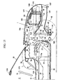
- Ein Fahrzeug, in dem ein Fahrgastraum (2) durch ein Armaturenbrett (3) vom Motorraum (1) getrennt ist, das Folgendes umfasst:einen Windlaufbereich (cowl portion) (27) zum Halten eines vorderen Endes einer Windschutzscheibe (26), der derart oberhalb des Armaturenbretts (3) angeordnet ist, dass er im Wesentlichen in Richtung der Fahrzeugbreite verläuft;ein Instrumententafelteil (30) zur Vergrößerung der Steifheit des Fahrzeugkörpers, das sich derart nach hinten entfernt vom genannten Windlaufbereich (27) befindet, dass es im Wesentlichen in Richtung der Fahrzeugbreite oberhalb des Armaturenbretts (3) verläuft; undeinen vertieften Bereich (3a), der derart ausgebildet ist, dass ein Zwischenbereich, vorzugsweise im Wesentlichen ein mittlerer Bereich des Armaturenbretts (3) in Richtung der Fahrzeugbreite vom genannten Windlaufbereich (27) nach hinten hin zum genannten Instrumententafelteil (30) vertieft ist,wobei die Antriebsvorrichtung (32; 33) für das Fahrzeug derart im genannten vertieften Bereich (3a) angeordnet ist, dass sich die Antriebsvorrichtung (32; 33) vor dem und in der Nähe des genannten Instrumententafelteils (30) befindet.
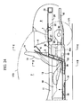
- Das Fahrzeug nach Anspruch 1, wobei die genannte Antriebsvorrichtung (32; 33) einen Motor (32) umfasst, der im Wesentlichen in einer Längsrichtung des Fahrzeugs angeordnet ist, und eine ISG-Einheit (33), die einem hinteren Bereich des Motors (32) nachfolgend verbunden ist.
- Das Fahrzeug nach Anspruch 2, wobei ein Getriebe (34) derart hinter der genannten ISG-Einheit (33) angeordnet ist, dass es der genannten ISG-Einheit (33) nachfolgend in einem Tunnelbereich (10) einer Bodenplatte (4) verbunden ist.
- Das Fahrzeug nach Anspruch 2 oder 3, wobei ein oberes Ende des genannten Motors (32) derart angeordnet ist, dass es sich an einer höheren Position befindet als diejenige einer Sitzfläche eines auf der Bodenplatte (4) angeordneten Fahrgastsitzes (14).
- Das Fahrzeug nach Anspruch 2, 3 oder 4, wobei sich der genannte Motor (32) und die genannte ISG (33) Einheit an einer Stelle befinden, an der sie in Längsrichtung des Fahrzeugs zumindest teilweise mit einem Fahrgast, der auf einem Fahrgastsitz (14) sitzt, überlappen.
- Das Fahrzeug nach einem der vorhergehenden Ansprüche von 2 bis 5, wobei eine Auspuffanlage (35) des Motors (32) derart angeordnet ist, dass sie mittels bzw. bezüglich einem vorderen Bereich einer Seite des genannten Motors (32) verläuft.
- Das Fahrzeug nach einem der vorhergehenden Ansprüche, wobei eine Fahrzeugkörperplatte (65), die zwischen dem genannten Windlaufbereich (27) und einem oberen Ende des genannten Armaturenbretts (3) angeordnet ist, derart ausgebildet ist, dass sie lösbar ist.
- Das Fahrzeug nach Anspruch 7, wobei ein service-Loch (service hole) (64) in einem Bereich zwischen einem Bereich zum Halten des vorderen Endes für die Windschutzscheibe (26) und dem genannten Instrumententafelteil (30) gebildet wird, der dem genannten vertieften Bereich (3a) entspricht, und wobei die genannte Fahrzeugkörperplatte (65) lösbar derart angeordnet ist, dass sie zumindest teilweise das genannte service-Loch (64) bedeckt.
- Das Fahrzeug nach Anspruch 7 oder 8, wobei die genannte Fahrzeugkörperplatte (65) dazu konfiguriert ist, an dem Ort genügend Raum zu bieten, an dem ein Zylinderkopfdeckel (71) des Motors (32) demontierbar ist, wenn er abgenommen werden soll.
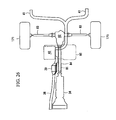
- Die Antriebsvorrichtung für ein Fahrzeug nach einem der vorhergehenden Ansprüche, wobei eine Klimaanlage (8) zur Klimatisierung des Fahrgastraums (2) im Wesentlichen hinter dem Fahrgastraum (2) angeordnet ist.
- Die Antriebsvorrichtung für ein Fahrzeug nach Anspruch 10, wobei ein Laderaum (9) hinter der genannten Klimaanlage (8) gebildet wird.
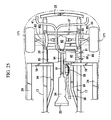
- Die Antriebsvorrichtung für ein Fahrzeug nach einem der vorhergehenden Ansprüche, wobei ein Wärmetauscher (150) zwischen einem vorderen Ende der genannten Antriebsvorrichtung und einer Achse eines Vorderrads (42) eingefügt ist.
- Die Antriebsvorrichtung für ein Fahrzeug nach Anspruch 12, wobei der genannte Wärmetauscher (150) an einem Querträger (44) der Aufhängung montiert ist, die eine Aufhängung (43) für das genannte Vorderrad (42) trägt.
- Die Antriebsvorrichtung für ein Fahrzeug nach Anspruch 13, wobei ein vorderer Bereich der genannten Antriebsvorrichtung am genannten Querträger (cross member) (44) der Aufhängung montiert ist.
- Das Fahrzeug nach Anspruch 13 oder 14, wobei der genannte Querträger (44) der Aufhängung einen Hauptbereich (44A) davon umfasst, der bei Betrachtung von oben im Wesentlichen eine U-Form aufweist, und ein mit dem Hauptbereich (44A) integrales oder einheitliches Querelement (transverse member) (180), das im Wesentlichen in Richtung der Fahrzeugbreite verläuft, und wobei der genannte vordere Bereich der Antriebsvorrichtung auf dem genannten Querelement (180) montiert ist.
- Das Fahrzeug nach Anspruch 13, 14 oder 15, wobei die genannte Antriebsvorrichtung (32; 33) an dem genannten Querträger (44) der Aufhängung an einem oder mehreren Punkten, vorzugsweise an drei unterschiedlichen Punkten montiert ist.
- Das Fahrzeug nach einem der vorhergehenden Ansprüchen in Kombination mit Anspruch 12, wobei ein Luftfilter (160) oberhalb des genannten Wärmetauscher (150) angeordnet ist, wobei ein vertiefter Bereich (160a) an einer unteren Fläche des genannten Luftfilters (160) in einem Bereich gebildet wird, der dem genannten Wärmetauscher (150) entspricht, und wobei sich ein oberer Bereich des genannten Wärmetauscher (150) im genannten vertieften Bereich (160a) des Luftfilters (160) befindet.
- Das Fahrzeug nach einem der vorhergehenden Ansprüche in Kombination mit Anspruch 12 oder 17, wobei ein Aufbewahrungsbereich (98) für einen kleinen Inhalt vor dem genannten Wärmetauscher (150) und/oder dem genannten Luftfilter (160) gebildet wird.
Applications Claiming Priority (4)
| Application Number | Priority Date | Filing Date | Title |
|---|---|---|---|
| JP2003192915A JP4363096B2 (ja) | 2003-07-07 | 2003-07-07 | 車両用駆動装置の配設構造 |
| JP2003192915 | 2003-07-07 | ||
| JP2003271902A JP4363106B2 (ja) | 2003-07-08 | 2003-07-08 | 車両エンジンルーム内の補機配設構造 |
| JP2003271902 | 2003-07-08 |
Publications (3)
| Publication Number | Publication Date |
|---|---|
| EP1495896A2 EP1495896A2 (de) | 2005-01-12 |
| EP1495896A3 EP1495896A3 (de) | 2005-06-29 |
| EP1495896B1 true EP1495896B1 (de) | 2011-06-15 |
Family
ID=33455600
Family Applications (1)
| Application Number | Title | Priority Date | Filing Date |
|---|---|---|---|
| EP04014901A Expired - Fee Related EP1495896B1 (de) | 2003-07-07 | 2004-06-24 | Anordnung einer Antriebseinheit eines Kraftfahrzeugs |
Country Status (2)
| Country | Link |
|---|---|
| US (1) | US7185725B2 (de) |
| EP (1) | EP1495896B1 (de) |
Families Citing this family (28)
| Publication number | Priority date | Publication date | Assignee | Title |
|---|---|---|---|---|
| US20060220405A1 (en) | 2005-03-31 | 2006-10-05 | Mazda Motor Corporation | Structure for arrangement of engine-associated vehicle components |
| JP4663464B2 (ja) * | 2005-09-22 | 2011-04-06 | 本田技研工業株式会社 | 蓄電装置搭載車両 |
| JP4872586B2 (ja) * | 2005-11-10 | 2012-02-08 | 日産自動車株式会社 | 車体前部構造および連結部材 |
| DE102007019407A1 (de) * | 2006-04-25 | 2007-11-08 | Behr America, Inc., Webberville | Gehäuse für ein Heizungs- und/oder Klimaanlagenmodul und Verfahren zur Herstellung eines solchen Gehäuses |
| US8827028B2 (en) * | 2006-07-28 | 2014-09-09 | Polaris Industries Inc. | Side-by-side ATV |
| US7819220B2 (en) * | 2006-07-28 | 2010-10-26 | Polaris Industries Inc. | Side-by-side ATV |
| US20090313904A1 (en) * | 2009-02-04 | 2009-12-24 | Andrew Kerr | Mechanical access door for passenger bus |
| WO2010097890A1 (ja) * | 2009-02-24 | 2010-09-02 | トヨタ自動車株式会社 | 車両前部構造 |
| US8714295B2 (en) * | 2010-01-15 | 2014-05-06 | GM Global Technology Operations LLC | Internal combustion engine and vehicle packaging for same |
| US8943797B2 (en) | 2010-01-15 | 2015-02-03 | GM Global Technology Operations LLC | Cylinder head with symmetric intake and exhaust passages |
| US9103305B2 (en) * | 2010-01-15 | 2015-08-11 | GM Global Technology Operations LLC | Internal combustion engine |
| US8528510B2 (en) * | 2010-01-15 | 2013-09-10 | GM Global Technology Operations LLC | Intake manifold |
| DE102010018481A1 (de) * | 2010-04-28 | 2011-11-03 | Gm Global Technology Operations Llc (N.D.Ges.D. Staates Delaware) | Bodenstruktur einer Kraftfahrzeugkarosserie |
| JP5067502B2 (ja) | 2010-06-03 | 2012-11-07 | トヨタ自動車株式会社 | 冷却風導入構造 |
| US8613335B2 (en) | 2010-08-03 | 2013-12-24 | Polaris Industries Inc. | Side-by-side vehicle |
| US8746719B2 (en) | 2010-08-03 | 2014-06-10 | Polaris Industries Inc. | Side-by-side vehicle |
| DE102011121515B4 (de) * | 2010-12-20 | 2016-06-30 | Mazda Motor Corp. | Batterieanordnungsstruktur eines Fahrzeugs und Verfahren zum Anordnen einer Batterie |
| JP5857655B2 (ja) | 2010-12-27 | 2016-02-10 | マツダ株式会社 | 車両のハーネス配設構造 |
| KR101704955B1 (ko) | 2013-02-20 | 2017-02-08 | 도요타 지도샤(주) | 전기 자동차 |
| JP6060864B2 (ja) * | 2013-09-18 | 2017-01-18 | マツダ株式会社 | 蓄電装置の配設構造 |
| US20160169171A1 (en) * | 2014-12-15 | 2016-06-16 | Ford Global Technologies, Llc. | Modular intake manifold |
| CN113183701A (zh) | 2015-05-15 | 2021-07-30 | 北极星工业有限公司 | 多用途车辆 |
| USD787985S1 (en) | 2015-06-24 | 2017-05-30 | Polaris Industries Inc. | All-terrain vehicle |
| US9649928B2 (en) | 2015-06-25 | 2017-05-16 | Polaris Industries Inc. | All-terrain vehicle |
| US9884647B2 (en) | 2015-12-10 | 2018-02-06 | Polaris Industries Inc. | Utility vehicle |
| JP6922763B2 (ja) * | 2018-01-30 | 2021-08-18 | トヨタ自動車株式会社 | 車両下部構造 |
| US10946736B2 (en) | 2018-06-05 | 2021-03-16 | Polaris Industries Inc. | All-terrain vehicle |
| US11505143B2 (en) * | 2019-02-27 | 2022-11-22 | Ford Global Technologies, Llc | Supercapacitor mounting assemblies and vehicle mounting locations |
Family Cites Families (27)
| Publication number | Priority date | Publication date | Assignee | Title |
|---|---|---|---|---|
| DE295848C (de) | ||||
| US1934385A (en) | 1928-06-18 | 1933-11-07 | Joseph B Strauss | Vehicle |
| US2172831A (en) * | 1938-05-03 | 1939-09-12 | Carlson Philip | Truck body |
| GB694095A (en) | 1949-02-17 | 1953-07-15 | Bristol Aeroplane Co Ltd | Improvements in or relating to motor road vehicles |
| US2817557A (en) * | 1950-01-25 | 1957-12-24 | Chrysler Corp | Unitary body and frame structure for automobiles |
| US2771750A (en) | 1954-04-12 | 1956-11-27 | Houdaille Industries Inc | Package air conditioning unit for automotive vehicle |
| US2867996A (en) | 1955-09-01 | 1959-01-13 | George P Bullard | Cooling means for vehicle motors |
| US2989854A (en) | 1960-03-28 | 1961-06-27 | Gen Motors Corp | Vehicle refrigeration |
| US3827525A (en) * | 1972-05-24 | 1974-08-06 | Gen Motors Corp | Energy absorbing construction for front-engined motor vehicles |
| AT354863B (de) * | 1975-06-13 | 1980-02-11 | List Hans | Kraftfahrzeug mit einer schalldaemmenden kapsel fuer den motor bzw. die motor-getriebe -einheit |
| JPS56161814U (de) * | 1980-05-06 | 1981-12-02 | ||
| US4723810A (en) | 1984-06-18 | 1988-02-09 | Mazda Motor Corporation | Underbody structure for vehicle |
| US4730870A (en) | 1986-03-14 | 1988-03-15 | American Motors Corporation | Modular vehicle construction and assembly method |
| US4988144A (en) * | 1990-01-16 | 1991-01-29 | General Motors Corporation | Plenum and wiper module removable for engine service |
| JP3144094B2 (ja) | 1991-11-13 | 2001-03-07 | 株式会社デンソー | 車両用空気調和装置 |
| US5327988A (en) * | 1992-09-22 | 1994-07-12 | Hme, Inc. | Truck having cab with full access engine enclosure |
| JPH06239147A (ja) | 1993-02-12 | 1994-08-30 | Mazda Motor Corp | 自動車の前部構造 |
| US5511842A (en) | 1993-10-06 | 1996-04-30 | Dillon; John A. | Security vehicle system |
| JP3596554B2 (ja) | 1994-08-18 | 2004-12-02 | 本田技研工業株式会社 | インストルメントパネルの取付構造 |
| JPH0939837A (ja) | 1995-07-27 | 1997-02-10 | Toyota Auto Body Co Ltd | 車両のダッシュパネル構造 |
| DE19654370C8 (de) | 1996-12-24 | 2013-03-28 | JK Patentportfolio GmbH & Co. Echo KG | Heizsystem für Fahrzeuge |
| JP3744121B2 (ja) | 1997-05-27 | 2006-02-08 | 株式会社デンソー | 車両用空調装置 |
| FR2798323B1 (fr) | 1999-09-10 | 2002-01-18 | Valeo Climatisation | Dispositif de chauffage et/ou climatisation de vehicule automobile avec pulseur perfectionne |
| JP3977556B2 (ja) | 1999-10-14 | 2007-09-19 | カルソニックカンセイ株式会社 | 車両用空気調和ユニット |
| DE10054008B4 (de) | 2000-11-01 | 2004-07-08 | Daimlerchrysler Ag | Kraftwagensitz |
| US6445982B1 (en) * | 2001-03-26 | 2002-09-03 | Visteon Global Technologies, Inc. | Regenerative deceleration for a hybrid drive system |
| US6663170B1 (en) * | 2002-07-18 | 2003-12-16 | Volvo Trucks North America | Two piece engine access cover assembly |
-
2004
- 2004-06-09 US US10/863,272 patent/US7185725B2/en active Active
- 2004-06-24 EP EP04014901A patent/EP1495896B1/de not_active Expired - Fee Related
Also Published As
| Publication number | Publication date |
|---|---|
| US7185725B2 (en) | 2007-03-06 |
| US20050006168A1 (en) | 2005-01-13 |
| EP1495896A2 (de) | 2005-01-12 |
| EP1495896A3 (de) | 2005-06-29 |
Similar Documents
| Publication | Publication Date | Title |
|---|---|---|
| EP1495896B1 (de) | Anordnung einer Antriebseinheit eines Kraftfahrzeugs | |
| JP5018961B2 (ja) | 車両前部構造 | |
| JP4637504B2 (ja) | 高圧電装ケースの配設構造 | |
| JP4701916B2 (ja) | 自動車のバッテリ搭載構造 | |
| JP4756333B2 (ja) | 自動車のバッテリ搭載構造 | |
| JP5223453B2 (ja) | 内燃機関搭載の電気自動車 | |
| JP4363106B2 (ja) | 車両エンジンルーム内の補機配設構造 | |
| US20050011640A1 (en) | Air conditioner for vehicle | |
| JP2008155828A (ja) | 車体構造 | |
| JP4756332B2 (ja) | 自動車のバッテリ搭載構造 | |
| JP2005028911A (ja) | 車両エンジンルーム内の補機配設構造 | |
| JP2003326981A (ja) | 車両のエンジン配設構造 | |
| JP2001105893A (ja) | 電気自動車 | |
| JP4103455B2 (ja) | 車両の前部車体構造 | |
| JP5402827B2 (ja) | 冷却風導入構造 | |
| JP2005029103A (ja) | 車両の車体構造 | |
| JP4140272B2 (ja) | 車両のエンジンルーム内の配設構造 | |
| JP4314914B2 (ja) | 車両用補機の配設構造 | |
| JP4363096B2 (ja) | 車両用駆動装置の配設構造 | |
| JP5470732B2 (ja) | 車両のパワートレイン配設構造 | |
| JP2009226974A (ja) | 車両のパワートレイン配設構造 | |
| JP5200612B2 (ja) | 車両のパワートレイン配設構造 | |
| EP1502781A2 (de) | Klimaanlage und ihre Verwendung bei einem Kraftfahrzeug | |
| JP2009234418A (ja) | 車両のパワートレイン配設構造 | |
| JP3477788B2 (ja) | 車両のエンジン補機配設構造 |
Legal Events
| Date | Code | Title | Description |
|---|---|---|---|
| PUAI | Public reference made under article 153(3) epc to a published international application that has entered the european phase |
Free format text: ORIGINAL CODE: 0009012 |
|
| AK | Designated contracting states |
Kind code of ref document: A2 Designated state(s): AT BE BG CH CY CZ DE DK EE ES FI FR GB GR HU IE IT LI LU MC NL PL PT RO SE SI SK TR |
|
| AX | Request for extension of the european patent |
Extension state: AL HR LT LV MK |
|
| PUAL | Search report despatched |
Free format text: ORIGINAL CODE: 0009013 |
|
| RIC1 | Information provided on ipc code assigned before grant |
Ipc: 7B 60K 5/02 A Ipc: 7B 62D 25/08 B Ipc: 7B 60H 1/00 B Ipc: 7B 60K 11/04 B |
|
| AK | Designated contracting states |
Kind code of ref document: A3 Designated state(s): AT BE BG CH CY CZ DE DK EE ES FI FR GB GR HU IE IT LI LU MC NL PL PT RO SE SI SK TR |
|
| AX | Request for extension of the european patent |
Extension state: AL HR LT LV MK |
|
| 17P | Request for examination filed |
Effective date: 20051027 |
|
| AKX | Designation fees paid |
Designated state(s): DE |
|
| GRAC | Information related to communication of intention to grant a patent modified |
Free format text: ORIGINAL CODE: EPIDOSCIGR1 |
|
| GRAP | Despatch of communication of intention to grant a patent |
Free format text: ORIGINAL CODE: EPIDOSNIGR1 |
|
| GRAS | Grant fee paid |
Free format text: ORIGINAL CODE: EPIDOSNIGR3 |
|
| GRAA | (expected) grant |
Free format text: ORIGINAL CODE: 0009210 |
|
| AK | Designated contracting states |
Kind code of ref document: B1 Designated state(s): DE |
|
| REG | Reference to a national code |
Ref country code: DE Ref legal event code: R096 Ref document number: 602004033031 Country of ref document: DE Effective date: 20110721 |
|
| REG | Reference to a national code |
Ref country code: DE Ref legal event code: R084 Ref document number: 602004033031 Country of ref document: DE Effective date: 20111017 |
|
| PLBE | No opposition filed within time limit |
Free format text: ORIGINAL CODE: 0009261 |
|
| STAA | Information on the status of an ep patent application or granted ep patent |
Free format text: STATUS: NO OPPOSITION FILED WITHIN TIME LIMIT |
|
| 26N | No opposition filed |
Effective date: 20120316 |
|
| REG | Reference to a national code |
Ref country code: DE Ref legal event code: R097 Ref document number: 602004033031 Country of ref document: DE Effective date: 20120316 |
|
| PGFP | Annual fee paid to national office [announced via postgrant information from national office to epo] |
Ref country code: DE Payment date: 20200609 Year of fee payment: 17 |
|
| REG | Reference to a national code |
Ref country code: DE Ref legal event code: R119 Ref document number: 602004033031 Country of ref document: DE |
|
| PG25 | Lapsed in a contracting state [announced via postgrant information from national office to epo] |
Ref country code: DE Free format text: LAPSE BECAUSE OF NON-PAYMENT OF DUE FEES Effective date: 20220101 |