EP1495896B1 - Structure d'arrangement d'une unité d'entraînement pour véhicule automobile - Google Patents
Structure d'arrangement d'une unité d'entraînement pour véhicule automobile Download PDFInfo
- Publication number
- EP1495896B1 EP1495896B1 EP04014901A EP04014901A EP1495896B1 EP 1495896 B1 EP1495896 B1 EP 1495896B1 EP 04014901 A EP04014901 A EP 04014901A EP 04014901 A EP04014901 A EP 04014901A EP 1495896 B1 EP1495896 B1 EP 1495896B1
- Authority
- EP
- European Patent Office
- Prior art keywords
- vehicle
- engine
- driving device
- disposed
- panel
- Prior art date
- Legal status (The legal status is an assumption and is not a legal conclusion. Google has not performed a legal analysis and makes no representation as to the accuracy of the status listed.)
- Expired - Fee Related
Links
Images


Classifications
-
- B—PERFORMING OPERATIONS; TRANSPORTING
- B60—VEHICLES IN GENERAL
- B60H—ARRANGEMENTS OF HEATING, COOLING, VENTILATING OR OTHER AIR-TREATING DEVICES SPECIALLY ADAPTED FOR PASSENGER OR GOODS SPACES OF VEHICLES
- B60H1/00—Heating, cooling or ventilating [HVAC] devices
- B60H1/24—Devices purely for ventilating or where the heating or cooling is irrelevant
- B60H1/241—Devices purely for ventilating or where the heating or cooling is irrelevant characterised by the location of ventilation devices in the vehicle
- B60H1/242—Devices purely for ventilating or where the heating or cooling is irrelevant characterised by the location of ventilation devices in the vehicle located in the front area
-
- B—PERFORMING OPERATIONS; TRANSPORTING
- B60—VEHICLES IN GENERAL
- B60H—ARRANGEMENTS OF HEATING, COOLING, VENTILATING OR OTHER AIR-TREATING DEVICES SPECIALLY ADAPTED FOR PASSENGER OR GOODS SPACES OF VEHICLES
- B60H1/00—Heating, cooling or ventilating [HVAC] devices
- B60H1/00007—Combined heating, ventilating, or cooling devices
- B60H1/00207—Combined heating, ventilating, or cooling devices characterised by the position of the HVAC devices with respect to the passenger compartment
-
- B—PERFORMING OPERATIONS; TRANSPORTING
- B60—VEHICLES IN GENERAL
- B60H—ARRANGEMENTS OF HEATING, COOLING, VENTILATING OR OTHER AIR-TREATING DEVICES SPECIALLY ADAPTED FOR PASSENGER OR GOODS SPACES OF VEHICLES
- B60H1/00—Heating, cooling or ventilating [HVAC] devices
- B60H1/00271—HVAC devices specially adapted for particular vehicle parts or components and being connected to the vehicle HVAC unit
-
- B—PERFORMING OPERATIONS; TRANSPORTING
- B60—VEHICLES IN GENERAL
- B60H—ARRANGEMENTS OF HEATING, COOLING, VENTILATING OR OTHER AIR-TREATING DEVICES SPECIALLY ADAPTED FOR PASSENGER OR GOODS SPACES OF VEHICLES
- B60H1/00—Heating, cooling or ventilating [HVAC] devices
- B60H1/00357—Air-conditioning arrangements specially adapted for particular vehicles
-
- B—PERFORMING OPERATIONS; TRANSPORTING
- B60—VEHICLES IN GENERAL
- B60H—ARRANGEMENTS OF HEATING, COOLING, VENTILATING OR OTHER AIR-TREATING DEVICES SPECIALLY ADAPTED FOR PASSENGER OR GOODS SPACES OF VEHICLES
- B60H1/00—Heating, cooling or ventilating [HVAC] devices
- B60H1/24—Devices purely for ventilating or where the heating or cooling is irrelevant
- B60H1/247—Disposition of several air-diffusers in a vehicle for ventilation-air circulation in a vehicle cabin
-
- B—PERFORMING OPERATIONS; TRANSPORTING
- B60—VEHICLES IN GENERAL
- B60K—ARRANGEMENT OR MOUNTING OF PROPULSION UNITS OR OF TRANSMISSIONS IN VEHICLES; ARRANGEMENT OR MOUNTING OF PLURAL DIVERSE PRIME-MOVERS IN VEHICLES; AUXILIARY DRIVES FOR VEHICLES; INSTRUMENTATION OR DASHBOARDS FOR VEHICLES; ARRANGEMENTS IN CONNECTION WITH COOLING, AIR INTAKE, GAS EXHAUST OR FUEL SUPPLY OF PROPULSION UNITS IN VEHICLES
- B60K15/00—Arrangement in connection with fuel supply of combustion engines or other fuel consuming energy converters, e.g. fuel cells; Mounting or construction of fuel tanks
- B60K15/03—Fuel tanks
- B60K15/063—Arrangement of tanks
- B60K15/067—Mounting of tanks
-
- B—PERFORMING OPERATIONS; TRANSPORTING
- B60—VEHICLES IN GENERAL
- B60K—ARRANGEMENT OR MOUNTING OF PROPULSION UNITS OR OF TRANSMISSIONS IN VEHICLES; ARRANGEMENT OR MOUNTING OF PLURAL DIVERSE PRIME-MOVERS IN VEHICLES; AUXILIARY DRIVES FOR VEHICLES; INSTRUMENTATION OR DASHBOARDS FOR VEHICLES; ARRANGEMENTS IN CONNECTION WITH COOLING, AIR INTAKE, GAS EXHAUST OR FUEL SUPPLY OF PROPULSION UNITS IN VEHICLES
- B60K15/00—Arrangement in connection with fuel supply of combustion engines or other fuel consuming energy converters, e.g. fuel cells; Mounting or construction of fuel tanks
- B60K15/03—Fuel tanks
- B60K15/073—Tank construction specially adapted to the vehicle
-
- B—PERFORMING OPERATIONS; TRANSPORTING
- B60—VEHICLES IN GENERAL
- B60K—ARRANGEMENT OR MOUNTING OF PROPULSION UNITS OR OF TRANSMISSIONS IN VEHICLES; ARRANGEMENT OR MOUNTING OF PLURAL DIVERSE PRIME-MOVERS IN VEHICLES; AUXILIARY DRIVES FOR VEHICLES; INSTRUMENTATION OR DASHBOARDS FOR VEHICLES; ARRANGEMENTS IN CONNECTION WITH COOLING, AIR INTAKE, GAS EXHAUST OR FUEL SUPPLY OF PROPULSION UNITS IN VEHICLES
- B60K5/00—Arrangement or mounting of internal-combustion or jet-propulsion units
- B60K5/02—Arrangement or mounting of internal-combustion or jet-propulsion units with the engine main axis, e.g. crankshaft axis, substantially in or parallel to the longitudinal centre line of the vehicle
-
- B—PERFORMING OPERATIONS; TRANSPORTING
- B62—LAND VEHICLES FOR TRAVELLING OTHERWISE THAN ON RAILS
- B62D—MOTOR VEHICLES; TRAILERS
- B62D25/00—Superstructure or monocoque structure sub-units; Parts or details thereof not otherwise provided for
- B62D25/08—Front or rear portions
- B62D25/081—Cowls
-
- B—PERFORMING OPERATIONS; TRANSPORTING
- B62—LAND VEHICLES FOR TRAVELLING OTHERWISE THAN ON RAILS
- B62D—MOTOR VEHICLES; TRAILERS
- B62D25/00—Superstructure or monocoque structure sub-units; Parts or details thereof not otherwise provided for
- B62D25/08—Front or rear portions
- B62D25/082—Engine compartments
Definitions
- the present invention relates to a vehicle in which a passenger compartment is separated by a dash panel from an engine room.
- FIG. 29 that is a conventional structure of a FR (front-engine rear-drive) type, in which there are provided a passenger compartment 191 which is separated by a dash panel 192 from an engine room 193 and located in front of the passenger compartment 191 and rear wheels (not shown) are driven by an engine 194 disposed in a longitudinal direction of the vehicle in the engine room 193.
- reference numerals 195, 196 and 197 denote a pair of front side frame, a cooler condenser and a radiator, respectively.
- This conventional structure has a problem that since the engine 194 having its heavy weight is disposed in the engine room 193 which is located forward away from a center of the vehicle, its yaw inertia moment is relatively large.
- These air conditioning units enable the engine located forward to be moved back to some extent toward the center of the vehicle, so that the maneuverability of the vehicle can be improved to certain degree due to a reduced yaw inertia moment.
- JP-A-09-039837 discloses a dash panel structure of vehicle comprising a centre dash part having a first panel forming an upper surface of the centre dash part and a pair of third panels extending from the centre dash part in a vehicle widthwise direction.
- EP-A-1 245 422 discloses a regenerative deceleration for a hybrid drive system in which a control preferentially applies torque from an integrated starter-generator over a compression torque from an engine so as to achieve a desired deceleration torque.
- the present invention has been devised in view of the above-mentioned problems, and an object of the present invention is to improve maneuverability and stability of a vehicle and dynamic performance of the vehicle by reducing a yaw inertia moment.
- the present invention provides a vehicle, in which a passenger compartment is separated by a dash panel from an engine room, comprising a cowl portion for supporting a front end of a windshield that is disposed above the dash panel so as to extend substantially in a width direction of the vehicle, an instrument panel member for increasing the rigidity of the vehicle body that is located backward away from the cowl portion so as to extend substantially in the width direction of the vehicle above the dash panel, and a recess portion that is formed in such manner that an intermediate portion, preferably substantially a central portion of the dash panel in the width direction of the vehicle is recessed backward from the cowl portion to the instrument panel member, wherein the driving device for the vehicle is disposed in the recess portion such that the driving device is located in front of and close to or in proximity of or adjacent to the instrument panel member.
- the layout of the air conditioning unit can be compatible with forming the load compartment.
- a heat exchanger is interposed between a front end of the driving device and an axle of a front wheel.
- the heavy articles of the driving device and the heat exchanger can be moved back toward the center of the vehicle, the yaw inertia moment can be reduced further, thereby improving maneuverability and stability of the vehicle and dynamic performance of the vehicle.
- the heat exchanger is mounted on a suspension cross member supporting a suspension for the front wheel.
- a support of the heat exchanger can be provided effectively by making use of an existing member, namely the suspension cross member. Further, since rigidity of the suspension cross member is high, a high-rigidity support of the heat exchanger can be maintained.
- a front portion of the driving device is mounted on the suspension cross member.
- a pitching (a front/rear end's movement in a vertical direction) of the driving device can be prevented by mounting the front end of the driving device on the suspension cross member.
- the suspension cross member comprises a main portion thereof with a substantially U-shaped figure when viewed from above and a transverse member integral or unitary with the main portion and extending substantially in the width direction of the vehicle, and the front portion of the driving device is mounted on the transverse member.
- mounting of the front end of the driving device can be provided effectively by making use of the transverse member (existing member) located in the best position.
- the driving device is mounted on the suspension cross member at one or more points, preferably at three different points.
- the pitching of the driving device can be prevented more efficiently.
- an air cleaner is disposed above the heat exchanger, a recess portion is formed on a lower face of the air cleaner at a portion which corresponds to the heat exchanger, and an upper portion of the heat exchanger is located in the recess portion of the air cleaner.
- the air cleaner with an enough volume can be provided, reducing the vehicle height properly. Further, the air cleaner as a heavy article can also be moved back as much as possible, by providing the above-described recess portion.
- the small load can be kept in the storage portion, thereby improving facility.
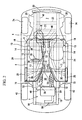
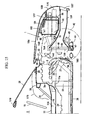
- FIGS. 1 through 9 show a layout structure of a driving device for a vehicle.
- an engine room or compartment 1 is separated by a dash lower panel 3 (dash panel) from a passenger compartment 2 in a longitudinal direction of the vehicle.
- a floor panel 4 is subsequently connected to a lower end portion of the dash lower panel 3 to extend backward in a substantially horizontal direction.
- a bulkhead 5 is provided so as to rise up slantingly from a rear portion of the floor panel 4 , at a back face of an upper end portion of which there is provided a rear cowl portion 6 extending substantially in a width direction of the vehicle.
- the rear bulkhead 5 is a panel member which separates the passenger compartment 2 from a rear part compartment.
- a rear floor 7 is provided to extend backward from an intermediate portion, preferably a middle portion of the bulkhead 5 substantially in a vertical direction of the vehicle.
- An air conditioning unit 8 for air-conditioning the passenger compartment 2 is provided near the rear cowl portion 6 on the rear floor 7 , and a load compartment 9 (so-called trunk room) is formed behind the air conditioning unit 8 and/or the rear cowl portion 6 .
- a tunnel portion 10 which protrudes in the passenger compartment 2 and extends substantially in the vehicle longitudinal direction.
- a tunnel member 11 (so-called high-mount-backbone frame) is fixed on an upper portion of the tunnel portion 10.
- the tunnel member 11 is connected to the dash lower panel 3 at its front end and to the bulkhead 5 at its rear end.
- a closed cross section extending in the vehicle longitudinal direction is formed by the tunnel member 11 and the tunnel portion 10.
- left and right seats 14, 14 on the floor panel 4 with the above-described tunnel portion 10 and tunnel member 11 between them, which include seat cushions 12, 12 and seat backs 13, 13 respectively.
- the right seat 14 corresponding to a steering wheel 15 is a driver's seat
- the left seat 14 is a passenger's seat.
- a kick-up portion of each rear portion of the front side frames 16, 16 is provided along the dash lower panel 3
- a pair of left and right floor frames 17, 17 which are coupled to respective lower ends of the kick-up portions and extend substantially in the vehicle longitudinal direction.
- an upper end of the engine 32 is disposed so as to be located in a higher position than that of a sitting face of the passenger seat 14 disposed on the floor panel 4 , and the engine 32 , the ISG unit 33 and the transmission 34 are located in a position where these are at least partly overlapped with a passenger A sitting on the passenger seat 14 in the vehicle longitudinal direction. Accordingly, a height and a length of the entire vehicle are reduced as much as possible so as to provide a compact vehicle.
- an exhaust system is coupled to an exhaust side of a cylinder head of the engine 32 , which comprises an exhaust manifold 35 extending forward at one side of the engine 32 from the cylinder head.
- a first exhaust pipe 36 is provided to extend from a gathering portion of the exhaust manifold 35 located at the one side of the engine 32 in the substantially vertical direction, and a catalyst 37 (so-called adjacent catalyst) is disposed in the first exhaust pipe 36.
- a second exhaust pipe 38 located downstream of the first exhaust pipe 36 is disposed in the tunnel portion 10 , and a catalyst 39, a silencer 40 and a bifurcate exhaust pipe 41 are coupled to downstream portions of the second exhaust pipe 38 (see FIG. 2 ).
- the exhaust system of the engine 32 is comprised of the above-described parts 35 though 41 , which is disposed so as to extend by way of a front portion of the one side of the engine 32. Accordingly, even if a layout space for the gathering portion of the exhaust system becomes small due to the moved-back layout of the engine 32 , the disposition of the exhaust manifold 35 and its gathering portion can be achieved surely by making use of this space effectively.
- front wheels 42, 42 are supported by a pair of suspension arms 43, 43, and lower arms of the suspension arms 43, 43 are mounted on the suspension cross member 44.
- the front wheels 42, 42 are steered by a steering rack 45 and left-and-right tie rods 46, 46.
- a cooling unit 48 is supported on the suspension cross member 44 through a bracket 47, and a condenser for air conditioning, so-called cooler condenser 49 is disposed in front of the cooling unit 48.
- a bonnet 50 covering an upper portion of the engine room 1 , and a front grille 52 having an opening 51 for a travelling air intake is formed in front of and/or below the bonnet 50 .
- the opening 51 and a front face of the cooling unit 48 are coupled by a duct 53 .
- an air cleaner 54 is disposed above the duct 53 and the cooling unit 48 in the engine room 1.
- An intake pipe 55 is attached at a portion upstream of the air cleaner 54
- an intake pipe 56 and an intake manifold 57 are attached to a downstream portion of the air cleaner 54 . Accordingly, an air which has been filtered by an element of the air cleaner 54 (see FIG. 3 ) is supplied into intake ports formed at the cylinder head of the engine 32 through the intake pipe 56 and the intake manifold 57 .
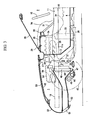
- FIG. 6 is an enlarged side view of a main part of FIG. 3 , and a vehicle body panel disposed between the cowl portion 27 and an upper end of the dash lower panel 3 is formed so as to be detachable.
- the cowl upper 28 constituting a part of the cowl portion 27 is formed so as to be detachable.
- nuts 60...60 are fixed by welding at plural portions at a lower face of a front portion of the cowl box 29 which corresponds to a bent portion 28a of the cowl upper 28 which is located at a side of the cowl box 29 .
- the cowl upper 28 as the vehicle body panel is attached to the cowl box 29.
- the bonnet 50 is opened and then the bolts 61...61 are unfastened and removed. Accordingly, the cowl upper 28 is detached from the cowl box 29 and the dash lower panel 3.
- the front portion of the cowl upper 28 is located forward with respect to an upper-end bent portion 3b of the dash lower panel 3 , and a sealing member 63 for sealing the lower face of the bonnet 50 is attached at an upper end of front portion of the cowl upper 28 so that a gap between a reinforcement 62 and the front portion of the cowl upper 28 can be sealed up.
- a service hole 64 is formed between the cowl box 29 functioning as the front supporting portion for windshield 26 and an upper-end bent portion 3c of the recess portion 3a which is located adjacent to the instrument panel member 30 in such manner that it is located at a portion corresponding to the recess portion 3a.
- a service hole cover 65 disposed as a vehicle body panel which detachably at least partly covers the service hole 64 .
- nuts 66..., 67. .. are fixed preferably by welding at plural portions at a lower face of the cowl box 29 and a lower face of the upper-end bent portion 3c of the recess portion 3a .
- the service hole cover 65 is to be attached to the cowl box 29 and the upper-end bent portion 3c of the recess portion 3a .
- the service hole cover 65 is detached from an opening edge of the service hole 64 by unfastening the bolts 68..., 69....
- the present embodiment provides the layout structure of the driving device for the vehicle, in which the passenger compartment 2 is separated by the dash lower panel 3 from the engine room 1 , comprising the cowl portion 27 for supporting the front end of the windshield 26 that is disposed above the dash lower panel 3 so as to extend substantially in the vehicle width direction, the instrument panel member 30 that is located backward away from the cowl portion 27 so as to extend substantially in the vehicle width direction above the dash lower panel 3 , and the recess portion 3a that is formed in such manner that the central portion of the dash lower panel 3 in the vehicle width direction is recessed backward from the cowl portion 27 to the instrument panel member 30 , wherein the driving device (engine 32 ) is disposed in the recess portion 3a such that the driving device (engine 32 ) is located in front of and close to or in proximity of the instrument panel member 30.
- the recess portion 3a is formed in such manner that part of the dash lower panel 3 is recessed backward from the cowl portion 27 to the instrument panel member 30 located backward away from the cowl portion 27 and the driving device (see the engine 32 ) is disposed in the recess portion 3a , the moved-back layout of the driving device having a heavy weight can be achieved, thereby improving maneuverability and stability of the vehicle and dynamic performance of the vehicle due to the reduced yaw inertia moment and also increasing rigidity of the vehicle body due to the large-scale instrument panel member 30.
- the driving device comprises the engine 32 preferably disposed substantially in the vehicle longitudinal direction and the ISG unit 33 connected subsequently to the rear portion of the engine 32.
- the ISG unit 33 behind the engine 32 may increase a length of the driving device in the vehicle longitudinal direction, it can be achieved to lay out the heavy article close to the center of the vehicle regardless of the increased length, thereby improving maneuverability and stability of the vehicle and dynamic performance of the vehicle due to the reduced yaw inertia moment.
- the transmission 34 is disposed behind the engine 32 and/or the ISG unit 33 so as to be connected subsequently to the ISG unit 33 in the tunnel portion 10 of the floor panel 4 . According to this structure, the transmission 34 can be also laid out closer or close to the center in the vehicle longitudinal direction.
- the upper end of the engine 32 is disposed so as to be located in a higher position than that of the sitting face of the passenger seat 14 disposed on the floor panel 4. According to this structure, the moved-back layout of the heavy articles or the mass center of the engine 32 and the ISG unit 33 can be achieved, providing a low vehicle-height by locating the upper end of the engine 32 in the higher position than that of the sitting face of the seat 14.
- the engine 32 , the ISG unit 33 and the transmission 34 are located in a position where these are at least partly overlapped with the passenger A (see FIG. 5 ) sitting on the passenger seat 14 in the vehicle longitudinal direction.
- the length of the vehicle can be short, maintaining an enough space for the passenger in the passenger compartment, and the moved-back layout of the engine 32 can be achieved.
- the vehicle body panel (see the cowl upper panel 28 ) disposed between the cowl portion 27 and the upper end of the dash lower panel 3 is formed so as to be detachable. According to this structure, the function of services can be improved by the detachable structure of at least part of the vehicle body panel.
- the service hole 64 is formed at a portion between the front end supporting portion (see the cowl box 29 ) for the windshield 26 and the instrument panel member 30 which at least partly corresponds to the recess portion 3a , and the vehicle body panel (see the service hole cover 65 ) is disposed detachably to at least partly cover the service hole 64. According to this structure, the function of services can be improved by the detachable structure of the vehicle body panel.
- the vehicle body panel (see the cowl upper 28 and/or service hole cover 65 ) is configured so as to provide an enough space where the cylinder head cover 71 of the engine 32 is removable while it is detached. According to this structure, since the cylinder head cover 71 of the engine 32 is able to be removed, the function of services can be maintained, achieving the moved-back layout of the engine 32.
- the exhaust system (see the exhaust manifold 35 particularly) of the engine 32 is disposed so as to extend by way of the front portion of the one side of the engine 32 .
- the engine exhaust system, especially the exhaust manifold 35 at least partly extends in front of the engine once, a proper layout of the exhaust system can be achieved by making use of a space effectively.
- the moved-back layout of the heavy article is aimed by providing the engine 32 at least partly extending in the vehicle longitudinal direction in the recess portion 3a of the dash lower panel 3 , there may remain only a relatively small layout space for the exhaust system.
- the proper layout of the exhaust system can be achieved by making use of a space effectively, by configuring the exhaust manifold 35 with a relatively large volume for the purpose of a high exhaust efficient so as to at least partly extend in front of the engine 32 once.
- the air conditioning unit 8 for air-conditioning the passenger compartment 2 is disposed preferably behind the passenger compartment 2 . According to this structure, since the air conditioning unit 8 is preferably disposed behind the passenger compartment 2 , namely in the back portion of the vehicle, the moved-back layout of the driving device can be achieved surely.
- the dash panel is preferably embodied by the dash lower panel 3
- the vehicle body panel is preferably embodied by the cowl upper 28 (specifically, cowl upper panel) and/or the service hole cover 65
- the front end supporting portion for the windshield is preferably embodied by the cowl box 29 .
- the invention is not limited to this embodiment.
- This embodiment comprises a structure in which a heat exchanger is interposed between a front end of the driving device and an axle of the front wheel.
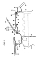
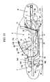
- This structure is shown in FIGS. 10 through 19 , and hereinafter it will be described in detail referring to these drawings.
- FIGS. 10 , 11 , 12 , 14 and 16 correspond respectively to FIG. 1 , 5 , 2 , 3 and 4 )
- a lower portion of a radiator 150 of the cooling unit 48 is supported as shown in a side view of FIG. 17 .
- the bracket 47 with a substantially U-shaped view in the side view is attached to the suspension cross member 44 through connecting means 151 such as bolts and nuts, and a lower tank of the radiator 150 is mounted on an upper face of the bracket 47 through a mount resilient member or rubber 152 .
- an upper end of the radiator 150 is supported as shown in an elevation view of FIG. 18 .
- an upper bracket 154 with a substantially S- or Z-shaped view in the elevation view is attached to the front side frame 16 through connecting means 153 such as bolts and nuts, and a upper tank of the radiator 150 is supported at a lower portion of an inner-side projection of the upper bracket 154 through a mount resilient member or rubber 155 .
- the radiator 150 is disposed, as shown in FIGS. 14 and 15 , between the front end of the engine 32 and an axle of the front wheel 42 , namely within a wheel base.
- an air cleaner 160 is disposed above the air duct 159 and the cooling unit 48 in the engine room 1.
- An intake pipe 161 (so-called fresh air duct) is attached at a portion upstream of the air cleaner 160 , and an air intake hose 162 and an intake manifold 163 are attached to a portion downstream of the air cleaner 160 . Accordingly, an air which has been filtered by an air cleaner element 164 of the air cleaner 160 (see FIG. 14 ) is supplied into intake ports formed at the cylinder head of the engine 32 through the air intake hose 162 and the intake manifold 163.
- the air cleaner 160 includes an air cleaner case 160b , an air cleaner cover 160c , and the air cleaner element 164 (so-called filter) in the air cleaner case 160b, and the above-described recess portion 160a is formed at a side of the air cleaner cover 160 .
- an insulator 97 for protecting from a heat is attached over the lower face of the air cleaner case 160b of the air cleaner 160 with a gap 96 so as to at least partly cover a mostly entire area of the lower face.
- a front trunk box 98 as a storage portion for a small load is provided in front of the radiator 150 and the air cleaner 160.
- the front trunk box 98 preferably is of a substantially box shape with a bottom, whose upper portion is open. It also has a flange portion extending outwardly at its upper opening edge which is formed integrally or unitarily therewith.
- a lid member 101 for substantially opening or closing the upper-end opening of the front trunk box 98 is attached to a lower face of the bonnet 156 through a bellows or extensible member 100. Accordingly, the upper-end opening of the front trunk box 98 is made open when the bonnet 156 is opened, while it is made closed when the bonnet 156 is closed.
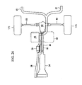
- the trunk pan 99 may be configured, as shown in FIG. 20 , in such manner that at least one, preferably plural portions of the trunk pan 99 in the vehicle width direction are connected with the front cross member 18 through one or more brackets 102, 102 to increase rigidity thereof.
- FIGS. 10 , 12 and 16 there are provided one or more, preferably a pair of batteries 165, 165 at both sides of the engine 32 in front of the general face of the dash lower panel 3 (just in front of the panel 3 in this embodiment).
- heavy articles such as the driving device including the engine 32 and the ISG unit 33 , and auxiliary parts of the batteries 165, 165 and the radiator 150 are all disposed, as shown in FIGS. 12 and 16 , within the wheel base in order to reduce yaw inertia moments thereof.
- the above-described battery 165 is installed as shown in FIG. 21 .
- it has a battery case 167 which is made of synthetic resin and includes a flange portion 166 integral with a lower portion thereof.
- a battery tray 168 preferably made of steel is interposed between a upper frame 16a of the front side frame 16 and the bottom of the battery 165.
- the battery 165 in the battery case 167 is fixed at the front side frame 16 by inserting one or more bolts 169 ... from above of the flange portion 166 into corresponding nuts which has been fixed to a lower face of the upper frame 16a preferably by welding in advance, and fastening them.
- the upper of the battery 165 is covered with a battery cover 170 which should be attached to the battery case 167.
- FIGS. 10 through 21 other reference numerals denote parts respectively as follows: a rear wheel 171 ; a roof 172 for selectively opening or closing an upper of the passenger compartment 2 ; an instrument panel 173 ; a bumper reinforcement 174 attached to the front end of the front side frame 16 through a connecting member 175; an apron reinforcement 176 ; the shroud member 177 ; a front header 178; a front pillar 179; and a transverse member 180 of the suspension cross member 44.
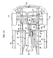
- the above-described suspension cross member 44 comprises a main portion 44A thereof with a substantially U-shaped figure when viewed from above and the transverse member 180 integral or unitary with the main portion 44A and extending substantially in the width direction of the vehicle, and a front portion of the engine 32 as the driving device, specifically a front portion of a cylinder block is mounted on the transverse member 180 through an engine front-mount bracket 103 and an engine mount resilient member or rubber 104.
- both sides of the cylinder block are mounted on at least partly overlapped portions of the transverse member 180 and the suspension cross main portion 44A through engine-side mount brackets 105, 106 and engine mount resilient members or rubbers 107, 108 .
- the front portion of the cylinder block of the engine 32 is mounted on the suspension cross member 44, and the engine 32 is mounted at one or more, e.g. three different points as shown in FIGS. 22 and 23 .
- the above-described rear differential device 82 is a differential device for driving the rear-wheel axles 83, 83, and there is provided a torque tube PPF 84 (PPF means a power plan frame) surrounding the propeller shaft 81 .
- PPF torque tube
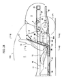
- a fuel tank 85 is disposed at least partly below the trunk room 9 as a load compartment between the above-described rear bulkhead 5 and/or the rear-wheel axle 83 as shown in FIGS. 24 , 25 , 26 and 28 .
- the rear differential device 82 for driving the rear-wheel axles 83, 83 is placed away or substantially behind the fuel tank 85, and thus the fuel tank 85 is prevented from being struck by the rear differential device 82 during the vehicle head-on collision.
- the above-described air conditioning unit 8 is located (preferably on the rear floor 7 behind the rear bulkhead 5) substantially above the fuel tank 85 .
- the fuel tank 85 is provided, as shown in FIG. 28 , with a recess portion 85a at its portion which corresponds to the disposition position of the silencer 40 and the torque tube PPF 84, and the fuel tank 85 is formed so as to have a substantially L-shaped entire view in the elevation view.
- tank mount straps 86, 86 for mounting (hanging and retaining) the fuel tank 85 at the tank's mount portions 85b, 85c.
- An insulator 87 for preventing a heat damage from the exhaust system is interposed between the mount portions 85b, 85c and the tank mount straps 86, 86 , and there is provided a gap 88 between the tank 85 and the insulator 87 preferably substantially covering the substantially entire area of the lower face of the fuel tank 85 .
- part of the exhaust pipes 38, 41 as exhaust pipes and the silencer 40 are disposed. Namely, heavy articles of the silencer 40 and the fuel tank 85 are located within the wheel base, and thus the yaw inertia moment is further reduced.
- the silencer 40 is supported on the rear side frame 20 through one or more mount members 89, 89 preferably at its two points as shown in FIGS. 25 and 28 .
- Each mount member 89 includes a silencer mount bracket 90 fixed at the side of the silencer 40, a lower bracket 92 connecting the silencer mount bracket 90 with a mount resilient member or rubber 91 , and an upper bracket 93 connecting the rear side frame 20 with the mount rubber 91 . Further, in order to prevent the silencer 40 from moving forward to a position in front of the rear differential device 82 during a vehicle rear collision, the silencer 40 and the rear differential device 82 are disposed in such manner that these are at least partly offset from each other in the vehicle width direction, as shown in FIGS. 25 and 26 .
- the exhaust pipes 38, 41 as the exhaust pipes are disposed extending substantially in the vehicle longitudinal direction under the floor panel 4 and below the rear floor 7 as shown in FIGS. 24 , 25 and 26 .
- the passenger seat 14 is placed on the floor panel 4 in the passenger compartment 2 as described above.
- the above-described catalyst 39 interposed between the exhaust pipes 38, 41 is disposed below the seat 14 , specifically in the tunnel portion 10 to protect the passenger on the seat 14 from the heat damage.
- reference numerals 94, 94 denote a pair of lower tunnel members (so-called lower backbone frames) extending substantially in the vehicle longitudinal direction so as to form a closed cross section with the floor panel 4, and SB denotes a seat buckle.
- each rear wheel 171 is suspended independently by a multi-link type of rear suspension RS , and the rear suspension RS is supported on the sub-frame SF .
- the present embodiment shows the structure that the driving device (specifically, the engine 32 ) is disposed in the recess portion 3a of the dash lower panel 3 as shown in FIG. 16 , and at least part of the heat exchanger (see the radiator 150 ), as shown in FIG. 14 , is disposed between the front end of the driving device and the axle of the front wheel 42.
- the driving device specifically, the engine 32
- the radiator 150 is disposed between the front end of the driving device and the axle of the front wheel 42.
- the driving device specifically, the engine 32
- the heat exchanger see radiator 150
- the heavy articles of the driving device and the heat exchanger can be moved back toward the center of the vehicle.
- the yaw inertia moment can be reduced, thereby improving maneuverability and stability of the vehicle and dynamic performance of the vehicle.
- the air cleaner 160 is disposed substantially above the heat exchanger (see radiator 150 ) as shown in FIG. 19 , the recess portion 160a is formed on the lower face of the air cleaner 160 at the portion which corresponds to the heat exchanger, and the upper portion (see upper tank) of the heat exchanger (see radiator 150 ) is located in the recess portion 160a.
- the air cleaner 160 with an enough volume can be provided, reducing the vehicle height properly. Further, the air cleaner 160 as a heavy article can also be moved back as much as possible, by providing the above-described recess portion 160a.
- the front portion of the driving device (see engine 32 ) is mounted on the above-described suspension cross member 44 .
- a pitching (a front/rear end's movement in the vertical direction) of the driving device can be prevented by mounting the front end of the driving device (see engine 32 ) on the suspension cross member 44 .
- the suspension cross member 44 comprises, as shown in FIG. 23 , the main portion 44A with the substantially U-shaped figure when viewed from above and the transverse member 180 integral with the main portion 44A and extending substantially in the width direction of the vehicle, and the front portion of the driving device (see engine 32 ) is mounted on the transverse member 180 .
- mounting of the front end of the driving device (see engine 32 ) can be provided effectively by making use of the transverse member 180 (existing member) located in the best position.
- the driving device (see engine 32 ) is mounted on the suspension cross member 44 preferably at three different points. According to this structure, the pitching of the driving device (see engine 32 ) can be prevented more efficiently.
- the storage portion (see front trunk box 98 ) for a small load is formed in front of the heat exchanger (see radiator 150 ) and/or the air cleaner 160 . According to this structure, the small load can be kept in the storage portion (see front trunk box 98 ), thereby improving facility.
- the load compartment 9 is formed preferably behind the air conditioning unit 8 .
- the layout of the air conditioning unit 8 can be compatible with forming the load compartment 9 .
Claims (18)
- Un véhicule, dans lequel un compartiment passagers (2) est séparé de l'espace moteur (1) par un tablier (3), comprenant :une portion auvent (27) pour soutenir une extrémité frontale d'un pare-brise (26), qui est disposée au-dessus du tablier (3) de manière à s'étendre essentiellement dans une direction de largeur du véhicule ;un élément instrument de bord (30) pour augmenter la rigidité du châssis du véhicule, qui est situé en arrière de façon éloignée de la dite portion d'auvent (27) de manière à s'étendre essentiellement dans la direction de largeur du véhicule au-dessus du tablier (3) ; etune portion cavité (3a) qui est constituée de telle manière qu'une portion intermédiaire, de préférence essentiellement une portion centrale du tablier (3) en direction de largeur du véhicule est en retrait vers l'arrière à partir de la dite portion auvent (27) vers l'élément instrument de bord (30) nommé,sachant que le dispositif d'entraînement (32 ; 33) pour le véhicule est disposé dans la dite portion cavité (3a) de manière que le dispositif d'entraînement (32 ; 33) soit situé devant et à proximité du dit élément instrument de bord (30).
- Le véhicule d'après la revendication 1, pour lequel le dit dispositif d'entraînement (32 ; 33) comprend un moteur (32) disposé essentiellement dans une direction longitudinale du véhicule et une unité ISG (33) connectée à la suite d'une portion arrière du moteur (32).
- Le véhicule d'après la revendication 2, pour lequel une boîte de vitesses (34) est disposée derrière la dite unité ISG (33) de manière à être connectée à la suite de l'unité ISG (33) nommée dans une portion tunnel (10) du plancher (4).
- Le véhicule d'après la revendication 2 ou 3, pour lequel une extrémité supérieure du dit moteur (32) est disposée de manière à être située à un niveau plus élevé que celui d'une surface de l'assise d'un siège passager (14) disposé sur le plancher (4).
- Le véhicule d'après la revendication 2, 3 ou 4, pour lequel le dit moteur (32) et la dite unité ISG (33) sont situés dans une position, dans laquelle ceux-ci se chevauchent dans une direction longitudinale du véhicule avec un passager assis dans le siège passager (14).
- Le véhicule d'après une des revendications de 2 à 5, pour lequel un système d'échappement (35) du moteur (32) est disposé de manière à s'étendre en passant par une portion frontale d'un côté du dit moteur (32).
- Le véhicule d'après une des revendications précédentes, pour lequel un panneau de châssis de véhicule (65) disposé entre la dite portion auvent (27) et une extrémité supérieure du dit tablier (3) est constitué de manière à être détachable.
- Le véhicule d'après la revendication 7, pour lequel un trou de service (service hole) (64) est constitué auprès d'une portion située entre la portion d'appui d'extrémité frontale pour le pare-brise (64) et le dit élément instrument de bord (30), qui correspond à la dite portion cavité (3a) et pour lequel le dit panneau de châssis de véhicule (65) est disposé de manière détachable pour couvrir au moins en partie le dit trou de service (64).
- Le véhicule d'après la revendication 7 ou 8, pour lequel le dit panneau de châssis de véhicule (65) est configuré de manière à offrir assez d'espace, où un couvercle de culasse (71) du moteur (32) est amovible quand il doit être détaché.
- Le dispositif d'entraînement pour un véhicule d'après une des revendications précédentes, pour lequel une unité de climatisation (8) pour la climatisation du compartiment passagers (2) est disposée essentiellement derrière le compartiment passagers (2).
- Le dispositif d'entraînement pour un véhicule d'après la revendication 10, pour lequel un compartiment de charge (9) est constitué derrière la dite de climatisation (8).
- Le dispositif d'entraînement pour un véhicule d'après une des revendications précédentes, pour lequel un échangeur thermique (150) est interposé entre une extrémité frontale du dispositif d'entraînement nommé et un axe d'une roue avant (42).
- Le dispositif d'entraînement pour un véhicule d'après la revendication 12, pour lequel le dit échangeur thermique (150) est monté sur une traverse de suspension (44) supportant une suspension (43) pour la dite roue avant (42).
- Le dispositif d'entraînement pour un véhicule d'après la revendication 13, pour lequel une portion frontale du dispositif d'entraînement nommé est montée sur la traverse de suspension (44) nommée.
- Le dispositif d'entraînement pour un véhicule d'après la revendication 13 ou 14, pour lequel la dite traverse de suspension (44) comprend une portion principale (44a) de celle-ci présentant essentiellement une forme en U vue d'en haut, et une pièce transversale (180) intégrale ou faisant unité avec la portion principale (44a) et s'étendant essentiellement dans la direction de largeur du véhicule, et pour lequel la dite portion frontale du dispositif d'entraînement est montée sur la dite pièce transversale (180).
- Le véhicule d'après la revendication 13, 14 ou 15, pour lequel le dispositif d'entraînement (32 ; 33) nommé est monté sur la dite traverse de suspension (44) à un ou plusieurs endroits, de préférence à trois endroits différents.
- Le véhicule d'après une des revendications précédentes en combinaison avec la revendication 12, pour lequel un filtre à air (160) est disposé au-dessus du dit échangeur thermique (150), pour lequel une portion cavité (160a) est formée sur une face inférieure du dit filtre à air (160) dans une portion qui correspond au dit échangeur thermique (150), et pour lequel une portion supérieure du dit échangeur thermique (150) est située dans la dite portion cavité (160a) du filtre à air (160).
- Le véhicule d'après une des revendications précédentes en combinaison avec la revendication 12 ou 17, pour lequel une portion de stockage (98) pour une petite charge est formée devant l'échangeur thermique (150) nommé et/ou devant le dit filtre à air (160).
Applications Claiming Priority (4)
| Application Number | Priority Date | Filing Date | Title |
|---|---|---|---|
| JP2003192915 | 2003-07-07 | ||
| JP2003192915A JP4363096B2 (ja) | 2003-07-07 | 2003-07-07 | 車両用駆動装置の配設構造 |
| JP2003271902A JP4363106B2 (ja) | 2003-07-08 | 2003-07-08 | 車両エンジンルーム内の補機配設構造 |
| JP2003271902 | 2003-07-08 |
Publications (3)
| Publication Number | Publication Date |
|---|---|
| EP1495896A2 EP1495896A2 (fr) | 2005-01-12 |
| EP1495896A3 EP1495896A3 (fr) | 2005-06-29 |
| EP1495896B1 true EP1495896B1 (fr) | 2011-06-15 |
Family
ID=33455600
Family Applications (1)
| Application Number | Title | Priority Date | Filing Date |
|---|---|---|---|
| EP04014901A Expired - Fee Related EP1495896B1 (fr) | 2003-07-07 | 2004-06-24 | Structure d'arrangement d'une unité d'entraînement pour véhicule automobile |
Country Status (2)
| Country | Link |
|---|---|
| US (1) | US7185725B2 (fr) |
| EP (1) | EP1495896B1 (fr) |
Families Citing this family (28)
| Publication number | Priority date | Publication date | Assignee | Title |
|---|---|---|---|---|
| US20060220405A1 (en) | 2005-03-31 | 2006-10-05 | Mazda Motor Corporation | Structure for arrangement of engine-associated vehicle components |
| JP4663464B2 (ja) * | 2005-09-22 | 2011-04-06 | 本田技研工業株式会社 | 蓄電装置搭載車両 |
| JP4872586B2 (ja) * | 2005-11-10 | 2012-02-08 | 日産自動車株式会社 | 車体前部構造および連結部材 |
| DE102007019407A1 (de) * | 2006-04-25 | 2007-11-08 | Behr America, Inc., Webberville | Gehäuse für ein Heizungs- und/oder Klimaanlagenmodul und Verfahren zur Herstellung eines solchen Gehäuses |
| US8827028B2 (en) * | 2006-07-28 | 2014-09-09 | Polaris Industries Inc. | Side-by-side ATV |
| US7819220B2 (en) * | 2006-07-28 | 2010-10-26 | Polaris Industries Inc. | Side-by-side ATV |
| US20090313904A1 (en) * | 2009-02-04 | 2009-12-24 | Andrew Kerr | Mechanical access door for passenger bus |
| WO2010097890A1 (fr) * | 2009-02-24 | 2010-09-02 | トヨタ自動車株式会社 | Structure avant de véhicule |
| US9103305B2 (en) * | 2010-01-15 | 2015-08-11 | GM Global Technology Operations LLC | Internal combustion engine |
| US8714295B2 (en) * | 2010-01-15 | 2014-05-06 | GM Global Technology Operations LLC | Internal combustion engine and vehicle packaging for same |
| US8528510B2 (en) * | 2010-01-15 | 2013-09-10 | GM Global Technology Operations LLC | Intake manifold |
| US8943797B2 (en) | 2010-01-15 | 2015-02-03 | GM Global Technology Operations LLC | Cylinder head with symmetric intake and exhaust passages |
| DE102010018481A1 (de) * | 2010-04-28 | 2011-11-03 | Gm Global Technology Operations Llc (N.D.Ges.D. Staates Delaware) | Bodenstruktur einer Kraftfahrzeugkarosserie |
| EP2565069B1 (fr) | 2010-06-03 | 2015-09-30 | Toyota Jidosha Kabushiki Kaisha | Structure d'admission d'air de refroidissement |
| US8746719B2 (en) | 2010-08-03 | 2014-06-10 | Polaris Industries Inc. | Side-by-side vehicle |
| US8613335B2 (en) | 2010-08-03 | 2013-12-24 | Polaris Industries Inc. | Side-by-side vehicle |
| CN102555752B (zh) * | 2010-12-20 | 2015-10-28 | 马自达汽车株式会社 | 车辆的蓄电装置设置结构 |
| JP5857655B2 (ja) | 2010-12-27 | 2016-02-10 | マツダ株式会社 | 車両のハーネス配設構造 |
| WO2014128855A1 (fr) | 2013-02-20 | 2014-08-28 | トヨタ自動車株式会社 | Véhicule électrique |
| JP6060864B2 (ja) * | 2013-09-18 | 2017-01-18 | マツダ株式会社 | 蓄電装置の配設構造 |
| US20160169171A1 (en) * | 2014-12-15 | 2016-06-16 | Ford Global Technologies, Llc. | Modular intake manifold |
| CA2985632A1 (fr) | 2015-05-15 | 2016-11-24 | Polaris Industries Inc. | Vehicule utilitaire |
| USD787985S1 (en) | 2015-06-24 | 2017-05-30 | Polaris Industries Inc. | All-terrain vehicle |
| US9649928B2 (en) | 2015-06-25 | 2017-05-16 | Polaris Industries Inc. | All-terrain vehicle |
| US9884647B2 (en) | 2015-12-10 | 2018-02-06 | Polaris Industries Inc. | Utility vehicle |
| JP6922763B2 (ja) * | 2018-01-30 | 2021-08-18 | トヨタ自動車株式会社 | 車両下部構造 |
| US10946736B2 (en) | 2018-06-05 | 2021-03-16 | Polaris Industries Inc. | All-terrain vehicle |
| US11505143B2 (en) * | 2019-02-27 | 2022-11-22 | Ford Global Technologies, Llc | Supercapacitor mounting assemblies and vehicle mounting locations |
Family Cites Families (27)
| Publication number | Priority date | Publication date | Assignee | Title |
|---|---|---|---|---|
| DE295848C (fr) | ||||
| US1934385A (en) * | 1928-06-18 | 1933-11-07 | Joseph B Strauss | Vehicle |
| US2172831A (en) * | 1938-05-03 | 1939-09-12 | Carlson Philip | Truck body |
| GB694095A (en) * | 1949-02-17 | 1953-07-15 | Bristol Aeroplane Co Ltd | Improvements in or relating to motor road vehicles |
| US2817557A (en) * | 1950-01-25 | 1957-12-24 | Chrysler Corp | Unitary body and frame structure for automobiles |
| US2771750A (en) * | 1954-04-12 | 1956-11-27 | Houdaille Industries Inc | Package air conditioning unit for automotive vehicle |
| US2867996A (en) * | 1955-09-01 | 1959-01-13 | George P Bullard | Cooling means for vehicle motors |
| US2989854A (en) * | 1960-03-28 | 1961-06-27 | Gen Motors Corp | Vehicle refrigeration |
| US3827525A (en) * | 1972-05-24 | 1974-08-06 | Gen Motors Corp | Energy absorbing construction for front-engined motor vehicles |
| AT354863B (de) * | 1975-06-13 | 1980-02-11 | List Hans | Kraftfahrzeug mit einer schalldaemmenden kapsel fuer den motor bzw. die motor-getriebe -einheit |
| JPS56161814U (fr) * | 1980-05-06 | 1981-12-02 | ||
| US4723810A (en) * | 1984-06-18 | 1988-02-09 | Mazda Motor Corporation | Underbody structure for vehicle |
| US4730870A (en) | 1986-03-14 | 1988-03-15 | American Motors Corporation | Modular vehicle construction and assembly method |
| US4988144A (en) * | 1990-01-16 | 1991-01-29 | General Motors Corporation | Plenum and wiper module removable for engine service |
| JP3144094B2 (ja) | 1991-11-13 | 2001-03-07 | 株式会社デンソー | 車両用空気調和装置 |
| US5327988A (en) * | 1992-09-22 | 1994-07-12 | Hme, Inc. | Truck having cab with full access engine enclosure |
| JPH06239147A (ja) | 1993-02-12 | 1994-08-30 | Mazda Motor Corp | 自動車の前部構造 |
| US5511842A (en) * | 1993-10-06 | 1996-04-30 | Dillon; John A. | Security vehicle system |
| JP3596554B2 (ja) * | 1994-08-18 | 2004-12-02 | 本田技研工業株式会社 | インストルメントパネルの取付構造 |
| JPH0939837A (ja) | 1995-07-27 | 1997-02-10 | Toyota Auto Body Co Ltd | 車両のダッシュパネル構造 |
| DE19654370C8 (de) | 1996-12-24 | 2013-03-28 | JK Patentportfolio GmbH & Co. Echo KG | Heizsystem für Fahrzeuge |
| JP3744121B2 (ja) | 1997-05-27 | 2006-02-08 | 株式会社デンソー | 車両用空調装置 |
| FR2798323B1 (fr) * | 1999-09-10 | 2002-01-18 | Valeo Climatisation | Dispositif de chauffage et/ou climatisation de vehicule automobile avec pulseur perfectionne |
| JP3977556B2 (ja) | 1999-10-14 | 2007-09-19 | カルソニックカンセイ株式会社 | 車両用空気調和ユニット |
| DE10054008B4 (de) | 2000-11-01 | 2004-07-08 | Daimlerchrysler Ag | Kraftwagensitz |
| US6445982B1 (en) | 2001-03-26 | 2002-09-03 | Visteon Global Technologies, Inc. | Regenerative deceleration for a hybrid drive system |
| US6663170B1 (en) * | 2002-07-18 | 2003-12-16 | Volvo Trucks North America | Two piece engine access cover assembly |
-
2004
- 2004-06-09 US US10/863,272 patent/US7185725B2/en active Active
- 2004-06-24 EP EP04014901A patent/EP1495896B1/fr not_active Expired - Fee Related
Also Published As
| Publication number | Publication date |
|---|---|
| EP1495896A2 (fr) | 2005-01-12 |
| US7185725B2 (en) | 2007-03-06 |
| EP1495896A3 (fr) | 2005-06-29 |
| US20050006168A1 (en) | 2005-01-13 |
Similar Documents
| Publication | Publication Date | Title |
|---|---|---|
| EP1495896B1 (fr) | Structure d'arrangement d'une unité d'entraînement pour véhicule automobile | |
| JP5018961B2 (ja) | 車両前部構造 | |
| JP4637504B2 (ja) | 高圧電装ケースの配設構造 | |
| JP4701916B2 (ja) | 自動車のバッテリ搭載構造 | |
| JP4756333B2 (ja) | 自動車のバッテリ搭載構造 | |
| JP5223453B2 (ja) | 内燃機関搭載の電気自動車 | |
| JP4363106B2 (ja) | 車両エンジンルーム内の補機配設構造 | |
| US20050011640A1 (en) | Air conditioner for vehicle | |
| JP2008155828A (ja) | 車体構造 | |
| JP4756332B2 (ja) | 自動車のバッテリ搭載構造 | |
| JP2005028911A (ja) | 車両エンジンルーム内の補機配設構造 | |
| JP2003326981A (ja) | 車両のエンジン配設構造 | |
| JP2001105893A (ja) | 電気自動車 | |
| JP4103455B2 (ja) | 車両の前部車体構造 | |
| JP5402827B2 (ja) | 冷却風導入構造 | |
| JP2005029103A (ja) | 車両の車体構造 | |
| JP4140272B2 (ja) | 車両のエンジンルーム内の配設構造 | |
| JP4314914B2 (ja) | 車両用補機の配設構造 | |
| JP4363096B2 (ja) | 車両用駆動装置の配設構造 | |
| JP5470732B2 (ja) | 車両のパワートレイン配設構造 | |
| JP2009226974A (ja) | 車両のパワートレイン配設構造 | |
| JP5200612B2 (ja) | 車両のパワートレイン配設構造 | |
| EP1502781A2 (fr) | Dispositif de climatisation et leur utilisation d'un véhicule | |
| JP2009234418A (ja) | 車両のパワートレイン配設構造 | |
| JP3477788B2 (ja) | 車両のエンジン補機配設構造 |
Legal Events
| Date | Code | Title | Description |
|---|---|---|---|
| PUAI | Public reference made under article 153(3) epc to a published international application that has entered the european phase |
Free format text: ORIGINAL CODE: 0009012 |
|
| AK | Designated contracting states |
Kind code of ref document: A2 Designated state(s): AT BE BG CH CY CZ DE DK EE ES FI FR GB GR HU IE IT LI LU MC NL PL PT RO SE SI SK TR |
|
| AX | Request for extension of the european patent |
Extension state: AL HR LT LV MK |
|
| PUAL | Search report despatched |
Free format text: ORIGINAL CODE: 0009013 |
|
| RIC1 | Information provided on ipc code assigned before grant |
Ipc: 7B 60K 5/02 A Ipc: 7B 62D 25/08 B Ipc: 7B 60H 1/00 B Ipc: 7B 60K 11/04 B |
|
| AK | Designated contracting states |
Kind code of ref document: A3 Designated state(s): AT BE BG CH CY CZ DE DK EE ES FI FR GB GR HU IE IT LI LU MC NL PL PT RO SE SI SK TR |
|
| AX | Request for extension of the european patent |
Extension state: AL HR LT LV MK |
|
| 17P | Request for examination filed |
Effective date: 20051027 |
|
| AKX | Designation fees paid |
Designated state(s): DE |
|
| GRAC | Information related to communication of intention to grant a patent modified |
Free format text: ORIGINAL CODE: EPIDOSCIGR1 |
|
| GRAP | Despatch of communication of intention to grant a patent |
Free format text: ORIGINAL CODE: EPIDOSNIGR1 |
|
| GRAS | Grant fee paid |
Free format text: ORIGINAL CODE: EPIDOSNIGR3 |
|
| GRAA | (expected) grant |
Free format text: ORIGINAL CODE: 0009210 |
|
| AK | Designated contracting states |
Kind code of ref document: B1 Designated state(s): DE |
|
| REG | Reference to a national code |
Ref country code: DE Ref legal event code: R096 Ref document number: 602004033031 Country of ref document: DE Effective date: 20110721 |
|
| REG | Reference to a national code |
Ref country code: DE Ref legal event code: R084 Ref document number: 602004033031 Country of ref document: DE Effective date: 20111017 |
|
| PLBE | No opposition filed within time limit |
Free format text: ORIGINAL CODE: 0009261 |
|
| STAA | Information on the status of an ep patent application or granted ep patent |
Free format text: STATUS: NO OPPOSITION FILED WITHIN TIME LIMIT |
|
| 26N | No opposition filed |
Effective date: 20120316 |
|
| REG | Reference to a national code |
Ref country code: DE Ref legal event code: R097 Ref document number: 602004033031 Country of ref document: DE Effective date: 20120316 |
|
| PGFP | Annual fee paid to national office [announced via postgrant information from national office to epo] |
Ref country code: DE Payment date: 20200609 Year of fee payment: 17 |
|
| REG | Reference to a national code |
Ref country code: DE Ref legal event code: R119 Ref document number: 602004033031 Country of ref document: DE |
|
| PG25 | Lapsed in a contracting state [announced via postgrant information from national office to epo] |
Ref country code: DE Free format text: LAPSE BECAUSE OF NON-PAYMENT OF DUE FEES Effective date: 20220101 |