EP1424263A2 - Steuereinrichtung einer Fahrzeuglenkung - Google Patents
Steuereinrichtung einer Fahrzeuglenkung Download PDFInfo
- Publication number
- EP1424263A2 EP1424263A2 EP03026726A EP03026726A EP1424263A2 EP 1424263 A2 EP1424263 A2 EP 1424263A2 EP 03026726 A EP03026726 A EP 03026726A EP 03026726 A EP03026726 A EP 03026726A EP 1424263 A2 EP1424263 A2 EP 1424263A2
- Authority
- EP
- European Patent Office
- Prior art keywords
- steering
- vehicle
- wheels
- right wheels
- wheel
- Prior art date
- Legal status (The legal status is an assumption and is not a legal conclusion. Google has not performed a legal analysis and makes no representation as to the accuracy of the status listed.)
- Granted
Links
- 230000001965 increasing effect Effects 0.000 claims abstract description 15
- 230000000694 effects Effects 0.000 claims abstract description 11
- 230000008859 change Effects 0.000 claims abstract description 6
- 230000001133 acceleration Effects 0.000 claims description 18
- 230000004048 modification Effects 0.000 abstract description 14
- 238000012986 modification Methods 0.000 abstract description 14
- 230000006870 function Effects 0.000 description 10
- 230000014509 gene expression Effects 0.000 description 7
- 230000004044 response Effects 0.000 description 7
- 230000009467 reduction Effects 0.000 description 6
- 238000004364 calculation method Methods 0.000 description 5
- 241000276420 Lophius piscatorius Species 0.000 description 3
- 238000000034 method Methods 0.000 description 3
- 230000008569 process Effects 0.000 description 3
- 101100263202 Mus musculus Usp9x gene Proteins 0.000 description 2
- 230000005540 biological transmission Effects 0.000 description 2
- 230000006866 deterioration Effects 0.000 description 2
- 230000003247 decreasing effect Effects 0.000 description 1
- 230000001419 dependent effect Effects 0.000 description 1
- 230000000994 depressogenic effect Effects 0.000 description 1
- 238000009795 derivation Methods 0.000 description 1
- 230000000368 destabilizing effect Effects 0.000 description 1
- 230000006872 improvement Effects 0.000 description 1
- 230000001939 inductive effect Effects 0.000 description 1
- 238000012544 monitoring process Methods 0.000 description 1
- 230000007935 neutral effect Effects 0.000 description 1
- 230000000087 stabilizing effect Effects 0.000 description 1
- 239000000725 suspension Substances 0.000 description 1
Images


Classifications
-
- B—PERFORMING OPERATIONS; TRANSPORTING
- B62—LAND VEHICLES FOR TRAVELLING OTHERWISE THAN ON RAILS
- B62D—MOTOR VEHICLES; TRAILERS
- B62D6/00—Arrangements for automatically controlling steering depending on driving conditions sensed and responded to, e.g. control circuits
- B62D6/002—Arrangements for automatically controlling steering depending on driving conditions sensed and responded to, e.g. control circuits computing target steering angles for front or rear wheels
- B62D6/003—Arrangements for automatically controlling steering depending on driving conditions sensed and responded to, e.g. control circuits computing target steering angles for front or rear wheels in order to control vehicle yaw movement, i.e. around a vertical axis
-
- B—PERFORMING OPERATIONS; TRANSPORTING
- B60—VEHICLES IN GENERAL
- B60T—VEHICLE BRAKE CONTROL SYSTEMS OR PARTS THEREOF; BRAKE CONTROL SYSTEMS OR PARTS THEREOF, IN GENERAL; ARRANGEMENT OF BRAKING ELEMENTS ON VEHICLES IN GENERAL; PORTABLE DEVICES FOR PREVENTING UNWANTED MOVEMENT OF VEHICLES; VEHICLE MODIFICATIONS TO FACILITATE COOLING OF BRAKES
- B60T8/00—Arrangements for adjusting wheel-braking force to meet varying vehicular or ground-surface conditions, e.g. limiting or varying distribution of braking force
- B60T8/17—Using electrical or electronic regulation means to control braking
- B60T8/175—Brake regulation specially adapted to prevent excessive wheel spin during vehicle acceleration, e.g. for traction control
-
- B—PERFORMING OPERATIONS; TRANSPORTING
- B60—VEHICLES IN GENERAL
- B60T—VEHICLE BRAKE CONTROL SYSTEMS OR PARTS THEREOF; BRAKE CONTROL SYSTEMS OR PARTS THEREOF, IN GENERAL; ARRANGEMENT OF BRAKING ELEMENTS ON VEHICLES IN GENERAL; PORTABLE DEVICES FOR PREVENTING UNWANTED MOVEMENT OF VEHICLES; VEHICLE MODIFICATIONS TO FACILITATE COOLING OF BRAKES
- B60T8/00—Arrangements for adjusting wheel-braking force to meet varying vehicular or ground-surface conditions, e.g. limiting or varying distribution of braking force
- B60T8/17—Using electrical or electronic regulation means to control braking
- B60T8/176—Brake regulation specially adapted to prevent excessive wheel slip during vehicle deceleration, e.g. ABS
- B60T8/1764—Regulation during travel on surface with different coefficients of friction, e.g. between left and right sides, mu-split or between front and rear
-
- B—PERFORMING OPERATIONS; TRANSPORTING
- B60—VEHICLES IN GENERAL
- B60T—VEHICLE BRAKE CONTROL SYSTEMS OR PARTS THEREOF; BRAKE CONTROL SYSTEMS OR PARTS THEREOF, IN GENERAL; ARRANGEMENT OF BRAKING ELEMENTS ON VEHICLES IN GENERAL; PORTABLE DEVICES FOR PREVENTING UNWANTED MOVEMENT OF VEHICLES; VEHICLE MODIFICATIONS TO FACILITATE COOLING OF BRAKES
- B60T2260/00—Interaction of vehicle brake system with other systems
- B60T2260/02—Active Steering, Steer-by-Wire
- B60T2260/024—Yawing moment compensation during mu-split braking
Definitions
- the present invention relates to a device for controlling steering characteristics _(i.e. handling characteristics) of a vehicle such as an automobile, and more specifically, to such a device that suppresses disturbances in the behavior or posture of the vehicle due to differences between driving and braking forces on the left and right wheels.
- steering characteristics _ i.e. handling characteristics
- a steering control device controls steering torque, applied to steered wheels, based upon parameters of a running condition of the vehicle, such as a vehicle speed.
- steering control devices are variously designed so as to provide comfortableness and safety in driving a vehicle for the driver.
- Some steering control devices serve for assisting the driver of a vehicle in tracking a course of travel of the vehicle while keeping a stable running behavior or posture of the vehicle.
- 0 296 756 describes a steering control device, which adjusts a force produced by, and/or a ratio of, a steering gear as a function of differential rotational velocity of two or more wheels and a position of a steering gear, providing enhanced handling in events that the left and right wheels each have different conditions.
- Japanese Patent Laid-Open Publication No. 2001-334947 shows a steering control system operating in response to a difference between the left and right wheel velocities, in which system, upon braking the vehicle, the angle of a steering gear is automatically biased toward the side of the smaller wheel velocity.
- control devices 2001-80535 each describe a control device adjusting steering assist torque based upon braking and/or traction forces generated on the left and right wheels.
- the above-described control devices in general, compensate, by imparting steering assist torque and/or controlling the steering angle of a vehicle, for imbalance of forces of different magnitudes generated on individual wheels or tires under the control of Traction control (TRC) device and/or Anti-skid control (ABS) device, such as when the vehicle is running on a road surface having different frictional coefficients, e.g. dried in one side and wet or frozen in the other side.
- TRC Traction control
- ABS Anti-skid control
- Steering control devices in the prior art taking into account the force balance between left and right wheels, can effectively assist in suppressing disturbance in the posture of a vehicle due to the force imbalance when the vehicle is running along a straight course.
- steering assist torque is produced or increased in a direction against a yaw moment induced on a vehicle body by a difference between forces on the left and right wheels. That is, when a vehicle is accelerated (decelerated) on a road surface having different frictional coefficients on which a yaw moment induced by traction (braking) forces on the wheels tends to turn the vehicle body to the lower (higher) frictional side, the steering assist torque will be given or increased in the direction suppressing the turning of the vehicle body.
- the steering angle of the vehicle is directly controlled so as to generate a yaw moment for maintaining a stable posture of the vehicle against a yaw moment induced by the traction or braking forces on the wheels. Accordingly, the steering assist torque (and/or the steering angle control) will lighten the burden of steering his handle, imposed on the driver, for stabilizing the vehicle posture and keeping the straight course of travel of the vehicle.
- the steering assist torque and steering angle control do not always support the driver's steering operation: it would deteriorate the steering characteristic of a vehicle when the vehicle is turning or running in a curved course.
- the road reaction traction and braking
- This distribution of the road reaction forces is similar to that in a vehicle running on the surface having different frictional coefficients: the forces on the wheels in one side are higher than in the other side.
- the steering control devices in the prior art produce or increase the steering assist torque or the steering angle in the direction of suppressing yaw moment induced by the road reaction forces even on a road surface of a uniform frictional characteristic.
- a yaw moment turning the vehicle head along the curved course i.e. from the turning outside to the turning inside is required.
- the steering assist torque in accelerating the vehicle is generated in the direction from the turning inside to the turning outside, opposite to the required yaw moment, because the traction forces on the wheels are higher in the turning outside.
- the steering assist torque produced or increased under the control of the prior device increases the force required for rotating the steering wheel, leading to a failure of steering of the driver and undesirable increase in the turning radius due to the reduction of the steering angle (Deterioration of the turning ability of the vehicle).
- the steering assist torque during decelerating of the vehicle under the control of the prior device is generated or increased in the same direction as the required yaw moment for turning the vehicle body. Because of the addition or increase of the steering assist torque to the total steering torque, however, the force for rotating the steering wheel is made smaller unexpectedly for the driver, which could induce an excessive rotation of the steering wheel, leading to the undesirable reduction of the turning radius (Reduction of the turning stability of the vehicle). Similar phenomena would occur under the steering angle control in the prior art. In other words, the steering assist control in the prior art is unexpectedly operated to bias the steering torque and/or steering angle during turning of a vehicle, because it is basically based upon only the driving and braking forces on the wheels.
- a steering assist control undesirable and unexpected assist operation modifying a steering characteristic of a vehicle should be avoided.
- the driver should feel an appropriate load or force in turning his vehicle in order to prevent failing to track the driving course.
- the conventional steering control devices may be improved more appropriately.
- a novel vehicle steering control device for assisting a driver's steering operation, restricting undesirable and unexpected modification of a steering characteristic of a vehicle, especially during turning of the vehicle.
- a device for controlling a steering characteristic of a vehicle so as to enhance an effect of suppressing a change in a behavior of the vehicle due to a difference between driving and braking forces on the left and right wheels
- an amount of controlling the steering characteristic is made smaller as an index indicating an amount of a shift of vertical loads between the left and right wheels of the vehicle is increased.
- the vehicle has at least one pair of left and right steered wheels, a steering wheel and a steering apparatus, such as a steering gear, operated based upon a motion of the steering wheel and a control of the device.
- the vertical load on the wheel is larger in the turning outside than in the turning inside because of the centrifugal force (vertical load shift between left and right wheels).
- the control or modification in the steering characteristic is made less effective, and thereby suppressing any effect of undesirable and unexpected steering assist control and preventing the deterioration of the turning ability and reduction of the turning stability of the vehicle.
- the amount of controlling the steering characteristic may be controlled by controlling a steering assist torque, which will be made smaller in response to the increase of the index of the vertical load shift during the turning of the vehicle.
- steering assist torque may be a sum of a basic steering assist torque, determined from torque applied to the steering wheel (or an output from an steering handle means of the driver), and an auxiliary steering assist torque for canceling the yaw moment induced by the difference between the longitudinal road reaction (traction and braking) forces on the left and right wheels.
- the auxiliary assist torque may be suppressed or reduced in response to the increase of the index of the vertical load shift.
- the amount of controlling the steering characteristic may be controlled by controlling a steering angle of a steered wheel, instead of or together with the control of the steering assist torque, and thereby suppressing undesirable and unexpected steering angle control for a steering assist control.
- an active steering apparatus may be provided for changing the steering angle under the control of the steering control device, irrespective of the driver's steering operation. The contribution of the active steering apparatus to the steering angle may be made less effective in response to the increase of the index of the vertical load shift.
- a yaw rate, a lateral acceleration of the vehicle body, the steering angle, an angler position of the steering wheel, the difference between the vertical loads on the left and right wheels and a combination thereof may be selected.
- the amount of controlling the steering characteristic may be made smaller as an index indicating a degree of turning of the vehicle increases.
- the device according to the present invention may be equipped on a vehicle having TRC system, in which any driven wheel, if its traction slip is excessive, is partially braked for ensuring the frictional force against a road surface.
- the steering characteristic may be controlled based upon the difference between the traction forces, estimated from the difference between the braking forces, on the left and right driven wheels.
- the vehicle may be provided with ABS system, in which a braking pressure applied to a wheel is suppressed if its braking slip is excessive. The braking pressures applied to the individual wheels may be used for estimating the longitudinal road reaction forces on the wheels as described below in detail.
- Figs. 1 and 2 illustrate conditions of a four-wheeled, front-wheel drive vehicle 100 in which a vehicle steering control device of the present invention is to be operated.
- vehicle 100 may be equipped with an electrical or hydraulic power steering system (only the steering wheel 14 is symbolically shown in the drawing).
- the steering control device according to the present invention controls steering assist torque, applied to a steering gear or apparatus, or the steering angle of the steered (front) wheels of the vehicle, as a function of an index of vertical load shift between the left and right wheels, as well as a difference of longitudinal forces on the wheels, as described later in more detail.
- the vehicle 100 may be equipped with TRC system, adjusting an acceleration slip for ensuring an appropriate traction or driving force for each driven (front) wheel, and/or Anti-skid control (ABS) system, suppressing a braking (wheel cylinder) pressure for a wheel, if its braking slip ratio is excessive, for ensuring an appropriate braking force.
- TRC Transmission Control Control
- ABS Anti-skid control
- the vehicle 100 is accelerated along a straight course 102, where wheels or tires 10FL, FR, RL and RR (front left, front right, rear left and rear right, respectively) of the vehicle 100 are simultaneously reacted on surfaces having different frictional coefficients, such as when one side of the road surface is dried and the other side wet or frozen, etc.
- the frictional coefficient in the left half 102A is higher than in the right half 102B so that the traction force Ffl on the left driven wheel is larger than that Ffr on the right driven wheel.
- This force imbalance between the left and right wheels induces a yaw moment Mb, around the centroid of the vehicle body 104, turning the vehicle head from the higher frictional side (left) 102A to the lower frictional side (right) 102B, destabilizing the posture of the vehicle and imposing on the driver a task of rotating the steering wheel (from the right to the left) though the vehicle runs in the straight course.
- the steering control device automatically produces the steering assist torque, Ta, and/or moves the steering angle, ⁇ , in the direction (as shown by an arrow around the steering wheel 14) opposite to the yaw moment Mb, irrespective of the driver's steering operation.
- Fig. 2A the vehicle 100 is decelerated on a straight road 102 similar to as shown in Fig. 1A, and the braking forces Ffl, Frl on the wheels 10FL, RL in the higher frictional side 102A is larger than in the other side 102B, inducing a yaw moment Mb, which turns the vehicle head from the lower frictional (right) side to the higher frictional (left) side.
- the steering control device of the present invention automatically produces the steering assist torque, Ta, and/or moves the steering angle, ⁇ , in the direction (as shown by an arrow around the steering wheel 14) opposite to the yaw moment Mb, irrespective of the driver's steering operation.
- the steering characteristic of the vehicle is modified, dependent upon the difference between the longitudinal road reaction forces on the left and right wheels.
- Fig. 1B the vehicle 100 is accelerated while turning rightward on a road surface of substantially uniform friction along a curved course 106, where a yaw moment Mt is required for turning the vehicle head from the turning outside to the turning inside.
- a centrifugal force Fc the vertical load on the turning outside (left) wheel is increased and that on the turning inside (right) wheel is decreased (the vertical load of the vehicle 100 is shifted to the turning outside), and thereby making the traction forces Ffl on the left wheel large relative to that Ffr on the right wheel.
- the steering control device if in response to this force imbalance only, would increase the steering assist torque Ta or steering angle ⁇ against the yaw moment Mb induced by the difference between the traction forces on the left and right wheels as described above.
- the steering assist torque, Ta, or steering angle, ⁇ would be increased in the direction (as shown in an phantom arrow) opposite to the yaw moment Mt required for turning the vehicle along the curved course 106, undesirably increasing a force of rotating the steering wheel 14 of the driver.
- the increase of the vertical load shift is detected, the increase of the steering assist torque, Ta, or steering angle, ⁇ , is suppressed, so that undesirable modification of steering characteristic of the vehicle is prevented during turning of the vehicle.
- the steering control device of the present invention when the vehicle 100 is decelerated on a curved road 106 of uniform friction, the steering control device of the present invention also suppresses the increase of the steering assist torque Ta or steering angle ⁇ in the direction (as shown in a phantom arrow around steering wheel 14) of canceling the yaw moment Mb induced from the difference between the braking forces on the left and right wheels.
- the braking forces Ffl and Frl on the turning outside (left) wheels 10FL and 10RL are increased because of the vertical load shift Fc, so that the steering assist torque or steering angle under the steering assist control only based upon the braking forces on the individual wheels would be increased in the same direction of the required yaw moment Mt, unexpectedly reducing the force required for rotation of the steering wheel. Since the driver should feel an appropriate load or force in turning his vehicle in order to prevent from failing to track the driving course, the automatic increase of steering assist torque or steering angle, unexpected for the driver, should be avoided.
- the steering control device reduces the amount of the automatic modification of the steering assist torque and steering angle in both acceleration and deceleration of a vehicle during turning.
- Ta Tab + Kg ⁇ Tca
- Tab is a basic steering assist torque, i.e. a torque component determined by torque of the rotation, or an angular position, of the steering wheel by the driver (steering assist torque in a normal power steering system)
- Tca an auxiliary steering assist torque, i.e. a torque component determined by the difference between longitudinal road reaction forces on the left and right wheels or a yaw moment induced by those forces
- Kg a positive variable gain which is reduced as an index indicating the vertical load shift during turning of the vehicle increases.
- Kg may be determined according to a map as shown in Fig. 7 as described later in more detail. Because of the reduction of Kg, the contribution of Tca to Ta will be reduced during turning of a vehicle.
- Tca may be determined in any of ways known in the art. Preferable examples of the way of determining Tca will be described later.
- ⁇ ⁇ ab + Kg ⁇ ⁇ ca, where ⁇ ab is a component determined by the amount of rotation of the steering wheel by the driver; ⁇ ca, an auxiliary component determined by the difference between longitudinal road reaction forces on the left and right wheels or a yaw moment induced by those forces irrespective of the driver's steering operation; and Kg, a positive variable gain which is reduced as an index indicating the vertical load shift during turning of the vehicle increases.
- the gain, Kg in the expressions (1) and (2) may be reduced in response to increasing of an index indicating a degree of turning of a vehicle such as a yaw rate of a vehicle, a rotational position of the steering wheel, etc.
- Fig. 3 diagrammatically shows one embodiment of a four-wheel, front drive vehicle incorporating a steering control device according to the present invention, in which steering assist torque is controlled for improving a steering characteristic.
- the vehicle includes a vehicle body 12, front right wheel 10FR, front left wheel 10FL, rear right wheel 10RR and rear left wheel 10RL supporting the vehicle body 12 via the respective suspension means (not shown in the figure).
- the rear wheels are non-driven wheels.
- the front right and front left wheels 10FR and 10FL are steered by an electric power steering apparatus 16 of a rack-and-pinion type according to a rotation of a steering wheel 14 by a driver via a pair of tie rods18R and 18L.
- the vehicle is also provided with an engine 20 adapted to output a driving torque according to a throttle valve opening in response to the depression of an acceleration pedal by the driver, a hydraulic torque converter 22 and an automatic transmission 24 transmitting a rotational driving force from the engine 20 to the front wheels 10FL and 10 FR through a differential gear system (not shown) and driving shafts 26FL and 26FR, respectively.
- an engine 20 adapted to output a driving torque according to a throttle valve opening in response to the depression of an acceleration pedal by the driver
- a hydraulic torque converter 22 and an automatic transmission 24 transmitting a rotational driving force from the engine 20 to the front wheels 10FL and 10 FR through a differential gear system (not shown) and driving shafts 26FL and 26FR, respectively.
- the electric power steering apparatus 16 may be of a type of rack common axle in which rotational torque generated by an electric motor 30 is converted into a reciprocal force for a rack bar 32 by e.g. a ball and screw type converter apparatus 34.
- the steering assist torque for lightening the load of rotating the steering wheel 14 is generated by an auxiliary steering force driving the rack bar 32 relative to a housing 36 under the control of an electronic controller 28.
- a brake system generally designated by 38, includes a hydraulic circuit 40, a brake pedal 44 adapted to be depressed by the driver, a master cylinder 46 for supplying a master cylinder pressure to the hydraulic circuit means 40 according to the depression of the brake pedal 44 by the driver, and wheel cylinders 42FR, 42FL, 42RR and 42RL each adapted to apply a braking force to each corresponding one of the wheels 10FL-10RR according to a supply of a hydraulic pressure thereto from the hydraulic circuit means 40.
- the braking forces on the individual wheels may be controlled by controlling the corresponding brake pressures according to an electronic controller 48 as described later in more detail.
- the hydraulic circuit means 40 also has connection with an oil reserver, an oil pump, etc. and various valves.
- the vehicle is provided with two electronic controllers 28 and 48.
- Electronic controller 48 conducts a calculation of the steering assist torque Ta, as defined in the expression (1), according to a flowchart as shown in Fig. 5, using signals fed from various sensors as described below, and, based upon the result of the calculation, sends a command to the electronic controller 28 controlling the power steering apparatus 16.
- Both the electronic controllers incorporate a microcomputer which may be of an ordinary type including a central processor unit, a read only memory, a random access memory, input and output port means and a common bus interconnecting these elements (not shown).
- TRC and ABS control may be executed if a driving slip on either of the driven wheels 10FL and 10FR is excessive (larger than a reference value) during accelerating of the vehicle and if a braking slip on either of the wheels 10FL-10RR is excessive (larger than a reference value) during braking of the vehicle, respectively.
- the controller 48 calculates the slips on the individual wheels based upon the vehicle velocity Vb and wheel velocities Vwi. Then, as long as conditions in which TRC or ABS control is required continue, the hydraulic circuit 40 is fed commands from the controller 48 for adjusting the braking pressures on the individual wheels so as to ensure an appropriate longitudinal road reaction force on each wheel.
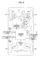
- Fig. 4 diagrammatically shows another embodiment of a four-wheel, front drive vehicle incorporating a steering control device according to the present invention, in which a steering angle is controlled for improving a steering characteristic.
- a hydraulic power steering apparatus 16' and a turning angle varying apparatus 70 connecting an upper steering shaft 54A and a lower steering shaft 54B are provided, instead of the electric power steering apparatus 16 and steering shaft 54 in Fig. 3.
- the upper steering shaft 54A is connected to the steering wheel 14, and the lower steering shaft 54 B is connected to a pinion shaft 74 via a joint 72.
- the electronic controller 48 signals of rotational angles ⁇ s and ⁇ a of the upper and lower steering shafts 54A and 54B, detected with steering angular sensors 80 and 82, respectively, instead of the signal of torque Ts detected with the torque sensor 56.
- the electronic controller 28 is fed with a command by the controller 48 and controls the turning angle varying apparatus 70, equipped with an electric motor 76 for adding the auxiliary steering angle component ⁇ ca, multiplied by the gain Kg, to the steering angle component ⁇ ab. Accordingly, the hydraulic power steering system 16' with the turning angle varying apparatus 70 and controller 28 construct an active steering apparatus.
- the controller 48 conducts a calculation of the steering angle ⁇ , as defined in the expression (2), according to a flowchart as shown in Fig. 5, using signals fed from various sensors including the signal of the upper steering shaft 54A, and, based upon the result of the calculation, the controller 28 adjusts the angular position of the lower steering shaft 54B to set the steering angle ⁇ on the steered wheels 10FL and 10FR.
- the signal ⁇ a may be used for monitoring an actual steering angle on the steered wheels and for returning it back to the neutral position after the modification of the steering characteristic according to the present invention.
- the other structure and components in Fig. 4 are similar to those in Fig. 3.
- Fig. 5 there is shown an exemplary flowchart executed in the steering control device (in the controller 48) in Figs. 3 or 4.
- the control according to the flowchart may be started by a closure of an ignition switch (not shown in Figs. 3 and 4) and cyclically repeated at a cycle time such as tens of milli-seconds during the operation of the vehicle.
- the steering angle ⁇ , ⁇ ab and ⁇ ca, yaw rate ⁇ , torque Ts, Ta, Tab and Tca and yaw moment Mb in the rightward direction are defined as positive.
- a road reaction force in the acceleration direction is defined as positive.
- step 10 the signals shown in Fig. 3 or 4 are read in.
- step 20 there is calculated the basic steering assist torque Tab (in Fig. 3) or steering angle component ⁇ ab (in Fig. 4).
- a map as shown in Fig. 6 may be used, in which a target basic steering assist torque is determined as a function of the steering torque Ts on the steering shaft 54 and vehicle velocity Vb.
- the steering angle component ⁇ ab may be determined by the angler position ⁇ s of the upper steering shaft 54A. Without any rotation of the steering wheel by the driver, the basic steering assist torque Tab and steering angle component ⁇ ab will be zero.
- steps 30 and 32 it is judged if either of TRC and ABS control is being operated.
- TRC When the vehicle is accelerated and an acceleration slip on at least either of the front (driven) wheels exceeds over a reference value, TRC will be operated to increase the braking force i.e. braking pressure on the corresponding wheel for preventing any acceleration slip from being excessive.
- ABS On the other hand, when the vehicle is decelerated and a deceleration or braking slip on at least either of the wheels exceeds over a reference value, ABS will be operated to decrease the braking pressure for on the corresponding wheel.
- Both TRC and ABS control is well known in the art, and a conventional manner of those control process may be employed in the present invention.
- the process will go to step 40 for calculating differences between longitudinal road reaction forces on the left and right wheels.
- step 40 for estimating the auxiliary steering assist torque Tca or auxiliary steering angle component ⁇ ca, first, the differences between the left and right longitudinal road reaction forces for the front wheels, ⁇ Fwf, and rear wheels, ⁇ Fwr, are calculated.
- the total longitudinal road reaction force (Fti) on a wheel is given by a sum of components in the acceleration direction, Fai, and deceleration direction, -Fbi.
- step 60 the auxiliary steering assist torque Tca or the auxiliary steering angle component ⁇ ca is calculated.
- auxiliary steering angle component ⁇ ca is determined as a function of the yaw moment Mb or the force difference ⁇ Fwf, the sign of which function is opposite to Mb or ⁇ Fwf.
- ⁇ ca any map (not shown) obtained experimentally and/or theoretically may be used in a manner realized by one of ordinary skill in the art.
- the gain Kg is determined as a function of an index of the vertical load shift between the left and right wheels or the degree of turning, using a map as shown in Fig. 7, in which, as the index, the absolute value of the yaw rate ⁇ of the vehicle body, detected with the yaw rate sensor 60.
- Kg is reduced as the magnitude of the yaw rate ⁇ increases.
- the automatic steering assist control irrespective of the driver's steering operation is fully effective only in a straight course for compensating for the yaw moment induced by the left and right wheels being operated on different frictional road surfaces, while suppressed on a road having a uniform frictional coefficient even when the differences between the road reaction forces on the left and right wheels is generated during turning of the vehicle.
- Kg to be used in the expressions (1) and (2) may be different from each other because of the difference of the amounts to be controlled. Further, different maps may be used during acceleration and deceleration of a vehicle. The map of Kg may be determined experimentally or theoretically in any manner which may be realized by one of ordinary skill in the art.
- step 80 the steering assist torque Ta or steering angle ⁇ is calculated according to the expression (1) or (2), and there is executed in step 100 the steering assist control for the electric power steering apparatus 16 in Fig. 3 or the active steering apparatus (the hydraulic power steering apparatus 16' and turning angle varying apparatus 70) in Fig. 4 through the controller 28 according to Ta or ⁇ resulting from steps 80 or 90.
- the longitudinal road reaction forces reacted on the wheels may be obtained by any ways other than the estimation from the braking pressures.
- torque detected on a wheel shaft with a torque sensor an output of driving and braking forces for a wheel from a motor in a wheel-in-motor vehicle, etc. may be used.
- Kg may be a function of parameters of any vehicle conditions and those controlled by the driver, such as a lateral acceleration, an angler position of the steering wheel, its time differential, the difference between the vertical loads on the left and right wheels and a combination thereof.
- the auxiliary steering assist torque against the yaw moment induced by the braking forces is directed in the same direction as the yaw moment required for turning the vehicle head along a curved course.
- the contribution of the auxiliary components Tca or ⁇ ca may be raised up during deceleration relative to during acceleration as shown by a broken line in Fig. 7.
- the steering control device according to the present invention may be employed in a rear drive vehicle and a four wheel drive vehicle.
Landscapes
- Engineering & Computer Science (AREA)
- Transportation (AREA)
- Mechanical Engineering (AREA)
- Chemical & Material Sciences (AREA)
- Combustion & Propulsion (AREA)
- Physics & Mathematics (AREA)
- Mathematical Physics (AREA)
- Steering Control In Accordance With Driving Conditions (AREA)
Applications Claiming Priority (2)
| Application Number | Priority Date | Filing Date | Title |
|---|---|---|---|
| JP2002342600 | 2002-11-26 | ||
| JP2002342600A JP4003627B2 (ja) | 2002-11-26 | 2002-11-26 | 車輌用操舵制御装置 |
Publications (3)
| Publication Number | Publication Date |
|---|---|
| EP1424263A2 true EP1424263A2 (de) | 2004-06-02 |
| EP1424263A3 EP1424263A3 (de) | 2004-12-01 |
| EP1424263B1 EP1424263B1 (de) | 2009-12-23 |
Family
ID=32290423
Family Applications (1)
| Application Number | Title | Priority Date | Filing Date |
|---|---|---|---|
| EP03026726A Expired - Lifetime EP1424263B1 (de) | 2002-11-26 | 2003-11-21 | Steuereinrichtung einer Fahrzeuglenkung |
Country Status (4)
| Country | Link |
|---|---|
| US (1) | US7073621B2 (de) |
| EP (1) | EP1424263B1 (de) |
| JP (1) | JP4003627B2 (de) |
| DE (1) | DE60330644D1 (de) |
Cited By (2)
| Publication number | Priority date | Publication date | Assignee | Title |
|---|---|---|---|---|
| WO2010020725A1 (fr) | 2008-08-19 | 2010-02-25 | Renault S.A.S. | Procede de detection d'une situation de freinage asymetrique pour un vehicule automobile, procede de controle de direction utilisant le procede de detection, et vehicule apte a mettre en oeuvre ces procedes |
| FR3076529A1 (fr) * | 2018-01-10 | 2019-07-12 | Jtekt Europe | Procede de compensation de deviation de trajectoire au freinage avec une direction assistee |
Families Citing this family (45)
| Publication number | Priority date | Publication date | Assignee | Title |
|---|---|---|---|---|
| JP4182014B2 (ja) * | 2004-03-02 | 2008-11-19 | 株式会社アドヴィックス | 車両の操舵制御装置 |
| US7295906B2 (en) * | 2004-03-05 | 2007-11-13 | Toyota Jidosha Kabushiki Kaisha | Vehicle stability control device |
| JP2005271822A (ja) * | 2004-03-25 | 2005-10-06 | Mitsubishi Fuso Truck & Bus Corp | 車両の自動減速制御装置 |
| JP4269994B2 (ja) * | 2004-03-25 | 2009-05-27 | 三菱ふそうトラック・バス株式会社 | 車両のステア特性制御装置 |
| JP4638185B2 (ja) * | 2004-08-04 | 2011-02-23 | 富士重工業株式会社 | 車両の挙動制御装置 |
| JP2006096230A (ja) * | 2004-09-30 | 2006-04-13 | Fuji Heavy Ind Ltd | 車両運動制御装置および車両運動制御方法 |
| JP4293106B2 (ja) * | 2004-10-14 | 2009-07-08 | トヨタ自動車株式会社 | 電動式パワーステアリング装置用制御装置 |
| JP4569280B2 (ja) * | 2004-12-03 | 2010-10-27 | トヨタ自動車株式会社 | 車輌用操舵制御装置 |
| JP4684658B2 (ja) * | 2005-01-11 | 2011-05-18 | 富士重工業株式会社 | 4輪駆動車のパワーステアリング装置 |
| JP2006197757A (ja) * | 2005-01-14 | 2006-07-27 | Nissan Motor Co Ltd | 車両の回生制動制御装置 |
| JP2006240572A (ja) * | 2005-03-07 | 2006-09-14 | Jtekt Corp | 車両姿勢制御システム |
| JP4600161B2 (ja) * | 2005-06-02 | 2010-12-15 | トヨタ自動車株式会社 | スプリット路面上での車輪の駆動滑りを抑制する車輌 |
| JP4853123B2 (ja) * | 2006-06-15 | 2012-01-11 | 株式会社アドヴィックス | 電動ステアリング制御装置 |
| JP4853122B2 (ja) * | 2006-06-15 | 2012-01-11 | 株式会社アドヴィックス | 電動ステアリング制御装置 |
| EP2017162B1 (de) * | 2007-07-19 | 2013-06-12 | Nissan Motor Co., Ltd. | Spurhaltesystem, Automobil und Spurhalteverfahren |
| CN101970274B (zh) * | 2008-03-13 | 2014-05-07 | 皇家飞利浦电子股份有限公司 | 用于车辆安全的传感器系统、车辆控制系统和司机信息系统 |
| JP4877384B2 (ja) * | 2009-12-01 | 2012-02-15 | トヨタ自動車株式会社 | 操舵装置 |
| JP5808977B2 (ja) * | 2011-08-19 | 2015-11-10 | Ntn株式会社 | 車両のヨーモーメント発生旋回効率化装置 |
| US9278709B2 (en) * | 2011-12-12 | 2016-03-08 | Steering Solutions Ip Holding Corporation | Steering system having compensation command calibration |
| US9387872B2 (en) * | 2012-06-18 | 2016-07-12 | Hanwha Techwin Co., Ltd. | Control method of vehicle, and vehicle adopting the method |
| US9676409B2 (en) | 2013-03-11 | 2017-06-13 | Steering Solutions Ip Holding Corporation | Road wheel disturbance rejection based on hand wheel acceleration |
| US10155531B2 (en) | 2013-04-30 | 2018-12-18 | Steering Solutions Ip Holding Corporation | Providing assist torque without hand wheel torque sensor |
| US9540044B2 (en) | 2013-11-15 | 2017-01-10 | Steering Solutions Ip Holding Corporation | Hand wheel angle from vehicle dynamic sensors or wheel speeds |
| US9540040B2 (en) | 2014-06-26 | 2017-01-10 | Steering Solutions Ip Holding Corporation | Phase plane based transitional damping for electric power steering |
| DE112015003513T5 (de) * | 2014-07-31 | 2017-07-06 | Trw Automotive U.S. Llc | Unterstützungskompensation für aktiv gesteuerte Servolenkungssysteme |
| US9409595B2 (en) * | 2014-09-15 | 2016-08-09 | Steering Solutions Ip Holding Corporation | Providing assist torque without hand wheel torque sensor for zero to low vehicle speeds |
| US10144445B2 (en) * | 2014-09-15 | 2018-12-04 | Steering Solutions Ip Holding Corporation | Modified static tire model for providing assist without a torque sensor for zero to low vehicle speeds |
| JP6179820B2 (ja) * | 2015-02-18 | 2017-08-16 | トヨタ自動車株式会社 | 車両の運転支援制御装置 |
| JP6496588B2 (ja) * | 2015-03-26 | 2019-04-03 | 株式会社Subaru | 車両挙動制御装置 |
| WO2016192806A1 (en) * | 2015-06-01 | 2016-12-08 | Volvo Truck Corporation | A driver assistance system |
| JP6055525B1 (ja) * | 2015-09-02 | 2016-12-27 | 富士重工業株式会社 | 車両の走行制御装置 |
| US10336363B2 (en) | 2015-09-03 | 2019-07-02 | Steering Solutions Ip Holding Corporation | Disabling controlled velocity return based on torque gradient and desired velocity error |
| US10464594B2 (en) | 2015-09-03 | 2019-11-05 | Steering Solutions Ip Holding Corporation | Model based driver torque estimation |
| US10399597B2 (en) * | 2015-10-09 | 2019-09-03 | Steering Solutions Ip Holding Corporation | Payload estimation using electric power steering signals |
| US10569801B2 (en) | 2015-10-09 | 2020-02-25 | Steering Solutions Ip Holding Corporation | Payload estimation using electric power steering signals |
| US10155534B2 (en) | 2016-06-14 | 2018-12-18 | Steering Solutions Ip Holding Corporation | Driver intent estimation without using torque sensor signal |
| KR101967465B1 (ko) * | 2016-12-08 | 2019-08-13 | 현대오트론 주식회사 | 가속도센서를 이용한 이종 노면에서의 감속제어장치 및 방법. |
| JP6743736B2 (ja) * | 2017-03-23 | 2020-08-19 | トヨタ自動車株式会社 | 車両のブレーキ装置 |
| JP6790971B2 (ja) * | 2017-04-03 | 2020-11-25 | トヨタ自動車株式会社 | 車両のブレーキ装置 |
| US10940851B2 (en) * | 2018-12-12 | 2021-03-09 | Waymo Llc | Determining wheel slippage on self driving vehicle |
| US11511790B2 (en) | 2019-02-14 | 2022-11-29 | Steering Solutions Ip Holding Corporation | Road friction coefficient estimation using steering system signals |
| US11498613B2 (en) | 2019-02-14 | 2022-11-15 | Steering Solutions Ip Holding Corporation | Road friction coefficient estimation using steering system signals |
| EP3736597A1 (de) * | 2019-05-06 | 2020-11-11 | Easymile | Verfahren und system zum modifizieren der geschwindigkeit eines fahrzeugs in abhängigkeit von der validierung seines berechneten lokalisierungsfeldes |
| JP2021011190A (ja) * | 2019-07-05 | 2021-02-04 | 株式会社Subaru | 車両の操舵支援装置 |
| US20220379889A1 (en) * | 2021-05-28 | 2022-12-01 | Zoox, Inc. | Vehicle deceleration planning |
Citations (4)
| Publication number | Priority date | Publication date | Assignee | Title |
|---|---|---|---|---|
| EP0296756A2 (de) | 1987-06-26 | 1988-12-28 | Ford Motor Company Limited | Steuersystem für ein Fahrzeug mit der Drehzahldifferenz der Räder als Eingangssignal |
| JP2861561B2 (ja) | 1991-12-26 | 1999-02-24 | 日産自動車株式会社 | 制動力制御装置 |
| JP2001080535A (ja) | 1999-09-13 | 2001-03-27 | Honda Motor Co Ltd | 車両の協調制御装置 |
| JP2001334947A (ja) | 2000-05-29 | 2001-12-04 | Koyo Seiko Co Ltd | 車両用操舵装置 |
Family Cites Families (9)
| Publication number | Priority date | Publication date | Assignee | Title |
|---|---|---|---|---|
| US5316379A (en) * | 1990-11-29 | 1994-05-31 | Robert Bosch Gmbh | Vehicle with an antilock controller |
| US6062336A (en) * | 1998-11-13 | 2000-05-16 | General Motors Corporation | Adaptive variable effort power steering system |
| DE10039782A1 (de) * | 2000-08-16 | 2002-02-28 | Daimler Chrysler Ag | Verfahren zur Regelung der Gier-und Querdynamik bei einem Straßenfahrzeug |
| DE10053604A1 (de) | 2000-10-28 | 2002-05-02 | Bosch Gmbh Robert | Einrichtung und Verfahren zum Betrieb eines Fahrzeugs |
| FR2817217B1 (fr) | 2000-11-24 | 2003-06-20 | Renault | Procede d'assistance d'un vehicule en freinage asymetrique |
| FR2821044B1 (fr) | 2001-02-21 | 2003-07-04 | Peugeot Citroen Automobiles Sa | Direction assistee electrique pour vehicule et procede de commande associe |
| GB0106925D0 (en) | 2001-03-20 | 2001-05-09 | Lucas Industries Ltd | Steering control during ABS split MU operation |
| EP1348610B1 (de) * | 2002-03-29 | 2008-01-30 | Jtekt Corporation | Fahrzeugsteuervorrichtung mit Servolenkung |
| US20060100766A1 (en) | 2002-07-05 | 2006-05-11 | Continental Teves Ag & Co. Ohg | Method for increasing the stability of a motor vehicle |
-
2002
- 2002-11-26 JP JP2002342600A patent/JP4003627B2/ja not_active Expired - Fee Related
-
2003
- 2003-11-13 US US10/706,096 patent/US7073621B2/en not_active Expired - Fee Related
- 2003-11-21 DE DE60330644T patent/DE60330644D1/de not_active Expired - Lifetime
- 2003-11-21 EP EP03026726A patent/EP1424263B1/de not_active Expired - Lifetime
Patent Citations (4)
| Publication number | Priority date | Publication date | Assignee | Title |
|---|---|---|---|---|
| EP0296756A2 (de) | 1987-06-26 | 1988-12-28 | Ford Motor Company Limited | Steuersystem für ein Fahrzeug mit der Drehzahldifferenz der Räder als Eingangssignal |
| JP2861561B2 (ja) | 1991-12-26 | 1999-02-24 | 日産自動車株式会社 | 制動力制御装置 |
| JP2001080535A (ja) | 1999-09-13 | 2001-03-27 | Honda Motor Co Ltd | 車両の協調制御装置 |
| JP2001334947A (ja) | 2000-05-29 | 2001-12-04 | Koyo Seiko Co Ltd | 車両用操舵装置 |
Cited By (5)
| Publication number | Priority date | Publication date | Assignee | Title |
|---|---|---|---|---|
| WO2010020725A1 (fr) | 2008-08-19 | 2010-02-25 | Renault S.A.S. | Procede de detection d'une situation de freinage asymetrique pour un vehicule automobile, procede de controle de direction utilisant le procede de detection, et vehicule apte a mettre en oeuvre ces procedes |
| FR2935122A1 (fr) * | 2008-08-19 | 2010-02-26 | Renault Sas | Procede de detection de freinage asymetrique pour un vehicule automobile. |
| FR3076529A1 (fr) * | 2018-01-10 | 2019-07-12 | Jtekt Europe | Procede de compensation de deviation de trajectoire au freinage avec une direction assistee |
| WO2019138178A1 (fr) * | 2018-01-10 | 2019-07-18 | Jtekt Europe | Procédé de compensation de déviation de trajectoire au freinage avec une direction assistée |
| US11383763B2 (en) | 2018-01-10 | 2022-07-12 | Jtekt Europe | Method for compensating for trajectory deviation when braking with power steering |
Also Published As
| Publication number | Publication date |
|---|---|
| EP1424263B1 (de) | 2009-12-23 |
| US7073621B2 (en) | 2006-07-11 |
| JP4003627B2 (ja) | 2007-11-07 |
| JP2004175192A (ja) | 2004-06-24 |
| US20040099469A1 (en) | 2004-05-27 |
| DE60330644D1 (de) | 2010-02-04 |
| EP1424263A3 (de) | 2004-12-01 |
Similar Documents
| Publication | Publication Date | Title |
|---|---|---|
| US7073621B2 (en) | Vehicle steering control device | |
| JP4930007B2 (ja) | 車両用操舵角制御装置 | |
| US8548706B2 (en) | Device operable to control turning of vehicle | |
| EP1595768B1 (de) | Einrichtung zur Fahrzeugzustandsregelung | |
| US7761215B2 (en) | Device operable to control turning of vehicle using driving and braking force for understeering and oversteering | |
| JP4029856B2 (ja) | 車輌の挙動制御装置 | |
| US7295906B2 (en) | Vehicle stability control device | |
| US6064930A (en) | Yaw moment control system in vehicle | |
| KR19980080864A (ko) | 차량의 자세 제어 장치 | |
| JPH08207607A (ja) | 4輪駆動車のトラクション制御装置 | |
| US20050205339A1 (en) | Steering control apparatus for a vehicle | |
| US8255122B2 (en) | Vehicle behavior control apparatus | |
| JP3827837B2 (ja) | 車両運動制御装置 | |
| JP4140611B2 (ja) | 車輌の挙動制御装置 | |
| JP4114065B2 (ja) | 四輪駆動車の挙動制御装置 | |
| JP2004231004A (ja) | 車輌用車輪状態推定装置 | |
| JP4284210B2 (ja) | 車両の操舵制御装置 | |
| JPH111129A (ja) | 4輪駆動車のスリップ制御装置 | |
| JP4572915B2 (ja) | 車輌用操舵制御装置 | |
| JP4685407B2 (ja) | 車輌の挙動制御装置 | |
| JP3678565B2 (ja) | 車両のステアリング装置 | |
| JPH01156139A (ja) | 車両用差動制限制御装置 | |
| JP2005138656A (ja) | 車輌の車体速度推定制御装置 |
Legal Events
| Date | Code | Title | Description |
|---|---|---|---|
| PUAI | Public reference made under article 153(3) epc to a published international application that has entered the european phase |
Free format text: ORIGINAL CODE: 0009012 |
|
| AK | Designated contracting states |
Kind code of ref document: A2 Designated state(s): AT BE BG CH CY CZ DE DK EE ES FI FR GB GR HU IE IT LI LU MC NL PT RO SE SI SK TR |
|
| AX | Request for extension of the european patent |
Extension state: AL LT LV MK |
|
| PUAL | Search report despatched |
Free format text: ORIGINAL CODE: 0009013 |
|
| AK | Designated contracting states |
Kind code of ref document: A3 Designated state(s): AT BE BG CH CY CZ DE DK EE ES FI FR GB GR HU IE IT LI LU MC NL PT RO SE SI SK TR |
|
| AX | Request for extension of the european patent |
Extension state: AL LT LV MK |
|
| RIC1 | Information provided on ipc code assigned before grant |
Ipc: 7B 62D 153:00 Z Ipc: 7B 60T 8/00 B Ipc: 7B 62D 105:00 Z Ipc: 7B 62D 6/00 A Ipc: 7B 62D 137:00 Z Ipc: 7B 62D 113:00 Z Ipc: 7B 62D 101:00 Z Ipc: 7B 62D 119:00 Z Ipc: 7B 62D 131:00 Z Ipc: 7B 62D 111:00 Z |
|
| 17P | Request for examination filed |
Effective date: 20041116 |
|
| 17Q | First examination report despatched |
Effective date: 20050318 |
|
| AKX | Designation fees paid |
Designated state(s): DE FR GB |
|
| GRAP | Despatch of communication of intention to grant a patent |
Free format text: ORIGINAL CODE: EPIDOSNIGR1 |
|
| RIC1 | Information provided on ipc code assigned before grant |
Ipc: B62D 6/00 20060101AFI20060925BHEP Ipc: B60T 8/00 20060101ALI20060925BHEP |
|
| GRAS | Grant fee paid |
Free format text: ORIGINAL CODE: EPIDOSNIGR3 |
|
| RIN1 | Information on inventor provided before grant (corrected) |
Inventor name: TSUCHIYA, YOSHIAKIC/O TOYOTA JIDOSHA K.K. Inventor name: HIROSE, TAROC/O TOYOTA JIDOSHA K.K. Inventor name: KOIBUCHI, KENC/O TOYOTA JIDOSHA K.K. |
|
| GRAA | (expected) grant |
Free format text: ORIGINAL CODE: 0009210 |
|
| AK | Designated contracting states |
Kind code of ref document: B1 Designated state(s): DE FR GB |
|
| REG | Reference to a national code |
Ref country code: GB Ref legal event code: FG4D |
|
| REF | Corresponds to: |
Ref document number: 60330644 Country of ref document: DE Date of ref document: 20100204 Kind code of ref document: P |
|
| PLBE | No opposition filed within time limit |
Free format text: ORIGINAL CODE: 0009261 |
|
| STAA | Information on the status of an ep patent application or granted ep patent |
Free format text: STATUS: NO OPPOSITION FILED WITHIN TIME LIMIT |
|
| 26N | No opposition filed |
Effective date: 20100924 |
|
| REG | Reference to a national code |
Ref country code: GB Ref legal event code: 746 Effective date: 20130827 |
|
| REG | Reference to a national code |
Ref country code: DE Ref legal event code: R084 Ref document number: 60330644 Country of ref document: DE Effective date: 20130829 |
|
| PGFP | Annual fee paid to national office [announced via postgrant information from national office to epo] |
Ref country code: DE Payment date: 20141118 Year of fee payment: 12 Ref country code: FR Payment date: 20141110 Year of fee payment: 12 Ref country code: GB Payment date: 20141119 Year of fee payment: 12 |
|
| REG | Reference to a national code |
Ref country code: DE Ref legal event code: R119 Ref document number: 60330644 Country of ref document: DE |
|
| GBPC | Gb: european patent ceased through non-payment of renewal fee |
Effective date: 20151121 |
|
| REG | Reference to a national code |
Ref country code: FR Ref legal event code: ST Effective date: 20160729 |
|
| PG25 | Lapsed in a contracting state [announced via postgrant information from national office to epo] |
Ref country code: GB Free format text: LAPSE BECAUSE OF NON-PAYMENT OF DUE FEES Effective date: 20151121 Ref country code: DE Free format text: LAPSE BECAUSE OF NON-PAYMENT OF DUE FEES Effective date: 20160601 |
|
| PG25 | Lapsed in a contracting state [announced via postgrant information from national office to epo] |
Ref country code: FR Free format text: LAPSE BECAUSE OF NON-PAYMENT OF DUE FEES Effective date: 20151130 |