EP1415868A2 - Dispositif de coussin gonflable - Google Patents
Dispositif de coussin gonflable Download PDFInfo
- Publication number
- EP1415868A2 EP1415868A2 EP03022662A EP03022662A EP1415868A2 EP 1415868 A2 EP1415868 A2 EP 1415868A2 EP 03022662 A EP03022662 A EP 03022662A EP 03022662 A EP03022662 A EP 03022662A EP 1415868 A2 EP1415868 A2 EP 1415868A2
- Authority
- EP
- European Patent Office
- Prior art keywords
- outer bag
- bag
- gas
- inner bag
- airbag
- Prior art date
- Legal status (The legal status is an assumption and is not a legal conclusion. Google has not performed a legal analysis and makes no representation as to the accuracy of the status listed.)
- Withdrawn
Links
Images


Classifications
-
- B—PERFORMING OPERATIONS; TRANSPORTING
- B60—VEHICLES IN GENERAL
- B60R—VEHICLES, VEHICLE FITTINGS, OR VEHICLE PARTS, NOT OTHERWISE PROVIDED FOR
- B60R21/00—Arrangements or fittings on vehicles for protecting or preventing injuries to occupants or pedestrians in case of accidents or other traffic risks
- B60R21/02—Occupant safety arrangements or fittings, e.g. crash pads
- B60R21/16—Inflatable occupant restraints or confinements designed to inflate upon impact or impending impact, e.g. air bags
- B60R21/23—Inflatable members
- B60R21/231—Inflatable members characterised by their shape, construction or spatial configuration
- B60R21/233—Inflatable members characterised by their shape, construction or spatial configuration comprising a plurality of individual compartments; comprising two or more bag-like members, one within the other
-
- B—PERFORMING OPERATIONS; TRANSPORTING
- B60—VEHICLES IN GENERAL
- B60R—VEHICLES, VEHICLE FITTINGS, OR VEHICLE PARTS, NOT OTHERWISE PROVIDED FOR
- B60R21/00—Arrangements or fittings on vehicles for protecting or preventing injuries to occupants or pedestrians in case of accidents or other traffic risks
- B60R21/02—Occupant safety arrangements or fittings, e.g. crash pads
- B60R21/16—Inflatable occupant restraints or confinements designed to inflate upon impact or impending impact, e.g. air bags
- B60R21/23—Inflatable members
- B60R21/231—Inflatable members characterised by their shape, construction or spatial configuration
- B60R21/2334—Expansion control features
- B60R21/2346—Soft diffusers
-
- B—PERFORMING OPERATIONS; TRANSPORTING
- B60—VEHICLES IN GENERAL
- B60R—VEHICLES, VEHICLE FITTINGS, OR VEHICLE PARTS, NOT OTHERWISE PROVIDED FOR
- B60R21/00—Arrangements or fittings on vehicles for protecting or preventing injuries to occupants or pedestrians in case of accidents or other traffic risks
- B60R21/02—Occupant safety arrangements or fittings, e.g. crash pads
- B60R21/16—Inflatable occupant restraints or confinements designed to inflate upon impact or impending impact, e.g. air bags
- B60R21/26—Inflatable occupant restraints or confinements designed to inflate upon impact or impending impact, e.g. air bags characterised by the inflation fluid source or means to control inflation fluid flow
- B60R21/276—Inflatable occupant restraints or confinements designed to inflate upon impact or impending impact, e.g. air bags characterised by the inflation fluid source or means to control inflation fluid flow with means to vent the inflation fluid source, e.g. in case of overpressure
-
- B—PERFORMING OPERATIONS; TRANSPORTING
- B60—VEHICLES IN GENERAL
- B60R—VEHICLES, VEHICLE FITTINGS, OR VEHICLE PARTS, NOT OTHERWISE PROVIDED FOR
- B60R21/00—Arrangements or fittings on vehicles for protecting or preventing injuries to occupants or pedestrians in case of accidents or other traffic risks
- B60R21/02—Occupant safety arrangements or fittings, e.g. crash pads
- B60R21/16—Inflatable occupant restraints or confinements designed to inflate upon impact or impending impact, e.g. air bags
- B60R21/20—Arrangements for storing inflatable members in their non-use or deflated condition; Arrangement or mounting of air bag modules or components
- B60R21/217—Inflation fluid source retainers, e.g. reaction canisters; Connection of bags, covers, diffusers or inflation fluid sources therewith or together
Definitions
- the present invention relates to an airbag apparatus provided to a high-speed mobile unit such as a car for protecting an occupant in a car crash or the like, and more particularly, it concerns an airbag apparatus having the function of preventing the outflow of gas from a vent hole until the gas pressure in the airbag reaches a predetermined level or more.
- Airbag apparatuses have a retainer to which an airbag is connected, an inflator for generating gas for inflating the airbag, and a cover and so on for covering the airbag.
- the inflator generates gas to inflate the airbag in a car crash.
- the airbag opens the cover to inflate into the interior of a vehicle.
- the airbag apparatuses have a vent hole. When an occupant has hit against an inflated airbag, gas in the airbag flows out through the vent hole to absorb impact applied to the occupant.
- an airbag apparatus as defined in claim 1.
- the dependent claim defines a preferred embodiment of the airbag apparatus.
- An airbag apparatus has an airbag including an inner bag and an outer bag, wherein gas from a gas generating means is supplied into the inner bag to inflate the inner bag; the gas is discharged through an opening of the inner bag into the outer bag to inflate the outer bag; and the gas in the outer bag is discharged through a vent hole.
- the vent hole is provided to a retainer to which at least one of the inner bag and the outer bag is connected; and the vent hole has a closing means for closing the vent hole until the inner pressure of the outer bag reaches a predetermined level.
- the gas generating means when the gas generating means is activated, gas is let in the inner bag to inflate the inner bag.
- the gas in the inner bag then flows into the outer bag to inflate the outer bag.
- the vent-hole closing means of the retainer opens and so the gas is discharged through the vent hole.
- the closing means does not open until the gas flows out from the inner bag into the outer bag and thus the gas pressure in the outer bag reaches a predetermined level.
- the closing means opens and so the gas flows out through the vent hole.
- the wide-inflated airbag can receive the occupant securely.
- the outer bag holds a sufficient amount of gas therein and so when the occupant has hit against the outer bag at a high speed, the gas flows out from the outer bag to absorb the impact.
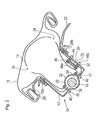
- Fig. 1 is a sectional view of a passenger-side airbag apparatus according to an embodiment of the present invention
- Fig. 2 is a sectional view of the airbag apparatus immediately after a module cover has started to open
- Fig. 3 is a sectional view of the airbag apparatus when an outer bag has fully inflated
- Fig. 4 is a sectional view of the airbag apparatus after an occupant has hit against the airbag
- Fig. 5 is an exploded perspective view of a vent-hole closing means
- Fig. 6(a) is a sectional view of an essential part of the vent-hole closing means, showing the structure thereof
- Fig. 6(b) is a sectional view of an essential part of the vent-hole closing means when it opens
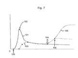
- Fig. 7 is an operational characteristic diagram of the airbag apparatus.
- An airbag apparatus 10 is a passenger-side airbag apparatus mounted on the top of an instrument panel (not shown) in front of a front passenger seat of a car.
- Numeral 8 in Fig. 4 denotes a windshield of a car.
- the airbag apparatus 10 includes a container-like retainer 12 of which the front side is open, an airbag (formed of an inner bag 14 and an outer bag 16) arranged in the retainer 12 in a folded condition, a substantially column-like inflator 18 serving as a gas generating means for inflating the airbag, a module cover 20 for covering the front opening of the retainer 12, a vent holes 22 provided to the retainer 12, and a lid 24 serving as a closing means for closing the vent hole 22.
- the module cover 20 is mounted to the retainer 12 with a mounting member 20b.
- a tear line 20a is provided on the back of the module cover 20.
- the retainer 12 is open on the top thereof in Fig. 1 and has a recess 12a on the bottom, which expands outward in a semicircular shape.
- the lower half of the inflator 18 is arranged in the recess 12a and fixed on the bottom of the retainer 12 with a holding member 30 covering from above.
- the entire holding member 30 is also semicircular along the outer periphery of the inflator 18.
- the holding member 30 has an opening 32 for passing gas through.
- the inner bag 14 has a capacity from about 1.5 times as high as that of the retainer 12 to about half of that of the outer bag 16.
- the outer bag 16 has a capacity equal to that of a general passenger-side airbag.
- the inner bag 14 is arranged in the outer bag 16.
- the end of the inner bag 14 has one or more gas-through openings 34 for communicating the inside of the inner bag 14 with the inside of the outer bag 16.
- the inner bag 14 and the outer bag 16 have openings 36 and 38, respectively, on the lower left of Fig. 1.
- the rims of the openings 36 and 38 are sandwiched and fixed between the holding member 30 and the bottom of the retainer 12.
- the holding member 30 and the openings 36 and 38 are each fixed to the retainer 12 with a bolt 40 and a nut 42.
- the vent hole 22 is provided at the lower part of the side of the inner bag 14.
- the outer bag 16 has an opening 44 in the position overlapping with the vent hole 22.
- the lid 24 is placed on the opening 44 from the inside of the outer bag 16, the rims of the lid 24 and the opening 44 being fixed to the rim of the vent hole 22 of the retainer 12 with a holding member 46.
- the lid 24 includes a substantially disk-shaped body 24b and a plurality of projections 24a project radially from the periphery thereof.
- a thick plate 24c is placed on the center of the body 24b. The diameter of the disk-shaped body 24b is smaller than that of the vent hole 22.
- a packing 50 is interposed between the outer bag 16 (not shown in Fig. 5) and the inner surface of the retainer 12.
- the holding member 46 is shaped like a rectangular plate having a through hole 46a in the center.
- the thick plate 24c of the lid 24 is fitted in the through hole 46a.
- Stud bolts 46b project from the four corners of the holding member 46.
- the packing 50, the retainer 12, and the rim of the opening 44 of the outer bag 16 have small holes 50h and 12h (small holds of the outer bag 16 are not shown) for passing the stud bolts 46b through, respectively.
- the stud bolts 46b are inserted in the small holes with the lid 24 interposed between the holding member 46 and the outer bag 16, and nuts 52 are tightened to the stud bolts 46b, thereby retaining the lid 24 to the retainer 12.
- the projections 24a of the lid 24 are sandwiched between the holding member 46 and the retainer 12.
- the inner bag 14 is placed in a relatively inner part of the retainer 12 in a folded condition. How the inner bag 14 and the outer bag 16 are folded is not limited to that in the drawing.
- the inflator 18 When the inflator 18 is activated to emit gas in a car crash, the gas from the inflator 18 is let in the inner bag 14 through the gas-through opening 32 of the holding member 30 to inflate the inner bag 14 first.
- the module cover 20 since the inner capacity of the inner bag 14 is higher than that of the retainer 12, upon the inflation of the inner bag 14, the module cover 20 is torn open along the tear line 20a by the inflation pressure of the inner bag 14. The inner bag 14 pushes open the module cover 20 to inflate into the interior of the vehicle.
- the amount of gas that flows out from the inner bag 14 into the outer bag 16 through the gas-through openings 34 at the end of the inner bag 14 is very little until the inner bag 14 starts to inflate into the interior of the vehicle, so that the outer bag 16 is pushed out from the retainer 12 by the inner bag 14 in little inflated condition.
- Fig. 7 is a graph showing the operational characteristics of the airbag apparatus 10.
- the gas from the inflator 18 is first let in the inner bag 14 to increase the inner pressure (curve 101) of the inner bag 14, thereby tearing open the module cover 20 (point 102), as shown in Fig. 7.
- the gas in the inner bag 14 flows into the outer bag 16 through the gas-through openings 34.
- the outer bag 16 inflates sufficiently wide.
- the inner pressure (curve 103) of the outer bag 16 does not exceed the predetermined level, so that the lid 24 does not open. Accordingly, the outer bag 16 inflates sufficiently wide to thereby receive the occupant securely.
- the lid 24 opens (point 106) to open the vent hole 22. Therefore, the gas in the outer bag 16 flows out to absorb the impact sufficiently.
- Fig. 7 shows the change in the inner pressure of the outer bag 16 after the occupant has entered the outer bag 16 in the case where the retainer 12 has not the vent hole 22, by a chain double-dashed line (curve 105).
- the adjustment of the cross-sectional area (the width and the thickness) and the number of the projections 24a of the lid 24 allows the control of the inner pressure of the outer bag 16 during the opening of the vent hole 22.
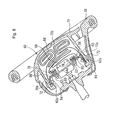
- Fig. 8 is a sectional view of a driver-seat airbag apparatus according to an embodiment of the present invention
- Fig. 9 is an exploded perspective view of a retainer and a breakable sheet of the airbag apparatus
- Fig. 10 is an enlarged sectional view of the vicinity of a vent hole of the airbag apparatus
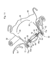
- Fig. 11 is a sectional view of the airbag apparatus immediately after a module cover has started to open
- Fig. 12 is a sectional view of the airbag apparatus after an outer bag has fully inflated
- Fig. 13 is a sectional view of the airbag apparatus after an occupant has hit against it.
- An airbag apparatus 60 is a driver-seat airbag apparatus arranged inside a steering wheel 58.
- the airbag apparatus 60 includes a retainer 62, an inflator 64 mounted to the retainer 62, an inner bag 66, an outer bag 68, and a module cover 70 for covering the folded airbag (the inner bag 66 and the outer bag 68).
- the retainer 62 includes a main surface 62a (see Fig. 9) to which the inner bag 66 is mounted and upstanding pieces 62b standing backward (opposite to the occupant) from the rim of the main surface 62a.
- the module cover 70 has legs 70a on the side, which are fastened to the upstanding pieces 62b of the retainer 62 with rivets 72. With the embodiment, the rim of the outer bag 68 is sandwiched between the legs 70a and the upstanding pieces 62b. The rivets 72 also pass through the rim of the outer bag 68.
- the inflator 64 is secured to the retainer 62 such that the upper end thereof comes in the inner bag 66 through an inflator-mounting opening 76 in the main surface 62a.
- Reference numeral 78 denotes an airbag mounting member called a ferrule.
- the opening rim of the inner bag 66 is sandwiched between the ferrule 78 and the opening 76 of the main surface 62a, and thus the inner bag 66 is secured to the retainer 62.
- Bolts 80 are fixed to the ferrule 78. The bolts 80 are inserted in bolt insertion holes of the opening rim of the inner bag 66, the main surface 62a of the retainer 62 and a flange 64a of the inflator 64 and nuts 82 are tightened to the bolts 80.
- the module cover 70 has a tear line 70b for tearing open the module cover 70 on the back.
- the main surface 62a of the retainer 62 has a plurality of vent holes 84 along the outer periphery thereof.
- a breakable sheet (hereinafter, simply referred to as a sheet) 86 is superposed on the main surface 62a to close the vent holes 84.
- the sheet 86 is made of flexible resin, woven fabric, and the like but is not limited to that.
- the sheet 86 is bonded to the main surface 62a with a bonding or adhesive agent; however, the way of fixing the sheet 86 is not limited to that.
- the inner bag 66 is arranged inside the outer bag 68, as shown in the drawing.
- the capacity of the inner bag 66 is from about 1.5 times as high as that of the space surrounded by the module cover 70 and the main surface 62a of the retainer 62 to about half of that of the outer bag 68.
- the outer bag 68 has a capacity substantially equal to that of a general driver-seat airbag.
- the end of the inner bag 66 has gas-through openings 90 for communicating the inside of the inner bag 66 with the inside of the outer bag 68.
- the inflator 64 When the inflator 64 is activated to emit gas in a car crash, the gas from the inflator 64 is let in the inner bag 66 to inflate the inner bag 66 first.
- the module cover 20 is torn open along the tear line 70b by the inflation pressure of the inner bag 66 when the inner bag 66 has inflated.
- the inner bag 66 pushes open the module cover 70 to inflate into the interior of the vehicle.
- the amount of gas that flows out from the inner bag 66 into the outer bag 68 through the gas-through openings 90 at the end of the inner bag 66 is very little until the inner bag 66 starts to inflate into the interior of the vehicle, so that the outer bag 68 is pushed out in little inflated condition by the inner bag 66 into the interior of the vehicle.
- the gas in the inner bag 66 is discharged into the outer bag 68 through the gas-through openings 90, and the outer bag 68 inflates sufficiently wide, as shown in Fig. 12.
- the airbag apparatus 60 even when the inner pressure of the inner bag 66 has become high before the module cover 70 is pushed open, the gas does not flows out through the vent holes 84, which allows the airbag to inflate early and the low-capacity inflator to be provided.
- the vent holes 84 are opened without failure.
- the airbag apparatus according to the invention can be applied not only to occupant protection airbags but also to pedestrian protection airbag apparatuses and so on that deploy outward of the vehicle.
- the invention provides an airbag apparatus capable of keeping the vent hole closed until the inner pressure of the outer bag has increased to a predetermined level by the crash of the occupant, thereby inflating an airbag early or providing a low-capacity gas generating means.
- the vent hole is opened without failure to absorb the impact of the occupant.
Landscapes
- Engineering & Computer Science (AREA)
- Mechanical Engineering (AREA)
- Physics & Mathematics (AREA)
- Fluid Mechanics (AREA)
- Air Bags (AREA)
Applications Claiming Priority (2)
| Application Number | Priority Date | Filing Date | Title |
|---|---|---|---|
| JP2002312955 | 2002-10-28 | ||
| JP2002312955A JP4100129B2 (ja) | 2002-10-28 | 2002-10-28 | エアバッグ装置 |
Publications (2)
| Publication Number | Publication Date |
|---|---|
| EP1415868A2 true EP1415868A2 (fr) | 2004-05-06 |
| EP1415868A3 EP1415868A3 (fr) | 2005-09-14 |
Family
ID=32089473
Family Applications (1)
| Application Number | Title | Priority Date | Filing Date |
|---|---|---|---|
| EP03022662A Withdrawn EP1415868A3 (fr) | 2002-10-28 | 2003-10-07 | Dispositif de coussin gonflable |
Country Status (3)
| Country | Link |
|---|---|
| US (1) | US7040655B2 (fr) |
| EP (1) | EP1415868A3 (fr) |
| JP (1) | JP4100129B2 (fr) |
Cited By (5)
| Publication number | Priority date | Publication date | Assignee | Title |
|---|---|---|---|---|
| DE102004053674B4 (de) * | 2004-11-03 | 2008-09-25 | Autoliv Development Ab | Frontgassack-Modul für ein Kraftfahrzeug |
| EP2110287A1 (fr) * | 2008-04-17 | 2009-10-21 | Dalphi Metal Espana, S.A. | Dispositif de ventilation |
| CN103448661A (zh) * | 2013-08-23 | 2013-12-18 | 浙江吉利汽车研究院有限公司 | 安全气囊及具有该安全气囊的汽车 |
| GB2508040A (en) * | 2012-11-16 | 2014-05-21 | Ford Global Tech Llc | Bag in bag safety restraint with directional inflation |
| CN106541923A (zh) * | 2015-09-22 | 2017-03-29 | 上海汽车集团股份有限公司 | 汽车及其安全气囊系统 |
Families Citing this family (24)
| Publication number | Priority date | Publication date | Assignee | Title |
|---|---|---|---|---|
| JP4290501B2 (ja) * | 2003-08-07 | 2009-07-08 | タカタ株式会社 | エアバッグ装置、エアバッグ装置付オートバイ |
| DE202004018121U1 (de) * | 2004-11-22 | 2005-04-07 | Trw Automotive Safety Sys Gmbh | Fahrzeuglenkrad mit Gassackmodul und Abströmöffnung |
| JP4534762B2 (ja) * | 2004-12-28 | 2010-09-01 | タカタ株式会社 | 運転席用エアバッグ装置 |
| JP4687105B2 (ja) * | 2004-12-28 | 2011-05-25 | タカタ株式会社 | エアバッグ装置 |
| DE102005009764B4 (de) * | 2005-03-03 | 2019-05-09 | Volkswagen Ag | Sicherheitseinrichtung für ein Fahrzeug, insbesondere für ein Kraftfahrzeug |
| DE202005005466U1 (de) * | 2005-04-07 | 2005-07-14 | Trw Automotive Safety Systems Gmbh | Fahrzeuginsassen-Rückhaltevorrichtung |
| DE102005020053A1 (de) * | 2005-04-29 | 2006-11-16 | Trw Automotive Gmbh | Gassackmodul |
| US20070085316A1 (en) * | 2005-10-14 | 2007-04-19 | Tk Holdings, Inc. | Airbag folding method and folded airbag produced thereby |
| JP2007118816A (ja) * | 2005-10-28 | 2007-05-17 | Takata Corp | 乗員拘束装置 |
| KR100747909B1 (ko) * | 2006-07-10 | 2007-08-08 | 현대자동차주식회사 | 조수석 에어백 하우징 구조 |
| KR100778589B1 (ko) * | 2006-11-07 | 2007-11-22 | 현대자동차주식회사 | 차량용 운전석 에어백 |
| JP2008213519A (ja) * | 2007-02-28 | 2008-09-18 | Toyota Motor Corp | エアバッグ装置 |
| JP5641637B2 (ja) * | 2009-12-23 | 2014-12-17 | タカタ株式会社 | エアバッグ及びエアバッグ装置 |
| JP5943464B2 (ja) | 2011-05-06 | 2016-07-05 | 日本プラスト株式会社 | エアバッグ及びその折り畳み方法 |
| JP5883613B2 (ja) | 2011-10-20 | 2016-03-15 | 芦森工業株式会社 | エアバッグ装置 |
| DE112015000442T5 (de) | 2014-01-21 | 2016-12-01 | Tk Holdings Inc. | Insassenseitenairbag |
| JP6584068B2 (ja) | 2014-12-12 | 2019-10-02 | Joyson Safety Systems Japan株式会社 | エアバッグ及びエアバッグ装置 |
| JP6680233B2 (ja) * | 2017-02-02 | 2020-04-15 | 豊田合成株式会社 | エアバッグ |
| CN111094078B (zh) * | 2017-10-05 | 2024-02-13 | 奥托立夫开发公司 | 安全气囊装置 |
| JP7053301B2 (ja) * | 2018-02-16 | 2022-04-12 | 日本プラスト株式会社 | エアバッグ装置 |
| JP7001018B2 (ja) * | 2018-08-10 | 2022-01-19 | 豊田合成株式会社 | エアバッグ |
| WO2020217824A1 (fr) * | 2019-04-25 | 2020-10-29 | オートリブ ディベロップメント エービー | Dispositif de coussin de sécurité gonflable pour conducteur |
| US11180103B2 (en) | 2019-10-28 | 2021-11-23 | Autoliv Asp, Inc. | Frontal airbag systems |
| JP7400764B2 (ja) * | 2021-03-29 | 2023-12-19 | 豊田合成株式会社 | エアバッグ装置 |
Citations (5)
| Publication number | Priority date | Publication date | Assignee | Title |
|---|---|---|---|---|
| JPH1076907A (ja) | 1996-09-06 | 1998-03-24 | Bridgestone Corp | エアバッグ装置 |
| US5743558A (en) | 1997-02-11 | 1998-04-28 | Takata, Inc. | Air cushion module with rotating vent ring |
| US5927748A (en) | 1997-06-26 | 1999-07-27 | O'driscoll; Peter | Multi-stage inflatable bag for vehicular safety systems |
| US6158770A (en) | 1997-01-17 | 2000-12-12 | General Motors Corporation | Air bag module with variable inflation |
| GB2371779A (en) | 2001-02-06 | 2002-08-07 | Autoliv Dev | An air bag module with delayed venting means |
Family Cites Families (36)
| Publication number | Priority date | Publication date | Assignee | Title |
|---|---|---|---|---|
| JPH02115747A (ja) | 1988-10-25 | 1990-04-27 | Nec Corp | ガスの貯蔵容器 |
| US5234229A (en) | 1992-02-25 | 1993-08-10 | General Motors Corporation | Pressure limited restraint system |
| DE4228617C1 (de) | 1992-08-28 | 1993-10-21 | Daimler Benz Ag | Luftansaugendes Gassack-Aufprallschutzsystem für einen Kraftwageninsassen |
| US5257818A (en) | 1992-09-08 | 1993-11-02 | Trw Vehicle Safety Systems Inc. | Apparatus for rapidly changing the temperature of a device in an inflatable restraint system |
| JPH06127329A (ja) | 1992-10-13 | 1994-05-10 | Toyota Motor Corp | 車両用エアバッグ装置 |
| JPH06305391A (ja) | 1993-04-21 | 1994-11-01 | Takata Kk | エアバッグ |
| US5478111A (en) | 1993-08-11 | 1995-12-26 | Morton International, Inc. | Dynamic burn vents for the cushion of an air bag module |
| JPH07329697A (ja) | 1994-06-13 | 1995-12-19 | Takata Kk | エアバッグ |
| US5645297A (en) | 1995-08-22 | 1997-07-08 | Morton International, Inc. | Regulation of pressure in an automotive airbag module |
| US5603526A (en) * | 1996-01-16 | 1997-02-18 | Morton International, Inc. | Pressure vent for air bag cushion |
| US5669628A (en) | 1996-04-08 | 1997-09-23 | Morton International, Inc. | Air bag cushion protection during both normal and out of position deployments |
| US5683102A (en) | 1996-04-08 | 1997-11-04 | Morton International, Inc. | Ported passenger airbag module can |
| JPH09323604A (ja) | 1996-06-07 | 1997-12-16 | Honda Motor Co Ltd | 乗員拘束装置用エアバッグ |
| US5704639A (en) * | 1996-07-09 | 1998-01-06 | Breed Automotive Technology, Inc. | Pressure sensitive airbag vent mechanism |
| JPH1035405A (ja) | 1996-07-18 | 1998-02-10 | Fuji Heavy Ind Ltd | 車両用エアバッグ装置のガス圧調整装置 |
| JPH1067289A (ja) | 1996-08-29 | 1998-03-10 | Aisin Seiki Co Ltd | 車両用エアバッグ装置 |
| JPH1076896A (ja) | 1996-09-03 | 1998-03-24 | Aisin Seiki Co Ltd | 車両用エアバッグ装置 |
| GB2334492B (en) * | 1997-11-28 | 2002-05-15 | Nihon Plast Co Ltd | Air bag, air bag apparatus, and steering wheel |
| JPH11268605A (ja) | 1998-03-25 | 1999-10-05 | Mazda Motor Corp | 自動車のエアバッグ装置 |
| JP3646005B2 (ja) | 1998-05-26 | 2005-05-11 | 本田技研工業株式会社 | エアバッグ装置 |
| JP3566079B2 (ja) | 1998-05-26 | 2004-09-15 | 本田技研工業株式会社 | エアバッグ装置 |
| JP3660129B2 (ja) | 1998-05-26 | 2005-06-15 | 本田技研工業株式会社 | エアバッグ装置 |
| JP3566081B2 (ja) | 1998-05-26 | 2004-09-15 | 本田技研工業株式会社 | エアバッグ装置 |
| JP3566082B2 (ja) | 1998-05-26 | 2004-09-15 | 本田技研工業株式会社 | エアバッグ装置 |
| JP3566080B2 (ja) | 1998-05-26 | 2004-09-15 | 本田技研工業株式会社 | エアバッグ装置 |
| JP3788033B2 (ja) | 1998-05-29 | 2006-06-21 | タカタ株式会社 | エアバッグ装置 |
| US6086092A (en) * | 1998-07-07 | 2000-07-11 | Trw Vehicle Safety Systems Inc. | Inflatable vehicle occupant protection device |
| DE19933836A1 (de) * | 1998-07-21 | 2000-02-10 | Irene Amon | Airbag mit Außenhülle |
| JP3694727B2 (ja) * | 1998-07-27 | 2005-09-14 | 日産自動車株式会社 | 自動車用安全装置 |
| DE19847854C2 (de) * | 1998-10-16 | 2002-06-20 | Breed Automotive Tech | Zweikammerluftsack |
| DE29820479U1 (de) * | 1998-11-09 | 2000-03-30 | Glathe Jens | Airbag-Sicherheitssystem mit Prallpolster und 2 oder mehreren Airbags und gesteuerten Auslaßventilen |
| JP4075194B2 (ja) | 1999-03-05 | 2008-04-16 | 三菱自動車工業株式会社 | エアバッグ装置 |
| US6199895B1 (en) | 1999-03-25 | 2001-03-13 | Brian T. Seymour | Inflatable restraint system with selectable ventilation |
| JP3239118B2 (ja) * | 1999-09-30 | 2001-12-17 | 日本プラスト株式会社 | エアバッグ及びエアバッグ装置 |
| JP4759867B2 (ja) * | 2001-07-25 | 2011-08-31 | タカタ株式会社 | エアバッグ装置 |
| US6959945B2 (en) * | 2002-09-16 | 2005-11-01 | Trw Vehicle Safety Systems Inc. | Air bag module with vent controlled by tether |
-
2002
- 2002-10-28 JP JP2002312955A patent/JP4100129B2/ja not_active Expired - Fee Related
-
2003
- 2003-10-07 EP EP03022662A patent/EP1415868A3/fr not_active Withdrawn
- 2003-10-07 US US10/679,868 patent/US7040655B2/en not_active Expired - Fee Related
Patent Citations (5)
| Publication number | Priority date | Publication date | Assignee | Title |
|---|---|---|---|---|
| JPH1076907A (ja) | 1996-09-06 | 1998-03-24 | Bridgestone Corp | エアバッグ装置 |
| US6158770A (en) | 1997-01-17 | 2000-12-12 | General Motors Corporation | Air bag module with variable inflation |
| US5743558A (en) | 1997-02-11 | 1998-04-28 | Takata, Inc. | Air cushion module with rotating vent ring |
| US5927748A (en) | 1997-06-26 | 1999-07-27 | O'driscoll; Peter | Multi-stage inflatable bag for vehicular safety systems |
| GB2371779A (en) | 2001-02-06 | 2002-08-07 | Autoliv Dev | An air bag module with delayed venting means |
Cited By (10)
| Publication number | Priority date | Publication date | Assignee | Title |
|---|---|---|---|---|
| DE102004053674B4 (de) * | 2004-11-03 | 2008-09-25 | Autoliv Development Ab | Frontgassack-Modul für ein Kraftfahrzeug |
| EP2110287A1 (fr) * | 2008-04-17 | 2009-10-21 | Dalphi Metal Espana, S.A. | Dispositif de ventilation |
| GB2508040A (en) * | 2012-11-16 | 2014-05-21 | Ford Global Tech Llc | Bag in bag safety restraint with directional inflation |
| GB2508005A (en) * | 2012-11-16 | 2014-05-21 | Ford Global Tech Llc | Bag in bag safety restraint with directional inflation |
| US8905433B2 (en) | 2012-11-16 | 2014-12-09 | Ford Global Technologies, Llc | Bag-in-bag safety restraint with directional inflation |
| US9517746B2 (en) | 2012-11-16 | 2016-12-13 | Ford Global Technologies, Llc | Bag-in-bag safety restraint with directional inflation |
| GB2508040B (en) * | 2012-11-16 | 2018-05-16 | Ford Global Tech Llc | Bag-in-bag safety restraint with directional inflation |
| GB2508005B (en) * | 2012-11-16 | 2018-07-18 | Ford Global Tech Llc | Bag-in-bag safety restraint with directional inflation |
| CN103448661A (zh) * | 2013-08-23 | 2013-12-18 | 浙江吉利汽车研究院有限公司 | 安全气囊及具有该安全气囊的汽车 |
| CN106541923A (zh) * | 2015-09-22 | 2017-03-29 | 上海汽车集团股份有限公司 | 汽车及其安全气囊系统 |
Also Published As
| Publication number | Publication date |
|---|---|
| JP2004148858A (ja) | 2004-05-27 |
| US20040135352A1 (en) | 2004-07-15 |
| US7040655B2 (en) | 2006-05-09 |
| EP1415868A3 (fr) | 2005-09-14 |
| JP4100129B2 (ja) | 2008-06-11 |
Similar Documents
| Publication | Publication Date | Title |
|---|---|---|
| EP1415868A2 (fr) | Dispositif de coussin gonflable | |
| US5207450A (en) | Aspirated air cushion restraint system | |
| US6213496B1 (en) | Airbag device with inner and outer bags | |
| US5957485A (en) | Dual air bag structure with an elastomer inner air bag and a method of forming thereof | |
| US6648371B2 (en) | Variable venting air bag assembly | |
| US8454054B1 (en) | Active bolster with vented hermetic seal | |
| US7891705B2 (en) | Tension cushion air bag module | |
| US5992877A (en) | Window mounted air bag | |
| US7213837B2 (en) | Airbag module | |
| US8544879B1 (en) | Active bolster with stepped bladder spacing | |
| EP0790150B1 (fr) | Structure à deux sacs gonflables avec un sac interne en élastomère et procédé de formation d'une telle structure | |
| US5520409A (en) | Cover retention in occupant restraint installations | |
| US7775554B2 (en) | Air bag module vent | |
| US5738366A (en) | Chute structure for an inflatable vehicle occupant restraint | |
| US6752420B2 (en) | Airbag module using active venting membrane | |
| US7618059B2 (en) | Tether venting system for airbag module | |
| US6802528B2 (en) | Air bag cushion energy diverter | |
| US6464249B1 (en) | Selectively buffered dual stage air bag assembly, and method of using same | |
| US6322100B1 (en) | Deployment structure for an inflatable vehicle occupant protection device | |
| JP2008538197A (ja) | エアバッグ | |
| JP3566079B2 (ja) | エアバッグ装置 | |
| JP3660129B2 (ja) | エアバッグ装置 | |
| US6290252B1 (en) | Air bag module | |
| JP3566082B2 (ja) | エアバッグ装置 | |
| US7731234B2 (en) | Air bag module with diffuser |
Legal Events
| Date | Code | Title | Description |
|---|---|---|---|
| PUAI | Public reference made under article 153(3) epc to a published international application that has entered the european phase |
Free format text: ORIGINAL CODE: 0009012 |
|
| AK | Designated contracting states |
Kind code of ref document: A2 Designated state(s): AT BE BG CH CY CZ DE DK EE ES FI FR GB GR HU IE IT LI LU MC NL PT RO SE SI SK TR |
|
| AX | Request for extension of the european patent |
Extension state: AL LT LV MK |
|
| PUAL | Search report despatched |
Free format text: ORIGINAL CODE: 0009013 |
|
| AK | Designated contracting states |
Kind code of ref document: A3 Designated state(s): AT BE BG CH CY CZ DE DK EE ES FI FR GB GR HU IE IT LI LU MC NL PT RO SE SI SK TR |
|
| AX | Request for extension of the european patent |
Extension state: AL LT LV MK |
|
| RIC1 | Information provided on ipc code assigned before grant |
Ipc: 7B 60R 21/28 B Ipc: 7B 60R 21/16 A |
|
| 17P | Request for examination filed |
Effective date: 20060208 |
|
| AKX | Designation fees paid |
Designated state(s): DE FR GB SE |
|
| GRAP | Despatch of communication of intention to grant a patent |
Free format text: ORIGINAL CODE: EPIDOSNIGR1 |
|
| RIC1 | Information provided on ipc code assigned before grant |
Ipc: B60R 21/239 20060101ALI20090415BHEP Ipc: B60R 21/233 20060101AFI20090415BHEP |
|
| STAA | Information on the status of an ep patent application or granted ep patent |
Free format text: STATUS: THE APPLICATION IS DEEMED TO BE WITHDRAWN |
|
| 18D | Application deemed to be withdrawn |
Effective date: 20090811 |