EP1411238A1 - Druckbegrenzungsventil für ein Kraftstoffeinspritzsystem - Google Patents
Druckbegrenzungsventil für ein Kraftstoffeinspritzsystem Download PDFInfo
- Publication number
- EP1411238A1 EP1411238A1 EP03015658A EP03015658A EP1411238A1 EP 1411238 A1 EP1411238 A1 EP 1411238A1 EP 03015658 A EP03015658 A EP 03015658A EP 03015658 A EP03015658 A EP 03015658A EP 1411238 A1 EP1411238 A1 EP 1411238A1
- Authority
- EP
- European Patent Office
- Prior art keywords
- pressure
- spring
- valve
- pressure limiting
- limiting valve
- Prior art date
- Legal status (The legal status is an assumption and is not a legal conclusion. Google has not performed a legal analysis and makes no representation as to the accuracy of the status listed.)
- Granted
Links
- 238000002347 injection Methods 0.000 title abstract description 8
- 239000007924 injection Substances 0.000 title abstract description 8
- 230000001105 regulatory effect Effects 0.000 title description 4
- 239000000446 fuel Substances 0.000 claims abstract description 160
- 238000007789 sealing Methods 0.000 claims description 19
- 239000011324 bead Substances 0.000 claims description 14
- 238000002485 combustion reaction Methods 0.000 claims description 12
- 230000001419 dependent effect Effects 0.000 abstract 1
- 230000010349 pulsation Effects 0.000 description 12
- 230000008901 benefit Effects 0.000 description 6
- 238000004519 manufacturing process Methods 0.000 description 6
- 230000009467 reduction Effects 0.000 description 4
- 230000009471 action Effects 0.000 description 3
- 238000010438 heat treatment Methods 0.000 description 3
- 230000004044 response Effects 0.000 description 3
- 230000033228 biological regulation Effects 0.000 description 2
- 238000010276 construction Methods 0.000 description 2
- 230000007423 decrease Effects 0.000 description 2
- 238000010586 diagram Methods 0.000 description 2
- 230000000694 effects Effects 0.000 description 2
- 230000036316 preload Effects 0.000 description 2
- 239000013589 supplement Substances 0.000 description 2
- 238000003466 welding Methods 0.000 description 2
- 238000013459 approach Methods 0.000 description 1
- 150000001875 compounds Chemical class 0.000 description 1
- 238000002788 crimping Methods 0.000 description 1
- 230000001627 detrimental effect Effects 0.000 description 1
- 238000011161 development Methods 0.000 description 1
- 230000018109 developmental process Effects 0.000 description 1
- 238000009792 diffusion process Methods 0.000 description 1
- 239000006185 dispersion Substances 0.000 description 1
- 239000013536 elastomeric material Substances 0.000 description 1
- 238000009499 grossing Methods 0.000 description 1
- 238000009434 installation Methods 0.000 description 1
- 238000005457 optimization Methods 0.000 description 1
- 230000010355 oscillation Effects 0.000 description 1
- 238000003825 pressing Methods 0.000 description 1
- 230000002787 reinforcement Effects 0.000 description 1
- 239000000243 solution Substances 0.000 description 1
- 238000011144 upstream manufacturing Methods 0.000 description 1
Images


Classifications
-
- F—MECHANICAL ENGINEERING; LIGHTING; HEATING; WEAPONS; BLASTING
- F02—COMBUSTION ENGINES; HOT-GAS OR COMBUSTION-PRODUCT ENGINE PLANTS
- F02M—SUPPLYING COMBUSTION ENGINES IN GENERAL WITH COMBUSTIBLE MIXTURES OR CONSTITUENTS THEREOF
- F02M63/00—Other fuel-injection apparatus having pertinent characteristics not provided for in groups F02M39/00 - F02M57/00 or F02M67/00; Details, component parts, or accessories of fuel-injection apparatus, not provided for in, or of interest apart from, the apparatus of groups F02M39/00 - F02M61/00 or F02M67/00; Combination of fuel pump with other devices, e.g. lubricating oil pump
- F02M63/02—Fuel-injection apparatus having several injectors fed by a common pumping element, or having several pumping elements feeding a common injector; Fuel-injection apparatus having provisions for cutting-out pumps, pumping elements, or injectors; Fuel-injection apparatus having provisions for variably interconnecting pumping elements and injectors alternatively
- F02M63/0225—Fuel-injection apparatus having a common rail feeding several injectors ; Means for varying pressure in common rails; Pumps feeding common rails
- F02M63/023—Means for varying pressure in common rails
- F02M63/0235—Means for varying pressure in common rails by bleeding fuel pressure
- F02M63/0245—Means for varying pressure in common rails by bleeding fuel pressure between the high pressure pump and the common rail
-
- F—MECHANICAL ENGINEERING; LIGHTING; HEATING; WEAPONS; BLASTING
- F02—COMBUSTION ENGINES; HOT-GAS OR COMBUSTION-PRODUCT ENGINE PLANTS
- F02M—SUPPLYING COMBUSTION ENGINES IN GENERAL WITH COMBUSTIBLE MIXTURES OR CONSTITUENTS THEREOF
- F02M55/00—Fuel-injection apparatus characterised by their fuel conduits or their venting means; Arrangements of conduits between fuel tank and pump F02M37/00
- F02M55/04—Means for damping vibrations or pressure fluctuations in injection pump inlets or outlets
-
- F—MECHANICAL ENGINEERING; LIGHTING; HEATING; WEAPONS; BLASTING
- F02—COMBUSTION ENGINES; HOT-GAS OR COMBUSTION-PRODUCT ENGINE PLANTS
- F02M—SUPPLYING COMBUSTION ENGINES IN GENERAL WITH COMBUSTIBLE MIXTURES OR CONSTITUENTS THEREOF
- F02M59/00—Pumps specially adapted for fuel-injection and not provided for in groups F02M39/00 -F02M57/00, e.g. rotary cylinder-block type of pumps
- F02M59/44—Details, components parts, or accessories not provided for in, or of interest apart from, the apparatus of groups F02M59/02 - F02M59/42; Pumps having transducers, e.g. to measure displacement of pump rack or piston
- F02M59/46—Valves
- F02M59/462—Delivery valves
-
- F—MECHANICAL ENGINEERING; LIGHTING; HEATING; WEAPONS; BLASTING
- F02—COMBUSTION ENGINES; HOT-GAS OR COMBUSTION-PRODUCT ENGINE PLANTS
- F02M—SUPPLYING COMBUSTION ENGINES IN GENERAL WITH COMBUSTIBLE MIXTURES OR CONSTITUENTS THEREOF
- F02M59/00—Pumps specially adapted for fuel-injection and not provided for in groups F02M39/00 -F02M57/00, e.g. rotary cylinder-block type of pumps
- F02M59/44—Details, components parts, or accessories not provided for in, or of interest apart from, the apparatus of groups F02M59/02 - F02M59/42; Pumps having transducers, e.g. to measure displacement of pump rack or piston
- F02M59/46—Valves
- F02M59/466—Electrically operated valves, e.g. using electromagnetic or piezoelectric operating means
-
- F—MECHANICAL ENGINEERING; LIGHTING; HEATING; WEAPONS; BLASTING
- F02—COMBUSTION ENGINES; HOT-GAS OR COMBUSTION-PRODUCT ENGINE PLANTS
- F02M—SUPPLYING COMBUSTION ENGINES IN GENERAL WITH COMBUSTIBLE MIXTURES OR CONSTITUENTS THEREOF
- F02M63/00—Other fuel-injection apparatus having pertinent characteristics not provided for in groups F02M39/00 - F02M57/00 or F02M67/00; Details, component parts, or accessories of fuel-injection apparatus, not provided for in, or of interest apart from, the apparatus of groups F02M39/00 - F02M61/00 or F02M67/00; Combination of fuel pump with other devices, e.g. lubricating oil pump
- F02M63/0012—Valves
- F02M63/0031—Valves characterized by the type of valves, e.g. special valve member details, valve seat details, valve housing details
- F02M63/0033—Lift valves, i.e. having a valve member that moves perpendicularly to the plane of the valve seat
- F02M63/0036—Lift valves, i.e. having a valve member that moves perpendicularly to the plane of the valve seat with spherical or partly spherical shaped valve member ends
-
- F—MECHANICAL ENGINEERING; LIGHTING; HEATING; WEAPONS; BLASTING
- F02—COMBUSTION ENGINES; HOT-GAS OR COMBUSTION-PRODUCT ENGINE PLANTS
- F02M—SUPPLYING COMBUSTION ENGINES IN GENERAL WITH COMBUSTIBLE MIXTURES OR CONSTITUENTS THEREOF
- F02M63/00—Other fuel-injection apparatus having pertinent characteristics not provided for in groups F02M39/00 - F02M57/00 or F02M67/00; Details, component parts, or accessories of fuel-injection apparatus, not provided for in, or of interest apart from, the apparatus of groups F02M39/00 - F02M61/00 or F02M67/00; Combination of fuel pump with other devices, e.g. lubricating oil pump
- F02M63/0012—Valves
- F02M63/0031—Valves characterized by the type of valves, e.g. special valve member details, valve seat details, valve housing details
- F02M63/005—Pressure relief valves
-
- F—MECHANICAL ENGINEERING; LIGHTING; HEATING; WEAPONS; BLASTING
- F02—COMBUSTION ENGINES; HOT-GAS OR COMBUSTION-PRODUCT ENGINE PLANTS
- F02M—SUPPLYING COMBUSTION ENGINES IN GENERAL WITH COMBUSTIBLE MIXTURES OR CONSTITUENTS THEREOF
- F02M63/00—Other fuel-injection apparatus having pertinent characteristics not provided for in groups F02M39/00 - F02M57/00 or F02M67/00; Details, component parts, or accessories of fuel-injection apparatus, not provided for in, or of interest apart from, the apparatus of groups F02M39/00 - F02M61/00 or F02M67/00; Combination of fuel pump with other devices, e.g. lubricating oil pump
- F02M63/0012—Valves
- F02M63/0031—Valves characterized by the type of valves, e.g. special valve member details, valve seat details, valve housing details
- F02M63/0054—Check valves
-
- F—MECHANICAL ENGINEERING; LIGHTING; HEATING; WEAPONS; BLASTING
- F02—COMBUSTION ENGINES; HOT-GAS OR COMBUSTION-PRODUCT ENGINE PLANTS
- F02M—SUPPLYING COMBUSTION ENGINES IN GENERAL WITH COMBUSTIBLE MIXTURES OR CONSTITUENTS THEREOF
- F02M63/00—Other fuel-injection apparatus having pertinent characteristics not provided for in groups F02M39/00 - F02M57/00 or F02M67/00; Details, component parts, or accessories of fuel-injection apparatus, not provided for in, or of interest apart from, the apparatus of groups F02M39/00 - F02M61/00 or F02M67/00; Combination of fuel pump with other devices, e.g. lubricating oil pump
- F02M63/02—Fuel-injection apparatus having several injectors fed by a common pumping element, or having several pumping elements feeding a common injector; Fuel-injection apparatus having provisions for cutting-out pumps, pumping elements, or injectors; Fuel-injection apparatus having provisions for variably interconnecting pumping elements and injectors alternatively
- F02M63/0225—Fuel-injection apparatus having a common rail feeding several injectors ; Means for varying pressure in common rails; Pumps feeding common rails
-
- F—MECHANICAL ENGINEERING; LIGHTING; HEATING; WEAPONS; BLASTING
- F02—COMBUSTION ENGINES; HOT-GAS OR COMBUSTION-PRODUCT ENGINE PLANTS
- F02M—SUPPLYING COMBUSTION ENGINES IN GENERAL WITH COMBUSTIBLE MIXTURES OR CONSTITUENTS THEREOF
- F02M2200/00—Details of fuel-injection apparatus, not otherwise provided for
- F02M2200/31—Fuel-injection apparatus having hydraulic pressure fluctuations damping elements
- F02M2200/315—Fuel-injection apparatus having hydraulic pressure fluctuations damping elements for damping fuel pressure fluctuations
-
- F—MECHANICAL ENGINEERING; LIGHTING; HEATING; WEAPONS; BLASTING
- F02—COMBUSTION ENGINES; HOT-GAS OR COMBUSTION-PRODUCT ENGINE PLANTS
- F02M—SUPPLYING COMBUSTION ENGINES IN GENERAL WITH COMBUSTIBLE MIXTURES OR CONSTITUENTS THEREOF
- F02M59/00—Pumps specially adapted for fuel-injection and not provided for in groups F02M39/00 -F02M57/00, e.g. rotary cylinder-block type of pumps
- F02M59/20—Varying fuel delivery in quantity or timing
- F02M59/36—Varying fuel delivery in quantity or timing by variably-timed valves controlling fuel passages to pumping elements or overflow passages
- F02M59/366—Valves being actuated electrically
Definitions
- Such a pressure relief valve is from the market known. It is preferably in such Fuel systems are used, which in Internal combustion engines used with gasoline direct injection become. Such fuel systems usually have over a low pressure area and a high pressure area.
- An electric prefeed pump delivers the fuel a tank in the low pressure area from which the Fuel via a high-pressure pump in a fuel rail (Called "common rail") is promoted Pressure in the fuel rail usually becomes regulated by a pressure control or a quantity control valve.
- pressure relief valve This is it generally a pressure relief valve with a pressed by a spring against a valve seat Valve member. Exceeds the pressure in the fuel rail a certain limit, that lifts Valve element from the valve seat, so that fuel from Inlet of the pressure relief valve to the outlet and from There back to the low pressure area of the fuel system can flow.
- the pressure relief valve In general, the pressure relief valve must be in the range the fuel rail, so in a certain Distance from the high pressure pump, can be arranged. Of the reason for this is that the high-pressure pump is in operation Pressure pulsations generated whose peaks the opening pressure may exceed the pressure relief valve. Any that be Pressure relief valve immediately at the high pressure pump there would be a risk that the Pressure relief valve due to the pressure pulsations opens, although the maximum system pressure has not yet reached is. Only at a certain distance from the High pressure pump, it comes to a smoothing of Pressure pulsations due to the throttle effects in the Fuel line and due to the compressibility of the Fuel.
- Pressure relief valve is characterized in that the pressure limiting valve comprises a spring holder, and that between spring holder and valve seat, a spring is provided, which at one end against the pen and the other end is supported against the valve member, so that the Pressure relief valve in different mounting positions in the High-pressure fuel pump can be integrated. Furthermore becomes the manufacture of the pressure relief valve simplified.
- the spring holder in a bore of the Housing be attached, so that the number of Reduced components.
- the spring holder having a mandrel.
- the function of the pressure limiting valve according to the invention can be further improved when between spring and / or Additional spring and valve member is provided a spring plate. This allows the dimensioning of the valve member and the Springs are decoupled from each other, reflecting the design of the facilitates individual components. In addition, by the Spring plate prevents buckling of the springs.
- Pressure relief valve can be further improved if the spring chamber in connection with a leakage line stands.
- the high-pressure pump is a 1-cylinder piston pump includes.
- the delivery pulsations are particularly pronounced, so that here the inventive Pressure relief valve works very effectively.
- pressure relief valve attached to the high pressure pump, preferably integrated into this.
- the pressure relief valve within the fuel system has the advantage that on a return line from the Pressure relief valve for example Low pressure range of the fuel system can be omitted can. As a result, the cost of the inventive Fuel system significantly lowered.
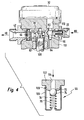
- a fuel system carries the whole Reference numeral 10. It includes a low-pressure region 12 and a high pressure area 14.
- the low-pressure fuel line 22 leads to a High pressure pump 30. This will not be closer to here shown manner of the camshaft a Internal combustion engine (not shown) driven.
- a High pressure pump 30 In the High pressure pump 30 is a 1-piston high pressure pump. Upstream of the high pressure pump 30th are still in the low pressure fuel line 22 Pressure damper 32 and a suction valve 34 is arranged.
- a second branch line 36 Between the filter 24 and the pressure damper 32 branches from the Low pressure fuel line 22 a second branch line 36, in which a low-pressure regulator 38 is arranged.
- the second branch line 36 also leads to the reservoir 16. From the high pressure pump 30 performs a leakage line 40th to the second branch 36.
- Fuel injection valves 48 connected to the Fuel in a combustion chamber, not shown Inject internal combustion engine.
- the pressure in the Fuel manifold 46 is from a pressure sensor 50 detected.
- a throttle (not shown) may be provided.
- the throttle avoids Pressure oscillations and unwanted noise in the high pressure area 14.
- Quantity control valve 52 is not one of in FIG shown control unit, which in turn receives signals from the pressure sensor 50. In this way will be a closed loop for the regulation of Pressure in the high pressure region 14 of the fuel system 10th created.
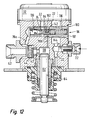
- FIG. 2 shows a first embodiment of a Pressure relief valve 56 according to the invention, which in a housing 58 of the high-pressure pump 30 is integrated.
- Housing 58 By doing Housing 58, a delivery chamber 60 is provided, which on a Side bounded by a piston 62 of the high pressure pump 30 becomes.
- the piston 62 oscillates in a bore 64 of the Housing 58.
- the drive of the piston 62 is not in Fig. 2 shown.
- the oscillating movement of the piston 62 is indicated by a double arrow 66 in Fig. 2.
- the low-pressure fuel line opens 22 with a suction valve 34.
- the delivery chamber 60 also leaves the third branch line 54, in which the quantity control valve 52 is arranged.
- the high pressure fuel line 42 with the check valve 44 from.
- the fourth branch 70 consists of sections 70a and 70b.
- the pressure limiting valve 56 is in the in FIG illustrated embodiment as a ball valve educated. However, other can also be used according to the invention Forms of poppet valves and also slide valves used become.
- a valve seat 72 is prepared, which with a formed as a ball in the valve member 74th cooperates in a conventional manner.
- a spring 76 which is supported at one end against the housing 58 and the other end against the valve member 74 is supported determined by its bias the opening pressure of Pressure relief valve 56.
- the spring 76 is in a Spring chamber 78 of the housing 58 housed.
- Pressure relief valve 56 according to the invention also at Occurrence of pressure pulsations during the delivery stroke of High-pressure fuel pump 30 is closed. Thereby finds the Pressure build-up in normal operation of the internal combustion engine desired instead. Only when during the suction stroke the High pressure pump 30, the pressure in the high pressure fuel line 42 the opening pressure of Pressure relief valve 56 exceeds that opens Pressure relief valve 56 and thus allows a Pressure reduction in the high pressure fuel line 42.
- a first line 80 shows the path of the piston 62 in the Bore 64.
- the movement from bottom dead center (UT) to the bottom Top dead center (TDC) is called delivery stroke and is characterized in Figure 3 by the double arrow 82.
- the path of the piston from the TDC to the TDC becomes the suction stroke 84 designated.
- a dashed third line 88 is shown, which represents the pressure in the high-pressure fuel line 42 behind the check valve 44 and in the portion 70 a of the fourth branch line 70. It can be clearly seen in FIG. 3 that the line 88, that is to say the pressure in the high-pressure fuel line 42, follows the pressure in the delivery chamber 60 (second line 86) during the delivery stroke 82, even if the pressure is the opening pressure P DBV of the pressure-limiting valve 56 exceeds. Only when during the suction stroke 84, the pressure in the delivery chamber 60 drops sharply (see the second solid line 86), a pressure difference between the pressure in the high-pressure fuel line 42 and the delivery chamber 60 can form.
- the pressure in the high-pressure fuel line 42 during the intake stroke remains equal to the opening pressure P DBV of the pressure relief valve 56, while the pressure in the delivery chamber 60, however, drops sharply.
- the pressure limiting valve 56 prevents the occurrence of impermissibly high pressures during the suction stroke in that the amount of fuel delivered into the fuel manifold 46 during the delivery stroke is released back into the delivery chamber 60 during the intake stroke.
- the portion 70a of the fourth branch 70 is called Stepped bore executed.
- this stepped bore is the Seat sleeve 102 is pressed so that it is attached to a paragraph of Stepped bore is fixed in the axial direction.
- the Pen holder 106 is also in the stepped bore pressed in and then when the between Penholder 106 and valve member 74 arranged spring 76th has sufficient preload, in this position welded.
- the weld is in Figure 5 with the Reference numeral 109 provided.
- a pressure relief valve 56 according to the invention no direct connection between seat sleeve 102 and Pen holder 106. So that the spring 76 is not laterally can dodge, is on the spring holder 106, a support pin 112nd intended.
- the third branch line 54 and the section 70b of the fourth branch 70 lie on one common axis, so that these holes in one Clamping can be made and no additional Sealing point is created to the outside.
- the suction valve 34 is as Plate valve executed with a valve plate 111.
- the Valve plate 111 is replaced by a spring 76 against a Valve seat 115 of the suction valve 34 is pressed.
- the quantity control valve 52 is at this and the hereinafter described embodiments suction side arranged and lifted, if it is controlled accordingly, during the delivery stroke 82, the valve plate 111 with the help a plunger 113 from the valve seat 72 from. If the Valve plate 111 does not rest on the valve seat 72 is the suction valve 34 is opened.
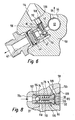
- FIG. 6 is another embodiment of a illustrated pressure relief valve according to the invention. Of the constructive structure of this pressure relief valve. 6 corresponds essentially to that shown in FIG Pressure relief valve 56. However, the Installation situation in the embodiment according to FIG. 6 something else. In this embodiment, the Low pressure fuel line 22, the suction valve 34 and the Quantity control valve 52 not shown.
- the pressure relief valve 56 is in one Stepped bore 114 of the housing 58 is arranged.
- the Stepped bore 114 is perpendicular to High pressure fuel line 42, which in the delivery room opens, arranged.
- the stepped bore 114 in turn opens in the fourth branch 70.
- the spring holder 106 as soon as he has reached the correct position, by a weld 109 firmly connected to the housing 58.
- FIG. 7 shows a cross section through the housing 58 at the level of the delivery chamber 60.
- the piston 62 which in the bore 64th is guided, visible.
- the low pressure fuel line 22 is in this Presentation not visible.
- the arrangement shown is a very compact design possible because the pressure relief valve according to the invention (56) at the same height as the delivery chamber (60) (not shown) is arranged.
- separating piston 90 is between the Delivery chamber 60 and the valve member 74 in a housing 58th sealingly guided separating piston 90 is provided.
- the Separating piston 90 includes a plunger 92, which in the Spring chamber 78 protrudes.
- an additional spring 96 tensioned is between the separating piston 90 and a Spring plate 94, which rests on the valve member 74.
- the auxiliary spring 96 causes the plunger 92 not on the spring plate 94th rests when on both sides of the separating piston 90, the in the spring chamber 78 and in the section 70b of the fourth Branch line 70 and the delivery chamber 60, the same pressure prevails.
- the spring chamber 78 is in this embodiment with a non-pressurized leakage line 98 or with the Low pressure fuel line 22 connected.
- the auxiliary spring 96 During the suction stroke 84 of the High pressure pump 30 presses the auxiliary spring 96 the separating piston 90 in Figure 7 to the left, so that he from the spring plate 94th takes off.
- a decoupling from the separating piston 90th and valve member 74 made so that during the Suction stroke slight pressure fluctuations in the delivery chamber 60th the high pressure pump is not detrimental to the Control behavior of the pressure relief valve 56 impact can.
- the diameter of the separating piston 90 and the Valve seat 72 may also be a hydraulic Reinforcement of the separating piston 90 on the valve member 74th applied hydraulic force during the delivery stroke be achieved.
- the auxiliary spring 96 can also in the section 70b of fourth branch line 70 are arranged (see the arrow 100), so that they are on the one hand against the housing 58 and on the other hand supported against the separating piston 90 and this permanently in contact with the spring plate 94 holds.
- This Measure is the pressure build-up in the delivery chamber 60 and thus also in the high pressure fuel line 42 during the Delivery of the high-pressure pump 30 speeds.
- the preassembled and adjusted pressure relief valve 56 is placed in the stepped bore portion 70a pressed the fourth branch and by a Closure plug 120, which is welded to the housing 58 is sealed to the environment.
- a Closure plug 120 In the stopper 120 are at the pressure limiting valve 56 facing Milled front side grooves 122, which is a hydraulic Connection between the section 70b of the fourth Branch line leading into the delivery chamber (not shown) opens, and allow the separating piston 90.
- the diameter the separating piston 90 is dimensioned so that the Pressure relief valve 56 does not open when pressure surges or pressure increases in the delivery chamber (not shown in FIG. 8) during the delivery stroke of the high-pressure pump 30 arise.
- the pressure relief valve according to the invention has the following Main functions:
- the system pressure is the Fuel injection system in overrun mode of the engine limited when the pressure in the fuel rail 46 by the heating of the fuel by the engine heat increases.
- the system pressure is the Fuel injection system also limited.
- FIG. 9 is another embodiment of a Pressure relief valve 56 according to the invention in section shown.
- the embodiment according to FIG. 9 has Parallels to the embodiment according to FIG. 2, see FIG that only described the developments of the invention and otherwise to the above to Figure 2 said is referenced.
- the embodiment according to FIG. 9 closes at the valve seat 72 is a cylindrical Guide portion 124, the valve member 74 in axial Direction leads as soon as this lifted off the valve seat 72 Has.
- the diameter of the guide portion 124 and the Diameter of the formed as a ball valve member 74th are so coordinated that between Valve member 74 and guide portion 124 is an annular Throttle gap 126 forms.
- the mode of action of this Embodiment of an inventive Pressure relief valve is as follows:
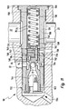
- the pressure limiting valve according to FIG. 11 consists of a Valve housing 128, which has a stepped center hole 130th having. At its outer diameter has the Valve housing 128 has a first sealing bead 132, a second sealing bead 134 and a third sealing bead 136 on.
- a seat sleeve 102 in which the valve seat 72 is formed is pressed in.
- the axial position of the seat sleeve 102 in the center hole 130 is replaced by a paragraph of Center hole 130 and a shoulder in the seat sleeve 102nd clearly defined.
- a Fuel strainer 144 attached, which dirt in the Fuel from the sealing seat 72 and the valve member 74th keeps.
- the pressure limiting valve 56 is as follows in FIG the high-pressure pump 130 integrated.
- the fourth branch is the left side of the Valve member 74 with the high pressure region of the high pressure pump 30 prevailing pressure of the fuel applied.
- a radial bore 146 in the intermediate piece with the in Delivery chamber 60 of the high pressure pump 30 prevailing pressure applied.
- the intermediate piece 142 has two sealing beads 148 on.
- a Circumferential groove present along with the center hole 130 of the valve housing 128 has a circumferential annular space forms.
- the portion 70b in the valve housing 128 is so positioned so that it opens into this annulus.
- the radial bore 146 positioned so that they in the Annulus opens, so that regardless of the angular position of Section 70b and the radial bore 146 to each other the hydraulic connection between the portion 70b and the Radial bore 146 is always guaranteed.
- the Radial bore 146 opens into a blind hole running Center bore 150 of the intermediate piece 142 in the Separating piston 152 is guided sliding and sealing. Of the Separating piston 152 is supported at one end to the Spring plate 94 from.
- the separating piston 152 transmits a the pressure in the delivery chamber 60 proportional force on the Spring plate 94 and thus causes the opening pressure the pressure limiting valve 56 during the delivery stroke, when namely, the pressure in the delivery chamber is also high, increased so that the unwanted opening operations during of the delivery stroke are suppressed.
- valve housing 128 Between the third sealing bead 136 and a collar 156 of the Valve housing 128 is provided a circumferential groove 158, so that fuel in a section of the low-pressure line 22 in the housing 58 of the high-pressure pump 30 to the valve housing 128 can flow around and to a not shown Pressure damper 32 can continue to flow.
- the valve housing 128 is welded to the collar 58 at the collar 58. This 11 is a stylized weld 160 in FIG indicated.
- FIG. 12 the pressure limiting valve 56 is according to FIG. 11 is shown in a high-pressure pump 30. From this Representation can be the hydraulic connection of the Pressure relief valve 56 in the high pressure pump 30 better detect. Not all components of FIG Pressure limiting valve 56 provided with reference numerals to the clarity of Figure 12 is not too affect.
- the diameter of the separating piston 152 may depend on the pressure in the delivery chamber 60 Contact pressure of the spring plate 94 on the valve member 64th be set.
- the spring plate 94 has at least one longitudinal groove 162, through the fuel, which when open Pressure limiting valve 56 from the section 70 a in the Pressure relief valve 56 flows in the Nidertik-fuel line 22 can be dissipated.
- the Low-pressure fuel line 22 opens at this Embodiment in the spring chamber 78th
- the intermediate piece is fixed with the sealing beads 148 and liquid-tight pressed into the center hole 130. ever after how deep the intermediate piece in the center hole 130th is pressed, there is a bias of the spring 76th and thus the opening pressure of the pressure limiting valve 56 one. After setting the opening pressure is the Center hole 130 closed by a cover 164. Of the Lid 164 may be welded to the housing 58.
- the exemplary embodiments according to FIGS. 7, 8, 11, 12, and 13 are different from the others Embodiments in that the pressure reduction is not to the delivery chamber 60, but in the low-pressure fuel line 22nd
Abstract
Description
- Figur 1:
- eine Prinzipdarstellung eines Kraftstoffsystems mit einer Kraftstoffpumpe, an die ein Druckbegrenzungsventil angebaut ist;
- Figur 2:
- einen Schnitt durch einen Bereich der Hochdruckpumpe und ein erstes Ausführungsbeispiel eines Druckbegrenzungsventils von Figur 1;
- Figur 3:
- ein Diagramm, in dem der Druckverlauf im Förderraum und im Hochdruckbereich des Kraftstoffsystems über der Zeit dargestellt ist und
- Figuren 4 bis 13:
- weitere Ausführungsbeispiele erfindungsgemäßer Druckbegrenzungsventile.
Claims (28)
- Druckbegrenzungsventil für ein Kraftstoffsystem (10) einer Brennkraftmaschine, mit einer Druckseite und mit einem Auslass, mit einem gegen einen Ventilsitz (72) vorgespannten Ventilglied (74), wobei die Druckseite mit dem in einem Hochdruckbereich (14) des Kraftstoffsystems (10) herrschenden Druck beaufschlagt wird, wobei das Ventilglied (74) ab einer bestimmten zwischen Einlass und Auslass vorhandenen Druckdifferenz diese hydraulisch verbindet, dadurch gekennzeichnet, dass der Auslass des Druckbegrenzungsventils (56) mit einem Förderraum (60) einer Hochdruckpumpe (30) des Kraftstoffsystems (10) hydraulisch in Verbindung steht.
- Druckbegrenzungsventil nach Anspruch 1, dadurch gekennzeichnet, dass das Druckbegrenzungsventil (56) als Sitzventil oder als Schieberventil ausgeführt ist.
- Druckbegrenzungsventil nach Anspruch 1 oder 2, dadurch gekennzeichnet, dass das Druckbegrenzungsventil (56) ein Gehäuse (58) mit einem Ventilsitz (72) und einer Federkammer (78) aufweist, dass in der Federkammer (78) eine Feder (76) vorgesehen ist, die sich einenends gegen das Gehäuse (58) und anderenends gegen das Ventilglied (74) abstützt, und dass die Federkammer (78) mit dem Auslass (70b) hydraulisch in Verbindung steht. (Figur 2)
- Druckbegrenzungsventil nach einem der vorhergehenden Ansprüche, dadurch gekennzeichnet, dass das Druckbegrenzungsventil (56) einen Federhalter (106) aufweist, und dass zwischen Federhalter (106) und Ventilsitz (72) eine Feder (76) vorgesehen ist, die sich einenends gegen den Federhalter (106) und anderenends gegen das Ventilglied (74) abstützt (Figur 4).
- Druckbegrenzungsventil nach Anspruch 4, dadurch gekennzeichnet, dass der Federhalter (106) mit dem Ventilsitz (72) verbunden ist. (Figur 4, 8)
- Druckbegrenzungsventil nach Anspruch 4, dadurch gekennzeichnet, dass der Federhalter (106) in einer Bohrung (70a, 114) des Gehäuses (58, 128) befestigt ist. (Figur 8)
- Druckbegrenzungsventil nach Anspruch 6, dadurch gekennzeichnet, dass der Federhalter (106) in der Bohrung (70a, 114) eingepresst und/oder eingeschweißt ist. (Figur 5 und 6)
- Druckbegrenzungsventil nach einem der Ansprüche 4 bis 7, dadurch gekennzeichnet, dass der Federhalter (106) einen Stützdorn (112) aufweist. (Figur 5 und 6)
- Druckbegrenzungsventil nach einem der Ansprüche 3 bis 8, dadurch gekennzeichnet, dass der Ventilsitz (72) in einer Sitzhülse (102) angeordnet ist, und dass die Sitzhülse (102) in einer Bohrung (70a, 114) des Gehäuses (58, 128) befestigt ist. (Figur 5, 6, 11, 12, 13)
- Druckbegrenzungsventil nach Anspruch 9, dadurch gekennzeichnet, dass die Sitzhülse (102) in der Bohrung (70a, 114) eingepresst und/oder eingeschweißt ist. (Figur 5, 6, 11, 13)
- Druckbegrenzungsventil nach einem der Ansprüche 3 bis 10, dadurch gekennzeichnet, dass an den Ventilsitz (72) ein Führungsabschnitt (124) anschließt, und dass sich zwischen dem Führungsabschnitt (124) und dem Ventilglied (74) ein Drosselspalt (126) ausbildet. (Figur 9)
- Druckbegrenzungsventil nach einem der Ansprüche 3 bis 11, dadurch gekennzeichnet, dass an den Ventilsitz (72) ein Führungsabschnitt (124) anschließt, und dass sich zwischen dem Führungsabschnitt (124) und dem Federteller (94) ein Drosselspalt (126) ausbildet. (Figur 10)
- Druckbegrenzungsventil nach einem der Ansprüche 3 bis 12, dadurch gekennzeichnet, dass zwischen Federkammer (78) und Auslass (70b) ein dichtend geführter Trennkolben (90) vorgesehen ist, und dass der Trennkolben (90, 152) mindestens mittelbar auf dem Ventilglied (74) aufliegt, wenn zwischen Auslass (70b) und Federkammer (78) eine vorgegebene Druckdifferenz herrscht. (Figur 7, 8, 11, 12, und 13)
- Druckbegrenzungsventil nach Anspruch 13, dadurch gekennzeichnet, dass der Trennkolben (90) in dem Gehäuse (58, 128) dichtend geführt ist (Figur 7).
- Druckbegrenzungsventil nach Anspruch 14, dadurch gekennzeichnet, dass der Trennkolben (90) in dem Federhalter (106) dichtend geführt ist (Figur 8).
- Druckbegrenzungsventil nach einem der Ansprüche 13 bis 15, dadurch gekennzeichnet, dass zwischen Trennkolben (90) und Ventilglied (74) eine vorgespannte Zusatzfeder (96) vorgesehen ist.
- Druckbegrenzungsventil nach einem der Ansprüche 3 bis 16, dadurch gekennzeichnet, dass zwischen Feder (76) und/oder Zusatzfeder (96) und Ventilglied (74) ein Federteller (94) vorgesehen ist.
- Druckbegrenzungsventil nach einem der Ansprüche 16 oder 17, dadurch gekennzeichnet, dass die Zusatzfeder (96) in der Saugphase den Trennkolben (90) vom Ventilglied (74) abhebt.
- Druckbegrenzungsventil nach Anspruch 18, dadurch gekennzeichnet, dass die Zusatzfeder (96) den Trennkolben (90) in Anlage an dem Ventilglied (74) hält.
- Druckbegrenzungsventil nach einem der Ansprüche 13 bis 19, dadurch gekennzeichnet, dass der Trennkolben (152) mit dem Förderraum (60) hydraulisch in Verbindung steht. (Figur 8)
- Druckbegrenzungsventil nach einem der Ansprüche 13 bis 15, dadurch gekennzeichnet, dass in der Federkammer (78) ein Zwischenstück (142) mit einer Radialbohrung (146) und einer Zentrumsbohrung (150) vorgesehen ist, dass der Trennkolben (152) in der Zentrumsbohrung (150) dichtend geführt ist, dass die Radialbohrung (146) und die Zentrumsbohrung (150) hydraulisch in Verbindung stehen, dass die Radialbohrung (146) über den Abschnitt (70b) der vierten Zeigleitung (70) mit dem Förderraum (60) hydraulisch in Verbindung steht, und dass die Auslassseite des des Druckbegrenzungsventils (56) mit der Niederdruckkraftstoffleitung (22) hydraulisch in Verbindung steht. (Figur 11, 12 und 13)
- Druckbegrenzungsventil nach Anspruch 21, dadurch gekennzeichnet, dass in dem Zwischenstück (142) mindestens ein Stift ((140) geführt wird, und dass der mindestens eine Stift (140) die Kraft der Feder 76) auf den Federteller (4) überträgt. (Figur 11)
- Druckbegrenzungsventil nach einem der Ansprüche 3 bis 22, dadurch gekennzeichnet, dass die Federkammer (78) mit einer Leckageleitung (98) in Verbindung steht.
- Druckbegrenzungsventil nach einem der Ansprüche 3 bis 23, dadurch gekennzeichnet, dass das Gehäuse (128) mehrere umlaufende Dichtwülste (132, 134, 136) aufweist. (Figur 11, 12 und 13)
- Druckbegrenzungsventil nach einem der Ansprüche 3 bis 24, dadurch gekennzeichnet, dass das Gehäuse (128) mit der Hochdruckpumpe (30) verschweißt (160) ist. (Figur 12)
- Kraftstoffsystem (10) zum Zuliefern von Kraftstoff (18) für eine Brennkraftmaschine, mit einem Vorratsbehälter (16), mit einer ersten Kraftstoffpumpe (20), welche eingangsseitig mit dem Vorratsbehälter (16) verbunden ist, mit einer Hochdruckpumpe (30), welche eingangsseitig über eine Kraftstoffverbindung (22) mit der ersten Kraftstoffpumpe (20) verbunden ist, und mit einem Druckbegrenzungsventil (56), welches den Druck in einer Kraftstoffleitung (42, 46) auf der Ausgangsseite der Hochdruckpumpe (30) begrenzt, dadurch gekennzeichnet, dass das Druckbegrenzungsventil (56) nach einem der Ansprüche 1 bis 18 ausgebildet ist.
- Kraftstoffsystem (10) nach Anspruch 25, dadurch gekennzeichnet, dass die Hochdruckpumpe (30) eine 1-Zylinder-Kolbenpumpe umfasst.
- Kraftstoffsystem (10) nach einem der Ansprüche 25 oder 26, dadurch gekennzeichnet, dass das Druckbegrenzungsventil (56) an die Hochdruckpumpe (30) angebaut, vorzugsweise in diese integriert ist.
Applications Claiming Priority (4)
| Application Number | Priority Date | Filing Date | Title |
|---|---|---|---|
| DE10247976 | 2002-10-15 | ||
| DE10247976 | 2002-10-15 | ||
| DE10327411 | 2003-06-18 | ||
| DE10327411.1A DE10327411B4 (de) | 2002-10-15 | 2003-06-18 | Druckbegrenzungsventil sowie Kraftstoffsystem mit einem solchen Druckbegrenzungsventil |
Publications (2)
| Publication Number | Publication Date |
|---|---|
| EP1411238A1 true EP1411238A1 (de) | 2004-04-21 |
| EP1411238B1 EP1411238B1 (de) | 2006-01-11 |
Family
ID=32043969
Family Applications (1)
| Application Number | Title | Priority Date | Filing Date |
|---|---|---|---|
| EP20030015658 Expired - Lifetime EP1411238B1 (de) | 2002-10-15 | 2003-07-17 | Druckbegrenzungsventil für ein Kraftstoffeinspritzsystem |
Country Status (4)
| Country | Link |
|---|---|
| EP (1) | EP1411238B1 (de) |
| JP (1) | JP4488486B2 (de) |
| DE (1) | DE50302164D1 (de) |
| ES (1) | ES2256621T3 (de) |
Cited By (28)
| Publication number | Priority date | Publication date | Assignee | Title |
|---|---|---|---|---|
| EP1701032A1 (de) * | 2005-03-01 | 2006-09-13 | Jtekt Corporation | Rückschlagventil für Kraftstoffeinspritzpumpe |
| US20070110603A1 (en) * | 2005-11-16 | 2007-05-17 | Hitachi, Ltd. | High-pressure fuel pump |
| WO2009021884A1 (de) * | 2007-08-16 | 2009-02-19 | Robert Bosch Gmbh | Kraftstoffhochdruckpumpe |
| EP2011998A3 (de) * | 2007-07-06 | 2009-03-04 | Denso Corporation | Kraftstoffpumpe für Verbrennungsmotor |
| WO2010060834A1 (de) * | 2008-11-28 | 2010-06-03 | Continental Automotive Gmbh | Hochdruckpumpe |
| WO2010106037A1 (de) * | 2009-03-20 | 2010-09-23 | Continental Automotive Gmbh | Druckentlastungsvorrichtung eines einspritzsystems sowie verfahren zur druckentlastung eines einspritzsystems |
| EP2055929A3 (de) * | 2007-11-01 | 2010-12-08 | Hitachi Ltd. | Hochdruckflüssigkeitsförderpumpe |
| WO2011003789A1 (en) * | 2009-07-08 | 2011-01-13 | Delphi Technologies Holding S.À.R.L. | A pump unit |
| US20110259302A1 (en) * | 2008-10-27 | 2011-10-27 | Hyundai Heavy Industries Co., Ltd. | Apparatus for preventing cavitation damage to a diesel engine fuel injection pump |
| US8132558B2 (en) | 2009-12-01 | 2012-03-13 | Stanadyne Corporation | Common rail fuel pump with combined discharge and overpressure relief valves |
| WO2012095718A3 (en) * | 2011-01-12 | 2012-09-07 | Toyota Jidosha Kabushiki Kaisha | High-pressure pump |
| EP2497939A1 (de) | 2011-03-08 | 2012-09-12 | Hitachi Automotive Systems, Ltd. | Hochdruckbrennstoffförderpumpe |
| DE102011005286A1 (de) | 2011-03-09 | 2012-09-13 | Continental Automotive Gmbh | Verfahren zum Betreiben einer Brennkraftmaschine und Brennkraftmaschine |
| WO2012123131A1 (de) * | 2011-03-14 | 2012-09-20 | Robert Bosch Gmbh | Ventileinrichtung, insbesondere auslassventil einer kraftstoff-hochdruckpumpe einer brennkraftmaschine |
| CN102734022A (zh) * | 2011-03-31 | 2012-10-17 | 株式会社电装 | 高压泵 |
| WO2013177021A1 (en) * | 2012-05-23 | 2013-11-28 | Caterpillar Inc. | Fuel system having flow-disruption reducer |
| CN103967670A (zh) * | 2013-02-04 | 2014-08-06 | 辽宁新风企业集团有限公司 | 一种高压油泵用油阀部件 |
| WO2014206639A1 (de) * | 2013-06-28 | 2014-12-31 | Robert Bosch Gmbh | Hydraulische baugruppe für ein kraftstoffsystem einer brennkraftmaschine |
| WO2015055411A1 (de) * | 2013-10-15 | 2015-04-23 | Continental Automotive Gmbh | Druckbegrenzungsventil für ein kraftstoffeinspritzsystem und kraftstoffeinspritzsystem |
| EP2780576A4 (de) * | 2011-11-17 | 2015-08-12 | Stanadyne Corp | Zusätzliches druckentlastungsventil bei einer einzelkolbenkraftstoffpumpe |
| WO2017063990A1 (de) * | 2015-10-14 | 2017-04-20 | Continental Automotive Gmbh | Bauelement, insbesondere kraftstoffhochdruckpumpe, für ein kraftstoffeinspritzsystem |
| EP3088726A4 (de) * | 2013-12-27 | 2017-08-30 | Hitachi Automotive Systems, Ltd. | Hochdruckbrennstoffförderpumpe |
| EP3252300A4 (de) * | 2015-01-26 | 2018-08-08 | Hitachi Automotive Systems, Ltd. | Ventilmechanismus und hochdruckkraftstoffförderpumpe damit |
| EP3296558A4 (de) * | 2015-05-12 | 2018-12-19 | Hitachi Automotive Systems, Ltd. | Hochdruckbrennstoffpumpe |
| CN110700969A (zh) * | 2018-07-10 | 2020-01-17 | 罗伯特·博世有限公司 | 低温燃料的燃料输送装置及其运行方法 |
| CN111868370A (zh) * | 2018-01-17 | 2020-10-30 | 罗伯特·博世有限公司 | 用于低温燃料的燃料输送装置 |
| EP3218595B1 (de) * | 2014-11-10 | 2020-11-11 | Robert Bosch GmbH | Kraftstoff-hochdruckpumpe für ein kraftstoffsystem für eine brennkraftmaschine |
| CN114502833A (zh) * | 2019-11-13 | 2022-05-13 | 日立安斯泰莫株式会社 | 燃料供给泵 |
Families Citing this family (36)
| Publication number | Priority date | Publication date | Assignee | Title |
|---|---|---|---|---|
| JP4069913B2 (ja) * | 2004-09-10 | 2008-04-02 | 株式会社デンソー | 蓄圧式燃料噴射システムに用いられる継手部材の接合方法および取付ステーの接合方法 |
| DE102004063075B4 (de) * | 2004-12-28 | 2015-11-26 | Robert Bosch Gmbh | Kraftstoff-Hochdruckpumpe für eine Brennkraftmaschine mit einem Stufenkolben und einem Mengensteuerventil |
| JP2007120492A (ja) * | 2005-09-29 | 2007-05-17 | Denso Corp | 高圧燃料ポンプ |
| DE102007016134A1 (de) * | 2006-04-25 | 2007-11-08 | Robert Bosch Gmbh | Kraftstoff-Hochdruckpumpe |
| JP4437552B2 (ja) | 2006-05-26 | 2010-03-24 | 株式会社デンソー | 高圧燃料ポンプ |
| JP5176948B2 (ja) * | 2008-12-26 | 2013-04-03 | 株式会社デンソー | 燃料供給装置、及び、高圧ポンプ |
| JP5252314B2 (ja) * | 2008-12-26 | 2013-07-31 | 株式会社デンソー | 高圧ポンプ |
| JP2010156256A (ja) * | 2008-12-26 | 2010-07-15 | Denso Corp | 高圧ポンプ |
| JP5176947B2 (ja) * | 2008-12-26 | 2013-04-03 | 株式会社デンソー | 高圧ポンプ |
| JP5196320B2 (ja) * | 2008-12-26 | 2013-05-15 | 株式会社デンソー | 高圧ポンプ |
| JP5196321B2 (ja) * | 2008-12-26 | 2013-05-15 | 株式会社デンソー | 燃料供給装置、及び、高圧ポンプ |
| JP5344307B2 (ja) * | 2009-12-11 | 2013-11-20 | 株式会社デンソー | 高圧ポンプ |
| JP5529615B2 (ja) * | 2010-04-08 | 2014-06-25 | 株式会社デンソー | 高圧ポンプ |
| JP5472737B2 (ja) * | 2010-04-08 | 2014-04-16 | 株式会社デンソー | リリーフ弁及びそれを用いた高圧ポンプ |
| JP5472395B2 (ja) * | 2010-06-29 | 2014-04-16 | 株式会社デンソー | 高圧ポンプ |
| JP5158219B2 (ja) * | 2010-06-29 | 2013-03-06 | 株式会社デンソー | リリーフ弁及びこれを用いた高圧ポンプ |
| DK2495431T3 (da) * | 2011-03-04 | 2014-02-03 | Omt Ohg Torino S P A | Hydraulisk pumpe, i særdeleshed en brændstofpumpe |
| JP5472751B2 (ja) * | 2011-03-30 | 2014-04-16 | 株式会社デンソー | 高圧ポンプ |
| JP5505732B2 (ja) * | 2011-03-31 | 2014-05-28 | 株式会社デンソー | 高圧ポンプ |
| US9181944B2 (en) | 2011-03-31 | 2015-11-10 | Denso Corporation | High pressure pump having unitary discharge and relief valve |
| JP5382548B2 (ja) | 2011-03-31 | 2014-01-08 | 株式会社デンソー | 高圧ポンプ |
| JP5729607B2 (ja) * | 2011-09-27 | 2015-06-03 | 株式会社デンソー | 高圧ポンプ |
| JP2013241835A (ja) * | 2012-05-17 | 2013-12-05 | Nippon Soken Inc | 高圧燃料ポンプのリリーフ弁 |
| EP2728163B1 (de) * | 2012-10-30 | 2016-08-17 | Delphi International Operations Luxembourg S.à r.l. | Ventilanordnung |
| DE102013204563A1 (de) * | 2013-03-15 | 2014-09-18 | Robert Bosch Gmbh | Kraftstoff-Hochdruckpumpe mit einem zwischen einem Förderraum und einem Auslass angeordneten Auslassventil |
| DE102013216817A1 (de) * | 2013-08-23 | 2015-02-26 | Continental Automotive Gmbh | Pumpenanordnung und System für ein Kraftfahrzeug |
| JP6165674B2 (ja) * | 2014-05-28 | 2017-07-19 | 日立オートモティブシステムズ株式会社 | 高圧燃料供給ポンプ |
| JP2016133056A (ja) * | 2015-01-20 | 2016-07-25 | 株式会社デンソー | 高圧ポンプ及びその製造方法 |
| JP6369337B2 (ja) * | 2015-01-20 | 2018-08-08 | 株式会社デンソー | 高圧ポンプ及びその製造方法 |
| JP6317701B2 (ja) * | 2015-04-10 | 2018-04-25 | 株式会社デンソー | 高圧ポンプ |
| DE102015215186B3 (de) * | 2015-08-10 | 2016-12-15 | Continental Automotive Gmbh | Kraftstoffhochdruckpumpe |
| US20190301414A1 (en) * | 2016-05-27 | 2019-10-03 | Hitachi Automotive Systems, Ltd. | High-Pressure Fuel Supply Pump |
| JP6649483B2 (ja) * | 2016-06-29 | 2020-02-19 | 日立オートモティブシステムズ株式会社 | 高圧燃料供給ポンプ |
| JP2018178969A (ja) * | 2017-04-21 | 2018-11-15 | 日立オートモティブシステムズ株式会社 | 高圧燃料供給ポンプ |
| DE102019203967A1 (de) | 2018-03-27 | 2019-10-02 | Keihin Corporation | Ventileinheit-befestigungsstruktur und fluidpumpe welche selbige verwendet |
| JP7084753B2 (ja) * | 2018-03-27 | 2022-06-15 | 日立Astemo株式会社 | 弁ユニット固定構造 |
Citations (6)
| Publication number | Priority date | Publication date | Assignee | Title |
|---|---|---|---|---|
| US4064855A (en) * | 1976-02-17 | 1977-12-27 | Johnson Lloyd E | Pressure relief at fuel injection valve upon termination of injection |
| US4409939A (en) * | 1980-02-07 | 1983-10-18 | Robert Bosch Gmbh | Fuel injection pump for internal combustion engines |
| DE3812199A1 (de) * | 1988-04-13 | 1989-10-26 | Daimler Benz Ag | Vorrichtung zur begrenzung der vollasteinspritzmenge bei einer aufgeladenen luftverdichtenden einspritzbrennkraftmaschine |
| US6293253B1 (en) * | 1996-03-28 | 2001-09-25 | Siemens Aktiengesellschaft | Control for a fluid pressure supply system, particularly for high pressure in a fuel injection system |
| US20010029925A1 (en) * | 1999-12-14 | 2001-10-18 | Ferry William R. | Controlled nozzle injection method and apparatus |
| EP0728940B1 (de) * | 1995-02-21 | 2002-01-09 | Siemens Automotive Corporation | Kombiniertes Anlasser-, Bypass- und Sicherheitsdruckentladungsventil für ein Brennstoffsystem |
-
2003
- 2003-07-17 EP EP20030015658 patent/EP1411238B1/de not_active Expired - Lifetime
- 2003-07-17 ES ES03015658T patent/ES2256621T3/es not_active Expired - Lifetime
- 2003-07-17 DE DE50302164T patent/DE50302164D1/de not_active Expired - Lifetime
- 2003-10-14 JP JP2003354288A patent/JP4488486B2/ja not_active Expired - Lifetime
Patent Citations (6)
| Publication number | Priority date | Publication date | Assignee | Title |
|---|---|---|---|---|
| US4064855A (en) * | 1976-02-17 | 1977-12-27 | Johnson Lloyd E | Pressure relief at fuel injection valve upon termination of injection |
| US4409939A (en) * | 1980-02-07 | 1983-10-18 | Robert Bosch Gmbh | Fuel injection pump for internal combustion engines |
| DE3812199A1 (de) * | 1988-04-13 | 1989-10-26 | Daimler Benz Ag | Vorrichtung zur begrenzung der vollasteinspritzmenge bei einer aufgeladenen luftverdichtenden einspritzbrennkraftmaschine |
| EP0728940B1 (de) * | 1995-02-21 | 2002-01-09 | Siemens Automotive Corporation | Kombiniertes Anlasser-, Bypass- und Sicherheitsdruckentladungsventil für ein Brennstoffsystem |
| US6293253B1 (en) * | 1996-03-28 | 2001-09-25 | Siemens Aktiengesellschaft | Control for a fluid pressure supply system, particularly for high pressure in a fuel injection system |
| US20010029925A1 (en) * | 1999-12-14 | 2001-10-18 | Ferry William R. | Controlled nozzle injection method and apparatus |
Cited By (57)
| Publication number | Priority date | Publication date | Assignee | Title |
|---|---|---|---|---|
| EP1701032A1 (de) * | 2005-03-01 | 2006-09-13 | Jtekt Corporation | Rückschlagventil für Kraftstoffeinspritzpumpe |
| US9291162B2 (en) | 2005-11-16 | 2016-03-22 | Hitachi, Ltd. | High-pressure fuel pump |
| US20070110603A1 (en) * | 2005-11-16 | 2007-05-17 | Hitachi, Ltd. | High-pressure fuel pump |
| EP1788231A1 (de) | 2005-11-16 | 2007-05-23 | Hitachi, Ltd. | Hochdruck-Kraftstoffpumpe |
| US20160160825A1 (en) * | 2005-11-16 | 2016-06-09 | Hitachi, Ltd. | High-Pressure Fuel Pump |
| US10247181B2 (en) | 2005-11-16 | 2019-04-02 | Hitachi, Ltd. | High-pressure fuel pump |
| EP2011998A3 (de) * | 2007-07-06 | 2009-03-04 | Denso Corporation | Kraftstoffpumpe für Verbrennungsmotor |
| CN101338719B (zh) * | 2007-07-06 | 2011-12-07 | 株式会社电装 | 用于内燃机的燃料泵 |
| US8092198B2 (en) | 2007-07-06 | 2012-01-10 | Denso Corporation | Fuel pump for internal combustion engine |
| WO2009021884A1 (de) * | 2007-08-16 | 2009-02-19 | Robert Bosch Gmbh | Kraftstoffhochdruckpumpe |
| EP2055929A3 (de) * | 2007-11-01 | 2010-12-08 | Hitachi Ltd. | Hochdruckflüssigkeitsförderpumpe |
| US8162623B2 (en) | 2007-11-01 | 2012-04-24 | Hitachi, Ltd. | High-pressure liquid supply pump |
| US9200605B2 (en) * | 2008-10-27 | 2015-12-01 | Hyundai Heavy Industries Co., Ltd. | Apparatus for preventing cavitation damage to a diesel engine fuel injection pump |
| US20110259302A1 (en) * | 2008-10-27 | 2011-10-27 | Hyundai Heavy Industries Co., Ltd. | Apparatus for preventing cavitation damage to a diesel engine fuel injection pump |
| WO2010060834A1 (de) * | 2008-11-28 | 2010-06-03 | Continental Automotive Gmbh | Hochdruckpumpe |
| WO2010106037A1 (de) * | 2009-03-20 | 2010-09-23 | Continental Automotive Gmbh | Druckentlastungsvorrichtung eines einspritzsystems sowie verfahren zur druckentlastung eines einspritzsystems |
| CN102362061A (zh) * | 2009-03-20 | 2012-02-22 | 欧陆汽车有限责任公司 | 喷射系统的压力减轻装置以及喷射系统的压力减轻方法 |
| US9016261B2 (en) | 2009-03-20 | 2015-04-28 | Continental Automotive Gmbh | Pressure relief device of an injection system and method for pressure relief of an injection system |
| DE102009014072B4 (de) * | 2009-03-20 | 2014-09-25 | Continental Automotive Gmbh | Common-Rail-Einspritzsystem sowie Verfahren zur Druckentlastung eines Common-Rail-Einspritzsystems |
| WO2011003789A1 (en) * | 2009-07-08 | 2011-01-13 | Delphi Technologies Holding S.À.R.L. | A pump unit |
| EP2287462A1 (de) * | 2009-07-08 | 2011-02-23 | Delphi Technologies Holding S.à.r.l. | Pumpeneinheit |
| US10041457B2 (en) | 2009-07-08 | 2018-08-07 | Delphi Technologies Ip Limited | Pump unit |
| US8132558B2 (en) | 2009-12-01 | 2012-03-13 | Stanadyne Corporation | Common rail fuel pump with combined discharge and overpressure relief valves |
| WO2012095718A3 (en) * | 2011-01-12 | 2012-09-07 | Toyota Jidosha Kabushiki Kaisha | High-pressure pump |
| CN103314210A (zh) * | 2011-01-12 | 2013-09-18 | 丰田自动车株式会社 | 高压泵 |
| US9828958B2 (en) | 2011-03-08 | 2017-11-28 | Hitachi Automotive Systems, Ltd. | High-pressure fuel supply pump |
| EP2497939A1 (de) | 2011-03-08 | 2012-09-12 | Hitachi Automotive Systems, Ltd. | Hochdruckbrennstoffförderpumpe |
| US10788004B2 (en) | 2011-03-08 | 2020-09-29 | Hitachi Automotive Systems, Ltd. | High-pressure fuel supply pump |
| EP3002446A1 (de) | 2011-03-08 | 2016-04-06 | Hitachi Automotive Systems, Ltd. | Hochdruckbrennstoffförderpumpe |
| EP3533992A1 (de) | 2011-03-08 | 2019-09-04 | Hitachi Automotive Systems, Ltd. | Hochdruckbrennstoffförderpumpe |
| DE102011005286A1 (de) | 2011-03-09 | 2012-09-13 | Continental Automotive Gmbh | Verfahren zum Betreiben einer Brennkraftmaschine und Brennkraftmaschine |
| DE102011005286B4 (de) * | 2011-03-09 | 2013-08-14 | Continental Automotive Gmbh | Verfahren zum Betreiben einer Brennkraftmaschine und Brennkraftmaschine |
| WO2012123131A1 (de) * | 2011-03-14 | 2012-09-20 | Robert Bosch Gmbh | Ventileinrichtung, insbesondere auslassventil einer kraftstoff-hochdruckpumpe einer brennkraftmaschine |
| CN102734022A (zh) * | 2011-03-31 | 2012-10-17 | 株式会社电装 | 高压泵 |
| CN102734022B (zh) * | 2011-03-31 | 2014-11-19 | 株式会社电装 | 高压泵 |
| EP2780576A4 (de) * | 2011-11-17 | 2015-08-12 | Stanadyne Corp | Zusätzliches druckentlastungsventil bei einer einzelkolbenkraftstoffpumpe |
| US9644585B2 (en) | 2011-11-17 | 2017-05-09 | Stanadyne Llc | Auxiliary pressure relief valve in single piston fuel pump |
| WO2013177021A1 (en) * | 2012-05-23 | 2013-11-28 | Caterpillar Inc. | Fuel system having flow-disruption reducer |
| CN103967670A (zh) * | 2013-02-04 | 2014-08-06 | 辽宁新风企业集团有限公司 | 一种高压油泵用油阀部件 |
| CN103967670B (zh) * | 2013-02-04 | 2018-11-06 | 辽宁新风企业集团有限公司 | 一种高压油泵用油阀部件 |
| WO2014206639A1 (de) * | 2013-06-28 | 2014-12-31 | Robert Bosch Gmbh | Hydraulische baugruppe für ein kraftstoffsystem einer brennkraftmaschine |
| WO2015055411A1 (de) * | 2013-10-15 | 2015-04-23 | Continental Automotive Gmbh | Druckbegrenzungsventil für ein kraftstoffeinspritzsystem und kraftstoffeinspritzsystem |
| US10215143B2 (en) | 2013-10-15 | 2019-02-26 | Continental Automotive Gmbh | Pressure-limiting valve for a fuel injection system and fuel injection system |
| CN105074195A (zh) * | 2013-10-15 | 2015-11-18 | 大陆汽车有限公司 | 用于燃料喷射系统的限压阀和燃料喷射系统 |
| EP3088726A4 (de) * | 2013-12-27 | 2017-08-30 | Hitachi Automotive Systems, Ltd. | Hochdruckbrennstoffförderpumpe |
| EP3218595B1 (de) * | 2014-11-10 | 2020-11-11 | Robert Bosch GmbH | Kraftstoff-hochdruckpumpe für ein kraftstoffsystem für eine brennkraftmaschine |
| EP3252300A4 (de) * | 2015-01-26 | 2018-08-08 | Hitachi Automotive Systems, Ltd. | Ventilmechanismus und hochdruckkraftstoffförderpumpe damit |
| EP3296558A4 (de) * | 2015-05-12 | 2018-12-19 | Hitachi Automotive Systems, Ltd. | Hochdruckbrennstoffpumpe |
| US10253741B2 (en) | 2015-05-12 | 2019-04-09 | Hitachi Automotive Systems, Ltd | High-pressure fuel pump |
| WO2017063990A1 (de) * | 2015-10-14 | 2017-04-20 | Continental Automotive Gmbh | Bauelement, insbesondere kraftstoffhochdruckpumpe, für ein kraftstoffeinspritzsystem |
| CN111868370A (zh) * | 2018-01-17 | 2020-10-30 | 罗伯特·博世有限公司 | 用于低温燃料的燃料输送装置 |
| CN110700969A (zh) * | 2018-07-10 | 2020-01-17 | 罗伯特·博世有限公司 | 低温燃料的燃料输送装置及其运行方法 |
| CN110700969B (zh) * | 2018-07-10 | 2022-06-28 | 罗伯特·博世有限公司 | 低温燃料的燃料输送装置及其运行方法 |
| CN114502833A (zh) * | 2019-11-13 | 2022-05-13 | 日立安斯泰莫株式会社 | 燃料供给泵 |
| US20220381213A1 (en) * | 2019-11-13 | 2022-12-01 | Hitachi Astemo, Ltd. | Fuel supply pump |
| CN114502833B (zh) * | 2019-11-13 | 2023-07-14 | 日立安斯泰莫株式会社 | 燃料供给泵 |
| US11713741B2 (en) * | 2019-11-13 | 2023-08-01 | Hitachi Astemo, Ltd. | Fuel supply pump |
Also Published As
| Publication number | Publication date |
|---|---|
| ES2256621T3 (es) | 2006-07-16 |
| JP4488486B2 (ja) | 2010-06-23 |
| JP2004138062A (ja) | 2004-05-13 |
| DE50302164D1 (de) | 2006-04-06 |
| EP1411238B1 (de) | 2006-01-11 |
Similar Documents
| Publication | Publication Date | Title |
|---|---|---|
| EP1411238B1 (de) | Druckbegrenzungsventil für ein Kraftstoffeinspritzsystem | |
| DE102004013307B4 (de) | Kraftstoffhochdruckpumpe mit einem Druckbegrenzungsventil | |
| DE10327411B4 (de) | Druckbegrenzungsventil sowie Kraftstoffsystem mit einem solchen Druckbegrenzungsventil | |
| EP2333304B1 (de) | Kraftstoff-Hochdruckpumpe | |
| EP2207955B1 (de) | Kraftstoffüberströmventil für eine kraftstoffeinspritzeinrichtung und kraftstoffeinspritzeinrichtung mit kraftstoffüberströmventil | |
| EP2670971B1 (de) | Pumpeneinheit für eine hochdruckpumpe | |
| DE102013200050A1 (de) | Überströmventil für eine Kraftstoffpumpe | |
| DE112011105490T5 (de) | Kraftstoffpumpe | |
| DE102005033638A1 (de) | Kraftstoff-Fördereinrichtung, insbesondere für eine Brennkraftmaschine | |
| DE10115324A1 (de) | Kraftstoffsystem | |
| EP1403509B1 (de) | Druckbegrenzungseinrichtung sowie Kraftstoffsystem mit einer solchen Druckbegrenzungseinrichtung | |
| DE102009045113A1 (de) | Druckbegrenzungseinrichtung | |
| EP1251266B1 (de) | Druckbegrenzungseinrichtung sowie Kraftstoffsystem mit einer solchen Druckbegrenzungseinrichtung | |
| DE102008000511B4 (de) | Injektor | |
| EP1298379B1 (de) | Vorrichtung zum Dämpfen von Druckpulsationen in einem Fluidsystem, insbesondere in einem Kraftstoffsystem einer Brennkraftmaschine, sowie Kraftstoffsystem | |
| EP1910663A1 (de) | Kraftstoff-einspritzvorrichtung für eine brennkraftmaschine mit kraftstoff-direkteinspritzung | |
| WO2019214878A1 (de) | Ventilanordnung zur gasdruckregelung, kraftstoffsystem mit ventilanordnung zur gasdruckregelung | |
| WO2007141094A1 (de) | Kraftstoff-einspritzvorrichtung für eine brennkraftmaschine | |
| EP2659125B1 (de) | Druckregelanordnung eines kraftstoffeinspritzsystems mit einem druckseitig von einer pumpe angeordneten ventil | |
| DE102007038530A1 (de) | Kraftstoffhochdruckpumpe | |
| DE112021004171T5 (de) | Kraftstoffpumpe | |
| EP2304220A1 (de) | Hochdruckpumpe | |
| DE102011089626A1 (de) | Druckbegrenzungsventil für eine Kraftstofffördereinrichtung sowie Kraftstofffördereinrichtung | |
| DE10210300B4 (de) | Pumpenelement für eine Hochdruckpumpe und Hochdruckpumpe mit steuerbarer Fördermenge | |
| DE102011089124A1 (de) | Überströmventil für ein Kraftstoffeinspritzsystem |
Legal Events
| Date | Code | Title | Description |
|---|---|---|---|
| PUAI | Public reference made under article 153(3) epc to a published international application that has entered the european phase |
Free format text: ORIGINAL CODE: 0009012 |
|
| AK | Designated contracting states |
Kind code of ref document: A1 Designated state(s): AT BE BG CH CY CZ DE DK EE ES FI FR GB GR HU IE IT LI LU MC NL PT RO SE SI SK TR |
|
| AX | Request for extension of the european patent |
Extension state: AL LT LV MK |
|
| 17P | Request for examination filed |
Effective date: 20041021 |
|
| 17Q | First examination report despatched |
Effective date: 20041125 |
|
| AKX | Designation fees paid |
Designated state(s): DE ES FR IT |
|
| GRAP | Despatch of communication of intention to grant a patent |
Free format text: ORIGINAL CODE: EPIDOSNIGR1 |
|
| GRAS | Grant fee paid |
Free format text: ORIGINAL CODE: EPIDOSNIGR3 |
|
| GRAA | (expected) grant |
Free format text: ORIGINAL CODE: 0009210 |
|
| AK | Designated contracting states |
Kind code of ref document: B1 Designated state(s): DE ES FR IT |
|
| REF | Corresponds to: |
Ref document number: 50302164 Country of ref document: DE Date of ref document: 20060406 Kind code of ref document: P |
|
| REG | Reference to a national code |
Ref country code: ES Ref legal event code: FG2A Ref document number: 2256621 Country of ref document: ES Kind code of ref document: T3 |
|
| ET | Fr: translation filed | ||
| PLBE | No opposition filed within time limit |
Free format text: ORIGINAL CODE: 0009261 |
|
| STAA | Information on the status of an ep patent application or granted ep patent |
Free format text: STATUS: NO OPPOSITION FILED WITHIN TIME LIMIT |
|
| 26N | No opposition filed |
Effective date: 20061012 |
|
| REG | Reference to a national code |
Ref country code: FR Ref legal event code: PLFP Year of fee payment: 14 |
|
| REG | Reference to a national code |
Ref country code: FR Ref legal event code: PLFP Year of fee payment: 15 |
|
| REG | Reference to a national code |
Ref country code: FR Ref legal event code: PLFP Year of fee payment: 16 |
|
| PGFP | Annual fee paid to national office [announced via postgrant information from national office to epo] |
Ref country code: IT Payment date: 20220729 Year of fee payment: 20 Ref country code: ES Payment date: 20220819 Year of fee payment: 20 Ref country code: DE Payment date: 20220927 Year of fee payment: 20 |
|
| PGFP | Annual fee paid to national office [announced via postgrant information from national office to epo] |
Ref country code: FR Payment date: 20220725 Year of fee payment: 20 |
|
| P01 | Opt-out of the competence of the unified patent court (upc) registered |
Effective date: 20230411 |
|
| REG | Reference to a national code |
Ref country code: DE Ref legal event code: R071 Ref document number: 50302164 Country of ref document: DE |
|
| REG | Reference to a national code |
Ref country code: ES Ref legal event code: FD2A Effective date: 20230726 |
|
| PG25 | Lapsed in a contracting state [announced via postgrant information from national office to epo] |
Ref country code: ES Free format text: LAPSE BECAUSE OF EXPIRATION OF PROTECTION Effective date: 20230718 |